

Page 1
Installing the Router
This chapter describes the equipment and the procedures for successfully installing the Cisco IR809.
Caution
Warning
Warning
Do not place anything on top of the router that weighs more than 10 pounds (4.5 kilograms), and do not
stack routers on a desktop. Excessive weight on top of the router could damage the chassis.
Do not install the router or power supplies next to a heat source of any kind, including heating vents.Caution
Read the installation instructions before connecting the system to the power source. Statement 1004Warning
Only trained and qualified personnel should be allowed to install, replace, or service this equipment.
Statement 1030
No user-serviceable parts inside. Do not open. Statement 1073Warning
Ultimate disposal of this product should be handled according to all national laws and regulations. Statement
1040
Warning
Do not locate the antenna near overhead power lines or other electric light or power circuits, or where it
can come into contact with such circuits. When installing the antenna, take extreme care not to come into
contact with such circuits, because they may cause serious injury or death. For proper installation and
grounding of the antenna, please refer to national and local codes (for example, U.S.:NFPA 70, National
Electrical Code, Article 810, Canada: Canadian Electrical Code, Section 54). Statement 1052
Cisco 809 Industrial Integrated Services Router Hardware Installation Guide
1
Page 2
Equipment, Tools, and Connections
Installing the Router
Warning
Note
This product is not intended to be directly connected to the Cable Distribution System. Additional regulatory
compliance and legal requirements may apply for direct connection to the Cable Distribution System. This
product may connect to the Cable Distribution System ONLY through a device that is approved for direct
connection. Statement 1078
Shielded cable (STP – shielded twisted pair) shall be used to achieve compliance for emission and immunity
criteria.
The ground lug need to be installed permanently.Note
Equipment, Tools, and Connections, page 2
•
Installing the Router, page 3
•
Accessing the SIM Cards, page 3
•
Modems, page 4
•
Installing Antennas, page 5
•
Mounting on a Wall, Table, or Other Flat Surface, page 6
•
Installing a DIN Rail, page 8
•
Installing the Router Ground Connection, page 9
•
Equipment, Tools, and Connections
This section describes the equipment, tools, and connections necessary for installing your Cisco 809 ISR.
Items Shipped with your Router
Unpack the box and verify that all items listed on the invoice were shipped with the Cisco 809 ISR.
The following items are shipped with your router:
Grounding Lug Kit
•
Mounting Screws
•
Power Connector
•
Additional Items
The following items are not shipped with the router but are required for installation:
Screws for mounting the router on a wall.
•
Cisco 809 Industrial Integrated Services Router Hardware Installation Guide
2
Page 3
Installing the Router
Installing the Router
Two number-10 wood screws (round- or pan-head) with number-10 washers or two number-10
•
washer-head screws, for mounting on a wall stud. The screws must be long enough to penetrate at least
3/4 inch (20 mm) into the supporting wood or metal wall stud.
Two number-10 wall anchors with washers, for mounting the router on a hollow wall.
•
Wire crimper for chassis grounding.
•
Wire for connecting the chassis to an earth ground.
•
Ethernet cables for connecting devices to the Ethernet ports.
•
Ratcheting torque flathead screwdriver that exerts up to 15 in-lb (1.69 N-m) of pressure.
•
A number-2 Phillips screwdriver.
•
Ethernet Devices
Identify the Ethernet devices that you will connect to the router: hub, servers, and workstations or PCs. Ensure
that each device has a network interface card (NIC) for connecting to Ethernet ports.
Installing the Router
This section describes how to install the Cisco 809 ISR. This router can be installed on a table top or other
flat horizontal surface, mounted on a wall, or DIN rail.
The recommended clearance when horizontally mounted is 1 inch on non-connector sides and 2 inches on
top. Stacking heat-dissipating objects on top of the router is not allowed. I/O side clearance is needed as it is
required to access the cable connections. Clearance is not required on the backside (opposite side from I/O
face) unless DIN rail mounting is required. Clearance is required to attach and mount the DIN rail bracket.
The same clearances apply when mounted vertically.
This section also describes how to attach external antennas to the routers
Warning
This equipment needs to be grounded. Use a green and yellow 14 to 18 AWG ground wire to connect the
host to earth ground during normal use. Statement 242
Accessing the SIM Cards
Two USIM sockets are provided with easy access via a secured panel on the back side of the router. The SIM
cards will be connected directly to the 4G radio.
This section describes how to install and/or replace a SIM card. Ensure that the router is not mounted to a
wall, floor, or DIN rail.
Do not touch any part of the exposed PCB circuit area when the SIM cover is removed.Caution
Cisco 809 Industrial Integrated Services Router Hardware Installation Guide
3
Page 4
Modems
Installing the Router
Step 1
Step 2
Step 3
Step 4
Warning
Power off the router and disconnect the power cable from the power source.
Place the router on its bottom and ensure that any installed antennas are carefully oriented or disconnected to be out of
the way.
Remove the protective cover over the SIM slots by unscrewing the screws and setting them aside.
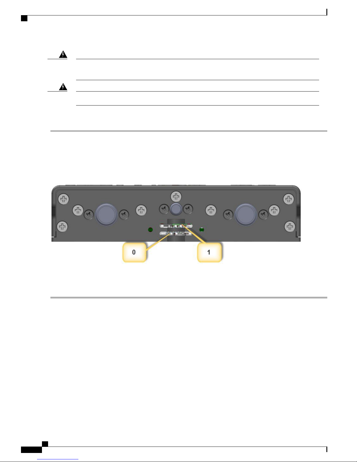
Locate the SIM card you wish to install/replace. The two slots are on the rear of the device. Slot 1 is the top and Slot 0
is the bottom. The following figure shows the slots with the protective cover removed.
The covers are an integral part of the safety design of the product. Do not operate the unit without the
covers installed. Statement 1077
Hot surface. Statement 1079Warning
To access the SIM card in the Cisco IR809, follow these steps:
Step 5
Step 6
If SIM card is present, then push the SIM card to eject it out of the slot. Install the new SIM card by pushing it into the
slot until you hear a clicking sound.
Replace the protective cover and the screws.
Modems
There is one mini-PCIe connector to support a 4G modem. The 4G modems from Sierra Wireless MC73xx
will be used:
Cisco 809 Industrial Integrated Services Router Hardware Installation Guide
4
Page 5

Installing the Router
Installing Antennas
4G (MIMO)3G (Diversity)2GCarrierModem ChipsetsProduct
MC7350
MC7354
MC7304
MDM9615
WTR1605L
PM8018
MDM9215
WTR1605L
PM8018
MDM9215
WTR1605L
PM8018
Verizon
Sprint
Canada
New Zealand
Australia
BC0 - CDMA
-800
BC1 - CDMA 1900
BC10 - CDMA
-800
Quad GSMATT
Quad GSMEurope
BC0 - CDMA
-800
BC1 - CDMA 1900
BC10 - CDMA
-800
B2 - UMTS
1900
B4 - UMTS
AWS
B5 - UMTS 850
B1 - UMTS
2100
B2 - UMTS
1900
B5 - UMTS 850
B6 - UMTS 800
B8 - UMTS 900
B4 - UMTS
AWS
B13 UMTS-700
B25 - PCS 1900
B2 - UMTS
1900
B4 - UMTS
AWS
B5 - UMTS 850
B7 UMTS-2600
B17 UMTS-700
B1 - UMTS
2100
B3 - UMTS
1800
B7 UMTS-2600
B8 - UMTS 900
B20 - UMTS E800
Installing Antennas
There are two TNC connectors on the backside of the device. The TNC connectors are used to connect to the
4G modem. The SMA connector is for the GPS antenna.
Orient the antennas. For optimum wireless performance, the antennas should be perpendicular with respect
to the floor.
If the router is being mounted on a desk, orient the antennas straight up.
To attach the radio antennas to your wireless router, follow these steps:
Before You Begin
Before you install the Cisco 809 Integrated Services Router on a table, wall, or DIN rail, install the antennas
on the back panel. It is difficult to install the antennas after the router is installed.
In some cases it is necessary to install two antennas:
Cisco 809 Industrial Integrated Services Router Hardware Installation Guide
5
Page 6

Mounting on a Wall, Table, or Other Flat Surface
Sierra Wireless MC73xx modem series supports MIMO on LTE. WCDMA UMTS HSPA DC-HSPA+
•
is diversity only, without MIMO.
The IR809 must be installed with 2 antennas (Main & Aux) to guarantee the best performance level.
•
Using a single antenna may impact downlink performance by a minimum of 3dB, and can be much more
(10-20dB) due to multipath fading (destructive interference between direct and reflected radio waves).
In case of 3G UMTS, a solo antenna would not be able to switch to the diversity port.
•
Installing the Router
Step 1
Step 2
Manually screw the antenna tight to the TNC connectors on the back of the router.
Orient the antennas. For optimum wireless performance, antennas should be generally perpendicular to each other.
Mounting on a Wall, Table, or Other Flat Surface
To mount the router on a wall, follow these steps:
Before You Begin
The Cisco 809 ISR has mounting holes on the bottom of the chassis for mounting the unit on a wall or other
vertical surface.
When choosing a location for wall-mounting the router, consider cable limitations and wall structure.Tip
Warning
Read the wall-mounting instructions carefully before beginning installation. Failure to use the correct
hardware or to follow the correct procedures could result in a hazardous situation to people and damage
to the system. Statement 378
Note
When mounted from the back using #10 screws, the torque is 22-30 in-lbs. When mounted from front
using #6 screws the torque is 8.3-11 in-lbs.
Step 1
6
Locate the mounting holes on the router. There are 4 holes shown by red arrows in the following figure:
Cisco 809 Industrial Integrated Services Router Hardware Installation Guide
Page 7

Installing the Router
Mounting on a Wall, Table, or Other Flat Surface
Step 2
Install the router to a wall stud using two number-10 wood screws, round- or pan-head, with number-10 washers or two
number-10 washer-head screws. The screws must be long enough to penetrate at least 1.0 inch (25.4 mm) into the
supporting wood or metal wall stud.
Note
For hollow-wall mounting, each bracket requires two wall anchors with washers. Wall anchors and washers
must be size number 10.
Cisco 809 Industrial Integrated Services Router Hardware Installation Guide
7
Page 8

Installing a DIN Rail
Installing the Router
Step 3
Route the cables so that they do not put a strain on the connectors or mounting hardware. To comply with IP 40, cables
should be routed down relative to the router to prevent water from traveling on the cables.
Installing a DIN Rail
The DIN Rail can be installed in two different orientations. With the cable side of the device facing up or
down. The DIN Rail bracket can be mounted on the front or the back of the router.
The IR809 meets IP30 rating when mounted vertically.Note
To attach the Cisco IR809 to a DIN rail, follow these steps:
Before You Begin
The DIN Rail kit is ordered separately.
Step 1
Attach the DIN rail bracket to the back of the router. Align the DIN rail bracket on the back of the router and secure/attach
it to the 4 mounting points using the screws provided. See the following figure.
Cisco 809 Industrial Integrated Services Router Hardware Installation Guide
8
Page 9

Installing the Router
Installing the Router Ground Connection
Step 2
Once the bracket is attached to the router, it can be mounted onto the DIN Rail. See the following figure.
Step 3
Step 4
Step 5
Step 6
Position the router so that the hook on the DIN rail bracket hooks onto the top edge of the DIN rail. The weight of the
product can rest on the hook temporarily while the DIN rail bracket latches are secured.
Pull down the spring loaded handles at the same time and slide the DIN Rail bracket up and over the latches.
Push the DIN rail bracket latch up after the router is over the DIN rail to secure it. The router is now installed in the DIN
rail.
To remove the router from the DIN Rail, simply reverse the procedure.
Installing the Router Ground Connection
To install the ground connection, follow these steps:
Before You Begin
The router must be connected to a reliable earth ground. Install the ground wire in accordance with local
electrical safety standards.
Cisco 809 Industrial Integrated Services Router Hardware Installation Guide
9
Page 10

Installing the Router Ground Connection
For NEC-compliant grounding, use size 14 AWG (1.6mm) or larger copper wire and a ring terminal
•
with an inner diameter of 1/4 in. (5 to 7 mm).
For EN/IEC 60950-compliant grounding, use size 18 AWG (1.02mm) or larger copper wire.
•
Installing the Router
Step 1
Step 2
Step 3
Warning
This equipment must be grounded. Never defeat the ground conductor or operate the equipment in the
absence of a suitably installed ground conductor. Contact the appropriate electrical inspection authority
or an electrician if you are uncertain that suitable grounding is available. Statement 1024
Warning
This equipment needs to be grounded. Use a green and yellow 14 to 18 AWG ground wire to connect the
host to earth ground during normal use. Statement 242
Locate the ring terminal lug and screw in the packaging kit. Store the ground screw for later use.
Use a wire stripping tool to strip the 14-16 AWG (1.6mm -to- 1.3mm) grounding wire to 0.22 in. (5.56 mm).
Insert the ground wire into the ring terminal lug, and using a crimping tool, crimp the terminal to the wire.
Step 4
Step 5
10
Slide the ground screw through the ground lug.
Insert the ground screw into the grounding point shown in the graphic.
Cisco 809 Industrial Integrated Services Router Hardware Installation Guide
Page 11

Installing the Router
Installing the Router Ground Connection
Step 6
Step 7
Use a ratcheting torque screwdriver to tighten the ground screw and ring terminal to the router side panel to 3.5 in-lb
(0.4 N-m). The torque should not exceed 3.5 in-lb (0.4 N-m).
Attach the other end of the ground wire(#1 in the graphic above) to a grounded bare metal surface, such as a ground bus,
a grounded DIN rail, or a grounded bare rack.
Cisco 809 Industrial Integrated Services Router Hardware Installation Guide
11
Page 12

Installing the Router Ground Connection
Installing the Router
Cisco 809 Industrial Integrated Services Router Hardware Installation Guide
12
 Loading...