

Page 1

Cisco IR800 Integrated Services Router Software Configuration Guide
First Published: 2016-12-20
Last Modified: 2020-03-25
Americas Headquarters
Cisco Systems, Inc.
170 West Tasman Drive
San Jose, CA 95134-1706
USA
http://www.cisco.com
Tel: 408 526-4000
800 553-NETS (6387)
Fax: 408 527-0883
Page 2

THE SPECIFICATIONS AND INFORMATION REGARDING THE PRODUCTS IN THIS MANUAL ARE SUBJECT TO CHANGE WITHOUT NOTICE. ALL STATEMENTS,
INFORMATION, AND RECOMMENDATIONS IN THIS MANUAL ARE BELIEVED TO BE ACCURATE BUT ARE PRESENTED WITHOUT WARRANTY OF ANY KIND,
EXPRESS OR IMPLIED. USERS MUST TAKE FULL RESPONSIBILITY FOR THEIR APPLICATION OF ANY PRODUCTS.
THE SOFTWARE LICENSE AND LIMITED WARRANTY FOR THE ACCOMPANYING PRODUCT ARE SET FORTH IN THE INFORMATION PACKET THAT SHIPPED WITH
THE PRODUCT AND ARE INCORPORATED HEREIN BY THIS REFERENCE. IF YOU ARE UNABLE TO LOCATE THE SOFTWARE LICENSE OR LIMITED WARRANTY,
CONTACT YOUR CISCO REPRESENTATIVE FOR A COPY.
The Cisco implementation of TCP header compression is an adaptation of a program developed by the University of California, Berkeley (UCB) as part of UCB's public domain version of
the UNIX operating system. All rights reserved. Copyright©1981, Regents of the University of California.
NOTWITHSTANDING ANY OTHER WARRANTY HEREIN, ALL DOCUMENT FILES AND SOFTWARE OF THESE SUPPLIERS ARE PROVIDED “AS IS" WITH ALL FAULTS.
CISCO AND THE ABOVE-NAMED SUPPLIERS DISCLAIM ALL WARRANTIES, EXPRESSED OR IMPLIED, INCLUDING, WITHOUT LIMITATION, THOSE OF
MERCHANTABILITY, FITNESS FOR A PARTICULAR PURPOSE AND NONINFRINGEMENT OR ARISING FROM A COURSE OF DEALING, USAGE, OR TRADE PRACTICE.
IN NO EVENT SHALL CISCO OR ITS SUPPLIERS BE LIABLE FOR ANY INDIRECT, SPECIAL, CONSEQUENTIAL, OR INCIDENTAL DAMAGES, INCLUDING, WITHOUT
LIMITATION, LOST PROFITS OR LOSS OR DAMAGE TO DATA ARISING OUT OF THE USE OR INABILITY TO USE THIS MANUAL, EVEN IF CISCO OR ITS SUPPLIERS
HAVE BEEN ADVISED OF THE POSSIBILITY OF SUCH DAMAGES.
Any Internet Protocol (IP) addresses and phone numbers used in this document are not intended to be actual addresses and phone numbers. Any examples, command display output, network
topology diagrams, and other figures included in the document are shown for illustrative purposes only. Any use of actual IP addresses or phone numbers in illustrative content is unintentional
and coincidental.
All printed copies and duplicate soft copies of this document are considered uncontrolled. See the current online version for the latest version.
Cisco has more than 200 offices worldwide. Addresses and phone numbers are listed on the Cisco website at www.cisco.com/go/offices.
Cisco and the Cisco logo are trademarks or registered trademarks of Cisco and/or its affiliates in the U.S. and other countries. To view a list of Cisco trademarks, go to this URL: www.cisco.com
go trademarks. Third-party trademarks mentioned are the property of their respective owners. The use of the word partner does not imply a partnership relationship between Cisco and any
other company. (1721R)
©
2016-2019–2020 Cisco Systems, Inc. All rights reserved.
Page 3

CONTENTS
Full Cisco Trademarks with Software License ?
Preface xi
Preface xi
CHAPTER 1
Product Overview 1
General Description 1
Hardware Overview 2
IR829 Product Overview 2
IR809 Product Overview 4
Reset Button 5
Booting a Default IOS Image and Default Configuration - Method 1 6
Booting a Default IOS Image and Default Configuration - Method 2 7
Configuration Register 7
Auto-recovery of Corrupt Filesystems 9
Plug and Play Agent (PnP) support over 4G/Ethernet 11
Plug and Play (PnP) Support on the IR829 LAN 12
Password Recovery 14
Software Overview 15
Hardware Differences Between IR809, IR829, and C819HG 16
Hardware Comparison 17
CHAPTER 2
Antenna Recommendations 18
Features Supported in Different IOS Releases 18
Related Documentation 22
Initial Configuration 23
Cisco IR800 Integrated Services Router Software Configuration Guide
iii
Page 4

Contents
IR800 Bootstrap Sequence and Troubleshooting 23
Sequence 1 24
Example from a tftp server: 24
Example from USB to IOS flash: 25
Sequence 2 26
Setup Command Facility 27
Verifying the Initial Configuration 30
LEDs 30
Single Modem 31
Dual Modem 31
Software Bundle Installation 34
Displaing Digital Signature and Software Authenticity 34
show software authenticity file command 34
CHAPTER 3
verify command 35
Bundle Installation Steps 36
Additional Software Bundle Installation Options 37
Power Over Ethernet (PoE) 38
LLDP (Link Layer Discovery Protocol) Support for 3rd party PoE devices 39
Serial Port Configuration 41
Configuring Accelerometer and Gyroscope 42
Auto-Negotiation Support for Gigabit-Ethernet 0 on the IR829 43
Where To Go From Here 43
Cellular Interface Modules 45
Cellular Interface 46
4G LTE Dual SIM 47
AutoSim and Firmware Based Switching 47
Dual Radio Configuration and Single Radio Configuration 48
Verizon Profile 52
AT&T Profile 53
Creating a Cellular Profile for Verizon. 53
Creating a Cellular Profile for AT&T 54
Other Useful Commands 56
Accessing 4G Modem AT Commands 57
Cisco IR800 Integrated Services Router Software Configuration Guide
iv
Page 5

Checking 4G Modem Firmware through AT Commands 58
Radio Frequency Band Select 59
Low Power Mode 60
Enhancement to Modem Crash Action 60
IR800 Cellular Technology Selection 61
GPS 64
GPS NMEA Multiple Stream 66
Setting up the Configuration 66
Troubleshooting the Cellular Interface 67
Contents
CHAPTER 4
CHAPTER 5
IR829 AP803 Access Point Module 71
Hardware Overview 71
Software Overview 72
IOS Internal Interfaces 72
IR829 IOS – AP803 Console Access 73
IR829 Service Module 74
AP803 Embedded Web Manager 75
Upgrading the Firmware on the AP803 76
Configuring Virtual-LPWA 77
Configuring Virtual-LPWA Interface on the IR800 Series 77
Configuring Ethernet Interface and Creating VLPWA Interface 78
Configuring IR809 for One Cisco LoRaWAN Gateway 78
Configuring IR809 for Multiple Cisco LoRaWAN Gateways 79
Configuring IR829 80
Configuring DHCP Pool for the Cisco LoRaWAN Gateway 80
Configuring SNMP TRAP for Modem Notifications 82
Configuring VLPWA Interface and Associated Cisco LoRaWAN Gateway 83
Configuring IR809 for One Cisco LoRaWAN Gateway 84
Configuring Cisco LoRaWAN Gateway Password 85
Configuring Console Access 85
Configuring Clock for the Cisco LoRaWAN Gateway 86
Configuring NTP Server for the Cisco LoRaWAN Gateway 86
Configuring GPS as the Clock Source 87
Cisco IR800 Integrated Services Router Software Configuration Guide
v
Page 6

Contents
Configuring Cisco LoRaWAN Gateway Timezone 87
Configuring IPSec on the Cisco LoRaWAN Gateway 88
Configuring SCEP on the Cisco LoRaWAN Gateway 88
Configuring Security Protection 90
Managing the Cisco LoRaWAN Gateway 91
LoRaWAN Modem Firmware Upgrade 92
Installing U-boot 94
LoRaWAN Gateway FPGA Upgrade 94
Uploading a File to the LoRaWAN Gateway 95
Monitoring the LoRaWAN Gateway 95
Monitoring LED Status 99
Checking Connectivity 99
Debugging the LoRaWAN Gateway 99
CHAPTER 6
CHAPTER 7
Alarms 101
Finding Feature Information 101
Information About Alarms 101
Alarm Port 101
Alarm Conditions 102
Configuration Commands 102
Configuration Examples 103
Enabling SNMP Traps 104
MIBs 104
Guest Operating System (Guest OS) Installation and Configuration 105
Guest Operating System Overview 105
Prerequisites 106
Guidelines and Limitations 106
Default Settings 107
Installation and Upgrade 108
Improvements in IOS and Guest-OS Clock Time Synchronization 108
Configuring Cisco IOS 109
Configuring the IR800 Ethernet Interface 109
IPv6 Gigabit Ethernet 109
Cisco IR800 Integrated Services Router Software Configuration Guide
vi
Page 7

Enabling IPv4 Gigabit Ethernet 110
Configuring DHCP Pool 110
Configuring Guest OS GigabitEthernet on Cisco IOS 111
Configuring Guest OS 111
Starting Guest OS 111
Guest OS persistent logging through reload 112
Guest OS file system corruption detection and recovery 112
IOx Radius authentication 113
IOXVM Storage Partition Enhancement 113
Configuring Network Address Translation (NAT) 114
IR800 Guest-OS USB Access from IOS 115
New for IOS 15.6(1)T 115
New for IOS 15.6(3)M 116
Contents
CHAPTER 8
USB Support 116
Serial Device Configuration 116
Serial Relay Configuration 116
Memory Allocation Optimization 117
New for IOS 15.7(3)M 117
Troubleshooting 118
Checking Connectivity 119
Related Documentation 119
WAN Monitoring 121
Information About WANMon 121
Built-in Recovery Actions 121
Prerequisites 122
Guidelines and Limitations 122
Configuring WANMon 123
Verifying WANMon Configuration 124
Configuration Examples 125
WANMon Cellular Interface Configuration Example 125
Multiple WAN Link Monitoring Example 125
Related Documentation 126
Cisco IR800 Integrated Services Router Software Configuration Guide
vii
Page 8

Contents
CHAPTER 9
CHAPTER 10
CHAPTER 11
Ignition Power Management 127
Features of Ignition Power Management 127
Command Line Interface (CLI) 128
Configuration CLI 128
Status CLI 128
Troubleshooting CLI 129
Command Examples 131
Default Values 132
Licensing and Security 133
Licensing 133
Licensing CLI 134
Hardware Crypto Support 134
mSATA SSD as Additional Storage 137
mSATA Overview 137
CHAPTER 12
CHAPTER 13
IR829M SKUs 137
Using the mSATA SSD 138
Displaying the Wear Leveling Data for the mSATA SSD 139
IR829M: MIB support for mSATA Wear Ratio and Usage 139
Example: Actual OID and output of SNMP get/walk on OID 140
Feature Details 140
Feature Assumptions 140
IR829M OIDs 141
Client Information Signaling Protocol (CISP) 143
Client Information Signaling Protocol (CISP) 143
CISP Commands 143
CISP Prerequisites 144
Flow Diagrams 144
Dot1x Supplicant Support on the L2 interface 147
viii
Cisco IR800 Integrated Services Router Software Configuration Guide
Page 9

Dot1x Supplicant Support on the L2 interface 147
Sample Configuration to Support DOT1x Supplicant on the IR829 148
Contents
CHAPTER 14
Network Management Solutions 151
Cisco IoT Field Network Director (formerly referred to as CG-NMS) 151
IR809 and IR829: PNP Image Upgrade from FND 153
Image Installation 153
Feature Assumptions 154
Cisco Configuration Professional Express 155
Cisco Kinetic 155
Cisco Prime Infrastructure 156
Davra RuBAN 156
Cisco IoT Fog Director 156
About Cisco IOx 156
About Cisco Fog Director 156
OID and Inventory 157
Cisco IR800 Integrated Services Router Software Configuration Guide
ix
Page 10

Contents
Cisco IR800 Integrated Services Router Software Configuration Guide
x
Page 11

Preface
Preface
This preface describes the objectives, audience, organization, and conventions of this guide and describes
related documents that have additional information.
This preface describes the objectives, audience, organization, and conventions of this guide and describes
related documents that have additional information. It contains the following sections:
Objective
This guide provides an overview of the software features and explains how to perform the configuration steps
for the Cisco IR800 Integrated Services Routers.
Audience
This guide is intended for people who have a high level of technical ability, although they may not have
experience with Cisco software.
Conventions
This section describes the conventions used in this guide.
Note
Caution
Tip
Means reader take note. Notes contain helpful suggestions or references to additional information and material.
This symbol means reader be careful. In this situation, you might do something that could result in equipment
damage or loss of data.
Means the following information will help you solve a problem . The tip information might not be
troubleshooting or even an action, but could be useful information.
Searching Cisco Documents
To search an HTML document using a web browser, press Ctrl-F (Windows) or Cmd-F (Apple). In most
browsers, the option to search whole words only, invoke case sensitivity, or search forward and backward is
also available.
To search a PDF document in Adobe Reader, use the basic Find toolbar (Ctrl-F) or the Full Reader Search
window (Shift-Ctrl-F). Use the Find toolbar to find words or phrases within a specific document. Use the
Full Reader Search window to search multiple PDF files simultaneously and to change case sensitivity and
other options. Adobe Reader’s online help has more information about how to search PDF documents.
Cisco IR800 Integrated Services Router Software Configuration Guide
xi
Page 12

Preface
Preface
xii
Cisco IR800 Integrated Services Router Software Configuration Guide
Page 13

Product Overview
This chapter provides an overview of the features available for the Cisco IR800 Integrated Services Routers
(ISRs).
• General Description, on page 1
• Hardware Overview, on page 2
• Software Overview, on page 15
• Hardware Differences Between IR809, IR829, and C819HG, on page 16
• Antenna Recommendations, on page 18
• Features Supported in Different IOS Releases, on page 18
• Related Documentation, on page 22
General Description
The 800 Series Industrial Integrated Services Routers are compact, ruggedized, Cisco IOS Software routers.
They offer support for integrated 4G LTE wireless WAN (both 809 and 829 models) and wireless LAN
capabilities (829 model only). The IR829 offers an Internal WLAN Access Point which runs on-board the
router. The AP803 runs its own IOS software independently from the IR829 IOS, and requires configuring.
The AP803 works as a standalone access point or with a wireless controller.
CHAPTER 1
They offer:
• Easily and rapidly deployable
• Highly available, highly secure, and reliable
• Designed for machine-to-machine (M2M) communication and for mobile vehicle communication in
harsh environmental conditions
• Designed to withstand hostile environments, tolerating a wide temperature range
These industrialized routers deliver enterprise-class features, including highly secure data, voice, and video
communications to stationary and mobile network nodes across wired and wireless links. They can deliver
enterprise-grade, wireline-like functionality.
The routers also support Cisco IOx Software, providing an open, extensible environment for hosting additional
operating systems and applications directly at the network edge. They can enhance other Cisco IoT System
products across multiple industries, including transportation, manufacturing, electrical utilities, and others.
Cisco IR800 Integrated Services Router Software Configuration Guide
1
Page 14

Hardware Overview
For a complete listing of the routers capabilities, see the Cisco 829 Industrial Integrated Services Routers
Product Information .
Hardware Overview
This section covers the overview of the IR809 and IR829.
IR829 Product Overview
Figure 1: Cisco IR829 Integrated Services Router, on page 2 shows the IR829.
Figure 1: Cisco IR829 Integrated Services Router
Figure 2: Cisco IR829 Front Panel Single Modem, on page 2 shows the front panel details of the Cisco
IR829 Single Modem.
Figure 2: Cisco IR829 Front Panel Single Modem
Product Overview
Serial Ports5CELLULAR 0 AUX1
USB-A Port6mSATA Slot2
Power Input, Battery, and Ignition connector. Refer to the DC Power
7Gigabit WAN (SFP)3
section for pin-outs.
WLAN ANT 0 2.4GHz8Gigabit Ethernet LAN/PoE (RJ45)4
Figure 3: Cisco IR829 Front Panel Duel Modem, on page 2 shows the front panel details of the Cisco IR829
Dual Modem.
Figure 3: Cisco IR829 Front Panel Duel Modem
Serial Ports5CELLULAR 0 AUX1
USB-A Port6mSATA Slot2
Power Input, Battery, and Ignition connector. Refer to the DC Power
7Gigabit WAN (SFP)3
section for pin-outs.
WLAN ANT 0 2.4/5GHz8Gigabit Ethernet LAN/PoE (RJ45)4
Figure 4: Cisco IR829 Back Panel Single Modem, on page 3 shows the back panels details of the Cisco
IR829 Single Modem.
Cisco IR800 Integrated Services Router Software Configuration Guide
2
Page 15
Product Overview
Figure 4: Cisco IR829 Back Panel Single Modem
IR829 Product Overview
Denotes SIM card order, SIM0 on top and
5WLAN ANT 0 5GHz1
SIM1 on bottom.
WLAN ANT 1 5GHz6WLAN ANT 1 2.4GHz2
3
CELLULAR 0 MAIN7Cover over SIM cards, reset button and console port cover,
see Figure 6: Behind the SIM Door, on page 3
GPS SMA4
Figure 5: Cisco IR829 Back Panel Dual Modem, on page 3 shows the back panels details of the Cisco IR829
Dual Modem.
Figure 5: Cisco IR829 Back Panel Dual Modem
Denotes SIM card order, SIM0 on top and
5Cellular 1 Main1
SIM1 on bottom.
Cellular 1 AUX6WLAN ANT 1 2.4/5GHz2
3
CELLULAR 0 MAIN7Cover over SIM cards, reset button and console port cover,
see Figure 6: Behind the SIM Door, on page 3
GPS SMA4
Note
Behind the SIM Door Assembly, there is a reset switch (1), Mini USB console port (2), and Dual SIM slots
(3). See Figure 6: Behind the SIM Door, on page 3 for details
Figure 6: Behind the SIM Door
Figure 7: Cisco IR829 Top Cover, on page 3 shows the top of the Cisco IR829.
Figure 7: Cisco IR829 Top Cover
Figure 8: Cisco IR829 LED Detail, on page 3 shows the LED detail from the Dual Modem SKU. Single
Modem SKUs will only have Cellular0 LEDs.
Figure 8: Cisco IR829 LED Detail
Cisco IR800 Integrated Services Router Software Configuration Guide
3
Page 16
IR809 Product Overview
IR809 Product Overview
The following figure shows the IR809.
Figure 9: Cisco IR809 Integrated Services Router
The following figure shows the front panel details of the Cisco IR809.
Figure 10: Cisco IR809 Front Panel
Product Overview
Grounding Point8S0 RS232 DCE/RS485 Combo Port1
Mini type-B USB console/debug port9S1 RS232 DTE only2
SYS LED10GE0 (10/100/1000)3
Alarm LED11GE1 (10/100/1000)4
WAN/WWAN LEDs12USB 2.0 (Type-A Host Port)5
SIM Card LEDs13RESET Button6
DC Power/Alarm Connector7
Note
LEDs are viewable from the top and from the front of the IR809.
The following figure shows the back panels details of the Cisco IR809.
Figure 11: Cisco IR809 Back Panel
DIV TNC connector for 4G Modem1
SMA connector for GPS2
SIM0 and SIM1 Card Slots3
MAIN TNC connector for 4G Modem4
The following figure shows the top cover details of the Cisco IR809.
Figure 12: Cisco IR809 Top Cover
Cisco IR800 Integrated Services Router Software Configuration Guide
4
Page 17

Product Overview
Note
Reset Button
Note
Reset Button
See the respective Hardware Installation Guides for detailed description of the LEDs.
The reset button resets the router configuration to the default configuration set by the factory. To restore the
router configuration to the default configuration set by the factory, use a standard size #1 paper clip with wire
gauge 0.033 inch or smaller and simultaneously press the reset button while applying power to the router.
On the IR829, the rear cover must be removed to expose the reset switch.
Starting with release 15.6(1)T, the IR809 and IR829 have changed the way the reset button works. The IR800
series platforms now perform in the same manner as the C819. The high level description of the functionality
works like this:
• Press and hold the reset button while powering up the router
• During warm reboot this button has no impact on performance
• Simply pressing the button at any time does not reset the router
• The router will not react to the reset button if it is pressed after power-up because the button needs to be
pushed before turning ON/inserting power – to make sure that the condition is detected.
• The push-button cannot be used to boot a IOS image from network. The golden image has to be on flash:
only
Note
For the location of the reset button, see the appropriate IR809 or IR829 Hardware Installation Guide.
Perform the following steps to use the reset button:
Procedure
Step 1 Unplug power.
Step 2 Press the reset button on the router.
Step 3 Power up the system while holding down the reset button.
Step 4 Check the “boot system” setting configuration in the default configuration file (prior to saving it to
startup-config), and verify that it points to an existing IOS image on the flash: partition. Note: If that particular
IOS image is not present, the device will drop in rommon-2 mode and you will need to manually boot an IOS
image from there.
Step 5 Copy your desired default config file to the startup-config.
Step 6 Reload the router. Do NOT enter Yes if prompted whether you want to save the running-config to startup-config.
Cisco IR800 Integrated Services Router Software Configuration Guide
5
Page 18

Booting a Default IOS Image and Default Configuration - Method 1
Example
An example of the log activity after a reboot follows:
IR800# show log
*Nov 30 19:31:04.925: %LINEPROTO-5-UPDOWN: Line protocol on Interface GigabitEthernet0,
changed state to down
*Nov 30 19:31:10.651: %PLATFORM-5-RESET_BUTTON: Reset Button pressed during boot up.
*Nov 30 19:31:11.527: %LINK-3-UPDOWN: Interface Async0, changed state to up
*Nov 30 19:31:11.595: %SYS-5-RESTART: System restarted --
Cisco IOS Software, ir800 Software (ir800-UNIVERSALK9-M), Version 15.6(1)T, RELEASE
SOFTWARE (fc1)
What to do next
Product Overview
Note
To simplify the boot process, the IR800 routers do not support the ROMMON configuration register and the
associated CLI commands. The IR800 either boots the pre-configured images, or stops at the ROMMON
prompt for user intervention. In the event of a boot failure, see Chapter 3, “Setup Command Facility” for
additional information.
Booting a Default IOS Image and Default Configuration - Method 1
The IR800 differs from traditional IOS routers when booting a default IOS image and a default configuration.
These steps apply on a device running 15.6(1)T or later.
Method 1:
Procedure
Step 1 Save a copy of your IR800 IOS image with the .default extension on flash. For example: ios-image.default.
Step 2 Save a copy of your IR800 Hypervisor image with the .default extension on bootstrap. For example:
hypervisor-image.default.
Step 3 Save your desired default configuration file with the .cfg extension on flash. For example: config.cfg.
Step 4 Reset your IR800 router by powering it down, then press and hold the RESET button while powering up the
device.
The IR800 router will automatically boot hypervisor-image.default, then ios-image.default, and load the
config.cfg.
Step 5 Make sure there exists only one IOS image with a .default extension, only one configuration file with the .cfg
extension on the flash, and only one hypervisor image with the .default extension on bootstrap.
Cisco IR800 Integrated Services Router Software Configuration Guide
6
Page 19

Product Overview
Booting a Default IOS Image and Default Configuration - Method 2
Booting a Default IOS Image and Default Configuration - Method 2
If you do not have a config.cfg on flash, it will boot with the Cisco default configuration (aka: empty)
startup-config.
Method 2:
Procedure
Step 1 Check the “boot system” setting configuration in the default configuration file (prior to saving it to
startup-config), and verify that it points to an existing IOS image on the flash: partition.
Note
Step 2 Copy your desired default config file to the startup-config.
Step 3 Reload the router. Do NOT enter Yes if prompted whether you want to save the running-config to startup-config.
What to do next
An example of the log activity after a reboot follows:
IR800# show log
*Nov 30 19:31:04.925: %LINEPROTO-5-UPDOWN: Line protocol on Interface GigabitEthernet0,
changed state to down
*Nov 30 19:31:10.651: %PLATFORM-5-RESET_BUTTON: Reset Button pressed during boot up.
*Nov 30 19:31:11.527: %LINK-3-UPDOWN: Interface Async0, changed state to up
*Nov 30 19:31:11.595: %SYS-5-RESTART: System restarted -Cisco IOS Software, ir800 Software (ir800-UNIVERSALK9-M), Version 15.6(1)T, RELEASE SOFTWARE
(fc1)
Configuration Register
To configure the register:
IR800#conf t
Enter configuration commands, one per line. End with CNTL/Z.
IR800(config)#config-register 0x?
<0x0-0xFFFF>
IR800(config)#config-register 0x102
IR800(config)#
Jul 26 22:10:22.790: Bootstrap Emulator called with code 62
Jul 26 22:10:22.790: Bootstrap Emulator called with code 61
IR800(config)#
If that particular IOS image is not present, the device will drop in rommon-2 mode and you will
need to manually boot an IOS image from there.
To display the register:
IR800#sh ver
…..
…..
…..
Configuration register is 0x2101 (will be 0x102 at next reload)
The Format for the configuration registers is 0 x _ _ _ _ (4 bytes)
For example:
Cisco IR800 Integrated Services Router Software Configuration Guide
7
Page 20

Configuration Register
Product Overview
0x102, 0x2102, 0x2142, 0x142, 0x101, 0x2101
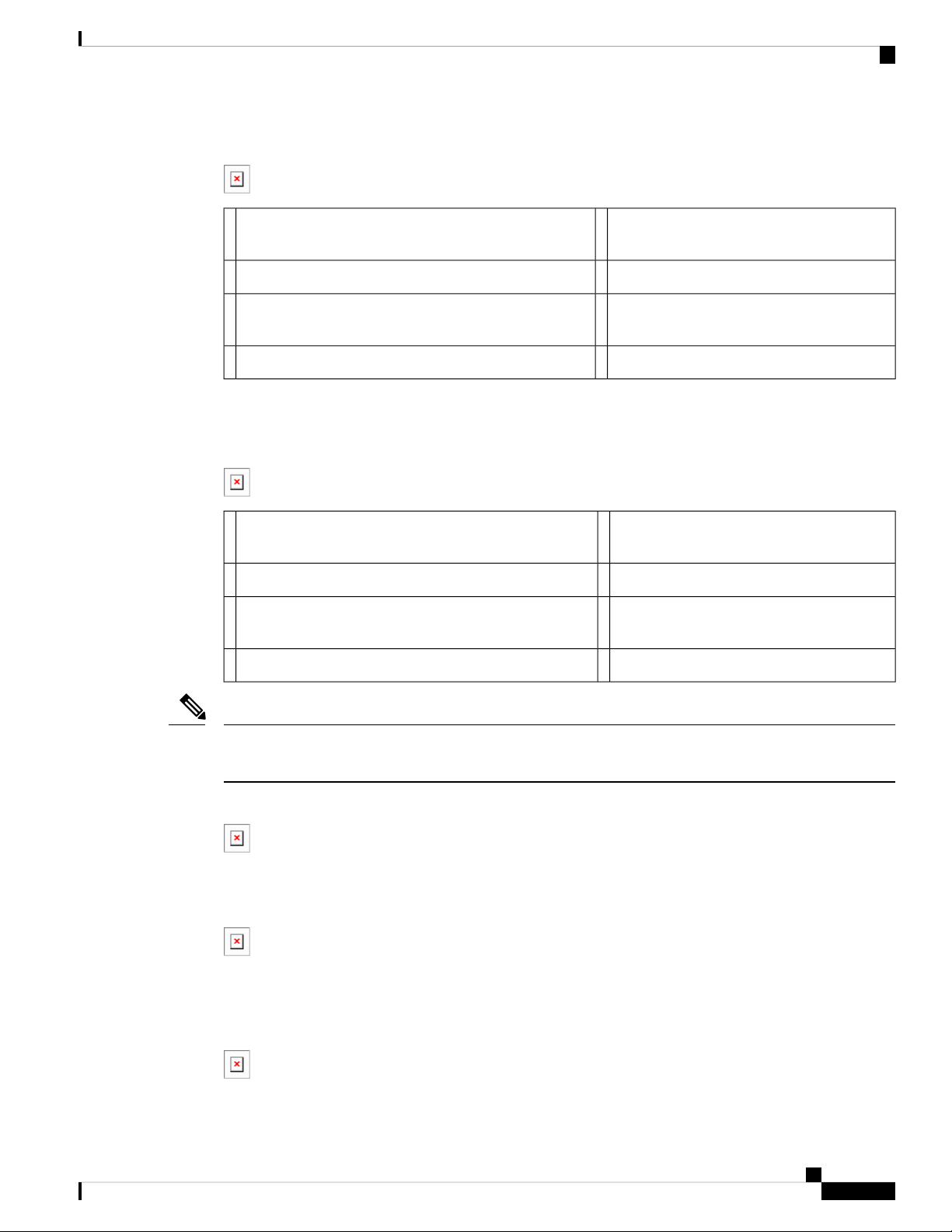
The Configuration Register 1st byte table shows the configuration register 1st byte values and descriptions.
Table 1: Configuration Register 1st byte
DescriptionValue
0
Boots into rommon 2 on reload.
Importance – access to rommon mode and rommon parameters can be
changed.
1
Ignores auto-boot and boots first image in flash.
In case of failure to boot the first image, it will try a maximum of 3 times to
boot the same image and then halt in rommon 2.
Importance – Irrespective of auto-boot string it will boot first image from
flash.
Auto-boot is ignored.
2 to F
Checks auto-boot and if present, the device will boot with auto-boot string.
If auto-boot is not present, then the device will boot first image from flash.
In case of failure to boot the first image, it will try a maximum of 3 times to
boot the same image and then halt in rommon 2.
Importance - Auto-boot has the higher priority, and if that fails then the
device will boot-up with first image.
The Configuration Register 2nd byte table shows the configuration register 2nd byte values and descriptions.
Table 2: Configuration Register 2nd byte
DescriptionValue
0
On reload after the device boots up with an image, it will have all the
configuration stored in startup config.
4
On reload after the device boots up with an image, it will ignore the startup
config and stays on config dialog box for user to enter configuration.
Note
startup-config is still present however not used by router
Importance – Used for password recovery.
The Configuration Register 3rd byte table shows the configuration register 3rd byte values and descriptions.
Table 3: Configuration Register 3rd byte
DescriptionValue
0 or 1
Allows the user to break and get into rommon mode by pressing Ctrl C.
Importance – To debug or to set something in rommon mode.
Cisco IR800 Integrated Services Router Software Configuration Guide
8
Page 21

Product Overview
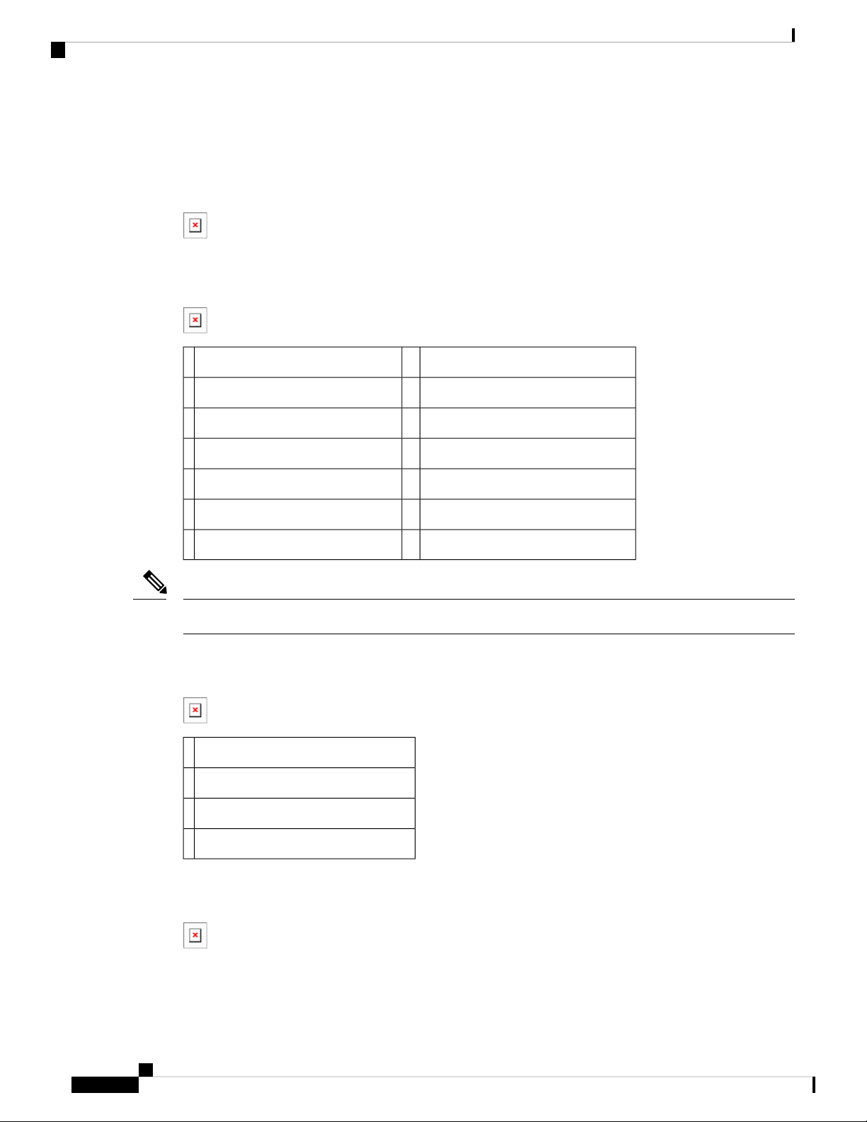
The Configuration Register 4th byte table shows the configuration register 4th byte values and descriptions.
Table 4: Configuration Register4th byte
Auto-recovery of Corrupt Filesystems
On rare occasions, the router could get stuck in ROMMON to flash and bootstrap file system corruption
caused by hard reloads. Hard reloads can be a consequence of fluctuating voltage or very low current. The
file system (in flash: or bootstrap:) is completely inaccessible at this point.
Starting with 15.8(3)M, on the IR8x9 platforms, software will automatically recover the router if one or more
filesystems are corrupt. This feature is enabled once the user executes bundle install, write memory, reload.
For example:
IR800#bundle install flash:ir800-universalk9-bundle.SSA.158-3.0m.M
Installing bundle image: /ir800-universalk9-bundle.SSA.158-3.0m.M......
...........................
updating Hypervisor image...
Sending file modes: C0444 25196401 ir800-hv.srp.SPA.3.0.55
SRP md5 verification passed!
updating IOS image...
Sending file modes: C0644 64486377 ir800-universalk9-mz.SSA.158-3.0m.M
IOS md5 verification passed!
Done!
Performing image backup .........Done!
Auto-recovery of Corrupt Filesystems
DescriptionValue
Doesn’t make any difference, behavior is decided by next 3 bytes.0 or 2
During the bundle installation, the user will observe the message "Backup partition successful'. Once the
bundle install is complete, the user can also verify if backup is successful using show platform bundle.
For example:
IR800#show platform bundle
Installed
Backup Success
This backup partition is taken from the Guest-OS data partition on the IR809, IR829, IR829GW, IR829B
products.
The IR829M products mSATA SSD partition is unaffected.
If a previous user was already using up this extra partition in old software, the new software will NOT proceed
with creating a backup partition. This ensures the user data is always intact. If the user wants to trigger a
backup, ~300Mb needs to be cleaned up from Guest-OS /dev/sdb. In some routers, Guest-OS /dev/sdb may
appear to have ~250Mb lesser, and some ~330Mb. This is due to the two different versions of eMMC on the
IR8x9s, and there is no software cli to provide eMMC part number to distinguish.
Files Backed Up to the New Backup Partition
• IOS image
• Hypervisor image
• Guest-OS image (if IOX Recovery is enabled using conf t then iox recovery-enable)
Cisco IR800 Integrated Services Router Software Configuration Guide
9
Page 22

Auto-recovery of Corrupt Filesystems
• Standard Files:
• Entire eem folder
• The entire managed folder, except managed/images
• All pnp* files (all PnP related files)
• vlan.dat
• Archive folder
• Field Network Director specific files:
• express-setup-config
• before-registration-config
• before-tunnel-config
• Sample file labeled additional_backup_file (This file is to ensure if a user wants to customize low sized
(50 kbytes or less) configuration file copy, they can save it in this name and it will be backed up.
Product Overview
Files NOT Backed Up to the New Backup Partition
• Duplicates of software images in managed/images
• User generated files, folders and configurations
• FW of 4G modems
• IOx application data
Notes:
The backup partition is limited in space and only for basic device recovery, and to load startup -config [as
SPI Flash: is intact]. In this manner, remote device reachability is back up again. Remaining files need to be
restored again by end user.
If a user running old software would like to increase their current Guest-OS disk space, it is recommended to
take a data backup, and execute the following command taking up larger disk space. Starting at IOS release
156(3)M3 and greater, the default disk space allocated to Guest-OS is Option 1 from the example below. For
previous releases default used to be Option 6 from the example below.
IR800#guest-os 1 disk-repartition ?
1 disk1: 500MB vs disk2: 1800MB
2 disk1: 700MB vs disk2: 1600MB
3 disk1: 900MB vs disk2: 1400MB
4 disk1: 1100MB vs disk2: 1200MB
5 disk1: 1300MB vs disk2: 1000MB
6 disk1: 1500MB vs disk2: 800MB
7 disk1: 1700MB vs disk2: 600MB
Note: Actual storage available for applications will be less than the value chosen for all profiles. The disk2
partition displayed in the15.8(3)M release has to account for 300MB less space. For example: option1, disk2
is 1500MB not 1800MB. In future releases, this will be corrected.
Cisco IR800 Integrated Services Router Software Configuration Guide
10
Page 23

Product Overview
Once an auto-recovery is complete, the user will observe a small file in flash called fs_recovered.ios. It will
contain the timestamp of the last recovery. This file is indication that backup was successful, and that there
was indeed a corruption of the filesystem. This file is not persistent on soft reload of the router.
Alternatively, the user can also backup using:
IR800#hypervisor backup_images
WARNING - If you are running this command for the first time, it might delete all application
data in IOx. This operation cannot be undone. Continue? [yes/no]: y
Performing image backup......... Done
This will ensure the latest sync of vlan.dat, pnp and managed configs.
The first time the command is executed, it will forcibly create the backup. If an IOx user was using up the
300Mb required for backup partition creation from an older IOS release, then it will be carved into backup
and the user will loose data. The user can opt for 'no' and perform a manual backup of that data before
proceeding with hypervisor backup_images command.
Plug and Play Agent (PnP) support over 4G/Ethernet
Plug and Play Agent (PnP) support over 4G/Ethernet
An option was added to the bundle install command:
bundle install <bundle_image_name> rom-autoboot
When this option is specified, the IOS system image to boot will NOT be written into the running-config.
Instead, it will be set into the rommon BOOT variable (BOOT=<system_image>) ONLY.
After bundle install <bundle_image_name> rom-autoboot and write erase commands, when the device reloads
it will automatically boot up the IOS image saved in rommon BOOT. This also ensures the device does not
have any startup configuration when it boots up so it will allow PNP to start up.
PNP can be started either using Ethernet or cellular 4G. If connected to both, Ethernet will take precedence
over Cellular 4G.
PNP using Ethernet can be done in three different ways:
1. Specifying OPTION 43 on DHCP ROUTER
Example: option 43 ascii 5A1D;B2;K4;I<APIC-EM_IP_ADDRESS>;J80
2. Specifying DNS on DHCP ROUTER
Example: domain-name test.com
#conf t
#ip host pnpserver.test.com <APIC-EM address>
3. Specifying CCO’s address by configuring devicehelper.cisco.com on DHCP ROUTER
#conf t
#ip host devicehelper.cisco.com <CCO_address>
PNP using 4G cellular can be done by configuring the device information (Serial number, PID and controller
profile-APIC-EM) on CCO.
Once PNP is completed, issue a write mem command to save the configuration. PNP pushes the configuration
but does not save it. The configuration must be saved after PNP is successfully completed.
To verify if PNP is completed or not, verify with the sh run command. At the bottom of the command output,
there should be a pnp profile and the APIC EM address. This means the device was redirected to APIC-EM
Cisco IR800 Integrated Services Router Software Configuration Guide
11
Page 24

Plug and Play (PnP) Support on the IR829 LAN
and the initial PNP was successfully done. Now once the configuration file is pushed from APIC-EM, verify
this using the sh pnp task command and verify the Config-Upgrade Task should have Result: Success.
Note
The device should not be interrupted until PNP is completed. If the device is interrupted, PNP will stop. If at
any point something goes wrong, reload the router without saving the configuration and PNP will start once
again. Once PNP is completed it is necessary to save the configuration by issuing the write mem command.
IR800#sh run | b pnp
pnp profile pnp-zero-touch
transport https ipv4 172.27.122.132 port 443
end
IR800#sh pnp task
------------------ show pnp tasks --------------------Certificate-Install Task - Last Run ID:5, ST:7201, Result:Success,
LT:117562, ET:4 ms
Src:[-], Dst:[-]
Device-Auth Task - Never Run
Device-Info Task - Last Run ID:9, ST:5301, Result:Success, LT:200634, ET:1 ms Src:[udi],
Dst:[pnp-zero-touch]
Image-Install Task - Never Run
SMU Task - Never Run
Config-Upgrade Task - Last Run ID:10, ST:5202, Result:Success, LT:267420, ET:984 ms
Src:[https://192.168.1.1:443/api/v1/file/onetimedownload/1530b4e5-beb8-4db3-b4df-28dc016464fc],
Dst:[running]
CLI-Config Task - Never Run
Licensing Task - Never Run
File-Transfer Task - Never Run
Redirection Task - Never Run
CLI-Exec Task - Last Run ID:12, ST:5401, Result:Success, LT:279464, ET:1 ms
Src:[cli-exec request], Dst:[running-exec]
Script Task - Never Run
Product Overview
Additional Resources for Cisco Plug and Play can be found at the following links:
Plug and Play (PnP) Support on the IR829 LAN
Feature applies to the IR829 product series only
Starting with this release, PnP will be supported over LAN ports (G1 to G4). In previous releases, PnP was
supported only over WAN port and 4G LTE.
Similar to WAN port, PnP over LAN Interfaces can be triggered by configuring either DHCP, DNS or CCO
details on DHCP/DNS server. Since all the LAN interfaces default to Vlan1, when the router boots up in
factory default mode, it acquires an IP address from either DHCP or DNS server through Vlan1. This is how
PnP is initiated. Once the initial PnP discovery is successful and the router is discovered on the PnP Server
(for example: any Network Management System such as Field Network Director, APIC-EM, DNAC to name
a few), it will be in an unclaimed state. From here, the user can 'claim' the device and push required
configurations from the PnP server to the router.
Note: Image upgrade from the PnP server is currently not supported.
PnP using Ethernet can be done in three different ways:
1. Specifying OPTION 43 on DHCP router
ip dhcp pool IOT_address
Cisco IR800 Integrated Services Router Software Configuration Guide
12
Page 25

Product Overview
Plug and Play (PnP) Support on the IR829 LAN
network 192.168.1.0 255.255.255.0
default-router 192.168.1.1
option 43 ascii 5A1D;B2;K4;I172.23.165.116;J80
ntp master
2. Specifying DNS on DHCP router
ip dhcp pool IOT_DNS
network 192.168.2.0 255.255.255.0
default-router 192.168.2.1
domain-name pnp-agent-tb.cisco.com
dns-server 192.168.2.1
ip host pnpserver.pnp-agent-tb.cisco.com 172.23.165.116
ip host pnpntpserver.pnp-agent-tb.cisco.com 172.23.165.116
ip dns server
3. Specifying CCO’s address by configuring devicehelper.cisco.com on DHCP router
ip dhcp pool IOT_dhcp
network 192.168.3.0 255.255.255.0
default-router 192.168.3.1
dns-server 192.168.3.1
ip host devicehelper.cisco.com 64.101.32.10
ip host time-pnp.cisco.com 192.168.3.1
ntp master
Note: Once PnP is completed, issue a write mem command to save the configuration. PnP pushes the
configuration but does not save it. The configuration must be saved after PnP is successfully completed.
To verify if PnP is completed or not, verify with the show run command. At the bottom of the command
output, there should be a PnP profile and the PnP controller IP address. This means the device was redirected
to the PnP server and the PnP discovery was successfully done. Once the configuration file is pushed from
the PnP server, verify this using the show pnp task command and verify the Config-Upgrade Task should
show Result: Success.
You can further debug and verify the entire PnP process using the commands show pnp summary, show
pnp trace and show pnp tech-support.
Note: The device should not be interrupted until PnP is completed. If the device is interrupted, PnP will stop.
If at any point something goes wrong, reload the router without saving the configuration and PnP will start
once again. Once PnP is completed it is necessary to save the configuration by issuing the write memcommand.
IR800#show running-config | begin pnp profile
pnp profile pnp_redirection_profile
transport https ipv4 128.107.248.237 port 443
!
end
IR800#show pnp task
------------------ show pnp tasks --------------------Certificate-Install Task - Last Run ID:5, ST:7201, Result:Success,
LT:117562, ET:4 ms
Src:[-], Dst:[-]
Device-Auth Task - Never Run
Device-Info Task - Last Run ID:9, ST:5301, Result:Success, LT:200634, ET:1 ms Src:[udi],
Dst:[pnp-zero-touch]
Image-Install Task - Never Run
SMU Task - Never Run
Config-Upgrade Task - Last Run ID:10, ST:5202, Result:Success, LT:267420, ET:984 ms
Src:[https://192.168.1.1:443/api/v1/file/onetimedownload/1530b4e5-beb8-4db3-b4df-28dc016464fc],
Dst:[running]
CLI-Config Task - Never Run
Cisco IR800 Integrated Services Router Software Configuration Guide
13
Page 26

Password Recovery
Licensing Task - Never Run
File-Transfer Task - Never Run
Redirection Task - Never Run
CLI-Exec Task - Last Run ID:12, ST:5401, Result:Success, LT:279464, ET:1 ms
Src:[cli-exec request], Dst:[running-exec]
Script Task - Never Run
Password Recovery
Use the following procedure in the event you have lost the router password.
Procedure
Step 1 Copy a ".cfg" configuration file in the router flash memory without any "username", "password", or "AAA"
statements.
Example:
IR800# copy usb:default-config flash:default-config.cfg
Destination filename [default-config.cfg]?
Product Overview
In the router flash memory you must have only one ".cfg" at a time. If there are two or more the system will
be confused resulting in unexpected behavior.
Step 2 Make a copy of the "startup-config" file in the router flash memory without an extension.
Example:
IR800# copy startup-config flash:startup-config
Destination filename [startup-config.cfg]?
Step 3 Power-off the router. Press the "Reset Button" and power-on the router, holding the button for 30sec. The
router should boot with the new ".cfg" file.
Step 4 Copy the "startup-config" file over the "running-config".
Example:
IR800# copy flash:startup-config running-config
Destination filename [startup-config.cfg]?
Step 5 Change only the passwords necessary for your configuration. You can remove individual passwords by using
the no in front of each statement. For example, entering the no enable secret command removes the enable
secret password.
Step 6 Save the configuration changes.
Example:
IR800# write
building configuration...
Cisco IR800 Integrated Services Router Software Configuration Guide
14
Page 27

Product Overview
Software Overview
The IR800 series offers a rich IOS feature set. This section provides a brief overview of these features.
Note
Features may be dependent of platform and releases
Software Overview
DescriptionFeature
Cellular Connectivity
Wi-Fi (829 only)
Cisco IOx Application
Support
• 4G LTE, 3.7G, 3.5G, or 3G Cellular WAN link
• External, dual 4G antennas with main and receive diversity for maximum
signal strength connectivity
• Dual subscriber identity module (SIM) capability
• Auto-Sim
• MPDN
• Assisted GPS [for specific modems]
• Dual-SIM
• Dual-LTE (on dual LTE SKUs only)
• Concurrent connections to two cellular networks for high reliability, enhanced
data throughputs for mission critical services.
• Dual radio 802.11n concurrent 2.4 GHz and 5.0 GHz with embedded 2X3
MIMO
• Up to 300 Mbps data rate per radio
Provides an open, extensible environment for hosting OS and applications at the
network edge.
Security
Cisco IOT Field
Network Director
Application Hosting on Guest Operation System.
Advanced security features that support:
• Access control
• Data confidentiality and data privacy
• Threat detection and mitigation
• Device and platform integrity
Available as the optional Cisco Industrial Operations Kit. This is a software
platform that manages a multiservice network and security infrastructure for IoT
applications such as transportation, smart grid, services, distribution automation
and substation automation.
Cisco IR800 Integrated Services Router Software Configuration Guide
15
Page 28

Hardware Differences Between IR809, IR829, and C819HG
Product Overview
DescriptionFeature
Cisco IOS Mobile IP
Features
Cisco IOS Mobile
Network Features
QoS Features
Management and
Manageability
• Mobile IP offers transparent roaming for mobile networks, establishing a
transparent Internet connection regardless of location or movement. This
enables mission-critical applications to stay connected even when roaming
between networks.
• Assigned IP addresses to the home network are maintained in private or
public networks.
Allows an entire subnet or mobile network to maintain connectivity to the home
network while roaming.
• Provides traffic precedence to delay-sensitive or prioritized applications.
• Facilitates low-latency routing of delay-sensitive industrial applications.
• Network managers can remotely manage and monitor networks with SNMP,
Telnet, or HTTP/HTTPS/SSH, and locally through a console port.
• Support for extensive 3G and 4G LTE-based MIBs allows for centralized
management of remote devices and gives network managers visibility into
and control over the network configuration at the remote site.
• Network managers can reset to a predesignated golden image, as well as
configure an 829 through Cisco IOS Software or through an external reset
button.
• Network managers can upgrade 3G, 3.5G, 3.7G, and 4G LTE firmware and
router configurations remotely.
The tight integration with Cisco IOS Software enables router to self-monitor the
LTE WAN link and automatically recover from a radio link failure.
Cisco IOS Software
Requirement
• Cisco IOS Software feature set: Universal Cisco IOS Software
• Cisco IOS Software Release - 15.5(3)M, or later, and modem firmware -
5.5.58, or later. (several features require later IOS releases)
Hardware Differences Between IR809, IR829, and C819HG
The IR809s are very compact cellular (3G and 4G/LTE) industrial routers for remote deployment in various
industries. They enable reliable and secure cellular connectivity for remote asset monitoring and
machine-to-machine (M2M) solutions such as distribution automation, pipeline monitoring, and roadside
infrastructure monitoring.
The IR829s are highly ruggedized compact cellular (3G and 4G LTE with GPS and dual SIM) and WLAN
(2.4/5GHz) industrial routers supporting for scalable, reliable, and secure management of fleet vehicles and
mass transit applications.
The 819HG-LTE-MNA-K9: Multimode Cisco LTE 2.0 for carriers that operate LTE 700 MHz (band 17),
1900 MHz (band 2 PCS), 850 MHz (band 5), 700 MHz (band 13), 1900 MHz (band 25 extended PCS)
Cisco IR800 Integrated Services Router Software Configuration Guide
16
Page 29

Product Overview
networks; or 1700/2100 MHz (band 4 AWS) networks; backward-compatible with UMTS and HSPA+: 850
MHz (band 5), 900 MHz (band 8), 1900 MHz (band 2 PCS), and 1700/2100 MHz (band 4 AWS), with EVDO
Rev A/CDMA 1x BC0, BC1, BC10.
Hardware Comparison
Hardware Comparison
C819HGIR829IR809Feature
YesYesYesOIR of SIM
YesYesYesGuest OS Support
2G/3G/4G Support
Alarm Port
Power Requirements
Yes, dual SIM support, SKUs available per region
See Cellular Interface Modules, on page 45 for
additional information.
YesYesUSB Flash
IR809
NoIEEE 802.11a/b/g/n WiFi
platform type.
Nominal voltage: 12-48V
DC
Min/max voltage: 9.6 –
60V DC input
Max, Min current: 3A,
0.5A
Nominal voltage: 12V,
24V DC
Min/max voltage: 9-32V
DC input
Max/Min current: 7.8 A,
2.8 A
Maximum power
consumption: 40 W (no
PoE) and 70W (PoE)
819(H)G-4G supports
dual-SIM Different
SKU’s per region.
SW MC 7750,7700,7710
No
NoYesYesUSB type A Interface
RJ-45Mini USBMini USBConsole Port
NoNoOne Alarm input on
NoYes, depending on the
Nominal voltage: 12V,
24V DC
Min/max voltage: 10-36V
DC
Maximum power
consumption: 26W
and GPS
2 x RJ45 10/100/1000MbsEthernet Ports
4 x RJ45 10/100/1000Mbs
1 x SFP 1000Mbs
4 x RJ45 10/100 Mbs
1 x GE 10/100/1000Mbs
12 in 1 Smart Serial2 x RJ45 (1xRS-232 and 1xRS232/RS-485)Serial Ports
YesYesAntenna: Main, Diversity
819(H)G-4G has Active
GPS SMA Connector and
option for 2 4G antennas
Cisco IR800 Integrated Services Router Software Configuration Guide
17
Page 30

Antenna Recommendations
Antenna Recommendations
Neither the IR809 or IR829 is shipped with antennas. These antennas must be ordered separately. The IR829
must be installed with 2 antennas (Main & Aux) to guarantee the best performance level. Using a single
antenna may impact the downlink performance by a minimum 3dB, and can be much greater (10-20dB) due
to multipath fading (destructive interference between direct and reflected radio waves).
In case of 3G UMTS, a solo antenna would not be able to switch to the diversity port.
With the IR829, it must be guaranteed >15dB isolation between the WiFi and LTE antennas at all frequencies
of 4G LTE and WiFi operation, for minimum impact to performance. This is ideally 20-25dB.
The Sierra Wireless MC73xx modem series supports MIMO on LTE. WCDMA UMTS HSPA DC-HSPA+
is diversity only, without MIMO.
Note
Poorly installed MIMO antennas, such that the two (or more in case of 3x3, 4x4 MIMO) antennas have a
strong correlation coefficient. This may cause the two streams to interfere with each other (otherwise known
as lack of diversity), since the system has trouble separating the two. The multi-element antennas (5-in-1,
3-in-1, 2-in-1) have good diversity
Product Overview
For detailed information about Cisco Antennas, please refer to the following guides:
Cisco Industrial Routers Antenna Guide:
http://www.cisco.com/c/en/us/td/docs/routers/connectedgrid/antennas/installing-combined/industrial-routers-antenna-guide.html
Cisco Aironet Antennas and Accessories Reference Guide
http://www.cisco.com/c/en/us/products/collateral/wireless/aironet-antennas-accessories/product_data_sheet09186a008008883b.html
Features Supported in Different IOS Releases
The IR800 series was originally released with IOS software version 15.5(3)M. The following lists the software
releases with the features added.
15.5(3)M (initial release)
• Software based Crypto
15.5(3)M
https://www.cisco.com/c/en/us/td/docs/routers/access/800/829/IR8xx-Release-Notes.html
x
• Hardware based Crypto
15.6(1)T
https://www.cisco.com/c/en/us/td/docs/routers/access/800/829/15-6-1TIR8xx-Release-Notes.html
• IR809 Input alarm port, including SNMP Trap support
Cisco IR800 Integrated Services Router Software Configuration Guide
18
Page 31

Product Overview
Features Supported in Different IOS Releases
• SLIP & PPP serial encapsulation on serial interfaces
• Reset button behavior changed to match other 800 series
• IOX phase 2 CAF, 64 bits Linux, IR800-IOXVM image
• Guest OS Serial port access
15.6(2)T
https://www.cisco.com/c/en/us/td/docs/routers/access/800/829/15-6-2TIR8xx-Release-Notes.html
• Ignition power management on the IR829
• Performance improvements on IR800s
15.6(3)M
https://www.cisco.com/c/en/us/td/docs/routers/access/800/829/15-6-3M-Release-Notes.html
• Boot time reduction
• Copper SFP support on the IR829
• Serial Baud Rate configuration support
• USB EHCI emulation to GOS Support
• Memory allocation optimization between VDS, IOS and GOS
15.6(3)M0a
https://www.cisco.com/c/en/us/td/docs/routers/access/800/829/15-6-3M0a-Release-Notes.html
• Support added for the Sierra Wireless MC7430 series modems on the IR829.
15.6(3)M1
https://www.cisco.com/c/en/us/td/docs/routers/access/800/829/15-6-3M1-Release-Notes.html
• 4G LTE IPv6 Support
• Accelerometer and Gyroscope Support
• IOXVM Storage Partition Enhancement
• IOXVM Graceful Shutdown
• Sierra Wireless MC7430 modem support on the IR809.
15.6(3)M1b
https://www.cisco.com/c/en/us/td/docs/routers/access/800/829/15-6-3M1b-Release-Notes.html
• 4G LTE IPv6 Support
• Accelerometer and Gyroscope Support
Cisco IR800 Integrated Services Router Software Configuration Guide
19
Page 32

Features Supported in Different IOS Releases
• IOXVM Storage Partition Enhancement
• IOXVM Graceful Shutdown
• Support for New Modems and Dual Modems.
15.6(3)M2
https://www.cisco.com/c/en/us/td/docs/routers/access/800/829/15-6-3M2-Release-Notes.html
• 100Mbs SFP Support on the IR829
• Bridge Virtual Interface Support for IR800 Guest-OS
• New Features for LTE Modems
• Assisted-GPS support on IR800 MC73xx modems
• Multi-PDN support on IR800 MC73xx and MC74xx modems
• 2000B MTU support on cellular interface for MC73xx modems
Product Overview
15.6(3)M3
https://www.cisco.com/c/en/us/td/docs/routers/access/800/829/15-6-3M3-Release-Notes.html
• Bug Fixes Only
15.7(3)M
https://www.cisco.com/c/en/us/td/docs/routers/access/800/829/15-7-3M-Release-Note.html
• IOx Radius authentication
• IOx IPv6 Networking Option
• Cellular Backoff
15.7(3)M1
https://www.cisco.com/c/en/us/td/docs/routers/access/800/829/15-7-3M1-Release-Note.html
• Guest OS persistent logging through reload
• Guest OS file system corruption detection and recovery
• Plug and Play Agent (PnP) support over 4G/Ethernet
• AutoSim and Firmware Based Switching
• Battery Back Up (BBU) Support
15.7(3)M2
https://www.cisco.com/c/en/us/td/docs/routers/access/800/829/15-7-3M2-Release-Note.html
• Virtual LPWA support for LoRaWAN
Cisco IR800 Integrated Services Router Software Configuration Guide
20
Page 33

Product Overview
Features Supported in Different IOS Releases
• IOS APIs to Enable Native IOx Applications
• Support for mSATA Module
15.8(3)M
https://www.cisco.com/c/en/us/td/docs/routers/access/800/829/15-8-3M-Release-Note.html
• Plug and Play (PnP) Support on the IR829 LAN Interfaces
• Auto-Negotiation Support for the IR829 Gigabit-Ethernet 0 Interface
• Ignition Undervoltage Threshold in Double Decimal
• Auto-recovery of Corrupt Filesystems
• Radio Frequency Band Select
• Modem Low Power Mode
• Enhancement to Modem Crash Action
• Displaying the Wear Leveling Data for the mSATA SSD on the IR829
• Improvements in IOS and Guest-OS Clock Time Synchronization
15.8(3)M1
https://www.cisco.com/c/en/us/td/docs/routers/access/800/829/15-8-3M1-Release-Note.html
• GPS NMEA Multiple Stream
• Display digital signature and software authenticity-related information for a specific image file from
image header
• Client Information Signaling Protocol (CISP)
• Dot1x Supplicant Support on the L2 interface on the IR829
• LLDP (Link Layer Discovery Protocol) Support for 3rd party PoE devices on the IR829
15.8(3)M2
https://www.cisco.com/c/en/us/td/docs/routers/access/800/829/15-8-3M2-Release-Note.html
• IR809 and IR829: MIB support for Gyroscope and Accelerometer
• IR829M: MIB support for mSATA Wear Ratio and Usage
• IR809 and IR829: PNP Image Upgrade from FND
15.9(3)M
https://www.cisco.com/c/en/us/td/docs/routers/access/800/829/15-9-3M-Release-Note.html
• IR829 - MIB Support for Ignition Power Management
• IR829 - Ignition Off Timer Range Limitation
Cisco IR800 Integrated Services Router Software Configuration Guide
21
Page 34

Related Documentation
• IR829 - Ignition Undervoltage Setting
15.9(3)M1
https://www.cisco.com/c/en/us/td/docs/routers/access/800/829/15-9-3M1-Release-Note.html
• Guest-OS Kernel Migration
Related Documentation
The following documentation is available:
• Cross-Platform Release Notes for Cisco IOS Release 15.7M:
https://www.cisco.com/c/en/us/td/docs/ios-xml/ios/15-7m/release/notes/15-7-3-m-rel-notes.html
• All of the Cisco IR800 Industrial Integrated Services Router documentation can be found here:
Product Overview
http://www.cisco.com/c/en/us/support/routers/800-series-industrial-routers/tsd-products-support-series-home.html
Cisco IR800 Integrated Services Router Software Configuration Guide
22
Page 35

CHAPTER 2
Initial Configuration
This chapter provides instructions for initial configuration of the Cisco IR800 series Integrated Services
Routers (ISRs). To create the initial configuration, the setup command facility prompts you for basic information
about your router and network.
• IR800 Bootstrap Sequence and Troubleshooting, on page 23
• Setup Command Facility, on page 27
• Verifying the Initial Configuration, on page 30
• Auto-Negotiation Support for Gigabit-Ethernet 0 on the IR829, on page 43
• Where To Go From Here, on page 43
IR800 Bootstrap Sequence and Troubleshooting
The typical power up sequence on the IR800 is as follows:
Cisco IR800 Integrated Services Router Software Configuration Guide
23
Page 36

Sequence 1
Initial Configuration
These next sections describe actions that can be taken during the bootup.
Sequence 1
ROMMON 1 has a networking capability, so you can perform a tftp copy. You may also copy a file from
USB to flash or bootstrap while in ROMMON 1.
Example from a tftp server:
rommon-1>
rommon-1> set ip 192.0.2.218 255.255.255.0
rommon-1> set gw 192.0.2.1
rommon-1> set
-------------------------- TABLE ------------------CONSOLE_SPEED=9600
MAC_ADDRESS=00:00:00:00:00:00
LICENSE_SERIAL_NUMBER=FGL192423V4
LICENSE_PRODUCT_ID=IR829GW-LTE-LA-EK9
LICENSE_SUITE=
BOOT=
LICENSE_BOOT_LEVEL=securityk9,securityk9:ir800;datak9,datak9:ir800;
BOOT_STRING_IOS=ir800-uk9.br.sub
BOOT_IOS_SEQUENCE=0
BSI=0
RANDOM_NUM=877834120
RET_2_RTS=17:30:02 UTC Mon Jul 18 2016
RET_2_RCALTS=1468863103
SB_CORE_VER=F01047X15.01ada48ab2015-04-03
SB_ML_VER=MA0061R06.0404022015
Cisco IR800 Integrated Services Router Software Configuration Guide
24
Page 37

Initial Configuration
SB_BOOT_SRC=upgrade
IP_ADDRESS=192.0.2.218
IP_MASK=255.255.255.0
IP_GW=192.0.2.1
-------------------------- END TABLE ------------------rommon-1> ping 192.0.2.1
PING 192.0.2.1 (192.0.2.1): 56 data bytes
64 bytes from 192.0.2.1: seq=0 ttl=64 time=0.242 ms
64 bytes from 192.0.2.1: seq=1 ttl=64 time=0.276 ms
64 bytes from 192.0.2.1: seq=2 ttl=64 time=0.293 ms
64 bytes from 192.0.2.1: seq=3 ttl=64 time=0.279 ms
64 bytes from 192.0.2.1: seq=4 ttl=64 time=0.280 ms
--- 192.0.2.1 ping statistics --5 packets transmitted, 5 packets received, 0% packet loss
round-trip min/avg/max = 0.242/0.274/0.293 ms
rommon-1>
rommon-1> copy tftp://192.0.2.1/<directory>/ir800-universalk9-bundle.SSA.ipv6 flash:
Copying image ... p://192.0.2.1/<directory>
/ir800-universalk9-bundle.SSA.ipv6 flash:
rommon-1>
Example from USB to IOS flash:
Example from USB to IOS flash:
rommon-1> dir
flash:
bootstrap:
usb:
rommon-1> copy usb:ir800-universalk9-mz.SSA flash:
rommon-1> dir
flash:
30616 May 24 21:54 CyUSBSerialTestUtility
16384 Jul 1 22:03 ORPHAN1
16384 Jul 1 22:44 ORPHAN2
16384 Jul 1 22:57 ORPHAN3
7700480 Jun 24 00:20 apimage.tar
16384 Jun 12 2015 eem
67713096 Jun 29 2015 gemboa.V5.2.2.efi.SSA
24448133 Jul 9 00:29 ir800-hv.srp.SPA.0.37.ipv6.a
25140565 Apr 11 23:54 ir800-hv.srp.SPA.1.1.4
25246549 May 24 21:43 ir800-hv.srp.SPA.1.1.7.gyro
62404334 Jul 14 05:07 ir800-uk9.br.sub
62399648 May 24 21:44 ir800-uk9.video1
166676220 Jul 9 05:16 ir800-universalk9-bundle.SSA.ipv6
62419759 Jun 23 22:47 ir800-universalk9-mz.SSA.156-2.10.13.GB
62346125 Jul 9 05:49 ir800-universalk9-mz.SSA.156-20160709_012039
9424 Jul 2 00:24 ir800_gyro_accel_ctrld
3211 Jul 1 18:54 lll-1.6.11-ciscoms_config.cpkg
16384 Jun 12 2015 managed
2968 Jun 2 00:54 no_usb_emul
23750485 Oct 9 2015 ir800-hv.srp.SPA.0.29
24448133 Jul 8 17:17 ir800-hv.srp.SPA.0.37.ipv6.a
24447317 Jul 8 19:41 ir800-hv.srp.SPA.CCO.PI30
62321081 Jul 8 19:42 ir800-uk9.CCO.PI30
62346125 Jul 8 18:23 ir800-universalk9-mz.SSA
30616 May 24 21:54 CyUSBSerialTestUtility
16384 Jul 1 22:03 ORPHAN1
16384 Jul 1 22:44 ORPHAN2
16384 Jul 1 22:57 ORPHAN3
7700480 Jun 24 00:20 apimage.tar
16384 Jun 12 2015 eem
67713096 Jun 29 2015 gemboa.V5.2.2.efi.SSA
24448133 Jul 9 00:29 ir800-hv.srp.SPA.0.37.ipv6.a
25140565 Apr 11 23:54 ir800-hv.srp.SPA.1.1.4
Cisco IR800 Integrated Services Router Software Configuration Guide
25
Page 38

Sequence 2
Initial Configuration
25246549 May 24 21:43 ir800-hv.srp.SPA.1.1.7.gyro
62404334 Jul 14 05:07 ir800-uk9.br.sub
62399648 May 24 21:44 ir800-uk9.video1
166676220 Jul 9 05:16 ir800-universalk9-bundle.SSA.ipv6
62346125 Jul 18 17:34 ir800-universalk9-mz.SSA
62419759 Jun 23 22:47 ir800-universalk9-mz.SSA.156-2.10.13.GB
62346125 Jul 9 05:49 ir800-universalk9-mz.SSA.156-20160709_012039
9424 Jul 2 00:24 ir800_gyro_accel_ctrld
3211 Jul 1 18:54 lll-1.6.11-ciscoms_config.cpkg
16384 Jun 12 2015 managed
2968 Jun 2 00:54 no_usb_emul
bootstrap:
23750485 Oct 9 2015 ir800-hv.srp.SPA.0.29
usb:
24448133 Jul 8 17:17 ir800-hv.srp.SPA.0.37.ipv6.a
24447317 Jul 8 19:41 ir800-hv.srp.SPA.CCO.PI30
62321081 Jul 8 19:42 ir800-uk9.CCO.PI30
62346125 Jul 8 18:23 ir800-universalk9-mz.SSA
rommon-1>
Problems that may occur during ROMMON-1 are:
• Hypervisor was uninstalled, but not re-installed
Note
Sequence 2
Note
• BOOT_HV variable missing
Resolution would be to boot ir800-hv.srp.SPA.<version>
USB memory stick or PEN drive can be used as storage at ROMMON-1, i.e. copying HPV and IOS files.
Problems that may occur during ROMMON-2 are:
• IOS bundle was installed but “write mem” was not performed.
• BOOT or BOOT_STRING_IOS variables missing
Resolution would be to boot flash:ir800-universalk9-mz.SPA.<version>
USB can not be used as storage at ROMMON-2
Show the NVRAM status:
IR829# show platform nvram
....
--------------------------------------------LICENSE_SERIAL_NUMBER=FGL194520W0
LICENSE_PRODUCT_ID=IR829GW-LTE-GA-EK9
BOOT_HV=bootstrap:ir800-hv.srp.SPA.0.37
BOOT=flash:ir800-universalk9-mz.SPA.156-2.T,12;
EULA_ACCEPTED=TRUE
RET_2_RTS=18:47:19 PST Wed Feb 24 2016
Cisco IR800 Integrated Services Router Software Configuration Guide
26
Page 39

Initial Configuration
RANDOM_NUM=1610696746
LICENSE_SUITE=
LICENSE_BOOT_LEVEL=
BSI=0
RET_2_RCALTS=
BOOT_IOS_SEQUENCE=4
BOOT_STRING_IOS=flash:ir800-universalk9-mz.SPA.156-2.T
SB_CORE_VER=F01047X15.01ada48ab2015-04-03
SB_ML_VER=MA0061R06.0404022015
SB_BOOT_SRC=upgrade
In the NVRAM status shown above, the default BOOT_IOS_SEQUNCE value is 4. Starting with IOS version
15.7(3)M2, the value has increased to 20.
Setup Command Facility
The setup command facility guides you through the configuration process by prompting you for the specific
information that is needed to configure your system. Use the setup command facility to configure a hostname
for the router, to set passwords, and to configure an interface for communication with the management network.
To use the setup command facility, you must set up a console connection with the router and enter the privileged
EXEC mode.
Setup Command Facility
To configure the initial router settings by using the setup command facility, follow these steps:
Procedure
Step 1 Set up a console connection to your router, and enter privileged EXEC mode.
Step 2 In privileged EXEC mode, at the prompt, enter setup.
Example:
IR800# setup
The following message is displayed:
Example:
--- System Configuration Dialog --Would you like to enter the initial configuration dialog? [yes/no]:
You are now in the setup command facility.
The prompts in the setup command facility vary, depending on your router model, on the installed interface
modules, and on the software image. The following steps and the user entries (in bold) are shown as examples
only.
Note
If you make a mistake while using the setup command facility, you can exit and run the setup
command facility again. Press Ctrl-C and enter the setup command at the privileged EXEC mode
prompt (Router#). To proceed using the setup command facility, enter yes.
Example:
Would you like to enter the initial configuration dialog? yes
Step 3 When the following messages appear, enter yes to enter basic management setup.
Cisco IR800 Integrated Services Router Software Configuration Guide
27
Page 40

Initial Configuration
Setup Command Facility
Example:
At any point you may enter a question mark '?' for help.
Use ctrl-c to abort configuration dialog at any prompt.
Default settings are in square brackets '[]'.
Basic management setup configures only enough connectivity
for management of the system, extended setup will ask you
to configure each interface on the system
Would you like to enter basic management setup? [yes/no]: yes
Step 4 Enter a hostname for the router (this example uses Router).
Example:
Configuring global parameters:
Enter host name [Router]: Router
Step 5 Enter an enable secret password. This password is encrypted (more secure) and cannot be seen when viewing
the configuration.
Example:
The enable secret is a password used to protect access to
privileged EXEC and configuration modes. This password, after
entered, becomes encrypted in the configuration.
Enter enable secret: xxxxxx
Step 6 Enter an enable password that is different from the enable secret password. This password is not encrypted
(less secure) and can be seen when viewing the configuration.
Example:
The enable password is used when you do not specify an
enable secret password, with some older software versions, and
some boot images.
Enter enable password: xxxxxx
Step 7 Enter the virtual terminal password, which prevents unauthenticated access to the router through ports other
than the console port.
Example:
The virtual terminal password is used to protect
access to the router over a network interface.
Enter virtual terminal password: xxxxxx
Step 8 Respond to the following prompts as appropriate for your network:
Example:
Configure SNMP Network Management? [yes]:
Community string [public]:
A summary of the available interfaces is displayed. The following is an example summary and may not reflect
your configuration:
Example:
Current interface summary
Any interface listed with OK? value "NO" does not have a valid configuration
Cisco IR800 Integrated Services Router Software Configuration Guide
28
Page 41

Initial Configuration
Interface IP-Address OK? Method Status Protocol
GigabitEthernet0 10.1.0.165 YES DHCP up up
GigabitEthernet1 unassigned NO unset up up
Async0 unassigned YES unset up down
Async1 unassigned YES unset up down
GigabitEthernet2 unassigned NO unset up up
Cellular0 unassigned NO unset down down
Cellular1 unassigned NO unset down down
Step 9 Choose one of the available interfaces for connecting the router to the management network.
Example:
Enter interface name used to connect to the
management network from the above interface summary: GigabitEthernet0
Step 10 Respond to the following prompts as appropriate for your network:
Example:
Configuring interface GigabitEthernet0:
Configure IP on this interface? [yes]: yes
Use the 100 Base-TX (RJ-45) connector? [yes]: yes
Operate in full-duplex mode? [no]: yes
Configure IP on this interface? [yes]: yes
IP address for this interface: 172.16.2.3
Subnet mask for this interface [255.255.0.0] : 255.255.0.0
Class B network is 172.16.0.0, 26 subnet bits; mask is /16
Setup Command Facility
The configuration is displayed:
Example:
The following configuration command script was created:
hostname Router
enable secret 5 $1$D5P6$PYx41/lQIASK.HcSbfO5q1
enable password xxxxxx
line vty 0 4
password xxxxxx
snmp-server community public
!
no ip routing
!
interface GigabitEthernet0
no shutdown
speed 100
duplex auto
ip address 172.16.2.3 255.255.0.0
!
Step 11 Respond to the following prompts. Enter 2 to save the initial configuration.
Example:
[0] Go to the IOS command prompt without saving this config.
[1] Return back to the setup without saving this config.
[2] Save this configuration to nvram and exit.
Enter your selection [2]: 2
Building configuration...
Use the enabled mode 'configure' command to modify this configuration.
Press RETURN to get started! RETURN
Cisco IR800 Integrated Services Router Software Configuration Guide
29
Page 42

Verifying the Initial Configuration
The user prompt is displayed.
Router>
Step 12 Verify the initial configuration. See the Verifying the Initial Configuration, on page 30 for verification
procedures.
What to do next
After the initial configuration file is created, you can use the Cisco IOS CLI to perform additional configuration.
Verifying the Initial Configuration
To verify that the new interfaces are operating correctly, perform the following tests:
• To verify that the interfaces and line protocol are in the correct state—up or down—enter the show
interfaces command.
• To display a summary status of the interfaces configured for IP, enter the show ip interface brief
command.
Initial Configuration
LEDs
• To verify that you configured the correct hostname and password, enter the show configurationcommand.
After you complete and verify the initial configuration, you can configure your Cisco router for specific
functions.
Note
The QoS Input Service Policy can only be configured on the WAN interface, not on the SVI interface.
Note
To ensure product security, even though the use of Hypervisor is not discussed in this guide, a proper password
should be set. Only IOS priv15 users will be able to configure the password. The commands are shown as
follows:
Router:(config)#iox hypervisor password ?
0 Specifies an UNENCRYPTED password will follow
7 Specifies a HIDDEN password will follow
LINE The UNENCRYPTED (cleartext) password
The Cisco IR800 has LEDs that are discussed in the Hardware Configuration Guide for each model. There is
also a command that will show you the status of the LEDs if you are not near the device. Use the show platform
led command with options to view the different output.
Note
The following examples are from the IR829. The IR809 differs slightly.
Cisco IR800 Integrated Services Router Software Configuration Guide
30
Page 43

Initial Configuration
Single Modem
Single Modem
IR829#show platform led
LED STATUS:
==================================================
GE PORTS : GE0 GE1 GE2 GE3 GE4
LINK LED : OFF GREEN OFF GREEN GREEN
==================================================
PoE LED : OFF
Cellular PORTS: Cellular0
RSSI LED 1 : Green
RSSI LED 2 : Green
RSSI LED 3 : Off
GPS LED : Off
SIM0 LED : Green
SIM1 LED : Off
==================================================
VPN LED : OFF
System LED: green, on
IR829#
IR829#show platform led summary
Ports LINK/ENABLE
-------+--------------GE0 OFF
GE1 GREEN
GE2 OFF
GE3 GREEN
GE4 GREEN
-------+--------------PoE LED : OFF
RSSI 1 RSSI 2 RSSI 3 GPS
-----+------------+------------+------------+------------Ce0 Green Green Off Off
-----+------------+------------+------------+------------Cellular SIM0 SIM1
--------+-------+------Ce0 Green Off
--------+-------+------VPN LED : OFF
System LED: green, on
IR829#
IR829#show platform led system
System LED: green, on
Summary of the LED status providers:
Client Type Status
------------------------------ -------- -------GigabitEthernet0 critical OK
GigabitEthernet1 critical OK
GigabitEthernet3 critical OK
GigabitEthernet4 critical OK
Cellular0 critical OK
--------------------------------------------------
Dual Modem
IR829#show platform led
LED STATUS:
==================================================
GE PORTS : GE0 GE1 GE2 GE3 GE4
LINK LED : OFF OFF OFF OFF OFF
==================================================
Cisco IR800 Integrated Services Router Software Configuration Guide
31
Page 44

Dual Modem
Initial Configuration
PoE LED : GREEN
Cellular PORTS: Cellular0/0
RSSI LED 1 : Green
RSSI LED 2 : Off
RSSI LED 3 : Off
GPS LED : Off
SIM LED : Off
==================================================
Cellular PORTS: Cellular1/0
RSSI LED 1 : Green
RSSI LED 2 : Green
RSSI LED 3 : Off
GPS LED : Unknown
SIM LED : Off
==================================================
VPN LED : OFF
System LED: amber, blinking
IR829#show platform led
LED STATUS:
==================================================
GE PORTS : GE0 GE1 GE2 GE3 GE4
LINK LED : OFF OFF OFF OFF OFF
==================================================
PoE LED : GREEN
Cellular PORTS: Cellular0/0
RSSI LED 1 : Green
RSSI LED 2 : Off
RSSI LED 3 : Off
GPS LED : Off
SIM LED : Off
==================================================
Cellular PORTS: Cellular1/0
RSSI LED 1 : Green
RSSI LED 2 : Green
RSSI LED 3 : Off
GPS LED : Unknown
SIM LED : Off
==================================================
VPN LED : OFF
System LED: amber, blinking
IR829#show platform led summary
Ports LINK/ENABLE
-------+--------------GE0 OFF
GE1 OFF
GE2 OFF
GE3 OFF
GE4 OFF
-------+--------------PoE LED : GREEN
RSSI 1 RSSI 2 RSSI 3 GPS
-----+------------+------------+------------+------------Ce0/0 Green Off Off Off
-----+------------+------------+------------+------------Cellular SIM0 SIM1
--------+-------+------Ce0/0 Off Off
--------+-------+------VPN LED : OFF
System LED: amber, blinking
IR829#
IR829#show platform led system
System LED: amber, blinking
Summary of the LED status providers:
Cisco IR800 Integrated Services Router Software Configuration Guide
32
Page 45

Initial Configuration
Dual Modem
------------------------------ -------- -------GigabitEthernet0 critical OK
GigabitEthernet1 critical failed
GigabitEthernet2 critical failed
GigabitEthernet3 critical failed
GigabitEthernet4 critical failed
Cellular0/0 critical OK
Cellular1/0 critical OK
--------------------------------------------------
Client Type Status
The system LED is physically labeled SYS on IR809 and PWR on IR829. However, the software logic for
the system LED status works in the same way for both IR809 and IR829.
Note
By definition, amber blinking means the system has an error, but has network connectivity. For most of the
time, this amber blinking condition is seen because one or more of the Ethernet ports on your IR829 is in
administrative un-shut state, but there’s no actual link (e.g. cable disconnected or peer port is down etc.)
To make the status show solid green, ensure that the link on each administrative un-shut port connects a device
that is up, or you can put all disconnected ports in administrative shut state.
IR800#show platform led system
System LED: amber, blinking
Summary of the LED status providers:
------------------------------ -------- -------GigabitEthernet5 critical OK
Client Type Status
Unconnected ports in an un-shut state
IR800#sh platform led system
System LED: amber, blinking
Summary of the LED status providers:
------------------------------ -------- -------GigabitEthernet5 critical OK
GigabitEthernet0 critical OK
GigabitEthernet1 critical OK
GigabitEthernet2 critical failed
GigabitEthernet3 critical failed
GigabitEthernet4 critical failed
Client Type Status
Un-connected ports in “shutdown” state
(config)#int range gigabitEthernet 2-4
(config-if-range)#shut
IR800#sh platform led system
System LED: green, on
Summary of the LED status providers:
------------------------------ -------- -------GigabitEthernet5 critical OK
Client Type Status
Cisco IR800 Integrated Services Router Software Configuration Guide
33
Page 46

Software Bundle Installation
GigabitEthernet0 critical OK
GigabitEthernet1 critical OK
Note
There may be a lag time between the LED indication on the router and what the show led commands return.
Software Bundle Installation
The Cisco IR800 ships with the latest software available with the configuration that was ordered. There should
be no reason to have to upgrade unless a failure occurs, or you wish to install a new bundle to benefit from
new features. Should the need arise, the following steps will assist in performing a bundle installation.
Note
The bundle install will fail if “ip ssh source-interface” is configured. Make sure that none of the interfaces
have ssh running on them before performing the installation.
Initial Configuration
IR829#show run | inc ip ssh source
ip ssh source-interface GigabitEthernet0
IR829#
Displaing Digital Signature and Software Authenticity
Feature is new for release 15.8(3)M1 and applies to the IR8x9
Updates have been made to CLI commands due to unsupported file format errors:
• show software authenticity file <IOS image/SRP image/bundle image/GOS image>
• verify <IOS image/SRP image/bundle image/GOS image>
These commands would return the error:
IR800#show software authenticity file flash:ir800-universalk9-mz.SSA
%Error processing flash:ir800-universalk9-mz.SSA: Unsupported file format
With this feature enhancement, users will now be able to run these CLIs to display and verify digital signature
and software authenticity information for these types of signed files present in flash: partition only (IOS image,
Hypervisor image, bundle image and Guest-OS image) supported on the IR8x9
show software authenticity file command
Command Syntax:
show software authenticity file flash:<bundle image> | <ios image> | <srp image> | <gos image>
Description:
Displays digital signature and software authenticity-related information for a specific image file from image
header.
Cisco IR800 Integrated Services Router Software Configuration Guide
34
Page 47

Initial Configuration
verify command
DescriptionField
Name of the fileFile Name
States the type of imageImage Type
Signer Information
CiscoSystemsCommon Name
Gemini-BalboaOrganizational Unit
CiscoSystemsOrganizational Name
Number assigned to the certificateCertificate Serial Number
Type of algorithm used for hashingHash Algorithm
Type of algorithm used to sign this imageSignature Algorithm
The version of the key used to generate the signatureKey Version
For additional information on this command, please see:
https://www.cisco.com/c/en/us/td/docs/ios-xml/ios/fundamentals/command/cf_command_ref/show_protocols_through_showmon.html#wp9122926510
Expected output example:
Router# show software authenticity file ?
nvram: Image to be authenticated
Router#show software authenticity file flash: ir800-universalk9-mz.SSA
File Name :flash:ir800-universalk9-mz.SSA
Image type :Special
Signer Information
Common Name :CiscoSystems
Organization Unit :Gemini-Balboa
Organization Name :CiscoSystems
Certificate Serial Number :563ACCAA
Hash Algorithm :SHA512
Signature Algorithm :2048-bit RSA
Key Version :A
Note: It may take several minutes for the command to perform the image authentication.
verify command
Syntax:
flash: Image to be authenticated
verify flash:<bundle image> | <ios image> | <srp image> | <gos image>
Description:
Verify the digital signature for specific image.
Cisco IR800 Integrated Services Router Software Configuration Guide
35
Page 48

Bundle Installation Steps
Initial Configuration
Expected output example:
Router#verify ?
/md5 Compute an md5 signature for a file
flash: File to be verified
nvram: File to be verified
Router#verify flash:ir800-universalk9-mz.SSA
Starting image verification
Hash Computation: 100%Done!
Computed Hash SHA2: e89c7108ea9fdac90ea6eb4a28ed4d87
D5d61a30cb29a4d1b33a2ec49a0e8f73
653e1c4add30e8f8659214c6befcede0
4339366eff3018baeb811971303d9fd9
Embedded Hash SHA2: e89c7108ea9fdac90ea6eb4a28ed4d87
CCO Hash MD5: BAE76E54A55E42B5E68531A5FA39ADF0
Digital signature successfully verified in file flash:ir800-universalk9-mz.SSA
Bundle Installation Steps
Overview:
1. Download the bundle to flash memory from a TFTP server.
2. Install the bundle from the Command Line Interface.
3. Save the configuration, and reload the router to use the new image.
4. Download the 4G firmware upgrade.
Example:
Procedure
Step 1 Copy the bundle from a TFTP server to your router.
Example:
D5d61a30cb29a4d1b33a2ec49a0e8f73
653e1c4add30e8f8659214c6befcede0
4339366eff3018baeb811971303d9fd9
IR800#copy tftp flash
Address or name of remote host [192.168.254.254]? your ip address here
Source filename [path to file/ir800-universalk9-bundle.SSA.156-2.10.62.GB]? <enter>
Destination filename [ir800-universalk9-bundle.SSA.156-2.10.62.GB]? <enter>
Accessing tftp://192.168.254.254/tachen/ir800-universalk9-bundle.SSA.156-2.10.62.GB...
Loading tachen/ir800-universalk9-bundle.SSA.156-2.10.62.GB from 192.168.254.254 (via Vlan1):
!
*Jun 25 18:28:45.685: %ARP-4-NULL_SRC_MAC: NULL MAC address from 172.16.0.1 on
wl0!!!!!!!!!!!!!!!!!!!!!!!!!!!!!!!!!!!!!!!!!!!!!!!!!!!!!!!!!!!!!!!
[OK - 161162048 bytes]
161162048 bytes copied in 466.054 secs (345801 bytes/sec)
Step 2 The bundle download is complete, and now needs to be installed. Perform the bundle install flash: < bundle
iOS image name> command.
Note
Cisco IR800 Integrated Services Router Software Configuration Guide
36
The Bundle and Hypervisor installation will fail if SSH is not properly configured.
Page 49

Initial Configuration
Step 3 Once the bundle installation has completed, verify with the show platform bundle installed command.
Step 4 (Optional) View which version of Hypervisor you are running.
Additional Software Bundle Installation Options
Example:
IR800#bundle install flash:ir800-universalk9-bundle.SSA.156-2.10.62.GB
Installing bundle image:
/ir800-universalk9-bundle.SSA.156-2.10.62.GB.......................................................
updating Hypervisor image...
Sending file modes: C0444 25160429 ir800-hv.srp.SPA.2.6.9
SRP md5 verification passed!
updating IOS image...
Sending file modes: C0644 63827874 ir800-universalk9-mz.SSA.156-2.10.62.GB
IOS md5 verification passed!
Done!
IR800#
*Nov 16 18:54:39.456: %SYS-5-CONFIG_I: Configured from console by bundle install command
*Nov 16 18:54:39.456: %IR800_INSTALL-6-SUCCESS_BUNDLE_INSTALL: Successfully installed bundle
image.
Example:
IR800# show platform hypervisor
version: 2.5.5.2
Step 5 Verify the boot system parameter before reloading the router.
Step 6 Save the configuration and reload the router.
Example:
IR800#reload
Do you want to reload the internal AP ? [yes/no]: yes
System configuration has been modified. Save? [yes/no]: yes
Building configuration...
[OK]
Proceed with reload? [confirm] <enter>
*Jun 25 19:03:13.685: %SYS-5-RELOAD: Reload requested by console. Reload Reason: Reload
Command.
Step 7 Download the 4G firmware or AP image. Instructions for uploading firmware are located here:
http://www.cisco.com/c/en/us/td/docs/routers/access/interfaces/software/feature/guide/EHWIC-4G-LTESW.html
Search for “Upgrading the Modem Firmware”.
Additional Software Bundle Installation Options
The bundle install command has additional options.
DescriptionCommand
Option
exclude
Used to one of the components of the bundle.
Example: Install only hypervisor and IOS from the bundle.
IR800#bundle install flash:bundle_image exclude GOS
Cisco IR800 Integrated Services Router Software Configuration Guide
37
Page 50

Power Over Ethernet (PoE)
Initial Configuration
DescriptionCommand
Option
delete
Used to automatically delete the bundle and free up flash: memory after installation is
complete.
rom-autoboot
Used to save autoboot information in rommon.
This configuration was exclusively introduced for PnP feature.
Setting this will ensure that even if there is 'no boot system', the router will bootup with
IOS image available in the flash: file system.
The IOS image picked will be the one that matches with the bundle, not the first or any
random IOS image in the flash: file system.
If a 'write erase' command is executed followed by reload, the router will boot back into
an IOS prompt, and not be stuck at rommon2.
The following items are important to remember when using bundle install:
• The default bundle install flash: ensures that the boot system flash: is set each time. The default will
bootup all three images - hypervisor, native IOS and guest-os alike.
• Software mix-and-match between the three images is not supported. The router can only be fully functional
if all three images are from the same bundle.
• Cellular modem firmware upgrade is not inclusive in a bundle installation.
• In IOS mode, verify show platform nvram does not have BOOT_MCU_FW_UPGRADE=NEVER and
BOOT_FPGA_FW_UPGRADE=NEVER.
• After a bundle installation, it is mandatory the router be reloaded. Prior to a reload, most operations will
be non-functional.
Power Over Ethernet (PoE)
The IR829 has an optional PoE accessory (IR800-IL-POE). When installed, it supplies a maximum of 30.8W
shared between the 4 GE LAN ports (GI1-GI4). The Power can be distributed among the ports in the following
manner:
• If one port supports PoE+ (30W), then the other ports have no PoE.
• If 2 ports support PoE (15.4 W), then the other ports have no PoE.
• All 4 ports can support 7.7 W per port.
Note
The router cannot be upgraded for PoE in the field.
IOS supports bi-directional inline power negotiations with Cisco devices through the use of CDP. Cisco Power
Devices (PDs) may signal increase or decrease in their demand for power through CDP. Decrease in demand
will result in returning unused power to the pool of available power. Increase in demand will be accommodated,
subject to the available unused power and the port power limit (and 802.3at classification where applicable).
Cisco IR800 Integrated Services Router Software Configuration Guide
38
Page 51

Initial Configuration
LLDP (Link Layer Discovery Protocol) Support for 3rd party PoE devices
If the PDs do not support CDP, the inline power allocation is based on the classification if they are 802.3at
devices or 15.4W if not 802.3at compliant.
Command Examples
IR829(config)#interface gi2
IR829(config-if)#power inline ?
auto Automatically detect and power inline devices
never Never apply inline power
port Configure Port Power Level
IR829(config-if)#power inline port ?
max Maximum power configured on this interface
IR829(config-if)#power inline port max ?
<4000-30800> milli-watts
IR829#show power inline
PowerSupply SlotNum. Maximum Allocated Status
----------- -------- ------- --------- -----EXT-PS 0 30.800 30.000 PS GOOD
Interface Config Device Powered PowerAllocated State
--------- ------ ------ ------- -------------- ----Gi1 auto IEEE-4 On 30.000 Watts PHONE
Gi2 auto Unknown Off 0.000 Watts UNKNOWN
Gi3 auto Unknown Off 0.000 Watts UNKNOWN
Gi4 never Unknown Off 0.000 Watts NO_POWER
LLDP (Link Layer Discovery Protocol) Support for 3rd party PoE devices
This feature applies to the IR829 only.
Previously, the IR829 supported PoE allocation/negotiation only for the PD (Powered Devices) which
communicate using CDP (Cisco Discovery Protocol). With this release, support is added for Link Layer
Discovery Protocol.
LLDP is a vendor-neutral CDP like neighbor discovery protocol that is used by network devices to advertise
information about themselves to other devices on the network. LLDP supports a set of attributes that it uses
to discover neighbor devices. These attributes contain type, length, and value descriptions and are referred to
as TLVs. LLDP supported devices can use TLVs to receive and send information to their neighbors.
Details such as configuration information, device capabilities, and device identity can be advertised using this
protocol. LLDP for Media Endpoint Devices (LLDP-MED) is an extension to LLDP that operates between
endpoint devices such as IP phones and network devices such as switches. LLDP-MED specifically provides
support for voice over IP (VoIP) applications and provides additional TLVs for capabilities discovery, network
policy, power over Ethernet (PoE), inventory management, and location information. LLDP-MED contains
power management TLV which allows PD (power device) to request power. Power TLV defines the format
for power request.
Once power is applied to the port, LLDP-MED (Power TLV) is used to determine the actual power requirement
of PDs and the system power budget is adjusted accordingly. The router processes the request and either grants
or denies power based on the current power budget. If the request is granted, then the router simply updates
the power budget. If the request is denied, the router turns OFF power to the port, generates a syslog message,
and updates the power budget and LEDs.
If LLDP-MED is disabled or if the PD does not support the LLDP-MED power TLV, then the initial allocation
value is used throughout the duration of the connection. No new CLIs are added and the following commands
can be used to troubleshoot.
Cisco IR800 Integrated Services Router Software Configuration Guide
39
Page 52

LLDP (Link Layer Discovery Protocol) Support for 3rd party PoE devices
Initial Configuration
show power inline
interface [detail]
Used in exec mode, this command show sinline power settings and status per interface or all respectively.
IR800>show power inline
PowerSupply SlotNum. Maximum Allocated Status
----------- -------- ------- --------- -----EXT-PS 0 30.800 14.389 PS GOOD
Interface Config Device Powered PowerAllocated State
--------- ------ ------ ------- -------------- ----Gi1 auto Unknown Off 0.000 Watts NOT_PHONE
Gi2 auto Unknown Off 0.000 Watts UNKNOWN
Gi3 auto IEEE-4 On 14.389 Watts PHONE
Gi4 auto Unknown Off 0.000 Watts UNKNOWN
[no] lldp tlv-select power-management
Used in interface config mode, this command configures inline power support and optionally specifies a
maximum inline power level in milliwatts.
IR800(config-if)#power inline auto
IR800(config-if)#power inline never
IR800(config-if)#power inline port max 30000
show lldp
{entry | interface | neighbors | traffic}
Used in exec mode, this command shows information for LLDP running status, specific neighbor entry,
interface status and configuration, neighbor entries, and statistics.
IR800# show lldp entry *
Capability codes:
(R) Router, (B) Bridge, (T) Telephone, (C) DOCSIS Cable Device
(W) WLAN Access Point, (P) Repeater, (S) Station, (O) Other
Total entries displayed: 0
Switch#show lldp entry *
Capability codes:
(R) Router, (B) Bridge, (T) Telephone, (C) DOCSIS Cable Device
(W) WLAN Access Point, (P) Repeater, (S) Station, (O) Other
-----------------------------------------------Chassis id: 192.168.1.11
Port id: 002584184414:P1
Port Description: SW PORT
System Name: SEP002584184414.DMSBU.com
System Description:
Cisco IP Phone 9971, V1, sip9971.9-3-0RT1-100dev
Time remaining: 154 seconds
System Capabilities: B,T
Enabled Capabilities: B,T
Management Addresses:
IP: 192.168.1.11
Auto Negotiation - supported, enabled
Physical media capabilities:
1000baseT(HD)
Cisco IR800 Integrated Services Router Software Configuration Guide
40
Page 53

Initial Configuration
Serial Port Configuration
1000baseX(FD)
Symm, Asym Pause(FD)
Symm Pause(FD)
Other/unknown
Media Attachment Unit type: 16
Vlan ID: - not advertised
MED Information:
MED Codes:
(NP) Network Policy, (LI) Location Identification
(PS) Power Source Entity, (PD) Power Device
(IN) Inventory
H/W revision: 1
F/W revision: sboot9971.031610R1-9-3-0RT1-100d
S/W revision: sip9971.9-3-0RT1-100dev
Serial number: FCH1321927B
Manufacturer: Cisco Systems, Inc.
Model: CP-9971
Capabilities: NP, PD, IN
Device type: Endpoint Class III
Network Policy(Voice): VLAN data, untagged, Layer-2 priority: 5, DSCP: 46
Network Policy(Voice Signal): VLAN data, untagged, Layer-2 priority: 4, DSCP: 32
PD device, Power source: PSE, Power Priority: High, Wattage: 10.6
Location - not advertised
Total entries displayed: 1
Note: PoE port power priority (Critical, High, Low, default) and Power policing are not supported.
Serial Port Configuration
Before you begin
Serial Port configuration on the IR800 series depends on having proper cabling to start with. Before you
configure the serial port of the IR809 or IR829, make sure to read the serial port section of the IR829 Hardware
Installation Guide:https://www.cisco.com/c/en/us/td/docs/routers/access/800/829/hardware/install/guide/
829hwinst/pview.html#85723
Note
The serial port can be used either by IOS, or through an IOx application.
To specify an asynchronous serial interface and enter interface configuration mode, use one of the following
commands in global configuration mode.
interface async ?
To configure the serial port:
Procedure
Perform the steps in the following example.
Cisco IR800 Integrated Services Router Software Configuration Guide
41
Page 54

Configuring Accelerometer and Gyroscope
Example
IR800#sh run int async 0
Building configuration...
Current configuration : 62 bytes
!
interface Async0
no ip address
encapsulation raw-tcp
end
Configuring Accelerometer and Gyroscope
Ensure that your router is running IOS version 15.6(3)M1 or above.
Accelerometer and Gyroscope functionality tracks the speed and angular movement of the device.Two
configuration CLIs and one show CLI are available:
IR829(config)#[no] gyroscope-reading enable
Initial Configuration
Once this is enabled, gyroscope reading will start by the frequency currently set. Prior to IOS release 15.7(3)M1,
the format of the command was:
IR829 (config)#gyroscope-reading frequency ?
1/min Reading 1 times per minute
1/sec Reading 1 time per second
10/min Reading 10 times per minute
From IOS release 15.7(3)M1 going forward, the format has been modified to:
IR829 (config)#gyroscope-reading frequency ?
one/min Reading 1 times per minute
one/sec Reading 1 time per second (default value)
ten/min Reading 10 times per minute
Note
After upgrading to IOS release 15.7(3)M1, the router will have to be reconfigured.
Default frequency is 1/sec. If this is configured, it would overwrite default frequency and any later reading
would be according to the newly set frequency.
IR829 #show platform gyroscope-data
Starting Entry = 0, next_entry = 1003, start time = , wrap_around = 0
Date Time G-X G-Y G-Z XL-X XL-Y XL-Z
2016:09:19 18:23:09.26 -1636.25 -367.50 1400.00 -5.795 16.470 1026.203
2016:09:19 18:24:09.23 -2073.75 -481.25 1382.50 -10.309 24.705 1016.504
2016:09:19 18:25:09.28 2152.50 -253.75 1496.25 -7.564 27.267 1016.443
2016:09:19 18:26:08.83 402.50 -647.50 1295.00 -8.113 43.493 1030.046
2016:09:19 18:27:08.90 -1706.25 -1058.75 1295.00 -6.771 41.724 1017.419
2016:09:19 18:28:08.85 253.75 -498.75 1452.50 -4.819 31.110 1030.168
This CLI would only show data if "gyroscope-reading" is enabled. All readings since start (unless wrap-around
occurs, which means table is full), would be shown in the order from the most recent to the oldest.
Cisco IR800 Integrated Services Router Software Configuration Guide
42
Page 55

Initial Configuration
Auto-Negotiation Support for Gigabit-Ethernet 0 on the IR829
Each entry shows G-X, Y, Z(3D gyroscope data) in mdps (Milli Degrees Per Second) and XL-X,Y, Z (3D
accelerator data) in unit mg (milli g forces) where g is ≈ 9.81 m/s 2 .
Note
Configurations would be in running-config and would stay over reload if saved.
A new MIB/OID is available to support the following SNMP operations:
• SNMPwalk: snmpwalk is used to fetch all values of a sub tree under the MIB table or value of particular
OID.
• SNMPget: snmpget is used to fetch the value of a particular OID.
The entity OID value is iso.3.6.1.4.1.9.12.3.1.8.230.
The show platform gyroscope command gives information about this MIB.
Auto-Negotiation Support for Gigabit-Ethernet 0 on the IR829
The IR829 product series (with a 1000Base-T SFP) only supported a fixed speed of 1000Mbps. To enable
multiple speed support Cisco introduced auto-negotiation as the default speed on Gigabit-Ethernet 0.
It is highly recommended to use auto-negotiation on both sides of the network for best performance results.
Once auto-negotiation is initiated, the device (PHY) determines whether or not the remote device has
auto-negotiation capability. If so, the device and the remote device negotiate the speed and duplex with which
to operate. If the remote device does not have auto-negotiation capability, the device uses the parallel detect
function to determine the speed of the remote device for 100BASE-TX and 10BASE T modes. If the link is
established based on the parallel detect function, then it is required to establish the link at half duplex mode
only. Refer to IEEE 802.3 clauses 28 and 40 for a full description of auto-negotiation.
Note: Auto-Negotiation is enabled by default. There is no CLI configuration.
Where To Go From Here
There are a wide variety of configuration options available on the Cisco IR800. This guide provides information
on the most common options. Use the following resources for additional information:
Cisco 800 Series Industrial Integrated Services Routers
Cisco Firmware Upgrade Guide for Cellular Modems
http://www.cisco.com/c/en/us/td/docs/routers/access/interfaces/firmware/Firmware_Upgrade.html
Cisco 4G LTE Software Installation Guide
http://www.cisco.com/c/en/us/td/docs/routers/access/interfaces/software/feature/guide/EHWIC-4G-LTESW.html
Cisco 3G and 4G Serviceability Enhancement User Guide
http://www.cisco.com/c/en/us/td/docs/routers/access/800/819/user/guide/3G4G-enhancements-userguide.html
Cisco IR800 Integrated Services Router Software Configuration Guide
43
Page 56

Where To Go From Here
Initial Configuration
Cisco IR800 Integrated Services Router Software Configuration Guide
44
Page 57

CHAPTER 3
Cellular Interface Modules
This chapter provides configuration details for the cellular interface modules used in the IR800 series routers.
It is important to understand the architecture of the IR800 series and the relationship between Modems, SIMs,
Interface and Controller. The following table helps to illustrate these relationships.
Modem
SIMControllerRouter
Slot
*
*
*
*
Note
Check the Product Marketing Data Sheet for updated modem information.
Interface
LinePDN
3Cellular 000|10IR829
8Cellular 100|10IR829
3Cellular 0/0000IR829 (dual modem)
8Cellular 0/1000IR829 (dual modem)
9Cellular 1/0111IR829 (dual modem)
15Cellular 1/1111IR829 (dual modem)
3Cellular 000|10IR809
8Cellular 100|10IR809
With the introduction of the next generation SKUs, some functionality has changed. Refer to the following
table for details.
IR829-2LTE-EA-*K9IR829GW-[LA/GA/NA/VZ]-*K9Description
YesYesNorth American
NoYesAPJC
Cisco IR800 Integrated Services Router Software Configuration Guide
45
Page 58

Cellular Interface
Cellular Interface Modules
IR829-2LTE-EA-*K9IR829GW-[LA/GA/NA/VZ]-*K9Description
YesYesEMER
YesYesEMEA
NoYes2G Support
YesYes3G Support
YesYesLTE Support
YesGPS
Wi-Fi (2.4/5 GHZ)
This chapter contains the following sections:
• Cellular Interface, on page 46
• Radio Frequency Band Select, on page 59
• Low Power Mode, on page 60
• Enhancement to Modem Crash Action, on page 60
• IR800 Cellular Technology Selection, on page 61
• GPS, on page 64
• Troubleshooting the Cellular Interface, on page 67
2.4 GHz and 5GHz use separate
antenna connector
Yes
Note
2.4 GHz + 5GHz coexist on the same
antenna connector
NoYesDual SIM
NoNoBand 30
cat4cat4LTE category supported
Only available from the first
LTE Modem.
Cellular Interface
The Cisco IR800 series Industrial routers use the Sierra Wireless MC73XX and MC74XX series modems
supporting MIMO on LTE. WCDMA UMTS HSPA DC-HSPA+ is diversity only, without MIMO.
Installation of the SIM card(s) and antennas is covered in the respective Hardware Installation Guides under
the Cisco 800 Series Industrial Integrated Services Routers page:
http://www.cisco.com/c/en/us/support/routers/800-series-industrial-routers/tsd-products-support-series-home.html
The software download page can be found here:
https://software.cisco.com/download/navigator.html?mdfid=286288566&flowid=76082
The Firmware Upgrade Guide for Cellular Modems can be found here:
http://www.cisco.com/c/en/us/td/docs/routers/access/interfaces/firmware/Firmware_Upgrade.html
Cisco 4G LTE Software Installation Guide
Cisco IR800 Integrated Services Router Software Configuration Guide
46
Page 59

Cellular Interface Modules
http://www.cisco.com/c/en/us/td/docs/routers/access/interfaces/software/feature/guide/EHWIC-4G-LTESW.html
After installing the SIM card(s) and antennas, check the cellular hardware, radio, network and SIM (Unlock
SIM card if necessary).
4G LTE Dual SIM
Dual Subscriber Identity Module (SIM) provides reliability and multihoming capabilities over LTE and
HSPA-based networks. With two LTE modems, the IR829 enables concurrent connectivity to two cellular
networks for high reliability, enhanced data throughputs, load balancing and differentiated services.
Note
Dual SIM active/backup mode is supported only on single LTE models of the IR829.
The following features are provided:
4G LTE Dual SIM
• The two SIMs operate in active/backup mode on the single LTE models of the IR829, and active/active
mode with each of the two SIMs assigned to a specific cellular radio on the dual LTE models. Both
mobile provider networks must be supported by the given IR829 SKU, and it must be in an applicable
region.
• By default, SIM slot 0 is the primary, and SIM slot1 is the backup. Behavior may be changed using the
lte sim primary command.
• Profiles for each SIM are assigned by using the lte sim profile command. Each SIM has an associated
Internet profile and an IMS profile in the CLI.
• Dual-SIM behavior is managed under Cellular 0 CLI configuration.
• The fail over occurs when there is no signal from the current carrier, and generally happens depending
on the fail over timer value that is set. The default value is 5 minutes. The range is from 0-7 minutes..
• Dual active LTE radios providing Multi-carrier support for active and backup use cases. Newer cellular
modems have been added (MC74xx) with FDD/TDD LTE on LA and EA 829 models.
Note
The 7455 modems do not support dual SIM capabilities.
AutoSim and Firmware Based Switching
The advantages of the AutoSim feature are:
• Ease of Ordering Carrier Specific SKUs
• Quicker failover times in dual-sim deployments
• Ease of switchover from other service providers to Telstra network
Auto-SIM is supported in Sierra wireless firmware Version 02.20.03. A new CLI is added in the cellular
controller to enable/disable Auto-SIM. The modem in Auto-SIM mode selects the right carrier firmware after
a SIM slot switch and an automatic modem reset. Auto-SIM is supported on the MC7455, MC7430, EM7430,
Cisco IR800 Integrated Services Router Software Configuration Guide
47
Page 60

Dual Radio Configuration and Single Radio Configuration
and EM7455 modems. During bootup, if the Auto-SIM configuration on the modem doesn’t match to the IOS
configuration, the corresponding Auto-SIM or manual mode is pushed to the modem.
After an Auto-SIM configuration change, the modem is automatically reset; the default is “auto-sim” enabled.
Enable Auto-SIM:
router(config)#controller cellular <slot>
router(config-controller)#lte firmware auto-sim #default is auto-sim enabled
Note
After enabling auto-sim, wait for 5 minutes until the radio comes up. Once the radio is up, issue a modem
power-cycle and wait for 3 minutes for the radio to come up again. Modem Power-Cycle is mandatory for
auto-sim configuration to take effect.
Disable Auto-SIM:
router(config)#controller cellular <slot>
router(config-controller)#no lte firmware auto-sim
Cellular Interface Modules
Note
After disabling auto-sim, wait for 5 minutes until the radio comes up. Once the radio is up, issue a modem
power-cycle and wait for 3 minutes for the radio to come up again. Modem Power-Cycle is mandatory for
auto-sim configuration to take effect.
If Auto-SIM is disabled and the modem is in manual mode, select a carrier with a new exec CLI:
cellular lte firmware-activate <firmware-index>
The following CLI example shows the firmware-index of the carrier in the modem:
router#show cellular <slot> firmware
For additional information, see the following guide:https://www.cisco.com/c/en/us/td/docs/routers/access/
interfaces/NIM/software/configuration/guide/4GLTENIM_SW.html
Dual Radio Configuration and Single Radio Configuration
The following examples are of an IR800 cellular configuration using dual modems. A single modem example
will look much the same, without the Cellular1/0 and Cellular1/1 entries.
DUAL-Modem> enable
DUAL-Modem# show ip int brief
Interface IP-Address OK? Method Status Protocol
GigabitEthernet0 unassigned YES NVRAM administratively down down
GigabitEthernet1 unassigned YES unset down down
GigabitEthernet2 unassigned YES unset down down
GigabitEthernet3 unassigned YES unset down down
GigabitEthernet4 unassigned YES unset down down
Wlan-GigabitEthernet0 unassigned YES unset up up
Async0 unassigned YES unset up down
Async1 unassigned YES unset up down
GigabitEthernet5 unassigned YES NVRAM administratively down down
Cellular0/0 192.168.43.237 YES IPCP up up
Cellular1/0 10.61.25.231 YES IPCP up up
Second Modem
Cellular0/1 unassigned YES TFTP down down
Cisco IR800 Integrated Services Router Software Configuration Guide
48
Page 61

Cellular Interface Modules
Dual Radio Configuration and Single Radio Configuration
Cellular1/1 unassigned YES TFTP down down
Second Modem
Vlan1 unassigned YES unset up up
wlan-ap0 unassigned YES NVRAM up up
DUAL-Modem# show running-config
Building configuration...
Current configuration : 4021 bytes
!
! Last configuration change at 18:31:06 UTC Mon Oct 24 2016
!
version 15.6
service timestamps debug datetime msec
service timestamps log datetime msec
no service password-encryption
service internal
!
hostname DUAL-Modem
!
boot-start-marker
boot system flash:/ir800-universalk9-mz.SPA.156-3.M0a
boot-end-marker
!
no aaa new-model
ethernet lmi ce
service-module wlan-ap 0 bootimage autonomous
!
ignition off-timer 900
!
ignition undervoltage threshold 9
!
no ignition enable
!
no ip domain lookup
ip inspect WAAS flush-timeout 10
ip cef
no ipv6 cef
!
multilink bundle-name authenticated
!
chat-script lte "" "AT!CALL" TIMEOUT 20 "OK"
!
license udi pid IR829-2LTE-EA-BK9 sn FGL2032219N
!
redundancy
notification-timer 120000
controller Cellular 0
lte sim data-profile 3 attach-profile 1
#When using Verizon, use data profile 3 and attach to profile 1
#When using AT&T, use data profile 1 and attach to profile 1
lte modem link-recovery rssi onset-threshold -110
lte modem link-recovery monitor-timer 20
lte modem link-recovery wait-timer 10
lte modem link-recovery debounce-count 6
!
controller Cellular 1
lte modem link-recovery rssi onset-threshold -110
lte modem link-recovery monitor-timer 20
lte modem link-recovery wait-timer 10
lte modem link-recovery debounce-count 6
interface GigabitEthernet0
no ip address
Cisco IR800 Integrated Services Router Software Configuration Guide
49
Page 62

Dual Radio Configuration and Single Radio Configuration
shutdown
!
interface GigabitEthernet1
no ip address
!
interface GigabitEthernet2
no ip address
!
interface GigabitEthernet3
no ip address
!
interface GigabitEthernet4
no ip address
!
interface Wlan-GigabitEthernet0
no ip address
!
interface GigabitEthernet5
no ip address
shutdown
duplex auto
speed auto
!
interface Cellular0/0
#Both interfaces need to be configured in the IOS software
Cellular Interface Modules
ip address negotiated
ip virtual-reassembly in
encapsulation slip
load-interval 30
dialer in-band
dialer string lte
dialer-group 1
no peer default ip address
async mode interactive
routing dynamic
!
interface Cellular1/0
#Both interfaces need to be configured in the IOS software
ip address negotiated
ip virtual-reassembly in
encapsulation slip
load-interval 30
dialer in-band
dialer string lte
dialer-group 1
no peer default ip address
async mode interactive
routing dynamic
!
interface Cellular0/1
no ip address
encapsulation slip
!
interface Cellular1/1
no ip address
encapsulation slip
!
interface wlan-ap0
no ip address
!
interface Vlan1
no ip address
!
Cisco IR800 Integrated Services Router Software Configuration Guide
50
Page 63

Cellular Interface Modules
Dual Radio Configuration and Single Radio Configuration
interface Async0
no ip address
encapsulation scada
!
interface Async1
no ip address
encapsulation scada
!
!
ip forward-protocol nd
!
no ip http server
no ip http secure-server
!
ip route 0.0.0.0 0.0.0.0 Cellular1/0
ip route 8.8.8.8 255.255.255.255 Cellular0/0
Route values added
!
dialer-list 1 protocol ip permit
ipv6 ioam timestamp
!
access-list 1 permit any
!
control-plane
!
!
line con 0
stopbits 1
line 1 2
stopbits 1
line 3
script dialer lte
no exec
transport preferred lat pad telnet rlogin lapb-ta mop udptn v120 ssh
transport output lat pad telnet rlogin lapb-ta mop udptn v120 ssh
rxspeed 150000000
txspeed 50000000
line 4
no activation-character
no exec
transport preferred none
transport input all
transport output lat pad telnet rlogin lapb-ta mop udptn v120 ssh
l
ine 8
script dialer lte
no exec
transport preferred lat pad telnet rlogin lapb-ta mop udptn v120 ssh
transport output lat pad telnet rlogin lapb-ta mop udptn v120 ssh
rxspeed 150000000
txspeed 50000000
line 9
script dialer lte
no exec
transport preferred lat pad telnet rlogin lapb-ta mop udptn v120 ssh
transport input all
transport output lat pad telnet rlogin lapb-ta mop udptn v120 ssh
rxspeed 236800
txspeed 118000
line 15
no exec
transport preferred lat pad telnet rlogin lapb-ta mop udptn v120 ssh
transport output lat pad telnet rlogin lapb-ta mop udptn v120 ssh
Cisco IR800 Integrated Services Router Software Configuration Guide
51
Page 64

Verizon Profile
Cellular Interface Modules
rxspeed 236800
txspeed 118000
line 1/3 1/6
transport preferred none
transport output none
stopbits 1
line vty 0 4
login
transport input none
!
no scheduler max-task-time
!!
End
Test the modem configuration with a ping command:
DUAL-Modem# ping 8.8.8.8
Type escape sequence to abort.
Sending 5, 100-byte ICMP Echos to 8.8.8.8, timeout is 2 seconds:
!!!!!
Success rate is 100 percent (5/5), round-trip min/avg/max = 30/88/292 ms
DUAL-Modem#
Verizon Profile
The following two examples show a Verizon profile followed by an AT&T profile.
DUAL-Modem# show cellular 0/0 profile
Profile 1 = INACTIVE **
-------PDP Type = IPv4v6
Access Point Name (APN) = vzwims
Authentication = None
Profile 2 = INACTIVE
-------PDP Type = IPv4v6
Access Point Name (APN) = vzwadmin
Authentication = None
Profile 3 = ACTIVE*
Profile 3 is used for Verizon
-------PDP Type = IPv4v6
PDP address = 166.140.43.237
Access Point Name (APN) = we01.VZWSTATIC
Authentication = None
Primary DNS address = 198.224.173.135
Secondary DNS address = 198.224.174.135
Profile 4 = INACTIVE
-------PDP Type = IPv4v6
Access Point Name (APN) = vzwapp
Authentication = None
Profile 5 = INACTIVE
-------PDP Type = IPv4v6
Access Point Name (APN) = vzw800
Authentication = None
Profile 6 = INACTIVE
Cisco IR800 Integrated Services Router Software Configuration Guide
52
Page 65

Cellular Interface Modules
AT&T Profile
AT&T Profile
-------PDP Type = IPv4v6
Access Point Name (APN) = vzwenterprise
Authentication = None
* - Default profile
** - LTE attach profile
DUAL-Modem# show cellular 1/0 profile
Profile 1 = ACTIVE* **
Profile 1 is used for AT&T
-------PDP Type = IPv4
PDP address = 10.61.25.231
Access Point Name (APN) = m2m.com.attz
Authentication = None
Primary DNS address = 8.8.8.8
Secondary DNS address = 8.8.4.4
* - Default profile
** - LTE attach profile
DUAL-Modem# show cellular 0/0 hardware
Modem Firmware Version = SWI9X30C_02.20.03.00
Modem Firmware built = 2016/06/30 10:54:05
Hardware Version = 1.0
Device Model ID: MC7455MOBILE
International Mobile Subscriber Identity (IMSI) = 311480166946902
International Mobile Equipment Identity (IMEI) = 352009080050110
Integrated Circuit Card ID (ICCID) = 89148000001653263375
Mobile Subscriber Integrated Services
Digital Network-Number (MSISDN) = 6692200807
Modem Status = Online
Current Modem Temperature = 34 deg C
PRI SKU ID = 1103084, PRI version = 002.024, Carrier = Verizon
Carrier identified as Verizon
OEM PRI version = 000.001
Creating a Cellular Profile for Verizon.
DUAL-Modem# cellular 0/0 lte profile create 3 we01.VZWSTATIC
Warning: You are attempting to modify a currently ACTIVE data profile.
This is not recommended and may affect the connection state
PDP Type = IPv4v6
Access Point Name (APN) = we01.VZWSTATIC
Authentication = NONE
Profile 3 already exists with above parameters. Do you want to overwrite? [confirm] <return>
Profile 3 will be overwritten with the following values:
PDP type = IPv4
APN = we01.VZWSTATIC
Authentication = NONE
Are you sure? [confirm] <return>
Profile 3 written to modem
DUAL-Modem#
Enter configuration commands, one per line. End with CNTL/Z.
DUAL-Modem(config)# controller cellular 0
DUAL-Modem(config-controller)# lte sim data-profile 3 attach-profile 1
DUAL-Modem(config-controller)#
DUAL-Modem# conf t
Cisco IR800 Integrated Services Router Software Configuration Guide
53
Page 66

Creating a Cellular Profile for AT&T
Enter configuration commands, one per line. End with CNTL/Z.
DUAL-Modem(config)# controller cellular 0
DUAL-Modem(config-controller)# lte sim data-profile 3 attach-profile 1
DUAL-Modem(config-controller)# end
DUAL-Modem#
DUAL-Modem# show
*Oct 24 19:43:44.841: %SYS-5-CONFIG_I: Configured from console by consolecell
DUAL-Modem# show cellular 1/0 profile
Profile 1 = ACTIVE* **
-------PDP Type = IPv4
PDP address = 10.61.185.213
Access Point Name (APN) = m2m.com.attz
Authentication = None
Primary DNS address = 8.8.8.8
Secondary DNS address = 8.8.4.4
* - Default profile
** - LTE attach profile
Creating a Cellular Profile for AT&T
Cellular Interface Modules
DUAL-Modem# cellular 1/0 lte profil create 1 m2m.com.attz
Warning: You are attempting to modify a currently ACTIVE data profile.
This is not recommended and may affect the connection state
PDP Type = IPv4
Access Point Name (APN) = m2m.com.attz
Authentication = NONE
Profile 1 already exists with above parameters. Do you want to overwrite? [confirm] <return>
Profile 1 will be overwritten with the following values:
PDP type = IPv4
APN = m2m.com.attz
Authentication = NONE
Are you sure? [confirm] <return>
Profile 1 written to modem
DUAL-Modem#
DUAL-Modem# conf t
Enter configuration commands, one per line. End with CNTL/Z.
DUAL-Modem(config)# controller cellular 1
DUAL-Modem(config-controller)#
DUAL-Modem(config-controller)# lte sim data-profile 1 attach-profile 1
Note: Please issue a modem reset for the modified attach-profile to take effect.
DUAL-Modem(config-controller)# end
DUAL-Modem#
Controller Cellular 0 and NAT Configuration
Controller Cellular 0 is configured with default parameters. If a profile different from Profile 1 is set-up, it
must be attached to controller cellular 0.
If the SIM in slot #1 must be used as primary, it is done under controller cellular 0
Procedure
Step 1 Show the controller cellular 0
Cisco IR800 Integrated Services Router Software Configuration Guide
54
Page 67

Cellular Interface Modules
Step 2 If the cellular interface obtains an IPv4 private address, NAT should be configured.
Controller Cellular 0 and NAT Configuration
Example:
IR800#show run | begin controller
controller Cellular 0
lte sim data-profile 1 attach-profile 1 slot 0 !
Value set-up for configuration example
lte sim max-retry 0
lte failovertimer 0
lte modem link-recovery rssi onset-threshold -110
lte modem link-recovery monitor-timer 20
lte modem link-recovery wait-timer 10
lte modem link-recovery debounce-count 6
!
Example:
IR800#conf term
Enter configuration commands, one per line. End with CNTL/Z.
IR800(config)#inter cellular 0
IR800(config-if)#ip nat outside
IR800(config)#inter vlan 4
IR800(config-if)#ip nat inside
IR800(config)#access-list 10 permit 10.20.20.0 0.0.0.255
!
IPv4 subnet to be NATed
IR800(config)# ip nat inside source list 10 interface Cellular0 overload
!
NAT interface association
Step 3 Once the Cellular configuration is done, ping a well-known IP address to test the connectivity.
Example:
IR800#ping 8.8.8.8
Type escape sequence to abort.
Sending 5, 100-byte ICMP Echos to 8.8.8.8, timeout is 2 seconds:
!!!!!
Success rate is 100 percent (5/5), round-trip min/avg/max = 340/472/740 ms
IR800#
Step 4 Attached Cellular 0 profile must become “active” and “connection” shows IP address and traffic.
Example:
IR800#show cellular 0 profile
Profile 1 = ACTIVE* **
-------PDP Type = IPv4
PDP address = 10.60.159.255
Access Point Name (APN) = LTE
Authentication = None
Primary DNS address = 212.27.40.240
Secondary DNS address = 212.27.40.241
* - Default profile
** - LTE attach profile
Configured default profile for active SIM 0 is profile 1.
IR800#show cellular 0 connection
Profile 1, Packet Session Status = ACTIVE
Cellular0:
Cisco IR800 Integrated Services Router Software Configuration Guide
55
Page 68

Other Useful Commands
Cellular Interface Modules
Data Transmitted = 700 bytes, Received = 600 bytes
IP address = 10.60.159.255
Primary DNS address = 212.27.40.240
Secondary DNS address = 212.27.40.241
Profile 2, Packet Session Status = INACTIVE
What to do next
Use the show interface cellular 0 command to display the negotiated IP address if operational.
IR800#show interfaces cellular 0
Cellular0 is up, line protocol is up
Hardware is 4G WWAN Modem - Global (Europe & Australia) Multimode LTE/DC-HSPA+/HSPA+/HSPA/U
Internet address is 10.123.161.59/32
MTU 1500 bytes, BW 384 Kbit/sec, DLY 100000 usec,
reliability 255/255, txload 1/255, rxload 1/255
Encapsulation SLIP, loopback not set
Keepalive not supported
Last input 00:22:41, output never, output hang never
Last clearing of "show interface" counters never
Input queue: 0/75/0/0 (size/max/drops/flushes); Total output drops: 0
Queueing strategy: fifo
Output queue: 0/10 (size/max)
5 minute input rate 0 bits/sec, 0 packets/sec
5 minute output rate 0 bits/sec, 0 packets/sec
12 packets input, 1128 bytes, 0 no buffer
Received 0 broadcasts (0 IP multicasts)
0 runts, 0 giants, 0 throttles
0 input errors, 0 CRC, 0 frame, 0 overrun, 0 ignored, 0 abort
51 packets output, 3364 bytes, 0 underruns
0 output errors, 0 collisions, 0 interface resets
0 unknown protocol drops
0 output buffer failures, 0 output buffers swapped out
0 carrier transitions
DCD=up DSR=up DTR=up RTS=up CTS=up
IR800#
If the negotiated IP address in not operational:
IR800#show interfaces cellular 0
Cellular0 is up (spoofing), line protocol is up (spoofing)
Hardware is 4G WWAN Modem - Global (Europe & Australia) Multimode LTE/DC-HSPA+/HSPA+/HSPA/U
Internet address will be assigned dynamically by the network
Other Useful Commands
IR800# show cell 0 hardware
Modem Firmware Version = SWI9X15C_05.05.58.00
Modem Firmware built = 2015/03/04 21:30:23
Hardware Version = 1.0
Device Model ID: MC7304
Package Identifier ID: 1102029_9903299_MC7304_05.05.58.00_00_Cisco_005.010_000
International Mobile Subscriber Identity (IMSI) = 208150103324395
International Mobile Equipment Identity (IMEI) = 352761060206340
Cisco IR800 Integrated Services Router Software Configuration Guide
56
Page 69

Cellular Interface Modules
Accessing 4G Modem AT Commands
Integrated Circuit Card ID (ICCID) = 8933150112100222053
Mobile Subscriber Integrated Services
Digital Network-Number (MSISDN) = 33695764790
Current Modem Temperature = 47 deg C
PRI SKU ID = 9903299, PRI version = 05.10, Carrier = 1
IR800# show cell 0 security
Active SIM = 0 !
SIM slot #0 active
SIM switchover attempts = 0
Card Holder Verification (CHV1) = Disabled
SIM Status = OK
SIM User Operation Required = None
Number of CHV1 Retries remaining = 3
IR800# cellular 0 lte sim unlock XXXX
!
XXXX = PIN code
IR800# show cell 0 radio
Radio power mode = ON
Channel Number = 3037
Current Band = Unknown
Current RSSI(RSCP) = -99 dBm
Current ECIO = -10 dBm
Radio Access Technology(RAT) Preference = AUTO
Radio Access Technology(RAT) Selected = UMTS ( UMTS/WCDMA )
IR800# show cell 0 network
Current System Time = Sat Oct 10 9:12:59 2015
Current Service Status = Normal
Current Service = Packet switched
Current Roaming Status = Home
Network Selection Mode = Automatic
Network = LTE
Mobile Country Code (MCC) = 208
Mobile Network Code (MNC) = 15
Packet switch domain(PS) state = Attached
Location Area Code (LAC) = 3910
Cell ID = 222094374
IR800# show cell 0 all
Note
The output to the show cell 0 all command is extensive, and omitted from this guide for brevity.
Accessing 4G Modem AT Commands
Note
A password must be added to the line configuration for security.
Get the line number associated to Cellular 0:
IR800#show line
Tty Line Typ Tx/Rx A Modem Roty AccO AccI Uses Noise Overruns In
I 3 3 TTY - - - - - 1 0 4/0 Ce0
Cisco IR800 Integrated Services Router Software Configuration Guide
57
Page 70

Checking 4G Modem Firmware through AT Commands
Use one of the IR800 IP address along with 2000 + line number (2003)
IR800#10.15.15.1 2003
Trying 10.15.15.1, 2003 ... Open
Execute the 4G modem AT commands, for example AT!GSTATUS?:
AT!GSTATUS?
!GSTATUS:
Current Time: 213353 Temperature: 38
Bootup Time: 0 Mode: ONLINE
System mode: WCDMA PS state: Attached
WCDMA band: WCDMA 900
WCDMA channel: 3037
GMM (PS) state:REGISTERED NORMAL SERVICE
MM (CS) state: IDLE NORMAL SERVICE
WCDMA L1 state:L1M_PCH_SLEEP LAC: 0F46 (3910)
RRC state: DISCONNECTED Cell ID: 0D3CE428 (222094376)
RxM RSSI C0: -90 RxD RSSI C0: -106
RxM RSSI C1: -106 RxD RSSI C1: -106
Disconnect using “SHIFT+CONTROL+6+x”, then confirm:
Cellular Interface Modules
IR800#disc
Closing connection to 10.2.2.2 [confirm]enter
IR800#
Checking 4G Modem Firmware through AT Commands
To check the IR800 4G modem firmware, execute the 4G modem AT commands after connecting to the
modem. The following example is for an IR809G-LTE-GA-K9 loaded with FW-MC7304-LTE-GB Global
firmware.
Note
On the IR809, the PRI SKU ID= 9903299 is not representative of the GB firmware
at!priid?
PRI Part Number: 9903299
Revision: 05.10
Carrier PRI: 9999999_9902674_SWI9X15C_05.05.58.00_00_GENEU-4G_005.026_000
OK
at!package?
1102029_9903299_MC7304_05.05.58.00_00_Cisco_005.010_000
at!gobiimpref?
!GOBIIMPREF:
preferred fw version: 05.05.58.00
preferred carrier name: GENEU-4G
preferred config name: GENEU-4G_005.026_000
current fw version: 05.05.58.00
current carrier name: GENEU-4G
current config name: GENEU-4G_005.026_000
Cisco IR800 Integrated Services Router Software Configuration Guide
58
Page 71

Cellular Interface Modules
Radio Frequency Band Select
This new feature allows the user to configure and lock down the modem to a specific RF band, or set of bands.
The preference can be set to be equal to, or a sub-set of the capability supported by the modem/carrier
combination.
The following examples show the controller configuration commands:
router# conf t
Enter configuration commands, one per line. End with CNTL/Z.
router(config)#controller cell interface number
router(config-controller)#lte modem ?
band-select Modem band select
dm-log Modem DM logging configuration
fota-poll-timer Set poll timer for AVMS to do Firmware upgrade over the air
link-recovery Cellular Link Recovery
mtu Modem mtu
nas-log Modem NAS logging configuration
Radio Frequency Band Select
router(config-controller)#lte modem band-select ?
all-lte-only Choose all LTE bands only
all-nonlte-only Choose all non-LTE bands only
band-indices Specify the lte and non-lte band indices
router(config-controller)#lte modem band-select band-indices ?
WORD Band index(es) in string format "<band index#>, <band index#>, ...".
(supported band indices are listed under 'show cellular radio band'.)
router(config-controller)#lte modem band-select band- indices "2 4 5" ?
slot primary SIM slot
router(config-controller)#lte modem band-select band- indices "2 4 5" slot ?
<0-1> Slot number
router(config-controller)#lte modem band-select band- indices "2 4 5" slot 0
router#show run | sec controller
controller Cellular 0
lte sim max-retry 0
lte failovertimer 4
lte modem dm-log rotation
lte modem link-recovery disable
lte modem band-select band- indices "2,4,5" slot 0
The following examples show the controller show commands:
router#show cellular interface number radio ?
band Show Radio band settings
history Show Radio history in graph format
| Output modifiers
<cr> <cr>
router#show cellular interface number radio band
Cisco IR800 Integrated Services Router Software Configuration Guide
59
Page 72

Low Power Mode
Cellular Interface Modules
LTE bands supported by modem:
- Bands 2 4 5 12.
LTE band Preference settings for the active sim(slot 0):
- Bands 2 4 5 12.
Non-LTE bands supported by modem:
Index:
88 - WCDMA US PCS 1900 band
90 - WCDMA US 1700 band
91 - WCDMA US 850 band
Non-LTE band Preference settings for the active sim(slot 0):
Index:
88 - WCDMA US PCS 1900 band
90 - WCDMA US 1700 band
91 - WCDMA US 850 band
IR807#show run | sec controller
controller Cellular 0
no lte gps enable
lte modem crash-action boot-and-hold
lte modem fota-poll-timer 15
lte modem mtu 1700
lte modem link-recovery disable
IR800#
Low Power Mode
This feature provides the reason for the modem going into a low power mode if the situation ever occurs. It
uses the device power control information provided by the modem. A new CLI has been implemented show
cellular <interface> radio details.
router# show cellular <interface number> radio
Radio power mode = OFF, Reason = User Request
Channel Number = 0
Current Band = Unknown
Current RSSI = -128 dBm
Current ECIO = -2 dBm
Radio Access Technology(RAT) Preference = AUTO
Radio Access Technology(RAT) Selected = AUTO
router# show cellular <interface number> radio details
Radio turned off under cellular controller configuration.
router#
Note: In the above show cellular <interface number> radio output, the Radio power mode shows OFF
because the user has turned the radio off by choice. In all other cases, when the radio goes to Low Power
mode, you will see the display Radio power mode = low power.
Enhancement to Modem Crash Action
If the modem corresponding to the cellular interface crashes, the modem will reset itself and come back up.
However, in order to debug the cause of the crash, a full crash dump can be captured on the modem. The steps
to capture the crashdump are outlined in:
Cisco IR800 Integrated Services Router Software Configuration Guide
60
Page 73

Cellular Interface Modules
IR800 Cellular Technology Selection
:
https://www.cisco.com/c/en/us/support/docs/interfaces-modules/lte-wireless-wan-interfaces/200463-Generate-4G-modem-crash-dump.html
or
https://www.cisco.com/c/en/us/td/docs/routers/access/800/819/user/guide/3G4G-enhancements-userguide.html#pgfId-1076594
A new CLI has been added to set the crash action on the modem upon a crash. The CLI is lte modem
crash-action ?. The device can be set to either reset, or to boot and hold.
The following example shows the new functionality of the configuration CLI:
Router(config-controller)#lte modem crash-action ?
boot-and-hold → Remain in crash state
reset → reset the modem on crash
This CLI will set the flag to either 1 or 0 for reset and boot and hold respectively. This is the same as AT
command at!eroption= 0 / 1
The following example shows the new functionality of the exec CLI:
router#show cellular <your interface> logs modem-crash-action
Current modem crash action: Reset
This CLI will show the current state the modem is set to. This is the same as AT command at!eroption=?.
IR800 Cellular Technology Selection
The cellular interface supports a seamless hand off between LTE and 3G networks when the LTE cell becomes
weak in certain spots and vice versa. But it may also be disable to lock the cellular interface in a given
technology, for example. LTE.
The cellular interface supports 3G and 2.5G technologies. The IOS CLI can be used to select a particular
technology that is most desirable in your local zone.
Use the cellular 0 lte technology command:
IR829# cellular 0 lte technology ?
!
Blue
values available on Global SKU
auto Automatic LTE Technology Selection
cdma-1xrtt CDMA 1xRTT
cdma-evdo CDMA EVDO Rev A
cdma-hybrid HYBRID CDMA
gsm GSM
lte LTE
umts UMTS
Note
The default technology type selection is auto, and it is recommended to be used at all times. Although gsm
and umts are part of the selection, the modem firmware does not support them on gsm/umts network. They
will be used as lte selection on a Verizon network.
Cisco IR800 Integrated Services Router Software Configuration Guide
61
Page 74

IR800 Cellular Technology Selection
Show the completed configuration: (output edited for brevity)
IR800#show run
Building configuration...
Current configuration : 4365 bytes
!
! Last configuration change at 09:53:09 UTC Sat Oct 10 2015 by cisco
!
version 15.5
service timestamps debug datetime msec
service timestamps log datetime msec
no service password-encryption
!
hostname IR800
!
boot-start-marker
boot system flash:/ir800-universalk9-mz.SPA.155-3.M0a
boot-end-marker
!
enable password cisco
!
aaa new-model
!
aaa session-id common
ethernet lmi ce
!
ip dhcp pool GuestOS
network 10.16.16.0 255.255.255.0
default-router 10.16.16.1
dns-server 8.8.8.8
!
ip domain name local.cisco.com
ip cef
ipv6 unicast-routing
ipv6 cef
!
multilink bundle-name authenticated
!
chat-script LTE "" "AT!CALL" TIMEOUT 20 "OK“
!
license udi pid IR809G-LTE-GA-K9 sn JMX1915X00Q
license accept end user agreement
license boot module ir800 technology-package securityk9
license boot module ir800 technology-package datak9
!
username cisco password 0 cisco
!
redundancy
!
controller Cellular 0
lte sim data-profile 1 attach-profile 1 slot 0
lte sim max-retry 0
lte failovertimer 0
lte modem link-recovery rssi onset-threshold -110
lte modem link-recovery monitor-timer 20
lte modem link-recovery wait-timer 10
lte modem link-recovery debounce-count 6
!
interface GigabitEthernet0
description backhaul
ip address dhcp
duplex auto
speed auto
Cellular Interface Modules
Cisco IR800 Integrated Services Router Software Configuration Guide
62
Page 75

Cellular Interface Modules
IR800 Cellular Technology Selection
ipv6 address autoconfig default
!
interface GigabitEthernet1
no ip address
shutdown
duplex auto
speed auto
!
interface GigabitEthernet2
ip address 10.16.16.1 255.255.255.0
duplex auto
speed auto
ipv6 address autoconfig
!
interface Cellular0
ip address negotiated
encapsulation slip
dialer in-band
dialer idle-timeout 0
dialer string LTE
dialer-group 1
async mode interactive
!
interface Cellular1
no ip address
encapsulation slip
!
interface Async0
no ip address
encapsulation scada
!
interface Async1
no ip address
encapsulation scada
!
ip forward-protocol nd
!
no ip http server
no ip http secure-server
!
ip route 0.0.0.0 0.0.0.0 Cellular0
ip ssh time-out 60
!
dialer-list 1 protocol ip permit
!
control-plane
!
line con 0
stopbits 1
line 1 2
stopbits 1
line 3
script dialer LTE
modem InOut
no exec
transport preferred lat pad telnet rlogin lapb-ta mop udptn v120 ssh
transport input telnet
transport output lat pad telnet rlogin lapb-ta mop udptn v120 ssh
speed 384000
line 8
script dialer LTE
modem InOut
no exec
transport preferred lat pad telnet rlogin lapb-ta mop udptn v120 ssh
Cisco IR800 Integrated Services Router Software Configuration Guide
63
Page 76

GPS
GPS
Cellular Interface Modules
transport output lat pad telnet rlogin lapb-ta mop udptn v120 ssh
speed 384000
line 1/3 1/6
transport preferred none
transport output none
stopbits 1
line vty 0 4
password cisco
transport input telnet ssh
!
no scheduler max-task-time
!
end
IR800#
The IR800 series can be configured to enable real-time location tracking of remote assets and geo-fence when
used with IOT Field Network Director. Field Network Director receives GPS data directly from IOS, not
NMEA.
Key Points:
• GPS must be configured under controller cellular 0.
• GPS can be assigned to Cellular AUX antenna.
• GPS data can be seen locally, or data stream can be forwarded to applications, i.e. RUBAN.
Note
On the IR829 dual-LTE model, GPS can only be configured on cellular 0/0.
For information about the GPS LED indications and locations of the GPS connectors, see IR829 Product
Overview and IR809 Product Overview .
To configure GPS on the IR800 series, refer to the following examples.
IR829# conf term
IR829(config)#controller cellular 0
IR829(config-controller)#lte gps ?
enable enable GPS feature
mode select GPS mode
nmea enable NMEA data
IR829(config-controller)#lte gps mode standalone
IR829(config-controller)#lte gps nmea ip
IR829#show cellular 0 gps
GPS Info
------------GPS Feature: enabled
GPS Port Selected: Dedicated GPS port
GPS State: GPS enabled
GPS Mode Configured: standalone
Latitude: 48 Deg 38 Min 31.2114 Sec North
Longitude: 2 Deg 13 Min 47.3992 Sec East
Timestamp (GMT): Wed Jul 22 08:05:28 2015
Cisco IR800 Integrated Services Router Software Configuration Guide
64
Page 77

Cellular Interface Modules
GPS
Fix type index: 0, Height: 94 m
Satellite Info
---------------Satellite #14, elevation 28, azimuth 310, SNR 31 *
Satellite #15, elevation 22, azimuth 171, SNR 39 *
Satellite #17, elevation 25, azimuth 45, SNR 34 *
Satellite #18, elevation 8, azimuth 248, SNR 25
Satellite #22, elevation 12, azimuth 281, SNR 24
Satellite #24, elevation 78, azimuth 90, SNR 35 *
Satellite #25, elevation 23, azimuth 241, SNR 27
Satellite #1, elevation 0, azimuth 0, SNR 0
Satellite #2, elevation 0, azimuth 0, SNR 0
Satellite #6, elevation 6, azimuth 85, SNR 0
Satellite #12, elevation 62, azimuth 241, SNR 0
Satellite #26, elevation 0, azimuth 0, SNR 0
Satellite #29, elevation 0, azimuth 0, SNR 0
IR829#
You can also configure IOS so that GPS can be streamed to another destination (port or address).
For example:
IR829#conf t
Enter configuration commands, one per line. End with CNTL/Z.
IR829(config)#controller cellular 0
IR829(config-controller)#lte gps nmea ?
ip NMEA over IP interface
serial NMEA over serial interface
IR829(config-controller)#lte gps nmea ip ?
udp UDP Transport
<cr>
IR829(config-controller)#lte gps nmea ip udp ?
A.B.C.D Source address
IR829config-controller)#lte gps nmea ip udp 10.3.4.5 ?
A.B.C.D Destination address
IR829(config-controller)#lte gps nmea ip udp 10.1.1.1 10.3.4.5 ?
<0-65535> Destination port
IR829(config-controller)#lte gps nmea ip udp 10.1.1.1 10.3.4.5 3456
Cellular Modem in HWIC slot 0/0 is still in reset, we recommend to re-execute this cmd after
60 seconds
IR829(config-controller)#
The Command Line Interface for the gyroscope feature has been changed in IOS Release 15-7-3M1 in order
to be compatible with the CCP Express NMS. The old CLI format was:
IR829(config)#gyroscope-reading frequency ?
1/min Reading 1 times per minute
1/sec Reading 1 time per second (default value)
10/min Reading 10 times per minute
From this release going forward, the format has been modified to:
IR829(config)#gyroscope-reading frequency ?
one/min Reading 1 times per minute
one/sec Reading 1 time per second (default value)
ten/min Reading 10 times per minute
After upgrading to this release, the router will have to be reconfigured.
Cisco IR800 Integrated Services Router Software Configuration Guide
65
Page 78

GPS NMEA Multiple Stream
GPS NMEA Multiple Stream
Feature is new for release 15.8(3)M1 and applies to the IR809 and IR829.
Previous versions of IOS only allowed for a GPS NMEA Stream for one device. This release has support for
up to 6 devices at one time. The existing CLI lte gps nmea ip udp <src ip> <dest ip> <dest portno> under
controller configuration has been enhanced.
Setting up the Configuration
To Enable GPS NMEA Multiple Stream:
Router# config t
Router(config)#controller cellular <Cellular Interface Number>
Router(config-controller)#lte gps nmea ip udp <source ip> <destination ip> <destination
port> stream <1-6>
To Disable GPS NMEA Multiple Stream:
Cellular Interface Modules
Router(config-controller)#no lte gps nmea ip udp <source ip> <destination ip>
<destination port> stream <1-6>
Examples for Enabling/Disabling GPS NMEA Multiple Stream
Enable Example:
Router#(config-controller)#lte gps nmea ip udp 10.0.0.1 10.0.0.11 2020 ? stream GPS NMEA
multiple stream suppor
t
Router#(config-controller)#lte gps nmea ip udp 10.0.0.1 10.0.0.11 2020 stream ? <1-6> Stream
Number
Router#(config-controller)#lte gps nmea ip udp 10.0.0.1 10.0.0.11 2020 stream 6
Disable Example:
Router#(config-controller)#no lte gps nmea ip udp 10.0.0.1 10.0.0.11 2020 stream 6
GPS Multiple NMEA Stream Information
Use the show controller and show run configuration CLIs:
Sample Output
Router#sh cont cel 0 | inc NMEA
NMEA Stream no: 1 Configured
NMEA Stream no: 2 Configured
NMEA Stream no: 3 Not Configured
NMEA Stream no: 4 Configured
NMEA Stream no: 5 Configured
NMEA Stream no: 6 Not Configured
Router#sh run | sec cont
controller Cellular 0
Cisco IR800 Integrated Services Router Software Configuration Guide
66
Page 79

Cellular Interface Modules
Warning Messages
Warning Messages
lte gps nmea ip udp 10.10.0.1 10.10.0.10 2067 stream 1
lte gps nmea ip udp 20.20.0.1 20.25.0.20 2047 stream 2
lte gps nmea ip udp 20.27.0.1 20.27.0.20 2047 stream 4
lte gps nmea ip udp 20.20.0.1 20.20.0.20 2023 stream 5
If the destination ip address and port number already exists:
Router#sh run | sec cont
controller Cellular 0
lte gps mode standalone
lte gps nmea ip udp 10.10.0.1 10.10.0.10 2067 stream 1
Router(config-controller)#lte gps nmea ip udp 10.10.0.1 10.10.0.10 2067 stream 5
Destination ip address 10.10.0.10 and destination port number 2067 is already exists for
the stream no:1.
Please use different destination ip address and port number.
If the stream number already exists:
Router#sh run | sec cont
controller Cellular 0
lte gps mode standalone
lte gps nmea ip udp 10.10.0.1 10.10.0.10 2067 stream 1
Router(config-controller)#lte gps nmea ip udp 20.20.0.1 20.20.0.10 2057 stream 1
Stream number 1 is already active.
Please remove stream number configuration before creating it with different destination ip address and port
number.
Troubleshooting the Cellular Interface
These procedures are to capture information to share with support in order to assist them in helping to
troubleshoot an issue with the cellular interface. In order to capture logs, DM logs must be enabled. Refer to
the following:https://www.cisco.com/c/en/us/td/docs/routers/access/800/819/user/guide/
3G4G-enhancements-userguide.html#pgfId-1063363
The following are steps to capture Linux logs for the cellular interface.
Procedure
Step 1 Set up the fetch command.
Example:
# conf t
# service internal
# exit
# vds fetch-log
These steps will generate a directory on flash:vds-log.
Step 2 Capture the logs.
Cisco IR800 Integrated Services Router Software Configuration Guide
67
Page 80

Troubleshooting the Cellular Interface
Example:
IR800# vds fetch-log
fetch: 4gmodem.log
Sending file modes: C0644 510 4gmodem.log
fetch: auth.log
Sending file modes: C0640 162330 auth.log
fetch: auth.log.1
Sending file modes: C0640 262215 auth.log.1
fetch: auth.log.2.gz
Sending file modes: C0640 11297 auth.log.2.gz
fetch: auth.log.3.gz
Sending file modes: C0640 11296 auth.log.3.gz
fetch: cwan_modem0.log
Sending file modes: C0644 3875716 cwan_modem0.log
fetch: cwan_modem1.log
Sending file modes: C0644 791629 cwan_modem1.log
fetch: daemon.log
Sending file modes: C0640 1404 daemon.log
fetch: dmesg
Sending file modes: C0644 13740 dmesg
fetch: dmesg.0
Sending file modes: C0644 0 dmesg.0
fetch: ios_cs_verify.log
Sending file modes: C0644 1091 ios_cs_verify.log
fetch: ios_vds_com.log
Sending file modes: C0644 219169 ios_vds_com.log
fetch: ios_vds_com.log.1
Sending file modes: C0644 262207 ios_vds_com.log.1
fetch: ios_vds_com.log.2.gz
Sending file modes: C0644 7859 ios_vds_com.log.2.gz
fetch: ios_vds_com.log.3.gz
Sending file modes: C0644 7894 ios_vds_com.log.3.gz
fetch: kern.log
Sending file modes: C0640 38608 kern.log
fetch: messages
Sending file modes: C0640 174064 messages
fetch: messages.1
Sending file modes: C0640 262364 messages.1
fetch: messages.2.gz
etch: messages.2.gz
Sending file modes: C0640 18434 messages.2.gz
fetch: messages.3.gz
Sending file modes: C0640 25027 messages.3.gz
fetch: udev
Sending file modes: C0644 124266 udev
fetch: vdscli-acpid.log
Send
Cellular Interface Modules
Step 3 Stop the logging after 10 minutes.
Step 4 View the flash directory, and you will see the vds-log directory.
Example:
IR800# dir flash:
Directory of flash:/
16 -rw- 660 Nov 11 2016 19:25:20 +00:00 vlan.dat
1 drw- 0 Jan 1 2014 16:27:44 +00:00 7455_02.18.02.00_Verizon_002.022_000
17 -rw- 160368465 Nov 11 2016 19:35:30 +00:00 ir800-universalk9-bundle.SPA.156-3.M0a
18 -rw- 63753008 Nov 11 2016 19:45:34 +00:00 ir800-universalk9-mz.SPA.156-3.M0a
19 -rw- 64381598 Nov 11 2016 19:50:24 +00:00 74XX_02.20.03.00.cwe
Cisco IR800 Integrated Services Router Software Configuration Guide
68
Page 81

Cellular Interface Modules
Step 5 The flash:/vds-log directory contains the log files captured.
Troubleshooting the Cellular Interface
20 -rw- 9143 Nov 11 2016 19:59:30 +00:00 7455_02.20.03.00_ATT_002.019_000.nvu
4 drw- 0 Jan 1 2014 16:17:58 +00:00 managed
14 drw- 0 Jan 1 2014 16:17:58 +00:00 eem
15 -rw- 62582707 Jan 1 2014 16:27:24 +00:00 ir800-universalk9-mz.SSA.156-20160701_225522
21 -rw- 161162048 Nov 16 2016 18:41:46 +00:00 ir800-universalk9-bundle.SSA.156-2.10.62.GB
22 -rw- 63827874 Nov 16 2016 18:54:30 +00:00 ir800-universalk9-mz.SSA.156-2.10.62.GB
23 drw- 0 Nov 16 2016 19:06:34 +00:00 vds-log
Example:
24 -rw- 510 Nov 16 2016 19:06:44 +00:00 4gmodem.log
25 -rw- 162330 Nov 16 2016 19:06:54 +00:00 auth.log
26 -rw- 262215 Nov 16 2016 19:07:04 +00:00 auth.log.1
27 -rw- 11297 Nov 16 2016 19:07:16 +00:00 auth.log.2.gz
28 -rw- 11296 Nov 16 2016 19:07:24 +00:00 auth.log.3.gz
29 -rw- 3875716 Nov 16 2016 19:07:42 +00:00 cwan_modem0.log
30 -rw- 791629 Nov 16 2016 19:07:54 +00:00 cwan_modem1.log
31 -rw- 1404 Nov 16 2016 19:08:04 +00:00 daemon.log
32 -rw- 13740 Nov 16 2016 19:08:14 +00:00 dmesg
33 -rw- 0 Nov 16 2016 19:08:24 +00:00 dmesg.0
34 -rw- 1091 Nov 16 2016 19:08:32 +00:00 ios_cs_verify.log
35 -rw- 219169 Nov 16 2016 19:08:42 +00:00 ios_vds_com.log
36 -rw- 262207 Nov 16 2016 19:08:54 +00:00 ios_vds_com.log.1
37 -rw- 7859 Nov 16 2016 19:09:04 +00:00 ios_vds_com.log.2.gz
38 -rw- 7894 Nov 16 2016 19:09:14 +00:00 ios_vds_com.log.3.gz
39 -rw- 38608 Nov 16 2016 19:09:24 +00:00 kern.log
40 -rw- 174064 Nov 16 2016 19:09:34 +00:00 messages
41 -rw- 262364 Nov 16 2016 19:09:44 +00:00 messages.1
42 -rw- 18434 Nov 16 2016 19:09:54 +00:00 messages.2.gz
43 -rw- 25027 Nov 16 2016 19:10:04 +00:00 messages.3.gz
44 -rw- 124266 Nov 16 2016 19:10:14 +00:00 udev
45 -rw- 292 Nov 16 2016 19:10:24 +00:00 vdscli-acpid.log
46 -rw- 909 Nov 16 2016 19:10:34 +00:00 vdscli-eventd.log
47 -rw- 467 Nov 16 2016 19:10:44 +00:00 vdscli-vdscli-bde-gos.log
48 -rw- 479 Nov 16 2016 19:10:54 +00:00 vdscli-vdscli-bde-ir800.log
49 -rw- 81 Nov 16 2016 19:11:04 +00:00 vdscli-wiredd.log
50 -rw- 140382 Nov 16 2016 19:11:14 +00:00 vdscli-wirelessd.log
51 -rw- 1192 Nov 16 2016 19:11:24 +00:00 vdscli.log
994918400 bytes total (34735718
What to do next
Other command output that will be helpful to collect for your business unit contact:
# Show platform hypervisor
# Show platform led
# Show tech
# Show cellular 0/0 all
# Show controller 0/0
# Show interface cellular 0/0
# Show ip interface brief
# Show running-config
Cisco IR800 Integrated Services Router Software Configuration Guide
69
Page 82

Troubleshooting the Cellular Interface
Cellular Interface Modules
Cisco IR800 Integrated Services Router Software Configuration Guide
70
Page 83

IR829 AP803 Access Point Module
This chapter provides background on the Internal WLAN Access Point which runs on-board the IR829 router.
The AP803 runs its own IOS software independently from the IR829 IOS, and requires configuring. The
AP803 works as a standalone access point or with a wireless controller.
• Hardware Overview, on page 71
• Software Overview, on page 72
• IOS Internal Interfaces, on page 72
• IR829 IOS – AP803 Console Access, on page 73
• IR829 Service Module, on page 74
• AP803 Embedded Web Manager, on page 75
• Upgrading the Firmware on the AP803, on page 76
Hardware Overview
Highlights of the Access Point are:
• Atheros QCA9550 SoC + AR9592 radio
CHAPTER 4
• 256MB DDR2 RAM + 128MB NAND Flash + 1MB Boot flash and configuration/calibration storage
• Dual simultaneous 2.4GHz and 5Ghz 802.11 radios
• Supports 2 x 2 802.11a/n MIMO and 2 x 2 802.11b/g/n MIMO
• Packet aggregation: A-MPDU (Tx/Rx), A-MSDU (Tx/Rx)
• 802.11 dynamic frequency selection (DFS)
• Cyclic shift diversity (CSD) support
• 20- and 40-MHz channels
• 802.11 dynamic frequency selection (DFS) – is applicable to IR829 AP803 and is available in IOS
release 8.1MR2
Cisco IR800 Integrated Services Router Software Configuration Guide
71
Page 84

Software Overview
Software Overview
This Embedded AP supports a default Autonomous mode and a Unified mode. Both the Autonomous and
Unified images are pre-loaded from Cisco on the access point’s flash memory.
The image name describes what each image is for. w7 is Autonomous Image, while w8 is the Unified mode
(LWAP) Image. For example:
• Autonomous image – ap1g3-k9w7-tar.153-3.JBB1.tar
• Unified mode (LWAP) image – ap1g3-k9w8-tar.153-3.JBB1.tar
• To select the Autonomous or Unified image use the IOS CLI:
IR829(config)#service-module wlan-ap 0 bootimage autonomous
IR829(config)#service-module wlan-ap 0 bootimage unified
IR829 AP803 Access Point Module
Note
The initial release for the IR829 with the AP803 access point is 8.1 MR1 - 15.3(3)JBB1 - Cisco Wireless
Release 8.1.111.0.
IOS Internal Interfaces
The IR829 and AP803 are connected through IOS internal interfaces. Refer to the following graphic as a
conceptual guide.
Cisco IR800 Integrated Services Router Software Configuration Guide
72
Page 85

IR829 AP803 Access Point Module
AP803 IOS Gigabit Ethernet0 Interface
This interface is internally connected to the IR829 WLAN-GigabitEthernet0 switch-port.
The Access Point GE0 interface is always up. Neither the Access Point GE0 or the IR829
WLAN-GigabitEthernet0 switch-port interfaces can be shutdown. This is in order to prevent traffic disruption
to the internal Access Point.
Note
Access Point GE0 can NOT be configured by network operators. It always operates in 1000M/full-duplex
mode.
AP803 IOS – BVI 1 (in autonomous mode only)
This is the management interface which bridges the Dot11 radio0, Dot11 radio1 and GE0 interfaces.
IR829 IOS WLAN-GigabitEthernet0
This interface connects internally to the Access Point’s GE0 interface and carries all data packets between
the Access Point and the Router.
IR829 IOS – AP803 Console Access
The default configuration for WLAN-GigabitEthernet0 is in switch-port access mode, with native VLAN 1
(Layer-3 interface). You can configure the switch-port in trunk mode as well.
IR 829 IOS wlan-ap 0
This is the interface representing the embedded Access Point on the Router. It requires an IP address and is
used only to reverse telnet into the Access Point console. This interface does not carry any data packets between
the Router and the Access Point.
IR829 IOS – AP803 Console Access
Connecting to the console of the AP803 allows for monitoring Warning and informational messages. You
can configure wlan-ap 0 so that a dedicated IP address is not needed, and wlan-ap 0 can share its IP address
with another interface. Use the following steps:
Configuring
# conf term
IR829(config)#inter wlan-ap 0
The wlan-ap 0 interface is used for managing the embedded AP.
Please use the "service-module wlan-ap 0 session" command to console into the embedded AP
IR829(config-if)# ip address 10.1.1.1 255.255.255.255
IR829#service-module wlan-ap 0 session
Trying 10.1.1.1, 2004 ... Open
User Access Verification
Username: cisco
Password: <password>
ap>ena
Password: <password>
ap#
Cisco IR800 Integrated Services Router Software Configuration Guide
73
Page 86

IR829 Service Module
IR829 AP803 Access Point Module
Connecting
IR829#service-module wlan-ap 0 session
Trying 10.1.1.1, 2004 ... Open
User Access Verification
Username: cisco
Password: <password>
ap>ena
Password: <password>
ap#
Monitoring
IR829#service-module wlan-ap 0 status
Service Module is Cisco wlan-ap0
Service Module supports session via TTY line 4
Service Module is in Steady state
Service Module reset on error is disabled
Service Module heartbeat-reset is enabled
Getting status from the Service Module, please wait..
Image path =
flash:ap1g3-k9w7-mx.wnbu_bt.201505140911/ap1g3-k9w7-mx.wnbu_bt.201505140911
System uptime = 0 days, 5 hours, 43 minutes, 7 seconds
Disconnecting
Key in the following sequence:
ctrl-^
X
This suspends the console and returns you to the command line.
IR829#
Next use one of the following two options:
Router> disconnect
-or
Router > service-module wlan-ap 0 session clear
[confirm]
[OK]
IR829 Service Module
The AP803 Access Point is managed by the IR829 Service Module Monitor. It communicates with the AP803
through layer-2 RBCP (Router Blade Configuration Protocol). The AP803 is managed through the
service-module wlan-ap 0 CLI.
IR829#service-module wlan-ap 0 ?
heartbeat-reset Enable/disable Heartbeat failure to reset Service Module
reload Reload service module
reset Hardware reset of Service Module
Cisco IR800 Integrated Services Router Software Configuration Guide
74
Page 87

IR829 AP803 Access Point Module
session Service module session
statistics Service Module Statistics
status Service Module Information
upgrade Service Module Upgrade
IR829#service-module wlan-ap 0 reset ?
bootloader Reset service-module to bootloader !
Reset to boot loader prompt
default-config Reset service-module to default-config !
Reset to default configuration
– flash:cpconfig-ap803.cfg to flash:config.txt,
Only valid for Autonomous mode
<cr> !
Reset Access Point only
IR829# conf term
!
to configure Access Point boot image type
IR829(config)#service-module wlan-ap 0 bootimage ?
autonomous Set AP boot image to autonomous
unified Set AP boot image to unified
AP803 Embedded Web Manager
AP803 Embedded Web Manager
The IR829 AP803 has an embedded web manager. To access the web manager, open your browser to the IP
address of the AP803 BV1 interface. For example:
The feature set for the AP803 is aligned with the Cisco Aironet 1532. More information can be found at:
Cisco Aironet 1530 Series
Cisco IR800 Integrated Services Router Software Configuration Guide
75
Page 88

Upgrading the Firmware on the AP803
Upgrading the Firmware on the AP803
The AP803 image is not included in the IR829 IOS bundle. The AP803 image must be installed separately
after obtaining the new AP803 release from Cisco.com.
1. Log onto the AP803.
2. Install the new AP803 image using the archive command. Alternately, this can be accomplished through
the embedded web interface.
• archive download-sw ! Software download.
• /overwrite ! Overwrites the software image in Flash with the downloaded image.
• /reload ! Reloads the system after downloading the image unless the configuration has been changed
and not saved.
The ftp protocol to download the image is:
ftp://username:password@ipaddress/directory/file
IR829 AP803 Access Point Module
For example:
IR829#service-module wlan-ap 0 session
Trying 10.1.1.1, 2004 ... Open
ap#archive download-sw /over /reload
ftp://username:password@192.168.0.90/Temp/ap1g3-k9w7-tar.153-3.JBB1.tar
examining image...
extracting info (285 bytes)!
Image info:
Version Suffix: k9w7-.153-3.JBB1
Image Name: ap1g3-k9w7-mx.153-3.JBB1
Version Directory: ap1g3-k9w7-mx.153-3.JBB1
Ios Image Size: 12114432
Total Image Size: 13179392
Image Feature: WIRELESS LAN
Image Family: ap1g3
Wireless Switch Management Version: 8.1.111.0
MwarVersion:08016F00.First AP Supported Version:08010000.
Image version check passed
Extracting files...
ap1g3-k9w7-mx.153-3.JBB1/ (directory) 0 (bytes)...
Cisco IR800 Integrated Services Router Software Configuration Guide
76
Page 89

CHAPTER 5
Configuring Virtual-LPWA
This chapter describes the details of configuring virtual-LPWA (VLPWA) interface on the IR800 series for
the configuration of the Cisco LoRaWAN Gateway.
This chapter contains the following sections:
• Configuring Virtual-LPWA Interface on the IR800 Series, on page 77
• Configuring SNMP TRAP for Modem Notifications, on page 82
• Configuring VLPWA Interface and Associated Cisco LoRaWAN Gateway, on page 83
• Configuring Cisco LoRaWAN Gateway Password, on page 85
• Configuring Console Access, on page 85
• Configuring Clock for the Cisco LoRaWAN Gateway, on page 86
• Configuring Cisco LoRaWAN Gateway Timezone, on page 87
• Configuring IPSec on the Cisco LoRaWAN Gateway, on page 88
• Configuring SCEP on the Cisco LoRaWAN Gateway, on page 88
• Configuring Security Protection, on page 90
• Managing the Cisco LoRaWAN Gateway, on page 91
• Monitoring the LoRaWAN Gateway, on page 95
• Debugging the LoRaWAN Gateway, on page 99
Configuring Virtual-LPWA Interface on the IR800 Series
The Cisco LoRaWAN Gateway is connected to IR800 series via an Ethernet cable with PoE+ to work as a
LoRaWAN gateway. By creating a VLPWA interface on the IR800 series, you can:
• Manage hardware and software of the Cisco LoRaWAN Gateway.
• Send and receive VLPWA protocol modem message to monitor the status of the Cisco LoRaWAN
Gateway.
• Send SNMP traps to the IoT Field Network Director (IoT FND).
Note
Cisco IOS Release 15.6(3)M or later is required for the IR800 series to manage the Cisco LoRaWAN Gateway.
Cisco IR800 Integrated Services Router Software Configuration Guide
77
Page 90

Configuring Ethernet Interface and Creating VLPWA Interface
Note
You need to install the Actility Thingpark LRR software as the LoRa forwarder firmware, which is loaded
through the Cisco IOS software, for the Cisco LoRaWAN Gateway to work.
You can find other documentation for the Cisco LoRaWAN Gateway at:
http://www.cisco.com/c/en/us/support/routers/interface-module-lorawan/tsd-products-support-series-home.html
This chapter provides information of configuring virtual interface mode (virtual-lpwa) of the LoRaWAN
gateway. For detailed information about standalone mode configuration, see Cisco Wireless Gateway for
LoRaWAN Software Configuration Guide.
Configuring Ethernet Interface and Creating VLPWA Interface
When you configure IP address for the Ethernet interface or Vlan interface, the IP address allocated must be
aligned with the prefix configured for the DHCP pool allocated to the LoRaWAN interface.
The Cisco LoRaWAN Gateway communicates through IOS, therefore a private IPv4 address is assigned with
NAT being configured.
Configuring Virtual-LPWA
Configuring IR809 for One Cisco LoRaWAN Gateway
Beginning in privileged EXEC mode, follow these steps to configure the Ethernet interface on IR809, and
create the VLPWA interface for one Cisco LoRaWAN Gateway.
Procedure
Step 1
Step 2
Step 3
Step 4
Step 5
Step 6
ip nat inside
ip virtual-reassembly in
PurposeCommand or Action
Enters global configuration mode.configure terminal
Configures the Gigabit Ethernet (GE) port.interface gigabitEthernet ID
Configures the GE interface IP address.ip address address mask
Note
The IP address should be the default
router address in its associated
DHCP pool.
Identifies the interface as the NAT inside
interface.
Enables virtual fragment reassembly (VFR) on
the interface.
Exits to global configuration mode.exit
Step 7
Creates VLPWA interface.interface Virtual-LPWA vlpwa-id
Note
The value of vlpwa-id should be the
same as the option 43 hex number
which is specified in DHCP pool.
See the DHCP section.
Cisco IR800 Integrated Services Router Software Configuration Guide
78
Page 91

Configuring Virtual-LPWA
Configuring IR809 for Multiple Cisco LoRaWAN Gateways
PurposeCommand or Action
Step 8
Step 9
Configuring IR809 for Multiple Cisco LoRaWAN Gateways
Beginning in privileged EXEC mode, follow these steps to configure the Ethernet interface on IR809 and
create the VLPWA interface for multiple Cisco LoRaWAN Gateways.
Procedure
Step 1
Step 2
Step 3
Step 4
Step 5
Step 6
encapsulation dot1Q vlan-id native
Exits to privileged EXEC mode.end
Saves the configurations.write memory
PurposeCommand or Action
Enters global configuration mode.configure terminal
Configures the Gigabit Ethernet (GE) port.interface gigabitEthernet ID
Enables the interface.no shutdown
Exits to privileged EXEC mode.exit
Configures sub-interface on the GE port.interface gigabitEthernet ID.subID
Configures IEEE802.1Q encapsulation of
traffic on a interface.
Step 7
Step 8
Step 9
Step 10
Step 11
Step 12
Step 13
ip nat inside
ip virtual-reassembly in
Configures the GE interface IP address.ip address address mask
Note
The IP address should be the default
router address in its associated
DHCP pool.
Identifies the interface as the NAT inside
interface.
Enables virtual fragment reassembly (VFR)
on the interface.
Exits to global configuration mode.exit
Creates VLPWA interface.interface Virtual-LPWA vlpwa-id
Note
The value of vlpwa-id should be the
same as the option 43 hex number
which is specified in DHCP pool.
See the DHCP section.
Exits to privileged EXEC mode.end
Saves the configurations.write memory
Cisco IR800 Integrated Services Router Software Configuration Guide
79
Page 92

Configuring IR829
Configuring IR829
Configuring Virtual-LPWA
Each LoRaWAN gateway or virtual-lpwa must be isolated in a dedicated VLAN. If you put it in a VLAN
shared with other devices, it may cause the virtual-lpwa interface not being operational.
Beginning in privileged EXEC mode, follow these steps to configure the Ethernet interface on IR829 and
create the VLPWA interface.
Procedure
PurposeCommand or Action
Step 1
Step 2
Step 3
Step 4
Step 5
Step 6
Step 7
Step 8
Step 9
switchport mode access
Enters global configuration mode.configure terminal
Configures the vlan interface.interface vlan vlan-id
Note
The VLAN ID can be different
from the vlpwa ID.
Configures the vlan interface IP address.ip address address mask
Note
IP address should be default router
address in its associated DHCP
pool.
Exits to global configuration mode.exit
Configures the Gigabit Ethernet port.interface gigabitEthernet ID
Sets trunking mode to ACCESS on the given
port.
Sets VLAN when interface is in access mode.switchport access vlan ID
Exits to global configuration mode.exit
Creates VLPWA interface.interface Virtual-LPWA vlpwa-id
Note
The value of vlpwa-id should be the
same as the option 43 hex number
which is specified in DHCP pool.
See the DHCP section.
Step 10
Step 11
Exits to privileged EXEC mode.end
Saves the configurations.write memory
Configuring DHCP Pool for the Cisco LoRaWAN Gateway
The Cisco LoRaWAN Gateway connects to the IR800 series through the Ethernet interface. The communication
between Cisco LoRaWAN Gateway firmware and IOS is conducted over IP. Therefore, an IP address must
be assigned to the Cisco LoRaWAN Gateway through an IOS local DHCP server pool.
If you connect multiple Cisco LoRaWAN Gateways to a single IR800 router, each interface must have its
own DHCP pool.
Cisco IR800 Integrated Services Router Software Configuration Guide
80
Page 93

Configuring Virtual-LPWA
Configuring DHCP Pool for the Cisco LoRaWAN Gateway
On the IR800 series, beginning in privileged EXEC mode, follow these steps to configure DHCP pool.
Procedure
PurposeCommand or Action
Step 1
Step 2
Step 3
Step 4
Step 5
Step 6
ip dhcp pool pool-name
network network-number mask
default-router address
option 43 hex client-ID
Enters global configuration mode.configure terminal
Creates a DHCP server address pool and enters
DHCP pool configuration mode.
Note
If you have changed the parameters
of the DHCP server, you must
perform a refresh using the no
servicedhcpinterface-type number
command and service dhcp
interface-type number command.
Specifies the subnet network number and mask
of the DHCP address pool. Make sure to allow
only one dhcp address releasable to modem.
Specifies the IP address of the default router
for a DHCP client. The default router address
will be assigned to the associated VLAN
interface afterwards.
Enables vendor specific option 43 and assign
the associated Cisco LoRaWAN Gateway
client ID number as the hex value.
Defines DNS services.dns-server address
Step 7
Step 8
ip dhcp excluded-address address
Exits to global configuration mode.exit
Masks all redundant addresses including the
default router in DHCP pool.
Step 9
Step 10
Exits to privileged EXEC mode.end
Saves the configurations.write memory
Example
The following is an example of configuring DHCP pool on IR809:
IR809#configure terminal
IR809(config)#ip dhcp pool modempool
IR809(dhcp-config)#network 192.168.1.0 255.255.255.248
IR809(dhcp-config)#default-router 192.168.1.1
IR809(dhcp-config)#option 43 hex 01
IR809(dhcp-config)#dns-server 192.168.1.1
IR809(dhcp-config)#exit
IR809(config)#
Cisco IR800 Integrated Services Router Software Configuration Guide
81
Page 94

Configuring SNMP TRAP for Modem Notifications
IR809(config)#ip dhcp excluded-address 192.168.1.1
IR809(config)#ip dhcp excluded-address 192.168.1.3 192.168.1.6
IR809(config)#exit
IR809#
The following is an example on IR809 using the sub-interface method:
ip dhcp excluded-address 192.168.1.1
ip dhcp excluded-address 192.168.1.3 192.168.1.6
!
ip dhcp pool modempool1
network 192.168.1.0 255.255.255.248
default-router 192.168.1.1
option 43 hex 01
!
interface Virtual-LPWA1
!
interface GigabitEthernet1.101
encapsulation dot1Q 101 native
ip address 192.168.1.1 255.255.255.248
ip nat inside
ip virtual-reassembly in
!
end
Configuring Virtual-LPWA
The following is an example on IR829 using the VLAN method:
ip dhcp excluded-address 192.168.1.1
ip dhcp excluded-address 192.168.1.3 192.168.1.6
!
ip dhcp pool modempool1
network 192.168.1.0 255.255.255.248
default-router 192.168.1.1
option 43 hex 01
!
interface Virtual-LPWA1
!
interface GigabitEthernet1
switchport access vlan 101
!
interface Vlan101
ip address 192.168.1.1 255.255.255.248
!
end
Configuring SNMP TRAP for Modem Notifications
On the IR800 series, beginning in privileged EXEC mode, follow these steps to enable SNMP TRAP
notifications for virtual-lpwa interface and its associated Cisco LoRaWAN Gateway.
Procedure
PurposeCommand or Action
Step 1
Step 2
snmp-server enable traps vlpwa
Enters global configuration mode.configure terminal
Enables virtual LPWA traps to monitor modem
status changing.
Cisco IR800 Integrated Services Router Software Configuration Guide
82
Page 95

Configuring Virtual-LPWA
Configuring VLPWA Interface and Associated Cisco LoRaWAN Gateway
PurposeCommand or Action
Step 3
Step 4
Step 5
What to do next
The Modem feature status notifications and OIDs are listed in the following table:
snmp-server enable traps snmp linkup
linkdown
Enables linkUp and linkDown traps to monitor
modem heartbeat event.
Exits to privileged EXEC mode.end
Saves the configurations.write memory
OIDNotification
{ 1, 3, 6, 1, 4, 1, 9, 9, 830, 0, 1 };modem door open/close
{ 1, 3, 6, 1, 4, 1, 9, 9, 830, 0, 2 };modem exceeds maximum temperature threshold
{ 1, 3, 6, 1, 4, 1, 9, 9, 830, 0, 3 };modem temperature returns to normal from overheat
{ 1, 3, 6, 1, 4, 1, 9, 9, 830, 0, 4 };modem falls below minimum temperature threshold
{ 1, 3, 6, 1, 4, 1, 9, 9, 830, 0, 5 };modem temperature returns to normal from undercooling
{ 1, 3, 6, 1, 4, 1, 9, 9, 830, 0, 6 };modem FPGA upgrade starts
{ 1, 3, 6, 1, 4, 1, 9, 9, 830, 0, 7};modem exceeds maximum CPU threshold
{ 1, 3, 6, 1, 4, 1, 9, 9, 830, 0, 8 };modem CPU usage returns to normal
{ 1, 3, 6, 1, 4, 1, 9, 9, 830, 0, 9};modem exceeds maximum memory threshold
{ 1, 3, 6, 1, 4, 1, 9, 9, 830, 0, 10 };modem memory usage returns to normal
{ 1, 3, 6, 1, 4, 1, 9, 9, 830, 0, 11};modem exceeds maximum storage threshold
{ 1, 3, 6, 1, 4, 1, 9, 9, 830, 0, 12 };modem storage usage returns to normal
When the SNMP linkUp and linkDown traps are enabled, the modem device status could be monitored. The
modem device status notifications are listed below:
interface gigabitEthernet_ID linkUp/linkDownmodem power on/off
interface virtual-lpwa_ID linkUp/linkDownmodem agent heartbeat
Configuring VLPWA Interface and Associated Cisco LoRaWAN
Gateway
On the IR800 series, beginning in privileged EXEC mode, follow these steps to configure one or multiple
VLPWA interfaces and associated Cisco LoRaWAN Gateways.
Cisco IR800 Integrated Services Router Software Configuration Guide
83
Page 96

Configuring IR809 for One Cisco LoRaWAN Gateway
Note
The following set-up refers to the Thingpark LoRa Forwarder software. When configuring the virtual-lpwa
interface with other 3rd party network server, refer to the 3rd party vendor documentation.
Configuring IR809 for One Cisco LoRaWAN Gateway
Procedure
PurposeCommand or Action
Configuring Virtual-LPWA
Step 1
Step 2
Step 3
Step 4
Step 5
interface Virtual-LPWA vlpwa-id
lpwa modem environment var1 [var2]
lpwa packet-forwarder firmware [flash: |
nvram:] firmware-name auto-install
[if-not-installed | unconditional ]
lpwa packet-forwarder public-key[flash: |
nvram:] public-key file
Enters global configuration mode.configure terminal
Enters the vlpwa interface which is to be
configured.
Specify the environment variables as the
configuration for the LoRaWAN modem.
Note
There are one or two environment
variables to be configured.
Configures the packet-forwarder firmware (only
Actility LRR is supported) which will be
installed on the LoRaWAN modem from the
IR800 series.
For the values of auto-install method:
• if-not-installed —Automatically install if
there is no firmware already installed on
modem.
• unconditional —Automatically install this
firmware unconditionally.
Configures the packet-forwarder public-key
which will be installed on the LoRaWAN
modem from the IR800 series.
Step 6
Step 7
Exits to privileged EXEC mode.end
Saves the configurations.write memory
Example
The following is an example of configuring VLPWA interface on IR809:
interface Virtual-LPWA1
no ip address
lpwa packet-forwarder public-key flash:lrr-opk.pubkey
lpwa modem environment PKTFWD_ROOT /tmp/mdm/pktfwd/firmware
Cisco IR800 Integrated Services Router Software Configuration Guide
84
Page 97

Configuring Virtual-LPWA
Configuring Cisco LoRaWAN Gateway Password
lpwa modem environment LXC_STORE_PATH /tmp/mdm/pktfwd/firmware/usr/etc/lrr
lpwa modem password root $1$0822455D0A16
lpwa modem ntp server ip fr.pool.ntp.org
lpwa modem timezone Europe/Paris
Configuring Cisco LoRaWAN Gateway Password
On the IR800 series, beginning in privileged EXEC mode, follow these steps to configure password for the
Cisco LoRaWAN Gateway.
Procedure
PurposeCommand or Action
Step 1
Step 2
Step 3
Step 4
Step 5
Step 6
interface Virtual-LPWA vlpwa-id
lpwa modem password var1 [var2]
lpwa modem password root [var2]
Enters global configuration mode.configure terminal
Enters the vlpwa interface which is to be
configured.
Specifies the password variables as the
configuration for the LoRaWAN modem. The
default account is root.
Note
Configures the password of the root account
for LoRaWAN modem. The default password
is NULL.
The unencrypted (clear text) secret has the
minimum length of 4 characters, and the
maximum length of 25 characters.
Exits to privileged EXEC mode.end
Saves the configurations.write memory
There are one or two environment
variables to be configured. But
currently only the root account is
supported.
Configuring Console Access
Procedure
Step 1
Step 2
interface Virtual-LPWA vlpwa-id
PurposeCommand or Action
Enters global configuration mode.configure terminal
Enters the vlpwa interface which is to be
configured.
Cisco IR800 Integrated Services Router Software Configuration Guide
85
Page 98

Configuring Clock for the Cisco LoRaWAN Gateway
Configuring Virtual-LPWA
PurposeCommand or Action
Step 3
Step 4
Step 5
Disables the console access.lpwa modem console disable
Exits to privileged EXEC mode.end
Saves the configurations.write memory
Configuring Clock for the Cisco LoRaWAN Gateway
The modem clock can use either NTP or the GPS as its source. The default source is NTP.
Configuring NTP Server for the Cisco LoRaWAN Gateway
On the IR800 series, beginning in privileged EXEC mode, follow these steps to configure the NTP server for
the Cisco LoRaWAN Gateway.
Procedure
PurposeCommand or Action
Step 1
Step 2
interface Virtual-LPWA vlpwa-id
Enters global configuration mode.configure terminal
Enters the vlpwa interface which is to be
configured.
Step 3
Step 4
Step 5
Step 6
lpwa modem ntp server ip [var1]
Specifies the NTP server variables as the
configuration for the LoRaWAN modem. For
the hostname of peer, refer to
http://www.pool.ntp.org.
Example:
lpwa modem ntp serverip
0.asia.pool.ntp.org
Configures the IP address of peer.lpwa modem ntp serveraddress[var2]
Example:
lpwa modem ntp server address
192.168.1.1
Exits to privileged EXEC mode.end
Saves the configurations.write memory
Cisco IR800 Integrated Services Router Software Configuration Guide
86
Page 99

Configuring Virtual-LPWA
Configuring GPS as the Clock Source
Procedure
Configuring GPS as the Clock Source
PurposeCommand or Action
Step 1
Step 2
Step 3
Step 4
Step 5
interface Virtual-LPWA vlpwa-id
Enters global configuration mode.configure terminal
Enters the vlpwa interface which is to be
configured.
Use the GPS as the modem clock source.lpwa modem clock gpstime
Exits to privileged EXEC mode.end
Saves the configurations.write memory
Configuring Cisco LoRaWAN Gateway Timezone
On the IR800 series, beginning in privileged EXEC mode, follow these steps to configure the timezone for
the Cisco LoRaWAN Gateway.
Procedure
PurposeCommand or Action
Step 1
Step 2
interface Virtual-LPWA vlpwa-id
Enters global configuration mode.configure terminal
Enters the vlpwa interface which is to be
configured.
Step 3
Step 4
Step 5
lpwa modem timezone [timezone]
Cisco IR800 Integrated Services Router Software Configuration Guide
Specifies the timezone variables as the
configuration for the LoRaWAN modem. The
value is based on the IANA Timezone database.
Please check the /usr/share/zoneinfo/ folder in
your PC host.
timezone —Name of time zone, for example,
Asia/Shanghai.
Example:
lpwa modem timezone Asia/Shanghai
Exits to privileged EXEC mode.end
Saves the configurations.write memory
87
Page 100

Configuring IPSec on the Cisco LoRaWAN Gateway
Configuring IPSec on the Cisco LoRaWAN Gateway
In virtual-lpwa mode, IPsec is set to protect the communications between the LoRaWAN gateway and the
IR800 router.
On the IR800 series, beginning in privileged EXEC mode, follow these steps to configure IPSec for the Cisco
LoRaWAN Gateway.
Procedure
PurposeCommand or Action
Configuring Virtual-LPWA
Step 1
Step 2
Step 3
Step 4
Step 5
Step 6
What to do next
Note
Only PSK (IKEv1) and RSA (IKEv2) are supported.
interface Virtual-LPWA vlpwa-id
lpwa modem isakmp <xauth-user>
<xauth-pw> <peer-ip> group <name>
<psk-key> <lifetime>
Enters global configuration mode.configure terminal
Enters the vlpwa interface which is to be
configured.
Enables IPSec. By default, IPSec is disabled.lpwa modem ipsec enable
Specifies the XAUTH credential’s username,
password, and the IP address of the right
participant’s interface. Matches this information
to the IKEID group with group name,
pre-shared key for remote peer, and lifetime in
seconds.
Exits to privileged EXEC mode.end
Saves the configurations.write memory
Configuring SCEP on the Cisco LoRaWAN Gateway
On the IR800 series, beginning in privileged EXEC mode, use these commands to configure Simple Certificate
Enrollment Protocol (SCEP) on the Cisco LoRaWAN Gateway.
Procedure
PurposeCommand or Action
Step 1
Step 2
Cisco IR800 Integrated Services Router Software Configuration Guide
88
interface Virtual-LPWA vlpwa-id
Enters global configuration mode.configure terminal
Enters the vlpwa interface which is to be
configured.
 Loading...