

Page 1
Draft version 3.0 — Cisco Confidential
IR510 and IR530 Hardware-Cisco IOS
Last Updated: 2018-03-07<internally>
First Published: 2018-02-08 <internally>
Organization
This guide includes the following sections:
Conventions, page 1 Details on style conventions used in the guide.
Overview, page 2 Provides hardware and software specifications on IR510 and
IR530.
Installation Guidelines, page 8 Provides a summary of warnings to note before you install the
IR510 and IR530.
Configuring IR510 and IR530 Systems, page 8 Provides hardware and software specifications on the Cisco IR510
and IR530 Series Resilient Mesh Range Extender and supported
antennas; and, configuration details using IoT FND 4.2.x and
Cisco command line interface (CLI).
Conventions
This document uses the following conventions.
Conventions Indication
bold font Commands and keywords and user-entered text appear in bold font.
italic font Document titles, new or emphasized terms, and arguments for which you supply values are in
italic font.
[ ] Elements in square brackets are optional.
Cisco Systems, Inc. www.cisco.com
1
Page 2

Draft version 3.0 — Cisco Confidential
IR510 and IR530 Hardware-Cisco IOS
Overview
Conventions Indication
{x | y | z } Required alternative keywords are grouped in braces and separated by vertical bars.
[ x | y | z ] Optional alternative keywords are grouped in brackets and separated by vertical bars.
string A nonquoted set of characters. Do not use quotation marks around the string or the string will
include the quotation marks.
courier font Terminal sessions and information the system displays appear in courier font.
< > Nonprinting characters such as passwords are in angle brackets.
[ ] Default responses to system prompts are in square brackets.
!, # An exclamation point (!) or a pound sign (#) at the beginning of a line of code indicates a
comment line.
Note: Means reader take note. Notes contain helpful suggestions or references to material not covered in the manual.
Caution: Means reader be careful. In this situation, you might perform an action that could result in equipment
damage or loss of data.
Warning: IMPORTANT SAFETY INSTRUCTIONS
Means danger. You are in a situation that could cause bodily injury. Before you work on any equipment, be aware of
the hazards involved with electrical circuitry and be familiar with standard practices for preventing accidents. Use
the statement number provided at the end of each warning to locate its translation in the translated safety warnings
that accompanied this device.
Caution: Cable distribution system should be grounded (earthed) in accordance with ANSI/NFPA 70, the National
Electrical Code (NEC), article 800, Grounding of Outer Conductive Shield of a Coaxial Cable.
WARNING : Only trained and qualified personnel should be allowed to install, replace, or service this equipment.
Statement 1030
SAVE THESE INSTRUCTIONS
Regulatory: Provided for additional information and to comply with regulatory and customer requirements.
Overview
This chapter describes the Cisco Industrial Router 510 (IR510) WPAN Distribution Automation (DA) Gateway and includes
the following topics:
IR 510 Hardware Overview, page 2
IR530 Hardware Overview, page 5
IR 510 Hardware Overview
The IR510 WPAN Distribution Automation (DA) Gateway operates within a wireless mesh network, providing intelligent
control over endpoint devices that use Serial (RS232/RS485), USB (LS/FS/HS), or Fast Ethernet (10/100 Fast Ethernet)
ports. Additionally, the gateway employs GPS for time synchronization and location tracking.
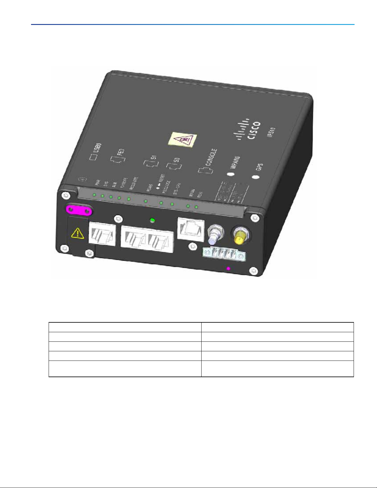
The IR510 DA Gateway works with the CGR1000 series of routers, primarily in the electrical grid to provide a low cost,
low power, small size DA solution. The IR510 DA Gateway (Figure 1 IR510 in IP30 Enclosure, page 3) comes within a
ruggedized IP30 enclosure. The enclosure allows installation of IR510 within outdoor cabinets.
2
Page 3
Draft version 3.0 — Cisco Confidential
IR510 and IR530 Hardware-Cisco IOS
Overview
Figure 1 IR510 in IP30 Enclosure
IR510 System Specifications
Table 1 IR510 Hardware Specifications
Item Description
Dimensions 5.9 x 5 x 1.75 (Inches)
Operating ambient temperature range -40C to +60 (Celsius)
DC Power Supply Supports 12-48Vdc nominal, 9.6-60Vdc maximum range
Reset button Allows factory reset when you press button for
approximately 5 seconds.
3
Page 4

Draft version 3.0 — Cisco Confidential
IR510 and IR530 Hardware-Cisco IOS
Overview
Table 2 IR510 Device Interfaces
Item Description
Alarm port Port has one Isolated input for open and closed relay
QMA Antenna Port 900 MHz ISM band, Omni stick, 24 inch, 5 dBi, N(f), Cisco
RJ45 Fast Ethernet 10/100 port Provides 10/100 Mb/s device connections.
RJ45 RS232-DCE or RS485 port Provides user the option to configure either port interface
detection.
PID ANT-WPAN-OM-OUT-N.
Panel-mounted, 50-ohm connector for connecting the
antenna to the WPAN gateway.
Supports the IR509 antenna (ANT-WPAN-OM-OUT-N)
via software on the same RJ45 port.
RS232 operates in full duplex mode port
RS485 operates in half duplex or full duplex mode.
Use the IoT Field Network Director (FND) 4.1 (and higher)
User Guide to configure the port and provide statistics
about the serial port including bytes sent and received
information.
RS232 Console port To access the console port, remove the front cover.
RS232-DTE port Provides for direct connection to a DCE port. Use the
IoT Field Network Director (FND) 4.1 (and higher) User
Guide to configure the port and get statistics about the
port including bytes sent and bytes received information.
USB-A (LS/FS/HS) Host port Supports the following signaling rates: 1Mb/s (low
speed), 12Mb/s (full speed) and 480 Mb/s (high speed).
Table 3 IR510 LEDs
LED Green Yellow Red
PWR (Power) OK: All Power OK: 12K PSU only ---
SYS (System) Blinking: Master Controller Unit
(MCU) is running system software
CPU (System) Blinking: CPU is actively running
user application
ALM --- --- Solid: Alarm Detected
FE Solid: Ethernet Link Established
Blinking: Ethernet Activity Detected
RS232-DCE Solid: S0 Port is RS232 DCE --- ---
RS485 Solid: S0 Port is RS485 --- ---
RS232-DTE Solid: S1 Port is RS232 DTE --- ---
Blinking: MCU is booting up ---
Blinking: CPU is booting up ---
--- ---
4
Page 5

Draft version 3.0 — Cisco Confidential
IR510 and IR530 Hardware-Cisco IOS
Overview
Table 4 IR510 Product IDs and Accessories
Product ID Description
IR510-OFDM-FCC/K9 Cisco 510 WPAN Industrial Router
IR510-DINRAIL= DIN Rail spare assembly
ANT-UN-MP-OUT-QMA Antenna with QMA connector and 5 ft cable for use with
IR510
ANT-UN-MP-OUT-QMA= Antenna with QMA connector and 5 ft cable for use with
IR510 (Spare)
ANT-WPAN-OM-OUT-N Omni antenna for 900 MHz WPAN (Outdoor)
IR530 Hardware Overview
For details on Environmental Compliance, Immunity, EMC, Safety and Ingress Protection (dust/water) or to confirm any
IR530 Hardware Specifications, please refer to the Cisco IR530 Series Resilient Mesh Range Extenders Data Sheet.
Table 5 IR530 Hardware Specifications
Item Description
Dimensions (W x D x H) 5.2” x 7.23” x 10.37”
Typical weight fully configured 8.4 lbs (3.8 kg)
Pole mount Yes
Operating temperature 40°C to +70°C (-40°F to 158°F) with IEEE 1613 type test
up to 85°C (185°F) for 16 hours
Typical power consumption or dissipation Normal operation: 6W max with BBU charging: 23W max
IEEE 802.15.4 WPAN IEEE 802.15.4g/e/v
Frequency support
Spread spectrum technology OFDM Option 2 802.15.4g
Frequency hopping between up to quantity 31 800 kHz
channels
PHY data rates of 50 kb/s, 200 kbps, 800 kbps, and
1200kbps
Transmitter output (conducted) 28 dBm typical, at 50 kb/s, and 200 kbps
25 dBm typical, at 800 kb/s,
24 dBm typical, at 1200 kb/s,
Antenna connector RF Mesh QMA N connector (female)
RS 232 serial console port 1
Digital alarm inputs 1
Integrated AC/DC power supply input range 85 – 264 VAC, 47 – 63 Hz
Power Consumption 6W (no BBU charging) 20W (BBU charging)
For details on Environmental Compliance, Immunity, EMC, Safety and Ingress Protection (dust/water) or to confirm any
IR530 Hardware Specifications, please refer to the Cisco IR530 Series Resilient Mesh Range Extenders Data Sheet.
5
Page 6

Draft version 3.0 — Cisco Confidential
IR510 and IR530 Hardware-Cisco IOS
Overview
6
Page 7

Draft version 3.0 — Cisco Confidential
IR510 and IR530 Hardware-Cisco IOS
Overview
Table 6 LEDs for IR530
LED Name Definition State
RSSI Measure of power present in the
received radio signal.
WPAN WPAN traffic activity detect. Yellow (Off) / Green (Off): WPAN port is disabled.
SYS Indicates module status. Green (Blinking): Broadcast slot time complete
Yellow (Off) / Green (Off): RSSI less than -105 dBm
Yellow (On) / Green (Off): RSSI is -105 to -95 dBm
Yellow (Off) / Green (Slow Blink): RSSI is -95 to -75 dBm
Yellow (Off) / Green (Fast Blink): RSSI is -75 to -60 dBm
Yellow (Off) / Green (Solid On): RSSI greater than -60 dBm
Yellow (On) / Green (Off): Searching for network.
Yellow (Off) / Green (Slow Blink): WPAN port is up.
Yellow (Off) / Green (Fast Blink): Route is available and
DHCPv6 configuration is starting.
Yellow (Off) / Green (On): Global IPv6 address is available.
Yellow (Blinking): Bootload in process
Yellow (Solid): Software update mode in process
Table 7 IR530 Antennas
Cisco Part Number Description
ANT-WPAN-OM-OUT-N Omni antenna for 900 MHz WPAN, outdoor
For more details on the supported antenna, please refer to the document below:
Connected Grid Antennas Installation Guide
Cable Options
Refer to the Cisco IR530 Series Resilient Mesh Range Extenders Data Sheet for a summary of all supported cables, see
Table 4.
7
Page 8

Draft version 3.0 — Cisco Confidential
IR510 and IR530 Hardware-Cisco IOS
Installation Guidelines
IR530 WPAN RF900 Range Extender (RE) Product IDs
Table 8 IR530 Product IDs and Accessories
Product ID Description
R530-OFDM-FCC/K9 IR530 with 915MHz-WPAN, utility-grade DC power. For
all North and South America except Brazil.
IR530-OFDM-BRZ/K9 IR530 with 915MHz-WPAN, utility-grade DC power. For
Brazil.
IR530-OFDM-ANZ/K9 IR530 with 915MHz-WPAN, utility-grade DC power. For
Australia and New Zealand.
Installation Guidelines
CAUTION : Do not place anything on top of the router that weighs more than 10 pounds (4.5 kilograms), and do not stack
routers on a desktop. Excessive weight on top of the router could damage the chassis.
CAUTION : Do not install the router or power supplies next to a heat source of any kind, including heating vents.
WARNING : In order to comply with FCC radio frequency (RF) exposure limits, antennas for this product should be located
a minimum of 7.9 in (20cm) or more from the body of all persons. Statement 332
WARNING : Read the installation instructions before connecting the system to the power source. Statement 1004
WARNING : Only trained and qualified personnel should be allowed to install, replace, or service this equipment.
Statement 1030
WARNING : No user-serviceable parts inside. Do not open. Statement 1073
WARNING : Ultimate disposal of this product should be handled according to all national laws and regulations. Statement
1040
WARNING : Do not locate the antenna near overhead power lines or other electric light or power circuits, or where it can
come into contact with such circuits. When installing the antenna, take extreme care not to come into contact with such
circuits, because they may cause serious injury or death. For proper installation and grounding of the antenna, please
refer to national and local codes (for example, U.S.:NFPA 70, National Electrical Code, Article 810, Canada: Canadian
Electrical Code, Section 54). Statement 1052
WARNING : This product is not intended to be directly connected to the Cable Distribution System. Additional regulatory
compliance and legal requirements may apply for direct connection to the Cable Distribution System. This product may
connect to the Cable Distribution System ONLY through a device that is approved for direct connection. Statement 1078
Configuring IR510 and IR530 Systems
IoT Field Network Director (IoT-FND) 4.2.x release provides the user interface for IR510 and IR530 configuration as well
as the configuration and management and the CGM-WPAN-OFDM Module.
IoT-FND Configuration Notes
The following guides provide information on installing and configuring the Cisco IR510 and IR530 systems:
Cisco IoT Field Network Director Installation Guide, Release 4.2.x
Cisco IoT Field Network Director User Guide, Release 4.2.x
8
Page 9

Draft version 3.0 — Cisco Confidential
IR510 and IR530 Hardware-Cisco IOS
Configuring IR510 and IR530 Systems
CLI Configuration Notes
Table 9 Summary of New CLI Interface commands for the IR510 and IR530
Command Definition
ieee154 phy-mode <64|96|66|98|144|146|147|149|
150|192>
Defines the IEEE154 phy-mode. Possible options noted
below, default value is 149.
9
Page 10

Draft version 3.0 — Cisco Confidential
IR510 and IR530 Hardware-Cisco IOS
Configuring IR510 and IR530 Systems
10
 Loading...