

Page 1

IR510 WPAN Gateway and IR530 WPAN
Range Extender Hardware Installation Guide
First Published: 2018-06-26
Organization
This guide includes the following sections:
Conventions, page 2 Details on style conventions used in the guide.
Preface, page 2 Provides a general overview of the IR510 and IR530 products. It also
provides important site preparation and safety measures to follow before
installing the system.s
IR510 Installation, page 3 Provides hardware and software specifications, lists Cautions and Warnings
IR530 Series Resilient Mesh Range Extender Installation,
page 16
Configuring IR510 and IR530 Systems, page 26 Provides details on configuring and monitoring system. Includes CLI
Related Documentation, page 26 Provides links to related Cisco products that the IR510 and IR530 can be
to note before physically installing the systems. Provides steps for
unpacking the system and physically installing the system; and details on
how to monitor the systems (such as LEDs).
commands and links to the IoT Field Network Director User Guides that
provides management options for the IR510 platform.
connected to or managed by.
Cisco Systems, Inc. www.cisco.com
1
Page 2

IR510 WPAN Gateway and IR530 WPAN Range Extender Hardware Installation Guide
Conventions
Conventions
This document uses the following conventions.
Conventions Indication
bold font Commands and keywords and user-entered text appear in bold font.
italic font Document titles, new or emphasized terms, and arguments for which you supply values are in italic font.
[ ] Elements in square brackets are optional.
{x | y | z } Required alternative keywords are grouped in braces and separated by vertical bars.
[ x | y | z ] Optional alternative keywords are grouped in brackets and separated by vertical bars.
string A nonquoted set of characters. Do not use quotation marks around the string or the string will include the
quotation marks.
courier font Te rminal sessions and information the system displays appear in courier font.
< > Nonprinting characters such as passwords are in angle brackets.
[ ] Default responses to system prompts are in square brackets.
!, # An exclamation point (!) or a pound sign (#) at the beginning of a line of code indicates a comment line.
Note: Means reader take note. Notes contain helpful suggestions or references to material not covered in the manual.
CAUTION: Means reader be careful. In this situation, you might perform an action that could result in equipment damage or loss of data.
WARNING: IMPORTANT SAFETY INSTRUCTIONS
Means danger. You are in a situation that could cause bodily injury. Before you work on any equipment, be aware of the hazards
involved with electrical circuitry and be familiar with standard prac tice s for preventing accidents. Use the st atement number
provided at the end of each warning to locate its translation in the translated safety warnings that accompanied this device.
CAUTION: Cable distribution system should be grounded (earthed) in accordance with ANSI/NFPA 70, the National Electrical Code
(NEC), article 800, Grounding of Outer Conductive Shield of a Coaxial Cable.
Warning: Only trained and qualified personnel should be allowed to install, replace, or service this equipment. Statement 1030
SAVE THESE INSTRUCTIONS
Regulatory: Provided for additional information and to comply with regulatory and customer requirements.
Preface
Because the IR510 WPAN Gateway (IR510) and IR530 Resilient Mesh Range Extender (IR530 Range Extender) are radio devices, they
are susceptible to common causes of interference that can reduce throughput and range. Follow these basic guidelines to ensure the best
possible performance:
For information on planning and initially configuring your Cisco Resilient Mesh network, refer to the Cisco Wireless Mesh Access
Points, Design and Deployment Guide on Cisco.com.
Review the FCC guidelines for installing and operating outdoor wireless LAN devices at:
https://www.cisco.com/c/en/us/products/collateral/routers/3200-series-rugged-integrated-services-routers-isr/data_sheet_c78-647116
.html
Perform a site survey before beginning the installation.
Install the IR510 WPAN Gateway and IR530 Range Extender in an area where structures, trees, or hills do not obstruct radio signals
to and from the devices.
2
Page 3

IR510 WPAN Gateway and IR530 WPAN Range Extender Hardware Installation Guide
IR510 Installation
The IR510 WPAN Gateway and IR530 Range Extender can be installed at any height, but best throughput is achieved when all the
WP AN gateways and WPAN range extenders are mounted at the same height. We recommend installing the devices no higher than 40
feet to allow support for wireless clients on the ground.
Safety Warning-Hazardous Locations
Before installing this product in a hazardous location, make sure you have read and understood all of the information in the Product
Document of Compliance that shipped with the product.
IR510 Installation
This section describes the IR510 WPAN Gateway and includes the following topics:
IR510 Hardware Overview, page3
IR510 Product IDs and Accessories, page 4
IR510 Cautions and Warnings, page 4
IR510 Hardware Specifications, page 6
IR530 Range Extender Product IDs, page 17
LEDs, page 26
Antenna, page 26
IR510 Hardware Overview
The IR510 operates within a wireless mesh network, providing intelligent control over Cisco Resilient Mesh Endpoints (RMEs) devices
that use Serial (RS232/RS485), USB (LS/FS/HS), or Fast Ethernet (10/100 Fast Ethernet) ports. Additionally, the gateway employs GPS
for time synchronization and location tracking.
The IR510 works with the CGR1000 series of routers, primarily in the electrical grid to provide a low cost, low power, small size DA
solution. The IR510 Gateway (Figure 1 IR510 in IP30 Enclosure, page 7) comes within a ruggedized IP30 enclosure. The enclosure allows
installation of IR510 within outdoor cabinets.
For more details on product features, applications and accessories, refer to:
Cisco IR510 WPAN Industrial Router Data Sheet
3
Page 4

IR510 WPAN Gateway and IR530 WPAN Range Extender Hardware Installation Guide
IR510 Installation
IR510 Product IDs and Accessories
Product ID Description
IR510-OFDM-FCC/K9 Cisco 510 WPAN Industrial Router
IR510-DINRAIL= DIN Rail assembly (spare)
ANT-UN-MP-OUT-QMA Antenna with QMA connector and 5 ft. cable for use with IR510
ANT-UN-MP-OUT-QMA= Antenna with QMA connector and 5 ft. cable for use with IR510 (spare)
ANT-WPAN-OM-OUT-N Omni antenna for 900MHz WPAN (Outdoor)
IR510 Cautions and Warnings
CAUTION: Do not place anything on top of the router that weighs more than 10 pounds (4.5 kilograms), and do not stack routers on a
desktop. Excessive weight on top of the router could damage the chassis.
CAUTION: Do not install the router or power supplies next to a heat source of any kind, including heating vents.
CAUTION: This equipment is intended to be grounded to comply with emission and immunity requirements. Ensure that the switch
functional ground lug is connected to earth ground during normal use. Statement 1064
WARNING : Read the installation instructions before connecting the system to the power source. Statement 1004
WARNING: This product relies on the building’s instal lation for short- circuit (over current) protection. Ensure that the protective device is
rated not greater than: 5 Amps. Statement 1005
WARNING: This unit is intended for installation in restricted access areas. A restricted access area can be accessed only through the use of
a special tool, lock and key, or other means of security. Statement 1017
WARNING: Only trained and qualified personnel should be allowed to install, replace, or service this equipment. Statement 1030
WARNING: Connect the unit only to DC power source that complies with the Safety Extra-Low Voltage (SEL V) requirements in IEC 60950
based safety standards. Statement 1033
WARNING: Ultimate disposal of this product should be handled according to all national laws and regulations. Statement 1040
WARNING: Do not locate the antenna near overhead power lines or other electric light or power circuits, or where it can come into contact
with such circuits. When installing the antenna, take extreme care not to come into contact with such circuits, because they may cause
serious injury or death. For proper installation and grounding of the antenna, please refer to national and local codes (for example,
U.S.:NFPA 70, National Electrical Code, Article 810, Canada: Canadian Electrical Code, Section 54). Statement 1052
WARNING: No user-serviceable parts inside. Do not open. Statement 1073
WARNING : This product is not intended to be directly connected to the Cable Distribution System. Additional regulatory compliance and
legal requirements may apply for direct connection to the Cable Distribution System. This product may connect to the Cable Distribution
System ONLY through a device that is approved for direct connection. Statement 1078
Additional Information for Installation in a Hazardous Environment (IR510 Only)
CAUTION: This equipment is only suitable for use in Class I, Division 2, Groups A, B, C, D, or nonhazardous locations.
CAUTION: For the WPAN gateway, connect only to an NEC Class 2 power source or limited power source as defined by IEC 60950-1.
WARNING: Exposure to some chemicals could degrade the sealing properties of materials used in the sealed relay device. Statement 381
WARNING: Failure to securely tighten the captive screws can result in an electrical arc if the connector is accidentally removed. Statement
397
4
Page 5

IR510 WPAN Gateway and IR530 WPAN Range Extender Hardware Installation Guide
IR510 Installation
WARNING: When you connect or disconnect the power and/or alarm connector with power applied, an electrical arc can occur. This could
cause an explosion in hazardous area installations. Be sure that all power is removed from the switch and any other circuits. Be sure that
power cannot be accidentally turned on or verify that the area is nonhazardous before proceeding. Statement 1058
WARNING: In switch installations in a hazardous location, the DC power source could be located away from the vicinity of the switch.
Before performing any of the following procedures, locate the DC circuit to ensure that the power is removed and cannot be turned on
accidentally, or verify that the area is nonhazardous before proceeding. Statement 1059
WARNING: This equipment is supplied as “open type” equipment. It must be mounted within an enclosure that is suitably designed for
those specific environmental conditions that will be present and appropriately designed to prevent personal injury resulting from
accessibility to live parts. The interior of the enclosure must be accessible only by the use of a tool. The enclosure must meet IP 54 or NEMA
type 4 minimum enclosure rating standards. Statement 1063
WARNING: Use twisted-pair supply wires suitable for 86°F (30°C) above surrounding ambient temperature outside the enclosure.
Statement 1067
WARNING: This equipment is intended for use in a Pollution Degree 2 industrial environment, in over-voltage Category II applications (as
defined in IEC publication 60664-1), and at altitudes up to 2000 meters without derating Statement 1068
WARNING: When used in a Class I, Division 2, hazardous location, this equipment must be mounted in a suitable enclosure with a proper
wiring method that complies with the governing electrical codes Statement 1069
WARNING: Do not connect or disconnect cables to the ports while power is applied to the switch or any device on the network because an
electrical arc can occur. This could cause an explosion in hazardous location installations. Be sure that power is removed from the switch
and cannot be accidentally be turned on, or verify that the area is nonhazardous before proceeding. Statement 1070
WARNING: Explosion Hazard—Do not connect or disconnect wiring while the field-side power is on; an electrical arc can occur . This could
cause an explosion in hazardous location installations. Be sure that power is removed or that the area is nonhazardous before proceeding.
Statement 1081
WARNING: Explosion Hazard - The area must be known to be nonhazardous before installing, servicing, or replacing the unit. Statement
1082
WARNING: Explosion Hazard—Substitution of components may impair suitability for Class I, Division 2/Zone 2. Statement 1083
North American Hazardous Location Approval for WPAN Gateway
English Products marked “Class I, Div 2, GP A, B, C, D” are suitable for use in Class I Division 2 Groups A, B,
C, D, Hazardous Locations and nonhazardous locations only. Each product is supplied with markings on
the rating nameplate indicating the hazardous location temperature code. When combining products within
a system, the most adverse temperature code (lowest “T” number) may be used to help determine the
overall temperature code of the system. Combinations of equipment in your system are subject to
investigation by the local Authority Having Jurisdiction at the time of installation.
French Informations sur l'utilisation de cet équipement en environnements dangereux:
Les produits marqués "Class I, Div 2, GP A, B, C, D" ne conviennent qu'à une utilisation en
environnements de Classe I Division 2 Groupes A, B, C, D dangereux et non dangereux. Chaque produit
est livré avec des marquages sur sa plaque d'identification qui indiquent le code de température pour les
environnements dangereux. Lorsque plusieurs produits sont combinés dans un système, le code de
température le plus défavorable (code de température le plus faible) peut être utilisé pour déterminer le
code de température global du système. Les combinaisons d'équipements dans le système sont sujet tes à
inspection par les autorités locales qualifiées au moment de l'installation
Unpacking the IR510
Note: When you are unpacking the IR510, do not remove the foam blocks attached to the antenna connectors. The foam protects the antenna
connectors during installation.
5
Page 6

IR510 WPAN Gateway and IR530 WPAN Range Extender Hardware Installation Guide
IR510 Installation
To unpack the IR510:
1. Open the shipping container and carefully remove the contents.
2. Return all packing materials to the shipping container, and save them.
3. Ensure that all items listed in “Package Content s” section are included in the shipment. If any item is damaged or missing, notify your
sales representative.
Package Contents
IR510
Grounding lug with 2 screws
Mechanical kit, with 2 mounting brackets and 4 screws
Pointer cards for product and compliance documentation
IR510 Hardware Specifications
IMPORTANT: Be sure to review both the IR510 Cautions and Warnings, page 4 and Additional Information for Installation in a Hazardous
Environment (IR510 Only), page 4 before mounting the IR510.
This section includes the following sections:
IR510 Hardware Specifications, page 8
IR510 Mounting Options, page 11
Connecting Protective Ground and Power for IR510, page 14
6
Page 7
IR510 WPAN Gateway and IR530 WPAN Range Extender Hardware Installation Guide
IR510 Installation
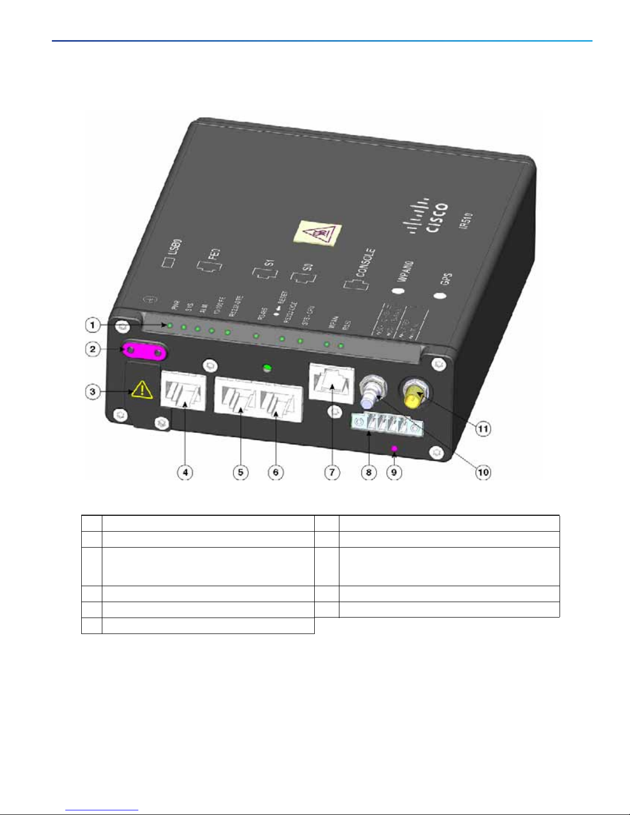
Figure 1 IR510 in IP30 Enclosure
Table 1 IR510 Front Panel
1 Status LEDs (see Table 4 on page 8) 7 Console port (RJ45 10/100 Fast Ethernet port)
2 Ground connection point 8 DC power and alarm connector
3 USB 2.0 port (covered by Caution panel). The USB
port has access to RS232, RJ45 serial ports and Fast
Ethernet ports)
4 10/100 Fast Ethernet port 10 WPAN antenna connector
5 RS232 DTE port 11 GPS antenna connector
6 RS232 DCE or RJ485 DCE selectable port
9 Reset button
7
Page 8

IR510 WPAN Gateway and IR530 WPAN Range Extender Hardware Installation Guide
IR510 Installation
IR510 Hardware Specifications
Table 2 IR510 Hardware Specifications
Item Description
Dimensions 5.9 x 5 x 1.75 (Inches)
Operating ambient temperature range -40C to +60 (Celsius)
DC Power Supply Supports 12-48Vdc nominal, 9.6-60Vdc maximum range
Reset button Allows factory reset when you press button for approximately 5
seconds.
Table 3 IR510 Device Interfaces
Item Description
Alarm port Port has one Isolated input for open and closed relay detection.
QMA Antenna Port 900 MHz ISM band, Omni stick, 24 inch, 5 dBi, N(f), Cisco PID
ANT-WPAN-OM-OUT-N.
Panel-mounted, 50-ohm connector for connecting the antenna to
the WPAN gateway.
Supports the IR509 antenna (ANT-WPAN-OM-OUT-N)
RJ45 Fast Ethernet 10/100 port Provides 10/100 Mb/s device connections.
RJ45 RS232-DCE or RS485 port Provides user the option to configure either port interface via
software on the same RJ45 port.
RS232 operates in full duplex mode port
RS485 operates in half duplex or full duplex mode.
Use the IoT Field Network Director (FND) 4.1 (and higher) User
Guide to configure the port and provide statistics about the serial
port including bytes sent and received information.
RS232 Console port To access the console port, remove the front cover.
RS232-DTE port Provides for direct connection to a DCE port. Use the
IoT Field Network Director (FND) 4.1 (and higher) User Guide to
configure the port and get statistics about the port including bytes
sent and bytes received information.
USB-A (LS/FS/HS) Host port Supports the following signaling rates: 1Mb/s (low speed), 12Mb/s
(full speed) and 480 Mb/s (high speed).
Table 4 IR510 LEDs
LED Green Yellow Red
PWR (Power) OK: All Power OK: 12K PSU only --SYS (System) Blinking: Master Controller Unit
(MCU) is running system software
CPU (System) Blinking: CPU is actively running user
application
ALM --- --- Solid: Alarm Detected
Blinking: MCU is booting up ---
Blinking: CPU is booting up ---
8
Page 9

IR510 WPAN Gateway and IR530 WPAN Range Extender Hardware Installation Guide
IR510 Installation
Table 4 IR510 LEDs
LED Green Yellow Red
FE Solid: Ethernet Link Established
Blinking: Ethernet Activity Detected
RS232-DCE Solid: S0 Port is RS232 DCE --- --RS485 Solid: S0 Port is RS485 --- --RS232-DTE Solid: S1 Port is RS232 DTE --- ---
--- ---
Mounting the IR510 - Airflow Requirements for Rack and DIN Rail
Airflow around the WPAN gateway must be unrestricted. The gateway dimensions (height x width x depth) are 1.125 x 4.0 x 5.0 in. (2.86
x 10.16 x 12.7 cm). To prevent the WPAN gateway from overheating, you must provide the following minimum clearances (see Figures.
Contact your Cisco Technical Assistance Centre (TAC) if tighter spacings are required.
- Sides: 1.0 in. (25.4 mm)
- Front: 1.0 in. (25.4 mm)
- Rear: 1.0 in. (25.4 mm)
- Top : 1.0 in. (25.4 mm)—the device can be installed in a 1.25” tall slot, but the mounting surface must have thermal conductive properties
equivalent to or better then 302 stainless steel (16.3 W/m-k).
9
Page 10

IR510 WPAN Gateway and IR530 WPAN Range Extender Hardware Installation Guide
IR510 Installation
Figure 2 IR510 Mounting Clearance Shown for Optimum Airflow- Rack Mount
10
Page 11

IR510 WPAN Gateway and IR530 WPAN Range Extender Hardware Installation Guide
IR510 Installation
Figure 3 IR510 Mounting Clearance Shown for Optimum Airflow- DIN Rail Mount
IR510 Mounting Options
There are two mounting options for IR510: Rack (Figure 4 on page 12) and DIN Rail (Figure 5 on page 13). Mounting hardware is shipped
in the IR510 Accessory Kit (53-100793-01).
11
Page 12

IR510 WPAN Gateway and IR530 WPAN Range Extender Hardware Installation Guide
IR510 Installation
I
Table 5 Rack Mounting Kit
1 Mounting Screws - Quantity of 4
2 Mounting Brackets- Quantity of 2
Figure 4 Attaching Mounting Brackets to IR510 to Support Rack Mount
Installation Steps for Mounting Brackets
1. Use a ratcheting torque screwdriver to tighten the 4 screws and 2 mounting brackets to the bottom of the IR510 with a torque of
8-11in-lbs.
Note: For rear rack mounting, use the 8-32 holes with a max depth of .25.
Table 6 DIN Rail Mounting Kit
1 DIN bracket assembly 3 Release tab
2 Spring Cover
12
Page 13

IR510 WPAN Gateway and IR530 WPAN Range Extender Hardware Installation Guide
IR510 Installation
Figure 5 Attaching DIN Rail Mounting IR510 Hardware
Installation Steps for DIN Rail Kit
13
Page 14

IR510 WPAN Gateway and IR530 WPAN Range Extender Hardware Installation Guide
300622
1 2
IR510 Installation
1. Remove Spring Cover from DIN Bracket assembly (Item 2 in Figure 5).Set aside the 4 screws in a safe plac e.
2. Attach DIN Bracket assembly (Item 1 in Figure 5) to back of IR510 with seven (7) M3 screws using a torque screwdriver and a torque
of 5 to 7 inch lbs.
3. Attach 8th M3 screw by pushing up on Release Latch (Item 3 in Figure 5) to reveal bottom screw hole.
4. Attach Spring Cover back onto DIN Rail using the 4 screws that were originally used to attach the two items.
Connecting Protective Ground and Power for IR510
The accessory kit (Figure 6) which ships with the IR510, includes 2 ground screws and a tabular ground lug to provide protective ground
for the IR510. Note: You must provide the 14-to-16 AWG ground wire. It is not included in the kit.
Figure 6 Grounding Accessory Kit
1 Grounding lug
2 Screws x 2
CAUTION To make sure that the equipment is reliably connected to earth ground, follow the steps below and use 14-to-16 AW G wire.
2
CAUTION Use at least a 4 mm
To ground the IR510 to earth ground by using the 2 ground screws, follow these steps:
5. Use a wire stripping tool to strip the 14-to-16 AWG ground wire to 0.22 in. (5.56 mm).
6. Insert the ground wire into the ground lug, and using a crimping tool, crimp the ground lug to the wire.
7. Slide the two ground screws through the ground lug.
8. Insert the two ground screws into the functional ground screw openings found on the upper, left-hand side of the front panel of the
IR510 (Figure 7).
9. Use a ratcheting torque screwdriver to tighten the ground screws to the IR510 front panel. The torque should not exceed 8-11 in-lb (0.9
to 1.2 N-m).
10. Attach the other end of the ground wire to a grounded bare metal surface such as a ground bus, a grounded DIN rail, or a grounded
bare rack.
conductor to connect the two external ground screws to the IR510.
14
Page 15

391216
IR510 WPAN Gateway and IR530 WPAN Range Extender Hardware Installation Guide
IR510 Installation
Figure 7 Installing the Ground Lug Screw
Power and Alarm Connector for IR510
IR510 requires DC power. You connect the DC power and alarm con nections to the IR510 through the Power and Alarm Connector found
on the far-right front panel of the IR510 above the Reset Button. (Figure 7). The power connector labeling is on the connector (Figure 8).
Ta ble7 on page 16 shows the power and alarm connectors for IR510.
Figure 8 IR510 Power and Alarm Connector
I
15
Page 16

IR510 WPAN Gateway and IR530 WPAN Range Extender Hardware Installation Guide
IR530 Series Resilient Mesh Range Extender Installation
Table 7 IR510 Power and Alarm Connector Pin outs
Pin Label Signal Description
1 V Positive DC power connection
2 RT Return DC power connection
3 A Alarm Reference or Alarm IN
4 A Alarm Reference or Alarm IN
IR530 Series Resilient Mesh Range Extender Installation
This section describes the Cisco Industrial Router 530 (IR530) Series Resilient Mesh Range Extender and includes the following topics:
Hardware Overview, page 16
IR530 Range Extender Cautions and Warnings, page 18
IR530 Range Extender Hardware Specifications, page 18
Mounting the IR530 Range Extender, page 20
Grounding the IR530 Range Extender, page 22
Hardware Overview
The Cisco IR530 Resilient Mesh Range Extender (IR530 Range Extender) provides unlicensed 902-928MHz, ISM-band IEEE
802.15.4g/e/v Wireless Personal-Area Network (WPAN) communications to diverse Internet of things (IoT) applications. It extends the
range of the RF wireless mesh network, providing longer reach between WP AN endpoints and other WPAN networks. There are two IR500
Mesh Range Extender products in the IR500 family: The IR529 and IR530. IR530 represents a high performance, new generation of the
Cisco RF Mesh range extender.
The IR530 Range Extenders take full advantage of Cisco networking expertise in IPv6, security. It provides an open, high performance RF
mesh solution based on the following standards:
IEEE 802.15.4 g/e/v
IETF 6LoWPAN
IETF Routing Protocol for Low Power and Lossy Networks (RPL)
IETF Constrained Application Protocol (CoAP).
For details on Software Specifications, Environmental Compliance, Immunity, EMC, Safety and Ingress Protection (dust/water) or to
confirm any IR530 specifications, please refer to:
Cisco IR530 Series Resilient Mesh Range Extenders Data Sheet.
16
Page 17

IR510 WPAN Gateway and IR530 WPAN Range Extender Hardware Installation Guide
IR530 Series Resilient Mesh Range Extender Installation
Figure 9 IR530 - Bottom View
Table 8 IR530 Components
1 Antenna port 4 Ground
2 System LED 5 Vent
3 AC input 6 Console Port Access
IR530 Range Extender Product IDs
Note: Y ou can order the IR530 with a single or dual antenna and a battery. For IR530 part numbers for systems with batteries and the latest
regional support, refer to the data sheet.
17
Page 18

IR510 WPAN Gateway and IR530 WPAN Range Extender Hardware Installation Guide
IR530 Series Resilient Mesh Range Extender Installation
Table 9 IR530 Product IDs
Product ID Description
IR530-OFDM-FCC/K9 IR530 with 915MHz-WPAN, utility-grade DC power. For all
North and South America except Brazil.
IR530-OFDM-BRZ/K9 IR530 with 915MHz-WPAN, utility-grade DC power. For Brazil.
IR530-OFDM-ANZ/K9 IR530 with 915MHz-WPAN, utility-grade DC power. For
Australia and New Zealand.
IR530 Range Extender Cautions and Warnings
CAUTION : Do not place anything on top of the router that weighs more than 10 pounds (4.5 kilograms), and do not stack routers on a
desktop. Excessive weight on top of the router could damage the chassis.
CAUTION : Do not install the router or power supplies next to a heat source of any kind, including heating vents.
WARNING : Read the installation instructions before connecting the system to the power source. Statement 1004
WARNING : This product relies on the building’s installation for short-circuit (over current) protection. Ensure that the protective device is
rated not greater than: 5 Amps. Statement 1005
WARNING :This unit is intended for installation in restricted access areas. A restricted access area can be accessed only through the use of
a special tool, lock and key, or other means of security. Statement 1017
WARNING :This equipment must be grounded. Never defeat the ground conductor or operate the equipment in the absence of a suitably
installed ground conductor. Contact the appropriate electrical inspection authority or an electrician if you are uncertain that suitable
grounding is available. Statement 1024
WARNING : Only trained and qualified personnel should be allowed to install, replace, or service this equipment. Statement 1030
WARNING : Ultimate disposal of this product should be handled according to all national laws and regulations.
Statement 1040
WARNING :To prevent the system from overheating, do not operate it in an area that ex ce eds the maximum recommended ambient
temperature of: 60C Statement 1047
WARNING : Do not locate the antenna near over head power lines or other electric light or power circuits, or where it can come into cont act
with such circuits. When installing the antenna, take extreme care not to come into contact with such circuits, because they may cause
serious injury or death. For proper installation and grounding of the antenna, please refer to national and local codes (for example,
U.S.:NFPA 70, National Electrical Code, Article 810, Canada: Canadian Electrical Code, Section 54). Statement 1052
WARNING : No user-serviceable parts inside. Do not open. Statement 1073
WARNING : This product is not intended to be directly connected to the Cable Distribution System. Additional regulatory compliance and
legal requirements may apply for direct connection to the Cable Distribution System. This product may connect to the Cable Distribution
System ONLY through a device that is approved for direct connection. Statement 1078
IR530 Range Extender Hardware Specifications
Ta ble 10 on page 19 provides a highlight of the hardware specifications. For more details on product offerings such as antennas, cables, and
RF accessories as well as software specific ations, complia nce, immun ity, emissions, safety and ingress protections (dust and water), please
refer to the Cisco IR530 Series Resilient Mesh Range Extenders Data Sheet.
18
Page 19

IR510 WPAN Gateway and IR530 WPAN Range Extender Hardware Installation Guide
IR530 Series Resilient Mesh Range Extender Installation
Table 10 IR530 Hardware Specifications
Item Description
Dimensions (W x D x H) 5.2” x 7.23” x 10.37”
Typical weight fully configured 8.4 lbs (3.8 kg)
Pole mount Yes
Operating temperature 40°C to +70°C (-40°F to 158°F) with IEEE 1613 type test up to 85°C (185°F) for 16 hours
Typical power consumption or
dissipation
IEEE 802.15.4 WPAN IEEE 802.15.4g/e/v
Frequency support 902-928 MHz (and subset of it to comply with country’s regulations)
Normal operation: 6W max
With BBU charging: 23W max
North America- ISM: 902-928 MHz
Australia: 915-928 MHz
Brazil: 902-907.5, 915-928 MHz
Spread spectrum technology Frequency hopping: OFDM: 31 channels, 800kHz channel spacing. 2FSK: 64 channels,
400kHz channel spacing. 2FSK and OQPSK:129 channels, 200kHz channel spacing
Frequency hopping between up to quantity 31 800 kHz channels
PHY data rates of 50 kb/s, 200 kbps, 800 kbps, and 1200kbps
Transmitter output (conducted) 28 dBm typical, at 50 kb/s, and 200 kbps
25 dBm typical, at 800 kb/s,
24 dBm typical, at 1200 kb/s,
Antenna connector RF Mesh QMA N connector (female)
RS 232 serial console port 1
Digital alarm inputs 1
Integrated AC/DC power supply
input range
Power Consumption 6W (no BBU charging) 20W (BBU charging)
85 – 264 VAC, 47 – 63 Hz
Unpacking the IR530 Range Extender
Package Contents
IR530 Resilient Mesh Range Extender
Power cable
Ground lug and screws
Pole mounting bracket
Note: When you unpack the IR530, do not remove the foam blocks attached to the antenna connectors. The foam protects the antenna
connectors during installation.
19
Page 20

IR510 WPAN Gateway and IR530 WPAN Range Extender Hardware Installation Guide
IR530 Series Resilient Mesh Range Extender Installation
To unpack the IR530 Resilient Mesh Range Extender:
1. Open the shipping container and carefully remove the contents.
2. Return all packing material to the shipping container and save it.
3. Verify that all items listed in the Package Contents sect ion are included in the shipment. If any item is damaged or missing, notify your
sales representative.
Mounting the IR530 Range Extender
You can mount the IR530 on a pole using a mounting bracket. To attach the mounting bracket to the pole, see Figure 10.
To attach the IR30 to the mounting bracket, see Figure 11.
IR530 Range Extender Orientation
When mounting the IR530 Range Extender on a pole, ensure that the extender is oriented with the antenna pointing downwards (see
Figure 11). Note: After you attach the IR530 to the mounting bracket, you must properly ground the unit before connecting power cables.
See Grounding the IR530 Range Extender, page 22.
Attaching the IR530 Range Extender to the Pole Mounting Bracket
Use the four screws and washers that ship with the product to attach the IR530 the mounting bracket (Figure 11) using a torque of 6 to 7
ft-lbs.
20
Page 21

1
2
3
4
5
6
391281
IR510 WPAN Gateway and IR530 WPAN Range Extender Hardware Installation Guide
IR530 Series Resilient Mesh Range Extender Installation
Figure 10 Attaching IR530 Mounting Bracket to Pole
Table 11 Mounting Kit Components
1Pole 4Washer
2 U bolt (part number 62-2766-01) 5 Spring loaded washer
3 Pole mounting bracket (part number 700-45850-01) 6 Nut
Figure 11 Attaching the IR530 Range Extender to the Pole Mounting Bracket
21
Page 22

IR510 WPAN Gateway and IR530 WPAN Range Extender Hardware Installation Guide
IR530 Series Resilient Mesh Range Extender Installation
Table 12 IR530 Mounting Components
1 Screws (4) to attach IR530 to mounting bracket
2 Mounting holes (4)
Grounding the IR530 Range Extender
The accessory kit that ships with the IR530, includes one tabular ground lug and two ground screws to provide protective ground for the
IR530 (Figure 12). You must provide the 6 AWG ground wire. It is not included in the kit.
Note: You must ground the IR530 before you connect power cables.
22
Page 23

300622
1 2
391287
IR510 WPAN Gateway and IR530 WPAN Range Extender Hardware Installation Guide
IR530 Series Resilient Mesh Range Extender Installation
Figure 12 Grounding Accessory Kit
1. To ground the range extender, use a crimping tool to crimp the 6-gauge ground wire to the grounding lug. Figure 13
Figure 13 Crimping the Ground Lug
2. Connect the grounding lug to the IR530 WPAN Range Extender ground connection point using the supplied screws (Figure 14).
Tighten the screws to 10 to 12 foot-pounds of torque.
3. If necessary , strip the other end of the grou nd wire and connect it to a reliable ea rth ground, such as a grounding rod or an appropriate
grounding point on a pole that is grounded.
23
Page 24

IR510 WPAN Gateway and IR530 WPAN Range Extender Hardware Installation Guide
391288
1
IR530 Series Resilient Mesh Range Extender Installation
Figure 14 Grounding Lug Connects to IR530 Range Extender Ground (GND)
Table 13
1 Grounding cable
Wiring the IR530 Range Extender AC Power
When wiring the range extender AC power, ensure that the following conditions are met:
AC power can be readily and conveniently removed from the IR530 range extender. The power should not be removed by
disconnecting the AC power connector on the unit. It should be removed by disabling AC power at the power circuit.
You must protect AC power plugs and AC receptacles from water and other outdoor elements. Y ou can use a UL-listed water proofing
enclosure suitable for covering the AC receptacle and AC power plug that supplies power to the unit, as described in Article 406 of the
National Electric Code (NEC).
When you install the unit outdoors, or in a wet or damp location, the AC branch circuit that powers the unit should have ground fault
protection (GFCI), as required by Article 210 of the NEC.
If the power cord goes through a metal cover, a bushing should be installed to prevent fraying of the cord. When using a strain relief
bushing, you should follow these recommendations:
— Use properly sized parts
— Use bushings that are safety certified
— Use parts that are suitable for outdoor installation
Ensure that the user-supplied AC power plug is certified for outdoor use and has a minimum IP67 rating.
AC Power Cable
The IR530 range extender supports the Cisco AC power cable that ships with the unit. One end of the cable has the range extender AC power
connector and the other end is unfinished and you must provide and attach an AC power plug or terminate th e cable at your installation sit e.
The AC power plug or termination method you use depends on the power source, such as a junction box, at your site.
If you attach an AC power plug:
24
Page 25

300595
Notch
IR510 WPAN Gateway and IR530 WPAN Range Extender Hardware Installation Guide
IR530 Series Resilient Mesh Range Extender Installation
Use a plug that complies with local and national electrical codes.
Verify the connection between the cable and plug is weatherproof.
Note: You might have to cut the cable if a specific cable length is needed for your installation.
CAUTION: Ensure that the power source is OFF before connecting or disconnecting the power cord wires from the power source.
CAUTION: To attach the appropriate connector the AC power cable, follow the manual or other instructions provided by the electrical
equipment vendor, ensuring that you comply with the electrical codes for your installation location.
Figure 15 IR530 Range Extender Connector
Table 14
Pin Signal Name Signal Description
1L AC line
2 N AC neutral
3 Chassis Chassis ground
Connecting to AC Power
To connect the IR530 Range Extender power connector in to an AC power source:
1. Always connect the IR530 Range Extender end of the cable first. When removing the AC power connector, always disconnect the
IR530 Range Extender end of the cable last.
2. Verify that the unit is grounded as described in the “Grounding the WP AN Range Extender” section on page 2-24.
3. Turn off power to the AC power source at the designated circuits.
4. Align the notch in the IR530 Range Extender power cable connector with the key in the range extender AC power connector , and push
the cable connector into the range extender connector. When the cable connector is fully seated, rotate the cable connector ring
clockwise until it is hand-tightened to a torque of 6-7 ft-lbs (8.13-9.49 N-m).
5. Confirm the WPAN antennas are connected to the range extender before you apply power to the range extender.
6. Connect the other end of the AC power cable to the power source, using the instructions that came with the connecting device.
7. Turn on AC power at the designated circuits. The range extender will power on and boot the software image.
25
Page 26

IR510 WPAN Gateway and IR530 WPAN Range Extender Hardware Installation Guide
Configuring IR510 and IR530 Systems
LEDs
Table 15 LEDs for IR530 Range Extender
LED Name Definition State
RSSI Measure of power present in the received
radio signal.
WPAN WPAN traffic activity detect. Yellow (Off) / Green (Off): WPAN port is disabled.
SYS Indicates module status. Green (Blinking): Broadcast slot time complete
Yellow (Off) / Green (Off): RSSI less than -105 dBm
Yellow (On) / Green (Off): RSSI is -105 to -95 dBm
Yellow (Off) / Green (Slow Blink): RSSI is -95 to -75 dBm
Yellow (Off) / Green (Fast Blink): RSSI is -75 to -60 dBm
Yellow (Off) / Green (Solid On): RSSI greater than -60 dBm
Yellow (On) / Green (Off): Searching for network.
Yellow (Off) / Green (Slow Blink): WPAN port is up.
Yellow (Off) / Green (Fast Blink): Route is available and DHCPv6
configuration is starting.
Yellow (Off) / Green (On): Global IPv6 address is available.
Yellow (Blinking): Bootload in process
Yellow (Solid): Software update mode in process
Antenna
IR530 antenna options are noted in the table below.
Cisco Part Number Description
ANT-WPAN-OM-OUT-N Omni antenna for 900 MHz WPAN, outdoor
For more details on the supported antenna, please refer to the document below:
Connected Grid Antennas Installation Guide
Cable Options
Refer to the Cisco IR530 Series Resilient Mesh Range Extenders Data Sheet for a summary of all supported cables.
Configuring IR510 and IR530 Systems
IoT Field Network Director (IoT -FND) 4.2.x release (and later) provides the user interface for IR510 configuration. Refer to the “Managing
Cisco IR510 WPAN Industrial Routers” section within the “Managing Devices” chapter.
Related Documentation
Cisco IoT Field Network Director User Guide, Release 4.2.x
Cisco Connected Grid WPAN Module for CGR 1000 Series Installation and Cisco Resilient Mesh Configuration Guide (Cisco IOS)
26
Page 27

IR510 WPAN Gateway and IR530 WPAN Range Extender Hardware Installation Guide
Related Documentation
Connected Grid Module (CGM) WPAN-OFDM-FCC Module - Cisco IOS
Release Notes for Cisco Resilient Mesh Release 5.7.27
Release Notes for Cisco Resilient Mesh Release 5.6.21
Cisco 1120 Connected Grid Router Hardware Installation Guide
Cisco 1240 Connected Grid Router Hardware Installation Guide
27
Page 28

IR510 WPAN Gateway and IR530 WPAN Range Extender Hardware Installation Guide
Related Documentation
28
 Loading...