

Page 1

Cisco Intrusion Prevention System Appliance and Module Installation Guide for IPS 7.1
Americas Headquarters
Cisco Systems, Inc.
170 West Tasman Drive
San Jose, CA 95134-1706
USA
http://www.cisco.com
Tel: 408 526-4000
800 553-NETS (6387)
Fax: 408 527-0883
Text Part Number: OL-24002-01
Page 2

THE SPECIFICATIONS AND INFORMATION REGARDING THE PRODUCTS IN THIS MANUAL ARE SUBJECT TO CHANGE WITHOUT NOTICE. ALL
STATEMENTS, INFORMATION, AND RECOMMENDATIONS IN THIS MANUAL ARE BELIEVED TO BE ACCURATE BUT ARE PRESENTED WITHOUT
WARRANTY OF ANY KIND, EXPRESS OR IMPLIED. USERS MUST TAKE FULL RESPONSIBILITY FOR THEIR APPLICATION OF ANY PRODUCTS.
THE SOFTWARE LICENSE AND LIMITED WARRANTY FOR THE ACCOMPANYING PRODUCT ARE SET FORTH IN THE INFORMATION PACKET THAT
SHIPPED WITH THE PRODUCT AND ARE INCORPORATED HEREIN BY THIS REFERENCE. IF YOU ARE UNABLE TO LOCATE THE SOFTWARE LICENSE
OR LIMITED WARRANTY, CONTACT YOUR CISCO REPRESENTATIVE FOR A COPY.
The following information is for FCC compliance of Class A devices: This equipment has been tested and found to comply with the limits for a Class A digital device, pursuant
to part 15 of the FCC rules. These limits are designed to provide reasonable protection against harmful interference when the equipment is operated in a commercial
environment. This equipment generates, uses, and can radiate radio-frequency energy and, if not installed and used in accordance with the instruction manual, may cause
harmful interference to radio communications. Operation of this equipment in a residential area is likely to cause harmful interference, in which case users will be required
to correct the interference at their own expense.
The following information is for FCC compliance of Class B devices: This equipment has been tested and found to comply with the limits for a Class B digital device, pursuant
to part 15 of the FCC rules. These limits are designed to provide reasonable protection against harmful interference in a residential installation. This equipment generates,
uses and can radiate radio frequency energy and, if not installed and used in accordance with the instructions, may cause harmful interference to radio communications.
However, there is no guarantee that interference will not occur in a particular installation. If the equipment causes interference to radio or television reception, which can be
determined by turning the equipment off and on, users are encouraged to try to correct the interference by using one or more of the following measures:
• Reorient or relocate the receiving antenna.
• Increase the separation between the equipment and receiver.
• Connect the equipment into an outlet on a circuit different from that to which the receiver is connected.
• Consult the dealer or an experienced radio/TV technician for help.
Modifications to this product not authorized by Cisco could void the FCC approval and negate your authority to operate the product.
The Cisco implementation of TCP header compression is an adaptation of a program developed by the University of California, Berkeley (UCB) as part of UCB’s public
domain version of the UNIX operating system. All rights reserved. Copyright © 1981, Regents of the University of California.
NOTWITHSTANDING ANY OTHER WARRANTY HEREIN, ALL DOCUMENT FILES AND SOFTWARE OF THESE SUPPLIERS ARE PROVIDED “AS IS” WITH
ALL FAULTS. CISCO AND THE ABOVE-NAMED SUPPLIERS DISCLAIM ALL WARRANTIES, EXPRESSED OR IMPLIED, INCLUDING, WITHOUT
LIMITATION, THOSE OF MERCHANTABILITY, FITNESS FOR A PARTICULAR PURPOSE AND NONINFRINGEMENT OR ARISING FROM A COURSE OF
DEALING, USAGE, OR TRADE PRACTICE.
IN NO EVENT SHALL CISCO OR ITS SUPPLIERS BE LIABLE FOR ANY INDIRECT, SPECIAL, CONSEQUENTIAL, OR INCIDENTAL DAMAGES, INCLUDING,
WITHOUT LIMITATION, LOST PROFITS OR LOSS OR DAMAGE TO DATA ARISING OUT OF THE USE OR INABILITY TO USE THIS MANUAL, EVEN IF CISCO
OR ITS SUPPLIERS HAVE BEEN ADVISED OF THE POSSIBILITY OF SUCH DAMAGES.
Cisco and the Cisco logo are trademarks or registered trademarks of Cisco and/or its affiliates in the U.S. and other countries. To view a list of Cisco trademarks, go to this
URL: www.cisco.com/go/trademarks. Third-party trademarks mentioned are the property of their respective owners. The use of the word partner does not imply a partnership
relationship between Cisco and any other company. (1110R)
Any Internet Protocol (IP) addresses used in this document are not intended to be actual addresses. Any examples, command display output, and figures included in the
document are shown for illustrative purposes only. Any use of actual IP addresses in illustrative content is unintentional and coincidental.
Cisco Intrusion Prevention System Appliance and Module Installation Guide for IPS 7.1
© 2010-2013 Cisco Systems, Inc. All rights reserved.
Page 3

CONTENTS
CHAPTER
About This Guide
Contents
Audience
Comply with Local and National Electrical Codes
Organization
Conventions
Related Documentation
Obtaining Documentation and Submitting a Service Request
1
Introducing the Sensor
Contents
How the Sensor Functions
Capturing Network Traffic
Your Network Topology
Correctly Deploying the Sensor
Tuning the IPS
Sensor Interfaces
Understanding Sensor Interfaces
Command and Control Interface
Sensing Interfaces
Interface Support
TCP Reset Interfaces
Interface Restrictions
Interface Modes
Promiscuous Mode
IPv6, Switches, and Lack of VACL Capture
Inline Interface Pair Mode
Inline VLAN Pair Mode
VLAN Group Mode
Deploying VLAN Groups
xv
xv
xv
xvi
xvii
xviii
xviii
xix
1-1
1-1
1-1
1-1
1-3
1-3
1-3
1-4
1-4
1-5
1-6
1-6
1-11
1-12
1-14
1-15
1-15
1-16
1-17
1-18
1-18
OL-24002-01
Supported Sensors
IPS Appliances
1-19
1-20
Introducing the IPS Appliance
Appliance Restrictions
Cisco Intrusion Prevention System Appliance and Module Installation Guide for IPS 7.1
1-21
1-22
iii
Page 4

Contents
CHAPTER
Connecting an Appliance to a Terminal Server
Time Sources and the Sensor
The Sensor and Time Sources
1-23
1-23
Synchronizing IPS Module System Clocks with the Parent Device System Clock
Verifying the Sensor is Synchronized with the NTP Server
Correcting the Time on the Sensor
2
Preparing the Appliance for Installation
Installation Preparation
Safety Recommendations
Safety Guidelines
2-1
2-2
2-2
Electricity Safety Guidelines
1-24
2-1
2-2
Preventing Electrostatic Discharge Damage
Working in an ESD Environment
General Site Requirements
Site Environment
2-5
Preventive Site Configuration
Power Supply Considerations
Configuring Equipment Racks
2-5
2-4
2-5
2-6
2-6
1-22
1-23
1-24
2-3
CHAPTER
CHAPTER
3
4
Installing the IPS 4240 and IPS 4255
Contents
3-1
Installation Notes and Caveats
Product Overview
3-2
Front and Back Panel Features
Specifications
3-4
3-1
3-1
3-3
Connecting the IPS 4240 to a Cisco 7200 Series Router
Accessories
Rack Mounting
Installing the IPS 4240 and IPS 4255
Installing the IPS 4240-DC
Installing the IPS 4260
Contents
Installation Notes and Caveats
Product Overview
Supported Interface Cards
3-5
3-6
3-7
3-10
4-1
4-1
4-1
4-2
4-3
3-5
iv
Cisco Intrusion Prevention System Appliance and Module Installation Guide for IPS 7.1
OL-24002-01
Page 5

Contents
CHAPTER
Hardware Bypass
4GE Bypass Interface Card
Hardware Bypass Configuration Restrictions
Hardware Bypass and Link Changes and Drops
Front and Back Panel Features
Specifications
Accessories
Rack Mounting
Installing the IPS 4260 in a 4-Post Rack
Installing the IPS 4260 in a 2-Post Rack
Installing the IPS 4260
Removing and Replacing the Chassis Cover
Installing and Removing Interface Cards
Installing and Removing the Power Supply
5
Installing the IPS 4270-20
Contents
5-1
4-4
4-5
4-5
4-6
4-7
4-9
4-10
4-10
4-11
4-14
4-16
4-19
4-21
4-23
5-1
Installation Notes and Caveats
Product Overview
5-2
Supported Interface Cards
Hardware Bypass
5-5
4GE Bypass Interface Card
5-1
5-4
5-6
Hardware Bypass Configuration Restrictions
Hardware Bypass and Link Changes and Drops
Front and Back Panel Features
Diagnostic Panel
Specifications
Accessories
5-14
5-15
5-16
Installing the Rail System Kit
5-8
5-16
Understanding the Rail System Kit
Rail System Kit Contents
5-17
Space and Airflow Requirements
Installing the IPS 4270-20 in the Rack
Extending the IPS 4270-20 from the Rack
Installing the Cable Management Arm
Converting the Cable Management Arm
5-6
5-7
5-16
5-17
5-18
5-26
5-28
5-32
OL-24002-01
Installing the IPS 4270-20
Cisco Intrusion Prevention System Appliance and Module Installation Guide for IPS 7.1
5-35
v
Page 6

Contents
CHAPTER
Removing and Replacing the Chassis Cover
Accessing the Diagnostic Panel
5-42
Installing and Removing Interface Cards
Installing and Removing the Power Supply
Installing and Removing Fans
Troubleshooting Loose Connections
6
Installing the IPS 4345 and IPS 4360
Contents
6-1
Installation Notes and Caveats
Product Overview
Specifications
Accessories
6-2
6-2
6-4
Front and Back Panel Features
Rack Mount Installation
Rack-Mounting Guidelines
5-50
5-52
6-1
6-1
6-5
6-9
6-9
Installing the IPS 4345 in a Rack
Mounting the IPS 4345 and IPS 4360 in a Rack with the Slide Rail Mounting System
5-39
5-43
5-45
6-10
6-11
CHAPTER
Installing the Appliance on the Network
Removing and Installing the Power Supply
Understanding the Power Supplies
Removing and Installing the AC Power Supply
Installing DC Input Power
6-20
Removing and Installing the DC Power Supply
7
Installing the IPS 4510 and IPS 4520
Contents
7-1
Installation Notes and Caveats
Product Overview
7-2
Front and Back Panel Features
Specifications
Accessories
Memory Configurations
7-8
7-9
7-10
7-1
7-3
Power Supply Module Requirements
Supported SFP/SFP+ Modules
7-10
6-12
6-15
6-15
6-17
6-25
7-1
7-10
vi
Installing the IPS 4510 and IPS 4520
Cisco Intrusion Prevention System Appliance and Module Installation Guide for IPS 7.1
7-11
OL-24002-01
Page 7

Contents
CHAPTER
Removing and Installing the Core IPS SSP
Removing and Installing the Power Supply Module
Removing and Installing the Fan Module
Installing the Slide Rail Kit Hardware
Installing and Removing the Slide Rail Kit
Package Contents
7-21
Installing the Chassis in the Rack
Removing the Chassis from the Rack
Rack-Mounting the Chassis Using the Fixed Rack Mount
Installing the Cable Management Brackets
Troubleshooting Loose Connections
IPS 4500 Series Sensors and the SwitchApp
8
Installing and Removing the ASA 5500 AIP SSM
Contents
Installation Notes and Caveats
Product Overview
8-1
8-1
8-2
7-14
7-16
7-18
7-19
7-20
7-21
7-27
7-29
7-32
7-33
7-34
8-1
CHAPTER
Specifications
Memory Specifications
Hardware and Software Requirements
Indicators
Installation and Removal Instructions
Installing the ASA 5500 AIP SSM
Verifying the Status of the ASA 5500 AIP SSM
Removing the ASA 5500 AIP SSM
9
Installing and Removing the ASA 5585-X IPS SSP
Contents
Installation Notes and Caveats
Introducing the ASA 5585-X IPS SSP
Specifications
Hardware and Software Requirements
Front Panel Features
Memory Requirements
8-4
8-4
8-4
8-5
8-5
8-5
8-7
8-7
9-1
9-1
9-1
9-2
9-3
9-4
9-4
9-8
OL-24002-01
SFP/SFP+ Modules
9-9
Installing the ASA 5585-X IPS SSP
Cisco Intrusion Prevention System Appliance and Module Installation Guide for IPS 7.1
9-9
vii
Page 8

Contents
APPENDIX
APPENDIX
Installing SFP/SFP+ Modules
Verifying the Status of the ASA 5585-X IPS SSP
Removing and Replacing the ASA 5585-X IPS SSP
A
Logging In to the Sensor
Contents
A-1
Supported User Roles
Logging In to the Appliance
Connecting an Appliance to a Terminal Server
Logging In to the ASA 5500 AIP SSP
Logging In to the ASA 5500-X IPS SSP
Logging In to the ASA 5585-X IPS SSP
Logging In to the Sensor
B
Initializing the Sensor
Contents
B-1
B-1
Understanding Initialization
9-11
9-12
9-13
A-1
A-1
A-2
A-3
A-4
A-5
A-6
A-7
B-1
APPENDIX
Simplified Setup Mode
System Configuration Dialog
Basic Sensor Setup
Advanced Setup
Advanced Setup for the Appliance
Advanced Setup for the ASA 5500 AIP SSM
Advanced Setup for the ASA 5500-X IPS SSP
Advanced Setup for the ASA 5585-X IPS SSP
Verifying Initialization
C
Obtaining Software
Contents
C-1
Obtaining Cisco IPS Software
IPS 7.1 Files
C-2
IPS Software Versioning
IPS Software Release Examples
Accessing IPS Documentation
B-2
B-2
B-4
B-7
B-7
B-13
B-17
B-21
B-24
C-1
C-1
C-3
C-6
C-7
viii
Cisco Security Intelligence Operations
Obtaining a License Key From Cisco.com
Cisco Intrusion Prevention System Appliance and Module Installation Guide for IPS 7.1
C-8
C-8
OL-24002-01
Page 9

Contents
APPENDIX
Understanding Licensing
Service Programs for IPS Products
Obtaining and Installing the License Key Using the IDM or the IME
Obtaining and Installing the License Key Using the CLI
Obtaining a License for the IPS 4270-20
Licensing the ASA 5500-X IPS SSP
Uninstalling the License Key
D
Upgrading, Downgrading, and Installing System Images
Contents
D-1
System Image Notes and Caveats
Upgrades, Downgrades, and System Images
Supported FTP and HTTP/HTTPS Servers
Upgrading the Sensor
IPS 7.1 Upgrade Files
Upgrade Notes and Caveats
Manually Upgrading the Sensor
Upgrading the Recovery Partition
C-9
C-9
C-10
C-11
C-14
C-15
C-15
D-1
D-1
D-2
D-2
D-3
D-3
D-3
D-3
D-6
APPENDIX
Configuring Automatic Upgrades
Understanding Automatic Upgrades
Automatically Upgrading the Sensor
Downgrading the Sensor
D-10
Recovering the Application Partition
Installing System Images
ROMMON
TFTP Servers
D-12
D-13
Connecting an Appliance to a Terminal Server
Installing the IPS 4270-20 System Image
Installing the IPS 4345 and IPS 4360 System Images
Installing the IPS 4510 and IPS 4520 System Image
Installing the ASA 5500-X IPS SSP System Image
Installing the ASA 5585-X IPS SSP System Image
Installing the ASA 5585-X IPS SSP System Image Using the hw-module Command
Installing the ASA 5585-X IPS SSP System Image Using ROMMON
E
Troubleshooting
E-1
D-6
D-7
D-7
D-11
D-12
D-13
D-14
D-16
D-19
D-21
D-23
D-23
D-25
OL-24002-01
Contents
E-1
Preventive Maintenance
Cisco Intrusion Prevention System Appliance and Module Installation Guide for IPS 7.1
E-1
ix
Page 10

Contents
Understanding Preventive Maintenance
Creating and Using a Backup Configuration File
E-2
E-2
Backing Up and Restoring the Configuration File Using a Remote Server
Creating the Service Account
Disaster Recovery
Recovering the Password
E-6
E-7
Understanding Password Recovery
Recovering the Password for the Appliance
Using the GRUB Menu
Using ROMMON
E-8
Recovering the ASA 5500-X IPS SSP Password
Recovering the ASA 5585-X IPS SSP Password
Disabling Password Recovery
Verifying the State of Password Recovery
Troubleshooting Password Recovery
Time Sources and the Sensor
Time Sources and the Sensor
E-5
E-7
E-8
E-8
E-9
E-11
E-13
E-13
E-14
E-14
E-14
Synchronizing IPS Module Clocks with Parent Device Clocks
Verifying the Sensor is Synchronized with the NTP Server
Correcting Time on the Sensor
E-16
E-3
E-15
E-15
Advantages and Restrictions of Virtualization
Supported MIBs
When to Disable Anomaly Detection
Troubleshooting Global Correlation
Analysis Engine Not Responding
E-17
E-18
E-18
E-19
Troubleshooting External Product Interfaces
External Product Interfaces Issues
E-20
External Product Interfaces Troubleshooting Tips
Troubleshooting the Appliance
E-21
The Appliance and Jumbo Packet Frame Size
Hardware Bypass and Link Changes and Drops
Troubleshooting Loose Connections
Analysis Engine is Busy
Communication Problems
E-23
E-23
Cannot Access the Sensor CLI Through Telnet or SSH
Correcting a Misconfigured Access List
Duplicate IP Address Shuts Interface Down
The SensorApp and Alerting
The SensorApp Is Not Running
E-28
E-28
E-16
E-20
E-21
E-22
E-22
E-22
E-24
E-26
E-26
Cisco Intrusion Prevention System Appliance and Module Installation Guide for IPS 7.1
x
OL-24002-01
Page 11

Contents
Physical Connectivity, SPAN, or VACL Port Issue
Unable to See Alerts
Sensor Not Seeing Packets
E-31
E-32
Cleaning Up a Corrupted SensorApp Configuration
Blocking
E-35
Troubleshooting Blocking
Verifying ARC is Running
E-35
E-36
Verifying ARC Connections are Active
Device Access Issues
E-39
E-37
Verifying the Interfaces and Directions on the Network Device
Blocking Not Occurring for a Signature
E-41
Verifying the Master Blocking Sensor Configuration
Logging
TCP Reset Not Occurring for a Signature
Software Upgrades
E-44
Enabling Debug Logging
Zone Names
E-48
E-44
Directing cidLog Messages to SysLog
E-51
Upgrading and Analysis Engine
E-51
E-49
E-50
Which Updates to Apply and Their Prerequisites
Issues With Automatic Update
E-52
Updating a Sensor with the Update Stored on the Sensor
E-29
E-34
E-40
E-42
E-52
E-53
Troubleshooting the IDM
Cannot Launch IDM - Loading Java Applet Failed
Cannot Launch the IDM-the Analysis Engine Busy
E-54
E-54
E-55
The IDM, Remote Manager, or Sensing Interfaces Cannot Access the Sensor
Signatures Not Producing Alerts
Troubleshooting the IME
E-56
Time Synchronization on the IME and the Sensor
Not Supported Error Message
Troubleshooting the ASA 5500 AIP SSM
Health and Status Information
Failover Scenarios
E-60
The ASA 5500 AIP SSM and the Normalizer Engine
The ASA 5500 AIP SSM and the Data Plane
The ASA 5500 AIP SSM and Jumbo Packet Frame Size
The ASA 5500 AIP SSM and Jumbo Packets
E-56
E-57
E-57
E-57
E-58
E-61
E-62
E-62
E-62
TCP Reset Differences Between IPS Appliances and ASA IPS Modules
Troubleshooting the ASA 5500-X IPS SSP
E-63
E-55
E-62
OL-24002-01
Cisco Intrusion Prevention System Appliance and Module Installation Guide for IPS 7.1
xi
Page 12

Contents
Failover Scenarios
Health and Status Information
The ASA 5500-X IPS SSP and the Normalizer Engine
The ASA 5500-X IPS SSP and Memory Usage
The ASA 5500-X IPS SSP and Jumbo Packet Frame Size
The ASA 5500-X IPS SSP and Jumbo Packets
E-63
E-64
E-72
E-73
E-73
E-73
TCP Reset Differences Between IPS Appliances and ASA IPS Modules
Troubleshooting the ASA 5585-X IPS SSP
Failover Scenarios
E-74
Traffic Flow Stopped on IPS Switchports
Health and Status Information
The ASA 5585-X IPS SSP and the Normalizer Engine
The ASA 5585-X IPS SSP and Jumbo Packet Frame Size
The ASA 5585-X IPS SSP and Jumbo Packets
Gathering Information
E-80
Health and Network Security Information
Tech Support Information
E-82
Understanding the show tech-support Command
Displaying Tech Support Information
Tech Support Command Output
Version Information
E-85
Understanding the show version Command
Displaying Version Information
Statistics Information
E-88
Understanding the show statistics Command
Displaying Statistics
Interfaces Information
E-89
E-100
Understanding the show interfaces Command
Interfaces Command Output
Events Information
Sensor Events
E-101
E-102
Understanding the show events Command
Displaying Events
Clearing Events
cidDump Script
E-102
E-105
E-105
Uploading and Accessing Files on the Cisco FTP Site
E-74
E-76
E-76
E-79
E-80
E-80
E-81
E-82
E-82
E-83
E-86
E-86
E-88
E-100
E-101
E-102
E-106
E-74
APPENDIX
xii
F
Cisco Intrusion Prevention System Appliance and Module Installation Guide for IPS 7.1
Cable Pinouts
Contents
F-1
F-1
OL-24002-01
Page 13

Contents
G
LOSSARY
I
NDEX
10/100BaseT and 10/100/1000BaseT Connectors
Console Port (RJ-45)
RJ-45 to DB-9 or DB-25
F-2
F-3
F-1
OL-24002-01
Cisco Intrusion Prevention System Appliance and Module Installation Guide for IPS 7.1
xiii
Page 14

Contents
xiv
Cisco Intrusion Prevention System Appliance and Module Installation Guide for IPS 7.1
OL-24002-01
Page 15

About This Guide
Published: March 31, 2010
Revised: May 6, 2013, OL-24002-01
Contents
Audience
This guide describes how to install appliances and modules that support Cisco IPS 7.1. It includes a
glossary that contains expanded acronyms and pertinent IPS terms. It is part of the documentation set
for Cisco Intrusion Prevention System 7.1. Use this guide in conjunction with the documents listed in
Related Documentation, page xviii.
This preface contains the following topics:
•
Audience, page xv
•
Comply with Local and National Electrical Codes, page xvi
•
Organization, page xvii
•
Conventions, page xviii
•
Related Documentation, page xviii
•
Obtaining Documentation and Submitting a Service Request, page xix
This guide is for experienced network security administrators who install and maintain Cisco IPS
sensors, including the supported IPS appliances and modules.
OL-24002-01
Cisco Intrusion Prevention System Appliance and Module Installation Guide for IPS 7.1
-xv
Page 16

Contents
Comply with Local and National Electrical Codes
Chapter
Warning
Waarschuwing
Varoitus
Attention
Warnung
Avvertenza
Advarsel
Aviso
¡Advertencia!
Varning!
Installation of the equipment must comply with local and national electrical codes.
Bij installatie van de apparatuur moet worden voldaan aan de lokale en nationale
elektriciteitsvoorschriften.
Laitteisto tulee asentaa paikallisten ja kansallisten sähkömääräysten mukaisesti.
L'équipement doit être installé conformément aux normes électriques nationales et locales.
Die Installation der Geräte muss den Sicherheitsstandards entsprechen.
L'installazione dell'impianto deve essere conforme ai codici elettrici locali e nazionali.
Installasjon av utstyret må samsvare med lokale og nasjonale elektrisitetsforskrifter.
A instalação do equipamento tem de estar em conformidade com os códigos eléctricos locais e
nacionais.
La instalación del equipo debe cumplir con las normativas de electricidad locales y nacionales.
Installation av utrustningen måste ske i enlighet med gällande elinstallationsföreskrifter.
Statement 1074
-xvi
Cisco Intrusion Prevention System Appliance and Module Installation Guide for IPS 7.1
OL-24002-01
Page 17

Chapter
Organization
This guide includes the following sections:
Contents
Section Title Description
1 “Introducing the Sensor” Describes IPS appliances and modules.
2 “Preparing the Appliance for
Installation”
3 “Installing the IPS 4270-20” Describes how to install the IPS 4270-20.
4 “Installing the IPS 4345 and
IPS 4360”
5 “Installing the IPS 4510 and
IPS 4520”
6 “Installing and Removing the
ASA 5585-X IPS SSP”
A “Logging In to the Sensor” Describes how to log in to the various sensors.
B “Initializing the Sensor” Describes how to use the setup command to
C “Obtaining Software” Describes where to go to get the latest IPS
D “Upgrading, Downgrading, and
Installing System Images”
E “Troubleshooting” Contains troubleshooting tips for IPS hardware
F “Cable Pinouts” Describes the appliance cable pinouts.
“Glossary” Contains IPS acronyms and terms.
Describes how to prepare to install appliances.
Describes how to install the IPS 4345 and the
IPS 4360.
Describes how to install the IPS 4510 and the
IPS 4520.
Describes how to install the
ASA 5585-X IPS SSP.
initialize sensors.
software and describes the naming conventions.
Describes how to upgrade sensors and reimage the
various sensors.
and software.
OL-24002-01
Cisco Intrusion Prevention System Appliance and Module Installation Guide for IPS 7.1
-xvii
Page 18

Contents
Conventions
This document uses the following conventions:
Chapter
Convention Indication
bold font Commands and keywords and user-entered text appear in bold font.
italic font Document titles, new or emphasized terms, and arguments for which you supply
values are in italic font.
[ ] Elements in square brackets are optional.
{x | y | z } Required alternative keywords are grouped in braces and separated by
vertical bars.
[ x | y | z ] Optional alternative keywords are grouped in brackets and separated by
vertical bars.
string A nonquoted set of characters. Do not use quotation marks around the string or
the string will include the quotation marks.
courier
< > Nonprinting characters such as passwords are in angle brackets.
[ ] Default responses to system prompts are in square brackets.
!, # An exclamation point (!) or a pound sign (#) at the beginning of a line of code
font Terminal sessions and information the system displays appear in
indicates a comment line.
courier
font.
Note
Tip
Caution
Timesaver
Warning
Means reader take note.
Means the following information will help you solve a problem.
Means reader be careful. In this situation, you might perform an action that could result in equipment
damage or loss of data.
Means the described action saves time. You can save time by performing the action described in
the paragraph.
Means reader be warned. In this situation, you might perform an action that could result in
bodily injury.
Related Documentation
For a complete list of the Cisco IPS 7.1 documentation and where to find it, refer to the following URL:
http://www.cisco.com/en/US/docs/security/ips/7.1/roadmap/19889_01.html
-xviii
Cisco Intrusion Prevention System Appliance and Module Installation Guide for IPS 7.1
OL-24002-01
Page 19

Chapter
Contents
For a complete list of the Cisco ASA 5500 series documentation and where to find it, refer to the
following URL:
http://www.cisco.com/en/US/docs/security/asa/roadmap/asaroadmap.html
Obtaining Documentation and Submitting a Service Request
For information on obtaining documentation, submitting a service request, and gathering additional
information, see the monthly What’s New in Cisco Product Documentation, which also lists all new and
revised Cisco technical documentation, at:
http://www.cisco.com/en/US/docs/general/whatsnew/whatsnew.html
Subscribe to the What’s New in Cisco Product Documentation as an RSS feed and set content to be
delivered directly to your desktop using a reader application. The RSS feeds are a free service. Cisco currently
supports RSS Version 2.0.
OL-24002-01
Cisco Intrusion Prevention System Appliance and Module Installation Guide for IPS 7.1
-xix
Page 20

Contents
Chapter
-xx
Cisco Intrusion Prevention System Appliance and Module Installation Guide for IPS 7.1
OL-24002-01
Page 21

Contents
CHA PTER
1
Introducing the Sensor
This chapter introduces the sensor and provides information you should know before you install the
sensor. In this guide, the term sensor refers to all models unless noted otherwise. For a complete list of
supported sensors and their model numbers, see Supported Sensors, page 1-19.
This chapter contains the following sections:
•
How the Sensor Functions, page 1-1
•
Supported Sensors, page 1-19
•
IPS Appliances, page 1-20
•
Time Sources and the Sensor, page 1-23
How the Sensor Functions
This section describes how the sensor functions, and contains the following topics:
•
Capturing Network Traffic, page 1-1
•
Your Network Topology, page 1-3
•
Correctly Deploying the Sensor, page 1-3
•
Tuning the IPS, page 1-3
•
Sensor Interfaces, page 1-4
•
Interface Modes, page 1-14
Capturing Network Traffic
The sensor can operate in either promiscuous or inline mode. Figure 1-1 on page 1-2 shows how you can
deploy a combination of sensors operating in both inline (IPS) and promiscuous (IDS) modes to protect
your network.
OL-24002-01
Cisco Intrusion Prevention System Appliance and Module Installation Guide for IPS 7.1
1-1
Page 22
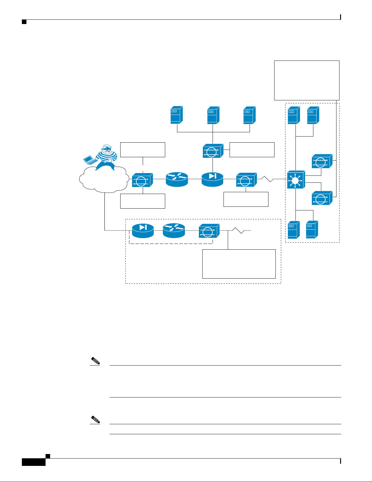
How the Sensor Functions
Sensor deployed
in IDS mode
Public services segment
Campus core
Attacker
Internet
Sensor deployed
in IPS mode
Sensor deployed
in IPS mode
Sensor deployed
in IPS mode
Sensor deployed in hybrid
mode to deliver IDS services
outside router and IPS
services inside the firewall
Service provider,
partner, or branch
office network
Multiple IPS sensors
deliver a highly scalable,
load-balanced solution
via Cisco Etherchannel
technology on Cisco
Catalyst Switches
148416
Main campus
Figure 1-1 Comprehensive Deployment Solutions
Chapter 1 Introducing the Sensor
The command and control interface is always Ethernet. This interface has an assigned IP address, which
allows it to communicate with the manager workstation or network devices (Cisco switches, routers, and
firewalls). Because this interface is visible on the network, you should use encryption to maintain data
privacy. SSH is used to protect the CLI and TLS/SSL is used to protect the manager workstation. SSH
and TLS/SSL are enabled by default on the manager workstations.
When responding to attacks, the sensor can do the following:
•
Insert TCP resets via the sensing interface.
Note
You should select the TCP reset action only on signatures associated with a TCP-based
service. If selected as an action on non-TCP-based services, no action is taken. Additionally,
TCP resets are not guaranteed to tear down an offending session because of limitations in
the TCP protocol.
•
Make ACL changes on switches, routers, and firewalls that the sensor manages.
Note
ACLs may block only future traffic, not current traffic.
1-2
Cisco Intrusion Prevention System Appliance and Module Installation Guide for IPS 7.1
OL-24002-01
Page 23

Chapter 1 Introducing the Sensor
•
Generate IP session logs, session replay, and trigger packets display.
IP session logs are used to gather information about unauthorized use. IP log files are written when
events occur that you have configured the appliance to look for.
•
Implement multiple packet drop actions to stop worms and viruses.
Your Network Topology
Before you deploy and configure your sensors, you should understand the following about your network:
•
The size and complexity of your network.
•
Connections between your network and other networks (and the Internet).
•
The amount and type of network traffic on your network.
This knowledge will help you determine how many sensors are required, the hardware configuration for
each sensor (for example, the size and type of network interface cards), and how many managers are
needed.
How the Sensor Functions
Correctly Deploying the Sensor
You should always position the IPS sensor behind a perimeter-filtering device, such as a firewall or
adaptive security appliance. The perimeter device filters traffic to match your security policy thus
allowing acceptable traffic in to your network. Correct placement significantly reduces the number of
alerts, which increases the amount of actionable data you can use to investigate security violations. If
you position the IPS sensor on the edge of your network in front of a firewall, your sensor will produce
alerts on every single scan and attempted attack even if they have no significance to your network
implementation. You will receive hundreds, thousands, or even millions of alerts (in a large enterprise
environment) that are not really critical or actionable in your environment. Analyzing this type of data
is time consuming and costly.
Tuning the IPS
Tuning the IPS ensures that the alerts you see reflect true actionable information. Without tuning the IPS,
it is difficult to do security research or forensics on your network because you will have thousands of
benign events, also known as false positives. False positives are a by-product of all IPS devices, but they
occur much less frequently in Cisco IPS devices since Cisco IPS devices are stateful, normalized, and
use vulnerability signatures for attack evaluation. Cisco IPS devices also provide risk rating, which
identifies high risk events, and policy-based management, which lets you deploy rules to enforce IPS
signature actions based on risk rating.
Follow these tips when tuning your IPS sensors:
•
Place your sensor on your network behind a perimeter-filtering device. Proper sensor placement can
reduce the number of alerts you need to examine by several thousands a day.
OL-24002-01
•
Deploy the sensor with the default signatures in place.
The default signature set provides you with a very high security protection posture. The Cisco
signature team has spent many hours on testing the defaults to give your sensor the highest
protection. If you think that you have lost these defaults, you can restore them.
•
Make sure that the event action override is set to drop packets with a risk rating greater than 90. This
is the default and ensures that high risk alerts are stopped immediately.
Cisco Intrusion Prevention System Appliance and Module Installation Guide for IPS 7.1
1-3
Page 24

How the Sensor Functions
Chapter 1 Introducing the Sensor
•
Filter out known false positives caused by specialized software, such as vulnerability scanner and
load balancers by one of the following methods:
–
You can configure the sensor to ignore the alerts from the IP addresses of the scanner and load
balancer.
–
You can configure the sensor to allow these alerts and then use the IME to filter out the false
positives.
•
Filter the Informational alerts.
These low priority events notifications could indicate that another device is doing reconnaissance
on a device protected by the IPS. Research the source IP addresses from these Informational alerts
to determine what the source is.
•
Analyze the remaining actionable alerts:
–
Research the alert.
–
Fix the attack source.
–
Fix the destination host.
–
Modify the IPS policy to provide more information.
For More Information
•
For a detailed description of risk rating, refer to Calculating the Risk Rating.
•
For information on Cisco signatures, for the IDM and IME refer to Defining Signatures, and for the
CLI refer to Defining Signatures.
•
For detailed information on event action overrides, for the IDM and IME refer to Configuring Event
Action Overrides, and for the CLI, refer to Configuring Event Action Overrides.
Sensor Interfaces
This section describes the sensor interfaces, and contains the following topics:
•
Understanding Sensor Interfaces, page 1-4
•
Command and Control Interface, page 1-5
•
Sensing Interfaces, page 1-6
•
Interface Support, page 1-6
•
TCP Reset Interfaces, page 1-11
•
Interface Restrictions, page 1-12
Understanding Sensor Interfaces
1-4
The sensor interfaces are named according to the maximum speed and physical location of the interface.
The physical location consists of a port number and a slot number. All interfaces that are built-in on the
sensor motherboard are in slot 0, and the interface card expansion slots are numbered beginning with
slot 1 for the bottom slot with the slot numbers increasing from bottom to top (except for the
IPS 4270-20, where the ports are numbered from top to bottom). Each physical interface can be divided
in to VLAN group subinterfaces, each of which consists of a group of VLANs on that interface.
Cisco Intrusion Prevention System Appliance and Module Installation Guide for IPS 7.1
OL-24002-01
Page 25

Chapter 1 Introducing the Sensor
There are three interface roles:
•
Command and control
•
Sensing
•
Alternate TCP reset
There are restrictions on which roles you can assign to specific interfaces and some interfaces have
multiple roles. You can configure any sensing interface to any other sensing interface as its TCP reset
interface. The TCP reset interface can also serve as an IDS (promiscuous) sensing interface at the same
time. The following restrictions apply:
•
The TCP reset interface that is assigned to a sensing interface has no effect in inline interface or
inline VLAN pair mode, because TCP resets are always sent on the sensing interfaces in those
modes.
•
There is only one sensing interface on the ASA IPS modules (ASA 5500 AIP SSM,
ASA 5500-X IPS SSP and ASA 5585-X IPS SSP), so you cannot designate an alternate TCP reset
interface.
•
On the IPS 4510 and IPS 4520, no interface-related configurations are allowed when the SensorApp
is down.
How the Sensor Functions
Command and Control Interface
The command and control interface has an IP address and is used for configuring the sensor. It receives
security and status events from the sensor and queries the sensor for statistics. The command and control
interface is permanently enabled. It is permanently mapped to a specific physical interface, which
depends on the specific model of sensor. You cannot use the command and control interface as either a
sensing or alternate TCP reset interface.
Table 1-1 lists the command and control interfaces for each sensor.
Table 1-1 Command and Control Interfaces
Sensor Command and Control Interface
ASA 5500 AIP SSM-10 GigabitEthernet 0/0
ASA 5500 AIP SSM-20 GigabitEthernet 0/0
ASA 5500 AIP SSM-40 GigabitEthernet 0/0
ASA 5512-X IPS SSP Management 0/0
ASA 5515-X IPS SSP Management 0/0
ASA 5525-X IPS SSP Management 0/0
ASA 5545-X IPS SSP Management 0/0
ASA 5555-X IPS SSP Management 0/0
ASA 5585-X IPS SSP-10 Management 0/0
ASA 5585-X IPS SSP-20 Management 0/0
ASA 5585-X IPS SSP-40 Management 0/0
ASA 5585-X IPS SSP-60 Management 0/0
IPS 4240 Management 0/0
IPS 4255 Management 0/0
OL-24002-01
Cisco Intrusion Prevention System Appliance and Module Installation Guide for IPS 7.1
1-5
Page 26

How the Sensor Functions
Sensing Interfaces
Chapter 1 Introducing the Sensor
Table 1-1 Command and Control Interfaces (continued)
Sensor Command and Control Interface
IPS 4260 Management 0/0
IPS 4270-20 Management 0/0
IPS 4345 Management 0/0
IPS 4360 Management 0/0
IPS 4510 Management 0/0
IPS 4520 Management 0/0
1. The 4500 series sensors have two management ports, Management 0/0 and
Management 0/1, but Management 0/1 is reserved for future use.
Sensing interfaces are used by the sensor to analyze traffic for security violations. A sensor has one or
more sensing interfaces depending on the sensor. Sensing interfaces can operate individually in
promiscuous mode or you can pair them to create inline interfaces.
1
1
Note
On appliances, all sensing interfaces are disabled by default. You must enable them to use them. On
modules, the sensing interfaces are permanently enabled.
Some appliances support optional interface cards that add sensing interfaces to the sensor. You must
insert or remove these optional cards while the sensor is powered off. The sensor detects the addition or
removal of a supported interface card. If you remove an optional interface card, some of the interface
configuration is deleted, such as the speed, duplex, description string, enabled/disabled state of the
interface, and any inline interface pairings. These settings are restored to their default settings when the
card is reinstalled. However, the assignment of promiscuous and inline interfaces to the Analysis Engine
is not deleted from the Analysis Engine configuration, but is ignored until those cards are reinserted and
you create the inline interface pairs again.
Interface Support
Table 1-2 describes the interface support for appliances and modules running Cisco IPS.
Table 1-2 Interface Support
Added
Interface
Base Chassis
Cards
ASA 5500 AIP SSM-10 — GigabitEthernet 0/1 by
ASA 5500 AIP SSM-20 — GigabitEthernet 0/1 by
Interfaces Supporting
Inline VLAN Pairs
(Sensing Ports)
security context instead of
VLAN pair or inline
interface pair
security context instead of
VLAN pair or inline
interface pair
Combinations Supporting
Inline Interface Pairs
GigabitEthernet 0/1 by
security context instead of
VLAN pair or inline
interface pair
GigabitEthernet 0/1 by
security context instead of
VLAN pair or inline
interface pair
Interfaces Not
Supporting Inline
(Command and Control
Port)
GigabitEthernet 0/0
GigabitEthernet 0/0
1-6
Cisco Intrusion Prevention System Appliance and Module Installation Guide for IPS 7.1
OL-24002-01
Page 27

Chapter 1 Introducing the Sensor
Table 1-2 Interface Support (continued)
Added
Interface
Base Chassis
Cards
ASA 5500 AIP SSM-40 — GigabitEthernet 0/1 by
ASA 5512-X IPS SSP — PortChannel 0/0 by security
ASA 5515-X IPS SSP — PortChannel 0/0 by security
ASA 5525-X IPS SSP — PortChannel 0/0 by security
ASA 5545-X IPS SSP — PortChannel 0/0 by security
ASA 5555-X IPS SSP — PortChannel 0/0 by security
ASA 5585-X IPS SSP-10 — PortChannel 0/0 by security
ASA 5585-X IPS SSP-20 — PortChannel 0/0 by security
ASA 5585-X IPS SSP-40 — PortChannel 0/0 by security
ASA 5585-X IPS SSP-60 — PortChannel 0/0 by security
IPS 4240 — GigabitEthernet 0/0
Interfaces Supporting
Inline VLAN Pairs
(Sensing Ports)
security context instead of
VLAN pair or inline
interface pair
context instead of VLAN
pair or inline interface pair
context instead of VLAN
pair or inline interface pair
context instead of VLAN
pair or inline interface pair
context instead of VLAN
pair or inline interface pair
context instead of VLAN
pair or inline interface pair
context instead of VLAN
pair or inline interface pair
context instead of VLAN
pair or inline interface pair
context instead of VLAN
pair or inline interface pair
context instead of VLAN
pair or inline interface pair
GigabitEthernet 0/1
GigabitEthernet 0/2
GigabitEthernet 0/3
Combinations Supporting
Inline Interface Pairs
GigabitEthernet 0/1 by
security context instead of
VLAN pair or inline
interface pair
PortChannel 0/0 by security
context instead of VLAN
pair or inline interface pair
PortChannel 0/0 by security
context instead of VLAN
pair or inline interface pair
PortChannel 0/0 by security
context instead of VLAN
pair or inline interface pair
PortChannel 0/0 by security
context instead of VLAN
pair or inline interface pair
PortChannel 0/0 by security
context instead of VLAN
pair or inline interface pair
PortChannel 0/0 by security
context instead of VLAN
pair or inline interface pair
PortChannel 0/0 by security
context instead of VLAN
pair or inline interface pair
PortChannel 0/0 by security
context instead of VLAN
pair or inline interface pair
PortChannel 0/0 by security
context instead of VLAN
pair or inline interface pair
0/0<->0/1
0/0<->0/2
0/0<->0/3
0/1<->0/2
0/1<->0/3
0/2<->0/3
How the Sensor Functions
Interfaces Not
Supporting Inline
(Command and Control
Port)
GigabitEthernet 0/0
Management 0/0
Management 0/0
Management 0/0
Management 0/0
Management 0/0
Management 0/0
Management 0/0
Management 0/0
Management 0/0
Management 0/0
OL-24002-01
Cisco Intrusion Prevention System Appliance and Module Installation Guide for IPS 7.1
1-7
Page 28

Chapter 1 Introducing the Sensor
How the Sensor Functions
Table 1-2 Interface Support (continued)
Interfaces Not
Added
Interface
Base Chassis
Cards
IPS 4255 — GigabitEthernet 0/0
Interfaces Supporting
Inline VLAN Pairs
(Sensing Ports)
GigabitEthernet 0/1
GigabitEthernet 0/2
GigabitEthernet 0/3
Combinations Supporting
Inline Interface Pairs
0/0<->0/1
0/0<->0/2
0/0<->0/3
0/1<->0/2
0/1<->0/3
0/2<->0/3
IPS 4260 — GigabitEthernet 0/1 N/A Management 0/0
IPS 4260 4GE-BP
GigabitEthernet 0/1
Supporting Inline
(Command and Control
Port)
Management 0/0
Management 0/0
Slot 1
GigabitEthernet 2/0
GigabitEthernet 2/1
2/0<->2/1
2/2<->2/3
1
GigabitEthernet 2/2
GigabitEthernet 2/3
Slot 2
GigabitEthernet 3/0
GigabitEthernet 3/1
3/0<->3/1
3/2<->3/3
GigabitEthernet 3/2
GigabitEthernet 3/3
IPS 4260 2SX
GigabitEthernet 0/1
All sensing ports can be
Management 0/0
paired together
Slot 1
GigabitEthernet 2/0
GigabitEthernet 2/1
Slot 2
GigabitEthernet 3/0
GigabitEthernet 3/1
IPS 4260 10GE
Slot 1
GigabitEthernet 0/1
TenGigabitEthernet 2/0
2/0<->2/1
Management 0/0
2
TenGigabitEthernet 2/1
IPS 4270-20 — — N/A Management 0/0
Management 0/1
IPS 4270-20 4GE-BP
Slot 1
GigabitEthernet 3/0
GigabitEthernet 3/1
3/0<->3/1
3/2<->3/3
4
Management 0/0
Management 0/1
GigabitEthernet 3/2
GigabitEthernet 3/3
3
4
1-8
Slot 2
GigabitEthernet 4/0
GigabitEthernet 4/1
4/0<->4/1
4/2<->4/3
GigabitEthernet 4/2
GigabitEthernet 4/3
Cisco Intrusion Prevention System Appliance and Module Installation Guide for IPS 7.1
OL-24002-01
Page 29

Chapter 1 Introducing the Sensor
Table 1-2 Interface Support (continued)
Base Chassis
Added
Interface
Cards
Interfaces Supporting
Inline VLAN Pairs
(Sensing Ports)
IPS 4270-20 2SX
Slot 1
GigabitEthernet 3/0
GigabitEthernet 3/1
Combinations Supporting
Inline Interface Pairs
All sensing ports can be
paired together
How the Sensor Functions
Interfaces Not
Supporting Inline
(Command and Control
Port)
Management 0/0
Management 0/1
4
Slot 2
GigabitEthernet 4/0
GigabitEthernet 4/1
IPS 4270-20 10GE
Slot 1
TenGigabitEthernet 5/0
TenGigabitEthernet 5/1
Slot 2
TenGigabitEthernet 7/0
TenGigabitEthernet 7/1
IPS 4345 — GigabitEthernet 0/0
GigabitEthernet 0/1
GigabitEthernet 0/2
GigabitEthernet 0/3
GigabitEthernet 0/4
GigabitEthernet 0/5
Gigabitethernet 0/6
GigabitEthernet 0/7
IPS 4360 — GigabitEthernet 0/0
GigabitEthernet 0/1
GigabitEthernet 0/2
All sensing ports can be
paired together
All sensing ports can be
paired together
All sensing ports can be
paired together
Management 0/0
Management 0/1
Management 0/0
Management 0/1
Management 0/0
Management 0/1
4
5
5
OL-24002-01
GigabitEthernet 0/3
GigabitEthernet 0/4
GigabitEthernet 0/5
GigabitEthernet 0/6
GigabitEthernet 0/7
Cisco Intrusion Prevention System Appliance and Module Installation Guide for IPS 7.1
1-9
Page 30

How the Sensor Functions
Table 1-2 Interface Support (continued)
Base Chassis
Added
Interface
Cards
Interfaces Supporting
Inline VLAN Pairs
(Sensing Ports)
IPS 4510 — GigabitEthernet 0/0
GigabitEthernet 0/1
GigabitEthernet 0/2
GigabitEthernet 0/3
GigabitEthernet 0/4
GigabitEthernet 0/5
TenGigabitEthernet 0/6
TenGigabitEthernet 0/7
TenGigabitEthernet 0/8
TenGigabitEthernet 0/9
IPS 4520 —TX GigabitEthernet 0/0
GigabitEthernet 0/1
Combinations Supporting
Inline Interface Pairs
All sensing ports can be
paired together
All sensing ports can be
paired together
Chapter 1 Introducing the Sensor
Interfaces Not
Supporting Inline
(Command and Control
Port)
Management 0/0
Management 0/1
6
Management 0/0
Management 0/1
6
GigabitEthernet 0/2
GigabitEthernet 0/3
GigabitEthernet 0/4
GigabitEthernet 0/5
TenGigabitEthernet 0/6
TenGigabitEthernet 0/7
TenGigabitEthernet 0/8
TenGigabitEthernet 0/9
1. To disable hardware bypass, pair the interfaces in any other combination (2/0<->2/2 and 2/1<->2/3, for example).
2. To disable hardware bypass, pair the interfaces in any other combination (2/0<->2/2 and 2/1<->2/3, for example).
3. Reserved for future use.
4. To disable hardware bypass, pair the interfaces in any other combination (2/0<->2/2 and 2/1<->2/3, for example).
5. Does not currently support hardware bypass.
6. Reserved for future use.
Note
The IPS 4260 supports a mixture of 4GE-BP, 2SX, and 10GE cards. The IPS 4270-20 supports a mixture
of 4GE-BP, 2SX, and 10GE cards up to a total of either six cards, or sixteen total ports, which ever is
reached first, but is limited to only two 10GE card in the mix of cards.
1-10
Cisco Intrusion Prevention System Appliance and Module Installation Guide for IPS 7.1
OL-24002-01
Page 31

Chapter 1 Introducing the Sensor
TCP Reset Interfaces
This section explains the TCP reset interfaces and when to use them. It contains the following topics:
•
Understanding Alternate TCP Reset Interfaces, page 1-11
•
Designating the Alternate TCP Reset Interface, page 1-12
Understanding Alternate TCP Reset Interfaces
How the Sensor Functions
Note
Note
The alternate TCP reset interface setting is ignored in inline interface or inline VLAN pair mode,
because resets are sent inline in these modes.
You can configure sensors to send TCP reset packets to try to reset a network connection between an
attacker host and its intended target host. In some installations when the interface is operating in
promiscuous mode, the sensor may not be able to send the TCP reset packets over the same sensing
interface on which the attack was detected. In such cases, you can associate the sensing interface with
an alternate TCP reset interface and any TCP resets that would otherwise be sent on the sensing interface
when it is operating in promiscuous mode are instead sent out on the associated alternate TCP reset
interface.
If a sensing interface is associated with an alternate TCP reset interface, that association applies when
the sensor is configured for promiscuous mode but is ignored when the sensing interface is configured
for inline mode. any sensing interface can serve as the alternate TCP reset interface for another sensing
interface.
There is only one sensing interface on the ASA IPS modules (ASA 5500 AIP SSM,
ASA 5500-X IPS SSP, and ASA 5585-X IPS SSP), so you cannot designate an alternate TCP reset
interface.
Table 1-3 lists the alternate TCP reset interfaces.
Table 1-3 Alternate TCP Reset Interfaces
OL-24002-01
Sensor Alternate TCP Reset Interface
ASA 5500 AIP SSM-10 None
ASA 5500 AIP SSM-20 None
ASA 5500 AIP SSM-40 None
ASA 5512-X IPS SSP None
ASA 5515-X IPS SSP None
ASA 5525-X IPS SSP None
ASA 5545-X IPS SSP None
ASA 5555-X IPS SSP None
ASA 5585-X IPS SSP-10 None
ASA 5585-X IPS SSP-20 None
ASA 5585-X IPS SSP-40 None
ASA 5585-X IPS SSP-60 None
Cisco Intrusion Prevention System Appliance and Module Installation Guide for IPS 7.1
1-11
Page 32

How the Sensor Functions
Table 1-3 Alternate TCP Reset Interfaces (continued)
Sensor Alternate TCP Reset Interface
IPS 4240 Any sensing interface
IPS 4255 Any sensing interface
IPS 4260 Any sensing interface
IPS 4270-20 Any sensing interface
IPS 4345 Any sensing interface
IPS 4360 Any sensing interface
IPS 4510 Any sensing interface
IPS 4520 Any sensing interface
Designating the Alternate TCP Reset Interface
Chapter 1 Introducing the Sensor
Note
There is only one sensing interface on the ASA IPS modules (ASA 5500 AIP SSM,
ASA 5500-X IPS SSP, and ASA 5585-X IPS SSP), so you cannot designate an alternate TCP reset
interface.
You need to designate an alternate TCP reset interface in the following situations:
•
•
•
Caution
You can only assign a sensing interface as an alternate TCP reset interface. You cannot configure the
management interface as an alternate TCP reset interface.
Interface Restrictions
The following restrictions apply to configuring interfaces on the sensor:
•
When a switch is being monitored with either SPAN or VACL capture and the switch does not accept
incoming packets on the SPAN or VACL capture port.
When a switch is being monitored with either SPAN or VACL capture for multiple VLANs, and the
switch does not accept incoming packets with 802.1q headers. The TCP resets need 802.1q headers
to tell which VLAN the resets should be sent on.
When a network tap is used for monitoring a connection. Taps do not permit incoming traffic from
the sensor.
Physical Interfaces
–
In IPS 7.1, rx/tx flow control is disabled on the IPS 4200 series sensors. This is a change from
IPS 7.0 where rx/tx flow control is enabled by default.
1-12
–
On the ASA IPS modules (ASA 5500 AIP SSM, ASA 5500-X IPS SSP, and
ASA 5585-X IPS SSP) all backplane interfaces have fixed speed, duplex, and state settings.
These settings are protected in the default configuration on all backplane interfaces.
–
For nonbackplane FastEthernet interfaces the valid speed settings are 10 Mbps, 100 Mbps, and
auto. Valid duplex settings are full, half, and auto.
Cisco Intrusion Prevention System Appliance and Module Installation Guide for IPS 7.1
OL-24002-01
Page 33

Chapter 1 Introducing the Sensor
–
–
–
•
Inline Interface Pairs
–
–
–
–
–
How the Sensor Functions
For Gigabit copper interfaces (1000-TX on the IPS 4240, IPS 4255, IPS 4260, IPS 4270-20,,
IPS 4345, IPS 4360, IPS 4510, and IPS 4520), valid speed settings are 10 Mbps, 100 Mbps,
1000 Mbps, and auto. Valid duplex settings are full, half, and auto.
For Gigabit (copper or fiber) interfaces, if the speed is configured for 1000 Mbps, the only valid
duplex setting is auto.
The command and control interface cannot also serve as a sensing interface.
Inline interface pairs can contain any combination of sensing interfaces regardless of the
physical interface type (copper versus fiber), speed, or duplex settings of the interface.
However, pairing interfaces of different media type, speeds, and duplex settings may not be
fully tested or supported.
The command and control interface cannot be a member of an inline interface pair.
You cannot pair a physical interface with itself in an inline interface pair.
A physical interface can be a member of only one inline interface pair.
You can only configure bypass mode and create inline interface pairs on sensor platforms that
support inline mode.
–
A physical interface cannot be a member of an inline interface pair unless the subinterface mode
of the physical interface is none.
Note
You can configure the ASA IPS modules (ASA 5500 AIP SSM, ASA 5500-X IPS SSP,
and ASA 5585-X IPS SSP) to operate inline even though they have only one sensing
interface.
•
Inline VLAN Pairs
–
You cannot pair a VLAN with itself.
–
You cannot use the default VLAN as one of the paired VLANs in an inline VLAN pair.
–
For a given sensing interface, a VLAN can be a member of only one inline VLAN pair.
However, a given VLAN can be a member of an inline VLAN pair on more than one sensing
interface.
–
The order in which you specify the VLANs in an inline VLAN pair is not significant.
–
A sensing interface in Inline VLAN Pair mode can have from 1 to 255 inline VLAN pairs.
Note
The ASA IPS modules (ASA 5500 AIP SSM ,ASA 5500-X IPS SSP, and
ASA 5585-X IPS SSP) do not support inline VLAN pairs.
•
Alternate TCP Reset Interface
–
You can only assign the alternate TCP reset interface to a sensing interface. You cannot
configure the command and control interface as an alternate TCP reset interface. The alternate
TCP reset interface option is set to none as the default and is protected for all interfaces except
the sensing interfaces.
OL-24002-01
–
You can assign the same physical interface as an alternate TCP reset interface for multiple
sensing interfaces.
–
A physical interface can serve as both a sensing interface and an alternate TCP reset interface.
Cisco Intrusion Prevention System Appliance and Module Installation Guide for IPS 7.1
1-13
Page 34

How the Sensor Functions
Chapter 1 Introducing the Sensor
–
The command and control interface cannot serve as the alternate TCP reset interface for a
sensing interface.
–
A sensing interface cannot serve as its own alternate TCP reset interface.
–
You can only configure interfaces that are capable of TCP resets as alternate TCP reset
interfaces.
Note
•
VLAN Groups
–
You can configure any single interface for promiscuous, inline interface pair, or inline VLAN
pair mode, but no combination of these modes is allowed.
–
You cannot add a VLAN to more than one group on each interface.
–
You cannot add a VLAN group to multiple virtual sensors.
–
An interface can have no more than 255 user-defined VLAN groups.
–
When you pair a physical interface, you cannot subdivide it; you can subdivide the pair.
–
You can use a VLAN on multiple interfaces; however, you receive a warning for this
configuration.
–
You can assign a virtual sensor to any combination of one or more physical interfaces and inline
VLAN pairs, subdivided or not.
–
You can subdivide both physical and logical interfaces into VLAN groups.
–
The CLI, IDM, and IME prompt you to remove any dangling references. You can leave the
dangling references and continue editing the configuration.
–
The CLI, IDM, and IME do not allow configuration changes in Analysis Engine that conflict
with the interface configuration.
There is only one sensing interface on the ASA IPS modules (ASA 5500 AIP SSM,
ASA 5500-X IPS SSP, and ASA 5585-X IPS SSP), so you cannot designate an
alternate TCP reset interface.
Interface Modes
The following section describes the interface modes, and contains the following topics:
•
•
•
•
Cisco Intrusion Prevention System Appliance and Module Installation Guide for IPS 7.1
1-14
–
The CLI allows configuration changes in the interface configuration that cause conflicts in the
Analysis Engine configuration. The IDM and IME do not allow changes in the interface
configuration that cause conflicts in the Analysis Engine configuration.
Note
The ASA IPS modules (ASA 5500 AIP SSM, ASA 5500-X IPS SSP, and
ASA 5585-X IPS SSP) do not support VLAN groups mode.
Promiscuous Mode, page 1-15
IPv6, Switches, and Lack of VACL Capture, page 1-15
Inline Interface Pair Mode, page 1-16
Inline VLAN Pair Mode, page 1-17
OL-24002-01
Page 35

Chapter 1 Introducing the Sensor
Router
Host
Sensor
Switch
Span port sending
copies of VLAN A traffic
253443
VLAN A
•
•
Promiscuous Mode
In promiscuous mode, packets do not flow through the sensor. The sensor analyzes a copy of the
monitored traffic rather than the actual forwarded packet. The advantage of operating in promiscuous
mode is that the sensor does not affect the packet flow with the forwarded traffic. The disadvantage of
operating in promiscuous mode, however, is the sensor cannot stop malicious traffic from reaching its
intended target for certain types of attacks, such as atomic attacks (single-packet attacks). The response
actions implemented by promiscuous sensor devices are post-event responses and often require
assistance from other networking devices, for example, routers and firewalls, to respond to an attack.
While such response actions can prevent some classes of attacks, in atomic attacks the single packet has
the chance of reaching the target system before the promiscuous-based sensor can apply an ACL
modification on a managed device (such as a firewall, switch, or router).
By default, all sensing interfaces are in promiscuous mode. To change an interface from inline interface
mode to promiscuous mode, delete any inline interface that contains that interface and delete any inline
VLAN pair subinterfaces of that interface from the interface configuration.
How the Sensor Functions
VLAN Group Mode, page 1-18
Deploying VLAN Groups, page 1-18
Figure 1-2 illustrates promiscuous mode:
Figure 1-2 Promiscuous Mode
IPv6, Switches, and Lack of VACL Capture
VACLs on Catalyst switches do not have IPv6 support. The most common method for copying traffic to
a sensor configured in promiscuous mode is to use VACL capture. If you want to have IPv6 support, you
can use SPAN ports.
However, you can only configure up to two monitor sessions on a switch unless you use the following
configuration:
OL-24002-01
•
Monitor session
•
Multiple trunks to one or more sensors
•
Restrict per trunk port which VLANs are allowed to perform monitoring of many VLANs to more
than two different sensors or virtual sensors within one IPS
Cisco Intrusion Prevention System Appliance and Module Installation Guide for IPS 7.1
1-15
Page 36

How the Sensor Functions
The following configuration uses one SPAN session to send all of the traffic on any of the specified
VLANs to all of the specified ports. Each port configuration only allows a particular VLAN or VLANs
to pass. Thus you can send data from different VLANs to different sensors or virtual sensors all with one
SPAN configuration line:
clear trunk 4/1-4 1-4094
set trunk 4/1 on dot1q 930
set trunk 4/2 on dot1q 932
set trunk 4/3 on dot1q 960
set trunk 4/4 on dot1q 962
set span 930, 932, 960, 962 4/1-4 both
Chapter 1 Introducing the Sensor
Note
The SPAN/Monitor configuration is valuable when you want to assign different IPS policies per VLAN
or when you have more bandwidth to monitor than one interface can handle.
For More Information
For more information on promiscuous mode, see Promiscuous Mode, page 1-15.
Inline Interface Pair Mode
Operating in inline interface pair mode puts the IPS directly into the traffic flow and affects
packet-forwarding rates making them slower by adding latency. This allows the sensor to stop attacks by
dropping malicious traffic before it reaches the intended target, thus providing a protective service. Not
only is the inline device processing information on Layers 3 and 4, but it is also analyzing the contents
and payload of the packets for more sophisticated embedded attacks (Layers 3 to 7). This deeper analysis
lets the system identify and stop and/or block attacks that would normally pass through a traditional
firewall device.
In inline interface pair mode, a packet comes in through the first interface of the pair on the sensor and
out the second interface of the pair. The packet is sent to the second interface of the pair unless that
packet is being denied or modified by a signature.
Note
You can configure the ASA IPS modules (ASA 5500 AIP SSM, ASA 5500-X IPS SSP, and
ASA 5585-X IPS SSP) to operate inline even though they have only one sensing interface.
1-16
Note
If the paired interfaces are connected to the same switch, you should configure them on the switch as
access ports with different access VLANs for the two ports. Otherwise, traffic does not flow through the
inline interface.
Cisco Intrusion Prevention System Appliance and Module Installation Guide for IPS 7.1
OL-24002-01
Page 37

Chapter 1 Introducing the Sensor
Host
Sensor
Switch
Traffic passes
through interface pair
253444
Router
VLAN A
Host
Sensor
Switch
253445
Router
VLAN B
VLAN A
Pairing VLAN A and B
Trunk port carrying
VLAN A and B
Figure 1-3 illustrates inline interface pair mode:
Figure 1-3 Inline Interface Pair Mode
Inline VLAN Pair Mode
How the Sensor Functions
Note
Note
The ASA IPS modules (,ASA 5500 AIP SSM, ASA 5500-X IPS SSP, and ASA 5585-X IPS SSP) do not
support inline VLAN pairs.
You can associate VLANs in pairs on a physical interface. This is known as inline VLAN pair mode.
Packets received on one of the paired VLANs are analyzed and then forwarded to the other VLAN in the
pair.
Inline VLAN pair mode is an active sensing mode where a sensing interface acts as an 802.1q trunk port,
and the sensor performs VLAN bridging between pairs of VLANs on the trunk. The sensor inspects the
traffic it receives on each VLAN in each pair, and can either forward the packets on the other VLAN in
the pair, or drop the packet if an intrusion attempt is detected. You can configure an IPS sensor to
simultaneously bridge up to 255 VLAN pairs on each sensing interface. The sensor replaces the
VLAN ID field in the 802.1q header of each received packet with the ID of the egress VLAN on which
the sensor forwards the packet. The sensor drops all packets received on any VLANs that are not
assigned to inline VLAN pairs.
You cannot use the default VLAN as one of the paired VLANs in an inline VLAN pair.
Figure 1-4 illustrates inline VLAN pair mode:
Figure 1-4 Inline VLAN Pair Mode
OL-24002-01
Cisco Intrusion Prevention System Appliance and Module Installation Guide for IPS 7.1
1-17
Page 38

How the Sensor Functions
VLAN Group Mode
Chapter 1 Introducing the Sensor
Note
Note
The ASA IPS modules (ASA 5500 AIP SSM, ASA 5500-X IPS SSP, and ASA 5585-X IPS SSP) do not
support VLAN groups mode.
You can divide each physical interface or inline interface into VLAN group subinterfaces, each of which
consists of a group of VLANs on that interface. Analysis Engine supports multiple virtual sensors, each
of which can monitor one or more of these interfaces. This lets you apply multiple policies to the same
sensor. The advantage is that now you can use a sensor with only a few interfaces as if it had many
interfaces.
You cannot divide physical interfaces that are in inline VLAN pairs into VLAN groups.
VLAN group subinterfaces associate a set of VLANs with a physical or inline interface. No VLAN can
be a member of more than one VLAN group subinterface. Each VLAN group subinterface is identified
by a number between 1 and 255. Subinterface 0 is a reserved subinterface number used to represent the
entire unvirtualized physical or logical interface. You cannot create, delete, or modify subinterface 0 and
no statistics are reported for it.
An unassigned VLAN group is maintained that contains all VLANs that are not specifically assigned to
another VLAN group. You cannot directly specify the VLANs that are in the unassigned group. When a
VLAN is added to or deleted from another VLAN group subinterface, the unassigned group is updated.
Packets in the native VLAN of an 802.1q trunk do not normally have 802.1q encapsulation headers to
identify the VLAN number to which the packets belong. A default VLAN variable is associated with
each physical interface and you should set this variable to the VLAN number of the native VLAN or to 0.
The value 0 indicates that the native VLAN is either unknown or you do not care if it is specified. If the
default VLAN setting is 0, the following occurs:
•
Any alerts triggered by packets without 802.1q encapsulation have a VLAN value of 0 reported in
the alert.
•
Non-802.1q encapsulated traffic is associated with the unassigned VLAN group and it is not
possible to assign the native VLAN to any other VLAN group.
Note
You can configure a port on a switch as either an access port or a trunk port. On an access port, all traffic
is in a single VLAN is called the access VLAN. On a trunk port, multiple VLANs can be carried over
the port, and each packet has a special header attached called the 802.1q header that contains the VLAN
ID. This header is commonly referred as the VLAN tag. However, a trunk port has a special VLAN called
the native VLAN. Packets in the native VLAN do not have the 802.1q headers attached.
Deploying VLAN Groups
Because a VLAN group of an inline pair does not translate the VLAN ID, an inline paired interface must
exist between two switches to use VLAN groups on a logical interface. For an appliance, you can connect
the two pairs to the same switch, make them access ports, and then set the access VLANs for the two
ports differently. In this configuration, the sensor connects between two VLANs, because each of the
two ports is in access mode and carries only one VLAN. In this case the two ports must be in different
VLANs, and the sensor bridges the two VLANs, monitoring any traffic that flows between the two
VLANs.
1-18
Cisco Intrusion Prevention System Appliance and Module Installation Guide for IPS 7.1
OL-24002-01
Page 39

Chapter 1 Introducing the Sensor
You can also connect appliances between two switches. There are two variations. In the first variation,
the two ports are configured as access ports, so they carry a single VLAN. In this way, the sensor bridges
a single VLAN between the two switches.
In the second variation, the two ports are configured as trunk ports, so they can carry multiple VLANs.
In this configuration, the sensor bridges multiple VLANs between the two switches. Because multiple
VLANs are carried over the inline interface pair, the VLANs can be divided into groups and each group
can be assigned to a virtual sensor.
Supported Sensors
Supported Sensors
Caution
Installing the most recent software on unsupported sensors may yield unpredictable results. We do not
support software installed on unsupported platforms.
The currently supported IPS 7.1(x) versions are 7.1(1)E4, 7.1(2)E4, 7.1(3)E4, 7.1(4)E4, 7.1(5)E4, and
IPS 7.1(6)E4. All IPS sensors are not supported in each 7.1(x) version.
For a list of the specific IPS filenames and the IPS versions that each sensor supports, refer to the Release
Notes for your IPS version found at this URL:
http://www.cisco.com/en/US/products/hw/vpndevc/ps4077/prod_release_notes_list.html
Table 1-4 lists the sensors (IPS appliances and modules) that are supported by Cisco IPS.
Table 1-4 Supported Sensors
Model Name Part Number Optional Interfaces
Appliances
IPS 4240 IPS-4240-K9
IPS-4240-DC-K9
IPS 4255 IPS-4255-K9 —
IPS 4260 IPS-4260-K9
IPS-4260-4GE-BP-K9
IPS-4260-2SX-K9
IPS-4260-2X10GE-SR-K9
IPS 4270-20 IPS-4270-K9
1
—
—
IPS-4GE-BP-INT=
IPS-2SX-INT=
IPS-2X10GE-SR-INT=
—
—
—
IPS-4GE-BP-INT=
IPS-2SX-INT=
IPS-2X10GE-SR-INT=
OL-24002-01
IPS-4270-4GE-BP-K9
IPS-4270-2SX-K9
IPS-4270-2X10GE-SR-K9
IPS 4345 IPS-4345-K9 —
IPS 4360 IPS-4360-K9 —
IPS 4510 IPS 4510-K9 —
Cisco Intrusion Prevention System Appliance and Module Installation Guide for IPS 7.1
—
—
—
1-19
Page 40

IPS Appliances
Chapter 1 Introducing the Sensor
Table 1-4 Supported Sensors (continued)
Model Name Part Number Optional Interfaces
Appliances
IPS 4520 IPS 4520-K9 —
Modules
ASA 5500 AIP SSM-10 ASA-SSM-AIP-10-K9 —
ASA 5500 AIP SSM-20 ASA-SSM-AIP-20-K9 —
ASA 5500 AIP SSM-40 ASA-SSM-AIP-40-K9 —
ASA 5512-X ASA5512-K7
ASA5512-K8
ASA5512-DC-K8
ASA 5515-X ASA5515-K7
ASA5515-K8
ASA5515-DC
ASA5515-DC-K8
ASA 5525-X ASA5525-K7
ASA5525-K8
ASA5525-K9
ASA5525-DC
ASA 5545-X ASA5545-K7
ASA5545-K8
ASA5545-K9
ASA5545-DC-K8
ASA5545-CU-2AC-K9
ASA 5555-X ASA5555-K8
ASA5555-CU-2AC-K9
ASA 5585-X IPS SSP-10 ASA-SSP-IPS10-K9 —
ASA 5585-X IPS SSP-20 ASA-SSP-IPS20-K9 —
ASA 5585-X IPS SSP-40 ASA-SSP-IPS40-K9 —
ASA 5585-X IPS SSP-60 ASA-SSP-IPS60-K9 —
1. IPS-4240-DC-K9 is a NEBS-compliant product.
ASA-IC-6GE-CU-A=
ASA-IC-6GE-SFP-A=
ASA-IC-6GE-CU-A=
ASA-IC-6GE-SFP-A=
ASA-IC-6GE-CU-B=
ASA-IC-6GE-SFP-B=
ASA-IC-6GE-CU-C=
ASA-IC-6GE-SFP-C=
ASA-IC-6GE-CU-C=
ASA-IC-6GE-SFP-C=
For More Information
For instructions on how to obtain the most recent Cisco IPS software, see Obtaining Cisco IPS Software,
page C-1.
IPS Appliances
This section describes the Cisco appliance, and contains the following topics:
•
Introducing the IPS Appliance, page 1-21
•
Appliance Restrictions, page 1-22
•
Connecting an Appliance to a Terminal Server, page 1-22
Cisco Intrusion Prevention System Appliance and Module Installation Guide for IPS 7.1
1-20
OL-24002-01
Page 41

Chapter 1 Introducing the Sensor
Introducing the IPS Appliance
IPS Appliances
Note
The currently supported Cisco IPS appliances are the IPS 4240, IPS 4255, and IPS 4260 [IPS 7.0(x) and
later and IPS 7.1(5) and later], IPS 4270-20 [IPS 7.1(3) and later], IPS 4345 and IPS 4360 [IPS 7.1(3)
and later], and IPS 4510 and IPS 4520 [IPS 7.1(4) and later].
The IPS appliance is a high-performance, plug-and-play device. The appliance is a component of the
IPS, a network-based, real-time intrusion prevention system. You can use the IPS CLI, IDM, IME,
ASDM, or CSM to configure the appliance. For a list of IPS documents and how to access them, refer
to Documentation Roadmap for Cisco Intrusion Prevention System 7.1.
You can configure the appliance to respond to recognized signatures as it captures and analyzes network
traffic. These responses include logging the event, forwarding the event to the manager, performing a
TCP reset, generating an IP log, capturing the alert trigger packet, and reconfiguring a router. The
appliance offers significant protection to your network by helping to detect, classify, and stop threats
including worms, spyware and adware, network viruses, and application abuse.
After being installed at key points in the network, the appliance monitors and performs real-time analysis
of network traffic by looking for anomalies and misuse based on an extensive, embedded signature
library. When the system detects unauthorized activity, appliances can terminate the specific connection,
permanently block the attacking host, log the incident, and send an alert to the manager. Other legitimate
connections continue to operate independently without interruption.
Appliances are optimized for specific data rates and are packaged in Ethernet, Fast Ethernet, and Gigabit
Ethernet configurations. In switched environments, appliances must be connected to the SPAN port or
VACL capture port of the switch.
The Cisco IPS appliances provide the following:
•
Protection of multiple network subnets through the use of up to eight interfaces
•
Simultaneous, dual operation in both promiscuous and inline modes
•
A wide array of performance options—from 80 Mbps to multiple gigabits
•
Embedded web-based management solutions packaged with the sensor
For More Information
•
For a list of supported appliances, see Supported Sensors, page 1-19.
•
For a description of the IPS 4240 and IPS 4255, see Chapter 3, “Installing the IPS 4240 and IPS
4255.”
•
For a description of the IPS 4270-20, see Chapter 5, “Installing the IPS 4270-20.”
•
For a description of the IPS 4345 and IPS 4360, see Chapter 6, “Installing the IPS 4345 and
IPS 4360.”
•
For a description of the IPS 4510 and IPS 4520, see Chapter 7, “Installing the IPS 4510 and
IPS 4520.”
•
For a description of the ASA 5500 AIP SSM, see Chapter 8, “Installing and Removing the ASA
5500 AIP SSM.”
•
For a description of the ASA 5585-X IPS SSP, see Chapter 9, “Installing and Removing the
ASA 5585-X IPS SSP.”
OL-24002-01
Cisco Intrusion Prevention System Appliance and Module Installation Guide for IPS 7.1
1-21
Page 42

IPS Appliances
Appliance Restrictions
The following restrictions apply to using and operating the appliance:
•
The appliance is not a general purpose workstation.
•
Cisco Systems prohibits using the appliance for anything other than operating Cisco IPS.
•
Cisco Systems prohibits modifying or installing any hardware or software in the appliance that is
not part of the normal operation of the Cisco IPS.
Connecting an Appliance to a Terminal Server
A terminal server is a router with multiple, low speed, asynchronous ports that are connected to other
serial devices. You can use terminal servers to remotely manage network equipment, including
appliances. To set up a Cisco terminal server with RJ-45 or hydra cable assembly connections, follow
these steps:
Chapter 1 Introducing the Sensor
Step 1
Step 2
Step 3
Caution
Connect to a terminal server using one of the following methods:
•
For terminal servers with RJ-45 connections, connect a rollover cable from the console port on the
appliance to a port on the terminal server.
•
For hydra cable assemblies, connect a straight-through patch cable from the console port on the
appliance to a port on the terminal server.
Configure the line and port on the terminal server. In enable mode, enter the following configuration,
where # is the line number of the port to be configured.
config t
line #
login
transport input all
stopbits 1
flowcontrol hardware
speed 9600
exit
exit
wr mem
Be sure to properly close a terminal session to avoid unauthorized access to the appliance. If a terminal
session is not stopped properly, that is, if it does not receive an exit(0) signal from the application that
initiated the session, the terminal session can remain open. When terminal sessions are not stopped
properly, authentication is not performed on the next session that is opened on the serial port.
Always exit your session and return to a login prompt before terminating the application used to establish
the connection.
1-22
Caution
If a connection is dropped or terminated by accident, you should reestablish the connection and exit
normally to prevent unauthorized access to the appliance.
Cisco Intrusion Prevention System Appliance and Module Installation Guide for IPS 7.1
OL-24002-01
Page 43

Chapter 1 Introducing the Sensor
Time Sources and the Sensor
This section explains the importance of having a reliable time source for the sensors and how to correct
the time if there is an error. It contains the following topics:
•
The Sensor and Time Sources, page 1-23
•
Synchronizing IPS Module System Clocks with the Parent Device System Clock, page 1-23
•
Verifying the Sensor is Synchronized with the NTP Server, page 1-24
•
Correcting the Time on the Sensor, page 1-24
The Sensor and Time Sources
Time Sources and the Sensor
Note
We recommend that you use an NTP server to regulate time on your sensor. You can use authenticated
or unauthenticated NTP. For authenticated NTP, you must obtain the NTP server IP address, NTP server
key ID, and the key value from the NTP server. You can set up NTP during initialization or you can
configure NTP through the CLI, IDM, IME, or ASDM.
The sensor requires a reliable time source. All events (alerts) must have the correct UTC and local time
stamp, otherwise, you cannot correctly analyze the logs after an attack. When you initialize the sensor,
you set up the time zones and summertime settings. This section provides a summary of the various ways
to set the time on sensors.
The IPS Standalone Appliances
•
Use the clock set command to set the time. This is the default.
•
Configure the appliance to get its time from an NTP time synchronization source.
Note
The ASA IPS Modules
•
The ASA 5500-X IPS SSP and ASA 5585-X IPS SSP automatically synchronize their clocks with
the clock in the adaptive security appliance in which they are installed. This is the default.
•
Configure them to get their time from an NTP time synchronization source, such as a Cisco router
other than the parent router.
The currently supported Cisco IPS appliances are the IPS 4240, IPS 4255, and IPS 4260 [IPS
7.0(x) and later and IPS 7.1(5) and later], IPS 4270-20 [IPS 7.1(3) and later], IPS 4345 and
IPS 4360 [IPS 7.1(3) and later], and IPS 4510 and IPS 4520 [IPS 7.1(4) and later].
Synchronizing IPS Module System Clocks with the Parent Device System Clock
The ASA IPS modules (ASA 5500 AIP SSM, ASA 5500-X IPS SSP, and ASA 5585-X IPS SSP)
synchronize their clocks to the parent chassis clock (switch, router, or adaptive security appliance) each
time the IPS boots up and any time the parent chassis clock is set. The IPS clock and parent chassis clock
tend to drift apart over time. The difference can be as much as several seconds per day. To avoid this
problem, make sure that both the IPS clock and the parent clock are synchronized to an external NTP
server. If only the IPS clock or only the parent chassis clock is synchronized to an NTP server, the time
drift occurs.
Cisco Intrusion Prevention System Appliance and Module Installation Guide for IPS 7.1
OL-24002-01
1-23
Page 44

Time Sources and the Sensor
Verifying the Sensor is Synchronized with the NTP Server
In the Cisco IPS, you cannot apply an incorrect NTP configuration, such as an invalid NTP key value or
ID, to the sensor. If you try to apply an incorrect configuration, you receive an error message. To verify
the NTP configuration, use the show statistics host command to gather sensor statistics. The NTP
statistics section provides NTP statistics including feedback on sensor synchronization with the NTP
server.
To verify the NTP configuration, follow these steps:
Chapter 1 Introducing the Sensor
Step 1
Step 2
Step 3
Step 4
Log in to the sensor.
Generate the host statistics.
sensor# show statistics host
...
NTP Statistics
remote refid st t when poll reach delay offset jitter
11.22.33.44 CHU_AUDIO(1) 8 u 36 64 1 0.536 0.069 0.001
LOCAL(0) 73.78.73.84 5 l 35 64 1 0.000 0.000 0.001
ind assID status conf reach auth condition last_event cnt
1 10372 f014 yes yes ok reject reachable 1
2 10373 9014 yes yes none reject reachable 1
status = Not Synchronized
...
Generate the hosts statistics again after a few minutes.
sensor# show statistics host
...
NTP Statistics
remote refid st t when poll reach delay offset jitter
*11.22.33.44 CHU_AUDIO(1) 8 u 22 64 377 0.518 37.975 33.465
LOCAL(0) 73.78.73.84 5 l 22 64 377 0.000 0.000 0.001
ind assID status conf reach auth condition last_event cnt
1 10372 f624 yes yes ok sys.peer reachable 2
2 10373 9024 yes yes none reject reachable 2
status = Synchronized
If the status continues to read
Not Synchronized
, check with the NTP server administrator to make sure
the NTP server is configured correctly.
Correcting the Time on the Sensor
If you set the time incorrectly, your stored events will have the incorrect time because they are stamped
with the time the event was created. The Event Store time stamp is always based on UTC time. If during
the original sensor setup, you set the time incorrectly by specifying 8:00 p.m. rather than 8:00 a.m.,
when you do correct the error, the corrected time will be set backwards. New events might have times
older than old events.
For example, if during the initial setup, you configure the sensor as central time with daylight saving
time enabled and the local time is 8:04 p.m., the time is displayed as 20:04:37 CDT and has an offset
from UTC of -5 hours (01:04:37 UTC, the next day). A week later at 9:00 a.m., you discover the error:
the clock shows 21:00:23 CDT. You then change the time to 9:00 a.m. and now the clock shows
09:01:33 CDT. Because the offset from UTC has not changed, it requires that the UTC time now be
14:01:33 UTC, which creates the time stamp problem.
Cisco Intrusion Prevention System Appliance and Module Installation Guide for IPS 7.1
1-24
OL-24002-01
Page 45

Chapter 1 Introducing the Sensor
To ensure the integrity of the time stamp on the event records, you must clear the event archive of the
older events by using the clear events command.
Time Sources and the Sensor
Note
You cannot remove individual events.
For More Information
For the procedure for clearing events, refer to Clearing Events from Event Store.
OL-24002-01
Cisco Intrusion Prevention System Appliance and Module Installation Guide for IPS 7.1
1-25
Page 46

Time Sources and the Sensor
Chapter 1 Introducing the Sensor
1-26
Cisco Intrusion Prevention System Appliance and Module Installation Guide for IPS 7.1
OL-24002-01
Page 47

Preparing the Appliance for Installation
This chapter describes the steps to follow before installing new hardware or performing hardware
upgrades, and includes the following sections:
•
Installation Preparation, page 2-1
•
Safety Recommendations, page 2-2
•
General Site Requirements, page 2-5
Installation Preparation
To prepare for installing an appliance, follow these steps:
Step 1
Review the safety precautions outlined in one of the following safety documents:
•
Regulatory Compliance and Safety Information for the Cisco Intrusion Prevention System 4200
Series Appliance Sensor
CHA PTER
2
Step 2
Step 3
Step 4
Step 5
Step 6
Step 7
•
Regulatory Compliance and Safety Information for the Cisco ASA 5500-X Series Adaptive Security
Appliances and the Intrusion Prevention System 4300 Series Appliances
•
Regulatory Compliance and Safety Information for the Cisco Intrusion Prevention System 4500
Series Sensor Appliance.
To familiarize yourself with the IPS and related documentation and where to find it on Cisco.com, read
the Documentation Roadmap for Cisco Intrusion Prevention System 7.1.
Before proceeding with appliance installation, read the Release Notes for your software version, found
at this URL:
http://www.cisco.com/en/US/products/hw/vpndevc/ps4077/prod_release_notes_list.html
Unpack the appliance. An accessory kit ships with the appliance. Refer to the chapter for your appliance
for the accessory kit contents.
Place the appliance in an ESD-controlled environment.
Place the appliance on a stable work surface.
For installation instructions, see the chapter on your sensor in this book, Cisco Intrusion Prevention
System Appliance and Module Installation Guide for IPS 7.1.
OL-24002-01
Cisco Intrusion Prevention System Appliance and Module Installation Guide for IPS 7.1
2-1
Page 48

Safety Recommendations
For More Information
•
For ESD guidelines, see Electricity Safety Guidelines, page 2-2.
•
For the procedure for working in an ESD environment, see Working in an ESD Environment,
page 2-4.
Safety Recommendations
This section lists the safety precautions you should take when working with IPS appliances, and contains
the following topics:
•
Safety Guidelines, page 2-2
•
Electricity Safety Guidelines, page 2-2
•
Preventing Electrostatic Discharge Damage, page 2-3
•
Working in an ESD Environment, page 2-4
Safety Guidelines
Chapter 2 Preparing the Appliance for Installation
Use the following guidelines to help ensure your safety and protect the appliance. The list of guidelines
may not address all potentially hazardous situations in your working environment, so be alert and
exercise good judgement at all times.
Note
Removing the chassis cover to install a hardware component does not affect your Cisco warranty.
Upgrading the appliance does not require any special tools and does not create any radio frequency leaks.
The safety guidelines are as follows:
•
Keep the chassis area clear and dust-free before, during and after installation.
•
Keep tools away from walk areas where you and others could fall over them.
•
Do not wear loose clothing or jewelry, such as earrings, bracelets, or chains, that could get caught
in the chassis.
•
Wear safety glasses if you are working under any conditions that might be hazardous to your eyes.
•
Do not perform any action that creates a potential hazard to people or makes the equipment unsafe.
•
Never attempt to lift an object that is too heavy for one person to handle.
Electricity Safety Guidelines
2-2
Warning
Cisco Intrusion Prevention System Appliance and Module Installation Guide for IPS 7.1
Before working on a chassis or working near power supplies, unplug the power cord on AC units;
disconnect the power at the circuit breaker on DC units.
Statement 12
OL-24002-01
Page 49

Chapter 2 Preparing the Appliance for Installation
Follow these guidelines when working on equipment powered by electricity:
•
Before beginning procedures that require access to the interior of the chassis, locate the emergency
power-off switch for the room in which you are working. Then, if an electrical accident occurs, you
can act quickly to turn off the power.
•
Do not work alone if potentially hazardous conditions exist anywhere in your work space.
•
Never assume that power is disconnected from a circuit; always check the circuit.
•
Look carefully for possible hazards in your work area, such as moist floors, ungrounded power
extension cables, frayed power cords, and missing safety grounds.
•
If an electrical accident occurs, proceed as follows:
–
Use caution; do not become a victim yourself.
–
Disconnect power from the system.
–
If possible, send another person to get medical aid. Otherwise, assess the condition of the victim
and then call for help.
–
Determine if the person needs rescue breathing or external cardiac compressions; then take
appropriate action.
•
Use the chassis within its marked electrical ratings and product usage instructions.
Safety Recommendations
•
Install the appliance in compliance with local and national electrical codes as listed in one of the
following safety documents:
–
Regulatory Compliance and Safety Information for the Cisco Intrusion Prevention System 4200
Series Appliance Sensor
–
Regulatory Compliance and Safety Information for the Cisco ASA 5500-X Series Adaptive
Security Appliances and the Intrusion Prevention System 4300 Series Appliances
–
Regulatory Compliance and Safety Information for the Cisco Intrusion Prevention System 4500
Series Sensor Appliance.
•
The sensor models equipped with AC-input power supplies are shipped with a 3-wire electrical cord
with a grounding-type plug that fits only a grounding-type power outlet. This is a safety feature that
you should not circumvent. Equipment grounding should comply with local and national electrical
codes.
Preventing Electrostatic Discharge Damage
Electrostatic discharge (ESD) can damage equipment and impair electrical circuitry. ESD damage occurs
when electronic components are improperly handled, which can result in complete or intermittent
failures.
•
Always follow ESD-prevention procedures when you remove and replace components. Make sure
that the chassis is electrically connected to earth ground. Wear an ESD-preventive wrist strap, and
make sure that it makes good skin contact. Connect the grounding clip to an unpainted surface of
the chassis frame to safely ground unwanted ESD voltage. To guard against ESD damage and
shocks, the wrist strap and cord must operate properly. If no wrist strap is available, ground yourself
by touching the metal part of the chassis.
OL-24002-01
•
For safety, periodically check the resistance value of the antistatic strap, which should be between
1 and 10 megohms (Mohms).
Cisco Intrusion Prevention System Appliance and Module Installation Guide for IPS 7.1
2-3
Page 50

Safety Recommendations
D
O
N
O
T
I
N
S
T
A
L
L
I
N
T
E
R
F
A
C
E
C
A
R
D
S
W
I
T
H
P
O
W
E
R
A
P
P
L
I
E
D
C
O
N
S
O
L
E
1
0
/1
0
0
E
T
H
E
R
N
E
T
0
/
0
Lin
k
F
D
X
FD
X
10
0 M
bp
s
Lin
k
100
M
bps
F
A
ILO
V
ER
1
0
/
1
0
0
E
T
H
E
R
N
E
T
0
/
0
PIX-515
148409
Copper foil
Working in an ESD Environment
Work on ESD-sensitive parts only at an approved static-safe station on a grounded static dissipative work
surface, for example, an ESD workbench or static dissipative mat.
To remove and replace components in a sensor, follow these steps:
Chapter 2 Preparing the Appliance for Installation
Step 1
Step 2
Step 3
Remove all static-generating items from your work area.
Use a static dissipative work surface and wrist strap.
Note
Disposable wrist straps, typically those included with an upgrade part, are designed for one time
use.
Attach the wrist strap to your wrist and to the terminal on the work surface. If you are using a disposable
wrist strap, connect the wrist strap directly to an unpainted metal surface of the chassis.
2-4
Step 4
Caution
Connect the work surface to the chassis using a grounding cable and alligator clip.
Always follow ESD-prevention procedures when removing, replacing, or repairing components.
Note
If you are upgrading a component, do not remove the component from the ESD packaging until
you are ready to install it.
Cisco Intrusion Prevention System Appliance and Module Installation Guide for IPS 7.1
OL-24002-01
Page 51

Chapter 2 Preparing the Appliance for Installation
General Site Requirements
This section describes the requirements your site must meet for safe installation and operation of your
IPS appliance. This section includes the following topics:
•
Site Environment, page 2-5
•
Preventive Site Configuration, page 2-5
•
Power Supply Considerations, page 2-6
•
Configuring Equipment Racks, page 2-6
Site Environment
Place the appliance on a desktop or mount it in a rack. The location of the appliance and the layout of
the equipment rack or wiring room are extremely important for proper system operation. Equipment
placed too close together, inadequate ventilation, and inaccessible panels can cause system malfunctions
and shutdowns, and can make appliance maintenance difficult.
When planning the site layout and equipment locations, keep in mind the following precautions to help
avoid equipment failures and reduce the possibility of environmentally-caused shutdowns. If you are
experiencing shutdowns or unusually high errors with your existing equipment, these precautions may
help you isolate the cause of failures and prevent future problems.
General Site Requirements
•
Electrical equipment generates heat. Ambient air temperature might not be adequate to cool
equipment to acceptable operating temperatures without adequate circulation. Make sure that the
room in which you operate your system has adequate air circulation.
•
Always follow the ESD-prevention procedures to avoid damage to equipment. Damage from static
discharge can cause immediate or intermittent equipment failure.
•
Make sure that the chassis top panel is secure. The chassis is designed to allow cooling air to flow
effectively within it. An open chassis allows air leaks, which can interrupt and redirect the flow of
cooling air from the internal components.
Preventive Site Configuration
The following precautions will help plan an acceptable operating environment for the chassis and avoid
environmentally caused equipment failures:
•
Electrical equipment generates heat. Ambient air temperature might not be adequate to cool
equipment to acceptable operating temperatures without adequate circulation. Ensure that the room
in which you operate your system has adequate air circulation.
•
Always follow the ESD-prevention procedures described previously to avoid damage to equipment.
Damage from static discharge can cause immediate or intermittent equipment failure.
•
Ensure that the chassis top panel is secure. The chassis is designed to allow cooling air to flow
effectively within it. An open chassis allows air leaks, which may interrupt and redirect the flow of
cooling air from the internal components.
OL-24002-01
Cisco Intrusion Prevention System Appliance and Module Installation Guide for IPS 7.1
2-5
Page 52

General Site Requirements
Power Supply Considerations
The IPS 4270-20 has an AC power supply. The IPS 4345, IPS 4360, IPS 4510, and IPS 4520 have either
an AC or DC power supply.
Follow these guidelines for power supplies:
•
Check the power at the site before installing the chassis to ensure that the power is free of spikes
and noise. Install a power conditioner if necessary, to ensure proper voltages and power levels in the
source voltage.
•
Install proper grounding for the site to avoid damage from lightning and power surges.
•
The following applies to a chassis equipped with an AC-input power supply:
–
The chassis does not have a user-selectable operating range. Refer to the label on the chassis for
the correct AC-input power requirement.
–
Several types of AC-input power supply cords are available; make sure you have the correct type
for your site.
–
Install a UPS for your site.
–
Install proper site-grounding facilities to guard against damage from lightning or power surges.
Chapter 2 Preparing the Appliance for Installation
Configuring Equipment Racks
The following tips help you plan an acceptable equipment rack configuration:
•
Enclosed racks must have adequate ventilation. Ensure that the rack is not overly congested, because
each chassis generates heat. An enclosed rack should have louvered sides and a fan to provide
cooling air.
•
When mounting a chassis in an open rack, ensure that the rack frame does not block the intake or
exhaust ports. If the chassis is installed on slides, check the position of the chassis when it is seated
all the way into the rack.
•
In an enclosed rack with a ventilation fan in the top, excessive heat generated by equipment near the
bottom of the rack can be drawn upward and into the intake ports of the equipment above it in the
rack. Ensure that you provide adequate ventilation for equipment at the bottom of the rack.
•
Baffles can help to isolate exhaust air from intake air, which also helps to draw cooling air through
the chassis. The best placement of the baffles depends on the airflow patterns in the rack.
Experiment with different arrangements to position the baffles effectively.
2-6
Cisco Intrusion Prevention System Appliance and Module Installation Guide for IPS 7.1
OL-24002-01
Page 53

Contents
CHA PTER
3
Installing the IPS 4240 and IPS 4255
This chapter describes the IPS 4240 and IPS 4255, and contains the following sections:
•
Installation Notes and Caveats, page 3-1
•
Product Overview, page 3-2
•
Front and Back Panel Features, page 3-3
•
Specifications, page 3-4
•
Connecting the IPS 4240 to a Cisco 7200 Series Router, page 3-5
•
Accessories, page 3-5
•
Rack Mounting, page 3-6
•
Installing the IPS 4240 and IPS 4255, page 3-7
•
Installing the IPS 4240-DC, page 3-10
Installation Notes and Caveats
Pay attention to the following installation notes and caveats before installing the IPS 4240 or the
IPS 4255.
Note
Warning
Caution
OL-24002-01
Read through the entire guide before beginning any of the installation procedures.
Only trained and qualified personnel should install, replace, or service this equipment.
Read the safety warnings in the Regulatory Compliance and Safety Information for the Cisco Intrusion
Detection and Prevention System 4200 Series Appliance Sensor document and follow proper safety
procedures when performing the steps in this guide.
Cisco Intrusion Prevention System Appliance and Module Installation Guide for IPS 7.1
Statement 49
3-1
Page 54

Product Overview
Chapter 3 Installing the IPS 4240 and IPS 4255
Note
The illustrations in this chapter show the Cisco IPS 4240 appliance sensor. The IPS 4240 and the
IPS 4255 look identical with the same front and back panel features and indicators.
Note
In IPS 7.1, rx/tx flow control is disabled on the IPS 4240 and the IPS 4255. This is a change from IPS
7.0 where rx/tx flow control is enabled by default.
Caution
The BIOS on IPS 4240 and the IPS 4255 is specific to IPS 4240 and the IPS 4255 and must only be
upgraded under instructions from Cisco with BIOS files obtained from the Cisco website. Installing a
non-Cisco or third-party BIOS on these sensors voids the warranty. For more information on how to
obtain instructions and BIOS files from the Cisco website, see Obtaining Cisco IPS Software, page C-1.
Product Overview
The IPS 4240 and IPS 4255 deliver high port density in a small form factor. They use a compact flash
device for storage rather than the hard-disk drives used in other sensor models.
Note
The IPS 4240 and the IPS 4255 do not support redundant power supplies.
The IPS 4240 replaces the IDS 4235. There are four 10/100/1000 copper sensing interfaces. The
IPS 4240 is available with either AC or DC power. It monitors up to 250 Mbps of aggregate network
traffic on multiple sensing interfaces and is inline ready. The 250-Mbps performance for IPS 4240 is
based on the following conditions:
•
2500 new TCP connections per second
•
2500 HTTP transactions per second
•
Average packet size of 445 bytes
•
Running Cisco IPS 5.1 or later
Note
The 250-Mbps performance is traffic combined from all four sensing interfaces.
The IPS 4255 replaces the IDS 4250-TX. There are four 10/100/1000 copper sensing interfaces. It
monitors up to 600 Mbps of aggregate network traffic on multiple sensing interfaces and is also inline
ready. The 600-Mbps performance for the IPS 4255 is based on the following conditions:
•
6000 new TCP connections per second
•
6000 HTTP transactions per second
•
Average packet size of 445 bytes
•
Running Cisco IPS 5.1 or later
3-2
Note
Cisco Intrusion Prevention System Appliance and Module Installation Guide for IPS 7.1
The 600-Mbps performance is traffic combined from all four sensing interfaces.
OL-24002-01
Page 55

Chapter 3 Installing the IPS 4240 and IPS 4255
114003
PWR STATUS FLASH
Cisco IPS 4240 series
Intrusion Prevention Sensor
Power
Flash
Status
114002
LINK SPD2LINK SPD1LINK SPD
0
LINK SPD
3
MGMT
USB2
USB1
FLASH
CONSOLE
AUX
POWER
STATUS
FLASH
Powe r
connector
Powe r
switch
Indicator
light
Auxiliary
port
(not used)
Serial
console
port
External
compact
flash device
(not used)
Compact
flash device
indicator
Status
indicator
Powe r
indicator
GigabitEthernet0/0
USB ports
(not used)
Management0/0
Front and Back Panel Features
Front and Back Panel Features
Note
Although the graphics shows the IPS 4240, the IPS 4255 has the same front and back panel features and
indicators.
This section describes the IPS 4240 and IPS 4255 front and back panel features and indicators.
Figure 3-1 shows the front view of the IPS 4240 and IPS 4255.
Figure 3-1 IPS 4240/IPS 4255 Front Panel Features
Table 3-1 describes the front panel indicators on the IPS 4240 and IPS 4255.
Table 3-1 Front Panel Indicators
Indicator Description
Power Off indicates no power. Green when the power supply is running.
Status Blinks green while the power-up diagnostics are running or the system is booting. Solid
green when the system has passed power-up diagnostics. Solid amber when the
power-up diagnostics have failed.
Flash Off when the compact flash device is not being accessed. Blinks green when the
compact flash device is being accessed.
OL-24002-01
Figure 3-2 shows the back view of the IPS 4240 and IPS 4255.
Figure 3-2 IPS 4240 and IPS 4255 Back Panel Features
Cisco Intrusion Prevention System Appliance and Module Installation Guide for IPS 7.1
3-3
Page 56

Specifications
114417
USB2
USB1
LNK SPD
3
LNK SPD2LNK SPD1LNK SPD
0
MGMT
Indicators
Chapter 3 Installing the IPS 4240 and IPS 4255
Figure 3-3 shows the four built-in Ethernet ports, which have two indicators per port.
Figure 3-3 Ethernet Port Indicators
Table 3-2 lists the back panel indicators.
Table 3-2 Back Panel Indicators
Specifications
Indicator Color Description
Left side Green solid
Green blinking
Right side Not lit
Green
Amber
Physical link
Network activity
10 Mbps
100 Mbps
1000 Mbps
Table 3-3 lists the specifications for the IPS 4240 and IPS 4255.
Table 3-3 IPS 4240 and IPS 4255 Specifications
Dimensions and Weight
Height 1.75 in. (4.45 cm)
Width 17.5 in. (44.45 cm)
Depth 14.5 in. (36.83 cm)
Weight 20.0 lb (9.07 kg)
Form factor 1 RU, standard 19-inch rack-mountable
Expansion One chassis expansion slot (not used)
Power
Autoswitching 100V to 240V AC
Frequency 47 to 63 Hz, single phase
Operating current 3.0 A
Steady state 150 W
3-4
Cisco Intrusion Prevention System Appliance and Module Installation Guide for IPS 7.1
OL-24002-01
Page 57

Chapter 3 Installing the IPS 4240 and IPS 4255
Table 3-3 IPS 4240 and IPS 4255 Specifications (continued)
Maximum peak 190 W
Maximum heat dissipation 648 BTU/hr, full power usage (65 W)
Environment
Temperature Operating +32°F to +104°F (+0°C to +40°C)
Relative humidity Operating 5% to 95% (noncondensing)
Altitude Operating 0 to 9843 ft (3000 m)
Shock Operating 1.14 m/sec (45 in./sec) ½ sine input
Vibration 0.41 Grms2 (3 to 500 Hz) random input
Acoustic noise 60 dBa (maximum)
Connecting the IPS 4240 to a Cisco 7200 Series Router
Nonoperating -13°F to +158°F (-25°C to +70°C)
Nonoperating 5% to 95% (noncondensing)
Nonoperating 0 to 15,000 ft (4750 m)
Nonoperating 30 G
Connecting the IPS 4240 to a Cisco 7200 Series Router
When an IPS 4240 is connected directly to a 7200 series router and both the IPS 4240 and the router
interfaces are hard-coded to a speed of 100 with the duplex set to Full, the connection does not work. If
you set both the IPS 4240 speed and duplex to Auto, it connects to the router but only at a speed of 100
and a duplex of Half.
To connect correctly at a speed of 100 and a duplex of Full, configure the interfaces of both the IPS 4240
and the router with the speed and duplex both set to Auto. Also, if either interface is hard-coded, you
must make the connection using a crossover cable.
Accessories
Warning
IMPORTANT SAFETY INSTRUCTIONS
This warning symbol means danger. You are in a situation that could cause bodily injury. Before you
work on any equipment, be aware of the hazards involved with electrical circuitry and be familiar
with standard practices for preventing accidents. Use the statement number provided at the end of
each warning to locate its translation in the translated safety warnings that accompanied this device.
Statement 1071
SAVE THESE INSTRUCTIONS
OL-24002-01
Warning
Only trained and qualified personnel should be allowed to install, replace, or service this equipment.
Statement 1030
Cisco Intrusion Prevention System Appliance and Module Installation Guide for IPS 7.1
3-5
Page 58

Rack Mounting
114016
Cisco IPS 4240
series
Intrusion Prevention Sensor
The IPS 4240 and IPS 4255 accessories kit contains the following:
•
DB25 connector
•
DB9 connector
•
Rack mounting kit—screws, washers, and metal bracket
•
RJ45 console cable
•
Two 6-ft Ethernet cables
Rack Mounting
To rack mount the IPS 4240 and IPS 4255, follow these steps:
Chapter 3 Installing the IPS 4240 and IPS 4255
Step 1
Attach the bracket to the appliance using the supplied screws. You can attach the brackets to the holes
near the front of the appliance.
3-6
Note
The top hole on the left bracket is a banana jack you can use for ESD grounding purposes when
you are servicing the system. You can use the two threaded holes to mount a ground lug to
Cisco Intrusion Prevention System Appliance and Module Installation Guide for IPS 7.1
ground the chassis.
OL-24002-01
Page 59

Chapter 3 Installing the IPS 4240 and IPS 4255
114017
P
W
R
S
T
A
T
U
S
F
L
A
S
H
C
isco
A
S
A
42
4
0
I
n
t
r
u
s
i
o
n
D
e
t
e
c
t
i
o
n
S
e
n
s
o
r
Installing the IPS 4240 and IPS 4255
Step 2
Step 3
Use the supplied screws to attach the appliance to the equipment rack.
To remove the appliance from the rack, remove the screws that attach the appliance to the rack, and then
remove the appliance.
Installing the IPS 4240 and IPS 4255
Warning
Caution
Only trained and qualified personnel should be allowed to install, replace, or service this equipment.
Statement 1030
Follow proper safety procedures when performing these steps by reading the safety warnings in
Regulatory Compliance and Safety Information for the Cisco Intrusion Prevention System 4200 Series
Appliance Sensor.
OL-24002-01
Cisco Intrusion Prevention System Appliance and Module Installation Guide for IPS 7.1
3-7
Page 60

Installing the IPS 4240 and IPS 4255
148406
Cisco IPS 4240
series
Intrusion Prevention Sensor
To install the IPS 4240 and IPS 4255 on the network, follow these steps:
Chapter 3 Installing the IPS 4240 and IPS 4255
Step 1
Step 2
Note
Step 3
Step 4
Step 5
Position the appliance on the network.
Attach the grounding lug to the side of the appliance.
Use 8-32 screws to connect a copper standard barrel grounding lug to the holes. The appliance requires
a lug where the distance between the center of each hole is 0.56 inches. The ground lug must be NRTL
listed or recognized. In addition, the copper conductor (wires) must be used and the copper conductor
must comply with the NEC code for ampacity. A lug is not supplied with the appliance.
Place the appliance in a rack, if you are rack mounting it.
Attach the power cord to the appliance and plug it in to a power source (a UPS is recommended).
Connect the cable as shown in Step 6 so that you have either a DB-9 or DB-25 connector on one end as
required by the serial port for your computer, and the other end is the RJ-45 connector.
Note
Note
Use the console port to connect to a computer to enter configuration commands. Locate the serial
cable from the accessory kit. The serial cable assembly consists of a 180/rollover cable with
RJ-45 connectors (DB-9 connector adapter PN 74-0495-01 and DB-25 connector adapter PN
29-0810-01).
You can use a 180/rollover or straight-through patch cable to connect the appliance to a port on
a terminal server with RJ-45 or hydra cable assembly connections. Connect the appropriate cable
from the console port on the appliance to a port on the terminal server.
3-8
Cisco Intrusion Prevention System Appliance and Module Installation Guide for IPS 7.1
OL-24002-01
Page 61

Chapter 3 Installing the IPS 4240 and IPS 4255
114418
RJ-45 to
DB-9 or DB-25
serial cable
(null-modem)
Computer serial port
DB-9 or DB-25
FLASH
CONSOLE
AUX
POWER
STATUS
FLASH
Console
port (RJ-45)
114417
USB2
USB1
LNK SPD
3
LNK SPD2LNK SPD1LNK SPD
0
MGMT
Indicators
Installing the IPS 4240 and IPS 4255
Step 6
Step 7
Connect the RJ-45 connector to the console port and connect the other end to the DB-9 or DB-25
connector on your computer.
Attach the network cables.
OL-24002-01
•
GigabitEthernet0/0, GigabitEthernet0/1, GigabitEthernet0/2, and GigabitEthernet0/3 (from right to
left) are sensing ports.
•
Management0/0 is the command and control port.
Caution
Management and console ports are privileged administrative ports. Connecting them to an untrusted
network can create security concerns.
Step 8
Step 9
Step 10
Power on the appliance.
Initialize the appliance.
Upgrade the appliance with the most recent Cisco IPS software. You are now ready to configure intrusion
prevention on the appliance.
Cisco Intrusion Prevention System Appliance and Module Installation Guide for IPS 7.1
3-9
Page 62

Installing the IPS 4240-DC
For More Information
Chapter 3 Installing the IPS 4240 and IPS 4255
•
For more information on working with electrical power and in an ESD environment, see Safety
Recommendations, page 2-2.
•
For the procedure for placing the appliance in a rack, see Rack Mounting, page 3-6.
•
For the instructions for setting up a terminal server, see Connecting an Appliance to a Terminal
Server, page 1-22.
•
For the procedure for using the setup command to initialize the appliance, see Appendix B,
“Initializing the Sensor.”
•
For the procedure for updating the appliance with the most recent cisco IPS software, see Obtaining
Cisco IPS Software, page C-1.
•
For the procedure for using HTTPS to log in to IDM, refer to Logging In to IDM.
•
For the procedures for configuring intrusion prevention on your sensor, refer to the following
documents:
–
Cisco Intrusion Prevention System Device Manager Configuration Guide for IPS 7.1
–
Cisco Intrusion Prevention System Manager Express Configuration Guide for IPS 7.1
–
Cisco Intrusion Prevention System Sensor CLI Configuration Guide for IPS 7.1
Installing the IPS 4240-DC
The IPS-4240-DC-K9 (NEBS-compliant) model equipped with DC-input power supply must be
terminated with the DC input wiring on a DC source capable of supplying at least 15 amps. A 15-amp
circuit breaker is required at the 48 VDC facility power source. An easily accessible disconnect device
should be incorporated into the facility wiring.
Warning
Note
Warning
Before performing any of the following procedures, ensure that power is removed from the DC circuit.
To ensure that all power is OFF, locate the circuit breaker on the panel board that services the DC
circuit, switch the circuit breaker to the OFF position, and tape the switch handle of the circuit
breaker in the OFF position.
The DC return connection should remain isolated from the system frame and chassis (DC-I). This
equipment is suitable for connection to intra-building wiring only.
Only trained and qualified personnel should be allowed to install, replace, or service this equipment.
Statement 1030
3-10
Cisco Intrusion Prevention System Appliance and Module Installation Guide for IPS 7.1
OL-24002-01
Page 63

Chapter 3 Installing the IPS 4240 and IPS 4255
148406
Cisco IPS 4240
series
Intrusion Prevention Sensor
148401
4
+ –
1
3
2
To install the IPS 4240-DC, follow these steps:
Installing the IPS 4240-DC
Step 1
Step 2
Note
Step 3
Step 4
Step 5
Position the IPS 4240-DC on the network.
Attach the grounding lug to the side of the appliance.
Use 8-32 screws to connect a copper standard barrel grounding lug to the holes. The appliance requires
a lug where the distance between the center of each hole is 0.56 inches. The ground lug must be NRTL
listed or recognized. In addition, the copper conductor (wires) must be used and the copper conductor
must comply with the NEC code for ampacity. A lug is not supplied with the appliance.
Place the appliance in a rack, if you are rack mounting it.
Terminate the DC input wiring on a DC source capable of supplying at least 15 amps. A 15-amp circuit
breaker is required at the 48-VDC facility power source. An easily accessible disconnect device should
be incorporated into the facility wiring.
Locate the DC-input terminal box.
Step 6
Step 7
Step 8
Power off the IPS 4240-DC. Make sure that power is removed from the DC circuit. To make sure all
power is OFF, locate the circuit breaker on the panel board that services the DC circuit, switch the circuit
breaker to the OFF position, and tape the switch handle of the circuit breaker in the OFF position.
Remove the DC power supply plastic shield.
Strip the ends of the wires for insertion into the power connect lugs on the IPS 4240-DC.
OL-24002-01
Cisco Intrusion Prevention System Appliance and Module Installation Guide for IPS 7.1
3-11
Page 64

Installing the IPS 4240-DC
+ –
+ –
148405
5
6
7
1
4
3
2
Chapter 3 Installing the IPS 4240 and IPS 4255
Step 9
Insert the ground wire into the connector for the earth ground and tighten the screw on the connector.
Using the same method as for the ground wire, connect the negative wire and then the positive wire.
Step 10
Step 11
Step 12
Note
Step 13
Step 14
1 Negative 5 Negative
2 Positive 6 Positive
3 Ground 7 Ground
4 On/Off Switch
Note
The DC return connection to this system is to remain isolated from the system frame and chassis.
After wiring the DC power supply, remove the tape from the circuit breaker switch handle and reinstate
power by moving the handle of the circuit breaker to the ON position.
Replace the DC power supply plastic shield.
Power on the IPS 4240-DC from the switch at the back of the chassis.
If you need to power cycle the IPS 4240-DC, wait at least 5 seconds between powering it off and
powering it back on.
Initialize the IPS 4240-DC.
Upgrade the IPS 4240-DC with the most recent Cisco IPS software. You are now ready to configure
intrusion prevention on the appliance.
Cisco Intrusion Prevention System Appliance and Module Installation Guide for IPS 7.1
3-12
OL-24002-01
Page 65

Chapter 3 Installing the IPS 4240 and IPS 4255
For More Information
•
DC power guidelines are listed in Regulatory Compliance and Safety Information for the Cisco
Intrusion Prevention System 4200 Series Appliance Sensor.
•
For more information on working with electrical power and in an ESD environment, see Safety
Recommendations, page 2-2.
•
For the procedure for placing the appliance in a rack, see Rack Mounting, page 3-6.
•
For the procedure for using the setup command to initialize the appliance, see Appendix B,
“Initializing the Sensor.”
•
For the procedure for updating the appliance with the most recent cisco IPS software, see Obtaining
Cisco IPS Software, page C-1.
•
For the procedure for using HTTPS to log in to IDM, refer to Logging In to IDM.
•
For the procedures for configuring intrusion prevention on your sensor, refer to the following guides:
–
Cisco Intrusion Prevention System Device Manager Configuration Guide for IPS 7.1
–
Cisco Intrusion Prevention System Manager Express Configuration Guide for IPS 7.1
•
Cisco Intrusion Prevention System Sensor CLI Configuration Guide for IPS 7.1
Installing the IPS 4240-DC
OL-24002-01
Cisco Intrusion Prevention System Appliance and Module Installation Guide for IPS 7.1
3-13
Page 66

Installing the IPS 4240-DC
Chapter 3 Installing the IPS 4240 and IPS 4255
3-14
Cisco Intrusion Prevention System Appliance and Module Installation Guide for IPS 7.1
OL-24002-01
Page 67

Contents
CHA PTER
Installing the IPS 4260
This chapter describes IPS 4260, and contains the following sections:
•
Installation Notes and Caveats, page 4-1
•
Product Overview, page 4-2
•
Supported Interface Cards, page 4-3
•
Hardware Bypass, page 4-4
•
Front and Back Panel Features, page 4-7
•
Specifications, page 4-9
•
Accessories, page 4-10
•
Rack Mounting, page 4-10
•
Installing the IPS 4260, page 4-16
4
•
Removing and Replacing the Chassis Cover, page 4-19
•
Installing and Removing Interface Cards, page 4-21
•
Installing and Removing the Power Supply, page 4-23
Installation Notes and Caveats
Pay attention to the following installation notes and caveats before installing the IPS 4260.
Note
Warning
Caution
Read through the entire guide before beginning any of the installation procedures.
Only trained and qualified personnel should install, replace, or service this equipment.
Read the safety warnings in the Regulatory Compliance and Safety Information for the Cisco Intrusion
Detection and Prevention System 4200 Series Appliance Sensor document and follow proper safety
procedures when performing the steps in this guide.
Statement 49
OL-24002-01
Cisco Intrusion Prevention System Appliance and Module Installation Guide for IPS 7.1
4-1
Page 68

Product Overview
Chapter 4 Installing the IPS 4260
Note
In IPS 7.1, rx/tx flow control is disabled on the IPS 4260. This is a change from IPS 7.0 where rx/tx flow
control is enabled by default.
Caution
The BIOS on IPS 4260 is specific to IPS 4260 and must only be upgraded under instructions from Cisco
with BIOS files obtained from the Cisco website. Installing a non-Cisco or third-party BIOS on IPS 4260
voids the warranty. For more information on how to obtain instructions and BIOS files from the Cisco
website, see Obtaining Cisco IPS Software, page C-1.
Note
On IPS sensors with multiple processors (for example, the IPS 4260 and IPS 4270-20), packets may be
captured out of order in the IP logs and by the packet command. Because the packets are not processed
using a single processor, the packets can become out of sync when received from multiple processors.
Product Overview
The IPS 4260 delivers 1 Gigabit of intrusion prevention performance. You can use the IPS 4260 to
protect both Gigabit subnets and aggregated traffic traversing switches from multiple subnets. The
IPS 4260 is a purpose-built device that has support for both copper and fiber NIC environments thus
providing flexibility of deployment in any environment.
The IPS 4260 has two built-in Gigabit Ethernet network ports and six expansion slots. The network port
numbers increase from right to left and the expansion slot numbers increase from bottom to top and from
right to left as shown in Figure 4-5 on page 4-8. Slots 2 and 3 are PCI-Express connectors and the other
expansion slots are PCI-X slots. Slots 1 through 3 are full-height slots and slots 4 though 6 are
half-height slots. The built-in management port is called Management0/0 and the built-in sensing
interface is Gigabit-Ethernet0/1.
4-2
Note
Only expansion slots 2 and 3 are supported at this time.
For improved reliability, the IPS 4260 uses a flash device for storage rather than a hard-disk drive. THe
IPS 4260 supports two optional network interface cards, the 2SX Fiber card, and the 4GE bypass
interface card that contains the hardware-bypass feature. Initially the IPS 4260 supports only the built-in
interfaces and these two interface cards.
The IPS 4260 monitors greater than 1 Gbps of aggregate network traffic on multiple sensing interfaces
and is also inline ready. It replaces IDS-4250-XL. It supports both copper and fiber interfaces. The
1-Gbps performance for the IPS 4260 is based on the following conditions: 10,000 new TCP connections
per second, 100,000 HTTP transactions per second, average packet size of 450 bytes, and the system
running IPS 6.0 software. The 1-Gbps performance is traffic combined from all sensing interfaces.
The IPS 4260 ships with one power supply, but it supports redundant power supplies. The IPS 4260
operates in load-sharing mode when the optional redundant power supply is installed.
For More Information
•
For more information on sensor interfaces, see Sensor Interfaces, page 1-4.
•
For more information on the 4GE bypass interface card, see Hardware Bypass, page 4-4.
Cisco Intrusion Prevention System Appliance and Module Installation Guide for IPS 7.1
OL-24002-01
Page 69

Chapter 4 Installing the IPS 4260
153325
•
For more information on installing and removing the power supply, see Installing and Removing the
Power Supply, page 4-23.
Supported Interface Cards
The IPS 4260 supports three interface cards: the 4GE bypass interface card, the 2SX interface card, and
the 10GE interface card.
4GE Bypass Interface Card
The 4GE bypass interface card (part numbers IPS-4GE-BP-INT and IPS-4GE-BP-INT=) provides four
10/100/1000BASE-T (4GE) monitoring interfaces. The IPS 4260 supports up to two 4GE bypass
interfaces cards for a total of eight GE bypass interfaces. The 4GE bypass interface card supports
hardware bypass.
Figure 4-1 shows the 4GE bypass interface card.
Figure 4-1 4GE Bypass Interface Card
Supported Interface Cards
OL-24002-01
2SX Interface Card
The 2SX interface card (part numbers IPS-2SX-INT and IPS-2SX-INT=) provides two 1000BASE-SX
(fiber) monitoring interfaces. The IPS 4260 supports up to two 2SX interface cards for a total of four SX
interfaces.
The 2SX card ports require a multi-mode fiber cable with an LC connector to connect to the SX interface
of the sensor. The 2SX interface card does not support hardware bypass.
Cisco Intrusion Prevention System Appliance and Module Installation Guide for IPS 7.1
4-3
Page 70

Hardware Bypass
190474
253975
Chapter 4 Installing the IPS 4260
Figure 4-2 shows the 2SX interface card.
Figure 4-2 2SX Interface Card
10GE Interface Card
The 10GE interface card (part numbers IPS-2X10GE-SR-INT and IPS-2X10GE-SR-INT=) provides two
10000 Base-SX (fiber) interfaces. The IPS 4260 supports one 10GE interface card for a total of two
10GE fiber interfaces.
The card ports require a multi-mode fiber cable with an LC connector to connect to the SX interface of
the IPS 4260. The 10GE interface card does not support hardware bypass.
Figure 4-3 shows the 10GE interface card.
Figure 4-3 10GE Interface Card
GigabitEthernetslot_number/port_number is the expansion card interface naming convention for
IPS 4260. The slot number is shown to the right of the slot in the chassis and the port number is
numbered from right to left starting with 0.
Hardware Bypass
This section describes the 4GE bypass interface card and its configuration restrictions. For the procedure
for installing and removing the 4GE bypass interface card, see Installing and Removing Interface Cards,
page 4-21. This section contains the following topics:
•
4GE Bypass Interface Card, page 4-5
•
Hardware Bypass Configuration Restrictions, page 4-5
4-4
•
Hardware Bypass and Link Changes and Drops, page 4-6
Cisco Intrusion Prevention System Appliance and Module Installation Guide for IPS 7.1
OL-24002-01
Page 71

Chapter 4 Installing the IPS 4260
4GE Bypass Interface Card
The IPS 4260 supports the 4-port GigabitEthernet card (part number IPS-4GE-BP-INT=) with hardware
bypass. This 4GE bypass interface card supports hardware bypass only between ports 0 and 1 and
between ports 2 and 3.
Hardware Bypass
Note
To disable hardware bypass, pair the interfaces in any other combination, for example 2/0<->2/2 and
2/1<->2/3.
Hardware bypass complements the existing software bypass feature in Cisco IPS. The following
conditions apply to hardware bypass and software bypass:
•
When bypass is set to OFF, software bypass is not active.
For each inline interface for which hardware bypass is available, the component interfaces are set to
disable the fail-open capability. If SensorApp fails, the sensor is powered off, reset, or if the NIC
interface drivers fail or are unloaded, the paired interfaces enter the fail-closed state (no traffic flows
through inline interface or inline VLAN subinterfaces).
•
When bypass is set to ON, software bypass is active.
Software bypass forwards packets between the paired physical interfaces in each inline interface and
between the paired VLANs in each inline VLAN subinterface. For each inline interface on which
hardware bypass is available, the component interfaces are set to standby mode. If the sensor is
powered off, reset, or if the NIC interfaces fail or are unloaded, those paired interfaces enter
fail-open state in hardware (traffic flows unimpeded through inline interface). Any other inline
interfaces enter fail-closed state.
•
When bypass is set to AUTO (traffic flows without inspection), software bypass is activated if
SensorApp fails.
For each inline interface on which hardware bypass is available, the component interfaces are set to
standby mode. If the sensor is powered off, reset, or if the NIC interfaces fail or are unloaded, those
paired interfaces enter fail-open state in hardware. Any other inline interfaces enter the fail-closed
state.
Note
To test fail-over, set the bypass mode to ON or AUTO, create one or more inline interfaces
and power down the sensor and verify that traffic still flows through the inline path.
Hardware Bypass Configuration Restrictions
To use the hardware bypass feature on the 4GE bypass interface card, you must pair interfaces to support
the hardware design of the card. If you create an inline interface that pairs a hardware-bypass-capable
interface with an interface that violates one or more of the hardware-bypass configuration restrictions,
hardware bypass is deactivated on the inline interface and you receive a warning message similar to the
following:
Hardware bypass functionality is not available on Inline-interface pair0.
Physical-interface GigabitEthernet2/0 is capable of performing hardware bypass only when
paired with GigabitEthernet2/1, and both interfaces are enabled and configured with the
same speed and duplex settings.
Cisco Intrusion Prevention System Appliance and Module Installation Guide for IPS 7.1
OL-24002-01
4-5
Page 72

Hardware Bypass
Chapter 4 Installing the IPS 4260
The following configuration restrictions apply to hardware bypass:
•
The 4-port bypass card is only supported on the IPS 4260.
•
Fail-open hardware bypass only works on inline interfaces (interface pairs), not on inline VLAN
pairs.
•
Fail-open hardware bypass is available on an inline interface if all of the following conditions are
met:
–
Both of the physical interfaces support hardware bypass.
–
Both of the physical interfaces are on the same interface card.
–
The two physical interfaces are associated in hardware as a bypass pair.
–
The speed and duplex settings are identical on the physical interfaces.
–
Both of the interfaces are administratively enabled.
•
Autonegotiation must be set on MDI/X switch ports connected to the IPS 4260.
You must configure both the sensor ports and the switch ports for autonegotiation for hardware
bypass to work. The switch ports must support MDI/X, which automatically reverses the transmit
and receive lines if necessary to correct any cabling problems. The sensor is only guaranteed to
operate correctly with the switch if both of them are configured for identical speed and duplex,
which means that the sensor must be set for autonegotiation too.
Hardware Bypass and Link Changes and Drops
Properly configuring and deploying hardware bypass protects against complete link failure if the IPS
appliance experiences a power loss, critical hardware failure, or is rebooted; however, a link status
change still occurs when hardware bypass engages (and again when it disengages).
During engagement, the interface card disconnects both physical connections from itself and bridges
them together. The interfaces of the connected devices can then negotiate the link and traffic forwarding
can resume. Once the appliance is back online, hardware bypass disengages and the interface card
interrupts the bypass and reconnects the links back to itself. The interface card then negotiates both links
and traffic resumes.
There is no built-in way to completely avoid link status changes and drops. However, you can greatly
reduce the interruption time (in some cases to sub-second times) by doing the following:
•
Make sure you use CAT 5e/6-certified cabling for all connections.
•
Make sure the interfaces of the connected devices are configured to match the interfaces of the
appliance for speed/duplex negotiation (auto/auto).
•
Enable portfast on connected switchports to reduce spanning-tree forwarding delays.
4-6
Cisco Intrusion Prevention System Appliance and Module Installation Guide for IPS 7.1
OL-24002-01
Page 73

Chapter 4 Installing the IPS 4260
Cisco IPS 4260 series
Intrusion Prevention Sensor
POWER STATUSFLASH
ID NIC
Power
Flash
Status
ID
NIC
RESET
ID
153095
POWER
RESET
ID
Front and Back Panel Features
This section describes the IPS 4260 front and back panel features and indicators. Figure 4-4 shows the
front view of IPS 4260.
Figure 4-4 IPS 4260 Front Panel Features
Front and Back Panel Features
•
There are three switches on the front panel of IPS 4260:
•
Power—Toggles the system power.
•
Reset—Resets the system.
•
ID—Toggles the system ID indicator.
Table 4-1 describes the front panel indicators on IPS 4260.
Table 4-1 Front Panel Indicators
Indicator Description
ID (blue) Continuously lit when activated by the front panel ID switch.
NIC (green) Indicates activity on either the GigabitEthernetO/1 or MGMT interfaces.
Power (green) When continuously lit, indicates DC power. The indicator is off when power is
turned off or the power source is disrupted.
Flash (green/amber) Off when the compact flash device is not being accessed. Blinks green when the
compact flash device is being accessed. Solid amber when a device has failed.
Status (green/amber) Blinks green while the power-up diagnostics are running or the system is
booting. Solid green when the system has passed power-up diagnostics. Solid
amber when the power-up diagnostics have failed.
OL-24002-01
Cisco Intrusion Prevention System Appliance and Module Installation Guide for IPS 7.1
4-7
Page 74

Front and Back Panel Features
153094
USB ports
(not used)
Mouse
connector
(not supported)
Keyboard
connector
(not supported)
Sensing interface
expansion slots
Video
connector
(not supported)
3
2
1
6
5
4
Powe r
connector
Indicator
light
Powe r
supply 2
Powe r
supply 1
GE 0/1CONSOLE
MGMT
Console
port
Management
0/0
Gigabit
Ethernet 0/1
153308
6
5
4
SPD indicator
Link/ACT indicator
GE 0/1CONSOLE
MGMT
SPD
LNK
SPD
LNK
SPD indicator
"SPD"
Link/ACT indicator
"LINK"
Diagnostic
indicators
(for TAC use)
System ID
indicator
Status
indicator
Figure 4-5 shows the back view of the IPS 4260.
Figure 4-5 IPS 4260 Back Panel Features
Chapter 4 Installing the IPS 4260
4-8
Figure 4-6 shows the two built-in Ethernet ports, which have two indicators per port.
Figure 4-6 Ethernet Port Indicators
Table 4-2 lists the back panel indicators.
Table 4-2 Back Panel Indicators
Indicator Color Description
Left side Green solid
Right side Not lit
Cisco Intrusion Prevention System Appliance and Module Installation Guide for IPS 7.1
Green blinking
Green
Amber
Physical link
Network activity
10 Mbps
100 Mbps
1000 Mbps
OL-24002-01
Page 75

Chapter 4 Installing the IPS 4260
Table 4-3 lists the power supply indicator.
Table 4-3 Power Supply Indicators
Color Description
Off No AC power to all power supplies.
Green solid Output on and ok.
Green blinking AC present, only 5Vsb on (power supply off).
Amber No AC power to this power supply (for 1+1 configuration)
Amber blinking Power supply warning events where the power supply continues to operate:
Specifications
Specifications
or
power supply critical event causing a shutdown: failure, fuse blown (1+1
only), OCP 12 V, OVP 12 V, or fan failed.
high temperature, high power/high current, or slow fan.
Table 4-4 lists the specifications for the IPS 4260.
Table 4-4 IPS 4260 Specifications
Dimensions and Weight
Height 3.45 in. (87.6 cm)
Width 17.14 in. (435.3 cm)
Depth 20 in. (508 cm)
Weight 20.0 lb (9.07 kg)
Form factor 2 RU, standard 19-inch rack-mountable
Power
Autoswitching 100V to 240V AC
Frequency 47 to 63 Hz, single phase
Operating current 8.9 A
Steady state 588 W max continuous
Maximum peak 657 W
Maximum heat dissipation 648 BTU/hr
Environment
Temperature Operating +32°F to +104°F (+0°C to +40°C)
Nonoperating -104°F to +158°F (-40°C to +70°C)
Relative humidity Operating 10% to 85% (noncondensing)
Nonoperating 5% to 95% (noncondensing)
Altitude Operating 0 to 9843 ft (3000 m)
Nonoperating 0 to 15,000 ft (4750 m)
OL-24002-01
Cisco Intrusion Prevention System Appliance and Module Installation Guide for IPS 7.1
4-9
Page 76

Accessories
Table 4-4 IPS 4260 Specifications (continued)
Shock Operating Half-sine 2 G, 11 ms pulse, 100 pulses
Vibration 2.2 Grms, 10 minutes per axis on all three axes
Accessories
Chapter 4 Installing the IPS 4260
Nonoperating 25 G, 170 inches/sec delta V
Warning
Warning
IMPORTANT SAFETY INSTRUCTIONS
This warning symbol means danger. You are in a situation that could cause bodily injury. Before you
work on any equipment, be aware of the hazards involved with electrical circuitry and be familiar
with standard practices for preventing accidents. Use the statement number provided at the end of
each warning to locate its translation in the translated safety warnings that accompanied this device.
Statement 1071
SAVE THESE INSTRUCTIONS
Only trained and qualified personnel should be allowed to install, replace, or service this equipment.
Statement 1030
The IPS 4260 accessories kit contains the following:
•
DB25 connector
•
DB9 connector
•
Rack mounting kit—screws, washers, and metal bracket
•
RJ45 console cable
•
Two 6-ft Ethernet cables
Rack Mounting
You can rack mount the IPS 4260 in a 2- or 4-post rack. This section describes how to rack mount the
IPS 4260 and contains the following topics:
•
Installing the IPS 4260 in a 4-Post Rack, page 4-11
•
Installing the IPS 4260 in a 2-Post Rack, page 4-14
Cisco Intrusion Prevention System Appliance and Module Installation Guide for IPS 7.1
4-10
OL-24002-01
Page 77

Chapter 4 Installing the IPS 4260
C
isco
IP
S
4
2
6
0 series
In
tru
s
io
n
P
re
v
e
n
tio
n
S
e
n
s
o
r
POWER
STATUS
FLASH
ID
NIC
RESET
ID
Installing the IPS 4260 in a 4-Post Rack
To rack mount the IPS 4260 in a 4-post rack, follow these steps:
Rack Mounting
Step 1
Attach each inner rail to each side of the chassis with three 8-32x1/4” SEMS screws.
OL-24002-01
Cisco Intrusion Prevention System Appliance and Module Installation Guide for IPS 7.1
4-11
Page 78

Rack Mounting
153315
C
isco
IP
S
4
26
0 series
In
tru
sio
n
P
re
v
e
n
tio
n
S
e
n
s
o
r
POWER
STATUS
FLASH
ID
NIC
RESET
ID
153316
Chapter 4 Installing the IPS 4260
Step 2
Step 3
Attach the front-tab mounting bracket to the chassis with two 8-32x1/4’ SEMS screws. You can flip the
bracket to push the system forward in the rack.
Using the four inner studs, install the mounting brackets to the outer rail with four 8-32 KEPS nuts. Insert
four thread covers over the four outer studs on each side.
4-12
Cisco Intrusion Prevention System Appliance and Module Installation Guide for IPS 7.1
OL-24002-01
Page 79

Chapter 4 Installing the IPS 4260
153317
153318
C
is
co
IP
S
4
2
6
0
serie
s
Intru
sio
n
Preven
tio
n
S
en
sor
P
O
W
E
R
S
T
A
T
U
S
F
L
A
S
H
ID
NIC
RESET
ID
C
isco
IP
S
4
2
6
0
series
Intru
sio
n Prevention
S
e
n
so
r
P
O
W
E
R
S
T
A
T
U
S
F
L
A
S
H
ID
NIC
RESET
ID
153319
Rack Mounting
Step 4
Step 5
Install the two outer rail subassemblies in the rack using eight 10-32x1/2” SEMS screws. You can use
four bar nuts if necessary. Adjust the mounting brackets based on rack depth.
Slide the IPS 4260 into the rack making sure the inner rail is aligned with the outer rail.
OL-24002-01
Step 6
Install two 10-32x1/2” SEMS screws to hold the front-tab mounting bracket to the rail.
Cisco Intrusion Prevention System Appliance and Module Installation Guide for IPS 7.1
4-13
Page 80

Rack Mounting
C
isco IP
S 4
2
6
0 series
In
tru
s
io
n
P
rev
e
n
tio
n
S
en
s
o
r
POWER
STATUS
FLASH
ID
NIC
RESET
ID
153321
Installing the IPS 4260 in a 2-Post Rack
To rack mount the IPS 4260 in a 2-post rack, follow these steps:
Chapter 4 Installing the IPS 4260
Step 1
Step 2
Attach the inner rail to each side of the chassis with three 8-32x1/4” SEMS screws.
Using the four inner studs, install the mounting brackets to the outer rail with four 8-32 KEPS nuts. Insert
four thread covers over the four outer studs on each side.
4-14
Cisco Intrusion Prevention System Appliance and Module Installation Guide for IPS 7.1
OL-24002-01
Page 81

Chapter 4 Installing the IPS 4260
153322
153323
C
i
s
c
o
I
P
S
4
2
6
0
s
e
r
i
e
s
In
t
ru
s
io
n
P
re
v
e
n
t
io
n
S
e
n
s
o
r
P
O
W
E
R
S
T
A
T
U
S
F
L
A
S
H
ID
N
IC
R
E
S
E
T
ID
Rack Mounting
Step 3
Step 4
Install the two outer rail subassemblies in the rack using twelve 10-32x1/2” SEMS screws or whatever
rack hardware is necessary. Adjust the mounting brackets based on the rack-channel depth.
Slide the IPS 4260 into the rack making sure the inner rail is aligned with the outer rail.
OL-24002-01
Cisco Intrusion Prevention System Appliance and Module Installation Guide for IPS 7.1
4-15
Page 82

Installing the IPS 4260
153324
Cisco IPS 4260 series
Intrusion Prevention Sensor
P
O
W
E
R
S
T
A
T
U
S
F
L
A
S
H
I
D
N
I
C
R
E
S
E
T
I
D
Chapter 4 Installing the IPS 4260
Step 5
Install four 8-32x7/16” SEMS screws through the clearance slots in the side of each outer rail assembly
into the inner rail.
Installing the IPS 4260
Warning
Caution
Only trained and qualified personnel should be allowed to install, replace, or service this equipment.
Statement 1030
Follow proper safety procedures when performing these steps by reading the safety warnings in
Regulatory Compliance and Safety Information for the Cisco Intrusion Prevention System 4200 Series
Appliance Sensor.
4-16
Cisco Intrusion Prevention System Appliance and Module Installation Guide for IPS 7.1
OL-24002-01
Page 83

Chapter 4 Installing the IPS 4260
153309
!
!
G
E
0
/1
C
O
N
S
O
L
E
M
G
M
T
SPD
LN
K
SPD
LNK
To install the IPS 4260 on the network, follow these steps:
Installing the IPS 4260
Step 1
Step 2
Position the IPS 4260 on the network.
Attach the grounding lugs to the back of the IPS 4260.
Note
Use 8-32 locknuts to connect a copper standard barrel grounding lug to the holes. The appliance requires
a lug where the distance between the center of each hole is 0.56 inches. The ground lug must be NRTL
listed or recognized. In addition, the copper conductor (wires) must be used and the copper conductor
must comply with the NEC code for ampacity. A lug is not supplied with the appliance.
Step 3
Step 4
Step 5
Place the IPS 4260 in a rack, if you are rack mounting it.
Attach the power cord to the IPS 4260 and plug it in to a power source (a UPS is recommended).
Connect the cable as shown in Step 6 so that you have either a DB-9 or DB-25 connector on one end as
required by the serial port for your computer, and the other end is the RJ-45 connector.
Note
Use the console port to connect to a computer to enter configuration commands. Locate the serial
cable from the accessory kit. The serial cable assembly consists of a 180/rollover cable with
RJ-45 connectors (DB-9 connector adapter PN 74-0495-01 and DB-25 connector adapter PN
29-0810-01).
Note
You can use a 180/rollover or straight-through patch cable to connect the appliance to a port on
a terminal server with RJ-45 or hydra cable assembly connections. Connect the appropriate cable
from the console port on the appliance to a port on the terminal server.
OL-24002-01
Cisco Intrusion Prevention System Appliance and Module Installation Guide for IPS 7.1
4-17
Page 84

Installing the IPS 4260
153309
RJ-45 to
DB-9 or DB-25
serial cable
(null-modem)
Computer serial port
DB-9 or DB-25
MGMTCONSOLE
Console
port (RJ-45)
153308
6
5
4
SPD indicator
Link/ACT indicator
GE 0/1CONSOLE
MGMT
SPD
LNK
SPD
LNK
SPD indicator
"SPD"
Link/ACT indicator
"LINK"
Diagnostic
indicators
(for TAC use)
System ID
indicator
Status
indicator
Chapter 4 Installing the IPS 4260
Step 6
Step 7
Connect the RJ-45 connector to the console port and connect the other end to the DB-9 or DB-25
connector on your computer.
Attach the network cables.
4-18
The IPS 4260 has the following interfaces:
•
GigabitEthernet0/1 (GE 0/1) is the sensing port.
•
Management0/0 (MGMT) is the command and control port.
•
GigabitEthernetslot_number/port_number through GigabitEthernetslot_number/port_number are
the additional expansion port slots.
Caution
Step 8
Cisco Intrusion Prevention System Appliance and Module Installation Guide for IPS 7.1
Management and console ports are privileged administrative ports. Connecting them to an untrusted
network can create security concerns.
Power on the IPS 4260.
OL-24002-01
Page 85

Chapter 4 Installing the IPS 4260
Removing and Replacing the Chassis Cover
Step 9
Step 10
Initialize the IPS 4260.
Upgrade the IPS 4260 with the most recent Cisco IPS software. You are now ready to configure intrusion
prevention on the IPS 4260.
For More Information
•
For more information on working with electrical power and in an ESD environment, see Safety
Recommendations, page 2-2.
•
For the procedure for installing the IPS 4260 in a rack, see Rack Mounting, page 4-10.
•
For the instructions for setting up a terminal server, see Connecting an Appliance to a Terminal
Server, page 1-22.
•
For the procedure for using the setup command to initialize the IPS 4260, see Appendix B,
“Initializing the Sensor.”
•
For the procedure for obtaining and installing the most recent IPS software, see Obtaining Cisco IPS
Software, page C-1.
•
For the procedure for using HTTPS to log in to the IDM, refer to Logging In to the IDM.
•
For the procedures for configuring intrusion prevention, refer to the following documents:
–
Cisco Intrusion Prevention System Device Manager Configuration Guide for IPS 7.1
–
Cisco Intrusion Prevention System Manager Express Configuration Guide for IPS 7.1
–
Cisco Intrusion Prevention System Sensor CLI Configuration Guide for IPS 7.1
Removing and Replacing the Chassis Cover
Warning
Warning
Warning
Warning
This product relies on the building’s installation for short-circuit (overcurrent) protection. Ensure that
the protective device is rated not greater than 120 VAC, 20 A U.S. (240 VAC, 16-20 A International).
Statement 1005
This equipment must be grounded. Never defeat the ground conductor or operate the equipment in the
absence of a suitably installed ground conductor. Contact the appropriate electrical inspection
authority or an electrician if you are uncertain that suitable grounding is available. Statement 1024
Blank faceplates and cover panels serve three important functions: they prevent exposure to
hazardous voltages and currents inside the chassis; they contain electromagnetic interference (EMI)
that might disrupt other equipment; and they direct the flow of cooling air through the chassis. Do not
operate the system unless all cards, faceplates, front covers, and rear covers are in place. Statement
1029
This unit might have more than one power supply connection. All connections must be removed to
de-energize the unit. Statement 1028
OL-24002-01
Cisco Intrusion Prevention System Appliance and Module Installation Guide for IPS 7.1
4-19
Page 86

Removing and Replacing the Chassis Cover
153311
!
!
Chapter 4 Installing the IPS 4260
Caution
Note
Step 1
Step 2
Step 3
Step 4
Step 5
Step 6
Step 7
Follow proper safety procedures when removing and replacing the chassis cover by reading the safety
warnings in Regulatory Compliance and Safety Information for the Cisco Intrusion Prevention System
4200 Series Appliance Sensor.
Removing the appliance chassis cover does not affect your Cisco warranty. Upgrading the IPS 4260 does
not require any special tools and does not create any radio frequency leaks.
To remove and replace the chassis cover, follow these steps:
Log in to the CLI.
Prepare the IPS 4260 to be powered off. Wait for the power down message before continuing with Step 3.
sensor# reset powerdown
Note
You can also power off the IPS 4260 using the IDM or the IME.
Power off the IPS 4260.
Remove the power cord and other cables from IPS 4260.
If rack-mounted, remove the IPS 4260 from the rack.
Make sure the IPS 4260 is in an ESD-controlled environment.
Press the blue button on the top of the chassis cover and slide the chassis cover back.
4-20
Caution
Do not operate the IPS 4260 without the chassis cover installed. The chassis cover protects the internal
components, prevents electrical shorts, and provides proper air flow for cooling the electronic
components.
Step 8
Step 9
Step 10
Cisco Intrusion Prevention System Appliance and Module Installation Guide for IPS 7.1
To replace the chassis cover, position it at the back of the chassis and slide it on until it snaps into place.
Reattach the power cord and other cables to the IPS 4260.
Reinstall the IPS 4260 on a rack, desktop, or table.
OL-24002-01
Page 87

Chapter 4 Installing the IPS 4260
Installing and Removing Interface Cards
Step 11
Power on the IPS 4260.
For More Information
•
For the IDM procedure for resetting the IPS 4260, refer to Rebooting the Sensor; for the IME
procedure for resetting the IPS 4260, refer to Rebooting the Sensor.
•
For the procedure for removing the IPS 4260 from a rack, see Rack Mounting, page 4-10.
•
For more information on ESD-controlled environments, see Safety Recommendations, page 2-2.
•
If you are reinstalling the IPS 4260 in a rack, see Rack Mounting, page 4-10.
Installing and Removing Interface Cards
The IPS 4260 has 6 expansion card slots, three full-height and three half-height slots. You can install the
optional network interface cards in the two top full-height slots, slots 2 and 3. IPS 4260 supports up to
two network interface cards.
Note
The IPS 4260 supports only one 10GE fiber interface card, which you can install in either of the
supported slots (slots 2 and 3).
Note
Step 1
Step 2
Step 3
Step 4
Step 5
Step 6
Step 7
We recommend that you install the 4GE bypass interface card in slot 2 if you are installing only one 4GE
bypass card. This improves accessibility to the RJ45 cable connectors.
To install and remove interface cards, follow these steps:
Log in to the CLI.
Prepare the IPS 4260 to be powered off. Wait for the power down message before continuing with Step 3.
sensor# reset powerdown
Note
You can also power off IPS 4260 using the IDM or IME.
Power off the IPS 4260.
Remove the power cable and other cables from the IPS 4260.
If rack-mounted, remove the IPS 4260 from the rack.
Make sure the IPS 4260 is in an ESD-controlled environment.
Remove the chassis cover.
OL-24002-01
Cisco Intrusion Prevention System Appliance and Module Installation Guide for IPS 7.1
4-21
Page 88

Installing and Removing Interface Cards
153312
!
!
!
!
190471
Chapter 4 Installing the IPS 4260
Step 8
Step 9
Step 10
Step 11
Remove the card carrier by pulling up on the two blue release tabs. Use equal pressure and lift the card
carrier out of the chassis.
With a screw driver, remove the screw from the desired slot cover.
Remove the slot cover by pressing on it from inside the chassis. If the card is full length, use a screw
driver to remove the blue thumb screw from the card support at the back of the card carrier.
Carefully align the interface card with the PCI-Express connector and alignment grooves for the
appropriate slot. Apply firm even pressure until the card is fully seated in the connector.
4-22
Step 12
Reinstall the slot cover screw to hold the card to the carrier. If necessary, reinstall the card support at the
back of the card carrier.
Step 13
Step 14
Cisco Intrusion Prevention System Appliance and Module Installation Guide for IPS 7.1
Replace the card carrier in the chassis.
Replace the chassis cover.
OL-24002-01
Page 89

Chapter 4 Installing the IPS 4260
For More Information
•
For the procedure for attaching power cords and cables to the IPS 4260, see Installing the IPS 4260,
page 4-16.
•
For an illustration of the expansion card slots, see Figure 4-6 on page 4-8.
•
For an illustration of the supported PCI cards, see Supported Interface Cards, page 4-3.
•
For the IDM procedure for resetting the IPS 4260, refer to Rebooting the Sensor; for the IME
procedure for resetting the IPS 4260, refer to Rebooting the Sensor.
•
For the procedure for removing the IPS 4260 from a rack, see Rack Mounting, page 4-10.
•
For more information on ESD-controlled environments, see Safety Recommendations, page 2-2.
•
For the procedure for removing the chassis cover, see Removing and Replacing the Chassis Cover,
page 4-19.
Installing and Removing the Power Supply
The IPS 4260 ships with one power supply, but you can order it with two power supplies so that you have
a redundant power supply.
Installing and Removing the Power Supply
Step 1
Step 2
Step 3
Step 4
To install and remove power supplies, follow these steps:
Log in to the CLI.
Prepare the IPS 4260 to be powered off. Wait for the power down message before continuing with Step 3.
sensor# reset powerdown
Note
You can also power off the IPS 4260 using the IDM or the IME.
Power off the IPS 4260.
Remove the power cable and other cables from the IPS 4260.
Note
Power supplies are hot-swappable. You can replace a power supply while the IPS 4260 is
running, if you are replacing a redundant power supply.
OL-24002-01
Cisco Intrusion Prevention System Appliance and Module Installation Guide for IPS 7.1
4-23
Page 90

Installing and Removing the Power Supply
!
!
!
!
!
Chapter 4 Installing the IPS 4260
Step 5
Step 6
Squeeze the tabs to remove the filler plate.
Install the power supply.
Step 7
Step 8
Step 9
To remove the power supply, push down the green tab and pull out the power supply.
After installing or removing the power supply, replace the power cord and other cables.
Power on the IPS 4260.
4-24
Cisco Intrusion Prevention System Appliance and Module Installation Guide for IPS 7.1
OL-24002-01
Page 91

Chapter 4 Installing the IPS 4260
For More Information
For the IDM procedure for resetting the IPS 4260, refer to Rebooting the Sensor; for the IME procedure,
refer to Rebooting the Sensor.
Installing and Removing the Power Supply
OL-24002-01
Cisco Intrusion Prevention System Appliance and Module Installation Guide for IPS 7.1
4-25
Page 92

Installing and Removing the Power Supply
Chapter 4 Installing the IPS 4260
4-26
Cisco Intrusion Prevention System Appliance and Module Installation Guide for IPS 7.1
OL-24002-01
Page 93

Contents
CHA PTER
Installing the IPS 4270-20
This chapter describes the IPS 4270-20, and includes the following sections:
•
Installation Notes and Caveats, page 5-1
•
Product Overview, page 5-2
•
Supported Interface Cards, page 5-4
•
Hardware Bypass, page 5-5
•
Front and Back Panel Features, page 5-8
•
Diagnostic Panel, page 5-14
•
Specifications, page 5-15
•
Accessories, page 5-16
•
Installing the Rail System Kit, page 5-16
5
•
Installing the IPS 4270-20, page 5-35
•
Removing and Replacing the Chassis Cover, page 5-39
•
Accessing the Diagnostic Panel, page 5-42
•
Installing and Removing Interface Cards, page 5-43
•
Installing and Removing the Power Supply, page 5-45
•
Installing and Removing Fans, page 5-50
•
Troubleshooting Loose Connections, page 5-52
Installation Notes and Caveats
Pay attention to the following installation notes and caveats before installing the IPS 4270-20.
Caution
The BIOS on the IPS 4270-20 is specific to the IPS 4270-20 and must only be upgraded under
instructions from Cisco with BIOS files obtained from the Cisco website. Installing a non-Cisco or
third-party BIOS on the IPS 4270-20 voids the warranty. For more information on how to obtain
instructions and BIOS files from the Cisco website, see Obtaining Cisco IPS Software, page C-1.
OL-24002-01
Cisco Intrusion Prevention System Appliance and Module Installation Guide for IPS 7.1
5-1
Page 94

Product Overview
Chapter 5 Installing the IPS 4270-20
Warning
Warning
Warning
Warning
Note
This product relies on the building’s installation for short-circuit (overcurrent) protection. Ensure that
the protective device is rated not greater than 120 VAC, 20 A U.S. (240 VAC, 16-20 A International).
Statement 1005
This equipment must be grounded. Never defeat the ground conductor or operate the equipment in the
absence of a suitably installed ground conductor. Contact the appropriate electrical inspection
authority or an electrician if you are uncertain that suitable grounding is available.
Blank faceplates and cover panels serve three important functions: they prevent exposure to
hazardous voltages and currents inside the chassis; they contain electromagnetic interference (EMI)
that might disrupt other equipment; and they direct the flow of cooling air through the chassis. Do not
operate the system unless all cards, faceplates, front covers, and rear covers are in place.
1029
This unit might have more than one power supply connection. All connections must be removed to
de-energize the unit.
Statement 1028
Statement 1024
Statement
Removing the appliance chassis cover does not affect your Cisco warranty. Upgrading the IPS 4270-20
does not require any special tools and does not create any radio frequency leaks.
Note
In IPS 7.1, rx/tx flow control is disabled on the IPS 4270-20. This is a change from IPS 7.0 where rx/tx
flow control is enabled by default.
Caution
Do not operate the IPS 4270-20 for long periods with the chassis cover open or removed. Operating it in
this manner results in improper airflow and improper cooling that can lead to thermal damage.
Note
On IPS sensors with multiple processors (for example, the IPS 4260 and IPS 4270-20), packets may be
captured out of order in the IP logs and by the packet command. Because the packets are not processed
using a single processor, the packets can become out of sync when received from multiple processors.
Product Overview
The IPS 4270-20 delivers up to 4 Gbps of performance in media-rich environments and 2 Gbps in
transactional environments enabling you to protect fully saturated Gigabit networks and aggregate
network traffic on multiple sensing interfaces. The IPS 4270-20 is also inline ready and has support for
both copper and fiber NICs thus providing flexibility of deployment in any environment.
5-2
Cisco Intrusion Prevention System Appliance and Module Installation Guide for IPS 7.1
OL-24002-01
Page 95

Chapter 5 Installing the IPS 4270-20
MEDIA-RICHTRANSACTIONAL
Commerce
Gaming
Streaming
Video
WWW
Instant
Messaging
Voice
Collaborative
Workspaces
Data
Replication
Web 2.0
Media-rich environments are characterized by content, such as that seen on popular websites with video
and file transfer. Transactional environments are characterized by connections, such as E-commerce,
instant messaging, and voice. Figure 5-1 demonstrates the spectrum of media-rich and transactional
environments.
Figure 5-1 Media-rich and Transactional Environments
The IPS 4270-20 has two built-in GigabitEthernet network ports and nine expansion slots. The network
port numbers are numbered from top to bottom beginning with 0 and the expansion slot numbers increase
from right to left. The two built-in GigabitEthernet ports are used for management and are called
Management0/0 and Management0/1. Management0/1 is reserved for future use. Slots 1 and 2 are
reserved for future use. You can populate slots 3 through 8 with supported network interface cards. Slot
9 is populated by a RAID controller card and is not available for use by network interface cards. The
sensing interfaces are called GigabitEthernet.
Product Overview
Note
Because of the multiple interfaces on the IPS 4270-20, it can cover multiple subnets, each of which have
bandwidth requirements in the multi-T3 range or Gigabit range, and the multiple interfaces can be
connected directly to the additional monitoring interfaces without needing to SPAN the traffic through
a switch.
For improved reliability, the IPS 4270-20 uses a compact flash device for storage rather than a hard-disk
drive. The IPS 4270-20 supports two optional network interface cards, the 2SX interface card with
fiber-optic ports, and the 4GE bypass interface card with copper ports that contains the hardware-bypass
feature. Initially the IPS 4270-20 supports only the built-in interfaces and these two interface cards.
The IPS 4270-20 supports a maximum of 16 sensing ports. Any additional configured ports will not be
monitored and will not appear in the IPS configuration or statistics and no inline traffic will be forwarded
on or between these ports. You receive the following error if you exceed the number of supported ports:
The number of installed network interfaces exceeds the limit of 16. The excess interfaces
are ignored.
If you add a new interface card that exceeds the limit, one or more of the previous sensing interfaces may
become disabled.
The IPS 4270-20 ships with two power supplies, thus supporting a redundant power supply
configuration. The IPS 4270-20 operates in load-sharing mode when the redundant power supply is
installed.
For More Information
•
For more information on sensor interfaces, see Sensor Interfaces, page 1-4.
OL-24002-01
•
For more information on the supported interface cards, see Supported Interface Cards, page 5-4.
Cisco Intrusion Prevention System Appliance and Module Installation Guide for IPS 7.1
5-3
Page 96

Supported Interface Cards
153325
•
For more information on the 4GE bypass interface card, see Hardware Bypass, page 5-5.
•
For more information about the power supplies, see Installing and Removing the Power Supply,
page 5-45.
Supported Interface Cards
The IPS 4270-20 supports three interface cards: the 4GE bypass interface card, the 2SX interface card,
and the 10GE interface card.
4GE Bypass Interface Card
The 4GE bypass interface card (part numbers IPS-4GE-BP-INT and IPS-4GE-BP-INT=) provides four
10/100/1000BASE-T (4GE) monitoring interfaces. The IPS 4270-20 supports up to four 4GE bypass
interface cards for a total of sixteen GE bypass interfaces. The 4GE bypass interface card supports
hardware bypass.
Figure 5-2 shows the 4GE bypass interface card.
Figure 5-2 4GE Bypass Interface Card
Chapter 5 Installing the IPS 4270-20
5-4
2SX Interface Card
The 2SX interface card (part numbers IPS-2SX-INT and IPS-2SX-INT=) provides two 1000BASE-SX
(fiber) monitoring interfaces. The IPS 4270-20 supports up to six 2SX interface cards for a total of
twelve SX interfaces.
The 2SX card ports require a multi-mode fiber cable with an LC connector to connect to the SX interface
of the sensor. The 2SX interface card does not support hardware bypass.
Cisco Intrusion Prevention System Appliance and Module Installation Guide for IPS 7.1
OL-24002-01
Page 97

Chapter 5 Installing the IPS 4270-20
190474
253975
Figure 5-3 shows the 2SX interface card.
Figure 5-3 2SX Interface Card
10GE Interface Card
The 10GE interface card (part numbers IPS-2X10GE-SR-INT and IPS-2X10GE-SR-INT=) provides two
10000 Base-SX (fiber) interfaces. The IPS 4270-20 supports up to two 10GE interface cards for a total
of four 10GE fiber interfaces.
The card ports require a multi-mode fiber cable with an LC connector to connect to the SX interface of
the IPS 4270-20. The 10GE interface card does not support hardware bypass.
Hardware Bypass
Figure 5-4 shows the 10GE interface card.
Figure 5-4 10GE Interface Card
GigabitEthernet slot_number/port_number is the expansion card interface naming convention for the
IPS 4270-20. The slot number is shown above the slot in the chassis and the port number is numbered
from top to bottom starting with 0.
Hardware Bypass
This section describes the 4GE bypass interface card and its configuration restrictions. For the procedure
for installing and removing the 4GE bypass interface card, see Installing and Removing Interface Cards,
page 5-43. This section contains the following topics:
•
4GE Bypass Interface Card, page 5-6
•
Hardware Bypass Configuration Restrictions, page 5-6
OL-24002-01
•
Hardware Bypass and Link Changes and Drops, page 5-7
Cisco Intrusion Prevention System Appliance and Module Installation Guide for IPS 7.1
5-5
Page 98

Hardware Bypass
4GE Bypass Interface Card
The IPS 4270-20 supports the 4-port GigabitEthernet card (part number IPS-4GE-BP-INT=) with
hardware bypass. This 4GE bypass interface card supports hardware bypass only between ports 0 and 1
and between ports 2 and 3.
Chapter 5 Installing the IPS 4270-20
Note
To disable hardware bypass, pair the interfaces in any other combination, for example 2/0<->2/2 and
2/1<->2/3.
Hardware bypass complements the existing software bypass feature in Cisco IPS. The following
conditions apply to hardware bypass and software bypass:
•
When bypass is set to OFF, software bypass is not active.
For each inline interface for which hardware bypass is available, the component interfaces are set to
disable the fail-open capability. If SensorApp fails, the sensor is powered off, reset, or if the NIC
interface drivers fail or are unloaded, the paired interfaces enter the fail-closed state (no traffic flows
through inline interface or inline VLAN subinterfaces).
•
When bypass is set to ON, software bypass is active.
Software bypass forwards packets between the paired physical interfaces in each inline interface and
between the paired VLANs in each inline VLAN subinterface. For each inline interface on which
hardware bypass is available, the component interfaces are set to standby mode. If the sensor is
powered off, reset, or if the NIC interfaces fail or are unloaded, those paired interfaces enter
fail-open state in hardware (traffic flows unimpeded through inline interface). Any other inline
interfaces enter fail-closed state.
•
When bypass is set to AUTO (traffic flows without inspection), software bypass is activated if
SensorApp fails.
For each inline interface on which hardware bypass is available, the component interfaces are set to
standby mode. If the sensor is powered off, reset, or if the NIC interfaces fail or are unloaded, those
paired interfaces enter fail-open state in hardware. Any other inline interfaces enter the fail-closed
state.
Note
To test fail-over, set the bypass mode to ON or AUTO, create one or more inline interfaces
and power down the sensor and verify that traffic still flows through the inline path.
Hardware Bypass Configuration Restrictions
To use the hardware bypass feature on the 4GE bypass interface card, you must pair interfaces to support
the hardware design of the card. If you create an inline interface that pairs a hardware-bypass-capable
interface with an interface that violates one or more of the hardware-bypass configuration restrictions,
hardware bypass is deactivated on the inline interface and you receive a warning message similar to the
following:
Hardware bypass functionality is not available on Inline-interface pair0.
Physical-interface GigabitEthernet2/0 is capable of performing hardware bypass only when
paired with GigabitEthernet2/1, and both interfaces are enabled and configured with the
same speed and duplex settings.
Cisco Intrusion Prevention System Appliance and Module Installation Guide for IPS 7.1
5-6
OL-24002-01
Page 99

Chapter 5 Installing the IPS 4270-20
The following configuration restrictions apply to hardware bypass:
•
The 4-port bypass card is only supported on the IPS 4270-20.
•
Fail-open hardware bypass only works on inline interfaces (interface pairs), not on inline VLAN
pairs.
•
Fail-open hardware bypass is available on an inline interface if all of the following conditions are
met:
–
–
–
–
–
•
Autonegotiation must be set on MDI/X switch ports connected to the IPS 4270-20.
You must configure both the sensor ports and the switch ports for autonegotiation for hardware
bypass to work. The switch ports must support MDI/X, which automatically reverses the transmit
and receive lines if necessary to correct any cabling problems. The sensor is only guaranteed to
operate correctly with the switch if both of them are configured for identical speed and duplex,
which means that the sensor must be set for autonegotiation too.
Hardware Bypass
Both of the physical interfaces support hardware bypass.
Both of the physical interfaces are on the same interface card.
The two physical interfaces are associated in hardware as a bypass pair.
The speed and duplex settings are identical on the physical interfaces.
Both of the interfaces are administratively enabled.
Hardware Bypass and Link Changes and Drops
Properly configuring and deploying hardware bypass protects against complete link failure if the IPS
appliance experiences a power loss, critical hardware failure, or is rebooted; however, a link status
change still occurs when hardware bypass engages (and again when it disengages).
During engagement, the interface card disconnects both physical connections from itself and bridges
them together. The interfaces of the connected devices can then negotiate the link and traffic forwarding
can resume. Once the appliance is back online, hardware bypass disengages and the interface card
interrupts the bypass and reconnects the links back to itself. The interface card then negotiates both links
and traffic resumes.
There is no built-in way to completely avoid link status changes and drops. However, you can greatly
reduce the interruption time (in some cases to sub-second times) by doing the following:
•
Make sure you use CAT 5e/6-certified cabling for all connections.
•
Make sure the interfaces of the connected devices are configured to match the interfaces of the
appliance for speed/duplex negotiation (auto/auto).
•
Enable portfast on connected switchports to reduce spanning-tree forwarding delays.
OL-24002-01
Cisco Intrusion Prevention System Appliance and Module Installation Guide for IPS 7.1
5-7
Page 100

Front and Back Panel Features
1
2345678
250082
Cisco IPS 4270 SERIES
Intrusion Prevention Sensor
U
ID
S
Y
S
T
E
M
P
W
R
S
T
A
T
U
S
MGMT 0
MG
MT 1
Switches/Indicators
250108
Cisco IPS 4270 SERIES
Intrusion Prevention Sensor
U
ID
SYSTEM
PWR STA
TUS
MGMT 0
MGMT 1
Power
status
UID
System
Management0/0
Management0/1
(reserved for
future use)
Power
Front and Back Panel Features
This section describes the IPS 4270-20 front and back panel features, indicators, and internal
components. Figure 5-5 shows the front view of the IPS 4270-20.
Figure 5-5 IPS 4270-20 Front View
Chapter 5 Installing the IPS 4270-20
Figure 5-6 shows the front panel switches and indicators.
Figure 5-6 IPS 4270-20 Front Panel Switches and Indicators
5-8
Cisco Intrusion Prevention System Appliance and Module Installation Guide for IPS 7.1
OL-24002-01
 Loading...