

Page 1

Cisco SIP IP Phone 7960
Administrator Guide
Version 2.0
Corporate Headquarters
Cisco Systems, Inc.
170 West Tasman Drive
San Jose, CA 95134-1706
USA
http://www.cisco.com
Tel:
408 526-4000
800 553-NETS (6387)
Fax: 408 526-4100
Customer Order Number: DOC-7810497=
Text Part Number: 78-10497-02
Page 2

THE SPECIFICATIONS AND INFORMATION REGARDING THE PRODUCTS IN THIS MANUAL ARE SUBJECT TO CHANGE WITHOUT
NOTICE. ALL STATEMENTS, INFORMATION, AND RECOMMENDATIONS IN THIS MANUAL ARE BELIEVED TO BE ACCURATE BUT
ARE PRESENTED WITHOUT WARRANTY OF ANY KIND, EXPRESS OR IMPLIED. USERS MUST TAKE FULL RESPONSIBILITY FOR
THEIR APPLICATION OF ANY PRODUCTS.
THE SOFTWARE LICENSE AND LIMITED WARRANTY FOR THE ACCOMPANYING PR ODUCT ARE S ET FORTH IN THE INFORMATION
PACKET THAT SHIPPED WITH THE PRODUCT AND ARE INCORPORATED HEREIN BY THIS REFERENCE. IF YOU ARE UNABLE TO
LOCATE THE SOFTWARE LICENSE OR LIMITED WARRANTY, CONTACT YOUR CISCO REPRESENTATIVE FOR A COPY.
The following information is for FCC compliance of Class A devices: This equipment has been tested and found to comply with the limits for a Class
A digital device, pursuant to part 15 of the FCC rules. These limits are designed to provide reasonable protection against harmful interference when
the equipment is operated in a commercial environment. This equipment generates, uses, and can radiate radio-frequency energy and, if not installed
and used in accordance with the instruction manual, may cause harmful interference to radio communications. Operation of this equipment in a
residential area is likely to cause harmful interference, in w hich case users will be required to correct t he interference at their own expense.
The following information is for FCC complia nce of Cl ass B devices: The equi pment desc ribed in thi s manual generates and may rad iate
radio-frequency energy. If it is not installed in accordance with Cisco’s installation instructions, it may cause interference with radio and television
reception. This equipment has been tested and found to comply with the limits for a Class B digital device in accordance with the specifications in
part 15 of the FCC rules. These specifications are designed to provide reasonable protection against such interference in a residential installation.
However, there is no guarantee that interference will not occur in a particular installation.
Modifying the equipment wit hou t Cisc o’s written authori zatio n may res ult in the e quipm ent no lon ger comply ing with FCC re quirem ents for Class
A or Class B digital devices. In that event, your right to use the equipm ent may be lim ited by FCC regulations, and you may be requi red to correct
any interference to radio or television communicati ons at you r own expense.
You can determine whether your equipmen t is causing interf erence by turni ng it off. If the in terference s tops, it was probably caused by the Cisco
equipment or one of its peripheral devices. If the equipment causes interference to radio or television reception, try to correct the interference by
using one or more of the following measures:
• Turn the television or radio antenna until the interf erenc e stops.
• Move the equipment to one side or the other of the te levision or r adio.
• Move the equipment farther away from the television or radi o.
• Plug the equipment into an outlet that is on a different circuit from the tel evision or radio. (That is, make certain the equ ipment and the television
or radio are on circuits controlled by different circuit br eakers or fuses.)
Modifications to this product not authori zed by Cisco Sys tems, Inc. could void the FCC app roval and negate your authori ty to operate the product.
The Cisco implementation of TCP header compression is an adaptation of a pr ogr am d eveloped by the University of California, Berkeley (UCB) as
part of UCB’s public domain version of the UNIX operating system. All rights reserved. Copyright © 1981, Regents of the University of California.
NOTWITHSTANDING ANY OTHER WARRANTY HEREIN, ALL DOCUMENT FILES AND SOFTWARE OF THESE SUPPLIERS ARE
PROVIDED “AS IS” WITH ALL FAULTS. CISCO AND THE ABOVE-NAMED SUPPLIERS DISCLAIM ALL WARRANTIES, EXPRESSED
OR IMPLIED, INCLUDING, WITHOUT LIMITATION, THOSE OF MERCHANTABILITY, FITNESS FOR A PARTICULAR PURPOSE AND
NONINFRINGEMENT OR ARISING FROM A COURSE OF DEALING, USAGE, OR TRADE PRACTICE.
IN NO EVENT SHALL CISCO OR ITS SUPPLIERS BE LIABLE FOR ANY INDIRECT, SPECIAL, CONSEQUENTIAL, OR INCIDENTAL
DAMAGES, INCLUDING, WITHOUT LIMITATION, LOST PROFITS OR LOSS OR DAMAGE TO DATA ARISING OUT OF THE USE OR
INABILITY TO USE THIS MANUAL, EVEN IF CISCO OR ITS SUPPLIERS HAVE BEEN ADVISED OF THE POSSIBILITY OF SUCH
DAMAGES.
Access Registrar, AccessPath, Are You Ready, ATM Director, Browse with Me, CCDA, CCDE, CCDP, CCIE, CCNA, CCNP, CCSI, CD-PAC,
CiscoLink, the Cisco NetWorks logo, Cisco Powered Network logo, Cisco Systems Network ing Academy, F ast Step , FireR unner, Follow Me
Browsing, FormShare, GigaStack, IGX, Intelligence in the Optical Core, Internet Quotient, IP/VC, iQ Breakthrough, iQ Expertise, iQ FastTrack, iQ
Logo, iQ Readiness Scorecard, Kernel Proxy, MGX, Natural Network Viewer, Network Registrar, the Networkers logo, Packet, PIX, Point and Click
Internetworking, Polic y Buil der, Ra teMUX , ReyMas ter, ReyVi ew, Scri ptShar e, Secure Script , Shop with M e, Sli deCast, SM ARTne t, SV X,
TrafficDirector, TransPath, VlanDirector, Voice LAN, Wavelength Router, WebViewer, Workgroup Director, and Workgroup Stack are trademarks
of Cisco Systems, Inc.; Changin g the Way We Work, L ive, Play, and Learn, Empo wering th e Internet Genera tion, are se rvice mar ks of Cisco
Systems, Inc.; and Aironet, ASIST, BPX, Catalyst, Cisco, the Cisco Certified Internetwork Expert Logo, Cisco IOS, the Cisco IOS logo, Cisco Press,
Cisco Systems, Cisco System s Capital, the Ci sco Syst ems log o, Colli sion F ree, Enter prise /Solv er, Et herChann el, Eth erSwit ch, Fas tH ub, Fas tLin k,
FastPAD, IOS, IP/T V, IP X, Lig htStr eam, Ligh tSw itch , MI CA, N etRan ge r, Post -Rou tin g, Pr e-Rou tin g, Re gistr ar, St rat aView Plus, Stratm,
SwitchProbe, TeleRouter, and VCO are registered trademarks of Cisco Systems, Inc. or its affiliates in the U.S. and certain other countries.
All other brands, names, or trademark s mentioned in this do cument or Web site ar e the property of their re spective owner s. The use of t he word
partner does not imply a partnership relat ionsh ip between Cis co and any oth er com pany. (001 0R)
Cisco SIP IP Phone 7960 Administrator Guide
Copyright © 2000, Cisco Syst ems, Inc.
All rights reserved.
Page 3

About This Guide ix
CONTENTS
CHAPTER
Overview
Who Should Use This Guide
Objectives
Organization
Related Documentation
Document Conventions
Obtaining Documentation
Obtaining Technical Assistance
1
Product Overview
What is Session Initiation Protocol?
ix
ix
x
x
xi
xi
xv
World Wide Web
xv
Documentation CD-ROM
Ordering Documenta tion
Cisco Connection O nline
xv
xvi
Technical Assistance Center
Documentation Feedback
1-1
xv
xv
xvi
xvii
1-1
78-10497-02
Components of SIP
SIP Clients
SIP Servers
1-3
1-4
1-5
Cisco SIP IP Phone 7960 Administrator Guide
iii
Page 4

Contents
CHAPTER
What is the Cisco SIP IP Phone 7960?
Supported Features
Supported Protocols
Prerequisites
1-12
1-7
1-10
Cisco SIP IP Phone Con nections
Connecting to the Network
Connecting to Power
Using a Headset
1-14
1-15
The Cisco SIP IP Phon e with a Catalyst Switch
2
Getting Started with Your CiscoSIP IP Phone
Initialization Process Overview
Installing the Cisco SIP IP Phone
Installation Task Summary
Downloading Files to Your TFTP Server
Configuring SI P Parameters
Configuring SI P Parameters via a TFTP Server
1-5
1-13
1-13
1-16
2-1
2-1
2-3
2-3
2-4
2-5
2-6
iv
Manually Configuring the SIP Parameters
Configuring Network Parameters
Configuring Network Parameters via a DHCP Server
Manually Configuring the Network Parameters
Connecting the Phone
Adjusting the Pl acement of the Cisco SIP Phone
Verifying Startup
Cisco SIP IP Phone 7960 Administrator Guide
2-20
2-11
2-13
2-14
2-14
2-16
2-18
78-10497-02
Page 5

Contents
CHAPTER
Using the Cisco SIP IP Phone Menu Interface
Reading the Cisco SIP IP Phone Icons
2-22
Customizing the Cisco SIP IP Phone Ring Types
Creating Dial Plans
3
Managing Cisco SIP IP Phones
Entering Configuration Mode
Unlocking Configuration Mode
Locking Configu ration Mode
2-24
3-1
3-1
3-2
3-2
Modifying the Phone’s Network Settings
Modifying the Phone’s SIP Settings
3-5
Modifying SIP Parameters via a TFTP Server
Modifying the Default SIP Configuration File
Modifying the Phone-Specific SIP Confi guration File
Modifying the SIP Parameters Manually
Setting the Date, Time, and Daylight Savings Time
Erasing the Locally-Defined Settings
3-28
2-21
2-24
3-2
3-8
3-8
3-15
3-18
3-22
78-10497-02
Erasing the Local ly-Defined Networ k Settings
Erasing the Local ly-Defined SIP Settings
Accessing Status Information
Viewing Status Messages
Viewing Networ k S tatistics
Viewing the Firmware Version
3-30
3-31
3-31
3-33
Upgrading the Cisco SIP IP Phone Firmware
3-29
3-33
Performing an Image Upgrade and Remote Reboot
Cisco SIP IP Phone 7960 Administrator Guide
3-28
3-35
v
Page 6

Contents
APPENDIX
APPENDIX
A
SIP Compliance with RFC-2543 Information
SIP Functions
SIP Methods
SIP Responses
A-2
A-2
A-3
1xxResponse—Information Responses
2xxResponse—Successful Responses
3xxResponse—Redirection Responses
4xxResponse—Request Failure Responses
5xx Response—Server Failure R es po n se s
6xxResponse—Global Responses
SIP Header Fields
A-10
SIP Session Description Protocol (SDP) Usage
B
SIP Call Flows
B-1
Call Flow Scenarios for Successful Calls
Gateway-to Cisco SIP IP Phone—Successful Call Setup and Disconnect
Gateway-to-Cisco SIP IP Phone—Succes sful Call Setup and Call Hold
A-1
A-4
A-4
A-5
A-5
A-10
A-10
A-12
B-2
B-3
B-7
vi
Gateway to-Cisco SIP IP Phone—Successf ul Call Setup and Call
Transfer
B-11
Cisco SIP IP Phone-to-Cisco SIP IP Phone Simple Call Hold
Cisco SIP IP Phone-to-Cisco SIP IP Phone Call Hold with Consultation
Cisco SIP IP Phone-to-Cisco SIP IP Phone Call Waiting
Cisco SIP IP Phone-to-Cisco SIP IP Phone Call Transfer witho ut
Consultation
B-31
Cisco SIP IP Phone-to-Cisco SIP IP Phone Call Transfer with
Consultation
B-35
Cisco SIP IP Phone-to-Cisco SIP IP Phone Network Call Forwarding
(Unconditional)
Cisco SIP IP Phone 7960 Administrator Guide
B-16
B-20
B-25
B-41
78-10497-02
Page 7

Contents
Cisco SIP IP Phone-to-Cisco SIP IP Phone Network Call Forwarding
(Busy)
B-44
Cisco SIP IP Phone-to-Cisco SIP IP Phone Network Call Forwarding (No
Answer)
B-48
APPENDIX
APPENDIX
Cisco SIP IP Phone-to Cisco SIP IP Phone 3-Way Calling
Call Flow Scenarios for Failed Calls
B-58
Gateway-to-Cisco SIP IP Phone—Called User is Busy
Gateway-to-Cisco SIP IP Phone—Called User Does Not Answer
Gateway-to-Cisco SIP IP Phone—Client, Server, or Global Error
Cisco SIP IP Phone-to-Cisco SIP IP Phone— Called User is Busy
B-52
B-58
B-60
B-63
B-66
Cisco SIP IP Phone-to-Cisco SIP IP Phone— Called User Does Not
Answer
Cisco SIP IP Phone-to-Cisco SIP IP Phone— Authentication Error
C
Technical Specifications
Physical and Operating Environment Specifications
Cable Specifications
Connections Specifications
D
Translated Safety Warnings
Installation Warning
B-68
B-70
C-1
C-1
C-3
C-3
D-1
D-1
78-10497-02
Product Disposal Warning
Lightning Activity Warning
D-2
D-3
SELV Circuit Warning (other versions available)
Circuit Breaker (15A) Warning
D-6
Cisco SIP IP Phone 7960 Administrator Guide
D-4
vii
Page 8

Contents
GLOSSARY
INDEX
viii
Cisco SIP IP Phone 7960 Administrator Guide
78-10497-02
Page 9

About This Guide
Overview
The Cisco Session Initiation Protocol (SIP) IP Phone 7960 Admini strator Guide
provides information about how to setup, connect cables to, and configure a
Cisco SIP IP phone 7960 ( here after refe rr ed to a s a C isco SIP IP phone) . Th e
administrator guide also p rovides info rmation on how to con figure the network
and SIP settings and change the settings and options of the Cisco SIP IP phone.
The administrator guide also includes reference information such as Cisco SIP IP
phone call flows and compliance information.
Who Should Use This Guide
Network engineers, system administrators, or telecommunic ation engineers
should use this guide to learn the steps required to properly set up the Cisco SIP
IP phone on the networ k.
The tasks described are considered to be administration-level tasks and are not
intended for end-users of the phones. Many of the tasks involve configuring
network settings which could affect the phone’s ability to function in the netw ork
and require an un de rstanding of IP networ king and tele phony con cepts.
78-10497-02
Cisco SIP IP Phone 7960 Administrator Guide
ix
Page 10

Objectives
Objectives
The Cisco SIP I P Pho ne 79 60 Adm inistrator Guide provides necessary
information to get the Cisco SIP IP phone operational in a Voice-over-IP (VoIP)
network.
It is not the intent of this administrator guide to provide information on how to
implement a SIP VoIP network. For information on implementing a SIP VoIP
network, refer to the documents listed in the “Related Documentation” section on
page xi.
Organization
This administrator guide is divided into the following cha pters a nd a ppend ixes:
About This Guide
•
Chapter 1, “Product Overview” describes SIP and the Cisco SIP IP phone.
•
Chapter 2, “Getting Started with Your Cisco SIP IP Phone” describes how to
install, connect, and con figure th e Cisco SI P IP ph one.
•
Chapter 3, “Managing Cisco SIP IP Phone s” de scribe s how to mo dify the
Cisco SIP IP phone’s network and SIP settings, how to a ccess network and
call status information, and how to u pgrad e the firmware.
•
Appendix A, “SIP Complianc e w ith R FC-25 43 Infor ma tion” p rovides
reference information a bou t the SI P IP phone c omplian ce to RFC 25 43.
•
Appendix B, “SIP Call Flows” provides reference information about the
SIP IP phone call flows.
•
Appendix C, “Technical Specifications” lists the physical and oper ating
environment specifications, cable specifications, and connection
specifications.
•
Appendix D, “Translated Safety Warnings” lists translated safety warnings
that should be followed when installing an electrical device such as the
SIP IP phone.
Cisco SIP IP Phone 7960 Administrator Guide
x
78-10497-02
Page 11

About This Guide
Related Documentation
The following is a list of related Cisco SIP VoIP publications. For more
information about implementing a SI P VoIP network refer to the f ollowing
publications:
•
Session Initiation Protocol Gateway Call Flows
•
Session Initiation for VoIP on Cisco Access Platforms
•
Getting Started with the Cisco IP Phone 79 60
•
Installing the Wall Mount Kit for the Cisco IP Phone
The following is a list of Cisco VoIP publications that provide information about
implementing a VoIP network:
•
Service Provider Features for V oice over IP (introduced in Cisco IOS Release
12.0(3)T)
•
Cisco IOS IP and IP Routing Configuration Guide
•
Cisco IOS Release 12.1 M ultiservice A pplications Con figuration Guide
•
Voice over IP for the Cisco 2600 and C isco 36 00 Series Ro uters
Related Documentation
•
Voice over IP for the Cisco AS5300 Doc umen ts
Document Conventions
This docume nt u ses t he fo ll owing conventions:
•
Commands and keywords are in boldface font.
•
Arguments for which you supply values are in italic font.
•
Elements in square br ackets ([ ]) are optional.
•
Alternative keywords are grouped in braces and separated by vertical
bars (for example, { x | y | z }).
•
Optional alternative keywords are grouped in brac kets and sepa ra ted by
vertical bars (for examp le, [ x | y | z ] ).
•
Terminal sessions and information the system displays are in
•
Information you must enter is in
78-10497-02
boldface screen
Cisco SIP IP Phone 7960 Administrator Guide
font.
screen
font.
xi
Page 12

Document Conventions
About This Guide
Notes use the following conventions:
Note
Caution
Warning
Waarschuwing
Means reader take note. Notes contain helpful suggestions or
references to material not covered in the publication.
Cautions use the following conventions:
Means read er be careful . In this situation, you m ight do something
that could result in equipment damage or loss of data.
Warnings use the following conventions:
This warning symbol means danger. You are in a situation that
could cause bodily injury. Before you work on any equipm ent, be
aware of the hazards involved with electrical circuitry and be
familiar with standard practices for preventing accidents. (To
see translations of the warnings that appear in this publication,
refer to the appendix, “Translated Safety Warnings.”)
Dit waarschuwingssymbool betekent gevaar. U verkeert in een
situatie die lichamelijk letsel kan veroorzaken. Voordat u aan
enige apparatuur gaat werken, dient u zich bewust te zijn van de
bij elektrische schakelingen betrokken risico’s en dient u op de
hoogte te zijn van standaard maatregelen om ongelukken te
voorkomen. (Voor vertalingen van de waarschuwingen die in
deze publicatie verschijnen, kunt u het aanhangsel “Translated
Safety Warnings” (Vertalingen van veiligheidsvoorschriften)
raadplegen.)
xii
Cisco SIP IP Phone 7960 Administrator Guide
78-10497-02
Page 13

About This Guide
Document Conventions
Varoitus
Attention
Warnung
Tämä varoitusmerkki merkitsee vaaraa. Olet tilanteessa, joka voi
johtaa ruumiinvammaan. Ennen kuin työskentelet minkään
laitteiston parissa, ota selvää sähkökytkentöihin liittyvistä
vaaroista ja tavanomaisista onnettomuuksien ehkäisykeinoista.
(Tässä julkaisussa esiintyvien varoitusten käännökset löydät
liitteestä "Translated Safety Warnings" (käännetyt turvallisuutta
koskevat varoitukset).)
Ce symbole d’avertissement indique un danger. V ous vous trouvez
dans une situation pouvant entraîner des blessures. Avant
d’accéder à cet équipement, soyez conscient des dangers posés
par les circuits électriques et familiarisez-vous avec les
procédures courantes de prévention des accidents. Pour obtenir
les traductions des mises en garde figurant dans cette
publication, veuillez consulter l’annexe intitulée « Translated
Safety Warnings » (Traduction des avis de sécurité).
Dieses Warnsymbol bedeutet Gefahr. Sie befinden sich in einer
Situation, die zu einer Körperverletzung führen könnte. Bevor Sie
mit der Arbeit an irgendeinem Gerät beginnen, seien Sie sich der
mit elektrischen Stromkreisen verbundenen Gefahren und der
Standardpraktiken zur Vermeidung von Unfällen bewußt.
(Übersetzungen der in dieser Veröffentlichung enthaltenen
Warnhinweise finden Sie im Anhang mit dem Titel “Translated
Safety Warnings” (Übersetzung der Warnhinweise).)
Avvertenza
78-10497-02
Questo simbolo di avvertenza indica un pericolo. Si è in una
situazione che può causare infortuni. Prima di lavorare su
qualsiasi apparecchiatura, occorre conoscere i pericoli relativi
ai circuiti elettrici ed essere al corrente delle pratiche standard
per la prevenzione di incidenti. La traduzione delle avvertenze
riportate in questa pubblicazione si trova nell’appendice,
“Translated Safety Warnings” (Traduzione delle avvertenze di
sicurezza).
Cisco SIP IP Phone 7960 Administrator Guide
xiii
Page 14

Document Conventions
About This Guide
Advarsel
Aviso
Advertencia
Dette varselsymbolet betyr fare. Du befinner deg i en situasjon
som kan føre til personskade. Før du utfører arbeid på utstyr, må
du være oppmerksom på de faremomentene som elektriske
kretser innebærer, samt gjøre deg kjent med vanlig praksis når
det gjelder å unngå ulykker. (Hvis du vil se oversettelser av de
advarslene som finnes i denne publikasjonen, kan du se i
vedlegget "Translated Safety Warnings" [Oversatte
sikkerhetsadvarsler].)
Este símbolo de aviso indica perigo. Encontra-se numa situação
que lhe poderá causar danos fisicos. Antes de começar a
trabalhar com qualquer equipamento, familiarize-se com os
perigos relacionados com circuitos eléctricos, e com quaisquer
práticas comuns que possam prevenir possíveis acidentes. (Para
ver as traduções dos avisos que constam desta publicação,
consulte o apêndice “Translated Safety Warnings” - “Traduções
dos Avisos de Segurança”).
Este símbolo de aviso significa peligro. Existe riesgo para su
integridad física. Antes de manipular cualquier equipo,
considerar los riesgos que entraña la corriente eléctrica y
familiarizarse con los procedimientos estándar de prevención de
accidentes. (Para ver traducciones de las advertencias que
aparecen en esta publicación, consultar el apéndice titulado
“Translated Safety Warnings.”)
xiv
Varning!
Denna varningssymbol signalerar fara. Du befinner dig i en
situation som kan leda till personskada. Innan du utför arbete på
någon utrustning måste du vara medveten om farorna med
elkretsar och känna till vanligt förfarande för att förebygga
skador . (Se förklaringar av de varningar som förekommer i d enna
publikation i appendix "Translated Safety Warnings" [Översatta
säkerhetsvarningar].)
Cisco SIP IP Phone 7960 Administrator Guide
78-10497-02
Page 15

About This Guide
Obtaining Documentation
World Wide Web
You can access the most current Cisco documentation on the World Wide Web at
http://www.cisco.com, http://www-china.cisco.com, or
http://www-europe.cisco.com.
Documentation CD-ROM
Cisco documentation and additional literature are available in a CD-ROM
package, which ships with your product. The Documentation CD-ROM is updated
monthly. Therefore, it is probably more current than printed documentation. The
CD-ROM package is available as a single unit or as an annual subscription.
Obtaining Do cu m e ntation
Ordering Documentation
Registered CCO users can order the Docu mentation CD-ROM and other Cisc o
Product documentation throug h our onlin e Subscrip tion Se rv ices a t
http://www.cisco.com/cgi-bin/subcat/kaojump.cgi.
Nonregistered CCO users can o rder do cum entation throug h a lo cal ac count
representative by calling Cisco’s corporate headquarters (Califor nia, U SA) at
408 526-4000 or, in North Am erica , call 8 00 553 -NET S (6387).
Obtaining Technical Assistance
Cisco provides Cisco Connection On line (CC O) as a starting p oint for all
technical assistance. Warranty or maintenance contract customers can use the
Technical Assistance Center. All customers can submit technical feedback on
Cisco documentation using the web, e-mail, a self-addr essed stamped response
card included in many printed docs, or by sending mail to Cisco.
Cisco SIP IP Phone 7960 Administrator Guide
78-10497-02
xv
Page 16

Obtaining Technical Assistance
Cisco Connection Online
Cisco continues to revolutionize how business is done on the Internet. Cisco
Connection Online is the foundation of a suite of interactive, networked services
that provides immediate, open access to Cisco information and resources at
anytime, from anywhere in the world. T his highly integrated Internet application
is a powerful, easy-to-use tool for doing business with Cisc o.
CCO’s broad range of features a nd serv ice s helps cu stomers a nd partne rs to
streamline business processes and improve productivity. Through CCO, you will
find information about C isco and our n etworking solu tions, se rvices, and
programs. In addition, you can resolve technical issues w ith online support
services, download and test software packages, and order Cisco learning materials
and merchandise. Valuable online skill assessment, training, and certification
programs are also available.
Customers and partners can self-register on CCO to obtain additional
personalized information and service s. Registered users may order prod ucts,
check on the status o f an orde r and v i ew benefits specific to their rela tionshi ps
with Cisco.
You can access CCO in the following ways:
About This Guide
•
WWW: ww w.cisco.com
•
Telnet: cco.cisco.com
•
Modem using standard connec tion rates and the fo llowing terminal settings:
VT100 emulation; 8 data bits; no parity; and 1 stop bit.
–
From North America , c all 408 526 -8070
–
From Europe, call 33 1 64 46 40 82
You can e-mail questions about using CCO to cco-team@ cisco.com.
Technical Assistance Center
The Cisco Technical Assistance Ce nter (TAC) is available to warranty or
maintenance co ntract custo mers w ho need te chnica l assi stan ce with a Cisco
product that is under warranty or covered by a maintenance co ntract.
Cisco SIP IP Phone 7960 Administrator Guide
xvi
78-10497-02
Page 17

About This Guide
Obtaining Technical Assistance
To display the TAC web site that includes links to technical support information
and software upgr ades an d for req ues ting TAC support, use
www.cisco.com/techsupport.
To contact by e-mail, use one of the following:
Language E-mail Address
English tac@cisco.com
Hanzi (Chinese) chinese-tac@cisco.com
Kanji (Japanese) japan-tac@cisco.com
Hangul (Korean) korea-tac@cisco.com
Spanish tac@cisco.com
Thai thai-tac@cisco.com
In North America, TAC can be reached at 800 553-2447 or 408 526- 7209. For
other telephone numbe rs a nd TAC e-mail addresses world wide, consu lt the
following web site:
http://www.cisco.com/warp/public/687/Directory/DirTAC.shtml.
Documentation Feedback
If you are reading Cisco product documentation on the World Wi de Web, you can
submit technical comments electronically. Click Feedback in the toolbar and
select Documentation. After you complete the form, click Submit to send it to
Cisco.
You can e-mail your comments to bug-doc@c isco.com.
T o submit your comments by mail, for your convenience many documents contain
a response card behind the front cover. Otherwise, you can mail your comments
to the following address:
Cisco Systems, Inc.
Document Resource C onnectio n
170 West Tasman Drive
San Jose, CA 95134-9883
We appreciate and valu e your co mmen ts.
78-10497-02
Cisco SIP IP Phone 7960 Administrator Guide
xvii
Page 18

Obtaining Technical Assistance
About This Guide
xviii
Cisco SIP IP Phone 7960 Administrator Guide
78-10497-02
Page 19

CHAPTER
Product Overview
This chapter contains the following information about the Cisco SIP IP phone:
•
What is Session Initiation Protocol?, page 1-1
•
What is the Cisco SIP IP Ph one 7 960 ?, pa ge 1-5
•
Prerequisites, page 1-12
•
Cisco SIP IP Phone Connec tions, page 1-13
•
The Cisco SIP IP Phone with a Catalyst Switch, page 1-16
What is Session Initiation Protocol?
Session Initiation Protocol (SIP) is the Internet Engineering Task Force’s (IETF’ s)
standard for multimedia conferencing over IP. SIP is an ASCII-based,
application-layer control protocol (de fined in RFC 2543) that can be used to
establish, maintain, and terminate calls between two or more end points.
1
78-10497-02
Like other VoI P protocols, SIP is designed to address the func tions of signaling
and session management within a packet telephony network. Signaling allows call
information to be carried across network boundar ies. Session management
provides the ability to control the attributes of an end-to-end call.
Cisco SIP IP Phone 7960 Administrator Guide
1-1
Page 20

What is Session Initiation Protocol?
SIP provides the capabilities to:
•
Determine the location of the target end point—SIP supports address
resolution, name mapping, and call redirection.
•
Determine the media capabilities of the target end point—Via Session
Description Protocol (SDP), SIP determines the “lowest level” of common
services between the end points. Confer ences are establishe d using only the
media capabilities that can be supported by all end points.
•
Determine the availability of the target end point—If a call cannot be
completed because the target end point is unavailable, SIP determines
whether the called party is al read y on the ph one o r d id n ot answ er in the
allotted number of rings. It then returns a message indicating why the target
end point was unavailable.
•
Establish a session between the originating and target end point—If the call
can be completed, SIP establishes a session between the end points. SIP also
supports mid-call changes, such as the addition of another end point to the
conference o r t h e ch an ging of a m ed ia ch arac t er isti c o r co de c.
•
Handle the transfer and termination of calls—SIP supports the transfer of
calls from one end poin t to an other. During a call transfe r, SIP simply
establishes a session between the transferee and a new end point (specified by
the transferring party) and terminates the session between the transferee and
the transferring party. At the end of a call, SIP terminates the sessions
between all parties.
Chapter1 Product Overview
1-2
Conferences can consist of two or more users and can be establish ed using
multicast or multiple unicast sessions.
Note
The term conference means an established session (or call) between
two or more end points. In this documen t, the terms conference and
call are used interchangeably.
Cisco SIP IP Phone 7960 Administrator Guide
78-10497-02
Page 21

Chapter 1 Product Overvi ew
Components of SIP
SIP is a peer-to-peer protocol. The peers in a session are called User Agents
(UAs). A user agent can function in one of the following roles:
•
User agent client (UAC)—A client application that initiates the SIP request.
•
User agent serve r (UAS)—A server application t ha t c ontacts the user when a
SIP request is received and that returns a response on behalf of the user.
T ypically, a SIP end point is capable of functioning as both a UAC and a UAS, b ut
functions only as one or the other per transaction. Whether the endpoint functions
as a UAC or a UAS depends on the UA that initiated the request.
From an architecture s tandpoint, the p hysic al com ponen ts of a SIP n etwork can
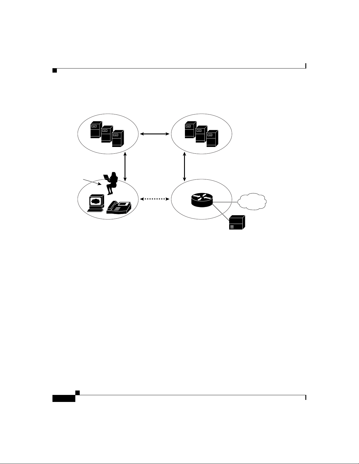
also be grouped into two categories: clients and servers. Figure 1-1 illustrates the
architecture of a SIP ne twork.
What is Session Initiation Protocol?
Note
In addition, the SIP servers can interact with other application
services, such as Lightw eght Direc tory Acce ss Protoc ol (LDAP)
servers, a database application, o r an extensible marku p lang uage
(XML) application. These application services provide back-end
services such as directory, authentication, and billing services.
78-10497-02
Cisco SIP IP Phone 7960 Administrator Guide
1-3
Page 22
What is Session Initiation Protocol?
Figure 1-1 SIP Architecture
SIP User
gents (UA)
Chapter1 Product Overview
SIP Proxy and
Redirect Servers
SIP
SIP SIP
SIP Gateway
SIP Client s
PSTN
42870
IP
RTP
Legacy PBX
SIP clients include:
•
Phones—Can act as either a UAS or UAC. Softphones (PCs that have phone
capabilities installed) and Cisco SIP IP phones can initiate SIP requests and
respond to reques ts .
•
Gateways—Provide call control. Gateways provide many services, the most
common being a tra nslation f unction be twee n SIP c onfere ncing e ndpoin ts
and other terminal type s. T his func tion include s transla tion be twee n
transmission formats a nd be twee n com mu nications pr oced ure s. In addition,
the gateway also translates between audio and video codecs and performs call
setup and clearing on both the LAN side a nd the switched- circuit ne twork
side.
1-4
Cisco SIP IP Phone 7960 Administrator Guide
78-10497-02
Page 23

Chapter 1 Product Overvi ew
SIP Server s
What is the Cisco SIP IP Phone 7960?
SIP servers includ e:
•
Proxy server—The proxy server is an intermediate device that receives SIP
requests from a client and then forwards the re quests on the client’s behalf.
Basically, proxy servers receive SIP messages and for ward th em to the next
SIP server in the network. Proxy servers can provide functions such as
authentication, authorization, network access control, routing, reliable request
retransmission, and security.
•
Redirect server—Receives SIP requests, strips out the address in the request,
checks its address tables for any other addresse s that may be mapp ed to the
one in the request, and then returns the results of the address mapping to the
client. Basically, redirect servers provide the client with information about
the next hop or hops that a message should take and then the clien t contacts
the next hop server or UAS directly.
•
Registrar server—Processes requ ests from UACs for registration of their
current location. Registrar servers are often co-located with a redirect or
proxy server.
What is the Cisco SIP IP Phone 7960?
Cisco SIP IP phones 7960 s (he reafter r eferred to a s C isco SIP IP phon es ) are
full-featured telephones that can be plugged directly into an IP network and used
very much like a standard private branch exchange (PBX) telephone. The Cisco
SIP IP phone is an IP telephony instrument that can be used in VoIP networks.
The Cisco SIP IP phone model terminals can attach to the existing in place data
network infrastructure, via 10B aseT /100B ase T interfa ces on an Ethe rnet sw itch.
When used with a voice-capable Ethernet switch (one that understa nds Type of
Service [ToS] bits and can prioritize VoIP traffic), the phones eliminate the need
for a traditional proprietary tele phone set and key system/PBX.
The Cisco SIP IP phone com plies with RFC 25 43.
Cisco SIP IP Phone 7960 Administrator Guide
78-10497-02
1-5
Page 24

What is the Cisco SIP IP Phone 7960?
Figure 1-2 illustrates physical features of the Cisco SIP IP phone:
Figure 1-2 Cisco SIP IP Phone Physical Features
LCD
Chapter1 Product Overview
Line or speed dial
buttons
Footstand
adjustment
Soft keys
i
" button
"
On-screen
mode buttons
Volume
buttons
1-6
Handset
Dialing
pad
•
LCD screen—Deskto p which displays infor mation about your
Cisco SIP IP phone, such as the time, date, your phone number, caller ID,
line/call status and the soft key tabs.
•
Line or speed dial buttons—Opens a new line or speed dials the number on
the LCD screen.
•
Footstand adjustment—Adjusts the an gle of the p hone ba se.
•
Soft keys—Acti v ates the feature d escribed b y the text me ssage directl y abo ve
on the LCD screen.
•
Information (i) button—Pr ovide s online hel p for sele cted ke ys or fea tures and
network statistics about the active call. This feature will be available in a
future rele ase .
Cisco SIP IP Phone 7960 Administrator Guide
Scroll
key
Function
toggles
38007
78-10497-02
Page 25

Chapter 1 Product Overvi ew
•
On-screen mode buttons—Retrieves information about current settings,
recent calls, available services, and voice mail messages.
•
Volume buttons—Adjusts the volume of the handset, headset, speaker, ringer
and adjusts the brightness contrast settings on the LCD screen.
•
Function toggles—Includes these optio ns:
–
–
•
Scroll key—Enables you to move among different soft key options displayed
on LCD screen.
•
Dialing pad—Press the dia l pa d buttons to d ial a p hon e num be r. Dial pad
buttons work exactly like those on your existing telephone.
•
Handset—Lift the handset and press the dial pad numbers to place a call,
review voice mail messages, answer a call, and so on.
Supported Features
What is the Cisco SIP IP Phone 7960?
Headset and speaker—Toggles these functions enabling you to answer
the phone using a headset or speakerphone.
Mute—Stops or resumes voice transmission.
78-10497-02
In addition to the physical features illustrated in Figure 1-2, the
Cisco SIP IP ph one a lso provides the following:
•
An adjustable ring tone
•
A hearing-aid compatible handset
•
Headset compatibility
•
An integrated two-port Ethernet switch that allows the telephone and a
computer to share a single Ethernet jack
•
A direct connection to a 10Bas eT or 10 0Ba seT Ethe rnet (RJ- 45) n etwor k
(half- or full-duplex conn ections a re sup ported )
•
A large (4.25 x 3 in.) display with adjustable contrast
•
G.711 (u-law and a-law) and G.729a audio comp ression
•
IP address assignment—Dynamic Ho st Configuration Protocol (DHCP)
client or manually configured via a local setup menu
Cisco SIP IP Phone 7960 Administrator Guide
1-7
Page 26

What is the Cisco SIP IP Phone 7960?
•
Ability to:
–
–
–
–
–
–
•
In-band dual-tone multifreque ncy (DTMF) sup port for touc h-tone dialing
•
Out-of-band DTMF signaling for codecs that do not tran sport the DTMF
signaling correctly (for example, G.72 9 or G.729A)
•
Local or remote (using the SI P 183 R i nging m essage ) ca ll p rogre ss tone
•
AVT payload type negotiation
•
Network startup via DHC P a nd Trivial File Transfer Protocol (TFTP)
•
Dial plan support that enables automatic dialing and automatic generation of
a secondary dial ton e
•
Current date and time support via Simple Network Time Protocol (SNTP) and
time zone and daylight savings time supp ort
Chapter1 Product Overview
Configure Ethernet port mode and speed
Register with or unregister from a proxy server
Specify a TFTP boot dire ctory
Configure a label for phone ide ntification display p urpose s
Configure a name for caller identification purposes for each active line
on a phone
Configure a 12- or 24-hour user interfac e time disp lay
1-8
•
Call redirection information supp ort via the CC-Diversion head er
•
Third-party call control via d elayed media negotia tion. A de layed m edia
negotiation is one where the Session Description Protocol ( SDP) informati on
is not completely advertised in the initial call setup.
•
Support for endpoints specified as Fully Qualified Domain Names (FQDNs)
in the SDP
•
Local directory configuration (save and rec all) a nd auto matic dial
completion—Each time a call i s successfully made or recei v ed, the number is
stored in a local dir ector y th at is mainta ined o n the pho ne . The maximu m
number of entries is 32. Entries are aged-out based on their usage and age.
The oldest entry called the least number of times is overwritten first. This
feature cannot be programmed by the user, however, up to 20 entries can be
“locked” (via the Locked soft key) so that they will never be deleted.
Cisco SIP IP Phone 7960 Administrator Guide
78-10497-02
Page 27

Chapter 1 Product Overvi ew
•
•
•
•
What is the Cisco SIP IP Phone 7960?
Message Waiting Indication (via unsolicited NOTIFY)—Lights to indicate
that a new voice m essage is in a subscriber’ s mailbox. If the subscriber listens
to the message but does not save or delete the message, the light remains on.
If a subscriber listens to the new message or messages, and saves or deletes
them, the light goes off. The message waiting indicator is controlled by the
voicemail server.
Speed dial to voicemail via the messages button
Remote reset support (via the E vent header in NOTIFY messa ges)
The following call options:
–
Call forward (network)—A llows the Cisco SIP IP phon e user to re qu est
forwarding service from the network (v ia a third party tool that en ables
this feature to be c onfigured). When a call is placed to the user ’s phone,
it is redirected to the appropriate forward destination by the SIP proxy
server.
–
Call hold—Allows the Cisco SI P IP phone u ser (use r A) to pla ce a ca ll
(from user B) on hold. When user A places user B on hold, the 2-way RTP
voice path between user A and user B is temporarily disconnected but the
call session is still connected. When user A takes user B off hold, the
2-way RTP voice path is reestablished.
78-10497-02
–
Call transfer—Allows the Cisco SIP IP phone user (user A) to transfer a
call from one user (u ser B ) to a nothe r use r (user C) . U ser A p lac es user
B on hold and calls use r C. If user C a ccepts th e transfe r, a session is
established between u ser B and use r C a nd the s ession betw een user A
and user B is terminated.
–
Three-way calling—Allows a “bridged” 3-way call. When a 3-way call
is established, the Cisco SIP IP phone through which the call is
established acts as a bridge, mixing the audio media for the other parties.
–
Do not disturb—Allows the user to instruct the system to intercept
incoming calls during specified periods of time when the user does not
want to be disturbed.
–
Multiple directory numbers—Allows the Cisco SIP IP phone to have up
to six directory numbers or lines.
–
Call waiting—Plays an audible tone to indicate that an incoming call is
waiting. The user can then put the existing call on-hold and accept the
other call. The user can alternat e betwee n the two calls .
Cisco SIP IP Phone 7960 Administrator Guide
1-9
Page 28

What is the Cisco SIP IP Phone 7960?
–
–
–
–
Chapter1 Product Overview
Direct number dialing—Allows users to initiate or receive a call using a
standard E.164 number format in a local, national, or international
format.
Direct URL dialing—Provides the ability to place a call using an email
address instead of a phone number.
Caller ID blocking—Allows the user to instruct the system to block their
phone number or e mail a ddr ess f rom p hone s th at have caller
identification capabilities.
Anonymous call blocking—Allows the user to ins truct the sy stem to
block any calls for which the identification is blocked.
Note
For information on how to use the standard telephony
features and URL dialing, refer to the Getting Started
Cisco IP Phone 7960 a nd Quick Reference Cisco IP
Phone 7960 documents that shippe d w ith the p hon e.
Supported Protocols
The Cisco SIP IP phone s upports the fo llowing standard pr otoc ols:
•
Domain Nam e Syst em (D NS)
DNS is used in the Internet for translating names of network node s into
addresses. SIP uses DNS to resolve the host names of end points to IP
addresses.
•
Dynamic Host Control Protocol (DHCP)
DHCP is used to dynamically allocate and assign IP addresses. DHCP allows
you to move network devices from one subnet to another without
administrative attention. If using DHCP , you can connect Cisco SIP IP phones
to the network and become operational without having to manually assign an
IP address and additional network parameters.
The Cisco SIP IP phone complies with the DHCP specifications documented
in RFC 2131. By default, Cisco SIP IP phones are DHCP-enabled.
1-10
Cisco SIP IP Phone 7960 Administrator Guide
78-10497-02
Page 29

Chapter 1 Product Overvi ew
•
•
•
•
What is the Cisco SIP IP Phone 7960?
Internet Control Message Protocol (ICMP)
ICMP is a network layer Interne t protocol that enables hosts to send error or
control messages to other hosts. ICMP also provides other inform ation
relevant to IP packet processing.
The Cisco SIP supports I CMP as it is docum en ted in RFC 792 .
Internet Protocol (IP)
IP is a network layer protocol that sends datagram packets between nodes on
the Internet. IP also provides features for addressing, type-of-service (ToS)
specification, fragmentation and reassembly, and security.
The Cisco SIP IP phone s upports IP a s it is de fined in RFC 79 1.
Real-Time Transport Protocol (RTP)
RTP transports real-time data (such as voice data) over data networks. RTP
also the ability to obtain Quality of Service (QoS) information.
The Cisco SIP IP phone s upports RTP as a media channel .
Session Description Protoco l (SDP )
SDP is an ASCII-based protocol that describes multimedia sessions and their
related scheduling information.
78-10497-02
The Cisco SIP IP phone us es SD P for se ssion de scr iption.
•
Simple Network Time Protocol (SNTP)
SNTP sychronizes computer clocks on an IP network. The Cisco SIP IP
phones use SNTP for their date and time support.
Cisco SIP IP Phone 7960 Administrator Guide
1-11
Page 30

Prerequisites
•
•
Prerequisites
For the Cisco SIP IP phone to su cce ssfully ope rate as a SIP e ndpoint in y our
network, your network must meet the following requirements:
•
Chapter1 Product Overview
Trivial File Transfer Protocol (TFTP)
TFTP allows files to be transferred from one computer to another over a
network.
The Cisco SIP IP phone us es T FTP to d ownload configuration files and
software updates.
User Datagram Pr otocol (UD P)
UDP is a simple protocol that exchanges data packets witho ut
acknowledgments or guaranteed delivery . SIP can use UDP as the underlying
transport protocol. If UDP is use d, r etran smissions are u sed to en sure
reliability.
The Cisco SIP IP phone s upports UD P as it is d efined in RFC 76 8 for SIP
signaling.
A working IP network is established.
1-12
For more informati on abou t configuri ng IP, refer to Cisco IOS IP and IP
Routing Configuration Guide.
•
VoI P is con figured on you r Cisco r outers.
For more information about configuring VoIP, refer to the Cisco IOS
Release 12.1 Multiservice Applications Configuration Guide for the
appropriate access platfor m. For more informa tion about configurin g SIP
VoIP, refer to the Enhancements to SIP for VoIP on Cisco Access Platforms.
•
VoI P ga teways are co nfigured fo r SIP.
•
A TFTP server is active and contains the latest Cisco SIP IP phone firmware
image in its root directory.
•
A proxy server is active and conf ig ured to r eceive and forw ar d SIP messages.
Cisco SIP IP Phone 7960 Administrator Guide
78-10497-02
Page 31

Chapter 1 Product Overvi ew
Cisco SIP IP Phone Connections
The Cisco SIP IP phone has connec tions for c on necting to th e data network, f or
providing power to the phone, and for connecting a head set to the phone.
Figure 1-3 illustrates the connections on the Cisco SIP IP phone.
Figure 1-3 Cisco SIP IP Phone Cable Connections
Cisco IP Phone 7960 (rear view)
Power
outlet
AC adapter
port
(DC48V)
(optional power
cable)
Cisco SIP IP Phone Connections
Headset
port
RJ-11 port
Connecting to the Network
The Cisco SIP IP phone has two RJ-45 ports that each support 10/100 Mbps halfor full-duplex Ethernet co nnec tions to exter nal devices—networ k port (la beled
10/100 SW) and ac cess port ( labe led 1 0/100 PC) . You can use either
Category 3 or 5 cabling for 10 Mp bs con nection s, but use C ategory 5 f or 100
Mbps connections. On both the network port and access por t, use full- duplex
mode to avoid collisions.
78-10497-02
Network port
(10/100 SW)
Cisco SIP IP Phone 7960 Administrator Guide
Access port
(10/100 PC)
Handset
port
38006
1-13
Page 32

Cisco SIP IP Phone Connectio ns
Network Port (10/100 SW)
Use the network port to connect the phone to the network. You must use a
straight-through cable on this port. The ph one can also obta in inline power from
the Cisco Catalyst switch over this connection. See the “Connecting to Power”
section on page 1-14 for de tails.
Access Port (10/100 PC)
Use the access port to connect a netw ork de vice, such as a compute r , to the phone.
You must use a straight-through cable on this port.
Connecting to Power
The Cisco SIP IP phone can be powered by the following sources:
•
External power source—Optional Cisco AC adaptor and power cord for
connecting to a standard wall receptacle.
•
WS-X6348-RJ45V 10/100 switchin g modu le—P rovides inline power to the
Cisco SIP IP phone when connected to a Catalyst 3500, 4000, or 6000 family
10/100BaseTX switching mo dule.
Chapter1 Product Overview
1-14
This module sends p ower on p ins 1 & 2 and 3 & 6 .
•
WS-PWR-PANEL—Power patch panel provides power to the Cisco SIP IP
phone which allows the Cisco SI P IP ph one to be con necte d to existing
Catalyst 4000, 5000, and 6000 family 10/100BaseTX switc hing modules.
This module sends p ower on p ins 4 , 5, 7, a nd 8.
•
WS-X4148-RJ45V—48 por t 10 /100 Ether net w ith inline power modu le for
the Catalyst 4006.
•
WS-X4095-PEM—VoIP DC Power Entry module for the Cata lyst 4 006.
•
WS-X4608-2PSU and WS-X46 08—External -48V DC power shelf common
equipment for the Catalyst 4006 with two AC-to-DC PSUs and one empty bay
for redundant option and the 110V 15A AC-to48V DC PSU redundant option
for the power shelf
•
WS-C3524-PWR-XL-EN—C atalyst 3524-PWR X L switch
Cisco SIP IP Phone 7960 Administrator Guide
78-10497-02
Page 33

Chapter 1 Product Overvi ew
Cisco SIP IP Phone Connections
Note
Only the network port (labeled 10/10 0 SW) supports inline power
from the Cisco Catalyst switches.
For redundancy, you can use the Cisco AC adapter even if you are using inline
power from the Cisco Catalyst switches. The Cisco SIP IP phone can share the
power load being used from the inline power and external power source. If either
the inline power or the external power goes down, the phone can switch entirely
to the other power source.
T o use this redundancy feature you must set the inline power mode to auto on the
Cisco Catalyst switch. Next, connect the un-powered Cisco SIP IP phone to the
network. After the p hone powers up, c onne ct the extern al power s upply to the
phone.
Using a Headset
The Cisco SIP IP phone supports a four or six-wire headset jack. Specifically , the
Cisco SIP IP phone suppo rts the following Plantron ics he ad set mod els:
•
•
•
The Volume and Mute controls will also adjust volume to the earpiece and mute
the speech path of the headset. The headset activation key is located on the front
of the Cisco SIP IP phone.
Tristar Monaural
Encore Monaur al H 91
Encore Binaural H101
78-10497-02
Note
When using a headset, an amplifier is not required. However, a coil
cord is required to connect the headset to the headset port on the
back of your Cisco IP Phone 7960. For inform ation on ordering
compatible headsets and coil cords for the Cisco IP phone 7960, see
http://cisco.getheadsets.com.
Cisco SIP IP Phone 7960 Administrator Guide
1-15
Page 34

Chapter1 Product Overview
The Cisco SIP IP Phone with a Catalyst Switch
The Cisco SIP IP Phone with a Catalyst Switch
To function in the IP telepho ny network, the C is co SIP IP phone must b e
connected to a networking device, such as a Catalyst switch, to obtain network
connectivity.
The Cisco SIP IP phone has an internal Ethernet switch, which enables it to switch
traffic coming from the phone, ac cess p ort, and the n etwor k por t.
If a computer is connected to the access port, packets traveling to and from the
computer and to and from the phone share the same p hysical link to the switch
and the same port on the s witc h.
This configuration has these implications for the VLAN configuration on the
network:
•
The current VLANs might be configured on an IP subnet basis, and additional
IP addresses might not b e available to assign the ph one to a po rt so that it
belongs to the same subnet as other devices (PC) connected to the same port.
•
Data traffic present on the VLAN supporting phones might reduce the quality
of VoIP traffic.
1-16
Yo u can resolve these issues by isolating the voice traffic onto a separate VLAN
on each of the ports connected to a phone. The switch port configured fo r
connecting a phone would have separate VLANs co nfigured for carr ying:
•
Voic e tra ffic to and fr om the C isco SIP IP pho ne (aux iliary VLA N)
•
Data traffic to and from the PC connected to the switch through the access
port of the Cisco SIP IP phone (na tive VLAN)
Isolating the phones on a separate, auxiliary VLAN increases the quality of the
voice traffic and allows a large number of phones to be added to an existing
network where ther e ar e not en ough I P add re sses .
For more information, refer to the documentation included with the
Cisco C atalyst switch.
Cisco SIP IP Phone 7960 Administrator Guide
78-10497-02
Page 35

CHAPTER
2
Getting Started with Your
Cisco SIP IP Phone
This chapter explains the Cisco SIP IP phone initialization and the process that
you should follow to install and c onnec t the Cisco SIP IP pho ne.
This chapter provides the following major sections:
•
Initialization Process Overview, page 2 -1
•
Installing the Cisco SIP IP Pho ne , pa ge 2-3
•
Verifying Startup, page 2-20
•
Using the Cisco SIP IP Phone Menu Interface, page 2-21
•
Reading the Cisco SIP I P Pho ne I cons, pa ge 2-22
•
Customizing the Cisco SIP IP Phone Ring Types, page 2-24
•
Creating Dial Plans, pa ge 2-24
Initialization Process Overview
The initialization process of the Cisco SIP IP phone is responsible for establishing
network connectivity and fo r making the p hone opera tional in you r IP netwo rk.
Once you connect your phone to the network and to an electrical supply, the phone
begins its initialization process.
Cisco SIP IP Phone 7960 Administrator Guide
78-10497-02
2-1
Page 36

Initialization Process Overview
During the initialization process, the following events take place:
1.
2.
3.
4.
Chapter 2 Getting Started with Your Cisco SIPIP Phone
The stored image is loaded.
The Cisco SIP IP phone has non-volatile Flash memory in which it stores the
firmware images, u ser-defined pre fer ence s, and pe rmane nt fac tory
information about the phone.
During initialization, the phone runs a bootstrap loader that loads and
executes the phone image stored in Flash memory.
The VLAN is configured.
If the Cisco SIP IP phone is connected to a Catalyst switch, the switch notifies
the phone of the voice VLAN defined on the switch. The phone needs to know
its VLAN membership before it can procee d with the DH CP request f or its IP
settings (if using DHCP).
An IP address is acquired.
If the Cisco SIP IP phone is using DH CP to obtain the IP settings, the phone
queries the DHCP server. If the phone is not using DHCP , then the phone will
use IP settings th at are st ored in Fl ash memo ry.
The TFTP se rver is co n tac ted .
2-2
On the TFTP server is the latest Cisco SIP IP phone firmware image and the
dual boot file (OS79XX.TXT) that enables the phone to automatically
determine and initialize for the VoIP environment in which it is being
installed.
If the phone is using the TFTP server to obtain its SIP parameters, there
should also be a configuration file or files on the TFTP server that the phone
will request and download. In the configuration file or files, SIP parameters
that are required by the phone to operate in a SIP VoIP environment are
defined. If the phone is not obtaining its SIP parameters via the TFTP server,
the phone will use SIP settings that are stored in Flash memory.
5.
The firmware vers io n is ve rified.
If the phone is obtaining its SIP parameters via a TFTP server, the
configuration files are requested. If the phone deter mines that the ima ge
defined in a configuration file differs from the imag e it ha s store d in Fla sh
memory, it performs a firmware upgrad e.
When performing a firmware u pgr ad e, the pho ne downlo ad s the firmware
image from the TFTP server, programs the image into Flash memory, and
reboots.
Cisco SIP IP Phone 7960 Administrator Guide
78-10497-02
Page 37

Chapter 2 Getting Started with Your Cisco SIP IPPhone
Installing the Cisco SIP IP Phone
This section contains in forma tion on how to install Cisc o SIP IP p hon es in your
IP network. Before getting started, read over the information in this section
carefully.
Installation Task Summary
To successfully install the Cisco SIP IP phone, you must complete the following
tasks:
1.
Download the required files from CCO to the TFTP server as described in the
the “Downloading Files to Your TFTP Server” section on pag e 2-4.
2.
If you are configuring SIP parameters via a TFTP server, create and store the
configuration files as described in the “Co nfiguring SIP Parame ter s via a
TFTP Server” section on page 2-6.
3.
If you are using DCH P to co nfigure th e pho ne s’ n etwork s ettings, c onfigure
the required network pa ra meter s o n y our D HCP s er ver as d escrib ed in th e
“Configuring Network Parameters via a DHCP Server” section on page 2-14.
Installing the Cisco SIP IP Phone
78-10497-02
4.
Connect the phone to the network and to a power supply as described in the
“Connecting the Phone” sec tion on page 2-16.
5.
If you are not using DHCP to configure network param eters, manua lly
configure the required network parameters as described in the “Manually
Configuring the Network Parameter s” section on page 2-14 .
6.
If you are not configurin g the SIP par ame ters via a TF TP server, manually
configure the required parameters as described in the “Manually Confi guring
the SIP Parameters” section on page 2-11.
Cisco SIP IP Phone 7960 Administrator Guide
2-3
Page 38

Chapter 2 Getting Started with Your Cisco SIPIP Phone
Installing the Cisco SIP IP Phone
Downloading Files to Your TFTP Server
Before installing the Cisco SIP IP phones, c opy the following files from CCO to
the root directory of you r TFT P server.
File Description
OS79XX.TXT (Required) Enables the phone to automatica lly
determine and initialize for the VoIP environment in
which it is being installed.
After downloading this file, you will need to use an
ASCII editor to open it and specify the file name
(without the file extension) of the image version that
you plan to run on you r pho nes .
SIPDefaultGeneric.cnf (Optional) File in which to configure SIP parameters
intended for all phones.
For more information on using the SIPDefault.cnf
file, see the “Creating the Default SIP Configuration
File” section on page 2-7.
SIPConfigGeneric.cnf (Required) File which ca n be us ed as a temp late to
configure SIP parameters specific to a phone. When
customized for a phone, this file must be renamed to
the MAC address of the phone.
RINGLIST.DAT (Optional) Lists audio files that are the custom ring
type options for the phones. The audio files listed in
the RINGLIST.DAT file must also be in the root
directory of the TFTP server.
For more information on custom ring types, see the
“Customizing the Cisco SIP IP Phone R ing Types”
section on page 2-24.
P0S3xxyy.bin
(where xx is the v ersion
number and yy is the
subver s i o n n umber)
dialplan.xml (Optional) North American example dial plan.
syncinfo.xml (Optional) Controls the image version and associated
(Required) The C isco SIP IP pho ne firmware ima ge.
sync value to be used for re mo te re boo ts.
2-4
Cisco SIP IP Phone 7960 Administrator Guide
78-10497-02
Page 39

Chapter 2 Getting Started with Your Cisco SIP IPPhone
Configuring SIP Parameters
Installing the Cisco SIP IP Phone
Note
This section describes how to configure the b asic SI P param eters
that are required for the phone to operate in a SIP VoIP environment.
For a complete list of the SIP parameters that you can configure, see
the “Modifying the Phone’s SIP Settings” section on page 3-5.
The SIP parameter s are tho se pa rame te rs th at a Cisc o SIP I P ph one n eeds to
operate in a SIP V oIP en vironment. You can configure SIP parameters via a TFTP
server or you can manually configure the parameters on a phone-by-phone basis
after connecting the phone s.
When the phone initializes, it loads the parameters stored in Flash memory . After
loading the parameters stored in Flash memory, the phone requests the default
configuration file from the T FTP se rv e r. If the def ault configuration file has been
configured and stored in the root directory of the TFTP ser ver , th e phone re ads the
parameters defined in the file, and stores those parameters that differ in Flash
memory. The phone then requests its phone-specific configuration file. If the
phone-specific configuration file has been c onfigured and pla ced on the TFTP
server (in the root direc tory o r a subd irector y), the pho ne rea ds th e para meter s
defined in the file and stores those parameters that differ in Flash memory.
Therefore, when co nfiguring SI P p aram eters, rem embe r the fo llowing:
•
Parameters defined in the default configuration file will override the values
stored in Flash memory.
•
Parameters defined in the phone-spe cific configuration file will override the
values specified in the default configuration file.
•
Parameters entered locally will be used by the phone until the next reboot (if
a phone-specific configuration file exists).
78-10497-02
•
If you choose not to configure the phone via a TFTP server, you must manage
the phone locally.
Cisco SIP IP Phone 7960 Administrator Guide
2-5
Page 40

Chapter 2 Getting Started with Your Cisco SIPIP Phone
Installing the Cisco SIP IP Phone
Configuring SIP Parameters via a TFTP Server
If you are co nfiguring SIP p ar ameters via a T FTP server, you must u se
configuration files.
There are two co nfiguration files that you can use to define the SIP p aramete rs;
the default configuration file (optional) and the phone-specific configuration file
(required). If you choose to use a default configuration file, you must store the file
in the root directory of your TFT P s er ver. Phone-specific configuration files can
be stored in the root director y or in a subd irec tory in whic h all p hon e-spe cific
configuration file s ar e s tore d .
Except for parameters used to defined the lines and users on a phone, all other SIP
parameters can be defined in either the default configuration file or the
phone-specific configuration file. However, for network control and maintenance
purposes, we recommend that you define the parameters that you want to apply to
all phones in the default configuration file (SIPDefault.cnf). Phone-specific
parameters should only be defined via a phone- specific configuration file or
manually configured. Phone-speci fic parameters should not be defined in the
default configuration file.
Configuration File Guidelines
When modifying the default configuration file and creating the phone-specific
configuration files, adhere to the following guidelines and requirements:
•
SIP parameters specified in the default configuration file (SIPDefault.cnf)
will override those parameters stored in Flash memory. Parameters specifi ed
in a phone-specific configuration file will override those stor ed in Flash
memory and parameters specified in the default configuration file.
•
The name of each pho nes ’ ph one-sp eci fic configuration file is unique an d is
based on the MAC address of the phone.
The format o f th e file n am e mu st be “ S IP X XXXYYYYZZZZ.cnf” w h er e
XXXXYYYYZZZZ is the MAC address of the phone. The MAC address must
be in uppercase and the extension, cnf , mus t be in lower ca se (for exam ple,
SIP00503EFFD842.cnf).
Note
Cisco SIP IP Phone 7960 Administrator Guide
2-6
The MAC address of a phone is identified on the middle
sticker adhered to the base of the phone and ca n also be
viewed on the Network Configuration menu.
78-10497-02
Page 41

Chapter 2 Getting Started with Your Cisco SIP IPPhone
•
The default configuration file must be stored in the root directory of the TFTP
server. The phone-specific configuration file can be stored in the root
directory or in a subdirectory in which all pho ne-spe cific configuration files
are located.
•
Each line in the configuration files must use the following format:
variable-name : value ; optional comments
•
Use colons to separa te variable na mes an d values.
•
Only one value can be associated with a variable.
•
The variab le and va lue can ha ve as muc h white space before or af ter them and
can contain any char acte rs. However, if white spaces ar e need ed wi thin the
value, the value must be enclose d in single or do uble qu ote s. If the value is
enclosed i n quo tes , t he e nd qu ote mu s t be th e s a me a s t h e st ar t qu ot e.
•
After the value, you can include optional comments. Use the semicolon (;)
and pound (#) delimiters to distinguish the comments.
•
Blank lines ar e allowed.
•
Comment lines are a llowed.
Installing the Cisco SIP IP Phone
•
Variable names are not case sensitive.
•
Only one variable can be set per line.
•
Distinguish the end of a line using <lf> or <cr><lf> .
•
The variable and value must be on the same line and cannot break the line.
•
Except for parameters used to defined the lines and users on a phone, all other
SIP parameters can be defined in either the default configuration file or the
phone-specific configuration file. However, for network control and
maintenance purposes, we rec ommen d that you define the parameters tha t
you want to apply to all phones in the default configuration file
(SIPDefault. cn f).
Creating the Default SIP Configuration File
In the default configuration file (SIPDefault.cnf), we recommend that you define
the SIP parameters that will be common to all of your phones such as the
image_version parameter and call environment parameters (for example, will the
phones be required to register with a proxy server and which codec will the
phones use when initiating a call).
78-10497-02
Cisco SIP IP Phone 7960 Administrator Guide
2-7
Page 42

Installing the Cisco SIP IP Phone
By maintaining these parameters in the default conf iguration file, you can perform
global changes, such as upgrad ing the image version, w ithout having to modify
the phone-specific configuration file for e ach pho ne.
Before You Begin
•
Ensure that you have downloaded the SIPDefault.cnf file from CCO to the
root directory of your T FTP server.
•
Review the guidelines and restrictions documented in the “Configuration File
Guidelines” section on page 2-6.
•
For a complete list of the SIP parameters that you can configure, see the
“Modifying the Phone’s SIP Settings” section on p age 3-5.
Procedure
Chapter 2 Getting Started with Your Cisco SIPIP Phone
Step 1
Step 2
Using an ASCII editor, open the SIPDefault.cnf file and define values for the
following SIP global parameters:
•
image_version—(Required) Firmware vers ion th at the Cisco SI P IP phone
should run.
Enter the name of the image ve rsion ( as it is re lea sed by Cisco). Do not enter
the extension. Y ou cannot change the image version by changing the file name
because the version is also built into the file header. Trying to change the
image version by changing the f ile name will cause the fir mware to fa il when
it compares the version in the header against the file name.
•
proxy1_address—(Required) IP address of the primary SIP proxy server that
will be used by the phones. Enter this address in IP dotted-decimal notation.
•
tftp_cfg_dir—(Required if phone-specific configuration files are located in a
subdirectory) Path to the TFTP s ubdir ector y in whic h phon e- specific
configuration files ar e store d.
Save the file with the same file name, SIPDefault.cnf, to the root directory of your
TFTP server.
2-8
Cisco SIP IP Phone 7960 Administrator Guide
78-10497-02
Page 43

Chapter 2 Getting Started with Your Cisco SIP IPPhone
The following is an example of a SIP d efau lt co nfiguration file:
; sip default configuration file
Installing the Cisco SIP IP Phone
#Image Version
image_version:P0S3
#Proxy server address
proxy1_address: 192.168.1.1 ;
#Subdirectory config file location
tftp_cfg_dir: /tftpboot/configs/sipphone
xxyy
;
Creating the Phone-Specific SIP Configurat ion File
In the phone-specific SIP configuration file, define the parameters that are
specific to a phone such as the lines configured on a phone and the users defined
for those lines.
Before You Begin
•
Review the guidelines and restrictions documented in the “Configuration File
Guidelines” section on page 2-6.
•
Line paramete rs (t h ose id en ti fied as li nex) define a line on the phone. If you
configure a line to use an e-mail address, that line can be called only using an
e-mail address. Similarly , if you configure a line to use a number, that line can
only be called using the number. Each line can have a different proxy
configured.
•
For a complete list of the SIP parameters that you can configure, see the
“Modifying the Phone’s SIP Settings” section on p age 3-5.
78-10497-02
Cisco SIP IP Phone 7960 Administrator Guide
2-9
Page 44

Installing the Cisco SIP IP Phone
Procedure
Chapter 2 Getting Started with Your Cisco SIPIP Phone
Step 1
Step 2
Using an ASCII editor, create a phone-specific configuration file for each phone
that you plan to install. In the phone-specific configuration file, def ine values for
the following SIP parameters (where x is a number 1 through 6):
•
linex_name—(Required) Number or e-mail address used when registering.
When entering a num ber, enter the nu mber with out an y dashe s. F or e xam ple,
enter 555-1212 as 5551 212 . When en terin g an e- mail a ddr ess , ente r the
e-mail ID without the host name.
•
linex_authname—(Required when registration is enabled and the proxy
server requires authentication) Name used by the phone for authentication if
a registration is challenged by the proxy server during initialization. If a v alue
is not configured for the linex_authname parameter when registra tion is
enabled, the default name is used. The default name is UNPROVISIONED.
•
linex_password—(Required when registration is enab led and the proxy
requires authentication) Password used by the phone for authentication if a
registration is challenged by the proxy server during initialization. If a value
is not configured for the linex_password parameter when registratio n is
enabled, the default logical password is used. The default logical password is
UNPROVISIONED.
Save the file to your TFTP server (in th e roo t dir ect ory or a subdir ector y
containing all the phone-specific configuration files). Name the file
“SIPXXXXYYYYZZZZ.cnf” where XXXXYYYYZZZZ is the MAC address of the
phone. The MAC address must be in uppercase and the extension, cnf, must be in
lower case (for example, SIP00503EFFD842.cnf) .
2-10
The following is an example of a configuration file:
; phone-specific configuration file sample
; Line 1 phone number
line1_name : 5551212
; Line 1 name for authentication with proxy server
line1_authname : 5551212
; Line 1 authentication name password
line1_password : password
Cisco SIP IP Phone 7960 Administrator Guide
78-10497-02
Page 45

Chapter 2 Getting Started with Your Cisco SIP IPPhone
Manually Configuring the SIP Parameters
If you did not conf igure the SIP pa rameters via a TFT P server , yo u must manually
configure them after you have connected the phone as descr ibed in the
“Connecting the Phone” sec tion on page 2-16.
Before You Begin
•
Connect your phone as described in the “Conne cting the Phone” sectio n on
page 2-16.
•
Unlock configuration mode as de scribe d in th e “Unlo ck ing C onfiguration
Mode” section on page 3-2. By default, the SIP parame ters are locked to
ensure that en d-us ers ca nnot mo dify settin gs that might affect their call
capabilities.
•
Review the guidelines on using the Cisco SIP IP phone menus documented in
the “Using the Cisco SIP IP Phone Menu Interface” section on page 2-21.
•
When configuring the Prefe rred Co dec an d Out of Ba nd D T MF pa rame ter s,
press the Change soft key until the option you desire is displayed and then
press the Save soft key.
Installing the Cisco SIP IP Phone
78-10497-02
Step 1
Step 2
Step 3
Step 4
•
After making your ch ang es, r elo ck c onfiguration m ode as de scr ibed in the
“Locking Configuration Mode ” se ction o n p ag e 3-2.
•
For a complete list of the SIP parameters that you can configure, see the
“Modifying the Phone’s SIP Settings” section on p age 3-5.
Procedure
Press the settings key. The Settings menu is displayed.
Highlight SIP Configuration. The SIP Configuration menu is displa yed.
Highlight Line 1 Settings.
Press the Select soft key. The Line 1 Con figuration menu is d isplay ed.
Cisco SIP IP Phone 7960 Administrator Guide
2-11
Page 46

Installing the Cisco SIP IP Phone
Chapter 2 Getting Started with Your Cisco SIPIP Phone
Step 5
Step 6
Step 7
Step 8
Highlight and press the Select soft key to configure the fo llowing param eters:
•
Name—(Required) Number or e-mail addre ss used when registering. Whe n
entering a number, enter the number without a ny dashes. For examp le, enter
555-1212 as 5551212. When e nteri ng an e -mail ad dress, en ter th e e-m ail ID
without the host name.
•
Authentication Name—(Required when registration is enabled) Name used
by the phone for authentication if a registration is challenged by the proxy
server during initialization. If a val ue is not configured for the Authentication
Name parameter when registration is enabled, the default name is used. The
default name is SIPmacaddr ess wh ere macaddress is the MAC address of the
phone.
•
Authentication Password—(Required when registration is enabled) P assword
used by the phone for authentication if a registration is challenged by the
proxy server during initialization. If a value is not configured for the
Authentication Password parameter when registration is enabled, the default
logical password is used. The default logical password is SIPmaca ddress
where macaddress is the MAC address of the phone.
•
Proxy Address—(Req uire d for the first line configured o n th e pho ne) I P
address of the primary SIP proxy server that will be used by the phone. Enter
this address in IP dotted-decimal notation.
Press the Back soft key to exit the Line 1 C onfiguration m enu.
To configure additional lines on the p hon e, highlight th e next Line x Settings,
press the Select soft key and repeat Step 5 and Step 6.
When done, p res s th e Save soft key to save your changes and exit the
SIP Configuration menu.
2-12
Caution
When you have completed your changes, ensure that yo u lock the
phone as described in the “Locking Configuration Mode” section on
page 3-2.
Cisco SIP IP Phone 7960 Administrator Guide
78-10497-02
Page 47

Chapter 2 Getting Started with Your Cisco SIP IPPhone
Configuring Network Parameters
Installing the Cisco SIP IP Phone
Note
This section describes how to configure the b asic n etwork
parameters that are required fo r the phone to operate o n the networ k.
For a complete list of the network parameters that you can configure,
see the “Modifying the Phone’s Network Settings” section on
page 3-2.
The network param eters inclu de those pa rame ters that m ust b e configured on a
phone for the phone to oper ate in a n I P n etwork. You can configure the required
network parameters via D HCP or m anua lly configure the m after you have
connected the phone to a p ower supply.
The following parameters must be defined for your ph one to establish network
connectivity:
•
Phone's IP address
•
Subnet mask
•
Default gateway for the subnet (use “0.0.0.0” if not required)
•
Domain name
•
DNS server IP address (use “0.0.0.0” if not required)
•
TFTP server IP address
When configuring the network parameters of an IP phone, adhere to the following
guidelines:
•
Use 0.0.0.0 for unused IP addr esses.
78-10497-02
•
You can use 0.0.0.0 for the su bnet m ask on ly if the d efault gateway is also
0.0.0.0.
•
The TFTP server m us t h ave a non -zer o IP ad dre ss.
•
The default gateway must be on th e sam e sub net as the p hon e.
•
The default gateway can be 0.0.0.0 only if the TFTP or DNS server is on the
same subnet as the phon e.
Cisco SIP IP Phone 7960 Administrator Guide
2-13
Page 48

Installing the Cisco SIP IP Phone
Chapter 2 Getting Started with Your Cisco SIPIP Phone
Note
By default, DHCP is enabled on your phone. Bef ore you can
manually con figure t he network parameters , you must disa ble DHCP
after connecting your phone to a power supply.
Configuring Network Parameters via a DHCP Server
If you are using DH CP to c onfigure the ne twork p aram ete rs, c onfigure th e
following DHCP options on your DHCP server before you connect your Cisco SIP
IP phone:
•
dhcp option #50 (IP address)
•
dhcp option #1 (IP subnet mask)
•
dhcp option #3 (Default IP gateway)
•
dhcp option #15 (Domain name)
•
dhcp option #6 (DNS server IP address)
•
dhcp option #66 (TFTP ser ver IP addr ess)
Manually Configuring the Network Parameters
If you are not using DCHP to configure your network para meters, yo u must
manually configure them.
2-14
Before You Begin
•
Connect your phone as described in the “Conne cting the Phone” sectio n on
page 2-16.
•
Unlock configuration mode as de scribe d in th e “Unlo ck ing C onfiguration
Mode” section on page 3-2. By default, the network parameters are locked to
ensure that end-users canno t modify settin gs that might affect their network
connectivity.
•
Review the guidelines on using the Cisco SIP IP phone menus documented in
the “Using the Cisco SIP IP Phone Menu Interface” section on page 2-21.
Cisco SIP IP Phone 7960 Administrator Guide
78-10497-02
Page 49

Chapter 2 Getting Started with Your Cisco SIP IPPhone
•
When configuring a domain name:
–
Press the Number soft key if entering a numerical ID or press the Alpha
soft key to enter a name.
–
If entering letters, use the numbers on the dial pad associate d with a
particular letter. For example, the 2 key has the letters A, B, and C. F o r a
lower case “a”, press the 2 key once. To scroll through the available
letters and numbers, press the key repeatedly.
–
Press the << soft key to delete any mistakes.
•
After making your ch ang es, r elo ck c onfiguration m ode as de scr ibed in the
“Locking Configuration Mode ” se ction o n p ag e 3-2.
•
For a complete list of the SIP parameters that you can configure, see the
“Modifying the Phone’s Network Settings” section on p age 3-2.
Procedure
Installing the Cisco SIP IP Phone
Step 1
Step 2
Step 3
Step 4
Step 5
Step 6
Press the settings key. The Settings menu is displayed.
Highlight Network Configuration.
Press the Select soft key. The Network Configuration menu is displayed .
Highlight DHCP Enabled.
Press the No soft key. DHCP is now disabled.
Highlight and configured each of the following parameters:
•
IP Address—IP addr ess of the phon e.
•
Subnet Mask—IP subnet m ask us ed by the ph one .
•
TFTP Server—IP address of the TFT P server from whic h the pho ne
downloads its configuration files and firmware images.
•
Default Routers 1 through 5—IP addre ss of the default gateway used by the
phone. Default Routers 2 through 5 are the IP addresses of the gateways that
the phone will attempt to use as an alternate gateway if the primary gateway
is not available.
78-10497-02
Cisco SIP IP Phone 7960 Administrator Guide
2-15
Page 50

Installing the Cisco SIP IP Phone
•
Domain Name—Name of the DNS domain in which the phone resides.
•
DNS Servers 1 through 5—IP address of the DNS server used by the phone
to result names to IP address es. T he phone will attempt to use DNS Servers
2 through 5 if DN S Se rver 1 is u navailable.
Chapter 2 Getting Started with Your Cisco SIPIP Phone
Step 7
When done, press the Sa ve soft key . The phone programs the ne w information into
Flash memory and resets.
Caution
When you have completed your changes, ensure that yo u lock the
phone as described in the “Locking Configuration Mode” section on
page 3-2.
Connecting the Phone
You must connect the phone to the network and to a power source before using it.
Before You Begin
•
Refer to Figure 2-1 for a graphical overvie w of the procedure s in this section.
2-16
Cisco SIP IP Phone 7960 Administrator Guide
78-10497-02
Page 51

Chapter 2 Getting Started with Your Cisco SIP IPPhone
Figure 2-1 Cisco SIP IP Phone Cable Connections
Power
outlet
AC adapter
port
(DC48V)
(optional power
cable)
RJ-11 port
Installing the Cisco SIP IP Phone
Cisco IP Phone 7960 (rear view)
Headset
port
Handset
port
78-10497-02
Step 1
Step 2
Network port
(10/100 SW)
Access port
(10/100 PC)
38006
Procedure
Connect a Category 3 or 5 straight-through Ethernet cable from the switch or hub
to the network port on the phone .
See “Connecting to the Ne twork ” sec tion on pa ge 1-13 f or mo re inf orm ation on
the network port.
Connect the handset and headset to their respective ports.
See “Using a Headset” section on page 1-15 for more information on the headset
port.
Cisco SIP IP Phone 7960 Administrator Guide
2-17
Page 52

Installing the Cisco SIP IP Phone
Chapter 2 Getting Started with Your Cisco SIPIP Phone
Step 3
Connect a Category 3 or 5 straight-through Ethern et cable from an othe r network
device, such as a desktop computer, to the access port on the phone (o ptiona l).
See “Connecting to the Ne twork ” sec tion on pa ge 1-13 f or mo re inf orm ation on
the access port.
Step 4
Connect the power plug to the Cisco AC Adapter port (optional).
See “Connecting to Power” sec tion on p ag e 1-14 for more in forma tion.
Adjusting the Placement of the Cisco SIP Phone
The Cisco SIP IP phone includes an adjustable footstand. When placing the phone
on a desktop surface, you can adjust the tilt height to several different angles in
7.5 degree increm ents f rom f lat to 60 d egrees. Al tern atively, you can mount the
phone to the wall using the footsta nd or usin g th e option al lo ckin g ac cesso ry.
Adjusting Phone Placement on the Desktop
Adjust the footstand to the height that provides optimum view of the display and
use of the buttons and keys.
To adjust the phone placement on the desktop:
Step 1
Step 2
Push in the footstand adjustment knob.
Adjust the footstand to its desired height and release the knob.
Mounting the Phone to the Wall
You can mount the Cisco SIP IP phone on the wall using the footstand as a
mounting bracket, or using the optional locking bracket. Use the following
procedure to mount the phone on the wall using the standard footstand. T o use the
optional locking bracket, refer to the Installing the Wall Mount Kit for the Cisco
IP Phone docume nt.
Cisco SIP IP Phone 7960 Administrator Guide
2-18
78-10497-02
Page 53

Chapter 2 Getting Started with Your Cisco SIP IPPhone
Before You Begin
•
Mounting the Cisco SIP IP phone on the wall requires some tools and
equipment that are not pr ovided as standa rd e quipm ent.
Following are the tools and parts r equired for a typ ica l Cisco SIP IP phon e
installation:
–
Screwdriver
–
Screws to secure the Cisco SIP IP phone to the wall
•
Refer to Figure 2-1 for a g raphic al overview of these proc edur es.
Procedure
Installing the Cisco SIP IP Phone
Step 1
Step 2
Step 3
Step 4
Step 5
Push in the footstand adjustment knob.
Adjust the footstand so it is flat agai nst the ba ck of the phon e.
Modify the handset rest so that the handset remains on the ear-piece rest when the
phone is vertically placed.
a.
Remove the handset from the ea r-piece re st.
b.
Locate the tab (hands et wa ll h ook) a t the base of the e ar-piece r est.
c.
Slide this tab out, rotate it 180 degrees, and reinsert it.
d.
Place the handset on the ear-piece rest.
Insert two screws into a wall stud, matching them to the two screw holes on the
back of the footstand.
The keyholes fit standard phone jack mounts.
Hang the phone on the wa ll.
78-10497-02
Cisco SIP IP Phone 7960 Administrator Guide
2-19
Page 54

Verifying Startup
Chapter 2 Getting Started with Your Cisco SIPIP Phone
Figure 2-2 Adjusting the Footst and
Cisco IP Phone 7960 (rear view)
Footstand adjustment
button raises and
lowers adjustment
plate
Verifying Startup
After the phone has power connected to it, the phone begins its startup process by
cycling through these steps:
Adjustment plate
installation
screws holes (2)
Adjustment plate
raises and lowers
phone vertically
38036
2-20
1.
These buttons flash on a nd off in sequenc e :
–
Headset
–
Mute
–
Speaker
2.
The Cisco Systems, Inc. copyright displays on the LCD.
Cisco SIP IP Phone 7960 Administrator Guide
78-10497-02
Page 55

Chapter 2 Getting Started with Your Cisco SIP IPPhone
3.
These messages display as phone starts up:
–
Configuring VLAN—The phone is configuring the E ther net conne ction .
–
Configuring IP—The phone is contacting the DHCP server to obtain
network paramete rs an d the IP add ress of the TF TP s erver.
–
Requesting Configuration—The p hone is c on tact ing the TFTP se rver to
request its configuration files and compare firmware images.
–
Upgrading Software—Th e Upgrade Softwa re message displa ys only if
the phone has determine d that an im ag e upg ra de is re quired. Af ter
upgrading the image, the phone will automatically reboot to run the new
image.
4.
The main LCD scr een ap pear s disp layin g:
–
Primary directory numbe r
–
Soft keys
If the phone successfully passes through these stages, it has started up p roperly.
Using the Cisco SIP IP Phone Menu Interface
Using the Cisco SIP IP Phone Menu Interface
As you configure your phone’s settings via the menu interface, f ollow these
guidelines:
•
Select a parameter by pressing the down arrow to scroll to and highlight the
parameter or by pressing the number that represents the parameter (located to
the left of the parameter on the LCD).
•
During configuration, use * fo r do ts (pe riods) o r p ress the “.” soft key when
available on the LCD.
•
Press Cancel during configuration to cancel all changes and exit a menu.
•
When configuring an SIP IP address or ID parame ter:
–
Press the Number soft key if entering a numerical value or press the
Alpha soft key to enter a name.
–
Use the buttons on the dial pad to enter a new value.
Cisco SIP IP Phone 7960 Administrator Guide
78-10497-02
2-21
Page 56

Chapter 2 Getting Started with Your Cisco SIPIP Phone
Reading the Cisco SIP IP Phone Icons
–
If entering letters, use the numbers on the dial pad associate d with a
particular letter. For example, the 2 key has the letters A, B, and C. F o r a
lower case “a”, press the 2 key once. To scroll through the available
letters and numbers, press the key repeatedly.
–
Press the << soft key to delete any mistakes.
•
When configuring an networ k IP addr ess or I D pa ram eter:
–
Use the buttons on the dial pad to enter a new value.
–
Press the << soft key to delete any mistakes.
•
After editing a parameter, press the Validate soft key to save the value that
you have entered and exit the Edit panel.
Reading the Cisco SIP IP Phone Icons
When using the Cisco SIP IP phone, a variety of icons can display on the phone’s
LCD. Table 1 lists and de scri bes e ach icon that you mig ht see w hile usin g the
Cisco SIP IP phone.
2-22
Table 1 Cisco SIP IP Phone User Interface Icon Meanings
Icon Meanin g
The Cisco IP ph one 7 960 tha t yo u ar e using is runn ing SIP.
The line is configured for E.164 number dia ling and you can
enter only numbers when placing the call.
The character “x” displayed to the right of the icon indicates
that registration has failed.
Cisco SIP IP Phone 7960 Administrator Guide
78-10497-02
Page 57

Chapter 2 Getting Started with Your Cisco SIP IPPhone
Table 1 Cisco SIP IP Phone User Interface Icon Meanings (continued)
Icon Meanin g
The line is configured for E.164 number dialing and ready for
you to place the call. When a line is configured for E.164
number dialing, you can enter only number s when p lacing the
call.
You can change to UR L dia lin g at any time while dialing on a
line by pressing the more soft key and then the URL soft key.
The character “x” displayed to the right of the icon indicates
that registration has failed.
The line is configured for URL dialing and you can enter both
numbers and letters when placing the call.
The character “x” displayed to the right of the icon indicates
that registration has failed.
The line is configured f or URL dia ling a nd ready fo r you to
place the call. When a line is configured for URL dialing, you
can enter both numb ers and l ette rs when plac ing th e call .
You can change to E.164 numbe r dialing a t any time while
dialing on a line by pressing the more soft key and then the
Number soft key.
Reading the Cisco SIP IP Phone Icons
78-10497-02
The character “x” displayed to the right of the icon indicates
that registration has failed.
The Cisco SIP IP phone configuration mode is locked. When
the phone is locked, the phone’s network or SIP settings cannot
be modified.
The Cisco SIP IP phone configure mode is unlocked. When the
phone is unlocked, the phone’s network or SIP settings can be
modified.
Cisco SIP IP Phone 7960 Administrator Guide
2-23
Page 58

Chapter 2 Getting Started with Your Cisco SIPIP Phone
Customizing the Cisco SIP IP Phone Ring Types
Customizing the Cisco SIP IP Phone Ring Types
The Cisco SIP IP phone ships with two ring types: Chirp1 and Chirp2. By default,
your ring type options will be those two choices. H owever, using the
RINGLIST.DAT file, you can customize the ring types that are available to the
Cisco SIP IP phone user s.
Step 1
Step 2
Step 3
Create a pulse code modulation (PCM) file of the desired ring types a nd st ore the
PCM files in the root directory of y our TFTP ser ver. PCM files must contain no
header information and comply with the following format guidelines:
•
8000 Hz sampling ra te
•
8 bits per sample
•
ulaw compression
Using a ASCII editor, open the RINGLIST .D AT file and for each of the ring types
you are adding, specify the name as you want it to display on the Ring Type menu,
press Tab, and then specify the filename of the ring type. For example, the format
of a pointer in your RIN GLI ST.DAT file should appe ar simi lar to th e fo llowing:
Ring Type 1 ringer1.pcm
After defining pointers for eac h of the r ing ty pes yo u are ad ding, save your
modifications and close the RINGLIST.DAT file.
Creating Dial Plans
Dial plans enable the Cisco SIP IP phon e to su pport a uto matic d ialing a nd
automatic generation o f a se co ndary dia l ton e. I f a single dial plan is to be us ed
for a system of phones, the dial plan is best specified in the default configuration
file. However, you can create multiple dial plans and specify whic h phones are to
use which dial plan by defining the dial_template parameter in the phone-specific
configuration file. If one phone in a system of phones needs to use a different dial
plan than the rest, you need to define the differing dial plan by specifying the
dial_template parameter in that phone’s phone-specific configuration file.
2-24
Cisco SIP IP Phone 7960 Administrator Guide
78-10497-02
Page 59

Chapter 2 Getting Started with Your Cisco SIP IPPhone
Creating Dial Plans
Note
Step 1
Step 2
Step 3
We recommend that you define the dial_template pa rameter in the
default configuration file for maintenance and control purposes.
Specify the dial_template parameter in a phone-specific
configuration file only if that phone needs to use a different dial plan
than is being used by the other phones in the same system.
When creating a dial plan, remember the following:
•
Dial plans must be in a n .xm l f orm at an d be stored on yo ur TF TP ser ver.
•
You must specify which dial plan a phone is to use by specifying the path to
the dial plan in the dial_template parameter that you define in either the
phone-specific configuration file or the default configuration. We recommend
that the dial_template parameter be defined in the default configuration file
unless a specific phone must u se a dial plan that differs from the one b eing
used by other phones in the same system.
•
<DIALTEMPLATE> indicates the start of a template and
</DIALTEMPLATE> indicates the end of a template
•
Rules are matched from start to finish with the longest matching rule tak en as
the one to use. Matche s again st a period a re no t coun ted for the leng th to be
the longest.
Using an ASCII editor, open a new file.
Type <DIALTEMPLATE> to indicate the start of the dial plan template.
For each of the numbering schemes that you wish to define, add the following
string to the template, each starting each on a separate line:
<TEMPLATE MATCH=”
pattern
” Timeout=”
sec
” User=”
type
” Rewrite=”
altstrng
”
78-10497-02
Where:
•
MATCH=”patter n” is the dial pattern to match. When entering the pattern,
use a period (.) to match any character or use an asterisk (*) to match one or
more characters. To have the phone generate a secondar y dia l tone w hen the
part of the templ ate ma tche s, us e a comm a (,).
•
Timeout=”sec” is the number of seconds before a timeout will occur and the
number will be dialed as entered by the user. To have the number dial
immediately, specify 0.
Cisco SIP IP Phone 7960 Administrator Guide
2-25
Page 60

Creating Dial Plans
Chapter 2 Getting Started with Your Cisco SIPIP Phone
•
User=”type” is the either IP or Phone. Enter User=phone or User=IP to have
the tag automatically added to the dialed number.
•
Rewrite=”altstrng” is the alternate string to be d ialed in stead of what the user
enters.
Step 4
If desired, spec ify <!-- comment--> at the end of each string where comment
defines the type of plan (for example, Long Distance or Corporate Dial Plan).
Step 5
When completed, specify </DIALTEMPLATE> to indicate the end the dial plan
template.
Step 6
Give the file a unique name specific to the dial plan it defines and save the file
with an .xm l ex ten sio n to yo u TFT P se rver.
Step 7
If the dial plan applies to a specific phon e, a dd the path to the dia l plan (withou t
specifying the file type of .xml) via the dial_template parameter in the phone
specific configuration file. If the dial plan applies to a system of phones, add the
path to the dial plan via th e dia l_tem plate par amete r in the d efau lt co nfiguration
file. For more information on defining the dial_template parameter, see the
“Modifying the Phone’s SIP Settings” section on p age 3-5.
The following is an example of a North American dial plan:
Example 2-1 Example of a PBX North American Dial Plan
<DIALTEMPLATE>
<TEMPLATE MATCH="0" Timeout="1" User="Phone"/> <!-- Local operator-->
<TEMPLATE MATCH="9,011*" Timeout="6" User="Phone"/> <!-- International calls-->
<TEMPLATE MATCH="9,0" Timeout="1" User="Phone"/> <!-- PSTN Operator-->
<TEMPLATE MATCH="9,11" Timeout="0" User="Phone" Rewrite="9911"/> <!-- Emergency-->
<TEMPLATE MATCH="w!" Timeout="1" User="PHONE" Rewrite="9911"/> <!-- 911 when entered in
Alpha mode -->
<TEMPLATE MATCH="9,.11" Timeout="0" User="Phone"/> <!-- Service numbers -->
<TEMPLATE MATCH="9,101..............." Timeout="0" User="Phone"/> <!-- Long Distance
Service-->
<TEMPLATE MATCH="9,10.............." Timeout="0" User="Phone"/> <!-- Long Distance
Service-->
<TEMPLATE MATCH="9,10*" Timeout="6" User="Phone"/> <!-- Long Distance Service-->
<TEMPLATE MATCH="9,1.........." Timeout="0" User="Phone"/> <!-- Long Distance -->
<TEMPLATE MATCH="9,......." Timeout="0" User="Phone"/> <!-- Local numbers -->
<TEMPLATE MATCH="*" Timeout="15"/> <!-- Anything else -->
</DIALTEMPLATE>
2-26
Cisco SIP IP Phone 7960 Administrator Guide
78-10497-02
Page 61

Managing Cisco SIP IP Phones
This chapter provides information on the following:
•
Entering Configuration Mode, page 3-1
•
Modifying the Phone’s Network Settings, page 3-2
•
Modifying the Phone’s SIP Settings, page 3-5
•
Setting the Date, Time, and Daylight Savings Time, page 3-22
•
Erasing the Locally -De fined Settings , page 3-28
•
Accessing Status Information, page 3-30
•
Upgrading the Cisc o SIP I P Pho ne Firmwar e , p ag e 3-33
Entering Configuration Mode
CHAPTER
3
78-10497-02
When you access the network c onfiguration infor matio n on y our Cisco SIP IP
phone, you will notice that there is a padlock symbol located in the upper right
corner of your LCD. By default, the network configuration information is locked.
Before you can mod ify any of the netwo rk configuration pa ram eters, you m ust
unlock the phone.
Cisco SIP IP Phone 7960 Administrator Guide
3-1
Page 62

Modifying the Phon e’s Network Settings
Unlocking Configuration Mode
To unlock the Cisco SIP IP p hone , pr es s ** #.
Chapter3 Managing Cisco SIP IP Phones
Note
You have activated the configuration mode for your phone. There is
no indication an action has taken place.
If the Network Configuration or SI P Co nfiguration pa nel is d isplay ed , the loc k
icon in the upper right corner of your LCD will change to an unlocked state. If
you are located elsewhere in the Cisco SIP IP phone menu s, the next tim e you
access the Network Configuration or the SIP Configuration panels, the lock icon
will be displayed in an unlocked state.
The unlocked symbo l indic ates that you can modify the netwo rk an d SI P
configuration settings.
Locking Configuration Mode
To lock the Cisco SIP IP phone when you are done modifying the settings,
press **#.
If the Network Configuration or SI P Co nfiguration pa nel is d isplay ed , the loc k
icon in the upper right corner of your LCD will change to a locked state. If you
are located elsewhere in the Cisco SIP IP phone menus, the next time you access
the Network Configuration or the SIP Configuration panels, the lock icon will be
displayed in a locked state.
The unlocked symbo l indic ates that you can modify the netwo rk an d SI P
configuration settings.
Modifying the Phone’s Network Settings
You can display and configure the network settings of a Cisco SIP IP phone. The
network settings include info rmation suc h as the phone ’s DHCP server, MAC
address, IP address , and doma in name .
Cisco SIP IP Phone 7960 Administrator Guide
3-2
78-10497-02
Page 63

Chapter 3 Managing Cisco SI P IP Phones
Before You Begin
When configuring network settings, remember the following:
•
Unlock configuration mode as de scribe d in th e “ Unlo cking C onfiguration
Mode” section on page 3-2. By default, the network parameters are locked to
ensure that end-users canno t modify settin gs that might affect their network
connectivity.
•
Review the guidelines on using the Cisco SIP IP phone menus documented in
the “Using the Cisco SIP IP Phone Menu Interface” section on page 2-21.
•
After making your ch ang es, r elo ck c onfiguration m ode as de scr ibed in the
“Locking Configuration Mode” se ction on p age 3-2.
Procedure
Modifying the Phone’s Network Settings
Step 1
Step 2
Step 3
Press the settings key. The Settings menu is displayed.
Highlight Network Configuration.
Press the Select soft key.The Network Configuration menu is displayed.
The following network parameters are available on the Network Configuration
menu:
•
DHCP Server—IP address of the DH CP server f rom wh ich the ph one
received its IP address and additional network settings. You cannot change
the information in this field.
•
MAC Address—Factory-assigned unique 48-bit hexadec imal MAC address
of the phone. You cannot change the information in this field.
•
Host Name—Unique host name assigned to the phone. The value in this field
is always SIPmac where mac is the MAC address of the phone. You cannot
change the information in this field.
•
Domain Name—Name of the DNS domain in which the phone resides.
•
IP Address—IP address of the phon e that was assigned by DHCP or locally
configured. To edit this field, DHCP must be disabled.
•
Subnet Mask—IP subnet m ask us ed by the ph one . A subne t m ask p artitions
the IP address into a network and a host identifier. To edit this field, DHCP
must be disabled.
78-10497-02
Cisco SIP IP Phone 7960 Administrator Guide
3-3
Page 64

Modifying the Phon e’s Network Settings
•
TFTP Server—IP address of the TFT P server from whic h the pho ne
downloads its configuration files and firmware images. To edit this field,
DHCP must be disabled.
•
Default Routers 1 through 5—IP addre ss of the default gateway used by the
phone. Default Routers 2 through 5 are the IP addresses of the gateways that
the phone will attempt to use as an alternate gateway if the primary gateway
is NA. To edit this field, DHCP must be disabled.
•
DNS Servers 1 through 5—IP address of the DNS server used by the phone
to result names to IP address es. T he phone will attempt to use DNS Servers
2 through 5 if DNS Server 1 is unavailable. To edit this field, DHCP must be
disabled.
•
Operational VLAN Id—Unique identifier of the VLAN of which the phone is
a member. This identifier is obtained through Cisco Discovery Protocol
(CDP). You cannot change the infor ma tion in this field.
•
Admin. VLAN Id—Unique identifier of the VLAN to which the phone is
attached. The value in this field is only used in non-Cisco switched networks.
You can change the administrative VLAN used by the phone, however, if you
have an administrative VLAN assigned on the Catalyst switch, that setting
overrides any changes made o n the pho ne.
Chapter3 Managing Cisco SIP IP Phones
3-4
•
Network Media Type—Ethernet port negotiation mode. Possible values are
–
Auto—Port is auto-negotiated.
–
Full-100—Port is configured to be a fu ll-dup lex, 100M B con ne ction.
–
Half-100—Port is configured to be a half -duplex, 100 MB conn ec tion.
–
Full-10—Port is configured to be a full-d uplex, 10M B co nne ctio n.
–
Half-10—Port is configured to be a half-duplex, 10MB connection.
The default is Auto.
•
DHCP Enabled—Whether the pho ne w ill use D HCP to c onfigure networ k
settings (IP address, subnet mask, domain name, default router list, DNS
server list, and TFTP address). Possible values for this field are Yes and No.
By default, DHCP is enabled on the phone. To manually configure your IP
settings, you must first disable DHCP.
•
DHCP Address Released—Wh ether the I P a ddre ss of the phone c an be
released for reuse in the network. When you set this field to Yes, the phone
sends a DHCP release message to the DHCP server and goes into a release
state. The release state provide s e nough time to remove the pho ne fr om the
Cisco SIP IP Phone 7960 Administrator Guide
78-10497-02
Page 65

Chapter 3 Managing Cisco SI P IP Phones
network before the phone attemp ts to acqu ire another IP ad dress fro m the
DHCP server. When moving the phone to a new network segment, you should
first release the DHCP address.
•
Alternate TFTP—Whether to use an alter nate TFTP serv er . T his field e nables
an administrator to specify the remote TFTP ser ver rather than the local one.
Possible values for this parameter are Yes and No. The default is No. Wh en
Yes is specified, the IP address in the TFTP Address parameter must be
changed to the address of the alternate TFTP server.
•
Erase Configuration—Whether to erase all of the locally-defined settings on
the phone and reset the values to the defaults. Selecting Yes will re-enable
DHCP. For more information on erasing the local configuration, see the
“Erasing the Locally-Defined Settings” section on page 3-28.
Modifying the Phone’s SIP Settings
Step 4
When done, press the Sa ve soft key . The phone programs the ne w information into
Flash memory and resets.
Caution
When you have completed your changes, ensure that yo u lock the
phone as described in the “Locking Configuration Mode” section on
page 3-2.
Modifying the Phone’s SIP Settings
You can modify the SIP para meter s o f a Cisco SI P IP phone .
When modifying SIP parameters, remember the following:
•
Parameters defined in the default configuration file will override the values
stored in Flash memory.
•
Parameters defined in the phone-spe cific configuration file will override the
values specified in the default configuration file.
•
Parameters entered locally will be used by the phone until the next reboot if
a phone-specific configuration file exists.
•
If you choose not to configure the phone via a TFTP server, you must manage
the phone locally.
78-10497-02
Cisco SIP IP Phone 7960 Administrator Guide
3-5
Page 66

Chapter3 Managing Cisco SIP IP Phones
Modifying the Phone’s SIP Settings
Table 3-1 lists each of the SIP parameters that you can configure. In the
Configuration column, the name of a parameter as you would specif y it in a
configuration file is listed. In the menu column (SIP Configuration, Network
Configuratio n , an d Ser vi ces) , th e nam e of the same par am ete r as i t wo uld appear
on the user interface is listed. If NA appears for a parameter name in a menu
column, it can c ann ot be defined via th at me nu.
Table 3-1 SIP Parameters Summary
Configuration File SIP Configuration Menu Network Configuration
Services Menu
Menu
anonymous_call_block NA NA An onymous Call Block
autocomplete NA NA Auto-Complete
Numbers
callerid_blocking NA NA Caller ID Blo ck
dial_template NA NA NA
dnd_control NA NA NA
dst_auto_adjust NA NA NA
dst_offset NA NA NA
dst_start_day NA NA NA
dst_start_day_of_week NA NA NA
dst_start_month NA NA NA
dst_start_time NA NA NA
dst_start_week_of_monthNA NA NA
dst_stop_day NA NA NA
dst_stop_day_of_week NA NA NA
dst_stop_month NA NA NA
dst_stop_time NA NA NA
dst_stop_week_of_monthNA NA NA
dtmf_avt_payload NA NA NA
dtmf_db_level NA NA NA
dtmf_inband NA NA Do Not Disturb
Cisco SIP IP Phone 7960 Administrator Guide
3-6
78-10497-02
Page 67

Chapter 3 Managing Cisco SI P IP Phones
Modifying the Phone’s SIP Settings
Table 3-1 SIP Parameters Summary (continued)
Configuration File SIP Configuration Menu Network Configuration
Services Menu
Menu
dtmf_outofband O ut of Ba nd DTM F NA NA
image_vers i on NA NA NA
linex_authname
Authen tic a ti o n N a m e NA NA
(line1 to line6)
linex_displayname
Display Name NA NA
(line1 to line6)
linex_name
Name NA NA
(line1 to line6)
linex_password
(line1 to line6)
linex_shortname
Authen tication
NA NA
Password
Shortname NA NA
(line1 to line6)
messages_uri Messages URI NA NA
network_media_type NA Network Media Type NA
phone_label Phone Label NA NA
preferred_codec Preferred Codec NA NA
proxy_register Register with Proxy NA NA
proxy1_address Proxy Addres s NA NA
proxy1_port Proxy Port NA NA
sip_invite_retx NA NA NA
sip_retx NA NA NA
sntp_mode NA NA NA
sntp_server NA NA NA
sync NA NA NA
tftp_cfg_dir TFTP Directory NA NA
time_format_24hr NA NA NA
time_zone NA NA NA
timer_invite_expires NA NA NA
78-10497-02
Cisco SIP IP Phone 7960 Administrator Guide
3-7
Page 68

Chapter3 Managing Cisco SIP IP Phones
Modifying the Phone’s SIP Settings
Table 3-1 SIP Parameters Summary (continued)
Configuration File SIP Configuration Menu Network Configuration
Menu
timer_register_expires R egister Expires NA NA
timer_t1 NA NA NA
timer_t2 NA NA NA
tos_media NA NA NA
Services Menu
Modifying SIP Parameters via a TFTP Server
If you have set up your phones to retrieve their SIP parameters via a TFTP server
as described in the “Co nfiguring SIP Para meter s v ia a TFTP Se rver” sec tion on
page 2-6, you can also modify yo ur SIP para meter s u sing the configuration files.
As explained in the “Co nfiguring SIP Parameters” section on page 2-5, there are
two configuration files that you can use to define the SIP parameters; the default
configuration file and the phone-specific configuration file. If used, the default
configuration file must be stored in the ro ot di rector y of your TFT P se rver. The
phone-specific configuration file can be stored in the root directory of the TFTP
server or a subdirectory in which phone-specific configuration files are stored.
While not required, we re comm en d th at you use th e de fault configuration file to
define values for SIP parameters that are common to all phones. Doing so will
make controlling and maintaining your network an easier task . You can then
define only those parame ters that a re s pec ific to a phon e in th e phone -spe cific
configuration file. Phone-specific parameters shou ld o nly be defined in a
phone-specific configuration file or manually configured. Phon e-spe cific
parameters should not be d efined in the d efault configuration file.
Modifying the Default SIP Configuration File
In the default configuration file (SIPDefault.cnf), we recommend that you
maintain the SIP parameters that are common to all of your phones.
By maintaining these parameters in the default configuration file, you can perform
global changes, such as upgrad ing the image version, w ithout having to modify
the phone-specific configuration file for e ach pho ne.
Cisco SIP IP Phone 7960 Administrator Guide
3-8
78-10497-02
Page 69

Chapter 3 Managing Cisco SI P IP Phones
Before You Begin
•
Ensure that you have downloaded the SIPDefault.cnf file from CCO to the
root directory of your T FTP server.
•
Review the guidelines and restrictions documented in the “Configuration File
Guidelines” section on pa ge 2-6.
Procedure
Modifying the Phone’s SIP Settings
Step 1
Using an ASCII editor, open the SIPDefault.cnf file and define or modify values
for the following SIP parameter s as nece ssary:
•
image_version—(Required) Firmware vers ion th at the Cisco SI P IP phone
should run.
Enter the name of the image version (as it is release by Cisco). Do not enter
the extension. Y ou cannot change the image version by changing the file name
because the version is also built into the file header. Trying to change the
image version by changing the f ile name will cause the fir mware to fa il when
it compares the version in the header against the file name.
•
proxy1_address—(Required) IP address of the primary SIP proxy server that
will be used by the phones. Enter this address in IP dotted-decimal notation.
•
proxy1_port—(Optional) Port numbe r of the pr imar y SIP prox y server. This
is the port on which the SIP client will listen for messages. The default
is 5060.
•
tos_media—(Op tiona l) Type of Service (ToS) level for the media stream
being used. Valid values are:
–
0 (IP_ROUTINE)
–
1 (IP_PRIORITY)
–
2 (IP_IMMEDIATE)
–
3 (IP_FLASH)
78-10497-02
–
4 (IP_OVERIDE)
–
5 (IP_CRITIC)
The default is 5.
•
preferred_codec—(Optional) CODEC to use when initiating a call. Valid
values are g711alaw, g711ulaw, and g729a. The defa ult is g711 ulaw.
Cisco SIP IP Phone 7960 Administrator Guide
3-9
Page 70

Modifying the Phone’s SIP Settings
•
dtmf_inband—(Optional) Wh ether to detect and ge nerate in -band signaling
format. Valid values are 1 (generate DTMF digits in-band) and 0 (do not
generate DTMF digits in-band). The default is 1.
•
dtmf_db_level—(Optional) In-band DTMF digit tone level. Valid values are:
–
–
–
–
–
The default is 3.
•
dtmf_outofband—(Optional) Wh ether to generate the out-of-band signa ling
(for tone detection o n the IP s ide of a ga teway) and if so , wh en . Th e Cisco
SIP IP phone supports out-of-bound signaling via the AVT tone method.
Valid values are:
–
–
Chapter3 Managing Cisco SIP IP Phones
1 (6 db below nominal)
2 (3 db below nominal)
3 (nominal)
4 (3 db above nominal)
5 (6 db above nominal)
none—Do not generate D TMF digi ts out-of -band .
avt—If requested by the remote side, generate DTMF digits out-of-band
(and disable in-band DTMF signaling), otherwise, do no t generate
DTMF digits out-of-band.
3-10
–
avt_always—Always generate DTMF digits out-of-band . This optio n
disables in-band DTMF signaling.
The default is avt.
•
dtmf_avt_payload—(Optional) Payload type for A VT packets. Possible range
is 96 to 127. If the value specified exceeds 127, the phone will default to 101.
•
timer_t1—(Optional) Lowest value (in milliseconds) of the retransmission
timer for SIP messages. The valid value is any positive integer. The default
is 500.
•
timer_t2—(Optional) Highest value (in milliseconds) of the retransmission
timer for SIP messages. The valid value is any positive integer greater than
timer_t1. The default is 4000 .
•
timer_invite_expires—(Optional) The amount of time, in seconds, after
which a SIP INVITE will e xpire. This va lue is used in the Expire header field.
The valid value is any positiv e number, howe ver , we recommend 180 seconds.
The default is 180.
Cisco SIP IP Phone 7960 Administrator Guide
78-10497-02
Page 71

Chapter 3 Managing Cisco SI P IP Phones
•
sip_retx—(Optional) Maximum number of times a SIP message other than an
INVITE request will be retransmitted. The v alid v alue is any positi v e integer.
The default is 10.
•
sip_invite_retx—(Optional) Maximum number o f times an I NVI TE r eque st
will be retransmitted. The valid value is any positive inte ger. The default is 6.
•
proxy_register—(Optional) Whethe r the phone must register with a proxy
server during initialization. Valid values are 0 and 1. Specify 0 to disable
registration during initialization. Specify 1 to enable registration during
initialization. The default is 0.
After a phone has initialized and registered with a proxy serv er, changing the
value of this parameter to 0 will unregister the phone from the proxy server.
To reinitiate a registration, change the value of this parameter back to 1.
Modifying the Phone’s SIP Settings
Note
If you enable registration, and authentication is
required, you must sp ecify values for the
linex_authname and linex_password parameters (where
x is a num ber 1 throug h 6 ) in the phon e- spec ific
configuration file. For information on configuring the
phone-specific configuration file, see th e “M odif ying
the Phone-Specific SIP Configuration File” section on
page 3-15.
•
timer_register_expires—(Optional) The am ount of time , in se cond s, after
which a REGISTRATION request will expire. This value is inserted into the
Expire header field. The valid value is any positive number, however, we
recommend 3600 sec onds. The default is 3600.
•
messages_uri—(Optional) Number to call to check voicemail. This number
will be called when the Messages key is pressed.
•
Date, Time, and Daylight Savings Time parameters. See the “Setting the
Date, Time, and Daylight Savings Time” section on page 3-22 section fo r
more information on setting the following parameters:
–
sntp_mode—(Optional) Mode in which the phone will listen for the
SNTP server.
–
sntp_server—(Optional) IP address of the SNTP server from which the
phone will obtain time data.
–
time_zone—(Optional) Time zone in which the phone is located.
78-10497-02
Cisco SIP IP Phone 7960 Administrator Guide
3-11
Page 72

Modifying the Phone’s SIP Settings
–
–
–
–
–
–
–
–
–
–
–
Chapter3 Managing Cisco SIP IP Phones
dst_offset—(Optional) Offset from the phone’s time when DST is in
effect.
dst_start_month—(Optional) Month in w hich DST s tarts.
dst_start_day—(Optional) Day of the month on which DST begins.
dst_start_day_of_week—( Optiona l) Da y of the we ek on w hich DST
begins.
dst_start_week_of_month—( Optio nal) Week of month in which D ST
begins.
dst_start_time—(Optional) Time of day on which DST begins.
dst_stop_month—(Optional) Mon th in which D ST ends .
dst_stop_day—(Optional) Day of the m onth on w hich DS T e nds.
dst_stop_day_of_week—( Optional) Day of the week on whic h DST
ends.
dst_stop_week_of_month—(Op tional) Week of month in which DST
ends.
dst_stop_time—(Optional) Time of day on which DST ends.
3-12
–
dst_auto_adjust—(Optional) Whether or not DST is automatically
adjusted on the pho nes.
•
dnd_control—(Optional) Whethe r the Do Not Di sturb feature is enabled or
disabled by default on the ph one o r wh eth er the fea tur e is pe rm ane ntly
enabled. When the featu re is permanently en abled, a phone is a “call out”
phone only. When the Do Not Dis turb fea ture is tu rned on , th e pho ne will
block all calls placed to the phone and log those calls in the Missed Calls
directory. Valid values are:
–
0—The Do Not Disturb f eat ure is off by default, but can be tur n o n an d
off locally via the phone’s user interface.
–
1—The Do Not Disturb feature is on by default, but can be turned on and
off locally via the phone’s user interface.
Cisco SIP IP Phone 7960 Administrator Guide
78-10497-02
Page 73

Chapter 3 Managing Cisco SI P IP Phones
–
2—The Do Not Disturb fe atur e is off perman en tly and canno t be tur ned
on and off locally via the phone’ s user interf ace. If specifying this value,
specify this parameter in the phone-specific configuration file.
–
3—The Do Not Disturb feature is on perman ently and c annot be turned
on and off locally via the phone’s user interface. This setting sets the
phone to be a “call out” phone only. If specif y ing this value, specify this
parameter in the phone-specific co nfiguration file.
•
callerid_blocking—(Optional) Whether the Caller ID Blocking feature is
enabled or disabled by default on the phon e. W hen e nable d, the p hon e w ill
block its number or email address from phones that have caller identification
capabilities. Valid values are:
–
0—The Caller ID Blocking fea ture is disa bled by de fault, but can be
turned on and off via the phone’s user interface. When disabled, the caller
identification is included in the Request-URI header field.
–
1—The Caller ID Blocking feature is enabled by default, but can be
turned on and off via the ph one’s user interface . When en ab led,
“Anonymous” is included in plac e of the user id en tification in th e
Request-URI header field.
Modifying the Phone’s SIP Settings
78-10497-02
–
2—The Caller ID Blocking fea ture is disa bled p erma nently and c annot
be turned on and off locally via the phone’s user interface. If specifying
this value, specify this parameter in the phone-specific configuration file.
–
3—The Caller ID Blocking feature is enabled permanently and cannot be
turned on and off locally via the phone’s user interface. If specifying this
value, specify this parameter in the phone-specific configuration file.
•
anonymous_call_block—(Optional) Whet her the Anonymous Call Block
feature is enabled or disabled by default on the phone. Valid values are:
–
0—The Anonymous Call Blocking feature is disabled by default, but can
be turned on and off via the phone’s user interface. When disabled,
anonymous calls will be received.
–
1—The Anonymous Call Blocking features is enabled by default, but can
be turned on and off via the phone’s user interface. When enabled,
anonymous calls will be rejected
Cisco SIP IP Phone 7960 Administrator Guide
3-13
Page 74

Modifying the Phone’s SIP Settings
–
–
•
tftp_cfg_dir—(Required if phone-specific configuration files are located in a
subdirectory) Path to the TFTP s ubdir ector y in whic h phon e- specific
configuration files ar e store d.
•
network_media_type—(Op tional) Et hernet port negotiation mo de. Valid
values are:
–
–
–
–
Chapter3 Managing Cisco SIP IP Phones
2—The Anonymous Call Blocking feature is disab led perman ently and
cannot be turned on and off loca lly via th e pho ne’s user interface . If
specifying this value, specify this parameter in the phone-specific
configuration file.
3—The Anonymous Call Blocking feature is enabled permane ntly and
cannot be turned on and off loca lly via th e pho ne’s user interface . If
specifying this value, specify this parameter in the phone-specific
configuration file.
Auto—Port is auto-negotiated.
Full100—Port is configured to be a full-d uplex, 100 MB conn ection.
Half100—Port is configured to be a h alf-dup lex, 1 00MB co nnection .
Full10—Port is configured to be a full-duplex, 10MB connection.
3-14
–
Half10—Port is configured to be a half-duplex, 10MB conn ection.
The default is Auto.
•
autocomplete—(Optional) Whe ther to have numbers auto matically
completed when dialing. Valid values are 0 (disable auto completion) or 1
(enable auto completion). The default is 1.
•
sync—Value against which to compare the value in the syncinfo.xml before
performing a remote re boot. Valid value is a character string up to 32
characters lo ng.
•
time_format_24hr—Whether a 12 or 24 -hour time form at is displayed by
default on the phones’ user interface. Valid values are:
–
0—The 12-hour fo rm at is displa yed by default but ca n b e c hange d to a
24-hour format v ia the pho ne ’s user interface.
–
1—The 24-hour fo rm at is displa yed by default but ca n b e c hange d to a
12-hour format v ia the pho ne ’s user interface.
–
3—The 12-hour format is displayed and cannot be changed to a 24-hour
format via the ph one ’s user interface.
Cisco SIP IP Phone 7960 Administrator Guide
78-10497-02
Page 75

Chapter 3 Managing Cisco SI P IP Phones
Modifying the Phone’s SIP Settings
Step 2
Save the file with the same file name, SIPDefault.cnf, to the root directory of your
TFTP server.
The following is an example of a SIP d efau lt co nfiguration file:
; sip default configuration file
#Image Version
image_version:P0S3
#Default Codec
preferred_codec :g711ulaw
#Enable Registration
proxy_register :1 ;
#Registration expiration
timer_register_expires :3600 ;
#Proxy address
proxy1_address: 192.168.1.1 ;
xxyy
;
Modifying the Phone-Specific SIP Configuration File
In the phone-specific SIP configuration file, maintain those parameters that are
specific to a phone such as the lines configured on a phone and the users defined
for those lines.
78-10497-02
Before You Begin
•
Review the guidelines and restrictions documented in the “Configuration File
Guidelines” section on pa ge 2-6.
•
Line paramete rs (t h ose id en ti fied as li nex) define a line on the phone. If you
configure a line to use an e-mail address, that line can be called only using an
e-mail address. Similarly , if you configure a line to use a number, that line can
only be called using the number. Each line can have a different proxy
configured.
Cisco SIP IP Phone 7960 Administrator Guide
3-15
Page 76

Modifying the Phone’s SIP Settings
Procedure
Chapter3 Managing Cisco SIP IP Phones
Step 1
Using an ASCII editor, create a phone-specific configuration file for each phone
that you plan to install. In the phone-specific configuration file, def ine values for
the following SIP parameters (where x a number 1 through 6):
•
linex_name—(Required) Number or e-mail address used when registering.
When entering a num ber, enter the nu mber with out an y dashe s. F or e xam ple,
enter 555-1212 as 5551 212 . When en terin g an e- mail a ddr ess , ente r the
e-mail ID without the host name.
•
linex_shortname—(Optional) N ame or nu mbe r a ssoci ated w ith the
linex_name as you want it to display on the phone’s LCD if the linex_name
length exceeds the allowable space in the display area. For example, if the
linex_name value is the phone n um ber 1 11- 222-33 3-4 444 , you c an spec ify
34444 for this para mete r to have 3444 d isplay on the L CD in stead.
Alternately, if the value for the linex_name parameter is the email address
“username@company .com”, you can sp ecif y th e “u ser na me ” to have ju st the
user name appear on the LCD instead.
This parameter is used for display-only purposes. If a value is not specified
for this parameter, the value in the linex_name variable is displayed.
•
linex_authname—(Required for line 1 when registration is enabled and the
proxy server requires authenticatio n) Name used by the phone for
authentication if a registration is challenged by the proxy server during
initialization. If a value is not configured for the linex_authname parame ter
for a line when registration is enabled, the value defined for line 1 is used. If
a value is not defined for line 1, th e default line1_ au thname is
UNPROVISIONED.
3-16
•
linex_password—(Required for line 1 when registration is enabled and the
proxy server requires authenticatio n) Password used by the phone for
authentication if a registration is challenged by the proxy server during
initialization. If a value is not configured for the linex_password parameter
for a line when registration is enabled, the value defined for line 1 is used. If
a value is not defined for line 1, the de fault line1_ passwor d is
UNPROVISIONED.
Cisco SIP IP Phone 7960 Administrator Guide
78-10497-02
Page 77

Chapter 3 Managing Cisco SI P IP Phones
•
linex_displayname—(Optional) Identification as it should a ppear for c aller
identification purposes. For example, instead of jdoe@company.com
displaying on phones th at have caller ID, you ca n sp ecify Joh n Doe in th is
parameter to have John Doe display on the callee end instead. If a value is not
specified for this parameter, nothing is used.
•
dnd_control—(Optional) Whethe r the Do Not Di sturb feature is enabled or
disabled by default on the ph one o r wh eth er the fea tur e is pe rm ane ntly
enabled, making the phone a “call out” phone only. When the Do Not Disturb
feature is turned on, the phone will block all calls placed to the phone and log
those calls in the Missed Calls directory. Valid values are:
–
0—The Do Not Disturb f eat ure is off by default, but can be tur n o n an d
off locally via the phone’s user interface.
–
1—The Do Not Disturb feature is on by default, but can be turned on and
off locally via the phone’s user interface.
–
2—The Do Not Disturb fe atur e is off perman en tly and canno t be tur ned
on and off locally via the phone’ s user interf ace. If specifying this value,
specify this parameter in the phone-specific configuration file.
–
3—The Do Not Disturb feature is on perman ently and c annot be turned
on and off locally via the phone’s user interface. This setting sets the
phone to be a “call out” phone only. If specif y ing this value, specify this
parameter in the phone-specific co nfiguration file.
Modifying the Phone’s SIP Settings
78-10497-02
Note
This parameter is best configured in the SIPDefault.dnf file
unless configuring a phone to be a “call-out” phone on ly.
When configuring a phone to be a “call-out” phone, define
this parameter in the phone-specific configuration file.
•
phone_label—Label to display on the top status line of the LCD. This field is
for end-user display only purposes. For example, a phone’s label can display
“John Doe’s phone.” Approximately up to 11 cha racters can be used whe n
specifying the phone label.
Cisco SIP IP Phone 7960 Administrator Guide
3-17
Page 78

Modifying the Phone’s SIP Settings
Chapter3 Managing Cisco SIP IP Phones
Step 2
Save the file to your TFTP server (in the roo t dir ect ory o r a subd irec tor y
containing all the phone-specific configuration files). Name the file
“SIPXXXXYYYYZZZZ.cnf” where XXXXYYYYZZZZ is the MAC address of the
phone. The MAC address must be in uppercase and the extension, cnf, must be in
lower case (for example, SIP00503EFFD842.cnf) .
The following is an example of a configuration file:
; phone-specific configuration file sample
; Line 1 phone number
line1_name : 5551212
; Line 1 name for authentication with proxy server
line1_authname : 5551212
; Line 1 authentication name password
line1_password : password
Modifying the SIP Parameters Manually
If you did not configure the SIP parameters via a TFTP server, you can configure
them manually after you have connected the phone.
Before You Begin
•
Unlock configuration mode as de scribe d in th e “ Unlo cking C onfiguration
Mode” section on page 3-2. By default, the SIP parame ters are locked to
ensure that en d-us ers ca nnot mo dify settin gs that might affect their call
capabilities.
3-18
•
Review the guidelines on using the Cisco SIP IP phone menus documented in
the “Using the Cisco SIP IP Phone Menu Interface” section on page 2-21.
•
Line paramete rs (t h ose id en ti fied as li nex) define a line on the phone. If you
configure a line to use an e-mail address, that line can be called only using an
e-mail address. Similarly , if you configure a line to use a number, that line can
only be called using the n um ber.
Cisco SIP IP Phone 7960 Administrator Guide
78-10497-02
Page 79

Chapter 3 Managing Cisco SI P IP Phones
•
When configuring the Prefe rred Co dec an d Out of Ba nd D TMF pa rame ter s,
press the Change soft key until the option you desire is displayed and then
press the Save soft key.
•
After making your ch ang es, r elo ck c onfiguration m ode as de scr ibed in the
“Locking Configuration Mode” se ction on p age 3-2.
Procedure
Modifying the Phone’s SIP Settings
Step 1
Step 2
Step 3
Step 4
Step 5
Press the settings key. The Settings menu is displayed.
Highlight SIP Configuration. The SIP Configuration menu is displayed.
Highlight Line 1 Settings.
Press the Select soft key. The Line 1 Con figuration menu is d isplay ed.
Highlight and press the Select soft key to configure the fo llowing param eters as
necessary:
•
Name—(Required) Number or e-mail addre ss used when registering. Whe n
entering a number, enter the number without a ny dashes. For examp le, enter
555-1212 as 5551212. When e nteri ng an e -mail ad dress, en ter th e e-m ail ID
without the host name.
•
Short Name—(Optional) Name or number associated with the line x_name as
you want it to display on the p hone’s LCD if the line x_name value exceeds
the display area. For example, if the linex_nam e value is th e ph one n umb er
111-222-333-4444, you c an spe cify 3 4444 f or this p ar ame ter to h ave 3444
display on the LCD instead. Alternately, if the value for the linex_name
parameter is the email address “username@company.com”, you can specify
the “username” to have just the user name appear on the LCD instead. This
parameter is used for disp lay- only pu rpo ses.
If a value is not specified for this parameter, the value in the Name variable
is displayed.
•
Authentication Name—(Required when registration is enabled) Name used
by the phone for authentication if a registration is challenged by the proxy
server during initialization.
•
Authentication Password—(Required when registration is enabled) P assword
used by the phone for authentication if a registration is challenged by the
proxy server during initialization. If a value is not configured for the
78-10497-02
Cisco SIP IP Phone 7960 Administrator Guide
3-19
Page 80

Modifying the Phone’s SIP Settings
Authentication Password parameter when registration is enabled, the default
logical password is used. The default logical password is SIPmaca ddress
where macaddress is the MAC address of the phone.
•
Display Name—(Optional) Identification as it should appear for
caller-identification purposes. For exa mple, instead of jdo e@co mpany.com
displaying on phones th at have caller ID, you ca n sp ecify Joh n Doe in th is
parameter to have John Doe display on the callee end instead. If a value is not
specified for this parameter, the Name value is used.
•
Proxy Address—(Req uire d) I P a ddress of the p rima ry SI P pr oxy se rver tha t
will be used by the phone. Enter this address in IP dotted-decimal notation.
•
Proxy Port—(Optional) Port number of the primary SIP proxy server. This is
the port on which the SIP client will listen for messages. The default is 5060.
Step 6
Press the Back soft key exit the Line 1 Con figuration me nu.
Chapter3 Managing Cisco SIP IP Phones
Step 7
Step 8
To configure additional lines on the p hon e, highlight th e next Line x Settings,
press the Select soft key and repeat Step 5 and Step 6, and then continue
with Step 8.
In addition to the line settings, you can highlight and press Select to configure the
following parameters on the SIP Configuration menu:
•
Message URI—Number to call to check voicemail. This number will be
called when the Messages key is pressed.
•
Preferred Codec—(Optional) CODEC to use when initiating a call. Valid
values are g711alaw, g711ulaw, and g729a. The defa ult is g711 ulaw.
•
Out of Band DTMF—(Optional) Whether to detect and generate the
out-of-band signaling (for tone detection on the IP side of a gateway) and if
so, when. The Cisco SIP IP phone supports out-of-bo und signaling via the
AVT tone method. Valid values are:
–
none—Do not generate D TMF digi ts out-of -band .
–
avt—If requested by the remote side, generate DTMF digits out-of-band
(and disable in-band DTMF signaling), otherwise, do no t generate
DTMF digits out-of-band.
–
avt_always—Always generate DTMF digits out-of-band . This optio n
disables in-band DTMF signaling.
The default is avt.
3-20
Cisco SIP IP Phone 7960 Administrator Guide
78-10497-02
Page 81

Chapter 3 Managing Cisco SI P IP Phones
•
Register with Proxy—(Optional) Whether the phone must register with a
proxy server during initialization. Valid v alues are Yes and No. Select the No
soft key to disable registration during initialization. Select the Yes soft key to
enable registration during initialization. The default is No.
After a phone has initialized and registered with a proxy serv er, changing the
value of this parameter to No will unregister the phone from the proxy server.
To reinitiate a registration, change the value of this parameter back to Yes.
Modifying the Phone’s SIP Settings
Step 9
Caution
Note
If you enable registration, and authentication is
required, you must specify va lues for the Authe ntication
Name and Authentication Password para meters.
•
Register Expires—(Optional) The amount of time, in seconds, after which a
REGISTRATION request will expir e. Thi s value i s used the Expi re he ader
field. The valid value is any positive number, however, we recommend 3600
seconds. The default is 3600.
•
TFTP Directory—(Required if phone-specific configuration files are located
in a subdirectory) Path to the TFTP subdirectory in which phone-specific
configuration files ar e store d.
•
Phone Label—(Optional) Label to display on the top status line of the LCD.
This field is for end-user display only purposes. For example, a phone’s label
can display “John Doe’s phone.”
When done, p res s th e Save soft key to save your changes and exit the
SIP Configuration menu.
When you have completed your changes, ensure that yo u lock the
phone as described in the “Locking Configuration Mode” section on
page 3-2.
78-10497-02
Cisco SIP IP Phone 7960 Administrator Guide
3-21
Page 82

Chapter3 Managing Cisco SIP IP Phones
Setting the Date, Time, and Daylight Savings Time
Setting the Date, Time, and Daylight Savings Time
The current da te and tim e is sup ported on the Ci sco SIP IP pho ne via SN TP a nd
is displayed on the phon e’s LCD. In addition to supporting the cur rent date a nd
time, daylight savings time (DST) and time zone settings are also supported. DST
can be configured to be obtained via an absolute (for example, starts on April 1
and ends on October 1) or relative (for example, starts the first Sunday in April
and ends on the last day o f Octobe r) c on figuration.
We recommend that date and time-related parameters be defined in the
SIPDefault.cnf file.
Before You Begin
When configuring the date, time, time zone, and DST settings, remember the
following:
•
Review the guidelines and restrictions documented in the “Configuration File
Guidelines” section on pa ge 2-6.
•
Determine whether you want to configure absolute DST or relative DST.
•
The SNTP parameters specify how the phone will obtain the current time
from an SNTP server. Review the guidelines in Table 3-2 and Table 3-3
before configuring the SNTP para meter s:
Table 3-2 lists the actions that take place when a null value (0.0.0.0) is
specified in the sntp_server parameter.
3-22
Cisco SIP IP Phone 7960 Administrator Guide
78-10497-02
Page 83

Chapter 3 Managing Cisco SI P IP Phones
Setting the Date, Time, and Daylight Savings Time
Table 3-2 Actions Based on sntp_mode When the sntp_server Parameter is Set to a Null Value
sntp_server
=0.0.0.0
Sends
Receives
sntp_mode=
unicast
Nothing.
No known server
with which to
communicate.
Nothing.
No known server
with which to
communicate.
sntp_mode=
multicast
Nothing.
When in multicast
mode, SNTP
requests are not sent.
SNTP data via the
SNTP/NTP
multicast address
from the local
network broadcast
address from any
server on the
network.
sntp_mode=
anycast
SNTP packet to the
local network
address.
After the first SNT P
response is recei ved,
the phone switches
to unicast mode with
the server being set
as the one who first
responded.
Unicast SNTP data
from the SNTP
server that first
responded to the
network broadcast
request.
sntp mode=
directedbroadcas t
SNTP packet to the
local network
address.
After the first SNT P
response is received,
the phone switches
to multicast mode.
SNTP data from the
SNTP/NTP
multicast address
and the lo cal
network broadcast
address from any
server on th e
network.
78-10497-02
Cisco SIP IP Phone 7960 Administrator Guide
3-23
Page 84

Chapter3 Managing Cisco SIP IP Phones
Setting the Date, Time, and Daylight Savings Time
T abl e 3-3 lists the actions that take place when a valid IP address is specified
in the sntp_server parameter.
Table 3-3 Actions Based on sntp_mode When the sntp_server Parameter is Set to an IP Address
sntp_server
= 0.0.0.0
Sends
Receives
sntp_mode=
unicast
SNTP request to the
SNTP server.
SNTP response from
the SNTP server an d
ignores responses
from other SNTP
servers.
sntp_mode=
multicast
Nothing.
When in multicast
mode, SNTP
requests are not sent.
SNTP data via the
SNTP/NTP
multicast address
from the local
network broadcast
address.
sntp_mode=
anycast
SNTP request to the
SNTP serve r.
SNTP response from
the SNTP server and
ignores responses
from other SNTP
servers.
sntp_mode=
directedbroadcast
SNTP packet to the
SNTP server.
After the first SNT P
response is received,
the phone switches
to multicast mode.
SNTP data from the
SNTP/NTP
multicast address
and the lo cal
network broadcast
address and ignores
responses from other
SNTP servers.
3-24
Cisco SIP IP Phone 7960 Administrator Guide
78-10497-02
Page 85

Chapter 3 Managing Cisco SI P IP Phones
Procedure
Setting the Date, Time, and Daylight Savings Time
Step 1
Step 2
Using an ASCII editor, open the SIPDefault.cnf file and define or modify values
for the following SN TP- spe cific SIP pa ra met ers as n ece ssar y:
•
sntp_mode—(Required) Mode in which the phone will listen for the SNTP
server. Valid values are unicast, multicast, anycast, or directedbroadcast.
See Table 3-2 a nd Table 3-3 for an explanat ion o n h ow the se values wo rk
depending on the sntp_s er ver par amete r value.
•
sntp_server—(Requi red) IP ad dress of the SN TP server from wh ich the
phone will obtain time data.
See Table 3-2 a nd Table 3-3 for an explanat ion o n h ow the se values wo rk
depending on the sntp_s er ver par amete r value.
•
time_zone—(Required) Time zone in which the phon e is located. Valid
values are hour/minute, -hour/minute, +hour/minute, hour, -hour, +hour, PST ,
MST, CST, or EST.
To configure common DST settings, specify values for the following parameters:
•
dst_offset—Offset from the phone’s time when DST is in effect. When DST
is over, the specified offset is no longer applied to the phone’s time. Valid
values are the same as for the time_zone parameter.
•
dst_auto_adjust—Whether or not DST is automatically adjusted on the
phones. Valid values are 0 (disable automatic DST adjustment) or 1 (enable
automatic DST adjustment). The default is 1.
•
dst_start_month—Month in which DST starts. Valid values are January,
February, March, April, May, June, July, August, September, October,
November, and December or 1 through 12 with Janu ary being 1 and
December being 12. When specify ing the name of a month, the value is
case-sensitive and should be typed as cited in this description.
78-10497-02
•
dst_stop_month—Month in which DS T e nds. Valid values are January,
February, March, April, May, June, July, August, September, October,
November, and December or 1 through 12 with Janu ary being 1 and
December being 12. When specify ing the name of a month, the value is
case-sensitive and should be typed as cited in this description.
Cisco SIP IP Phone 7960 Administrator Guide
3-25
Page 86

Setting the Date, Time, and Daylight Savings Time
•
dst_start_time—Time of day on which DST begins. Valid values are
hour/minute (02/00) or hour ( 14:30 ).
•
dst_stop_time—Time of day on which DST ends . Valid values are
hour/minute (02/00) or hour ( 14:30 ).
Chapter3 Managing Cisco SIP IP Phones
Step 3
Step 4
To configure absolute DST, specify values for the foll owing param eters or to
configure relative DST, proceed to Step 4:
•
dst_start_day—Day of the m onth on w hich DST b egins.
Valid values are 1 through 31 for the days of the month or 0 when specifying
relative DST to specify that this field be ignored and that the value in the
dst_start_day_of_week para meter be used in stead.
•
dst_stop_day—Day of the month on which DST ends.
Valid values are 1 through 31 for the days of the month or 0 when specifying
relative DST to specify that this field be ignored and that the value in the
dst_stop_day_of_week pa rameter be use d instead.
To configure relative DST, specify values for the following parameters:
•
dst_start_day_of_week—Day of the week on which DST begins.
V alid values are Su nday or Sun, Mond ay or Mon, T uesday or Tu e, W ednesda y
or W ed, Thursday or Thu, Friday or Fri, Saturday or Sat, or Sunday or Sun or
1 through 7 with 1 being Sun day and 7 being Saturday. When specifying the
name of the day, the value is case-sensitive and should be typed as cited in
this description.
•
dst_start_week_of_month—Week of month in whic h D ST begins.
Valid values are 1 through 6 and 8 with 1 being the first week and each
number thereafter being subsequ ent week s an d 8 specif ying the last week in
the month regardless of which week the last week is.
3-26
Cisco SIP IP Phone 7960 Administrator Guide
78-10497-02
Page 87

Chapter 3 Managing Cisco SI P IP Phones
•
dst_stop_day_of_week—D ay of the wee k on which DST ends.
V alid values are Su nday or Sun, Mond ay or Mon, T uesday or Tu e, W ednesda y
or W ed, Thursday or Thu, Friday or Fri, Saturday or Sat, or Sunday or Sun or
1 through 7 with 1 being Sun day and 7 being Saturday. When specifying the
name of the day, the value is case-sensitive and should be typed as cited in
this description.
•
dst_stop_week_of_month—Week of month in which DST ends.
Valid values are 1 through 6 and 8 with 1 being the first week and each
number thereafter being subsequ ent week s an d 8 specif ying the last week in
the month regardless of which week the last week is.
Step 5
Save the file with the same file name, SIPDefault.cnf, to the root directory of your
TFTP server.
The following is an example of the configuration for an absolute DST
configuration:
; sip default configuration file
(additional configuration text omitted)
Setting the Date, Time, and Daylight Savings Time
78-10497-02
time_zone : 03/00
dst_offset : 01/00
dst_start_month : April
dst_start_day : 1
dst_start_time : 02/00
dst_stop_month : October
dst_stop_day : 1
dst_stop_time : 02/00
dst_stop_autoadjust : 1
(additional configuration text omitted)
Cisco SIP IP Phone 7960 Administrator Guide
3-27
Page 88

Chapter3 Managing Cisco SIP IP Phones
Erasing the Local ly - Defined Settings
The following is an e xample of the configura tion for a relati v e DST conf iguration:
; sip default configuration file
(additional configuration text omitted)
time_zone : PST
dst_offset : 01/00
dst_start_month : April
dst_start_day : 0
dst_start_day_of_week : Sunday
dst_start_week_of_month : 1
dst_start_time : 02/00
dst_stop_month : October
dst_stop_day : 0
dst_stop_day_of_week : Sunday
dst_stop_week_of_month : 8
dst_stop_time : 02/00
dst_stop_autoadjust : 1
(additional configuration text omitted)
Erasing the Locally-Defined Settings
You can erase the locally-defined network settings and the SIP settings that have
been configured in the phon e.
Erasing the Locally-Defined Network Settings
When you erase the locally-defined settings, the values are reset to the defaults.
Before You Begin
•
Unlock configuration mode as de scribe d in th e “ Unlo cking C onfiguration
Mode” section on pa ge 3-2.
•
If DHCP has been disabled on a phone, clearing the phone’s settings will
reenable it.
•
Select the Erase Config parameter by pressing the down arrow to scroll to and
highlight the parameter or by pressin g the numbe r that repre se nts the
parameter (located to the left of the parameter name on the LCD).
Cisco SIP IP Phone 7960 Administrator Guide
3-28
78-10497-02
Page 89

Chapter 3 Managing Cisco SI P IP Phones
Procedure
Erasing the Locally-Defined Settings
Step 1
Step 2
Step 3
Step 4
Step 5
Step 6
Press the settings key. The Settings menu is displayed.
Highlight Network Configuration.
Press the Select soft key. The Network Configuration settings are displayed.
Highlight Erase Configuration.
Press the Yes soft key.
Press the Save soft key. The phone program s the new infor mation into Fla sh
memory and resets.
Erasing the Locally-Defined SIP Settings
When you erase the locally-defined SIP settings, the values are reset to the
defaults.
Note
If your system has been set up to have the phones re trieve their SIP
parameters via a TFTP server , you will need to edit the configuration
file in which a parameter is defined to delete the parameter. When
deleting a parameter, leave the variable in the file, but change its
value to a null value ““ ”” or “UNPROVISIONED”. If both the
variable and its v alue are r emove d, the phone will use the setting for
that variable that it has stored in Flash memory.
78-10497-02
Step 1
Step 2
Step 3
Before You Begin
Unlock configuration mode as described in the “Unlocking Configuration Mode”
section on page 3-2.
Procedure
Press the settings key. The Settings menu is displayed.
Highlight SIP Configuration.
Press the Select soft key. The SIP Configuration settings a re d isplay ed.
Cisco SIP IP Phone 7960 Administrator Guide
3-29
Page 90

Accessing Status I nformation
Chapter3 Managing Cisco SIP IP Phones
Step 4
Step 5
Step 6
Step 7
Step 8
Highlight the parameter for which you wish to erase the setting.
Press the Edit soft key.
Press the << soft key to delete the current value.
Press the Validate soft key to save your change and exit the Edit panel.
If modifying a line para meter, press the Back soft key to exit the Line
Configuration panel.
Step 9
Press the Save soft key. The phone program s the new infor mation into Fla sh
memory and resets.
Accessing Status Information
There are several types of status information that you can access via the settin gs
key. The information that you can obtain via the settings key can aid in system
management.
To access status information, select settings and then select Status from the
Settings menu. From the Status which the following three options are available:
•
Status Messages—Displays diagnostic messages.
•
Network Status—Displays performance m essages.
3-30
•
Firmware V ersion—Displays information about the current firmware version
on the phone.
In addition to the status messages available via the Setting Status menu, you ca n
also obtain status messages for a current call.
Cisco SIP IP Phone 7960 Administrator Guide
78-10497-02
Page 91

Chapter 3 Managing Cisco SI P IP Phones
Viewing Status Messages
T o view status messages that you can use to diagnose network problems, complete
the following steps:
Accessing Sta tu s In fo rm at io n
Step 1
Step 2
Step 3
Step 4
Step 5
Step 6
Press the Settings key. The Settings menu is displayed.
Highlight Status.
Press the Select soft key. The Setting Status menu is disp layed.
Highlight Status Messages.
Press the Select soft key. The Status Messages pane l is displayed .
To exit the Status Messages panel, press the Exit soft key.
Viewing Network Statistics
To view statistical information abou t the p hone an d n etwork pe rform an ce,
complete the following steps:
Step 1
Step 2
Step 3
Step 4
Step 5
Press the settings key. The Settings menu is displayed.
Highlight Status.
Press the Select soft key. The Setting Status menu is disp layed.
Highlight Network Statistics.
Press the Select soft key. The Network Statistics panel is displayed.
78-10497-02
The following information is displayed on this panel:
•
Rcv—Number of packets received by the phone; not through the switch .
•
Xmit—Number of packets se nt by the pho ne; no t thr ough the switch.
•
REr—Number o f pa ckets re ceived by the p hon e tha t cont ain ed err ors .
•
BCast—Number of broadca st pac kets received by the pho ne.
Cisco SIP IP Phone 7960 Administrator Guide
3-31
Page 92

Accessing Status I nformation
•
•
•
•
•
Chapter3 Managing Cisco SIP IP Phones
Phone State Message—TCP messages indicating the state of the phone.
Possible mess ages are:
–
Phone Initialized—TCP conn ec tion ha s n ot gone d own since the phone
was powered on.
–
Phone Closed TCP—TCP connection was closed by the phone.
–
TCP Timeout—TCP connection was c lose d b ecause of a r etry tim eout.
–
Error Code—Error mes sag es indicating un usua l reas ons the TCP
connection was close d.
Elapsed Time—Length of time (in days, hours, minutes, and seconds) since
the last power cycle.
Port 0 Full, 100—Indicates that the network is in a linked state and has
auto-negotiated a full-duplex 10 0Mbps co nne ctio n.
Port 0 Half, 100—Indicates that the network is in a linked state and has
auto-negotiated a half-duplex 100Mbps connection.
Port 0 Full, 10—Indicates that the network is in a linked state and has
auto-negotiated a full-duplex 10Mbps connection.
3-32
•
Port 0 Half, 10—Indicates that the network is in a linked state and has
auto-negotiated a half-duplex 10Mbps connection.
•
Port 1 Full, 100—Indicates that the network is in a linked state and has
auto-negotiated a full-duplex 10 0Mbps co nne ctio n.
•
Port 1 Half, 100—Indicates that the network is in a linked state and has
auto-negotiated a half-duplex 100Mbps connection.
•
Port 1 Full, 10—Indicates that the network is in a linked state and has
auto-negotiated a full-duplex 10Mbps connection.
•
Port 1 Half, 10—Indicates that the network is in a linked state and has
auto-negotiated a half-duplex 10Mbps connection.
Step 6
Note
To exit the Network Statistics panel, press the Exit soft key.
T o re set the v alues displaye d on Network Statistics pane l, po wer of f
and power on the phone.
Cisco SIP IP Phone 7960 Administrator Guide
78-10497-02
Page 93

Chapter 3 Managing Cisco SI P IP Phones
Viewing the Firmware Version
To view network statistics, complete the following steps:
Upgrading the Cisco SIP IP Phone Firmware
Step 1
Step 2
Step 3
Step 4
Step 5
Press the settings key. The Settings menu is displayed.
Highlight Status.
Press the Select soft key. The Setting Status menu is disp layed.
Highlight Firmware Versions.
Press the Select soft key. The Firmware Versions panel is displayed.
The following information is displayed on this panel:
•
Application Load ID—C urr ent soft ware image on the phon e.
•
Boot Load ID—Bootstra p loade r imag e version tha t is m a nufactur ed on the
phone. This image name doe s not chan ge.
Step 6
To exit the Firmware Versions panel, press the Exit soft key.
Upgrading the Cisco SIP IP Phone Firmware
There two methods that you can use to upgra de the firmware on your Cisc o SIP
IP phones. You can upgrade the firmware on one phone a t a time via the
phone-specific configuration or you can upgrad e the firmware on a syste m of
phones using the default configuration file.
78-10497-02
Before You Begin
•
To upgrade the firmware on just one ph one at a tim e, y ou upg rade the
image_version in the phone-specific configuration file. To upgrade the
firmware on a system of phones, specify the image_version in the de fault
configuration file and do not define the image_version in the ph one -spec ific
configuration files.
•
Ensure that the late st versio n of the Cisc o SIP I P ph one firmware has be en
copied from CCO to the root d ire ctor y of you r TFTP server.
Cisco SIP IP Phone 7960 Administrator Guide
3-33
Page 94

Upgrading the Cisco SIP IP Phone Firmware
Procedure
Chapter3 Managing Cisco SIP IP Phones
Step 1
Step 2
Step 3
Note
Copy the binary file P0S3xxyy.bin (where xx is the version number and yy is the
subversion number) from CCO to the r oot direc tory of the T FTP server.
Using a text editor, open the configuration file and update the image version
specified in the image_version variable. The version name in image_version
variable should match the version name (without the .bin extension) of the latest
firmware that y ou down lo ad ed .
Reset each phone.
The phone contacts the TFTP server and requests its configuration files. The
phone compares the image defined in the file to the image that it has stored in
Flash memory. If the phone determines that the image defined in the file differs
from the image in Flash memory, it downloads the image defined in the
configuration file (which is stored in the root directory on the TFTP server). Once
the new image has been downloaded, the phone programs that image into Flash
memory and then reboots.
If you do not define the image_version parameter in the default
configuration file, only phones for whic h you have upd ated th eir
phone-specific configuration file with the new image version and
restarted will use the latest firmware image. All other phones will
use the older version until their configuration files have been
updated with the new image version.
3-34
Cisco SIP IP Phone 7960 Administrator Guide
78-10497-02
Page 95

Chapter 3 Managing Cisco SI P IP Phones
Performing an Image Upgrade and Remote Reboot
Performing an Image Upgrade and Remote Reboot
With Vers ion 2. 0 o f the Cisco SI P I P Pho ne 79 60, you ca n pe rf orm a n image
upgrade and remote reboot using Notif y messag es and the synchin fo.xml file.
Note
To perform an image grade and remote reboot, a SIP proxy server
and a TFTP server must exist in the phone network.
To upgrade the firmware image and pe rform a re mote r eb oot, c omp lete the
following tasks:
1.
Using an ASCII editor, open the SIPDefault.cnf file located in the root
directory of your TFTP server and change the image_version parameter to the
name of the latest image.
2.
Using an ASCII editor, open the syncinfo.xml file located in the root
directory of your TFTP server and specify values for the image version and
sync parameter as f ollows:
<IMAGE VERSION=”image_version” SYNC=”sync_number”/>
Where:
–
image_version is the image version of the phone. The asterisk (*) can be
used as a wildcard character.
–
sync_number is the synchronization level of the phone. The default sync
level for the phone is 1. Valid values is a character-string up to 32
characters.
3.
Send a NOTIFY message to the phone. In the Noti fy message, ensure that the
an Event header equal to “check-sync” is included.
78-10497-02
Cisco SIP IP Phone 7960 Administrator Guide
3-35
Page 96

Performing an Image Upgrade and Remote Reboot
The following i s a n exam pl e of a N oti f y m es sag e:
NOTIFY sip:
Via: SIP/2.0/UDP
Via: SIP/2.0/UDP
From: <sip:webadim@
To: <sip:
Event: check-sync
Date: Mon, 10 Jul 2000 16:28:53 -0700
Call-ID: 1349882@
CSeq: 1300 NOTIFY
Contact: <sip:webadmin@
Content-Length: 0
lineX_name@ipaddress
lineX_name@ipaddress
Once the remote reboot process is initiated on the phone via the Notify message,
the following actions take place:
1.
If the phone is currently in an idle state, the phone will wait 20 seconds and
then contact the TFTP server for the syncinfo.xml file. If the phone is not in
an idle state, the phone will wait until it is in an idle state for 20 seconds and
then contact the TFTP server for the syncinfo.xml file.
2.
The phone reads the syncinfo.xml file and perfor ms the following as
appropriate:
a.
Determines whether the current image is specified. If so, the phone
proceeds to c. If no t, the pho ne p roce eds to b.
ipaddress
ipaddress
ipaddress
ipaddress
ipaddress
Chapter3 Managing Cisco SIP IP Phones
:5060 SIP/2.0
:5060;branch=1
>
>
>
3-36
b.
Determines whether there is a wildcard entry (*) in the image version
parameter. If so, the phone proceeds to c. If not, the phone proceeds to d.
c.
Determines if the sync value is dif ferent than what is stored on the phone.
If so, the phone pr ocee ds to e. I f n ot, the ph one pro cee ds to d.
d.
The phone does no th ing.
e.
The phone reboots.
The phone the performs a normal re boot process as de scribed in
“Initialization Process Overview” section on page 2-1, sees the new
image, and upgrades to the new image with a sync value of 2.
Cisco SIP IP Phone 7960 Administrator Guide
78-10497-02
Page 97

APPENDIX
A
SIP Compliance with RFC-2543
Information
This section describes how the Cisco SIP IP phone complies with the IETF
definition of SIP as described in RFC 2543.
This section contains compliance information on the following:
•
SIP Functions, page A-2
•
SIP Methods, page A-2
•
SIP Responses, page A-3
•
SIP Header Fields, page A-10
•
SIP Session Description Protocol (SDP) Usage, page A-12
78-10497-02
Cisco SIP IP Phone 7960 Administrator Guide
A-1
Page 98

SIP Functions
SIP Functions
Function Supported?
User Agent Client (UAC) Yes
User Agent Server (UAS) Yes
Proxy Server Third-party only
Redirect Server Third-party only
SIP Methods
Five of the six methods used by the SIP gateway are supported:
Method S uppo rted? Comments
INVITE Yes The Cisco SIP IP phone supports
Appendix A SIP Compliance with RFC-2543 Information
mid-call change s s u ch as p utt ing a ca ll
on hold as signaled by a n ew INVIT E
that contains an existing Ca ll- ID.
A-2
ACK Yes
OPTIONS No
None.
BYE Yes
CANCEL Yes
REGISTER Yes The Cisco SIP IP phone supports both
user and device registration.
Cisco SIP IP Phone 7960 Administrator Guide
78-10497-02
Page 99

Appendix A SIP Compliance with RFC-2543 Information
SIP Responses
Release 1.0 of the Cisco SIP IP phone supports the following SIP responses:
•
1xx Response—Information Response s, pa ge A-4
•
2xx Response—Successful Responses, page A-4
•
3xx Response—Redirection Responses, page A-5
•
4xx Response—Request Failure Responses, page A-5
•
5xx Response—Server Failure Responses, page A-10
•
6xx Response—Global Responses, page A-10
SIP Responses
78-10497-02
Cisco SIP IP Phone 7960 Administrator Guide
A-3
Page 100

Appendix A SIP Compliance with RFC-2543 Information
SIP Responses
1xx Response—Information Responses
1xx Response Supported? Comments
100 Trying Yes The Cisco SIP IP phone generates this
response for an incoming INVITE. Upon
receiving this response, the phone waits
for a 180 Ringing, 183 Session progress,
or 200 OK response.
180 Ringing Yes None
181 Call is being
forwarded
182 Queued
See comments
183 Session
Progress
2xx Response—Successful Responses
2xx Response Supported? Comments
200 OK Yes None
The Cisco SIP IP phone does not
generate these respons es, h owever, the
phone does rece ive them. The p hone
processes these responses the same way
that it processes the 100 Trying
response.
The SIP IP phone does not generate this
message. Upon receiving this response,
the phone provides early media cut
through and then waits for a 200 OK
response.
A-4
Cisco SIP IP Phone 7960 Administrator Guide
78-10497-02
 Loading...