

Page 1

Software Configuration Guide, Cisco IOS Release 15.2(4)E (Catalyst 2960-Plus and 2960-C Switches)
First Published: 2015-09-21
Americas Headquarters
Cisco Systems, Inc.
170 West Tasman Drive
San Jose, CA 95134-1706
USA
http://www.cisco.com
Tel: 408 526-4000
800 553-NETS (6387)
Fax: 408 527-0883
Page 2

©
2016 Cisco Systems, Inc. All rights reserved.
Page 3

CONTENTS
PREFACE
CHAPTER 1
Preface lv
Document Conventions lv
Related Documentation lvi
Obtaining Documentation and Submitting a Service Request lvii
Using the Command-Line Interface 1
Information About Using the Command-Line Interface 1
Command Modes 1
Understanding Abbreviated Commands 3
No and Default Forms of Commands 3
CLI Error Messages 3
Configuration Logging 4
Using the Help System 4
How to Use the CLI to Configure Features 5
Configuring the Command History 5
Changing the Command History Buffer Size 6
Recalling Commands 6
PART I
Disabling the Command History Feature 7
Enabling and Disabling Editing Features 7
Editing Commands Through Keystrokes 7
Editing Command Lines That Wrap 8
Searching and Filtering Output of show and more Commands 10
Accessing the CLI Through a Console Connection or Through Telnet 10
Assigning the Switch IP Address and Default Gateway 11
Software Configuration Guide, Cisco IOS Release 15.2(4)E (Catalyst 2960-Plus and 2960-C Switches)
iii
Page 4

Contents
CHAPTER 2
Assigning the Switch IP Address and Default Gateway 13
Information About Performing Switch Setup Configuration 13
Understanding the Boot Process 13
Switches Information Assignment 14
Default Switch Information 15
DHCP-Based Autoconfiguration Overview 15
DHCP Client Request Process 15
DHCP-based Autoconfiguration and Image Update 16
Restrictions for DHCP-based Autoconfiguration 17
DHCP Autoconfiguration 17
DHCP Auto-Image Update 17
DHCP Server Configuration Guidelines 17
Purpose of the TFTP Server 18
Purpose of the DNS Server 19
Purpose of the Relay Device 19
How to Obtain Configuration Files 20
Example of DHCP-Based Autoconfiguration Network 21
Configuring the DHCP Auto Configuration and Image Update Features 22
Configuring DHCP Autoconfiguration (Only Configuration File) 23
Configuring DHCP Auto-Image Update (Configuration File and Image) 25
Configuring the Client to Download Files from DHCP Server 28
Manually Assigning IP Information to Multiple SVIs 29
Checking and Saving the Running Configuration 31
Configuring the NVRAM Buffer Size 31
Modifying the Switch Startup Configuration 33
Default Boot Configuration 33
Automatically Downloading a Configuration File 33
Specifying the Filename to Read and Write the System Configuration 33
Manually Booting the Switch 34
Booting a Specific Software Image On a Switch 35
Controlling Environment Variables 36
Scheduling a Reload of the Software Image 38
Boot Loader Upgrade and Image Verification for the FIPS Mode of Operation 39
Software Configuration Guide, Cisco IOS Release 15.2(4)E (Catalyst 2960-Plus and 2960-C Switches)
iv
Page 5

Contents
PART II
CHAPTER 3
Configuring Cisco IOS Configuration Engine 43
Configuring Cisco IOS Configuration Engine 45
Finding Feature Information 45
Prerequisites for Configuring the Configuration Engine 45
Restrictions for Configuring the Configuration Engine 46
Information About Configuring the Configuration Engine 46
Cisco Configuration Engine Software 46
Configuration Service 47
Event Service 47
NameSpace Mapper 48
Cisco Networking Services IDs and Device Hostnames 48
ConfigID 48
DeviceID 48
Hostname and DeviceID 49
Hostname, DeviceID, and ConfigID 49
Cisco IOS CNS Agents 49
PART III
Initial Configuration 49
Incremental (Partial) Configuration 50
Synchronized Configuration 50
Automated CNS Configuration 50
How to Configure the Configuration Engine 51
Enabling Automated Cisco Networking Services (CNS) Configuration 51
Enabling the CNS Event Agent 53
Enabling the Cisco IOS CNS Agent 55
Enabling an Initial Configuration for Cisco IOS CNS Agent 56
Enabling a Partial Configuration for Cisco IOS CNS Agent 61
Monitoring CNS Configurations 62
Additional References 63
Feature History and Information for the Configuration Engine 64
Administering the Switch 65
Software Configuration Guide, Cisco IOS Release 15.2(4)E (Catalyst 2960-Plus and 2960-C Switches)
v
Page 6

Contents
CHAPTER 4
Administering the Switch 67
Finding Feature Information 67
Information About Administering the Switch 67
System Time and Date Management 67
System Clock 67
Network Time Protocol 68
NTP Version 4 69
Configuring Time and Date Manually 70
Setting the System Clock 70
Displaying the Time and Date Configuration 71
Configuring the Time Zone 71
Configuring Summer Time (Daylight Saving Time) 72
System Name and Prompt 76
Default System Name and Prompt Configuration 76
Configuring a System Name 76
DNS 77
Login Banners 80
Default Banner Configuration 80
Configuring a Message-of-the-Day Login Banner 80
Configuring a Login Banner 81
Managing the MAC Address Table 83
MAC Address Table 83
MAC Address Table Creation 83
MAC Addresses and VLANs 83
Default MAC Address Table Settings 84
Changing the Address Aging Time 84
Removing Dynamic Address Entries 85
Configuring MAC Address Change Notification Traps 85
Configuring MAC Address Move Notification Traps 88
Configuring MAC Threshold Notification Traps 90
Adding and Removing Static Address Entries 91
Configuring Unicast MAC Address Filtering Guidelines 93
Configuring Unicast MAC Address Filtering 94
Software Configuration Guide, Cisco IOS Release 15.2(4)E (Catalyst 2960-Plus and 2960-C Switches)
vi
Page 7

Disabling MAC Address Learning on a VLAN Guidelines 95
Disabling MAC Address Learning on a VLAN 95
Displaying Address Table Entries 97
ARP Table Management 98
Configuration Examples for Switch Administration 98
Example: Setting the System Clock 98
Examples: Configuring Summer Time 98
Example: Configuring a MOTD Banner 98
Example: Configuring a Login Banner 99
Example: Configuring MAC Address Change Notification Traps 99
Example: Configuring MAC Threshold Notification Traps 100
Example: Adding the Static Address to the MAC Address Table 100
Example: Configuring Unicast MAC Address Filtering 100
Contents
PART IV
CHAPTER 5
Additional References for Switch Administration 100
Troubleshooting Administering the Switch 101
Overview 101
Support Articles 101
Feedback Request 102
Disclaimer and Caution 102
Configuring Web-BasedAuthentication 103
Configuring Web-BasedAuthentication 105
Finding Feature Information 105
Web-Based Authentication Overview 105
Device Roles 106
Host Detection 107
Session Creation 107
Authentication Process 108
Local Web Authentication Banner 108
Web Authentication Customizable Web Pages 111
Guidelines 111
Authentication Proxy Web Page Guidelines 112
Redirection URL for Successful Login Guidelines 113
Software Configuration Guide, Cisco IOS Release 15.2(4)E (Catalyst 2960-Plus and 2960-C Switches)
vii
Page 8

Contents
Web-based Authentication Interactions with Other Features 113
Port Security 113
LAN Port IP 113
Gateway IP 113
ACLs 113
Context-Based Access Control 114
EtherChannel 114
Default Web-Based Authentication Configuration 114
Web-Based Authentication Configuration Guidelines and Restrictions 114
How to Configure Web-Based Authentication 116
Configuring the Authentication Rule and Interfaces 116
Configuring AAA Authentication 118
Configuring Switch-to-RADIUS-Server Communication 118
PART V
CHAPTER 6
Configuring the HTTP Server 120
Customizing the Authentication Proxy Web Pages 121
Specifying a Redirection URL for Successful Login 123
Configuring Web-Based Authentication Parameters 123
Configuring a Web-Based Authentication Local Banner 124
Removing Web-Based Authentication Cache Entries 125
Monitoring Web-Based Authentication 126
Displaying Web-Based Authentication Status 126
Configuration Examples for Configuring Web-Based Authentication 127
Example: Configuring the Authentication Rule and Interfaces 127
Example: Customizing the Authentication Proxy Web Pages 127
Example: Specifying a Redirection URL for Successful Login 128
Auto Identity 129
Auto Identity 131
viii
Auto Identity 131
Information About Auto Identity 131
Auto Identity Overview 131
Auto Identity Global Template 132
Auto Identity Interface Templates 132
Software Configuration Guide, Cisco IOS Release 15.2(4)E (Catalyst 2960-Plus and 2960-C Switches)
Page 9

Auto Identity Built-in Policies 133
Auto Identity Class Maps Templates 133
Auto Identity Parameter Maps 134
Auto Identity Service Templates 134
How to Configure Auto Identity 134
Configuring Auto Identity Globally 134
Configuring Auto Identity at an Interface Level 136
Configuration Examples for Auto Identity 137
Example: Configuring Auto Identity Globally 137
Example: Configuring Auto Identity at an Interface Level 137
Verifying Auto Identity 137
Feature Information for Auto Identity 141
Contents
PART VI
CHAPTER 7
PART VII
CHAPTER 8
Configuring Cisco TrustSec 143
Configuring Cisco TrustSec 145
Finding Feature Information 145
Restrictions for Cisco TrustSec 145
Information about Cisco TrustSec 146
Cisco TrustSec Features 147
Additional References 148
Managing Switch Stacks 151
Managing Switch Stacks 153
Finding Feature Information 153
Prerequisites for Switch Stacks 153
Restrictions for Switch Stacks 153
Information About Switch Stacks 153
Switch Stack Overview 153
Switch Stack Membership 154
Master Election 155
Stack MAC Address 156
Member Numbers 156
Software Configuration Guide, Cisco IOS Release 15.2(4)E (Catalyst 2960-Plus and 2960-C Switches)
ix
Page 10

Contents
Member Priority Values 157
Stack Offline Configuration 157
Stack Software Compatibility Recommendations 159
Stack Protocol Version 159
Major Stack Protocol Version Number Incompatibility Among Stack-Capable Switches 160
Minor Version Number Incompatibility Among Switches 160
Incompatible Software and Stack Member Image Upgrades 163
Switch Stack Configuration Files 163
Switch Stack Management Connectivity 164
Switch Stack Configuration Scenarios 165
How to Configure a Switch Stack 166
Default Switch Stack Configuration 166
Enabling the Persistent MAC Address Feature 167
Assigning Stack Member Information 169
Changing the Stack Membership 173
Accessing the CLI of a Specific Stack Member 173
Displaying Stack Information 173
Troubleshooting Stacks 174
Examples of Auto-Advise Messages 176
Examples of Auto-Advise Messages 178
Configuration Examples for Switch Stacks 179
Enabling the Persistent MAC Address Feature: Example 179
Provisioning a New Member for a Switch Stack: Example 180
show switch stack-ports summary Command Output: Example 180
Additional References for Switch Stacks 181
Troubleshooting Managing Switch Stacks 182
Overview 182
Support Articles 183
Feedback Request 183
Disclaimer and Caution 183
PART VIII
CHAPTER 9
x
Clustering Switches 185
Clustering Switches 187
Software Configuration Guide, Cisco IOS Release 15.2(4)E (Catalyst 2960-Plus and 2960-C Switches)
Page 11

Understanding Switch Clusters 187
Cluster Command Switch Characteristics 188
Standby Cluster Command Switch Characteristics 188
Candidate Switch and Cluster Member Switch Characteristics 189
Planning a Switch Cluster 189
Automatic Discovery of Cluster Candidates and Members 190
Discovery Through CDP Hops 190
Discovery Through Non-CDP-Capable and Noncluster-Capable Devices 190
Discovery Through Different VLANs 191
Discovery Through Different Management VLANs 192
Discovery of Newly Installed Switches 193
HSRP and Standby Cluster Command Switches 194
Virtual IP Addresses 194
Contents
PART IX
CHAPTER 10
Other Considerations for Cluster Standby Groups 195
Automatic Recovery of Cluster Configuration 196
IP Addresses 196
Hostnames 197
Passwords 197
SNMP Community Strings 197
TACACS+ and RADIUS 198
LRE Profiles 198
Using the CLI to Manage Switch Clusters 198
Catalyst 1900 and Catalyst 2820 CLI Considerations 198
Using SNMP to Manage Switch Clusters 199
Configuring SDM Templates 201
Configuring SDM Templates 203
Finding Feature Information 203
Information About Configuring SDM Templates 203
Understanding the SDM Templates 203
Configuring the Switch SDM Template 203
Default SDM Template 203
SDM Template Configuration Guidelines 204
Software Configuration Guide, Cisco IOS Release 15.2(4)E (Catalyst 2960-Plus and 2960-C Switches)
xi
Page 12

Contents
Setting the SDM Template 204
Displaying the SDM Templates 205
Configuration Examples for SDM Templates 205
Examples: Configuring SDM Templates 205
Examples: Displaying SDM Templates 205
Additional References for SDM Templates 206
PART X
CHAPTER 11
Configuring Switch-Based Authentication 209
Configuring Switch-Based Authentication 211
Finding Feature Information 212
Preventing Unauthorized Access 212
Finding Feature Information 213
Restrictions for Controlling Switch Access with Passwords and Privileges 213
Information About Passwords and Privilege Levels 213
Default Password and Privilege Level Configuration 213
Additional Password Security 214
Password Recovery 214
Terminal Line Telnet Configuration 214
Username and Password Pairs 215
Privilege Levels 215
How to Control Switch Access with Passwords and Privilege Levels 216
Setting or Changing a Static Enable Password 216
Protecting Enable and Enable Secret Passwords with Encryption 217
xii
Disabling Password Recovery 219
Setting a Telnet Password for a Terminal Line 220
Configuring Username and Password Pairs 222
Setting the Privilege Level for a Command 224
Changing the Default Privilege Level for Lines 225
Logging into and Exiting a Privilege Level 227
Monitoring Switch Access 227
Configuration Examples for Setting Passwords and Privilege Levels 227
Example: Setting or Changing a Static Enable Password 227
Example: Protecting Enable and Enable Secret Passwords with Encryption 228
Software Configuration Guide, Cisco IOS Release 15.2(4)E (Catalyst 2960-Plus and 2960-C Switches)
Page 13

Example: Setting a Telnet Password for a Terminal Line 228
Example: Setting the Privilege Level for a Command 228
Additional References 228
Finding Feature Information 229
Prerequisites for TACACS+ 229
Information About TACACS+ 230
TACACS+ and Switch Access 230
TACACS+ Overview 231
TACACS+ Operation 232
TACACS+ Configuration Options 233
TACACS+ Login Authentication 233
TACACS+ Authorization for Privileged EXEC Access and Network Services 233
TACACS+ Accounting 233
Contents
Default TACACS+ Configuration 234
How to Configure TACACS+ 234
Identifying the TACACS+ Server Host and Setting the Authentication Key 234
Configuring TACACS+ Login Authentication 235
Configuring TACACS+ Authorization for Privileged EXEC Access and Network Services 238
Starting TACACS+ Accounting 239
Establishing a Session with a Router if the AAA Server is Unreachable 241
Monitoring TACACS+ 241
Additional References for TACACS+ 242
Feature Information for TACACS+ 242
Finding Feature Information 243
Prerequisites for Configuring RADIUS 243
Restrictions for Configuring RADIUS 244
Information about RADIUS 244
RADIUS and Switch Access 244
RADIUS Overview 245
RADIUS Operation 246
RADIUS Change of Authorization 246
Change-of-Authorization Requests 248
CoA Request Response Code 249
CoA Request Commands 251
Software Configuration Guide, Cisco IOS Release 15.2(4)E (Catalyst 2960-Plus and 2960-C Switches)
xiii
Page 14

Contents
RADIUS Server Host 253
RADIUS Login Authentication 254
AAA Server Groups 254
AAA Authorization 254
RADIUS Accounting 255
Vendor-Specific RADIUS Attributes 255
Vendor-Proprietary RADIUS Server Communication 266
Default RADIUS Configuration 266
How to Configure RADIUS 267
Identifying the RADIUS Server Host 267
Configuring RADIUS Login Authentication 269
Defining AAA Server Groups 272
Configuring RADIUS Authorization for User Privileged Access and Network Services 273
Starting RADIUS Accounting 275
Configuring Settings for All RADIUS Servers 276
Configuring the Switch to Use Vendor-Specific RADIUS Attributes 278
Configuring the Switch for Vendor-Proprietary RADIUS Server Communication 279
Configuring CoA on the Switch 281
Monitoring CoA Functionality 283
Configuration Examples for Controlling Switch Access with RADIUS 284
Examples: Identifying the RADIUS Server Host 284
Example: Using Two Different RADIUS Group Servers 284
Examples: Configuring the Switch to Use Vendor-Specific RADIUS Attributes 284
Example: Configuring the Switch for Vendor-Proprietary RADIUS Server Communication 285
Additional References for RADIUS 285
Feature Information for RADIUS 286
Finding Feature Information 287
How to Configure Local Authentication and Authorization 287
Configuring the Switch for Local Authentication and Authorization 287
Monitoring Local Authentication and Authorization 290
xiv
Additional References 290
Finding Feature Information 291
Prerequisites for Configuring Secure Shell 291
Restrictions for Configuring Secure Shell 291
Software Configuration Guide, Cisco IOS Release 15.2(4)E (Catalyst 2960-Plus and 2960-C Switches)
Page 15

Information About SSH 292
SSH and Device Access 292
SSH Servers, Integrated Clients, and Supported Versions 292
SSH Configuration Guidelines 293
Secure Copy Protocol Overview 293
Secure Copy Protocol 294
Information About Configuring Secure Shell 294
How to Configure SSH 294
Setting Up the Switch to Run SSH 294
Configuring the SSH Server 296
Monitoring the SSH Configuration and Status 298
Additional References for Secure Shell 298
Finding Feature Information 298
Contents
PART XI
CHAPTER 12
Information about Secure Sockets Layer (SSL) HTTP 299
Secure HTTP Servers and Clients Overview 299
Certificate Authority Trustpoints 299
CipherSuites 300
Default SSL Configuration 301
SSL Configuration Guidelines 302
How to Configure Secure HTTP Servers and Clients 302
Configuring a CA Trustpoint 302
Configuring the Secure HTTP Server 304
Configuring the Secure HTTP Client 308
Monitoring Secure HTTP Server and Client Status 309
Additional References for Configuring Secure Shell 309
X.509v3 Certificates for SSH Authentication 311
X.509v3 Certificates for SSH Authentication 313
X.509v3 Certificates for SSH Authentication 313
Prerequisites for X.509v3 Certificates for SSH Authentication 313
Restrictions for X.509v3 Certificates for SSH Authentication 313
Information About X.509v3 Certificates for SSH Authentication 314
X.509v3 Certificates for SSH Authentication Overview 314
Software Configuration Guide, Cisco IOS Release 15.2(4)E (Catalyst 2960-Plus and 2960-C Switches)
xv
Page 16

Contents
Server and User Authentication Using X.509v3 314
OCSP Response Stapling 314
How to Configure X.509v3 Certificates for SSH Authentication 315
Configuring Digital Certificates for Server Authentication 315
Configuring Digital Certificates for User Authentication 316
Verifying the Server and User Authentication Using Digital Certificates 318
Configuration Examples for X.509v3 Certificates for SSH Authentication 322
Example: Configuring Digital Certificates for Server Authentication 322
Example: Configuring Digital Certificate for User Authentication 322
Additional References for X.509v3 Certificates for SSH Authentication 323
Feature Information for X.509v3 Certificates for SSH Authentication 323
PART XII
CHAPTER 13
Configuring IEEE 802.1x Port-Based Authentication 325
Configuring IEEE 802.1x Port-Based Authentication 327
Information About 802.1x Port-Based Authentication 327
Port-Based Authentication Process 328
Port-Based Authentication Initiation and Message Exchange 330
Authentication Manager for Port-Based Authentication 331
Port-Based Authentication Methods 331
Per-User ACLs and Filter-Ids 332
Port-Based Authentication Manager CLI Commands 333
Ports in Authorized and Unauthorized States 334
Port-Based Authentication and Switch Stacks 335
802.1x Host Mode 336
802.1x Multiple Authentication Mode 336
Multi-auth Per User VLAN assignment 337
MAC Move 338
MAC Replace 339
xvi
802.1x Accounting 339
802.1x Accounting Attribute-Value Pairs 340
802.1x Readiness Check 341
Switch-to-RADIUS-Server Communication 341
802.1x Authentication with VLAN Assignment 341
Software Configuration Guide, Cisco IOS Release 15.2(4)E (Catalyst 2960-Plus and 2960-C Switches)
Page 17

802.1x Authentication with Per-User ACLs 343
802.1x Authentication with Downloadable ACLs and Redirect URLs 344
Cisco Secure ACS and Attribute-Value Pairs for the Redirect URL 345
Cisco Secure ACS and Attribute-Value Pairs for Downloadable ACLs 346
VLAN ID-Based MAC Authentication 346
802.1x Authentication with Guest VLAN 346
802.1x Authentication with Restricted VLAN 347
802.1x Authentication with Inaccessible Authentication Bypass 348
Inaccessible Authentication Bypass Support on Multiple-Authentication Ports 349
Inaccessible Authentication Bypass Authentication Results 349
Inaccessible Authentication Bypass Feature Interactions 349
802.1x Critical Voice VLAN 350
802.1x User Distribution 351
Contents
802.1x User Distribution Configuration Guidelines 351
IEEE 802.1x Authentication with Voice VLAN Ports 352
IEEE 802.1x Authentication with Port Security 352
IEEE 802.1x Authentication with Wake-on-LAN 352
IEEE 802.1x Authentication with MAC Authentication Bypass 353
Network Admission Control Layer 2 IEEE 802.1x Validation 354
Flexible Authentication Ordering 355
Open1x Authentication 355
Multidomain Authentication 356
Limiting Login for Users 357
802.1x Supplicant and Authenticator Switches with Network Edge Access Topology (NEAT) 357
Voice Aware 802.1x Security 359
Common Session ID 359
How to Configure 802.1x Port-Based Authentication 360
Default 802.1x Authentication Configuration 360
802.1x Authentication Configuration Guidelines 361
802.1x Authentication 361
VLAN Assignment, Guest VLAN, Restricted VLAN, and Inaccessible Authentication Bypass 362
MAC Authentication Bypass 363
Maximum Number of Allowed Devices Per Port 363
Configuring 802.1x Readiness Check 364
Software Configuration Guide, Cisco IOS Release 15.2(4)E (Catalyst 2960-Plus and 2960-C Switches)
xvii
Page 18

Contents
Configuring Voice Aware 802.1x Security 365
Configuring 802.1x Violation Modes 367
Configuring 802.1x Authentication 369
Configuring the Host Mode 370
Configuring Periodic Re-Authentication 371
Changing the Quiet Period 372
Changing the Switch-to-Client Retransmission Time 373
Setting the Switch-to-Client Frame-Retransmission Number 375
Setting the Re-Authentication Number 376
Enabling MAC Move 377
Disabling MAC Move 378
Enabling MAC Replace 379
Configuring 802.1x Accounting 380
Configuring a Guest VLAN 382
Configuring a Restricted VLAN 383
Configuring Number of Authentication Attempts on a Restricted VLAN 385
Configuring 802.1x Authentication with WoL 386
Configuring MAC Authentication Bypass 387
Formatting a MAC Authentication Bypass Username and Password 388
Configuring 802.1x User Distribution 390
Example of Configuring VLAN Groups 390
Configuring NAC Layer 2 802.1x Validation 391
Configuring Limiting Login for Users 393
Configuring an Authenticator Switch with NEAT 394
Configuring a Supplicant Switch with NEAT 396
Configuring 802.1x Authentication with Downloadable ACLs and Redirect URLs 399
Configuring Downloadable ACLs 399
Configuring a Downloadable Policy 401
Configuring VLAN ID-based MAC Authentication 403
Configuring Flexible Authentication Ordering 404
xviii
Configuring Open1x 405
Disabling 802.1x Authentication on the Port 407
Resetting the 802.1x Authentication Configuration to the Default Values 408
Monitoring 802.1x Statistics and Status 409
Software Configuration Guide, Cisco IOS Release 15.2(4)E (Catalyst 2960-Plus and 2960-C Switches)
Page 19

Additional References for IEEE 802.1x Port-Based Authentication 410
Contents
PART XIII
CHAPTER 14
Configuring Interface Characteristics 413
Configuring Interface Characteristics 415
Finding Feature Information 415
Information About Configuring Interface Characteristics 415
Interface Types 415
Port-Based VLANs 415
Switch Ports 416
Switch Virtual Interfaces 417
EtherChannel Port Groups 417
Power over Ethernet Ports 417
Interface Connections 418
Interface Configuration Mode 418
Default Ethernet Interface Configuration 419
Interface Speed and Duplex Mode 420
Speed and Duplex Configuration Guidelines 420
IEEE 802.3x Flow Control 421
How to Configure Interface Characteristics 422
Configuring Interfaces 422
Adding a Description for an Interface 423
Configuring a Range of Interfaces 424
Configuring and Using Interface Range Macros 425
Configuring Ethernet Interfaces 427
Setting the Interface Speed and Duplex Parameters 427
Configuring IEEE 802.3x Flow Control 428
Monitoring Interface Characteristics 430
Monitoring Interface Status 430
Shutting Down and Restarting the Interface 431
Clearing and Resetting Interfaces and Counters 432
Configuration Examples for Interface Characteristics 432
Adding a Description to an Interface: Example 432
Identifying Interfaces on a Stack-Capable Switch: Examples 432
Software Configuration Guide, Cisco IOS Release 15.2(4)E (Catalyst 2960-Plus and 2960-C Switches)
xix
Page 20

Contents
Configuring a Range of Interfaces: Examples 433
Configuring and Using Interface Range Macros: Examples 433
Setting Interface Speed and Duplex Mode: Example 434
Additional References 434
CHAPTER 15
CHAPTER 16
Configuring Auto-MDIX 435
Prerequisites for Auto-MDIX 435
Restrictions for Auto-MDIX 435
Information About Configuring Auto-MDIX 435
Auto-MDIX on an Interface 435
How to Configure Auto-MDIX 436
Configuring Auto-MDIX on an Interface 436
Example for Configuring Auto-MDIX 437
Additional References 438
Configuring System MTU 439
Finding Feature Information 439
Restrictions for System MTU 439
Information About the MTU 439
System MTU Values 440
How to Configure MTU 440
CHAPTER 17
xx
Configuring the System MTU 440
Configuration Examples for System MTU 441
Additional References for System MTU 441
Configuring Power over Ethernet 443
Finding Feature Information 443
Information About PoE 443
Power over Ethernet Ports 443
Supported Protocols and Standards 444
Powered-Device Detection and Initial Power Allocation 444
Power Management Modes 445
Budgeting Power for Devices Connected to a PoE Port 446
How to Configure PoE 447
Software Configuration Guide, Cisco IOS Release 15.2(4)E (Catalyst 2960-Plus and 2960-C Switches)
Page 21

Configuring a Power Management Mode on a PoE Port 447
Budgeting Power to All PoE ports 448
Budgeting Power to a Specific PoE Port 450
Configuration Examples for Configuring PoE 451
Budgeting Power: Example 451
Additional References 451
Contents
PART XIV
CHAPTER 18
Configuring VLANs, VTP,and Voice VLANs 453
Configuring VLANs 455
Finding Feature Information 455
Prerequisites for VLANs 455
Restrictions for VLANs 456
Information About VLANs 456
Logical Networks 456
Supported VLANs 457
VLAN Port Membership Modes 457
VLAN Configuration Files 458
Normal-Range VLAN Configuration Guidelines 458
Extended-Range VLAN Configuration Guidelines 459
Default Ethernet VLAN Configuration 460
How to Configure VLANs 461
How to Configure Normal-Range VLANs 461
Creating or Modifying an Ethernet VLAN 461
CHAPTER 19
Deleting a VLAN 463
Assigning Static-Access Ports to a VLAN 464
How to Configure Extended-Range VLANs 466
Creating an Extended-Range VLAN 466
Where to Go Next 468
Additional References 468
Configuring VMPS 471
Finding Feature Information 471
Prerequisites for VMPS 471
Software Configuration Guide, Cisco IOS Release 15.2(4)E (Catalyst 2960-Plus and 2960-C Switches)
xxi
Page 22

Contents
Restrictions for VMPS 471
Information About VMPS 472
Dynamic VLAN Assignments 472
Dynamic-Access Port VLAN Membership 473
Default VMPS Client Configuration 474
How to Configure VMPS 474
Entering the IP Address of the VMPS 474
Configuring Dynamic-Access Ports on VMPS Clients 475
Reconfirming VLAN Memberships 477
Changing the Reconfirmation Interval 478
Changing the Retry Count 479
Troubleshooting Dynamic-Access Port VLAN Membership 480
Monitoring the VMPS 480
CHAPTER 20
Configuration Example for VMPS 481
Example: VMPS Configuration 481
Where to Go Next 482
Additional References 483
Configuring VLAN Trunks 485
Finding Feature Information 485
Prerequisites for VLAN Trunks 485
Restrictions for VLAN Trunks 486
Information about VLAN Trunks 486
Trunking Overview 486
Trunking Modes 487
Layer 2 Interface Modes 487
Allowed VLANs on a Trunk 488
Load Sharing on Trunk Ports 488
Network Load Sharing Using STP Priorities 488
xxii
Network Load Sharing Using STP Path Cost 488
Default Layer 2 Ethernet Interface VLAN Configuration 488
How to Configure VLAN Trunks 489
Configuring an Ethernet Interface as a Trunk Port 489
Configuring a Trunk Port 489
Software Configuration Guide, Cisco IOS Release 15.2(4)E (Catalyst 2960-Plus and 2960-C Switches)
Page 23

Defining the Allowed VLANs on a Trunk 491
Changing the Pruning-Eligible List 493
Configuring the Native VLAN for Untagged Traffic 494
Configuring Trunk Ports for Load Sharing 496
Configuring Load Sharing Using STP Port Priorities 496
Configuring Load Sharing Using STP Path Cost 499
Configuration Examples for VLAN Trunking 502
Example: Configuring a Trunk Port 502
Example: Removing a VLAN from a Port 502
Where to Go Next 502
Additional References 503
Contents
CHAPTER 21
Configuring VTP 505
Finding Feature Information 505
Prerequisites for VTP 505
Restrictions for VTP 506
Information About VTP 506
VTP 506
VTP Domain 506
VTP Modes 507
VTP Advertisements 508
VTP Version 2 509
VTP Version 3 509
VTP Pruning 510
VTP Configuration Guidelines 511
VTP Configuration Requirements 511
VTP Settings 512
Domain Names for Configuring VTP 512
Passwords for the VTP Domain 512
VTP Version 513
How to Configure VTP 514
Configuring VTP Mode 514
Configuring a VTP Version 3 Password 516
Configuring a VTP Version 3 Primary Server 517
Software Configuration Guide, Cisco IOS Release 15.2(4)E (Catalyst 2960-Plus and 2960-C Switches)
xxiii
Page 24

Contents
Enabling the VTP Version 518
Enabling VTP Pruning 520
Configuring VTP on a Per-Port Basis 521
Adding a VTP Client Switch to a VTP Domain 522
Monitoring VTP 524
Configuration Examples for VTP 525
Example: Configuring a Switch as the Primary Server 525
Where to Go Next 525
Additional References 526
CHAPTER 22
Configuring Voice VLANs 527
Finding Feature Information 527
Prerequisites for Voice VLANs 527
Restrictions for Voice VLANs 528
Information About Voice VLAN 528
Voice VLANs 528
Cisco IP Phone Voice Traffic 528
Cisco IP Phone Data Traffic 529
Voice VLAN Configuration Guidelines 529
How to Configure Voice VLAN 530
Default Voice VLAN Configuration 530
Configuring Cisco IP Phone Voice Traffic 530
Configuring the Priority of Incoming Data Frames 532
Monitoring Voice VLAN 534
Where to Go Next 534
Additional References 534
PART XV
CHAPTER 23
xxiv
Configuring STP and MSTP 537
Configuring Spanning TreeProtocol 539
Finding Feature Information 539
Restrictions for STP 539
Information About Spanning Tree Protocol 540
Spanning Tree Protocol 540
Software Configuration Guide, Cisco IOS Release 15.2(4)E (Catalyst 2960-Plus and 2960-C Switches)
Page 25

Spanning-Tree Topology and BPDUs 540
Bridge ID, Device Priority, and Extended System ID 541
Spanning-Tree Interface States 542
How a Switch or Port Becomes the Root Switch or Root Port 545
Spanning Tree and Redundant Connectivity 545
Spanning-Tree Address Management 546
Accelerated Aging to Retain Connectivity 546
Spanning-Tree Modes and Protocols 546
Supported Spanning-Tree Instances 547
Spanning-Tree Interoperability and Backward Compatibility 547
STP and IEEE 802.1Q Trunks 548
How to Configure Spanning-Tree Features 548
Default Spanning-Tree Configuration 548
Contents
Spanning-Tree Configuration Guidelines 549
Changing the Spanning-Tree Mode 550
Disabling Spanning Tree 551
Configuring the Root Switch 552
Configuring a Secondary Root Device 554
Configuring Port Priority 555
Configuring Path Cost 556
Configuring the Device Priority of a VLAN 558
Configuring Spanning-Tree Timers 559
Configuring the Hello Time 559
Configuring the Forwarding-Delay Time for a VLAN 560
Configuring the Maximum-Aging Time for a VLAN 561
Configuring the Transmit Hold-Count 562
Monitoring Spanning-Tree Status 563
Additional References for Spanning-Tree Protocol 563
CHAPTER 24
Configuring Multiple Spanning-TreeProtocol 565
Finding Feature Information 565
Prerequisites for MSTP 565
Restrictions for MSTP 566
Information About MSTP 566
Software Configuration Guide, Cisco IOS Release 15.2(4)E (Catalyst 2960-Plus and 2960-C Switches)
xxv
Page 26

Contents
MSTP Configuration 566
MSTP Configuration Guidelines 567
Root Switch 567
Multiple Spanning-Tree Regions 568
IST, CIST, and CST 568
Operations Within an MST Region 569
Operations Between MST Regions 569
IEEE 802.1s Terminology 569
Illustration of MST Regions 570
Hop Count 570
Boundary Ports 571
IEEE 802.1s Implementation 571
Port Role Naming Change 572
Interoperation Between Legacy and Standard Switches 572
Detecting Unidirectional Link Failure 573
MSTP and Device Stacks 573
Interoperability with IEEE 802.1D STP 573
RSTP Overview 574
Port Roles and the Active Topology 574
Rapid Convergence 575
Synchronization of Port Roles 576
Bridge Protocol Data Unit Format and Processing 577
Topology Changes 578
Protocol Migration Process 579
Default MSTP Configuration 579
About MST-to-PVST+ Interoperability (PVST+ Simulation) 580
About Detecting Unidirectional Link Failure 581
How to Configure MSTP Features 582
Specifying the MST Region Configuration and Enabling MSTP 582
Configuring the Root Switch 584
xxvi
Configuring a Secondary Root Switch 585
Configuring Port Priority 587
Configuring Path Cost 588
Configuring the Switch Priority 590
Software Configuration Guide, Cisco IOS Release 15.2(4)E (Catalyst 2960-Plus and 2960-C Switches)
Page 27

Configuring the Hello Time 591
Configuring the Forwarding-Delay Time 592
Configuring the Maximum-Aging Time 593
Configuring the Maximum-Hop Count 594
Specifying the Link Type to Ensure Rapid Transitions 595
Designating the Neighbor Type 596
Restarting the Protocol Migration Process 597
Configuring PVST+ Simulation 598
Enabling PVST+ Simulation on a Port 599
Examples 600
Examples: PVST+ Simulation 600
Examples: Detecting Unidirectional Link Failure 604
Monitoring MST Configuration and Status 604
Contents
CHAPTER 25
Additional References for MSTP 605
Configuring Optional Spanning-TreeFeatures 607
Finding Feature Information 607
Restriction for Optional Spanning-Tree Features 607
Information About Optional Spanning-Tree Features 608
PortFast 608
BPDU Guard 608
BPDU Filtering 609
UplinkFast 609
Cross-Stack UplinkFast 611
How Cross-Stack UplinkFast Works 611
Events That Cause Fast Convergence 612
BackboneFast 613
EtherChannel Guard 615
Root Guard 616
Loop Guard 616
STP PortFast Port Types 617
Bridge Assurance 618
How to Configure Optional Spanning-Tree Features 620
Enabling PortFast 620
Software Configuration Guide, Cisco IOS Release 15.2(4)E (Catalyst 2960-Plus and 2960-C Switches)
xxvii
Page 28

Contents
Enabling BPDU Guard 621
Enabling BPDU Filtering 623
Enabling UplinkFast for Use with Redundant Links 624
Disabling UplinkFast 625
Enabling BackboneFast 626
Enabling EtherChannel Guard 627
Enabling Root Guard 628
Enabling Loop Guard 630
Enabling PortFast Port Types 631
Configuring the Default Port State Globally 631
Configuring PortFast Edge on a Specified Interface 632
Configuring a PortFast Network Port on a Specified Interface 633
Enabling Bridge Assurance 634
PART XVI
CHAPTER 26
Examples 635
Examples: Configuring PortFast Edge on a Specified Interface 635
Examples: Configuring a PortFast Network Port on a Specified Interface 636
Example: Configuring Bridge Assurance 637
Monitoring the Spanning-Tree Status 638
Additional References for Optional Spanning Tree Features 638
Configuring Flex Links and the MAC Address-Table Move Update 641
Configuring Flex Links and the MAC Address-Table Move Update Feature 643
Finding Feature Information 643
Restrictions for Configuring Flex Links and MAC Address-Table Move Update 643
Information About Flex Links and MAC Address-Table Move Update 644
Flex Links 644
Flex Links Configuration 644
VLAN Flex Links Load Balancing and Support 645
xxviii
Multicast Fast Convergence with Flex Links Failover 645
Learning the Other Flex Links Port as the mrouter Port 645
Generating IGMP Reports 646
Leaking IGMP Reports 646
MAC Address-Table Move Update 646
Software Configuration Guide, Cisco IOS Release 15.2(4)E (Catalyst 2960-Plus and 2960-C Switches)
Page 29

Contents
Flex Links VLAN Load Balancing Configuration Guidelines 648
MAC Address-Table Move Update Configuration Guidelines 648
Default Flex Links and MAC Address-Table Move Update Configuration 648
How to Configure Flex Links and the MAC Address-Table Move Update Feature 648
Configuring Flex Links 648
Configuring a Preemption Scheme for a Pair of Flex Links 649
Configuring VLAN Load Balancing on Flex Links 651
Configuring MAC Address-Table Move Update 651
Configuring a Switch to Obtain and Process MAC Address-Table Move Update Messages 653
Monitoring Flex Links, Multicast Fast Convergence, and MAC Address-Table Move Update 654
Configuration Examples for Flex Links 654
Configuring Flex Links: Examples 654
Configuring VLAN Load Balancing on Flex Links: Examples 655
PART XVII
CHAPTER 27
Configuring the MAC Address-Table Move Update: Examples 656
Configuring Multicast Fast Convergence with Flex Links Failover: Examples 656
Configuring DHCP and IP SourceGuard 659
Configuring DHCP 661
Finding Feature Information 661
Prerequisites for Configuring DHCP Snooping and Option 82 661
Port-Based Address Allocation Configuration Guidelines 663
Information About DHCP 663
DHCP Server 663
DHCP Relay Agent 663
DHCP Snooping 663
Option-82 Data Insertion 665
Cisco IOS DHCP Server Database 667
DHCP Snooping Binding Database 668
DHCP Snooping and Switch Stacks 669
DHCP Server and Switch Stacks 669
DHCP Server Port-Based Address Allocation 669
Default DHCP Snooping Configuration 670
Default Port-Based Address Allocation Configuration 671
Software Configuration Guide, Cisco IOS Release 15.2(4)E (Catalyst 2960-Plus and 2960-C Switches)
xxix
Page 30

Contents
How to Configure DHCP 671
Configuring the DHCP Relay Agent 671
Enabling DHCP Snooping and Option 82 672
Enabling the DHCP Snooping Binding Database Agent 674
Enabling DHCP Server Port-Based Address Allocation 676
Preassigning IP Addresses 678
Monitoring DHCP 680
Monitoring DHCP Snooping Information 680
Monitoring DHCP Server Port-Based Address Allocation 681
Configuration Examples for DHCP 681
Enabling DHCP Server Port-Based Address Allocation: Examples 681
Feature Information for DHCP Snooping and Option 82 682
CHAPTER 28
Configuring IP Source Guard 683
Finding Feature Information 683
IP Source Guard Configuration Guidelines 683
Information About IP Source Guard 684
IP Source Guard 684
Source IP Address Filtering 684
Source IP and MAC Address Filtering 685
IP Source Guard for Static Hosts 685
Default IP Source Guard Configuration 686
How to Configure IP Source Guard 686
Enabling IP Source Guard 686
Configuring IP Source Guard for Static Hosts on a Layer 2 Access Port 688
Configuration Examples for Configuring IP Source Guard for Static Hosts 689
Configuring IP Source Guard for Static Hosts on a Layer 2 Access Port 689
Monitoring IP Source Guard 691
PART XVIII
CHAPTER 29
xxx
Configuring Dynamic ARP Inspection 693
Configuring Dynamic ARP Inspection 695
Restrictions for Dynamic ARP Inspection 695
Understanding Dynamic ARP Inspection 696
Software Configuration Guide, Cisco IOS Release 15.2(4)E (Catalyst 2960-Plus and 2960-C Switches)
Page 31

Interface Trust States and Network Security 698
Rate Limiting of ARP Packets 699
Relative Priority of ARP ACLs and DHCP Snooping Entries 699
Logging of Dropped Packets 699
Dynamic ARP Inspection Log Buffer 699
Default Dynamic ARP Inspection Configuration 700
How to Configure Dynamic ARP Inspection 700
Configuring Dynamic ARP Inspection in DHCP Environments 700
Configuring ARP ACLs for Non-DHCP Environments 703
Limiting the Rate of Incoming ARP Packets 705
Performing Dynamic ARP Inspection Validation Checks 708
Configuring Dynamic ARP Inspection Log Buffer 709
Verifying the DAI Configuration 711
Contents
PART XIX
CHAPTER 30
Monitoring DAI 712
Configuration Examples for Dynamic ARP Inspection 712
Example: Configuring ARP ACLs for Non-DHCP Environments 712
Configuring Port-Based Traffic Control 713
Configuring Port-Based Traffic Control 715
Overview of Port-Based Traffic Control 715
Configuring Storm Control 715
Information About Storm Control 715
Storm Control 715
How Traffic Activity is Measured 716
Traffic Patterns 716
How to Configure Storm Control 717
Configuring Storm Control and Threshold Levels 717
Configuring Small-Frame Arrival Rate 719
Configuration Examples for Configuring Storm Control 722
Example: Configuring Storm Control and Threshold Levels 722
Configuring Protected Ports 722
Information About Protected Ports 722
Protected Ports 722
Software Configuration Guide, Cisco IOS Release 15.2(4)E (Catalyst 2960-Plus and 2960-C Switches)
xxxi
Page 32

Contents
Default Protected Port Configuration 722
Protected Ports Guidelines 722
How to Configure Protected Ports 723
Configuring a Protected Port 723
Configuring Port Blocking 724
Information About Port Blocking 724
Port Blocking 724
How to Configure Port Blocking 725
Blocking Flooded Traffic on an Interface 725
Configuring Port Security 726
Prerequisites for Port Security 726
Restrictions for Port Security 727
Information About Port Security 727
Port Security 727
Types of Secure MAC Addresses 727
Sticky Secure MAC Addresses 727
Security Violations 728
Default Port Security Configuration 729
Port Security Configuration Guidelines 729
Port Security Aging 731
Port Security and Switch Stacks 731
How to Configure Port Security 731
Enabling and Configuring Port Security 731
Enabling and Configuring Port Security Aging 736
Configuration Examples for Configuring Port Security 738
Example: Enabling and Configuring Port Security 738
Example: Enabling and Configuring Port Security Aging 739
Configuring Protocol Storm Protection 739
Information About Protocol Storm Protection 739
Protocol Storm Protection 739
xxxii
Default Protocol Storm Protection Configuration 739
How to Configure Protocol Storm Protection 740
Enabling Protocol Storm Protection 740
Enabling Protocol Storm Protection 741
Software Configuration Guide, Cisco IOS Release 15.2(4)E (Catalyst 2960-Plus and 2960-C Switches)
Page 33

Monitoring Protocol Storm Protection 742
Contents
PART XX
CHAPTER 31
Configuring UniDirectional Link Detection 743
Configuring UniDirectional Link Detection 745
Finding Feature Information 745
Restrictions for Configuring UDLD 745
Information About UDLD 746
Modes of Operation 746
Normal Mode 746
Aggressive Mode 746
Methods to Detect Unidirectional Links 747
Neighbor Database Maintenance 747
Event-Driven Detection and Echoing 748
UDLD Reset Options 748
Default UDLD Configuration 748
How to Configure UDLD 749
Enabling UDLD Globally 749
Enabling UDLD on an Interface 750
PART XXI
CHAPTER 32
Monitoring and Maintaining UDLD 751
Additional References for UDLD 751
Configuring Cisco Discovery Protocol 753
Configuring the Cisco Discovery Protocol 755
Finding Feature Information 755
Information About CDP 755
Cisco Discovery Protocol Overview 755
Default Cisco Discovery Protocol Configuration 756
How to Configure CDP 756
Configuring Cisco Discovery Protocol Characteristics 756
Disabling Cisco Discovery Protocol 758
Enabling Cisco Discovery Protocol 759
Disabling Cisco Discovery Protocol on an Interface 761
Software Configuration Guide, Cisco IOS Release 15.2(4)E (Catalyst 2960-Plus and 2960-C Switches)
xxxiii
Page 34

Contents
Enabling Cisco Discovery Protocol on an Interface 762
Monitoring and Maintaining Cisco Discovery Protocol 764
Additional References 764
Feature History and Information for Cisco Discovery Protocol 765
PART XXII
CHAPTER 33
Configuring LLDP, LLDP-MED, and WiredLocation Service 767
Configuring LLDP, LLDP-MED, and WiredLocation Service 769
Finding Feature Information 769
Restrictions for LLDP 769
Information About LLDP, LLDP-MED, and Wired Location Service 770
LLDP 770
LLDP Supported TLVs 770
LLDP and Cisco Switch Stacks 770
LLDP and Cisco Medianet 770
LLDP-MED 771
LLDP-MED Supported TLVs 771
Wired Location Service 772
Default LLDP Configuration 773
How to Configure LLDP, LLDP-MED, and Wired Location Service 773
Enabling LLDP 773
Configuring LLDP Characteristics 775
PART XXIII
CHAPTER 34
xxxiv
Configuring LLDP-MED TLVs 777
Configuring Network-Policy TLV 778
Configuring Location TLV and Wired Location Service 781
Enabling Wired Location Service on the Switch 783
Configuration Examples for LLDP, LLDP-MED, and Wired Location Service 785
Configuring Network-Policy TLV: Examples 785
Monitoring and Maintaining LLDP, LLDP-MED, and Wired Location Service 785
Additional References for LLDP, LLDP-MED, and Wired Location Service 786
Configuring SPAN andRSPAN 789
Configuring SPAN andRSPAN 791
Software Configuration Guide, Cisco IOS Release 15.2(4)E (Catalyst 2960-Plus and 2960-C Switches)
Page 35

Finding Feature Information 791
Prerequisites for SPAN and RSPAN 791
Restrictions for SPAN and RSPAN 792
Information About SPAN and RSPAN 793
SPAN and RSPAN 793
Local SPAN 794
Remote SPAN 795
SPAN and RSPAN Concepts and Terminology 796
SPAN and RSPAN Interaction with Other Features 801
Default SPAN and RSPAN Configuration 802
Configuration Guidelines 803
SPAN Configuration Guidelines 803
RSPAN Configuration Guidelines 803
Contents
PART XXIV
How to Configure SPAN and RSPAN 804
Creating a Local SPAN Session 804
Creating a Local SPAN Session and Configuring Incoming Traffic 806
Specifying VLANs to Filter 808
Configuring a VLAN as an RSPAN VLAN 810
Creating an RSPAN Source Session 812
Creating an RSPAN Destination Session 814
Creating an RSPAN Destination Session and Configuring Incoming Traffic 816
Specifying VLANs to Filter 818
Monitoring SPAN and RSPAN Operations 820
SPAN and RSPAN Configuration Examples 820
Example: Configuring Local SPAN 820
Examples: Creating an RSPAN VLAN 821
Feature History and Information for SPAN and RSPAN 823
Configuring RMON 825
CHAPTER 35
Configuring RMON 827
Finding Feature Information 827
Information About RMON 827
Understanding RMON 827
Software Configuration Guide, Cisco IOS Release 15.2(4)E (Catalyst 2960-Plus and 2960-C Switches)
xxxv
Page 36

Contents
How to Configure RMON 828
Default RMON Configuration 828
Configuring RMON Alarms and Events 829
Collecting Group History Statistics on an Interface 831
Collecting Group Ethernet Statistics on an Interface 832
Monitoring RMON Status 834
Additional References 834
PART XXV
CHAPTER 36
Configuring System Message Logging and Smart Logging 837
Configuring System Message Logging and Smart Logging 839
Finding Feature Information 839
Information About System Message Logging 839
System Message Logging Process 839
How to Configure System Message Logging 840
Configuring System Message Logging 840
System Log Message Format 840
Default System Message Logging Configuration 841
Disabling Message Logging 842
Setting the Message Display Destination Device 843
Synchronizing Log Messages 846
Enabling and Disabling Time Stamps on Log Messages 848
Enabling and Disabling Sequence Numbers in Log Messages 849
Defining the Message Severity Level 850
Limiting Syslog Messages Sent to the History Table and to SNMP 852
xxxvi
Enabling the Configuration-Change Logger 854
Configuring UNIX Syslog Servers 856
Logging Messages to a UNIX Syslog Daemon 856
Configuring the UNIX System Logging Facility 857
Examples of System Message Logging 859
How to Configure Smart Logging 860
Configuring Smart Logging 860
Enabling Smart Logging 860
Enabling Smart Logging for DHCP Snooping Violations 861
Software Configuration Guide, Cisco IOS Release 15.2(4)E (Catalyst 2960-Plus and 2960-C Switches)
Page 37

Enabling Smart Logging for Dynamic ARP Inspection Violations 863
Enabling Smart Logging for IP Source Guard Violations 864
Enabling Smart Logging for Port ACL Deny or Permit Actions 865
Monitoring Logging Information 866
Monitoring Logging Information 866
Additional References 866
Contents
PART XXVI
CHAPTER 37
Configuring SNMP 869
Configuring SNMP 871
Finding Feature Information 871
Prerequisites for SNMP 871
Restrictions for SNMP 873
Information About SNMP 874
SNMP Overview 874
SNMP Manager Functions 874
SNMP Agent Functions 874
SNMP Community Strings 875
SNMP MIB Variables Access 875
SNMP Notifications 875
SNMP ifIndex MIB Object Values 876
SNMP Support for DOM MIB 877
Default SNMP Configuration 878
SNMP Configuration Guidelines 878
How to Configure SNMP 879
Disabling the SNMP Agent 879
Configuring Community Strings 880
Configuring SNMP Groups and Users 883
Configuring SNMP Notifications 886
Setting the CPU Threshold Notification Types and Values 892
Setting the Agent Contact and Location Information 893
Limiting TFTP Servers Used Through SNMP 895
Monitoring SNMP Status 896
Unsupported Global Configuration Commands 897
Software Configuration Guide, Cisco IOS Release 15.2(4)E (Catalyst 2960-Plus and 2960-C Switches)
xxxvii
Page 38

Contents
SNMP Examples 897
Additional References 898
Feature History and Information for Simple Network Management Protocol 899
PART XXVII
CHAPTER 38
Configuring Cisco IOS IP SLAs 901
Configuring Cisco IP SLAs 903
Restrictions on SLAs 903
Information About SLAs 903
Cisco IOS IP Service Level Agreements (SLAs) 903
Network Performance Measurement with Cisco IOS IP SLAs 905
IP SLA Responder and IP SLA Control Protocol 905
Response Time Computation for IP SLAs 906
How to Configure IP SLAs Operations 907
Default Configuration 907
Configuration Guidelines 907
Configuring the IP SLA Responder 907
Monitoring IP SLA Operations 909
Additional References 909
Feature History and Information for Service Level Agreements 910
PART XXVIII
CHAPTER 39
xxxviii
Configuring Network Security with ACLs 911
Configuring Network Security with ACLs 913
Finding Feature Information 913
Restrictions for Configuring IPv4 Access Control Lists 913
Information about Network Security with ACLs 915
ACL Overview 915
Access Control Entries 915
ACL Supported Types 915
Supported ACLs 915
ACL Precedence 916
Port ACLs 916
Router ACLs 917
Software Configuration Guide, Cisco IOS Release 15.2(4)E (Catalyst 2960-Plus and 2960-C Switches)
Page 39

ACEs and Fragmented and Unfragmented Traffic 917
ACEs and Fragmented and Unfragmented Traffic Examples 918
Standard and Extended IPv4 ACLs 918
IPv4 ACL Switch Unsupported Features 919
Access List Numbers 919
Numbered Standard IPv4 ACLs 920
Numbered Extended IPv4 ACLs 920
Resequencing ACEs in an ACL 921
Named IPv4 ACLs 921
Hardware and Software Treatment of IP ACLs 922
Time Ranges for ACLs 922
Including comments in ACLs 922
IPv4 ACL Interface Considerations 923
Contents
How to Configure ACLs 923
Configuring IPv4 ACLs 923
Creating a Numbered Standard ACL 923
Creating a Numbered Extended ACL (CLI) 924
Creating Named Standard ACLs 928
Creating Extended Named ACLs 930
Configuring Time Ranges for ACLs 931
Applying an IPv4 ACL to a Terminal Line 933
Applying an IPv4 ACL to an Interface (CLI) 934
Creating Named MAC Extended ACLs 935
Applying a MAC ACL to a Layer 2 Interface 937
Monitoring IPv4 ACLs 939
IPv4 ACL Configuration Examples 939
ACLs in a Small Networked Office 940
Examples: ACLs in a Small Networked Office 940
Example: Numbered ACLs 941
Examples: Extended ACLs 941
Examples: Named ACLs 942
Examples: Time Range Applied to an IP ACL 943
Examples: Configuring Commented IP ACL Entries 943
Examples: Troubleshooting ACLs 944
Software Configuration Guide, Cisco IOS Release 15.2(4)E (Catalyst 2960-Plus and 2960-C Switches)
xxxix
Page 40

Contents
Additional References 945
PART XXIX
CHAPTER 40
IP Multicast Routing 947
Configuring IGMP Snooping and Multicast VLAN Registration 949
Prerequisites for Configuring IGMP Snooping and MVR 949
Prerequisites for IGMP Snooping 949
Restrictions for Configuring IGMP Snooping and MVR 950
Restrictions for IGMP Snooping 950
Restrictions for MVR 950
Information About IGMP Snooping and MVR 951
IGMP Snooping 951
IGMP Versions 952
Joining a Multicast Group 952
Leaving a Multicast Group 953
Immediate Leave 954
IGMP Configurable-Leave Timer 954
IGMP Report Suppression 954
Default IGMP Snooping Configuration 955
Multicast VLAN Registration 955
MVR and IGMP 955
Modes of Operation 956
MVR in a Multicast Television Application 956
Default MVR Configuration 958
IGMP Filtering and Throttling 958
Default IGMP Filtering and Throttling Configuration 959
How to Configure IGMP Snooping and MVR 959
Enabling or Disabling IGMP Snooping on a Switch 959
Enabling or Disabling IGMP Snooping on a VLAN Interface 960
Setting the Snooping Method 961
Configuring a Multicast Router Port 963
Configuring a Host Statically to Join a Group 964
Enabling IGMP Immediate Leave 966
Configuring the IGMP Leave Timer 967
Software Configuration Guide, Cisco IOS Release 15.2(4)E (Catalyst 2960-Plus and 2960-C Switches)
xl
Page 41

Configuring TCN-Related Commands 968
Controlling the Multicast Flooding Time After a TCN Event 968
Recovering from Flood Mode 970
Disabling Multicast Flooding During a TCN Event 971
Configuring the IGMP Snooping Querier 972
Disabling IGMP Report Suppression 974
Configuring MVR Global Parameters 975
Configuring MVR Interfaces 978
Configuring IGMP Profiles 980
Applying IGMP Profiles 982
Setting the Maximum Number of IGMP Groups 983
Configuring the IGMP Throttling Action 985
Monitoring IGMP Snooping and MVR 987
Contents
Monitoring IGMP Snooping Information 987
Monitoring MVR 988
Monitoring IGMP Filtering and Throttling Configuration 989
Configuration Examples for IGMP Snooping and MVR 990
Example: Configuring IGMP Snooping Using CGMP Packets 990
Example: Enabling a Static Connection to a Multicast Router 990
Example: Configuring a Host Statically to Join a Group 990
Example: Enabling IGMP Immediate Leave 990
Example: Setting the IGMP Snooping Querier Source Address 990
Example: Setting the IGMP Snooping Querier Maximum Response Time 990
Example: Setting the IGMP Snooping Querier Timeout 991
Example: Setting the IGMP Snooping Querier Feature 991
Example: Configuring IGMP Profiles 991
Example: Applying IGMP Profile 991
Example: Setting the Maximum Number of IGMP Groups 991
Example: Configuring MVR Global Parameters 992
Example: Configuring MVR Interfaces 992
PART XXX
Additional References 992
Configuring QoS 995
Software Configuration Guide, Cisco IOS Release 15.2(4)E (Catalyst 2960-Plus and 2960-C Switches)
xli
Page 42

Contents
CHAPTER 41
Configuring QoS 997
Finding Feature Information 997
Prerequisites for QoS 997
QoS ACL Guidelines 998
Policing Guidelines 998
General QoS Guidelines 998
Restrictions for QoS 999
Information About QoS 999
QoS Implementation 999
Layer 2 Frame Prioritization Bits 1000
Layer 3 Packet Prioritization Bits 1000
End-to-End QoS Solution Using Classification 1001
QoS Basic Model 1001
Actions at Ingress Port 1001
Actions at Egress Port 1002
Classification Overview 1002
Policing and Marking Overview 1007
Mapping Tables Overview 1008
Queueing and Scheduling Overview 1009
Queueing and Scheduling on Egress Queues 1011
Packet Modification 1014
Standard QoS Default Configuration 1015
Default Ingress Queue Configuration 1015
Default Egress Queue Configuration 1016
Default Mapping Table Configuration 1017
DSCP Maps 1017
Default CoS-to-DSCP Map 1017
Default IP-Precedence-to-DSCP Map 1018
Default DSCP-to-CoS Map 1019
How to Configure QoS 1019
Enabling QoS Globally 1019
Configuring Classification Using Port Trust States 1020
Configuring the Trust State on Ports Within the QoS Domain 1020
xlii
Software Configuration Guide, Cisco IOS Release 15.2(4)E (Catalyst 2960-Plus and 2960-C Switches)
Page 43

Configuring the CoS Value for an Interface 1023
Configuring a Trusted Boundary to Ensure Port Security 1024
Enabling DSCP Transparency Mode 1026
Configuring the DSCP Trust State on a Port Bordering Another QoS Domain 1028
Configuring a QoS Policy 1030
Classifying Traffic by Using ACLs 1030
Classifying Traffic by Using Class Maps 1038
Classifying Traffic by Using Class Maps and Filtering IPv6 Traffic 1041
Classifying, Policing, and Marking Traffic on Physical Ports by Using Policy Maps 1042
Classifying, Policing, and Marking Traffic by Using Aggregate Policers 1047
Configuring DSCP Maps 1049
Configuring the CoS-to-DSCP Map 1049
Configuring the IP-Precedence-to-DSCP Map 1050
Contents
Configuring the Policed-DSCP Map 1052
Configuring the DSCP-to-CoS Map 1053
Configuring the DSCP-to-DSCP-Mutation Map 1054
Configuring Ingress Queue Characteristics 1056
Configuration Guidelines 1056
Mapping DSCP or CoS Values to an Ingress Queue and Setting WTD Thresholds 1056
Allocating Buffer Space Between the Ingress Queues 1058
Allocating Bandwidth Between the Ingress Queues 1059
Configuring Egress Queue Characteristics 1061
Configuration Guidelines 1061
Allocating Buffer Space to and Setting WTD Thresholds for an Egress Queue-Set 1061
Mapping DSCP or CoS Values to an Egress Queue and to a Threshold ID 1064
Configuring SRR Shaped Weights on Egress Queues 1066
Configuring SRR Shared Weights on Egress Queues 1068
Configuring the Egress Expedite Queue 1069
Limiting the Bandwidth on an Egress Interface 1071
Monitoring Standard QoS 1072
Configuration Examples for QoS 1073
Example: Configuring Port to the DSCP-Trusted State and Modifying the DSCP-to-DSCP-Mutation
Map 1073
Examples: Classifying Traffic by Using ACLs 1074
Software Configuration Guide, Cisco IOS Release 15.2(4)E (Catalyst 2960-Plus and 2960-C Switches)
xliii
Page 44

Contents
Examples: Classifying Traffic by Using Class Maps 1075
Examples: Classifying, Policing, and Marking Traffic on Physical Ports Using Policy Maps 1076
Examples: Classifying, Policing, and Marking Traffic by Using Aggregate Policers 1077
Examples: Configuring DSCP Maps 1078
Examples: Configuring Egress Queue Characteristics 1080
Where to Go Next 1081
Additional References 1081
Feature History and Information for QoS 1082
CHAPTER 42
Configuring Auto-QoS 1083
Finding Feature Information 1083
Prerequisites for Auto-QoS 1083
Auto-QoS VoIP Considerations 1083
Auto-QoS Enhanced Considerations 1084
Restrictions for Auto-QoS 1084
Information About Configuring Auto-QoS 1085
Auto-QoS Overview 1085
Generated Auto-QoS Configuration 1085
VoIP Device Specifics 1086
Effects of Auto-QoS on Running Configuration 1087
How to Configure Auto-QoS 1087
Configuring Auto-QoS 1087
Enabling Auto-QoS 1087
Troubleshooting Auto-QoS 1089
Monitoring Auto-QoS 1090
PART XXXI
CHAPTER 43
xliv
Configuration Examples for Auto-Qos 1091
Examples: Global Auto-QoS Configuration 1091
Examples: Auto-QoS Generated Configuration for VoIP Devices 1094
Examples: Auto-QoS Generated Configuration For Enhanced Video, Trust, and Classify Devices 1097
Where to Go Next for Auto-QoS 1099
Configuring Static IP Routing 1101
Configuring Static IP Routing 1103
Software Configuration Guide, Cisco IOS Release 15.2(4)E (Catalyst 2960-Plus and 2960-C Switches)
Page 45

Finding Feature Information 1103
Information About Configuring IP Unicast Routing 1103
Information About IP Routing 1104
Types of Routing 1104
IP Routing and Switch Stacks 1105
Configuring IP Unicast Routing 1105
Enabling IP Unicast Routing 1106
Example of Enabling IP Routing 1107
Assigning IP Addresses to SVIs 1107
Configuring Static Unicast Routes 1109
Monitoring and Maintaining the IP Network 1110
Additional References for Configuring IP Unicast Routing 1110
Contents
PART XXXII
CHAPTER 44
Configuring IPv6 1113
Configuring IPv6 MLD Snooping 1115
Finding Feature Information 1115
Information About Configuring IPv6 MLD Snooping 1115
Understanding MLD Snooping 1116
MLD Messages 1116
MLD Queries 1117
Multicast Client Aging Robustness 1117
Multicast Router Discovery 1117
MLD Reports 1118
MLD Done Messages and Immediate-Leave 1118
Topology Change Notification Processing 1118
How to Configure IPv6 MLD Snooping 1119
Default MLD Snooping Configuration 1119
MLD Snooping Configuration Guidelines 1119
Enabling or Disabling MLD Snooping on the Switch 1120
Enabling or Disabling MLD Snooping on a VLAN 1121
Configuring a Static Multicast Group 1122
Configuring a Multicast Router Port 1123
Enabling MLD Immediate Leave 1124
Software Configuration Guide, Cisco IOS Release 15.2(4)E (Catalyst 2960-Plus and 2960-C Switches)
xlv
Page 46

Contents
Configuring MLD Snooping Queries 1124
Disabling MLD Listener Message Suppression 1126
Displaying MLD Snooping Information 1127
Configuration Examples for Configuring MLD Snooping 1128
Configuring a Static Multicast Group: Example 1128
Configuring a Multicast Router Port: Example 1128
Enabling MLD Immediate Leave: Example 1128
Configuring MLD Snooping Queries: Example 1128
CHAPTER 45
Configuring IPv6 Routing 1131
Finding Feature Information 1131
Information About Configuring IPv6 Host Functions 1131
Understanding IPv6 1132
IPv6 Addresses 1132
Supported IPv6 Unicast Routing Features 1132
Configuring IPv6 1136
Default IPv6 Configuration 1136
Configuring IPv6 Addressing and Enabling IPv6 Routing 1136
Configuring IPv6 ICMP Rate Limiting 1138
Configuring Static Routing for IPv6 1139
Configuring IPv6 First Hop Security 1141
Prerequisites for First Hop Security in IPv6 1141
Restrictions for First Hop Security in IPv6 1141
Information about First Hop Security in IPv6 1142
How to Configure an IPv6 Snooping Policy 1143
xlvi
How to Configure the IPv6 Binding Table Content 1147
How to Configure an IPv6 Neighbor Discovery Inspection Policy 1148
How to Configure an IPv6 Router Advertisement Guard Policy 1152
How to Configure an IPv6 DHCP Guard Policy 1156
Displaying IPv6 1161
Configuration Examples for IPv6 Unicast Routing 1161
Configuring IPv6 Addressing and Enabling IPv6 Routing: Example 1161
Configuring IPv6 ICMP Rate Limiting: Example 1162
Configuring Static Routing for IPv6: Example 1162
Software Configuration Guide, Cisco IOS Release 15.2(4)E (Catalyst 2960-Plus and 2960-C Switches)
Page 47

Displaying IPv6: Example 1162
Contents
PART XXXIII
CHAPTER 46
Configuring IPv6 1165
IPv6 ACLs 1167
Finding Feature Information 1167
IPv6 ACL Limitations 1167
Information About Configuring IPv6 ACLs 1168
Understanding IPv6 ACLs 1168
Supported ACL Features 1169
IPv6 ACLs and Switch Stacks 1169
Interaction with Other Features and Switches 1169
Default IPv6 ACL Configuration 1170
Configuring IPv6 ACLs 1170
Configuring IPv6 ACLs 1170
Applying an IPv6 ACL to an Interface 1173
Monitoring IPV6 ACLs 1174
Displaying IPv6 ACLs 1174
Configuration Examples for IPv6 ACL 1175
PART XXXIV
CHAPTER 47
Example: Configuring IPv6 ACLs 1175
Example: Applying IPv6 ACLs 1175
Example: Displaying IPv6 ACLs 1176
Configuring EtherChannels 1177
Configuring EtherChannels 1179
Finding Feature Information 1179
Restrictions for EtherChannels 1179
Information About EtherChannels 1180
EtherChannel Overview 1180
EtherChannel Modes 1180
EtherChannel on Switches 1181
EtherChannel Link Failover 1181
Channel Groups and Port-Channel Interfaces 1181
Software Configuration Guide, Cisco IOS Release 15.2(4)E (Catalyst 2960-Plus and 2960-C Switches)
xlvii
Page 48

Contents
Port Aggregation Protocol 1182
PAgP Modes 1182
PAgP Learn Method and Priority 1183
PAgP Interaction with Other Features 1183
Link Aggregation Control Protocol 1184
LACP Modes 1184
LACP and Link Redundancy 1184
PAgP Interaction with Virtual Switches and Dual-Active Detection 1185
LACP Interaction with Other Features 1185
EtherChannel On Mode 1185
Load-Balancing and Forwarding Methods 1186
MAC Address Forwarding 1186
IP Address Forwarding 1186
Load-Balancing Advantages 1187
EtherChannel Load Deferral Overview 1187
Default EtherChannel Configuration 1188
EtherChannel Configuration Guidelines 1189
Layer 2 EtherChannel Configuration Guidelines 1190
How to Configure EtherChannels 1190
Configuring Layer 2 EtherChannels 1190
Configuring LACP Port-Channel Standalone Disable 1192
Configuring EtherChannel Load-Balancing 1193
Configuring EtherChannel Extended Load-Balancing 1194
Configuring Port Channel Load Deferral 1195
Configuring the PAgP Learn Method and Priority 1197
Configuring LACP Standalone (Independent) Mode 1198
Configuring LACP Hot-Standby Ports 1199
Configuring the LACP System Priority 1200
Configuring the LACP Port Priority 1201
Configuring the LACP Port Channel Min-Links Feature 1202
xlviii
Configuring LACP Fast Rate Timer 1203
Monitoring EtherChannel, PAgP, and LACP Status 1204
Configuration Examples for Configuring EtherChannels 1205
Configuring Layer 2 EtherChannels: Examples 1205
Software Configuration Guide, Cisco IOS Release 15.2(4)E (Catalyst 2960-Plus and 2960-C Switches)
Page 49

Configuring Layer 3 EtherChannels: Examples 1206
Configuring LACP Hot-Standby Ports: Example 1207
Configuring LACP Port Channel Min-Links: Examples 1207
Example: Configuring Port Channel Load Deferral 1207
Example: Configuring LACP Fast Rate Timer 1208
Additional References for EtherChannels 1208
Contents
CHAPTER 48
PART XXXV
CHAPTER 49
Configuring Link-State Tracking 1211
Finding Feature Information 1211
Restrictions for Configuring Link-State Tracking 1211
Understanding Link-State Tracking 1211
How to Configure Link-State Tracking 1214
Monitoring Link-State Tracking 1215
Configuring Link-State Tracking: Example 1215
Additional References for Link-State Tracking 1215
Troubleshooting Software Configuration 1217
Troubleshooting the Software Configuration 1219
Finding Feature Information 1219
Information About Troubleshooting the Software Configuration 1219
Recovering from a Software Failure 1219
Recovering from a Lost or Forgotten Password 1222
Procedure with Password Recovery Enabled 1223
Procedure with Password Recovery Disabled 1225
Recovering from a Command Switch Failure 1227
Replacing a Failed Command Switch with a Cluster Member 1227
Replacing a Failed Command Switch with Another Switch 1229
Recovering from Lost Cluster Member Connectivity 1231
Preventing Autonegotiation Mismatches 1232
Troubleshooting Power over Ethernet Switch Ports 1232
Disabled Port Caused by Power Loss 1232
Disabled Port Caused by False Link-Up 1233
Troubleshooting SFP Module Security and Identification 1233
Software Configuration Guide, Cisco IOS Release 15.2(4)E (Catalyst 2960-Plus and 2960-C Switches)
xlix
Page 50

Contents
Monitoring SFP Module Status 1233
Using Ping 1233
Ping 1234
Executing Ping 1234
Using Layer 2 Traceroute 1235
Layer 2 Traceroute 1235
Layer 2 Traceroute Guidelines 1235
Displaying the Physical Path 1236
IP Traceroute 1236
Executing IP Traceroute 1237
Time Domain Reflector Guidelines 1237
Running TDR and Displaying the Results 1238
Debug Commands 1238
Enabling Debugging on a Specific Feature 1238
Enabling All-System Diagnostics 1238
Redirecting Debug and Error Message Output 1239
Using the show platform forward Command 1239
Using the crashinfo Files 1239
Basic crashinfo Files 1240
Extended crashinfo Files 1240
Using Memory Consistency Check Routines 1240
Troubleshooting CPU Utilization 1241
Possible Symptoms of High CPU Utilization 1241
Example: Verifying the Problem and Cause for High CPU Utilization 1242
Scenarios to Troubleshoot Power over Ethernet (PoE) 1243
Configuration Examples for Troubleshooting Software 1245
Example: Pinging an IP Host 1245
Example: Performing a Traceroute to an IP Host 1246
Example: Enabling All System Diagnostics 1247
Additional References for Troubleshooting Software Configuration 1247
PART XXXVI
CHAPTER 50
l
Configuring Online Diagnostics 1249
Configuring Online Diagnostics 1251
Software Configuration Guide, Cisco IOS Release 15.2(4)E (Catalyst 2960-Plus and 2960-C Switches)
Page 51

Finding Feature Information 1251
Information About Configuring Online Diagnostics 1251
Online Diagnostics 1251
How to Configure Online Diagnostics 1252
Scheduling Online Diagnostics 1252
Configuring Health-Monitoring Diagnostics 1253
Running Online Diagnostic Tests 1255
Starting Online Diagnostic Tests 1255
Displaying Online Diagnostic Tests and Test Results 1255
Configuration Examples for Online Diagnostic Tests 1256
Examples: Start Diagnostic Tests 1256
Example: Configure a Health Monitoring Test 1256
Examples: Schedule Diagnostic Test 1256
Contents
PART XXXVII
CHAPTER 51
Examples: Displaying Online Diagnostics 1257
Additional References for Online Diagnostics 1258
Working with the Cisco IOS File System,Configuration Files, and Software Images 1261
Working with the Cisco IOS File System,Configuration Files, and Software Images 1263
Working with the Flash File System 1263
Information About the Flash File System 1263
Displaying Available File Systems 1263
Setting the Default File System 1263
Displaying Information About Files on a File System 1264
Changing Directories and Displaying the Working Directory 1264
Creating Directories 1265
Removing Directories 1266
Copying Files 1266
Copying Files from One Switch in a Stack to Another Switch in the Same Stack 1267
Deleting Files 1267
Creating, Displaying and Extracting Files 1267
Working with Configuration Files 1269
Information on Configuration Files 1269
Guidelines for Creating and Using Configuration Files 1270
Software Configuration Guide, Cisco IOS Release 15.2(4)E (Catalyst 2960-Plus and 2960-C Switches)
li
Page 52

Contents
Configuration File Types and Location 1270
Creating a Configuration File By Using a Text Editor 1271
Copying Configuration Files By Using TFTP 1271
Preparing to Download or Upload a Configuration File By Using TFTP 1271
Downloading the Configuration File By Using TFTP 1272
Uploading the Configuration File By Using TFTP 1273
Copying a Configuration File from the Switch to an FTP Server 1274
Understanding the FTP Username and Password 1274
Preparing to Download or Upload a Configuration File By Using FTP 1274
Downloading a Configuration File By Using FTP 1275
Uploading a Configuration File By Using FTP 1276
Copying Configuration Files By Using RCP 1277
Preparing to Download or Upload a Configuration File By Using RCP 1278
Downloading a Configuration File By Using RCP 1278
Uploading a Configuration File By Using RCP 1280
Clearing Configuration Information 1281
Clearing the Startup Configuration File 1281
Deleting a Stored Configuration File 1281
Replacing and Rolling Back Configurations 1281
Information on Configuration Replacement and Rollback 1281
Configuration Archive 1281
Configuration Replace 1282
Configuration Rollback 1282
Configuration Guidelines 1282
Configuring the Configuration Archive 1283
Performing a Configuration Replacement or Rollback Operation 1284
Working with Software Images 1285
Information on Working with Software Images 1285
Image Location on the Switch 1286
File Format of Images on a Server or Cisco.com 1286
Copying Image Files Using TFTP 1287
Preparing to Download or Upload an Image File By Using TFTP 1288
Downloading an Image File By Using TFTP 1289
Uploading an Image File Using TFTP 1290
Software Configuration Guide, Cisco IOS Release 15.2(4)E (Catalyst 2960-Plus and 2960-C Switches)
lii
Page 53

Copying Image Files Using FTP 1291
Preparing to Download or Upload an Image File By Using FTP 1291
Downloading an Image File By Using FTP 1292
Uploading an Image File By Using FTP 1294
Copying Image Files Using RCP 1295
Preparing to Download or Upload an Image File Using RCP 1296
Downloading an Image File using RCP 1297
Uploading an Image File using RCP 1298
Copying an Image File from One Stack Member to Another 1299
Contents
Software Configuration Guide, Cisco IOS Release 15.2(4)E (Catalyst 2960-Plus and 2960-C Switches)
liii
Page 54

Contents
Software Configuration Guide, Cisco IOS Release 15.2(4)E (Catalyst 2960-Plus and 2960-C Switches)
liv
Page 55

Preface
This book describes configuration information and examples for IP multicast routing on the switch.
• Document Conventions , on page lv
• Related Documentation, on page lvi
• Obtaining Documentation and Submitting a Service Request, on page lvii
Document Conventions
This document uses the following conventions:
DescriptionConvention
^ or Ctrl
Italic font
...
|
[x | y]
{x | y}
Both the ^ symbol and Ctrl represent the Control (Ctrl) key on a keyboard. For
example, the key combination ^D or Ctrl-Dmeans that you hold down the Control
key while you press the D key. (Keys are indicated in capital letters but are not
case sensitive.)
Commands and keywords and user-entered text appear in boldfont.bold font
Document titles, new or emphasized terms, and arguments for which you supply
values are in italic font.
Terminal sessions and information the system displays appear in courier font.Courier font
Bold Courier font indicates text that the user must enter.Bold Courier font
Elements in square brackets are optional.[x]
An ellipsis (three consecutive nonbolded periods without spaces) after a syntax
element indicates that the element can be repeated.
A vertical line, called a pipe, indicates a choice within a set of keywords or
arguments.
Optional alternative keywords are grouped in brackets and separated by vertical
bars.
Required alternative keywords are grouped in braces and separated by vertical
bars.
Software Configuration Guide, Cisco IOS Release 15.2(4)E (Catalyst 2960-Plus and 2960-C Switches)
lv
Page 56

Related Documentation
Preface
DescriptionConvention
[x {y | z}]
Nested set of square brackets or braces indicate optional or required choices within
optional or required elements. Braces and a vertical bar within square brackets
indicate a required choice within an optional element.
string
A nonquoted set of characters. Do not use quotation marks around the string or
the string will include the quotation marks.
Nonprinting characters such as passwords are in angle brackets.< >
Default responses to system prompts are in square brackets.[ ]
!, #
An exclamation point (!) or a pound sign (#) at the beginning of a line of code
indicates a comment line.
Reader Alert Conventions
This document may use the following conventions for reader alerts:
Note
Means readertake note. Notes contain helpful suggestions or references to material not covered in the manual.
Tip
Means the following information will help you solve a problem.
Caution
Means reader be careful. In this situation, you might do something that could result in equipment damage or
loss of data.
Timesaver
Warning
Means thedescribed action saves time. You can save time by performing the action described in the paragraph.
IMPORTANT SAFETY INSTRUCTIONS
This warning symbol means danger. You are in a situation that could cause bodily injury. Before you work
on any equipment, be aware of the hazards involved with electrical circuitry and be familiar with standard
practices for preventing accidents. Use the statement number provided at the end of each warning to locate
its translation in the translated safety warnings that accompanied this device. Statement 1071
SAVE THESE INSTRUCTIONS
Related Documentation
• Cisco Catalyst 2960, 2960-S, 2960-SF and 2960-Plus Switch documentation, located at:
Software Configuration Guide, Cisco IOS Release 15.2(4)E (Catalyst 2960-Plus and 2960-C Switches)
lvi
Page 57

Preface
Obtaining Documentation and Submitting a Service Request
http://www.cisco.com/go/cat2960_docs
• Cisco SFP module documentation, including compatibility matrixes, located at:
http://www.cisco.com/en/US/products/hw/modules/ps5455/tsd_products_support_series_home.html
Obtaining Documentation and Submitting a Service Request
For information on obtaining documentation, submitting a service request, and gathering additional information,
see the monthly What's New in Cisco Product Documentation, which also lists all new and revised Cisco
technical documentation, at:
http://www.cisco.com/c/en/us/td/docs/general/whatsnew/whatsnew.html
Subscribe to the What's New in Cisco Product Documentation as a Really Simple Syndication (RSS) feed
and set content to be delivered directly to your desktop using a reader application. The RSS feeds are a free
service and Cisco currently supports RSS version 2.0.
Software Configuration Guide, Cisco IOS Release 15.2(4)E (Catalyst 2960-Plus and 2960-C Switches)
lvii
Page 58

Obtaining Documentation and Submitting a Service Request
Preface
lviii
Software Configuration Guide, Cisco IOS Release 15.2(4)E (Catalyst 2960-Plus and 2960-C Switches)
Page 59

CHAPTER 1
Using the Command-Line Interface
• Information About Using the Command-Line Interface, on page 1
• How to Use the CLI to Configure Features, on page 5
Information About Using the Command-Line Interface
Note
Search options on the GUI and CLI are case sensitive.
Command Modes
The Cisco IOS user interface is divided into many different modes. The commands available to you depend
on which mode you are currently in. Enter a question mark (?) at the system prompt to obtain a list of commands
available for each command mode.
You can start a CLI session through a console connection, through Telnet, an SSH, or by using the browser.
When you start a session, you begin in user mode, often called user EXEC mode. Only a limited subset of
the commands are available in user EXEC mode. For example, most of the user EXEC commands are one-time
commands, such as showcommands, which show the current configuration status, and clear commands,
which clear counters or interfaces. The user EXEC commands are not saved when the switch reboots.
To have access to all commands, you must enter privileged EXEC mode. Normally, you must enter a password
to enter privileged EXEC mode. From this mode, you can enter any privileged EXEC command or enter
global configuration mode.
Using the configuration modes (global, interface, and line), you can make changes to the running configuration.
If you save the configuration, these commands are stored and used when the switch reboots. To access the
various configuration modes, you must start at global configuration mode. From global configuration mode,
you can enter interface configuration mode and line configuration mode .
This table describes the main command modes, how to access each one, the prompt you see in that mode, and
how to exit the mode.
Software Configuration Guide, Cisco IOS Release 15.2(4)E (Catalyst 2960-Plus and 2960-C Switches)
1
Page 60

Command Modes
Using the Command-Line Interface
Table 1: Command Mode Summary
About This ModeExit MethodPromptAccess MethodMode
User EXEC
Privileged EXEC
Global
configuration
Begin a session
using Telnet, SSH,
or console.
While in user
EXEC mode, enter
the enable
command.
While in privileged
EXEC mode, enter
the configure
command.
Switch>
Switch#
Switch(config)#
Enter logout or
quit.
Enter disable to
exit.
To exit to
privileged
EXEC mode,
enter exit or
end, or press
Ctrl-Z.
Use this mode to
• Change
terminal
settings.
• Perform basic
tests.
• Display system
information.
Use this mode to
verify commands
that you have
entered. Use a
password to protect
access to this mode.
Use this mode to
configure parameters
that apply to the
entire switch.
VLAN
configuration
While in global
configuration mode,
enter the vlan
vlan-id command.
Switch(config-vlan)#
To exit to
global
configuration
mode, enter the
exit command.
To return to
privileged
EXEC mode,
press Ctrl-Z or
enter end.
Use this mode to
configure VLAN
parameters. When
VTP mode is
transparent, you can
create
extended-range
VLANs (VLAN IDs
greater than 1005)
and save
configurations in the
switch startup
configuration file.
Software Configuration Guide, Cisco IOS Release 15.2(4)E (Catalyst 2960-Plus and 2960-C Switches)
2
Page 61

Using the Command-Line Interface
Understanding Abbreviated Commands
About This ModeExit MethodPromptAccess MethodMode
Interface
configuration
Line configuration
While in global
configuration mode,
enter the interface
command (with a
specific interface).
While in global
configuration mode,
specify a line with
the line vty or line
console command.
Switch(config-if)#
Switch(config-line)#
To exit to
global
configuration
mode, enter
exit.
To return to
privileged
EXEC mode,
press Ctrl-Z or
enter end.
To exit to
global
configuration
mode, enter
exit.
To return to
privileged
EXEC mode,
press Ctrl-Z or
enter end.
Use this mode to
configure parameters
for the Ethernet
ports.
Use this mode to
configure parameters
for the terminal line.
Understanding Abbreviated Commands
You need to enter only enough characters for the switch to recognize the command as unique.
This example shows how to enter the showconfiguration privileged EXEC command in an abbreviated form:
Switch# show conf
No and Default Forms of Commands
Almost every configuration command also has a no form. In general, use the no form to disable a feature or
function or reverse the action of a command. For example, the no shutdowninterface configuration command
reverses the shutdown of an interface. Use the command without the keyword no to reenable a disabled feature
or to enable a feature that is disabled by default.
Configuration commands can also have a default form. The default form of a command returns the command
setting to its default. Most commands are disabled by default, so the default form is the same as the noform.
However, some commands are enabled by default and have variables set to certain default values. In these
cases, the default command enables the command and sets variables to their default values.
CLI Error Messages
This table lists some error messages that you might encounter while using the CLI to configure your switch.
Software Configuration Guide, Cisco IOS Release 15.2(4)E (Catalyst 2960-Plus and 2960-C Switches)
3
Page 62

Configuration Logging
Using the Command-Line Interface
Table 2: Common CLI Error Messages
How to Get HelpMeaningError Message
% Ambiguous
command: "show
con"
% Incomplete
command.
% Invalid input
detected at ‘^’
marker.
Configuration Logging
You can log and view changes to the switch configuration. You can use the Configuration Change Logging
and Notification feature to track changes on a per-session and per-user basis. The logger tracks each
configuration command that is applied, the user who entered the command, the time that the command was
entered, and the parser return code for the command. This feature includes a mechanism for asynchronous
notification to registered applications whenever the configuration changes. You can choose to have the
notifications sent to the syslog.
You did not enter enough
characters for your switch to
recognize the command.
You did not enter all of the
keywords or values required by
this command.
You entered the command
incorrectly. The caret (^) marks
the point of the error.
Reenter the command followed by a question mark
(?) without any space between the command and
the question mark.
The possible keywords that you can enter with the
command appear.
Reenter the command followed by a question mark
(?) with a space between the command and the
question mark.
The possible keywords that you can enter with the
command appear.
Enter a question mark (?) to display all of the
commands that are available in this command mode.
The possible keywords that you can enter with the
command appear.
Note
Only CLI or HTTP changes are logged.
Using the Help System
You can enter a question mark (?) at the system prompt to display a list of commands available for each
command mode. You can also obtain a list of associated keywords and arguments for any command.
SUMMARY STEPS
1. help
2. abbreviated-command-entry ?
3. abbreviated-command-entry <Tab>
4. ?
5. command ?
6. command keyword ?
Software Configuration Guide, Cisco IOS Release 15.2(4)E (Catalyst 2960-Plus and 2960-C Switches)
4
Page 63

Using the Command-Line Interface
DETAILED STEPS
How to Use the CLI to Configure Features
PurposeCommand or Action
Step 1
Step 2
Step 3
Step 4
Step 5
help
Example:
Switch# help
abbreviated-command-entry ?
Example:
Switch# di?
dir disable disconnect
Example:
Switch# sh conf<tab>
Switch# show configuration
?
Example:
Switch> ?
Example:
Switch> show ?
Obtains a brief description of the help system in any
command mode.
Obtains a list of commands that begin with a particular
character string.
Completes a partial command name.abbreviated-command-entry <Tab>
Lists all commands available for a particular command
mode.
Lists the associated keywords for a command.command ?
Step 6
Lists the associated arguments for a keyword.command keyword ?
Example:
Switch(config)# wireless management ?
certificate Configure certificate details
interface Select an interface to configure
transfer Active transfer profiles
trustpoint Select a trustpoint to configure
How to Use the CLI to Configure Features
Configuring the Command History
The software provides a history or record of commands that you have entered. The command history feature
is particularly useful for recalling long or complex commands or entries, including access lists. You can
customize this feature to suit your needs.
Software Configuration Guide, Cisco IOS Release 15.2(4)E (Catalyst 2960-Plus and 2960-C Switches)
5
Page 64

Changing the Command History Buffer Size
Changing the Command History Buffer Size
By default, the switch records ten command lines in its history buffer. You can alter this number for a current
terminal session or for all sessions on a particular line. This procedure is optional.
SUMMARY STEPS
1. terminal history [size number-of-lines]
DETAILED STEPS
Using the Command-Line Interface
PurposeCommand or Action
Step 1
terminal history [size number-of-lines]
Example:
Switch# terminal history size 200
Recalling Commands
To recall commands from the history buffer, perform one of the actions listed in this table. These actions are
optional.
Note
SUMMARY STEPS
1. Ctrl-P or use the up arrow key
2. Ctrl-N or use the down arrow key
3. show history
DETAILED STEPS
Step 1
Ctrl-P or use the up arrow key
Changes the number of command lines that the switch
records during the current terminal session in privileged
EXEC mode. You can configure the size from 0 to 256.
The arrow keys function only on ANSI-compatible terminals such as VT100s.
PurposeCommand or Action
Recalls commands in the history buffer, beginning with the
most recent command. Repeat the key sequence to recall
successively older commands.
Step 2
Step 3
Ctrl-N or use the down arrow key
show history
Example:
Switch# show history
Software Configuration Guide, Cisco IOS Release 15.2(4)E (Catalyst 2960-Plus and 2960-C Switches)
6
Returns to more recent commands in the history buffer after
recalling commands with Ctrl-Por the up arrow key.
Repeat the key sequence to recall successively more recent
commands.
Lists the last several commands that you just entered in
privileged EXEC mode. The number of commands that
appear is controlled by the setting of the terminal history
global configuration command and the history line
configuration command.
Page 65

Using the Command-Line Interface
Disabling the Command History Feature
The command history feature is automatically enabled. You can disable it for the current terminal session or
for the command line. This procedure is optional.
SUMMARY STEPS
1. terminal no history
DETAILED STEPS
Disabling the Command History Feature
PurposeCommand or Action
Step 1
terminal no history
Example:
Switch# terminal no history
Enabling and Disabling Editing Features
Although enhanced editing mode is automatically enabled, you can disable it and reenable it.
SUMMARY STEPS
1. terminal editing
2. terminal no editing
DETAILED STEPS
Step 1
Step 2
terminal editing
Example:
Switch# terminal editing
terminal no editing
Example:
Switch# terminal no editing
Disables the feature during the current terminal session in
privileged EXEC mode.
PurposeCommand or Action
Reenables the enhanced editing mode for the current
terminal session in privileged EXEC mode.
Disables the enhanced editing mode for the current terminal
session in privileged EXEC mode.
Editing Commands Through Keystrokes
The keystrokes help you to edit the command lines. These keystrokes are optional.
Note
The arrow keys function only on ANSI-compatible terminals such as VT100s.
Table 3: Editing Commands
Software Configuration Guide, Cisco IOS Release 15.2(4)E (Catalyst 2960-Plus and 2960-C Switches)
DescriptionEditing Commands
7
Page 66

Editing Command Lines That Wrap
key
Using the Command-Line Interface
Moves the cursor back one character.Ctrl-B or use the left arrow key
Moves the cursor forward one character.Ctrl-F or use the right arrow
Moves the cursor to the beginning of the command line.Ctrl-A
Moves the cursor to the end of the command line.Ctrl-E
Moves the cursor back one word.Esc B
Moves the cursor forward one word.Esc F
Ctrl-T
Ctrl-U or Ctrl-X
Ctrl-V or Esc Q
Return key
Transposes the character to the left of the cursor with the character located
at the cursor.
Erases the character to the left of the cursor.Delete or Backspace key
Deletes the character at the cursor.Ctrl-D
Deletes all characters from the cursor to the end of the command line.Ctrl-K
Deletes all characters from the cursor to the beginning of the command
line.
Deletes the word to the left of the cursor.Ctrl-W
Deletes from the cursor to the end of the word.Esc D
Capitalizes at the cursor.Esc C
Changes the word at the cursor to lowercase.Esc L
Capitalizes letters from the cursor to the end of the word.Esc U
Designates a particular keystroke as an executable command, perhaps as
a shortcut.
Scrolls down a line or screen on displays that are longer than the terminal
screen can display.
Ctrl-L or Ctrl-R
Editing Command Lines That Wrap
You can use a wraparound feature for commands that extend beyond a single line on the screen. When the
cursor reaches the right margin, the command line shifts ten spaces to the left. You cannot see the first ten
Software Configuration Guide, Cisco IOS Release 15.2(4)E (Catalyst 2960-Plus and 2960-C Switches)
8
Note
The More prompt is used for any output that has more lines
than can be displayed on the terminal screen, including show
command output. You can use the Return and Space bar
keystrokes whenever you see the More prompt.
Scrolls down one screen.Space bar
Redisplays the current command line if the switch suddenly sends a
message to your screen.
Page 67

Using the Command-Line Interface
characters of the line, but you can scroll back and check the syntax at the beginning of the command. The
keystroke actions are optional.
To scroll back to the beginning of the command entry, press Ctrl-B or the left arrow key repeatedly. You can
also press Ctrl-A to immediately move to the beginning of the line.
Note
The following example shows how to wrap a command line that extends beyond a single line on the screen.
SUMMARY STEPS
1. access-list
2. Ctrl-A
3. Return key
DETAILED STEPS
Editing Command Lines That Wrap
The arrow keys function only on ANSI-compatible terminals such as VT100s.
Step 1
Step 2
Step 3
access-list
Example:
Switch(config)# access-list 101 permit tcp
10.15.22.25 255.255.255.0 10.15.22.35
Switch(config)# $ 101 permit tcp 10.15.22.25
255.255.255.0 10.15.22.35 255.25
Switch(config)# $t tcp 10.15.22.25 255.255.255.0
131.108.1.20 255.255.255.0 eq
Switch(config)# $15.22.25 255.255.255.0 10.15.22.35
255.255.255.0 eq 45
Example:
Switch(config)# access-list 101 permit tcp
10.15.22.25 255.255.255.0 10.15.2$
PurposeCommand or Action
Displays the global configuration command entry that
extends beyond one line.
When the cursor first reaches the end of the line, the line is
shifted ten spaces to the left and redisplayed. The dollar
sign ($) shows that the line has been scrolled to the left.
Each time the cursor reaches the end of the line, the line is
again shifted ten spaces to the left.
Checks the complete syntax.Ctrl-A
The dollar sign ($) appears at the end of the line to show
that the line has been scrolled to the right.
Execute the commands.Return key
The software assumes that you have a terminal screen that
is 80 columns wide. If you have a different width, use the
terminalwidth privileged EXEC command to set the width
of your terminal.
Use line wrapping with the command history feature to
recall and modify previous complex command entries.
Software Configuration Guide, Cisco IOS Release 15.2(4)E (Catalyst 2960-Plus and 2960-C Switches)
9
Page 68

Using the Command-Line Interface
Searching and Filtering Output of show and more Commands
Searching and Filtering Output of show and more Commands
You can search and filter the output for show and more commands. This is useful when you need to sort
through large amounts of output or if you want to exclude output that you do not need to see. Using these
commands is optional.
SUMMARY STEPS
1. {show | more} command | {begin | include | exclude} regular-expression
DETAILED STEPS
PurposeCommand or Action
Step 1
regular-expression
Example:
Switch# show interfaces | include protocol
Vlan1 is up, line protocol is up
Vlan10 is up, line protocol is down
GigabitEthernet1/0/1 is up, line protocol is down
GigabitEthernet1/0/2 is up, line protocol is up
Searches and filters the output.{show | more} command | {begin | include | exclude}
Expressions are case sensitive. For example, if you enter
| exclude output, the lines that contain output are not
displayed, but the lines that contain output appear.
Accessing the CLI Through a Console Connection or Through Telnet
Before you can access the CLI, you must connect a terminal or a PC to the switch console or connect a PC to
the Ethernet management port and then power on the switch, as described in the hardware installation guide
that shipped with your switch.
If your switch is already configured, you can access the CLI through a local console connection or through a
remote Telnet session, but your switch must first be configured for this type of access.
You can use one of these methods to establish a connection with the switch:
Procedure
• Connect the switch console port to a management station or dial-up modem, or connect the Ethernet
management port to a PC. For information about connecting to the console or Ethernet management port,
see the switch hardware installation guide.
• Use any Telnet TCP/IP or encrypted Secure Shell (SSH) package from a remote management station.
The switch must have network connectivity with the Telnet or SSH client, and the switch must have an
enable secret password configured.
• The switch supports up to 16 simultaneous Telnet sessions. Changes made by one Telnet user are
reflected in all other Telnet sessions.
• The switch supports up to five simultaneous secure SSH sessions.
After you connect through the console port, through the Ethernet management port, through a Telnet
session or through an SSH session, the user EXEC prompt appears on the management station.
Software Configuration Guide, Cisco IOS Release 15.2(4)E (Catalyst 2960-Plus and 2960-C Switches)
10
Page 69

PART I
Assigning the Switch IP Address and Default Gateway
• Assigning the Switch IP Address and Default Gateway, on page 13
Page 70

Page 71

CHAPTER 2
Assigning the Switch IP Address and Default Gateway
• Information About Performing Switch Setup Configuration, on page 13
Information About Performing Switch Setup Configuration
Review the sections in this module before performing your initial switch configuration tasks that include IP
address assignments and DHCP autoconfiguration.
Understanding the Boot Process
To start your switch, you need to follow the procedures in the Getting Started Guide or the hardware installation
guide for installing and powering on the switch and for setting up the initial switch configuration (IP address,
subnet mask, default gateway, secret and Telnet passwords, and so forth).
The normal boot process involves the operation of the boot loader software, which performs these activities:
• Performs low-level CPU initialization. It initializes the CPU registers, which control where physical
memory is mapped, its quantity, its speed, and so forth.
• Performs power-on self-test (POST) for the CPU subsystem. It tests the CPU DRAM and the portion of
the flash device that makes up the flash file system.
• Loads a default operating system software image into memory and boots up the switch.
The boot loader provides access to the flash file system before the operating system is loaded. Normally, the
boot loader is used only to load, uncompress, and launch the operating system. After the boot loader gives
the operating system control of the CPU, the boot loader is not active until the next system reset or power-on.
The boot loader also provides trap-door access into the system if the operating system has problems serious
enough that it cannot be used. The trap-door mechanism provides enough access to the system so that if it is
necessary, you can format the flash file system, reinstall the operating system software image by using the
Xmodem Protocol, recover from a lost or forgotten password, and finally restart the operating system. For
more information, see the "Recovering from a Software Failure" section and the "Recovering from a Lost or
Forgotten Password" section.
Software Configuration Guide, Cisco IOS Release 15.2(4)E (Catalyst 2960-Plus and 2960-C Switches)
13
Page 72

Switches Information Assignment
Note
You can disable password recovery. For more information, see the "Disabling Password Recovery" section.
Before you can assign switch information, make sure you have connected a PC or terminal to the console
port, and configured the PC or terminal-emulation software baud rate and character format to match these of
the switch console port:
• Baud rate default is 9600.
• Data bits default is 8.
Note
If the data bits option is set to 8, set the parity option to none.
• Stop bits default is 1.
• Parity settings default is none.
Assigning the Switch IP Address and Default Gateway
Switches Information Assignment
You can assign IP information through the switch setup program, through a DHCP server, or manually.
Use the switch setup program if you want to be prompted for specific IP information. With this program, you
can also configure a hostname and an enable secret password.
It gives you the option of assigning a Telnet password (to provide security during remote management) and
configuring your switch as a command or member switch of a cluster or as a standalone switch.
The switch stack is managed through a single IP address. The IP address is a system-level setting and is not
specific to the stack master or to any other stack member. You can still manage the stack through the same
IP address even if you remove the stack master or any other stack member from the stack, provided there is
IP connectivity.
Note
Stack members retain their IP address when you remove them from a switch stack. To avoid a conflict by
having two devices with the same IP address in your network, change the IP address of the switch that you
removed from the switch stack.
Use a DHCP server for centralized control and automatic assignment of IP information after the server is
configured.
Note
If you are using DHCP, do not respond to any of the questions in the setup program until the switch receives
the dynamically assigned IP address and reads the configuration file.
If you are an experienced user familiar with the switch configuration steps, manually configure the switch.
Otherwise, use the setup program described in the Boot Process section.
Software Configuration Guide, Cisco IOS Release 15.2(4)E (Catalyst 2960-Plus and 2960-C Switches)
14
Page 73

Assigning the Switch IP Address and Default Gateway
Default Switch Information
Table 4: Default Switch Information
Default Switch Information
Default SettingFeature
No IP address or subnet mask are defined.IP address and subnet mask
No default gateway is defined.Default gateway
No password is defined.Enable secret password
The factory-assigned default hostname is Switch.Hostname
No password is defined.Telnet password
Disabled.Cluster command switch functionality
No cluster name is defined.Cluster name
DHCP-Based Autoconfiguration Overview
DHCP provides configuration information to Internet hosts and internetworking devices. This protocol consists
of two components: one for delivering configuration parameters from a DHCP server to a device and an
operation for allocating network addresses to devices. DHCP is built on a client-server model, in which
designated DHCP servers allocate network addresses and deliver configuration parameters to dynamically
configured devices. The switch can act as both a DHCP client and a DHCP server.
During DHCP-based autoconfiguration, your switch (DHCP client) is automatically configured at startup
with IP address information and a configuration file.
With DHCP-based autoconfiguration, no DHCP client-side configuration is needed on your switch. However,
you need to configure the DHCP server for various lease options associated with IP addresses.
If you want to use DHCP to relay the configuration file location on the network, you might also need to
configure a Trivial File Transfer Protocol (TFTP) server and a Domain Name System (DNS) server.
The DHCP server for your switch can be on the same LAN or on a different LAN than the switch. If the
DHCP server is running on a different LAN, you should configure a DHCP relay device between your switch
and the DHCP server. A relay device forwards broadcast traffic between two directly connected LANs. A
router does not forward broadcast packets, but it forwards packets based on the destination IP address in the
received packet.
DHCP-based autoconfiguration replaces the BOOTP client functionality on your switch.
DHCP Client Request Process
When you boot up your switch, the DHCP client is invoked and requests configuration information from a
DHCP server when the configuration file is not present on the switch. If the configuration file is present and
the configuration includes the ipaddress dhcp interface configuration command on specific routed interfaces,
the DHCP client is invoked and requests the IP address information for those interfaces.
This is the sequence of messages that are exchanged between the DHCP client and the DHCP server.
Software Configuration Guide, Cisco IOS Release 15.2(4)E (Catalyst 2960-Plus and 2960-C Switches)
15
Page 74

DHCP-based Autoconfiguration and Image Update
Figure 1: DHCP Client and Server Message Exchange
The client, Switch A, broadcasts a DHCPDISCOVER message to locate a DHCP server. The DHCP server
offers configuration parameters (such as an IP address, subnet mask, gateway IP address, DNS IP address, a
lease for the IP address, and so forth) to the client in a DHCPOFFER unicast message.
In a DHCPREQUEST broadcast message, the client returns a formal request for the offered configuration
information to the DHCP server. The formal request is broadcast so that all other DHCP servers that received
the DHCPDISCOVER broadcast message from the client can reclaim the IP addresses that they offered to
the client.
The DHCP server confirms that the IP address has been allocated to the client by returning a DHCPACK
unicast message to the client. With this message, the client and server are bound, and the client uses
configuration information received from the server. The amount of information the switch receives depends
on how you configure the DHCP server.
Assigning the Switch IP Address and Default Gateway
If the configuration parameters sent to the client in the DHCPOFFER unicast message are invalid (a
configuration error exists), the client returns a DHCPDECLINE broadcast message to the DHCP server.
The DHCP server sends the client a DHCPNAK denial broadcast message, which means that the offered
configuration parameters have not been assigned, that an error has occurred during the negotiation of the
parameters, or that the client has been slow in responding to the DHCPOFFER message (the DHCP server
assigned the parameters to another client).
A DHCP client might receive offers from multiple DHCP or BOOTP servers and can accept any of the offers;
however, the client usually accepts the first offer it receives. The offer from the DHCP server is not a guarantee
that the IP address is allocated to the client; however, the server usually reserves the address until the client
has had a chance to formally request the address. If the switch accepts replies from a BOOTP server and
configures itself, the switch broadcasts, instead of unicasts, TFTP requests to obtain the switch configuration
file.
The DHCP hostname option allows a group of switches to obtain hostnames and a standard configuration
from the central management DHCP server. A client (switch) includes in its DCHPDISCOVER message an
option 12 field used to request a hostname and other configuration parameters from the DHCP server. The
configuration files on all clients are identical except for their DHCP-obtained hostnames.
If a client has a default hostname (the hostname name global configuration command is not configured or
the no hostname global configuration command is entered to remove the hostname), the DHCP hostname
option is not included in the packet when you enter the ip address dhcp interface configuration command.
In this case, if the client receives the DCHP hostname option from the DHCP interaction while acquiring an
IP address for an interface, the client accepts the DHCP hostname option and sets the flag to show that the
system now has a hostname configured.
DHCP-based Autoconfiguration and Image Update
You can use the DHCP image upgrade features to configure a DHCP server to download both a new image
and a new configuration file to one or more switches in a network. Simultaneous image and configuration
upgrade for all switches in the network helps ensure that each new switch added to a network receives the
same image and configuration.
Software Configuration Guide, Cisco IOS Release 15.2(4)E (Catalyst 2960-Plus and 2960-C Switches)
16
Page 75

Assigning the Switch IP Address and Default Gateway
There are two types of DHCP image upgrades: DHCP autoconfiguration and DHCP auto-image update.
Restrictions for DHCP-based Autoconfiguration
• The DHCP-based autoconfiguration with a saved configuration process stops if there is not at least one
Layer 3 interface in an up state without an assigned IP address in the network.
• Unless you configure a timeout, the DHCP-based autoconfiguration with a saved configuration feature
tries indefinitely to download an IP address.
• The auto-install process stops if a configuration file cannot be downloaded or if the configuration file is
corrupted.
• The configuration file that is downloaded from TFTP is merged with the existing configuration in the
running configuration but is not saved in the NVRAM unless you enter the write memory or
copy running-configuration startup-configuration privileged EXEC command. If the downloaded
configuration is saved to the startup configuration, the feature is not triggered during subsequent system
restarts.
DHCP Autoconfiguration
Restrictions for DHCP-based Autoconfiguration
DHCP autoconfiguration downloads a configuration file to one or more switches in your network from a
DHCP server. The downloaded configuration file becomes the running configuration of the switch. It does
not over write the bootup configuration saved in the flash, until you reload the switch.
DHCP Auto-Image Update
You can use DHCP auto-image upgrade with DHCP autoconfiguration to download both a configuration and
a new image to one or more switches in your network. The switch (or switches) downloading the new
configuration and the new image can be blank (or only have a default factory configuration loaded).
If the new configuration is downloaded to a switch that already has a configuration, the downloaded
configuration is appended to the configuration file stored on the switch. (Any existing configuration is not
overwritten by the downloaded one.)
To enable a DHCP auto-image update on the switch, the TFTP server where the image and configuration files
are located must be configured with the correct option 67 (the configuration filename), option 66 (the DHCP
server hostname) option 150 (the TFTP server address), and option 125 (description of the Cisco IOS image
file) settings.
After you install the switch in your network, the auto-image update feature starts. The downloaded configuration
file is saved in the running configuration of the switch, and the new image is downloaded and installed on the
switch. When you reboot the switch, the configuration is stored in the saved configuration on the switch.
DHCP Server Configuration Guidelines
Follow these guidelines if you are configuring a device as a DHCP server:
• You should configure the DHCP server with reserved leases that are bound to each switch by the switch
hardware address.
• If you want the switch to receive IP address information, you must configure the DHCP server with these
lease options:
• IP address of the client (required)
Software Configuration Guide, Cisco IOS Release 15.2(4)E (Catalyst 2960-Plus and 2960-C Switches)
17
Page 76

Purpose of the TFTP Server
Assigning the Switch IP Address and Default Gateway
• Subnet mask of the client (required)
• DNS server IP address (optional)
• Router IP address (default gateway address to be used by the switch) (required)
• If you want the switch to receive the configuration file from a TFTP server, you must configure the
DHCP server with these lease options:
• TFTP server name (required)
• Boot filename (the name of the configuration file that the client needs) (recommended)
• Hostname (optional)
• Depending on the settings of the DHCP server, the switch can receive IP address information, the
configuration file, or both.
• If you do not configure the DHCP server with the lease options described previously, it replies to client
requests with only those parameters that are configured. If the IP address and the subnet mask are not in
the reply, the switch is not configured. If the router IP address or the TFTP server name are not found,
the switch might send broadcast, instead of unicast, TFTP requests. Unavailability of other lease options
does not affect autoconfiguration.
• The switch can act as a DHCP server. By default, the Cisco IOS DHCP server and relay agent features
are enabled on your switch but are not configured. (These features are not operational.)
Purpose of the TFTP Server
Based on the DHCP server configuration, the switch attempts to download one or more configuration files
from the TFTP server. If you configured the DHCP server to respond to the switch with all the options required
for IP connectivity to the TFTP server, and if you configured the DHCP server with a TFTP server name,
address, and configuration filename, the switch attempts to download the specified configuration file from
the specified TFTP server.
If you did not specify the configuration filename, the TFTP server, or if the configuration file could not be
downloaded, the switch attempts to download a configuration file by using various combinations of filenames
and TFTP server addresses. The files include the specified configuration filename (if any) and these files:
network-config, cisconet.cfg, hostname.config, or hostname.cfg, where hostname is the switch’s current
hostname. The TFTP server addresses used include the specified TFTP server address (if any) and the broadcast
address (255.255.255.255).
For the switch to successfully download a configuration file, the TFTP server must contain one or more
configuration files in its base directory. The files can include these files:
• The configuration file named in the DHCP reply (the actual switch configuration file).
• The network-confg or the cisconet.cfg file (known as the default configuration files).
• The router-confg or the ciscortr.cfg file (These files contain commands common to all switches. Normally,
if the DHCP and TFTP servers are properly configured, these files are not accessed.)
If you specify the TFTP server name in the DHCP server-lease database, you must also configure the TFTP
server name-to-IP-address mapping in the DNS-server database.
Software Configuration Guide, Cisco IOS Release 15.2(4)E (Catalyst 2960-Plus and 2960-C Switches)
18
Page 77

Assigning the Switch IP Address and Default Gateway
If the TFTP server to be used is on a different LAN from the switch, or if it is to be accessed by the switch
through the broadcast address (which occurs if the DHCP server response does not contain all the required
information described previously), a relay must be configured to forward the TFTP packets to the TFTP server.
The preferred solution is to configure the DHCP server with all the required information.
Purpose of the DNS Server
The DHCP server uses the DNS server to resolve the TFTP server name to an IP address. You must configure
the TFTP server name-to-IP address map on the DNS server. The TFTP server contains the configuration
files for the switch.
You can configure the IP addresses of the DNS servers in the lease database of the DHCP server from where
the DHCP replies will retrieve them. You can enter up to two DNS server IP addresses in the lease database.
The DNS server can be on the same LAN or on a different LAN from the switch. If it is on a different LAN,
the switch must be able to access it through a router.
Purpose of the Relay Device
You must configure a relay device, also referred to as a relay agent, when a switch sends broadcast packets
that require a response from a host on a different LAN. Examples of broadcast packets that the switch might
send are DHCP, DNS, and in some cases, TFTP packets. You must configure this relay device to forward
received broadcast packets on an interface to the destination host.
Purpose of the DNS Server
If the relay device is a Cisco router, enable IP routing (ip routing global configuration command), and
configure helper addresses by using the ip helper-address interface configuration command.
Examples of Configuring the Relay Device
Configure the router interfaces as follows:
On interface 10.0.0.2:
router(config-if)# ip helper-address 20.0.0.2
router(config-if)# ip helper-address 20.0.0.3
router(config-if)# ip helper-address 20.0.0.4
On interface 20.0.0.1
router(config-if)# ip helper-address 10.0.0.1
Note
If the switch is acting as the relay device, configure the interface as a routed port.
Software Configuration Guide, Cisco IOS Release 15.2(4)E (Catalyst 2960-Plus and 2960-C Switches)
19
Page 78
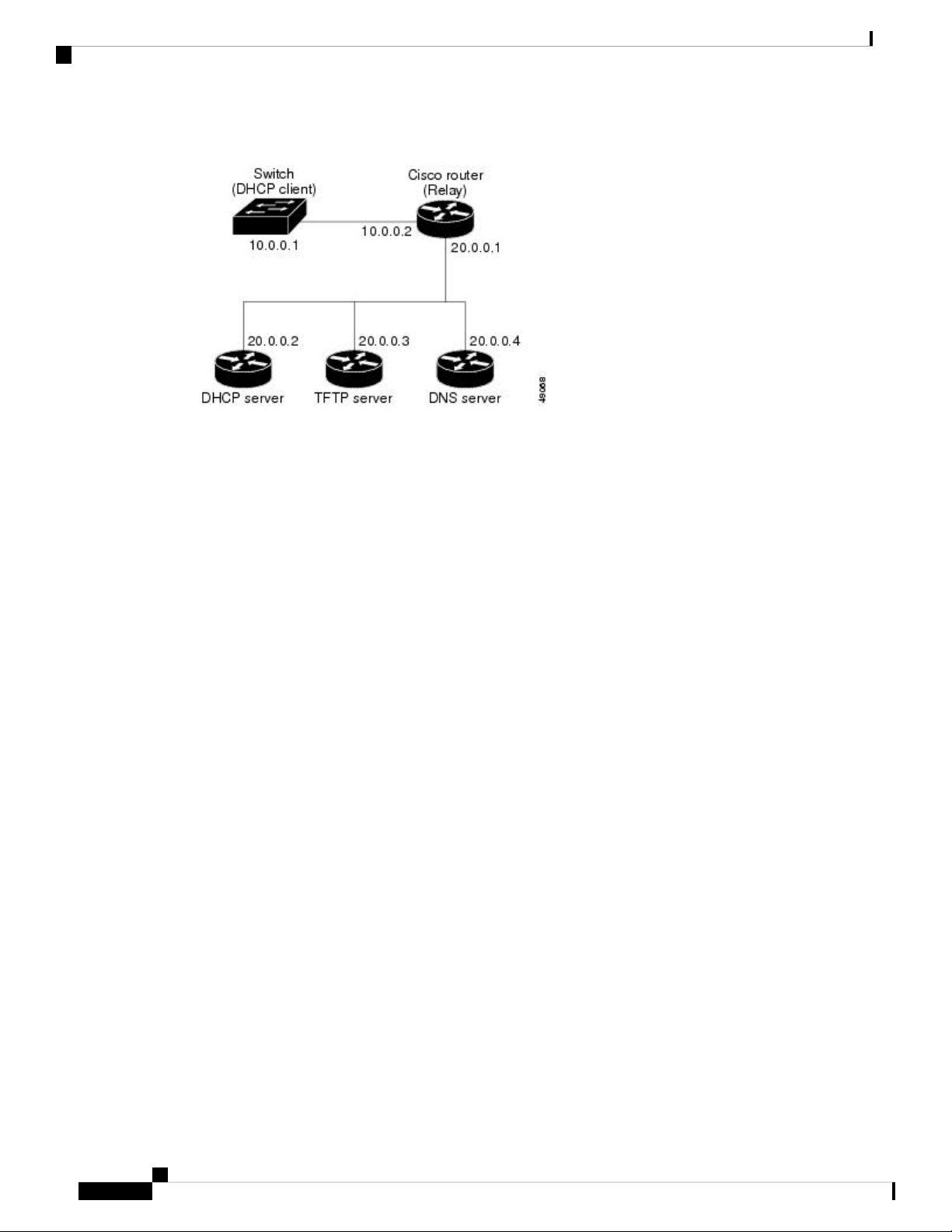
How to Obtain Configuration Files
Figure 2: Relay Device Used in Autoconfiguration
How to Obtain Configuration Files
Depending on the availability of the IP address and the configuration filename in the DHCP reserved lease,
the switch obtains its configuration information in these ways:
Assigning the Switch IP Address and Default Gateway
• The IP address and the configuration filename is reserved for the switch and provided in the DHCP reply
(one-file read method).
The switch receives its IP address, subnet mask, TFTP server address, and the configuration filename
from the DHCP server. The switch sends a unicast message to the TFTP server to retrieve the named
configuration file from the base directory of the server and upon receipt, it completes its boot up process.
• The IP address and the configuration filename is reserved for the switch, but the TFTP server address is
not provided in the DHCP reply (one-file read method).
The switch receives its IP address, subnet mask, and the configuration filename from the DHCP server.
The switch sends a broadcast message to a TFTP server to retrieve the named configuration file from
the base directory of the server, and upon receipt, it completes its boot-up process.
• Only the IP address is reserved for the switch and provided in the DHCP reply. The configuration filename
is not provided (two-file read method).
The switch receives its IP address, subnet mask, and the TFTP server address from the DHCP server.
The switch sends a unicast message to the TFTP server to retrieve the network-confg or cisconet.cfg
default configuration file. (If the network-confg file cannot be read, the switch reads the cisconet.cfg
file.)
The default configuration file contains the hostnames-to-IP-address mapping for the switch. The switch
fills its host table with the information in the file and obtains its hostname. If the hostname is not found
in the file, the switch uses the hostname in the DHCP reply. If the hostname is not specified in the DHCP
reply, the switch uses the default Switch as its hostname.
After obtaining its hostname from the default configuration file or the DHCP reply, the switch reads the
configuration file that has the same name as its hostname (hostname-confg or hostname.cfg, depending
on whether network-confg or cisconet.cfg was read earlier) from the TFTP server. If the cisconet.cfg file
is read, the filename of the host is truncated to eight characters.
If the switch cannot read the network-confg, cisconet.cfg, or the hostname file, it reads the router-confg
file. If the switch cannot read the router-confg file, it reads the ciscortr.cfg file.
Software Configuration Guide, Cisco IOS Release 15.2(4)E (Catalyst 2960-Plus and 2960-C Switches)
20
Page 79
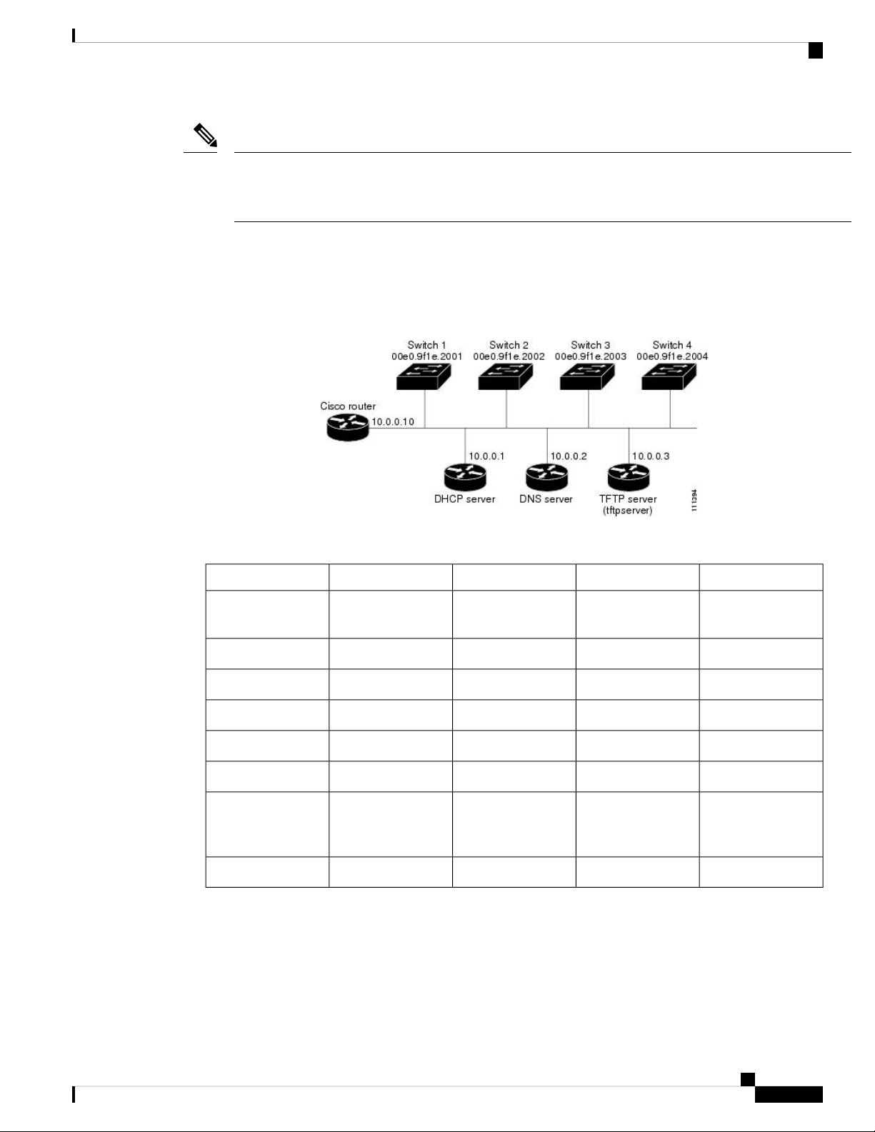
Assigning the Switch IP Address and Default Gateway
Example of DHCP-Based Autoconfiguration Network
Note
The switch broadcasts TFTP server requests if the TFTP server is not obtained from the DHCP replies, if all
attempts to read the configuration file through unicast transmissions fail, or if the TFTP server name cannot
be resolved to an IP address.
Example of DHCP-Based Autoconfiguration Network
A sample network for retrieving IP information using DHCP-based autoconfiguration.
Figure 3: DHCP-Based Autoconfiguration Network
Table 5: DHCP Server Configuration
Switch DSwitch CSwitch BSwitch A
00e0.9f1e.200400e0.9f1e.200300e0.9f1e.200200e0.9f1e.2001Binding key
(hardware address)
10.0.0.2410.0.0.2310.0.0.2210.0.0.21IP address
255.255.255.0255.255.255.0255.255.255.0255.255.255.0Subnet mask
10.0.0.1010.0.0.1010.0.0.1010.0.0.10Router address
10.0.0.210.0.0.210.0.0.210.0.0.2DNS server address
tftpserver or 10.0.0.3tftpserver or 10.0.0.3tftpserver or 10.0.0.3tftpserver or 10.0.0.3TFTP server name
switchd-confgswitchc-confgswitchb-confgswitcha-confgBoot filename
(configuration file)
(optional)
switchdswitchcswitchbswitchaHostname (optional)
Switch A reads its configuration file as follows:
• It obtains its IP address 10.0.0.21 from the DHCP server.
• If no configuration filename is given in the DHCP server reply, Switch A reads the network-confg file
from the base directory of the TFTP server.
• It adds the contents of the network-confg file to its host table.
Software Configuration Guide, Cisco IOS Release 15.2(4)E (Catalyst 2960-Plus and 2960-C Switches)
21
Page 80

Configuring the DHCP Auto Configuration and Image Update Features
• It reads its host table by indexing its IP address 10.0.0.21 to its hostname (switcha).
• It reads the configuration file that corresponds to its hostname; for example, it reads switch1-confg from
the TFTP server.
Switches B through D retrieve their configuration files and IP addresses in the same way.
DNS Server Configuration
The DNS server maps the TFTP server name tftpserver to IP address 10.0.0.3.
TFTP Server Configuration (on UNIX)
The TFTP server base directory is set to /tftpserver/work/. This directory contains the network-confg file used
in the two-file read method. This file contains the hostname to be assigned to the switch based on its IP address.
The base directory also contains a configuration file for each switch (switcha-confg, switchb-confg, and so
forth) as shown in this display:
prompt> cd /tftpserver/work/
prompt> 1s
network-confg
switcha-confg
switchb-confg
switchc-confg
switchd-confg
prompt> cat network-confg
ip host switcha 10.0.0.21
ip host switchb 10.0.0.22
ip host switchc 10.0.0.23
ip host switchd 10.0.0.24
Assigning the Switch IP Address and Default Gateway
DHCP Client Configuration
No configuration file is present on Switch A through Switch D.
Configuration Explanation
In the figure, DHCP-based autoconfiguration network, the Switch A reads its configuration file as follows:
• It obtains its IP address 10.0.0.21 from the DHCP server.
• If no configuration filename is given in the DHCP server reply, Switch A reads the network-confg file
from the base directory of the TFTP server.
• It adds the contents of the network-confg file to its host table.
• It reads its host table by indexing its IP address 10.0.0.21 to its hostname (switcha).
• It reads the configuration file that corresponds to its hostname; for example, it reads switch1-confg from
the TFTP server.
Switches B through D retrieve their configuration files and IP addresses in the same way.
Configuring the DHCP Auto Configuration and Image Update Features
Using DHCP to download a new image and a new configuration to a switch requires that you configure at
least two switches: One switch acts as a DHCP and TFTP server. The client switch is configured to download
either a new configuration file or a new configuration file and a new image file.
Software Configuration Guide, Cisco IOS Release 15.2(4)E (Catalyst 2960-Plus and 2960-C Switches)
22
Page 81

Assigning the Switch IP Address and Default Gateway
Configuring DHCP Autoconfiguration (Only Configuration File)
Configuring DHCP Autoconfiguration (Only Configuration File)
This task describes how to configure DHCP autoconfiguration of the TFTP and DHCP settings on an existing
switch in the network so that it can support the autoconfiguration of a new switch.
SUMMARY STEPS
1. configure terminal
2. ip dhcp pool poolname
3. boot filename
4. network network-number mask prefix-length
5. default-router address
6. option 150 address
7. exit
8. tftp-server flash:filename.text
9. interface interface-id
10. no switchport
11. ip address address mask
12. end
DETAILED STEPS
Step 1
Example:
Switch# configure terminal
Step 2
ip dhcp pool poolname
Example:
Switch(config)# ip dhcp pool pool
Step 3
boot filename
Example:
Switch(dhcp-config)# boot config-boot.text
Step 4
network network-number mask prefix-length
Example:
Switch(dhcp-config)# network 10.10.10.0
255.255.255.0
PurposeCommand or Action
Enters global configuration mode.configure terminal
Creates a name for the DHCP server address pool, and
enters DHCP pool configuration mode.
Specifies the name of the configuration file that is used as
a boot image.
Specifies the subnet network number and mask of the
DHCP address pool.
Note
The prefix length specifies the number of bits
that comprise the address prefix. The prefix is
an alternative way of specifying the network
mask of the client. The prefix length must be
preceded by a forward slash (/).
Software Configuration Guide, Cisco IOS Release 15.2(4)E (Catalyst 2960-Plus and 2960-C Switches)
23
Page 82

Configuring DHCP Autoconfiguration (Only Configuration File)
Assigning the Switch IP Address and Default Gateway
PurposeCommand or Action
Step 5
Step 6
Step 7
Step 8
default-router address
Example:
Switch(dhcp-config)# default-router 10.10.10.1
Example:
Switch(dhcp-config)# option 150 10.10.10.1
Example:
Switch(dhcp-config)# exit
Example:
Switch(config)# tftp-server flash:config-boot.text
Specifies the IP address of the default router for a DHCP
client.
Specifies the IP address of the TFTP server.option 150 address
Returns to global configuration mode.exit
Specifies the configuration file on the TFTP server.tftp-server flash:filename.text
Step 9
Step 10
Step 11
Step 12
interface interface-id
Example:
Example:
Switch(config-if)# no switchport
Example:
Switch(config-if)# ip address 10.10.10.1
255.255.255.0
Example:
Switch(config-if)# end
Specifies the address of the client that will receive the
configuration file.
Puts the interface into Layer 3 mode.no switchport
Specifies the IP address and mask for the interface.ip address address mask
Returns to privileged EXEC mode.end
Software Configuration Guide, Cisco IOS Release 15.2(4)E (Catalyst 2960-Plus and 2960-C Switches)
24
Page 83

Assigning the Switch IP Address and Default Gateway
Configuring DHCP Auto-Image Update (Configuration File and Image)
Configuring DHCP Auto-Image Update (Configuration File and Image)
This task describes DHCP autoconfiguration to configure TFTP and DHCP settings on an existing switch to
support the installation of a new switch.
Before you begin
You must first create a text file (for example, autoinstall_dhcp) that will be uploaded to the switch. In the text
file, put the name of the image that you want to download (for example,
c3750e-ipservices-mz.122-44.3.SE.tarc3750x-ipservices-mz.122-53.3.SE2.tar). This image must be a tar and
not a bin file.
SUMMARY STEPS
1. configure terminal
2. ip dhcp pool poolname
3. boot filename
4. network network-number mask prefix-length
5. default-router address
6. option 150 address
7. option 125 hex
8. copy tftp flash filename.txt
9. copy tftp flash imagename.bin
10. exit
11. tftp-server flash: config.text
12. tftp-server flash: imagename.bin
13. tftp-server flash: filename.txt
14. interface interface-id
15. no switchport
16. ip address address mask
17. end
18. copy running-config startup-config
DETAILED STEPS
Step 1
Example:
Switch# configure terminal
Step 2
ip dhcp pool poolname
Example:
Switch(config)# ip dhcp pool pool1
PurposeCommand or Action
Enters global configuration mode.configure terminal
Creates a name for the DHCP server address pool and enter
DHCP pool configuration mode.
Software Configuration Guide, Cisco IOS Release 15.2(4)E (Catalyst 2960-Plus and 2960-C Switches)
25
Page 84

Configuring DHCP Auto-Image Update (Configuration File and Image)
Assigning the Switch IP Address and Default Gateway
PurposeCommand or Action
Step 3
Step 4
Step 5
Step 6
Example:
Switch(dhcp-config)# boot config-boot.text
network network-number mask prefix-length
Example:
Switch(dhcp-config)# network 10.10.10.0
255.255.255.0
default-router address
Example:
Switch(dhcp-config)# default-router 10.10.10.1
Example:
Specifies the name of the file that is used as a boot image.boot filename
Specifies the subnet network number and mask of the
DHCP address pool.
Note
The prefix length specifies the number of bits
that comprise the address prefix. The prefix is
an alternative way of specifying the network
mask of the client. The prefix length must be
preceded by a forward slash (/).
Specifies the IP address of the default router for a DHCP
client.
Specifies the IP address of the TFTP server.option 150 address
Step 7
Step 8
Step 9
Step 10
Switch(dhcp-config)# option 150 10.10.10.1
option 125 hex
Example:
Switch(dhcp-config)# option 125 hex
0000.0009.0a05.08661.7574.6f69.6e73.7461.6c6c.5f64.686370
Example:
Switch(config)# copy tftp flash image.bin
Example:
Switch(config)# copy tftp flash image.bin
Example:
Specifies the path to the text file that describes the path to
the image file.
Uploads the text file to the switch.copy tftp flash filename.txt
Uploads the tar file for the new image to the switch.copy tftp flash imagename.bin
Returns to global configuration mode.exit
Software Configuration Guide, Cisco IOS Release 15.2(4)E (Catalyst 2960-Plus and 2960-C Switches)
26
Page 85

Assigning the Switch IP Address and Default Gateway
Switch(dhcp-config)# exit
Configuring DHCP Auto-Image Update (Configuration File and Image)
PurposeCommand or Action
Step 11
Step 12
Step 13
Step 14
tftp-server flash: config.text
Example:
Switch(config)# tftp-server flash:config-boot.text
Example:
Switch(config)# tftp-server flash:image.bin
tftp-server flash: filename.txt
Example:
Switch(config)# tftp-server flash:boot-config.text
interface interface-id
Example:
Switch(config)# interface gigabitethernet 1/0/4
Specifies the Cisco IOS configuration file on the TFTP
server.
Specifies the image name on the TFTP server.tftp-server flash: imagename.bin
Specifies the text file that contains the name of the image
file to download
Specifies the address of the client that will receive the
configuration file.
Step 15
Step 16
Step 17
Puts the interface into Layer 3 mode.no switchport
Example:
Switch(config-if)# no switchport
Specifies the IP address and mask for the interface.ip address address mask
Example:
Switch(config-if)# ip address 10.10.10.1
255.255.255.0
Returns to privileged EXEC mode.end
Example:
Switch(config-if)# end
Software Configuration Guide, Cisco IOS Release 15.2(4)E (Catalyst 2960-Plus and 2960-C Switches)
27
Page 86

Configuring the Client to Download Files from DHCP Server
Assigning the Switch IP Address and Default Gateway
PurposeCommand or Action
Step 18
(Optional) Saves your entries in the configuration file.copy running-config startup-config
Example:
Switch(config-if)# end
Configuring the Client to Download Files from DHCP Server
Note
You should only configure and enable the Layer 3 interface. Do not assign an IP address or DHCP-based
autoconfiguration with a saved configuration.
SUMMARY STEPS
1. configure terminal
2. boot host dhcp
3. boot host retry timeout timeout-value
4. banner config-save ^C warning-message ^C
5. end
6. show boot
DETAILED STEPS
Step 1
Example:
Switch# configure terminal
Step 2
Example:
Switch(conf)# boot host dhcp
Step 3
boot host retry timeout timeout-value
Example:
Switch(conf)# boot host retry timeout 300
Step 4
banner config-save ^C warning-message ^C
Example:
PurposeCommand or Action
Enters global configuration mode.configure terminal
Enables autoconfiguration with a saved configuration.boot host dhcp
(Optional) Sets the amount of time the system tries to
download a configuration file.
Note
If you do not set a timeout, the system will try
indefinitely to obtain an IP address from the
DHCP server.
(Optional) Creates warning messages to be displayed when
you try to save the configuration file to NVRAM.
Software Configuration Guide, Cisco IOS Release 15.2(4)E (Catalyst 2960-Plus and 2960-C Switches)
28
Page 87

Assigning the Switch IP Address and Default Gateway
Switch(conf)# banner config-save ^C Caution Saving Configuration File
to NVRAM May Cause You to No longer Automatically
Download Configuration Files at Reboot^C
Manually Assigning IP Information to Multiple SVIs
PurposeCommand or Action
Step 5
Returns to privileged EXEC mode.end
Example:
Switch(config-if)# end
Step 6
Verifies the configuration.show boot
Example:
Switch# show boot
Manually Assigning IP Information to Multiple SVIs
This task describes how to manually assign IP information to multiple switched virtual interfaces (SVIs):
SUMMARY STEPS
1. configure terminal
2. interface vlan vlan-id
3. ip address ip-address subnet-mask
4. exit
5. ip default-gateway ip-address
6. end
7. show interfaces vlan vlan-id
8. show ip redirects
DETAILED STEPS
Step 1
Example:
Switch# configure terminal
Step 2
interface vlan vlan-id
Example:
Switch(config)# interface vlan 99
PurposeCommand or Action
Enters global configuration mode.configure terminal
Enters interface configuration mode, and enters the VLAN
to which the IP information is assigned. The range is 1 to
4094.
Software Configuration Guide, Cisco IOS Release 15.2(4)E (Catalyst 2960-Plus and 2960-C Switches)
29
Page 88

Manually Assigning IP Information to Multiple SVIs
Assigning the Switch IP Address and Default Gateway
PurposeCommand or Action
Step 3
Step 4
Step 5
Example:
Switch(config-vlan)# ip address 10.10.10.2
255.255.255.0
Example:
Switch(config-vlan)# exit
ip default-gateway ip-address
Example:
Switch(config)# ip default-gateway 10.10.10.1
Enters the IP address and subnet mask.ip address ip-address subnet-mask
Returns to global configuration mode.exit
Enters the IP address of the next-hop router interface that
is directly connected to the switch where a default gateway
is being configured. The default gateway receives IP packets
with unresolved destination IP addresses from the switch.
Once the default gateway is configured, the switch has
connectivity to the remote networks with which a host needs
to communicate.
Note
When your switch is configured to route with
IP, it does not need to have a default gateway
set.
Step 6
Step 7
Step 8
Example:
Switch(config)# end
Example:
Switch# show interfaces vlan 99
Example:
Switch# show ip redirects
Note
Returns to privileged EXEC mode.end
Verifies the configured IP address.show interfaces vlan vlan-id
Verifies the configured default gateway.show ip redirects
The switch capwap relays on default-gateway
configuration to support routed access point join
the switch.
Software Configuration Guide, Cisco IOS Release 15.2(4)E (Catalyst 2960-Plus and 2960-C Switches)
30
Page 89

Assigning the Switch IP Address and Default Gateway
Checking and Saving the Running Configuration
You can check the configuration settings that you entered or changes that you made by entering this privileged
EXEC command:
Switch# show running-config
Building configuration...
Current configuration: 1363 bytes
!
version 12.2
no service pad
service timestamps debug uptime
service timestamps log uptime
no service password-encryption
!
hostname
!
enable secret 5 $1$ej9.$DMUvAUnZOAmvmgqBEzIxE0
!
.
<output truncated>
.
ip address 172.20.137.50 255.255.255.0
!
mvr type source
<output truncated>
...!
interface VLAN1
ip address 172.20.137.50 255.255.255.0
no ip directed-broadcast
!
ip default-gateway 172.20.137.1 !
!
snmp-server community private RW
snmp-server community public RO
snmp-server community private@es0 RW
snmp-server community public@es0 RO
snmp-server chassis-id 0x12
!
end
Checking and Saving the Running Configuration
To store the configuration or changes you have made to your startup configuration in flash memory, enter
this privileged EXEC command:
Switch# copy running-config startup-config
Destination filename [startup-config]?
Building configuration...
This command saves the configuration settings that you made. If you fail to do this, your configuration will
be lost the next time you reload the system. To display information stored in the NVRAM section of flash
memory, use the show startup-config or more startup-config privileged EXEC command.
For more information about alternative locations from which to copy the configuration file, see "Working
with the Cisco IOS File System, Configuration Files, and Software Images."
Configuring the NVRAM Buffer Size
The default NVRAM buffer size is 512 KB. In some cases, the configuration file might be too large to save
to NVRAM. Typically, this occurs when you have many switches in a switch stack. You can configure the
size of the NVRAM buffer to support larger configuration files. The new NVRAM buffer size is synced to
all current and new member switches.
Software Configuration Guide, Cisco IOS Release 15.2(4)E (Catalyst 2960-Plus and 2960-C Switches)
31
Page 90

Configuring the NVRAM Buffer Size
Note
SUMMARY STEPS
DETAILED STEPS
Assigning the Switch IP Address and Default Gateway
After you configure the NVRAM buffer size, reload the switch or switch stack.
When you add a switch to a stack and the NVRAM size differs, the new switch syncs with the stack and
reloads automatically.
Beginning in privileged EXEC mode, follow these steps to configure the NVRAM buffer size:
1. configure terminal
2. boot buffersizesize
3. end
4. show boot
PurposeCommand or Action
Step 1
Step 2
Step 3
Step 4
boot buffersizesize
show boot
Enter global configuration mode.configure terminal
Configure the NVRAM buffersize in KB. The valid range
for size is from 4096 to 1048576 .
Return to privileged EXEC mode.end
Verify the configuration.
This example shows how to configure the NVRAM buffer
size:
Switch# configure terminal
Enter configuration commands, one per line. End
with CNTL/Z.
Switch(config)# boot buffersize 524288
Switch(config)# end
Switch# show boot
BOOT path-list :
Config file : flash:/config.text
Private Config file : flash:/private-config.text
Enable Break : no
Manual Boot : no
HELPER path-list :
Auto upgrade : yes
Auto upgrade path :
NVRAM/Config file
buffer size: 524288
Timeout for Config
Download: 300 seconds
Config Download
via DHCP: enabled (next boot: enabled)
Switch#
Software Configuration Guide, Cisco IOS Release 15.2(4)E (Catalyst 2960-Plus and 2960-C Switches)
32
Page 91

Assigning the Switch IP Address and Default Gateway
Modifying the Switch Startup Configuration
Default Boot Configuration
Default SettingFeature
Modifying the Switch Startup Configuration
Operating system software
image
Configuration file
The switch attempts to automatically boot up the system using information
in the BOOT environment variable. If the variable is not set, the switch
attempts to load and execute the first executable image it can by performing
a recursive, depth-first search throughout the flash file system.
The Cisco IOS image is stored in a directory that has the same name as the
image file (excluding the .bin extension).
In a depth-first search of a directory, each encountered subdirectory is
completely searched before continuing the search in the original directory.
Configured switches use the config.text file stored on the system board in
flash memory.
A new switch has no configuration file.
Automatically Downloading a Configuration File
You can automatically download a configuration file to your switch by using the DHCP-based autoconfiguration
feature. For more information, see the "Understanding DHCP-Based Autoconfiguration" section.
Specifying the Filename to Read and Write the System Configuration
By default, the Cisco IOS software uses the config.text file to read and write a nonvolatile copy of the system
configuration. However, you can specify a different filename, which will be loaded during the next boot cycle.
SUMMARY STEPS
DETAILED STEPS
Step 1
Example:
Before you begin
Use a standalone switch for this task.
1. configure terminal
2. boot flash:/file-url
3. end
4. show boot
5. copy running-config startup-config
PurposeCommand or Action
Enters global configuration mode.configure terminal
Software Configuration Guide, Cisco IOS Release 15.2(4)E (Catalyst 2960-Plus and 2960-C Switches)
33
Page 92

Manually Booting the Switch
Switch# configure terminal
Assigning the Switch IP Address and Default Gateway
PurposeCommand or Action
Step 2
Step 3
Step 4
Step 5
boot flash:/file-url
Example:
Switch(config)# boot flash:config.text
Example:
Switch(config)# end
Example:
Switch# show boot
Example:
Switch# copy running-config startup-config
Specifies the configuration file to load during the next boot
cycle.
file-url—The path (directory) and the configuration
filename.
Filenames and directory names are case-sensitive.
Returns to privileged EXEC mode.end
Verifies your entries.show boot
The boot global configuration command changes the setting
of the CONFIG_FILE environment variable.
(Optional) Saves your entries in the configuration file.copy running-config startup-config
Manually Booting the Switch
By default, the switch automatically boots up; however, you can configure it to manually boot up.
Before you begin
Use a standalone switch for this task.
SUMMARY STEPS
1. configure terminal
2. boot manual
3. end
4. show boot
5. copy running-config startup-config
DETAILED STEPS
Step 1
Example:
PurposeCommand or Action
Enters global configuration mode.configure terminal
Software Configuration Guide, Cisco IOS Release 15.2(4)E (Catalyst 2960-Plus and 2960-C Switches)
34
Page 93

Assigning the Switch IP Address and Default Gateway
Switch# configure terminal
Booting a Specific Software Image On a Switch
PurposeCommand or Action
Step 2
Step 3
Step 4
boot manual
Example:
Switch(config)# boot manual
Example:
Switch(config)# end
Example:
Switch# show boot
Enables the switch to manually boot up during the next boot
cycle.
Returns to privileged EXEC mode.end
Verifies your entries.show boot
The boot manual global command changes the setting of
the MANUAL_BOOT environment variable.
The next time you reboot the system, the switch is in boot
loader mode, shown by the switch: prompt. To boot up the
system, use the boot filesystem:/file-url boot loader
command.
• filesystem:—Uses flash: for the system board flash
device.
Switch: boot flash:
Step 5
Example:
Switch# copy running-config startup-config
Booting a Specific Software Image On a Switch
By default, the switch attempts to automatically boot up the system using information in the BOOT environment
variable. If this variable is not set, the switch attempts to load and execute the first executable image it can
by performing a recursive, depth-first search throughout the flash file system. In a depth-first search of a
directory, each encountered subdirectory is completely searched before continuing the search in the original
directory. However, you can specify a specific image to boot up.
SUMMARY STEPS
1. configure terminal
• For file-url—Specifies the path (directory) and the
name of the bootable image.
Filenames and directory names are case-sensitive.
(Optional) Saves your entries in the configuration file.copy running-config startup-config
Software Configuration Guide, Cisco IOS Release 15.2(4)E (Catalyst 2960-Plus and 2960-C Switches)
35
Page 94

Controlling Environment Variables
DETAILED STEPS
Assigning the Switch IP Address and Default Gateway
2. end
3. show boot system
4. copy running-config startup-config
PurposeCommand or Action
Step 1
Step 2
Step 3
Step 4
Example:
Switch# configure terminal
Example:
Switch(config)# end
Example:
Switch# show boot system
Example:
Switch# copy running-config startup-config
Enters global configuration mode.configure terminal
Returns to privileged EXEC mode.end
Verifies your entries.show boot system
The boot system global command changes the setting of
the BOOT environment variable.
During the next boot cycle, the switch attempts to
automatically boot up the system using information in the
BOOT environment variable.
(Optional) Saves your entries in the configuration file.copy running-config startup-config
Controlling Environment Variables
With a normally operating switch, you enter the boot loader mode only through a switch console connection
configured for 9600 b/s. Unplug the switch power cord, and press the switch Mode button while reconnecting
the power cord. You can release the Mode button a second or two after the LED above port 1 turns off. Then
the boot loader switch: prompt appears.
The switch boot loader software provides support for nonvolatile environment variables, which can be used
to control how the boot loader, or any other software running on the system, behaves. Boot loader environment
variables are similar to environment variables that can be set on UNIX or DOS systems.
Environment variables that have values are stored in flash memory outside of the flash file system.
Each line in these files contains an environment variable name and an equal sign followed by the value of the
variable. A variable has no value if it is not listed in this file; it has a value if it is listed in the file even if the
value is a null string. A variable that is set to a null string (for example, " ") is a variable with a value. Many
environment variables are predefined and have default values.
Environment variables store two kinds of data:
Software Configuration Guide, Cisco IOS Release 15.2(4)E (Catalyst 2960-Plus and 2960-C Switches)
36
Page 95

Assigning the Switch IP Address and Default Gateway
• Data that controls code, which does not read the Cisco IOS configuration file. For example, the name of
a boot loader helper file, which extends or patches the functionality of the boot loader can be stored as
an environment variable.
• Data that controls code, which is responsible for reading the Cisco IOS configuration file. For example,
the name of the Cisco IOS configuration file can be stored as an environment variable.
You can change the settings of the environment variables by accessing the boot loader or by using Cisco IOS
commands. Under normal circumstances, it is not necessary to alter the setting of the environment variables.
Note
For complete syntax and usage information for the boot loader commands and environment variables, see the
command reference for this release.
Table 6: Environment Variables
Controlling Environment Variables
BOOT
MANUAL_BOOT
Boot Loader CommandVariable
set BOOTfilesystem :/ file-url...
A semicolon-separated list of
executable files to try to load and
execute when automatically
booting. If the BOOT
environment variable is not set,
the system attempts to load and
execute the first executable image
it can find by using a recursive,
depth-first search through the
flash file system. If the BOOT
variable is set but the specified
images cannot be loaded, the
system attempts to boot the first
bootable file that it can find in the
flash file system.
set MANUAL_BOOT yes
Decides whether the switch
automatically or manually boots
up.
Valid values are 1, yes, 0, and no.
If it is set to no or 0, the boot
loader attempts to automatically
boot up the system. If it is set to
anything else, you must manually
boot up the switch from the boot
loader mode.
Cisco IOS Global Configuration
Command
boot systemfilesystem:/file-url ...
Specifies the Cisco IOS image to
load during the next boot cycle.
This command changes the setting
of the BOOT environment variable
boot manual
Enables manually booting up the
switch during the next boot cycle
and changes the setting of the
MANUAL_BOOT environment
variable.
The next time you reboot the
system, the switch is in boot loader
mode. To boot up the system, use
the boot flash: filesystem :/ file-url
boot loader command, and specify
the name of the bootable image.
Software Configuration Guide, Cisco IOS Release 15.2(4)E (Catalyst 2960-Plus and 2960-C Switches)
37
Page 96

Scheduling a Reload of the Software Image
Assigning the Switch IP Address and Default Gateway
CONFIG_FILE
Scheduling a Reload of the Software Image
You can schedule a reload of the software image to occur on the switch at a later time (for example, late at
night or during the weekend when the switch is used less), or you can synchronize a reload network-wide (for
example, to perform a software upgrade on all switches in the network).
Note
A scheduled reload must take place within approximately 24 days.
Configuring a Scheduled Reload
To configure your switch to reload the software image at a later time, use one of these commands in privileged
EXEC mode:
Boot Loader CommandVariable
set CONFIG_FILE flash: /
file-url
Cisco IOS Global Configuration
Command
boot config-file flash:/ file-url
Specifies the filename that Cisco
IOS uses to read and write a
nonvolatile copy of the system
configuration. This command
changes the CONFIG_FILE
environment variable.
• reload in[hh :]mm [text]
This command schedules a reload of the software to take affect in the specified minutes or hours and
minutes. The reload must take place within approximately 24 days. You can specify the reason for the
reload in a string up to 255 characters in length.
• reload athh:mm [month dayIday month [text]
This command schedules a reload of the software to take place at the specified time (using a 24-hour
clock). If you specify the month and day, the reload is scheduled to take place at the specified time and
date. If you do not specify the month and day, the reload takes place at the specified time on the current
day (if the specified time is later than the current time) or on the next day (if the specified time is earlier
than the current time). Specifying 00:00 schedules the reload for midnight.
Note
Use the at keyword only if the switch system clock has been set (through Network
Time Protocol (NTP), the hardware calendar, or manually). The time is relative
to the configured time zone on the switch. To schedule reloads across several
switches to occur simultaneously, the time on each switch must be synchronized
with NTP.
The reload command halts the system. If the system is not set to manually boot up, it reboots itself. Use
the reload command after you save the switch configuration information to the startup configuration
(copy running-config startup-config).
Software Configuration Guide, Cisco IOS Release 15.2(4)E (Catalyst 2960-Plus and 2960-C Switches)
38
Page 97

Assigning the Switch IP Address and Default Gateway
If your switch is configured for manual booting, do not reload it from a virtual terminal. This restriction
prevents the switch from entering the boot loader mode and thereby taking it from the remote user's
control.
If you modify your configuration file, the switch prompts you to save the configuration before reloading.
During the save operation, the system requests whether you want to proceed with the save if the CONFIG_FILE
environment variable points to a startup configuration file that no longer exists. If you proceed in this situation,
the system enters setup mode upon reload.
This example shows how to reload the software on the switch on the current day at 7:30 p.m:
Switch# reload at 19:30
Reload scheduled for 19:30:00 UTC Wed Jun 5 1996 (in 2 hours and 25 minutes)
Proceed with reload? [confirm]
This example shows how to reload the software on the switch at a future time:
Switch# reload at 02:00 jun 20
Reload scheduled for 02:00:00 UTC Thu Jun 20 1996 (in 344 hours and 53 minutes)
Proceed with reload? [confirm]
To cancel a previously scheduled reload, use the reload cancel privileged EXEC command
Boot Loader Upgrade and Image Verification for the FIPS Mode of Operation
Displaying Scheduled Reload Information
To display information about a previously scheduled reload or to find out if a reload has been scheduled on
the switch, use the show reload privileged EXEC command.
It displays reload information including the time the reload is scheduled to occur and the reason for the reload
(if it was specified when the reload was scheduled).
Boot Loader Upgrade and Image Verification for the FIPS Mode of Operation
To operate in the FIPS mode, complete these steps:
• Enable the FIPS mode on the switch.To enable the FIPS mode, enter the fips authorization-key
authorization-key global configuration command. To disable the FIPS mode, use the no version of the
command.
• Use signed and validated images. Cisco IOS Release 15.2(1)E supports an updated boot loader that can
validate the Cisco IOS image signature only in the FIPS mode of operation.
Note
Ensure that the power is not turned off while updating the boot loader. If the power is turned off during the
update, you will have to replace the switch by using a Return Merchandise Authorization (RMA) license.
Table 4-6 describes upgrade and downgrade scenarios using different images and using the FIPS mode or
non-FIPS mode:
Software Configuration Guide, Cisco IOS Release 15.2(4)E (Catalyst 2960-Plus and 2960-C Switches)
39
Page 98

Boot Loader Upgrade and Image Verification for the FIPS Mode of Operation
Table 7: Upgrade and Downgrade Scenarios Relating to FIPS Certified Images
Assigning the Switch IP Address and Default Gateway
Status or ResultActionUpgrade/ Downgrade Scenario
Upgrade from an image that is in
the FIPS mode to a Cisco IOS
Release 15.2(1)E image in the FIPS
mode.
Upgrade from a switch that is in the
non-FIPS mode to a Cisco IOS
Release 15.2(1)E image in the FIPS
mode
Boot with the Cisco IOS Release
15.2(1)E image.
• Configure the fips
authorization- key
authorization-key global
configuration command
• Reload the switch for the FIPS
key to be operational. By
default, the switch
automatically boots up;
however, if you have
configured it to boot up
manually, you have to initiate
the reboot.
• After the boot loader is
upgraded, boot with the Cisco
IOS Release 15.2(1)E image.
• The boot loader is upgraded.
• The image signature is
verified.
• The following message
appears in the boot sequence:
“Image passed digital
signature verification.”
Note
If you upload a corrupt
or unsigned image, the
following message
appears during boot up:
“Image verification
failed.”
• The boot loader is upgraded.
• The image signature is
verified.
Note
If you upload a corrupt
or unsigned image, the
following message
appears during boot up:
“Image verification
failed.
Upgrade to Cisco IOS Release
15.2(1)E in the non-FIPS mode
Boot with the Cisco IOS Release
15.2(1)E image.
• The boot loader is not
updated.
• The image signature is not
verified
• The switch works normally.
Software Configuration Guide, Cisco IOS Release 15.2(4)E (Catalyst 2960-Plus and 2960-C Switches)
40
Page 99

Assigning the Switch IP Address and Default Gateway
Boot Loader Upgrade and Image Verification for the FIPS Mode of Operation
Status or ResultActionUpgrade/ Downgrade Scenario
Configure an existing FIPS
complaint switch running Cisco
IOS Release 15.2(1)E to work in a
non-FIPS mode.
Downgrade from a Cisco IOS
Release 15.2(1)E image in FIPS
mode to an older release.
• Configure the no fips
authorization- key
authorization-key global
configuration command.
• Reload the switch for the
configuration to take effect.
By default, the switch
automatically boots up;
however, if you have
configured it to boot up
manually, you have to initiate
the reboot.
• Configure the no fips
authorization- key
authorization-key global
configuration command
• Reload the switch for the
configuration to take effect.
By default, the switch
automatically boots up;
however, if you have
configured it to boot up
manually, you have to initiate
reboot.
• Upload and boot the older
image.
• The boot loader is not
updated.
• The switch works normally
and the FIPS commands are
no longer available.
• The following message
appears in the boot sequence:
“Image passed digital
signature verification”.
Note
If you upload a corrupt
or unsigned image, the
following message
appears during boot up:
“WARNING: Unable to
determine image
authentication. Image is
either unsigned or is
signed but corrupted.”
• The boot loader is not
downgraded
• The switch work normally and
the FIPS commands are no
longer available.
• The following message
appears in the boot sequence:
“WARNING: Unable to
determine image
authentication. Image is either
unsigned or is signed but
corrupted.”
Software Configuration Guide, Cisco IOS Release 15.2(4)E (Catalyst 2960-Plus and 2960-C Switches)
41
Page 100

Boot Loader Upgrade and Image Verification for the FIPS Mode of Operation
Assigning the Switch IP Address and Default Gateway
Software Configuration Guide, Cisco IOS Release 15.2(4)E (Catalyst 2960-Plus and 2960-C Switches)
42
 Loading...