

Page 1

Installation and Operation Manual
IPmux-1, IPmux-1E
TDMoIP Gateways
Page 2

Page 3

IPmux-1, IPmux-1E
TDMoIP Gateways
Installation and Operation Manual
Notice
This manual contains information that is proprietary to RAD Data Communications Ltd. ("RAD"). No
part of this publication may be reproduced in any form whatsoever without prior written approval by
RAD Data Communications.
Right, title and interest, all information, copyrights, patents, know-how, trade secrets and other
intellectual property or other proprietary rights relating to this manual and to the IPmux-1, IPmux-1E
and any software components contained therein are proprietary products of RAD protected under
international copyright law and shall be and remain solely with RAD.
IPmux-1, IPmux-1E is a registered trademark of RAD. No right, license, or interest to such trademark is
granted hereunder, and you agree that no such right, license, or interest shall be asserted by you with
respect to such trademark.
You shall not copy, reverse compile or reverse assemble all or any portion of the Manual or the IPmux1, IPmux-1E. You are prohibited from, and shall not, directly or indirectly, develop, market, distribute,
license, or sell any product that supports substantially similar functionality as the IPmux-1, IPmux-1E,
based on or derived in any way from the IPmux-1, IPmux-1E. Your undertaking in this paragraph shall
survive the termination of this Agreement.
This Agreement is effective upon your opening of the IPmux-1, IPmux-1E package and shall continue
until terminated. RAD may terminate this Agreement upon the breach by you of any term hereof.
Upon such termination by RAD, you agree to return to RAD the IPmux-1, IPmux-1E and all copies and
portions thereof.
For further information contact RAD at the address below or contact your local distributor.
International Headquarters
RAD Data Communications Ltd.
24 Raoul Wallenberg St.
Tel Aviv 69719 Israel
Tel: 972-3-6458181
Fax: 972-3-6498250
E-mail: rad@rad.com
© 1999-2003 RAD Data Communications Ltd. Publication No. 114-200-06/03
U.S. Headquarters
RAD Data Communications Inc.
900 Corporate Drive
Mahwah, NJ 07430 USA
Tel: (201) 529-1100, Toll free: 1-800-444-7234
Fax: (201) 529-5777
E-mail: market@radusa.com
Page 4

Limited Warranty
RAD warrants to DISTRIBUTOR that the hardware in the IPmux-1, IPmux-1E to be delivered
hereunder shall be free of defects in material and workmanship under normal use and service for a
period of twelve (12) months following the date of shipment to DISTRIBUTOR.
If, during the warranty period, any component part of the equipment becomes defective by reason of
material or workmanship, and DISTRIBUTOR immediately notifies RAD of such defect, RAD shall have
the option to choose the appropriate corrective action: a) supply a replacement part, or b) request
return of equipment to its plant for repair, or c) perform necessary repair at the equipment's location.
In the event that RAD requests the return of equipment, each party shall pay one-way shipping costs.
RAD shall be released from all obligations under its warranty in the event that the equipment has been
subjected to misuse, neglect, accident or improper installation, or if repairs or modifications were
made by persons other than RAD's own authorized service personnel, unless such repairs by others
were made with the written consent of RAD.
The above warranty is in lieu of all other warranties, expressed or implied. There are no warranties
which extend beyond the face hereof, including, but not limited to, warranties of merchantability and
fitness for a particular purpose, and in no event shall RAD be liable for consequential damages.
RAD shall not be liable to any person for any special or indirect damages, including, but not limited to,
lost profits from any cause whatsoever arising from or in any way connected with the manufacture,
sale, handling, repair, maintenance or use of the IPmux-1, IPmux-1E, and in no event shall RAD's
liability exceed the purchase price of the IPmux-1, IPmux-1E.
DISTRIBUTOR shall be responsible to its customers for any and all warranties which it makes relating
to IPmux-1, IPmux-1E and for ensuring that replacements and other adjustments required in
connection with the said warranties are satisfactory.
Software components in the IPmux-1, IPmux-1E are provided "as is" and without warranty of any kind.
RAD disclaims all warranties including the implied warranties of merchantability and fitness for a
particular purpose. RAD shall not be liable for any loss of use, interruption of business or indirect,
special, incidental or consequential damages of any kind. In spite of the above RAD shall do its best to
provide error-free software products and shall offer free Software updates during the warranty period
under this Agreement.
RAD's cumulative liability to you or any other party for any loss or damages resulting from any claims,
demands, or actions arising out of or relating to this Agreement and the IPmux-1, IPmux-1E shall not
exceed the sum paid to RAD for the purchase of the IPmux-1, IPmux-1E. In no event shall RAD be liable
for any indirect, incidental, consequential, special, or exemplary damages or lost profits, even if RAD has
been advised of the possibility of such damages.
This Agreement shall be construed and governed in accordance with the laws of the State of Israel.
Page 5

General Safety Instructions
The following instructions serve as a general guide for the safe installation and operation of
telecommunications products. Additional instructions, if applicable, are included inside the manual.
Safety Symbols
This symbol may appear on the equipment or in the text. It indicates
potential safety hazards regarding product operation or maintenance to
operator or service personnel.
Warning
Danger of electric shock! Avoid any contact with the marked surface while
the product is energized or connected to outdoor telecommunication lines.
.
Warning
Protective earth: the marked lug or terminal should be connected to the building
protective earth bus.
Some products may be equipped with a laser diode. In such cases, a label
with the laser class and other warnings as applicable will be attached near
the optical transmitter. The laser warning symbol may be also attached.
Please observe the following precautions:
• Before turning on the equipment, make sure that the fiber optic cable is
intact and is connected to the transmitter.
• Do not attempt to adjust the laser drive current.
• Do not use broken or unterminated fiber-optic cables/connectors or look
straight at the laser beam.
• The use of optical devices with the equipment will increase eye hazard.
• Use of controls, adjustments or performing procedures other than those
specified herein, may result in hazardous radiation exposure.
ATTENTION: The laser beam may be invisible!
Always observe standard safety precautions during installation, operation and maintenance of this
product. Only qualified and authorized service personnel should carry out adjustment, maintenance or
repairs to this product. No installation, adjustment, maintenance or repairs should be performed by
either the operator or the user.
Page 6

Handling Energized Products
General Safety Practices
Do not touch or tamper with the power supply when the power cord is connected. Line voltages may
be present inside certain products even when the power switch (if installed) is in the OFF position or a
fuse is blown. For DC-powered products, although the voltages levels are usually not hazardous,
energy hazards may still exist.
Before working on equipment connected to power lines or telecommunication lines, remove jewelry
or any other metallic object that may come into contact with energized parts.
Unless otherwise specified, all products are intended to be grounded during normal use. Grounding is
provided by connecting the mains plug to a wall socket with a protective earth terminal. If an earth lug
is provided on the product, it should be connected to the protective earth at all times, by a wire with a
diameter of 18 AWG or wider. Rack-mounted equipment should be mounted only in earthed racks
and cabinets.
Always make the ground connection first and disconnect it last. Do not connect telecommunication
cables to ungrounded equipment. Make sure that all other cables are disconnected before
disconnecting the ground.
Connection of AC Mains
Make sure that the electrical installation complies with local codes.
Always connect the AC plug to a wall socket with a protective ground.
The maximum permissible current capability of the branch distribution circuit that supplies power to
the product is 16A. The circuit breaker in the building installation should have high breaking capacity
and must operate at short-circuit current exceeding 35A.
Always connect the power cord first to the equipment and then to the wall socket. If a power switch is
provided in the equipment, set it to the OFF position. If the power cord cannot be readily
disconnected in case of emergency, make sure that a readily accessible circuit breaker or emergency
switch is installed in the building installation.
Connection of DC Mains
Unless otherwise specified in the manual, the DC input to the equipment is floating in reference to the
ground. Any single pole can be externally grounded.
Due to the high current capability of DC mains systems, care should be taken when connecting the DC
supply to avoid short-circuits and fire hazards.
DC units should be installed in a restricted access area, i.e. an area where access is authorized only to
qualified service and maintenance personnel.
Make sure that the DC supply is electrically isolated from any AC source and that the installation
complies with the local codes.
The maximum permissible current capability of the branch distribution circuit that supplies power to
the product is 16A. The circuit breaker in the building installation should have high breaking capacity
and must operate at short-circuit current exceeding 35A.
Before connecting the DC supply wires, ensure that power is removed form the DC circuit. Locate the
circuit breaker of the panel board that services the equipment and switch it to the OFF position. When
connecting the DC supply wires, first connect the ground wire to the corresponding terminal, then the
positive pole and last the negative pole. Switch the circuit breaker back to the ON position.
A readily accessible disconnect device that is suitably rated and approved should be incorporated in
the building installation.
Page 7

Connection of Data and Telecommunications Cables
Data and telecommunication interfaces are classified according to their safety status.
The following table lists the status of several standard interfaces. If the status of a given port differs from
the standard one, a notice will be given in the manual.
Ports Safety Status
V.11, V.28, V.35, V.36, RS-530,
X.21, 10 BaseT, 100 BaseT,
Unbalanced E1, E2, E3, STM, DS-2,
DS-3, S-Interface ISDN, Analog voice
E&M
xDSL (without feeding voltage),
Balanced E1, T1, Sub E1/T1
FXS (Foreign Exchange Subscriber) TNV-2 Telecommunication Network Voltage-2:
FXO (Foreign Exchange Office), xDSL
(with feeding voltage), U-Interface
ISDN
SELV Safety Extra Low Voltage:
Ports which do not present a safety hazard. Usually
up to 30 VAC or 60 VDC.
TNV-1 Telecommunication Network Voltage-1:
Ports whose normal operating voltage is within the
limits of SELV, on which overvoltages from
telecommunications networks are possible.
Ports whose normal operating voltage exceeds the
limits of SELV (usually up to 120 VDC or telephone
ringing voltages), on which overvoltages from
telecommunication networks are not possible. These
ports are not permitted to be directly connected to
external telephone and data lines.
TNV-3 Telecommunication Network Voltage-3:
Ports whose normal operating voltage exceeds the
limits of SELV (usually up to 120 VDC or telephone
ringing voltages), on which overvoltages from
telecommunication networks are possible.
Always connect a given port to a port of the same safety status. If in doubt, seek the assistance of a
qualified safety engineer.
Always make sure that the equipment is grounded before connecting telecommunication cables. Do
not disconnect the ground connection before disconnecting all telecommunications cables.
Some SELV and non-SELV circuits use the same connectors. Use caution when connecting cables.
Extra caution should be exercised during thunderstorms.
When using shielded or coaxial cables, verify that there is a good ground connection at both ends. The
earthing and bonding of the ground connections should comply with the local codes.
The telecommunication wiring in the building may be damaged or present a fire hazard in case of
contact between exposed external wires and the AC power lines. In order to reduce the risk, there are
restrictions on the diameter of wires in the telecom cables, between the equipment and the mating
connectors.
Page 8

Caution
To reduce the risk of fire, use only No. 26 AWG or larger telecommunication line cords.
Attention
Pour réduire les risques s’incendie, utiliser seulement des conducteurs de
télécommunications 26 AWG ou de section supérieure.
Some ports are suitable for connection to intra-building or non-exposed wiring or cabling only. In such
cases, a notice will be given in the installation instructions.
Do not attempt to tamper with any carrier-provided equipment or connection hardware.
Electromagnetic Compatibility (EMC)
The equipment is designed and approved to comply with the electromagnetic regulations of major
regulatory bodies. The following instructions may enhance the performance of the equipment and will
provide better protection against excessive emission and better immunity against disturbances.
A good earth connection is essential. When installing the equipment in a rack, make sure to remove all
traces of paint from the mounting points. Use suitable lock-washers and torque. If an external
grounding lug is provided, connect it to the earth bus using braided wire as short as possible.
The equipment is designed to comply with EMC requirements when connecting it with unshielded
twisted pair (UTP) cables. However, the use of shielded wires is always recommended, especially for
high-rate data. In some cases, when unshielded wires are used, ferrite cores should be installed on
certain cables. In such cases, special instructions are provided in the manual.
Disconnect all wires which are not in permanent use, such as cables used for one-time configuration.
The compliance of the equipment with the regulations for conducted emission on the data lines is
dependent on the cable quality. The emission is tested for UTP with 80 dB longitudinal conversion loss
(LCL).
Unless otherwise specified or described in the manual, TNV-1 and TNV-3 ports provide secondary
protection against surges on the data lines. Primary protectors should be provided in the building
installation.
The equipment is designed to provide adequate protection against electro-static discharge (ESD).
However, it is good working practice to use caution when connecting cables terminated with plastic
connectors (without a grounded metal hood, such as flat cables) to sensitive data lines. Before
connecting such cables, discharge yourself by touching earth ground or wear an ESD preventive wrist
strap.
FCC-15 User Information
This equipment has been tested and found to comply with the limits of the Class A digital device,
pursuant to Part 15 of the FCC rules. These limits are designed to provide reasonable protection
against harmful interference when the equipment is operated in a commercial environment. This
equipment generates, uses and can radiate radio frequency energy and, if not installed and used in
accordance with the Installation and Operation manual, may cause harmful interference to the radio
communications. Operation of this equipment in a residential area is likely to cause harmful
interference in which case the user will be required to correct the interference at his own expense.
Page 9

Canadian Emission Requirements
This Class A digital apparatus meets all the requirements of the Canadian Interference-Causing
Equipment Regulation.
Cet appareil numérique de la classe A respecte toutes les exigences du Règlement sur le matériel
brouilleur du Canada.
Warning per EN 55022 (CISPR-22)
Warning
Avertissement
Achtung
This is a class A product. In a domestic environment, this product may cause
radio interference, in which case the user will be required to take adequate
measures.
Cet appareil est un appareil de Classe A. Dans un environnement résidentiel, cet
appareil peut provoquer des brouillages radioélectriques. Dans ces cas, il peut
être demandé à l’utilisateur de prendre les mesures appropriées.
Dieses ist ein Gerät der Funkstörgrenzwertklasse A. In Wohnbereichen können
bei Betrieb dieses Gerätes Rundfunkströrungen auftreten, in welchen Fällen der
Benutzer für entsprechende Gegenmaßnahmen verantwortlich ist.
Page 10

Declaration of Conformity
Manufacturer's Name: RAD Data Communications Ltd.
Manufacturer's Address: 24 Raoul Wallenberg St.
Tel Aviv 69719
Israel
declares that the product:
Product Name: IPmux-1, IPmux-1E
conforms to the following standard(s) or other normative document(s):
EMC: EN 55022 (1994) Limits and methods of measurement of radio disturbance
characteristics of information technology equipment.
EN 50024 (1998) Information technology equipment –Immunity
characteristics – Limits and methods of measurement.
Safety: EN 60950/A4 (1996) Safety of information technology equipment, including
electrical business equipment.
Supplementary Information:
The products herewith comply with the requirements of the EMC Directive 89/336/EEC and the Low
Voltage Directive 73/23/EEC and the R & TTE directive 99/5/EC for wired equipment. The products
were tested in a typical configuration.
Tel Aviv, March 18, 2001
Haim Karshen
VP Quality
European Contact: RAD Data Communications GmbH, Otto-Hahn-Str. 28-30, 85521
Ottobrunn-Riemerling, Germany
Page 11

Preface
Foreword
This manual describes the technical characteristics, applications, installation and operation of
IPmux-1 and IPmux-1E. In this manual the products will be referred to as IPmux-1/1E.
Manual Organization
This manual is organized as follows:
Chapter 1. Introduction
presents the main features versions, applications, functional description, and lists the
technical specifications of IPmux-1/1E.
Chapter 2. Installation
provides detailed installation and operation instructions for IPmux-1/1E.
Chapter 3. Operation
provides general instructions for getting started, managing IPmux-1/1E by means of terminals
and Telnet hosts, and provides typical configuration procedures.
Chapter 4. Tests and Diagnostics
describes the diagnostic and performance monitoring functions supported by IPmux-1/1E.
Appendix A. Boot Sequence for Downloading Software
provides instructions for the installation of new software releases.
Appendix B. Telnet
details management by Telnet.
Appendix C. SNMP Management
describes the SNMP and IP environments, and provides background information regarding
the handling of management traffic.
Appendix D. TFTP Download Procedures
details management by Telnet.
Appendix E. Parameters and Screens
describes the configuration screens and parameters.
Page 12

Conventions
Note
Caution
Warning
A note draws attention to a general rule for a procedure, or to exceptions to a rule.
A caution warns of possible damage to the equipment if a procedure is not
followed correctly.
A warning alerts to the presence of important operating and maintenance
(servicing) instructions in the literature accompanying the equipment. If these
instructions are not followed exactly, possible bodily injury may occur.
Page 13

Page 14

IPmux-1, IPmux-1E
TDMoIP Gateways
Installation and Operation Manual
Notice
This manual contains information that is proprietary to RAD Data Communications Ltd. ("RAD"). No
part of this publication may be reproduced in any form whatsoever without prior written approval by
RAD Data Communications.
Right, title and interest, all information, copyrights, patents, know-how, trade secrets and other
intellectual property or other proprietary rights relating to this manual and to the IPmux-1, IPmux-1E
and any software components contained therein are proprietary products of RAD protected under
international copyright law and shall be and remain solely with RAD.
IPmux-1, IPmux-1E is a registered trademark of RAD. No right, license, or interest to such trademark is
granted hereunder, and you agree that no such right, license, or interest shall be asserted by you with
respect to such trademark.
You shall not copy, reverse compile or reverse assemble all or any portion of the Manual or the IPmux1, IPmux-1E. You are prohibited from, and shall not, directly or indirectly, develop, market, distribute,
license, or sell any product that supports substantially similar functionality as the IPmux-1, IPmux-1E,
based on or derived in any way from the IPmux-1, IPmux-1E. Your undertaking in this paragraph shall
survive the termination of this Agreement.
This Agreement is effective upon your opening of the IPmux-1, IPmux-1E package and shall continue
until terminated. RAD may terminate this Agreement upon the breach by you of any term hereof.
Upon such termination by RAD, you agree to return to RAD the IPmux-1, IPmux-1E and all copies and
portions thereof.
For further information contact RAD at the address below or contact your local distributor.
International Headquarters
RAD Data Communications Ltd.
24 Raoul Wallenberg St.
Tel Aviv 69719 Israel
Tel: 972-3-6458181
Fax: 972-3-6498250
E-mail: rad@rad.com
© 1999-2003 RAD Data Communications Ltd. Publication No. 114-200-06/03
U.S. Headquarters
RAD Data Communications Inc.
900 Corporate Drive
Mahwah, NJ 07430 USA
Tel: (201) 529-1100, Toll free: 1-800-444-7234
Fax: (201) 529-5777
E-mail: market@radusa.com
Page 15

Limited Warranty
RAD warrants to DISTRIBUTOR that the hardware in the IPmux-1, IPmux-1E to be delivered
hereunder shall be free of defects in material and workmanship under normal use and service for a
period of twelve (12) months following the date of shipment to DISTRIBUTOR.
If, during the warranty period, any component part of the equipment becomes defective by reason of
material or workmanship, and DISTRIBUTOR immediately notifies RAD of such defect, RAD shall have
the option to choose the appropriate corrective action: a) supply a replacement part, or b) request
return of equipment to its plant for repair, or c) perform necessary repair at the equipment's location.
In the event that RAD requests the return of equipment, each party shall pay one-way shipping costs.
RAD shall be released from all obligations under its warranty in the event that the equipment has been
subjected to misuse, neglect, accident or improper installation, or if repairs or modifications were
made by persons other than RAD's own authorized service personnel, unless such repairs by others
were made with the written consent of RAD.
The above warranty is in lieu of all other warranties, expressed or implied. There are no warranties
which extend beyond the face hereof, including, but not limited to, warranties of merchantability and
fitness for a particular purpose, and in no event shall RAD be liable for consequential damages.
RAD shall not be liable to any person for any special or indirect damages, including, but not limited to,
lost profits from any cause whatsoever arising from or in any way connected with the manufacture,
sale, handling, repair, maintenance or use of the IPmux-1, IPmux-1E, and in no event shall RAD's
liability exceed the purchase price of the IPmux-1, IPmux-1E.
DISTRIBUTOR shall be responsible to its customers for any and all warranties which it makes relating
to IPmux-1, IPmux-1E and for ensuring that replacements and other adjustments required in
connection with the said warranties are satisfactory.
Software components in the IPmux-1, IPmux-1E are provided "as is" and without warranty of any kind.
RAD disclaims all warranties including the implied warranties of merchantability and fitness for a
particular purpose. RAD shall not be liable for any loss of use, interruption of business or indirect,
special, incidental or consequential damages of any kind. In spite of the above RAD shall do its best to
provide error-free software products and shall offer free Software updates during the warranty period
under this Agreement.
RAD's cumulative liability to you or any other party for any loss or damages resulting from any claims,
demands, or actions arising out of or relating to this Agreement and the IPmux-1, IPmux-1E shall not
exceed the sum paid to RAD for the purchase of the IPmux-1, IPmux-1E. In no event shall RAD be liable
for any indirect, incidental, consequential, special, or exemplary damages or lost profits, even if RAD has
been advised of the possibility of such damages.
This Agreement shall be construed and governed in accordance with the laws of the State of Israel.
Page 16

General Safety Instructions
The following instructions serve as a general guide for the safe installation and operation of
telecommunications products. Additional instructions, if applicable, are included inside the manual.
Safety Symbols
This symbol may appear on the equipment or in the text. It indicates
potential safety hazards regarding product operation or maintenance to
operator or service personnel.
Warning
Danger of electric shock! Avoid any contact with the marked surface while
the product is energized or connected to outdoor telecommunication lines.
.
Warning
Protective earth: the marked lug or terminal should be connected to the building
protective earth bus.
Some products may be equipped with a laser diode. In such cases, a label
with the laser class and other warnings as applicable will be attached near
the optical transmitter. The laser warning symbol may be also attached.
Please observe the following precautions:
• Before turning on the equipment, make sure that the fiber optic cable is
intact and is connected to the transmitter.
• Do not attempt to adjust the laser drive current.
• Do not use broken or unterminated fiber-optic cables/connectors or look
straight at the laser beam.
• The use of optical devices with the equipment will increase eye hazard.
• Use of controls, adjustments or performing procedures other than those
specified herein, may result in hazardous radiation exposure.
ATTENTION: The laser beam may be invisible!
Always observe standard safety precautions during installation, operation and maintenance of this
product. Only qualified and authorized service personnel should carry out adjustment, maintenance or
repairs to this product. No installation, adjustment, maintenance or repairs should be performed by
either the operator or the user.
Page 17

Handling Energized Products
General Safety Practices
Do not touch or tamper with the power supply when the power cord is connected. Line voltages may
be present inside certain products even when the power switch (if installed) is in the OFF position or a
fuse is blown. For DC-powered products, although the voltages levels are usually not hazardous,
energy hazards may still exist.
Before working on equipment connected to power lines or telecommunication lines, remove jewelry
or any other metallic object that may come into contact with energized parts.
Unless otherwise specified, all products are intended to be grounded during normal use. Grounding is
provided by connecting the mains plug to a wall socket with a protective earth terminal. If an earth lug
is provided on the product, it should be connected to the protective earth at all times, by a wire with a
diameter of 18 AWG or wider. Rack-mounted equipment should be mounted only in earthed racks
and cabinets.
Always make the ground connection first and disconnect it last. Do not connect telecommunication
cables to ungrounded equipment. Make sure that all other cables are disconnected before
disconnecting the ground.
Connection of AC Mains
Make sure that the electrical installation complies with local codes.
Always connect the AC plug to a wall socket with a protective ground.
The maximum permissible current capability of the branch distribution circuit that supplies power to
the product is 16A. The circuit breaker in the building installation should have high breaking capacity
and must operate at short-circuit current exceeding 35A.
Always connect the power cord first to the equipment and then to the wall socket. If a power switch is
provided in the equipment, set it to the OFF position. If the power cord cannot be readily
disconnected in case of emergency, make sure that a readily accessible circuit breaker or emergency
switch is installed in the building installation.
Connection of DC Mains
Unless otherwise specified in the manual, the DC input to the equipment is floating in reference to the
ground. Any single pole can be externally grounded.
Due to the high current capability of DC mains systems, care should be taken when connecting the DC
supply to avoid short-circuits and fire hazards.
DC units should be installed in a restricted access area, i.e. an area where access is authorized only to
qualified service and maintenance personnel.
Make sure that the DC supply is electrically isolated from any AC source and that the installation
complies with the local codes.
The maximum permissible current capability of the branch distribution circuit that supplies power to
the product is 16A. The circuit breaker in the building installation should have high breaking capacity
and must operate at short-circuit current exceeding 35A.
Before connecting the DC supply wires, ensure that power is removed form the DC circuit. Locate the
circuit breaker of the panel board that services the equipment and switch it to the OFF position. When
connecting the DC supply wires, first connect the ground wire to the corresponding terminal, then the
positive pole and last the negative pole. Switch the circuit breaker back to the ON position.
A readily accessible disconnect device that is suitably rated and approved should be incorporated in
the building installation.
Page 18

Connection of Data and Telecommunications Cables
Data and telecommunication interfaces are classified according to their safety status.
The following table lists the status of several standard interfaces. If the status of a given port differs from
the standard one, a notice will be given in the manual.
Ports Safety Status
V.11, V.28, V.35, V.36, RS-530,
X.21, 10 BaseT, 100 BaseT,
Unbalanced E1, E2, E3, STM, DS-2,
DS-3, S-Interface ISDN, Analog voice
E&M
xDSL (without feeding voltage),
Balanced E1, T1, Sub E1/T1
FXS (Foreign Exchange Subscriber) TNV-2 Telecommunication Network Voltage-2:
FXO (Foreign Exchange Office), xDSL
(with feeding voltage), U-Interface
ISDN
SELV Safety Extra Low Voltage:
Ports which do not present a safety hazard. Usually
up to 30 VAC or 60 VDC.
TNV-1 Telecommunication Network Voltage-1:
Ports whose normal operating voltage is within the
limits of SELV, on which overvoltages from
telecommunications networks are possible.
Ports whose normal operating voltage exceeds the
limits of SELV (usually up to 120 VDC or telephone
ringing voltages), on which overvoltages from
telecommunication networks are not possible. These
ports are not permitted to be directly connected to
external telephone and data lines.
TNV-3 Telecommunication Network Voltage-3:
Ports whose normal operating voltage exceeds the
limits of SELV (usually up to 120 VDC or telephone
ringing voltages), on which overvoltages from
telecommunication networks are possible.
Always connect a given port to a port of the same safety status. If in doubt, seek the assistance of a
qualified safety engineer.
Always make sure that the equipment is grounded before connecting telecommunication cables. Do
not disconnect the ground connection before disconnecting all telecommunications cables.
Some SELV and non-SELV circuits use the same connectors. Use caution when connecting cables.
Extra caution should be exercised during thunderstorms.
When using shielded or coaxial cables, verify that there is a good ground connection at both ends. The
earthing and bonding of the ground connections should comply with the local codes.
The telecommunication wiring in the building may be damaged or present a fire hazard in case of
contact between exposed external wires and the AC power lines. In order to reduce the risk, there are
restrictions on the diameter of wires in the telecom cables, between the equipment and the mating
connectors.
Page 19

Caution
To reduce the risk of fire, use only No. 26 AWG or larger telecommunication line cords.
Attention
Pour réduire les risques s’incendie, utiliser seulement des conducteurs de
télécommunications 26 AWG ou de section supérieure.
Some ports are suitable for connection to intra-building or non-exposed wiring or cabling only. In such
cases, a notice will be given in the installation instructions.
Do not attempt to tamper with any carrier-provided equipment or connection hardware.
Electromagnetic Compatibility (EMC)
The equipment is designed and approved to comply with the electromagnetic regulations of major
regulatory bodies. The following instructions may enhance the performance of the equipment and will
provide better protection against excessive emission and better immunity against disturbances.
A good earth connection is essential. When installing the equipment in a rack, make sure to remove all
traces of paint from the mounting points. Use suitable lock-washers and torque. If an external
grounding lug is provided, connect it to the earth bus using braided wire as short as possible.
The equipment is designed to comply with EMC requirements when connecting it with unshielded
twisted pair (UTP) cables. However, the use of shielded wires is always recommended, especially for
high-rate data. In some cases, when unshielded wires are used, ferrite cores should be installed on
certain cables. In such cases, special instructions are provided in the manual.
Disconnect all wires which are not in permanent use, such as cables used for one-time configuration.
The compliance of the equipment with the regulations for conducted emission on the data lines is
dependent on the cable quality. The emission is tested for UTP with 80 dB longitudinal conversion loss
(LCL).
Unless otherwise specified or described in the manual, TNV-1 and TNV-3 ports provide secondary
protection against surges on the data lines. Primary protectors should be provided in the building
installation.
The equipment is designed to provide adequate protection against electro-static discharge (ESD).
However, it is good working practice to use caution when connecting cables terminated with plastic
connectors (without a grounded metal hood, such as flat cables) to sensitive data lines. Before
connecting such cables, discharge yourself by touching earth ground or wear an ESD preventive wrist
strap.
FCC-15 User Information
This equipment has been tested and found to comply with the limits of the Class A digital device,
pursuant to Part 15 of the FCC rules. These limits are designed to provide reasonable protection
against harmful interference when the equipment is operated in a commercial environment. This
equipment generates, uses and can radiate radio frequency energy and, if not installed and used in
accordance with the Installation and Operation manual, may cause harmful interference to the radio
communications. Operation of this equipment in a residential area is likely to cause harmful
interference in which case the user will be required to correct the interference at his own expense.
Page 20

Canadian Emission Requirements
This Class A digital apparatus meets all the requirements of the Canadian Interference-Causing
Equipment Regulation.
Cet appareil numérique de la classe A respecte toutes les exigences du Règlement sur le matériel
brouilleur du Canada.
Warning per EN 55022 (CISPR-22)
Warning
Avertissement
Achtung
This is a class A product. In a domestic environment, this product may cause
radio interference, in which case the user will be required to take adequate
measures.
Cet appareil est un appareil de Classe A. Dans un environnement résidentiel, cet
appareil peut provoquer des brouillages radioélectriques. Dans ces cas, il peut
être demandé à l’utilisateur de prendre les mesures appropriées.
Dieses ist ein Gerät der Funkstörgrenzwertklasse A. In Wohnbereichen können
bei Betrieb dieses Gerätes Rundfunkströrungen auftreten, in welchen Fällen der
Benutzer für entsprechende Gegenmaßnahmen verantwortlich ist.
Page 21

Declaration of Conformity
Manufacturer's Name: RAD Data Communications Ltd.
Manufacturer's Address: 24 Raoul Wallenberg St.
Tel Aviv 69719
Israel
declares that the product:
Product Name: IPmux-1, IPmux-1E
conforms to the following standard(s) or other normative document(s):
EMC: EN 55022 (1994) Limits and methods of measurement of radio disturbance
characteristics of information technology equipment.
EN 50024 (1998) Information technology equipment –Immunity
characteristics – Limits and methods of measurement.
Safety: EN 60950/A4 (1996) Safety of information technology equipment, including
electrical business equipment.
Supplementary Information:
The products herewith comply with the requirements of the EMC Directive 89/336/EEC and the Low
Voltage Directive 73/23/EEC and the R & TTE directive 99/5/EC for wired equipment. The products
were tested in a typical configuration.
Tel Aviv, March 18, 2001
Haim Karshen
VP Quality
European Contact: RAD Data Communications GmbH, Otto-Hahn-Str. 28-30, 85521
Ottobrunn-Riemerling, Germany
Page 22

Preface
Foreword
This manual describes the technical characteristics, applications, installation and operation of
IPmux-1 and IPmux-1E. In this manual the products will be referred to as IPmux-1/1E.
Manual Organization
This manual is organized as follows:
Chapter 1. Introduction
presents the main features versions, applications, functional description, and lists the
technical specifications of IPmux-1/1E.
Chapter 2. Installation
provides detailed installation and operation instructions for IPmux-1/1E.
Chapter 3. Operation
provides general instructions for getting started, managing IPmux-1/1E by means of terminals
and Telnet hosts, and provides typical configuration procedures.
Chapter 4. Tests and Diagnostics
describes the diagnostic and performance monitoring functions supported by IPmux-1/1E.
Appendix A. Boot Sequence for Downloading Software
provides instructions for the installation of new software releases.
Appendix B. Telnet
details management by Telnet.
Appendix C. SNMP Management
describes the SNMP and IP environments, and provides background information regarding
the handling of management traffic.
Appendix D. TFTP Download Procedures
details management by Telnet.
Appendix E. Parameters and Screens
describes the configuration screens and parameters.
Page 23

Conventions
Note
Caution
Warning
A note draws attention to a general rule for a procedure, or to exceptions to a rule.
A caution warns of possible damage to the equipment if a procedure is not
followed correctly.
A warning alerts to the presence of important operating and maintenance
(servicing) instructions in the literature accompanying the equipment. If these
instructions are not followed exactly, possible bodily injury may occur.
Page 24

Quick Start Guide
1. Setting Jumpers - IPmux-1E ISDN Version Only
The IPmux-1E ISDN version contains jumpers for Phantom Feed. Other
IPmux-1/1E models do not require jumper configuration.
To set the IPmux-1E ISDN-S module jumpers:
If necessary, change the settings in accordance with the specific requirements of
your application:
• ENA – enable Phantom Feed
• DIS – disable Phantom Feed.
The Phantom Feed ENA/DIS setting influences the IPmux-1E BRI operation mode.
When Phantom Feed is disabled, the S-interface can be configured (through
software) to the TE or NT mode. When Phantom Feed is enabled, only the NT
mode is possible.
2. IPmux-1/1E Operation
To operate the IPmux-1/1E:
1. Power up the IPmux-1/1E unit.
2. Connect an ASCII terminal to IPmux-1/1E control port (IPmux-1/1E default
setting: 19200, N, 8, 1).
3. Verify IPmux-1/1E startup by one of the following:
From the ASCII terminal, verify that the Self-Test has ended successfully.
Check the RDY LED on the on the left side of the front panel of the unit.
4. Connect the Ethernet link cable to the network port (connect an Ethernet link
to the user port if the model includes one) and check the Sync LED.
5. Connect TDM cables to the TDM port.
6. Log in to the system software.
IPmux-1/1E Operation 1
Page 25

Quick Start Guide IPmux-1/1E Installation and Operation Manual
3. IPmux-1/1E Configuration
General
IPmux-1/1E configuration is performed from the ASCII terminal connected to the
Control port. The system software is divided into three functions:
• System: General IPmux-1/1E system information.
• Configuration: Performs all configuration functions
• Performance Monitoring: Monitors overall performance
Note
Configuration
Perform the following configuration procedures in the order given.
1. From the Main menu, type 2 (Configuration), 1 (General Configuration)
1 (Host IP). Enter the Host IP parameters.
2. For IPmux-1
: From the Main menu, type 2 (Configuration), 2 (E1/T1)
Configuration. Modify as necessary.
For IPmux-1E
: From the Main menu, type 2 (Configuration), 2 (ISDN or
Analog Configuration). Modify as necessary.
3. For IPmux-1
: If you selected a framed line type in the E1/T1 configuration,
then the from the Main menu, type 2 (Configuration), 5 (DSO Bundle
Configuration). Define timeslots.
4. From the Main menu, type 2 Configuration, 4 LAN Configuration. Modify as
necessary.
5. From the Main menu, type 2 (Configuration), 3 (Connection Configuration).
Select the connection mode and enter the other parameters as necessary.
2 IPmux-1/1E Configuration
Page 26

Contents
Chapter 1. Introduction
1.1 Overview..................................................................................................................... 1-1
Versions................................................................................................................................ 1-1
Applications.......................................................................................................................... 1-2
Features................................................................................................................................ 1-5
1.2 Physical Description..................................................................................................... 1-8
Front Panel........................................................................................................................... 1-9
Rear Panel ............................................................................................................................ 1-9
1.3 Functional Description................................................................................................. 1-9
Operation Modes ...............................................................................................................1-10
Timeslot Assignment in a Bundle......................................................................................... 1-12
Testing................................................................................................................................ 1-13
Timing Modes..................................................................................................................... 1-13
Network Timing Schemes ...................................................................................................1-14
Frame Format .....................................................................................................................1-16
Packet Delay Variation........................................................................................................ 1-18
PDVT (Jitter) Buffer ............................................................................................................. 1-19
Ethernet Throughput...........................................................................................................1-20
Round Trip Delay ............................................................................................................... 1-22
Reorder and Duplication of Ethernet Frames .......................................................................1-23
OAM Connectivity.............................................................................................................. 1-24
End-to-End Alarm Generation .............................................................................................1-24
VLAN Traffic Behavior ........................................................................................................1-25
Ethernet User Port ..............................................................................................................1-26
DHCP ................................................................................................................................1-32
1.4 Technical Specifications............................................................................................. 1-33
Chapter 2. Installation
2.1 Introduction................................................................................................................. 2-1
2.2 Site Requirements and Prerequisites ............................................................................ 2-2
2.3 Package Contents ........................................................................................................2-2
Power Cord ..........................................................................................................................2-2
2.4 Equipment Needed ..................................................................................................... 2-3
2.5 Installation and Setup .................................................................................................. 2-3
Setting Jumpers.....................................................................................................................2-3
Connecting Interfaces and Cables..........................................................................................2-5
Connecting the Power ........................................................................................................2-10
Chapter 3. Operation
3.1 Front Panel Controls, Connectors, and Indicators......................................................... 3-1
3.2 Operating Instructions ................................................................................................. 3-4
Turning IPmux-1/1E On........................................................................................................ 3-4
Login ....................................................................................................................................3-5
Turning IPmux-1/1E Off........................................................................................................ 3-5
3.3 Getting Started............................................................................................................. 3-6
IPmux-1/1E Installation and Operation Manual i
Page 27

Table of Contents
3.4 Overview of Menu Operations .................................................................................... 3-6
Navigating ............................................................................................................................3-6
Main Menu.........................................................................................................................3-12
System Menu...................................................................................................................... 3-13
Setting IPmux-1/1E Configuration Options...........................................................................3-14
Performance Monitoring ..................................................................................................... 3-16
Chapter 4. Troubleshooting and Diagnostics
4.1 Error Detection............................................................................................................ 4-1
Using Front Panel LEDs.........................................................................................................4-1
Working with the Alarm Buffer.............................................................................................. 4-1
4.2 Troubleshooting........................................................................................................... 4-4
4.3 Performance Monitoring and Troubleshooting Statistics ............................................... 4-5
E1/T1 Statistics......................................................................................................................4-5
LAN Statistics...................................................................................................................... 4-12
Bundle Connection Statistics ...............................................................................................4-22
4.4 Diagnostic Tests ......................................................................................................... 4-27
E1/T1..................................................................................................................................4-27
ISDN BRI............................................................................................................................ 4-28
FXS/FXO/E&M ....................................................................................................................4-28
4.5 Frequently Asked Questions ...................................................................................... 4-29
Appendix A. Boot Sequence for Downloading Software
Appendix B. Telnet
Appendix C. SNMP Management
Appendix D. TFTP Download Procedures
Appendix E. Configuration Menus
Index
List of Figures
1-1. Multiplexing Voice and Data over an IP/Ethernet Link ........................................................... 1-2
1-2. E1/T1 Circuit Extension over an IP/Ethernet Network............................................................. 1-3
1-3. Analog Voice Application ...................................................................................................... 1-3
1-4. Digital ISDN Application (V5.1 Concentration of Remote BRIs) ............................................. 1-4
1-5. Extending ISDN BRI Ports of a Small Office ........................................................................... 1-4
1-6. Ethernet-based Multi-tenant Application with Voice and Data Integrated Access ................... 1-5
1-7. IPmux-1/1E 3-Dimensional View ............................................................................................ 1-9
1-8. IPmux-1 E1/T1 Point-to-Point Application ............................................................................. 1-9
1-9. Grooming of Timeslots from Remote Sites into a Single E1/T1 Port at Central Site............... 1-10
1-10. Timeslot Assignment in a Bundle, for IPmux-1E/ISDN........................................................ 1-12
1-11. IPmux-1 in Loopback Timing Mode................................................................................... 1-14
1-12. IPmux-1 in External Clock Mode ....................................................................................... 1-15
1-13. IPmux-1 in Adaptive Timing Mode .................................................................................... 1-15
ii IPmux-1/1E Installation and Operation Manual
Page 28

Table of Contents
1-14. IPmux-1E in Adaptive Timing Mode .................................................................................. 1-15
1-15. TDMoIP Frame Structure................................................................................................... 1-16
1-16. VLAN Tag Format (802.1p&q) ........................................................................................... 1-18
1-17. Packet Delay Variation ...................................................................................................... 1-19
1-18. IPmux-1/1E with Ethernet User Port .................................................................................. 1-26
2-1. IPmux-1E ISDN-S Jumpers..................................................................................................... 2-4
2-2. IPmux-1 Front Panel.............................................................................................................. 2-5
2-3. IPmux-1 Front Panel for Two Ethernet Ports .......................................................................... 2-5
2-4. IPmux-1 Rear Panel............................................................................................................... 2-5
2-5. IPmux-1 Rear Panel for Two Ethernet Ports ........................................................................... 2-5
2-6. IPmux-1E Front Panel............................................................................................................ 2-6
2-7. IPmux-1E Front Panel for Two Ethernet Ports ........................................................................ 2-6
2-8. IPmux-1E Rear Panel (ISDN BRI Option) ............................................................................... 2-6
2-9. IPmux-1E Rear Panel (ISDN BRI Option) for Two Ethernet Ports............................................ 2-6
2-10. External Clock Port Pinout ................................................................................................... 2-9
3-1. IPmux-1 Front Panel LEDs ..................................................................................................... 3-2
3-2. IPmux-1 Rear Panel Switch.................................................................................................... 3-2
3-3. IPmux-1E Front Panel Indicators ............................................................................................ 3-3
3-4. IPmux-1E Back Panel Indicators ............................................................................................ 3-3
3-5. IPmux-1 (E1/T1) Terminal Menu Tree.................................................................................... 3-7
3-6. IPmux-1E ISDN-S Terminal Menu Tree ................................................................................. 3-8
3-7. IPmux-1E FXS/FXO/E&M Terminal Menu Tree....................................................................... 3-9
3-8. IPmux-1/1E Connection Configuration Menu Tree for Static Mode...................................... 3-10
3-9. IPmux-1E Connection Configuration Menu Tree for Dynamic CAS Mode............................ 3-11
3-10. IPmux-1E Connection Configuration Menu Tree for CESoIP Mode .................................... 3-12
3-11. IPmux-1/1E Main Menu .................................................................................................... 3-13
3-12. IPmux-1/1E System Menu ................................................................................................. 3-14
3-13. IPmux-1/1E Configuration Menu ....................................................................................... 3-14
3-14. IPmux-1E ISDN-S Configuration Menu .............................................................................. 3-15
3-15. IPmux-1E FXS/FXO/E&M Configuration Menu ................................................................... 3-15
3-16. Performance Monitoring Menu for IPmux-1 ...................................................................... 3-16
3-17. Performance Monitoring Menu for IPmux-1E ISDN-S ........................................................ 3-16
3-18. Performance Monitoring Menu for IPmux-1E FXS/FXO/E&M ............................................. 3-17
4-1. E1 Statistics............................................................................................................................ 4-6
4-2. LAN Statistics....................................................................................................................... 4-12
4-3. LAN Statistics....................................................................................................................... 4-17
4-4. Bundle Connection Status ................................................................................................... 4-22
4-5. IPmux-1 External Loop ........................................................................................................ 4-27
4-6. IPmux-1 Internal Loop......................................................................................................... 4-27
4-7. IPmux-1E/ISDN External Loop ............................................................................................. 4-28
4-8. IPmux-1E/ISDN Internal Loop ............................................................................................. 4-28
IPmux-1/1E Installation and Operation Manual iii
Page 29

Table of Contents
List of Tables
1-1. Fiber Options ........................................................................................................................ 1-7
1-2. Ethernet Frame Structure..................................................................................................... 1-17
1-3. UDP Ports Definition........................................................................................................... 1-18
1-4. VLAN Check for Packets that are Received by IPmux-1/1E .................................................. 1-25
1-5. VLAN Check for Packets that are Sent by IPmux-1/1E.......................................................... 1-25
1-6. Switch Behavior .................................................................................................................. 1-27
1-7. Basic Mode ......................................................................................................................... 1-27
1-8. User Tagged Mode .............................................................................................................. 1-28
1-9. User Untagged Mode .......................................................................................................... 1-29
1-10. Rate Mode ........................................................................................................................ 1-30
1-11. Rate+User Tagged Mode .................................................................................................. 1-31
1-12. Rate+User Untagged Mode .............................................................................................. 1-32
2-1. E1/T1 Port Connectors Pinout................................................................................................ 2-7
2-2. Ethernet Port Pinout .............................................................................................................. 2-7
2-3. Control Port Pinout ............................................................................................................... 2-8
2-4. ISDN-S-Interface Pin Assignments.......................................................................................... 2-8
2-5. E&M Interface Pin Assignments for RJ-11............................................................................... 2-9
2-6. FXS/FXO Interface Pin Assignments for RJ-11 ......................................................................... 2-9
2-7. External Clock Port Pinout ................................................................................................... 2-10
3-1. IPmux-1 System Indicators and Switches ............................................................................... 3-2
3-2. IPmux-1E (BRI/FXS/FXO/E&M) System Indicators and Switches.............................................. 3-3
3-3. IPmux-1/1E Main Menu Options ......................................................................................... 3-13
3-4. IPmux-1/1E System Menu Options ...................................................................................... 3-13
3-5. Configuration Options ......................................................................................................... 3-15
3-6. Performance Monitoring Menu Options .............................................................................. 3-17
4-1. Event Types........................................................................................................................... 4-2
4-2. IPmux-1 Troubleshooting Chart ............................................................................................. 4-4
4-3. E1/T1 Alarms ......................................................................................................................... 4-8
4-4. LAN Statistics Parameters..................................................................................................... 4-14
4-5. LAN Statistics Parameters..................................................................................................... 4-19
4-6. Bundle Connection Status Parameters ................................................................................. 4-23
iv IPmux-1/1E Installation and Operation Manual
Page 30

Chapter 1 Introduction
1.1 Overview
IPmux-1 and IPmux-1E (referred to as IPmux-1/1E) offer a solution for extending
traditional E1/T1, ISDN, or POTS TDM services transparently over Packet Switched
Networks (PSNs) such as IP, Ethernet, and MPLS networks. The device converts
the data stream coming from its user ports into configurable sized IP packets that
are extended over the Fast Ethernet Network port, and vice versa. IPmux-1/1E
offers end-to-end synchronization for voice/leased line applications. IPmux-1/1E
also features a Fast Ethernet user port for data (Ethernet) connectivity to the
IP/Ethernet network. Management is performed locally by a terminal, or remotely
via Telnet or SNMP.
Versions
IPmux-1/1E offers:
• E1/T1 service in IPMux-1 or E1/T1 with echo canceling in IPMux-1E
• ISDN BRI (‘S’) extension in IPmux-1E
• Analog extension (FXS, FXO, or E&M) with optional echo canceling in
IPmux-1E.
The IPmux family implements TDMoIP technology to carry TDM transport over IP.
IPmux-1E ISDN BRI channels are transported as TDM timeslots, while the analog
FXS/FXO/E&M channels are digitized and carried as fractional E1/T1 with CAS.
• IPmux-1 with E1 interface
Balanced line with an RJ-45 (120Ω) connector
Unbalanced line with an RJ-45 (75Ω) connector (RJ-45 to BNC cable
adapter is supplied)
• IPmux-1 with T1 interface – Balanced with an RJ-45 connector
• IPmux-1E with ISDN BRI interface – 4 ISDN ‘S’ RJ-45 connectors
• IPmux-1E with FXS Interface – 4 Analog ‘FXS’ RJ-11 connectors, and optional
echo canceller
• IPmux-1E with FXO interface – 4 Analog ‘FXO’ RJ-11 connectors, and
optional echo canceller
• IPmux-1E with E&M interface – 4 Analog ‘E&M’ RJ-45 connectors, and
optional echo canceller
Overview 1-1
Page 31

Chapter 1 Introduction IPmux-1/1E Installation and Operation Manual
• IPmux-1E with E1 interface and an echo canceller
Balanced line with an RJ-45 connector
Unbalanced line with a mini-coaxial connector (TBNC)
• IPmux-1E with T1 interface and an echo canceller
Balanced line with an RJ-45 connector
Unbalanced line with a mini-coaxial connector (TBNC).
An external clock port is optional for IPmux-1/1E (Ordering options).
A user Ethernet interface is optional for IPmux-1/1E (Ordering options).
Options
IPmux-1/1E is a 1U high, easy-to-install standalone unit. A rack mount installation
option is available: RM-25 for IPmux-1, and RM-26 for IPmux-1E.
IPmux-1 can be ordered with AC or DC power supply. IPmux-1E is only available
with AC power supply.
Applications
PBX
Typical IPmux-1/1E applications are shown with E1/T1, ISDN, and FXS/FXO/E&M
interfaces.
Figure 1-1 illustrates Multiplexing Voice and Data over an Ethernet link.
Figure 1-2 shows an E1/T1 circuit extension over an IP/Ethernet Network.
Figure 1-3 illustrates mixed ISDN BRI and POTS support application of V5.1
concentration of ISDN BRI remote terminals.
Figure 1-4 shows mixed ISDN BRI and POTS support application of Voice
Concentration.
Figure 1-5 illustrates extending ISDN BRI ports and LAN of a Small Office.
Figure 1-6 shows Ethernet-based multi-tenant with voice and data integrated
access.
SITE A
E1/T1
IPmux-1
10/100 Mbps
IP/Ethernet
Network
10/100 Mbps
IPmux-1
SITE B
E1/T1
PBX
1-2 Overview
Figure 1-1. Multiplexing Voice and Data over an IP/Ethernet Link
Page 32

IPmux-1/1E Installation and Operation Manual Chapter 1 Introduction
E1/T1
1 Gbps
Ethernet
Switch
10/100
Mbps
100 Mbps
1 Gbps
IP/Ethernet
Network
IPmux-8/16
Ethernet
Switch
×
n E1/T1
100 Mbps
Fiber
PSTN
E1/T1
IPmux-1
POTS
IPmux-1
Figure 1-2. E1/T1 Circuit Extension over an IP/Ethernet Network
E1 CAS
Telephone
Switch
IPmux-1E
Computer
Workstation
Fractional
E1/T1
IPmux-1
For FXS
Grooming
Fast Ethernet
Switch
IP/Ethernet
Network
Computer
Workstation
Computer
Workstation
Megaplex as
Channel Bank
Figure 1-3. Analog Voice Application
POTS
Overview 1-3
Page 33

Chapter 1 Introduction IPmux-1/1E Installation and Operation Manual
ISDN U Ports
or V5.1
ISDN Telephones
ISDN Telephones
IPmux-1E
Computer
Workstation
Tel e ph o ne
Switch
Ethernet
Switch
Megaplex
IP/Ethernet
Network
IPmux-1E
Figure 1-4. Digital ISDN Application (V5.1 Concentration of Remote BRIs)
ISDN S
PBX
TE NT
IP/Ethernet
Network
IPmux-1E
IPmux-1E
ISDN Telephones
Computer
Workstation
Figure 1-5. Extending ISDN BRI Ports of a Small Office
Computer
Workstation
1-4 Overview
Page 34

IPmux-1/1E Installation and Operation Manual Chapter 1 Introduction
E1/T1
IPmux-1
FXS
IPmux-1E
Telephone
Switch
BRI
Grooming
Megaplex
E1 CAS
Analog
Grooming
Internet
Switch
Ethernet
Switch
IP Network
Figure 1-6. Ethernet-based Multi-tenant Application with Voice and Data Integrated Access
Features
Management
IPmux-1/1E can be managed locally by connecting an ASCII terminal to the
RS-232 port on the front panel, or via Telnet or SNMP. The SNMP management
capability enables fully graphical, user-friendly management using the RADview
Service Center TDMoIP network management stations offered by RAD, as well as
management by other SNMP-based management systems.
BRI
IPmux-1E
Ethernet
Switch
T1
The T1 port and framers comply with ANSI T1.403, G.703, and G.704 standards.
T1 jitter performance is according to G.824 and TR-62411. The T1 framers
support unframed, SF, ESF and CAS framing. The T1 port supports long haul and
short haul input signals and can be monitored for alarms and error statistics. FDL
and transmit PRM for T1/ESF are also supported.
E1
The E1 port complies with G.703, G.704, and G.823 standards. E1 framers comply
with G.704. The E1 framers support unframed, framed, CRC4 MF and CAS MF
framing. The E1 port supports long haul and short haul input signals and can be
monitored for alarms and error statistics.
Overview 1-5
Page 35

Chapter 1 Introduction IPmux-1/1E Installation and Operation Manual
ISDN BRI
IPmux-1E has 4-ports, S-interface only. Each port can be configured as either NT
or TE (Network/User) by jumper and software; NT or TE is configured per device.
IPmux-1E can be configured to 1, 2, 3 or 4 active ports.
IPmux-1E works in transparent mode (no termination/compression of the BRI “D”
channels). It operates opposite a Megaplex unit, as a concentrator in transparent
mode, or opposite another IPmux-1E with ISDN BRI ports.
FXS/FXO/E&M
IPmux-1E has 4 FXS/FXO/E&M interface ports for POTS connection. An IPmux unit
with an E1/T1 CAS interface can groom FXS/FXO/E&M channels from the remote
sites. IPmux-1E analog options interwork with Megaplex analog and E1/T1
modules via the Megaplex TDMoIP main link (ML-IP)
IP
The data stream coming from the E1 or T1 port is converted into IP packets that
are transported over the Fast Ethernet port, and vice versa.
Note
TDM bytes are encapsulated in a UDP frame that runs over IP and over Ethernet.
The number of TDM bytes in an IP frame is configurable for throughput/delay
tradeoff.
Each device has a single IP address (Host IP). A configurable destination IP address
is assigned to the IP packets. IP ToS field support can be configured for IP Level
Priority. In Redundancy Mode, a secondary IP Address is used for the backup
bundle; this device IP Address defines a response for a ping, but not for
management.
Ethernet Ports
IPmux-1/1E is available with two Ethernet ports (user and network ports). The
optional user Ethernet port is used for user LAN connectivity/access, in addition to
the TDM service connectivity.
The Ethernet ports work in either transparent bridge mode or in a second mode
that enables user port rate limiting.
The Ethernet network port can be either UTP or fiber. The Ethernet user port is
UTP only.
• Fiber option – standard 100BaseFx full-duplex port (see Table 1-1).
• UTP option – A standard 10/100BaseT half/full-duplex port with
auto-negotiation support. If auto-negotiation is disabled, Ethernet mode should
be configured.
Half-duplex operation in the IPmux-1/1E network port is not recommended,
because collisions and backoffs cause large delay variation and may exceed the
delay variation buffer tolerance at the receiving end, causing buffer underflows and
errors to occur.
1-6 Overview
Page 36

IPmux-1/1E Installation and Operation Manual Chapter 1 Introduction
Table 1-1. Fiber Options
Interface Type Wavelength
(nm)
SC Multimode 1300 -20 -14 -31 8* 1 4
SC Single mode 1300 -20 -14 -31 8* 0.5 0.8
LC Multimode 1300 -19 -14 -32 10* 1 4
LC Single mode 1300 -15 -8 -32 14* 0.5 0.8
Optical Power
(dBm)
Min Max
Receive
Sensitivity
(dBm)
Optical
Budget
(dB)*
Loss
(dB/km)
Min Max
*Permitted fiber optic cable length differs according to fiber characteristics, splices,
and connectors.
Note
When a user port option (only UTP) is chosen, the network fiber option is LC. If
there is no user port, the network fiber option is SC.
To calculate Optical Budget:
Optical Budget [dB] =
Receive Sensitivity–Optical Power–3 (Aging) – Connectors/Patch Panels Loss
To calculate Distance:
Distance = Optical Budget/Maximum Loss
TDMoIP Operation Modes
E1/T1 operation modes are:
• Unframed E1/T1 over UDP over IP over Ethernet
• Fractional E1/T1 over UDP over IP over Ethernet
• Fractional E1/T1 with CAS over UDP over IP over Ethernet.
ISDN BRI operation modes are:
• NT mode over UDP over IP over Ethernet
• TE mode over UDP over IP over Ethernet.
IPmux-1E with FXS/FXO/E&M operates in fractional E1/T1 with CAS over UDP
over IP over Ethernet.
Overview 1-7
Page 37

Chapter 1 Introduction IPmux-1/1E Installation and Operation Manual
QoS
QoS supports:
• Labeling IP level priority (ToS/Diffserv) for TDMoIP packets
• VLAN tagging and priority labeling according to IEEE 802.1p&q for TDMoIP
packets.
The user can configure the ToS (Type of Service) of the outgoing TDMoIP packets.
This allows an en-route Layer 3 router or switch, which supports ToS, to give
higher priority to IPmux-1/1E TDMoIP traffic for delay-sensitive and secure
applications. IPmux-1 allows you to configure the WHOLE ToS byte field, since
different vendors may use different bits to tag packets for traffic prioritization.
This also enables operation according to various RFC definitions (for example RFC
2474, RFC 791). The user can also configure VLAN priority bits for
Level 2 Priority.
Timing
IPmux-1 maintains synchronization between TDM devices by deploying advanced
clock distribution mechanisms.
Note
Available timing modes are:
• Loopback
• Adaptive
• Internal Clock
• External Clock.
For more details see Timing Modes in Section 1.3.
1.2 Physical Description
IPmux-1E is a 1U high 19-in (IPmux-1 is a 1U high ½ 19-in), easy-to-install
standalone unit. A rack mounting kit option is available (ordered separately).
Figure 1-7 shows a 3-dimensional view of IPmux-1 and IPmux-1E.
1-8 Physical Description
Page 38

IPmux-1/1E Installation and Operation Manual Chapter 1 Introduction
Figure 1-7. IPmux-1/1E 3-Dimensional View
Front Panel
The control interface and indicator LEDs are located on the front panel of
IPmux-1/1E. For further details see Front Panel Controls, Connectors, and
Indicators in Chapter 3.
Rear Panel
User and network ports and power supply are located on the rear panel of
IPmux-1/1E. For further details see Chapter 2.
1.3 Functional Description
IPmux-1/1E provides TDM connectivity across the IP/Ethernet network. A single
bundle (group of timeslots) can be transmitted to a predefined far-end bundle.
IPmux-1/1E supports ICMP (ping), and generates ARP in case of unknown next
hop MAC addresses, answers ARP requests, and supports 802.3 VLAN Ethernet
format.
IPmux-1/1E supports a variety of interfaces: E1/T1, ISDN BRI and Analog POTs.
Traffic is transmitted over the network as E1/T1 or Fractional E1/T1, using the
TDMoIP method.
IPmux-1/1E supports an Ethernet user port for user LAN connectivity.
Configuration and management are provided via the IPmux-1/1E local terminal,
Telnet or RADview management tool (SNMP).
Figure 1-8 shows a typical application for IPmux-1.
E1/T1 Port
IPmux-1
10/100BaseT
100BaseFx 100BaseFx
IP/Ethernet
Network
10/100BaseT
E1/T1 Port
IPmux-1
Figure 1-8. IPmux-1 E1/T1 Point-to-Point Application
Functional Description 1-9
Page 39

Chapter 1 Introduction IPmux-1/1E Installation and Operation Manual
IPmux-1/1E works in conjunction with the rest of the IPmux product line (see
Figure 1-9). The combination of IPmux products provides up to 31 per E1 or
24 per T1 remote bundles, attached to one central IPmux-4/16 (see Figure 1-9).
E1/T1
Line 2
Line 4
Line 1
Line 3
E1/T1
IPmux-8/16
Megaplex
IPmux-8/16
IP over
Ethernet
E1/T1
POTs
Other ISDN/FXS/FXO/E&M applications are shown in Figure 1-3, Figure 1-4, and
Figure 1-5.
Operation Modes
Static Mode
When the timeslot allocation is static and no activity is detected, the payload can
be efficiently encoded using a constant bit rate.
The TDMoIP payload consists of between one and thirty 48-octet subframes. The
number of subframes is pre-configured and typically chosen according to latency
and bandwidth constraints.
Dynamic CAS Mode
When timeslots are dynamically allocated, and CAS can be detected for
bandwidth conservation, the payload can be efficiently encoded using a variable
bit rate.
E1/T1
IPmux-1
IPmux-1E
Figure 1-9. Grooming of Timeslots from Remote Sites into a
Single E1/T1 Port at Central Site
E1/T1
CESoIP Mode
In general, when the timeslot allocation is static and no activity is detected, the
payload can be efficiently encoded using a constant bit rate.
The CESoIP payload size is based on the packetization delay (in msec); the
minimum size is 1 msec, and increases in steps of 1 msec.
1-10 Functional Description
Page 40

IPmux-1/1E Installation and Operation Manual Chapter 1 Introduction
E1/T1
This section describes the IPmux-1 E1/T1 operation modes, which are:
• Unframed – valid for static and CESoIP/E1
• Fractional – valid only for static and CESoIP
• Fractional with CAS –valid only for static and dynamic CAS .
Unframed (Transparent)
In the transparent mode, the incoming bit stream from each channel (regardless of
framing) is converted into IP over Ethernet frames. This option provides clear
channel end-to-end service (unframed).
Fractional
In the fractional mode, the incoming bit stream is regarded as a sequence of
n x 64 kbps channel groups (according to framing). Each predefined group of
channels is converted into a structure block. The structure block is packetized into
IP frames and transmitted.
This mode allows transmission of several selected timeslots without the whole E1
or T1 frame, as in transparent mode.
Note
Use Fractional mode when grooming ISDN BRI channels from a remote IPmux-1E
unit.
Note
Fractional with CAS
In the fractional-with-CAS mode, the structure block (as described under
Fractional Operation Modes, above) also includes Channel Associated Signaling
(CAS). The relevant portion of the signaling channel is packetized and sent to the
destination.
Use Fractional with CAS mode when grooming FXS/FXO/E&M channels from a
remote IPmux-1E unit.
ISDN BRI
The section describes the IPmux-1E ISDN BRI S-interface operation modes, which
are:
• TE mode
• NT mode.
The selected mode applies to all 4 channels. The NT or TE mode is determined by
phantom feeding and software setting, which is enabled/disabled by jumpers
located on the ISDN BRI card (see Chapter 2).
TE Mode
All four channels are configured in TE (Terminal Equipment) as defined in I.430.
NT Mode
All four channels are configured in NT (Network Termination) as defined in I.430.
TE Deactivation is not used in NT mode, and Layer 1 is always in active.
Functional Description 1-11
Page 41

Chapter 1 Introduction IPmux-1/1E Installation and Operation Manual
Note
If the jumpers enable phantom feeding, the TE mode cannot be selected as the
IPmux-1E operation mode. If phantom feeding is disabled, both NT and TE are valid
options.
FXS/FXO/E&M
The section describes the FXS/FXO/E&M operation modes, which are:
• E1 mode
• T1-D4 mode
• T1 ESF mode.
The IPmux-1E FXS/FXO/E&M operation modes allow IPmux to work opposite E1,
T1-D4, or T1-ESF. Two parameters are set internally when choosing one of the
options:
• A-Law/µ-Law
A-Law when E1 mode is selected
µ-Law is used in PCM CODEC when T1 (D4 or ESF) is selected.
• E1, T1-D4, and T1-ESF with CAS are structured differently in the TDM ↔IP
interworking function. A different structure must be used when working
opposite each one.
Timeslot Assignment in a Bundle
A bundle is a group of timeslots associated with a specific E1 or T1 channel.
IPmux-1/1E places individual or multiple TDM timeslots (up to 31 timeslots) into
bundles with a single IP address destination.
ISDN BRI
The timeslot (TS) assignment in a bundle for IPmux-1E with ISDN BRI (when
working opposite IPmux with E1/T1 or Megaplex) is assigned as follows:
First Channel
B1
Figure 1-10. Timeslot Assignment in a Bundle, for IPmux-1E/ISDN
As shown in Figure 1-10, the four ISDN BRI channels consume 12 timeslots in the
bundle. The E1/T1 IPmux should work in framed mode (no CAS).
B2 D
MSB Bits 7, 6 contain
D channel information
Second Channel
B1
B2 D
MSB Bits 7, 6 contain
D channel information
…
The three TS groups in the bundle are assigned according to ISDN BRI channel
numbers; the first group is assigned to the lowest ISDN BRI channel that is
enabled, etc.
1-12 Functional Description
Page 42

IPmux-1/1E Installation and Operation Manual Chapter 1 Introduction
FXS/FXO/E&M
The TS assignment in a bundle with analog (FXS/FXO/E&M) is straightforward. Each
timeslot in a bundle is assigned to a specific analog channel according to analog
channel numbers; the first timeslot is assigned to the lowest analog channel that is
configured, etc.
Note
The E1/T1 TDMoIP gateway that works opposite the analog channels should work in
Framed with CAS mode.
Testing
Diagnostic capabilities include E1/T1 or ISDN BRI S local and remote loopback
tests for rapid localization of faults. The E1/T1 or ISDN BRI S channel can be
looped locally, toward the line, or toward the remote end (see Chapter 4 for more
information).
Remote Loopback and Tone Injection are available for the FXS/FXO/E&M port.
Timing Modes
The E1/T1 Tx clock, or ISDN/FXS PCM clock, can operate in several timing modes
to provide maximum flexibility for connecting the IPmux-1/1E E1, T1, ISDN or
FXS/FXO/E&M channels.
Note
Each of the clocks must be configured correctly on both the Receive and Transmit
ends to ensure proper operation and prevent pattern slips (see Figure 1-11,
Figure 1-13, and Figure 1-14).
E1/T1
The E1/T1 available Tx modes are:
• Loopback Timing – the E1/T1 Tx clock is derived from the E1/T1 receive (Rx)
clock.
• Adaptive Timing – in this mode, the E1 or T1 Tx clock is regenerated using the
Adaptive method. In this method, the fill level of the buffer receiving packets is
monitored. If the buffer begins to overfill, the regenerated Tx clock frequency
increases to avoid overflow. If the buffer begins to empty, the Tx clock (toward
the TDM device) decreases to avoid underflow.
• Internal Clock Timing – in this mode, the Tx clock is received from an internal
oscillator.
• External Clock Timing – in this mode the Tx clock is taken from the external
clock input (Ordering option). The external clock port also outputs the input
clock signal to allow connection to other units, if needed.
In Adaptive Timing mode the regenerated clock is subject to network Packet Delay
Variation and may not comply with jitter and wander specifications.
Functional Description 1-13
Page 43

Chapter 1 Introduction IPmux-1/1E Installation and Operation Manual
ISDN/FXS/FXO/E&M
The available timing modes for the PCM clock are:
• Loopback Timing – available only when IPmux-1E ISDN BRI is configured as
TE (not available in ISDN BRI NT mode or for FXS/FXO/E&M interface). In this
mode the PCM clock is derived from Channel 1. It is recommended not to
deactivate Channel 1 while it is in loopback clock so that data will not be
damaged. If Channel 1 is disconnected or deactivated (by the NT side), the
PCM clock will change to Internal clock and a momentary disruption will
occur to the other channels (2,3,4), if they are active.
• Adaptive Mode – the clock is regenerated using the Adaptive method, where
the rate of arriving packets is used to regenerate the clock (see E1/T1, above).
• Internal Mode – the clock is received from an internal oscillator.
Network Timing Schemes
The following paragraphs describe typical timing schemes and the correct timing
mode settings for achieving end-to-end synchronization.
External Network Timing
When the edges of the network are synchronized by an external network clock
source, all the IPmux-1 units should be configured to work in loopback timing
mode (see Figure 1-11). This topology enables any-to-any connectivity.
Clock from External Distr ibution Network
E1/T1
E1/T1 Device
E1/T1 Device
E1/T1
LBT Mode
LBT Mode
IPmux-1
IPmux-1
IPmux-1
IP/Ethernet
IPmux-1
Figure 1-11. IPmux-1 in Loopback Timing Mode
External timing from the network can also be issued to IPmux-1 by External Clock
input; in this case, the E1/T1 device will use the LBT mode.
E1/T1
E1/T1
LBT Mode
E1/T1
E1/T1
LBT Mode
E1/T1 Device
E1/T1 Device
1-14 Functional Description
Page 44

IPmux-1/1E Installation and Operation Manual Chapter 1 Introduction
Clock from External Distribution Network
Master Clock
Source Devi ce
E1/T1 Device
LBT Mode
IPmux-1
External
Clock Mode
IP/Ethernet
IPmux-1
External
Clock Mode
E1/T1 Device
E1/T1
E1/T1
LBT Mode
Figure 1-12. IPmux-1 in External Clock Mode
Single Source Clock Network
When a common clock is not available on all the ends of the network one of the
IPmux-1 devices is configured to work in Loopback timing mode, while the other
IPmux-1 device is configured to work in Adaptive timing mode (see Figure 1-13).
Loopback
E1/T1 Device E1/T1 Device
E1/T1
E1/T1
Timi ng Mode
IP/Ethernet
IPmux-1
Figure 1-13. IPmux-1 in Adaptive Timing Mode
Adaptive
Adaptive Mode
IPmux-1
E1/T1
E1/T1
Remote Loopback
Timing Device
ISDN
ISDN
ISDN
POTS
Note
Grooming
IPmux-1E
Adaptive
IPmux-1E
Adaptive
IPmux-1E
IP over
Ethernet
LBT
IPmux-8/16
of BRI
E1
Megaplex
Grooming of FXS
in E1 CAS
LBT
V5.1
Telephone
Switch
Figure 1-14. IPmux-1E in Adaptive Timing Mode
Megaplex can also be connected directly to the network, via its TDMoIP main link
(ML-IP).
Functional Description 1-15
Page 45

Chapter 1 Introduction IPmux-1/1E Installation and Operation Manual
Frame Format
The Ethernet frame sent by the IPmux-1 is a UDP datagram that transfers E1/T1
payload bytes over IP over Ethernet (UDP payload + UDP header + IP header +
Ethernet header). The UDP payload size depends on the connection mode:
• Static mode: The UDP payload size is equal to TDM bytes per frame
(TDM bytes/frame configuration).
• Dynamic CAS mode: The maximum UDP payload size depends on the
number of configured
time slots and is equal to:
Note
[(TSA + 4) x (number of configured
timeslots)] + 4]
where TSA = Active timeslot bytes in frame
Active timeslot bytes in frame are the number of bytes per timeslot that are passed
per Ethernet frame.
An Active timeslot is one where a call is detected by monitoring CAS.
The UDP payload size is not fixed–it depends on the number of active time
slots:
[(TSA + 4) x (number of active
timeslots)] + 4]
• CESoIP mode: The UDP payload size is equal to:
[(Configured Packet Delay) x (number of configured
timeslots) x 8] + 12
Table 1-2 specifies the structure of the different headers, special fields, and the
payload in the Ethernet packet.
MAC IP UDP
Payload
Figure 1-15. TDMoIP Frame Structure
1-16 Functional Description
Page 46

IPmux-1/1E Installation and Operation Manual Chapter 1 Introduction
N
Table 1-2. Ethernet Frame Structure
Field length (bytes) Field
7 Preamble
MAC
Layer
LLC
Layer
IP Layer
UDP
Layer
Data
Layer
1 SFD
6 Destination MAC Address
6 Source MAC Address
2 Type
1 Vers/HLEN
1 Service Type
2 Total Length
2 Identification
1 Flags/Fragment Offset (most)
1 Fragment Offset (least)
1 Time to Live
1 Protocol
2 Header Checksum
4 Source IP Address
4 Destination IP Address
2 UDP Source Port
2 UDP Destination Port
2 UDP Message Length
2 UDP Checksum
... Payload
ote: IEEE 802.1p&q VLAN
Tagging (additional 4 bytes if
enabled)
Note: The UDP source port
field is used to transfer the
destination bundle number in
static and dynamic CAS
modes.
MAC
4 CRC
Layer
Functional Description 1-17
Page 47

Chapter 1 Introduction IPmux-1/1E Installation and Operation Manual
VLAN Support
VLAN, according to IEEE 802.1p&q, adds four bytes to the MAC layer of the
Ethernet frame. The user can set the contents of these bytes, MAC layer priority
and VLAN ID. In this mode, only VLAN format frames are sent and received by
IPmux-1. Figure 1-16 shows the VLAN tag format.
81 00
802.1D Tag Protocol Type
UDP Support
Field Length (Bits) Field Description Value Function
2 bytes UDP Source Port 2–497d* Destination timeslots bundle
2 bytes UDP Destination Port 2142d Standard TDMoIP UDP port
* The MSB of this field can be either 1 or 0 for inband end-to-end proprietary signaling.
Note
The UDP Source Port field is used for destination timeslots bundle indication.
For example, if the destination is:
Bundle 1 – 02, Bundle 2 – 03, Bundle 3 – 04, Bundle 4 – 05, etc.
user_priority
CFI = 0
8654 18 1
Priority
Figure 1-16. VLAN Tag Format (802.1p&q)
Table 1-3. UDP Ports Definition
VID
VLAN ID
For more information about VLAN tagging, refer to IEEE Standard 802.1p&q.
Packet Delay Variation
Packets are transmitted at set intervals. Packet Delay Variation is the maximum
deviation from the nominal time the packets are expected to arrive at the far end
device. IPmux-1 has a buffer that compensates for the deviation from the expected
packet arrival time to prevent IPmux-1 buffers from emptying out or overflowing.
Packet Delay Variation is an important network parameter. Large PDV (exceeding
the jitter buffer configuration) will cause receive buffer underflows and errors at
the TDM level (see Figure 1-17).
To compensate for large PDV, configure the PDVT (jitter) buffer to a higher value.
1-18 Functional Description
Page 48

IPmux-1/1E Installation and Operation Manual Chapter 1 Introduction
g
Packets Leaving IPmux-1
Packets Arriving
PDVT (Jitter) Buffer
IPmux-1 is equipped with a Packet DVT (Delay Variation Tolerance) buffer. The
PDVT buffer or jitter buffer is filled by the incoming IP packets and emptied out to
fill the TDM stream. The buffer begins to empty out only after it is half full in order
to compensate for packet starvation from the Ethernet side. The time it takes for
half of the buffer to empty out is the maximum DVT time. Delay Variation
Tolerance is configurable. The PDVT (jitter) buffer is designed to compensate for
packet delay variation caused by the network + intrinsic PDV.
It supports a delay variation of up to 300 ms for E1 or T1 in static or dynamic CAS
modes, and up to 127 ms in CESoIP mode.
PDV
Figure 1-17. Packet Delay Variation
t
t
Note
PDVT Buffer Effect on Delay
The PDVT buffer is on the TDM path; it adds to the total end-to-end delay (see
delay calculation, below).
Intrinsic PDV in Static Mode
If TDM bytes/frame is greater than 48, there is an intrinsic delay variation (intrinsic
PDV). The intrinsic PDV introduced by the module is a function of n>1 in
TDM bytes/frame configuration as follows:
I.PDV (ms) = [(n-1) x 1000) / (frames per second × n]
where n =
ured
48
To configure jitter buffer depth:
The estimated or measured PDV introduced by the network + intrinsic PDV
(if it exists) introduced by the module as a result of configuring the
TDM bytes / frame > 48.
For a bundle that contains a few timeslots (i.e. 1 to 3) the minimal jitter buffer
should be 6 ms.
ebytes/fram TDM Confi
(n = 1 to 8).
Functional Description 1-19
Page 49

Chapter 1 Introduction IPmux-1/1E Installation and Operation Manual
Intrinsic PDV in Dynamic CAS Mode
I.PDV (ms) = active time slot bytes in frame X 0.125
Active time slot bytes in frame is the number of bytes per active time slot that will
be sent on every frame transmitted over the Ethernet.
Intrinsic PDV in CESoIP Mode
The value of the packet delay configuration is user-defined.
Ethernet Throughput
Higher throughput reduces the IP/Ethernet overhead segment of the total packet
and thus can significantly reduce the total Ethernet throughput.
On the other hand, packetization delay and intrinsic packet delay variation (PDVT)
are increased; this contributes to a higher end-to-end delay. This effect can be
small and negligible when a full E1 (or many timeslots) are transferred, but can be
very significant when few timeslots are transferred. In this case, the packetization
delay and the intrinsic PDV when configuring a large value of TDM bytes/frame
can be very large and may exceed the maximum PDVT (jitter) buffer on the
receiving end.
Note
Ethernet Throughput in Static Mode
Configuring the TDM bytes per frame (TDM bytes/frame) parameter can reduce
Ethernet throughput (bandwidth or traffic traveling through the Ethernet). This
parameter controls the number of TDM bytes encapsulated in one frame.
The TDM bytes/frame parameter can be configured to n x 48 bytes where n is an
integer between 1 and 30.
To calculate Ethernet throughput and intrinsic PDV as a function of
TDM bytes/frame:
Ethernet load (bps) =
[(frame overhead (bytes) + TDM bytes/frame) x 8] x frames/second
Frame overhead = Ethernet overhead + IP overhead = 46 bytes
The frame overhead does not include:
• Preamble field: 7 bytes
• SFD field: 1 byte
• Interframe gap: 12 bytes
• VLAN field (when used): 4 bytes.
1-20 Functional Description
Page 50

IPmux-1/1E Installation and Operation Manual Chapter 1 Introduction
Frame/second =
Unframed: 5447/n for a full E1
4107/n for a full T1
Framed: 8000 x k/(46.875 x n)
Where k = number of assigned timeslots
ebytes/framTDM
Where n =
48
The maximum Ethernet throughput in static mode is calculated by:
Unstructured
data
(
++
payloadoverhead frameVLAN
size frame
*)
44444443444444421
48476
TS*8000
n*47
bits 8*
Structured
data
48476
(
payload overhead frameVLAN
++
size frame
* )
44444443444444421
pointer
48476
TS*8000
*8000
CAS
*500
++
1- 8)*(47
n*47
48476
TSTS
2
bits 8*
• where VLAN is an optional field: if enabled it adds 4 bytes to the frame
overhead
• where payload = number of TDM bytes in frame, (48, 96, 144, 192, … 384)
• where frame overhead = size of 46 bytes, include MAC, LLC, IP and UDP
layer
• where CAS is signaling (note: for structured mode only)
• where TS is number of configured time slots.
The result in both the equations is in bits per second [bps].
Ethernet Throughput in Dynamic CAS Mode
Configuring the active time slot bytes parameter can reduce Ethernet throughput.
This parameter controls the number of TCM bytes encapsulated per time slot in a
frame. The range is 24 to 64 bytes.
A large number of time slots and a large active time slot bytes size can surpass the
maximum Ethernet frame size.
In dynamic CAS mode the throughput is variable, depending on the active time
slots as defined by the ABCD CAS bits.
Functional Description 1-21
Page 51

Chapter 1 Introduction IPmux-1/1E Installation and Operation Manual
The maximum Ethernet throughput in dynamic CAS mode is calculated by:
8000
[(
) x ((payload+ 4) x TS) + 4 + frame overhead] x 8 bits
payload
• where frame overhead is 46 bytes, including MAC, LLC, IP, and UFP layers
• where TS = number of configured time slots
• where payload = number of active time slot bytes per frame (24 to 64)
Note
The frame overhead does not include:
• Preamble field: 7 bytes
• SFD field: 1 byte
• Interframe gap: 12 bytes
• VLAN field (when used): 4 bytes.
Ethernet Throughput in CESoIP Mode
Configuring the packet delay and the number of time slots controls the Ethernet
throughput. The range of the packet delay is 3 to 127 msec.
A large number of time slots and a long packet delay can surpass the maximum
Ethernet frame size.
The maximum Ethernet throughput in CESoIP mode is calculated by:
[(
• where frame overhead is 46 bytes, including MAC, LLC, IP, and UFP layers
• where TS = number of configured time slots:
• where packet delay = 3 to 127.
Round Trip Delay
The voice path round-trip delay is a function of all connections and network
parameters. The calculation for E1/T1 in each connection mode is described in the
following sections.
1000
delay packet
) x ((
delay packet
) x TS) + 12 + frame overhead] x 8 bits
8
for an unframed E1 interface = 32
for an unframed E1 interface = 24
1-22 Functional Description
Page 52

IPmux-1/1E Installation and Operation Manual Chapter 1 Introduction
Round Trip Delay in Static Mode
(±2 µs) RTDelay
• where n =
= 2 x [
(µs)
n47x
x 125 µs + PDVT buffer µs +1000 µs] + network round trip delay
NTS
ebytes/framTDM
48
• where NTS = number of timeslots assigned; in unframed mode NTS is
constant: 32 for E1, 24 for T1
Round Trip Delay in Dynamic CAS Mode
RTDelay
= 2 x [
(µs)
• where payload = number of active time slot bytes per frame (24 to 64)
8000000
payload
+ PDVT buffer µs +1000 µs] + network round trip delay
Packet Delay in CESoIP Mode
RTDelay
• where packet delay is a configuration parameter
= 2 x [packet delay+ PDVT buffer (µs) +1000 µs] + network round trip delay
(µs)
Reorder and Duplication of Ethernet Frames
IPmux-1/1E handles situations in the IP network where:
Note
• Packets are reordered by the network
• Packets are duplicated.
Static Mode
Reordering Frames
The ability to correct problems of reordering is only supported for odd values of
payload, i.e. 1, 3, 5, 7, …, 29.
You can reorder up to seven frames; the number depends on the number of
TDM bytes/frame size and buffer size.
The number of frames that can be reordered is calculated by:
−
xpayload47
• where Ts = number of timeslots
• where payload = number of TDM bytes in frame, i.e. 1, 3, 5, 7, …, 29.
The maximum number of frames that can be reordered is seven, even if your
calculation>7.
)8Tsx)(1sec]m[erjitterbuff(
Functional Description 1-23
Page 53

Chapter 1 Introduction IPmux-1/1E Installation and Operation Manual
Duplicated Frames
When frames are duplicated, IPmux-1/1E only uses the later frame.
Dynamic CAS Mode
Reordering and duplication of frames is not supported; the frames pass to the
TDM side without any modification.
CESoIP Mode
The number of frames that are reordered depends on the frame delay and the
jitter buffer size.
The number of frames that can be reordered is calculated by:
sec[m[ersizejitterbuff
sec]m[framedelay
OAM Connectivity
When a destination IPmux is lost, the traffic load that is transmitted to that IPmux
is significantly decreased (several packets per second per connection). The IPmux
starts transmitting at full rate only when it detects an IPmux at the remote side.
OAM Connectivity is used to detect a valid connection (the remote IPmux will
confirm it recognizes the connection and that it is enabled). It prevents flooding by
a handshake.
The control packets are run over a unique bundle number that is used for this
purpose. The control packets have the same VLAN ID and TOS of the originating
connection. The control packet uses the TDMoIP UDP number.
OAM Connectivity can be set to Disable/Enable.
Note
For control packets, the UDP check sum is not calculated nor checked.
End-to-End Alarm Generation
An end-to-end alarm generation mechanism exists in IPmux-1 to facilitate the
following alarms:
Unframed AIS is transmitted toward the near-end PBX in event of:
• Far-end LOS, AIS
• PDVT underflow/overflow.
Framed Timeslot/CAS configurable alarm pattern is transmitted toward the
near-end PBX in event of:
• Far-end LOS, LOF, AIS
• PDVT underflow/overflow.
1-24 Functional Description
Page 54

IPmux-1/1E Installation and Operation Manual Chapter 1 Introduction
VLAN Traffic Behavior
Table 1-4 lists the IP and VLAN validity checks that are performed with each
Ethernet packet that is received by IPmux1/1E.
Table 1-4. VLAN Check for Packets that are Received by IPmux-1/1E
Packet Type Source IP Check VLAN Check
Management Performed Performed
TDM over IP Performed Performed
Receiving Ping Not performed
ARP Not performed
Telnet Performed only when
Telnet access mark is from
manager
Not performed, even if it
is one of the IPs that is
configured for the
manager or for the
connection
Performed only when
Telnet access mark is from
manager
Table 1-5 lists the IP and VLAN validity checks that are performed with each
Ethernet packet that is sent by IPmux1/1E.
Table 1-5. VLAN Check for Packets that are Sent by IPmux-1/1E
Packet Type VLAN Support
Management As configured for the manager
TDM over IP As configured for the connection
Answer to Ping If the IPmux-1/1E received the packet with VLAN tagging: the
IPmux-1/1E replies with the same VLAN ID (even if it’s one of
IPs that is configured for the manager or for the connection)
If the IPmux-1/1E received the packet without VLAN tagging: if
it’s one of the IPs that is configured for the manager or for the
connection, the IPmux-1/1E replies with the VLAN ID that is in
the manager or connection configuration
ARP initiated by us
Telnet
Ping initiated by us
Functional Description 1-25
No VLAN value unless it is to one of the managers or the
connection’s IP address
Page 55

Chapter 1 Introduction IPmux-1/1E Installation and Operation Manual
Ethernet User Port
The Ethernet user port allows a user to aggregate both TDMoIP traffic and his
private network LAN traffic to a single Ethernet network connection without
requiring an access switch. This is a cost effective solution for MTU or small office
applications. A rate limiter to restrict user port traffic is supported.
IPmux-1/1E contains an internal switch where one of its ports is connected to a
TDMoIP interworking function, another external switch port is used as the user
port, and the third is used as an Ethernet network port.
Ethernet
Ethernet
Network Port
Note
User Port
E1 Port
Internal
Switch
TDMoIP
Figure 1-18. IPmux-1/1E with Ethernet User Port
Priority is always given to TDMoIP packets inside the internal switch.
Internal Switch Operation Modes
IPmux-1/1E offers a user LAN port in addition to the LAN port on the network
side. The device performs switching at level 2. The switch supports both
transparent bridging and VLAN-aware bridging. The switch supports rate limiting of
traffic going from the user port to the network port. It supports up to 12K MAC
addresses (depending on their values and the order in which they are learned).
The switch modes are described later in this section. They are:
• Basic mode
• User Tagged mode
• User Untagged mode
• Rate mode
• Rate + User Tagged mode.
• Rate + User Untagged mode
Rate Limiter Option
In this option a rate limiter is available to limit user port traffic. This feature is
valuable when a limited bandwidth DSL modem, for example, is used to extend
the Ethernet link (generally when the Ethernet link rate is limited/shaped to a lower
rate after IPmux). In this case TDMoIP packets will be dropped in the modem
even if it was prioritized at the IPmux internal switch. This is prevented by limiting
the user port to actual link rate minus TDMoIP bandwidth. The rate limiter can
limit user traffic at 50 kbps steps up to 5 Mbps and in 1 Mbps steps from 5 Mbps
to 100 Mbps.
1-26 Functional Description
Page 56

IPmux-1/1E Installation and Operation Manual Chapter 1 Introduction
Note
Access to the IPmux host for management is possible only from the network port.
Switch Behavior
Use Table 1-6 to determine the operation mode.
Table 1-6. Switch Behavior
Network VLAN
Tagging
User VLAN
Tagging
Rate Limit
Rate Limit>0 Rate Limit=0
(Disable)
Disable Disable Rate Mode (see Table 1-10) Basic Mode (see Table 1-7)
Enable Disable Rate+User Untagged Mode (see
Table 1-12)
Enable Enable Rate+User Tagged Mode (see
Table 1-11)
User Untagged Mode
(see Table 1-9)
User Tagged Mode
(see Table 1-8)
Basic Mode
Features:
• Network port learning is based on MAC
• User port learning is based on MAC
• TDMoIP & Managers traffic is tagged or untagged.
Table 1-7. Basic Mode
Frame Action Switch Action
A tagged frame enters the Network port Switched to User port without changing
the frame*
Notes
A tagged frame enters the User port Switched to Network port without
changing the frame*
An untagged frame enters the Network
port**
Switched to User port without changing
the frame*
An untagged frame enters the User port** Switched to Network port without
changing the frame*
* The switch may decide not to pass the frame to the other port, based on its
learning.
** A priority-tagged frame (frame with a tag and VLAN-ID 0) is treated just like an
untagged frame. This includes rewriting the priority field with 0.
Functional Description 1-27
Page 57

Chapter 1 Introduction IPmux-1/1E Installation and Operation Manual
User Tagged Mode
Features:
• Network port learning is based on MAC+VLAN
• User port learning is based on MAC+VLAN
• TDMoIP & Managers traffic must be tagged.
Table 1-8. User Tagged Mode
Frame Action Switch Action
A tagged frame enters the Network port
Both User and Network ports are members of
frame’s VLAN
Either the User or Network port is not a
member of frame’s VLAN
A tagged frame enters the User port
Both User and Network port are members of
frame’s VLAN
Either the User or Network port is not a
member of frame’s VLAN
An untagged frame enters the Network port (see
Note 2)
Both User and Network ports are members of
the Network port default VLAN
Either the User or Network port is not a
member of the Network port default VLAN
An untagged frame enters the User port**
Both User and Network ports are members of
the User port default VLAN
Switched to User port without changing the frame*
Discarded
Switched to Network port without changing the
frame*
Discarded
Switched to User port*
Default Network port VLAN ID is added with
priority 0
Discarded
Switched to Network port*
Default User port VLAN ID is added with
priority 0
Either the User or Network port is not a
Discarded
member of the User port default VLAN
Notes
* The switch may decide not to pass the frame to the other port, based on its
learning.
** A priority-tagged frame (frame with a tag and VLAN-ID 0) is treated just like an
untagged frame. This includes rewriting the priority field with 0.
1-28 Functional Description
Page 58

IPmux-1/1E Installation and Operation Manual Chapter 1 Introduction
User Untagged Mode
Features:
• Network port learning is based on MAC+VLAN
• User port learning is based on MAC+VLAN
• TDMoIP & Managers traffic must be tagged.
Table 1-9. User Untagged Mode
Frame Action Switch Action
A tagged frame enters the Network port
Both User and Network ports are members of
frame’s VLAN
Either the User or Network port is not a
member of frame’s VLAN
A tagged frame enters the User port
Both User and Network port are members of
frame’s VLAN
Either the User or Network port is not a
member of frame’s VLAN
An untagged frame enters the Network port (see
Note 2)
Both User and Network ports are members of
the Network port default VLAN
Either the User or Network port is not a
member of the Network port default VLAN
An untagged frame enters the User port**
Both User and Network ports are members of
the User port default VLAN
Switched to User port*, and the tag is removed
Discarded
Switched to Network port without changing the
frame*
Discarded
Switched to User port without changing the frame*
Discarded
Switched to Network port*
Default User port VLAN ID is added with
priority 0
Either the User or Network port is not a
Discarded
member of the User port default VLAN
Notes
* The switch may decide not to pass the frame to the other port, based on its
learning.
** A priority-tagged frame (frame with a tag and VLAN-ID 0) is treated just like an
untagged frame. This includes rewriting the priority field with 0.
Functional Description 1-29
Page 59

Chapter 1 Introduction IPmux-1/1E Installation and Operation Manual
Rate Mode
Features:
• There is no Network port learning
• User port learning is based on MAC
• TDMoIP & Managers traffic are tagged or untagged.
Table 1-10. Rate Mode
Frame Action Switch Action
A tagged frame enters the Network port Switched to User port without changing the
frame***
A tagged frame enters the User port Switched to Network port without changing the
frame*
Subject to rate limiting
An untagged frame enters the Network port Switched to User port without changing the
frame***
An untagged frame enters the User port Switched to Network port without changing the
frame*
Subject to rate limiting
Note
* The switch may decide not to pass the frame to the other port, based on its
learning.
** A priority-tagged frame (frame with a tag and VLAN-ID 0) is treated just like an
untagged frame. This includes rewriting the priority field with 0.
** Learning is disabled; therefore, every frame is switched. The network port is
typically connected to another switch.
1-30 Functional Description
Page 60

IPmux-1/1E Installation and Operation Manual Chapter 1 Introduction
Rate + User Tagged Mode
Features:
• No Network port learning
• User port learning is based on MAC
• TDMoIP & Managers traffic must be tagged.
Table 1-11. Rate+User Tagged Mode
Frame Action Switch Action
A tagged frame enters the Network port Switched to User port without changing the
frame***
A tagged frame enters the User port
Both User and Network ports are members of
frames’s VLAN
Either the User or Network port is not a
member of frames’s VLAN
An untagged frame enters the Network port Switched to User port without changing the
An untagged frame enters the User port** Discarded
Note
* The switch may decide not to pass the frame to the other port, based on its
Switched to Network port without changing the
frame*
Subject to rate limiting
Discarded
frame***
learning.
** A priority-tagged frame (frame with a tag and VLAN-ID 0) is treated just like an
untagged frame. This includes rewriting the priority field with 0.
*** Learning is disabled; therefore, every frame is switched. The network port is
typically connected to another switch.
Rate + User Untagged Mode
Features:
• Network port learning is based on MAC + VLAN number
• User port learning is based on MAC + VLAN number
• TDMoIP & Managers traffic must be tagged.
Functional Description 1-31
Page 61

Chapter 1 Introduction IPmux-1/1E Installation and Operation Manual
Table 1-12. Rate+User Untagged Mode
Frame Action Switch Action
A tagged frame enters the Network port
Both User and Network ports members of
frame’s VLAN
Either the User or Network port is not a
member of frames’s VLAN
A tagged frame enters the User port Discarded
An untagged frame enters the Network port (see
Note 2)
Both User and Network ports are members of
port Network port default VLAN
Either User or Network port is not a member
of the Network port default VLAN
A untagged frame enters the User port**
Both User and Network ports members of
User port default VLAN
Either User or Network port not member of
User port default VLAN
Notes
* The switch may decide not to pass the frame to the other port, based on its
Switched to User port*, and tag is removed
Discarded
Switched to User port without changing (see
Note 1)
Discarded
Switched to Network port*
Subject to rate limiting
Default User port VLAN ID is added with priority 0
Discarded
learning.
DHCP
** A priority-tagged frame (frame with a tag and VLAN-ID 0) is treated just like an
untagged frame. This includes rewriting the priority field with 0.
Dynamic Host Configuration Protocol (DHCP) is a TCP/IP protocol that enables
PCs and workstations to get temporary or permanent IP Addresses (out of a pool)
from centrally administered servers.
DHCP is based on RFC 1531 and RFC 1533.
Lease Length
You can request an IP Address for an infinite period of time (Infinite Lease);
however, you must accept the time period that is determined by the server, even if
it is different from what you requested.
1-32 Functional Description
Page 62

IPmux-1/1E Installation and Operation Manual Chapter 1 Introduction
Manager Option
The server may send IPmux-1/1E a Manager configuration via the DHCP option
field:
• Manager IP - Option 200 (type IP Address)
• VLAN ID - Option 201 (type long)
• VLAN Priority - Option 202 (type byte).
When IPmux-1/1E requests a Manager configuration from the server, there may be
many replies. The device accepts the offer that includes a Manager Option.
If the reply does not include a Manager Option, IPmux-1/1E waits three seconds
for another reply from the server. If no replies have Manager Option, the device
accepts the first offer.
1.4 Technical Specifications
E1 Port
E1 Framing
Compliance
Connector
Data Rate
Line Code
Line Impedance
Signal Levels
Jitter Performance
External Adapter
Cable
Compliance
Framing
Signaling
ITU-T Rec. G.703, G.706, G.732, G.823
Balanced: RJ-45 8-pin
Unbalanced: RJ-45 75Ω (comes with an external adapter
cable from RJ-45 to two BNC)
2.048 Mbps
HDB3
Balanced: 120Ω; Unbalanced: 75Ω
Receive: 0 to -32 dB with LTU
0 to -10 dB without LTU
Transmit Balanced: ±3V ±10%
Transmit Unbalanced: ±2.37V ±10%
ITU-T G.823 standard
TBNC to BNC required
G.704, G.706
Unframed, CRC4 MF, CAS MF
CAS, CCS (transparent)
Technical Specifications 1-33
Page 63

Chapter 1 Introduction IPmux-1/1E Installation and Operation Manual
T1 Port
T1 Framing
Local
Terminal and
Control
Interface
Compliance
Connector
Data Rate
Line Code
Line Impedance
Signal Levels
Jitter Performance
Compliance
Framing
Signaling
Mode
Baud Rate
Connector
ANSI T1.403, ITU-T Rec. G.703, G.704
RJ-45, 8-pin
1.544 Mbps
B8ZS, B7ZS, AMI
Balanced: 100Ω
Receive: 0 to -30 dB
Transmit: 0 dB, -7.5 dB, -15 dB, -22.5 dB, with CSU
±2.7V ±10%, adjustable, measured in range
0 to 655 feet, without CSU
AT&T TR-62411, G.824 standards
ANSI T1.403
Passthrough, SF, ESF
CAS (bit robbing), CCS (transparent)
DB-9, female
RS-232/V.24 (DCE)
9.6, 19.2, 38.4, 57.6, 115.2 kbps
DB-9
Ethernet
Analog Voice
Compliance
Connector
Ports
Data Rate
Range
Number of Voice
Channels
Modulation Method
IEEE 802.3, 802.3u, Ethernet, 802.1p&q
UTP: RJ-45, 8-pin
Fiber: SC (without user port), LC (network port when with
optional user port is present)
1 or 2 (if optional user port is used)
UTP: 10 Mbps or 100 Mbps, full or half-duplex
Fiber: 100 Mbps full-duplex
Up to 100m on UTP Category 5 cables
For optical interfaces: see optical budget calculation
(Table 1-1)
4
PCM (per ITU-T G.711 and AT&T PUB-43801)
µ-Law or A-Law
1-34 Technical Specifications
Page 64

IPmux-1/1E Installation and Operation Manual Chapter 1 Introduction
Interfaces
Diagnostics
FXS: Loop start for direct connection to a 2-wire
telephone
Nominal level: 0 dBm
Nominal impedance: 600Ω
Return loss (ERL): Better than 20 dB
Frequency response: (Ref: 1020 Hz)
• ±0.5 dB, 300 TO 3000 Hz
• ±1.1 dB, 250 to 3400 Hz
Signal to total distortion, G.712, G.713 method 2:
• 0 to -30 dBm0, better than 33 dB
• +3 to -45 dBm0, better than 22 dB
Idle channel noise: Better than -70 dBm0 (+20 dBrnc)
Transformer isolation: 1500 VRMS
Ringing - 22 Hz, sine wave
Remote analog loopback towards the remote side,
activated from local side
ISDN S0
Interface
Echo
Canceller
External Clock
E1
Number of Ports
Compliance
Bit Rate
Line Coding
Line Termination
Connector
Compliance
Compliance
Connector
Data Rate
1kHz tone injection towards analog side Activity indicators
4
ETS 300012, I.430, NTT, 5ESS, DMS-100, NI1
192 kbps
Pseudo-ternary
100Ω ± 5%
RJ-45
G.168
8 ms tail support
ITUa-T Rec. G.703, G.706, G.732, G.823
Balanced: RJ-45 8-pin
Unbalanced: TBNC 75Ω (an external adapter cable from
TBNC to BNC is required)
2.048 Mbps
Technical Specifications 1-35
Line Code
Line Impedance
HDB3
Balanced: 120Ω; Unbalanced: 75Ω
Page 65

Chapter 1 Introduction IPmux-1/1E Installation and Operation Manual
T1
Indicators
Signal Levels
Jitter Performance
External Adapter
Cable
Compliance
Connector
Data Rate
Line Code
Line Impedance
Signal Levels
Jitter Performance
General
Receive: 0 to -10 dB
Transmit Balanced: ±3V ±10%
Transmit Unbalanced: ±2.37V ±10%
ITU-T G.823 standard
TBNC to BNC required
ANSI T1.403, ITU-T Rec. G.703, G.704
RJ-45, 8-pin
1.544 Mbps
B8ZS, B7ZS, AMI
Balanced: 100Ω
Receive: 0 to -10 dB
Transmit: ±2.75V ±10% at 0 to 655 ft with DSU
AT&T TR-62411, G.824 standards
PWR ON – power supply is OK
OFF – malfunction detected
RDY ON – self-test is successfully completed
OFF – self-test in progress
BLINKS – self-test failure
Ethernet Port
E1/T1 Port
ISDN Port
LINK OFF – line is not active
ON – line is OK
ACT OFF – no activity
ON – a frame is being transmitted or
received on the line
100M OFF – 10 MHz
ON – 100 MHz
FDX OFF – half-duplex
ON – full-duplex
SYNC ON – port is synchronized (no alarm)
OFF – signal loss, LOF or AIS is detected
(local alarm)
BLINKS – RDI detected (remote alarm)
SYNC ON – ISDN BRI frame is synchronized (no
alarm)
OFF – signal loss, LOF is detected
1-36 Technical Specifications
FXS Port
SYNC ON – off-hook
OFF – on-hook
BLINKS – ringing
Note: All LEDs are green and ON after power-up.
Page 66

IPmux-1/1E Installation and Operation Manual Chapter 1 Introduction
Power
Physical
Power Supply
Power Consumption
IPmux-1
IPmux-1E
Environment
Humidity
1 power supply
100 to 240 VAC, 50 or 60 Hz
-36 to -72 VDC (-48 VDC nominal)
Note: IPmux-1E has only AC power supply option.
IPmux-1: 4W
IPmux-1 (with Ethernet switch): 10W
IPmux-1E: 25W
IPmux-1E (with Ethernet switch): 32W
Height 4.4 cm/1.7 in (1U)
Width 21.4 cm/8.4 in
Depth 24.6 cm/9.7 in
Weight 1.2 kg/2.7 lb
Height 4.4 cm/1.7 in (1U)
Width 43.2 cm/17.0 in
Depth 24.6 cm/9.7 in
Weight 2.3 kg/5.1 lb
Temperature: 0 to 50°C/32 to 122°F
Up to 90%, non-condensing
Technical Specifications 1-37
Page 67

Chapter 1 Introduction IPmux-1/1E Installation and Operation Manual
1-38 Technical Specifications
Page 68

Chapter 2 Installation
This chapter includes:
• Site requirements and prerequisites
• Package contents
• Equipment needed
• Installation and setup
2.1 Introduction
IPmux-1/1E is delivered completely assembled for bench-top installation. The only
mechanical installation procedures that may be necessary are optional installation
in a 19-inch rack. Use RM-25 for IPmux-1, RM-26 for IPmux-1E.
Warning
For rack installation instructions refer to the Rack Mounting Kit for 19-inch Racks
guide that comes with the RM kit.
After installing the unit, configure IPmux-1/1E using an ASCII terminal connected
to the IPmux-1/E Control port, or Telnet or RADview TDMoIP management
application. The IPmux-1/1E configuration procedures are described in Chapter 3
and Appendix E of this manual. Configuration parameters are explained in
Appendix E.
If problems are encountered, refer to Chapter 4 for test and diagnostics
instructions.
No internal settings, adjustment, maintenance and repairs may be performed
by either the operator or the user; such activities may be performed only by
skilled service personnel who are aware of the hazards involved.
Always observe standard safety precautions during installation, operation, and
maintenance of this product.
Introduction 2-1
Page 69

Chapter 2 Installation IPmux-1/1E Installation and Operation Manual
2.2 Site Requirements and Prerequisites
Install AC-powered IPmux-1/1E units within 1.5m (5 feet) of an easily-accessible
grounded AC outlet capable of furnishing the required supply voltage, in the range
of 100 to 240 VAC.
DC-powered IPmux-1 units require a 48 VDC power source. The positive pole can
be earthed.
The maximum permissible current capability of the branch distribution circuit that
supplies power to the product is 16A.
Caution
The DC power source must be isolated from the mains supply by double or
reinforced insulation. A suitable fuse or a circuit breaker (16A) should be
integrated in the negative power-supply line.
Allow at least 90 cm (36 inches) of frontal clearance for operator access. Allow at
least 10 cm (4 inches) clearance at the rear of the unit for cable connections. Make
sure that the ventilation holes are not blocked.
The ambient operating temperature of IPmux-1/1E is 0 to 50
o
C (32 to 122o F), at a
relative humidity of up to 90%, non-condensing.
Power Cord
2.3 Package Contents
The IPmux-1/1E package contains the following items:
• IPmux-1/1E unit
• Power cord
• Kit containing hardware for mounting the unit in a 19-in rack (optionally
supplied)
− RM-25 for IPmux-1
− RM-26 for IPmux-1E.
IPmux-1/1E comes equipped with a power cord for the AC interface. To connect
IPmux-1/1E to a DC interface, see the DC Power Supply Connection Supplement.
2-2 Package Contents
Page 70

IPmux-1/1E Installation and Operation Manual Chapter 2 Installation
2.4 Equipment Needed
IPmux-1/1E needs no special tools for installation. A screwdriver is necessary when
mounting IPmux-1/1E in a 19-inch rack.
2.5 Installation and Setup
Setting Jumpers
IPmux-1
IPmux-1 internal jumpers and switches do not need to be configured by the user.
Therefore, removing the product cover is not required.
IPmux-1E
The IPmux-1E FXS/FXO/E&M version needs NO user internal jumper
configuration.
The IPmux-1E ISDN version contains jumpers that must be set for phantom feed
(see Figure 2-1). Open the case and verify the positions of internal jumpers before
proceeding to the IPmux-1E installation, which is explained below.
To open the IPmux-1E case:
1. Disconnect all the cables connected to the IPmux-1E.
2. Release the cover screws at the rear panel (one is near the POWER connector).
3. Slide the IPmux-1E top cover by pulling it straight out.
To set the IPmux-1E ISDN-S module jumpers:
If necessary, change the settings in accordance with the specific requirements of
your application:
• ENA – enable phantom feed
• DIS – disable phantom feed
The phantom feed ENA/DIS setting influences the IPmux-1E ISDN BRI operation
mode. When phantom feed is disabled, the S-interface can be configured (through
software) to the TE or NT mode. When phantom feed is enabled, only the NT
mode is possible.
Installation and Setup 2-3
Page 71

Chapter 2 Installation IPmux-1/1E Installation and Operation Manual
Only qualified and authorized service personnel should have access to the
inside of the unit.
Warning
Caution
Disconnect the unit from the power line and from all the cables before
removing the cover.
Line voltages are present inside IPmux-1/ 1E when it is connected to power.
Moreover, under certain external fault conditions, dangerous voltages may
appear on the lines connected to IPmux-1/1E.
Any adjustment, maintenance, and repair of the opened device under voltage
should be avoided as much as possible and, when inevitable, should be
carried out only by a skilled technician who is aware of the hazards involved.
Capacitors inside the device may still be charged even after it has been
disconnected from its source of power.
The IPmux-1/1E contains components sensitive to electrostatic discharge (ESD). To
prevent ESD damage, avoid touching the internal components, and before moving
jumpers, touch the IPmux-1/IPmux-1E rear panel.
After completing the internal settings, reinstall the top cover as follows:
1. Position the IPmux-1/1E case on a flat, clean surface.
2. Slide the cover into the slots from the rear panel, and set the cover in place.
3. Fasten the cover to the rear panel with the locking spring screws (one is near
the POWER connector).
2-4 Installation and Setup
ENA
Figure 2-1. IPmux-1E ISDN-S Jumpers
DIS
Page 72
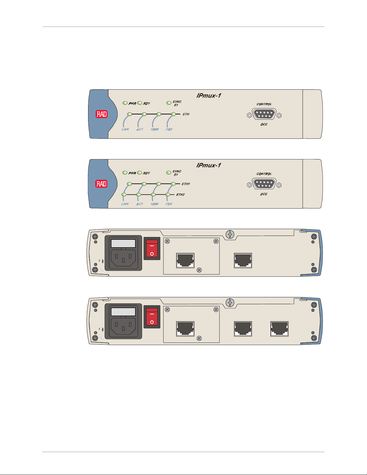
IPmux-1/1E Installation and Operation Manual Chapter 2 Installation
Connecting Interfaces and Cables
Figure 2-2 through Figure 2-5 illustrate the front and rear panel options available
for IPmux-1.
Figure 2-6 through Figure 2-9 illustrate the rear and front panel options available
for IPmux-1E.
Figure 2-2. IPmux-1 Front Panel
100-230 VAC
1.6A T 250V
100-230 VAC
1.6A T 250V
Figure 2-3. IPmux-1 Front Panel for Two Ethernet Ports
POWER
:
CAUTION
FOR CON TINUED
PROTECTION AGAINST RISK OF
FIRE, REPLACE ONLY WITH SAME
TYPE AND RATING OF FUSE.
E1 ETH
Figure 2-4. IPmux-1 Rear Panel
POWER
:
FOR CON TINUED
CAUTION
PROTECTION AGAINST RISK OF
FIRE, REPLACE ONLY WITH SAME
TYPE AND RATING OF FUSE.
E1
ETH
Figure 2-5. IPmux-1 Rear Panel for Two Ethernet Ports
NETWORKUSER
Installation and Setup 2-5
Page 73

Chapter 2 Installation IPmux-1/1E Installation and Operation Manual
IPmux-1E
Figure 2-6. IPmux-1E Front Panel
IPmux-1E
Figure 2-7. IPmux-1E Front Panel for Two Ethernet Ports
CAUTION
1.6A T 250V
100-240 VAC
CAUTION
1.6A T 250V
100-240 VAC
Warning
:
POWER
IISDN
S
1234
I/O
3
Figure 2-8. IPmux-1E Rear Panel (ISDN BRI Option)
:
POWER
IISD N
S
1234
I/O
3
Figure 2-9. IPmux-1E Rear Panel (ISDN BRI Option) for Two Ethernet Ports
Grounding
Interrupting the protective grounding conductor (inside or outside the instrument)
or disconnecting the protective earth terminal can make this instrument
dangerous. Intentional interruption is prohibited.
Before switching ON this instrument and before connecting any other cable,
the protective earth terminals of this instrument must be connected to the
protective ground conductor of the power cord.
Fuses
Make sure that only fuses with the required rated current and specified type, as
marked on the IPmux-1/1E rear panel, are used for replacement: 1.6A T 250V.
Whenever it is likely that the protection offered by fuses has been impaired, the
instrument must be made inoperative and secured to prevent any operation.
2-6 Installation and Setup
Page 74

IPmux-1/1E Installation and Operation Manual Chapter 2 Installation
Location of Connectors
Interface connections are made from the IPmux-1/1E back panel, as shown in
Figure 2-2.
• Table 2-1 lists the E1/T1 port pinout.
• Table 2-2 lists the Ethernet port pinout.
• Table 2-3 lists the Control port pinout.
• Table 2-4 lists the ISDN-S connector pinout.
• Table 2-5 lists the FXS/FXO/E&M connector pinout for RJ-11.
Table 2-1. E1/T1 Port Connectors Pinout
Pin Designation Direction Function
1 RD (R) Input Receive data (ring)
2 RD (T) Input Receive data (tip)
3, 6 – – FGND
4 TD (R) Output Transmit data (ring)
5 TD (T) Output Transmit data (tip)
7, 8 – N/A Not connected
Table 2-2. Ethernet Port Pinout
Pin Pinout
1 Tx+
2 Tx–
3 Rx+
4 –
5 –
6 Rx–
7 –
8 –
Installation and Setup 2-7
Page 75

Chapter 2 Installation IPmux-1/1E Installation and Operation Manual
Table 2-3. Control Port Pinout
Pin Pinout
1 –
2 Rx
3 Tx
4 –
5 GND
6 –
7 –
8 –
9 –
Table 2-4. ISDN-S-Interface Pin Assignments
Pin Number Signal Name
3 Tx+
4 Rx+
5 Rx–
6 Tx–
2-8 Installation and Setup
Page 76

IPmux-1/1E Installation and Operation Manual Chapter 2 Installation
Table 2-5. E&M Interface Pin Assignments for RJ-11
Pin Number Designation Function
1 SB Signaling battery
2 M M lead input
3 R1-0UT 4-wire voice output
2-wire voice input/output
4 R-IN 4-wire voice input
5 T-IN 4-wire voice input
6 T1-OUT 4-wire voice output
2-wire voice input/output
7 SC Function depends on signalling mode:
RS-464 Type I, III: Direct connection to signal
ground
RS-464 Type V, SSDCS: Connection to signal
ground through 1.1 kΩ resistor
RS-464 Type II: SG lead
8 E E lead output
Table 2-6. FXS/FXO Interface Pin Assignments for RJ-11
Pin Number Designation Direction Function
1, 2 Not connected
3 RING IN/OUT two-wire input/output
4 TIP IN/OUT two-wire input/output
5, 6 Not connected
Connecting the Control Port
The Control port is located on the IPmux-1/1E front panel (Figure 2-2). The
External Clock port pinout is shown in Figure 2-10 listed in Table 2-7.
5
678
1234
Figure 2-10. External Clock Port Pinout
Installation and Setup 2-9
Page 77

Chapter 2 Installation IPmux-1/1E Installation and Operation Manual
Table 2-7. External Clock Port Pinout
Pin Number Signal Name Function
1 RRING Rx
2 RTIP Rx
3 GND Usually not connected
4 TRING Tx
5 TTIP Tx
6 GND Usually not connected
7 – Not connected
8 – Not connected
Connecting the Power
To connect power to IPmux-1/1E, refer to the appropriate section below,
depending on your version of the unit (AC or DC).
AC Power Connection
AC power is supplied to IPmux-1/1E through the 5-ft (1.5m) standard power cable
terminated by a standard 3-prong plug. The cable is supplied with the unit.
To connect AC power to IPmux-1/1E:
1. Verify that the AC outlet is grounded properly. Ensure that the supply voltage is
in the range 100 VAC to 240 VAC.
2. Check that the Power switch on the rear panel is set to OFF.
3. Connect the power cable to the rear panel connector first and then to the
AC mains outlet.
2-10 Installation and Setup
Page 78

IPmux-1/1E Installation and Operation Manual Chapter 2 Installation
DC Power Connection
A DC power supply option is available to be ordered for IPmux-1 only (not
available for IPmux-1E. For information about connecting the DC power supply
refer to the DC Power Supply Connection Supplement.
Due to the high current capability of DC mains systems, care should be taken
when connecting the DC supply, in order to avoid short-circuits and fire
hazards.
Warning
DC units should be installed in a restricted access area, i.e., an area where
access is authorized only to qualified service and maintenance personnel.
Make sure that the DC supply is electrically isolated from any AC source, and
that the installation complies with the local codes.
The maximum permissible current capability of the branch distribution circuit
that supplies power to the product is 16A.
Before connecting the DC input plug, ensure that power is removed from the
DC circuit. Locate the circuit breaker of the panel board that services the
equipment, and switch it to the OFF position. When connecting the other end
of the DC cable, first connect the ground wire, then the position pole, and
lastly the negative pole. Switch the circuit breaker back to the ON position.
A readily accessible disconnect device that is suitably rated and approved
should be incorporated in the building installation.
Installation and Setup 2-11
Page 79

Chapter 2 Installation IPmux-1/1E Installation and Operation Manual
2-12 Installation and Setup
Page 80

Chapter 3 Operation
This chapter:
• Provides a detailed description of the front panel controls and indicators and
their functions
• Explains power-on and power-off procedures
• Provides instructions for using a terminal connected to the IPmux-1/1E Control
port
• Describes how to navigate menus
• Illustrates the following menus:
− Main menu
− Configuration menu
− Viewing System Information
− Monitoring IPmux-1/1E performance.
For a detailed explanation of parameters on the menus, see Appendix E.
3.1 Front Panel Controls, Connectors, and Indicators
The unit's LEDs (see Figure 3-1, Figure 3-2, Figure 3-3 and Figure 3-4) are located
on the left side of the front panel. Table 3-1 and Table 3-2 list the functions of the
IPmux-1 and IPmux-1E system indicators and switches.
Front Panel Controls, Connectors, and Indicators 3-1
Page 81

Chapter 3 Operation IPmux-1/1E Installation and Operation Manual
3
2
4 5
1
7
Figure 3-1. IPmux-1 Front Panel LEDs
8
POWER
:
FOR CON TINUED
CAUTION
PROTECTION AGAINST RISK OF
FIRE, REPLACE ONLY WITH SAME
100-230 VAC
TYPE AND RATING OF FUSE.
1.6A T 250V
E1 ETH
Figure 3-2. IPmux-1 Rear Panel Switch
Table 3-1. IPmux-1 System Indicators and Switches
No. Name Type Function
1 PWR LED On: Unit powered
Off: Unit not powered
2 RDY LED On: Device OK
Off: Self-test in progress
Blinking: Malfunction detected
3 SYNC E1 LED On: Port synchronized (no alarm)
Off: Unframed: Signal loss or AIS detected
Framed: Signal loss, loss of frame or AIS detected
Blinking: RDI detected (remote alarm)
4 ETH LINK LED On: Line OK
Off: Link not active
5 ETH ACT LED On: Frame being transferred on line
6 ETH 100M LED On: 100 Mbps
3-2 Front Panel Controls, Connectors, and Indicators
Off: No activity
Off: 10 Mbps
Page 82

IPmux-1/1E Installation and Operation Manual Chapter 3 Operation
Table 3-1. IPmux-1 System Indicators and Switches (Cont.)
No. Name Type Function
7 ETH FDX LED On: Full-duplex
Off: Half-duplex
8 POWER Switch Turns IPmux-1/1E power On and Off
1
2
IPmux-1E
4 5 6 7
3
Figure 3-3. IPmux-1E Front Panel Indicators
8
:
CAUTION
1A T 250V
100-240 VAC
POWER
IISDN
S
123 4
I/O
3
Figure 3-4. IPmux-1E Back Panel Indicators
Table 3-2. IPmux-1E (BRI/FXS/FXO/E&M) System Indicators and Switches
No. Name Type Function
1 PS1 Green On: Unit powered
Red On: Power supply failure
Off: Unit not powered
2 RDY LED On: Device OK
Off: Self-test in progress
Blinking: Malfunction detected
3 SYNC
CH1–CH4
LED ISDN
FXS/FXO/E&M
On: ISDN synchronized
Off: ISDN LOF
On: OFF hook
Off: ON hook
Blinking: Ringing
Front Panel Controls, Connectors, and Indicators 3-3
Page 83

Chapter 3 Operation IPmux-1/1E Installation and Operation Manual
Table 3-2. IPmux-1E (BRI/FXS/FXO/E&M) System Indicators and Switches (Cont.)
No. Name Type Function
4 ETH LINK LED On: Line OK
Off: Link not active
5 ETH ACT LED On: Frame being transferred on line
Off: No activity
6 ETH
100M
7 ETH FDX LED On: Full-duplex
8 POWER Switch Turns IPmux-1E power ON and OFF
3.2 Operating Instructions
Turning IPmux-1/1E On
Without Control Terminal
The IPmux-1/1E power switch is located on the back panel, as shown in
Figure 3-2.
To power up IPmux-1/1E without a control terminal:
1. Turn ON the power supply switch, located on the rear panel, to ON.
2. Check the unit LED indicators, located on the left side of the front panel, and
the module indicators for proper operation (see Figure 3-1, Figure 3-2,
Figure 3-3, Figure 3-4, Table 3-1, and Table 3-2).
LED On: 100 Mbps
Off: 10 Mbps
Off: Half-duplex
With Control Terminal
To power up IPmux-1/1E with a Control terminal:
1. Make sure all IPmux-1/1E cables and connectors are properly connected.
2. Connect IPmux-1/1E to a PC equipped with an ASCII terminal-emulation
application (for example, Windows 95 Hyper Terminal or Procomm).
3. Turn on the control-terminal PC and set its default port parameters to
19,200 baud, 8 bits/character, 1 stop bit, No Parity. Set the terminal emulator
to ANSI VT100 emulation (for optimal view of system menus).
4. Switch ON the POWER supply switch, located on the rear panel.
5. When the initialization and self-test are over, a menu appears displaying
initialization and self-test results. If the self-test is successful, the RDY LED
(Figure 3-1 and Figure 3-3) on the left side of the front panel lights. If problems
are encountered, refer to Chapter 4 for instructions.
3-4 Operating Instructions
Page 84

IPmux-1/1E Installation and Operation Manual Chapter 3 Operation
6. Press <Esc> to open the configuration software.
7. Enter your User Name according to your assigned system privileges (either
Supervisor (su) or User and then your Password when prompted (the
factory-set password is xxxxxxxxxx).
The Main Menu is displayed (Figure 3-11).
Note
If the password is invalid in three consecutive attempts, the system becomes
inaccessible for 15 minutes.
Login
User Name and Password
To enter as a superuser:
1. Enter su for User Name.
2. Enter xxxxxxxxxx for Password.
This allows you to configure all the parameters of IPmux-1/1E, and to change the
su and user passwords.
To view the unit’s comfiguration:
1. Enter user for User Name.
2. Enter xxxxxxxxxx for Password.
This does not allow you to make configuration changes.
To set all passwords to the default value (xxxxxxxxxx):
• Delete the unit’s configuration through the Configuration screens.
Note
Deleting the unit’s configuration using <Cntl+A> and choosing 4 in the Boot
Menu does not set the password to the default value.
Turning IPmux-1/1E Off
To power off the unit:
• Switch PWR to OFF.
Operating Instructions 3-5
Page 85

Chapter 3 Operation IPmux-1/1E Installation and Operation Manual
3.3 Getting Started
After installation, there are no special operating procedures for IPmux-1/1E. Once
it is powered up, the unit operates automatically. The front panel LED indicators
(Figure 3-1 and Figure 3-3) indicate proper operation. The unit operational status
can be monitored constantly.
If required, IPmux-1/1E can be reconfigured. Both the IPmux-1/1E configuration
and monitoring operations are performed locally from an ASCII terminal
connected to the Control port. Detailed configuration procedures are given in
Overview of Menu Operations and Appendix E.
The following functions are supported (see menu trees in Figure 3-5, Figure 3-6,
Figure 3-7, Figure 3-8, Figure 3-9, and Figure 3-10):
• Viewing system information
• Modifying configuration and mode of operation, including setting system
default values
• Viewing statistics and status.
Navigating
3.4 Overview of Menu Operations
Navigate the IPmux-1/1E terminal menus to set and view configuration
parameters:
• Figure 3-5 maps the IPmux-1 terminal menus except for the Connection
Configuration menu.
• Figure 3-6 maps the IPmux-1E ISDN-S terminal menus except for the
Connection Configuration menu.
• Figure 3-7 maps the IPmux-1E FXS/FXO/E&M terminal menus except for the
Connection Configuration menu.
• Figure 3-8 maps the IPmux-1E Connection Configuration menu for Static
Mode.
• Figure 3-9 maps the IPmux-1E Connection Configuration menu for Dynamic
CAS Mode.
• Figure 3-10 maps the IPmux-1E Connection Configuration menu for CESoIP
Mode.
Use these menu trees as a reference aid while performing configuration and
control functions. Appendix E illustrates menus, explains parameters, and lists
default values. Refer to Appendix E to find specific parameters.
3-6 Overview of Menu Operations
Page 86

IPmux-1/1E Installation and Operation Manual Chapter 3 Operation
Main Menu
1. System
1. General
Configuration
1. Host IP
2. Management
3. ASCII Terminal
4.Time/Date Update
5. Software
1.General
Information
2.Self-Test
Results
3. Reset
4.Event Log
5. Ping
Configuration
Configuration
Download/Upload
2. E1/T1
Configuration
1. Channel Status
2. Transmit Clock
Source
3. Loopback State
4. Rx Sensitivity
5. Line Type
2. Configuration 4. Exit
3.Connection
Configuration
Continued in
Figures 3-8
(Static Mode),
3-9 (Dynamic
CAS Mode),
and 3-10
(CESoIP
Mode)
3.Performance
Monitoring
One-port
LAN Option
4.LAN
Configuration
Two-port
LAN Option
4. Switch
Configuration
1. E1/T1 Statistics
2.LAN Status
3. Bundle
Connection Status
4.Bundle Connection
Statistics
5.DS0 Bundle
Configuration
1. Auto
Negotiation
2. Max
Capability
Advertised
3. Default Type
1.Bundle ID
2.Time Slot
Number
3.Time Slot
Current Status
6. Set Default
Parameters
7.System Name
8.System Location
6. Idle Code
7. Signaling Mode
8. Cond. Data
Pattern
9.Cond. CAS
(ABCD) Pattern
1. LAN
Configuration
2. Aging Time
3. Erase MAC
Table
4. VLAN
Configuration
Figure 3-5. IPmux-1 (E1/T1) Terminal Menu Tree
Overview of Menu Operations 3-7
Page 87

Chapter 3 Operation IPmux-1/1E Installation and Operation Manual
Main Menu
1. System
1. General
Configuration
1. Host IP
2. Management
3. ASCII Terminal
1.General
Information
2.Self-Test
Results
3. Reset
4.Event Log
5. Ping
Configuration
Configuration
2. ISDN
Configuration
1. Interfaces Mode
2. Transmit Clock
Source
3. Channel
Configuration
2. Configuration 4. Exit
3.Connection
Configuration
Continued in
Figures 3-8
(Static Mode),
3-9 (Dynamic
CAS Mode),
and 3-10
(CESoIP
Mode)
3.Performance
Monitoring
ISDN Statistics
2.LAN Status
3. Bundle
Connection Status
4.Bundle Connection
Statistics
One-port
LAN Option
4.LAN
Configuration
1. Auto
Negotiation
2. Max
Capability
Advertised
3. Default Type
4.Time/Date Update
5. Software
Download/Upload
6. Set Default
Parameters
7.System Name
8.System Location
Two-port
LAN Option
4. Switch
Configuration
1. LAN
Configuration
2. Aging Time
3. Erase MAC
Table
4. VLAN
Configuration
Figure 3-6. IPmux-1E ISDN-S Terminal Menu Tree
3-8 Overview of Menu Operations
Page 88

IPmux-1/1E Installation and Operation Manual Chapter 3 Operation
Main Menu
1. System
1. General
Configuration
1. Host IP
2. Management
3. ASCII Terminal
1.General
Information
2.Self-Test
Results
3. Reset
4.Event Log
5. Ping
Configuration
Configuration
2. Analog
Configuration
1. Clock Source
2. Far End Type
3. Channel
Configuration
2. Configuration 4. Exit
3.Connection
Configuration
Continued in
Figures 3-8
(Static Mode),
3-9 (Dynamic
CAS Mode),
and 3-10
(CESoIP
Mode)
3.Performance
Monitoring
1. Analog Status
2.LAN Status
3. Bundle
Connection Status
4.Bundle Connection
Statistics
One-port
LAN Option
4.LAN
Configuration
1. Auto
Negotiation
2. Max
Capability
Advertised
3. Default Type
4.Time/Date Update
5. Software
Download/Upload
6. Set Default
Parameters
7.System Name
8.System Location
4. Signaling Profile
Configuration
5. Line Type
6. Idle Code
7. Signaling Mode
8. Cond. Data
Pattern
9.Cond. CAS
(ABCD) Pattern
Two-port
LAN Option
4. Switch
Configuration
1. LAN
Configuration
2. Aging Time
3. Erase MAC
Table
4. VLAN
Configuration
Figure 3-7. IPmux-1E FXS/FXO/E&M Terminal Menu Tree
Overview of Menu Operations 3-9
Page 89

Chapter 3 Operation IPmux-1/1E Installation and Operation Manual
Main Menu
2.Configuration
3.Connection
Configuration
1.Connection
Mode
2. Bundle Connection
Configuration
1. Bundle ID
2. IP TOS
3. TDM Bytes in a
Frame
4. Connection Status
5. Destination IP
Address
6. Next Hop
7. Destination
Bundle
8. Jitter Buffer
9. OAM Connectivity
A. Redundancy
Function
3. Secondary IP
Address
4. Secondary IP
Mask
5. Protection Switching
Configuration
1. Primary Bundle ID
2. Secondary Bundle
ID
3. Redundancy Type
4. TDM Fail Time
5. Event Threshold
Window
6. Sequence Number
Threshold
7.Underflow/Overflow
Threshold
8. Local Fail Time
9. Force Connection
A. Recovery
Figure 3-8. IPmux-1/1E Connection Configuration Menu Tree for Static Mode
3-10 Overview of Menu Operations
B. VLAN Tagging
C. VLAN ID
E. VLAN Priority
B. Wait-To-Restore
Time
Page 90

IPmux-1/1E Installation and Operation Manual Chapter 3 Operation
Main Menu
2.Configuration
3.Connection
Configuration
1.Connection
Mode
2. Bundle Connection
Configuration
1. Bundle ID
2. IP TOS
3. Active Time Slot
Bytes in Frame
4. Connection Status
5. Destination IP
Address
6. Next Hop
7. Destination
Bundle
8. Jitter Buffer
9. OAM Connectivity
A. Redundancy
Function
3. Activation Criterion
1. Pattern ID
2. Tx A
3. Tx B
4. Tx C
5. Tx D
B. VLAN Tagging
C. VLAN ID
E. VLAN Priority
Figure 3-9. IPmux-1E Connection Configuration Menu Tree for Dynamic CAS Mode
Overview of Menu Operations 3-11
Page 91

Chapter 3 Operation IPmux-1/1E Installation and Operation Manual
Main Menu
2.Configuration
3.Connection
Configuration
1.Connection
Mode
2. Bundle Connection
Configuration
1. Bundle ID
2. IP TOS
3. Packet Delay
4. Connection Status
5. Destination IP
Address
6. Next Hop
7. Source UDP
8. Destination UDP
9. Jitter Buffer
B. VLAN Tagging
Figure 3-10. IPmux-1E Connection Configuration Menu Tree for CESoIP Mode
Main Menu
Figure 3-11 shows the IPmux-1/1E Main Menu. Access all system configuration and
control functions via this menu.
The Main Menu options are described in Table 3-3.
At any point and from any screen, you can press <Esc> repeatedly, backing up
until you reach the main menu.
You exit the program only from this menu. In order to prevent unauthorized
access, it is recommended that when you finish a session, you return to the Main
Menu and type 4 to exit the program. A password is then required for reentry.
3-12 Overview of Menu Operations
C. VLAN ID
E. VLAN Priority
Page 92

IPmux-1/1E Installation and Operation Manual Chapter 3 Operation
Table 3-3. IPmux-1/1E Main Menu Options
Option Description
1. System View and modify system parameters
2. Configuration Define system configuration
3. Performance Monitoring Monitor system performance
4. Exit Exit the control software
MAIN MENU
1.System >
2.Configuration >
3.Performance Monitoring >
4.Exit
Select item from the menu: _
Use keys <1> to <4>
Figure 3-11. IPmux-1/1E Main Menu
System Menu
Main Menu
↓
1. System
To access the System menu:
• Type 1 (System) in the Main Menu.
From the System menu (see Figure 3-12) you can view and configure the options
described in Table 3-4. These options are explained in full detail in Appendix E.
Table 3-4. IPmux-1/1E System Menu Options
Option Description
1. General Information View IPmux-1/1E general information
2. Self-Test Results Review self-test results obtained during system
power-up.
3. Reset Reset IPmux-1/1E
4. Event Log View a list of IPmux-1/1E events
5. Ping Ping other network devices
Overview of Menu Operations 3-13
Page 93

Chapter 3 Operation IPmux-1/1E Installation and Operation Manual
SYSTEM
1. General Information
2. Self-Test Results
3. Reset
4. Event Log >
5. Ping
ESC. Exit
Select item from the menu.
Figure 3-12. IPmux-1/1E System Menu
Setting IPmux-1/1E Configuration Options
To access the Configuration menu:
Main Menu
↓
2. Configuration
• Type 2 (Configuration) in the Main Menu.
The IPmux-1E E1/T1 Configuration menu is shown in Figure 3-5 and Figure
3-13.
The IPmux-1E ISDN-S Configuration menu is shown in Figure 3-6 and
Figure 3-14.
The IPmux-1E FXS/FXO/E&M Configuration menu is shown in Figure 37and Figure 3-15.
Table 3-5 describes the configuration options.
CONFIGURATION
1. General Configuration
2. E1/T1 Configuration
3. Connection Configuration
4. Switch Configuration
5. DS0 Bundle Configuration
ESC. Exit
Select item from the menu: _
Figure 3-13. IPmux-1/1E Configuration Menu
3-14 Overview of Menu Operations
Page 94

IPmux-1/1E Installation and Operation Manual Chapter 3 Operation
CONFIGURATION
1. General Configuration
2. ISDN Configuration
3. Connection Configuration
4. LAN Configuration
ESC. Exit
Select item from the menu: _
Figure 3-14. IPmux-1E ISDN-S Configuration Menu
CONFIGURATION
1. General Configuration
2. Analog Configuration
3. Connection Configuration
4. LAN Configuration
ESC. Exit
Select item from the menu: _
Figure 3-15. IPmux-1E FXS/FXO/E&M Configuration Menu
From the Configuration menu you can view and configure the following options:
Table 3-5. Configuration Options
Option Description
1. General Configuration Configure Host IP, Default Gateway, ASCII Terminal Configuration,
Time/Date update, and Default parameters, and download software
updates
2. E1/T1/ISDN/FXS/FXO/E&M
Configuration
3. Connection Configuration Configure IP ToS, TDM bytes/frame, VLAN tagging, and Redundancy
4. LAN Configuration Configure Ethernet physical layer
5. DS0 Bundle Configuration Configure TS assignment to the bundle (Note: only for IPmux-1)
Configure E1/T1, ISDN, FXS, FXO, or E&M physical layer
Function
Specific parameters are explained in Appendix E.
Overview of Menu Operations 3-15
Page 95

Chapter 3 Operation IPmux-1/1E Installation and Operation Manual
Performance Monitoring
To view Performance Statistics:
• Type 3 (Performance Monitoring) in the Main menu.
Typical menus are shown in Figure 3-16, Figure 3-17, and Figure 3-18.
Table 3-6 describes the Performance Monitoring options.
Further details for specific parameters are explained in Appendix E.
PERFORMANCE MONITORING
1. E1/T1 Statistics
2. LAN Status
3. Bundle Connection Status
4. Bundle Connection Statistics
ESC. Exit
Select item from the menu.
Figure 3-16. Performance Monitoring Menu for IPmux-1
PERFORMANCE MONITORING
1. ISDN Statistics
2. LAN Status
3. Bundle Connection Status
4. Bundle Connection Statistics
ESC. Exit
Select item from the menu.
Figure 3-17. Performance Monitoring Menu for IPmux-1E ISDN-S
3-16 Overview of Menu Operations
Page 96

IPmux-1/1E Installation and Operation Manual Chapter 3 Operation
PERFORMANCE MONITORING
1. Analog Status
2. LAN Status
3. Bundle Connection Status
4. Bundle Connection Statistics
ESC. Exit
Select item from the menu.
Figure 3-18. Performance Monitoring Menu for IPmux-1E FXS/FXO/E&M
Table 3-6. Performance Monitoring Menu Options
Option Description
1. E1/T1/ ISDN/ Analog Statistics Statistics for E1/T1, ISDN, or FXS/FXO/E&M – updated at 15 minute
intervals
2. LAN Status Status of Lan port(s)
3. Bundle Connection Status Status of defined connections
4. Bundle Connection Statistics Statistics for defined connections – updated at 15 minute intervals
Overview of Menu Operations 3-17
Page 97

Chapter 3 Operation IPmux-1/1E Installation and Operation Manual
3-18 Overview of Menu Operations
Page 98

Chapter 4
Troubleshooting and
Diagnostics
This chapter describes how to:
• Detect errors
• Troubleshoot problems
• Perform diagnostic tests.
4.1 Error Detection
Using Front Panel LEDs
LED indicators on the front panel IPmux-1/1E indicate the operating status of the
module. The LED indicators are described in Chapter 3 of this manual.
Working with the Alarm Buffer
IPmux-1/1E maintains an Event Log File. All events are time-stamped. The user can
view the contents of the Event Log File via an ASCII terminal or a Telnet Session.
The user can also clear the contents of the Log File.
Table 4-1 presents the event types that appear on the Event Log File alphabetically,
as well as the actions required to correct the event (alarm) indication.
To correct the reported problem, perform corrective actions in the given order
until the problem is corrected. If the problem cannot be fixed by carrying out the
listed actions, IPmux-1/1E MUST be checked by the authorized technical support
personnel.
Error Detection 4-1
Page 99

Chapter 4 Troubleshooting and Diagnostics IPmux-1/1E Installation and Operation Manual
Table 4-1. Event Types
Event Description Corrective Action
COLD START IPmux-1/1E has been powered up None
CON LOCAL FAIL Ethernet frames are not received by the
local IPmux-1 on the specified
connection
CON REMOTE FAIL Ethernet frames are not received by the
remote IPmux-1 on the specified
connection
CON STANDBY Redundancy bundle connection is not
the active connection (only applies
when redundancy is used)
CON TDM FAIL LOS/LOF on the TDM line forced
redundancy switching (only applies
when redundancy is used)
CON SYNC Bundle connection failure has ended
(only applicable when OAM is Enabled)
CON UNAVAILABLE Remote IPmux is not available (only
applicable when OAM is Enabled)
CON VALIDATION FAIL Connection is invalid (only applicable
when OAM is Enabled)
FATAL ERROR IPmux-1/1E has encountered an
internal fatal error
IP ADDRESS IS ASSIGNED BY
SERVER
Host IP has been learned by the DHCP
protocol
Check Eth/IP path
Check Eth/IP path
None
Check the TDM line
None
Check the connection of the remote IPmux
Check the bundle parameters
The IPmux-1/1E requires servicing
None
IP ADDRESS IS RELEASED Host IP has been relesased by the
DHCP protocol
JIT BUF OFLOWS END
BUNDLE 1
JIT BUF OFLOWS START
BUNDLE 1
JIT BUF UFLOWS END
BUNDLE 1
JIT BUF UFLOWS START
BUNDLE 1
LINE AIS END Line AIS state detected has ended None
LINE AIS START IPmux-1 has AIS (alarm indicator signal)
LINE FEBE END LINE FEBE state detected has ended None
LINE FEBE START IPmux-1 has LINE FEBE state on its
LINE RDI END LINE RDI state detected has ended None
LINE RDI START IPmux-1 has LINE RDI (remote defect
*Jitter Buffer Overflows END
*Jitter Buffer Overflows START
*Jitter Buffer Underflows END
*Jitter Buffer Underflows START
state on its E1/T1 port
E1/T1 port
indicator) state on its E1/T1 port
Check the connection with the DHCP server
Refer to Bundle Configuration Statistics in
Appendix E
Refer to Bundle Configuration Statistics in
Appendix E
Refer to Bundle Configuration Statistics in
Appendix E
Refer to Bundle Configuration Statistics in
Appendix E
Check for a fault at the PDH network, on the
receive direction
Check for errors in the E1/T1 connection on
the transmit direction
Check for a fault at the E1/T1 connectivity
on the transmit direction
4-2 Error Detection
Page 100

IPmux-1/1E Installation and Operation Manual Chapter 4 Troubleshooting and Diagnostics
Table 4-1. Event Types (Cont.)
Event Description Corrective Action
LOS END LOS state detected has ended None
LOS START IPmux-1 has a LOS (loss of signal) state
on its E1/T1 port
PS ACTIVE IPmux-1/1E power supply unit is
powered on
SN ERRORS END
BUNDLE 1
SN ERRORS START
BUNDLE 1
SYSTEM USER RESET IPmux-1/1E was reset by the user None
You can configure whether an item will be displayed for each event or every
*
*Sequence Number ERRORS END
*Sequence Number ERRORS START
1. Check the port cable connection
2. Check input signal
None
Refer to Bundle Configuration Statistics in
Appendix E
Refer to Bundle Configuration Statistics in
Appendix E
1 sec / 1 min. For further information see Logfile Events in Appendix E.
Error Detection 4-3
 Loading...