

Page 1
Americas Headquarters
Cisco Systems, Inc.
170 West Tasman Drive
San Jose, CA 95134-1706
USA
http://www.cisco.com
Tel: 408 526-4000
800 553-NETS (6387)
Fax: 408 527-0883
Cisco IOS XR Getting Started Guide
Cisco IOS XR Software Release 3.4
Text Part Number: OL-10957-02
Page 2

THE SPECIFICATIONS AND INFORMATION REGARDING THE PRODUCTS IN THIS MANUAL ARE SUBJECT TO CHANGE WITHOUT NOTICE. ALL
STATEMENTS, INFORMATION, AND RECOMMENDATIONS IN THIS MANUAL ARE BELIEVED TO BE ACCURATE BUT ARE PRESENTED WITHOUT
WARRANTY OF ANY KIND, EXPRESS OR IMPLIED. USERS MUST TAKE FULL RESPONSIBILITY FOR THEIR APPLICATION OF ANY PRODUCTS.
THE SOFTWARE LICENSE AND LIMITED WARRANTY FOR THE ACCOMPANYING PRODUCT ARE SET FORTH IN THE INFORMATION PACKET THAT
SHIPPED WITH THE PRODUCT AND ARE INCORPORATED HEREIN BY THIS REFERENCE. IF YOU ARE UNABLE TO LOCATE THE SOFTWARE LICENSE
OR LIMITED WARRANTY, CONTACT YOUR CISCO REPRESENTATIVE FOR A COPY.
The Cisco implementation of TCP header compression is an adaptation of a program developed by the University of California, Berkeley (UCB) as part of UCB’s public
domain version of the UNIX operating system. All rights reserved. Copyright © 1981, Regents of the University of California.
NOTWITHSTANDING ANY OTHER WARRANTY HEREIN, ALL DOCUMENT FILES AND SOFTWARE OF THESE SUPPLIERS ARE PROVIDED “AS IS” WITH
ALL FAULTS. CISCO AND THE ABOVE-NAMED SUPPLIERS DISCLAIM ALL WARRANTIES, EXPRESSED OR IMPLIED, INCLUDING, WITHOUT
LIMITATION, THOSE OF MERCHANTABILITY, FITNESS FOR A PARTICULAR PURPOSE AND NONINFRINGEMENT OR ARISING FROM A COURSE OF
DEALING, USAGE, OR TRADE PRACTICE.
IN NO EVENT SHALL CISCO OR ITS SUPPLIERS BE LIABLE FOR ANY INDIRECT, SPECIAL, CONSEQUENTIAL, OR INCIDENTAL DAMAGES, INCLUDING,
WITHOUT LIMITATION, LOST PROFITS OR LOSS OR DAMAGE TO DATA ARISING OUT OF THE USE OR INABILITY TO USE THIS MANUAL, EVEN IF CISCO
OR ITS SUPPLIERS HAVE BEEN ADVISED OF THE POSSIBILITY OF SUCH DAMAGES.
Any Internet Protocol (IP) addresses used in this document are not intended to be actual addresses. Any examples, command display output, and figures included in the
document are shown for illustrative purposes only. Any use of actual IP addresses in illustrative content is unintentional and coincidental.
Cisco IOS XR Getting Started Guide
© 2007 Cisco Systems, Inc. All rights reserved.
CCVP, the Cisco Logo, and the Cisco Square Bridge logo are trademarks of Cisco Systems, Inc.; Changing the Way We Work, Live, Play, and Learn is a service mark of Cisco Systems,
Inc.; and Access Registrar, Aironet, BPX, Catalyst, CCDA, CCDP, CCIE, CCIP, CCNA, CCNP, CCSP, Cisco, the Cisco Certified Internetwork Expert logo, Cisco IOS, Cisco
Press, Cisco Systems, Cisco Systems Capital, the Cisco Systems logo, Cisco Unity, Enterprise/Solver, EtherChannel, EtherFast, EtherSwitch, Fast Step, Follow Me Browsing,
FormShare, GigaDrive, GigaStack, HomeLink, Internet Quotient, IOS, iPhone, IP/TV, iQ Expertise, the iQ logo, iQ Net Readiness Scorecard, iQuick Study, LightStream,
Linksys, MeetingPlace, MGX, Networking Academy, Network Registrar, Pac k et , PIX, ProConnect, RateMUX, ScriptShare, SlideCast, SMARTnet, StackWise, The Fastest Way
to Increase Your Internet Quotient, and TransPath are registered trademarks of Cisco Systems, Inc. and/or its affiliates in the United States and certain other countries.
All other trademarks mentioned in this document or Website are the property of their respective owners. The use of the word partner does not imply a partnership relationship
between Cisco and any other company. (0612R)
Page 3

iii
Cisco IOS XR Getting Started Guide
OL-10957-02
CONTENTS
Preface ix
Changes to This Document ix
About This Document ix
Intended Audience x
Organization of the Document x
Related Documents x
Conventions xi
Obtaining Documentation xi
Cisco.com xi
Product Documentation DVD xii
Ordering Documentation xii
Documentation Feedback xii
Cisco Product Security Overview xii
Reporting Security Problems in Cisco Products xiii
Product Alerts and Field Notices xiii
Obtaining Technical Assistance xiv
Cisco Technical Support & Documentation Website xiv
Submitting a Service Request xv
Definitions of Service Request Severity xv
Obtaining Additional Publications and Information xv
CHAPTER
1 Introduction to Cisco IOS XR Software 1-1
Contents 1-1
Supported Standalone System Configurations 1-1
Cisco CRS-1 Multishelf System Overview 1-2
Router Management Interfaces 1-6
Command-Line Interface 1-6
Craft Works Interface 1-6
Extensible Markup Language API 1-6
Simple Network Management Protocol 1-7
Selecting and Identifying the Designated Shelf Controller 1-7
Selecting and Identifying the DSC on Cisco CRS-1 Routers 1-8
Selecting and Identifying the DSC on Cisco CRS-1 Multishelf Systems 1-8
Selecting and Identifying the DSC on Cisco XR 12000 and 12000 Series Routers 1-9
Page 4

Contents
iv
Cisco IOS XR Getting Started Guide
OL-10957-02
Connecting to the Router Through the Console Port 1-9
Where to Go Next 1-14
CHAPTER
2 Bringing Up the Cisco IOS XR Software on a Standalone Router 2-1
Contents 2-1
Prerequisites 2-1
Software Requirements 2-1
Hardware Prerequisites and Documentation 2-2
Bringing Up and Configuring a Standalone Router 2-2
Verifying the System After Initial Bring-Up 2-4
Where to Go Next 2-8
CHAPTER
3 Bringing Up the Cisco IOS XR Software on a Multishelf System 3-1
Contents 3-1
Prerequisites 3-1
Software Requirements 3-1
Hardware Requirements 3-2
Restrictions 3-2
Information About Bringing Up a Multishelf System 3-3
Bringup Overview 3-3
Preparing a Rack Number Plan 3-3
Configuring the External Cisco Catalyst 6509 Switches 3-8
Prerequisites 3-9
Restrictions 3-10
Before You Begin 3-10
Information About the Catalyst Switch Configuration 3-11
Configuring the Catalyst Switches 3-11
Verifying the Catalyst Switch 3-18
Integrated Switch System 3-20
Prerequisites for an Integrated Switch System 3-20
Restrictions for an Integrated Switch System 3-21
Before You Begin 3-21
Information About the Integrated Switch Implementation 3-21
Implementing the Integrated Switch System 3-23
Verifying the Connections of the Integrated Switch Control Network 3-25
Bringing Up and Configuring Rack 0 3-28
Bringing Up and Verifying FCCs 3-34
Bringing Up and Verifying the Non-DSC LCC 3-37
Page 5

Contents
v
Cisco IOS XR Getting Started Guide
OL-10957-02
Verifying the Spanning Tree 3-39
Verifying Fabric Cabling Connections 3-43
Where to Go Next 3-47
CHAPTER
4 Configuring General Router Features 4-1
Contents 4-1
Secure Domain Routers 4-1
Connecting and Communicating with the Router 4-2
Establishing a Connection Through the Console Port 4-6
Establishing a Connection Through a Terminal Server 4-8
Establishing a Connection Through the Management Ethernet Interface 4-10
Logging In to a Router or an SDR 4-11
CLI Prompt 4-12
User Access Privileges 4-13
User Groups, Task Groups, and Task IDs 4-13
Predefined User Groups 4-14
Displaying the User Groups and Task IDs for Your User Account 4-14
Navigating the Cisco IOS XR Command Modes 4-17
Identifying the Command Mode in the CLI Prompt 4-18
Summary of Common Command Modes 4-19
Entering EXEC Commands from a Configuration Mode 4-21
Command Mode Navigation Example 4-22
Managing Configuration Sessions 4-23
Displaying the Active Configuration Sessions 4-24
Starting a Configuration Session 4-25
Starting an Exclusive Configuration Session 4-26
Displaying Configuration Details with show Commands 4-26
Saving the Target Configuration to a File 4-33
Loading the Target Configuration from a File 4-33
Loading an Alternative Configuration at System Startup 4-33
Clearing All Changes to a Target Configuration 4-34
Committing Changes to the Running Configuration 4-34
Reloading a Failed Configuration 4-36
Exiting a Configuration Submode 4-37
Returning Directly to Configuration Mode from a Submode 4-37
Ending a Configuration Session 4-37
Aborting a Configuration Session 4-38
Configuring the SDR Hostname 4-38
Page 6

Contents
vi
Cisco IOS XR Getting Started Guide
OL-10957-02
Configuring the Management Ethernet Interface 4-39
Specifying the Management Ethernet Interface Name in CLI Commands 4-39
Displaying the Available Management Ethernet Interfaces 4-40
Configuring the Management Ethernet Interface 4-41
Manually Setting the Router Clock 4-44
Where to Go Next 4-46
CHAPTER
5 Configuring Additional Router Features 5-1
Contents 5-1
Configuring the Domain Name and Domain Name Server 5-1
Configuring Telnet, HTTP, and XML Host Services 5-2
Prerequisites 5-2
Managing Configuration History and Rollback 5-3
Displaying the CommitIDs 5-4
Displaying the Configuration Changes Recorded in a CommitID 5-4
Previewing Rollback Configuration Changes 5-5
Rolling Back the Configuration to a Specific Rollback Point 5-6
Rolling Back the Configuration over a Specified Number of Commits 5-6
Loading CommitID Configuration Changes to the Target Configuration 5-7
Loading Rollback Configuration Changes to the Target Configuration 5-8
Deleting CommitIDs 5-8
Configuring Logging and Logging Correlation 5-9
Logging Locations and Severity Levels 5-9
Alarm Logging Correlation 5-10
Configuring Basic Message Logging 5-10
Disabling Console Logging 5-12
Creating and Modifying User Accounts and User Groups 5-13
Displaying Details About User Accounts, User Groups, and Task IDs 5-13
Configuring User Accounts 5-14
Creating Users and Assigning Groups 5-14
Configuration Limiting 5-16
Static Route Configuration Limits 5-16
IS-IS Configuration Limits 5-17
OSPFv2 and v3 Configuration Limits 5-17
BGP Configuration Limits 5-20
Routing Policy Language Line and Policy Limits 5-21
Multicast Configuration Limits 5-23
MPLS Configuration Limits 5-23
Other Configuration Limits 5-24
Page 7

Contents
vii
Cisco IOS XR Getting Started Guide
OL-10957-02
CHAPTER
6 CLI Tips, Techniques, and Shortcuts 6-1
Contents 6-1
CLI Tips and Shortcuts 6-1
Entering Abbreviated Commands 6-2
Using the Question Mark (?) to Display On-Screen Command Help 6-2
Completing a Partial Command with the Tab Key 6-4
Identifying Command Syntax Errors 6-4
Using the no Form of a Command 6-5
Editing Command Lines that Wrap 6-5
Displaying System Information with show Commands 6-5
Common show Commands 6-6
Browsing Display Output when the --More-- Prompt Appears 6-7
Halting the Display of Screen Output 6-7
Redirecting Output to a File 6-8
Narrowing Output from Large Configurations 6-8
Filtering show Command Output 6-9
Wildcards, Templates, and Aliases 6-11
Using Wildcards to Identify Interfaces in show Commands 6-11
Creating Configuration Templates 6-12
Applying Configuration Templates 6-14
Aliases 6-15
Keystrokes Used as Command Aliases 6-16
Command History 6-16
Displaying Previously Entered Commands 6-16
Recalling Previously Entered Commands 6-17
Recalling Deleted Entries 6-17
Redisplaying the Command Line 6-17
Key Combinations 6-18
Key Combinations to Move the Cursor 6-18
Keystrokes to Control Capitalization 6-18
Keystrokes to Delete CLI Entries 6-19
Transposing Mistyped Characters 6-19
CHAPTER
7 Troubleshooting the Cisco IOS XR Software 7-1
Contents 7-1
Additional Sources for Information 7-1
Basic Troubleshooting Commands 7-1
Using show Commands to Display System Status and Configuration 7-2
Page 8

Contents
viii
Cisco IOS XR Getting Started Guide
OL-10957-02
Using the ping Command 7-3
Using the traceroute Command 7-4
Using debug Commands 7-5
Configuration Error Messages 7-7
Configuration Failures During a Commit Operation 7-8
Configuration Errors at Startup 7-8
Memory Warnings in Configuration Sessions 7-9
Understanding Low-Memory Warnings in Configuration Sessions 7-9
Displaying System Memory Information 7-10
Removing Configurations to Resolve Low-Memory Warnings 7-11
Contacting TAC for Additional Assistance 7-13
Interfaces Not Coming Up 7-13
Verifying the System Interfaces 7-13
APPENDIX
A Understanding Regular Expressions, Special Characters, and Patterns A-1
Regular Expressions A-1
Special Characters A-2
Character Pattern Ranges A-2
Multiple-Character Patterns A-3
Complex Regular Expressions Using Multipliers A-3
Pattern Alternation A-4
Anchor Characters A-4
Underscore Wildcard A-4
Parentheses Used for Pattern Recall A-4
G
LOSSARY
I
NDEX
Page 9

ix
Cisco IOS XR Getting Started Guide
OL-10957-02
Preface
This guide describes how to create the initial configuration for a router using the
Cisco IOS XR software. This guide also describes how to complete additional administration,
maintenance, and troubleshooting tasks that may be required after initial configuration.
This preface contains the following sections:
• Changes to This Document, page ix
• About This Document, page ix
• Obtaining Documentation, page xi
• Documentation Feedback, page xii
• Cisco Product Security Overview, page xii
• Product Alerts and Field Notices, page xiii
• Obtaining Technical Assistance, page xiv
• Obtaining Additional Publications and Information, page xv
Changes to This Document
Table 1 lists the technical changes made to this document since it was first printed.
About This Document
The following sections provide information about Cisco IOS XR Getting Started Guide and related
documents:
Table 1 Changes to This Document
Revision Date Change Summary
OL-10957-02 February 2007 Chapter 3, “Bringing Up the Cisco IOS XR Software on a
Multishelf System” was modified as follows:
• Added the 22-port shelf controller Gigabit Ethernet (22-port
SCGE) card. See “Integrated Switch System” section on
page 20.
OL-10957-01 October 2006 Initial release of the document.
Page 10

x
Cisco IOS XR Getting Started Guide
OL-10957-02
Preface
About This Document
• Intended Audience, page x
• Organization of the Document, page x
• Related Documents, page x
• Conventions, page xi
Intended Audience
This document is intended for the following people:
• Experienced service provider administrators
• Cisco telecommunications management engineers
• Third-party field service technicians who have completed the Cisco IOS XR software training
sessions
• Customers who daily use and manage routers running Cisco IOS XR software
Organization of the Document
This document contains the following chapters:
• Chapter 1, “Introduction to Cisco IOS XR Software”
• Chapter 2, “Bringing Up the Cisco IOS XR Software on a Standalone Router”
• Chapter 3, “Bringing Up the Cisco IOS XR Software on a Multishelf System”
• Chapter 4, “Configuring General Router Features”
• Chapter 5, “Configuring Additional Router Features”
• Chapter 6, “CLI Tips, Techniques, and Shortcuts”
• Chapter 7, “Troubleshooting the Cisco IOS XR Software”
• Appendix A, “Understanding Regular Expressions, Special Characters, and Patterns”
Related Documents
For a complete listing of available documentation for the Cisco IOS XR software and the routers on
which it operates, see the following Web pages:
• Cisco IOS XR Software Documentation
http://www.cisco.com/univercd/cc/td/doc/product/ioxsoft/index.htm
• Cisco CRS-1 Carrier Routing System Documentation
http://www.cisco.com/univercd/cc/td/doc/product/core/crs/
• Cisco 12000 Series Router Documentation
http://www.cisco.com/univercd/cc/td/doc/product/lan/cat6000/index.htm
• Cisco Catalyst 6509 Switch Documentation
http://www.cisco.com/en/US/products/hw/switches/ps708/
tsd_products_support_series_home.html
Page 11

xi
Cisco IOS XR Getting Started Guide
OL-10957-02
Preface
Obtaining Documentation
Note Cisco IOS XR software runs only on the Cisco XR 12000 Series Routers listed in the “Supported
Standalone System Configurations” section on page 1 in Chapter 1, “Introduction to Cisco IOS XR
Software.”
Conventions
This document uses the following conventions:
Note Means reader take note. Notes contain helpful suggestions or references to material not covered in the
publication.
Tip Means the following information will help you solve a problem. The information in tips might not be
troubleshooting or an action, but contains useful information.
Caution Means reader be careful. In this situation, you might do something that could result in equipment
damage or loss of data.
Obtaining Documentation
Cisco documentation and additional literature are available on Cisco.com. This section explains the
product documentation resources that Cisco offers.
Cisco.com
You can access the most current Cisco documentation at this URL:
http://www.cisco.com/techsupport
Item Convention
Commands and keywords boldface font
Variable for which you supply values italic font
Displayed session and system information
screen font
Commands and keywords you enter in an
interactive environment
boldface screen font
Variables you enter in an interactive environment
italic screen
font
Menu items and button names boldface font
Menu navigation Option > Network Preferences
Page 12

xii
Cisco IOS XR Getting Started Guide
OL-10957-02
Preface
Documentation Feedback
You can access the Cisco website at this URL:
http://www.cisco.com
You can access international Cisco websites at this URL:
http://www.cisco.com/public/countries_languages.shtml
Product Documentation DVD
The Product Documentation DVD is a library of technical product documentation on a portable medium.
The DVD enables you to access installation, configuration, and command guides for Cisco hardware and
software products. With the DVD, you have access to the HTML documentation and some of the
PDF files found on the Cisco website at this URL:
http://www.cisco.com/univercd/home/home.htm
The Product Documentation DVD is created monthly and is released in the middle of the month. DVDs
are available singly or by subscription. Registered Cisco.com users can order a Product Documentation
DVD (product number DOC-DOCDVD= or DOC-DOCDVD=SUB) from Cisco Marketplace at the
Product Documentation Store at this URL:
http://www.cisco.com/go/marketplace/docstore
Ordering Documentation
You must be a registered Cisco.com user to access Cisco Marketplace. Registered users may order
Cisco documentation at the Product Documentation Store at this URL:
http://www.cisco.com/go/marketplace/docstore
If you do not have a user ID or password, you can register at this URL:
http://tools.cisco.com/RPF/register/register.do
Documentation Feedback
You can provide feedback about Cisco technical documentation on the Cisco Technical Support &
Documentation site area by entering your comments in the feedback form available in every online
document.
Cisco Product Security Overview
Cisco provides a free online Security Vulnerability Policy portal at this URL:
http://www.cisco.com/en/US/products/products_security_vulnerability_policy.html
From this site, you will find information about how to do the following:
• Report security vulnerabilities in Cisco products
• Obtain assistance with security incidents that involve Cisco products
• Register to receive security information from Cisco
Page 13

xiii
Cisco IOS XR Getting Started Guide
OL-10957-02
Preface
Product Alerts and Field Notices
A current list of security advisories, security notices, and security responses for Cisco products is
available at this URL:
http://www.cisco.com/go/psirt
To see security advisories, security notices, and security responses as they are updated in real time, you
can subscribe to the Product Security Incident Response Team Really Simple Syndication (PSIRT RSS)
feed. Information about how to subscribe to the PSIRT RSS feed is found at this URL:
http://www.cisco.com/en/US/products/products_psirt_rss_feed.html
Reporting Security Problems in Cisco Products
Cisco is committed to delivering secure products. We test our products internally before we release them,
and we strive to correct all vulnerabilities quickly. If you think that you have identified a vulnerability
in a Cisco product, contact PSIRT:
• For emergencies only— security-alert@cisco.com
An emergency is either a condition in which a system is under active attack or a condition for which
a severe and urgent security vulnerability should be reported. All other conditions are considered
nonemergencies.
• For nonemergencies —psirt@cisco.com
In an emergency, you can also reach PSIRT by telephone:
• 1 877 228-7302
• 1 408 525-6532
Tip We encourage you to use Pretty Good Privacy (PGP) or a compatible product (for example, GnuPG) to
encrypt any sensitive information that you send to Cisco. PSIRT can work with information that has been
encrypted with PGP versions 2.x through 9.x.
Never use a revoked encryption key or an expired encryption key. The correct public key to use in your
correspondence with PSIRT is the one linked in the Contact Summary section of the Security
Vulnerability Policy page at this URL:
http://www.cisco.com/en/US/products/products_security_vulnerability_policy.html
The link on this page has the current PGP key ID in use.
If you do not have or use PGP, contact PSIRT to find other means of encrypting the data before sending
any sensitive material.
Product Alerts and Field Notices
Modifications to or updates about Cisco products are announced in Cisco Product Alerts and Cisco Field
Notices. You can receive Cisco Product Alerts and Cisco Field Notices by using the Product Alert Tool
on Cisco.com. This tool enables you to create a profile and choose those products for which you want to
receive information.
Page 14

xiv
Cisco IOS XR Getting Started Guide
OL-10957-02
Preface
Obtaining Technical Assistance
To access the Product Alert Tool, you must be a registered Cisco.com user. (To register as a Cisco.com
user, go to this URL: http://tools.cisco.com/RPF/register/register.do) Registered users can access the
tool at this URL: http://tools.cisco.com/Support/PAT/do/ViewMyProfiles.do?local=en
Obtaining Technical Assistance
Cisco Technical Support provides 24-hour-a-day award-winning technical assistance. The
Cisco Technical Support & Documentation website on Cisco.com features extensive online support
resources. In addition, if you have a valid Cisco service contract, Cisco Technical Assistance Center
(TAC) engineers provide telephone support. If you do not have a valid Cisco service contract, contact
your reseller.
Cisco Technical Support & Documentation Website
The Cisco Technical Support & Documentation website provides online documents and tools for
troubleshooting and resolving technical issues with Cisco products and technologies. The website is
available 24 hours a day at this URL:
http://www.cisco.com/techsupport
Access to all tools on the Cisco Technical Support & Documentation website requires a Cisco.com
user ID and password. If you have a valid service contract but do not have a user ID or password, you
can register at this URL:
http://tools.cisco.com/RPF/register/register.do
Note Use the Cisco Product Identification Tool to locate your product serial number before submitting a
request for service online or by phone. You can access this tool from the Cisco Technical Support &
Documentation website by clicking the Tools & Resources link, clicking the All Tools (A-Z) tab, and
then choosing Cisco Product Identification Tool from the alphabetical list. This tool offers three search
options: by product ID or model name; by tree view; or, for certain products, by copying and pasting
show command output. Search results show an illustration of your product with the serial number label
location highlighted. Locate the serial number label on your product and record the information before
placing a service call.
Tip Displaying and Searching on Cisco.com
If you suspect that the browser is not refreshing a web page, force the browser to update the web page
by holding down the Ctrl key while pressing F5.
To find technical information, narrow your search to look in technical documentation, not the entire
Cisco.com website. On the Cisco.com home page, click the Advanced Search link under the Search box
and then click the Technical Support & Documentation.radio button.
To provide feedback about the Cisco.com website or a particular technical document, click Contacts &
Feedback at the top of any Cisco.com web page.
Page 15

xv
Cisco IOS XR Getting Started Guide
OL-10957-02
Preface
Obtaining Additional Publications and Information
Submitting a Service Request
Using the online TAC Service Request Tool is the fastest way to open S3 and S4 service requests. (S3 and
S4 service requests are those in which your network is minimally impaired or for which you require
product information.) After you describe your situation, the TAC Service Request Tool provides
recommended solutions. If your issue is not resolved using the recommended resources, your service
request is assigned to a Cisco engineer. The TAC Service Request Tool is located at this URL:
http://www.cisco.com/techsupport/servicerequest
For S1 or S2 service requests, or if you do not have Internet access, contact the Cisco TAC by telephone.
(S1 or S2 service requests are those in which your production network is down or severely degraded.)
Cisco engineers are assigned immediately to S1 and S2 service requests to help keep your business
operations running smoothly.
To open a service request by telephone, use one of the following numbers:
Asia-Pacific: +61 2 8446 7411
Australia: 1 800 805 227
EMEA: +32 2 704 55 55
USA: 1 800 553 2447
For a complete list of Cisco TAC contacts, go to this URL:
http://www.cisco.com/techsupport/contacts
Definitions of Service Request Severity
To ensure that all service requests are reported in a standard format, Cisco has established severity
definitions.
Severity 1 (S1)—An existing network is “down” or there is a critical impact to your business operations.
You and Cisco will commit all necessary resources around the clock to resolve the situation.
Severity 2 (S2)—Operation of an existing network is severely degraded, or significant aspects of your
business operations are negatively affected by inadequate performance of Cisco products. You and
Cisco will commit full-time resources during normal business hours to resolve the situation.
Severity 3 (S3)—Operational performance of the network is impaired while most business operations
remain functional. You and Cisco will commit resources during normal business hours to restore service
to satisfactory levels.
Severity 4 (S4)—You require information or assistance with Cisco product capabilities, installation, or
configuration. There is little or no effect on your business operations.
Obtaining Additional Publications and Information
Information about Cisco products, technologies, and network solutions is available from various online
and printed sources.
• The Cisco Product Quick Reference Guide is a handy, compact reference tool that includes brief
product overviews, key features, sample part numbers, and abbreviated technical specifications for
many Cisco products that are sold through channel partners. It is updated twice a year and includes
the latest Cisco channel product offerings. To order and find out more about the Cisco Product Quick
Reference Guide, go to this URL:
http://www.cisco.com/go/guide
Page 16

xvi
Cisco IOS XR Getting Started Guide
OL-10957-02
Preface
Obtaining Additional Publications and Information
• Cisco Marketplace provides a variety of Cisco books, reference guides, documentation, and logo
merchandise. Visit Cisco Marketplace, the company store, at this URL:
http://www.cisco.com/go/marketplace/
• Cisco Press publishes a wide range of general networking, training, and certification titles. Both new
and experienced users will benefit from these publications. For current Cisco Press titles and other
information, go to Cisco Press at this URL:
http://www.ciscopress.com
• Packet magazine is the magazine for Cisco networking professionals. Each quarter, Packet delivers
coverage of the latest industry trends, technology breakthroughs, and Cisco products and solutions,
as well as network deployment and troubleshooting tips, configuration examples, customer case
studies, certification and training information, and links to scores of in-depth online resources. You
can subscribe to Packet magazine at this URL:
http://www.cisco.com/packet
• Internet Protocol Journal is a quarterly journal published by Cisco Systems for engineering
professionals involved in designing, developing, and operating public and private internets and
intranets. You can access the Internet Protocol Journal at this URL:
http://www.cisco.com/ipj
• Networking products offered by Cisco Systems, as well as customer support services, can be
obtained at this URL:
http://www.cisco.com/en/US/products/index.html
• Networking Professionals Connection is an interactive website where networking professionals
share questions, suggestions, and information about networking products and technologies with
Cisco experts and other networking professionals. Join a discussion at this URL:
http://www.cisco.com/discuss/networking
• “What’s New in Cisco Documentation” is an online publication that provides information about the
latest documentation releases for Cisco products. Updated monthly, this online publication is
organized by product category to direct you quickly to the documentation for your products. You
can view the latest release of “What’s New in Cisco Documentation” at this URL:
http://www.cisco.com/univercd/cc/td/doc/abtunicd/136957.htm
• World-class networking training is available from Cisco. You can view current offerings at
this URL:
http://www.cisco.com/en/US/learning/index.html
Page 17

CHA PTER
1-1
Cisco IOS XR Getting Started Guide
OL-10957-02
1
Introduction to Cisco IOS XR Software
This chapter introduces the routers that support Cisco IOS XR software and the user interfaces you can
use to manage routers that run Cisco IOS XR software.
Contents
This chapter contains the following sections:
• Supported Standalone System Configurations, page 1-1
• Cisco CRS-1 Multishelf System Overview, page 1-2
• Router Management Interfaces, page 1-6
• Selecting and Identifying the Designated Shelf Controller, page 1-7
• Connecting to the Router Through the Console Port, page 1-9
• Where to Go Next, page 1-14
Supported Standalone System Configurations
The Cisco IOS XR software runs on the following standalone systems:
• Cisco CRS-1 4-Slot Line Card Chassis (LCC)
• Cisco CRS-1 8-Slot LCC
• Cisco CRS-1 16-Slot LCC
• Cisco XR 12006 Router
• Cisco XR 12008 Router
• Cisco XR 12010 Router
• Cisco XR 12012 Router
• Cisco XR 12016 Router
• Cisco XR 12404 Router
• Cisco XR 12406 Router
• Cisco XR 12410 Router
• Cisco XR 12416 Router
Page 18

1-2
Cisco IOS XR Getting Started Guide
OL-10957-02
Chapter 1 Introduction to Cisco IOS XR Software
Cisco CRS-1 Multishelf System Overview
Note Many cards operate in both Cisco XR 12000 Series routers and in Cisco 12000 Series routers. For the
latest information on which cards are supported by the Cisco IOS XR software in Cisco XR 12000 Series
routers and Cisco 12000 Series routers, see Release Notes for Cisco IOS XR Software Release 3.4.
The Cisco IOS XR software also runs on Cisco CRS-1 Multishelf Systems, which are described in the
following section.
Cisco CRS-1 Multishelf System Overview
The multishelf system enables multiple Cisco CRS-1 LCCs to act as a single system. This release of the
multishelf system supports two 16-slot LCCs and one, two, or four fabric card chassis (FCCs) to provide
a total switching capacity of up to 1.28 terabits per second (Tbps). Two external Cisco Catalyst switches
provide control-plane connectivity between the chassis.
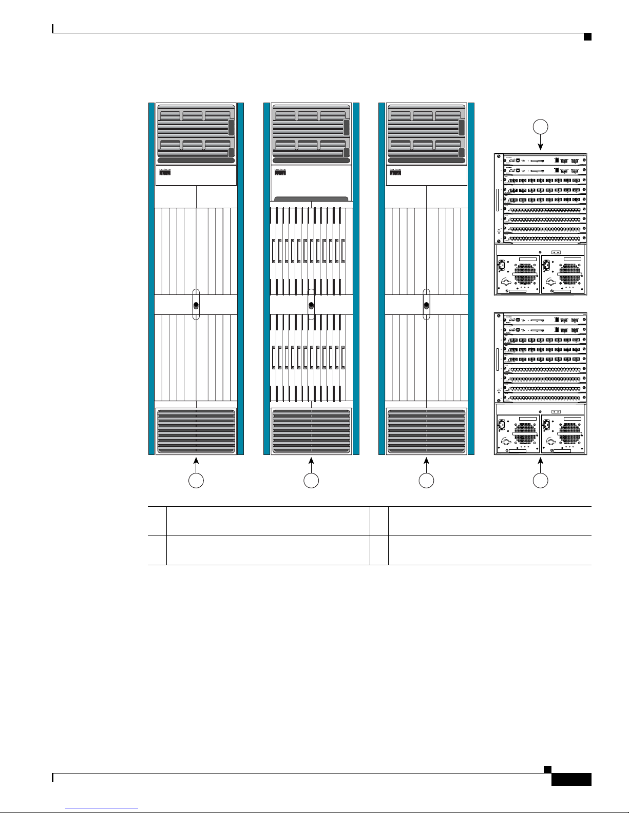
Figure 1-1 shows the single-FCC multishelf system, Figure 1-2 shows the two-FCC multishelf system,
and Figure 1-3 shows the four-FCC multishelf system.
Page 19
1-3
Cisco IOS XR Getting Started Guide
OL-10957-02
Chapter 1 Introduction to Cisco IOS XR Software
Cisco CRS-1 Multishelf System Overview
Figure 1-1 Single-FCC Multishelf System
1 Cisco CRS-1 16-Slot Line Card Chassis (two
required)
3 Cisco Catalyst 6509 Switch (two suggested)
2 Cisco CRS-1 Fabric Card Chassis (one
required)
OUTPUT
FAIL
FANOKINPUT
OK
OUTPUT
FAIL
FANOKINPUT
OK
OUTPUT
FAIL
FANOKINPUT
OK
OUTPUT
FAIL
FANOKINPUT
OK
129492
1 2 1 3
3
Page 20
1-4
Cisco IOS XR Getting Started Guide
OL-10957-02
Chapter 1 Introduction to Cisco IOS XR Software
Cisco CRS-1 Multishelf System Overview
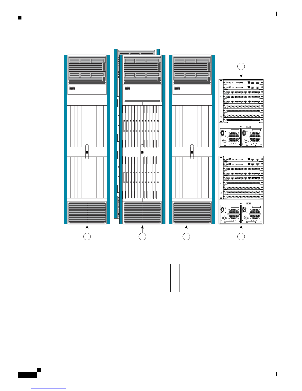
Figure 1-2 Two-FCC Multishelf System
1 Cisco CRS-1 16-Slot Line Card Chassis (two
required)
3 Cisco Catalyst 6509 Switch (two suggested)
2 Cisco CRS-1 Fabric Card Chassis (two
required)
OUTPUT
FAIL
FANOKINPUT
OK
OUTPUT
FAIL
FANOKINPUT
OK
OUTPUT
FAIL
FANOKINPUT
OK
OUTPUT
FAIL
FANOKINPUT
OK
158260
1 2 1 3
3
Page 21
1-5
Cisco IOS XR Getting Started Guide
OL-10957-02
Chapter 1 Introduction to Cisco IOS XR Software
Cisco CRS-1 Multishelf System Overview
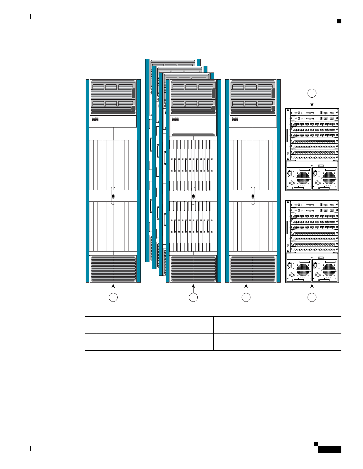
Figure 1-3 Four-FCC Multishelf System
For more information on multishelf systems, see Chapter 3, “Bringing Up the Cisco IOS XR Software
on a Multishelf System.”
1 Cisco CRS-1 16-Slot Line Card Chassis (two
required)
3 Cisco Catalyst 6509 Switch (two suggested)
2 Cisco CRS-1 Fabric Card Chassis (four
required)
OUTPUT
FAIL
FANOKINPUT
OK
OUTPUT
FAIL
FANOKINPUT
OK
OUTPUT
FAIL
FANOKINPUT
OK
OUTPUT
FAIL
FANOKINPUT
OK
149632
1 2 1 3
3
Page 22

1-6
Cisco IOS XR Getting Started Guide
OL-10957-02
Chapter 1 Introduction to Cisco IOS XR Software
Router Management Interfaces
Router Management Interfaces
Because new routers are not yet configured for your environment, you must start configuration using the
command-line interface (CLI). This guide provides instructions on using the CLI to configure basic
router features. The Cisco IOS XR software supports the following router management interfaces, which
are described in the following sections:
• Command-Line Interface, page 1-6
• Craft Works Interface, page 1-6
• Extensible Markup Language API, page 1-6
• Simple Network Management Protocol, page 1-7
Command-Line Interface
The CLI is the primary user interface for configuring, monitoring, and maintaining routers that run the
Cisco IOS XR software. The CLI allows you to directly and simply execute Cisco IOS XR commands.
All procedures in this guide use the CLI. Before you can use other router management interfaces, you
must first use the CLI to install and configure those interfaces. Guidelines for using the CLI are
presented in the following chapters:
• Chapter 4, “Configuring General Router Features”
• Chapter 5, “Configuring Additional Router Features”
• Chapter 6, “CLI Tips, Techniques, and Shortcuts”
For information on CLI procedures for other tasks, such as hardware interface and software protocol
management, see the Cisco IOS XR software documents listed in the “Related Documents” section on
page x.
Craft Works Interface
The Craft Works Interface (CWI) is a client-side application used to configure and manage routers that
run the Cisco IOS XR software. CWI includes advanced CLI features and a graphical user interface, and
it is included with the Cisco IOS XR Manageability package.
The CWI is a desktop used to launch management and configuration applications. The management and
configuration features include fault management, configuration management, performance management,
security management, and inventory management, with an emphasis on speed and efficiency. For more
information, see the Cisco IOS XR software documents listed in the “Related Documents” section on
page x.
Extensible Markup Language API
The Extensible Markup Language (XML) application programming interface (API) is an XML interface
used for rapid development of client applications and perl scripts to manage and monitor the router.
Client applications can be used to configure the router or request status information from the router by
encoding a request in XML API tags and sending it to the router. The router processes the request and
Page 23

1-7
Cisco IOS XR Getting Started Guide
OL-10957-02
Chapter 1 Introduction to Cisco IOS XR Software
Selecting and Identifying the Designated Shelf Controller
sends the response to the client in the form of encoded XML API tags. The XML API supports readily
available transport layers, including Telnet, Secure Shell (SSH), and Common Object Request Broker
Architecture (CORBA). The Secure Socket Layer (SSL) transport is also supported by the XML API.
For more information, see the Cisco IOS XR software documents listed in the “Related Documents”
section on page x.
Simple Network Management Protocol
Simple Network Management Protocol (SNMP) is an application-layer protocol designed to facilitate
the exchange of management information between network devices. By using SNMP-transported data
(such as packets per second and network error rates), network administrators can more easily manage
network performance, find and solve network problems, and plan for network growth.
The Cisco IOS XR software supports SNMP v1, v2c, and v3. SNMP is part of a larger architecture called
the Internet Network Management Framework (NMF), which is defined in Internet documents called
RFCs. The SNMPv1 NMF is defined by RFCs 1155, 1157, and 1212, and the SNMPv2 NMF is defined
by RFCs 1441 through 1452.
SNMP is a popular protocol for managing diverse commercial internetworks and those used in
universities and research organizations. SNMP-related standardization activity continues even as
vendors develop and release state-of-the-art, SNMP-based management applications. SNMP is a
relatively simple protocol, yet its feature set is sufficiently powerful to handle the difficult problems
presented in trying to manage the heterogeneous networks of today.
For more information, see the Cisco IOS XR software documents listed in the “Related Documents”
section on page x.
Selecting and Identifying the Designated Shelf Controller
The designated shelf controller (DSC) controls a standalone router or a multishelf System. A DSC is a
role that is assigned to one route processor (RP) card or performance route processor (PRP) card in each
router or multishelf system. RP cards operate in Cisco CRS-1 routers, and PRP cards operate in
Cisco XR 12000 and 12000 Series routers.
Note Throughout this guide, the term RP is used to refer to the RP cards supported on Cisco CRS-1 routers
and the PRP cards supported on Cisco XR 12000 Series Routers. If a feature or an issue applies to only
one platform, the accompanying text specifies the platform.
Although each router or multishelf system can have multiple RP cards, only one can serve as the DSC
and control the router or multishelf system. The DSC provides system-wide administrative functions,
including:
• User configuration using a terminal connection or network connection
• Distribution of software to each node in the router or system
• Coordination of software versioning and configurations for all nodes in the router or system
• Hardware inventory and environmental monitoring
The first step in setting up a new router is to select or identify the DSC because the initial router
configuration takes place through the DSC. The following sections describe how to select and identify
the DSC on different routers and the multishelf system:
Page 24

1-8
Cisco IOS XR Getting Started Guide
OL-10957-02
Chapter 1 Introduction to Cisco IOS XR Software
Selecting and Identifying the Designated Shelf Controller
• Selecting and Identifying the DSC on Cisco CRS-1 Routers, page 1-8
• Selecting and Identifying the DSC on Cisco CRS-1 Multishelf Systems, page 1-8
• Selecting and Identifying the DSC on Cisco XR 12000 and 12000 Series Routers, page 1-9
Selecting and Identifying the DSC on Cisco CRS-1 Routers
A Cisco CRS-1 router supports up to two RPs. If only one RP is installed, that RP automatically becomes
the DSC. If two RPs are installed, the default configuration selects RP0 as the DSC. To select RP1 to
become the DSC for a new installation, install RP1 first, apply power to the system, and wait for RP1 to
start up. When the Primary LED on the RP1 front panel lights, RP1 is operating as the DSC, and you can
install RP0.
Tip After the router starts for the first time, you can use the redundancy reddrv command to select which
RP becomes the DSC during a restart.
The active RP and DSC lights the Primary LED on the RP front panel. The alphanumeric LED display
on the active RP displays ACTV RP. By default, the other RP becomes the standby RP, displays STBY
RP on the alphanumeric display, and takes over if the DSC fails.
To visually determine which RP is operating as the DSC in a Cisco CRS-1 router, look for the RP on
which the Primary LED is lit. You can also look for the RP that displays the ACTV RP message on the
alphanumeric display.
Selecting and Identifying the DSC on Cisco CRS-1 Multishelf Systems
A Cisco CRS-1 Multishelf System supports up to two RPs in each LCC. Each LCC must have at least
one RP, so a multishelf system supports between two and four RPs. The RPs in a multishelf system
operate much like the RPs in a standalone router. The difference is that only one LCC can host the DSC.
During the initial startup of a multishelf system, the DSC is RP0 in the LCC with the lowest configured
rack number, which is usually Rack 0. If you want to select RP1 within Rack 0 to become the DSC,
install RP1 first, and wait for RP1 to start up. When the Primary LED on the RP1 front panel lights (or
the alphanumeric display shows ACTV RP), RP1 is operating as the DSC, and you can install RP0. If
you are setting up a new multishelf system, the instructions in Chapter 3, “Bringing Up the Cisco IOS
XR Software on a Multishelf System,” specify the appropriate time to bring up and configure the DSC.
Tip After the router starts for the first time, you can use the redundancy reddrv command to select which
Rack 0 RP becomes the DSC during a restart.
The active RP and DSC lights the Primary LED on the RP front panel. The alphanumeric LED display
on the active RP displays ACTV RP. By default, the other RP becomes the standby RP, displays STBY
RP on the alphanumeric display, and takes over if the DSC fails.
After the DSC starts up in Rack 0, the DSC remains in Rack 0 while at least one RP in Rack 0 is operating
properly. If both RPs in Rack 0 fail, the active RP in the other rack becomes the DSC. The process of
moving the DSC function from one rack to another is called DSC migration. For more information on
DSC migration, see the Cisco IOS XR System Management Configuration Guide, Release 3.4.
Page 25

1-9
Cisco IOS XR Getting Started Guide
OL-10957-02
Chapter 1 Introduction to Cisco IOS XR Software
Connecting to the Router Through the Console Port
Note Any LCC can host the DSC. The FCC cannot host the DSC function.
Selecting and Identifying the DSC on Cisco XR 12000 and 12000 Series Routers
A Cisco XR 12000 or 12000 Series router supports multiple PRPs. When the router is started for the first
time, the PRP in the lowest-numbered slot becomes the active PRP and is identified by the alphanumeric
display: ACTV RP. The active PRP serves as the DSC. If another PRP is configured as a standby PRP
for the DSC, that PRP can assume the DSC role if the DSC fails.
To have a PRP in a higher-numbered slot become the DSC, you must bring up the router with only that
PRP installed. After the chosen PRP becomes the DSC, it remains the DSC after subsequent restarts and
you can add the other PRPs.
Note Additional PRPs can be installed to host secure domain routers (SDRs), which are introduced in
Chapter 4, “Configuring General Router Features.” To configure general router features, you must
connect to the DSC. To configure SDR features, you must connect to the PRP for the appropriate SDR.
Connecting to the Router Through the Console Port
The first time you connect to a new router with Cisco IOS XR software, you must connect through the
Console port on the DSC. Although typical router configuration and management take place using an
Ethernet port on the DSC, this port must be configured for your local area network before it can be used.
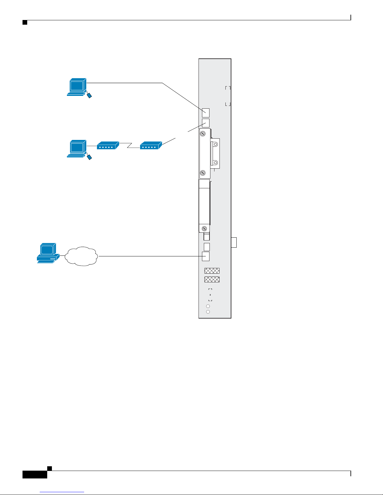
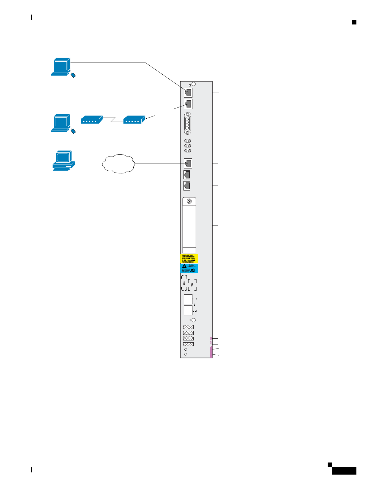
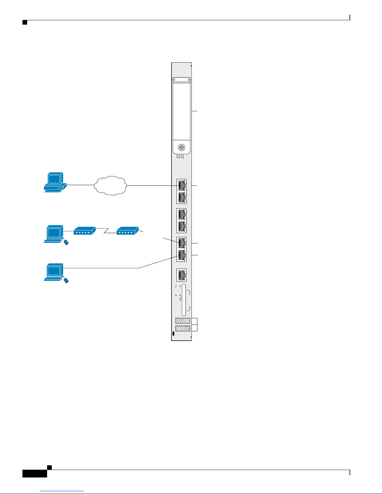
Figure 1-4 shows the RP connections on the Cisco CRS-1 16-Slot Line Card Chassis, and Figure 1-5
shows the RP connections on the Cisco CRS-1 4-Slot Line Card Chassis and Cisco CRS-1 8-Slot Line
Card Chassis. Figure 1-6 shows the PRP-2 connections on the Cisco XR 12000 Series Router.
Note Cisco IOS XR software does not support the PRP-1.
Page 26
1-10
Cisco IOS XR Getting Started Guide
OL-10957-02
Chapter 1 Introduction to Cisco IOS XR Software
Connecting to the Router Through the Console Port
Figure 1-4 Communication Ports on the RP for a Cisco CRS-1 16-Slot LCC
Console
AUX
PC Card
(disk1:)
MGMT ETH
CNTL ETH 1
CNTL ETH 0
Primary
Status
HDD
RP
Local terminal or
terminal server for
CLI communication
Remote terminal for
CLI communication
RJ-45 cable
Remote CLI, CWI,
XML, or SNMP
communication
RJ-45 cable
Optical Gigabit Ethernet for control
plane: (not user configurable)
116547
Network
Management Ethernet connection
for out-of-band network communciation
Page 27
1-11
Cisco IOS XR Getting Started Guide
OL-10957-02
Chapter 1 Introduction to Cisco IOS XR Software
Connecting to the Router Through the Console Port
Figure 1-5 Communication Ports on the RP for Cisco CRS-1 4-slot and 8-Slot LCCs
Primary
Status
Console
AUX
CRITICAL
MAJOR
MINOR
149693
Optical Gigabit Ethernet for control
plane: (not user configurable)
Terminal connection
Modem connection
Primary RP (on=primary)
Card status (green=OK)
User-removable flash disk1
stores installation PIE files
A second internal flash disk0
stores installed software and
active configurations
Management Ethernet connection
for out-of-band network communication
LED status
displays
(alphanumeric)
ALARM
PID/VID
MGMT
ETH
CNTL
ETH 0
PC
CARD
CNTL
ETH 1
EXT
CLK 1
EXT
CLK 2
Remote terminal for
CLI communication
RJ-45 cable
Local terminal or
terminal server for
CLI communication
RJ-45 cable
Remote CLI, CWI, XML,
or SNMP communication.
Remote file storage
Ethernet cable
Network
Page 28
1-12
Cisco IOS XR Getting Started Guide
OL-10957-02
Chapter 1 Introduction to Cisco IOS XR Software
Connecting to the Router Through the Console Port
Figure 1-6 Communication Ports on the PRP-2 for a Cisco XR 12000 Series Router
To connect to the router, perform the following procedure.
SUMMARY STEPS
1. Power on the standalone router, or power on Rack 0 in a multishelf system.
2. Identify the DSC.
3. Connect a terminal to the Console port of the DSC.
4. Start the terminal emulation program.
5. Press Enter.
ACT
SIG
ACT
SIG
SLOT-1
SLOT-0
CONSOLE ETH 2AUX
RESET
PERFORMANCE ROUTE PROCESSOR 2
BITS 1BITS 0
DATA
LINK
DATA
LINK
ETH 1ETH 0
149695
Terminal connection
Modem connection
User-removable flash disk1
stores installation PIE files
A second internal flash disk0
stores installed software and
active configurations
LED status
displays
(alphanumeric)
Remote CLI, CWI, XML,
or SNMP communication.
Remote file storage
Ethernet cable
Network
Local terminal or
terminal server for
CLI communication
RJ-45 cable
Remote terminal for
CLI communication
RJ-45 cable
Management Ethernet connection for
out-of-band network communication
Page 29

1-13
Cisco IOS XR Getting Started Guide
OL-10957-02
Chapter 1 Introduction to Cisco IOS XR Software
Connecting to the Router Through the Console Port
6. Log in to the router.
DETAILED STEPS
Command or Action Purpose
Step 1
Power on the standalone router, or power on Rack 0 in
a multishelf system.
Starts the router or Rack 0.
• This step is required only if the power is not on.
• For information on power installation and controls, see
the hardware documentation listed in the “Related
Documents” section on page x.
Step 2
Identify the DSC. Identifies the RP to which you must connect in the next step.
• For more information, see the “Selecting and
Identifying the Designated Shelf Controller” section on
page 1-7.
Step 3
Connect a terminal to the Console port of the DSC. Establishes a communications path to the router.
• During the initial setup, you can communicate with the
router only through the Console port of the DSC.
• The router Console port is designed for a serial cable
connection to a terminal or a computer that is running a
terminal emulation program.
• The terminal settings are:
–
Bits per second: 9600/9600
–
Data bits: 8
–
Parity: None
–
Stop bit: 2
–
Flow control: None
• For information on the cable requirements for the
Console port, see the hardware documentation listed in
the “Related Documents” section on page x.
Step 4
Start the terminal emulation program. (Optional.) Prepares a computer for router communications.
• The step is not required if you are connecting through a
terminal.
• Terminals send keystrokes to and receive characters
from another device. If you connect a computer to the
Console port, you must use a terminal emulation
program to communicate with the router. For
instructions on using the terminal emulation program,
see the documentation for that program.
Page 30

1-14
Cisco IOS XR Getting Started Guide
OL-10957-02
Chapter 1 Introduction to Cisco IOS XR Software
Where to Go Next
Where to Go Next
If you have logged into the router or multishelf system, you are ready to perform general router
configuration as described in Chapter 4, “Configuring General Router Features.”
If the router is prompting you to enter a root-system username, bring up the router or multishelf system
as described in the appropriate chapter:
• Chapter 2, “Bringing Up the Cisco IOS XR Software on a Standalone Router”
• Chapter 3, “Bringing Up the Cisco IOS XR Software on a Multishelf System”
Step 5
Press Enter. Initiates communication with the router.
• If no text or router prompt appears when you connect to
the console port, press Enter to initiate
communications.
• If no text appears when you press Enter, give the router
more time to complete the initial boot procedure, then
press Enter.
• If the prompt gets lost among display messages, press
Enter again.
• If the router has no configuration, the router displays
the prompt:
Enter root-system username:
• If the router has been configured, the router displays the
prompt:
Username:
Step 6
Log in to the router. Establishes your access rights for the router management
session.
• Enter the root-system username and password or the
username and password provided by your system
administrator.
• After you log in, the router displays the CLI prompt,
which is described in the “CLI Prompt” section on
page 4-12.
• If the router prompts you to enter a root-system
username, the router is not configured, and you should
follow one of the bring up procedures mentioned in the
next section.
Command or Action Purpose
Page 31

CHA PTER
2-1
Cisco IOS XR Getting Started Guide
OL-10957-02
2
Bringing Up the Cisco IOS XR Software on a
Standalone Router
This chapter provides instructions for bringing up the Cisco IOS XR software on a standalone router for
the first time. This section applies to standalone routers that are delivered with Cisco IOS XR software
installed.
Note If you are upgrading a Cisco XR 12000 Series Router from Cisco IOS software to
Cisco IOS XR software, see the Cisco IOS XR software document titled Upgrading from Cisco IOS to
Cisco IOS XR Software on the Cisco 12000 Series Router.
Contents
This chapter contains the following sections:
• Prerequisites, page 2-1
• Bringing Up and Configuring a Standalone Router, page 2-2
• Verifying the System After Initial Bring-Up, page 2-4
• Where to Go Next, page 2-8
Prerequisites
The following sections describe the software and hardware requirements for bringing up a standalone
system.
Software Requirements
The system requires the following software:
• Cisco IOS XR Software Release 3.4.0
• ROMMON 1.42 or later version on each RP in the system
Page 32

2-2
Cisco IOS XR Getting Started Guide
OL-10957-02
Chapter 2 Bringing Up the Cisco IOS XR Software on a Standalone Router
Bringing Up and Configuring a Standalone Router
Caution The ROM Monitor software must be upgraded to version 1.42 or a later version on all RPs before a
Cisco CRS-1 system is upgraded to Cisco IOS XR Software Release 3.4.0 or a later release. If the router
is brought up with an incompatible version of the ROM Monitor software, then the standby RP may fail
to boot. For instructions to overcome a boot block in the standby RP in a single-chassis system, see
Cisco IOS XR ROM Monitor Guide. If a boot block occurs in a multishelf system, contact your
Cisco Systems support representative for assistance. See Obtaining Technical Assistance, page xiv.
Hardware Prerequisites and Documentation
The Cisco IOS XR software runs on the routers listed in the “Supported Standalone System
Configurations” section on page 1-1. Before a router can be started, the following hardware management
procedures must be completed:
• Site preparation
• Equipment unpacking
• Router installation
For information on how to complete these procedures for your router equipment, see the hardware
documents listed in the “Related Documents” section on page x.
Note If you are upgrading a Cisco 12000 Series Router from Cisco IOS software to Cisco IOS XR software,
you must first prepare the router. Refer to Upgrading from Cisco IOS to Cisco IOS XR Software on the
Cisco 12000 Series Router for more information. See the “Related Documents” section on page x for a
complete listing of available documents.
Bringing Up and Configuring a Standalone Router
To bring up a standalone router, you need to connect to the router and configure root-system username
and password as described in the following procedure:
SUMMARY STEPS
1. Establish a connection to the DSC Console port.
2. Type the username for the root-system login and press Return.
3. Type the password for the root-system login and press Return.
4. Log in to the router.
Page 33

2-3
Cisco IOS XR Getting Started Guide
OL-10957-02
Chapter 2 Bringing Up the Cisco IOS XR Software on a Standalone Router
Bringing Up and Configuring a Standalone Router
DETAILED STEPS
Examples
The following example shows the root-system username and password configuration for a new router,
and it shows the initial log in:
--- Administrative User Dialog ---
Enter root-system username: cisco
Enter secret:
Enter secret again:
RP/0/0/CPU0:Jan 10 12:50:53.105 : exec[65652]: %MGBL-CONFIG-6-DB_COMMIT :
'Administration configuration committed by system'. Use 'show configuration
commit changes 2000000009' to view the changes.
Use the 'admin' mode 'configure' command to modify this configuration.
Command or Action Purpose
Step 1
Establish a connection to the DSC Console port. Initiates communication with the router.
• For instructions on connecting to the Console port, see
the “Connecting to the Router Through the Console
Port” section on page 1-9.
• If the router has been configured, the router displays the
prompt:
Username:
• If the Username prompt appears, skip this procedure
and continue general router configuration as described
in Chapter 4, “Configuring General Router Features.”
Step 2
Type the username for the root-system login and press
Return.
Sets the root-system username, which is used to log in to the
router.
Step 3
Type the password for the root-system login and press
Return.
Creates an encrypted password for the root-system
username.
Note This password can be changed with the secret
command.
Step 4
Retype the password for the root-system login and
press Return.
Allows the router to verify that you have entered the same
password both times.
• If the passwords do not match, the router prompts you
to repeat the process.
Step 5
Log in to the router. Establishes your access rights for the router management
session.
• Enter the root-system username and password that were
created earlier in this procedure.
• After you log in, the router displays the CLI prompt,
which is described in the “CLI Prompt” section on
page 4-12.
Page 34

2-4
Cisco IOS XR Getting Started Guide
OL-10957-02
Chapter 2 Bringing Up the Cisco IOS XR Software on a Standalone Router
Verifying the System After Initial Bring-Up
User Access Verification
Username: cisco
Password:
RP/0/0/CPU0:ios#
The secret line in the configuration command script shows that the password is encrypted. When you
enter the password during configuration and login, the password is hidden.
Verifying the System After Initial Bring-Up
To verify the status of the router, perform the following procedure:
SUMMARY STEPS
1. show version
2. admin
show platform [node-id]
end
3. show redundancy
4. show environment
DETAILED STEPS
Command or Action Purpose
Step 1
show version
Example:
RP/0/RP0/CPU0:router# show version
Displays information about the router, including image names,
uptime, and other system information.
Step 2
admin
show platform [
node-id
]
exit
Example:
RP/0/RP0/CPU0:router# admin
RP/0/RP0/CPU0:router(admin)# show platform
RP/0/RP0/CPU0:router(admin)# exit
Places the router in administration EXEC mode, displays
information about the status of cards and modules installed in
the router, and terminates administration EXEC mode.
• Some cards support a CPU module and service processor
(SP) module. Other cards support only a single module.
• A card module is also called a node. When a node is
working properly, the status of the node in the State column
is IOS XR RUN.
• Type the show platform node-id command to display
information for a specific node. Replace node-id with a
node name from the show platform command Node
column.
Note To view the status of all cards and modules, the show
platform command must be executed in administration
EXEC mode.
Page 35

2-5
Cisco IOS XR Getting Started Guide
OL-10957-02
Chapter 2 Bringing Up the Cisco IOS XR Software on a Standalone Router
Verifying the System After Initial Bring-Up
Examples of show Commands
The following sections provide examples of show commands:
• show version Command, page 2-5
• show environment Command, page 2-6
• show platform Command, page 2-7
• show redundancy Command, page 2-8
show version Command
To display basic information about the router configuration, type the show version command in EXEC
mode, as shown in the following example:
RP/0/RP0/CPU0:router# show version
Cisco IOS XR Software, Version 3.3.0[2I]
Copyright (c) 2006 by cisco Systems, Inc.
ROM: System Bootstrap, Version 1.38(20050525:193559) [CRS-1 ROMMON],
CRS-8_P1 uptime is 1 week, 1 day, 17 hours, 1 minute
System image file is "disk0:hfr-os-mbi-3.3.0/mbihfr-rp.vm"
cisco CRS-8/S (7457) processor with 4194304K bytes of memory.
7457 processor at 1197Mhz, Revision 1.2
16 Packet over SONET/SDH network interface(s)
16 SONET/SDH Port controller(s)
2 Ethernet/IEEE 802.3 interface(s)
16 GigabitEthernet/IEEE 802.3 interface(s)
2043k bytes of non-volatile configuration memory.
38079M bytes of hard disk.
1000592k bytes of ATA PCMCIA card at disk 0 (Sector size 512 bytes).
1000640k bytes of ATA PCMCIA card at disk 1 (Sector size 512 bytes).
Package active on node 0/1/SP:
hfr-diags, V 3.3.0[2I], Cisco Systems, at disk0:hfr-diags-3.3.0
Built on Mon Mar 13 12:58:02 UTC 2006
By iox8.cisco.com in /auto/ioxws48/production/3.3.0.2I/hfr/workspace for c8
hfr-admin, V 3.3.0[2I], Cisco Systems, at disk0:hfr-admin-3.3.0
Built on Mon Mar 13 11:46:36 UTC 2006
By iox8.cisco.com in /auto/ioxws48/production/3.3.0.2I/hfr/workspace for c8
Step 3
show redundancy
Example:
RP/0/RP0/CPU0:router# show redundancy
Displays the state of the primary (active) and standby (inactive)
RPs, including the ability of the standby to take control of the
system.
• If both RPs are working correctly, one node displays active
role, the Partner node row displays standby role, and the
Standby node row displays Ready.
Step 4
show environment
Example:
RP/0/RP0/CPU0:router# show environment
Displays information about the hardware attributes and status.
Command or Action Purpose
Page 36

2-6
Cisco IOS XR Getting Started Guide
OL-10957-02
Chapter 2 Bringing Up the Cisco IOS XR Software on a Standalone Router
Verifying the System After Initial Bring-Up
hfr-base, V 3.3.0[2I], Cisco Systems, at disk0:hfr-base-3.3.0
Built on Mon Mar 13 11:43:22 UTC 2006
By iox8.cisco.com in /auto/ioxws48/production/3.3.0.2I/hfr/workspace for c8
hfr-os-mbi, V 3.3.0[2I], Cisco Systems, at disk0:hfr-os-mbi-3.3.0
Built on Mon Mar 13 11:27:02 UTC 2006
By iox8.cisco.com in /auto/ioxws48/production/3.3.0.2I/hfr/workspace for c8
--More--
show environment Command
To display environmental monitor parameters for the system, use the show environment command in
EXEC or administration EXEC mode. The following command syntax is used:
show environment [options]
Enter the show environment ? command to display the command options.
In the following example, temperature information for a Cisco CRS-1 router is shown:
RP/0/RP0/CPU0:router# show environment temperatures
R/S/I Modules Inlet Exhaust Hotspot
Temperature Temperature Temperature
(deg C) (deg C) (deg C)
0/1/*
host 32, 30 26, 27 35
cpu 34
fabricq0 27
fabricq1 32
ingressq 37
egressq 32 27
ingresspse 35
egresspse 29
jacket 25 24 25
spa0 19 25, 32
spa5 25 24
0/6/*
host 32, 26 27, 25 33
cpu 35
fabricq0 27
fabricq1 32
ingressq 37
egressq 30 25
ingresspse 31
egresspse 29
jacket 24 25 26
spa0 19 25, 31
spa4 22 33, 35
spa5 24 24
0/RP0/*
host 23 24 24, 33, 26,
24, 27
0/RP1/*
host 23 24 24, 32, 26,
24, 26
In the following example, LED status of the nodes in a Cisco CRS-1 router is shown:
RP/0/RP0/CPU0:router# show environment leds
Page 37

2-7
Cisco IOS XR Getting Started Guide
OL-10957-02
Chapter 2 Bringing Up the Cisco IOS XR Software on a Standalone Router
Verifying the System After Initial Bring-Up
0/1/*: Module (host) LED status says: OK
0/1/*: Module (jacket) LED status says: OK
0/1/*: Module (spa0) LED status says: OK
0/1/*: Module (spa5) LED status says: OK
0/6/*: Module (host) LED status says: OK
0/6/*: Module (jacket) LED status says: OK
0/6/*: Module (spa0) LED status says: OK
0/6/*: Module (spa4) LED status says: OK
0/6/*: Module (spa5) LED status says: OK
0/RP0/*: Module (host) LED status says: OK
0/RP0/*: Alarm LED status says: NONE
0/RP1/*: Module (host) LED status says: OK
0/RP1/*: Alarm LED status says: NONE
See the Cisco IOS XR Interface and Hardware Component Command Reference for more information.
show platform Command
The show platform command displays information on router resources. In EXEC mode, the show
platform command displays the resources assigned to the secure domain router (SDR) you are
managing. In administration EXEC mode, the show platform command displays all router resources.
Note SDRs are introduced in Chapter 4, “Configuring General Router Features.”
The following EXEC mode sample output displays the nodes assigned to the default SDR, which is
called the owner SDR:
RP/0/RP0/CPU0:router# show platform
Node Type PLIM State Config State
----------------------------------------------------------------------------0/1/CPU0 MSC Jacket Card IOS XR RUN PWR,NSHUT,MON
0/1/0 MSC(SPA) 4XOC3-POS OK PWR,NSHUT,MON
0/1/5 MSC(SPA) 8X1GE OK PWR,NSHUT,MON
0/6/CPU0 MSC Jacket Card IOS XR RUN PWR,NSHUT,MON
0/6/0 MSC(SPA) 4XOC3-POS OK PWR,NSHUT,MON
0/6/4 MSC(SPA) 8XOC3/OC12-POS OK PWR,NSHUT,MON
0/6/5 MSC(SPA) 8X1GE OK PWR,NSHUT,MON
0/RP0/CPU0 RP(Active) N/A IOS XR RUN PWR,NSHUT,MON
0/RP1/CPU0 RP(Standby) N/A IOS XR RUN PWR,NSHUT,MON
The following administration EXEC mode sample output displays all router nodes:
RP/0/RP0/CPU0:router# admin
RP/0/RP0/CPU0:router(admin)# show platform
Node Type PLIM State Config State
----------------------------------------------------------------------------0/1/SP MSC(SP) N/A IOS XR RUN PWR,NSHUT,MON
0/1/CPU0 MSC Jacket Card IOS XR RUN PWR,NSHUT,MON
0/1/0 MSC(SPA) 4XOC3-POS OK PWR,NSHUT,MON
0/1/5 MSC(SPA) 8X1GE OK PWR,NSHUT,MON
0/6/SP MSC(SP) N/A IOS XR RUN PWR,NSHUT,MON
0/6/CPU0 MSC Jacket Card IOS XR RUN PWR,NSHUT,MON
0/6/0 MSC(SPA) 4XOC3-POS OK PWR,NSHUT,MON
0/6/4 MSC(SPA) 8XOC3/OC12-POS OK PWR,NSHUT,MON
0/6/5 MSC(SPA) 8X1GE OK PWR,NSHUT,MON
0/RP0/CPU0 RP(Active) N/A IOS XR RUN PWR,NSHUT,MON
0/RP1/CPU0 RP(Standby) N/A IOS XR RUN PWR,NSHUT,MON
0/SM0/SP FC/S(SP) N/A IOS XR RUN PWR,NSHUT,MON
0/SM1/SP FC/S(SP) N/A IOS XR RUN PWR,NSHUT,MON
Page 38

2-8
Cisco IOS XR Getting Started Guide
OL-10957-02
Chapter 2 Bringing Up the Cisco IOS XR Software on a Standalone Router
Where to Go Next
0/SM2/SP FC/S(SP) N/A IOS XR RUN PWR,NSHUT,MON
0/SM3/SP FC/S(SP) N/A IOS XR RUN PWR,NSHUT,MON
RP/0/RP0/CPU0:router# end
Note Line cards in Cisco CRS-1 routers are called modular services cards (MSCs). The show platform
command output is different for Cisco CRS-1 routers and Cisco XR 12000 Series Routers.
In the following example, information is shown for a single node in a Cisco CRS-1 router:
RP/0/RP0/CPU0:router# show platform 0/1/CPU0
Node Type PLIM State Config State
----------------------------------------------------------------------------0/1/CPU0 MSC Jacket Card IOS XR RUN PWR,NSHUT,MON
For more information on node IDs, see the Cisco IOS XR System Management Configuration Guide,
Release 3.4.
For more information on the show platform command, see the Cisco IOS XR Interface and Hardware
Component Command Reference.
show redundancy Command
To display information about the active and standby (inactive) RPs, enter the show redundancy
command as follows:
RP/0/RP0/CPU0:router# show redundancy
Redundancy information for node 0/RP0/CPU0:
==========================================
Node 0/RP0/CPU0 is in ACTIVE role
Partner node (0/RP1/CPU0) is in STANDBY role
Standby node in 0/RP1/CPU0 is ready
Reload and boot info
---------------------RP reloaded Wed Feb 15 13:58:32 2006: 1 week, 6 days, 22 hours, 49 minutes ago
Active node booted Wed Feb 15 13:58:32 2006: 1 week, 6 days, 22 hours, 49 minuto
Standby node boot Wed Feb 15 13:59:00 2006: 1 week, 6 days, 22 hours, 49 minuteo
Standby node last went not ready Wed Mar 1 07:40:00 2006: 5 hours, 8 minutes ao
Standby node last went ready Wed Mar 1 07:40:00 2006: 5 hours, 8 minutes ago
There have been 0 switch-overs since reload
Where to Go Next
For information on configuring basic router features, see Chapter 4, “Configuring General Router
Features.”
Page 39

CHA PTER
3-1
Cisco IOS XR Getting Started Guide
OL-10957-02
3
Bringing Up the Cisco IOS XR Software on a
Multishelf System
This chapter describes how to bring up the Cisco IOS XR software on a Cisco CRS-1 Carrier Routing
System Multishelf System for the first time.
Contents
This chapter contains the following sections:
• Prerequisites, page 3-1
• Restrictions, page 3-2
• Information About Bringing Up a Multishelf System, page 3-3
• Configuring the External Cisco Catalyst 6509 Switches, page 3-8
• Integrated Switch System, page 3-20
• Bringing Up and Configuring Rack 0, page 3-28
• Bringing Up and Verifying FCCs, page 3-34
• Bringing Up and Verifying the Non-DSC LCC, page 3-37
• Verifying the Spanning Tree, page 3-39
• Verifying Fabric Cabling Connections, page 3-43
• Where to Go Next, page 3-47
Prerequisites
The following sections describe the software and hardware requirements for bringing up a multishelf
system.
Software Requirements
The multishelf system requires the following software:
• Cisco IOS XR Software Release 3.4
Page 40

3-2
Cisco IOS XR Getting Started Guide
OL-10957-02
Chapter 3 Bringing Up the Cisco IOS XR Software on a Multishelf System
Restrictions
• ROMMON 1.40 or higher on each RP in the system
Caution The ROM Monitor software must be upgraded to version 1.42 or a later version on all RPs before a
Cisco CRS-1 system is upgraded to Cisco IOS XR Software Release 3.4.0 or a later release. If the router
is brought up with an incompatible version of the ROM Monitor software, then the standby RP may fail
to boot. For instructions to overcome a boot block in the standby RP in a single-chassis system, see
Cisco IOS XR ROM Monitor Guide. If a boot block occurs in a multishelf system, contact your
Cisco Systems support representative for assistance. See Obtaining Technical Assistance, page xiv.
In addition, Cisco CRS-1 multishelf systems should be upgraded to ROMMON release 1.40 before being
upgraded to Cisco IOS XR Release 3.4.0 to ensure that RPs are assigned the correct rack numbers during
system boot.
For more information, see Cisco IOS XR ROM Monitor Guide.
Hardware Requirements
Before you can bring up a multishelf system, the system components must be physically installed and
tested. Three multishelf system configurations are supported, and they require the following
components:
• Two 16-slot line card chassis containing eight FC/M (S13) fabric cards
• Two external Gigabit Ethernet Cisco Catalyst 6509 switches
Single-FCC systems require one FCC containing eight SFC (S2) fabric cards. Two-FCC systems require
two FCCs, and four-FCC systems require four FCCs. In two- and four-FCC configurations, the eight
SFC (S2) fabric cards are distributed equally in the FCCs.
For instructions to install, cable, and verify a multishelf system, see the documents listed on the
Cisco CRS-1 documentation web page listed in the “Related Documents” section on page x.
Restrictions
The following restrictions apply to multishelf systems in Cisco IOS XR Software Release 3.4.0.
• The multishelf system supports:
–
Two 16-slot line card chassis.
–
One, two, or four FCCs.
–
Two external Catalyst switches to form a control Ethernet plane used for administrative
management and monitoring of the system.
• The 4-slot and 8-slot LCCs are not supported.
• Although Cisco IOS XR Software Release 3.4.0 supports the addition of a second line card chassis,
the removal of a line card chassis is restricted. Consult your Cisco Systems support representative
for more information (see the “Obtaining Technical Assistance” section on page xiv).
Page 41

3-3
Cisco IOS XR Getting Started Guide
OL-10957-02
Chapter 3 Bringing Up the Cisco IOS XR Software on a Multishelf System
Information About Bringing Up a Multishelf System
Information About Bringing Up a Multishelf System
The following sections provide information that is good to know before you bring up a multishelf
system:
• Bringup Overview, page 3-3
• Preparing a Rack Number Plan, page 3-3
Bringup Overview
The bringup procedure for a multishelf system starts after the hardware installation is complete. The
bringup procedure tasks configure the system components to work together and verify the operation and
configuration of system components. To bring up the multishelf system, complete the following
procedures in the sequence shown:
1. Configuring the External Cisco Catalyst 6509 Switches, page 3-8
2. Bringing Up and Configuring Rack 0, page 3-28
3. Bringing Up and Verifying FCCs, page 3-34
4. Bringing Up and Verifying the Non-DSC LCC, page 3-37
5. Verifying the Spanning Tree, page 3-39
During the bringup procedure, you need the information presented in the following section.
Preparing a Rack Number Plan
In a multishelf system, each chassis must be assigned a unique rack number, as shown in Figure 3-1. This
rack number is used to identify a chassis in the system, and maintain the software and configurations for
the chassis.
Caution Failure to assign a unique rack number to each chassis in the system can result in serious system error
and potential downtime. Unique rack numbers must be assigned and committed on Rack 0 before the
additional chassis are powered on and brought on line.
Page 42

3-4
Cisco IOS XR Getting Started Guide
OL-10957-02
Chapter 3 Bringing Up the Cisco IOS XR Software on a Multishelf System
Information About Bringing Up a Multishelf System
Figure 3-1 DSC in a CRS-1/M-F1 Multishelf System
Note Chassis, shelf, and rack are used interchangeably. Each term refers to the physical tower that contains
the installed cards, power, and cooling equipment. In general, chassis describes the system components.
Rack is used in software to assign a rack number to each chassis.
A rack number plan lists each chassis in a system with the correct chassis serial ID and an assigned rack
number. The serial ID is the chassis serial number, which can be accessed by the software and uniquely
identifies the chassis. The rack number for an LCC is a number in the range of 0 to 255, which is easier
to remember and read than serial numbers in display messages.
The rack number plan is used during the startup and configuration of Rack 0. The LCC that hosts the
DSC must be configured as Rack 0. The non-DSC LCC must be configured to use a rack number in the
range of 1 to 255. FCC rack numbers range from F0 to F3, as shown in Ta ble 3-1, Tab le 3- 2, and
Table 3-3.
Table 3-1 shows a sample rack number plan for a single-FCC system.
Table 3-1 Sample Rack Number Plan for a Single-FCC Multishelf System
Table 3-2 shows a sample rack number plan for a two-FCC system.
OUTPUT
FAIL
FANOKINPUTOKOUTPUT
FAIL
FANOKINPUT
OK
138118
Gigabit Ethernet Control Bus
OUTPUT
FAIL
FANOKINPUTOKOUTPUT
FAIL
FANOKINPUT
OK
SC
Fabric Cards
SC
Fabric Cards
Line Card Chassis
Rack 1
Line Card Chassis
Rack 0
Fabric Card Chassis
Rack F0
SM1
SM2
SM3
SM0
SM7
SM4
OIM22
OIM21
OIM15
OIM13
OIM12
OIM14
OIM23
OIM-LED 1
OIM16
RP (SC)
RP (SC)
OIM22
OIM21
OIM15
OIM13
OIM12
OIM14
OIM23
OIM-LED 1
OIM16
SM1
SM2
SM3
SM0
SM7
SM4
OIM22
OIM21
OIM15
OIM13
OIM12
OIM14
OIM23
OIM-LED 1
OIM16
RP (SC)
RP (SC)
OIM22
OIM21
OIM15
OIM13
OIM12
OIM14
OIM23
OIM-LED 1
OIM16
DSC
Catalyst 6509 Switches
Chassis Serial ID Rack Number
LCC containing the active DSC 0
Non-DSC LCC 1
Fabric chassis F0
Page 43

3-5
Cisco IOS XR Getting Started Guide
OL-10957-02
Chapter 3 Bringing Up the Cisco IOS XR Software on a Multishelf System
Information About Bringing Up a Multishelf System
Table 3-2 Sample Rack Number Plan for a Two-FCC Multishelf System
Table 3-3 shows a sample rack number plan for a four-FCC system.
Table 3-3 Sample Rack Number Plan for a Four-FCC Multishelf System
To complete the rack number plan, change the rack number for the non-DSC LCC if you want, and record
the serial number for each chassis. The chassis serial number is attached to the back of the chassis, as
shown in Figure 3-2 and Figure 3-3.
Chassis Serial ID Rack Number
LCC containing the active DSC 0
Non-DSC LCC 1
Fabric chassis 0 F0
Fabric chassis 1 F1
Chassis Serial ID Rack Number
LCC containing the active DSC 0
Non-DSC LCC 1
Fabric chassis 0 F0
Fabric chassis 1 F1
Fabric chassis 2 F2
Fabric chassis 3 F3
Page 44

3-6
Cisco IOS XR Getting Started Guide
OL-10957-02
Chapter 3 Bringing Up the Cisco IOS XR Software on a Multishelf System
Information About Bringing Up a Multishelf System
Figure 3-2 Location of the Serial Number on a Fabric Card Chassis
SN: XXXNNNNXXXX
129761, 781-00375-01
1
2
3
4
5
6
7
8
9
1
0
1
1
1
2
1
2
3
4
5
6
7
8
9
1
0
1
1
1
2
1
2
3
4
5
6
7
8
9
1
0
1
1
1
2
1
2
3
4
5
6
7
8
9
1
0
1
1
1
2
1
2
3
4
5
6
7
8
9
1
0
1
1
1
2
1
2
3
4
5
6
7
8
9
1
0
1
1
1
2
1
2
3
4
5
6
7
8
9
1
0
1
1
1
2
1
2
3
4
5
6
7
8
9
1
0
1
1
1
2
1
2
3
4
5
6
7
8
9
1
0
1
1
1
2
1
2
3
4
5
6
7
8
9
1
0
1
1
1
2
1
2
3
4
5
6
7
8
9
1
0
1
1
1
2
1
2
3
4
5
6
7
8
9
1
0
1
1
1
2
1
2
3
4
5
6
7
8
9
1
0
1
1
1
2
1
2
3
4
5
6
7
8
9
1
0
1
1
1
2
1
2
3
4
5
6
7
8
9
1
0
1
1
1
2
1
2
3
4
5
6
7
8
9
1
0
1
1
1
2
1
2
3
4
5
6
7
8
9
1
0
1
1
1
2
1
2
3
4
5
6
7
8
9
1
0
1
1
1
2
Page 45

3-7
Cisco IOS XR Getting Started Guide
OL-10957-02
Chapter 3 Bringing Up the Cisco IOS XR Software on a Multishelf System
Information About Bringing Up a Multishelf System
Figure 3-3 Location of the Serial Number on a Line Card Chassis
Caution Always assign a rack number to each chassis in the system before the chassis is booted. If a chassis is
not assigned a rack number, or if the rack number conflicts with an existing chassis, it may not be
recognized by the system or cause other operational difficulties.
If you cannot locate or read the chassis serial number on a chassis, you can view the serial number stored
in software as described in the following documents:
• To display the chassis serial numbers in administration EXEC mode, see Cisco IOS XR System
Management Configuration Guide, Release 3.4.
116535
P
W
R
OK
F
L
T
AC
FA
I
L
C
B
T
RI
P
I
L
IM
O
T
P
W
R
O
K
FL
T
A
C
FA
IL
C
B
TR
IP
I
L
IM
O
T
PW
R
O
K
F
L
T
AC
F
A
I
L
C
B
T
R
IP
I
LI
M
O
T
P
W
R
O
K
F
L
T
AC
F
A
IL
CB
T
R
IP
I
L
I
M
O
T
P
W
R
O
K
F
L
T
AC
F
A
IL
CB
T
RI
P
I
L
IM
OT
PW
R
OK
F
LT
A
C
F
AI
L
CB
TR
I
P
I
L
IM
O
T
SN: AAANNNNXXXX
Page 46

3-8
Cisco IOS XR Getting Started Guide
OL-10957-02
Chapter 3 Bringing Up the Cisco IOS XR Software on a Multishelf System
Configuring the External Cisco Catalyst 6509 Switches
• To display the configured chassis serial numbers in administration EXEC mode, see Cisco IOS XR
System Management Configuration Guide, Release 3.4.
• To display the chassis serial numbers in ROM Monitor, see Cisco IOS XR ROM Monitor Guide.
See the “Bringing Up and Configuring Rack 0” section on page 3-28 for complete instructions to bring
up a new router and configure the rack numbers.
Configuring the External Cisco Catalyst 6509 Switches
The control Ethernet network is formed by interconnecting each RP and shelf controller Gigabit Ethernet
(SCGE) card in the system through two external Catalyst switches. (The SCGE card is the control card
in an FCC.) The Catalyst switches are also directly connected using one or more Gigabit Ethernet links
(see Figure 3-4).
These Catalyst switches must also be configured for operation with the Cisco CRS-1 multishelf router.
This section includes instructions to configure and verify the Catalyst switches using the Cisco IOS
software. For instructions to install and cable the Catalyst switches, see CRS-1 Multishelf System
Interconnection and Cabling Guide.
This section includes the following topics:
• Prerequisites, page 3-9
• Restrictions, page 3-10
• Before You Begin, page 3-10
• Information About the Catalyst Switch Configuration, page 3-11
• Configuring the Catalyst Switches, page 3-11
• Verifying the Catalyst Switch, page 3-18
Page 47

3-9
Cisco IOS XR Getting Started Guide
OL-10957-02
Chapter 3 Bringing Up the Cisco IOS XR Software on a Multishelf System
Configuring the External Cisco Catalyst 6509 Switches
Figure 3-4 Control Ethernet Network Connections in a Single-FCC System
Prerequisites
The following sections describe the software and hardware requirements for bringing up Catalyst 6509
switches in a multishelf system.
Software Requirements
Each Cisco Catalyst 6509 switch requires the same software:
• Cisco IOS Release 12.2(14r)S9 with SUP720 Supervisor Engine controller module
• System Bootstrap (ROMMON), Version 1.3 or later
• BOOTLDR: s72033_rp Software (s72033_rp-PSV-M), Version 12.2(17d)SXB7
Both switches should use the same software. The filename of the software is
72033-psv-mz.122-17d.SXB8.bin, and is available on CCO at:
http://www.cisco.com/kobayashi/sw-center/lan/cat6000.shtml
Hardware Requirements
• Two external Cisco Catalyst 6509 switches correctly cabled to the Cisco CRS-1 multishelf router.
Catalyst
Ethernet
Switch
Line Card
Chassis
138147
RP
RP
RP
RP
Fabric Card
Chassis
SCGE
SCGE
Line Card
Chassis
Catalyst
Ethernet
Switch
Page 48

3-10
Cisco IOS XR Getting Started Guide
OL-10957-02
Chapter 3 Bringing Up the Cisco IOS XR Software on a Multishelf System
Configuring the External Cisco Catalyst 6509 Switches
• The recommended hardware configuration for an AC-powered Cisco Catalyst 6509 system is shown
in the following table:
Restrictions
The following restrictions apply to Cisco Catalyst 6509 switches that are installed in a multishelf system:
• Both Catalyst switches must operate with the same Cisco IOS software release.
• The spanning tree implementation of Cisco CRS-1 control Ethernet assumes that all Catalyst switch
ports connected to the multishelf system are kept in VLAN 1.
• The Gigabit Interface Converter (GBIC) transceiver module used on the Catalyst switches must
match the SFP optic used on each RP and SCGE card in the system. The GBIC can be either LX/LH
or SX, but the same type must be used on both ends.
Note Both Catalyst switches must be dedicated for use with the multishelf system. The Catalyst switches
should not be used for any other purpose.
Before You Begin
Before you begin to bring up the Catalyst 6509 switches, consider the following:
• The Catalyst switches must be installed, including all cables properly connected between the
switches and the Cisco CRS-1 router.
• See the “Related Documents” section on page x for a hyperlink to documents on installing and
connecting the Catalyst switches.
• For additional information regarding Cisco IOS commands and usage, see the “Cisco IOS Software
Configuration” page at the following URL:
http://www.cisco.com/univercd/cc/td/doc/product/software/index.htm
Quantity Description Part
1 Catalyst 6509 Chassis, 9slot, 15RU, No Pow Supply, No Fan
Tray
WS-C6509
1 Cisco CAT6000-SUP720 IOS IP
(see Software Requirements for complete details).
S733Z-12217SXB
1 Catalyst 6500/Cisco 7600 Supervisor 720 Fabric MSFC3
PFC3B
WS-SUP720-3B
1 Catalyst 6500 Sup720 Compact Flash Mem 256MB MEM-C6K-CPTFL256M
1 Catalyst 6000 16-port Gig-Ethernet Mod. (Req. GBICs) WS-X6416-GBIC
8 1000BASE-LX/LH long haul GBIC (singlemode or
multimode)
WS-G5486
1 Catalyst 6509 High Speed Fan Tray WS-C6K-9SLOT-FAN2
2 Catalyst 6000 2500W AC Power Supply WS-CAC-2500W
2 Power Cord, 250Vac 16A, straight blade NEMA 6-20 plug, USCAB-AC-2500W-US1
Page 49

3-11
Cisco IOS XR Getting Started Guide
OL-10957-02
Chapter 3 Bringing Up the Cisco IOS XR Software on a Multishelf System
Configuring the External Cisco Catalyst 6509 Switches
Information About the Catalyst Switch Configuration
The configuration described in the following sections places all Catalyst ports in VLAN 1. The
configuration on the Catalyst switches is the same as the configuration on the Cisco CRS-1 router
internal Broadcom switches—they all participate in a Multiple Spanning Tree (MST) region with one
MST instance.
The Catalyst switches are made the root of the network by assigning them the highest priority. Because
there are two Catalyst switches, one is selected as the root-bridge device. Configure the primary Catalyst
switch with priority 0 to make the switch the root of the network. Configure the second Catalyst switch
with a number greater than 0 and less than 32768. If the primary Catalyst switch (priority 0) fails, the
second switch becomes the root of the network.
Configuring the Catalyst Switches
The Cisco IOS software configuration must be applied to both external Catalyst switches.
Note Configure the primary Catalyst switch with priority 0 to make the switch the root of the network.
Configure the second Catalyst switch with a number greater than 0 and less than 32768. If the primary
Catalyst switch (priority 0) fails, the second switch becomes the root of the network.
To configure the Catalyst 6509 switches, use the following procedure:
SUMMARY STEPS
1. configure
2. spanning-tree portfast default
3. spanning-tree mode mst
4. spanning-tree mst configuration
5. name mst_region
6. revision number
7. instance instance_id vlan range
8. end
9. spanning-tree mst hello-time seconds
10. spanning-tree mst forward-time seconds
11. spanning-tree mst max-age seconds
12. spanning-tree mst max-hops hops
13. spanning-tree mst instance_id priority priority
14. udld aggressive
15. udld message time interval
16. interface gigabitethernet slot/port
17. switchport
18. switchport mode access
Page 50

3-12
Cisco IOS XR Getting Started Guide
OL-10957-02
Chapter 3 Bringing Up the Cisco IOS XR Software on a Multishelf System
Configuring the External Cisco Catalyst 6509 Switches
19. switchport access vlan 1
20. end
21. Repeat Step 16 through Step 20 for all interfaces.
22. Repeat all steps for the second switch.
DETAILED STEPS
Command or Action Purpose
Step 1
configure
Example:
router# configure
Places the switch in global configuration mode.
Step 2
spanning-tree portfast default
Example:
router(config)# spanning-tree portfast default
Enables PortFast by default on all access ports.
Step 3
spanning-tree mode mst
Example:
router(config)# spanning-tree mode mst
Selects the MST mode for the Spanning Tree Protocol.
Step 4
spanning-tree mst configuration
Example:
router(config)# spanning-tree mst configuration
Places the router in spanning tree MST configuration
mode.
Step 5
name
mst_region
Example:
router(config-mst)# name STP_1
Defines a name for an MST region.
Step 6
revision
number
Example:
router(config-mst)# revision 1
Sets a revision number for the MST configuration.
• This number must be identical on both switches.
Step 7
instance
instance_id
vlan
range
Example:
router(config-mst)# instance 1 vlan 1
Maps the MST instance to a range of VLANs.
Step 8
end
Example:
router(config-mst)# end
Exits spanning tree MST configuration mode.
Step 9
spanning-tree mst hello-time
seconds
Example:
router(config)# spanning-tree mst hello-time 1
Sets the hello-time delay timer for all instances on the
switch.
• We recommend 1 second.
Page 51

3-13
Cisco IOS XR Getting Started Guide
OL-10957-02
Chapter 3 Bringing Up the Cisco IOS XR Software on a Multishelf System
Configuring the External Cisco Catalyst 6509 Switches
Step 10
spanning-tree mst forward-time
seconds
Example:
router(config)# spanning-tree mst forward-time 6
Sets the forward-delay timer for all MST instances on
the switch.
• We recommend 6 seconds.
Step 11
spanning-tree mst max-age
seconds
Example:
router(config)# spanning-tree mst max-age 8
Sets the maximum-age timer for all MST instances on
the switch.
• We recommend 8 seconds.
Step 12
spanning-tree mst max-hops
hops
Example:
router(config)# spanning-tree mst max-hops 4
Specifies the number of possible hops in the region
before a BPDU is discarded.
• We recommend 4 hops.
Step 13
spanning-tree mst
instance_id
priority
priority
Example:
router(config)# spanning-tree mst 0-1 priority
28672
Sets the spanning tree priority for the switch.
• The primary Catalyst switch should be configured
with priority 0. Priority 0 makes the switch the root
of the network.
• The second Catalyst switch should be configured
with a number greater than 0 and less than 32768. If
the primary Catalyst switch (priority 0) fails, the
second switch becomes the root of the network.
Step 14
udld aggressive
Example:
router(config)# udld aggressive
Enables the Unidirectional Link Detection (UDLD)
protocol aggressive mode.
Step 15
udld message time
interval
Example:
router(config)# udld message time 7
Configures the time between UDLD probe messages on
ports that are in advertisement mode and are currently
determined to be bidirectional.
• Valid values are from 7 to 90 seconds.
• We recommend 7 seconds.
Step 16
interface gigabitethernet
slot/port
Example:
router(config)# interface GigabitEthernet3/1
Enters interface configuration mode for the specified
interface.
Step 17
switchport
Example:
router(config-if)# switchport
Configures a LAN interface as a Layer 2 interface in
preparation for additional switchport commands.
Step 18
switchport mode access
Example:
router(config-if)# switchport mode access
Specifies a nontrunking, nontagged single-VLAN
Layer-2 interface.
Command or Action Purpose
Page 52

3-14
Cisco IOS XR Getting Started Guide
OL-10957-02
Chapter 3 Bringing Up the Cisco IOS XR Software on a Multishelf System
Configuring the External Cisco Catalyst 6509 Switches
Example: Single-FCC Multishelf System Configuration
Note When configuring the Catalyst 6509 switches, the difference between configuring single-, two-, and
four-FCC multishelf systems is the number of interfaces that require configuration. When additional
FCCs are present, additional interfaces must be configured for the connections to those FCCs.
First Catalyst Switch Configuration:
CAT6k-1# configure
CAT6k-1(config)# spanning-tree portfast default
CAT6k-1(config)# spanning-tree mode mst
CAT6k-1(config)# no spanning-tree optimize bpdu transmission
CAT6k-1(config)# spanning-tree mst configuration
CAT6k-1(config-mst)# name STP_1
CAT6k-1(config-mst)# revision 1
CAT6k-1(config-mst)# instance 1 vlan 1
CAT6k-1(config-mst)# end
CAT6k-1(config)# spanning-tree mst hello-time 1
CAT6k-1(config)# spanning-tree mst forward-time 6
CAT6k-1(config)# spanning-tree mst max-age 8
CAT6k-1(config)# spanning-tree mst max-hops 4
CAT6k-1(config)# spanning-tree mst 0-1 priority 0
CAT6k-1(config)# udld aggressive
CAT6k-1(config)# udld message time 7
CAT6k-1(config)# interface gigabitethernet 0/1
CAT6k-1(config-if)# switchport
CAT6k-1(config-if)# switchport mode access
CAT6k-1(config-if)# switchport access vlan 1
CAT6k-1(config-if)# end
Second Catalyst Switch Configuration:
CAT6k-2# configure
CAT6k-2(config)# spanning-tree portfast default
CAT6k-2(config)# spanning-tree mode mst
CAT6k-2(config)# no spanning-tree optimize bpdu transmission
CAT6k-2(config)# spanning-tree mst configuration
CAT6k-2(config-mst)# name STP_1
Step 19
switchport access vlan 1
Example:
router(config-if)# switchport access vlan 1
(Optional) Assigns ports to VLAN 1, which is the
default selection.
Step 20
end
Example:
router(config-if)# end
Exits interface configuration mode and returns to global
configuration mode.
Step 21
Repeat Step 16 through Step 20 for all interfaces. Configures remaining interfaces.
• Repeat this configuration for each port, including
ports that are not currently being used (for example,
interface gigabitethernet 0/1).
Step 22
Repeat all steps for the second switch. Configures a second switch for redundancy.
Command or Action Purpose
Page 53

3-15
Cisco IOS XR Getting Started Guide
OL-10957-02
Chapter 3 Bringing Up the Cisco IOS XR Software on a Multishelf System
Configuring the External Cisco Catalyst 6509 Switches
CAT6k-2(config-mst)# revision 1
CAT6k-2(config-mst)# instance 1 vlan 1
CAT6k-2(config-mst)# end
CAT6k-2(config)# spanning-tree mst hello-time 1
CAT6k-2(config)# spanning-tree mst forward-time 6
CAT6k-2(config)# spanning-tree mst max-age 8
CAT6k-2(config)# spanning-tree mst max-hops 4
CAT6k-2(config)# spanning-tree mst 0-1 priority 28672
CAT6k-2(config)# udld aggressive
CAT6k-2(config)# udld message time 7
CAT6k-2(config)# interface gigabitethernet 0/1
CAT6k-2(config-if)# switchport
CAT6k-2(config-if)# switchport mode access
CAT6k-2(config-if)# switchport access vlan 1
CAT6k-2(config-if)# end
Example: Four-FCC Multishelf System Configuration
Note When configuring the Catalyst 6509 switches, the difference between configuring single-, two-, and
four-FCC multishelf systems is the number of interfaces that require configuration. When additional
FCCs are present, additional interfaces must be configured for the connections to those FCCs.
The following configuration display shows an example configuration for one of the Catalyst 6509
Switches in a four-FCC multishelf system:
Router# show running-config
Building configuration...
Current configuration : 2873 bytes
!
version 12.2
service timestamps debug uptime
service timestamps log uptime
no service password-encryption
service counters max age 10
!
hostname Router
!
logging snmp-authfail
!
ip subnet-zero
!
!
!
mpls ldp logging neighbor-changes
no mls flow ip
no mls flow ipv6
mls cef error action freeze
!
power redundancy-mode combined
!
spanning-tree mode mst
spanning-tree portfast default
no spanning-tree optimize bpdu transmission
spanning-tree extend system-id
!
spanning-tree mst configuration
name STP_1
revision 1
Page 54

3-16
Cisco IOS XR Getting Started Guide
OL-10957-02
Chapter 3 Bringing Up the Cisco IOS XR Software on a Multishelf System
Configuring the External Cisco Catalyst 6509 Switches
instance 1 vlan 1
!
spanning-tree mst hello-time 1
spanning-tree mst forward-time 6
spanning-tree mst max-age 8
spanning-tree mst 0-1 priority 28672
diagnostic cns publish cisco.cns.device.diag_results
diagnostic cns subscribe cisco.cns.device.diag_commands
!
redundancy
mode sso
main-cpu
auto-sync running-config
auto-sync standard
!
vlan internal allocation policy ascending
vlan access-log ratelimit 2000
!
!
interface GigabitEthernet1/1
no ip address
switchport
switchport mode access
spanning-tree portfast
!
interface GigabitEthernet1/2
no ip address
switchport
switchport mode access
spanning-tree portfast
!
interface GigabitEthernet1/3
no ip address
switchport
switchport mode access
spanning-tree portfast
!
interface GigabitEthernet1/4
no ip address
switchport
switchport mode access
spanning-tree portfast
!
interface GigabitEthernet1/5
no ip address
switchport
switchport mode access
spanning-tree portfast
!
interface GigabitEthernet1/6
no ip address
switchport
switchport mode access
spanning-tree portfast
!
interface GigabitEthernet1/7
no ip address
switchport
switchport mode access
spanning-tree portfast
!
interface GigabitEthernet1/8
no ip address
switchport
Page 55

3-17
Cisco IOS XR Getting Started Guide
OL-10957-02
Chapter 3 Bringing Up the Cisco IOS XR Software on a Multishelf System
Configuring the External Cisco Catalyst 6509 Switches
switchport mode access
spanning-tree portfast
!
interface GigabitEthernet1/9
no ip address
switchport
switchport mode access
spanning-tree portfast
!
interface GigabitEthernet1/10
no ip address
switchport
switchport mode access
spanning-tree portfast
!
interface GigabitEthernet1/11
no ip address
switchport
switchport mode access
spanning-tree portfast
!
interface GigabitEthernet1/12
no ip address
switchport
switchport mode access
spanning-tree portfast
!
interface GigabitEthernet1/13
no ip address
switchport
switchport mode access
spanning-tree portfast
!
interface GigabitEthernet1/14
no ip address
switchport
switchport mode access
spanning-tree portfast
!
interface GigabitEthernet1/15
no ip address
switchport
switchport mode access
spanning-tree portfast
!
interface GigabitEthernet1/16
no ip address
switchport
switchport mode access
spanning-tree portfast
!
interface GigabitEthernet5/1
no ip address
shutdown
!
interface GigabitEthernet5/2
no ip address
shutdown
!
interface Vlan1
no ip address
shutdown
!
ip classless
Page 56

3-18
Cisco IOS XR Getting Started Guide
OL-10957-02
Chapter 3 Bringing Up the Cisco IOS XR Software on a Multishelf System
Configuring the External Cisco Catalyst 6509 Switches
no ip http server
!
!
!
!
!
line con 0
line vty 0 4
login
!
End
Verifying the Catalyst Switch
As each rack in the multishelf system is brought up, verify that the Catalyst switch links are operating
correctly by completing the tasks in the following sections:
• Verify the Interface Status, page 3-18
• Verify Communication Between the Catalyst Switch and an LCC or FCC, page 3-18
• Verify that the Links are Not Unidirectional, page 3-19
Verify the Interface Status
To verify that the interfaces are connected, enter the command show interfaces status. Enter the
command on a terminal connected to each Catalyst switch.
CAT6k-1# show interfaces status
Port Name Status Vlan Duplex Speed Type
Gi1/1 connected 1 full 1000 1000BaseLH
Gi1/2 connected 1 full 1000 1000BaseLH
Gi1/3 connected 1 full 1000 1000BaseLH
Gi1/4 connected 1 full 1000 1000BaseLH
Gi1/5 connected 1 full 1000 1000BaseLH
Gi1/6 connected 1 full 1000 1000BaseLH
Gi1/7 disabled 1 full 1000 1000BaseSX
Gi1/8 disabled 1 full 1000 1000BaseSX
Gi1/9 disabled 1 full 1000 1000BaseSX
Gi1/10 disabled 1 full 1000 1000BaseSX
Gi1/11 disabled 1 full 1000 1000BaseSX
Gi1/12 disabled 1 full 1000 1000BaseSX
Gi1/13 disabled 1 full 1000 1000BaseSX
Gi1/14 disabled 1 full 1000 1000BaseSX
Gi1/15 disabled 1 full 1000 1000BaseSX
Gi1/16 disabled 1 full 1000 1000BaseSX
Gi5/1 disabled 1 full 1000 1000BaseSX
Gi5/2 connected routed a-full a-100 10/100/1000BaseT
CAT6k-1#
Verify Communication Between the Catalyst Switch and an LCC or FCC
To verify that the Catalyst switch is communicating with an LCC or FCC in forwarding mode, enter the
command show spanning tree.
This command displays the states of the spanning tree ports. Verify that the ports used to connect the
DSC, remote LCC RP, and FCC SCGE are in the FWDG state.
Page 57

3-19
Cisco IOS XR Getting Started Guide
OL-10957-02
Chapter 3 Bringing Up the Cisco IOS XR Software on a Multishelf System
Configuring the External Cisco Catalyst 6509 Switches
The listed interfaces should include the port to which you have connected. If the port is not listed, contact
Cisco Technical Support. For contact information, see the “Obtaining Technical Assistance” section on
page xiv.
CAT6k-1# show spanning-tree
MST00
Spanning tree enabled protocol mstp
Root ID Priority 0
Address 0013.1a4f.75c0
This bridge is the root
Hello Time 1 sec Max Age 8 sec Forward Delay 6 sec
Bridge ID Priority 0 (priority 0 sys-id-ext 0)
Address 0013.1a4f.75c0
Hello Time 1 sec Max Age 8 sec Forward Delay 6 sec
Interface Role Sts Cost Prio.Nbr Type
---------------- ---- --- --------- -------- --------------------------------
Gi1/1 Desg FWD 20000 128.1 P2p
Gi1/2 Desg FWD 20000 128.2 P2p
Gi1/3 Desg FWD 20000 128.3 P2p
Gi1/4 Desg FWD 20000 128.4 P2p
Gi1/5 Desg FWD 20000 128.5 P2p
Gi1/6 Desg FWD 20000 128.6 P2p
MST01
Spanning tree enabled protocol mstp
Root ID Priority 1
Address 0013.1a4f.75c0
This bridge is the root
Hello Time 1 sec Max Age 8 sec Forward Delay 6 sec
Bridge ID Priority 1 (priority 0 sys-id-ext 1)
Address 0013.1a4f.75c0
Hello Time 1 sec Max Age 8 sec Forward Delay 6 sec
Interface Role Sts Cost Prio.Nbr Type
---------------- ---- --- --------- -------- --------------------------------
Gi1/1 Desg FWD 20000 128.1 P2p
Gi1/2 Desg FWD 20000 128.2 P2p
Gi1/3 Desg FWD 20000 128.3 P2p
Gi1/4 Desg FWD 20000 128.4 P2p
Gi1/5 Desg FWD 20000 128.5 P2p
Gi1/6 Desg FWD 20000 128.6 P2p
CAT6k-1#
Verify that the Links are Not Unidirectional
After an LCC or FCC is brought up, verify that the Catalyst links are operating correctly. If a link has a
partial fiber cut or a bad optic, the control Ethernet network can become unidirectional and cause a loop.
To verify the links in a Catalyst switch using the Cisco IOS software, enter the command show interface
in EXEC mode.
In the following example, the command is entered for a specific port. The keywords | inc Gig narrows
the output to Gigabit Ethernet ports.
Router# show interface gi 6/1 | inc Gig
GigabitEthernet6/1 is up, line protocol is up (connected)
Page 58

3-20
Cisco IOS XR Getting Started Guide
OL-10957-02
Chapter 3 Bringing Up the Cisco IOS XR Software on a Multishelf System
Integrated Switch System
Router#
The output of this command should display “connected.” If it does not, then the connector may have a
partial fiber cut or a bad optic. You may need to jiggle the GBIC wire to ensure that it is firmly inserted.
Re-enter the command show interface until the port displays a status of “connected” or “disabled” for
every port that displays a connector type.
Caution If this problem is not resolved and the Cisco CRS-1 router enters the forwarding state, a loop occurs.
Integrated Switch System
Integrated switches are two Gigabit Ethernet switches placed on system controller cards in the fabric
chassis. The system controller card is called 22-port shelf controller Gigabit Ethernet (22-port SCGE),
because it contains 22 ports on the front panel.
Each 22-port SCGE card provides 22 Gigabit Ethernet (GE) links, which are used to interconnect control
network connections of the different Cisco CRS-1 chassis.
Note When the 22-port SCGE cards are installed, there is no requirement for an external switch device
(Catalyst 6509) to provide control Ethernet connectivity.
For information about the cabling schemes for a single-FCC multishelf system, two-FCC multishelf
system, and four-FCC multishelf system, see Cisco CRS-1 Carrier Routing System Multishelf System
Interconnection and Cabling Guide.
This section includes the following topics:
• Prerequisites for an Integrated Switch System, page 3-20
• Restrictions for an Integrated Switch System, page 3-21
• Before You Begin, page 3-21
• Information About the Integrated Switch Implementation, page 3-21
• Implementing the Integrated Switch System, page 3-23
Prerequisites for an Integrated Switch System
The following prerequisites are presented for the integrated switch system:
• Software Requirements, page 3-20
• Hardware Requirements, page 3-21
Software Requirements
• Requires ROMMON 1.43 or higher on all RP and 22-port SCGE nodes. The 22-port SCGE card
comes with ROMMON 1.43 or later version.
Note ROMMON 1.43 is the first ROMMON version to support 22-port SCGE cards and other cards.
Page 59

3-21
Cisco IOS XR Getting Started Guide
OL-10957-02
Chapter 3 Bringing Up the Cisco IOS XR Software on a Multishelf System
Integrated Switch System
• Requires Cisco IOS XR Software Release 3.4.1 to support 22-port SCGE cards.
Hardware Requirements
Route processors (RPs) should be revision 8 or higher. SMF cables are required and LX optics is
recommended.
Restrictions for an Integrated Switch System
A mixture of 22-port SCGE and Cisco Catalyst 6K is not a supported configutation (except during
migration procedures). For information about migration procedures, see Cisco CRS-1 Carrier Routing
System Multishelf System Upgrade and Conversion Guide.
Before You Begin
Before you begin to bring up the integrated switch control network, consider the following items:
• See the “Related Documents” section on page x for a hyperlink to documents about installing and
connecting Catalyst switches.
• For additional information regarding Cisco IOS commands and usage, see the “Cisco IOS Software
Configuration” page at the following URL:
http://www.cisco.com/univercd/cc/td/doc/product/software/index.htm
Information About the Integrated Switch Implementation
To implement the integrated switch, you must understand the following concepts:
• Integrated Switch Overview, page 3-21
• Integrated Switch Functions, page 3-22
• Integrated Switch Control Network Topology, page 3-23
• LED Definitions for the Integrated Switch System, page 3-23
Integrated Switch Overview
Four switches are present on the 22-port SCGE card. Two switches provide connectivity to all cards
inside the chassis. Two more Gigabit Ethernet (GE) switches on the board allow for all the external
connections.
Table 3-4 lists the differences between intra-rack switch and inter-rack switch for the 22-port SCGE
card.
Page 60

3-22
Cisco IOS XR Getting Started Guide
OL-10957-02
Chapter 3 Bringing Up the Cisco IOS XR Software on a Multishelf System
Integrated Switch System
Integrated Switch Functions
The 22-port SCGE performs the following functions:
• Arbitrate for shelf ownership (active mode or standby mode) with the other 22-port SCGE card that
is installed on the rack.
• Provide 22 GE ports for external system management communication across racks.
• Performs the same type of control plane functions as the current SCGE for the multichassis system.
• Performs the same type of control plane management functions as the Catalyst 6509. For example,
22-port SCGE card provides physical GE ports that allow control plane traffic to be distributed
throughout the fabric and line card chassis.
• Supports 22 GE ports and has the capability to support up to 72 line card chassis.
• Allows you to perform a hitless migration from an external Catalyst 6509 switch based network to
an internal 22-port SCGE based network with no loss of user or control traffic. For more
information, see Cisco CRS-1 Carrier Routing System Multishelf System Upgrade and Conversion
Guide.
• Validates the link state before running the Spanning Tree Protocol (STP) that prevents a link from
being unidirectional and causes a spanning tree loop.
• Checks the link for any unidirectional mode when a cable is plugged into the 22-port SCGE. If the
22-port SCGE software detects this condition, the port cannot be allowed to participate in the
spanning tree algorithm.
In active mode, you can perform the following functions:
• Download the Ethernet MAC addresses from the backplane EPROM and assign them to all boards
in the rack.
• Start up and monitor power supplies, rack fans, and thermal sensors within the fabric rack upon
request from the system management network.
• Start up board power supplies, download software images to the fabric cards in the rack upon request
from the system management network. Start and reset board processors.
• Send alarms, reset, and shut down portions of the rack hardware in case of abnormal or dangerous
conditions in the rack.
• Keep a log of the 22-port SCGE cards and rack activity on nonvolatile memory. Take core dumps
onto the hard disk.
• Initiate a self-reset and rearbitration for shelf ownership in case of a watchdog timeout.
• Control and monitor the fan speed.
In standby mode, you can perform the following functions:
Table 3-4 Differences Between Intra-Rack and Inter-Rack
Rack Type Description
Intra-Rack Switch Provides connectivity inside the rack through FE ports. These
switches are similar to the RPs.
Note The GE1 link on intra-rack switches on the 22-port SCGE card
is not connected.
Inter-Rack Switch Provides connectivity between the racks.
Page 61

3-23
Cisco IOS XR Getting Started Guide
OL-10957-02
Chapter 3 Bringing Up the Cisco IOS XR Software on a Multishelf System
Integrated Switch System
• Test the FE links to all the rack hardware periodically.
• Keep the local state information synchronized to the rack master.
• Rearbitrate the shelf ownership if the primary router releases ownership.
Integrated Switch Control Network Topology
Once the 22-port SCGE cards are installed, the control network topology ceases to be a simple
hub-and-spoke set of connections.
A control network topology provides the following functions:
• Each RP in a line card chassis is connected to two different 22-port SCGE cards in a fabric chassis.
• The 22-port SCGE cards are interconnected in a full mesh to provide an available control network
with multiple redundant Ethernet connections.
• The 22-port SCGE cards appear to be a backbone in which different RPs are connected from the
outside.
• Both the 22-port SCGE cards and RPs run the rapid spanning tree protocol (RSTP) to provide a
loop-free topology.
LED Definitions for the Integrated Switch System
The 22-port SCGE displays the LEDs on the front panel foe every port. Tab l e 3-5 lists the LEDs that are
used to obtain information about the link.
Implementing the Integrated Switch System
This section presents topics on how to implement the integrated switch system:
• Implementing the Integrated Switch Through ROMMON, page 3-23
• Implementing the Integrated Switch in Cisco IOS XR, page 3-24
• Booting Up the Integrated Switch Network, page 3-24
• Reenabling the Ports, page 3-24
Implementing the Integrated Switch Through ROMMON
When the 22-port SCGE comes out of reset, ROMMON must initialize the switches so that no loops get
formed and the processor can communicate with the rest of the system. ROMMON configures the
switches.
Table 3-5 LEDs for the Integrated Switch
LED Description
Green Link Up
Blinking Green Activity
Amber Port error disabled Unidirectional Link Detection
(UDLD)
Off Link Down
Page 62

3-24
Cisco IOS XR Getting Started Guide
OL-10957-02
Chapter 3 Bringing Up the Cisco IOS XR Software on a Multishelf System
Integrated Switch System
Table 3-6 lists the ROMMON switch configuration.
Implementing the Integrated Switch in Cisco IOS XR
When the RP and SCGE node boots to Cisco IOS XR software, rapid spanning tree protocol (RSTP)
starts to run on that node. On the RP, the RSTP configures the state of the 2-GE and inter-RP (backplane)
FE port. RSTP runs on all ports of inter-rack switches in addition to the intra-rack switch ports.
Assigning a Bridge Priority
The switches on the 22-port SCGE, which are connected to each other, form the core of the network. The
RP connections form the edge (regardless of whether the 22-port SCGEs are connected in a full or partial
mesh). In steady state, the integrated switch network has the root in the core. The root is one of the
22-port SCGEs.The following default priorities are achieved with the RSTP software:
• RP is set to 36864.
• 22-port SCGE is set to 32768.
Booting Up the Integrated Switch Network
The bootup behavior of the integrated switch network is slightly different when compared with the
Catalyst 6509-based network. For the 22-port SCGEs, the switching control fabric of the control
Ethernet is brought up at the same time as the Cisco CRS-1 system. Whereas, the Catalyst 6509-based
multichassis control network system is assumed to be up and running before the Cisco CRS-1 boots up.
Initially, the designed system controller (DSC) comes up first, followed by the FCCs and line card
chassis (LCCs).
Reenabling the Ports
Perform this task to reenable the ports if the interfaces on the 22-port SCGE card are in the err-disable
state due to a UDLD failure.
Table 3-6 ROMMON Switch Configuration
Type Description
Switch connections The BCM5618s create the intra-rack control network. The BCM5690s
create the inter-rack control network. There are two BCM5690 switches
that are connected through a 10 Gbps stacking link. Port 11 on
BCM5690-sw1 is connected to BCM5618-sw0-GE, which is also referred
to as BCM5618-GE0. This is the link that connects the intra-rack control
network to the inter-rack control network. Port 0 on BCM5618-sw0 is
connected to the control Ethernet port for the CPU.
Port configuration Both BCM5690 switches are configured to forward traffic only to port 11
of BCM5690-sw1 (for example, the CPU bound port). Because forwarding
is not enabled between any other ports on those switches, the switches can
never participate in a loop. The BCM5618s are configured in a very similar
manner by enabling forwarding to only port 0 (CPU port) of BCM5618-sw0
to or from any other port.
Page 63

3-25
Cisco IOS XR Getting Started Guide
OL-10957-02
Chapter 3 Bringing Up the Cisco IOS XR Software on a Multishelf System
Integrated Switch System
SUMMARY STEPS
1. admin
2. clear controller switch errdisable {port {FE | GE} {0 | 1}} {location node-id}}
3. clear controller switch inter-rack {errdisable {ports {number | all} | statistics {all | ports
number}} {location node-id}
DETAILED STEPS
Verifying the Connections of the Integrated Switch Control Network
This section presents how to verify the connections and operations of the integrated switch control
network with 22-port SCGEs:
• Verifying the Control Ethernet Connection, page 3-25
• Verifying the Port Statistics, page 3-26
• Verifying Bidirectionality, page 3-27
• Verifying Unidirectional Link Detection (UDLD) Protocol Information, page 3-27
• Verifying Spanning Tree Protocol Information, page 3-27
Verifying the Control Ethernet Connection
To verify the control Ethernet connection on intra-rack switches, use the show controllers switch
command with the ports and location keywords, as shown in the following example:
RP/0/RP0/CPU0:router(admin)# show controllers switch 0 ports location 0/rp0/Cpu0
FE Port 0 : Up, STP State : FORWARDING (Connects to - F0/SC0)
FE Port 1 : Up, STP State : FORWARDING (Connects to - F0/SC1)
Command or Action Purpose
Step 1
admin
Example:
RP/0/RP0/CPU0:router# admin
Places the router in administration EXEC mode.
Step 2
clear controller switch errdisable {port {FE | GE}
{0 | 1}} {location node-id}}
Example:
RP/0/RP0/CPU0:router(admin)# clear controller switch
errdisable port GE 1 location f0/sc0/cpu0
Clears the err-disable state of the switch port for the
RP ports.
• Use the FE keyword to display the ports for Fast
Ethernet (FE).
• Use the GE keyword to display the ports for
Gigabit Ethernet (GE).
Step 3
clear controller switch inter-rack {errdisable
{ports {
number
| all} | statistics {all | ports
number
}} {location
node-id
}
Example:
RP/0/RP0/CPU0:router(admin)# clear controller switch
inter-rack statistics all location f0/sc0/cpu0
Clears the err-disable state of the inter-rack switch
ports on the 22-port SCGE.
Page 64

3-26
Cisco IOS XR Getting Started Guide
OL-10957-02
Chapter 3 Bringing Up the Cisco IOS XR Software on a Multishelf System
Integrated Switch System
FE Port 2 : Down (Connects to - F0/FC0)
FE Port 3 : Down (Connects to - F0/FC1)
FE Port 4 : Down (Connects to - F0/AM0)
FE Port 5 : Down (Connects to - F0/AM1)
FE Port 6 : Down (Connects to - F0/LM0)
FE Port 7 : Down (Connects to - F0/LM1)
FE Port 8 : Down (Connects to - F0/SM0)
FE Port 9 : Down (Connects to - F0/SM1)
FE Port 10 : Down (Connects to - F0/SM2)
FE Port 11 : Down (Connects to - F0/SM3)
FE Port 12 : Down (Connects to - F0/SM4)
FE Port 13 : Down (Connects to - F0/SM5)
FE Port 14 : Down (Connects to - F0/SM6)
FE Port 15 : Down (Connects to - F0/SM7)
GE Port 0 : Up, STP State : FORWARDING (Connects to - GE_0)
GE Port 1 : Up, STP State : FORWARDING (Connects to - Switch 1)
Verifying the Port Statistics
To verify the port statistics, use show controllers switch command with the statistics and location
keywords, as shown in the following example:
RP/0/RP0/CPU0:router(admin)# show controllers switch 0 statistics location 0/rp0/Cpu0
Port Tx Frames Tx Errors Rx Frames Rx Errors Connects
-----------------------------------------------------------------------------1 : 421543 0 657684 1 0/RP0
2 : 710977 0 1004066 6 0/RP1
<snip>
15 : 0 0 0 0 0/SM6
16 : 0 0 0 0 0/SM7
25 : 0 0 15 16 GE_0
26 :3617605 0 1200261 0 Switch 1
To verify the port statistics, use show controllers switch inter-rack statistics command with the detail
and location keywords, as shown in the following example:
RP/0/RP0/CPU0:router(admin)# show controllers switch inter-rack statistics 0 detail
location f0/sc0/cpu0
GE_Port_0
Rx fragment : 0 Tx fragment : 0
Rx unicast : 1642337 Tx unicast : 379927
Rx multicast : 51619 Tx multicast : 205950
Rx broadcast : 91436 Tx broadcast : 150357
Rx FCS error : 0 Tx FCS error : 0
Rx Pause : 0 Tx Pause : 0
Rx Undersize : 0 Tx Oversize : 0
Rx FFP drop : 0 Tx CFI drop : 0
Rx Control frame : 0 Tx Cell error : 0
Tx Jabber : 0
Tx excessive collision: 0
Tx tagged vlan : 0
Tx abort : 0
Page 65

3-27
Cisco IOS XR Getting Started Guide
OL-10957-02
Chapter 3 Bringing Up the Cisco IOS XR Software on a Multishelf System
Integrated Switch System
Verifying Bidirectionality
To verify the bidirection for the integrated switch, you can use the Unidirectional Link Detection
(UDLD) protocol to detect unidirectional links on Ethernet ports. UDLD is a Layer 2 protocol. UDLD
is useful at linkup time. If the link is detected to be unidirectional, the port is shut down. In addition,
UDLD detects unidirectional failures after a port has been up and bidirectional for a certain time. If a
transceiver goes wrong, UDLD protects the control network from faulty transceivers that are plugged
into the control network.
To provide the port information that is disabled (UDLD), use the show controllers switch udld ports
command.
Verifying Unidirectional Link Detection (UDLD) Protocol Information
To verify Unidirectional Link Detection (UDLD) protocol information for intra-rack switches, use the
show controllers switch inter-rack udld location command, as shown in the following example:
RP/0/RP0/CPU0:router(admin)# show controllers switch inter-rack udld all location
f0/sc0/cpu0
Interface Gig port# 13
--…
Current bidirectional state: Bidirectional
Current operational state: Advertisement - Single neighbor detected
…
…
Entry 1
-- …
Device name: 0_RP0_CPU0_Switch
Port ID: GE_Port_0
Neighbor echo 1 device: nodeF0_SC0_CPU0
Neighbor echo 1 port: Gig port# 13
Verifying Spanning Tree Protocol Information
To verify Spanning Tree Protocol (STP) information for intra-rack switches, use the show controllers
switch stp location command, as shown in the following example:
RP/0/RP0/CPU0:router(admin)# show controllers switch stp location f0/sc0/CPU0
##### MST 0 vlans mapped: 2-4094
Bridge address 0800.453e.469a priority 36864 (36864 sysid 0)
Root address 5246.48f0.20ff priority 32768 (32768 sysid 0)
port GE_Port_0 path cost 0
Regional Root address 5246.48f0.20ff priority 32768 (32768 sysid 0)
internal cost 20000 rem hops 3
Operational hello time 1, forward delay 6, max age 8, txholdcount 6
Configured hello time 1, forward delay 6, max age 8, max hops 4
Interface Role Sts Cost Prio.Nbr Type
---------------- ---- --- --------- -------- ---------------------------
##### MST 1 vlans mapped: 1
Bridge address 0800.453e.469a priority 36865 (36864 sysid 1)
Root address 5246.48f0.20ff priority 32769 (32768 sysid 1)
port GE_Port_0 cost 20000 rem hops 3
Page 66

3-28
Cisco IOS XR Getting Started Guide
OL-10957-02
Chapter 3 Bringing Up the Cisco IOS XR Software on a Multishelf System
Bringing Up and Configuring Rack 0
Interface Role Sts Cost Prio.Nbr Type
---------------- ---- --- --------- -------- --------------------------- FE_Port_1 Desg FWD 200000 128. 2 P2p
GE_Port_0 Root FWD 20000 128. 49 P2p
To verify STP information for inter-rack switches, use the show controllers switch inter-rack ports
command, as shown in the following example:
RP/0/RP0/CPU0:router(admin)# show controllers switch inter-rack stp location f0/sc0/cpu0
##### MST 0 vlans mapped: 2-4094
Bridge address 5246.48f0.20ff priority 32768 (32768 sysid 0)
Root this switch for the CIST
Operational hello time 1, forward delay 6, max age 8, txholdcount 6
Configured hello time 1, forward delay 6, max age 8, max hops 4
Interface Role Sts Cost Prio.Nbr Type
---------------- ---- --- --------- -------- ---------------------------
##### MST 1 vlans mapped: 1
Bridge address 5246.48f0.20ff priority 32769 (32768 sysid 1)
Root this switch for MST1
Interface Role Sts Cost Prio.Nbr Type
---------------- ---- --- --------- -------- -------------------------- GE_13 Desg FWD 20000 128. 14 P2p
GE_14 Desg FWD 20000 128. 15 P2p
GE_15 Desg FWD 20000 128. 16 P2p
GE_17 Desg FWD 20000 128. 18 P2p
GE_22 Desg FWD 20000 128. 23 P2p
Bringing Up and Configuring Rack 0
When the control network has been established by installing, cabling, and configuring the Catalyst
switches, it is time to bring up and configure Rack 0 in the multishelf system, as described in the
following procedure.
SUMMARY STEPS
1. Power down all LCCs and FCCs.
2. Apply power to the LCC that contains the DSC.
3. Connect to the DSC console port and log in.
4. admin
5. configure
6. dsc serial serial ID rack 0
7. dsc serial serial ID rack rackNumber
8. dsc serial serial ID rack Fn
9. commit
10. show running-config | include dsc
Page 67

3-29
Cisco IOS XR Getting Started Guide
OL-10957-02
Chapter 3 Bringing Up the Cisco IOS XR Software on a Multishelf System
Bringing Up and Configuring Rack 0
11. controllers fabric plane planeNumber
oim count 1
oim instance 0 location Frack/slot/FM
12. commit
13. end
DETAILED STEPS
Command or Action Purpose
Step 1
Power down all LCCs and FCCs. Prepares the LCCs and FCCs for startup in the proper
sequence.
• Each LCC and FCC should be powered up in the order
specified in this chapter.
Step 2
Apply power to the LCC that contains the DSC. Boots the LCC containing the DSC.
• Allow the rack to fully boot.
• Verify that “IOS XR RUN” appears on the RP faceplates.
• See the Cisco CRS-1 documentation web page listed in
the “Related Documents” section on page x for site
planning information including DSC placement.
Step 3
Connect to the DSC console port and log in. Establishes a CLI management session with the router.
For more information, see the “Connecting to the Router
Through the Console Port” section on page 1-9.
Step 4
admin
Example:
RP/0/RP0/CPU0:router# admin
Places the router in administration EXEC mode.
Step 5
configure
Example:
RP/0/RP0/CPU0:router(admin)# configure
Places the router in administration configuration mode.
Step 6
dsc serial
serial ID
rack 0
Example:
RP/0/RP0/CPU0:router(admin-config)# dsc
serial TBA00000001 rack 0
Defines which LCC is Rack 0.
• The LCC containing the DSC should be configured with
the lowest rack number.
• Replace serial ID with the serial number of the LCC you
want to configure as Rack 0.
• See the “Preparing a Rack Number Plan” section on
page 3-3 for information on locating the serial number.
Page 68

3-30
Cisco IOS XR Getting Started Guide
OL-10957-02
Chapter 3 Bringing Up the Cisco IOS XR Software on a Multishelf System
Bringing Up and Configuring Rack 0
Step 7
dsc serial
serial ID
rack
rackNumber
Example:
RP/0/RP0/CPU0:router(admin-config)# dsc
serial TBA00000002 rack 1
Defines the rack number for the second LCC.
• See the “Preparing a Rack Number Plan” section on
page 3-3 for information on locating the serial numbers
and selecting rack numbers.
• Replace serial ID with the serial number of the second
LCC.
• Replace rackNumber with a number in the range of 1 to
255.
• When each subsequent LCC comes on line, the DSC
examines the chassis serial number and automatically
assigns the correct rack number to that chassis.
Step 8
dsc serial
serial ID
rack F
n
Example:
RP/0/RP0/CPU0:router(admin-config)# dsc
serial TBA00000003 rack F0
Defines the rack number for an FCC.
• See the “Preparing a Rack Number Plan” section on
page 3-3 for information on locating the serial numbers
and selecting rack numbers.
• Enter this command for every FCC in the multishelf
system.
• Replace serial ID with the serial number of the FCC.
• Replace n with the FCC rack number. These numbers
begin with F0 and increment to F1, F2, and F3.
• When each subsequent rack comes on line, the DSC
examines the chassis serial number and automatically
assigns the correct rack number to that chassis.
Step 9
commit
Example:
RP/0/RP0/CPU0:router(admin-config)# commit
Commits the target configuration to the router running
configuration.
Step 10
show running-config | include dsc
Example:
RP/0/RP0/CPU0:router(admin-config)# show
running-config | include dsc
Displays the committed rack number configuration. Verify
that the serial numbers entered for each chassis are correct.
Command or Action Purpose
Page 69

3-31
Cisco IOS XR Getting Started Guide
OL-10957-02
Chapter 3 Bringing Up the Cisco IOS XR Software on a Multishelf System
Bringing Up and Configuring Rack 0
Examples
This section contains examples for the following subjects:
• Example: Configuring and Verifying the Rack Numbers in a Single-FCC Multishelf System, page
3-31
• Example: Mapping Each Fabric Plane in a Single-FCC Multishelf System, page 3-32
• Example: Mapping Each Fabric Plane in a Two-FCC Multishelf System, page 3-32
• Example: Mapping Each Fabric Plane in a Four-FCC Multishelf System, page 3-33
Example: Configuring and Verifying the Rack Numbers in a Single-FCC Multishelf System
In the following example, rack numbers are assigned to each LCC and FCC in administration
configuration mode:
RP/0/RP0/CPU0:router# admin
RP/0/RP0/CPU0:router(admin)# configure
RP/0/RP0/CPU0:router(admin-config)# dsc serial TBA00000001 rack 0
RP/0/RP0/CPU0:router(admin-config)# dsc serial TBA00000002 rack 1
RP/0/RP0/CPU0:router(admin-config)# dsc serial TBA00000003 rack F0
RP/0/RP0/CPU0:router(admin-config)# commit
RP/0/RP0/CPU0:router(admin-config)# show running-config | include dsc
Step 11
controllers fabric plane
planeNumber
oim count 1
oim instance 0 location F
rack
/SM
slot
/FM
Example:
RP/0/RP0/CPU0:router(admin-config)#
controllers fabric plane 0
RP/0/RP0/CPU0:router(admin-config)# oim count
1
RP/0/RP0/CPU0:router(admin-config)# oim
instance 0 location F0/SM9/FM
Configures a plane to operate in an FCC slot.
• Enter this command sequence for each of the eight fabric
planes.
• Replace planeNumber with the number of the plane (0 to
7) you want to configure.
• Replace rack with the FCC rack number assigned to the
FCC that hosts the plane.
• Replace slot with the FCC slot number that supports the
fabric plane you are configuring. Valid slot numbers are
SM0 to SM23.
• The plane numbers and slot numbers are determined by
the hardware installation and cabling. The software
configuration must match the hardware configuration.
For more information, see Cisco CRS-1 Carrier Routing
System Multishelf System Interconnection and Cabling
Guide.
Step 12
commit
Example:
RP/0/RP0/CPU0:router(admin-config)# commit
Commits the target configuration to the router running
configuration.
Step 13
end
Example:
RP/0/RP0/CPU0:router(admin-config)# end
RP/0/RP0/CPU0:router(admin)#
Exits administration configuration mode and enters
administration EXEC mode.
Command or Action Purpose
Page 70

3-32
Cisco IOS XR Getting Started Guide
OL-10957-02
Chapter 3 Bringing Up the Cisco IOS XR Software on a Multishelf System
Bringing Up and Configuring Rack 0
Building configuration...
dsc serial TBA00000003 rack F0
dsc serial TBA00000001 rack 0
dsc serial TBA00000002 rack 1
RP/0/RP0/CPU0:router(admin-config)#
Example: Mapping Each Fabric Plane in a Single-FCC Multishelf System
In the following example, each fabric plane is assigned to an FCC slot in administration configuration
mode:
RP/0/RP0/CPU0:router(admin-config)# controllers fabric plane 0
RP/0/RP0/CPU0:router(admin-config)# oim count 1
RP/0/RP0/CPU0:router(admin-config)# oim instance 0 location F0/SM9/FM
RP/0/RP0/CPU0:router(admin-config)# controllers fabric plane 1
RP/0/RP0/CPU0:router(admin-config)# oim count 1
RP/0/RP0/CPU0:router(admin-config)# oim instance 0 location F0/SM6/FM
RP/0/RP0/CPU0:router(admin-config)# controllers fabric plane 2
RP/0/RP0/CPU0:router(admin-config)# oim count 1
RP/0/RP0/CPU0:router(admin-config)# oim instance 0 location F0/SM3/FM
RP/0/RP0/CPU0:router(admin-config)# controllers fabric plane 3
RP/0/RP0/CPU0:router(admin-config)# oim count 1
RP/0/RP0/CPU0:router(admin-config)# oim instance 0 location F0/SM0/FM
RP/0/RP0/CPU0:router(admin-config)# controllers fabric plane 4
RP/0/RP0/CPU0:router(admin-config)# oim count 1
RP/0/RP0/CPU0:router(admin-config)# oim instance 0 location F0/SM12/FM
RP/0/RP0/CPU0:router(admin-config)# controllers fabric plane 5
RP/0/RP0/CPU0:router(admin-config)# oim count 1
RP/0/RP0/CPU0:router(admin-config)# oim instance 0 location F0/SM15/FM
RP/0/RP0/CPU0:router(admin-config)# controllers fabric plane 6
RP/0/RP0/CPU0:router(admin-config)# oim count 1
RP/0/RP0/CPU0:router(admin-config)# oim instance 0 location F0/SM18/FM
RP/0/RP0/CPU0:router(admin-config)# controllers fabric plane 7
RP/0/RP0/CPU0:router(admin-config)# oim count 1
RP/0/RP0/CPU0:router(admin-config)# oim instance 0 location F0/SM21/FM
RP/0/RP0/CPU0:router(admin-config)# commit
RP/0/RP0/CPU0:router(admin-config)# end
RP/0/RP0/CPU0:router(admin)#
Example: Mapping Each Fabric Plane in a Two-FCC Multishelf System
The following display is an example of a configuration for a two-FCC multishelf system:
RP/0/RP0/CPU0:router(admin)# show running-config
Building configuration...
username admin
secret 5 $1$iGx3$0BI/8hOKRUMqtfWC4IUn50
group root-system
group cisco-support
!
dsc serial TBA09250241 rack 1
dsc serial TBA09270100 rack F0
dsc serial TBA09300128 rack F1
controllers fabric plane 0
Page 71

3-33
Cisco IOS XR Getting Started Guide
OL-10957-02
Chapter 3 Bringing Up the Cisco IOS XR Software on a Multishelf System
Bringing Up and Configuring Rack 0
oim count 1
oim instance 0 location F0/SM0/FM
!
controllers fabric plane 1
oim count 1
oim instance 0 location F0/SM9/FM
!
controllers fabric plane 2
oim count 1
oim instance 0 location F0/SM12/FM
!
controllers fabric plane 3
oim count 1
oim instance 0 location F0/SM21/FM
!
controllers fabric plane 4
oim count 1
oim instance 0 location F1/SM0/FM
!
controllers fabric plane 5
oim count 1
oim instance 0 location F1/SM91/FM
!
controllers fabric plane 6
oim count 1
oim instance 0 location F1/SM12/FM
!
controllers fabric plane 7
oim count 1
oim instance 0 location F1/SM21/FM
!
end
Example: Mapping Each Fabric Plane in a Four-FCC Multishelf System
The following configuration display is an example of a configuration for a four-FCC multishelf system:
RP/0/RP0/CPU0:router(admin)# show running-config
Building configuration...
username admin
secret 5 $1$iGx3$0BI/8hOKRUMqtfWC4IUn50
group root-system
group cisco-support
!
dsc serial TBA09250241 rack 1
dsc serial TBA09270100 rack F0
dsc serial TBA09300128 rack F1
dsc serial TBA09460027 rack F3
dsc serial TBA09460028 rack F2
controllers fabric plane 0
oim count 1
oim instance 0 location F0/SM0/FM
!
controllers fabric plane 1
oim count 1
oim instance 0 location F0/SM9/FM
!
controllers fabric plane 2
oim count 1
oim instance 0 location F1/SM0/FM
!
controllers fabric plane 3
Page 72

3-34
Cisco IOS XR Getting Started Guide
OL-10957-02
Chapter 3 Bringing Up the Cisco IOS XR Software on a Multishelf System
Bringing Up and Verifying FCCs
oim count 1
oim instance 0 location F1/SM9/FM
!
controllers fabric plane 4
oim count 1
oim instance 0 location F2/SM0/FM
!
controllers fabric plane 5
oim count 1
oim instance 0 location F2/SM9/FM
!
controllers fabric plane 6
oim count 1
oim instance 0 location F3/SM0/FM
!
controllers fabric plane 7
oim count 1
oim instance 0 location F3/SM9/FM
!
end
Bringing Up and Verifying FCCs
When Rack 0 is up and configured to support the rack number and FCC fabric plane plans, it is time to
bring up and configure the FCC in the multishelf system as described in the following procedure.
SUMMARY STEPS
1. Apply power to all FCCs.
2. show controllers fabric rack all detail
3. show controllers fabric plane all detail
4. show controllers fabric connectivity all detail
5. On the external Catalyst switches, verify that the links are not unidirectional.
Page 73

3-35
Cisco IOS XR Getting Started Guide
OL-10957-02
Chapter 3 Bringing Up the Cisco IOS XR Software on a Multishelf System
Bringing Up and Verifying FCCs
DETAILED STEPS
Command or Action Purpose
Step 1
Apply power to all FCCs. Starts the FCCs.
• Allow each FCC to fully boot.
• Verify that “IOS XR RUN” appears on the
SC faceplates.
• Verify that the indicator LED on the OIM
LED panel is green for each fabric cable
connected to Rack 0.
• Each FCC loads any required software
and configurations from the DSC,
including the rack number and
appropriate Cisco IOS XR software
packages.
• Do not proceed until both SCGEs in each
FCC display “IOS XR RUN.” This
message indicates that each SCGE has
successfully loaded the Cisco IOS XR
software.
Step 2
show controllers fabric rack all detail
Example:
RP/0/RP0/CPU0:router(admin)# show controllers fabric rack
all detail
Displays the status of all racks in the system.
• In a properly operating system, the rack
status for all racks should be Normal, and
the server status should be Present.
Step 3
show controllers fabric plane all detail
Example:
RP/0/RP0/CPU0:router(admin)# show controllers fabric plane
all detail
Displays the status of all racks and additional
information for racks in installation mode.
• Wait for the status in the Admin State and
Oper State columns to change to UP for
all planes.
Page 74

3-36
Cisco IOS XR Getting Started Guide
OL-10957-02
Chapter 3 Bringing Up the Cisco IOS XR Software on a Multishelf System
Bringing Up and Verifying FCCs
Examples
This section contains an example for the following task:
• Verify That All Fabric Planes Are Ready to Handle Data, page 3-36
Verify That All Fabric Planes Are Ready to Handle Data
In the following examples, the fabric planes are examined in administration EXEC mode to ensure that
they are ready to handle traffic.
show controllers fabric rack all detail
In the following example, the rack status is normal and the server status is present.
RP/0/RP0/CPU0:router(admin)# show controllers fabric rack all detail
Rack Rack Server
Num Status Status
---- ------ ------
0 NORMAL PRESENT
1 NORMAL PRESENT
F0 NORMAL PRESENT
RP/0/RP0/CPU0:router(admin)#
show controllers fabric plane all detail
In the following example, all eight planes are displayed, and the administrative and operational state of
each plane is up.
RP/0/RP0/CPU0:router(admin)# show controllers fabric plane all detail
Step 4
show controllers fabric connectivity all detail
Example:
RP/0/RP0/CPU0:router(admin)# show controllers fabric
connectivity all detail
Displays the LCC cards that can communicate
with all eight fabric planes.
• The expected output should contain a
series of ‘1’s for each of the fabric planes
active in the system. If a fabric plane is
administratively “shutdown” the output of
the command above remains the same. If
the fabric card is physically removed or
powered down, the “1” changes to “.”
Step 5
On the external Catalyst switches, verify that the links are not
unidirectional.
Verifies that the links from the chassis to the
external Catalyst switches are operating
correctly.
• If a unidirectional link is present, a loop
may occur.
• For instructions to verify the Catalyst
links, see the “Verifying the Catalyst
Switch” section on page 3-18. The
verification commands must be entered
from a terminal directly connected to the
external Catalyst switches, using
Cisco IOS CLI commands.
Command or Action Purpose
Page 75

3-37
Cisco IOS XR Getting Started Guide
OL-10957-02
Chapter 3 Bringing Up the Cisco IOS XR Software on a Multishelf System
Bringing Up and Verifying the Non-DSC LCC
Flags: P - plane admin down, p - plane oper down
C - card admin down, c - card oper down
L - link port admin down, l - linkport oper down
A - asic admin down, a - asic oper down
B - bundle port admin Down, b - bundle port oper down
I - bundle admin down, i - bundle oper down
N - node admin down, n - node down
o - other end of link down d - data down
f - failed component downstream
m - plane multicast down
Plane Admin Oper Down Total Down
Id State State Flags Bundles Bundles
----------------------------------------------------- 0 UP UP 0 0
1 UP UP 0 0
2 UP UP 0 0
3 UP UP 0 0
4 UP UP 0 0
5 UP UP 0 0
6 UP UP 0 0
7 UP UP 0 0
show controllers fabric connectivity all detail
The expected output should contain a series of 1s for each of the fabric planes active in the system. If a
fabric plane is administratively shut down, the output of the command remains the same. If the fabric
card is physically removed or powered down, the 1 changes to a dot (.).
RP/0/RP0/CPU0:router(admin)# show controllers fabric connectivity all detail
Flags: P - plane admin down, p - plane oper down
C - card admin down, c - card oper down
L - link port admin down, l - linkport oper down
A - asic admin down, a - asic oper down
B - bundle port admin Down, b - bundle port oper down
I - bundle admin down, i - bundle oper down
N - node admin down, n - node down
o - other end of link down d - data down
f - failed component downstream
m - plane multicast down
Card In Tx Planes Rx Planes Monitored Total Percent
R/S/M Use 01234567 01234567 For (s) Uptime (s) Uptime
------------------------------------------------------------------------------0/1/CPU0 1 11111111 11111111 1245608 1245608 100.0000
0/6/CPU0 1 11111111 11111111 1245608 1245608 100.0000
0/RP0/CPU0 1 11111111 11111111 1245608 1245608 100.0000
0/RP1/CPU0 1 11111111 11111111 1245608 1245608 100.0000
Bringing Up and Verifying the Non-DSC LCC
When all FCCs are up and properly supporting Rack 0, it is time to bring up and configure the next LCC
in the multishelf system as described in the following procedure:
Page 76

3-38
Cisco IOS XR Getting Started Guide
OL-10957-02
Chapter 3 Bringing Up the Cisco IOS XR Software on a Multishelf System
Bringing Up and Verifying the Non-DSC LCC
SUMMARY STEPS
1. Apply power to the second LCC.
2. show controllers fabric rack all detail
3. show controllers fabric plane all detail
4. show controllers fabric connectivity all detail
5. On the external Catalyst switches, verify that the links are not unidirectional.
6. exit
DETAILED STEPS
Command or Action Purpose
Step 1
Apply power to the second LCC. Starts up the LCC.
• Allow the chassis to fully boot.
• Verify that “IOS XR RUN” appears on the RP
faceplates.
• In each FCC, verify that the indicator LED on the OIM
LED panel is green for each fabric cable connected to
the non-DSC LCC.
• The LCC loads any necessary software and
configurations from the DSC, including the rack
number and appropriate Cisco IOS XR software
packages.
• Do not proceed until both RPs in the LCC display
“IOS XR RUN.” This indicates that the RP has
successfully loaded the Cisco IOS XR software.
Step 2
show controllers fabric rack all detail
Example:
RP/0/RP0/CPU0:router(admin)# show controllers
fabric rack all detail
Displays the status of all racks in the system.
• In a properly operating system, the rack status for all
racks should be Normal, and the server status should be
Present.
Step 3
show controllers fabric plane all detail
Example:
RP/0/RP0/CPU0:router(admin)# show controllers
fabric plane all detail
Displays the status of all racks and additional information
for racks in install mode.
• Wait for the status in the Admin State and Oper State
columns to change to UP for all planes.
Step 4
show controllers fabric connectivity all detail
Example:
RP/0/RP0/CPU0:router(admin)# show controllers
fabric connectivity all detail
Displays the LCC cards that can communicate with all eight
fabric planes.
• The expected output should contain a series of ‘1’s for
each of the fabric planes active in the system. If a fabric
plane is administratively “shutdown” the output of the
command above remains the same. If the fabric card is
physically removed or powered down, the “1” changes
to “.”
Page 77

3-39
Cisco IOS XR Getting Started Guide
OL-10957-02
Chapter 3 Bringing Up the Cisco IOS XR Software on a Multishelf System
Verifying the Spanning Tree
Verifying the Spanning Tree
When both LCCs and all FCCs are up and running, it is time to verify the spanning tree on the control
network as described in the following procedure.
SUMMARY STEPS
1. admin
2. show platform
3. show spantree mst 1 detail location rack/slot/cpu0
DETAILED STEPS
Step 5
On the external Catalyst switches, verify that the links
are not unidirectional.
Verifies that the links from the chassis to the external
Catalyst switches are operating correctly.
• If a unidirectional link is present, a loop may occur.
• For instructions to verify the Catalyst links, see the
“Verifying the Catalyst Switch” section on page 3-18.
The verification commands must be entered from a
terminal directly connected to the external Catalyst
switches, using Cisco IOS CLI commands.
Step 6
exit
Example:
RP/0/RP0/CPU0:router(admin)# exit
RP/0/RP0/CPU0:router#
Exits administration EXEC mode and returns to EXEC
mode.
Command or Action Purpose
Command or Action Purpose
Step 1
admin
Example:
RP/0/RP0/CPU0:router# admin
Places the router in administration EXEC mode.
• All commands listed in this procedure should be
entered on the pre-existing single-chassis system.
Page 78

3-40
Cisco IOS XR Getting Started Guide
OL-10957-02
Chapter 3 Bringing Up the Cisco IOS XR Software on a Multishelf System
Verifying the Spanning Tree
Examples
This section contains examples for the following subjects:
• Verify That the FCCs and Non-DSC LCC Are Communicating with the DSC, page 3-40
• Verify the Spanning Tree, page 3-41
Verify That the FCCs and Non-DSC LCC Are Communicating with the DSC
In the following EXEC mode example, all modules are displayed and the state for all modules is
“IOS XR RUN.”
RP/0/RP0/CPU0:router# admin
RP/0/RP0/CPU0:router(admin)# show platform
Node Type PLIM State Config State
----------------------------------------------------------------------------0/3/SP MSC(SP) N/A IOS XR RUN PWR,NSHUT,MON
0/3/CPU0 MSC 16OC48-POS/DPT IOS XR RUN PWR,NSHUT,MON
0/RP0/CPU0 RP(Active) N/A IOS XR RUN PWR,NSHUT,MON
0/RP1/CPU0 RP(Standby) N/A IOS XR RUN PWR,NSHUT,MON
0/FC0/SP LCC-FAN-CT(SP) N/A IOS XR RUN PWR,NSHUT,MON
Step 2
show platform
Example:
RP/0/RP0/CPU0:router(admin)# show platform
Displays the status of all hardware components.
• The state for all modules should be IOS XR RUN or
OK.
• It can take a few minutes for all LCC modules to start
up.
Note To view the status of all cards and modules, the
show platform command must be executed in
administration EXEC mode.
Step 3
show spantree mst 1 detail location
rack/slot
/cpu0
Example:
RP/0/RP0/CPU0:router(admin)# show spantree mst
1 detail location 0/rp0/cpu0
RP/0/RP0/CPU0:router(admin)# show spantree mst
1 detail location 0/rp1/cpu0
RP/0/RP0/CPU0:router(admin)# show spantree mst
1 detail location 1/rp0/cpu0
RP/0/RP0/CPU0:router(admin)# show spantree mst
1 detail location 1/rp1/cpu0
RP/0/RP0/CPU0:router(admin)# show spantree mst
1 detail location F0/SC0/cpu0
RP/0/RP0/CPU0:router(admin)# show spantree mst
1 detail location F0/SC1/cpu0
Verifies the spanning tree.
• Enter this command for each RP and SCGE card in the
system.
• The output for each RP and SCGE card should display
the following:
–
In the Switched Interface column, one GE port
should be in the forwarding (FWD) state.
–
Each RP and SCGE card should display the same
designated root MAC address.
• Verify that the designated root address matches the
expected Catalyst switch, as defined by the Catalyst
switch configuration. The root address should be the
switch with the lowest priority number (0).
• For more information to configure and verify the
external Catalyst switches, see the “Verifying the
Catalyst Switch” section on page 3-18.
Command or Action Purpose
Page 79

3-41
Cisco IOS XR Getting Started Guide
OL-10957-02
Chapter 3 Bringing Up the Cisco IOS XR Software on a Multishelf System
Verifying the Spanning Tree
0/FC1/SP LCC-FAN-CT(SP) N/A IOS XR RUN PWR,NSHUT,MON
0/AM0/SP ALARM(SP) N/A IOS XR RUN PWR,NSHUT,MON
0/AM1/SP ALARM(SP) N/A IOS XR RUN PWR,NSHUT,MON
0/SM0/SP FC/M(SP) N/A IOS XR RUN PWR,NSHUT,MON
0/SM1/SP FC/M(SP) N/A IOS XR RUN PWR,NSHUT,MON
0/SM2/SP FC/M(SP) N/A IOS XR RUN PWR,NSHUT,MON
0/SM3/SP FC/M(SP) N/A IOS XR RUN PWR,NSHUT,MON
0/SM4/SP FC/M(SP) N/A IOS XR RUN PWR,NSHUT,MON
0/SM5/SP FC/M(SP) N/A IOS XR RUN PWR,NSHUT,MON
0/SM6/SP FC/M(SP) N/A IOS XR RUN PWR,NSHUT,MON
0/SM7/SP FC/M(SP) N/A IOS XR RUN PWR,NSHUT,MON
1/3/SP MSC(SP) N/A IOS XR RUN PWR,NSHUT,MON
1/3/CPU0 MSC 8-10GbE IOS XR RUN PWR,NSHUT,MON
1/RP0/CPU0 RP(Active) N/A IOS XR RUN PWR,NSHUT,MON
1/FC0/SP LCC-FAN-CT(SP) N/A IOS XR RUN PWR,NSHUT,MON
1/FC1/SP LCC-FAN-CT(SP) N/A IOS XR RUN PWR,NSHUT,MON
1/AM0/SP ALARM(SP) N/A IOS XR RUN PWR,NSHUT,MON
1/AM1/SP ALARM(SP) N/A IOS XR RUN PWR,NSHUT,MON
1/SM0/SP FC/M(SP) N/A IOS XR RUN PWR,NSHUT,MON
1/SM1/SP FC/M(SP) N/A IOS XR RUN PWR,NSHUT,MON
1/SM2/SP FC/M(SP) N/A IOS XR RUN PWR,NSHUT,MON
1/SM3/SP FC/M(SP) N/A IOS XR RUN PWR,NSHUT,MON
1/SM4/SP FC/M(SP) N/A IOS XR RUN PWR,NSHUT,MON
1/SM5/SP FC/M(SP) N/A IOS XR RUN PWR,NSHUT,MON
1/SM6/SP FC/M(SP) N/A IOS XR RUN PWR,NSHUT,MON
1/SM7/SP FC/M(SP) N/A IOS XR RUN PWR,NSHUT,MON
F0/SM0/SP FCC-SFC(SP) FCC-FM-1S IOS XR RUN PWR,NSHUT,MON
F0/SM3/SP FCC-SFC(SP) FCC-FM-1S IOS XR RUN PWR,NSHUT,MON
F0/SM6/SP FCC-SFC(SP) FCC-FM-1S IOS XR RUN PWR,NSHUT,MON
F0/SM9/SP FCC-SFC(SP) FCC-FM-1S IOS XR RUN PWR,NSHUT,MON
F0/SM12/SP FCC-SFC(SP) FCC-FM-1S IOS XR RUN PWR,NSHUT,MON
F0/SM15/SP FCC-SFC(SP) FCC-FM-1S IOS XR RUN PWR,NSHUT,MON
F0/SM18/SP FCC-SFC(SP) FCC-FM-1S IOS XR RUN PWR,NSHUT,MON
F0/SM21/SP FCC-SFC(SP) FCC-FM-1S IOS XR RUN PWR,NSHUT,MON
F0/SC0/CPU0 FCC-SC(Active) N/A IOS XR RUN PWR,NSHUT,MON
F0/SC1/CPU0 FCC-SC(Standby) N/A PRESENT PWR,NSHUT,MON
F0/AM1/SP ALARM(SP) N/A IOS XR RUN PWR,NSHUT,MON
RP/0/RP0/CPU0:router(admin)# end
Verify the Spanning Tree
For each RP and SCGE card in the system, verify that:
• One GE port in the Switched Interface column is in the forwarding (FWD) state.
• Each RP and SCGE card displays the same designated root MAC address.
• The designated root address matches the expected Catalyst switch, as defined by the Catalyst switch
configuration. The root address should be the switch with the lowest priority number (0).
The following EXEC commands display RP and SCGE card information that you can use to verify the
spanning tree:
RP/0/RP0/CPU0:router(admin)# show spantree mst 1 detail location 0/rp0/cpu0
Instance 1
Vlans mapped: 1
Designated Root 00-0e-39-fe-70-00
Designated Root Priority 1 (0 + 1)
Designated Root Port GE_Port_0
Page 80

3-42
Cisco IOS XR Getting Started Guide
OL-10957-02
Chapter 3 Bringing Up the Cisco IOS XR Software on a Multishelf System
Verifying the Spanning Tree
Bridge ID MAC ADDR 00-05-9a-3e-89-4f
Bridge ID Priority 32769 (32768 + 1)
Bridge Max Age 8 sec Hello Time 1 sec Forward Delay 6 sec Max Hops 4
Switched Interface State Role Cost Prio Type
-------------------- ----- ---- --------- ---- -------------------------------FE_Port_1 BLK altn 200000 128 P2P
GE_Port_0 FWD root 20000 128 P2P
GE_Port_1 BLK altn 20000 128 P2P
RP/0/RP0/CPU0:router(admin)# show spantree mst 1 detail location 0/rp1/cpu0
Instance 1
Vlans mapped: 1
Designated Root 00-0e-39-fe-70-00
Designated Root Priority 1 (0 + 1)
Designated Root Port GE_Port_0
Bridge ID MAC ADDR 00-05-9a-39-91-14
Bridge ID Priority 32769 (32768 + 1)
Bridge Max Age 8 sec Hello Time 1 sec Forward Delay 6 sec Max Hops 4
Switched Interface State Role Cost Prio Type
-------------------- ----- ---- --------- ---- -------------------------------FE_Port_0 FWD desg 200000 128 P2P
GE_Port_0 FWD root 20000 128 P2P
GE_Port_1 BLK altn 20000 128 P2P
RP/0/RP0/CPU0:router(admin)# show spantree mst 1 detail location 1/rp0/cpu0
Instance 1
Vlans mapped: 1
Designated Root 00-0e-39-fe-70-00
Designated Root Priority 1 (0 + 1)
Designated Root Port GE_Port_0
Bridge ID MAC ADDR 00-05-9a-3e-89-2a
Bridge ID Priority 32769 (32768 + 1)
Bridge Max Age 8 sec Hello Time 1 sec Forward Delay 6 sec Max Hops 4
Switched Interface State Role Cost Prio Type
-------------------- ----- ---- --------- ---- -------------------------------FE_Port_1 FWD desg 200000 128 P2P
GE_Port_0 FWD root 20000 128 P2P
GE_Port_1 BLK altn 20000 128 P2P
RP/0/RP0/CPU0:router(admin)# show spantree mst 1 detail location 1/rp1/cpu0
Instance 1
Vlans mapped: 1
Designated Root 00-0e-39-fe-70-00
Designated Root Priority 1 (0 + 1)
Designated Root Port GE_Port_0
Bridge ID MAC ADDR 00-05-9a-3e-89-fe
Page 81

3-43
Cisco IOS XR Getting Started Guide
OL-10957-02
Chapter 3 Bringing Up the Cisco IOS XR Software on a Multishelf System
Verifying Fabric Cabling Connections
Bridge ID Priority 32769 (32768 + 1)
Bridge Max Age 8 sec Hello Time 1 sec Forward Delay 6 sec Max Hops 4
Switched Interface State Role Cost Prio Type
-------------------- ----- ---- --------- ---- -------------------------------FE_Port_0 BLK altn 200000 128 P2P
GE_Port_0 FWD root 20000 128 P2P
GE_Port_1 BLK altn 20000 128 P2P
RP/0/RP0/CPU0:router(admin)# show spantree mst 1 detail location F0/SC0/cpu0
Instance 1
Vlans mapped: 1
Designated Root 00-0e-39-fe-70-00
Designated Root Priority 1 (0 + 1)
Designated Root Port GE_Port_1
Bridge ID MAC ADDR 00-05-9a-39-91-be
Bridge ID Priority 32769 (32768 + 1)
Bridge Max Age 8 sec Hello Time 1 sec Forward Delay 6 sec Max Hops 4
Switched Interface State Role Cost Prio Type
-------------------- ----- ---- --------- ---- -------------------------------FE_Port_1 BLK altn 200000 128 P2P
GE_Port_0 BLK altn 20000 128 P2P
GE_Port_1 FWD root 20000 128 P2P
RP/0/RP0/CPU0:router(admin)# show spantree mst 1 detail location F0/SC1/cpu0
Instance 1
Vlans mapped: 1
Designated Root 00-0e-39-fe-70-00
Designated Root Priority 1 (0 + 1)
Designated Root Port GE_Port_1
Bridge ID MAC ADDR 00-05-9a-39-91-68
Bridge ID Priority 32769 (32768 + 1)
Bridge Max Age 8 sec Hello Time 1 sec Forward Delay 6 sec Max Hops 4
Switched Interface State Role Cost Prio Type
-------------------- ----- ---- --------- ---- -------------------------------FE_Port_0 FWD desg 200000 128 P2P
GE_Port_0 BLK altn 20000 128 P2P
GE_Port_1 FWD root 20000 128 P2P
Verifying Fabric Cabling Connections
When the fabric cabling is complete and the power is on for all LCCs and FCCs, you can verify the fabric
cabling connections, as described in this section.
Page 82

3-44
Cisco IOS XR Getting Started Guide
OL-10957-02
Chapter 3 Bringing Up the Cisco IOS XR Software on a Multishelf System
Verifying Fabric Cabling Connections
Figure 3-5 shows the faceplate of the CRS-FCC- LED panel. The CRS-FCC-LED is also called an
optical interface module (OIM) LED panel. This panel goes into slot LM0 or LM1 in a fabric card
chassis.The OIM LED panel provides connectivity information on how the fabric chassis cards are
functioning in the multishelf system. LEDs 0 through 11 correspond to OIM 0 through OIM 11 (FM 0
through FM 11 in software). Table 3-7 describes the possible states of the LEDs shown in Figure 3-5.
Table 3-7 LED Status Interpretation
LED State and
Color Meaning
Off
If the LED is off, it can mean:
• The board to which the fabric cable is connected is powered off at one end or
the other
• The board is not present
• The fabric cable is not connected at one end or the other.
Green The fabric cable is properly connected at both ends, and data transmission is okay.
Yellow The fabric cable is properly connected at both ends, but there are some data errors.
Red
The fabric cable is not connected to the correct place (when mo re than one fabric cable
is incorrect).
Blinking red
The fabric cable is not connected to the correct place (when the fabric cable is the only
or “first” such fabric cable)
Blinking green
The blinking LED indicates the place where the first and only incorrect fabric cable
should be connected (corresponds to the blinking red above).
Page 83

3-45
Cisco IOS XR Getting Started Guide
OL-10957-02
Chapter 3 Bringing Up the Cisco IOS XR Software on a Multishelf System
Verifying Fabric Cabling Connections
Figure 3-5 Optical Interface Module LED Panel (Part CRS-FCC-LED)
Because the OIM LED panel is present only in the fabric card chassis, the LEDs indicate the status of
the bundles in the fabric card chassis only. Therefore, if a connection is wrong, the equipment assumes
that the connection at the line card chassis is fixed, and the connection at the fabric card chassis is the
one that needs to be relocated to the correct position as indicated by the LEDs.
Bundles are mapped to LEDs as follows:
The OIM LED panel has 9 rows of 12 LEDs— the 9 rows correspond to the 9 connectors for each slot,
and 12 LEDs correspond to the 12 slots in the cage. Separate OIM LED panels provide status for the
upper and lower card cages. The LED rows map to the connector number, and the LEDs in each LED
row map to the slot number.
0
1
2
3
4
5
6
7
8
9
10
11
0
1
2
3
4
5
6
7
8
9
10
11
J0
0
1
2
3
4
5
6
7
8
9
10
11
J1
0
1
2
3
4
5
6
7
8
9
10
11
J2
0
1
2
3
4
5
6
7
8
9
10
11
J3
0
1
2
3
4
5
6
7
8
9
10
11
J4
0
1
2
3
4
5
6
7
8
9
10
11
J5
0
1
2
3
4
5
6
7
8
9
10
11
J6
0
1
2
3
4
5
6
7
8
9
10
11
J7
J8
129913
0
1
2
3
4
5
6
7
8
9
10
11
J0
Page 84

3-46
Cisco IOS XR Getting Started Guide
OL-10957-02
Chapter 3 Bringing Up the Cisco IOS XR Software on a Multishelf System
Verifying Fabric Cabling Connections
The following description helps explain the states of LEDs on the OIM LED panel. In Figure 3-6, fabric
cables should connect an LCC S13 card to the FCC S2 card as follows: A0 to J0, A1 to J1, and A2 to J2.
Instead, A1 is incorrectly connected to J2. This incorrect connection causes the LED corresponding to
J2 to blink red, indicating that the cable connection is incorrect. The LED corresponding to J1 blinks
green to show where the misplaced cable should be connected.
Figure 3-6 Illustration of How OIM LED Panel LEDs Map to Bundles and Slots (Single-Module Cabling)
1 OIM LED card 6 S13 card—This card is installed in an LCC.
2 Solid green LED—Indicates that the fabric cable
connected to the corresponding port (J0) is connected
correctly.
7 Correct fabric cable connection between FCC and LCC.
3 Flashing green LED—Indicates that a single fabric cable
is incorrectly connected and should be connected to the
corresponding connector (J1).
8 Incorrect fabric cable connection between FCC and LCC.
4 Flashing red LED—Indicates that a single fabric cable is
incorrectly connected to the corresponding connector
(J2).
9 Fabric card chassis
5 OIM card
3
4
138285
A0
A1
A2
J0
J1
J2
OIM0
J0
J1
J2
OIM11
1
2
3
4
5
6
7
8
9
10
11
12
1
2
3
4
5
6
7
8
9
10
11
12
1
2
3
4
5
6
7
8
9
10
11
12
1
5
6
9
10
0
1
2
3
4
5
6
7
8
9
10
11
0
1
2
3
4
5
6
7
8
9
10
11
0
1
2
3
4
5
6
7
8
9
10
11
2
3
4
1 9 5 6
7
8
Page 85

3-47
Cisco IOS XR Getting Started Guide
OL-10957-02
Chapter 3 Bringing Up the Cisco IOS XR Software on a Multishelf System
Where to Go Next
Where to Go Next
For information on configuring basic router features, see Chapter 4, “Configuring General Router
Features.”
Page 86

3-48
Cisco IOS XR Getting Started Guide
OL-10957-02
Chapter 3 Bringing Up the Cisco IOS XR Software on a Multishelf System
Where to Go Next
Page 87

CHA PTER
4-1
Cisco IOS XR Getting Started Guide
OL-10957-02
4
Configuring General Router Features
This chapter describes how to communicate with the router using the command-line interface (CLI), and
it describes basic Cisco IOS XR software configuration management.
Contents
The chapter contains the following sections:
• Secure Domain Routers, page 4-1
• Connecting and Communicating with the Router, page 4-2
• Logging In to a Router or an SDR, page 4-11
• CLI Prompt, page 4-12
• User Access Privileges, page 4-13
• Navigating the Cisco IOS XR Command Modes, page 4-17
• Managing Configuration Sessions, page 4-23
• Configuring the SDR Hostname, page 4-38
• Configuring the Management Ethernet Interface, page 4-39
• Manually Setting the Router Clock, page 4-44
• Where to Go Next, page 4-46
Secure Domain Routers
Cisco CRS-1 routers and Cisco XR 12000 Series Routers can be partitioned into multiple, independent
routers known as secure domain routers (SDRs). Every router ships with a default SDR, which is called
the owner SDR because it by default owns all RPs and line cards installed in the routing system. To build
additional SDRs, you must create each SDR using configuration commands, name the SDR, assign RP,
DRP, and line cards to the SDR, and then configure the interfaces on the line cards on the new SDR. An
SDR is a group of cards within a router that is configured to operate as an independent router. SDRs that
are created with configuration commands are called named SDRs and are configured with custom names
to distinguish them from the owner SDR and other named SDRs.
Page 88

4-2
Cisco IOS XR Getting Started Guide
OL-10957-02
Chapter 4 Configuring General Router Features
Connecting and Communicating with the Router
SDRs perform routing functions in the same manner as a physical router, but share some chassis
resources with the rest of the system. For example, the applications, configurations, protocols, and
routing tables assigned to an SDR belong to that SDR only, but other functions, such as chassis control,
switch fabric, and partitioning, are shared with the rest of the system.
To manage the owner SDR, you must connect to the active RP for the owner SDR. In administration
configuration mode, you can define new SDRs and assign resources to them (such as DRPs, MSCs, and
line cards.) In configuration mode, you can configure the operation of the owner SDR. Although you can
reassign cards from one SDR to another, you cannot configure and manage cards assigned to a
named SDR. To manage cards assigned to a named SDR, you must connect to the appropriate
named SDR.
When you manage a named SDR, you must connect to the active RP for that named SDR. You can
connect to the named SDR using any of the connection methods you use for the owner SDR (for example,
you can connect through the console port or the Management Ethernet interface), and you have control
over only the cards assigned to that named SDR. For example, you cannot configure and manage
interfaces on line cards assigned to the owner SDR or other SDRs unless you connect directly to those
SDRs.
Note Cisco IOS XR Software releases 2, 3, and 3.2 support only one SDR on the Cisco CRS-1 router.
Cisco IOS XR Software Release 3.2 supports multiple SDRs on Cisco XR 12000 Series Routers, and
Cisco IOS XR Software Release 3.3 supports multiple SDRs on the Cisco CRS-1 routers and
Cisco XR 12000 Series Routers. For more information, see Cisco IOS XR System Management
Configuration Guide.
Connecting and Communicating with the Router
To manage or configure a router running the Cisco IOS XR software, you must first connect to the router
using a terminal or a PC. Before you connect to the router, you must determine which router entity you
want to manage. You can manage the following router entities:
• Owner SDR. Connect to the designated shelf controller (DSC).
• Router or multishelf system hardware. Connect to the DSC.
• Named SDR. For Cisco CRS-1 routers, connect to the RP or DRP that serves as the designated SDR
system controller (DSDRSC) for that named SDR. For Cisco XR 12000 Series Routers, connect to
the RP that serves as the DSDRSC for that named SDR.
Connections are made either through a direct physical connection to the Console port of the DSC or
DSDRSC or from a remote location using a modem or an Ethernet connection that leads to the DSC or
DSDRSC.
• Figure 4-1 shows the RP connections on the Cisco CRS-1 16-Slot Line Card Chassis (LCC), and
Figure 4-2 shows the RP connections on the Cisco CRS-1 4-Slot and 8-Slot LCCs.
• Figure 4-3 shows the DRP PLIM connections.
• Figure 4-4 shows the performance route processor 2 (PRP-2) connections for a
Cisco XR 12000 Series Router.
Page 89

4-3
Cisco IOS XR Getting Started Guide
OL-10957-02
Chapter 4 Configuring General Router Features
Connecting and Communicating with the Router
Figure 4-1 Communication Ports on the RP for a Cisco CRS-1 16-Slot Line Card Chassis
The first time a router is started, you must use a direct connection to the DSC Console port to connect
to the router and enter the initial configuration. When you use a direct connection to the Console port,
CLI commands are entered at a terminal or at a computer running terminal emulation software. A direct
Console port connection is useful for entering initial configurations and performing some debugging
tasks.
This chapter describes some of the tasks you might want to perform during your initial configuration.
One of those tasks is the configuration of the Management Ethernet interface, which is described in the
“Configuring the Management Ethernet Interface” section on page 4-39. After the Management Ethernet
interface is configured, most router management and configuration sessions take place over an Ethernet
network connected to the Management Ethernet interface. SNMP agents and the CWI also use the
network connection.
The modem connection can be used for remote communications with the router and serves as an alternate
remote communications path if the Management Ethernet interface fails.
Console
AUX
PC Card
(disk1:)
MGMT ETH
CNTL ETH 1
CNTL ETH 0
Primary
Status
HDD
RP
Local terminal or
terminal server for
CLI communication
Remote terminal for
CLI communication
RJ-45 cable
Remote CLI, CWI,
XML, or SNMP
communication
RJ-45 cable
Optical Gigabit Ethernet for control
plane: (not user configurable)
116547
Network
Management Ethernet connection
for out-of-band network communciation
Page 90

4-4
Cisco IOS XR Getting Started Guide
OL-10957-02
Chapter 4 Configuring General Router Features
Connecting and Communicating with the Router
Figure 4-2 Communication Ports on the RP for a Cisco CRS-1 4-Slot and 8-Slot LCCs
Primary
Status
Console
AUX
CRITICAL
MAJOR
MINOR
149693
Optical Gigabit Ethernet for control
plane: (not user configurable)
Terminal connection
Modem connection
Primary RP (on=primary)
Card status (green=OK)
User-removable flash disk1
stores installation PIE files
A second internal flash disk0
stores installed software and
active configurations
Management Ethernet connection
for out-of-band network communication
LED status
displays
(alphanumeric)
ALARM
PID/VID
MGMT
ETH
CNTL
ETH 0
PC
CARD
CNTL
ETH 1
EXT
CLK 1
EXT
CLK 2
Remote terminal for
CLI communication
RJ-45 cable
Local terminal or
terminal server for
CLI communication
RJ-45 cable
Remote CLI, CWI, XML,
or SNMP communication.
Remote file storage
Ethernet cable
Network
Page 91

4-5
Cisco IOS XR Getting Started Guide
OL-10957-02
Chapter 4 Configuring General Router Features
Connecting and Communicating with the Router
Figure 4-3 Communication Ports on the DRP PLIM
Figure 4-4 Communication Ports on the PRP-2 for a Cisco XR 12000 Series Router
STATUS
PRIMARY
CLASS 1 LASER PRODUCT
LASERPRODUKT DER KLASSE 1
PRODUIT LASER DE CLASSE 1
PRODUCTO LASER CLASE 1
11
CLEAN
CONNECTOR
WITH ALCOHOL
WIPES BEFORE
CONNECTING
PIDVIDPIDVID
SN
CLEI
FDA
AUX 0
AUX 1
MGMT ETH 1
MGMT ETH 0
B1
CRS-DRP-ACC
138093
Network
CPU0
AUX connection
CPU0 Console
connection
CPU1
AUX connection
CPU1 Console
connection
Remote CLI, CWI,
XML, or SNMP
communication
Management
Ethernet
connections
for out-of-band
network
communication
CPU0
Ethernet
CPU1
Ethernet
RJ-45 cable
RJ-45 cable
RJ-45 cable
RJ-45 cable
Local terminal or
terminal server for
CLI communication
Remote terminal for
CLI communication
Page 92

4-6
Cisco IOS XR Getting Started Guide
OL-10957-02
Chapter 4 Configuring General Router Features
Connecting and Communicating with the Router
The following sections describe three ways to connect to a DSC or DSDRSC:
• Establishing a Connection Through the Console Port, page 4-6
• Establishing a Connection Through a Terminal Server, page 4-8
• Establishing a Connection Through the Management Ethernet Interface, page 4-10
Establishing a Connection Through the Console Port
To connect to the router through the console port, perform the following procedure.
ACT
SIG
ACT
SIG
SLOT-1
SLOT-0
CONSOLE ETH 2AUX
RESET
PERFORMANCE ROUTE PROCESSOR 2
BITS 1BITS 0
DATA
LINK
DATA
LINK
ETH 1ETH 0
149695
Terminal connection
Modem connection
User-removable flash disk1
stores installation PIE files
A second internal flash disk0
stores installed software and
active configurations
LED status
displays
(alphanumeric)
Remote CLI, CWI, XML,
or SNMP communication.
Remote file storage
Ethernet cable
Network
Local terminal or
terminal server for
CLI communication
RJ-45 cable
Remote terminal for
CLI communication
RJ-45 cable
Management Ethernet connection for
out-of-band network communication
Page 93

4-7
Cisco IOS XR Getting Started Guide
OL-10957-02
Chapter 4 Configuring General Router Features
Connecting and Communicating with the Router
SUMMARY STEPS
1. Identify the active RP or DRP.
2. Connect a terminal to the Console port of the active RP or DRP.
3. Start the terminal emulation program.
4. Press Enter.
5. Log in to the router.
DETAILED STEPS
Command or Action Purpose
Step 1
Identify the active RP or DRP. Identifies the RP or DRP to which you must connect in the
next step.
• This step is not required when the router hosts only one
RP.
• On a Cisco CRS-1 router, the active RP or DRP is
identified by a lighted Primary LED on the RP front
panel.
• On a Cisco XR 12000 Series Router, the active RP is
identified by the alphanumeric display: ACTV RP.
Step 2
Connect a terminal to the Console port of the active RP
or DRP.
Establishes a communications path to the router.
• During the initial setup, you can communicate with the
router only through the Console port of the active RP.
• The router Console port is designed for a serial cable
connection to a terminal or a computer that is running a
terminal emulation program.
• The terminal settings are:
–
Bits per second: 9600/9600
–
Data bits: 8
–
Parity: None
–
Stop bit: 2
–
Flow control: None
• For information on the cable requirements for the
Console port, see the hardware documentation listed in
the “Related Documents” section on page x.
Page 94

4-8
Cisco IOS XR Getting Started Guide
OL-10957-02
Chapter 4 Configuring General Router Features
Connecting and Communicating with the Router
Establishing a Connection Through a Terminal Server
A terminal server connection provides a way to access the Console port from a remote location. It is less
expensive to connect to the router through the Management Ethernet interface (because you do not have
the additional cost of a terminal server). However, if you need to perform tasks that require Console port
access from a remote location, a terminal server is the best connection method.
The procedure for connecting to the router through a terminal server is similar to the procedure for
directly connecting through the Console port. For both connection types, the physical connection takes
place through the Console port. The difference is that the terminal server connects directly to the Console
port, and you must use a Telnet session to establish communications through the terminal server to the
router.
Step 3
Start the terminal emulation program. (Optional) Prepares a computer for router communications.
• The step is not required if you are connecting through a
terminal.
• Terminals send keystrokes to and receive characters
from another device. If you connect a computer to the
Console port, you must use a terminal emulation
program to communicate with the router. For
instructions on using the terminal emulation program,
see the documentation for that program.
Step 4
Press Enter. Initiates communication with the router.
• If no text or router prompt appears when you connect to
the Console port, press Enter to initiate
communications.
• If no text appears when you press Enter and the router
has been started recently, give the router more time to
complete the initial boot procedure, then press Enter.
• If the router has no configuration, the router displays
the prompt:
Enter root-system username:. If a
standalone router is starting up for the first time, see
Chapter 2, “Bringing Up the Cisco IOS XR Software on
a Standalone Router.” If a multishelf system is starting
up for the first time, see Chapter 3, “Bringing Up the
Cisco IOS XR Software on a Multishelf System.”
• If the router has been configured, the router displays the
prompt:
Username:
Step 5
Log in to the router. Establishes your access rights for the router management
session.
• Enter your username and password, as described in the
“Logging In to a Router or an SDR” section on
page 4-11.
• After you log in, the router displays the CLI prompt,
which is described in the “CLI Prompt” section on
page 4-12.
Command or Action Purpose
Page 95

4-9
Cisco IOS XR Getting Started Guide
OL-10957-02
Chapter 4 Configuring General Router Features
Connecting and Communicating with the Router
To establish a connection through a terminal server, perform the following procedure:
SUMMARY STEPS
1. Install and configure the terminal server.
2. Connect the terminal server to the Console port of the target RP or DRP.
3. Power on the router.
4. Identify the target RP or DRP.
5. telnet access-server-address port
6. Press Enter.
7. Log in to the router.
DETAILED STEPS
Command or Action Purpose
Step 1
Install and configure the terminal server. Prepares the terminal server for communications with the
router and with Telnet clients.
• This step is usually preformed once.
• For router access, users need the Telnet server IP
address and port number for each RP they access.
• For additional information on configuring terminal
services, including terminal servers and templates, see
the Cisco IOS XR System Management Configuration
Guide.
Step 2
Connect the terminal server to the Console port of the
target RP or DRP.
Establishes a communications path between the terminal
server and the router.
• During the initial router setup, you can communicate
with the router only through the Console port of the
primary RP.
• The router Console port is designed for a serial cable
connection to a terminal or terminal server.
• The terminal settings are:
–
Bits per second: 9600/9600
–
Data bits: 8
–
Parity: None
–
Stop bit: 2
–
Flow control: None
• For information on the cable requirements for the
Console port, see the hardware documentation listed in
the “Related Documents” section on page x.
• To enable terminal server connections to the Console
ports on multiple RPs and DRPs, install a cable
between each Console port and the terminal server.
Page 96

4-10
Cisco IOS XR Getting Started Guide
OL-10957-02
Chapter 4 Configuring General Router Features
Connecting and Communicating with the Router
Establishing a Connection Through the Management Ethernet Interface
The Management Ethernet interface allows you to manage the router using a network connection. Before
you can use the Management Ethernet interface, the interface must be configured, as described in the
“Configuring the Management Ethernet Interface” section on page 4-41.
Once configured, the network connection takes place between client software on a workstation computer
and a server process within the router. The type of client software you use depends on the server process
you want to use. The Cisco IOS XR software supports the following client and server services:
Step 3
Power on the router. Starts the router.
• This step is required only if the router power is not on.
• For information on power installation and controls, see
the hardware documentation listed in the “Related
Documents” section on page x.
Step 4
Identify the target RP or DRP. Identifies the RP or DRP to which you connect in the next
step.
• This step is not required when the router hosts only one
RP or DRP.
• On a Cisco CRS-1 router, the active RP or DRP is
identified by a lighted Primary LED on the RP front
panel.
• On a Cisco XR 12000 Series Router, the active RP is
identified by the alphanumeric display: ACTV RP.
• If you cannot look at the RPs, use a Management
Ethernet interface connection to determine which RP is
active, or establish terminal server connections to both
RPs and then try both.
Step 5
telnet
access-server-address port
Establishes a Telnet session with the terminal server.
• Replace access-server-address with the IP address of
the terminal server, and replace port with the terminal
server port number that connects to the target RP
Console port.
Step 6
Press Enter. (Optional) Initiates communications with the RP or DRP.
• If no text or router prompt appears when you start the
Telnet session, press Enter to initiate communications.
• If the router has no configuration, the router displays
the prompt:
Enter root-system username: Enter the
root-system username and password when prompted.
• If the router has been configured, the router displays the
prompt:
Username:
Step 7
Log in to the router. Establishes your access rights for the router management
session.
• Enter a username and password when prompted.
Command or Action Purpose
Page 97

4-11
Cisco IOS XR Getting Started Guide
OL-10957-02
Chapter 4 Configuring General Router Features
Logging In to a Router or an SDR
• Telnet clients can connect to a Telnet server in the router. The Telnet server is disabled by default
and can be enabled with the telnet ipv4 server or telnet ipv6 server command in global
configuration mode.
• Secure Shell (SSH) clients can connect to an SSH server in the router. The SSH server is disabled
by default and can be enabled with the ssh server command in global configuration mode. The SSH
server handles both Secure Shell Version 1 (SSHv1) and SSHv2 incoming client connections for
both IPv4 and IPv6 address families.
To start a Telnet network connection, you start the Telnet client software with a command similar to the
following:
telnet ManagementEthernetInterfaceIPaddress
For specific instructions on connecting to the router through a Telnet or SSH client, see the instructions
for that software.
Ask your system administrator for the IP address of the Management Ethernet interface.
When the Telnet session is established, the router prompts you to log in, as described in the “Logging In
to a Router or an SDR” section on page 4-11.
Logging In to a Router or an SDR
The login process can require users to enter a password or a username and password before accessing
the router CLI. The user groups to which your username is assigned determine which commands you can
use.
If you log in to a router with a single SDR configured (this is the default configuration), you can manage
the entire router. If you log in to the owner SDR on a system with multiple SDRs, you can manage
general features that apply to the entire system and the interfaces assigned to the owner SDR. If you log
in to a named SDR, you can manage only that SDR. For more information on SDRs, see the “Secure
Domain Routers” section on page 4-1.
When you log in, the username and password may be validated by any of the following services:
• Usernames configured on the router (username command in global configuration mode)
• Root-system usernames configured on the owner SDR
• Passwords configured for the router console and auxiliary ports (password or secret command in
line configuration mode)
• A RADIUS server
• A TACACS+ server
The username and password validation method that your router uses is determined by the router
configuration. For information on configuring username and password validation methods, see the
Cisco IOS XR System Security Configuration Guide. For information on which username and password
to use, see your system administrator.
To log in to the router, enter your username and password when prompted. For example:
User Access Verification
Username: iosxr
Password:
password
RP/0/RP0/CPU0:router#
Page 98

4-12
Cisco IOS XR Getting Started Guide
OL-10957-02
Chapter 4 Configuring General Router Features
CLI Prompt
Note Passwords are case sensitive. If you want to log in to an SDR using a root-system username from the
owner SDR, enter the username in the following format: username@admin. To support admin login,
local database authentication must be enabled with the aaa authentication login remote local
command. For more information, see Cisco IOS XR System Security Configuration Guide.
After you log in, the router displays the CLI prompt, which is described in the “CLI Prompt” section on
page 4-12. The command set that you can use is determined by the privileges assigned to your username.
For information on how privileges are assigned to usernames, see the Cisco IOS XR System Security
Configuration Guide.
CLI Prompt
After you log in, you see the CLI prompt for the Cisco IOS XR software. This prompt identifies the
router or SDR to which you are issuing commands. The CLI prompt represents the path, through the
router, to the CPU that executes the commands you enter. The syntax for the CLI prompt is:
type/rack/slot/module: router-name#. The CLI prompt is described in Tabl e 4-1.
For example, the following prompt indicates that the CLI commands are executed on the RP in rack 0,
slot RP0, by the “CPU0” module on a router named “router:”
RP/0/RP0/CPU0:router#
Table 4-1 CLI Prompt Description
Prompt Syntax Components Description
type Type of interface or card with which you are communicating. For
most user communication tasks, the type is “RP.”
rack Rack number. In a standalone router, the rack number is always “0.”
In a multishelf system, the range for LCC rack numbers is 0 to 255,
and the range for FCC rack numbers is F0 to F7.
slot Slot in which the RP or DRP is installed. In a Cisco CRS-1 router, the
RP physical slot number is “RP0” or “RP1.” In a
Cisco XR 12000 Series Router, the physical slot number can be 0 to
15, and there can be multiple SDRs, each of which is represented by
an RP.
module Entity on a card that executes user commands or communicates with
a port (interface). For executing commands from the EXEC prompt,
the module is the “CPU0” of the RP. “CPU0” also controls the
forwarding and operating system (OS) functions for the system.
DRPs have two processors: CPU0 and CPU1.
router-name Hostname of the router or SDR. The hostname is usually defined
during initial configuration of the router, as described in the
“Configuring the SDR Hostname” section on page 4-38.
Page 99

4-13
Cisco IOS XR Getting Started Guide
OL-10957-02
Chapter 4 Configuring General Router Features
User Access Privileges
User Access Privileges
When you log in to the router, your username and password are used to determine if you are authorized
to access the router. After you successfully log in, your username is used to determine which commands
you are allowed to use. The following sections provide information on how the router determines which
commands you can use:
• User Groups, Task Groups, and Task IDs, page 4-13
• Predefined User Groups, page 4-14
• Displaying the User Groups and Task IDs for Your User Account, page 4-14
User Groups, Task Groups, and Task IDs
The commands that each user can use are defined by the user groups to which he or she belongs. Within
the Cisco IOS XR software, the commands for a particular feature, such as access control lists, are
assigned to tasks, which are uniquely identified by task IDs. If a user wants to use a particular command,
his or her username must be associated with the appropriate task ID.
The association between a username and a task ID takes place through two intermediate entities, the user
group and task group.
The user group is basically a logical container that can be used to assign the same task IDs to multiple
users. Instead of assigning task IDs to each user, you can assign them to the user group, and then assign
users to the user group. When a task is assigned to a user group, you can define the access rights for the
commands associated with that task. These rights include “read,” “write,” “execute,” and “notify.”
The task group is also a logical container, but it is used to group tasks. Instead of assigning task IDs to
each user group, you assign them to a task group, which allows you to quickly enable access to a specific
set of tasks by assigning a task group to a user group.
To summarize the associations, usernames are assigned to user groups, which are then assigned to task
groups. Users can be assigned to multiple user groups, and each user group can be assigned to one or
more task groups. The commands that a user can execute are all those commands assigned to the tasks
within the task groups that are associated with the user groups to which the user belongs.
Users are not assigned to groups by default and must be explicitly assigned by an administrator.
You can display all task IDs available on the system with the show task supported command. For
example:
RP/0/RP0/CPU0:router# show task supported
bgp
ospf
hsrp
isis
route-map
route-policy
static
vrrp
cef
lpts
iep
rib
multicast
mpls-te
mpls-ldp
mpls-static
Page 100

4-14
Cisco IOS XR Getting Started Guide
OL-10957-02
Chapter 4 Configuring General Router Features
User Access Privileges
ouni
fabric
bundle
network
transport
ppp
hdlc
--More--
Note Only the root-system users, root-lr users, or users associated with the WRITE:AAA task ID can
configure task groups. (The root-lr user has the highest level of privileges in an SDR. In previous
releases, SDRs were called logical routers (LRs).)
Predefined User Groups
The Cisco IOS XR software includes a set of predefined user groups that meets the needs of most
organizations. The predefined user groups are described in Ta ble 4-2.
Although the predefined user groups are sufficient for the needs of most organizations, administrators
can configure their own groups. For more information, see Cisco IOS XR System Security Configuration.
Displaying the User Groups and Task IDs for Your User Account
To display the user groups and task IDs associated with your account, enter the show user command in
EXEC mode. Table 4-3 summarizes the options available for this command.
Table 4-2 Predefined User Group Descriptions
User Group Privileges
root-system Display and execute all commands for all SDRs in the system.
root-lr Display and execute all commands within a single SDR.
sysadmin Perform system administration tasks for the router, such as
maintaining where the core dumps are stored or setting up the Network
Time Protocol (NTP) clock.
netadmin Configure network protocols, such as Border Gateway Protocol (BGP)
and Open Shortest Path First (OSPF) (usually used by network
administrators).
operator Perform day-to-day monitoring activities, and have limited
configuration rights.
cisco-support Debug and troubleshoot features (usually used by Cisco support
personnel).
Table 4-3 Options to Display Information About Your Account
Command Description
show user Displays your user name.
show user group Displays the user groups assigned to your account.
 Loading...