

Page 1

Implementing OSPF on Cisco IOS XR Software
Open Shortest Path First (OSPF) is an Interior Gateway Protocol (IGP) developed by the OSPF working
group of the Internet Engineering Task Force (IETF). Designed expressly for IP networks, OSPF
supports IP subnetting and tagging of externally derived routing information. OSPF also allows packet
authentication and uses IP multicast when sending and receiving packets.
Implementing OSPF version 3 (OSPFv3) expands on OSPF Version 2, to provide support for IPv6
routing prefixes.
This module describes the concepts and tasks you need to implement both versions of OSPF on your
Cisco IOS XR router. The term “OSPF” implies both versions of the routing protocol, unless otherwise
noted.
Note For more information about OSPF on the Cisco IOS XR software and complete descriptions of the OSPF
commands listed in this module, see the “Related Documents” section of this module. To locate
documentation for other commands that might appear during execution of a configuration task, search
online in the Cisco IOS XR software master command index.
Feature History for Implementing OSPF on Cisco IOS XR Software
Release Modification
Release 2.0 This feature was introduced on the Cisco CRS-1.
Release 3.0 No modification.
Release 3.2 Support was added for the Cisco XR 12000 Series Router.
Release 3.3.0 The following tasks were added:
• Configuring OSPFv3 Graceful Restart
• Enabling Multicast-Intact for OSPFv2
• Configuring the Multi-VRF Capability for OSPF Routing
• Associating Interfaces to a VRF
• Configuring OSPF as a Provider Edge to Customer Edge (PE-CE)
Protocol
• Configuring LDP-IGP Synchronization
• Creating Multiple OSPF Instances (OSPF Process and a VRF)
Cisco IOS XR Routing Configuration Guide
RC-169
Page 2

Implementing OSPF on Cisco IOS XR Software
Contents
Contents
• Prerequisites for Implementing OSPF on Cisco IOS XR Software, page RC-170
• Information About Implementing OSPF on Cisco IOS XR Software, page RC-170
• How to Implement OSPF on Cisco IOS XR Software, page RC-183
• Configuration Examples for Implementing OSPF on Cisco IOS XR Software, page RC-236
• Where to Go Next, page RC-241
• Additional References, page RC-243
Prerequisites for Implementing OSPF on Cisco IOS XR Software
The following are prerequisites for implementing OSPF on Cisco IOS XR Software:
• You must be in a user group associated with a task group that includes the proper task IDs for OSPF
commands. Task IDs for commands are listed in the Cisco IOS XR Task ID Reference Guide. For
detailed information about user groups and task IDs, see the Configuring AAA Services on Cisco IOS
XR Software module of the Cisco IOS XR System Security Configuration Guide.
• Configuration tasks for OSPFv3 assume that you are familiar with IPv6 addressing and basic
configuration. See the Implementing Network Stack IPv4 and IPv6 on Cisco IOS XR Software
module of the Cisco IOS XR IP Addresses and Services Configuration Guide for information on IPv6
routing and addressing.
• Before you enable OSPFv3 on an interface, you must perform the following tasks:
–
Complete the OSPF network strategy and planning for your IPv6 network. For example, you
must decide whether multiple areas are required.
–
Enable IPv6 on the interface.
• Configuring authentication (IP Security) is an optional task. If you choose to configure
authentication, you must first decide whether to configure plain text or Message Digest 5 (MD5)
authentication, and whether the authentication applies to an entire area or specific interfaces.
Information About Implementing OSPF on Cisco IOS XR Software
To implement OSPF you need to understand the following concepts:
• OSPF Functional Overview, page RC-171
• Key Features Supported in the Cisco IOS XR OSPF Implementation, page RC-172
• Comparison of Cisco IOS XR OSPFv3 and OSPFv2, page RC-173
• Importing Addresses into OSPFv3, page RC-173
• OSPF Hierarchical CLI and CLI Inheritance, page RC-173
• OSPF Routing Components, page RC-174
• OSPF Process and Router ID, page RC-176
• Supported OSPF Network Types, page RC-177
RC-170
Cisco IOS XR Routing Configuration Guide
Page 3

Implementing OSPF on Cisco IOS XR Software
• Route Authentication Methods for OSPF Version 2, page RC-177
• Neighbors and Adjacency for OSPF, page RC-178
• Designated Router (DR) for OSPF, page RC-178
• Default Route for OSPF,, page RC-179
• Link-State Advertisement Types for OSPF Version 2, page RC-179
• Link-State Advertisement Types for OSPFv3, page RC-179
• Virtual Link and Transit Area for OSPF, page RC-180
• Route Redistribution for OSPF, page RC-181
• OSPF Shortest Path First Throttling, page RC-181
• Nonstop Forwarding for OSPF Version 2, page RC-182
• Load Balancing in OSPF Version 2 and OSPFv3, page RC-183
OSPF Functional Overview
Information About Implementing OSPF on Cisco IOS XR Software
OSPF is a routing protocol for IP. It is a link-state protocol, as opposed to a distance-vector protocol. A
link-state protocol makes its routing decisions based on the states of the links that connect source and
destination machines. The state of the link is a description of that interface and its relationship to its
neighboring networking devices. The interface information includes the IP address of the interface,
network mask, type of network to which it is connected, routers connected to that network, and so on.
This information is propagated in various types of link-state advertisements (LSAs).
A router stores the collection of received LSA data in a link-state database. This database includes LSA
data for the links of the router. The contents of the database, when subjected to the Dijkstra algorithm,
extract data to create an OSPF routing table. The difference between the database and the routing table
is that the database contains a complete collection of raw data; the routing table contains a list of shortest
paths to known destinations through specific router interface ports.
OSPF is the IGP of choice because it scales to large networks. It uses areas to partition the network into
more manageable sizes and to introduce hierarchy in the network. A router is attached to one or more
areas in a network. All of the networking devices in an area maintain the same complete database
information about the link states in their area only. They do not know about all link states in the network.
The agreement of the database information among the routers in the area is called convergence.
At the intradomain level, OSPF can import routes learned using Intermediate System-to-Intermediate
System (IS-IS). OSPF routes can also be exported into IS-IS. At the interdomain level, OSPF can import
routes learned using Border Gateway Protocol (BGP). OSPF routes can be exported into BGP.
Unlike Routing Information Protocol (RIP), OSPF does not provide periodic routing updates. On
becoming neighbors, OSPF routers establish an adjacency by exchanging and synchronizing their
databases. After that, only changed routing information is propagated. Every router in an area advertises
the costs and states of its links, sending this information in an LSA. This state information is sent to all
OSPF neighbors one hop away. All the OSPF neighbors, in turn, send the state information unchanged.
This flooding process continues until all devices in the area have the same link-state database.
To determine the best route to a destination, the software sums all of the costs of the links in a route to
a destination. After each router has received routing information from the other networking devices, it
runs the shortest path first (SPF) algorithm to calculate the best path to each destination network in the
database.
Cisco IOS XR Routing Configuration Guide
RC-171
Page 4

Information About Implementing OSPF on Cisco IOS XR Software
The networking devices running OSPF detect topological changes in the network, flood link-state
updates to neighbors, and quickly converge on a new view of the topology. Each OSPF router in the
network soon has the same topological view again. OSPF allows multiple equal-cost paths to the same
destination. Since all link-state information is flooded and used in the SPF calculation, multiple equal
cost paths can be computed and used for routing.
On broadcast and nonbroadcast multiaccess (NBMA) networks, the designated router (DR) or backup
DR performs the LSA flooding. On point-to-point networks, flooding simply exits an interface directly
to a neighbor.
OSPF runs directly on top of IP; it does not use TCP or User Datagram Protocol (UDP). OSPF performs
its own error correction by means of checksums in its packet header and LSAs.
In OSPFv3, the fundamental concepts are the same as OSPF Version 2, except that support is added for
the increased address size of IPv6. New LSA types are created to carry IPv6 addresses and prefixes, and
the protocol runs on an individual link basis rather than on an individual IP-subnet basis.
OSPF typically requires coordination among many internal routers: Area Border Routers (ABRs), which
are routers attached to multiple areas, and Autonomous System Border Routers (ASBRs) that export
reroutes from other sources (for example, IS-IS, BGP, or static routes) into the OSPF topology. At a
minimum, OSPF-based routers or access servers can be configured with all default parameter values, no
authentication, and interfaces assigned to areas. If you intend to customize your environment, you must
ensure coordinated configurations of all routers.
Implementing OSPF on Cisco IOS XR Software
Key Features Supported in the Cisco IOS XR OSPF Implementation
The Cisco IOS XR implementation of OSPF conforms to the OSPF Version 2 and OSPF Version 3
specifications detailed in the Internet RFC 2328 and RFC 2740, respectively.
The following key features are supported in the Cisco IOS XR implementation:
• Hierarchy—CLI hierarchy is supported.
• Inheritance—CLI inheritance is supported.
• Stub areas—Definition of stub areas is supported.
• NSF—Nonstop forwarding is supported.
• SPF throttling—Shortest path first throttling feature is supported.
• LSA throttling—LSA throttling feature is supported.
• Fast convergence—SPF and LSA throttle timers are set, configuring fast convergence. The OSPF
LSA throttling feature provides a dynamic mechanism to slow down LSA updates in OSPF during
network instability. LSA throttling also allows faster OSPF convergence by providing LSA rate
limiting in milliseconds.
• Route redistribution—Routes learned using any IP routing protocol can be redistributed into any
other IP routing protocol.
• Authentication—Plain text and MD5 authentication among neighboring routers within an area is
supported.
• Routing interface parameters—Configurable parameters supported include interface output cost,
retransmission interval, interface transmit delay, router priority, router “dead” and hello intervals,
and authentication key.
RC-172
• Virtual links—Virtual links are supported.
Cisco IOS XR Routing Configuration Guide
Page 5

Implementing OSPF on Cisco IOS XR Software
Information About Implementing OSPF on Cisco IOS XR Software
• Not-so-stubby area (NSSA)—RFC 1587 is supported.
• OSPF over demand circuit—RFC 1793 is supported.
Comparison of Cisco IOS XR OSPFv3 and OSPFv2
Much of the OSPFv3 protocol is the same as in OSPFv2. OSPFv3 is described in RFC 2740.
The key differences between the Cisco IOS XR OSPFv3 and OSPFv2 protocols are as follows:
• OSPFv3 expands on OSPFv2 to provide support for IPv6 routing prefixes and the larger size of IPv6
addresses.
• When using an NBMA interface in OSPFv3, users must manually configure the router with the list
of neighbors. Neighboring routers are identified by the link local address of the attached interface
of the neighbor.
• Unlike in OSPFv2, multiple OSPFv3 processes can be run on a link.
• LSAs in OSPFv3 are expressed as “prefix and prefix length” instead of “address and mask.”
• The router ID is a 32-bit number with no relationship to an IPv6 address.
Importing Addresses into OSPFv3
When importing into OSPFv3 the set of addresses configured on an OSPFv3 interface, users cannot
select specific addresses to be imported. Either all addresses are imported or no addresses are imported.
OSPF Hierarchical CLI and CLI Inheritance
Cisco IOS XR software introduces new OSPF configuration fundamentals consisting of hierarchical CLI
and CLI inheritance.
Hierarchical CLI is the grouping of related network component information at defined hierarchical levels
such as at the router, area, and interface levels. Hierarchical CLI allows for easier configuration,
maintenance, and troubleshooting of OSPF configurations. When configuration commands are displayed
together in their hierarchical context, visual inspections are simplified. Hierarchical CLI is intrinsic for
CLI inheritance to be supported.
With CLI inheritance support, you need not explicitly configure a parameter for an area or interface. In
Cisco IOS XR, the parameters of interfaces in the same area can be exclusively configured with a single
command, or parameter values can be inherited from a higher hierarchical level—such as from the area
configuration level or the router ospf configuration levels.
For example, the hello interval value for an interface is determined by this precedence “IF” statement:
If the hello interval command is configured at the interface configuration level, then use the
interface configured value, else
If the hello interval command is configured at the area configuration level, then use the area
configured value, else
If the hello interval command is configured at the router ospf configuration level, then use the
router ospf configured value, else
Use the default value of the command.
Cisco IOS XR Routing Configuration Guide
RC-173
Page 6
Information About Implementing OSPF on Cisco IOS XR Software
Tip Understanding hierarchical CLI and CLI inheritance saves you considerable configuration time. See the
“Configuring Authentication at Different Hierarchical Levels for OSPF Version 2” section on page 194
to understand how to implement these fundamentals. In addition, Cisco IOS XR examples are provided
in the “Configuration Examples for Implementing OSPF on Cisco IOS XR Software” section on
page 236.
OSPF Routing Components
Before implementing OSPF, you must know what the routing components are and what purpose they
serve. They consist of the autonomous system, area types, interior routers, ABRs, and ASBRs.
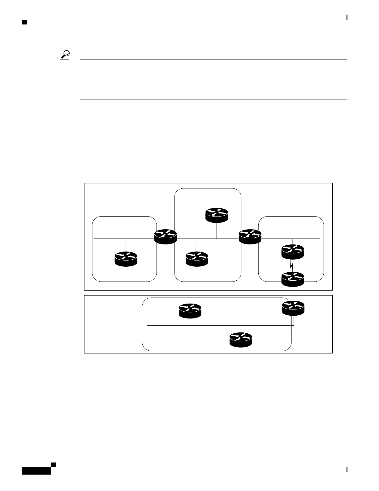
Figure 10 illustrates the routing components in an OSPF network topology.
Figure 10 OSPF Routing Components
Implementing OSPF on Cisco IOS XR Software
OSPF Domain
(BGP autonomous
system 109)
Area 2
stub area
OSPF Domain
(BGP autonomous
system 65200)
ABR 2
Area 0
backbone
R3
R2
Area 3
ABR 1
Area 1
R1
ASBR 1
ASBR 2
88721
Autonomous Systems
The autonomous system is a collection of networks, under the same administrative control, that share
routing information with each other. An autonomous system is also referred to as a routing domain.
Figure 10 shows two autonomous systems: A and B. An autonomous system can consist of one or more
OSPF areas.
Cisco IOS XR Routing Configuration Guide
RC-174
Page 7

Implementing OSPF on Cisco IOS XR Software
Areas
Areas allow the subdivision of an autonomous system into smaller, more manageable networks or sets
of adjacent networks. As shown in Figure 10, autonomous system A consists of three areas: Area 0, Area
1, and Area 2.
OSPF hides the topology of an area from the rest of the autonomous system. The network topology for
an area is visible only to routers inside that area. When OSPF routing is within an area, it is called
intra-area routing. This routing limits the amount of link-state information flood into the network,
reducing routing traffic. It also reduces the size of the topology information in each router, conserving
processing and memory requirements in each router.
Also, the routers within an area cannot see the detailed network topology outside the area. Because of
this restricted view of topological information, you can control traffic flow between areas and reduce
routing traffic when the entire autonomous system is a single routing domain.
Backbone Area
A backbone area is responsible for distributing routing information between multiple areas of an
autonomous system. OSPF routing occurring outside of an area is called interarea routing.
The backbone itself has all properties of an area. It consists of ABRs, routers, and networks only on the
backbone. As shown in Figure 10, Area 0 is an OSPF backbone area. Any OSPF backbone area has a
reserved area ID of 0.0.0.0.
Information About Implementing OSPF on Cisco IOS XR Software
Stub Area
Not-so-Stubby Area
A stub area is an area that does not accept or detailed network information external to the area. A stub
area typically has only one router that interfaces the area to the rest of the autonomous system. The stub
ABR advertises a single default route to external destinations into the stub area. Routers within a stub
area use this route for destinations outside the area and the autonomous system. This relationship
conserves LSA database space that would otherwise be used to store external LSAs flooded into the area.
In Figure 10, Area 2 is a stub area that is reached only through ABR 2. Area 0 cannot be a stub area.
A Not-so-Stubby Area (NSSA) is similar to the stub area. NSSA does not flood Type 5 external LSAs
from the core into the area, but can import autonomous system external routes in a limited fashion within
the area.
NSSA allows importing of Type 7 autonomous system external routes within an NSSA area by
redistribution. These Type 7 LSAs are translated into Type 5 LSAs by NSSA ABRs, which are flooded
throughout the whole routing domain. Summarization and filtering are supported during the translation.
Use NSSA to simplify administration if you are a network administrator that must connect a central site
using OSPF to a remote site that is using a different routing protocol.
Before NSSA, the connection between the corporate site border router and remote router could not be
run as an OSPF stub area because routes for the remote site could not be redistributed into a stub area,
and two routing protocols needed to be maintained. A simple protocol like RIP was usually run and
handled the redistribution. With NSSA, you can extend OSPF to cover the remote connection by defining
the area between the corporate router and remote router as an NSSA. Area 0 cannot be an NSSA.
Cisco IOS XR Routing Configuration Guide
RC-175
Page 8

Information About Implementing OSPF on Cisco IOS XR Software
Routers
The OSPF network is composed of ABRs, ASBRs, and interior routers.
Area Border Routers
An area border routers (ABR) is a router with multiple interfaces that connect directly to networks in
two or more areas. An ABR runs a separate copy of the OSPF algorithm and maintains separate routing
data for each area that is attached to, including the backbone area. ABRs also send configuration
summaries for their attached areas to the backbone area, which then distributes this information to other
OSPF areas in the autonomous system. In Figure 10, there are two ABRs. ABR 1 interfaces Area 1 to
the backbone area. ABR 2 interfaces the backbone Area 0 to Area 2, a stub area.
Autonomous System Boundary Routers (ASBR)
An autonomous system boudary router (ASBR) provides connectivity from one autonomous system to
another system. ASBRs exchange their autonomous system routing information with boundary routers
in other autonomous systems. Every router inside an autonomous system knows how to reach the
boundary routers for its autonomous system.
ASBRs can import external routing information from other protocols like BGP and redistribute them as
AS-external (ASE) Type 5 LSAs to the OSPF network. If the Cisco IOS XR router is an ASBR, you can
configure it to advertise VIP addresses for content as autonomous system external routes. In this way,
ASBRs flood information about external networks to routers within the OSPF network.
ASBR routes can be advertised as a Type 1 or Type 2 ASE. The difference between Type 1 and Type 2
is how the cost is calculated. For a Type 2 ASE, only the external cost (metric) is considered when
multiple paths to the same destination are compared. For a Type 1 ASE, the combination of the external
cost and cost to reach the ASBR is used. Type 2 external cost is the default and is always more costly
than an OSPF route and used only if no OSPF route exists.
Implementing OSPF on Cisco IOS XR Software
Interior Routers
The interior routers (such as R1 in Figure 10) attached to one area (for example, all the interfaces reside
in the same area).
OSPF Process and Router ID
An OSPF process is a logical routing entity running OSPF in a physical router. This logical routing entity
should not be confused with the logical routing feature that allows a system administrator (known as the
Cisco IOS XR Owner) to partition the physical box into separate routers.
A physical router can run multiple OSPF processes, although the only reason to do so would be to
connect two or more OSPF domains. Each process has its own link-state database. The routes in the
routing table are calculated from the link-state database. One OSPF process does not share routes with
another OSPF process unless the routes are redistributed.
Each OSPF process is identified by a router ID. The router ID must be unique across the entire routing
domain. OSPFv2 obtains a router ID from the following sources, in order of decreasing preference:
OSPF attempts to obtain a router ID in the following ways (in order of preference):
• The 32-bit numeric value specified by the OSPF router-id command in router configuration mode.
(This value can be any 32-bit value. It is not restricted to the IPv4 addresses assigned to interfaces
on this router, and need not be a routable IPv4 address.)
RC-176
Cisco IOS XR Routing Configuration Guide
Page 9

Implementing OSPF on Cisco IOS XR Software
• The primary IPv4 address of the interface specified by the OSPF router-id command.
• The 32-bit numeric value specified by the router-id command in global configuration mode. (This
value must be an IPv4 address assigned to an interface on this router.)
• By using the highest IPv4 address on a loopback interface in the system if the router is booted with
saved loopback address configuration.
• The primary IPv4 address of an interface over which this OSPF process is running.
We recommend that the router ID be set by the router-id command in router configuration mode.
Separate OSPF processes could share the same router ID, in which case they cannot reside in the same
OSPF routing domain.
Supported OSPF Network Types
OSPF classifies different media into the following three types of networks by default:
• NBMA networks
• Point-to-point networks (POS)
• Broadcast networks (Gigabit Ethernet)
Information About Implementing OSPF on Cisco IOS XR Software
You can configure your Cisco IOS XR network as either a broadcast or an NBMA network. Using this
feature, you can configure broadcast networks as NBMA networks when, for example, you have routers
in your network that do not support multicast addressing.
Route Authentication Methods for OSPF Version 2
OSPF Version 2 supports two types of authentication: plain text authentication and MD5 authentication.
By default, no authentication is enabled (referred to as null authentication in RFC 2178).
Plain Text Authentication
Plain text authentication (also known as Type 1 authentication) uses a password that travels on the
physical medium and is easily visible to someone that does not have access permission and could use the
password to infiltrate a network. Therefore, plain text authentication does not provide security. It might
protect against a faulty implementation of OSPF or a misconfigured OSPF interface trying to send
erroneous OSPF packets.
MD5 Authentication
MD5 authentication provides a means of security. No password travels on the physical medium. Instead,
the router uses MD5 to produce a message digest of the OSPF packet plus the key, which is sent on the
physical medium. Using MD5 authentication prevents a router from accepting unauthorized or
deliberately malicious routing updates, which could compromise your network security by diverting
your traffic.
Note MD5 authentication supports multiple keys, requiring that a key number be associated with a key.
Cisco IOS XR Routing Configuration Guide
RC-177
Page 10

Information About Implementing OSPF on Cisco IOS XR Software
Authentication Strategies
Authentication can be specified for an entire process or area, or on an interface or a virtual link. An
interface or virtual link can be configured for only one type of authentication, not both. Authentication
configured for an interface or virtual link overrides authentication configured for the area or process.
If you intend for all interfaces in an area to use the same type of authentication, you can configure fewer
commands if you use the authentication command in the area configuration submode (and specify the
message-digest keyword if you want the entire area to use MD5 authentication). This strategy requires
fewer commands than specifying authentication for each interface.
Key Rollover
To support the changing of an MD5 key in an operational network without disrupting OSPF adjacencies
(and hence the topology), a key rollover mechanism is supported. As a network administrator configures
the new key into the multiple networking devices that communicate, some time exists when different
devices are using both a new key and an old key. If an interface is configured with a new key, the software
sends two copies of the same packet, each authenticated by the old key and new key. The software tracks
which devices start using the new key, and the software stops sending duplicate packets after it detects
that all of its neighbors are using the new key. The software then discards the old key. The network
administrator must then remove the old key from each the configuration file of each router.
Implementing OSPF on Cisco IOS XR Software
Neighbors and Adjacency for OSPF
Routers that share a segment (Layer 2 link between two interfaces) become neighbors on that segment.
OSPF uses the hello protocol as a neighbor discovery and keep alive mechanism. The hello protocol
involves receiving and periodically sending hello packets out each interface. The hello packets list all
known OSPF neighbors on the interface. Routers become neighbors when they see themselves listed in
the hello packet of the neighbor. After two routers are neighbors, they may proceed to exchange and
synchronize their databases, which creates an adjacency. On broadcast and NBMA networks all
neighboring routers have an adjacency.
Designated Router (DR) for OSPF
On point-to-point and point-to-multipoint networks, the Cisco IOS XR software floods routing updates
to immediate neighbors. No DR or backup DR (BDR) exists; all routing information is flooded to each
router.
On broadcast or NBMA segments only, OSPF minimizes the amount of information being exchanged on
a segment by choosing one router to be a DR and one router to be a BDR. Thus, the routers on the
segment have a central point of contact for information exchange. Instead of each router exchanging
routing updates with every other router on the segment, each router exchanges information with the DR
and BDR. The DR and BDR relay the information to the other routers. On broadcast network segments
the number of OSPF packets is further reduced by the DR and BDR sending such OSPF updates to a
multicast IP address that all OSPF routers on the network segment are listening on.
The software looks at the priority of the routers on the segment to determine which routers are the DR
and BDR. The router with the highest priority is elected the DR. If there is a tie, then the router with the
higher router ID takes precedence. After the DR is elected, the BDR is elected the same way. A router
with a router priority set to zero is ineligible to become the DR or BDR.
RC-178
Cisco IOS XR Routing Configuration Guide
Page 11

Implementing OSPF on Cisco IOS XR Software
Information About Implementing OSPF on Cisco IOS XR Software
Default Route for OSPF,
Type 5 (ASE) LSAs are generated and flooded to all areas except stub areas. For the routers in a stub
area to be able to route packets to destinations outside the stub area, a default route is injected by the
ABR attached to the stub area.
The cost of the default route is 1 (default) or is determined by the value specified in the default-cost
command.
Link-State Advertisement Types for OSPF Version 2
Each of the following LSA types has a different purpose:
• Router LSA (Type 1)—Describes the links that the router has within a single area, and the cost of
each link. These LSAs are flooded within an area only. The LSA indicates if the router can compute
paths based on quality of service (QoS), whether it is an ABR or ASBR, and if it is one end of a
virtual link. Type 1 LSAs are also used to advertise stub networks.
• Network LSA (Type 2)—Describes the link state and cost information for all routers attached a
multiaccess network segment. This LSA lists all the routers that have interfaces attached to the
network segment. It is the job of the designated router of a network segment to generate and track
the contents of this LSA.
• Summary LSA for ABRs (Type 3)—Advertises internal networks to routers in other areas (interarea
routes). Type 3 LSAs may represent a single network or a set of networks aggregated into one prefix.
Only ABRs generate summary LSAs.
• Summary LSA for ASBRs (Type 4)—Advertises and ASBR and the cost to reach it. Routers that are
trying to reach an external network use these advertisements to determine the best path to the next
hop. ABRs generate Type 4 LSAs.
• Autonomous system external LSA (Type 5)—Redistributes routes from another autonomous system,
usually from a different routing protocol into OSPF.
Link-State Advertisement Types for OSPFv3
Each of the following LSA types has a different purpose:
• Router LSA (Type 1)—Describes the link state and costs of a the router link to the area. These LSAs
are flooded within an area only. The LSA indicates whether the router is an ABR or ASBR and if it
is one end of a virtual link. Type 1 LSAs are also used to advertise stub networks. In OSPFv3, these
LSAs have no address information and are network protocol independent. In OSPFv3, router
interface information may be spread across multiple router LSAs. Receivers must concatenate all
router LSAs originated by a given router before running the SPF calculation.
• Network LSA (Type 2)—Describes the link state and cost information for all routers attached to a
multiaccess network segment. This LSA lists all OSPF routers that have interfaces attached to the
network segment. Only the elected designated router for the network segment can generate and track
the network LSA for the segment. In OSPFv3, network LSAs have no address information and are
network-protocol-independent.
Cisco IOS XR Routing Configuration Guide
RC-179
Page 12

Information About Implementing OSPF on Cisco IOS XR Software
• Interarea-prefix LSA for ABRs (Type 3)—Advertises internal networks to routers in other areas
(interarea routes). Type 3 LSAs may represent a single network or set of networks aggregated into
one prefix. Only ABRs generate Type 3 LSAs. In OSPFv3, addresses for these LSAs are expressed
as “prefix and prefix length” instead of “address and mask.” The default route is expressed as a
prefix with length 0.
• Interarea-router LSA for ASBRs (Type 4)—Advertises an ASBR and the cost to reach it. Routers
that are trying to reach an external network use these advertisements to determine the best path to
the next hop. ABRs generate Type 4 LSAs.
• Autonomous system external LSA (Type 5)—Redistributes routes from another autonomous system,
usually from a different routing protocol into OSPF. In OSPFv3, addresses for these LSAs are
expressed as “prefix and prefix length” instead of “address and mask.” The default route is expressed
as a prefix with length 0.
• Autonomous system external LSA (Type 7)—Provides for carrying external route information
within an NSSA. Type 7 LSAs may be originated by and advertised throughout an NSSA. NSSAs
do not receive or originate Type 5 LSAs. Type 7 LSAs are advertised only within a single NSSA.
They are not flooded into the the backbone area or any otehr area by border routers.
• Link LSA (Type 8)—Has link-local flooding scope and is never flooded beyond the link with which
it is associated. Link LSAs provide the link-local address of the router to all other routers attached
to the link or network segment, inform other routers attached to the link of a list of IPv6 prefixes to
associate with the link, and allow the router to assert a collection of Options bits to associate with
the network LSA that is originated for the link.
Implementing OSPF on Cisco IOS XR Software
• Intra-area-prefix LSAs (Type 9)—A router can originate multiple intra-area-prefix LSAs for every
router or transit network, each with a unique link-state ID. The link-state ID for each
intra-area-prefix LSA describes its association to either the router LSA or network LSA and contains
prefixes for stub and transit networks.
An address prefix occurs in almost all newly defined LSAs. The prefix is represented by three fields:
Prefix Length, Prefix Options, and Address Prefix. In OSPFv3, addresses for these LSAs are expressed
as “prefix and prefix length” instead of “address and mask.” The default route is expressed as a prefix
with length 0.
Inter-area-prefix and intra-area-prefix LSAs carry all IPv6 prefix information that, in IPv4, is included
in router LSAs and network LSAs. The Options field in certain LSAs (router LSAs, network LSAs,
interarea-router LSAs, and link LSAs) has been expanded to 24 bits to provide support for OSPF in IPv6.
In OSPFv3, the sole function of link-state ID in interarea-prefix LSAs, interarea-router LSAs, and
autonomous system external LSAs is to identify individual pieces of the link-state database. All
addresses or router IDs that are expressed by the link-state ID in OSPF Version 2 are carried in the body
of the LSA in OSPFv3.
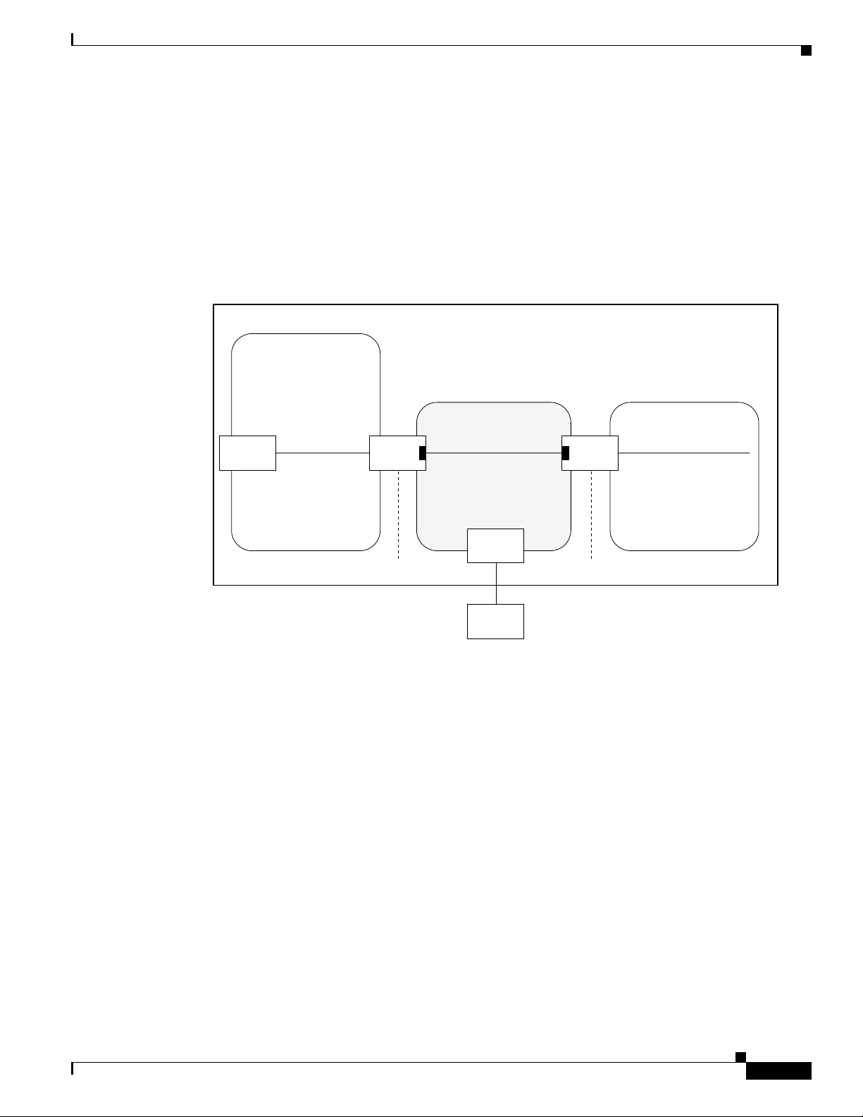
Virtual Link and Transit Area for OSPF
In OSPF, routing information from all areas is first summarized to the backbone area by ABRs. The same
ABRs, in turn, propagate such received information to their attached areas. Such hierarchical
distribution of routing information requires that all areas be connected to the backbone area (Area 0).
Occasions might exist for which an area must be defined, but it cannot be physically connected to Area 0.
Examples of such an occasion might be if your company makes a new acquisition that includes an OSPF
area, or if Area 0 itself is partitioned.
RC-180
Cisco IOS XR Routing Configuration Guide
Page 13
Implementing OSPF on Cisco IOS XR Software
In the case in which an area cannot be connected to Area 0, you must configure a virtual link between
that area and Area 0. The two endpoints of a virtual link are ABRs, and the virtual link must be
configured in both routers. The common nonbackbone area to which the two routers belong is called a
transit area. A virtual link specifies the transit area and the router ID of the other virtual endpoint (the
other ABR).
A virtual link cannot be configured through a stub area or NSSA.
Figure 11 illustrates a virtual link from Area 3 to Area 0.
Figure 11 Virtual Link to Area 0
OSPF Domain (BGP autonomous system 109)
Backbone
Information About Implementing OSPF on Cisco IOS XR Software
Area 0
Route Redistribution for OSPF
Redistribution allows different routing protocols to exchange routing information. This technique can be
used to allow connectivity to span multiple routing protocols. It is important to remember that the
redistribute command controls redistribution into an OSPF process and not from OSPF. See the
“Configuration Examples for Implementing OSPF on Cisco IOS XR Software” section on page 236 for
an example of route redistribution for OSPF.
Area 1
ABR 1ABR 2
Transit Area
ASBR 1
Router ID 5.5.5.5 Router ID 4.4.4.4
ASBR 2
ABR 3
Area 3
88722
OSPF Shortest Path First Throttling
OSPF SPF throttling makes it possible to configure SPF scheduling in millisecond intervals and to
potentially delay SPF calculations during network instability. SPF is scheduled to calculate the Shortest
Path Tree (SPT) when there is a change in topology. One SPF run may include multiple topology change
events.
Cisco IOS XR Routing Configuration Guide
RC-181
Page 14

Information About Implementing OSPF on Cisco IOS XR Software
The interval at which the SPF calculations occur is chosen dynamically and based on the frequency of
topology changes in the network. The chosen interval is within the boundary of the user-specified value
ranges. If network topology is unstable, SPF throttling calculates SPF scheduling intervals to be longer
until topology becomes stable.
SPF calculations occur at the interval set by the timers throttle spf command. The wait interval
indicates the amount of time to wait until the next SPF calculation occurs. Each wait interval after that
calculation is twice as long as the previous interval until the interval reaches the maximum wait time
specified.
The SPF timing can be better explained using an example. In this example, the start interval is set at
5 milliseconds (ms), initial wait interval at 1000 ms, and maximum wait time at 90,000 ms.
timers spf 5 1000 90000
Figure 12 shows the intervals at which the SPF calculations occur as long as at least one topology change
event is received in a given wait interval.
Figure 12 SPF Calculation Intervals Set by the timers spf Command
Implementing OSPF on Cisco IOS XR Software
5 ms
2000 ms
1000 ms
4000 ms
8000 ms
16000 ms
32000 ms
90000 ms
64000 ms
Notice that the wait interval between SPF calculations doubles when at least one topology change event
is received during the previous wait interval. After the maximum wait time is reached, the wait interval
remains the same until the topology stabilizes and no event is received in that interval.
If the first topology change event is received after the current wait interval, the SPF calculation is
delayed by the amount of time specified as the start interval. The subsequent wait intervals continue to
follow the dynamic pattern.
If the first topology change event occurs after the maximum wait interval begins, the SPF calculation is
again scheduled at the start interval and subsequent wait intervals are reset according to the parameters
specified in the timers throttle spf command. Notice in Figure 13 that a topology change event was
received after the start of the maximum wait time interval and that the SPF intervals have been reset.
Figure 13 Timer Intervals Reset After Topology Change Event
Topology change event
64000 ms
90000 ms
1000 ms
5 ms
SPF scheduled at
start interval
2000 ms
4000 ms
8000 ms
16000 ms
90000 ms
88279
88278
Nonstop Forwarding for OSPF Version 2
Cisco IOS XR NSF for OSPF Version 2 allows for the forwarding of data packets to continue along
known routes while the routing protocol information is being restored following a failover. With NSF,
peer networking devices do not experience routing flaps. During failover, data traffic is forwarded
Cisco IOS XR Routing Configuration Guide
RC-182
Page 15

Implementing OSPF on Cisco IOS XR Software
through intelligent line cards while the standby Route Processor (RP) assumes control from the failed
RP. The ability of line cards to remain up through a failover and to be kept current with the Forwarding
Information Base (FIB) on the active RP is key to Cisco IOS XR NSF operation.
Routing protocols, such as OSPF, run only on the active RP or DRP and receive routing updates from
their neighbor routers. When an OSPF NSF-capable router performs an RP failover, it must perform two
tasks to resynchronize its link-state database with its OSPF neighbors. First, it must relearn the available
OSPF neighbors on the network without causing a reset of the neighbor relationship. Second, it must
reacquire the contents of the link-state database for the network.
As quickly as possible after an RP failover, the NSF-capable router sends an OSPF NSF signal to
neighboring NSF-aware devices. This signal is in the form of a link-local LSA generated by the
failed-over router. Neighbor networking devices recognize this signal as a cue that the neighbor
relationship with this router should not be reset. As the NSF-capable router receives signals from other
routers on the network, it can begin to rebuild its neighbor list.
After neighbor relationships are re-established, the NSF-capable router begins to resynchronize its
database with all of its NSF-aware neighbors. At this point, the routing information is exchanged
between the OSPF neighbors. After this exchange is completed, the NSF-capable device uses the routing
information to remove stale routes, update the RIB, and update the FIB with the new forwarding
information. OSPF on the router as well as the OSPF neighbors are now fully converged.
How to Implement OSPF on Cisco IOS XR Software
Note The standardized IETF version of NSF, known as OSPF graceful restart (RFC 3623) is also supported.
Load Balancing in OSPF Version 2 and OSPFv3
When a router learns multiple routes to a specific network by using multiple routing processes (or
routing protocols), it installs the route with the lowest administrative distance in the routing table.
Sometimes the router must select a route from among many learned by using the same routing process
with the same administrative distance. In this case, the router chooses the path with the lowest cost (or
metric) to the destination. Each routing process calculates its cost differently; the costs may need to be
manipulated to achieve load balancing.
OSPF performs load balancing automatically. If OSPF finds that it can reach a destination through more
than one interface and each path has the same cost, it installs each path in the routing table. The only
restriction on the number of paths to the same destination is controlled by the maximum-paths (OSPF)
command. The default number of maximum paths is 32 for Cisco CRS-1 routers and 16 for
Cisco XR 12000 Series Routers. The range is from 1 to 32 for Cisco CRS-1 routers and 1 to 16 for
Cisco XR 12000 Series Routers.
How to Implement OSPF on Cisco IOS XR Software
This section contains the following procedures:
• Enabling OSPF, page RC-184 (required)
• Configuring Stub and Not-so-Stubby Area Types, page RC-186 (optional)
• Configuring Neighbors for Nonbroadcast Networks, page RC-189 (optional)
• Configuring Authentication at Different Hierarchical Levels for OSPF Version 2, page RC-194
(optional)
Cisco IOS XR Routing Configuration Guide
RC-183
Page 16

How to Implement OSPF on Cisco IOS XR Software
• Controlling the Frequency that the Same LSA Is Originated or Accepted for OSPF, page RC-197
(optional)
• Creating a Virtual Link with MD5 Authentication to Area 0 for OSPF, page RC-199 (optional)
• Summarizing Subnetwork LSAs on an OSPF ABR, page RC-203 (optional)
• Redistributing Routes from One IGP into OSPF, page RC-205 (optional)
• Configuring OSPF Shortest Path First Throttling, page RC-209 (optional)
• Configuring Nonstop Forwarding for OSPF Version 2, page RC-212 (optional)
• Configuring OSPF Version 2 for MPLS Traffic Engineering, page RC-214 (optional)
• Verifying OSPF Configuration and Operation, page RC-219 (optional)
• Configuring OSPFv3 Graceful Restart, page RC-221 (optional)
• Enabling Multicast-Intact for OSPFv2, page RC-225 (optional)
• Configuring the Multi-VRF Capability for OSPF Routing, page RC-227 (optional)
• Associating Interfaces to a VRF, page RC-228 (optional)
• Configuring OSPF as a Provider Edge to Customer Edge (PE-CE) Protocol, page RC-230 (optional)
• Configuring LDP-IGP Synchronization, page RC-233 (optional)
Implementing OSPF on Cisco IOS XR Software
Enabling OSPF
Prerequisites
SUMMARY STEPS
• Creating Multiple OSPF Instances (OSPF Process and a VRF), page RC-235 (optional)
This task explains how to perform the minimum OSPF configuration on your router that is to enable an
OSPF process with a router ID, configure a backbone or nonbackbone area, and then assign one or more
interfaces on which OSPF runs.
Although you can configure OSPF before you configure an IP address, no OSPF routing occurs until at
least one IP address is configured.
1. configure
2. router ospf process-name
or
router ospfv3 process-name
3. router-id {ipv4-address | interface-type interface-instance}
4. area area-id
5. interface type instance
RC-184
6. Repeat Step 5 for each interface that use OSPF.
7. log adjacency changes [detail] [enable | disable]
8. end
or
commit
Cisco IOS XR Routing Configuration Guide
Page 17

Implementing OSPF on Cisco IOS XR Software
DETAILED STEPS
Command or Action Purpose
Step 1
configure
Example:
RP/0/RP0/CPU0:router# configure
Step 2
router ospf process-name
or
router ospfv3 process-name
Example:
RP/0/RP0/CPU0:router(config)# router ospf 1
or
RP/0/RP0/CPU0:router(config)# router ospfv3 1
Step 3
router-id {ipv4-address | interface-type
interface-instance}
Example:
RP/0/RP0/CPU0:router(config-ospf)# router-id
192.168.4.3
Step 4
area area-id
How to Implement OSPF on Cisco IOS XR Software
Enters global configuration mode.
Enables OSPF routing for the specified routing process and
places the router in router configuration mode.
or
Enables OSPFv3 routing for the specified routing process
and places the router in router ospfv3 configuration mode.
Note The process-name argument is any alphanumeric
string no longer than 40 characters.
Configures a router ID for the OSPF process.
Note We recommend using a stable IP address as the
router ID.
Enters area configuration mode and configures an area for
the OSPF process.
Step 5
Step 6
Example:
RP/0/RP0/CPU0:router(config-ospf)# area 0
interface type instance
Enters interface configuration mode and associates one or
more interfaces for the area configured in Step 4.
Example:
RP/0/RP0/CPU0:router(config-ospf-ar)# interface
POS 0/1/0/3
Repeat Step 5 for each interface that uses OSPF. —
• Backbone areas have an area ID of 0.
• Nonbackbone areas have a nonzero area ID.
• The area-id argument can be entered in dotted-decimal
or IPv4 address notation, such as area 1000 or
area 0.0.3.232. However, you must choose one form or
the other for an area. We recommend using the IPv4
address notation.
Cisco IOS XR Routing Configuration Guide
RC-185
Page 18

How to Implement OSPF on Cisco IOS XR Software
Command or Action Purpose
Step 7
log adjacency changes [detail] [enable |
disable]
Example:
RP/0/RP0/CPU0:router(config-ospf-ar-if)# log
adjacency changes detail
Step 8
end
or
commit
Example:
RP/0/RP0/CPU0:router(config-ospf-ar-if)# end
or
RP/0/RP0/CPU0:router(config-ospf-ar-if)# commit
Implementing OSPF on Cisco IOS XR Software
(Optional) Requests notification of neighbor changes.
• By default, this feature is enabled.
• The messages generated by neighbor changes are
considered notifications, which are categorized as
severity Level 5 in the logging console command. The
logging console command controls which severity
level of messages are sent to the console. By default, all
severity level messages are sent.
Saves configuration changes.
• When you issue the end command, the system prompts
you to commit changes:
Uncommitted changes found, commit them before
exiting(yes/no/cancel)?
[cancel]:
–
Entering yes saves configuration changes to the
running configuration file, exits the configuration
session, and returns the router to EXEC mode.
–
Entering no exits the configuration session and
returns the router to EXEC mode without
committing the configuration changes.
–
Entering cancel leaves the router in the current
configuration session without exiting or
committing the configuration changes.
• Use the commit command to save the configuration
changes to the running configuration file and remain
within the configuration session.
Configuring Stub and Not-so-Stubby Area Types
This task explains how to configure the stub area and the NSSA for OSPF.
SUMMARY STEPS
1. configure
2. router ospf process-name
or
router ospfv3 process-name
3. router-id {ipv4-address | interface-type interface-instance}
4. area area-id
5. stub [no-summary]
or
nssa [no-redistribution] [default-information-originate] [no-summary]
RC-186
Cisco IOS XR Routing Configuration Guide
Page 19

Implementing OSPF on Cisco IOS XR Software
6. stub
or
nssa
7. default-cost cost
8. end
or
commit
9. Repeat this task on all other routers in the stub area or NSSA.
DETAILED STEPS
Command or Action Purpose
Step 1
configure
Example:
RP/0/RP0/CPU0:router# configure
Step 2
router ospf process-name
or
router ospfv3 process-name
Example:
RP/0/RP0/CPU0:router(config)# router ospf 1
or
RP/0/RP0/CPU0:router(config)# router ospfv3 1
Step 3
router-id {ipv4-address | interface-type
interface-instance}
Example:
RP/0/RP0/CPU0:router(config-ospf)# router-id
192.168.4.3
Step 4
area area-id
Example:
RP/0/RP0/CPU0:router(config-ospf)# area 1
How to Implement OSPF on Cisco IOS XR Software
Enters global configuration mode.
Enables OSPF routing for the specified routing process and
places the router in router configuration mode.
or
Enables OSPFv3 routing for the specified routing process
and places the router in router ospfv3 configuration mode.
Note The process-name argument is any alphanumeric
string no longer than 40 characters.
Configures a router ID for the OSPF process.
Note We recommend using a stable IP address as the
router ID.
Enters area configuration mode and configures a
nonbackbone area for the OSPF process.
• The area-id argument can be entered in dotted-decimal
or IPv4 address notation, such as area 1000 or
area 0.0.3.232. However, you must choose one form or
the other for an area. We recommend using the IPv4
address notation.
Cisco IOS XR Routing Configuration Guide
RC-187
Page 20

How to Implement OSPF on Cisco IOS XR Software
Command or Action Purpose
Step 5
stub [no-summary]
or
nssa [no-redistribution]
[default-information-originate] [no-summary]
Example:
RP/0/RP0/CPU0:router(config-ospf-ar)# stub no
summary
or
RP/0/RP0/CPU0:router(config-ospf-ar)# nssa
no-redistribution
Step 6
stub
or
nssa
Example:
RP/0/RP0/CPU0:router(config-ospf-ar)# stub
or
RP/0/RP0/CPU0:router(config-ospf-ar)# nssa
Step 7
default-cost cost
Example:
RP/0/RP0/CPU0:router(config-ospf-ar)#
default-cost 15
Implementing OSPF on Cisco IOS XR Software
Defines the nonbackbone area as a stub area.
• See the “Configuring Stub and Not-so-Stubby Area
Types” section on page 186.
• Specify the no-summary keyword to further reduce the
number of LSAs sent into a stub area. This keyword
prevents the ABR from sending summary link-state
advertisements (Type 3) in the stub area.
or
Defines an area as an NSSA.
• See the “Configuring Stub and Not-so-Stubby Area
Types” section on page 186.
(Optional) Turns off the options configured for stub and
NSSA areas.
• If you configured the stub and NSSA areas using the
optional keywords (no-summary, no-redistribution,
default-information-originate, and no-summary) in
Step 5, you must now reissue the stub and nssa
commands without the keywords—rather than using
the no form of the command.
• For example, the no nssa
default-information-originate form of the command
changes the NSSA area into a normal area that
inadvertently brings down the existing adjacencies in
that area.
(Optional) Specifies a cost for the default summary route
sent into a stub area or an NSSA.
• Use this command only on ABRs attached to the NSSA.
Do not use it on any other routers in the area.
• The default cost is 1.
RC-188
Cisco IOS XR Routing Configuration Guide
Page 21

Implementing OSPF on Cisco IOS XR Software
Command or Action Purpose
Step 8
end
or
commit
Example:
RP/0/RP0/CPU0:router(config-ospf-ar)# end
or
RP/0/RP0/CPU0:router(config-ospf-ar)# commit
Step 9
Repeat this task on all other routers in the stub area or
NSSA.
How to Implement OSPF on Cisco IOS XR Software
Saves configuration changes.
• When you issue the end command, the system prompts
you to commit changes:
Uncommitted changes found, commit them before
exiting(yes/no/cancel)?
[cancel]:
–
Entering yes saves configuration changes to the
running configuration file, exits the configuration
session, and returns the router to EXEC mode.
–
Entering no exits the configuration session and
returns the router to EXEC mode without
committing the configuration changes.
–
Entering cancel leaves the router in the current
configuration session without exiting or
committing the configuration changes.
• Use the commit command to save the configuration
changes to the running configuration file and remain
within the configuration session.
—
Configuring Neighbors for Nonbroadcast Networks
This task explains how to configure neighbors for a nonbroadcast network. This task is optional.
Prerequisites
Configuring NBMA networks as either broadcast or nonbroadcast assumes that there are virtual circuits
from every router to every router or fully meshed network.
SUMMARY STEPS
1. configure
2. router ospf process-name
or
router ospfv3 process-name
3. router-id {ipv4-address | interface-type interface-instance}
4. area area-id
5. network {broadcast | non-broadcast | {point-to-multipoint [non-broadcast] | point-to-point}}
6. dead-interval seconds
7. hello-interval seconds
8. interface type number
Cisco IOS XR Routing Configuration Guide
RC-189
Page 22

How to Implement OSPF on Cisco IOS XR Software
9. neighbor ip-address [priority number] [poll-interval seconds] [cost number]
or
neighbor ipv6-link-local-address [priority number] [poll-interval seconds] [cost number]
[database-filter [all]]
10. Repeat Step 9 for all neighbors on the interface.
11. exit
12. interface type instance
13. neighbor ip-address [priority number] [poll-interval seconds][cost number] [database-filter
[all]]
or
neighbor ipv6-link-local-address [priority number] [poll-interval seconds][cost number]
[database-filter [all]]
14. Repeat Step 13 for all neighbors on the interface.
15. end
or
commit
Implementing OSPF on Cisco IOS XR Software
DETAILED STEPS
Command or Action Purpose
Step 1
configure
Example:
RP/0/RP0/CPU0:router# configure
Step 2
router ospf process-name
or
router ospfv3 process-name
Example:
RP/0/RP0/CPU0:router(config)# router ospf 1
or
RP/0/RP0/CPU0:router(config)# router ospfv3 1
Step 3
router-id {ipv4-address | interface-type
interface-instance}
Example:
RP/0/RP0/CPU0:router(config-ospf)# router-id
192.168.4.3
Step 4
area area-id
Example:
RP/0/RP0/CPU0:router(config-ospf)# area 0
Enters global configuration mode.
Enables OSPF routing for the specified routing process and
places the router in router configuration mode.
or
Enables OSPFv3 routing for the specified routing process
and places the router in router ospfv3 configuration mode.
Note The process-name argument is any alphanumeric
string no longer than 40 characters.
Configures a router ID for the OSPF process.
Note We recommend using a stable IP address as the
router ID.
Enters area configuration mode and configures an area for
the OSPF process.
• The example configures a backbone area.
• The area-id argument can be entered in dotted-decimal
or IPv4 address notation, such as area 1000 or
area 0.0.3.232. However, you must choose one form or
the other for an area. We recommend using the IPv4
address notation.
RC-190
Cisco IOS XR Routing Configuration Guide
Page 23

Implementing OSPF on Cisco IOS XR Software
Command or Action Purpose
Step 5
network {broadcast | non-broadcast |
{point-to-multipoint [non-broadcast] |
point-to-point}}
Example:
RP/0/RP0/CPU0:router(config-ospf-ar)# network
non-broadcast
Step 6
dead-interval seconds
Example:
RP/0/RP0/CPU0:router(config-ospf-ar)#
dead-interval 40
Step 7
hello-interval seconds
Example:
RP/0/RP0/CPU0:router(config-ospf-ar)#
hello-interval 10
Step 8
interface type instance
Example:
RP/0/RP0/CPU0:router(config-ospf-ar)# interface
POS 0/2/0/0
How to Implement OSPF on Cisco IOS XR Software
Configures the OSPF network type to a type other than the
default for a given medium.
• The example sets the network type to NBMA.
(Optional) Sets the time to wait for a hello packet from a
neighbor before declaring the neighbor down.
(Optional) Specifies the interval between hello packets that
OSPF sends on the interface.
Enters interface configuration mode and associates one or
more interfaces for the area configured in Step 4.
• In this example, the interface inherits the nonbroadcast
network type and the hello and dead intervals from the
areas because the values are not set at the interface
level.
Cisco IOS XR Routing Configuration Guide
RC-191
Page 24

How to Implement OSPF on Cisco IOS XR Software
Command or Action Purpose
Step 9
neighbor ip-address [priority number]
[poll-interval seconds][cost number]
or
neighbor ipv6-link-local-address [priority
number]
[database-filter [all]]
[poll-interval seconds][cost number]
Example:
RP/0/RP0/CPU0:router(config-ospf-ar-if)#
neighbor 10.20.20.1 priority 3 poll-interval 15
or
RP/0/RP0/CPU0:router(config-ospf-ar-if)#
neighbor fe80::3203:a0ff:fe9d:f3fe
Implementing OSPF on Cisco IOS XR Software
Configures the IPv4 address of OSPF neighbors
interconnecting to nonbroadcast networks.
or
Configures the link-local IPv6 address of OSPFv3
neighbors.
• The ipv6-link-local-address argument must be in the
form documented in RFC 2373 in which the address is
specified in hexadecimal using 16-bit values between
colons.
• The priority keyword notifies the router that this
neighbor is eligible to become a DR or BDR. The
priority value should match the actual priority setting
on the neighbor router. The neighbor priority default
value is zero. This keyword does not apply to
point-to-multipoint interfaces.
• The poll-interval keyword does not apply to
point-to-multipoint interfaces. RFC 1247 recommends
that this value be much larger than the hello interval.
The default is 120 seconds (2 minutes).
Step 10
Step 11
Step 12
Repeat Step 9 for all neighbors on the interface. —
exit
Enters area configuration mode.
Example:
RP/0/RP0/CPU0:router(config-ospf-ar-if)# exit
interface type instance
Enters interface configuration mode and associates one or
more interfaces for the area configured in Step 4.
Example:
RP/0/RP0/CPU0:router(config-ospf-ar)# interface
POS 0/3/0/1
• Neighbors with no specific cost configured assumes the
cost of the interface, based on the cost command. On
point-to-multipoint interfaces, cost number is the only
keyword and argument combination that works. The
cost keyword does not apply to NBMA networks.
• The database-filter keyword filters outgoing LSAs to
an OSPF neighbor. If you specify the all keyword,
incoming and outgoing LSAs are filtered. Use with
extreme caution since filtering may cause the routing
topology to be seen as entirely different between two
neighbors, resulting in ‘black-holing’ of data traffic or
routing loops.
• In this example, the interface inherits the nonbroadcast
network type and the hello and dead intervals from the
areas because the values are not set at the interface
level.
RC-192
Cisco IOS XR Routing Configuration Guide
Page 25

Implementing OSPF on Cisco IOS XR Software
Command or Action Purpose
Step 13
neighbor ip-address [priority number]
[poll-interval seconds][cost number]
[database-filter [all]]
or
neighbor ipv6-link-local-address [priority
number] [poll-interval seconds][cost number]
[database-filter [all]]
Example:
RP/0/RP0/CPU0:router(config-ospf-ar)# neighbor
10.34.16.6
or
RP/0/RP0/CPU0:router(config-ospf-ar)# neighbor
fe80::3203:a0ff:fe9d:f3f
How to Implement OSPF on Cisco IOS XR Software
Configures the IPv4 address of OSPF neighbors
interconnecting to nonbroadcast networks.
or
Configures the link-local IPv6 address of OSPFv3
neighbors.
• The ipv6-link-local-address argument must be in the
form documented in RFC 2373 in which the address is
specified in hexadecimal using 16-bit values between
colons.
• The priority keyword notifies the router that this
neighbor is eligible to become a DR or BDR. The
priority value should match the actual priority setting
on the neighbor router. The neighbor priority default
value is zero. This keyword does not apply to
point-to-multipoint interfaces.
• The poll-interval keyword does not apply to
point-to-multipoint interfaces. RFC 1247 recommends
that this value be much larger than the hello interval.
The default is 120 seconds (2 minutes).
• Neighbors with no specific cost configured assumes the
cost of the interface, based on the cost command. On
point-to-multipoint interfaces, cost number is the only
keyword and argument combination that works. The
cost keyword does not apply to NBMA networks.
• The database-filter keyword filters outgoing LSAs to
an OSPF neighbor. If you specify the all keyword,
incoming and outgoing LSAs are filtered. Use with
extreme caution since filtering may cause the routing
topology to be seen as entirely different between two
neighbors, resulting in ‘black-holing’ or routing loops.
Cisco IOS XR Routing Configuration Guide
RC-193
Page 26

How to Implement OSPF on Cisco IOS XR Software
Command or Action Purpose
Step 14
Step 15
Repeat Step 13 for all neighbors on the interface. —
end
or
commit
Example:
RP/0/RP0/CPU0:router(config-ospf-ar)# end
or
RP/0/RP0/CPU0:router(config-ospf-ar)# commit
Implementing OSPF on Cisco IOS XR Software
Saves configuration changes.
• When you issue the end command, the system prompts
you to commit changes:
Uncommitted changes found, commit them before
exiting(yes/no/cancel)?
[cancel]:
–
Entering yes saves configuration changes to the
running configuration file, exits the configuration
session, and returns the router to EXEC mode.
–
Entering no exits the configuration session and
returns the router to EXEC mode without
committing the configuration changes.
–
Entering cancel leaves the router in the current
configuration session without exiting or
committing the configuration changes.
• Use the commit command to save the configuration
changes to the running configuration file and remain
within the configuration session.
Configuring Authentication at Different Hierarchical Levels for OSPF Version 2
This task explains how to configure MD5 (secure) authentication on the OSPF router process, configure
one area with plain text authentication, and then apply one interface with clear text (null) authentication.
Note Authentication configured at the interface level overrides authentication configured at the area level and
the router process level. If an interface does not have authentication specifically configured, the interface
inherits the authentication parameter value from a higher hierarchical level. See the “OSPF Hierarchical
CLI and CLI Inheritance” section on page 173 for more information about hierarchy and inheritance.
Prerequisites
If you choose to configure authentication, you must first decide whether to configure plain text or MD5
authentication, and whether the authentication applies to all interfaces in a process, an entire area, or
specific interfaces. See the “Route Authentication Methods for OSPF Version 2” section on page 177 for
information about each type of authentication and when you should use a specific method for your
network.
SUMMARY STEPS
1. configure
2. router ospf process-name
3. router-id {ipv4-address | interface-type interface-instance}
RC-194
4. authentication [message-digest | null]
Cisco IOS XR Routing Configuration Guide
Page 27

Implementing OSPF on Cisco IOS XR Software
5. message-digest-key key-id md5 {key | clear key | encrypted key}
6. area area-id
7. interface type instance
8. Repeat Step 7 for each interface that must communicate, using the same authentication.
9. exit
10. area area-id
11. authentication [message-digest | null]
12. interface type instance
13. Repeat Step 7 for each interface that must communicate, using the same authentication.
14. interface type instance
15. authentication [message-digest | null]
16. end
or
commit
How to Implement OSPF on Cisco IOS XR Software
DETAILED STEPS
Command or Action Purpose
Step 1
configure
Example:
RP/0/RP0/CPU0:router# configure
Step 2
router ospf process-name
Example:
RP/0/RP0/CPU0:router(config)# router ospf 1
Step 3
router-id {ipv4-address | interface-type
interface-instance}
Example:
RP/0/RP0/CPU0:router(config-ospf)# router-id
192.168.4.3
Step 4
authentication [message-digest | null]
Example:
RP/0/RP0/CPU0:router(config-ospf)#
authentication message-digest
Step 5
message-digest-key key-id md5 {key | clear key
| encrypted key}
Enters global configuration mode.
Enables OSPF routing for the specified routing process and
places the router in router configuration mode.
Note The process-name argument is any alphanumeric
string no longer than 40 characters.
Configures a router ID for the OSPF process.
Enables MD5 authentication for the OSPF process.
• This authentication type applies to the entire router
process unless overridden by a lower hierarchical level
such as the area or interface.
Specifies the MD5 authentication key for the OSPF process.
• The neighbor routers must have the same key identifier.
Example:
RP/0/RP0/CPU0:router(config-ospf)#
message-digest-key 4 md5 yourkey
Cisco IOS XR Routing Configuration Guide
RC-195
Page 28

How to Implement OSPF on Cisco IOS XR Software
Command or Action Purpose
Step 6
area area-id
Example:
RP/0/RP0/CPU0:router(config-ospf)# area 0
Step 7
interface type instance
Example:
RP/0/RP0/CPU0:router(config-ospf-ar)# interface
POS 0/1/0/3
Step 8
Repeat Step 7 for each interface that must
communicate, using the same authentication.
Step 9
exit
Example:
RP/0/RP0/CPU0:router(config-ospf-ar)# exit
Step 10
area area-id
Example:
RP/0/RP0/CPU0:router(config-ospf)# area 1
Step 11
authentication [message-digest | null]
Example:
RP/0/RP0/CPU0:router(config-ospf-ar)#
authentication
Step 12
interface type instance
Example:
RP/0/RP0/CPU0:router(config-ospf-ar)# interface
POS 0/1/0/0
Step 13
Repeat Step 12 for each interface that must
communicate, using the same authentication.
Step 14
interface type instance
Implementing OSPF on Cisco IOS XR Software
Enters area configuration mode and configures a backbone
area for the OSPF process.
Enters interface configuration mode and associates one or
more interfaces to the backbone area.
• All interfaces inherit the authentication parameter
values specified for the OSPF process (Step 4, Step 5,
and Step 6).
—
Enters area OSPF configuration mode.
Enters area configuration mode and configures a
nonbackbone area 1 for the OSPF process.
• The area-id argument can be entered in dotted-decimal
or IPv4 address notation, such as area 1000 or
area 0.0.3.232. However, you must choose one form or
the other for an area. We recommend using the IPv4
address notation.
Enables Type 1 (plain text) authentication that provides no
security.
• The example specifies plain text authentication (by not
specifying a keyword). Use the authentication-key
interface command to specify the plain text password.
Enters interface configuration mode and associates one or
more interfaces to the nonbackbone area 1 specified in
Step 7.
• All interfaces configured inherit the authentication
parameter values configured for area 1.
—
Enters interface configuration mode and associates one or
more interfaces to a different authentication type.
RC-196
Example:
RP/0/RP0/CPU0:router(config-ospf-ar)# interface
POS 0/3/0/0
Cisco IOS XR Routing Configuration Guide
Page 29

Implementing OSPF on Cisco IOS XR Software
Command or Action Purpose
Step 15
Step 16
authentication [message-digest | null]
Example:
RP/0/RP0/CPU0:router(config-ospf-ar-if)#
authentication null
end
or
commit
Example:
RP/0/RP0/CPU0:router(config-ospf-ar-if)# end
or
RP/0/RP0/CPU0:router(config-ospf-ar-if)# commit
How to Implement OSPF on Cisco IOS XR Software
Specifies no authentication on POS interface 0/3/0/0,
overriding the plain text authentication specified for area 1.
• By default, all of the interfaces configured in the same
area inherit the same authentication parameter values of
the area.
Saves configuration changes.
• When you issue the end command, the system prompts
you to commit changes:
Uncommitted changes found, commit them before
exiting(yes/no/cancel)?
[cancel]:
–
Entering yes saves configuration changes to the
running configuration file, exits the configuration
session, and returns the router to EXEC mode.
–
Entering no exits the configuration session and
returns the router to EXEC mode without
committing the configuration changes.
–
Entering cancel leaves the router in the current
configuration session without exiting or
committing the configuration changes.
• Use the commit command to save the configuration
changes to the running configuration file and remain
within the configuration session.
Controlling the Frequency that the Same LSA Is Originated or Accepted for OSPF
This task explains how to tune the convergence time of OSPF routes in the routing table when many
LSAs need to be flooded in a very short time interval.
SUMMARY STEPS
1. configure
2. router ospf process-name
or
router ospfv3 process-name
3. router-id {ipv4-address | interface-type interface-instance}
4. Perform Step 5 or Step 6 or both to control the frequency that the same LSA is originated or
accepted.
5. timers lsa gen-interval seconds
6. timers lsa min-arrival seconds
7. timers lsa group-pacing seconds
Cisco IOS XR Routing Configuration Guide
RC-197
Page 30

How to Implement OSPF on Cisco IOS XR Software
8. end
or
commit
DETAILED STEPS
Command or Action Purpose
Step 1
configure
Example:
RP/0/RP0/CPU0:router# configure
Step 2
router ospf process-name
or
router ospfv3 process-name
Example:
RP/0/RP0/CPU0:router(config)# router ospf 1
or
RP/0/RP0/CPU0:router(config)# router ospfv3 1
Step 3
router-id {ipv4-address | interface-type
interface-instance}
Example:
RP/0/RP0/CPU0:router(config-ospf)# router-id
192.168.4.3
Step 4
Perform Step 5 or Step 6 or both to control the
frequency that the same LSA is originated or accepted.
Step 5
timers lsa gen-interval seconds
Example:
RP/0/RP0/CPU0:router(config-ospf)# timers lsa
gen-interval 10
Step 6
timers lsa min-arrival seconds
Example:
RP/0/RP0/CPU0:router(config-ospf)# timers lsa
min-arrival 2
Implementing OSPF on Cisco IOS XR Software
Enters global configuration mode.
Enables OSPF routing for the specified routing process and
places the router in router configuration mode.
or
Enables OSPFv3 routing for the specified routing process
and places the router in router ospfv3 configuration mode.
Note The process-name argument is any alphanumeric
string no longer than 40 characters.
Configures a router ID for the OSPF process.
Note We recommend using a stable IP address as the
router ID.
—
Changes the minimum interval between the same OSPF
LSAs that the router originates.
• The default is 5 seconds for both OSPF and OSPFv3.
Limits the frequency that new processes of any particular
OSPF Version 2 LSA can be accepted during flooding.
• The default is 1 second.
RC-198
Cisco IOS XR Routing Configuration Guide
Page 31

Implementing OSPF on Cisco IOS XR Software
Command or Action Purpose
Step 7
Step 8
timers lsa group-pacing seconds
Example:
RP/0/RP0/CPU0:router(config-ospf)# timers lsa
group-pacing 1000
end
or
commit
Example:
RP/0/RP0/CPU0:router(config-ospf)# end
or
RP/0/RP0/CPU0:router(config-ospf)# commit
How to Implement OSPF on Cisco IOS XR Software
Changes the interval at which OSPF link-state LSAs are
collected into a group for flooding.
• The default is 240 seconds.
Saves configuration changes.
• When you issue the end command, the system prompts
you to commit changes:
Uncommitted changes found, commit them before
exiting(yes/no/cancel)?
[cancel]:
–
Entering yes saves configuration changes to the
running configuration file, exits the configuration
session, and returns the router to EXEC mode.
–
Entering no exits the configuration session and
returns the router to EXEC mode without
committing the configuration changes.
–
Entering cancel leaves the router in the current
configuration session without exiting or
committing the configuration changes.
• Use the commit command to save the configuration
changes to the running configuration file and remain
within the configuration session.
Creating a Virtual Link with MD5 Authentication to Area 0 for OSPF
This task explains how to create a virtual link to your backbone (area 0) and apply MD5 authentication.
You must perform the steps described on both ABRs, one at each end of the virtual link. To understand
virtual links, see the “Virtual Link and Transit Area for OSPF” section on page 180.
Note After you explicitly configure area parameter values, they are inherited by all interfaces bound to that
area—unless you override the values and configure them explicitly for the interface. An example is
provided in the “Virtual Link Configured with MD5 Authentication for OSPF Version 2: Example”
section on page 241.
Prerequisites
The following prerequisites must be met before creating a virtual link with MD5 authentication to area 0:
• You must have the router ID of the neighbor router at the opposite end of the link to configure the
local router. You can execute the show ospf or show ospfv3 command on the remote router to get
its router ID.
Cisco IOS XR Routing Configuration Guide
RC-199
Page 32

How to Implement OSPF on Cisco IOS XR Software
• For a virtual link to be successful, you need a stable router ID at each end of the virtual link. You
do not want them to be subject to change, which could happen if they are assigned by default (See
the “OSPF Process and Router ID” section on page 176 for an explanation of how the router ID is
determined.) Therefore, we recommend that you perform one of the following tasks before
configuring a virtual link:
–
Use the router-id command to set the router ID. This strategy is preferable.
–
Configure a loopback interface so that the router has a stable router ID.
• Before configuring your virtual link for OSPF Version 2, you must decide whether to configure plain
text authentication, MD5 authentication, or no authentication (which is the default). Your decision
determines whether you need to perform additional tasks related to authentication.
Note If you decide to configure plain text authentication or no authentication, see the authentication
command provided in the OSPF Commands on Cisco IOS XR Software module in the Cisco IOS XR
Routing Command Reference.
SUMMARY STEPS
Implementing OSPF on Cisco IOS XR Software
1. show ospf [process-name]
or
show ospfv3 [process-name]
2. configure
3. router ospf process-name
or
router ospfv3 process-name
4. router-id {ipv4-address | interface-type interface-instance}
5. area area-id
6. virtual link rout er-id
7. authentication message-digest
8. message-digest-key key-id md5 {key | clear key | encrypted key}
9. Repeat all of the steps in this task on the ABR that is at the other end of the virtual link. Specify the
same key ID and key that you specified for the virtual link on this router.
10. end
or
commit
11. show ospf [process-name] [area-id] virtual-links
or
show ospfv3 [process-name] virtual-links
RC-200
Cisco IOS XR Routing Configuration Guide
Page 33

Implementing OSPF on Cisco IOS XR Software
DETAILED STEPS
Command or Action Purpose
Step 1
show ospf [process-name]
or
show ospfv3 [process-name]
Example:
RP/0/RP0/CPU0:router# show ospf
or
RP/0/RP0/CPU0:router# show ospfv3
Step 2
configure
Example:
RP/0/RP0/CPU0:router# configure
Step 3
router ospf process-name
or
router ospfv3 process-name
Example:
RP/0/RP0/CPU0:router(config)# router ospf 1
or
RP/0/RP0/CPU0:router(config)# router ospfv3 1
Step 4
router-id {ipv4-address | interface-type
interface-instance}
Example:
RP/0/RP0/CPU0:router(config-ospf)# router-id
192.168.4.3
Step 5
area area-id
Example:
RP/0/RP0/CPU0:router(config-ospf)# area 1
Step 6
virtual-link router-id
How to Implement OSPF on Cisco IOS XR Software
(Optional) Displays general information about OSPF
routing processes.
• The output displays the router ID of the local router.
You need this router ID to configure the other end of the
link.
Enters global configuration mode.
Enables OSPF routing for the specified routing process and
places the router in router configuration mode.
or
Enables OSPFv3 routing for the specified routing process
and places the router in router ospfv3 configuration mode.
Note The process-name argument is any alphanumeric
string no longer than 40 characters.
Configures a router ID for the OSPF process.
Note We recommend using a stable IPv4 address as the
router ID.
Enters area configuration mode and configures a
nonbackbone area for the OSPF process.
• The area-id argument can be entered in dotted-decimal
or IPv4 address notation, such as area 1000 or
area 0.0.3.232. However, you must choose one form or
the other for an area. We recommend using the IPv4
address notation.
Defines an OSPF virtual link.
Step 7
Example:
RP/0/RP0/CPU0:router(config-ospf-ar)# virtual
link 10.3.4.5
authentication message-digest
Example:
RP/0/RP0/CPU0:router(config-ospf-ar-vl)#
authentication message-digest
• See the “Virtual Link and Transit Area for OSPF”
section on page 180.
Selects MD5 authentication for this virtual link.
Cisco IOS XR Routing Configuration Guide
RC-201
Page 34

How to Implement OSPF on Cisco IOS XR Software
Command or Action Purpose
Step 8
message-digest-key key-id md5 {key | clear key
| encrypted key}
Example:
RP/0/RP0/CPU0:router(config-ospf-ar-vl)#
message-digest-key 4 md5 yourkey
Step 9
Repeat all of the steps in this task on the ABR that is
at the other end of the virtual link. Specify the same
key ID and key that you specified for the virtual link
on this router.
Step 10
end
or
commit
Example:
RP/0/RP0/CPU0:router(config-ospf-ar-vl)# end
or
RP/0/RP0/CPU0:router(config-ospf-ar-vl)# commit
Implementing OSPF on Cisco IOS XR Software
Defines an OSPF virtual link.
• See the “Virtual Link and Transit Area for OSPF”
section on page 180 to understand a virtual link.
• The key-id argument is a number in the range from 1 to
255. The key argument is an alphanumeric string of up
to 16 characters. The routers at both ends of the virtual
link must have the same key identifier and key to be
able to route OSPF traffic.
• The authentication-key key command is not supported
for OSPFv3.
• Once the key is encrypted it must remain encrypted.
—
Saves configuration changes.
• When you issue the end command, the system prompts
you to commit changes:
Uncommitted changes found, commit them before
exiting(yes/no/cancel)?
[cancel]:
–
Entering yes saves configuration changes to the
running configuration file, exits the configuration
session, and returns the router to EXEC mode.
Step 11
show ospf [process-name] [area-id]
virtual-links
or
show ospfv3 [process-name] virtual-links
Example:
RP/0/RP0/CPU0:router# show ospf 1 2
virtual-links
or
RP/0/RP0/CPU0:router# show ospfv3 1
virtual-links
–
Entering no exits the configuration session and
returns the router to EXEC mode without
committing the configuration changes.
–
Entering cancel leaves the router in the current
configuration session without exiting or
committing the configuration changes.
• Use the commit command to save the configuration
changes to the running configuration file and remain
within the configuration session.
(Optional) Displays the parameters and the current state of
OSPF virtual links.
RC-202
Cisco IOS XR Routing Configuration Guide
Page 35

Implementing OSPF on Cisco IOS XR Software
Examples
In the following example, the show ospfv3 virtual links EXEC command verifies that the OSPF_VL0
virtual link to the OSPFv3 neighbor is up, the ID of the virtual link interface is 2, and the IPv6 address
of the virtual link endpoint is 2003:3000::1.
RP/0/RP0/CPU0:router# show ospfv3 virtual-links
Virtual Links for OSPFv3 1
Virtual Link OSPF_VL0 to router 10.0.0.3 is up
Interface ID 2, IPv6 address 2003:3000::1
Run as demand circuit
DoNotAge LSA allowed.
Transit area 0.1.20.255, via interface POS 0/1/0/1, Cost of using 2
Transmit Delay is 5 sec, State POINT_TO_POINT,
Timer intervals configured, Hello 10, Dead 40, Wait 40, Retransmit 5
Hello due in 00:00:02
Adjacency State FULL (Hello suppressed)
Index 0/2/3, retransmission queue length 0, number of retransmission 1
First 0(0)/0(0)/0(0) Next 0(0)/0(0)/0(0)
Last retransmission scan length is 1, maximum is 1
Last retransmission scan time is 0 msec, maximum is 0 msec
How to Implement OSPF on Cisco IOS XR Software
Check for lines:
Virtual Link OSPF_VL0 to router 10.0.0.3 is up
Adjacency State FULL (Hello suppressed)
State is up and Adjacency State is FULL
Summarizing Subnetwork LSAs on an OSPF ABR
If you configured two or more subnetworks when you assigned your IP addresses to your interfaces, you
might want the software to summarize (aggregate) into a single LSA all of the subnetworks that the local
area advertises to another area. Such summarization would reduce the number of LSAs and thereby
conserve network resources. This summarization is known as interarea route summarization. It applies
to routes from within the autonomous system. It does not apply to external routes injected into OSPF by
way of redistribution.
This task configures OSPF to summarize subnetworks into one LSA, by specifying that all subnetworks
that fall into a range are advertised together. This task is performed on an ABR only.
SUMMARY STEPS
1. configure
2. router ospf process-name
or
router ospfv3 process-name
3. router-id {ipv4-address | interface-type interface-instance}
4. area area-id
5. range ip-address mask [advertise | not-advertise]
or
range ipv6-prefix/prefix-length [advertise | not-advertise]
6. interface type instance
Cisco IOS XR Routing Configuration Guide
RC-203
Page 36

How to Implement OSPF on Cisco IOS XR Software
7. end
or
commit
DETAILED STEPS
Command or Action Purpose
Step 1
configure
Example:
RP/0/RP0/CPU0:router# configure
Step 2
router ospf process-name
or
router ospfv3 process-name
Example:
RP/0/RP0/CPU0:router(config)# router ospf 1
or
RP/0/RP0/CPU0:router(config)# router ospfv3 1
Step 3
router-id {ipv4-address | interface-type
interface-instance}
Example:
RP/0/RP0/CPU0:router(config-ospf)# router-id
192.168.4.3
Step 4
area area-id
Example:
RP/0/RP0/CPU0:router(config-ospf)# area 0
Step 5
range ip-address mask [advertise |
not-advertise]
or
range ipv6-prefix/prefix-length [advertise |
not-advertise]
Example:
RP/0/RP0/CPU0:router(config-ospf-ar)# range
192.168.0.0 255.255.0.0 advertise
or
Example:
RP/0/RP0/CPU0:router(config-ospf-ar)# range
4004:f000::/32 advertise
Implementing OSPF on Cisco IOS XR Software
Enters global configuration mode.
Enables OSPF routing for the specified routing process and
places the router in router configuration mode.
or
Enables OSPFv3 routing for the specified routing process
and places the router in router ospfv3 configuration mode.
Note The process-name argument is any alphanumeric
string no longer than 40 characters.
Configures a router ID for the OSPF process.
Note We recommend using a stable IPv4 address as the
router ID.
Enters area configuration mode and configures a
nonbackbone area for the OSPF process.
• The area-id argument can be entered in dotted-decimal
or IPv4 address notation, such as area 1000 or
area 0.0.3.232. However, you must choose one form or
the other for an area. We recommend using the IPv4
address notation.
Consolidates and summarizes OSPF routes at an area
boundary.
• The advertise keyword causes the software to advertise
the address range of subnetworks in a Type 3 summary
LSA.
• The not-advertise keyword causes the software to
suppress the Type 3 summary LSA, and the
subnetworks in the range remain hidden from other
areas.
• In the first example, all subnetworks for network
192.168.0.0 are summarized and advertised by the ABR
into areas outside the backbone.
• In the second example, two or more IPv4 interfaces are
covered by a 192.x.x network.
RC-204
Cisco IOS XR Routing Configuration Guide
Page 37

Implementing OSPF on Cisco IOS XR Software
Command or Action Purpose
Step 6
Step 7
interface type instance
Example:
RP/0/RP0/CPU0:router(config-ospf-ar)# interface
POS 0/2/0/3
end
or
commit
Example:
RP/0/RP0/CPU0:router(config-ospf-ar)# end
or
RP/0/RP0/CPU0:router(config-ospf-ar)# commit
How to Implement OSPF on Cisco IOS XR Software
Enters interface configuration mode and associates one or
more interfaces to the area.
Saves configuration changes.
• When you issue the end command, the system prompts
you to commit changes:
Uncommitted changes found, commit them before
exiting(yes/no/cancel)?
[cancel]:
–
Entering yes saves configuration changes to the
running configuration file, exits the configuration
session, and returns the router to EXEC mode.
–
Entering no exits the configuration session and
returns the router to EXEC mode without
committing the configuration changes.
–
• Use the commit command to save the configuration
changes to the running configuration file and remain
within the configuration session.
Redistributing Routes from One IGP into OSPF
This task redistributes routes from an IGP (could be a different OSPF process) into OSPF.
Prerequisites
For information about configuring routing policy, see the Implementing Routing Policy on Cisco IOS XR
Software module.
SUMMARY STEPS
1. configure
2. router ospf process-name
or
router ospfv3 process-name
3. router-id {ipv4-address | interface-type interface-instance}
Entering cancel leaves the router in the current
configuration session without exiting or
committing the configuration changes.
4. redistribute protocol [process-id] {level-1 | level-1-2 | level-2} [metric metric-value] [metric-type
type-value] [match {internal | external [1 | 2} | nssa-external [1 | 2}] [tag tag-value] [route-map
map-tag | route-policy policy-tag]
Cisco IOS XR Routing Configuration Guide
RC-205
Page 38

How to Implement OSPF on Cisco IOS XR Software
5. summary-prefix address mask [not-advertise] [tag tag]
or
summary-prefix ipv6-prefix/prefix-length [not-advertise] [tag tag]
6. end
or
commit
DETAILED STEPS
Command or Action Purpose
Step 1
configure
Example:
RP/0/RP0/CPU0:router# configure
Step 2
router ospf process-name
or
router ospfv3 process-name
Implementing OSPF on Cisco IOS XR Software
Enters global configuration mode.
Enables OSPF routing for the specified routing process and
places the router in router configuration mode.
or
Step 3
Example:
RP/0/RP0/CPU0:router(config)# router ospf 1
or
RP/0/RP0/CPU0:router(config)# router ospfv3 1
router-id {ipv4-address | interface-type
interface-instance}
Example:
RP/0/RP0/CPU0:router(config-ospf)# router-id
192.168.4.3
Enables OSPFv3 routing for the specified routing process
and places the router in router ospfv3 configuration mode.
Note The process-name argument is any alphanumeric
string no longer than 40 characters.
Configures a router ID for the OSPF process.
Note We recommend using a stable IPv4 address as the
router ID.
RC-206
Cisco IOS XR Routing Configuration Guide
Page 39

Implementing OSPF on Cisco IOS XR Software
Command or Action Purpose
Step 4
redistribute protocol [process-id] {level-1 |
level-1-2 | level-2} [metric metric-value]
[metric-type type-value] [match {internal |
external [1 | 2} | nssa-external [1 | 2}] [tag
tag-value] [route-map map-tag | policy
policy-tag]
How to Implement OSPF on Cisco IOS XR Software
Redistributes OSPF routes from one routing domain to
another routing domain.
or
Redistributes OSPFv3 routes from one routing domain to
another routing domain.
Example:
RP/0/RP0/CPU0:router(config-ospf)# redistribute
bgp 1 level-1
or
RP/0/RP0/CPU0:router(config-router)#
redistribute bgp 1 level-1-2 metric-type 1
• This command causes the router to become an ASBR
by definition.
• OSPF tags all routes learned through redistribution as
external.
• The protocol and its process ID, if it has one, indicate
the protocol being redistributed into OSPF.
• The metric is the cost you assign to the external route.
The default is 20 for all protocols except BGP, whose
default metric is 1.
• The OSPF example redistributes BGP autonomous
system 1, Level 1 routes into OSPF as Type 2 external
routes.
• The OSPFv3 example redistributes BGP autonomous
system 1, Level 1 and 2 routes into OSPF. The external
link type associated with the default route advertised
into the OSPFv3 routing domain is the Type 1 external
route.
Note RPL is not supported for OSPFv3.
Cisco IOS XR Routing Configuration Guide
RC-207
Page 40

How to Implement OSPF on Cisco IOS XR Software
Command or Action Purpose
Step 5
summary-prefix address mask [not-advertise]
[tag tag]
or
summary-prefix ipv6-prefix/prefix-length
[not-advertise] [tag tag]
Example:
RP/0/RP0/CPU0:router(config-ospf)#
summary-prefix 10.1.0.0 255.255.0.0
or
RP/0/RP0/CPU0:router(config-router)#
summary-prefix 2010:11:22::/32
Step 6
end
or
commit
Example:
RP/0/RP0/CPU0:router(config-ospf)# end
or
RP/0/RP0/CPU0:router(config-ospf)# commit
Implementing OSPF on Cisco IOS XR Software
(Optional) Creates aggregate addresses for OSPF.
or
(Optional) Creates aggregate addresses for OSPFv3.
• This command provides external route summarization
of the non-OSPF routes.
• External ranges that are being summarized should be
contiguous. Summarization of overlapping ranges from
two different routers could cause packets to be sent to
the wrong destination.
• This command is optional. If you do not specify it, each
route is included in the link-state database and
advertised in LSAs.
• In the OSPFv2 example, the summary address 10.1.0.0
includes address 10.1.1.0, 10.1.2.0, 10.1.3.0, and so on.
Only the address 10.1.0.0 is advertised in an external
LSA.
• In the OSPFv3 example, the summary address
2010:11:22::/32 has addresses such as
2010:11:22:0:1000::1, 2010:11:22:0:2000:679:1, and
so on. Only the address 2010:11:22::/32 is advertised in
the external LSA.
Saves configuration changes.
• When you issue the end command, the system prompts
you to commit changes:
Uncommitted changes found, commit them before
exiting(yes/no/cancel)?
[cancel]:
–
Entering yes saves configuration changes to the
running configuration file, exits the configuration
session, and returns the router to EXEC mode.
–
Entering no exits the configuration session and
returns the router to EXEC mode without
committing the configuration changes.
–
Entering cancel leaves the router in the current
configuration session without exiting or
committing the configuration changes.
RC-208
• Use the commit command to save the configuration
changes to the running configuration file and remain
within the configuration session.
Cisco IOS XR Routing Configuration Guide
Page 41

Implementing OSPF on Cisco IOS XR Software
Configuring OSPF Shortest Path First Throttling
This task explains how to configure SPF scheduling in millisecond intervals and potentially delay SPF
calculations during times of network instability. This task is optional.
Prerequisites
See the “OSPF Shortest Path First Throttling” section on page 181 for information about OSPF SPF
throttling.
SUMMARY STEPS
1. configure
2. router ospf process-name
or
router ospfv3 process-name
3. router-id {ipv4-address | interface-type interface-instance}
4. timers throttle spf spf-start spf-hold spf-max-wait
How to Implement OSPF on Cisco IOS XR Software
DETAILED STEPS
Command or Action Purpose
Step 1
Step 2
configure
Example:
RP/0/RP0/CPU0:router# configure
router ospf process-name
or
router ospfv3 process-name
Example:
RP/0/RP0/CPU0:router(config)# router ospf 1
or
RP/0/RP0/CPU0:router(config)# router ospfv3 1
5. area area-id
6. interface type instance
7. end
or
commit
8. show ospf [process-name]
or
show ospfv3 [process-name]
Enters global configuration mode.
Enables OSPF routing for the specified routing process and
places the router in router configuration mode.
or
Enables OSPFv3 routing for the specified routing process
and places the router in router ospfv3 configuration mode.
Note The process-name argument is any alphanumeric
string no longer than 40 characters.
Cisco IOS XR Routing Configuration Guide
RC-209
Page 42

How to Implement OSPF on Cisco IOS XR Software
Command or Action Purpose
Step 3
router-id {ipv4-address | interface-type
interface-instance}
Example:
RP/0/RP0/CPU0:router(config-ospf)# router-id
192.168.4.3
Step 4
timers throttle spf spf-start spf-hold
spf-max-wait
Example:
RP/0/RP0/CPU0:router(config-ospf)# timers
throttle spf 10 4800 90000
Step 5
area area-id
Example:
RP/0/RP0/CPU0:router(config-ospf)# area 0
Step 6
interface type instance
Implementing OSPF on Cisco IOS XR Software
Configures a router ID for the OSPF process.
Note We recommend using a stable IPv4 address as the
router ID.
Sets SPF throttling timers.
Enters area configuration mode and configures a backbone
area.
• The area-id argument can be entered in dotted-decimal
or IPv4 address notation, such as area 1000 or
area 0.0.3.232. However, you must choose one form or
the other for an area. We recommend using the IPv4
address notation.
Enters interface configuration mode and associates one or
more interfaces to the area.
Example:
RP/0/RP0/CPU0:router(config-ospf-ar)# interface
POS 0/1/0/3
RC-210
Cisco IOS XR Routing Configuration Guide
Page 43

Implementing OSPF on Cisco IOS XR Software
Command or Action Purpose
Step 7
end
or
commit
Example:
RP/0/RP0/CPU0:router(config-ospf-ar-if)# end
or
RP/0/RP0/CPU0:router(config-ospf-ar-if)# commit
Step 8
show ospf [process-name]
or
show ospfv3 [process-name]
How to Implement OSPF on Cisco IOS XR Software
Saves configuration changes.
• When you issue the end command, the system prompts
you to commit changes:
Uncommitted changes found, commit them before
exiting(yes/no/cancel)?
[cancel]:
–
Entering yes saves configuration changes to the
running configuration file, exits the configuration
session, and returns the router to EXEC mode.
–
Entering no exits the configuration session and
returns the router to EXEC mode without
committing the configuration changes.
–
Entering cancel leaves the router in the current
configuration session without exiting or
committing the configuration changes.
• Use the commit command to save the configuration
changes to the running configuration file and remain
within the configuration session.
(Optional) Displays SPF throttling timers.
Example:
RP/0/RP0/CPU0:router# show ospf 1
or
RP/0/RP0/CPU0:router# show ospfv3 2
Examples
In the following example, the show ospf EXEC command is used to verify that the initial SPF schedule
delay time, minimum hold time, and maximum wait time are configured correctly. Additional details are
displayed about the OSPF process, such as the router type and redistribution of routes.
RP/0/RP0/CPU0:router# show ospf 1
Routing Process "ospf 1" with ID 192.168.4.3
Supports only single TOS(TOS0) routes
Supports opaque LSA
It is an autonomous system boundary router
Redistributing External Routes from,
ospf 2
Initial SPF schedule delay 5 msecs
Minimum hold time between two consecutive SPFs 100 msecs
Maximum wait time between two consecutive SPFs 1000 msecs
Minimum LSA interval 5 secs. Minimum LSA arrival 1 secs
Number of external LSA 0. Checksum Sum 00000000
Number of opaque AS LSA 0. Checksum Sum 00000000
Number of DCbitless external and opaque AS LSA 0
Number of DoNotAge external and opaque AS LSA 0
Number of areas in this router is 1. 1 normal 0 stub 0 nssa
External flood list length 0
Cisco IOS XR Routing Configuration Guide
RC-211
Page 44

How to Implement OSPF on Cisco IOS XR Software
Non-Stop Forwarding enabled
Note For a description of each output display field, see the show ospf command in the OSPF Commands on
Cisco IOS XR Software module in the Cisco IOS XR Routing Command Reference document.
Configuring Nonstop Forwarding for OSPF Version 2
This task explains how to configure OSPF NSF on your NSF-capable router. This task is optional.
Prerequisites
OSPF NSF requires that all neighbor networking devices be NSF aware, which happens automatically
after you install the Cisco IOS XR image on the router. If an NSF-capable router discovers that it has
non-NSF-aware neighbors on a particular network segment, it disables NSF capabilities for that
segment. Other network segments composed entirely of NSF-capable or NSF-aware routers continue to
provide NSF capabilities.
See the “Nonstop Forwarding for OSPF Version 2” section on page 182 for conceptual information.
Implementing OSPF on Cisco IOS XR Software
Restrictions
SUMMARY STEPS
The following are restrictions when configuring nonstop forwarding:
• OSPF Cisco NSF for virtual links is not supported.
• Neighbors must be NSF aware.
1. configure
2. router ospf process-name
3. router-id {ipv4-address | interface-type interface-instance}
4. nsf
or
nsf enforce global
5. nsf interval seconds
6. end
or
commit
RC-212
Cisco IOS XR Routing Configuration Guide
Page 45

Implementing OSPF on Cisco IOS XR Software
DETAILED STEPS
Command or Action Purpose
Step 1
configure
Example:
RP/0/RP0/CPU0:router# configure
Step 2
router ospf process-name
How to Implement OSPF on Cisco IOS XR Software
Enters global configuration mode.
Enables OSPF routing for the specified routing process and
places the router in router configuration mode.
Step 3
Step 4
Example:
RP/0/RP0/CPU0:router(config)# router ospf 1
router-id {ipv4-address | interface-type
interface-instance}
Example:
RP/0/RP0/CPU0:router(config-ospf)# router-id
192.168.4.3
nsf
or
nsf enforce global
Example:
RP/0/RP0/CPU0:router(config-ospf)# nsf
or
RP/0/RP0/CPU0:router(config-ospf)# nsf enforce
global
Note The process-name argument is any alphanumeric
string no longer than 40 characters.
Configures a router ID for the OSPF process.
Note We recommend using a stable IPv4 address as the
router ID.
Enables OSPF NSF operations.
• Use the nsf command without the optional enforce and
global keywords to abort the NSF restart mechanism on
the interfaces of detected non-NSF neighbors and allow
NSF neighbors to function properly.
• Use the nsf command with the optional enforce and
global keywords if the router is expected to perform
NSF during restart. However, if non-NSF neighbors are
detected, NSF restart is canceled for the entire OSPF
process.
Cisco IOS XR Routing Configuration Guide
RC-213
Page 46

How to Implement OSPF on Cisco IOS XR Software
Command or Action Purpose
Step 5
Step 6
nsf interval seconds
Example:
RP/0/RP0/CPU0:router(config-ospf)# nsf interval
120
end
or
commit
Example:
RP/0/RP0/CPU0:router(config-ospf)# end
or
RP/0/RP0/CPU0:router(config-ospf)# commit
Implementing OSPF on Cisco IOS XR Software
Sets the minimum time between NSF restart attempts.
Note When you use this command, the OSPF process
must be up for at least 90 seconds before OSPF
attempts to perform an NSF restart.
Saves configuration changes.
• When you issue the end command, the system prompts
you to commit changes:
Uncommitted changes found, commit them before
exiting(yes/no/cancel)?
[cancel]:
–
Entering yes saves configuration changes to the
running configuration file, exits the configuration
session, and returns the router to EXEC mode.
–
Entering no exits the configuration session and
returns the router to EXEC mode without
committing the configuration changes.
–
Entering cancel leaves the router in the current
configuration session without exiting or
committing the configuration changes.
• Use the commit command to save the configuration
changes to the running configuration file and remain
within the configuration session.
Configuring OSPF Version 2 for MPLS Traffic Engineering
This task explains how to configure OSPF for MPLS TE. This task is optional.
For a description of the MPLS TE tasks and commands that allow you to configure the router to support
tunnels, configure an MPLS tunnel that OSPF can use, and troubleshoot MPLS TE, see the Implementing
MPLS Traffic Engineering Configuration Guide.
Prerequisites
Your network must support the following Cisco IOS XR features before you enable MPLS TE for OSPF
on your router:
• MPLS
• IP Cisco Express Forwarding (CEF)
RC-214
Note You must enter the commands in the following task on every OSPF router in the traffic-engineered
portion of your network.
Cisco IOS XR Routing Configuration Guide
Page 47

Implementing OSPF on Cisco IOS XR Software
Restrictions
MPLS traffic engineering currently supports only a single OSPF area.
SUMMARY STEPS
1. configure
2. router ospf process-name
3. router-id {ipv4-address | interface-type interface-instance}
4. mpls traffic-eng area area-id
5. mpls traffic-eng router-id {ip-address | interface-type interface-instance}
6. area area-id
7. interface type instance
8. end
or
commit
How to Implement OSPF on Cisco IOS XR Software
DETAILED STEPS
Command or Action Purpose
Step 1
configure
Example:
RP/0/RP0/CPU0:router# configure
Step 2
router ospf process-name
Example:
RP/0/RP0/CPU0:router(config)# router ospf 1
Step 3
router-id {ipv4-address | interface-type
interface-instance}
Example:
RP/0/RP0/CPU0:router(config-ospf)# router-id
192.168.4.3
Step 4
mpls traffic-eng area area-id
9. show ospf [process-name] [area-id] mpls traffic-eng {link | fragment}
Enters global configuration mode.
Enables OSPF routing for the specified routing process and
places the router in router configuration mode.
Note The process-name argument is any alphanumeric
string no longer than 40 characters.
Configures a router ID for the OSPF process.
Note We recommend using a stable IPv4 address as the
router ID.
Configures the OSPF area for MPLS TE.
Example:
RP/0/RP0/CPU0:router(config-ospf)# mpls
traffic-eng area 0
Cisco IOS XR Routing Configuration Guide
RC-215
Page 48

How to Implement OSPF on Cisco IOS XR Software
Command or Action Purpose
Step 5
mpls traffic-eng router-id {ip-address |
interface-type interface-instance}
Example:
RP/0/RP0/CPU0:router(config-ospf)# mpls
traffic-eng router-id loopback 0
Step 6
area area-id
Example:
RP/0/RP0/CPU0:router(config-ospf)# area 0
Step 7
interface type instance
Implementing OSPF on Cisco IOS XR Software
(Optional) Specifies that the traffic engineering router
identifier for the node is the IP address associated with a
given interface.
• This IP address is flooded to all nodes in TE LSAs.
• For all traffic engineering tunnels originating at other
nodes and ending at this node, you must set the tunnel
destination to the traffic engineering router identifier of
the destination node because that is the address that the
traffic engineering topology database at the tunnel head
uses for its path calculation.
• We recommend that loopback interfaces be used for
MPLS TE router ID because they are more stable than
physical interfaces.
Enters area configuration mode and configures an area for
the OSPF process.
• The area-id argument can be entered in dotted-decimal
or IPv4 address notation, such as area 1000 or
area 0.0.3.232. However, you must choose one form or
the other for an area.
Enters interface configuration mode and associates one or
more interfaces to the area.
Example:
RP/0/RP0/CPU0:router(config-ospf-ar)# interface
interface loopback0
RC-216
Cisco IOS XR Routing Configuration Guide
Page 49

Implementing OSPF on Cisco IOS XR Software
Command or Action Purpose
Step 8
end
or
commit
Example:
RP/0/RP0/CPU0:router(config-ospf-ar-if)# end
or
RP/0/RP0/CPU0:router(config-ospf-ar-if)# commit
Step 9
show ospf [process-name] [area-id] mpls
traffic-eng {link | fragment}
How to Implement OSPF on Cisco IOS XR Software
Saves configuration changes.
• When you issue the end command, the system prompts
you to commit changes:
Uncommitted changes found, commit them before
exiting(yes/no/cancel)?
[cancel]:
–
Entering yes saves configuration changes to the
running configuration file, exits the configuration
session, and returns the router to EXEC mode.
–
Entering no exits the configuration session and
returns the router to EXEC mode without
committing the configuration changes.
–
Entering cancel leaves the router in the current
configuration session without exiting or
committing the configuration changes.
• Use the commit command to save the configuration
changes to the running configuration file and remain
within the configuration session.
(Optional) Displays information about the links and
fragments available on the local router for MPLS TE.
Example:
RP/0/RP0/CPU0:router# show ospf 1 0 mpls
traffic-eng link
Examples
This section provides the following output examples:
• Sample Output for the show ospf Command Before Configuring MPLS TE, page RC-217
• Sample Output for the show ospf mpls traffic-eng Command, page RC-218
• Sample Output for the show ospf Command After Configuring MPLS TE, page RC-219
Sample Output for the show ospf Command Before Configuring MPLS TE
In the following example, the show route ospf EXEC command verifies that POS interface 0/3/0/0 exists
and MPLS TE is not configured:
RP/0/RP0/CPU0:router# show route ospf 1 0
O E2 192.168.10.0/24 [110/20] via 192.168.1.2, 00:02:50, POS 0/3/0/0
[110/20] via 192.168.4.1, 00:02:50, POS 0/3/0/1
O E2 192.168.11.0/24 [110/20] via 192.168.1.2, 00:02:50, POS 0/3/0/0
[110/20] via 192.168.4.1, 00:02:50, POS 0/3/0/1
O E2 192.168.244.0/24 [110/20] via 192.168.1.2, 00:02:50, POS 0/3/0/0
[110/20] via 192.168.4.1, 00:02:50, POS 0/3/0/1
O 192.168.12.0/24 [110/2] via 192.168.1.2, 00:02:50, POS 0/3/0/0
[110/2] via 192.168.4.1, 00:02:50, POS 0/3/0/1
Cisco IOS XR Routing Configuration Guide
RC-217
Page 50

How to Implement OSPF on Cisco IOS XR Software
Sample Output for the show ospf mpls traffic-eng Command
In the following example, the show ospf mpls traffic-eng EXEC command verifies that the MPLS TE
fragments are configured correctly:
RP/0/RP0/CPU0:router# show ospf 1 mpls traffic-eng fragment
OSPF Router with ID (192.168.4.3) (Process ID 1)
Area 0 has 1 MPLS TE fragment. Area instance is 3.
MPLS router address is 192.168.4.2
Next fragment ID is 1
Fragment 0 has 1 link. Fragment instance is 3.
Fragment has 0 link the same as last update.
Fragment advertise MPLS router address
Link is associated with fragment 0. Link instance is 3
Link connected to Point-to-Point network
Link ID :55.55.55.55
Interface Address :192.168.50.21
Neighbor Address :192.168.4.1
Admin Metric :0
Maximum bandwidth :19440000
Maximum global pool reservable bandwidth :25000000
Maximum sub pool reservable bandwidth :3125000
Number of Priority :8
Global pool unreserved BW
Priority 0 : 25000000 Priority 1 : 25000000
Priority 2 : 25000000 Priority 3 : 25000000
Priority 4 : 25000000 Priority 5 : 25000000
Priority 6 : 25000000 Priority 7 : 25000000
Sub pool unreserved BW
Priority 0 : 3125000 Priority 1 : 3125000
Priority 2 : 3125000 Priority 3 : 3125000
Priority 4 : 3125000 Priority 5 : 3125000
Priority 6 : 3125000 Priority 7 : 3125000
Affinity Bit :0
Implementing OSPF on Cisco IOS XR Software
RC-218
In the following example, the show ospf mpls traffic-eng EXEC command verifies that the MPLS TE
links on area instance 3 are configured correctly:
RP/0/RP0/CPU0:router# show ospf mpls traffic-eng link
OSPF Router with ID (192.168.4.1) (Process ID 1)
Area 0 has 1 MPLS TE links. Area instance is 3.
Links in hash bucket 53.
Link is associated with fragment 0. Link instance is 3
Link connected to Point-to-Point network
Link ID :192.168.50.20
Interface Address :192.168.20.50
Neighbor Address :192.168.4.1
Admin Metric :0
Maximum bandwidth :19440000
Maximum global pool reservable bandwidth :25000000
Maximum sub pool reservable bandwidth :3125000
Number of Priority :8
Global pool unreserved BW
Priority 0 : 25000000 Priority 1 : 25000000
Priority 2 : 25000000 Priority 3 : 25000000
Priority 4 : 25000000 Priority 5 : 25000000
Priority 6 : 25000000 Priority 7 : 25000000
Sub pool unreserved BW
Cisco IOS XR Routing Configuration Guide
Page 51

Implementing OSPF on Cisco IOS XR Software
Priority 0 : 3125000 Priority 1 : 3125000
Priority 2 : 3125000 Priority 3 : 3125000
Priority 4 : 3125000 Priority 5 : 3125000
Priority 6 : 3125000 Priority 7 : 3125000
Affinity Bit :0
Sample Output for the show ospf Command After Configuring MPLS TE
In the following example, the show route ospf EXEC command verifies that the MPLS TE tunnels
replaced POS interface 0/3/0/0 and that configuration was performed correctly:
RP/0/RP0/CPU0:router# show route ospf 1 0
O E2 192.168.10.0/24 [110/20] via 0.0.0.0, 00:00:15, tunnel2
O E2 192.168.11.0/24 [110/20] via 0.0.0.0, 00:00:15, tunnel2
O E2 192.168.1244.0/24 [110/20] via 0.0.0.0, 00:00:15, tunnel2
O 192.168.12.0/24 [110/2] via 0.0.0.0, 00:00:15, tunnel2
Verifying OSPF Configuration and Operation
This task explains how to verify the configuration and operation of OSPF.
How to Implement OSPF on Cisco IOS XR Software
Note To execute OSPFv3 commands for this task, replace ospf with ospfv3 in Steps 1 through 7.
SUMMARY STEPS
1. show ospf [process-name]
2. show ospf [process-name] border-routers [router-id]
3. show ospf [process-name] database
4. show ospf [process-name] [area-id] flood-list interface type instance
5. show ospf [process-name] [area-id] neighbor [interface-type interface-instance] [neighbor-id]
[detail]
6. clear ospf [process-name] process
7. clear ospf [process-name] statistics [neighbor [interface-type interface-instance] [ip-address]]
Cisco IOS XR Routing Configuration Guide
RC-219
Page 52

How to Implement OSPF on Cisco IOS XR Software
DETAILED STEPS
Command or Action Purpose
Step 1
show ospf [process-name]
Example:
RP/0/RP0/CPU0:router# show ospf group1
Step 2
show ospf [process-name] border-routers
[router-id]
Example:
RP/0/RP0/CPU0:router# show ospf group1
border-routers
Step 3
show ospf [process-name] database
Implementing OSPF on Cisco IOS XR Software
(Optional) Displays general information about OSPF
routing processes.
(Optional) Displays the internal OSPF routing table entries
to an ABR and ASBR.
(Optional) Displays the lists of information related to the
OSPF database for a specific router.
Step 4
Step 5
Step 6
Step 7
Example:
RP/0/RP0/CPU0:router# show ospf group2 database
show ospf [process-name] [area-id] flood-list
interface type instance
Example:
RP/0/RP0/CPU0:router# show ospf 100 flood-list
interface pos 0/3/0/0
show ospf [process-name] [area-id] neighbor
[interface-type interface-instance]
[neighbor-id] [detail]
Example:
RP/0/RP0/CPU0:router# show ospf 100 neighbor
clear ospf [process-name] process
Example:
RP/0/RP0/CPU0:router# clear ospf 100 process
clear ospf [process-name] statistics [neighbor
[interface-type interface-instance]
[ip-address]]
Example:
RP/0/RP0/CPU0:router# clear ospf 100 statistics
• The various forms of this command deliver information
about different OSPF LSAs.
(Optional) Displays a list of OSPF LSAs waiting to be
flooded over an interface.
(Optional) Displays OSPF neighbor information on an
individual interface basis.
(Optional) Resets an OSPF router process without stopping
and restarting it.
(Optional) Clears the OSPF statistics of neighbor state
transitions.
RC-220
Cisco IOS XR Routing Configuration Guide
Page 53

Implementing OSPF on Cisco IOS XR Software
Configuring OSPFv3 Graceful Restart
This section describes the following tasks for configuring a graceful restart of an OSPFv3 process:
• Enabling Graceful Restart, page RC-221
• Configuring the Maximum Lifetime of a Graceful Restart, page RC-221
• Configuring the Minimum Time Required Between Restarts, page RC-222
• Configuring the Helper Level of the Router, page RC-223
• Displaying Information About Graceful Restart, page RC-224
Enabling Graceful Restart
This section describes how to enable an OSPFv3 graceful restart on the current router. By default, this
feature is disabled.
SUMMARY STEPS
1. configuration
2. router ospfv3
How to Implement OSPF on Cisco IOS XR Software
DETAILED STEPS
Command or Action Purpose
Step 1
Step 2
Step 3
config
Example:
RP/0/RP0/CPU0:single10-hfr#config
RP/0/RP0/CPU0:single10-hfr(config)
router ospfv3 process-name
Example:
RP/0/RP0/CPU0:single10-hfr(config)# router
ospfv3 test
graceful-restart
Example:
RP/0/RP0/CPU0:single10-hfr(config-ospfv3)#grace
ful-restart
3. graceful-restart
Enters global configuration mode.
Enters router configuration mode for OSPFv3. The process
name is a WORD that uniquely identifies an OSPF routing
process. The process name is any alphanumeric string no
longer than 40 characters without spaces.
Enable graceful restart on the current router.
Configuring the Maximum Lifetime of a Graceful Restart
This section describes the task of modifying the total time that a router can be in graceful restart mode.
The default lifetime is 95 seconds. The range is 90–3600 seconds.
Cisco IOS XR Routing Configuration Guide
RC-221
Page 54

How to Implement OSPF on Cisco IOS XR Software
SUMMARY STEPS
1. configuration
2. router ospfv3
3. graceful-restart lifetime
DETAILED STEPS
Command or Action Purpose
Step 1
config
Example:
RP/0/RP0/CPU0:single10-hfr#config
RP/0/RP0/CPU0:single10-hfr(config)
Step 2
router ospfv3 <process-name>
Example:
RP/0/RP0/CPU0:single10-hfr(config)# router
ospfv3 test
Step 3
graceful-restart lifetime
Implementing OSPF on Cisco IOS XR Software
Enters global configuration mode.
Enters router configuration mode for OSPFv3. The process
name is a WORD that uniquely identifies an OSPF routing
process. The process name is any alphanumeric string no
longer than 40 characters without spaces.
Specifies a maximum duration for a graceful restart.
Example:
RP/0/RP0/CPU0:single10-hfr(config-ospfv3)#grace
ful-restart lifetime 120
Configuring the Minimum Time Required Between Restarts
This section describes the task of modifying the minimal time that is required between allowable
graceful restarts. The purpose of this interval is to prevent the waste of system resources if the OSPFv3
process is repeatedly crashing for reasons that must be diagnosed. The default value for the interval is
90 seconds. The range is 90–3600 seconds.
SUMMARY STEPS
1. configuration
2. router ospfv3
3. graceful-restart interval
RC-222
Cisco IOS XR Routing Configuration Guide
Page 55

Implementing OSPF on Cisco IOS XR Software
DETAILED STEPS
Command or Action Purpose
Step 1
config
Example:
RP/0/RP0/CPU0:single10-hfr#config
RP/0/RP0/CPU0:single10-hfr(config)
Step 2
router ospfv3 <process-name>
Example:
RP/0/RP0/CPU0:single10-hfr(config)# router
ospfv3 test
Step 3
graceful-restart interval <seconds>
Example:
RP/0/RP0/CPU0:single10-hfr(config-ospfv3)#grace
ful-restart interval 120
How to Implement OSPF on Cisco IOS XR Software
Enters global configuration mode.
Enters router configuration mode for OSPFv3. The process
name is a WORD that uniquely identifies an OSPF routing
process. The process name is any alphanumeric string no
longer than 40 characters without spaces.
Specifies the interval (minimal time) between graceful
restarts on the current router.
Configuring the Helper Level of the Router
This section describes the task of disabling the helper mode on the current router. By default, a router
that is capable of doing an OSPFv3 graceful restart is also enabled to be a helper to a node in graceful
mode. The graceful-restart helper command lets you disable the current router’s helper capability.
SUMMARY STEPS
1. configuration
2. router ospfv3
3. graceful-restart helper [disable]
Cisco IOS XR Routing Configuration Guide
RC-223
Page 56

How to Implement OSPF on Cisco IOS XR Software
DETAILED STEPS
Command or Action Purpose
Step 1
config
Example:
RP/0/RP0/CPU0:single10-hfr#config
RP/0/RP0/CPU0:single10-hfr(config)
Step 2
router ospfv3 <process-name>
Example:
RP/0/RP0/CPU0:single10-hfr(config)# router
ospfv3 test
Step 3
graceful-restart helper
Example:
RP/0/RP0/CPU0:single10-hfr(config-ospfv3)#grace
ful-restart helper disable
Implementing OSPF on Cisco IOS XR Software
Enters global configuration mode.
Enters router configuration mode for OSPFv3. The process
name is a WORD that uniquely identifies an OSPF routing
process. The process name is any alphanumeric string no
longer than 40 characters without spaces.
Disables the helper capability.
Displaying Information About Graceful Restart
This section describes the tasks you can use to display information about a graceful restart.
• To see if the feature is enabled and when the last graceful restart ran, use the show ospf command.
To see details for an OSPFv3 instance, use the show ospf process-name database grace command.
Displaying the State of the Graceful Restart Feature
The following screen output shows the state of the graceful restart capability on the local router:
RP/0/0/CPU0:LA#show ospfv3 test database grace
Routing Process “ospfv3 test” with ID 2.2.2.2
Initial SPF schedule delay 5000 msecs
Minimum hold time between two consecutive SPFs 10000 msecs
Maximum wait time between two consecutive SPFs 10000 msecs
Initial LSA throttle delay 0 msecs
Minimum hold time for LSA throttle 5000 msecs
Maximum wait time for LSA throttle 5000 msecs
Minimum LSA arrival 1000 msecs
LSA group pacing timer 240 secs
Interface flood pacing timer 33 msecs
Retransmission pacing timer 66 msecs
Maximum number of configured interfaces 255
Number of external LSA 0. Checksum Sum 00000000
Number of areas in this router is 1. 1 normal 0 stub 0 nssa
Graceful Restart enabled, last GR 11:12:26 ago (took 6 secs)
Area BACKBONE(0)
Number of interfaces in this area is 1
SPF algorithm executed 1 times
Number of LSA 6. Checksum Sum 0x0268a7
Number of DCbitless LSA 0
Number of indication LSA 0
Number of DoNotAge LSA 0
Flood list length 0
RP/0/0/CPU0:LA#
RC-224
Cisco IOS XR Routing Configuration Guide
Page 57

Implementing OSPF on Cisco IOS XR Software
Displaying Graceful Restart Information for an OSPFv3 Instance
The following screen output shows the link state for the instance of OSPFv3 called test:
RP/0/0/CPU0:LA#show ospfv3 test database grace
OSPFv3 Router with ID (2.2.2.2) (Process ID test)
Router Link States (Area 0)
ADV Router Age Seq# Fragment ID Link count Bits
1.1.1.1 1949 0x8000000e 0 1 None
2.2.2.2 2007 0x80000011 0 1 None
Link (Type-8) Link States (Area 0)
ADV Router Age Seq# Link ID Interface
1.1.1.1 180 0x80000006 1 PO0/2/0/0
s2.2.2.2 2007 0x80000006 1 PO0/2/0/0
Intra Area Prefix Link States (Area 0)
ADV Router Age Seq# Link ID Ref-lstype Ref-LSID
1.1.1.1 180 0x80000006 0 0x2001 0
2.2.2.2 2007 0x80000006 0 0x2001 0
Grace (Type-11) Link States (Area 0)
ADV Router Age Seq# Link ID Interface
2.2.2.2 2007 0x80000005 1 PO0/2/0/0
How to Implement OSPF on Cisco IOS XR Software
RP/0/0/CPU0:LA#
Enabling Multicast-Intact for OSPFv2
This optional task describes how to enable multicast-intact for OSPFv2 routes that use IPv4 addresses.
Summary Steps
1. configure
2. router ospf instance-id
3. mpls traffic-eng multicast-intact
4. end
or
commit
DETAILED STEPS
Command or Action Purpose
Step 1
configure
Enters global configuration mode.
Step 2
Example:
RP/0/RP0/CPU0:router# configure
router ospf instance-id
Example:
RP/0/RP0/CPU0:router(config)# router ospf isp
Enables OSPF routing for the specified routing process, and
places the router in router configuration mode. In this
example, the OSPF instance is called isp.
Cisco IOS XR Routing Configuration Guide
RC-225
Page 58

How to Implement OSPF on Cisco IOS XR Software
Command or Action Purpose
Step 3
mpls traffic-eng multicast-intact
Example:
RP/0/RP0/CPU0:router(config-isis)# mpls
traffic-eng multicast-intact
Step 4
end
or
commit
Example:
RP/0/RP0/CPU0:router(config-isis-af)# end
or
RP/0/RP0/CPU0:router(config-isis-af)# commit
Implementing OSPF on Cisco IOS XR Software
Enables multicast-intact.
Saves configuration changes.
• When you issue the end command, the system prompts
you to commit changes:
Uncommitted changes found, commit them before
exiting(yes/no/cancel)?
[cancel]:
–
Entering yes saves configuration changes to the
running configuration file, exits the configuration
session, and returns the router to EXEC mode.
–
Entering no exits the configuration session and
returns the router to EXEC mode without
committing the configuration changes.
–
Entering cancel leaves the router in the current
configuration session without exiting or
committing the configuration changes.
• Use the commit command to save the configuration
changes to the running configuration file and remain
within the configuration session.
RC-226
Cisco IOS XR Routing Configuration Guide
Page 59

Implementing OSPF on Cisco IOS XR Software
How to Implement OSPF on Cisco IOS XR Software
Configuring the Multi-VRF Capability for OSPF Routing
This task explains how to configure multi-VRF capability for OSPF Routing. This task is implemented
for OSPFv2 only.
SUMMARY STEPS
1. configure
2. router ospf process-name
3. vrf vrf-name
4. domain-id [secondary] type {0005 | 0105 | 0205 | 8005} value value
5. domain-tag tag
6. disable-dn-bit-check
7. interface type instance
8. end
or
commit
DETAILED STEPS
Command or Action Purpose
Step 1
configure
Example:
RP/0/RP0/CPU0:router# configure
Step 2
router ospf process-name
Example:
RP/0/RP0/CPU0:router(config)# router ospf 1
Step 3
vrf vrf-name
Example:
RP/0/RP0/CPU0:router(config-ospf)# vrf vrf1
Step 4
domain-id [secondary] type {0005 | 0105 | 0205
| 8005} value value
Example:
RP/0/RP0/CPU0:router(config-ospf-vrf)#
domain-id 0105 1AF234
Step 5
domain-tag tag
Example:
RP/0/RP0/CPU0:router(config-0spf-vrf)#
domain-tag 234
Enters global configuration mode.
Enables OSPF routing for the specified routing process and
places the router in router configuration mode.
Note The process-name argument is any alphanumeric
string no longer than 40 characters.
Creates a VPN routing anf forwarding (VRF) instance and
enters VRF configuration mode.
Specifies the OSPF VRF domain ID.
• The value argument is a six-octet hex number.
Specifies the OSPF VRF domain tag.
• The valid range for tag is 0 to 4294967295.
Cisco IOS XR Routing Configuration Guide
RC-227
Page 60

How to Implement OSPF on Cisco IOS XR Software
Command or Action Purpose
Step 6
disable-dn-bit-check
Example:
RP/0/RP0/CPU0:router(config-ospf-vrf)#
disable-dn-bit-check
Step 7
interface type instance
Example:
RP/0/RP0/CPU0:router(config-ospf-vrf)#
interface interface loopback0
Step 8
end
or
commit
Example:
RP/0/RP0/CPU0:router(config-if)# end
or
RP/0/RP0/CPU0:router(config-if)# commit
Implementing OSPF on Cisco IOS XR Software
Specifies that down bits should be ignored.
Enters interface configuration mode and associates one or
more interfaces to the VRF.
Saves configuration changes.
• When you issue the end command, the system prompts
you to commit changes:
Uncommitted changes found, commit them before
exiting(yes/no/cancel)?
[cancel]:
–
Entering yes saves configuration changes to the
running configuration file, exits the configuration
session, and returns the router to EXEC mode.
–
Entering no exits the configuration session and
returns the router to EXEC mode without
committing the configuration changes.
Associating Interfaces to a VRF
This task explains how to associate an interface with a VPN Routing and Forwarding (VRF) instance.
SUMMARY STEPS
1. configure
2. router ospf process-name
3. vrf vrf-name
4. interface type instance
5. ipv4 address ip-address mask
6. ipv6 address ipv6-prefix/prefix-length [eui-64]
7. ipv4 mtu mtu
–
Entering cancel leaves the router in the current
configuration session without exiting or
committing the configuration changes.
• Use the commit command to save the configuration
changes to the running configuration file and remain
within the configuration session.
RC-228
Cisco IOS XR Routing Configuration Guide
Page 61

Implementing OSPF on Cisco IOS XR Software
8. end
or
commit
DETAILED STEPS
Command or Action Purpose
Step 1
configure
Example:
RP/0/RP0/CPU0:router# configure
Step 2
router ospf process-name
Example:
RP/0/RP0/CPU0:router(config)# router ospf 1
Step 3
vrf vrf-name
How to Implement OSPF on Cisco IOS XR Software
Enters global configuration mode.
Enables OSPF routing for the specified routing process and
places the router in router configuration mode.
Note The process-name argument is any alphanumeric
string no longer than 40 characters.
Creates a VRF instance and enters VRF configuration
mode.
Step 4
Step 5
Step 6
Example:
RP/0/RP0/CPU0:router(config-ospf)# vrf vrf1
interface type instance
Example:
RP/0/RP0/CPU0:router(config-ospf-vrf)#
interface POS 0/0/0/0
ipv4 address ip-address mask
Example:
RP/0/RP0/CPU0:router(config-if)# ipv4 address
172.18.189.38 255.255.255.224
ipv6 address ipv6-prefix/prefix-length [eui-64]
Example:
RP/0/RP0/CPU0:router(config-if)# ipv6 address
2001:0DB8:C18:1::64
Enters interface configuration mode and associates one or
more interfaces to the VRF.
Assigns an IP address and subnet mask to the interface.
Specifies the IPv6 address assigned to the interface and
enables IPV6 processing on the interface.
• A slash-mark (/) must preceed the prefix-length
argument, and there is no space between the ipv6-prefix
argument and the slash.
Cisco IOS XR Routing Configuration Guide
RC-229
Page 62

How to Implement OSPF on Cisco IOS XR Software
Command or Action Purpose
Step 7
ipv4 mtu mtu
Example:
RP/0/RP0/CPU0:router(config-if)# ipv4 mtu 300
Step 8
end
or
commit
Example:
RP/0/RP0/CPU0:router(config-ospf-ar-if)# end
or
RP/0/RP0/CPU0:router(config-ospf-ar-if)# commit
Implementing OSPF on Cisco IOS XR Software
Sets the maximum transmission unit (MTU) size of IPv4
packets sent on the interface.
Saves configuration changes.
• When you issue the end command, the system prompts
you to commit changes:
Uncommitted changes found, commit them before
exiting(yes/no/cancel)?
[cancel]:
–
Entering yes saves configuration changes to the
running configuration file, exits the configuration
session, and returns the router to EXEC mode.
–
Entering no exits the configuration session and
returns the router to EXEC mode without
committing the configuration changes.
–
Entering cancel leaves the router in the current
configuration session without exiting or
committing the configuration changes.
• Use the commit command to save the configuration
changes to the running configuration file and remain
within the configuration session.
Configuring OSPF as a Provider Edge to Customer Edge (PE-CE) Protocol
SUMMARY STEPS
1. configure
2. router ospf process-name
3. vrf vrf-name
4. router-id {router-id | interface-type interface-instance}
5. redistribute protocol [process-id] {level-1 | level-1-2 | level-2} [metric metric-value] [metric-type
type-value] [match {internal | external [{1 | 2} | nssa-external {1 | 2}] [tag tag-value] [route-map
map-tag | route-policy policy-tag]
6. area area-id
7. interface type instance
8. exit
9. domain-id [secondary] type {0005 | 0105 | 0205 | 8005} value value
10. domain-tag tag
RC-230
Cisco IOS XR Routing Configuration Guide
Page 63

Implementing OSPF on Cisco IOS XR Software
11. disable-dn-bit-check
12. end
or
commit
DETAILED STEPS
Command or Action Purpose
Step 1
configure
Example:
RP/0/RP0/CPU0:router# configure
Step 2
router ospf process-name
Example:
RP/0/RP0/CPU0:router(config)# router ospf 1
Step 3
vrf vrf-name
How to Implement OSPF on Cisco IOS XR Software
Enters global configuration mode.
Enables OSPF routing for the specified routing process and
places the router in router configuration mode.
Note The process-name argument is any alphanumeric
string no longer than 40 characters.
Creates a VRF instance and enters VRF configuration
mode.
Step 4
Step 5
Example:
RP/0/RP0/CPU0:router(config-ospf)# vrf vrf1
router-id {router-id | interface-type
interface-instance}
Example:
RP/0/RP0/CPU0:router(config-ospf-vrf)#
router-id 192.168.4.3
redistribute protocol [process-id] {level-1 |
level-1-2 | level-2} [metric metric-value]
[metric-type type-value] [match {internal |
external [{1 | 2} | nssa-external {1 | 2}] [tag
tag-value] [route-map map-tag | route-policy
policy-tag]
Example:
RP/0/RP0/CPU0:router(config-ospf-vrf)#
redistribute bgp 1 level-1
Configures a router ID for the OSPF process.
Note We recommend using a stable IPv4 address as the
router ID.
Redistributes OSPF routes from one routing domain to
another routing domain.
• This command causes the router to become an ASBR
by definition.
• OSPF tags all routes learned through redistribution as
external.
• The protocol and its process ID, if it has one, indicate
the protocol being redistributed into OSPF.
• The metric is the cost you assign to the external route.
The default is 20 for all protocols except BGP, whose
default metric is 1.
• The example shows the redistribution of BGP
autonomous system 1, Level 1 routes into OSPF as
Type 2 external routes.
Cisco IOS XR Routing Configuration Guide
RC-231
Page 64

How to Implement OSPF on Cisco IOS XR Software
Command or Action Purpose
Step 6
area area-id
Example:
RP/0/RP0/CPU0:router(config-ospf-vrf)# area 0
Step 7
interface type instance
Example:
RP/0/RP0/CPU0:router(config-ospf-vrf)#
interface POS 0/0/0/0
Step 8
exit
Example:
RP/0/RP0/CPU0:router(config-if)# exit
Step 9
domain-id [secondary] type {0005 | 0105 | 0205
| 8005} value value
Implementing OSPF on Cisco IOS XR Software
Enters area configuration mode and configures an area for
the OSPF process.
• The area-id argument can be entered in dotted-decimal
or IPv4 address notation, such as area 1000 or
area 0.0.3.232. However, you must choose one form or
the other for an area.
Enters interface configuration mode and associates one or
more interfaces to the VRF.
Exits interface configuration mode.
Specifies the OSPF VRF domain ID.
• The value argument is a six-octet hex number.
Step 10
Example:
RP/0/RP0/CPU0:router(config-ospf-vrf)#
domain-id 0105 1AF234
domain-tag tag
Example:
RP/0/RP0/CPU0:router(config-0spf-vrf)#
domain-tag 234
Specifies the OSPF VRF domain tag.
• The valid range for tag is 0 to 4294967295.
RC-232
Cisco IOS XR Routing Configuration Guide
Page 65

Implementing OSPF on Cisco IOS XR Software
Command or Action Purpose
Step 11
disable-dn-bit-check
Example:
RP/0/RP0/CPU0:router(config-ospf-vrf)#
disable-dn-bit-check
Step 12
end
or
commit
Example:
RP/0/RP0/CPU0:router(config-ospf-vrf)# end
or
RP/0/RP0/CPU0:router(config-ospf-vrf)# commit
How to Implement OSPF on Cisco IOS XR Software
Specifies that down bits should be ignored.
Saves configuration changes.
• When you issue the end command, the system prompts
you to commit changes:
Uncommitted changes found, commit them before
exiting(yes/no/cancel)?
[cancel]:
–
Entering yes saves configuration changes to the
running configuration file, exits the configuration
session, and returns the router to EXEC mode.
–
Entering no exits the configuration session and
returns the router to EXEC mode without
committing the configuration changes.
Configuring LDP-IGP Synchronization
This task explains how to synchronize Label Distribution Protocol (LDP) with Interior Gateway Protocol
(IGP) on an OSPF interface.
SUMMARY STEPS
1. configure
2. router ospf process-name
3. area area-id
4. interface type instance
5. mpls ldp sync
6. end
or
commit
–
Entering cancel leaves the router in the current
configuration session without exiting or
committing the configuration changes.
• Use the commit command to save the configuration
changes to the running configuration file and remain
within the configuration session.
Cisco IOS XR Routing Configuration Guide
RC-233
Page 66

How to Implement OSPF on Cisco IOS XR Software
DETAILED STEPS
Command or Action Purpose
Step 1
configure
Example:
RP/0/RP0/CPU0:router# configure
Step 2
router ospf process-name
Implementing OSPF on Cisco IOS XR Software
Enters global configuration mode.
Enables OSPF routing for the specified routing process and
places the router in router configuration mode.
Step 3
Step 4
Step 5
Step 6
Example:
RP/0/RP0/CPU0:router(config)# router ospf 1
area area-id
Example:
RP/0/RP0/CPU0:router(config-ospf)# area 0
interface type instance
Example:
RP/0/RP0/CPU0:router(config-ospf-vrf)#
interface POS 0/0/0/0
mpls ldp sync
Example:
RP/0/RP0/CPU0:router(config-ospf-ar)# mpls ldp
sync
end
or
commit
Example:
RP/0/RP0/CPU0:router(config-ospf-ar-if)# end
or
RP/0/RP0/CPU0:router(config-ospf-ar-if)# commit
Note The process-name argument is any alphanumeric
string no longer than 40 characters.
Enters area configuration mode and configures an area for
the OSPF process.
• The area-id argument can be entered in dotted-decimal
or IPv4 address notation, such as area 1000 or
area 0.0.3.232. However, you must choose one form or
the other for an area.
Enters interface configuration mode and associates one or
more interfaces to the VRF.
Enables Label Distribution Protocol (LDP)-Interior
Gateway Protocol (IGP) synchronization.
Saves configuration changes.
• When you issue the end command, the system prompts
you to commit changes:
Uncommitted changes found, commit them before
exiting(yes/no/cancel)?
[cancel]:
–
Entering yes saves configuration changes to the
running configuration file, exits the configuration
session, and returns the router to EXEC mode.
RC-234
Cisco IOS XR Routing Configuration Guide
–
Entering no exits the configuration session and
returns the router to EXEC mode without
committing the configuration changes.
–
Entering cancel leaves the router in the current
configuration session without exiting or
committing the configuration changes.
• Use the commit command to save the configuration
changes to the running configuration file and remain
within the configuration session.
Page 67

Implementing OSPF on Cisco IOS XR Software
How to Implement OSPF on Cisco IOS XR Software
Creating Multiple OSPF Instances (OSPF Process and a VRF)
This task explains how to create multiple OSPF instances. In this case, the instances are a normal OSPF
instance and a VRF instance.
SUMMARY STEPS
1. configure
2. router ospf process-name
3. area area-id
4. interface type instance
5. exit
6. vrf vrf-name
7. area area-id
8. interface type instance
9. end
or
commit
DETAILED STEPS
Command or Action Purpose
Step 1
configure
Example:
RP/0/RP0/CPU0:router# configure
Step 2
router ospf process-name
Example:
RP/0/RP0/CPU0:router(config)# router ospf 1
Step 3
area area-id
Example:
RP/0/RP0/CPU0:router(config-ospf)# area 0
Step 4
interface type instance
Enters global configuration mode.
Enables OSPF routing for the specified routing process and
places the router in router configuration mode.
Note The process-name argument is any alphanumeric
string no longer than 40 characters.
Enters area configuration mode and configures a backbone
area.
• The area-id argument can be entered in dotted-decimal
or IPv4 address notation, such as area 1000 or
area 0.0.3.232. However, you must choose one form or
the other for an area. We recommend using the IPv4
address notation.
Enters interface configuration mode and associates one or
more interfaces to the area.
Example:
RP/0/RP0/CPU0:router(config-ospf-ar)# interface
POS 0/1/0/3
Cisco IOS XR Routing Configuration Guide
RC-235
Page 68

Configuration Examples for Implementing OSPF on Cisco IOS XR Software
Command or Action Purpose
Step 5
Step 6
Step 7
exit
Example:
RP/0/RP0/CPU0:router(config-ospf-ar)# exit
vrf vrf-name
Example:
RP/0/RP0/CPU0:router(config-ospf)# vrf vrf1
area area-id
Implementing OSPF on Cisco IOS XR Software
Enters OSPF configuration mode.
Creates a VRF instance and enters VRF configuration
mode.
Enters area configuration mode and configures an area for a
VRF instance under the OSPF process.
Step 8
Step 9
Example:
RP/0/RP0/CPU0:router(config-ospf-vrf)# area 0
interface type instance
Example:
RP/0/RP0/CPU0:router(config-ospf-vrf)#
interface POS 0/0/0/0
end
or
commit
Example:
RP/0/RP0/CPU0:router(config-ospf-ar-if)# end
or
RP/0/RP0/CPU0:router(config-ospf-ar-if)# commit
• The area-id argument can be entered in dotted-decimal
or IPv4 address notation, such as area 1000 or
area 0.0.3.232. However, you must choose one form or
the other for an area.
Enters interface configuration mode and associates one or
more interfaces to the VRF.
Saves configuration changes.
• When you issue the end command, the system prompts
you to commit changes:
Uncommitted changes found, commit them before
exiting(yes/no/cancel)?
[cancel]:
–
Entering yes saves configuration changes to the
running configuration file, exits the configuration
session, and returns the router to EXEC mode.
–
Entering no exits the configuration session and
returns the router to EXEC mode without
committing the configuration changes.
–
Entering cancel leaves the router in the current
configuration session without exiting or
committing the configuration changes.
• Use the commit command to save the configuration
changes to the running configuration file and remain
within the configuration session.
Configuration Examples for Implementing OSPF on Cisco IOS XR
Software
This section provides the following configuration examples:
• Cisco IOS XR for OSPF Version 2 Configuration: Example, page RC-237
Cisco IOS XR Routing Configuration Guide
RC-236
Page 69

Implementing OSPF on Cisco IOS XR Software
Configuration Examples for Implementing OSPF on Cisco IOS XR Software
• CLI Inheritance and Precedence for OSPF Version 2: Example, page RC-238
• MPLS TE for OSPF Version 2: Example, page RC-239
• ABR with Summarization for OSPFv3: Example, page RC-239
• ABR Stub Area for OSPFv3: Example, page RC-240
• ABR Totally Stub Area for OSPFv3: Example, page RC-240
• Route Redistribution for OSPFv3: Example, page RC-240
• Virtual Link Configured Through Area 1 for OSPFv3: Example, page RC-240
Cisco IOS XR for OSPF Version 2 Configuration: Example
The following example shows how an OSPF interface is configured for an area in
Cisco IOS XR software.
In Cisco IOS XR software, area 0 must be explicitly configured with the area command and all
interfaces that are in the range from 10.1.2.0 to 10.1.2.255 are bound to area 0. Interfaces are configured
with the interface command (while the router is in area configuration mode) and the area keyword is
not included in the interface statement.
Cisco IOS XR Software Configuration
interface POS 0/3/0/0
ip address 10.1.2.1 255.255.255.255
negotiation auto
!
router ospf 1
router-id 10.2.3.4
area 0
interface POS 0/3/0/0
!
!
The following example shows how OSPF interface parameters are configured for an area in
Cisco IOS XR software.
In Cisco IOS XR software, OSPF interface-specific parameters are configured in interface configuration
mode and explicitly defined for area 0. In addition, the ip ospf keywords are no longer required.
Cisco IOS XR Software Configuration
interface POS 0/3/0/0
ip address 10.1.2.1 255.255.255.0
negotiation auto
!
router ospf 1
router-id 10.2.3.4
area 0
interface POS 0/3/0/0
cost 77
mtu-ignore
authentication message-digest
message-digest-key 1 md5 0 test
!
!
The following example shows the hierarchical CLI structure of Cisco IOS XR software.
Cisco IOS XR Routing Configuration Guide
RC-237
Page 70

Configuration Examples for Implementing OSPF on Cisco IOS XR Software
In Cisco IOS XR software, OSPF areas must be explicitly configured, and interfaces configured under
the area configuration mode are explicitly bound to that area. In this example, interface 10.1.2.0/24 is
bound to area 0 and interface 10.1.3.0/24 is bound to area 1.
Cisco IOS XR Software Configuration
interface POS 0/3/0/0
ip address 10.1.2.1 255.255.255.0
negotiation auto
!
interface POS 0/3/0/1
ip address 10.1.3.1 255.255.255.0
negotiation auto
!
router ospf 1
router-id 10.2.3.4
area 0
interface POS 0/3/0/0
!
area 1
interface POS 0/3/0/1
!
!
Implementing OSPF on Cisco IOS XR Software
CLI Inheritance and Precedence for OSPF Version 2: Example
The following example configures the cost parameter at different hierarchical levels of the OSPF
topology, and illustrates how the parameter is inherited and how only one setting takes precedence.
According to the precedence rule, the most explicit configuration is used.
The cost parameter is set to 5 in router configuration mode for the OSPF process. Area 1 sets the cost to
15 and area 6 sets the cost to 30. All interfaces in area 0 inherit a cost of 5 from the OSPF process because
the cost was not set in area 0 or its interfaces.
In area 1, every interface has a cost of 15 because the cost is set in area 1 and 15 overrides the value 5
that was set in router configuration mode.
Area 4 does not set the cost, but POS interface 01/0/2 sets the cost to 20. The remaining interfaces in
area 4 have a cost of 5 that is inherited from the OSPF process.
Area 6 sets the cost to 30, which is inherited by POS interfaces 0/1/0/3 and 0/2/0/3. POS interface 0/3/0/3
uses the cost of 1, which is set in interface configuration mode.
router ospf 1
router-id 10.5.4.3
cost 5
area 0
interface POS 0/1/0/0
!
interface POS 0/2/0/0
!
interface POS 0/3/0/0
!
!
area 1
cost 15
interface POS 0/1/0/1
!
interface POS 0/2/0/1
!
interface POS 0/3/0/1
RC-238
Cisco IOS XR Routing Configuration Guide
Page 71

Implementing OSPF on Cisco IOS XR Software
!
!
area 4
interface POS 0/1/0/2
cost 20
!
interface POS 0/2/0/2
!
interface POS 0/3/0/2
!
!
area 6
cost 30
interface POS 0/1/0/3
!
interface POS 0/2/0/3
!
interface POS 0/3/0/3
cost 1
!
!
Configuration Examples for Implementing OSPF on Cisco IOS XR Software
MPLS TE for OSPF Version 2: Example
The following example shows how to configure the OSPF portion of MPLS TE. However, you still need
to build an MPLS TE topology and create an MPLS TE tunnel. See the Cisco IOS XR MPLS
Configuration Guide for information.
In this example, loopback interface 0 is associated with area 0 and area 0 is declared to be an MPLS area:
interface Loopback 0
ip address 10.10.10.10 255.255.255.0
!
interface POS 0/2/0/0
ip address 10.1.2.2 255.255.255.0
!
router ospf 1
router-id 10.10.10.10
nsf
auto-cost reference-bandwidth 10000
area 0
interface POS 0/2/0/0
interface Loopback 0
mpls traffic-eng area 0
mpls traffic-eng router-id Loopback 0
ABR with Summarization for OSPFv3: Example
The following example shows the prefix range 2300::/16 summarized from area 1 into the backbone:
router ospfv3 1
router-id 192.168.0.217
area 0
interface POS 0/2/0/1
area 1
range 2300::/16
interface POS 0/2/0/0
Cisco IOS XR Routing Configuration Guide
RC-239
Page 72

Configuration Examples for Implementing OSPF on Cisco IOS XR Software
ABR Stub Area for OSPFv3: Example
The following example shows that area 1 is configured as a stub area:
router ospfv3 1
router-id 10.0.0.217
area 0
interface POS 0/2/0/1
area 1
stub
interface POS 0/2/0/0
ABR Totally Stub Area for OSPFv3: Example
The following example shows that area 1 is configured as a totally stub area:
router ospfv3 1
router-id 10.0.0.217
area 0
interface POS 0/2/0/1
area 1
stub no-summary
interface POS 0/2/0/0
Implementing OSPF on Cisco IOS XR Software
Route Redistribution for OSPFv3: Example
The following example uses prefix lists to limit the routes redistributed from other protocols.
Only routes with 9898:1000 in the upper 32 bits and with prefix lengths from 32 to 64 are redistributed
from BGP 42. Only routes not matching this pattern are redistributed from BGP 1956.
ipv6 prefix-list list1
seq 10 permit 9898:1000::/32 ge 32 le 64
ipv6 prefix-list list2
seq 10 deny 9898:1000::/32 ge 32 le 64
seq 20 permit ::/0 le 128
router ospfv3 1
router-id 10.0.0.217
redistribute bgp 42
redistribute bgp 1956
distribute-list prefix-list list1 out bgp 42
distribute-list prefix-list list2 out bgp 1956
area 1
interface POS 0/2/0/0
Virtual Link Configured Through Area 1 for OSPFv3: Example
This example shows how to set up a virtual link to connect the backbone through area 1 for the OSPFv3
topology that consists of areas 0 and 1 and virtual links 10.0.0.217 and 10.0.0.212:
RC-240
ABR 1 Configuration
router ospfv3 1
router-id 10.0.0.217
area 0
Cisco IOS XR Routing Configuration Guide
Page 73

Implementing OSPF on Cisco IOS XR Software
Where to Go Next
interface POS 0/2/0/1
area 1
virtual-link 10.0.0.212
interface POS 0/2/0/0
ABR 2 Configuration
router ospfv3 1
router-id 10.0.0.212
area 0
interface POS 0/3/0/1
area 1
virtual-link 10.0.0.217
interface POS 0/2/0/0
Virtual Link Configured with MD5 Authentication for OSPF Version 2: Example
The following examples show how to configure a virtual link to your backbone and apply MD5
authentication. You must perform the steps described on both ABRs at each end of the virtual link.
After you explicitly configure the ABRs, the configuration is inherited by all interfaces bound to that
area—unless you override the values and configure them explicitly for the interface.
To understand virtual links, see the “Virtual Link and Transit Area for OSPF” section on page 180.
In this example, all interfaces on router ABR1 use MD5 authentication:
router ospf ABR1
router-id 10.10.10.10
authentication message-digest
message-digest-key 100 md5 0 cisco
area 0
interface pos 0/2/0/1
interface pos 0/3/0/0
area 1
interface pos 0/3/0/1
virtual-link 10.10.5.5
!
!
In this example, only area 1 interfaces on router ABR3 use MD5 authentication:
router ospf ABR2
router-id 10.10.5.5
area 0
area 1
authentication message-digest
message-digest-key 100 md5 0 cisco
interface pos 0/9/0/1
virtual-link 10.10.10.10
area 3
interface Loopback 0
interface pos 0/9/0/0
!
!
Where to Go Next
To configure route maps through the RPL for OSPF Version 2, see the Implementing Routing Policy on
Cisco IOS XR Software document.
Cisco IOS XR Routing Configuration Guide
RC-241
Page 74

Where to Go Next
Implementing OSPF on Cisco IOS XR Software
To build an MPLS TE topology, create tunnels, and configure forwarding over the tunnel for OSPF
Version 2; see the Cisco IOS XR MPLS Configuration Guide.
RC-242
Cisco IOS XR Routing Configuration Guide
Page 75

Implementing OSPF on Cisco IOS XR Software
Additional References
Additional References
The following sections provide references related to implementing OSPF on Cisco IOS XR software.
Related Documents
Related Topic Document Title
OSPF and OSPFv3 commands: complete command
syntax, command modes, command history, defaults,
usage guidelines, and examples
MPLS TE feature information Implementing MPLS Traffic Engineering on Cisco IOS XR Software
Standards
Cisco IOS XR Routing Command Reference, Release 3.3
module in the Cisco IOS XR MPLS Configuration Guide, Release
3.2
Standards Title
No new or modified standards are supported by this
feature, and support for existing standards has not been
modified by this feature.
—
MIBs
MIBs MIBs Link
• OSPF-MIB To locate and download MIBs for selected platforms using
Cisco IOS XR software, use the Cisco MIB Locator found at the
following URL:
http://cisco.com/public/sw-center/netmgmt/cmtk/mibs.shtml
RFCs
RFCs Title
RFC 1587 Not so Stubby Area (NSSA)
RFC 1793 OSPF over demand circuit
RFC 2328 OSPF Version 2
RFC 2740 OSPFv3
RFC 3623 Graceful OSPF Restart (OSPFv2)
Cisco IOS XR Routing Configuration Guide
RC-243
Page 76

Additional References
Technical Assistance
Description Link
The Cisco Technical Support website contains
thousands of pages of searchable technical content,
including links to products, technologies, solutions,
technical tips, and tools. Registered Cisco.com users
can log in from this page to access even more content.
http://www.cisco.com/techsupport
Implementing OSPF on Cisco IOS XR Software
RC-244
Cisco IOS XR Routing Configuration Guide
 Loading...