

Page 1

Cisco IE 3000 Switch
Getting Started Guide
• About This Guide, page 1
• Taking Out What You Need, page 2
• Connecting Expansion Modules, page 3
• Running Express Setup, page 5
• Managing the Switch, page 9
• Installing the Switch, page 11
• Connecting to the Switch Ports, page 21
• In Case of Difficulty, page 25
• Obtaining Documentation and Submitting a Service Request, page 28
• Cisco One-Year Limited Hardware Warranty Terms, page 28
About This Guide
This guide provides instructions on how to use Express Setup to initially
configure your Cisco IE 3000 switch. Also covered are switch management
options, module connection procedures, basic mounting procedures, and
troubleshooting help.
OL-16234-01
Cisco IE 3000 Switch Getting Started Guide
1
Page 2

For additional installation and configuration information for Cisco IE 3000
switches, see the Cisco IE 3000 documentation on Cisco.com. For system
requirements, important notes, limitations, open and resolved bugs, and
last-minute documentation updates, see the release notes, also on Cisco.com.
When you use the online publications, refer to the documents that match the Cisco
IOS software version running on the switch. The software version is on the Cisco
IOS label on the switch rear panel.
For translations of the warnings that appear in this publication, see the Regulatory
Compliance and Safety Information for the Cisco IE 3000 Switch that
accompanies this guide.
Taking Out What You Need
Follow these steps:
1. Unpack and remove the switch and the accessory kit from the shipping box.
2. Verify that you have received the items shown on page 3. If any item is
missing or damaged, contact your Cisco representative or reseller for
instructions.
3. Unpack and remove any optional expansion modules from their shipping
boxes.
4. Return the packing material to the shipping containers, and save it for future
use.
Cisco IE 3000 Switch Getting Started Guide
Note For information about using the switch with the optional PWR-IE3000-AC power
converter module, see the hardware installation guide on Cisco.com.
To rack-mount your switch, order the rack-mount adapter
(STK-RACKMNT-2955=). This is not part of the switch accessory kit.
Cisco IE 3000 Switch Getting Started Guide
2
OL-16234-01
Page 3
Cisco IE 3000 Switch Getting Started Guide
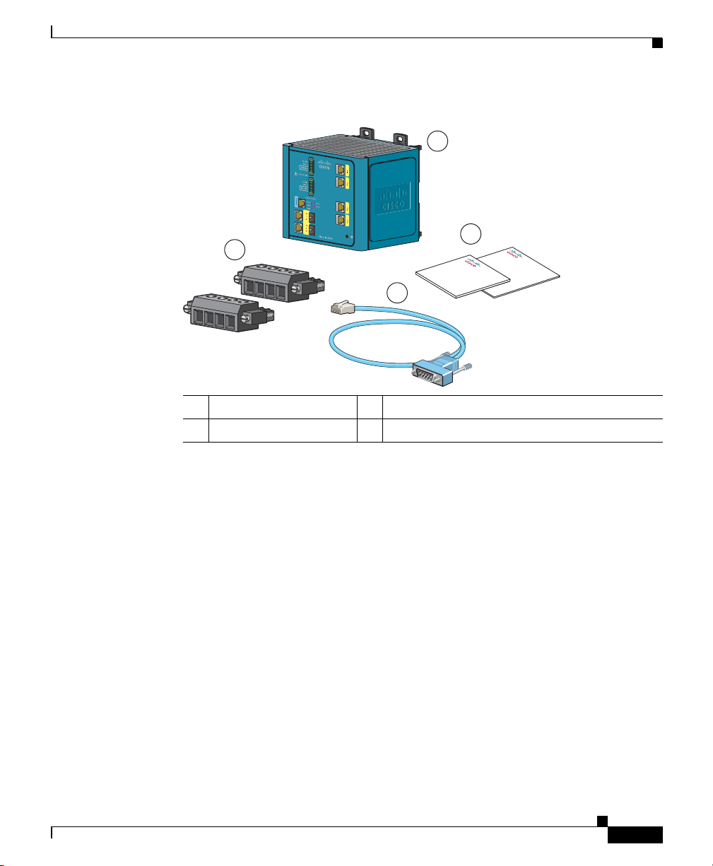
Figure 1 Cisco IE 3000 Shipping Box Contents
3
V
V
RT
A
A
1 Cisco IE 3000 switch
2 Documentation 4 Console cable (RJ-45-to-DB-9 adapter cable)
1. The Cisco IE-3000-4TC is shown as an example. Your switch model might look different.
1
2
Ci
s
co IE
Do
c
3
ume
t
i
on
201876
0
0
0 S
n
t
a
witch
tio
n
D
oc
um
ent
C
RT
A
A
D
a
4
1
3 Power and relay connectors
Connecting Expansion Modules
The switch can operate as a standalone device with Fast Ethernet ports. You can
increase the number of Fast Ethernet ports by connecting the Cisco
IEM-3000-8TM or the Cisco IEM-3000-8FM expansion module. You can also
install two expansion modules. Depending on the mix of switches and expansion
modules, you can have up to 24 Fast Ethernet ports. For more information about
the different combinations of the switch and expansion modules, see the
Cisco IE 3000 Switch Hardware Installation Guide on Cisco.com.
The switch expansion modules are optional and do not ship with the switch. You
need to order these separately.
Cisco IE 3000 Switch Getting Started Guide
OL-16234-01
3
Page 4
Cisco IE 3000 Switch Getting Started Guide
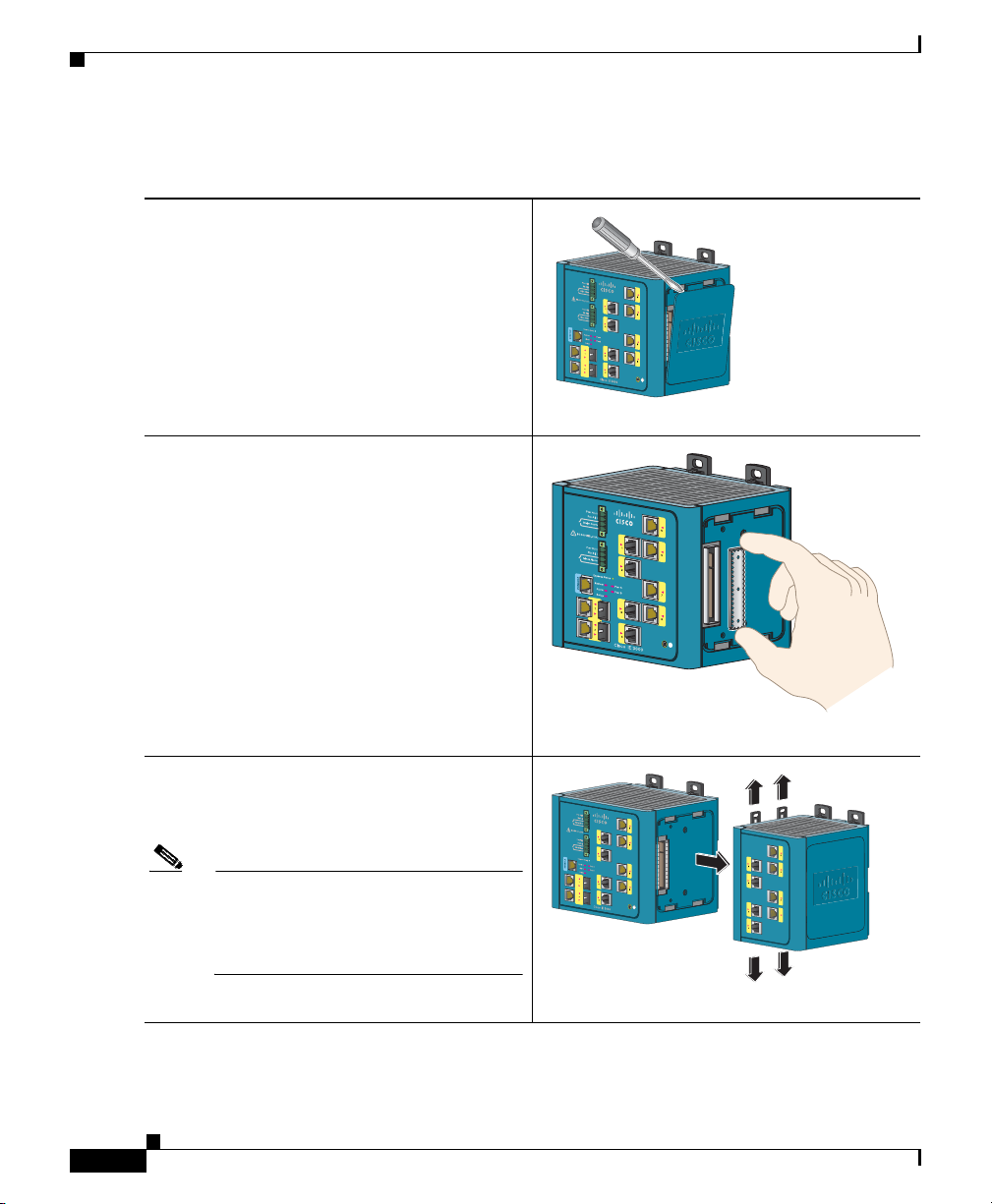
Follow these steps to connect the expansion modules to the switch.
Step 1
Step 2
Step 3
Remove the right side panel by firmly
grasping both sides in the middle and pulling
it outward. If necessary, use a flat-blade
screwdriver to pry open the side panel.
Remove the EMI protective cover from the
connector.
Push the upper module latches up and the
lower module latches down, and then slide the
switch and module together.
202334
3759
20
Note If you are installing a Cisco
IEM-3000-8TM module and a Cisco
IEM-3000-8FM module, install the
Cisco IEM-3000-8TM first.
Cisco IE 3000 Switch Getting Started Guide
4
202335
OL-16234-01
Page 5
Cisco IE 3000 Switch Getting Started Guide
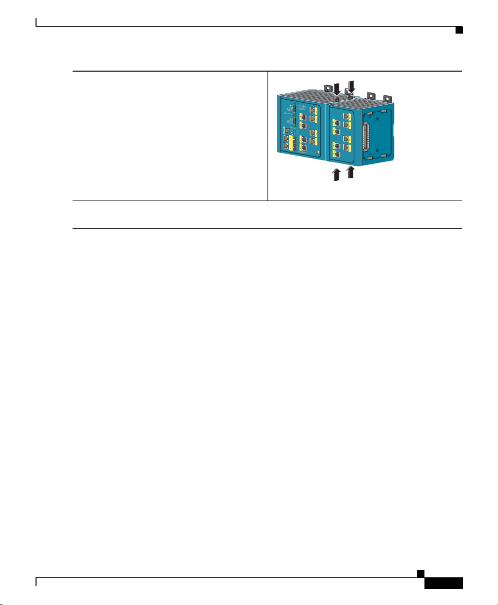
Step 4
Push in the upper and lower module latches to
secure the module to the switch.
Step 5
If you are installing a second module, repeat Step 2 to Step 3, but secure the second module
to the right side of the first module.
Running Express Setup
When you first set up the switch, you should use Express Setup to enter the initial
IP information. Doing this enables the switch to connect to local routers and the
Internet. You can then access the switch through the IP address for additional
configuration.
You need this equipment to set up the switch:
• A PC with Windows 2000, Windows Vista, Windows 2003 or XP installed.
202336
OL-16234-01
• A web browser (Internet Explorer 6.0, Internet Explorer 7.0, or Firefox 2.0)
with JavaScript enabled.
• A straight-through Category 5 Ethernet cable to connect your PC to the
switch.
Disable any pop-up blockers or proxy settings in your browser software and any
wireless client running on your PC.
Cisco IE 3000 Switch Getting Started Guide
5
Page 6
Cisco IE 3000 Switch Getting Started Guide
Express Setup
System
Alarm
Setup
Pwr A
Pwr B
To run Express Setup:
Step 1
Step 2
Step 3
Step 4
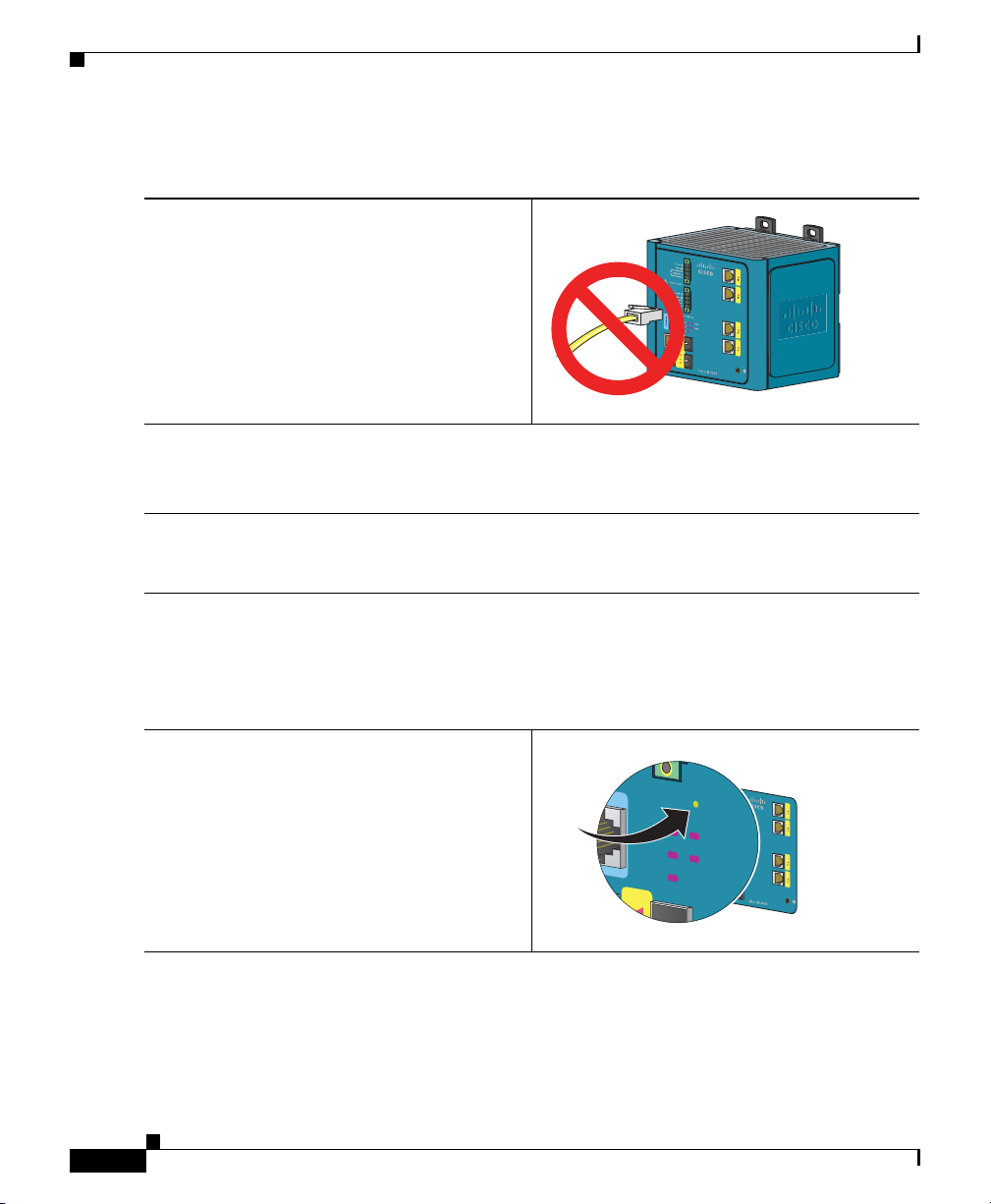
Step 5
Make sure that nothing is connected to the
switch.
During Express Setup, the switch acts as a
DHCP server. If your PC has a static IP
address, change your PC settings before you
begin to temporarily use DHCP.
201873
Connect power to the switch.
See the wiring instructions in the “Grounding the Switch” section on page 17 and the “Wiring
the DC Power Source” section on page 18.
When the switch powers on, it begins the power-on self-test (POST). During POST, the
System LED blinks while a series of tests verify that the switch functions properly. Wait for
the switch to complete POST, which takes approximately 1 minute.
Make sure that POST has completed by verifying that the System LED is solid green. If the
switch has not been configured, the Setup LED blinks green. If the Setup LED stops blinking,
you can still continue with the next step.
If the switch fails POST, the System LED turns red. See the “In Case of Difficulty” section
on page 25 if your switch fails POST.
Press the Express Setup button. This button is
recessed behind the front panel, so you can
use a simple tool, such as a paper clip.
When you press the Express Setup button, a
switch port LED begins blinking green.
6
Cisco IE 3000 Switch Getting Started Guide
2
OL-16234-01
201877
Page 7
Cisco IE 3000 Switch Getting Started Guide
Step 6
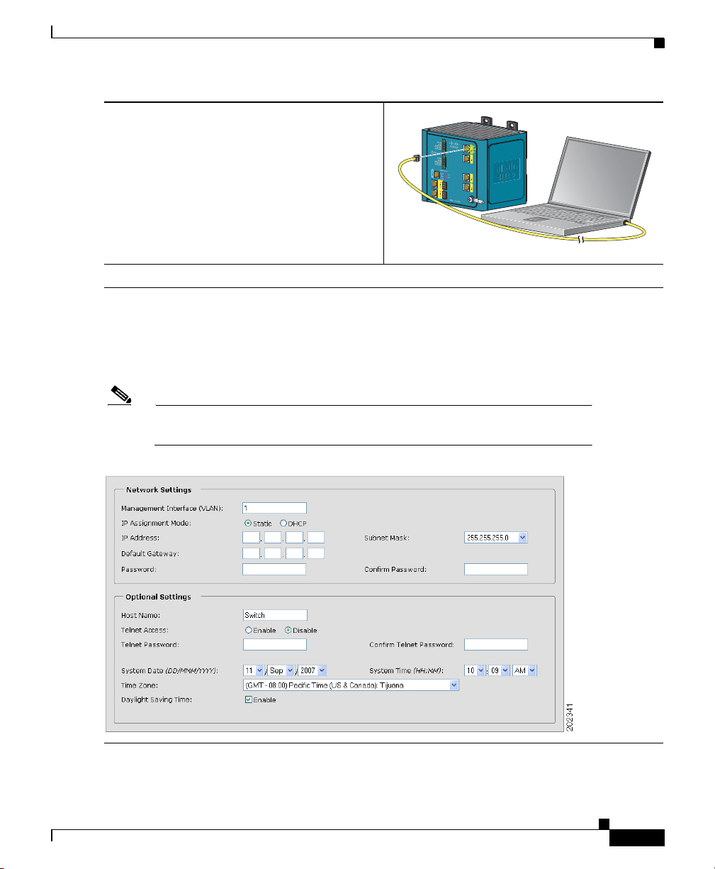
Step 7
Step 8
Connect a Category 5 Ethernet cable (not
provided) from the blinking switch port to the
Ethernet port on your PC.
1
The port LEDs on your PC and the switch
blink green while the switch configures the
connection.
When the Setup LED turns solid green, start a browser session on the PC.
The Express Setup window automatically appears. If the window does not appear, verify that
any proxy settings or pop-up blockers are disabled on your browser and that any wireless
client is disabled on your PC. You might also need to enter a URL in your browser, such as
Cisco.com or another well-known website. If you need help, see the “In Case of Difficulty”
section on page 25.
Note If the switch has been previously configured, the device manager page appears. You
can use it to change the switch IP address.
201879
OL-16234-01
Cisco IE 3000 Switch Getting Started Guide
7
Page 8

Cisco IE 3000 Switch Getting Started Guide
Step 9
Step 10
Enter the network settings. All entries must be in English letters and Arabic numbers.
• Management Interface (VLAN): We recommend using the default, VLAN 1. The
management VLAN establishes an IP connection to the switch.
• IP Assignment Mode: We recommend using the default, Static, which means that the
switch always has the IP address that you assign. Use the DHCP setting when you want
the switch to automatically obtain an IP address from a DHCP server.
• IP Address: Enter the IP address for the switch. Later, you can use the IP address to
access the switch through the device manager.
• Subnet Mask: Select a mask from the drop-down list.
• Default Gateway: Enter the IP address of the router.
• Password: Enter a password. The password can be from 1 to 25 alphanumeric characters,
can start with a number, is case sensitive, allows embedded spaces, but does not allow
spaces at the beginning or end. In the Confirm Password field, enter the password again.
For more information about the network settings, click Help on the toolbar.
Enter the Optional Settings now, or enter them later by using the device manager interface:
• Enter a Host Name for the switch.
• Select Enable or Disable for Telnet access. If enabled, enter and confirm the Telnet
password in the Password fields.
• The date and time fields are populated from your PC.
• Click Enable to use Daylight Saving Time.
Step 11
Step 12
8
For more information about the optional settings, click Help on the toolbar.
Click Submit to save the information that you entered and to finish the basic configuration.
You have completed the initial switch setup. If you click Cancel, the fields are cleared, and
you can start over.
Turn off DC power at the source, disconnect all cables to the switch, and install the switch in
your network. See the “Managing the Switch” section on page 9 for information about
configuring and managing the switch.
Cisco IE 3000 Switch Getting Started Guide
OL-16234-01
Page 9

Cisco IE 3000 Switch Getting Started Guide
Refreshing the PC IP Address
After you complete Express Setup, you should refresh the PC IP address:
• For a dynamically assigned IP address, disconnect the PC from the switch,
and reconnect the PC to the network. The network DHCP server assigns a new
IP address to the PC.
• For a statically assigned IP address, change it to the previously configured
IP address.
Managing the Switch
After you complete Express Setup and install the switch in your network, use the
device manager or other management options described in these sections for
additional configuration:
• Using the Device Manager, page 9
• Downloading Cisco Network Assistant, page 10
• Command-Line Interface, page 10
• Other Management Options, page 11
Using the Device Manager
The simplest way to manage the switch is by using the device manager that is in
the Cisco IOS image. The device manager has a web interface that simplifies
configuration and monitoring of the switch. You can access the device manager
from anywhere in your network through a web browser.
Follow these steps:
1. Launch a web browser on your PC or workstation.
2. Enter the switch IP address in the web browser, and press Enter. The device
manager page appears.
OL-16234-01
Cisco IE 3000 Switch Getting Started Guide
9
Page 10

3. Use the device manager to perform basic switch configuration and
monitoring. See the device manager online help for more information.
4. For more advanced configuration, download and run the Cisco Network
Assistant, which is described in the next section.
Downloading Cisco Network Assistant
Cisco Network Assistant is a software program that you download from
Cisco.com and run on your PC. It offers advanced options for configuring and
monitoring multiple devices, including switches, switch clusters, switch stacks,
routers, and access points. Network Assistant is free—there is no charge to
download, install, or use it.
Follow these steps:
1. Go to this Web address: http://www.cisco.com/go/NetworkAssistant.
You must be a registered Cisco.com user, but you need no other access
privileges.
2. Find the Network Assistant installer.
3. Download the Network Assistant installer, and run it. (You can run it directly
from the Web if your browser offers this choice.)
4. When you run the installer, follow the displayed instructions. In the final
panel, click Finish to complete the Network Assistant installation.
Cisco IE 3000 Switch Getting Started Guide
See the Network Assistant online help and the getting started guide for more
information.
Command-Line Interface
You can manage the switch from the command-line interface (CLI) by connecting
your PC directly to the switch console port or to an Ethernet port. This procedure
explains how to access the CLI through the console port.
Cisco IE 3000 Switch Getting Started Guide
10
OL-16234-01
Page 11

Cisco IE 3000 Switch Getting Started Guide
Using the Switch Console Port:
Follow these steps:
1. Connect the supplied RJ-45-to-DB-9 adapter cable (console cable) to the
standard 9-pin serial port on the PC. Connect the other end of the cable to the
console port on the switch.
2. Start a terminal-emulation program on the PC.
3. Configure the PC terminal emulation software for 9600 bits per second, 8 data
bits, no parity, 1 stop bit, and no flow control.
Use the CLI to enter commands to configure the switch. See the software
configuration guide and the command reference for more information.
Other Management Options
You can use Simple Network Management Protocol (SNMP) management
applications such as CiscoWorks Small Network Management Solution (SNMS)
and HP OpenView to configure and manage the switch. You also can manage it
from an SNMP-compatible workstation that is running platforms such as HP
OpenView or SunNet Manager.
See the “Accessing Online Help” section on page 27 for a list of supporting
documents.
Installing the Switch
These sections explain how to install the switch on a DIN rail or in a rack. Refer
to the switch hardware guide for instructions on mounting the switch on a wall:
• Equipment That You Supply, page 12
• Before You Begin, page 12
• Installation Warning Statements, page 13
• Mounting the Switch to a DIN Rail or to the Rack Adapter, page 16
• Grounding the Switch, page 17
• Wiring the DC Power Source, page 18
OL-16234-01
Cisco IE 3000 Switch Getting Started Guide
11
Page 12

• Attaching the Power and Relay Connector, page 20
• Optional Procedures, page 21
Equipment That You Supply
Obtain these necessary tools and equipment:
• Ratcheting torque flathead screwdriver that exerts up to 15-inch pound (in-lb)
of pressure
• Ring terminal lug (such as Thomas & Bett part number 10RC6 or equivalent)
• Crimping tool (such as Thomas & Bett part number WT2000, ERG-2001, or
equivalent)
• 10- to 12-gauge copper ground wire (such as Belden part number 9912 or
equivalent)
• For DC power connections, use UL- and CSA-rated style 1007 or 1569
twisted-pair copper appliance wiring material (AWM) wire (such as Belden
part number 9318)
• Wire-stripping tools for stripping 10-, 12-, and 18-gauge wires
Cisco IE 3000 Switch Getting Started Guide
• For rack-mounting, a number-2 Phillips screwdriver
• A flat-blade screwdriver
Before You Begin
When you determine where to install the switch, verify that these guidelines
are met:
• Operating environment is within the range in the switch hardware installation
• Clearance to front and rear panels meets these conditions:
Cisco IE 3000 Switch Getting Started Guide
12
guide.
–
Front-panel LEDs can be easily read.
–
Access to ports is sufficient for unrestricted cabling.
–
Front-panel direct current (DC) power and relay connector is within
reach of the connection to the DC power source.
OL-16234-01
Page 13

Cisco IE 3000 Switch Getting Started Guide
• Airflow around the switch and through the vents is unrestricted. To prevent
the switch from overheating, these must be the minimum clearances:
–
Top and bottom: 4.13 in. (105 mm)
–
Left and right: 3.54 in. (90 mm)
–
Front: 2.56 in. (65 mm)
• Temperature surrounding the unit does not exceed 140°F (60°C), the
maximum ambient temperature of the switch.
Note When the switch is installed in an industrial enclosure, the temperature within the
enclosure is greater than normal room temperature outside the enclosure.
• Cabling is away from sources of electrical noise, such as radios, power lines,
and fluorescent lighting fixtures.
• This product is grounded to a bare metal surface, such as a ground bus, a
grounded DIN rail, or a grounded bare rack. Use a zinc-plated,
yellow-chromate steel DIN rail to assure proper grounding. The use of other
materials (such as aluminum, plastic, and so on) that can corrode, oxidize, or
are poor conductors can result in improper or intermittent grounding. When
grounding to a DIN rail, secure the DIN rail to the mounting surface
approximately every 7.8 in. (200 mm), and use appropriate end-anchors.
Installation Warning Statements
Warning
Warning
OL-16234-01
Before performing any of the following procedures, ensure that power is
removed from the DC circuit.
This product relies on the building’s installation for short-circuit (overcurrent)
protection. Ensure that the protective device is rated not greater than: 5A.
Statement 1005
Statement 1003
Cisco IE 3000 Switch Getting Started Guide
13
Page 14

Cisco IE 3000 Switch Getting Started Guide
Warning
Warning
Warning
Warning
Warning
This unit is intended for installation in restricted access areas. A restricted
access area can be accessed only through the use of a special tool, lock and
key, or other means of security.
Statement 1017
This equipment must be grounded. Never defeat the ground conductor or
operate the equipment in the absence of a suitably installed ground conductor.
Contact the appropriate electrical inspection authority or an electrician if you
are uncertain that suitable grounding is available.
Statement 1024
Only trained and qualified personnel should be allowed to install, replace, or
service this equipment.
Statement 1030
To prevent the system from overheating, do not operate it in an area that
exceeds the maximum recommended ambient temperature of:
140°F (60°C)
Statement 1047
This equipment is supplied as “open type” equipment. It must be mounted
within an enclosure that is suitably designed for those specific environmental
conditions that will be present and appropriately designed to prevent personal
injury resulting from accessibility to live parts. The interior of the enclosure
must be accessible only by the use of a tool.
14
The enclosure must meet IP 54 or NEMA type 4 minimum enclosure rating
Warning
standards.
This equipment is intended to be grounded to comply with emission and
Statement 1063
immunity requirements. Ensure that the switch functional ground lug is
connected to earth ground during normal use.
Cisco IE 3000 Switch Getting Started Guide
Statement 1064
OL-16234-01
Page 15

Cisco IE 3000 Switch Getting Started Guide
Warning
When used in a Class I, Division 2, hazardous location, this equipment must be
mounted in a suitable enclosure with proper wiring method, for all power, input
and output wiring, that complies with the governing electrical codes and in
accordance with the authority having jurisdiction over Class I, Division 2
installations.
Warning
To prevent airflow restriction, allow clearance around the ventilation openings
to be at least: 4.13 in. (10.5 cm)
Caution This equipment is suitable for use in Class I, Division 2, Groups A, B, C, D, or
Statement 1066
Statement 1076
only nonhazardous locations.
Caution Connect the unit only to a Class 2 DC power source.
OL-16234-01
Cisco IE 3000 Switch Getting Started Guide
15
Page 16

Cisco IE 3000 Switch Getting Started Guide
Mounting the Switch to a DIN Rail or to the Rack Adapter
Follow these steps to mount the switch on a DIN rail or in a rack.
Step 1
Step 2
Step 3
If you are mounting the switch in a rack,
first secure the Cisco IE 3000 rack adapter
to the rack.
If mounting on a DIN rail, omit this step.
202337
Insert a flat-head screwdriver in the space
next to the tab, and turn the screw driver to
release the latch and push it out.
202937
If you are using a 15 mm DIN rail, rotate all
feet to the extended positions. Otherwise,
rotate the feet to the recessed positions.
Foot
Latch
202338
16
Cisco IE 3000 Switch Getting Started Guide
OL-16234-01
Page 17

Cisco IE 3000 Switch Getting Started Guide
Step 4
Position the rear panel of the switch directly
in front of the DIN rail, making sure that the
DIN rail fits in the space between the two
latches.
Step 5
Push the DIN rail latches in after the switch is over the DIN rail to secure the switch to the
rail. You hear a click when the latches are completely locked.
Step 6
Connect power to the switch.
See the wiring instructions in the “Grounding the Switch” section on page 17 and the
“Wiring the DC Power Source” section on page 18.
Grounding the Switch
Follow these steps to connect the switch to a protective ground.
Warning
This equipment must be grounded. Never defeat the ground conductor or
operate the equipment in the absence of a suitably installed ground conductor.
Contact the appropriate electrical inspection authority or an electrician if you
are uncertain that suitable grounding is available.
DIN rail
202339
Statement 1024
Step 1
Step 2
OL-16234-01
Use a standard Phillips screwdriver or a ratcheting torque screwdriver with a Phillips head to
remove the ground screw from the front panel of the switch. Store the ground screw for later
use.
Use a wire stripping tool to strip the 10- to
12-gauge ground wire to 0.5 inch (12.7 mm)
± 0.02 inch (0.5 mm).
0.5 inch (12.7 mm)
Cisco IE 3000 Switch Getting Started Guide
119516
17
Page 18

Cisco IE 3000 Switch Getting Started Guide
Step 3
Step 4
Step 5
Step 6
Step 7
Insert the ground wire into the ring terminal
lug, and using a crimping tool, crimp the ring
terminal to the wire.
119626
Slide the ground screw from Step 1 through the ring terminal.
Insert the ground screw into the ground-screw
opening on the front panel.
329
202
Use a ratcheting torque screwdriver to tighten the ground screw and ring terminal lug to the
switch front panel to 8.5 in-lb, the maximum recommended torque.
Attach the other end of the ground wire to a grounded bare metal surface, such as a ground
bus, a grounded DIN rail, or a grounded bare rack.
Wiring the DC Power Source
Follow these steps to prepare the DC power cable.
Warning
Cisco IE 3000 Switch Getting Started Guide
18
Before performing any of the following procedures, ensure that power is
removed from the DC circuit.
Statement 1003
OL-16234-01
Page 19

Cisco IE 3000 Switch Getting Started Guide
Step 1
Step 2
Step 3
Step 4
Step 5
Warning
This product relies on the building’s installation for short-circuit (overcurrent)
protection. Ensure that the protective device is rated not greater than: 5A.
Statement 1005
Warning
Only trained and qualified personnel should be allowed to install, replace, or
service this equipment.
Statement 1030
Locate the power and relay connector.
V
RT
A
A
201815
Identify the positive and return DC power connections on the connector. The positive DC
power connection is labeled V, and the return is the adjacent connection labeled RT.
Measure a strand of twisted-pair copper wire (18- to 20-AWG) long enough to connect to the
DC power source.
Using an 18-gauge wire-stripping tool, strip
each of the two wires to 0.25 inch (6.3 mm) ±
0.02 inch (0.5 mm). Do not strip more than
.27 inch (6.6 mm)
119591
0.27 inch (6.8 mm) of insulation from the
wire. Stripping more than the recommended
amount of wire can leave exposed wire from
the connector after installation.
Insert the exposed part of the positive wire
into the connection labeled V and the exposed
part of the return wire into the connection
VRTA A
labeled RT. Make sure that you cannot see any
wire lead. Only wire with insulation should
extend from the connector.
V
RT
202330
Step 6
OL-16234-01
Use a ratcheting torque flathead screwdriver to torque the power and relay connector captive
screws (above the installed wire leads) to 2 in-lb, the maximum recommended torque.
Cisco IE 3000 Switch Getting Started Guide
19
Page 20

Cisco IE 3000 Switch Getting Started Guide
Step 7
Connect the other end of the positive wire (the one connected to V) to the positive terminal
on the DC power source, and connect the other end of the return wire (the one connected to
RT) to the return terminal on the DC power source.
Step 8
When you are testing the switch, one power connection is sufficient. If you are installing the
switch and are using a second power source, repeat Step 3 through Step 7 using a second
power and relay connector.
Attaching the Power and Relay Connector
Follow these steps to connect the DC power and relay connector to the switch:
Caution The input voltage source of the alarm circuits must be an isolated source and
limited to less than or equal to 30 VDC, 1 A.
Step 1
Insert the power and relay connector into the
Pwr A receptacle on the switch front panel.
VRTA A
Step 2
20
202332
Use a flathead screwdriver to tighten the captive screws on the sides of the power and relay
connector.
Cisco IE 3000 Switch Getting Started Guide
OL-16234-01
Page 21

Cisco IE 3000 Switch Getting Started Guide
Step 3
Optionally, insert a second power and relay
connector into the Pwr B receptacle on the
switch front panel.
Step 4
Use a flathead screwdriver to tighten the captive screws on the sides of the second power and
relay connector.
Optional Procedures
For detailed instructions on these procedures, see the Cisco IE 3000 Switch
Hardware Installation Guide on Cisco.com.
• Wiring the external alarm relays
• Connecting the switch to the optional PWR-IE3000-AC power converter
• Mounting the switch on the wall
• Installation in a hazardous environment
VRTA A
VRTA A
VRTA A
202333
Connecting to the Switch Ports
These sections describe how to connect to the switch ports, the SFP module ports,
and the dual-purpose ports. For additional cabling information, see the Cisco IE
3000 Switch Hardware Installation Guide on Cisco.com.
• Connecting to 10/100 and 10/100/1000 Ports, page 22
• Installing SFP Modules and Connecting to Ports, page 23
• Connecting to Dual-Purpose Ports, page 24
• Connecting to 100BASE-FX Ports, page 24
• Verifying Port Connectivity, page 24
Cisco IE 3000 Switch Getting Started Guide
OL-16234-01
21
Page 22

Connecting to 10/100 and 10/100/1000 Ports
Follow these steps:
Cisco IE 3000 Switch Getting Started Guide
Step 1
Step 2
When you connect these switches to any
Ethernet-enabled communication devices,
insert a straight-through twisted four-pair,
10/100/1000
Category 5 cable in a switch 10/100 or
10/100/1000 port. Use a twisted four-pair,
Category 5 cable when you connect to other
switches, hubs, or repeaters.
10/100
Insert the other cable end into an RJ-45 connector on the other device.
For simplified cabling, the automatic medium-dependent interface crossover
(auto-MDIX) feature is enabled by default on the switch. With auto-MDIX
enabled, the switch detects the required cable type for copper Ethernet
connections and configures the interfaces accordingly. Therefore, you can use
either a crossover or a straight-through cable for connections to a switch 10/100
or 10/100/1000 Ethernet port, regardless of the type of device on the other end of
the connection.
2
202325
22
Cisco IE 3000 Switch Getting Started Guide
OL-16234-01
Page 23

Cisco IE 3000 Switch Getting Started Guide
Installing SFP Modules and Connecting to Ports
Follow these steps:
Step 1
Step 2
Step 3
Grasp the module on the sides, and insert it
into the switch slot until you feel the
connector snap into place.
202326
Insert an appropriate cable into the module
port.
202327
Insert the other cable end into the other device.
For a list of supported modules, see the release notes on Cisco.com. For detailed
instructions on installing, removing, and connecting to SFP modules, see the
documentation that came with the SFP module.
OL-16234-01
Caution Removing and installing an SFP module can shorten its useful life. Do not remove
and insert SFP modules more often than is absolutely necessary.
Cisco IE 3000 Switch Getting Started Guide
23
Page 24

Connecting to Dual-Purpose Ports
Only one port on a dual-purpose port can be active at a time. If both ports are
connected, the SFP module port has priority.
Follow these steps:
Cisco IE 3000 Switch Getting Started Guide
Step 1
Step 2
Insert either an RJ-45 connector to the 10/100/1000 port (see the “Connecting to 10/100 and
10/100/1000 Ports” section on page 22), or install an SFP module into the SFP module slot,
and connect a cable to the SFP module port. (See the “Installing SFP Modules and Connecting
to Ports” section on page 23.)
Insert the other cable end into the other device.
Connecting to 100BASE-FX Ports
Follow these steps:
Step 1
Step 2
Insert an LC cable into the 100BASE-FX port
of a Cisco IEM-3000-8FM expansion module.
Insert the other cable end into the other device.
202328
Verifying Port Connectivity
After you connect to the switch port and another device, the port LED turns amber
while the switch establishes a link. This process takes about 30 seconds, and then
the LED turns green when the switch and the target device have an established
link. If the LED is off, the target device might not be turned on, there might be a
cable problem, or there might be a problem with the adapter installed in the
target device.
Cisco IE 3000 Switch Getting Started Guide
24
OL-16234-01
Page 25

Cisco IE 3000 Switch Getting Started Guide
In Case of Difficulty
See these sections if you have difficulty setting up your switch:
• Troubleshooting Express Setup, page 25
• Resetting the Switch, page 26
• Accessing Online Help, page 27
• For More Information, page 27
Troubleshooting Express Setup
Help with the initial switch configuration is provided here. For additional
assistance, see the online documentation at Cisco.com.
Checklist Recommendation
Was the SETUP LED blinking
when you pressed the Express Setup
button?
Did you connect your PC to the
wrong switch port?
Did you start a browser session on
your PC before the SETUP LED
was solid green?
Did you start a browser session on
your PC and the set-up page did not
appear?
Did you have a pop-up blocker
running on your PC when you
connected to the switch port?
Did you have proxy settings
enabled in your browser software
when you connected to the switch
port?
If no, or you are not sure, restart the switch. Make sure that the
SETUP LED is blinking when you press the Express Setup
button.
Verify that you are connected to the switch port with the blinking
LED.
If yes, or you are not sure, restart the switch, and repeat the
Express Setup procedure.
If the window does not appear, enter a URL in your browser, such
as Cisco.com or another well-known website.
If yes, disconnect the cable from the switch port, disable the
pop-up blocker, press the Express Setup button, and reconnect
the cable to the blinking Ethernet port.
If yes, disconnect the cable from the switch port, disable the
proxy settings, press the Express Setup button, and reconnect the
cable to the blinking Ethernet port.
OL-16234-01
Cisco IE 3000 Switch Getting Started Guide
25
Page 26

Checklist Recommendation
Did you have a wireless client
running on your PC when you
connected to the switch port?
Do you need to change the switch IP
address after you have already
completed the initial setup?
If yes, disconnect the cable from the switch port, disable the
wireless client, press the Express Setup button, and reconnect the
cable to the blinking Ethernet port.
Go to the Configure > Express Setup device manager screen to
change the switch IP address. For more information about
changing the switch IP address, see the switch configuration
guide online at Cisco.com.
Resetting the Switch
Follow these steps to return your switch to the factory default settings. These are
reasons why you might want to reset the switch:
• You installed the switch in your network and cannot connect to it because you
assigned the wrong IP address.
• You want to clear all configurations from the switch and assign a new IP
address.
• You want to reset the password on the switch.
Cisco IE 3000 Switch Getting Started Guide
26
Caution Resetting the switch deletes the configuration and reboots the switch.
To reset the password on the switch:
1. Power off the switch.
2. Power on the switch, and at the same time, press and hold down the Express
Setup button until all the system LEDs turn red.
3. Release the Express Setup button, and the switch continues to boot.
After the switch restarts, continue to run Express Setup.
Cisco IE 3000 Switch Getting Started Guide
OL-16234-01
Page 27

Cisco IE 3000 Switch Getting Started Guide
Accessing Online Help
First look for a solution to your problem in the troubleshooting section of the
switch hardware installation guide or the switch software configuration guide on
Cisco.com. You can also access the Cisco Technical Support and Documentation
website for a list of known hardware problems and extensive troubleshooting
documentation.
For More Information
For more information about the switch, see these documents on Cisco.com:
• Cisco IE 3000 Switch Hardware Installation Guide. This guide provides
complete hardware descriptions and detailed installation procedures.
• Regulatory Compliance and Safety Information for the Cisco IE 3000 Switch.
This guide contains agency approvals, compliance information, and
translated warning statements.
• Release Notes for the Cisco IE 3000 Switch.
OL-16234-01
• Cisco IE 3000 Switch Software Configuration Guide. This guide provides a
product overview and detailed descriptions and procedures of the switch
software features.
• Cisco IE 3000 Switch Command Reference. This reference provides detailed
descriptions of the Cisco IOS commands specifically created or modified for
the switch.
• Cisco IE 3000 Switch System Message Guide. This guide provides
descriptions of the system messages specifically created or modified for the
switch.
• Device manager online help (available on the switch).
• Cisco Small Form-Factor Pluggable Modules Installation Notes.
Cisco IE 3000 Switch Getting Started Guide
27
Page 28

Cisco IE 3000 Switch Getting Started Guide
Obtaining Documentation and Submitting a
Service Request
For information on obtaining documentation, submitting a service request, and
gathering additional information, see the monthly What’s New in Cisco Product
Documentation, which also lists all new and revised Cisco technical
documentation, at:
http://www.cisco.com/en/US/docs/general/whatsnew/whatsnew.html
Subscribe to the What’s New in Cisco Product Documentation as a Really Simple
Syndication (RSS) feed and set content to be delivered directly to your desktop using
a reader application. The RSS feeds are a free service and Cisco currently supports
RSS version 2.0.
Cisco One-Year Limited Hardware Warranty Terms
There are special terms applicable to your hardware warranty and various services
that you can use during the warranty period. Your formal Warranty Statement,
including the warranties and license agreements applicable to Cisco software, is
available on Cisco.com. Follow these steps to access and download the Cisco
Information Packet and your warranty and license agreements from Cisco.com.
1. Launch your browser, and go to this URL:
28
http://www.cisco.com/univercd/cc/td/doc/es_inpck/cetrans.htm
The Warranties and License Agreements page appears.
2. To read the Cisco Information Packet, follow these steps:
a. Click the Information Packet Number field, and make sure that the part
number 78-5235-03C0 is highlighted.
b. Select the language in which you would like to read the document.
c. Click Go.
The Cisco Limited Warranty and Software License page from the
Information Packet appears.
d. Read the document online, or click the PDF icon to download and print
the document in Adobe Portable Document Format (PDF).
Cisco IE 3000 Switch Getting Started Guide
OL-16234-01
Page 29

Cisco IE 3000 Switch Getting Started Guide
Note You must have Adobe Acrobat Reader to view and print PDF files. You
can download the reader from Adobe’s website: http://www.adobe.com
3. To read translated and localized warranty information about your product,
follow these steps:
a. Enter this part number in the Warranty Document Number field:
78-10747-01C0
b. Select the language in which you would like to view the document.
c. Click Go.
The Cisco warranty page appears.
d. Read the document online, or click the PDF icon to download and print
the document in Adobe Portable Document Format (PDF).
You can also contact the Cisco service and support website for assistance:
http://www.cisco.com/public/Support_root.shtml.
OL-16234-01
Duration of Hardware Warranty
One (1) Year
Replacement, Repair, or Refund Policy for Hardware
Cisco or its service center will use commercially reasonable efforts to ship a
replacement part within ten (10) working days after receipt of a Return Materials
Authorization (RMA) request. Actual delivery times can vary, depending on the
customer location.
Cisco reserves the right to refund the purchase price as its exclusive warranty
remedy.
Cisco IE 3000 Switch Getting Started Guide
29
Page 30

Cisco IE 3000 Switch Getting Started Guide
To Receive a Return Materials Authorization (RMA) Number
Contact the company from whom you purchased the product. If you purchased the
product directly from Cisco, contact your Cisco Sales and Service Representative.
Complete the information below, and keep it for reference.
Company product purchased from
Company telephone number
Product model number
Product serial number
Maintenance contract number
30
Cisco IE 3000 Switch Getting Started Guide
OL-16234-01
Page 31

Cisco IE 3000 Switch Getting Started Guide
OL-16234-01
Cisco IE 3000 Switch Getting Started Guide
31
Page 32

Cisco IE 3000 Switch Getting Started Guide
CCDE, CCENT, Cisco Eos, Cisco Lumin, Cisco StadiumVision, the Cisco logo, DCE, and Welcome to the Human
Network are trademarks; Changing the Way We Work, Live, Play, and Learn is a service mark; and Access Registrar,
Aironet, AsyncOS, Bringing the Meeting To You, Catalyst, CCDA, CCDP, CCIE, CCIP, CCNA, CCNP, CCSP,
CCVP, Cisco, the Cisco Certified Internetwork Expert logo, Cisco IOS, Cisco Press, Cisco Systems, Cisco Systems
Capital, the Cisco Systems logo, Cisco Unity, Collaboration Without Limitation, EtherFast, EtherSwitch, Event
Center, Fast Step, Follow Me Browsing, FormShare, GigaDrive, HomeLink, Internet Quotient, IOS, iPhone, iQ
Expertise, the iQ logo, iQ Net Readiness Scorecard, iQuick Study, IronPort, the IronPort logo, LightStream, Linksys,
MediaTone, MeetingPlace, MGX, Networkers, Networking Academy, Network Registrar, PCNow, PIX,
PowerPanels, ProConnect, ScriptShare, SenderBase, SMARTnet, Spectrum Expert, StackWise, The Fastest Way to
Increase Your Internet Quotient, TransPath, WebEx, and the WebEx logo are registered trademarks of
Cisco Systems, Inc. and/or its affiliates in the United States and certain other countries.
All other trademarks mentioned in this document or Website are the property of their respective owners. The use of
the word partner does not imply a partnership relationship between Cisco and any other company. (0804R)
Any Internet Protocol (IP) addresses used in this document are not intended to be actual addresses. Any examples,
command display output, and figures included in the document are shown for illustrative purposes only. Any use of
actual IP addresses in illustrative content is unintentional and coincidental.
32
Cisco IE 3000 Switch Getting Started Guide
OL-16234-01
 Loading...