

Cisco Gigabit Switch Router Cisco 12008, GSR8/10-40-UPG= - 12008 Router -AnyLAN, Serial Installation And Configuration Manual
Page 1

Cisco 12008 Gigabit Switch
Router Installation and
Configuration Guide
Corporate Headquarters
Cisco Systems , In c.
170 West Tasman Drive
San Jose, CA 95134-1706
USA
World Wide Web URL:
http://www.cisco.com
Tel:
408 526-4000
800 553-NETS (6387)
Fax:
408 526-4100
Customer Order Number: DOC-12008GSR-ICG=
Text Part Number: 78-4953-03
Page 2

THE SPECIFICATIONS AND INFORMATION REGARDING THE PRODUCTS IN THIS MANUAL ARE SUBJECT TO CHANGE WITHOUT
NOTICE. ALL STATEMENTS, INFORMATION, AND RECOMMENDATIONS IN THIS MANUAL ARE BELIEVED TO BE ACCURATE BUT ARE
PRESENTED WITHOUT WARRANTY OF ANY KIND, EXPRESS OR IMPLIED. USERS MUST TAKE FULL RESPONSIBILITY FOR THEIR
APPLICATION OF ANY PRODUCTS.
THE SOFTWARE LICENSE AND LIMITED WARRANTY FOR THE ACCOMPANYING PRODUCT ARE SET FORTH IN THE INFORMATION
PACKET THAT SHIPPED WITH THE PRODUCT AND ARE INCORPORATED HEREIN BY THIS REFERENCE. IF YOU ARE UNABLE TO
LOCATE THE SOFTWARE LICENSE OR LIMITED WARRANTY, CONTACT YOUR CISCO REPRESENTATIVE FOR A COPY.
The following information is for FCC compliance of Class A devices: This equipment has been tested and found to comply with the limits for a Class A
digital device, pursuant to part 15 of the FCC rules. These limits are designed to provide reasonable protection against harmful interference when the
equipment is operated in a commercial environment. This equipment generates, uses, and can radiate radio-frequency energy and, if not installed and used
in accordance with the instruction manual, may cause harmful interference to radio communications. Operation of this equipment in a residential area is
likely to cause harmful interference, in which case user s will be requir ed to corr ect the inter ferenc e at thei r own expens e.
The following information is for FCC compliance of Class B devices: The equipment described in this manual generates and may radiate radio-frequency
energy. If it is not installed in accordance with Cisco’s installation instructions, it may cause interference with radio and television reception. This equipment
has been tested and found to comply with the limits for a Class B digital device in accordance with the specifications in part 15 of the FCC rules. These
specifications are designed to provide reasonable protection against such interference in a residential installation. However, there is no guarantee that
interference will not occur in a particular insta llation.
You can determine whether your equipment is causing interference by turning it off. If the interference stops, it was probably caused by the Cisco equipment
or one of its peripheral devices. If the equipment causes interference to radio or television reception, tr y to c orrect t he interference by using one or more of
the following measures:
• Turn the television or radio antenna until the interference stops.
• Move the equipment to one side or the other of the television or radio.
• Move the equipment farther away from the television or radio.
• Plug the equipment into an outlet that is on a different circuit from the television or radio. (That is, make certain the equipment and the television or radio
are on circuits controlled by different circuit breakers or fuses.)
Modifications to this product not authorized by Cisco Systems, Inc. could void the FCC approval and negate your authority to operate the product.
The following third-party software may be include d with your product and will be subject to the software license agreement:
CiscoWorks software and documentation are based in part on HP OpenView under license from the Hewlett-Packard Company. HP OpenView is a
trademark of the Hewlett-Packard Company. Copyright © 1992, 1993 Hewlett-Packard Company.
The Cisco implementation of TCP header compression is an adaptation of a program developed by the University of California, Berkeley (UCB) as part of
UCB’s public domain version of the UNIX operating system. All rights reserved. Copyright © 1981, Regents of the University of California.
Network Time Protocol (NTP). Copyright © 1992, David L. Mills. The University of Delaware makes no representations about the suitability of this
software for any purpose.
Point-to-Point Protocol. Copyright © 1989, Carnegie-Mellon University. All right s reserved. The name of the University may not be used to endorse or
promote products derived from this softwa re without s peci fic prior written permission.
The Cisco implementation of TN3270 is an adaptation of the TN3270, curses, and termcap programs developed by the University of California, Berkeley
(UCB) as part of UCB’s public domain version of the UNIX operating system. All rights reserved. Copyright © 1981-1988, Regents of the University of
California.
Cisco incorporates Fastmac and TrueView software and the RingRunner chip in some Token Ring products. Fastmac software is licensed to Cisco by Madge
Networks Limited, and the RingRunner chip is licensed to Cisco by Madge NV. Fastma c, Ring Ru nner, and TrueVie w are trade marks and in some
jurisdictions registered trademar ks of Ma dge Networks Limit e d. Copyright © 1995, Madge Networks Limited. All rights reserved.
XRemote is a trademark of Network Computing Devices, Inc. Copyright © 1989, Network Computing Devices, Inc., Mountain View, California. NCD
makes no representations about the suitability of this software for any purpose.
The X Window System is a trademark of the X Consortium, Cambridge, Massachusetts. All rights reserved.
Page 3

NOTWITHSTANDING ANY OTHER WARRANTY HEREIN, ALL DOCUMENT FILES AND SOFTWARE OF THESE SUPPLIERS ARE
PROVIDED “AS IS” WITH ALL FAULTS. CISCO AND THE ABOVE-NAMED SUPPLIERS DISCLAIM ALL WARRANTIES, EXPRESSED OR
IMPLIED, INCLUDING, WITHOUT LIMITATION, THOSE OF MERCHANTABILITY, FITNESS FOR A PARTICULAR PURPOSE AND
NONINFRINGEMENT OR ARISING FROM A COURSE OF DEALING, USAGE, OR TRADE PRACTICE.
IN NO EVENT SHALL CISCO OR ITS SUPPLIERS BE LIABLE FOR ANY INDIRECT, SPECIAL, CONSEQUENTIAL, OR INCIDENTAL
DAMAGES, INCLUDING, WITHOUT LIMITATION, LOST PROFITS OR LOSS OR DAMAGE TO DATA ARISING OUT OF THE USE OR
INABILITY TO USE THIS MANUAL, EVEN IF CISCO OR ITS SUPPLIERS HAVE BEEN ADVISED OF THE POSSIBILITY OF SUCH DAMAGES.
CCSP, the Cisco Square Bridge logo, Cisco Unity, Follow Me Browsing, FormShare, and StackWise are trademarks of Cisco Systems, Inc.; Changing the
Way We Work, Live, Play, and Learn, and iQuick Study are service marks of Cisco Systems, Inc.; and Aironet, ASIST, BPX, Catalyst, CCDA, CCDP,
CCIE, CCIP, CCNA, CCNP, Cisco, the Cisco Certified Internetwork Expert logo, Cisco IOS, Cisco Press, Cisco Systems, Cisco Systems Capital, the Cisco
Systems logo, Empowering the Internet Generation, Enterprise/Solver, EtherChannel, EtherFast, EtherSwitch, Fast Step, GigaDrive, GigaStack, HomeLink,
Internet Quotient, IOS, IP/TV, iQ Expertise, the iQ logo, iQ Net Readiness Scorecard, LightStream, Linksys, MeetingPlace, MGX, the Networkers logo,
Networking Academy, Network Registrar, Packet, PIX, Post-Routing, Pre-Routing, ProConnect, RateMUX, Registrar, ScriptShare, SlideCast, SMARTnet,
StrataView Plus, SwitchProbe, TeleRouter, The Fastest Way to Increase Your Internet Quotient, TransPath, and VCO are registered trademarks of Cisco
Systems, Inc. and/or its affiliates in the United States and certain other countries.
All other trademarks mentioned in this document or Website are the property of their respective owners. The use of the word partner does not imply a
partnership relationship between Cisco and any other company. (0406R))
Cisco 12008 Gigabit Switch Router Installation and Configuraiton Guide
Copyright © 1998–2004, Cisco Systems, Inc.
All rights reserved. Printed in USA.
Page 4

Page 5

About This Guide xiii
Document Objectives xiii
Audience xiii
Document Organization xiv
Document Conventions xv
Conventions Used in Command Descriptions xv
Conventions Used in Examples xvi
Conventions Used for Special Notices xvi
Obtaining Documentation xviii
World Wide Web xviii
Documentation CD-ROM xix
Ordering Documentation xix
Obtaining Technical Assistance xix
Cisco Connection Online xix
Technical Assistance Center xx
Documentation Feedback xxi
CONTENTS
Chapter 1 Product Overview 1-1
Cisco’s Next Generation of Routers 1-2
Features of the Cisco 12008 Router 1-3
Overview of the Cisco 12008 1-6
Router Enclosure 1-8
Cable-Management System 1-8
Card Cage Fan Tray 1-10
Power Supp ly Fan Tray 1-11
AC-Input and DC-Input Power Supplies 1-12
Operating Modes of the Power Supplies 1-14
Features of the Power Supplies 1-15
Characteristics of the Power Supplies 1-16
AC-Input Power Supply Faceplate 1-16
DC-Input Power Supply Faceplate 1-19
Table of Contents v
Page 6

Upper Card Cage and Associated Components 1-23
Gigabit Route Processor 1-25
Performance Route Processor 1-34
Switch Fabric of the Cisco 12008 1-43
Clock and Scheduler Card 1-44
Cisco 12000 Series Line Cards 1-54
Air Filter Assembly 1-69
Lower Card Cage and Associated Components 1-69
Switch Fabric Cards 1-70
Power Distribution System in the Cisco 12008 1-72
Cisco 12008 Environmental Monitoring Facility 1-74
System Specifications 1-75
Agency Approvals 1-78
Chapter 2 Preparing for Installation 2-1
Safety Recommendations 2-2
Lifting Guidelines 2-3
Safety with Electricity 2-4
Preventing Electrostatic Discharge Damage 2-5
Laser Safety 2-6
vi
Site Requirements Guidelines 2-7
Rack-Mounting Guidelines 2-7
Air Flow Guidelines 2-10
Temperature and Humidity Guidelines 2-13
Power Guidelines 2-14
AC-Powered Systems 2-14
DC-Powered Systems 2-16
System Ground Connection Guidelines 2-18
Site Wiring Guidelines 2-19
EMI Considerations 2-20
Synchronous Optical Network Connection Guidelines 2-21
Power Budget 2-22
Approximating the Line Card Power Margin 2-23
Cisco 12008 Gigabit Switch Router Installation and Configuration Guide
Page 7

Multimode Power Budget Example (with Sufficient Power for
Transmission) 2-24
Multimode Power Budget Example of Dispersion Limit 2-25
Single-Mode Transmission 2-25
SONET Single-Mode Power Budget Example 2-25
Using Statistics to Estimate the Power Budget 2-26
Installation Tools Required 2-26
Unpacking the Cisco 12008 2-27
Checking the Contents of the Shipping Container 2-27
Using a Site Log 2-28
Chapter 3 Installing a Cisco 12008 3-1
Installation Considerations 3-2
Installing the Mounting Brackets 3-3
Removing Components from the Router 3-6
Removing Cards from the Upper Card Cage 3-6
Removing a Power Supply from the Router 3-9
Rack-Mounting the Cisco 12008 3-11
Reinstalling Components in the Router 3-14
Reinstalling the Cards in the Upper Card Cage 3-14
Reinstalling the Power Supplies in the Router 3-15
Connecting the Line Card Cables 3-17
Connecting Route Processor Cables 3-20
GRP Console and Auxiliary Port Connection Equipment 3-20
GRP Console Port Signals 3-2 2
GRP Auxiliary Port Signals 3-23
GRP Ethernet Connection Equipment 3-23
PRP Console and Auxiliary Port Connection Guidelines 3-27
PRP Console Port Signals 3-29
PRP Auxiliary Port Signals 3-29
PRP Ethernet Connection Equipment 3-30
PRP Ethernet Connections 3-31
Table of Contents vii
Page 8

Connecting an External Alarm Monitoring Facility 3-34
Connecting System Ground 3-38
Connecting Source Power to the Power Supplies 3-41
Connecting Source Power to an AC-Input Power Supply 3-42
Connecting Source Power to a DC-Input Power Supply 3-46
Starting the Cisco 12008 3-50
Chapter 4 Observing System Startup and Performing a Basic Configuration 4-1
Sources of Cisco IOS Software 4-2
Checking Conditions Prior to System Startup 4-3
Starting the System and Observing Initial Co nditions 4-4
Configuring the Cisco 12008 4-11
Using the Setup Facility or the Setup Command 4-13
Configuring Global Parameters 4-14
Sample Display of Global Parameters 4-19
Configuring Network Interfaces 4-20
Checking the Software Version Number and the Installed
Interfaces 4-25
Using the Global Configuration Mode 4-26
Verifying the Running Configuration Settings 4-27
Example of Running Configuration Settings for Quad OC-3 POS
Interface 4-28
Example of Running Configuration Settings for OC-12 POS
Interface 4-29
Example of Running Configuration Settings for OC-12 ATM
Interface 4-29
Saving the Running Configuration Settings to NVRAM 4-30
Reviewing the Running Configuration Settings 4-31
viii
Cisco 12008 Gigabit Switch Router Installation and Configuration Guide
Performing Other Configuration Tasks 4-33
Configuring the Software Configuration Register 4-33
Boot Field Settings and the Use of the Boot Command 4-36
Changing the Software Configuration Reg ister Settings 4-3 8
Meaning of Bits in the Software Configuration Register 4-39
Page 9

Recovering a Lost Password 4-43
Using Flash Memory Cards in the RP 4-46
Installing and Removing a Flash Memory Card in a RP 4-47
Formatting a Flash Memory Card 4-49
Specifying a Cisco IOS Image for Booting the System 4-50
Console Commands Associated with Flash Memory Use 4-51
Enabling Booting from Flas h Memory 4-53
Copying Files to a Flash Memory Medium 4-54
Copying a Cisco IOS Software Image onto a Flash Memory
Card 4-55
Copying Cisco IOS Software Images between Flash Memory
Cards 4-57
Copying System Co nfiguration File s between RP Memory and a Flash
Memory Card 4-59
Recovering from Locked Blocks in Flash Memory Cards 4-63
What to Do Next? 4-64
If You Need More Configuration Information 4 - 64
Chapter 5 Troubleshooting the Installation 5-1
Troubleshooting Overview 5-2
Normal System Status at Startup 5-2
Problem Solving Using a Subsystem Approach 5-4
Identifying Startup Problems 5-6
Normal System Startup Sequence 5-6
Power Supply Status LEDs 5-7
Troubleshooting the Power Subsystem 5-10
Troubleshooting the Processor Subsystem 5-1 2
Troubleshooting the RP 5-13
Troubleshooting the Line Cards 5-15
CSC Alarm Functions 5-17
Troubleshooting the Cooling Subsystem 5-17
Additional Troubleshooting Reference Information 5-20
Table of Contents ix
Page 10

Chapter 6 Running Diagnostics on the Cisco 12008 6-1
Diagnostic Test Overview 6-1
Using the diag Command 6-2
Diagnostic Testin g Sequence 6-3
Loading and Running Diagnostics 6-4
Diagnostic Examples 6-5
Without ve rbose Option 6-6
With verbose Option 6-7
Failed Diagnostic 6-9
Chapter 7 Maintaining the Cisco 12008 7-1
Cleaning the Air Filter 7-2
Installing and Removing a Blank Filler Panel 7- 5
Adding, Removing, or Replacing an AC-Input Power Supply 7-7
Adding an AC-Input Power Supply 7-7
Removing an AC-Input Power Supply 7-11
Replacing an Existing AC-Inpu t Po we r Suppl y 7-13
Verifying the Inst allation of an AC-I nput Power Supply 7-15
Adding, Removing, or Replacing a DC-Input Power Supply 7-17
Adding a DC-Input Power Supply 7-18
Removing a DC-Input Power Supply 7-29
Replacing a DC-Input Power Supply 7-32
Verifying the Installation of a DC-Input Power Supply 7-37
Removing and Replacing the Fan Trays 7-38
Removing the Fan Tray from the Lower Card Cage 7-39
Installing a Fan Tray in the Lower Card Cage 7-42
Removing the Power Supply Fan Tray 7-44
Installing the Power Supply Fan Tray 7-46
Checking the Installation of a Fan Tray 7-48
Status LEDs for the Fan Trays 7-48
Removing and Replacing the RP 7-51
Removing the RP 7-52
x
Cisco 12008 Gigabit Switch Router Installation and Configuration Guide
Page 11

Installing the RP 7-54
Checking the Installation of the RP 7-56
Removing and Replacing Line Cards 7-56
Removing and Replacing Switch Cards 7-56
Removing an SFC 7-57
Installing an SFC 7-59
Removing a CSC 7-61
Installing a CSC 7-6 3
Checking the Installation of Switch Cards 7-64
Removing and Replacing the Cable Management System 7-68
Removing a Cable-Ma nagement Tray 7-68
Installing a Cable-Management Tray 7-72
Removing a Cable-Ma nagement Bracket 7-74
Installing a Cable-Management Bracket 7-77
Upgrading Memory on a Line Car d 7-80
Removing a Line Card from the Router 7-83
Removing a DIMM from a Line Card 7-86
Installing a New DIMM on a Line Card 7-87
Reinstalling a Line Card in the Router 7-88
Checking the Installation of Line Card Memory 7-89
Upgrading Memory on the RP 7-90
Appendix A Unpacking and Repacking the Cisco 12008 A-1
Cisco 12008 Packaging Materials A-2
Unpacking/Packing Tools A-4
Index
Table of Contents xi
Page 12

xii
Cisco 12008 Gigabit Switch Router Installation and Configuration Guide
Page 13

About This Guide
This section describes the objectives, intended audience, and organization of this
document. The conventions used to convey instructions and information are also included.
Cisco documentation and additional literature are available in a CD-ROM package that
ships with your product. The Docum entation CD-R OM, a member of the Cisco Co nnection
Family, is updated monthly. Therefore, it might be more up to date than printed
documentation. To order additional copies of the Documentation CD-ROM, contact your
local sales representative or call cus tomer service. The CD-ROM package is av ailable as a
single package or throug h an annual subscription. You can also access Cisco docu mentation
on the World Wide Web at URL http://www.cisco.com, http://www-china.cisco.com, or
http://www-europe.cisco.com.
Document Objectives
This installation and configuration guide explains the hardware installation and basic
configurat ion procedures fo r a Cisco 12008 ro uter. It contains procedures fo r installing t he
hardware, creating a basic configuration file, and starting the router. After completing the
installation and basic configuration procedures, you use appropriate companion
publications to more completely configure your system.
Audience
In using this document, you are expected to be familiar with Cisco routers or equivalent
hardware and cabling, electronic circuitry, and wiring practices. Also, experience as an
electronic or electromechanical technician is beneficial.
About This Guide xiii
Page 14

Document Organization
Document Organization
This document is organized as follows:
• Chapter 1, “Product Overview,” introduces the Cisco 12008 router and describes the
system’s components.
• Chapter 2, “Preparing for Installation,” outlines the safety considerations that you
should observe and the tools required during installation of your Cisco 12008 router.
Also, this chapter provides an overview of the installation process and presents the
procedures you should perform before actually installing the router.
• Chapter 3, “Installing a Cisco 12008,” presents instructions for installing the hardware
and connecting the external network interface cables.
• Chapter 4, “Observing System Startup and Performing a Basic Conf iguration,” presents
simple procedures for completi ng a basic system configuration and check ing and saving
the configuration to system memory.
• Chapter 5, “Troubleshooting the Installation,” presents guidelines for troubleshooting
the Cisco 1200 8 ha r dware installation.
• Chapter 6, “Running Diagnos tics on the Ci sco 12008,” tells you ho w to load an d run the
Cisco 12008 field diagnostics.
• Chapter 7, “Maintaining the Cisco 12008,” presents simple maintenance procedures
that you might need to perform after installing the Cisco 12008. Also included in this
chapter are removal and replacement proced ures f or the field-replaceable units (FRUs)
available for the Cisco 12008.
• Appendix A, “Unpacking and Repacking the Cisco 12008,” presents instructions for
repackaging the Cisco 12008 router should it need to be transported to another site.
xiv
Cisco 12008 Gigabit Switch Router Installation and Configuration Guide
Page 15

Document Conventions
The conventions used in this document are described in the following sections.
Conventions Used in Command Descriptions
The following conventions are used for command descriptions:
• Examples containing system prompts denote interactive sessions. Such examples
indicate that you should enter commands at the system prompt.
The system prompt indicates the current level of the EXEC command interpreter. For
example, the pro mpt
router# indicates that you are at the privileged EXEC level.
Access to the privileged EXEC level requires a password. Refer to the section entitled
“If You Need More Configuration Information” in Chapter 4 for additional information.
router> indicates that you are at the user EXEC le vel; the prompt
Document Conventions
• Commands and keywords are in boldface font.
• Arguments for which you supply values are in italic font.
• Elements enclosed in square brackets ([ ]) are optional.
• Alternative, b ut required, ke ywords are gr ouped in braces ({ }) and s eparated by vertical
bars (|).
• The symbol ^ represents the ke y labeled Control. For examp le, the ke y combination ^Z
means that you should hold down the Control key while pressing the Z key.
About This Guide xv
Page 16

Document Conventions
Conventions Used in Examples
The following conventions are used in examples:
• Terminal sessions and sample console screen displays are in screen font.
• Information that you enter is in boldface screen font.
• Nonprinting characters, such as passwords, are in angle brackets (< >).
• Default responses to system prompts are enclosed in square brackets ([ ]).
• An exclamation point (!) at the beginning of a line indicates a comment line.
Conventions Used for Special Notices
The following conventions are used to alert you to hazardous conditions that may exist in
the workplace or to instruct you to proceed with care to avoid equipment damage or
personal injury:
Caution Means reader be careful. You should avoid any action that might result in
equipment damage or loss of data.
Note Means reader take note. Notes contain helpful suggestions or references to
information not contained in this document.
Timesaver Means the described action saves time. You can save time by performing the
action described in the paragraph.
Warning This warning symbol means danger. You are in a situation that could cause
bodily injury. Before you work on any equipment, be aware of the hazards involved with
electrical circuitry and be familiar with standard practices for prev enting accidents. To see
translations of the warnings that appear in this publication, refer to the Regulatory
Compliance and Safety Information document that accompanied this device.
xvi
Cisco 12008 Gigabit Switch Router Installation and Configuration Guide
Page 17

Document Conventions
Waarschuwing Dit waarschuwingssymbool betekent gevaar . U verkeert in een situatie die
lichamelijk letsel kan veroorzaken. Voordat u aan enige apparatuur gaat werken, dient u
zich bewust te zijn van de bij elektrische schakelingen betrokken risico's en dient u op de
hoogte te zijn van standaard maatregelen om ongelukken te voorkomen. Voor vertalingen
van de waarsch uwingen die in deze publicatie verschijnen, k unt u het document Regulatory
Compliance and Safety Information (Informatie over naleving van veiligheids- en andere
voorschriften) raadplegen dat bij dit toestel is ingesloten.
Varoitus Tämä varoitusmerkki merkitsee vaaraa. Olet tilanteessa, joka voi johtaa
ruumiinvammaan. Ennen kuin työskentelet minkään laitteiston parissa, ota selvää
sähkökytkentöihin liittyvistä vaaroista ja tavanomaisista onnettomuuksien
ehkäisykeinoista. Tässä julkaisussa esiintyvi en varoitusten käännökset löydät laitteen
mukana olevasta Regulatory Compliance and Safety Information -kirjasesta (määräysten
noudattaminen ja tietoa turvallisuudesta).
Attention Ce symbole d'avertissement indique un danger. Vous vous trouvez dans une
situation pouvant cau ser des bl essure s ou des do mmag es corpo rels. Avant de travailler sur
un équipement, soyez conscient des dangers posés par les circuits électriques et
familiarisez-vous a v ec les p rocédures c ouramment utilisées po ur éviter les accid ents. Pour
prendre connaissance des traductions d’avertissements figurant dans cette publication,
consultez le document Regulatory Compliance and Safety Information (Conformit é aux
règlements et consignes de sécurité) qui accompagne cet appareil.
Warnung Dieses W arn symbol bedeutet Gefahr. Sie befinden sich in einer Situation, die zu
einer Körperverletzung führen könnte. Bevor Sie mit der Arbeit an irgendeinem Gerät
beginnen, seien Sie sich der mit elektrischen Stromkreisen v erb undenen Gefahren un d der
Standardpraktiken zur Vermeidung von Unfällen bewußt. Übersetzungen der in dieser
Veröffentlichung enthaltenen Warnhinweise finden Sie im Dokument Regulatory
Compliance and Safety Information (Informationen zu behördlichen Vorschriften und
Sicherheit), das zusammen mit diesem Gerät geliefert wurde.
Avvertenza Questo simbolo di avvertenza indica un pericolo. La situazione potrebbe
causare infortuni alle persone. Prima di lavorare su qualsiasi apparecchiatura, occorre
conoscere i pericoli relativi ai cir cuiti elettrici ed essere al corr ente delle p ratiche s tandar d
per la prevenzione di incidenti. La traduzione delle avvertenze riportate in questa
pubblicazione si trova nel documento Regulatory Compliance and Safety Information
(Conformità alle norme e informazioni sulla sicurezza) che accompagna questo dispositi vo.
About This Guide xvii
Page 18

Obtaining Documentation
Advarsel Dette varselsymbolet betyr fare. Du befinner deg i en situasjon som kan føre til
personskade. Fø r du utfører arbeid på utstyr , må du v are oppmerksom på de faremom entene
som elektriske kretser innebærer, samt gjøre deg kjent med vanlig praksis når det gjelder å
unngå ulykker. Hvis du vil se oversettelser av de advarslene som finnes i denne
publikasjonen, kan du se i dokumentet Regulatory Compliance and Safety Information
(Overholdelse av forskrifter og sikkerhetsinformasjon) som ble levert med denne enheten.
Aviso Este símbolo de aviso indica perigo. Encontra-se numa situação que lhe poderá
causar danos físicos. Antes de começar a trabalhar com qualquer equipamento, f amiliarizese com os perigos relacion ados co m circu itos eléctricos , e com quaisquer práticas comuns
que possam prevenir possíveis acidentes. Para ver as traduções dos avisos que constam
desta publicação, consulte o documento Regulatory Compliance and Safety Information
(Informação de Segurança e Disposições Reguladoras) que acompanha este dispositivo.
¡Advertencia! Este símbolo de aviso significa peligro. Existe riesgo para su integridad
física. Antes de manipu lar cualquier equipo, co nsiderar los ri esgos que entraña la co rriente
eléctrica y familiarizarse con los procedimientos estándar de pre vención de accidentes. Para
ver una traducción de las advertencias que aparecen en esta publicación, consultar el
documento titulado Regulatory Compliance and Safety Information (Información sobre
seguridad y conformidad con las disposiciones reglamentarias) que se acompaña con este
dispositivo.
Varning! Denna varningssymbol signalerar fara. Du befinner dig i en situation som kan
leda till personskada. Innan du utför arbete på någon utrustning måste du vara medveten om
farorna med elkretsar och känna till vanligt förfarande för att förebygga skador. Se
förklaringar av de varningar som förkommer i denna publikation i dokumentet Regulatory
Compliance and Safety Information (Efterrättelse av föreskrifter och
säkerhetsi nformation), vilket medföljer d enna anordning.
Obtaining Documentation
World Wide Web
You can access the most current Cisco documentation on the World Wide Web at http://
www.cisco.com, http://www-china.cisco.com, or http://www-europe.cisco.com.
xviii
Cisco 12008 Gigabit Switch Router Installation and Configuration Guide
Page 19

Documentation CD-ROM
Cisco documentation and additional literature are available in a CD-ROM package, which
ships with your product. The Documentation CD-ROM is updated monthly . Therefore, it is
probably more current than printed documentation. The CD-ROM package is available as
a single unit or as an annual subscription.
Ordering Documentation
Registered CCO users can order the Documentation CD-ROM and other Cisco Product
documentation through our online Subscription Services at http://www.cisco.com/cgi-bin/
subcat/kaojump.cgi.
Nonregistered CCO users can order documen tation thro ugh a local accou nt representative
by calling Cisco’s corporate headquarters (California, USA) at 408 526-4000 or, in North
America, call 800 553-NETS (6387).
Obtaining Technical Assista nce
Obtaining Technical Assistance
Cisco provides Cisco Connection Online (CCO) as a starting point for all technical
assistance. Warranty or maintenance contract customers can use the Technical Assistance
Center. All customers can submit technical feedback on Cisco documentation using the
web, e-mail, a self-addressed stamped respo nse card included in man y printed do cs, or b y
sending mail to Cisco.
Cisco Connect ion Online
Cisco continues to revolutionize how business is done on the Internet. Cisco Connection
Online is the foundation of a suite of interactive, networked services that provides
immediate, open access to Cisco information and resources at anytime, from anywhere in
the world. This highly integrated Internet application is a powerful, easy-to-use tool for
doing business with Cisco.
CCO’s broad range of features and services helps customers and partners to streamline
business processes and improve productivity. Through CCO, you will find information
about Cisco and our networking solutions, services, and programs. In addition, you can
About This Guide xix
Page 20

Obtaining Technical Assista nce
resolve technical issues with online support serv ices, download and test softw are packages,
and order Cisco learning materials and merchandise. Valuable online skill assessment,
training, and certification programs are also available.
Customers and partners can self-register on CCO to obtain additi onal personalized
information and services. Registered users may order products, check on the status of an
order and view benefits specific to their relationships with Cisco.
You can access CCO in the following ways:
• WWW: www.cisco.com
• Telnet: cco.cisco.com
• Modem using standard connection rates and the following terminal settings:
VT100 emulati on; 8 data bits; no p arity; and 1 stop bit.
— From North Ame rica, call 408 526-8070
— From Europe, call 33164464082
You can e-mail questions about using CCO to cco-team@cisco.com.
Technical Assistance Center
The Cisco Technical Assistance Center (TAC) is available to warranty or maintenance
contract customers who need technical assistance with a Cisco product that is under
warranty or covered by a maintenance contract.
To display the TAC web site that includes links to technical support information and
software upgrades and for requesting TAC support, use www.cisco.com/techsupport.
To contact by e-mail, use one of the following:
Language E-mail Addr es s
English tac@cisco.com
Hanzi (Chinese ) chinese-tac@cisco.co m
Kanji (Japanese) japan-tac@cisco.com
Hangul (Korean) korea-tac@cisco.com
xx
Cisco 12008 Gigabit Switch Router Installation and Configuration Guide
Page 21

Language E-mail Addr es s
Spanish tac@cisco.com
Thai thai-tac@cisco.com
In North America, TAC can be reached at 800 553-2447 or 408 526-7209. For other
telephone numbers and TAC e-mail addresses worldwide, consult the following web site:
http://www.cisco.com/warp/public/687/Directory/DirTAC.shtml.
Documentation Feedback
If you are reading Cisco product documentat ion on the World Wide Web, you can subm it
technical comments electronically. Click Feedback in the toolbar and select
Documentation. After you complete the form, click Submit to send it to Cis co.
You can e-mail your comments to bug-doc@cisco.com.
Obtaining Technical Assista nce
To submit your comments by mail, for your convenience many documents contain a
response card behind the front cover. Otherwise, you can mail your comments to the
followi ng addr ess :
Cisco Syste ms, Inc.
Document Resource Connection
170 West Tasman Drive
San Jose, CA 95134-9883
We appreciate and value your comments.
About This Guide xxi
Page 22

Obtaining Technical Assista nce
xxii
Cisco 12008 Gigabit Switch Router Installation and Configuration Guide
Page 23

CHAPTER
Product Overview
This chapter presents an overview of the Cisco 12008 Gigabit Switch Router.
The following sections are included in this chapter:
• Cisco’s Next Generation of Routers
• Features of the Cisco 12008 Router
• Overview of the Cisco 12008
• Router Enclosure
1
• Cable-Management System
• Card Cage Fan Tray
• Power Supply Fan Tray
• AC-Input and DC-Input Power Supplies
• Upper Card Cage and Associated Components
• Air Filter Assembly
• Lower Card Cage and Associated Components
• Power Distribution System in the Cisco 12008
• Cisco 12008 Environmental Monitoring Facility
• System Specifications
• Agency Approvals
Product Overview 1-1
Page 24

Cisco’s Next Generation of Routers
Cisco’s Next Generation of Routers
Cisco Systems’ new family of Internet switching and routing products, referred to
collectively as the Cisco 12000 Series Gigabit Switch Routers, consists of the following
models:
• Cisco 12016 Gigabit Switch Router—A 16-slot, carrier-class platform that supports
Internet protocol (IP) switching capacity of up to 160 Gbps.
• Cisco 12012 Gigabit Swi tch Router—A 12-slot version that supports IP datagram
switching capacities ranging from 15 to 60 Gbps.
• Cisco 12008 Gigabit Swi tch Router—An 8-slot version that supports IP datagram
switching capacities ranging from 10 to 40 Gbps. The Cisco 12008 is the subject of this
document.
The architecture of the Cisco 12000 Series Giga bit Switch Routers p rovides the following
networking capabilities and features:
• Scalable bandwidth—Su pports high-speed transmission of IP data grams through use of
Cisco 12000 series line cards. The network inter faces reside on the line cards, pro viding
connectivity between the router’s switch fabric and external networks.
• Scalable performance—Supports multi-gigabit bandwidth switching capacities ranging
from 5 to 60 Gbps, providing high-performance support for IP-based networks and
wide-area networks (WANs).
• Scalable services—Supports sophisticated congestion management, multicast services,
and quality-of-service (QOS) features.
• Carrier-class design—Supports extensive SONET/Synchrononous Digital Hierarchy
(SDH) integration; supports a hot-swapping capability for field-replaceable units
(FRUs).
1-2
Cisco 12008 Gigabit Switch Router Installation and Configuration Guide
Page 25

The networking capabilities and features of the Cisco 12000 series of routers make them
ideally suited to meet the needs of the following classes of users:
• Internet service providers (ISPs)
• Carriers providing Internet services and utilities
• Competitive access providers (CAPs)
• Enterprise wide-area network (WAN) backbones
• Metropolitan-area network (MAN) backbones
Features of the Cisco 12008 Router
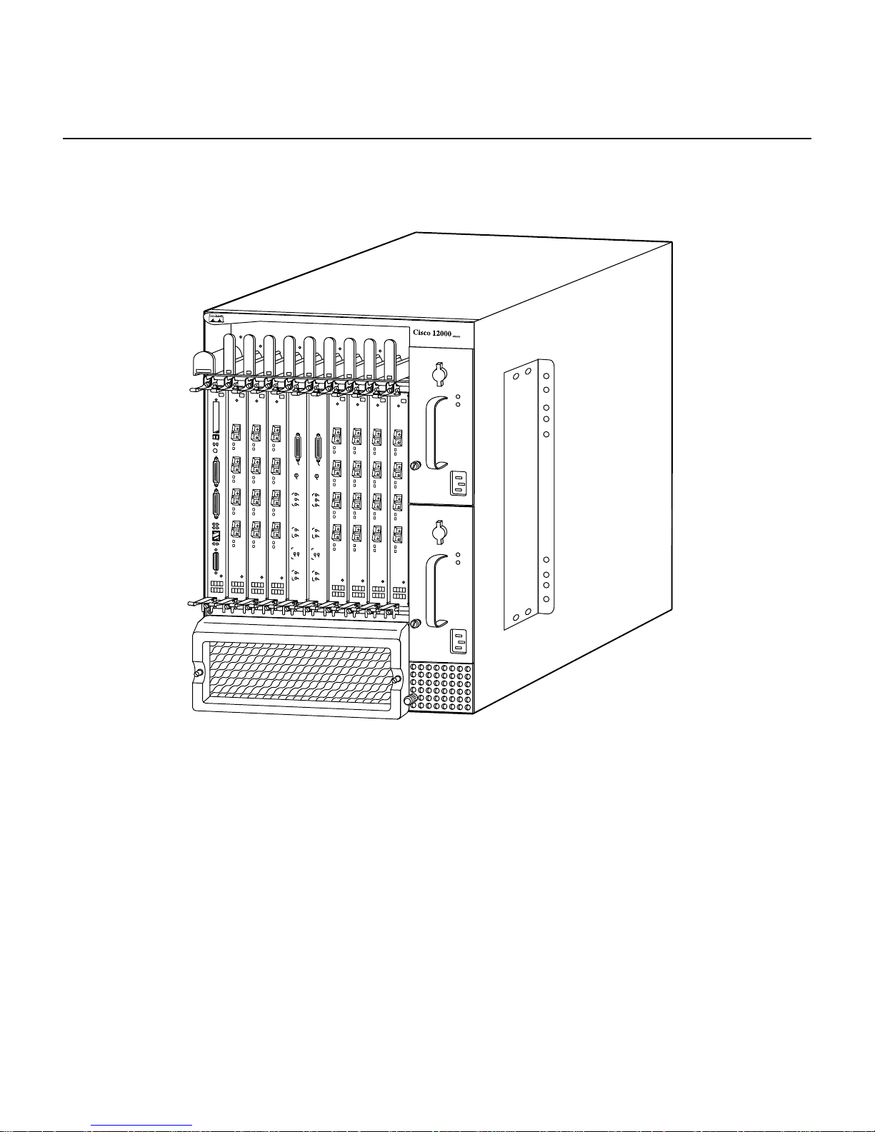
The Cisco 12008 rout er incorporat es a high-sp eed switchin g fabri c that pro vides high dat ahandling capacities for IP-based local- and wide-area networks . Figure 1-1 is a front vie w
of the Cisco 12008 router.
Features of the Cisco 12008 Router
All of the router’s major components and FRUs are accessible from the fron t of the router
enclosure, making the router easy to install, configure, and maintain.
Product Overview 1-3
Page 26
Features of the Cisco 12008 Router
Figure 1-1 Cisco 12008 Gigabit Switch Router
E
JE
C
T
S
S
L
L
O
O
T-0
T
-
1
R
E
A
S
U
E
T
X
C
O
N
S
O
L
E
L
IN
K
C
O
T
L
X
L
R
X
M
II
R
J
-4
5
GIGABIT ROUTE PROCESSOR
Alarm
ACO
/LT
Alarm
C
ritic
a
M
l
s
a
jo
r
M
in
o
r
C
C
S
F
S
a
C
il
E
n
a
b
le
d
F
F
a
a
n
n
F
F
a
a
il
il
P
LIN
W
R
E
S
C
AR
PL
Y
D
S
S
F
F
F
a
C
il
E
n
a
b
le
d
CSC-8
CSC-8
Alarm
ACO
/LT
Alarm
C
ritic
al
M
s
a
jo
r
M
in
o
r
F
ail
C
E
n
a
b
le
d
P
L
W
IN
R
EC
S
A
P
R
L
Y
D
F
a
C
il
E
n
a
ble
d
H7689
The Cisco 12008 supports the following features:
• Online insertion and removal (OIR) capability—This feature allows you to insert or
remove the following router components:
— Power supplies—One AC-input power supply or one DC-input power supply is a
required router component. You can remove or replace a power supply, without
disrupting system op erat ions , on ly if a seco nd (redundant) unit of the same t yp e i s
installed in the system.
1-4
Cisco 12008 Gigabit Switch Router Installation and Configuration Guide
Page 27

Features of the Cisco 12008 Router
The power supp lies of both types are hot-swappab le, load-sharing units. In a syst em
equipped with tw o AC-inpu t power suppl ies or two DC-input po wer supplies , if one
of the units fails or if the power source for one of the units fails, the surviving power
supply continues to operate to sustain normal router operations.
Note The Cisco 12008 does not support a mixture of AC-input and DC-input power
supplies.
— Cisco 12000 s eri es li ne cards —Any line card s up por t ed by the Cisco 12008 router
can be inserted into or removed from the router with no disruption to system
operations.
However, the functions performed by the removed card are lost to the system
temporarily until the card is either reinstalled or replaced by a like (and identically
configured) line card.
— Route Processor (RP)—As a required r outer component, an R P can be remov ed and
replaced, but you must power down the router before doing so.
An RP must be installed and operati onal at all times fo r normal sy st em oper a tio ns
to be sustained.
— Clock and scheduler card (CSC)—Also a required component, a CSC can be
removed and replaced, without disrupting normal system operations, only if a
second (redundant) CSC is installed in the system.
One CSC must be present and operational at all times to maintain normal system
operations.
— Switch fabric card (SFC)—An optional set of three SFCs can be installed in the
router at any time to provide additional switch fabric to the router. These cards
increase the data handling capacity of the router.
Any one or all of the SFCs can be remo ved and replaced at an y time without system
operations being disrupted or the router being powered down.
For the length of time that any SFC is not functional, its switch fabric is lost to the
router as a potential data path for the router’s dat a handling and swit ching functions.
Product Overview 1-5
Page 28

Overview of the Cisco 12008
Separately orderable d ocuments called config uration notes or replacement instructions
are available for each of the FRUs described previously. These documents provide
installation, removal, replacement, and configuration instructions for the FRUs.
• Enviro nmental monit oring system—The maintenance bus (MBus) facility of the Cisco
12008 functions as an environmental monitoring system for the router, enabling the
router to monitor itself and alert site personnel to adverse electrical events or
environmental conditions.
MBus software running in the RP, in combination with LEDs on the CSC faceplate,
keep site personnel informed regarding the operational state of the router.
By signaling alarm conditions, such as component overheating or out-of-tolerance
voltages, the router enables you to resolve adverse environmental conditions before
operational limits are exceeded, thus preventing the router from shutting down.
The MBus facility of the router is described in greater detail in the section entitled
“Cisco 12008 Environmental Monitoring Facility” on page 74.
• Downloadable software—This feature allows you to remotely load new operational
software into Flash memory on the RP without physically accessing the router. Thus,
you can quickly, easily, and reliably perform software upgrades at any time.
Overview of the Cisco 12008
The Cisco 12008 is a modular system consisting of the elements shown in Figure 1-2.
The following sections describe the major elements of the Cisco 12008 in greater detail.
1-6
Cisco 12008 Gigabit Switch Router Installation and Configuration Guide
Page 29
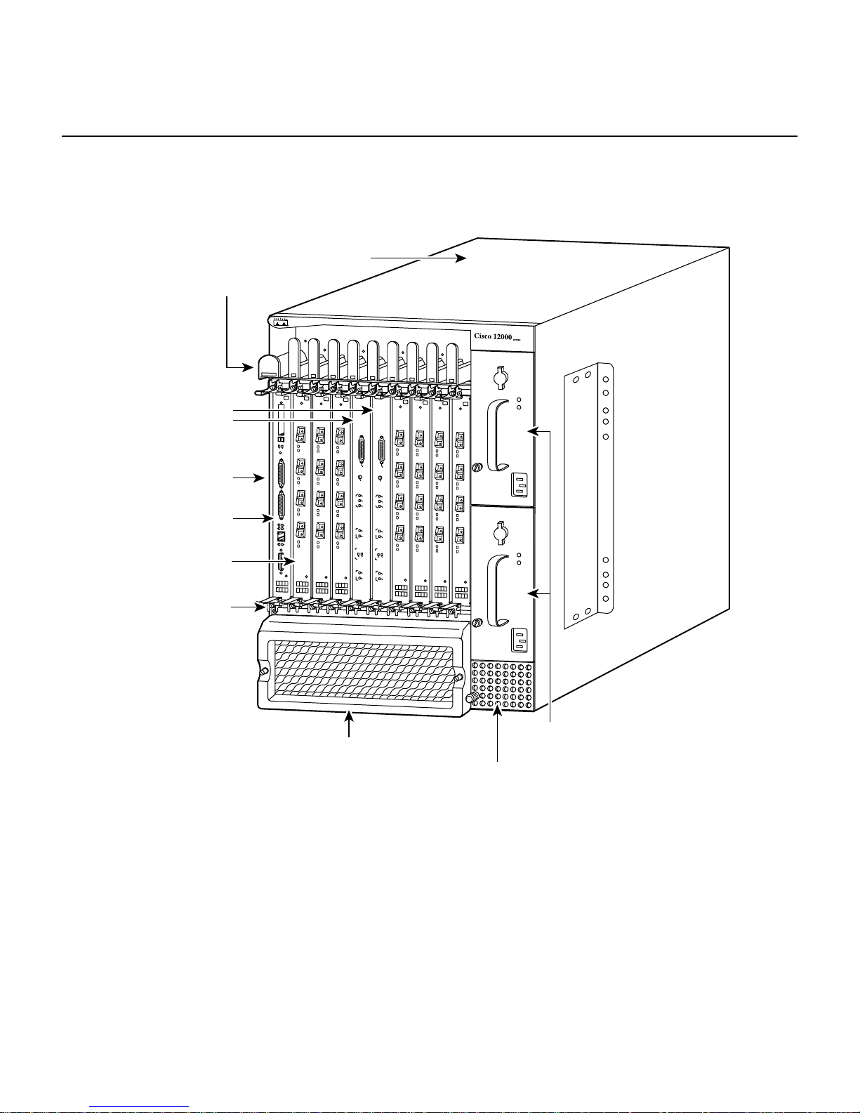
Figure 1-2 Major Components of the Cisco 12008
Router enclosure
Cable-management tray
CSCs
E
JE
C
T
S
S
L
L
O
O
T
T
-0
-1
R
E
S
A
E
U
T
Upper
card cage
RP
Line cards
(Quad OC-3
POS Shown)
ESD
connection
socket
X
C
O
N
S
O
L
E
L
IN
K
C
O
T
L
X
L
R
X
M
II
R
J-4
5
GIGABIT ROUTE PROCESSOR
Alarm
Alarm
AC
ACO/LT
O/LT
Alarms
Alarms
C
C
r
i
r
t
i
i
t
c
i
c
a
a
M
l
M
l
a
a
j
o
j
o
r
r
M
M
i
n
i
n
o
o
r
r
C
C
S
F
S
F
a
C
a
C
i
l
i
l
E
E
n
n
a
a
b
b
l
e
l
e
d
d
F
F
a
a
n
n
F
F
a
a
i
l
i
P
LIN
l
P
LIN
W
W
R
E
R
E
SP
C
S
C
A
A
R
PL
LY
R
D
Y
D
S
S
F
F
F
F
a
C
a
C
i
l
i
l
E
E
n
n
a
a
b
b
l
e
l
e
d
d
CSC-8
CSC-8
Overview of the Cisco 12008
H7691
(lower card cage behind air
filter assembly contains card
cage fan tray and SFCs)
Air filter assembly
AC- or DC-input power supplies
(AC-input power supplies shown)
Power supply
fan tray
Product Overview 1-7
Page 30

Overview of the Cisco 12008
Router Enclosure
The outer shell of the Cisco 12008 is a rigid, sheet metal structure with the following
dimensions:
• Width—17.4 inches (44.6 cm)
• Depth—21.2 inches (54.4 cm)
• Height— 24.8 inches (63.6 cm)
This enclosure, which houses all of the router’s internal components, can be mounted in a
telco rack or a four-post equipment rack, or the enclosur e can be used as a freestanding unit.
The design of the enclosure permits front accessibility of all router compo nents. All router
components plug into a backplane that provides operating power for the components and
interconnects them with each other.
The backplane, which is covered by a sheet metal panel that helps to completely enclose
the rear of the router, incorporates a nonv olatile random access memory (NVRAM) module
that stores the backplane serial number for identif ication and revision control pu rposes. The
contents of the NVRAM module are accessible from any line card slot.
Cable-Management System
The cable-management system provides an orderly and convenient way for you to manage
the network interface cables running to an d from the recei ve and transmit ports of installed
line cards.
Consisting of a cable-management tray and a vertical cable-management bracket (one
bracket for each installed line ca rd), the cable-management system (see Figure 1-3) secures
the network interface cables neatly in place. The cable management system helps to
optimize optical cable performance by eliminating any kinks or sharp bends in the cables.
Extreme curvatures in optical cables tend to degrade their performance.
The elements of the cable-management system are shown in Figure 1-3 and described
briefly in the following sections:
• Cable-management tray—This tray is attached to the router enclosure above the upper
card cage.
1-8
Cisco 12008 Gigabit Switch Router Installation and Configuration Guide
Page 31

Horizontal
cable-management
tray
Overview of the Cisco 12008
The cable management tray enables yo u to route the line card interf ace cables to or from
the system through the left s ide of the tray , keeping the cables o rganized, out of th e way ,
and free of kinks or sharp bends.
You direct the cables down to the individual ports on each line card, gauging cable
length appropriately to minimize slack in the cable before connecting it to a given port.
Figure 1-3 Cable-Management System
Captive screw
Vertical
cablemanagement
bracket
Captive screw
ESD socket
E
J
E
C
T
S
S
L
L
O
O
T
T
-0
-1
R
E
A
S
U
E
T
X
C
O
N
S
O
L
E
L
IN
K
C
O
T
L
X
L
R
X
M
II
R
J
-4
5
GIGABIT ROUTE PROCESSOR
Line card
Alarm
Alarm
ACO/LT
AC
O/LT
Alarms
Alarms
C
C
r
i
r
t
i
i
t
c
i
c
a
a
M
l
M
l
a
a
j
o
j
o
r
r
M
M
i
n
i
n
o
o
r
r
C
C
S
F
S
F
a
C
a
C
i
l
i
l
E
E
n
n
a
a
b
b
l
e
l
e
d
d
F
F
a
a
n
n
F
F
a
a
i
l
i
P
L
l
P
LIN
W
IN
W
R
EC
R
E
S
S
C
A
P
A
R
PL
LY
R
D
Y
D
S
S
F
F
F
F
a
C
a
C
i
l
i
l
E
E
n
n
a
a
b
b
l
e
l
e
d
d
CSC-8
CSC-8
H7705
Product Overview 1-9
Page 32

Overview of the Cisco 12008
• Vertical cable-management bracket (one per line card)—This bracket is attached to a
line card by means of captive installation screws at the top and bottom of the bracket.
Once an interface cable is connected to its intended line card port, you loop the cable
through the cable keeper clip nearest the port of connection and seat the cable in the
bottom of the bracket raceway.
Thus, the vertical cable-management bracket enables you to neatly “dress” all the
interface cables in place as you connect them to the individual line card ports.
Later, wh en you remov e or replace a line card, you need only discon nect the cables from
the individual line card ports (leaving the cables intact within the vertical cablemanagement bracket) and detach the bracket from the line card to be replaced.
When you install the new line card, y ou merely reattach the v ertical cable-management
bracket to the new line card and reconnect the interface cables to the appropriate line
card port(s).
Card Cage Fan Tray
The card cage fan tray is located in the lower card cage behind the air filter assembly (see
Figure 1-2). This fan tray maintains th e operat ing tem peratu r e of the router’s electronic
circuitry within an acceptable range.
Designed for simplicity, the card cage fan tray incorporates six fans mounted on a sheet
metal carrier . The assembly also contains associated wiring and a connector in the back of
the unit that enables it to draw operating power through the backplane from a DC-DC
converter on the CSC.
Guide rails in the sides of the lower card cage facilitate insertion and removal of the fan tray
assembly, which is secured in place by means of a captive installation screw on each side
of the metal carrier.
Under normal operating conditions, the v ariable-speed fans in the card cag e fan tray operate
at a reduced rate to
• Conserve power
• Reduce noise
• Minimize fan wear
1-10
Cisco 12008 Gigabit Switch Router Installation and Configuration Guide
Page 33

If an overtemperature condition or a fan failure is detected within the router, the master
MBus module on the RP di rects t he MB us mod ule on th e clo ck and sch e duler card (CSC)
to increase the operating voltag e being deli v ered to th e fan tray, causing the card cage fans
to run at “maximum” speed. This increases the volume of cooling air flowing through the
router.
If the increased fan speed does not alleviate the overtemperature condition in the affected
board, the MBus modu l e on the board shuts down the board’s power supply, taking the
board offline to protect it from thermal damage.
The MBus facility of the Cisco 12008 router is described in greater detail in the section
entitled “Cisco 12008 Environmental Monitoring Facility” on page 74.
Power Supply Fan Tray
The power supply fan tray is in the bottom of the power supply bays (see Figure 1-2). This
fan tray maintains the temperature of the installed power supply(ies) within an acceptable
range.
Overview of the Cisco 12008
Also designed for simplicity , the power supply fan tray incorporates four fans mounted on
a sheet metal carrier. The fan tray assembly contains associated wiring and a connector in
the back of the unit that enables it to draw operating power through the backplane from a
DC-DC converter on the CSC.
A captive installation screw mounted on the fan tray faceplate and guide rails in the sides
of the power supply bay facilitate insertion and removal of the unit. Once the unit is
inserted, you secure it in place by tightening the captive installation screw clockwise.
Similar to the card cage fan tray, the power supply fan tray is closely tied to the router’s
overall environmental monitoring system. If an overheating condition or a fan failure is
detected within the router, the v oltage being deliv ered to the power supply fans by the CSC
is also increased, thereby causing the power supply fans to run at “maximum speed” to
increase the volume of cooling passing through the power supply bays.
Product Overview 1-11
Page 34

Overview of the Cisco 12008
AC-Input and DC-Input Power Supplies
The Cisco 12008 router can be configured to operate with AC source power or DC source
power. Y o u can install one or two AC -i np ut p ower supplies or one or two D C -input powe r
supplies in the power supply bays located in the right side of the router enclosure (see
Figure 1-2).
A single power supply of either type is the standard router configuration. In such a
configuration, it is recommended that you install the power supply in the lower bay.
Y ou can i nstall a second (optional and redundant ) power supply of the same type for backup
purposes.
Caution A vacant power supply bay must be covered with a blank filler panel to ensure
proper flow of cooling air through the power supply bays and to satisfy EMI compliance
requirements.
Note You cannot use an AC-input power supply in conjunction with a DC-input power
supply . Ins talled po wer suppli es must alw ays be of th e same type. F urthermore, you s hould
not install two power supplies of either type unless you intend to actively use both units. In
other words, you should not power the router with a single power supply while using the
other bay to temporarily or indefinitely “store” an inert unit. Doing so will disrupt the
normal flow of cooling air through the router enclosure.
Figure 1-4 shows an AC-input power supply; Figure 1-5 shows a DC-input power supply.
1-12
Cisco 12008 Gigabit Switch Router Installation and Configuration Guide
Page 35

Figure 1-4 AC-Input Power Supply
0
INPUT
0K
OUTPUT
FAIL
Overview of the Cisco 12008
H10033
Product Overview 1-13
Page 36

Overview of the Cisco 12008
Figure 1-5 DC-Input Power Supply
THIS UNIT TO BE INSTALLED
IN A RESTRICTED ACCESS AREA
IN ACCORDANCE WITH THE NEC OR THE
AUTHORITY HAVING JURISDICTION
TER
MIN
ALS
MA
Y
BE
EN
ER
GIZ
Carrying handle
ED.
BER
UHR
EN
DER
ANS
CHL
USS
E
DEN
HAU
PTS
CHA
LTER
CAUTION
T
H
IS
U
N
IT
M
A
Y
H
A
V
E
M
O
R
E
T
H
A
N
O
N
E
P
O
W
C
O
N
T
O
D
0
E
R
S
U
P
P
L
Y
C
O
N
N
E
C
T
IO
N
.
A
L
L
N
E
C
T
IO
N
S
N
E
E
D
T
O
B
E
R
E
M
O
V
E
D
E
-E
N
E
R
G
IZ
E
T
H
E
U
N
IT
.
INPUT
0K
OUTPUT
FAIL
C
O
M
N
C
NO
H10032
Operating Modes of the Power Supplies
The AC-input and DC-input power supplies operate in either of two modes:
• Standalone mode—In this configuration, only one power supply is installed in one of
the two available power supply bays. To remove or replace a single power supply, you
must first power down the system.
1-14
Cisco 12008 Gigabit Switch Router Installation and Configuration Guide
Plastic safety shield
Page 37

• Redunda nt (1+1) m ode—In this configuration, two power supplies are installed in the
power supply bays, sharing the load current to provide required DC operating voltages
to the backplane. If one of the units fails, the surviving power supply takes over to
maintain normal system operations.
The online insertion and removal (OIR) capability of the router enables you to add or
remove a redundant power supply without introducing noise in the DC operating
voltages being supplied to the backplane.
Features of the Power Supplies
The AC-input and DC-input power supplies incorporate the following features:
• Onboard mainte nance b u s ( MBus) mo dule—The MB us module on the p owe r supply is
a microprocessor-based subassembly that links the power supply to the router’s
environmental monitoring system.
The environmental monitoring system includes identical MBus modules on all of the
router circuit boards, including the RP. This system enables you to perform router
functions and to respond to alarm conditions (such as overtemperature or overvoltage
conditions).
Overview of the Cisco 12008
An alarm condition in the router causes the MBus module on the CSC to illuminate an
appropriate LED on the card faceplate, providing a visible notification of the alarm
condition.
• Blind mating connector at the back of the unit —Supplies DC operating voltages to the
backplane for distribution to the router’s electronic and electrical components.
• OIR capability—Enables a second AC-in put power supply to be installed in or remo ved
from the router without disrupting normal system operations.
• Temperature sensor—Measures the ambient air temperature of the power supply.
Product Overview 1-15
Page 38

Overview of the Cisco 12008
Characteristics of the Power Supplies
The AC-input and the DC-input power supplies have the following characteristics:
• Width of power supply body—3.5 inches (8.97 cm)
• Width of power supply faceplate—4.0 inches (10.26 cm)
• Height—10 inches (25.64 cm)
• Depth—17.6 inches (45.13 cm)
• Weight (AC-input power supply)—17 lb (7.73 kg)
• Weight (DC-input power supply)—14 lb (6.36 kg)
• Power factor corrector (PFC)—Applicable only to the AC-input po wer supply , the PFC
enables the power supply to accept source AC voltages with the following
characteristics: voltages ranging from 180 to 264 VAC, single phase, 47 to 63 Hz.
AC-Input Power Supply Faceplate
This section describes the functional elements built into the faceplate of the AC-input
power supply (see Figure 1-6).
1-16
Cisco 12008 Gigabit Switch Router Installation and Configuration Guide
Page 39

Rotary power switch
Overview of the Cisco 12008
Figure 1-6 AC-Input Power Supply Faceplate
Carrying handle
tive installation screw
CAUTION
THIS UNIT MAY HAVE
MORE THAN ONE
POWER SUPPLY
CONNECTION. ALL
CONNECTIONS NEED
TO BE REMOVED TO
DE-ENERGIZE THE
UNIT.
ACHTUNG
DIESE EINHEIT HAT
MEHR ALS EINEN
NETZTEIL-ANSCHLUSS:
ALLE VERBINDUNGEN
MUSSEN ABGEZOGEN
WERDEN, DAMIT DIE
EINHEIT NICHT UNTER
SPANNUNG STEHT.
INPUT
200-240V
10 A
50/60 HZ
2000 W
AC INPUT
0K
OUTPUT
FAIL
~
LEDs
AC receptacle
with bail latch
H10031
Product Overview 1-17
Page 40

Overview of the Cisco 12008
Rotary Power Switch
The rotary power switch on the power supply faceplate (see Figure 1-6) applies a source
AC v oltage to the power supply. This switch also actuates an onboard circuit breaker and a
latching mechanism that prevents the power supply from being inserted into or removed
from the power supply bay when the switch is in the ON (1) position.
When you rotate the rotary power switch 90 degrees to the ON position, the following DC
operating voltages are supplied to the backplane:
• +5.2 VDC
• –48 VDC
Source AC Input Connector
The source AC receptacle on the power supply faceplate (see Figure 1-6) enables an
external A C po w er source to be connected to the power supply. This connector is equipped
with a latch that prevents accidental or unintended removal of the AC power cord.
The power specifications for the AC-input po wer supp lies, as well as the source AC po wer
cables available for use with the Cisco 12008 router, are described in Chapter 2 in the
section entitled “AC-Powered Systems.”
AC-Input Power Supply LEDs
The AC-inpu t po wer supply f aceplate incorporates two LEDs (see Figure 1-6) that prov ide
the following status indications:
• AC INPUT OK—When the rotary power s witch is turned ON, this green LED goes o n,
indicating that source AC power has been applied and that it is within the specified
operating range. If this LED does not go on when the rotary power switch is turned ON,
it indicates that source AC power is n ot within the specified operating range or that the
LED is faulty.
• OUTPUT FAIL—When the rotary power switch is turned on, this LED goes on
momentarily; it should then go off and remain so. If it does not go off, it indicates that
the +5.2 VDC or –48 VDC being supplied to the backplane is not within tolerance.
1-18
Cisco 12008 Gigabit Switch Router Installation and Configuration Guide
Page 41

DC-Input Power Supply Faceplate
This section describes the functional elements built into the faceplate of the DC-input
power supply (see Figure 1-7).
Overview of the Cisco 12008
Product Overview 1-19
Page 42

Overview of the Cisco 12008
Figure 1-7 DC-Input Power Supply Faceplate
Rotary power switch
Carrying handle
THIS UNIT TO BE INSTALLED
IN A RESTRICTED ACCESS AREA
IN ACCORDANCE WITH THE NEC OR THE
AUTHORITY HAVING JURISDICTION
CAUTION
TERMINALS MAY
BE ENERGIZED.
TURN OFF
POWER SOURCE
CIRCUIT
BREAKER AND
REMOVE POWER
SUPPLY BEFORE
ACCESSING
TERMINALS.
ACHTUNG
ANSCHLUSSE
KONNEN UNTER
SPANNUNG
STEHEN. VOR
DEM BERUHREN
DER
ANSCHLUSSE
DEN
HAUPTSCHALTER
ABSCHALTEN
UND DAS
NETZTEIL
ENTRERNEN
CAUTION
THIS UNIT MAY HAVE MORE THAN ONE
POWER SUPPLY CONNECTION. ALL
CONNECTIONS NEED TO BE REMOVED
TO DE-ENERGIZE THE UNIT.
INPUT
0K
OUTPUT
FAIL
COM
NC
NO
LEDs
Grounding posts
Ground sign
Standoff
Circuit breaker
alarm terminal block
Captive installation screw
Standoff
Knurled thumbscrew
1-20
Cisco 12008 Gigabit Switch Router Installation and Configuration Guide
CAUTION:
USE COPPER
CONDUCTORS ONLY
ATTENTION:
N'UTILISEZ QUE DES
CONDUCTEURS EN
CUIRVE
INPUT:
-48/-60V
39 A
1580 VA
Source DC lugs (2)
Source DC lugs (2)
H10030
Page 43

Overview of the Cisco 12008
Rotary Power Switch
The rotary power switch on the DC-input power supply performs the same functions as
those described in the section entitled “Rotary Power Switch” on page 18 for the AC-in put
power supply.
Circuit Breaker Alarm Terminal Block
The onboard power supply circuit breaker actuated by the rotary power switch on the DCinput power supply incorporates an auxiliary switch that is mechanically linked to (but
electrically isolated from) the power supply circuit breaker.
When the power supply circuit breaker is tripped by an overcurrent condition in the power
supply, this auxiliary switch mov es in unison, sending a signal to the circuit breaker alarm
terminal block on the power supply faceplate (see Figure 1-7).
To remotely sense when the power supply circuit breaker has been tripped during an
overcurrent condition, you can attach an external alarm-monitoring facility to the alarm
terminal block. When the power supply circuit breaker is tripped, power is no longer
delivered to the backplane an d the router ceases to operate. Hen ce, if you ha v e attached an
external alarm monitoring facility to the alarm terminal block, site personnel can be
instantly alerted to this serious fault condition.
T ypically , an e xternal alarm-monitoring system incorpor ates a light panel (visible alarm) or
a klaxon (audible alarm) as the means for alerting site personnel to an alarm condition.
To reset the alarm contacts on the alarm terminal block, you must turn the rotary power
switch on the power supply OFF and then ON again, much as you would reset any circuit
breaker.
Note Any time you manually actuate the rotary power switch, such as when powering
down the router, the contacts on the alarm terminal block remain unaffected. Hence,
activation of the contacts on the alarm terminal block occurs only during a power supply
overcurrent condition. In other words, these contacts are used to provide an immediate,
overt indication of a power supply fault condition; they are not used to merely indicate that
a circuit breaker has been turned off manually.
Product Overview 1-21
Page 44

Overview of the Cisco 12008
The three contacts on the alarm terminal block are labeled as follows:
• COM (Common)—This contact is common to both the Normally Open (NO) and the
Normally Closed (NC) contacts.
• NO (Normally Open)—These contacts on the alarm terminal block are open as long as
no overcurrent condition is detected in the power supply . When the power supply circuit
breaker is tripped during an overcurrent condition, these contacts are closed.
• NC (Normally Closed)—These contacts on the alarm terminal block are clos ed as long
as no overcurrent condition is detected in the power supply. When the power supply
circuit breaker is tripped during an overcurrent condition, these contacts are open.
Table 1-1 summarizes the status of the contacts on the alarm terminal block during an
overcurrent condition in the power supply.
Table 1-1 Circuit Breaker Status Indicated by the Alarm Terminal Block
Circuit Breaker Position NC Contact NO Contact
OFF (tripped) Open Closed
ON Closed Open
If you decide to use an external alarm-monitoring facility in conjunction with the alarm
terminal block, note that the contacts on the alarm terminal block ha v e a rating of 60 VDC
at 1A maximum.
Source DC Input Connectors
The faceplate of the DC-input power supply incorporates three sets of terminals for
connecting source DC power to the power supply (see Figure 1-7). From top to bottom,
these terminals are identified as follows:
• Ground
• + (positive)
• – (negativ e)
1-22
Cisco 12008 Gigabit Switch Router Installation and Configuration Guide
Page 45

Overview of the Cisco 12008
The power specifications for the DC-input power supplies, as well as the specifications of
the source DC power cables for us e with the Cisco 12008 router , are presented in the section
entitled “DC-Powered Systems” on page 16 in Chapter 2.
DC-Input Power Supply LEDs
The DC-input power supply faceplate incorporates tw o LEDs (see Figure 1-7) that provide
the following status indications:
• INPUT OK—When the rotary power switch is turned ON, this green LED goes on
immediately, indicating that source DC power is applied and that it is within the
specified operating range (–40.5 VDC to –75 VDC). If this LED does not go on when
the rotary power switch is turned ON, the source DC power being applied to the power
supply is not within the normal operating range or the LED is faulty.
• OUTPUT FAIL—When the rotary power switch is turned on, this LED goes on
momentarily; it should then go off and remain so. If it does not go off, it indicates that
the +5.2 VDC or –48 VDC being supplied to the backplane is not within tolerance.
Upper Card Cage and Associated Components
The upper card cage (see Figure 1-8) contains ten slots that accommodate the following
types of cards in the quantities indicated:
• One Route Processor (RP)—A RP is a standard and required router comp onent; the RP
must be present and operational at all times. It is recommended that you install the RP
in the left-most slot (slot 0) in the upper card cage.
• Either one or two clock and scheduler cards (CSCs)—One CSC is a standard and
required router component; one CSC must be present an d operational in the router at all
times. For redundancy, you can install a second CSC for use as a backup.
T wo dedicated s lots in the middle of the upper card cage (CSC0 and CSC1) are reserv ed
for the CSCs. Because the backplane connector of a CSC differs significantly from all
other card types, you cannot install a CSC in any other slot.
• Cisco 12000 series line cards—From one to seven line cards of different types can be
installed in the line car d slots in the up per cage (slots 0 throu gh 3 and slots 4 through 7).
Product Overview 1-23
Page 46

Overview of the Cisco 12008
Although you can install a line card in slot 0 , the recommended con v ention is for the R P
to occupy this slot.
Figure 1-8 Upper Card Cage of the Cisco 12008 Router
Upper
card
cage
E
J
E
C
T
S
S
L
L
O
O
T
T
-0
-1
R
E
A
S
U
E
T
X
C
O
N
S
O
L
E
L
IN
K
C
O
T
L
X
L
R
X
M
II
R
J
-4
5
GIGABIT ROUTE PROCESSOR
A
A
larm
larm
AC
ACO/LT
O/LT
Alarm
Alarm
C
C
r
i
r
t
i
i
t
c
i
c
a
a
M
l
s
M
l
s
a
a
j
o
j
o
r
r
M
M
i
n
i
n
o
o
r
r
C
C
S
F
S
F
a
C
a
C
i
l
i
l
E
E
n
n
a
a
b
b
l
e
l
e
d
d
F
F
a
a
n
n
F
F
a
a
i
l
i
P
L
l
P
L
W
IN
W
IN
R
E
R
E
S
C
S
C
A
PL
A
R
P
RD
Y
LY
D
S
S
F
F
F
F
a
C
a
C
i
l
i
l
E
E
n
n
a
a
b
b
l
e
l
e
d
d
CSC-8
CSC-8
H7690
A minimally configured Cisco 12008 contains the following cards in the upper card cage:
• One RP
• One CSC
• One Cisco 12000 series line card of any type
1-24
Cisco 12008 Gigabit Switch Router Installation and Configuration Guide
Page 47

A Cisco 12008 that is configured for full redundancy contains the following cards in the
upper card cage:
• Two RPs
• Two CSCs
• As many as six Cisco 12000 series line cards of any type and any combination
The following sections briefly descr ibe the cards that you can use to populate the upper card
cage.
Gigabit Route Processor
Each Cisco 12008 GSR has one main system (or route) processor . The route processor (RP)
processes the network routing protocols and distributes updates to the Cisco Express
Forwarding (CEF) tables on the line cards. The RP also performs general maintenance
functions, such as diagnostics, console support, and line card monitoring.
Overview of the Cisco 12008
Two types of RPs are available for the Cisco 12008 GSR:
• Gigabit Route Processor (GRP)
• Performance Route Processor (PRP)
When not explicitly specified, this document uses the term route processor (RP) to indicate
either the GRP or the PRP.
Note If you install a second, redundant RP, it must be of the same type as the primary RP.
This section describes the GRP and includes the following information:
• Memory components
• System status LEDs
• Soft reset switch
• Personal Computer Memory Card Industry Association (PCMCIA) slots, which are
used to transmit data to or from Flash memory cards
Product Overview 1-25
Page 48

Overview of the Cisco 12008
• Asynchronous serial ports
• Ethernet port
If you have a PRP, see the Performance Route Processor section.
The faceplate of the GRP is shown in Figure 1-9.
Figure 1-9 GRP Faceplate (Horizontal Orientation Shown)
It is recommended that you install the GRP in the left-most slot (slot 0 ) in the upper card
cage. Howev er, y ou need not abide by this recommendation. You can install the GRP in any
upper card cage slot, except for the two slots in the middle in the upper card cage (CSC0
and CSC1), which are reserved for the CSCs.
EJECT
COLL
SLOT-1
RESET
SLOT-0
AUX
CONSOLE
RX
TX
LINK
RJ-45
MII
GIGABIT ROUTE PROCESSOR
H10548
The GRP performs the following functions:
• Downloading the Cisco IOS software to all of the installed line cards at power up
• Providing a console (terminal) port for router configuration
• Providing an auxiliary port for other external equipment (such as modems)
• Providing an IEEE 802.3 , 10/100-me gabits-per -second (Mbp s) Ethernet port for Telnet
functionality
• Running routing protocols
• Building and distributing routing tables to line cards
• Providing general system maintenance function s
1-26
Cisco 12008 Gigabit Switch Router Installation and Configuration Guide
Page 49

Overview of the Cisco 12008
The GRP communicates with the line cards either through the switch fabric or through a
maintenance bus (MBus). The switch fabric connection is the main data path for routing
table distribution as well as for packets that are sent between the line cards and the GRP.
The MBus connection allows the GRP to download a system bootstrap image, collect or
load diagnostic information, and perform general, internal system maintenance operations.
The GRP plugs into any slot in the upper car d cage in the Cisco 12008 e xcept the rightmost
slot, which is reserved for the alarm card.
The GRP contains the following components:
• IDT R5000 Reduced Instruction Set Computing (RISC) processor used for the CPU.
The CPU runs at an external bus clock speed of 100 MHz and an internal clock speed
of 200 MHz.
• Up to 256 megabytes (MB) of parity-protected, extended data output (EDO) dynamic
random-access memory (DRAM) on two, 60-nanosecond (ns), dual in-line memory
modules (DIMMs); 64 MB of DRAM is the minimum shipping configuration.
• 512 kilobytes (KB) of static random-access memory (SRAM) for secondary CPU cache
memory functions (SRAM is not user configurable or field upgradeable).
• 512 KB of NVRAM (NVRAM is not user configurable or field upgradeable).
• Most of the additional memory components used by the system, including onboard
Flash memory (8-MB) and up to two PCMC IA-based Flash memor y cards. The def ault
GRP PCMCIA Flash memory is 20 megabytes (MB).
• Air-temperature sensors for environmental monitoring.
The Cisco IOS software im ages that run the Cis co 12008 reside i n Flash memory, which is
located on the GRP in the form of a single in-line memory module (SIMM), and on up to
two Personal Computer Memory Card International Association (PCMCIA) cards (called
Flash memory cards) that insert in the two PCMCIA slots (slot 0 and slot 1) on the front of
the GRP. (See Figure 1-9.) Storing the Cisco IOS images in Flash memory enables you to
download and boot from upgraded Cisco IOS images remotely or from software images
resident in GRP Flash memory.
Note EIA/TIA-232 was previously known as recommended standard RS-232 before its
acceptance as a standard by the Electronic Industries Association (EIA) and the
Telecommunications Industry Association (TIA).
Product Overview 1-27
Page 50

Overview of the Cisco 12008
The Cisco 12008 supports downloadable system software for most Cisco IOS software
upgrades, enabling you to remotely download, store, and boot from a new Cisco IOS
software image.
GRP Memory Components
Table 1-2 lists the memory components on the GRP. Figure 1-10 shows the location of the
two DRAM SIMMs and the Flash SIMM on the GRP.
Table 1-2 GRP Memory Components
Memory Type Memory Size Quantity Description
DRAM 641 to 256 MB
1 or 2 64- or 128-MB DIMMs (based on
DRAM required) for main Cisco IOS
software functions
SRAM 512 KB (fixed)
2
SRAM for secondary CPU cache
memory functions
NVRAM 512 KB (fixed)
3
MVRAM for the system configurati on
file
Flash memory
4
SIMM
Flash memory
(card)
8 MB 1 Contains Cisco IOS software images and
other user-defined files on the GRP
20 MB
5
1 or 2 Contains Cisco IOS software images and
other user-defined files on up to two
PCMCIA-based Flash memory cards
6
Flash boot ROM 512 KB 1 Flash EPROM for the ROM monitor
program bo ot im ag e
1. 64 MB of DRAM i s the default DRAM configuration for the G RP.
2. SRAM is not user configurable or field upgradeable.
3. NVRAM is not user configurable or field upgradeable.
4. The SIMM socket is wired according to Cisco’s own design and does not accept industry-standard 80-pin Flash
SIMMs.
5. 20-MB Flash m em ory card is the default shipping conf igu ration for the Cisco 12008.
6. A Type 1 or Typ e 2 PCMCIA card can be used in either PCMCIA slo t.
1-28
Cisco 12008 Gigabit Switch Router Installation and Configuration Guide
Page 51

Figure 1-10 Locations of GRP Memory
Backplane connector
Overview of the Cisco 12008
Bank 2
DRAM DIMMs
Bank 1
PCMCIA slots
slot 0: bottom
slot 1: top
U42
U39
U17
T
C
-1
T
T
E
E
J
O
S
E
L
E
S
R
-0
T
O
L
S
X
U
A
Auxiliary port
Console port
5
L
L
J-4
O
X
R
C
R
II
K
X
T
M
IN
L
Ethernet
interface
(RJ-45 or MII)
Flash
SIMM
H10547
GIGABIT ROUTE PROCESSOR
Alphanumeric
LED displays
Product Overview 1-29
Page 52

Overview of the Cisco 12008
DRAM
The extended data output (EDO) dynamic random-access memory (DRAM) on the GRP
stores routing tables, protocols, and network accounting applications, and runs the
Cisco IOS software. The standard (default) GRP DRAM configuration is 64 megabytes
(MB) of EDO DRAM, which you can increase up to 256 MB through DRAM upgrades.
The Cisco IOS software runs from within GRP DRAM.
T wo DRAM DIMM sock ets are incorporated into the GR P, as shown in Figure 1-10. These
sockets, labeled U39 (P4 DRAM bank 1) and U42 (P4 DRAM bank 2), enable you to
configure DRAM in increments ranging from 64 MB to 256 MB. Table 1-3 lists the
available upgrade configurations for DRAM on the GRP.
Table 1-3 DRAM Configurations
Total DRAM Product Numbers DRAM Sockets Number of DIMMs
64 MB
1
MEM-GRP/LC-64(=) U39 (bank 1) 1 64-MB DIMM
128 MB MEM-GRP/LC-64(=) U39 (b ank 1) and
U42 (bank 2)
128 MB MEM-GRP/LC- 128(=) U39 (bank 1) 1 128-MB DIMM
256 MB MEM-GRP/LC- 256(=) U39 (bank 1) and
U42 (bank 2)
1. 64 MB is the standa rd (default) DRAM confi gura t ion for the GRP.
Caution
To prevent memory problems, DRAM DIMMs must be 3.3 V, 60-nanosecond
2 64-MB DIMMs
2 128-MB DIMMs
(ns) devices. Do not attempt to install memory devices in the DIMM sockets that do not
meet these requirements.
SRAM
SRAM provides secondary CPU cache memory. The standard GRP configuration is
512 KB. Its principle function is to act as a staging area for routing tables update
information to and from the line cards. SRAM is not user conf igurable or f ield-upgradeable.
1-30
Cisco 12008 Gigabit Switch Router Installation and Configuration Guide
Page 53

Overview of the Cisco 12008
NVRAM
The system configuration, software configuration register settings, and environmental
monitoring logs are contained in the 512-KB NVRAM, which is backed up with built-in
lithium batteries that retain the contents for a minimum of five years. NVRAM is not user
configurable or field-upgradeable.
Caution Before you replace the GRP in the system, back up the runn ing conf iguration to
a Tri vial File Transfer Protocol (TFTP) f ile server or an installed Flash memor y card so you
can retrieve it later. If the configuration is not saved, the entire configuration will be lost—
inside the NVRAM on the removed GRP—and you will have to reenter the entire
configuration manually. This procedure is not necessary if you are temporarily removing a
GRP; lithium batteries retain the conf iguration in mem ory until you r eplace the GRP in the
system.
Flash Memory
Both the onboard and PCMCIA card-based Flash memory allo w you to remotely load and
store multiple Cisco IOS software and microcode images. You can download a ne w image
over the network or from a local server and then add the new image to Flash memory or
replace the existing files. You can then boot the routers either manually or automatically
from any of th e stored images. Flash memo ry also functions as a TFTP s erver to allo w other
servers to boot remotely from stored images or to copy them into their own Flash memory.
System Status LEDs
This section describes the two types of system status LEDs used on the GRP: the LED
indicators and the alphanumeric LED displays.
• The GRP has the following eight LED indicators:
— Two PCMCIA activity LEDs (one per PCMCIA slot): these LEDs light when the
slot is accessed. The LEDs receive power from the switched slot voltage.
— Four RJ-45 Ethernet por t LEDs: these LEDs are used in conjunction with the RJ-45
Ethernet connector. When the MII Ethernet port is in use, the LEDs are disabled.
The LEDs indicate link activity, collision detection, data transmission, and data
reception.
Product Overview 1-31
Page 54

Overview of the Cisco 12008
— Two RJ-45 or MII Ethernet port select LEDs: these LEDs, wh en on, identify which
one of the two Ethernet connections you selected. When the RJ-45 port is selected,
its LED is on and the MII LED is off. When the MII port is selected, its LED is on
and the RJ-45 LED is off.
• The alphanumeric displays are organized as two rows of four characters each. The
displays’ content is controlled by the MBus module software. The displays’ content is
controlled by the GRP’s MB us modu le softw are. Both ro w s of the disp lay are powered
by the MBus module.
These alphanumeric displays provide information about the following:
— System status messages that are displayed during the boot process
— System status messages that are displayed after the boot process is complete
During the boot process, the alphanumeric LED displays are controlled directly by the
MBus. After the boot process, they are controlled by the Cisco IOS software (via the
MBus), and display messages designated by the Cisco IOS software.
The following levels of system operation are displayed:
— Status of the GRP
— System error messages
— User-defined status/error messages
Note A complete, descriptive list of all system and error mes sages is located in the Cisco
IOS System Error Messages publications.
Soft Reset Switch
A soft reset switch is provided on the GRP faceplate to enable you to reset the software
running on the R5000 R ISC pro cess or of t he GRP. You access this switch through a small
aperture in the GRP faceplate. To activate the switch, you can press a ball-point pen or
similar pointed instrument into the opening.
1-32
Cisco 12008 Gigabit Switch Router Installation and Configuration Guide
Page 55

Overview of the Cisco 12008
Caution To prevent system problems or loss of data, use the sof t rese t switch only at the
advice of Cisco service personnel.
PCMCIA Slots
The GRP has two PCMCIA slots av ailable. Either s lot can support a Flash mem ory card or
an input/output (I/O) d evice as lon g as the device re quires only +5 VDC. The GRP s upports
T ype 1 and T ype 2 d evices; it does n ot support +3.3 VDC PCMCIA de vices. Each PCMCIA
slot has an ejector button for ejecting a PCMCIA card from the slot.
Asynchronous Serial P orts
Two asynchronous serial ports are provided on the GRP faceplate—a console port and an
auxiliary port. These ports enable you to connect external devices that you can use to
monitor and manage the system.
• Console port—The console port is an Electronics Industries Association/
Telecommunications Industry Association (EIA/TIA)-232 female receptacle that
provides a data circuit-termin ating equipment (DCE) interf ace for connecting a console
terminal.
• Auxiliary port—The auxiliary port is an EIA/TIA-232 male plug that provides a data
terminal equipment (DTE) interface. This auxiliary port supports flow control and is
often used to connect a modem, a channel service unit (CSU), or other optional
equipment for Telnet management.
Ethernet Port
The GRP has one Ethernet port that you can access using either of the follo wing connection
types:
• RJ-45 receptacle: an 8-pin, media dependent interface (MDI) that supports an IEEE
802.3 10BaseT (10 Mbps) or an IEEE 802.3u 100BaseTX (100 Mbps) Ethernet
connection.
• MII receptacle: a 40-pin, media independent interface (MII) that provides additional
flexibility for making Ethernet connections. The pinout of this standard 40-pin
receptacle is defined by the IEEE 802.3u standard.
Product Overview 1-33
Page 56

Overview of the Cisco 12008
Note The RJ-45 and MII receptacles on the GRP faceplate represent two physical
connection options for one Ethernet interface; therefore, you can use either the MDI RJ -45
connection or the MII connection, but not both simultaneously.
Performance Route Processor
Each Cisco 12012 GSR has one main system (or route) processor . The route processor (RP)
processes the network routing protocols and distributes updates to the Cisco Express
Forwarding (CEF) tables on the line cards. The RP also performs general maintenance
functions, such as diagnostics, console support, and line card monitoring.
Two types of RPs are available for the Cisco 12012 GSR:
• Gigabit Route Processor (GRP)
• Performance Route Processor (PRP)
When not explicitly specified, this document uses the term route processor (RP) to indicate
either the GRP or the PRP.
Note If you install a second, redundant RP, it must be of the same type as the primary RP.
The section describes the Performance Route Processor (PRP) and includes the following
information:
• PRP Memory Components
• System Status LEDs
• Soft Reset Switch
• PCMCIA Slots
• Asynchronous Serial Ports
• Ethernet Port
If you have a GRP, see the Gigabit Route Processor section.
1-34
Cisco 12008 Gigabit Switch Router Installation and Configuration Guide
Page 57

Overview of the Cisco 12008
Figure 1-11 shows the front panel view of the PRP.
Figure 1-11 Performance Route Processor (Front Panel View, Horizontal
Orientation Shown)
EJECT
ETH 1ETH 0 AUX
SLOT-1
SLOT-0
Y
R
A
M
I
R
P
RX
TX
EN
LINK
Y
R
A
IM
R
P
RX
TX
EN
LINK
CONSOLE
RESET
PERFORMANCE ROUTE PROCESSOR 1 (PRP-1)
The PRP is available as Product Number PRP-1=, which includes one PRP with 512 MB
of synchronous dynamic random-access memory (SDRAM) and one 64-MB advanced
technology attachment (ATA) Flash disk.
The primary functions of the PRP are as follows:
• Downloading the Cisco IOS software to all of the installed line cards at power up
• Providing a console (terminal) port for router configuration
• Providing an auxiliary port for other external equipment (such as modems)
• Providing two IEEE 802.3, 10/100-megabits-per-second (Mbps) Ethernet ports for
Telnet functionality
• Running routing protocols
• Building and distributing routing tables to line cards
• Providing general system maintenance function s
75041
• Communicating with line cards either through the switch fabric or through the
maintenance bus (MBus)
The MBus connection allows the PRP to do wnload a system bootstr ap image, collect or
load diagnostic information, and perform general, internal system maintenance
operations. The switch fabric connection is the main data path for routing table
distribution as well as for packets that are sent between line cards and the PRP.
The PRP contains the following components:
• Motorola PowerPC 7450 central processing unit (CPU). The CPU runs at an external
bus clock speed of 133 MHz and an internal clock speed of 667 MHz.
Product Overview 1-35
Page 58

Overview of the Cisco 12008
• Up to 2 GB of SDRAM on two PC133-compliant, dual in-line memory modules
(DIMMs). 512 MB of SDRAM is the default shipping configuration. SDRAM is field
replaceable.
• Two MB of SRAM for secondary CPU cache memory functions. SRAM is not user
configurable or field replaceable.
• Two MB of NVRAM. NVRAM is not user configurable or field replaceable.
• Additional memory components used by the system, includ ing onboard Flash memory
and up to two Flash memory cards.
• Air-temperature sensors for environmental monitoring.
The Cisco IOS software images th at run the C isco 12000 series Internet Router system are
stored in Flash memory. Two types of Flash memory ship wi th the PRP:
1 Onbo ard Flash memory — Ships as a si ngle in-line memory module (SIMM). This
Flash memory contains the Cisco IOS boot image (bootflash) and is not field
replaceable.
2 Flash disk— The PRP ships with a Flash disk that can be installed in either Flash disk
slot. (See Figure 1-12.) The Flash disk contains the Cisco IOS software image.
Storing the Cisco IOS images in Flash memory enables you to download and boot from
upgraded Cisco IOS software images remotely, or from software images that reside in PRP
Flash memory.
Cisco 12000 ser ies Internet Routers support do wnloadable system soft ware for m ost Cisco
IOS software upgrad es. This enables you to remotely downlo ad, store, and boot fro m a new
Cisco IOS software image. The Cisco IOS software runs from within the PRPs SDRAM.
Figure 1-12 shows the locations of the various hardware components on the PRP.
1-36
Cisco 12008 Gigabit Switch Router Installation and Configuration Guide
Page 59

Figure 1-12 PRP (Horizontal Orientation)
1
Overview of the Cisco 12008
3
2
T
C
E
J
E
SLOT-1
SLOT-0
Y
R
A
IM
R
P
EN
LINK
ETH 1ETH 0 AUX
RX
TX
EN
Y
R
A
IM
R
P
LINK
CONSOLE
RX
TX
R
E
S
E
T
PERFORMANCE ROUTE PROCESSOR 1 (PRP-1)
4
5 7 8 109
6
75042
Product Overview 1-37
Page 60

Overview of the Cisco 12008
1 Backplane connector 6 Ethernet ports
2 Flash SIMM (Socket number P3) 7 Auxiliary port
3 SDRAM DIMMs
Bank 1 - Socket number U15
Bank 2 - Socket number U18
4 Ejector lever 9 Handle
5 Flash disk slots (covered) 10 Display LEDs
PRP Memory Components
Table 1-4 lists the memory components on the PRP.
Table 1-4 PRP Memory Components
8 Console port
Type Size Quantity Description
SDRAM
SRAM
NVRAM
Flash
memory
1
2
512 MB, 1 GB, or
2 GB
1 or 2 512-MB and 1-G B DIMMs (based on de s i re d SD R A M
configuration) for main Cisco IOS software functions
2 MB (fixed) — S econdary CPU cache memory functions
3
2 MB (fixed) 1 System configuration files, register settings, and logs
4
64 MB SIMM
1 Cisco IOS boot image (bootflash), crash information, and other
user-defined files
Flash disks
5
1 or 2 Cisco IOS software images, system configuration files, and other
user-defined files on up to two Flas h disks
Flash boot
512 KB 1 Flash EPROM for the ROM monitor program boot image
ROM
1. Default SDRA M configuration is 512 MB. Ban k 1 (U 15) must be populated first. You ca n use one or both banks to
configure SDRAM combinations of 512 MB, 1 GB, or 2 G B. 1. 5-GB configurations are not supp ort ed.
2. SRAM is not user configurable or field replaceable.
3. NVRAM is not user configurable or field replaceable.
4. Flash memory SIMM is not user configurabl e or fi el d replaceable.
5. ATA Flash disks and Typ e I an d Ty pe II linear Flas h memory cards are supported. See the
“Flash Memory” for Flash disk information.
1-38
Cisco 12008 Gigabit Switch Router Installation and Configuration Guide
Page 61

Overview of the Cisco 12008
Note If a single DIMM module is installed, it must be placed in bank 1 (U15).
SDRAM
SDRAM stores routing tables, protocols, and network accounting applications, and runs the
Cisco IOS software. The default PRP conf iguration includes 512 MB of error checking and
correction (ECC) SDRAM. DIMM upgrades of 512 MB and 1 GB are available. You
cannot mix memory sizes. If tw o DIMMS are installed, they must be the same memory size.
Caution Cisco Systems strongly recommends that you use only Cisco -approved mem ory .
To prevent memory problems, SDRAM DIMMs must be +3.3VDC, PC133-compliant
devices. Do not attempt to install other devices in the DIMM sockets.
SRAM
SRAM provides 2 MB of parity-protected, secondary CPU cache memory. Its principal
function is to act as a staging area for routing tab le updates and for inf ormation sent to and
received from line cards. SRAM is not user configurable and cannot be upgraded in the
field.
NVRAM
NVRAM provides 2 MB of memory for system conf iguration f ile s, softw are conf iguratio n
register settings, and environmental monitoring logs. This information is backed up with
built-in lithium batteries that retain the contents for a minimum of 5 years. NVRAM is not
user configurable and cannot be upgraded in the field.
Flash Memory
Flash memory allows you to remotely load and store multiple Cisco IOS software and
microcode images. You can download a ne w image ov er the netw ork or from a local s erver
and then add the new image to Flash memor y or replace the existing files. You then can boot
the routers either manually or automatically from any of the stored images.
Product Overview 1-39
Page 62

Overview of the Cisco 12008
Flash memory also functions as a Trivial File Transfer Protocol (TFTP) server to allow
other servers to boot remotely from stored images or to copy them into their own Flash
memory . The onboard Flash memo ry (called bootflash) contains the Cisco IOS boot image,
and the Flash disk contains the Cisco IOS software image . A 64-MB ATA Flash disk s hips
by default with the PRP. Table 1-5 lists the supported Flash disk sizes and their Cisco
product numbers.
Table 1-5 Supported Flash Disk Sizes and Product Numbers
Flash Disk Size
64 MB
128 MB MEM-12KRP-FD128=
1 GB MEM-12KRP-FD1G=
1. Standard Type 1 and Type 2 linear Flash m em ory cards also are supported,
2. 64-MB ATA Flas h disk is the default shipping configuration.
2
although they may not have the capaci ty to meet the requirements of your
configuration.
1
Product Number
MEM-12KRP-FD64=
System Status LEDs
The sections describes the two types of system status LEDs used on the PRP: LED
indicators and alphanumeric LED displays.
The device or port activity indicators consist of the following functional groups:
• Two Flash disk activity LEDs (labeled SLOT-0 and SLOT-1)—1 LED per Flash disk
slot: these go on when the slot is accessed.
• Four RJ-45 Ethernet p ort LEDs (labeled LINK, EN, TX, and RX): used in con junction
with each of the RJ-45 Ethernet connectors. Each connector includes a set of 4 LEDs
that indicate link activity (LINK), port enabled (EN), data transmission (TX), and data
reception (RX).
• Two Ethernet connection LEDs (labeled PRIMARY): these two LEDs, when on,
identify which of the two Ethernet connections is selected. Since both ports are
supported on the PRP, the LED on port ETH0 is always on. The ETH1 LED goes on
when it is selected.
1-40
Cisco 12008 Gigabit Switch Router Installation and Configuration Guide
Page 63

Overview of the Cisco 12008
The alphanumeric display LEDs are o rg anized as two ro ws of four characters each and a re
located at one end of the card. These LEDs provide system status and error messages that
are displayed during and after the boot proces s. The boot process and the co ntent displayed
are controlled by the PRPs MBus module software.
At the end of the boot process, the LEDs are controlled by the Cisco IOS so ftware (via the
MBus), and the content displayed is designated by the Cisco IOS software.
The alphanumeric display LEDs provide information about the following:
• Status of the PRP
• System error messages
• User-defined status and error messages
Note A complete, descriptive list of all system and error mes sages is located in the Cisco
IOS System Error Messages publications.
Soft Reset Switch
The soft reset switch causes a nonmaskable interrupt (NMI) and places the PRP in ROM
monitor mode. When the PRP enters ROM monitor mode, its behavior depends on the
setting of the PRP software configuration register. (For more information on the software
configurat ion register , refer to the Con figuring the So ftware Conf iguration Re gister section
in Chapter 4) For ex ample, when the bo ot f ield of the so ftware con fig uration re gister is set
to 0x0, and you press the NMI switch, the PRP remains at the ROM monitor prompt
(
rommon>) and waits for a user command to boot the system manually. But if the boot field
is set to 0x1, the system automatically boots the first IOS image found in the onboard Flash
memory SIMM on the PRP.
Caution The soft reset (NMI) switch is not a mechanism for resetting the PRP and
reloading the IOS image. It is intended for software development use. To prevent system
problems or loss of data, use the soft reset switch only on the advice of Cisco service
personnel.
Product Overview 1-41
Page 64

Overview of the Cisco 12008
Access to the soft reset switch is through a small opening in the PRP faceplate. To press the
switch, you must insert a paper clip or similar small pointed object into the opening.
Flash Disk Slots
The PRP includes two Flash disk (PCMCIA) slots. Either slot can support an ATA Flash
disk or a Type 1 or Type 2 linear Flash memory card. The PRP ships by default with one
64-MB ATA Flash disk.
Note The PRP only supports +5VDC Flash disk devices. It does not support +3.3VDC
PCMCIA devices.
All combinations of different Flash devices are supported by the PRP. You can use ATA
Flash disks, Type 1 or Type 2 linear Fl ash memory cards, or a combination of the tw o. Each
Flash disk slot has an ejector button for ejecting a card from the slot.
Note T ype 1 and Type 2 linear Flash memory cards may not hav e the capacity to m eet the
requirements of your configuration.
Asynchronous Serial P orts
The PRP has two asynchronous serial ports, the console and auxiliary ports. These allow
you to connect external serial devices to monitor and manage the system. Both ports use
RJ-45 receptacles.
The console port provides a data circuit-terminating equipment (DCE) interface for
connecting a console terminal. The auxiliary port provides a data terminal equipment
(DTE) interface and supports flo w contr ol. It is often used to connect a modem, a chann el
service unit (CSU), or other optional equipment for Telnet management.
Ethernet Ports
The PRP includes two Ethernet ports , both using an 8-pin RJ-45 r eceptacle for either IE EE
802.3 10BASE-T (10 Mbps) or IEEE 802.3u 100BASE-TX (100 Mbps) connections.
1-42
Cisco 12008 Gigabit Switch Router Installation and Configuration Guide
Page 65

Note The transmission speed of the Ethernet ports is auto-sensing by default and is user
configurable.
Switch Fabric of the Cisco 12008
The heart of the Cisco 12008 is the switch fabric circuitry, which provides synchronized
gigabit speed interconnections between the line cards and the RP. The switch fabric
circuitry for the router is incorporated into two cards:
• Clock and scheduler card (CSC)—One CSC installed in the upper card cage is a
standard (required) router compon ent. The CSC represents one plane of switch fabric in
the router. This card is described in greater detail in the section entitled “Clock and
Scheduler Card.”
• Switch fabric card (SFC)—You can install a set of three optional SFCs in the lower card
cage to increase its switching (data-handling) capacity). Each SFC card represents one
plane of switch fabric in the router . This card is described in greater detail in the section
entitled “Switch Fabric Cards.”
Overview of the Cisco 12008
To achieve a fully redundant switch fabric with a switching capacity of 40 Gbps, you can
install two CSCs and three SFCs in the router; the second CSC provides redundancy of CSC
functions, as well as redundant switch fabric in the event of CSC or SFC failure.
Each CSC or SFC supports an OC-1 2 switc hing rat e for the rou ter (622 Mbps ). By addi ng
the set of three optional SFC cards, you can increase the switching capacity of the router to
an OC-48 rate (2.4 Gbps).
Table 1-6 lists the switch fabric bandwidth and the switch card configurations needed to
support an OC-12 switching rate or an OC-48 switching rate.
Product Overview 1-43
Page 66

Overview of the Cisco 12008
Table 1-6 Switch Fabric Configurations
Switch Fabric
Bandwidth
OC-12 nonre d undant 1
OC-12 redundant 2 0 2
OC-48 nonre d undant 1 3 4
OC-48 redundant 2 3 5
1. A CSC is a required router component.
Number of
CSCs
1
Number of
SFCs
01
Planes of Switch
Fabric
A minimally configured router (one with a single CSC and no SFCs) supports an OC-12
data rate, bu t provid es no redundan cy of CSC f unctions. Addi ng a second CS C to a system,
as well as the three optional SFCs, has the following effects:
• Increases the router’s bandwidt h from an OC-12 rate to an OC-48 rate.
• Increases the number of planes of switch fabric available to the router from one to five
(with the fifth serving as a redundant plane in the event of failure of a CSC or SFC.
• Provides full redundancy of CSC functions, such as the following:
— System clocking
— Resource allocation
— Scheduling
• Provides full redundancy in the router’s fan power and alarm functions.
Clock and Scheduler Card
The CSC is a multi-function circuit board that can be installed in one or both of two
reserved slots (CSC0 and CSC1) in the middle of the upper card cage (see Figure 1-2). The
standard router configuration requires one CSC in either slot CSC0 or slot CSC1. If you
configure your router with a single CSC, it is recommended that you install it in CSC1.
Each CSC is mounted on its own card carrier and incorporates an onboard power supply
that takes the –48 VDC supplied by the backplane and converts it into the 3.3 VDC
operating voltage required by the card’s electronics.
1-44
Cisco 12008 Gigabit Switch Router Installation and Configuration Guide
Page 67

Overview of the Cisco 12008
As a multi-function board, the CSC provides the following system serv ices:
• Provides one plane of switch fabric for the router (see the section below entitled “Switch
Fabric in the Cisco 12008”).
• Serves as a switch fabric controller card for the router (see the section below entitled
“Switch Fabric Controller Functions of the CSC”).
• Serves as an alarm monitoring facility for the router (see the section below entitled
“Housekeeping and Alarm Monitoring Functions of the CSC”).
• Provides onboard power for its own electronic circuitry, as well as power and control
functions for the fan trays (see the section below entitled “Board Power and Fan Tray
Power Functions of the CSC”).
These functions are described in the following sections.
Switch Fabric in the Cisco 12008
A switch plane in the router consists of one OC-12-rate crossbar in the backplane that
enables each line card slot in the router to be connected logically to every other line card
slot. Line cards installed in any combination of slots in the upper card cage can
communicate with each other by means of the router’s switch fabric.
The switch fabric of the router constitutes the totality of the possible data paths that can be
established through the router. The magnitude of the router’s switch fabric (and, hence, its
data- carrying capacity) is related directly to the number of switch planes that are made
available to the router for data-handling purposes. By installing a second CSC and/or the
optional set of three SFCs in the router, you can increase the number of switch planes
present in the router , the reby increasing the magnitude of the router’s ov erall swi tch fa bric.
Table 1-7 outlines the p os sibl e con figurations of CS Cs and SFCs and the r out er s witching
capacity that results from these configurations.
Product Overview 1-45
Page 68

Overview of the Cisco 12008
Table 1-7 Switch Planes Provided by Switch Cards
Switch Card Type Availability
One CSC Standard 1 A single CSC supports an OC-12 data rate
Second CSC Optional 1 A second CSC supports an OC-12 data
Three SFCs Optional 3 The optional set of three SFCs enables the
Number
of Switch
Planes Description
for the router, but provides no redundancy
in the router’s switch fabric.
rate for the router and also provides a
redundant plane of switch fabric. If one of
the CSCs fails, a fault recovery cuto ver to
the surviving CSC occurs, not only to
maintain the router’s OC-12 data rate, but
also to preserve the system services
peculiar to the CSC.
router to support an OC-48 data rate. In an
OC-48 rate
1
in the switch fabric. However, if a switch
plane failure occurs in a fully-redundant
system, a CSC can take over the functions
of either a failed CSC or a failed SFC, not
only to maintain the router’s OC-48 data
rate, but also to pr eserv e the essential CS C
system services.
system, no redundancy exists
2
1. Router eq uipped with one CSC and three SFCs.
2. Router eq ui pped with two CSCs and three SFCs.
Switch Fabric Controller Functions of the CSC
In addition to providing one plane of switch fabric for the router, the CSC provides
numerous other functions and services essential to router operations. Figure 1-13 illustrates
the primary functional elements of the CSC.
1-46
Cisco 12008 Gigabit Switch Router Installation and Configuration Guide
Page 69

Figure 1-13 Block Diagram of the CSC
Clock and scheduler card (CSC)
Overview of the Cisco 12008
Alarm
functions
Board
power
Master clock/
frame synch
generator
Central
switch
allocator
Single
plane
switch
fabric
Mbus
module
power
Fan
Request/grant
Switch data
Fabric control
Fan
trays
1
Line cards
and RP
cards
Clock
SFC
cards
CSC
card
(redundant)
2
0
1
7
0
1
2
H11724
The major functions of each element of the CSC are summarized briefly in the following
paragraphs.
• Master clock generator—This function on the CSC provides a clock source to the RP,
all installed switch cards (including the SFCs and a redundant CSC), and all installed
line cards. The master clock generator synchronizes the transfer of data through the
router’s switch fabric.
Product Overview 1-47
Page 70

Overview of the Cisco 12008
In a redundant CSC configuration, the phase of the master clock generator on one card
is synchronized with that of the other card. If either clock drifts, the master clock
generators on both cards remain tightly aligned.
Should one of the CSCs fail, the phase lock between the two master clock sources is
aborted within nanoseconds, enabling the surviving CSC clock to remain stable and take
over master clock duties.
• Frame synchronization generat or—This function o n the CSC pr ovides a periodic si gnal
to the line cards and switch cards to control data flow.
In a redundant CSC configuration, either CSC can adopt the frame synchronization
phase of the other to ensure ph ase a lignment. The line cards can switch between fr ame
synchronization masters without disruption.
If the frame synchronization function on one CSC f ails, cutover to the survi ving frame
synchronization generator on the other card occurs within nanoseconds, sustaining
system operations.
• Central switch allocator and scheduler—This function on the CSC allocates switching
resources to line cards and schedules (arbitrates) the flow of data through the router’s
switch fabric.
Switch arbitration begins with a set of requests from line cards to send data through the
router’s switch fabric. The scheduler plans a set of paths through the switch fabric to
carry as much data as possible per unit of time. At the next available time unit, the
request to send data is granted, and the data is sent to its dest ination. Th e next round of
switch arbitration (scheduling) then begins.
The scheduler also sends switch fabric control information to each switch plane to
create appropriate data paths through the switch fabric. When the new data paths are
configured into the switch fabric, data begins to flow toward the destination line card(s).
The central switch allocator and scheduler accepts data transport requests f rom all line
cards (including the RP), generates grants (accepted data transport reques ts), and driv es
all planes of the router’s switch fabric.
• Single plane switch fabric—The CSC’s single-plane switch fabric provides an OC-12
rate of switching capacity for the router. This switch fabric plane operates under control
of the CSC’s central switch allocator and scheduler.
1-48
Cisco 12008 Gigabit Switch Router Installation and Configuration Guide
Page 71

Overview of the Cisco 12008
This single switch plane of the CSC can be used alone in a minimum router
configuration, or it can be used in combination with another CSC and the three optional
SFCs for full switching redundancy. In the latter case, the per line-card slot bandwidth
of the router is increased from an OC-12 rate to an OC-48 rate, and the second CSC
provides redu ndan cy.
If any one switch plane fails in a fully redundant switch fabric, the failed plane is shut
down, and the router’s full data bandwidth is carried by the surviving planes. The fault
recovery cutover to another viable switch plane typically occurs without loss of data,
because the data path defect is detected while redundancy information is still available,
thus enabling error packets to be repaired “on the fly.”
Housekeeping and Alarm Monitoring Functions of the CSC
The section describes the following housekeeping and alarm monitoring facilities built into
the CSC:
• MBus module— The MBus mod ule on the CSC is a microproces sor-based su bassembly
that provides housekeeping services required during router power up and initialization.
It also supports the alarm monitoring LEDs on the CSC faceplate, as described in the
following section.
The MBus module on the CSC operates partly autonomously and partly under the
control of the master MBus module on the RP.
A failed MBus module on the CSC is detected by an MBus polling algorithm running
in the background on the RP.
A failed MBus module detected by this polling algorithm in a redundant CSC
configuration causes the master MBus module to execute an administrative cutover to
the MBus module on the surviving CSC. This cutover is accomplished with no
disrupti on of normal system operations.
• Alarm monitoring and status functions—The CSC supports the router’s alarm and status
monitoring functions. These functions are described in the following paragraphs.
Figure 1-14 shows the location of the alarm contact connector a nd the v arious LEDs on
the CSC faceplate through which the system accomplishes its alarm monitoring and
status reporting functions.
Product Overview 1-49
Page 72

Overview of the Cisco 12008
Figure 1-14 CSC Alarm Monitoring Facilities
Alarm
DB-25 alarm contact connector
A
larm
s
CSC
Fan
Fail
LINECARD
SFC
CSC-8
ACO/LT
Critical
Major
Minor
Fail
Enabled
PWR SPLY
Fail
Enabled
Alarm cutoff/lamp test button
System alarm LEDs
Status LEDs for the CSC
Status LEDs for each fan tray
Status LEDs for SFCs
H7701
1-50
Cisco 12008 Gigabit Switch Router Installation and Configuration Guide
Page 73

Overview of the Cisco 12008
— DB-25 alarm contact connector—A female DB-25 D-sub connector incorporated
into the CSC faceplate enables you to attach an external alarm monitoring facility
to the router, thus supporting a telco style of handling alarm conditions in the router .
The alarm signals sent to this DB-25 connector are identical in function to those
sent to the system LEDs on the CSC faceplate (see the following section entitled
“System Alarm LEDS”).
Any alarm condition in the router that activates one of the system alarm LEDs on
the CSC faceplate also energizes an appropriate CSC relay , causing a corresponding
signal to be sent to the DB-25 connector. If an e xternal alarm monitoring facility is
attached to the DB-25 connector, this signal activates the appropriate external
audible or visible alarm.
An external audible alarm can be reset by clearing the condition that caused the
alarm or by pressi ng the alarm cutoff reset/lamp tes t (ACO/LT) button on the CSC
faceplate (see the following discussion abo ut the AC O/LT button). A visual alarm,
however, can be reset only by resolving the problem that caused the alarm
condition.
Only safety extra-low voltage (SELV) external alarm circuits can be connected to
the DB-25 connector .
— One external closure sense line, enabling the router to monitor an external event,
such as the opening of a cabinet door or the activation of an alarm in associated
equipment.
— Alarm cutoff reset/lamp test (ACO/LT) button—If you equip your system with an
external alarm monitoring facility, a visible indication can be provided, and/or an
audible alarm can be sounded, to immediately notify site personnel of an alarm
condition in the router.
An audible alarm generated by the system continues to sound until you either clear
the alarm condition itself or press the A C O/LT button to silence the alarm. Merely
pressing this button does not resolve the alarm condition.
You can test the operability of the LEDs on the CSC(s), the SFC(s), and the power
supply(ies), by pressing the AC O/L T b utton at any time. Doing so causes the LEDs
on all these router components to remain lit as long as you hold down the button.
However, the LEDs on the SFCs are visible only when the air filter assembly is
removed.
Product Overview 1-51
Page 74

Overview of the Cisco 12008
In a system equipped with two CSCs, pressing the ACO/LT button on one CSC is
equivalent to pressing this button on either CSC or both CSCs.
— System alarm LEDs—Three system LEDs, labeled critical, major, and minor, are
incorporated into the CSC faceplate (see Figure 1-14) to signal the existence of
alarm conditions detected in the router by the system’s environmental monitoring
circuitry.
During an alarm condition, one o f these LEDs goes on to indicate the s everity of the
detected fault. During a critical alarm, the top LED ( Critical) on the CSC f aceplate
indicates red; similarly, during a major alarm , the middle LED (Major) on the CSC
faceplate also indicates red, signifying an alarm condition of lesser severity; finally ,
during a minor system alarm, the bottom LED (Mino r) indicates amber, signifying
an alarm condition of least severity.
At the same time that one of these LEDs goes on to signal the alarm event, an
associated alarm relay on the CSC is closed, se nding a co rres pon ding signal to the
DB-25 alarm contact connector on the CSC faceplate.
An alarm condition detected in a redundant CSC configuration causes the
appropriate relays on both CSCs to close, activating the visible and audible alarm
functions of the DB-25 connector on each card.
When the fault condition is resolved, MBus software running in the GRP
automatically clears the fault indication by communicating with the master MBus
module, which, in turn, communicates with the MBus module on each circuit
board.
— CSC Status LEDs—T wo LEDs on the CSC faceplate, the top one labe led F AIL and
the bottom one labeled ENABLED, indicate the operational status of the CSC.
— FAN FAIL Status LEDs for each fan tray—Two side-by-side LEDs on the CSC
faceplate indicate the operational status of the fan trays.
The LINECARD LED on the left pertains to the card cage fan tray, and the PWR
SPLY LED on the right pertains to the power supply fan tray.
— SFC Status LEDs—Two LEDs at the bottom of the CSC faceplate, the top one
labeled FAIL and the bottom one labeled ENABLED, indicate the operational
status of the SFCs in the lower card cage (behind the air filter assembly).
1-52
Cisco 12008 Gigabit Switch Router Installation and Configuration Guide
Page 75

If the FAIL LED goes on, it indicates that one of the three SFCs in the lower card
cage has failed. To determine which of the SFCs has failed, you must remove the
air filter assembly and examine the status of the LEDs on each SFC.
Two side-by-side LEDS behind a vertical tab near the center of the SFC (see
Figure 1-15) indicate the operational status of the card.
Figure 1-15 Status LEDs on an SFC
Overview of the Cisco 12008
Left LED
(OK)
Status LEDs
Right LED
(FAIL)
H11366
Board P ower and Fan Tray Power Functions of the CSC
DC-DC conv erters on the CSC provide po wer for its own circuitry, as well as power for the
fan trays. These functions are described briefly in the following sections.
• Board power —A DC-DC con verter on the CSC takes the –48 VDC being delivered to
the card from the backplane and converts it into the +3.3 VDC required to drive the
card’s electronic circuity.
No redundancy is built into the CSC for the +3.3 VDC operating voltage; if the DC-DC
conv erter fails to deliver this voltage, the card shuts down, at which time the redundant
CSC, if installed, takes over to maintain normal system operations.
Howev er , in a nonredundant CSC configuration, the failure of the installed CSC causes
the entire system to shut down.
Product Overview 1-53
Page 76

Overview of the Cisco 12008
• Fan tray power—The Cisco 12008 router contains two fan trays (see Figure 1-2).
Control of fan power is initiated at system startup, with the fans running at a slow rate
for normal operations. Such operation minimizes fan noise, wear, and power
consump tion. A DC-DC converter on the C S C provides +20 VDC for sl ow fa n
operation and +25 VDC for fast fan operation when an overtemperature condition is
sensed in the router.
Periodically, the master MBus module on the GRP polls the MBus module on each
circuit board to determine whether router components are cool enough to warrant
keeping the fans r unning at their minimum rate. If they are not, th e master MBus module
directs the MBus module on the CSC to increase the operating voltage being delivered
to the fan trays, causing the fans to run faster, thus increasing the volume of air being
circulated through the router.
Each fan is monitored separately for failure. A failed fan is not “shut off” in the usual
sense; rather, a current-limiting feature in the faulty fan prevents it from interfering with
the operation of other fans.
On failure of a fan in either the card cage f an tray or the po wer supply fan tray, the CSC
increases the voltage being delivered to the surviving fans, causing them to run faster to
compensate for the failed fan.
Cisco 12000 Series Line Cards
The Cisco 12008 comes equipped with the number and type of line cards that you or dered
already installed. Up to se ven Cis co 12000 series line cards can be inst alled in the router to
support a variety of physical network media.
The line cards can be installed in upper card cage slots 0 through 3 and slots 4 through 7.
Note, however, that it is recommended that the GRP be installed in slot 0. Line cards
interface to each other and the GRP through the router’s switch fabric.
The following types of line cards are available for use with the Cisco 12008:
• Quad OC-3c/STM-1c POS—4 ports
• OC-12c/STM-4c POS—1 port
• OC-12c/STM-4c ATM—1 port
1-54
Cisco 12008 Gigabit Switch Router Installation and Configuration Guide
Page 77

Overview of the Cisco 12008
These cards provide the interfaces to the router’s external physical media. They exchange
packet data with each other by way of the router’s switch fabric.
Caution Any unoccupied slot in the upper card cage must have a blank filler panel
installed for EMI compliance and to ensure proper air flow through the router enclosure.
A vertical cable-management bracket attached to the f aceplate of each line card enables you
to neatly arrange the network interface cables for connection to the individual ports on the
line card. The cable-management system is described in detail in the section entitled
“Cable-Management System” on page 8.
The online insertion and removal (OIR) capability of the Cisco 12008 enables you to
remove and replace a line card while the system remains powered up and operational.
The Cisco 12000 series line cards available for use with the Cisco 12008 router are
described briefly in the following sections.
Quad OC-3c/STM-1c POS Line Card
The Quad OC-3c/STM-1c POS line card provides the Cisco 12008 router with four
independent Packet-Over-SONET (POS) ports on a single card. The card interfaces with
the router’s switch fabric and provides four OC-3c/STM-1c SC-duplex SONET
connections. These connections are concaten ated, which provides for increased efficiency
by eliminating the need to partition the bandwidth.
Figure 1-16 shows a high-level bloc k diagram of the Quad OC-3c/STM-1 c POS line car d;
Figure 1-17 shows a front view of the card.
Product Overview 1-55
Page 78

Overview of the Cisco 12008
Figure 1-16 Block Diagram of the Quad OC-3c/STM-1c POS Line Card
Input
interfaces
Output
interfaces
Packet
receive
(Rx)
Forwarding
processor
Packet
transmit
(Tx)
Reassembly
Segmen-
tation
Burst
buffer
L3 switching
accelerator
Burst
buffer
Buffer
memory
queuing
queuing
Buffer
memory
Silicon
agent
Silicon
agent
MBus
module
Switch
interface
fabric
MBus
interface
Switch
fabric
H11726
1-56
Cisco 12008 Gigabit Switch Router Installation and Configuration Guide
Page 79

Figure 1-17 Quad OC-3c/STM-1c POS Line Card
Overview of the Cisco 12008
Single Mode
0
ACTIVE
CARRIER
RX PKT
1
ACTIVE
CARRIER
RX PKT
2
ACTIVE
CARRIER
RX PKT
Ejector lever
Port 0
Status LEDs
Port 1
Port 2
Multimode
0
ACTIVE
CARRIER
RX PKT
1
ACTIVE
CARRIER
RX PKT
2
ACTIVE
CARRIER
RX PKT
3
ACTIVE
CARRIER
RX PKT
Q OC-3/STM-1 SM IR POS
Port 3
3
ACTIVE
CARRIER
RX PKT
Q OC-3/STM-1 MM POS
Alphanumeric
LED display
Ejector lever
Front view Rear view
160-pin
backplane
signal
connector
H10781
Product Overview 1-57
Page 80

Overview of the Cisco 12008
Each Quad OC-3c/STM-1c POS line card incorporates the following major components:
• Transceivers—The single-mode intermediate reach transceiver provides a full-duplex,
155-Mbps, 1300-nm, laser-based SONET/SDH-compliant interface. The multimode
transceiver provides a full-duplex, 155-Mbps, 1300-nm, LED-based SONET/SDH
compliant interface.
The SONET specification for fiber-optic transmission defines two types of fiber: single
mode and multimode. Signals can travel farther through single mode fiber than through
multimode fiber.
The maximum distance for single-mode installations is determined by the amount of
light loss in the fiber path. Good quality single-mode fiber with very few splices can
carry an OC-3c/STM-1c signal 9.3 miles (15 km) or more; good quality miltimode fiber
can carry a signal up to 1.3 miles (2 km).
• Burst bu ffer s—The Quad-OC3c/STM-1c contains four 12 8-KB burst buf fers. The bu rst
buffer p rev ents the dropping of pack ets during instantaneous increases in the nu mber of
back-to-back small packets being transmitted at OC-3 line rates.
Burst buffers are used to achieve high throughput while smoothing out the arriving
packet burst for the Layer 3 switch processor.
• Buffer memory—The silicon queuing engine controls the placement of IP packets in
buffer memor y as well as their removal from buffer memor y. The default packet buffer
memory is 32 MB, which includes 16 MB of receiv e (Rx) buffers and 16 MB of transmit
(Tx) buffers.
The buffer memory can be conf igured to suppor t up to 64 MB of receiv e bu ffer s and up
to 64-MB of transmit buf fers. The b uf fers can suppor t delays comparable to th e longest
round trip delays measured in the Internet at OC-3c/STM-1c line rates.
• Layer 2 switching accelerator—The Layer 2 switching accelerator assists the
forwarding processor. It is a specially designed application-specific integrated circuit
(ASIC) that optimizes access to the Layer 2 and Layer 3 information within each pack et.
At very high line rates, this access process must be executed as rapidly as possible,
which is why an ASIC is dedicated to the process.
• Forwarding pro cess or —A forwarding processor makes forwarding decisions based on
the information in the Ci sco Express Fo rwarding (CEF) table and the Layer 2 and Layer
3 information in the packet. The GRP con stantly updates forward ing information in the
forwarding table based on the latest information in the routing table.
1-58
Cisco 12008 Gigabit Switch Router Installation and Configuration Guide
Page 81

Overview of the Cisco 12008
Once the forwarding decision has been made, the silicon queuing engine is notified by
the forwarding processor , and the silicon q ueuing engine places the packet in the proper
queue.
This partitioning between the Layer 2 switching accelerator and the forwarding
processor blends the high throughput of hardware-accelerated forwarding with the
flexibility of software-based routing.
• Silicon queuing engine—Each line card has two silicon queuing engines: receive and
transmit. The receive engine moves packets from the burst buffer to the switch fabric,
and the transmit engine moves packets from th e switch f abr ic to the transmit interface.
When an incoming IP packet is clocked into the silicon queuing engine, the packet’s
integrity is verified by a check of the CRC. Next, the silicon queuing engine transfers
the IP packet to buffer memory and tells the Layer 3 switching accelerator the location
of the IP packet.
Simultaneously, the silicon queuing engine is receiving forwarding information from
the forwarding proces sor . T he forw arding pr ocessor tells the s ilicon queuing engine the
virtual output queue where the IP packet is to be placed.
Each virtual output queue represents an output destination (d estination line card ). Th is
placement of the IP packets in a virtual output queue is based on the decision made by
the forwarding processor. There is one virtual output queue for each line card, plus a
dedicated virtual output queue for multicast service.
The transmit silicon queuing engine moves the packet from the switch fabric to the
transmit buffer, and then to the transmit interface.
• Switch fabric interface—The switch f abric interf ace is the same 1.25-Gbps, full-du plex
data path to the switching fabric that is used by the GRP . Once a packet is in the proper
queue, the switch fabric interface issues a request to the master clock scheduler on the
CSC. The scheduler issues a grant and transfers the packet across the switching fabric.
• Maintenance bus (MBus ) module—A maintenance bus (MBus) mo dule on the line card
responds to requests from t he master MBus modu le on the GRP. The MBus module on
the line card reports temperature and voltage information to the master MBus module.
In addition, the MBus module on the line card contains the ID-EEPROM, which stores
the serial number, hardware revision level, and other information about the card.
Product Overview 1-59
Page 82

Overview of the Cisco 12008
• Cisco Express F orwarding (CEF ) memory table—Each line card maintains CEF tables.
These tables, derived from routing tables maintained by the GRP, are used by the line
card processor in making forwarding decisions.
Large networ ks may require mo re DRAM to support lar ge CEF tables . For in formation
on adding memory to a line card, see the document entitled Cisco 12000 Series Gi gabit
Switch Router Memory Replacement Instructions.
OC-12c/STM-4c POS Line Card
The OC-12c/STM-4c POS line card provides the Cisco 12008 with a single 622-Mbps
Packet-Over -SONET (POS) interface. The ca rd provides o ne OC-12c/STM-4cc SC duple x
single-mode or multimode SONET/S DH connect ion. This conn ect ion is concatenat ed,
which provides for increased efficienc y by eliminating the need to partition the bandwidth.
Figure 1-18 shows a high-level block diagram of the OC-12c/STM-4c POS line card;
Figure 1-19 shows a front view of the card.
1-60
Cisco 12008 Gigabit Switch Router Installation and Configuration Guide
Page 83

Overview of the Cisco 12008
Figure 1-18 Block Diagram of the OC-12c/STM-4c POS Line Card
Input
interface
Output
interface
Packet
receive
(Rx)
Forwarding
processor
Packet
transmit
(Tx)
Burst
buffer
L3 switching
accelerator
Burst
buffer
Buffer
memory
queuing
queuing
Buffer
memory
Silicon
engine
Silicon
engine
MBus
module
Switch
fabric
interface
MBus
interface
Switch
fabric
H11725
Product Overview 1-61
Page 84

Overview of the Cisco 12008
Figure 1-19 OC-12c/STM-4c POS Line Card
Single-mode Multimode
Ejector lever
0
ACTIVE
CARRIER
RX PKT
OC-12/STM-4 SM IR POS
Port 0
Status LEDs
Alphanumeric
LED display
Ejector lever
0
ACTIVE
CARRIER
RX PKT
OC-12/STM-4 MM POS
160-pin
backplane
signal
connector
H10782
1-62
Cisco 12008 Gigabit Switch Router Installation and Configuration Guide
Front view Rear view
Page 85

Overview of the Cisco 12008
Each OC-12c/STM-4c POS line card incorporates the following primary components:
Each Quad OC-3c/STM-1c POS line card incorporates the following major components:
• Transceivers—The single-mode intermediate reach transceiver provides a full-duplex,
155-Mbps, 1300-nm, laser-based SONET/SDH-compliant interface. The multimode
transceiver provides a full-duplex, 155-Mbps, 1300-nm, LED-based SONET/SDH
compliant interface.
The SONET specification for fiber-optic transmission defines two types of fiber: single
mode and multimode. Signals can travel farther through single mode fiber than through
multimode fiber.
The maximum distance for single-mode installations is determined by the amount of
light loss in the fiber path. Good quality single-mode fiber with very few splices can
carry an OC-3c/STM-1c signal 9.3 miles (15 km) or more; good quality miltimode fiber
can carry a signal up to 1640 feet (500 m).
• Burst buffers—The burst buffer (512 KB) prevents the dropping of packets during
instantaneous increases in the num ber of back-to-back small pack ets being transmitted
at OC-12c/STM-4c line rates. Burst buffers are used to achieve high throughput while
smoothing out the arriving packet burst for the Layer 3 switch processor.
• Buffer memory—The silicon queuing engine controls the placement of IP packets in
buffer memor y as well as their removal from buffer memor y. The default packet buffer
memory is 32 MB, which includes 16 MB of receiv e (Rx) buffers and 16 MB of transmit
(Tx) buffers.
The buffer memory can be conf igured to suppor t up to 64 MB of receiv e bu ffer s and up
to 64 MB of transmit b uf fers . The b uf fers can sup port delays comparable to the longes t
round trip delays measured in the Internet at OC-12c/STM-4c line rates
• Layer 2 switching accelerator—The Layer 2 switching accelerator assists the
forwarding processor. It is a specially designed application-specific integrated circuit
(ASIC) that optimizes access to the Layer 2 and Layer 3 information within each pack et.
At very high line rates, this access process must be executed as rapidly as possible,
which is why an ASIC is dedicated to the process.
• Forwarding pro cess or —A forwarding processor makes forwarding decisions based on
the information in the Ci sco Express Fo rwarding (CEF) table and the Layer 2 and Layer
3 information in the packet. The GRP con stantly updates forward ing information in the
forwarding table, based on the latest information in the routing table.
Product Overview 1-63
Page 86

Overview of the Cisco 12008
Once the forwarding processor makes a forwarding decision, it notifies the silicon
queuing engine, and the silicon queuing engine places the packet in the proper queue.
This partitioning between the Layer 2 switching accelerator and the forwarding
processor blends the high throughput of hardware-accelerated forwarding with the
flexibility of software-based routing.
• Silicon queuing engine—Each line card has two silicon queuing engines: receive and
transmit. The receive engine moves packets from the burst buffer to the switch fabric,
and the transmit engine moves packets from the switch fabric to the transmit interface.
When an incoming IP packet is clocked into the silicon queuing engine, packet integrity
is verified by a CRC check. Next, the silicon queuing engine transfers the IP packet to
buffer m emory and tells the Layer 3 switching accelerator the location of the IP pack et.
Simultaneously, the silicon queuing engine is receiving forwarding information from
the forwarding proces sor . T he forw arding pr ocessor tells the s ilicon queuing engine the
virtual output queue where the IP packet is to be placed.
Each virtual output queue represents an output destination (d estination line card ). Th is
placement of the IP packets in a virtual output queue is based on the decision made by
the forwarding processor. There is one virtual output queue for each line card, plus a
dedicated virtual output queue for multicast service.
The transmit silicon queuing engine moves the packet from the switch fabric to the
transmit buffer, and then to the transmit interface.
• Switch fabric interface—The switch fabric interface is the same 1.25-Gbaud, full-
duplex data path to the switching fabric that is used by the GRP. Once a packet is in the
proper queue, the switch fabric interface issues a request to the master clock scheduler
on the CSC. The scheduler issues a grant and transfers the packet across the switching
fabric.
• Maintenance bus (MBus ) module—A maintenance bus (MBus) mo dule on the line card
responds to requests from t he master MBus modu le on the GRP. The MBus module on
the line card reports temperature and voltage information to the GRP master MBus
module.
In addition, the MBus module on the line card contains the ID-EEPROM, which stores
the serial number, hardware revision level, and other information about the card.
1-64
Cisco 12008 Gigabit Switch Router Installation and Configuration Guide
Page 87

Overview of the Cisco 12008
• Cisco Express F orwarding (CEF ) memory table—Each line card maintains CEF tables.
These tables, derived from routing tables maintained by the GRP, are used by the line
card processor to make forwarding decisions.
Large networ ks may require mo re DRAM to support lar ge CEF tables . For in formation
on adding memory to a line card, see the document entitled Cisco 12000 Series Gi gabit
Switch Router Memory Replacement Instructions.
OC-12c/STM-4c ATM Line Card
The OC-12c/STM-4c ATM line card provides the Cisco 12008 with a 622-Mbps ATM
interface. The card interfaces to the router’s switch fabric, supports from 10 t o 40 Gbps, and
provides one OC-12c/STM-4c SC duplex single-mode or multimode SONET/SDH
connection. This connection is concatenated, which provides for increased efficiency by
eliminating the need to partition the bandwidth.
Figure 1-20 shows a high-level block diagram of the OC-12c/STM-4c ATM line card;
Figure 1-21 shows a front view of the card.
Input
interface
Output
interface
Figure 1-20 Block Diagram of the OC-12c/STM-4c ATM Line Card
MBus
module
Switch
fabric
interface
Packet
receive
(Rx)
Forwarding
processor
Packet
transmit
(Tx)
Reassembly
Segmen-
tation
Burst
buffer
L3 switching
accelerator
Burst
buffer
Buffer
memory
Silicon
queuing
engine
Silicon
queuing
engine
Buffer
memory
MBus
interface
Switch
fabric
H7695
Product Overview 1-65
Page 88

Overview of the Cisco 12008
Figure 1-21 Front View of OC-12c/STM-4c ATM Line Card
Single-mode Multimode
Ejector lever
0
ACTIVE
CARRIER
RX CELL
Port 0
Status LEDs
0
ACTIVE
CARRIER
RX CELL
160-pin
backplane
signal
OC-12/STM-4 SM IR ATM
OC-12/STM-4 MM ATM
connector
Alphanumeric
LED display
Ejector lever
H10783
1-66
Cisco 12008 Gigabit Switch Router Installation and Configuration Guide
Front view Rear view
Page 89

Overview of the Cisco 12008
Each OC-12c/STM-4c ATM line card incorporates the following primary components:
• Reassembly and segmentation—The transceivers support packet reassembly
(conv erting ATM cells to packets) and segmentation (con verting p ackets to ATM cells).
The transceivers can handle up to 4000 simultaneous reassemblies (based on an average
packet size of 280 bytes). In addition, the reassembly application-specific integrated
circuit (ASIC) and the segmentation ASIC support up to 15,000 active virtual circuits.
The SONET specification for fiber-optic transmission defines two types of fiber: single
mode and multimode. Signals can travel farther through single mode fiber than through
multimode fiber.
The maximum distance for single-mode installations is determined by the amount of
light loss in the fiber path. Good quality single-mode fiber with very few splices can
carry an OC-3c/STM-1c signal 9.3 miles (15 km) or more; good quality miltimode fiber
can carry a signal up to 1640 feet (500 m).
• Burst buffers—The burst buffer (4 MB) prevents the dropping of packets during
instantaneous increases in the num ber of back-to-back small pack ets being transmitted
at OC-12 line rates. Burst buffers provide high throughput while smoothing out the
arriving packet burst for the Layer 3 switch processor.
• Buffer memory—The silicon queuing engine controls the placement of IP packets in
buffer memor y as well as their removal from buffer memor y. The default packet buffer
memory is 32 MB, which includes 16 MB of receiv e (Rx) buffers and 16 MB of transmit
(Tx) buffers. The buffer memory can be configured to support up to 64 MB of receive
buffers and 64 MB of transmit buffers. The buf fers can support delays comparable to the
longest round trip delays measured in the Internet at OC-3/STM-1 line rates.
• Layer 2 switching accelerator—The Layer 2 switching accelerator assists the
forwarding processor. It is a specially designed application-specific integrated circuit
(ASIC) that optimizes access to the Layer 2 and Layer 3 information within each pack et.
At very high line rates, this access process must be executed as rapidly as possible,
which is why an ASIC is dedicated to the process.
• Forwarding pro cess or —A forwarding processor makes forwarding decisions based on
information in the Cisco Express Forwarding (CEF) table and the Layer 2 and Layer 3
information in the packet. The GRP constantly updates forwarding information in the
forwarding table based on the latest information in the routing table.
Product Overview 1-67
Page 90

Overview of the Cisco 12008
Once the forwarding decision has been made, the silicon queuing engine is notified by
the forwarding processor , and the silicon q ueuing engine places the packet in the proper
queue.
This partitioning between the Layer 2 switching accelerator and the forwarding
processor blends the high throughput of hardware-accelerated forwarding with the
flexibility of software-based routing.
• Silicon queuing engine—Each line card has two silicon queuing engines: receive and
transmit. The receive engine moves packets from the burst buffer to the switch fabric,
and the transmit engine moves packets from the switch fabric to the transmit interface.
When an incoming IP packet is clocked into the silicon queuing engine, the packet’s
integrity is verified by a CRC check. Next, the silicon queuing engine transfers the IP
packet to buf fe r memor y and tells the Layer 3 switching accelerator the location of the
IP packet. Simultaneously, the silicon queuing engine is receiving forwarding
information from the forwarding processor, while the forwarding processor is telling the
silicon queuing engine where the IP packet is to be placed in the virtual output queue.
Each virtual output queue represents an output destination (destination line card).
Placement of the IP packets in a virtual output queue is based on the decision made by
the forwarding processor. There is one virtual output queue for each line card, plus a
dedicated virtual output queue for multicast service.
The transmit silicon queuing engine moves the packet from the switch fabric to the
transmit buffer, and then to the transmit interface.
• Switch fabric interface—The switch f abric interf ace is the same 1.25-Gbps, full-du plex
data path to the switching fabric that is used by the GRP . Once a packet is in the proper
queue, the switch fabric interface issues a request to the master clock scheduler on the
CSC. The scheduler issues a grant and transfers the packet across the switching fabric.
• Maintenance bus (MBus) module—An MBus module on the line card responds to
requests from the master MBu s module on the GRP. The line card MBus module reports
temperature and voltage information to the master MBus module.
In addition, the MBus module on the line card contains the ID-EEPROM, which stores
the serial number, hardware revision level, and other information about the card.
• Cisco Express F orwarding (CEF ) memory table—Each line card maintains CEF tables.
These tables, derived from routing tables maintained by the GRP, are used by the line
card processor to make forwarding decisions.
1-68
Cisco 12008 Gigabit Switch Router Installation and Configuration Guide
Page 91

Large networ ks may require mo re DRAM to support lar ge CEF tables . For in formation
on adding memory to a line card, see the document entitled Cisco 12000 Series Gi gabit
Switch Router Memory Replacement Instructions.
Air Filter Assembly
The Cisco 12008 is equipped with a removable air filter that is mounted directly to the
router enclosure in front of the lower card cage (see Figure 1-22).
Although the Cisco 12008 will run without an air filter, the air filter should always be
present and maintained properly, especially in dirty or dusty environments.
The air filter assembly serves the following purposes:
• Filters the ambient air being draw into the router by the card cage fan tray.
• Prevents EMI radiation from being emitted into the router’s environment.
A metal honeycomb structure built into the air filter assembly provides EMI
containment.
Overview of the Cisco 12008
You are advised to inspect and clean the air filter at least once a month (or more often in a
dusty environment).
Procedures for vacuuming and replacing the air filter are contained in the section entitled
“Cleaning the Air Filter” in Chapter 7.
Lower Card Cage and Associated Components
The lower card cage, located directly behind the air filter assembly (see Figure 1-22),
houses the card cage fan tray and an optional set of three switch fabric cards (SFCs).
The dimensional characteristics of the SFCs differ markedly from those of the circuit
boards in the upper card cage. Three dedicated s lots, num bered SFC0, SFC1, and SFC2 as
you face the lower card cage, are provided to house the SFCs.
Product Overview 1-69
Page 92

Overview of the Cisco 12008
Switch Fabric Cards
The SFCs increase the switching capacity of the Cisco 12008. By adding three SFCs to a
router equipped with a single CSC, you increase the bandwidth of each line card slot in the
router from an OC-12 rate to an OC-48 rate.
By adding three SFCs to a router equipped with two CSCs, you not only increase the
bandwidth of each li ne car d s lot to an OC-48 rate, b ut you also provide a fifth (redundan t)
switch plane so that the router’s OC-48 data rate can be maintained even if a switch plane
should fail.
In a router with full switch plane redundancy (that is, a router with five available switch
planes), fi ve parallel 1.25 Gbaud serial data st reams can be transmitted across the backplane
to and from the router’s line cards. Howe ver, only four of the data streams are required for
data transmission purposes; the f ifth data str eam carries error cor rection inform ation. If an
error occurs on one of the parallel data streams , data in error can be reco ver ed through use
of the four remaining correct data streams.
You need not install the optional SFCs in a router that uses line cards having an aggre g ate
bandwidth rate of OC-12 or less. In such a system, a single CSC can provide sufficient
bandwidth to accomplish all the router’s switching and routing functions. Thus, a
minimally configured router does not require the optional switching capacity provided by
the SFCs. To increase the switching capacity of the Cisco 12008 to the full OC-48 rate,
however, you must install the three optional SFCs.
1-70
Each SFC is mounted on its own card carrier and incorporates an onboard power supply
that takes the –48 VDC supplied by the backplane and converts it into the 3.3 VDC
operating voltage required by the card.
Cisco 12008 Gigabit Switch Router Installation and Configuration Guide
Page 93

Figure 1-22 Components in the Lower Card Cage
ESD socket
Card cage fan tray
Lower card cage
Switch fabric cards (SFCs)
E
JE
C
T
S
S
L
LO
O
T
T
-0
-
1
R
E
A
S
U
E
T
X
C
O
N
S
O
L
E
L
IN
K
C
O
T
L
X
L
R
X
M
II
R
J
-4
5
GIGABIT ROUTE PROCESSOR
Overview of the Cisco 12008
Alarm
Alarm
AC
ACO
O/LT
/LT
Alarms
Alarms
C
C
r
i
r
t
i
i
t
c
i
c
a
a
M
l
M
l
a
a
j
o
j
o
r
r
M
M
i
n
i
n
o
o
r
r
C
C
S
F
S
F
a
C
a
C
i
l
i
l
E
E
n
n
a
a
b
b
l
e
l
e
d
d
F
F
a
a
n
n
F
F
a
a
i
l
i
P
LIN
l
P
L
W
W
IN
R
E
R
EC
S
C
S
AR
P
A
P
LY
R
L
D
Y
D
S
S
F
F
F
F
a
C
a
C
i
l
i
l
E
E
n
n
a
a
b
b
l
e
l
e
d
d
CSC-8
CSC-8
H7693
2
1
SFC0
SFC1
Air filter assembly
SFC2
Product Overview 1-71
Page 94

Power Distribution System in the Cisco 12008
The switching fabric of the SFC is identical to that of the CSC. However, the SFCs do not
perform any of the system services native to the CSC (see the section entitled “Clock and
Scheduler Card” on page 44). The SFC merely augments the switching capacity of the
router.
Power Distribution System in the Cisco 12008
In the Cisco 12008, source AC or source DC power is converted by the installed power
supply(ies) into the +5 VDC and –48 VDC required for router operation. These voltages
are delivered to the backplane through the blind mating Elcon connector at the rear of the
power supply enclosure. The backplane then distributes these operating voltages to all of
the installed components in the system (see Figure 1-23).
The +5 VDC is fed to the MB us mo dule on each installed card, and the –48 VDC is fe d to
a DC-DC converter on each card.
The DC-DC converter on each card operates under control of the card’s MBus module.
When directed by the GRP or system software during normal system startup, the DC-DC
converter on each card is activated to convert the –48 VDC from the backplane into the
voltages required to power the card’s electronic circuitry.
The card cage fan tray and the power supply fan tray derive their operating power from a
DC-DC converter on the CSC. This converter takes the –48 VDC from the backplane and
converts it into the +24 VDC operating voltage required by the fan trays.
If an overtemperature condition is sensed anywhere within the router, or if any one of the
fans fails in either the card cage fan tray or the po wer supply fan tray , the DC-DC con verter
on the CSC increases the voltage being delivered to the fan trays. This causes the fans to
run at maximum speed to increase the volume of cooling air flowing through the router.
Once the overtemperature condition is resolved, the fans revert to their normal operating
speed.
Because the fans must operate continuously to prevent thermal damage to router
components, they cannot be turned off by software.
1-72
Cisco 12008 Gigabit Switch Router Installation and Configuration Guide
Page 95

Power Distribution System in the Cisco 12008
Figure 1-23 Power Distribution System in the Cisco 12008
RP
Ð48 VDC
DC/DC
converter
+5 VDC
+3.3 VDC
Backplane
+5.2 VDC
Ð48 VDC
+5.2 VDC
Ð48 VDC
+5.2 VDC
Ð48 VDC
+5.2 VDC
MBus
module
Line cards
DC/DC
converter
MBus
module
CSC card(s)
DC/DC
converter
MBus
module
SFC cards
DC/DC
converter
MBus
module
+5 VDC
+3.3 VDC
+3.3 VDC
+24 VDC
+3.3 VDC
Power supply
fan tray
Card cage
fan tray
Backplane
Minimum power supply configuration: One AC-input power supply or one DC-input power supply
Maximum power supply configuration: Two AC-input power supplies or two DC-input power supplies
+5.2 VDC
Ð48 VDC
AC or DC
power
supply(ies)
Source voltage
AC-input power supply
(180 VAC to 264 VAC)
or
Source voltage
DC-input power supply
(Ð48 VDC to Ð60 VDC)
H7686
Product Overview 1-73
Page 96

Cisco 12008 Environmental Monitoring Facility
Cisco 12008 Environmental Monitoring Facility
An environmental monitoring facility, called the maintenance bus (MBus), supports a
variety of functions essential to router operations. These functions include the following:
• System discovery (enabling the router to identify installed components)
• Booting software images
• Supporting console traffic, logging functions, and diagnostic functions
• Monitoring the operational health of the router and reporting error conditions
The MBus facility in the router is interconnected by means of the backplane to the
following components:
• GRP
• Line cards
• CSCs
• SFCs
• Power supplies
Each of the components listed here contains an onboard MBus module that incorporates
two separate transcei vers (A and B). Each transcei v er has a separate etch (commu nication
path) through the backplane. Consequently , all the MBus mod ules in the system are reliably
interconnected to each other b y means of r edundant b u sses. This red undanc y enh ances the
reliablity of the entire environmental monitoring system.
The MBus module on each component is po wered by +5.2 VDC that it receiv es through the
backplane from the power supply . A single MBus f irmware image executes on all the MBus
modules present in the system.
The master MBus module on the GRP monitors all the alarm conditions detected by the
MBus modules in the other components of the system. The master MBus module then
determines an appropriate response to the alarm condition.
The MBus modules on installed components perform the following functions:
• Power-up/down control—When power is applied to the router, the MBus module on the
GRP and the CSC immediately receive +5.2 VDC through the backplane from the
power supply, causing each card to supply power to its circuitry.
1-74
Cisco 12008 Gigabit Switch Router Installation and Configuration Guide
Page 97

System Specifications
The MBus modules on other installed components then power up on command from the
master MBus agent on the GRP.
• Device discovery—The GRP determines the system configuration by means of the
MBus facility .
A message is sent from the master GRP MBus agent, requesting that all installed
components identify thems elves. Each return response incl udes slot num ber , card type,
and component type.
• Downloading software—A line card ROM monitor is loaded into Flash ROM on the
card during the manufacturing process. This image, which can be field upgraded, if
necessary, boots software to the line card by means of the MBus facility.
Because the MBus is slow relative to the switch fabric, only enough code is initially
downloaded to the line card to enable it to access the router’s switch fabric.
This initial code includes a line card fabric downloader that functions as a secondary
bootstrap program t o qu ick l y co mple te the downloadi n g o f t he Ci sc o IOS image to the
line card by means of the router’s high-speed switch fabric.
• Diagnostics—The MBus facility enables field diagnostics to be run on the GRP and the
line cards, whether the router is in service (running diagnostics on an individual card
without taking the router offline) or out of serv ice (taking the ent ire router do wn to run
diagnostics).
• Environmental monitoring and alarm functions—The environmental monitoring
functions of the MBus system include the following:
— Voltage and temperature monitoring for the router’s installed components
— Fan failure sensing for the card cage fan tray and the power supply fan tray
System Specifications
Table 1-8 lists the physical specifications of the Cisco 12008.
Table 1-9 outlines the electrical specifications of the AC-input power supply; Table 1-10
outlines similar specifications for the DC-input power supply.
Table 1-11 lists the environmental specifications of the Cisco 12008.
Product Overview 1-75
Page 98

System Specifications
Table 1-8 Physical Specifications of the Cisco 12008
Description Value
Chassis height 24.8 inches (63.6 cm)
Chassis width 17.4 inches (44.6 cm)
Chassis depth 21.2 inches (54.4 cm), including cable-
W eight, maximum configuration 180 lb (81.7 kg) with two DC-input power
Weight, minimum configur ation 127 lb (57.7 kg)
Weight, shipping pallet 44 lb (20 kg)
19.1 inches ( 48.5 cm), in cludin g moun ting
flanges
manageme nt system
supplies
187 lb (84. 9 kg) with two AC -input power
supplies
Weight, total system, on pallet 231 lb (104.9 kg)
Weight, base chassis wit h backplane 50 lb (22.7 kg)
Weight, card cage fan t ray 12 lb (5.4 kg)
Weight, power supply fan tray 2 lb (0.9 kg)
Weight, AC-input power supply 17 lb (7.7 kg )
Weight, DC-input power supply 14 lb (6.4 kg)
Weight, line card 8 lb (3.6 kg)
Weight, GRP 8 lb (3.6 kg)
Weight, CSC 7 lb (3.2 kg)
Weight, SFC 2 lb (0 .9 kg)
1-76
Cisco 12008 Gigabit Switch Router Installation and Configuration Guide
Page 99

System Specifications
Table 1-9 Electrical Specifications of the AC-Input Power Supply
Power Supply
Type
Electrical
Characteristic Value
AC Input power Maximum: 2000W
200 VAC to 240 VAC @ 10A
AC Input voltage Nominal: 200 VAC to 240 VAC, single phase
Tolerance limits: 180 VAC to 264 VAC
AC Input curre nt 9.5A @ 200 VAC
AC Line frequency 47 to 63 Hz
AC Output pow er Maximum: 1560 W
–48 VDC @ 33.7A
+5 VDC @ 20.8A)
Table 1-10 Electrical Specifications of the DC-Input Power Supply
Power Supply
Type
Electrical
Characteristic Value
DC Input power Maximum: 1580W
–40.5 VDC to –75 VDC @ 39A to 21A
DC Input voltage Nominal: –48 VDC (United States)
Tolerance limits: –40.5 VDC to –56 VDC
Nominal: –60 VDC (International)
Tolerance limits: –58 VDC to –75 VDC
DC Input current 33.75A maximum @ –48 VDC
27A maximum @ –60 VDC
Internal circuit breaker is rated at 40A
DC Output power Maximum: 1542W
–48 VDC @ 33.7A
+5 VDC @ 20.8A
Product Overview 1-77
Page 100

Agency Approvals
Table 1-11 Environmental Specifications of the Cisco 12008
Description Value
Temperature Operating: 32° to 104° F (0° to 40° C)
Humidity Noncondensing, operating: 10 to 90%
Altitude Operating: 0 to 10,000 ft (0 to 3048 m)
Heat dissipation 6,000 Btu/hr maximum
Acoustic Noise 69 dbA maximum
Shock Operating: 5 to 500 Hz, 0.5 g
Nonoperating: –4° to 149° F (–20° C to 65° C)
Nonconden sing, nonopera tin g: 5 to 95%
Nonoperating: 0 to 30,000 ft (0 to 9144 m)
1
(0.1 oct/min2)
Nonoperatin g: 5 to 100 Hz, 1 g (0.1 oct/mi n) ;
100 to 500 Hz, 1.5g (0.2 oct/min );
500 to 1000 Hz, 1.5 g (0.2 oct/min)
1. g = gravity.
2. oct/min = octave per minute.
Agency Approvals
In addition to meeting GR-63-CORE and GR-1 089-CORE specifica tions, the Cisco 12008
meets the requirements of the agencies listed in Table 1-12.
1-78
Cisco 12008 Gigabit Switch Router Installation and Configuration Guide
 Loading...