

Page 1

Cisco SFS InfiniBand Host Drivers User Guide for Linux
Release 3.2.0
June 2007
Americas Headquarters
Cisco Systems, Inc.
170 West Tasman Drive
San Jose, CA 95134-1706
USA
http://www.cisco.com
Tel: 408 526-4000
800 553-NETS (6387)
Fax: 408 527-0883
Text Part Number: OL-12309-01
Page 2

THE SPECIFICATIONS AND INFORMATION REGARDING THE PRODUCTS IN THIS MANUAL ARE SUBJECT TO CHANGE WITHOUT NOTICE. ALL
C
I
C
F
M
Q
A
b
STATEMENTS, INFORMATION, AND RECOMMENDATIONS IN THIS MANUAL ARE BELIEVED TO BE ACCURATE BUT ARE PRESENTED WITHOUT
WARRANTY OF ANY KIND, EXPRESS OR IMPLIED. USERS MUST TAKE FULL RESPONSIBILITY FOR THEIR APPLICATION OF ANY PRODUCTS.
THE SOFTWARE LICENSE AND LIMITED WARRANTY FOR THE ACCOMPANYING PRODUCT ARE SET FORTH IN THE INFORMATION PACKET THAT
SHIPPED WITH THE PRODUCT AND ARE INCORPORATED HEREIN BY THIS REFERENCE. IF YOU ARE UNABLE TO LOCATE THE SOFTWARE LICENSE
OR LIMITED WARRANTY, CONTACT YOUR CISCO REPRESENTATIVE FOR A COPY.
The Cisco implementation of TCP header compression is an adaptation of a program developed by the University of California, Berkeley (UCB) as part of UCB’s public
domain version of the UNIX operating system. All rights reserved. Copyright © 1981, Regents of the University of California.
NOTWITHSTANDING ANY OTHER WARRANTY HEREIN, ALL DOCUMENT FILES AND SOFTWARE OF THESE SUPPLIERS ARE PROVIDED “AS IS” WITH
ALL FAULTS. CISCO AND THE ABOVE-NAMED SUPPLIERS DISCLAIM ALL WARRANTIES, EXPRESSED OR IMPLIED, INCLUDING, WITHOUT
LIMITATION, THOSE OF MERCHANTABILITY, FITNESS FOR A PARTICULAR PURPOSE AND NONINFRINGEMENT OR ARISING FROM A COURSE OF
DEALING, USAGE, OR TRADE PRACTICE.
IN NO EVENT SHALL CISCO OR ITS SUPPLIERS BE LIABLE FOR ANY INDIRECT, SPECIAL, CONSEQUENTIAL, OR INCIDENTAL DAMAGES, INCLUDING,
WITHOUT LIMITATION, LOST PROFITS OR LOSS OR DAMAGE TO DATA ARISING OUT OF THE USE OR INABILITY TO USE THIS MANUAL, EVEN IF CISCO
OR ITS SUPPLIERS HAVE BEEN ADVISED OF THE POSSIBILITY OF SUCH DAMAGES.
CVP, the Cisco logo, and the Cisco Square Bridge logo are trademarks of Cisco Systems, Inc.; Changing the Way We Work, Live, Play, and Learn is a service mark of Cisco Systems,
nc.; and Access Registrar, Aironet, BPX, Catalyst, CCDA, CCDP, CCIE, CCIP, CCNA, CCNP, CCSP, Cisco, the Cisco Certified Internetwork Expert logo, Cisco IOS, Cisco
Press,
isco Systems, Cisco Systems Capital, the Cisco Systems logo, Cisco Unity, Enterprise/Solver, EtherChannel, EtherFast, EtherSwitch, Fast Step, Follow Me Browsing,
ormShare, GigaDrive, HomeLink, Internet Quotient, IOS, iPhone, IP/TV, iQ Expertise, the iQ logo, iQ Net Readiness Scorecard, iQuick Study, LightStream, Linksys,
eetingPlace, MGX, Networking Academy, Network Registrar, Pac k e t, PIX, ProConnect, ScriptShare, SMARTnet, StackWise, The Fastest Way to Increase Your Internet
uotient, and TransPath are registered trademarks of Cisco Systems, Inc. and/or its affiliates in the United States and certain other countries.
ll other trademarks mentioned in this document or Website are the property of their respective owners. The use of the word partner does not imply a partnership relationship
etween Cisco and any other company. (0705R)
Any Internet Protocol (IP) addresses used in this document are not intended to be actual addresses. Any examples, command display output, and figures included in the
document are shown for illustrative purposes only. Any use of actual IP addresses in illustrative content is unintentional and coincidental.
Cisco SFS InfiniBand Host Drivers
User Guide for Linux
© 2007 Cisco Systems, Inc. All rights reserved.
Page 3

CONTENTS
Preface vii
Audience vii
Organization vii
Conventions viii
Root and Non-root Conventions in Examples ix
Related Documentation ix
Obtaining Documentation, Obtaining Support, and Security Guidelines ix
CHAPTER
CHAPTER
1 About Host Drivers 1-1
Introduction 1-1
Architecture 1-2
Supported Protocols 1-3
IPoIB 1-3
SRP 1-3
SDP 1-3
Supported APIs 1-4
MVAPICH MPI 1-4
uDAPL 1-4
Intel MPI 1-4
HP MPI 1-4
HCA Utilities and Diagnostics 1-4
2 Installing Host Drivers 2-1
Introduction 2-1
Contents of ISO Image 2-2
Installing Host Drivers from an ISO Image 2-2
CHAPTER
OL-12309-01
Uninstalling Host Drivers from an ISO Image 2-3
3 IP over IB Protocol 3-1
Introduction 3-1
Manually Configuring IPoIB for Default IB Partition 3-2
Cisco SFS InfiniBand Host Drivers User Guide for Linux
iii
Page 4

Contents
Subinterfaces 3-2
Creating a Subinterface Associated with a Specific IB Partition 3-3
Removing a Subinterface Associated with a Specific IB Partition 3-4
Verifying IPoIB Functionality 3-5
IPoIB Performance 3-6
Sample Startup Configuration File 3-8
IPoIB High Availability 3-8
Merging Physical Ports 3-8
Unmerging Physical Ports 3-9
CHAPTER
CHAPTER
4 SCSI RDMA Protocol 4-1
Introduction 4-1
Configuring SRP 4-1
Configuring ITLs when Using Fibre Channel Gateway 4-2
Configuring ITLs with Element Manager while No Global Policy Restrictions Apply 4-2
Configuring ITLs with Element Manager while Global Policy Restrictions Apply 4-4
Configuring SRP Host 4-6
Verifying SRP 4-7
Verifying SRP Functionality 4-7
Verifying with Element Manager 4-8
5 Sockets Direct Protocol 5-1
Introduction 5-1
Configuring IPoIB Interfaces 5-1
Converting Sockets-Based Application 5-2
Explicit/Source Code Conversion Type 5-2
Automatic Conversion Type 5-2
Log Statement 5-3
Match Statement 5-3
CHAPTER
iv
SDP Performance 5-4
Netperf Server with IPoIB and SDP 5-6
6 uDAPL 6-1
Introduction 6-1
uDAPL Test Performance 6-1
uDAPL Throughput Test Performance 6-2
uDAPL Latency Test Performance 6-3
Compiling uDAPL Programs 6-4
Cisco SFS InfiniBand Host Drivers User Guide for Linux
OL-12309-01
Page 5

Contents
CHAPTER
CHAPTER
7 MVAPICH MPI 7-1
Introduction 7-1
Initial Setup 7-2
Configuring SSH 7-2
Editing Environment Variables 7-5
Setting Environment Variables in System-Wide Startup Files 7-6
Editing Environment Variables in the Users Shell Startup Files 7-6
Editing Environment Variables Manually 7-7
MPI Bandwidth Test Performance 7-7
MPI Latency Test Performance 7-8
Intel MPI Benchmarks (IMB) Test Performance 7-9
Compiling MPI Programs 7-12
8 HCA Utilities and Diagnostics 8-1
Introduction 8-1
hca_self_test Utility 8-1
tvflash Utility 8-3
Viewing Card Type and Firmware Version 8-3
Upgrading Firmware 8-4
APPENDIX
I
NDEX
Diagnostics 8-5
A Acronyms and Abbreviations A-1
OL-12309-01
Cisco SFS InfiniBand Host Drivers User Guide for Linux
v
Page 6

Contents
vi
Cisco SFS InfiniBand Host Drivers User Guide for Linux
OL-12309-01
Page 7

Audience
Preface
This preface describes who should read the Cisco SFS InfiniBand Host Drivers User Guide for Linux,
how it is organized, and its document conventions. It includes the following sections:
• Audience, page vii
• Organization, page vii
• Conventions, page viii
• Root and Non-root Conventions in Examples, page ix
• Related Documentation, page ix
• Obtaining Documentation, Obtaining Support, and Security Guidelines, page ix
The intended audience is the administrator responsible for installing, configuring, and managing host
drivers and host card adapters. This administrator should have experience administering similar
networking or storage equipment.
Organization
This publication is organized as follows:
Chapter Title Description
Chapter 1 About Host Drivers Describes the Cisco commercial host driver.
Chapter 2 Installing Host Drivers Describes the installation of host drivers.
Chapter 3 IP over IB Protocol Describes how to configure IPoIB to run IP
Chapter 4 SCSI RDMA Protocol Describes how to configure SRP.
Chapter 5 Sockets Direct Protocol Describes how to configure and run SDP.
Chapter 6 uDAPL Describes how to build and configure
Chapter 7 MVAPICH MPI Describes the setup and configuration
OL-12309-01
traffic over an IB network.
uDAPL.
information for MVAPICH MPI.
Cisco SFS InfiniBand Host Drivers User Guide for Linux
vii
Page 8

Conventions
Conventions
This document uses the following conventions:
Chapter Title Description
Chapter 8 HCA Utilities and Diagnostics Describes the fundamental HCA utilities
and diagnostics.
Appendix A Acronyms and Abbreviations Defines the acronyms and abbreviations
that are used in this publication.
Convention Description
boldface font Commands, command options, and keywords are in
boldface. Bold text indicates Chassis Manager elements or
text that you must enter as-is.
italic font Arguments in commands for which you supply values are in
italics. Italics not used in commands indicate emphasis.
Menu1 > Menu2 >
Item…
Series indicate a pop-up menu sequence to open a form or
execute a desired function.
[ ] Elements in square brackets are optional.
{ x | y | z } Alternative keywords are grouped in braces and separated by
vertical bars. Braces can also be used to group keywords
and/or arguments; for example, {interface interface type}.
[ x | y | z ] Optional alternative keywords are grouped in brackets and
separated by vertical bars.
string A nonquoted set of characters. Do not use quotation marks
around the string or the string will include the quotation
marks.
screen font Terminal sessions and information the system displays are in
screen font.
boldface screen
Information you must enter is in boldface screen font.
font
italic screen font Arguments for which you supply values are in italic
font.
screen
^ The symbol ^ represents the key labeled Control—for
example, the key combination ^D in a screen display means
hold down the Control key while you press the D key.
< > Nonprinting characters, such as passwords are in angle
brackets.
!, # An exclamation point (!) or a pound sign (#) at the beginning
of a line of code indicates a comment line.
Preface
viii
Cisco SFS InfiniBand Host Drivers User Guide for Linux
OL-12309-01
Page 9

Preface
Notes use the following convention:
Note Means reader take note. Notes contain helpful suggestions or references to material not covered in the
manual.
Cautions use the following convention:
Caution Means reader be careful. In this situation, you might do something that could result in equipment
damage or loss of data.
Root and Non-root Conventions in Examples
This document uses the following conventions to signify root and non-root accounts:
Convention Description
host1#
host2#
host1$
host2$
When this prompt appears in an example, it indicates that you
are in a root account.
When this prompt appears in an example, it indicates that you
are in a non-root account.
Root and Non-root Conventions in Examples
Related Documentation
For additional information related to the Cisco SFS IB host drivers, see the following documents:
• Cisco InfiniBand Host Channel Adapter Hardware Installation Guide
• Release Notes for Linux Host Drivers Release 3.2.0
• Release Notes for Cisco OFED, Release 1.1
• Cisco OpenFabrics Enterprise Distribution InfiniBand Host Drivers User Guide for Linux
• Cisco SFS Product Family Element Manager User Guide
• Cisco SFS InfiniBand Fibre Channel Gateway User Guide
Obtaining Documentation, Obtaining Support, and Security Guidelines
For information on obtaining documentation, obtaining support, providing documentation feedback,
security guidelines, and also recommended aliases and general Cisco documents, see the monthly
What’s New in Cisco Product Documentation, which also lists all new and revised Cisco technical
documentation, at:
http://www.cisco.com/en/US/docs/general/whatsnew/whatsnew.html
OL-12309-01
Cisco SFS InfiniBand Host Drivers User Guide for Linux
ix
Page 10

Obtaining Documentation, Obtaining Support, and Security Guidelines
Preface
Cisco SFS InfiniBand Host Drivers User Guide for Linux
x
OL-12309-01
Page 11

Note For expansions of acronyms and abbreviations used in this publication, see Appendix A, “Acronyms and
Introduction
CHA P T ER
About Host Drivers
This chapter describes host drivers and includes the following sections:
• Introduction, page 1-1
• Architecture, page 1-2
• Supported Protocols, page 1-3
• Supported APIs, page 1-4
• HCA Utilities and Diagnostics, page 1-4
Abbreviations.”
1
The Cisco IB HCA offers high-performance 10-Gbps and 20-Gbps IB connectivity to PCI-X and
PCI-Express-based servers. As an integral part of the Cisco SFS solution, the Cisco IB HCA enables you
to create a unified fabric for consolidating clustering, networking, and storage communications.
After you physically install the HCA in the server, install the drivers to run IB-capable protocols. HCAs
support the following protocols in the Linux environment:
• IPoIB
• SRP
• SDP
HCAs support the following APIs in the Linux environment:
• MVAPICH MPI
• uDAPL API
• Intel MPI
• HP MPI
Host drivers also provide utilities to help you configure and verify your HCA. These utilities provide
upgrade and diagnostic features.
OL-12309-01
Cisco SFS InfiniBand Host Drivers User Guide for Linux
1-1
Page 12
Architecture
Note See the “Root and Non-root Conventions in Examples” section on page ix for details about the
significance of prompts used in the examples in this chapter.
Architecture
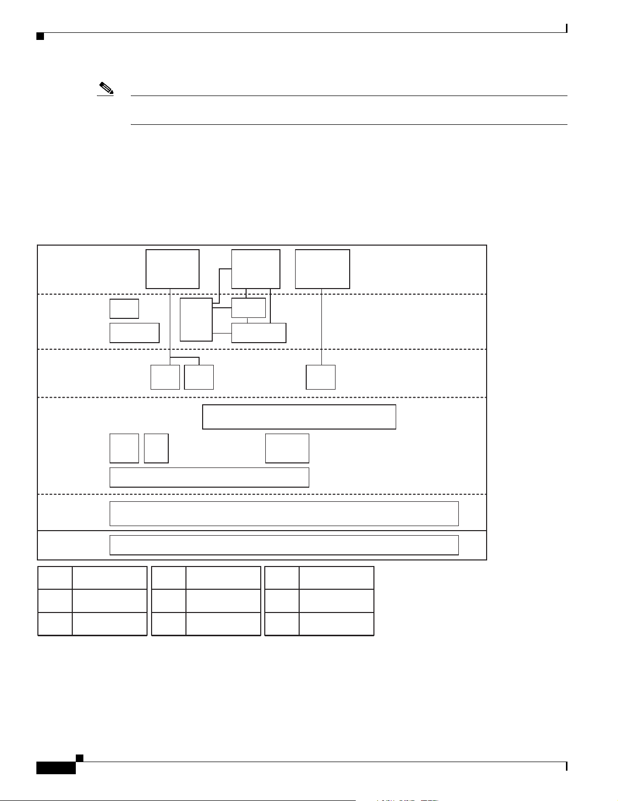
Figure 1-1 displays the software architecture of the protocols and APIs that HCAs support. The figure
displays ULPs and APIs in relation to other IB software elements.
Figure 1-1 HCA Supported Protocols and API Architecture
Chapter 1 About Host Drivers
Application
Level
User
APIs
Upper
Layer
Protocol
Mid-Layer
Provider
Hardware
Diag
Tools
User Level
MAD API
SA
Client
IP Based
App
Access
Various
MPI's
SDPIPoIB
SMA
InfiniBand Verbs / API
MPI Based
App Access
uDAPL
User Level
Verbs / API
Connection Manager
Abstraction (CMA)
Connection
Manager
Hardware
Specific Driver
InfiniBand HC A
Block
Storage
Access
User Space
Kernel Space
SRP
SDP
SRP
1-2
IP over InfiniBandIPoIB
Sockets Direct
Protocol
SCSI RDMA
Protocol (Initiator)
Cisco SFS InfiniBand Host Drivers User Guide for Linux
MPI
UDAPL
SA
Message Pass ing
Interface
User Direct Access
Programming Lib
Subnet
Administrator
MAD
SMA
HCA
Management
Datagram
Subnet Manager
Agent
Host Channel
Adapter
180411
OL-12309-01
Page 13

Chapter 1 About Host Drivers
Supported Protocols
This section describes the supported protocols and includes the following topics:
• IPoIB
• SRP
• SDP
Protocol here refers to software in the networking layer in kernel space.
IPoIB
The IPoIB protocol passes IP traffic over the IB network. Configuring IPoIB requires similar steps to
configuring IP on an Ethernet network. SDP relies on IPoIB to resolve IP addresses. (See the “SDP”
section on page 1-3.)
To configure IPoIB, you assign an IP address and subnet mask to each IB port. IPoIB automatically adds
IB interface names to the IP network configuration. To configure IPoIB, see Chapter 3, “IP over IB
Protocol.”
Supported Protocols
SRP
SDP
SRP runs SCSI commands across RDMA-capable networks so that IB hosts can communicate with Fibre
Channel storage devices and IB-attached storage devices. SRP requires an SFS with a Fibre Channel
gateway to connect the host to Fibre Channel storage. In conjunction with an SFS, SRP disguises
IB-attached hosts as Fibre Channel-attached hosts. The topology transparency feature lets Fibre Channel
storage communicate seamlessly with IB-attached hosts (known as SRP hosts). For configuration
instructions, see Chapter 4, “SCSI RDMA Protocol.”
SDP is an IB-specific upper- layer protocol. It defines a standard wire protocol to support stream sockets
networking over IB. SDP enables sockets-based applications to take advantage of the enhanced
performance features provided by IB and achieves lower latency and higher bandwidth than IPoIB
running sockets-based applications. It provides a high-performance, data transfer protocol for
stream-socket networking over an IB fabric. You can configure the driver to automatically translate TCP
to SDP based on a source IP, a destination, or an application name. For configuration instructions, see
Chapter 5, “Sockets Direct Protocol.”
OL-12309-01
Cisco SFS InfiniBand Host Drivers User Guide for Linux
1-3
Page 14

Supported APIs
Supported APIs
This section describes the supported APIs and includes the following topics:
• MVAPICH MPI
• uDAPL
• Intel MPI
• HP MPI
API refers to software in the networking layer in user space.
MVAPICH MPI
MPI is a standard library functionality in C, C++, and Fortran that can be used to implement a
message-passing program. MPI allows the coordination of a program running as multiple processes in a
distributed memory environment. This document includes setup and configuration information for
MVAPICH MPI. For more information, see Chapter 7, “MVAPICH MPI.”
Chapter 1 About Host Drivers
uDAPL
uDAPL defines a single set of user-level APIs for all RDMA-capable transports. The uDAPL mission is
to define a transport-independent and platform-standard set of APIs that exploits RDMA capabilities
such as those present in IB. For more information, see Chapter 6, “uDAPL.”
Intel MPI
Cisco tests and supports the SFS IB host drivers with Intel MPI. The Intel MPI implementation is
available for separate purchase from Intel. For more information, visit the following URL:
http://www.intel.com/go/mpi
HP MPI
Cisco tests and supports the SFS IB host drivers with HP MPI for Linux. The HP MPI implementation
is available for separate purchase from Hewlett Packard. For more information, visit the following URL:
http://www.hp.com/go/mpi
HCA Utilities and Diagnostics
1-4
The HCA utilities provide basic tools to view HCA attributes and run preliminary troubleshooting tasks.
For more information, see Chapter 8, “HCA Utilities and Diagnostics.”
Cisco SFS InfiniBand Host Drivers User Guide for Linux
OL-12309-01
Page 15

Note See the “Root and Non-root Conventions in Examples” section on page ix for details about the
Introduction
CHA P T ER
Installing Host Drivers
The chapter includes the following sections:
• Introduction, page 2-1
• Contents of ISO Image, page 2-2
• Installing Host Drivers from an ISO Image, page 2-2
• Uninstalling Host Drivers from an ISO Image, page 2-3
significance of prompts used in the examples in this chapter.
2
The Cisco Linux IB driver is delivered as an ISO image. The ISO image contains the binary RPMs for
selected Linux distributions. The Cisco Linux IB drivers distribution contains an installation script
called tsinstall. The install script performs the necessary steps to accomplish the following:
• Discover the currently installed kernel
• Uninstall any IB stacks that are part of the standard operating system distribution
• Install the Cisco binary RPMs if they are available for the current kernel
• Identify the currently installed IB HCA and perform the required firmware updates
Note For specific details about which binary RPMs are included and which standard Linux distributions and
kernels are currently supported, see the Release Notes for Linux Host Drivers Release 3.2.0.
OL-12309-01
Cisco SFS InfiniBand Host Drivers User Guide for Linux
2-1
Page 16

Contents of ISO Image
Contents of ISO Image
The ISO image contains the following directories and files:
• docs/
This directory contains the related documents.
• tsinstall
This is the installation script.
• redhat/
This directory contains the binary RPMs for Red Hat Enterprise Linux.
• suse/
This directory contains the binary RPMs for SUSE Linux Enterprise Server.
Installing Host Drivers from an ISO Image
Chapter 2 Installing Host Drivers
See the Cisco InfiniBand Host Channel Adapter Hardware Installation Guide to correctly install HCAs.
To install host drivers from an ISO image, perform the following steps:
Note If you upgrade your Linux kernel after installing these host drivers, you need to reinstall the host drivers.
Step 1 Verify that the system has a viable HCA installed by ensuring that you can see the InfiniHost entries in
the display.
The following example shows that the installed HCA is viable:
host1# lspci -v | grep Mellanox
06:01.0 PCI bridge: Mellanox Technologies MT23108 PCI Bridge (rev a0) (prog-if 00 [Normal
decode])
07:00.0 InfiniBand: Mellanox Technologies MT23108 InfiniHost (rev a0)
Subsystem: Mellanox Technologies MT23108 InfiniHost
Step 2 Download an ISO image, and copy it to your network.
You can download an ISO image from http://www.cisco.com/cgi-bin/tablebuild.pl/sfs-linux
Step 3 Use the md5sum utility to confirm the file integrity of your ISO image.
Step 4 Install drivers from an ISO image on your network.
The following example shows how to install host drivers from an ISO image:
host1# mount -o ro,loop topspin-host-3.2.0-136.iso /mnt
host1# /mnt/tsinstall
The following kernels are installed, but do not have drivers available:
2.6.9-34.EL.x86_64
The following installed packages are out of date and will be upgraded:
topspin-ib-rhel4-3.2.0-118.x86_64
topspin-ib-mpi-rhel4-3.2.0-118.x86_64
topspin-ib-mod-rhel4-2.6.9-34.ELsmp-3.2.0-118.x86_64
The following packages will be installed:
topspin-ib-rhel4-3.2.0-136.x86_64 (libraries, binaries, etc)
2-2
Cisco SFS InfiniBand Host Drivers User Guide for Linux
OL-12309-01
Page 17

Chapter 2 Installing Host Drivers
topspin-ib-mpi-rhel4-3.2.0-136.x86_64 (MPI libraries, source code, docs, etc)
topspin-ib-mod-rhel4-2.6.9-34.ELsmp-3.2.0-136.x86_64 (kernel modules)
installing 100% ###############################################################
Upgrading HCA 0 HCA.LionMini.A0 to firmware build 3.2.0.136
New Node GUID = 0005ad0000200848
New Port1 GUID = 0005ad0000200849
New Port2 GUID = 0005ad000020084a
Programming HCA firmware... Flash Image Size = 355076
Flashing - EFFFFFFFEPPPPPPPEWWWWWWWEWWWWWWWEWWWWWVVVVVVVVVVVVVVVVVVVVVVVVVVVVVV
Flash verify passed!
Step 5 Run a test to verify whether or not the IB link is established between the respective host and the IB
switch.
The following example shows a test run that verifies an established IB link:
host1# /usr/local/topspin/sbin/hca_self_test
---- Performing InfiniBand HCA Self Test ----
Number of HCAs Detected ................ 1
PCI Device Check ....................... PASS
Kernel Arch ............................ x86_64
Host Driver Version .................... rhel4-2.6.9-34.ELsmp-3.2.0-136
Host Driver RPM Check .................. PASS
HCA Type of HCA #0 ..................... LionMini
HCA Firmware on HCA #0 ................. v5.2.000 build 3.2.0.136 HCA.LionMini.A0
HCA Firmware Check on HCA #0 ........... PASS
Host Driver Initialization ............. PASS
Number of HCA Ports Active ............. 2
Port State of Port #0 on HCA #0 ........ UP 4X
Port State of Port #1 on HCA #0 ........ UP 4X
Error Counter Check on HCA #0 .......... PASS
Kernel Syslog Check .................... PASS
Node GUID .............................. 00:05:ad:00:00:20:08:48
------------------ DONE ---------------------
Uninstalling Host Drivers from an ISO Image
The HCA test script, as shown in the example above, checks for the HCA firmware version, verifies that
proper kernel modules are loaded on the IP drivers, shows the state of the HCA ports, shows the counters
that are associated with each IB port, and indicates whether or not there are any error messages in the
host operating system log files.
Note To troubleshoot the results of this test, see Chapter 8, “HCA Utilities and Diagnostics.”
Uninstalling Host Drivers from an ISO Image
The following example shows how to uninstall a host driver from a device:
host1# rpm -e `rpm -qa | grep topspin`
OL-12309-01
Cisco SFS InfiniBand Host Drivers User Guide for Linux
2-3
Page 18

Uninstalling Host Drivers from an ISO Image
Chapter 2 Installing Host Drivers
2-4
Cisco SFS InfiniBand Host Drivers User Guide for Linux
OL-12309-01
Page 19

CHA P T ER
3
IP over IB Protocol
This chapter describes IP over IB protocol and includes the following sections:
• Introduction, page 3-1
• Manually Configuring IPoIB for Default IB Partition, page 3-2
• Subinterfaces, page 3-2
• Verifying IPoIB Functionality, page 3-5
• IPoIB Performance, page 3-6
• Sample Startup Configuration File, page 3-8
• IPoIB High Availability, page 3-8
Note See the “Root and Non-root Conventions in Examples” section on page ix for details about the
significance of prompts used in the examples in this chapter.
Introduction
Note To enable these IPoIB settings across reboots, you must explicitly add these settings to the networking
OL-12309-01
Configuring IPoIB requires that you follow similar steps to the steps used for configuring IP on an
Ethernet network. When you configure IPoIB, you assign an IP address and a subnet mask to each HCA
port. The first HCA port on the first HCA in the host is the ib0 interface, the second port is ib1, and so on.
interface startup configuration file. For a sample configuration file, see the “Sample Startup
Configuration File” section on page 3-8.
See your Linux distribution documentation for additional information about configuring IP addresses.
Cisco SFS InfiniBand Host Drivers User Guide for Linux
3-1
Page 20

Manually Configuring IPoIB for Default IB Partition
Manually Configuring IPoIB for Default IB Partition
To manually configure IPoIB for the default IB partition, perform the following steps:
Step 1 Log in to your Linux host.
Step 2 To configure the interface, enter the ifconfig command with the following items:
• The appropriate IB interface (ib0 or ib1 on a host with one HCA)
• The IP address that you want to assign to the interface
• The netmask keyword
• The subnet mask that you want to assign to the interface
The following example shows how to configure an IB interface:
host1# ifconfig ib0 192.168.0.1 netmask 255.255.252.0
Step 3 (Optional) Verify the configuration by entering the ifconfig command with the appropriate port identifier
ib# argument.
The following example shows how to verify the configuration:
host1# ifconfig ib0
ib0 Link encap:Ethernet HWaddr F8:79:D1:23:9A:2B
inet addr:192.168.0.1 Bcast:192.168.0.255 Mask:255.255.255.0
inet6 addr: fe80::9879:d1ff:fe20:f4e7/64 Scope:Link
UP BROADCAST RUNNING MULTICAST MTU:2044 Metric:1
RX packets:0 errors:0 dropped:0 overruns:0 frame:0
TX packets:0 errors:0 dropped:9 overruns:0 carrier:0
collisions:0 txqueuelen:1024
RX bytes:0 (0.0 b) TX bytes:0 (0.0 b)
Chapter 3 IP over IB Protocol
Step 4 Repeat Step 2 and Step 3 on the remaining interface(s).
Subinterfaces
This section describes subinterfaces. Subinterfaces divide primary (parent) interfaces to provide traffic
isolation. Partition assignments distinguish subinterfaces from parent interfaces. The default Partition
Key (p_key), ff:ff, applies to the primary (parent) interface.
This section includes the following topics:
• Creating a Subinterface Associated with a Specific IB Partition, page 3-3
• Removing a Subinterface Associated with a Specific IB Partition, page 3-4
3-2
Cisco SFS InfiniBand Host Drivers User Guide for Linux
OL-12309-01
Page 21

Chapter 3 IP over IB Protocol
Creating a Subinterface Associated with a Specific IB Partition
To create a subinterface associated with a specific IB partition, perform the following steps:
Step 1 Create a partition on an IB SFS. Alternatively, you can choose to create the partition of the IB interface
on the host first, and then create the partition for the ports on the IB SFS. See the Cisco SFS Product
Family Element Manager User Guide for information regarding valid partitions on the IB SFS.
Step 2 Log in to your host.
Step 3 Add the value of the partition key to the file as root user.
The following example shows how to add partition 80:02 to the primary interface ib0:
host1# /usr/local/topspin/sbin/ipoibcfg add ib0 80:02
Step 4 Verify that the interface is set up by ensuring that ib0.8002 is displayed.
The following example shows how to verify the interface:
host1# ls /sys/class/net
eth0 ib0 ib0.8002 ib1 lo sit0
Subinterfaces
Step 5 Verify that the interface was created by entering the ifconfig -a command.
The following example shows how to enter the ifconfig -a command:
host1# ifconfig -a
eth0 Link encap:Ethernet HWaddr 00:30:48:20:D5:D1
inet addr:172.29.237.206 Bcast:172.29.239.255 Mask:255.255.252.0
inet6 addr: fe80::230:48ff:fe20:d5d1/64 Scope:Link
UP BROADCAST RUNNING MULTICAST MTU:1500 Metric:1
RX packets:9091465 errors:0 dropped:0 overruns:0 frame:0
TX packets:505050 errors:0 dropped:0 overruns:0 carrier:0
collisions:0 txqueuelen:1000
RX bytes:1517373743 (1.4 GiB) TX bytes:39074067 (37.2 MiB)
Base address:0x3040 Memory:dd420000-dd440000
ib0 Link encap:Ethernet HWaddr F8:79:D1:23:9A:2B
inet addr:192.168.0.1 Bcast:192.168.0.255 Mask:255.255.255.0
inet6 addr: fe80::9879:d1ff:fe20:f4e7/64 Scope:Link
UP BROADCAST RUNNING MULTICAST MTU:2044 Metric:1
RX packets:0 errors:0 dropped:0 overruns:0 frame:0
TX packets:0 errors:0 dropped:9 overruns:0 carrier:0
collisions:0 txqueuelen:1024
RX bytes:0 (0.0 b) TX bytes:0 (0.0 b)
ib0.8002 Link encap:Ethernet HWaddr 00:00:00:00:00:00
BROADCAST MULTICAST MTU:2044 Metric:1
RX packets:0 errors:0 dropped:0 overruns:0 frame:0
TX packets:0 errors:0 dropped:0 overruns:0 carrier:0
collisions:0 txqueuelen:1024
RX bytes:0 (0.0 b) TX bytes:0 (0.0 b)
lo Link encap:Local Loopback
inet addr:127.0.0.1 Mask:255.0.0.0
inet6 addr: ::1/128 Scope:Host
UP LOOPBACK RUNNING MTU:16436 Metric:1
RX packets:378 errors:0 dropped:0 overruns:0 frame:0
TX packets:378 errors:0 dropped:0 overruns:0 carrier:0
collisions:0 txqueuelen:0
RX bytes:45730 (44.6 KiB) TX bytes:45730 (44.6 KiB)
sit0 Link encap:IPv6-in-IPv4
OL-12309-01
Cisco SFS InfiniBand Host Drivers User Guide for Linux
3-3
Page 22

Chapter 3 IP over IB Protocol
Subinterfaces
NOARP MTU:1480 Metric:1
RX packets:0 errors:0 dropped:0 overruns:0 frame:0
TX packets:0 errors:0 dropped:0 overruns:0 carrier:0
collisions:0 txqueuelen:0
RX bytes:0 (0.0 b) TX bytes:0 (0.0 b)
Verify that you see the ib0.8002 output.
Step 6 Configure the new interface just as you would the parent interface. (See the “Manually Configuring
IPoIB for Default IB Partition” section on page 3-2.)
The following example shows how to configure the new interface:
host1# ifconfig ib0.8002 192.168.12.1 netmask 255.255.255.0
Removing a Subinterface Associated with a Specific IB Partition
To remove a subinterface, perform the following steps:
Step 1 Take the subinterface offline. You cannot remove a subinterface until you bring it down.
The following example shows how to take the subinterface offline:
host1# ifconfig ib0.8002 down
Step 2 Remove the value of the partition key to the file as root user.
The following example shows how to remove the partition 80:02 from the primary interface ib0:
host1# /usr/local/topspin/sbin/ipoibcfg del ib0 80:02
Step 3 (Optional) Verify that the subinterface no longer appears in the interface list by entering the ifconfig -a
command.
The following example shows how to verify that the subinterface no longer appears in the interface list:
host1# ifconfig -a
eth0 Link encap:Ethernet HWaddr 00:30:48:20:D5:D1
inet addr:172.29.237.206 Bcast:172.29.239.255 Mask:255.255.252.0
inet6 addr: fe80::230:48ff:fe20:d5d1/64 Scope:Link
UP BROADCAST RUNNING MULTICAST MTU:1500 Metric:1
RX packets:9091465 errors:0 dropped:0 overruns:0 frame:0
TX packets:505050 errors:0 dropped:0 overruns:0 carrier:0
collisions:0 txqueuelen:1000
RX bytes:1517373743 (1.4 GiB) TX bytes:39074067 (37.2 MiB)
Base address:0x3040 Memory:dd420000-dd440000
ib0 Link encap:Ethernet HWaddr F8:79:D1:23:9A:2B
inet addr:192.168.0.1 Bcast:192.168.0.255 Mask:255.255.255.0
inet6 addr: fe80::9879:d1ff:fe20:f4e7/64 Scope:Link
UP BROADCAST RUNNING MULTICAST MTU:2044 Metric:1
RX packets:0 errors:0 dropped:0 overruns:0 frame:0
TX packets:0 errors:0 dropped:9 overruns:0 carrier:0
collisions:0 txqueuelen:1024
RX bytes:0 (0.0 b) TX bytes:0 (0.0 b)
ib0.8002 Link encap:Ethernet HWaddr 00:00:00:00:00:00
BROADCAST MULTICAST MTU:2044 Metric:1
RX packets:0 errors:0 dropped:0 overruns:0 frame:0
3-4
Cisco SFS InfiniBand Host Drivers User Guide for Linux
OL-12309-01
Page 23

Chapter 3 IP over IB Protocol
TX packets:0 errors:0 dropped:0 overruns:0 carrier:0
collisions:0 txqueuelen:1024
RX bytes:0 (0.0 b) TX bytes:0 (0.0 b)
lo Link encap:Local Loopback
inet addr:127.0.0.1 Mask:255.0.0.0
inet6 addr: ::1/128 Scope:Host
UP LOOPBACK RUNNING MTU:16436 Metric:1
RX packets:378 errors:0 dropped:0 overruns:0 frame:0
TX packets:378 errors:0 dropped:0 overruns:0 carrier:0
collisions:0 txqueuelen:0
RX bytes:45730 (44.6 KiB) TX bytes:45730 (44.6 KiB)
sit0 Link encap:IPv6-in-IPv4
NOARP MTU:1480 Metric:1
RX packets:0 errors:0 dropped:0 overruns:0 frame:0
TX packets:0 errors:0 dropped:0 overruns:0 carrier:0
collisions:0 txqueuelen:0
RX bytes:0 (0.0 b) TX bytes:0 (0.0 b)
Verifying IPoIB Functionality
Verifying IPoIB Functionality
To verify your configuration and your IPoIB functionality, perform the following steps:
Step 1 Log in to your hosts.
Step 2 Verify the IPoIB functionality by using the ifconfig command.
The following example shows how two IB nodes are used to verify IPoIB functionality. In the following
example, IB node 1 is at 192.168.0.1, and IB node 2 is at 192.168.0.2:
host1# ifconfig ib0 192.168.0.1 netmask 255.255.252.0
host2# ifconfig ib0 192.168.0.2 netmask 255.255.252.0
Step 3 Enter the ping command from 192.168.0.1 to 192.168.0.2.
The following example shows how to enter the ping command:
host1# ping -c 5 192.168.0.2
PING 192.168.0.2 (192.168.0.2) 56(84) bytes of data.
64 bytes from 192.168.0.2: icmp_seq=0 ttl=64 time=0.079 ms
64 bytes from 192.168.0.2: icmp_seq=1 ttl=64 time=0.044 ms
64 bytes from 192.168.0.2: icmp_seq=2 ttl=64 time=0.055 ms
64 bytes from 192.168.0.2: icmp_seq=3 ttl=64 time=0.049 ms
64 bytes from 192.168.0.2: icmp_seq=4 ttl=64 time=0.065 ms
--- 192.168.0.2 ping statistics --5 packets transmitted, 5 received, 0% packet loss, time 3999ms rtt min/avg/max/mdev =
0.044/0.058/0.079/0.014 ms, pipe 2
OL-12309-01
Cisco SFS InfiniBand Host Drivers User Guide for Linux
3-5
Page 24

IPoIB Performance
IPoIB Performance
This section describes how to verify IPoIB performance by running the Bandwidth test and the Latency
test. These tests are described in detail at the following URL:
http://www.netperf.org/netperf/training/Netperf.html
To verify IPoIB performance, perform the following steps:
Step 1 Download Netperf from the following URL:
http://www.netperf.org/netperf/NetperfPage.html
Step 2 Compile Netperf by following the instructions at http://www.netperf.org/netperf/NetperfPage.html.
Step 3 Start the Netperf server.
The following example shows how to start the Netperf server:
host1$ netserver
Starting netserver at port 12865
Starting netserver at hostname 0.0.0.0 port 12865 and family AF_UNSPEC
host1$
Chapter 3 IP over IB Protocol
Step 4 Run the Netperf client. The default test is the Bandwidth test.
The following example shows how to run the Netperf client, which starts the Bandwidth test by default:
host2$ netperf -H 192.168.0.1 -c -C -- -m 65536
TCP STREAM TEST from 0.0.0.0 (0.0.0.0) port 0 AF_INET to 192.168.0.1 (192.168.0.1) port 0
AF_INET
Recv Send Send Utilization Service Demand
Socket Socket Message Elapsed Send Recv Send Recv
Size Size Size Time Throughput local remote local remote
bytes bytes bytes secs. 10^6bits/s % S % S us/KB us/KB
87380 16384 65536 10.00 2701.06 46.93 48.73 5.694 5.912
Note You must specify the IPoIB IP address when running the Netperf client.
The following list describes parameters for the netperf command:
-H Where to find the server
192.168.0.1 IPoIB IP address
-c Client CPU utilization
-C Server CPU utilization
-- Separates the global and test-specific parameters
-m Message size, which is 65536 in the example above
3-6
The notable performance values in the example above are as follows:
Throughput is 2.70 gigabits per second.
Client CPU utilization is 46.93 percent of client CPU.
Server CPU utilization is 48.73 percent of server CPU.
Cisco SFS InfiniBand Host Drivers User Guide for Linux
OL-12309-01
Page 25

Chapter 3 IP over IB Protocol
Step 5 Run the Netperf Latency test.
Run the test once, and stop the server so that it does not repeat the test.
The following example shows how to run the Latency test, and then stop the Netperf server:
host2$ netperf -H 192.168.0.1 -c -C -t TCP_RR -- -r 1,1
TCP REQUEST/RESPONSE TEST from 0.0.0.0 (0.0.0.0) port 0 AF_INET to 192.168.0.1
(192.168.0.1) port 0 AF_INET
Local /Remote
Socket Size Request Resp. Elapsed Trans. CPU CPU S.dem S.dem
Send Recv Size Size Time Rate local remote local remote
bytes bytes bytes bytes secs. per sec % S % S us/Tr us/Tr
16384 87380 1 1 10.00 17228.96 12.98 12.30 30.146 28.552
16384 87380
The following list describes parameters for the netperf command:
-H Where to find the server
192.168.0.1 IPoIB IP address
-c Client CPU utilization
-C Server CPU utilization
-t Test type
TCP_RR TCP required response test
-- Separates the global and test-specific parameters
-r 1,1 The request size sent and how many bytes requested back
IPoIB Performance
The notable performance values in the example above are as follows:
Client CPU utilization is 12.98 percent of client CPU.
Server CPU utilization is 12.30 percent of server CPU.
Latency is 29.02 microseconds. Latency is calculated as follows:
(1 / Transaction rate per second) / 2 * 1,000,000 = one-way average latency in microseconds
Step 6 To end the test, shut down the Netperf server.
host1$ pkill netserver
OL-12309-01
Cisco SFS InfiniBand Host Drivers User Guide for Linux
3-7
Page 26

Sample Startup Configuration File
Sample Startup Configuration File
IP addresses that are configured manually are not persistent across reboots. You must use a configuration
file to configure IPoIB when the host boots. Two sample configurations are included in this section.
The following sample configuration shows an example file named ifcfg-ib0 that resides on a Linux host
in /etc/sysconfig/networks-scripts/ on RHEL3 and RHEL4. The configuration file configures an IP
address at boot time.
host1# cat > /etc/sysconfig/network-scripts/ifcfg-ib0 << EOF
> DEVICE=ib0
> BOOTPROTO=static
> IPADDR=192.168.0.1
> NETMASK=255.255.255.0
> ONBOOT=yes
> EOF
The following sample configuration shows an example file named ifcfg-ib0 in /etc/sysconfig/network/
on SLES10. The configuration file configures an IP address at boot time.
host1# cat > /etc/sysconfig/network/ifcfg-ib0 << EOF
> DEVICE=ib0
> BOOTPROTO=static
> IPADDR=192.168.0.1
> NETMASK=255.255.255.0
> STARTMODE=auto
> EOF
Chapter 3 IP over IB Protocol
IPoIB High Availability
This section describes IPoIB high availability. IPoIB supports active/passive port failover high
availability between two or more ports. When you enable the high availability feature, the ports on the
HCA (for example, ib0 and ib1) merge into one virtual port. If you configure high availability between
the ports on the HCA(s), only one of the physical ports passes traffic. The other ports are used as standby
in the event of a failure. This section includes the following topics:
• Merging Physical Ports
• Unmerging Physical Ports
Merging Physical Ports
To configure IPoIB high availability on HCA ports in a Linux host, perform the following steps:
Step 1 Log in to your Linux host.
Step 2 Display the available interfaces by entering the ipoibcfg list command. The following example shows
how to configure IPoIB high availability between two ports on one HCA.
The following example shows how to display the available interfaces:
host1# /usr/local/topspin/sbin/ipoibcfg list
ib0 (P_Key 0xffff) (SL:255) (Ports: InfiniHost0/1, Active: InfiniHost0/1)
ib1 (P_Key 0xffff) (SL:255) (Ports: InfiniHost0/2, Active: InfiniHost0/2)
3-8
Cisco SFS InfiniBand Host Drivers User Guide for Linux
OL-12309-01
Page 27

Chapter 3 IP over IB Protocol
Step 3 Take the interfaces offline. You cannot merge interfaces until you bring them down.
The following example shows how to take the interfaces offline:
host1# ifconfig ib0 down
host1# ifconfig ib1 down
Step 4 Merge the two ports into one virtual IPoIB high availability port by entering the ipoibcfg merge
command with the IB identifiers of the first and the second IB ports on the HCA.
The following example shows how to merge the two ports into one virtual IPoIB high availability port:
host1# /usr/local/topspin/sbin/ipoibcfg merge ib0 ib1
Step 5 Display the available interfaces by entering the ipoibcfg list command.
The following example shows how to display the available interfaces:
host1# /usr/local/topspin/sbin/ipoibcfg list
ib0 (P_Key 0xffff) (SL:255) (Ports: InfiniHost0/1, Active: InfiniHost0/1)
Note The ib1 interface no longer appears, as it is merged with ib0.
IPoIB High Availability
Step 6 Enable the interface by entering the ifconfig command with the appropriate port identifier ib# argument
and the up keyword.
The following example shows how to enable the interface with the ifconfig command:
host1# ifconfig ib0 up
Step 7 Assign an IP address to the merged port just as you would assign an IP address to a standard interface.
Unmerging Physical Ports
To unmerge physical ports and disable active-passive IPoIB high availability, perform the following
steps:
Step 1 Disable the IPoIB high availability interface that you want to unmerge by entering the ifconfig command
with the appropriate IB interface argument and the down argument.
The following example shows how to unmerge by disabling the IPoIB high availability interface:
host1# ifconfig ib0 down
Step 2 Unmerge the port by entering the ipoibcfg unmerge command with the identifier of the port that you
want to unmerge.
The following example shows how to unmerge the port:
host1# /usr/local/topspin/sbin/ipoibcfg unmerge ib0 ib1
OL-12309-01
Note After the unmerge, ib1 no longer has an IP address and needs to be configured.
Cisco SFS InfiniBand Host Drivers User Guide for Linux
3-9
Page 28

IPoIB High Availability
Step 3 Display the available interfaces by entering the ipoibcfg list command.
Step 4 Enable the interfaces by entering the ifconfig command with the appropriate IB interface argument and
Chapter 3 IP over IB Protocol
The following example shows how to display the available interfaces:
host1# /usr/local/topspin/sbin/ipoibcfg list
ib0 (P_Key 0xffff) (SL:255) (Ports: InfiniHost0/1, Active: InfiniHost0/1)
ib1 (P_Key 0xffff) (SL:255) (Ports: InfiniHost0/2, Active: InfiniHost0/2)
the up argument.
The following example shows how to enable the interfaces:
host1# ifconfig ib0 up
3-10
Cisco SFS InfiniBand Host Drivers User Guide for Linux
OL-12309-01
Page 29

Note See the “Root and Non-root Conventions in Examples” section on page ix for details about the
Introduction
CHA P T ER
4
SCSI RDMA Protocol
This chapter describes SCSI RDMA protocol and includes the following sections:
• Introduction, page 4-1
• Configuring SRP, page 4-1
• Verifying SRP, page 4-7
significance of prompts used in the examples in this chapter.
SRP runs SCSI commands across RDMA-capable networks so that IB hosts can communicate with Fibre
Channel storage devices and IB-attached storage devices. SRP requires an SFS with a Fibre Channel
gateway to connect the host to Fibre Channel storage. In conjunction with an SFS, SRP masks
IB-attached hosts as Fibre Channel-attached hosts. The topology transparency feature enables Fibre
Channel storage to communicate seamlessly with IB-attached hosts, called SRP hosts.
To connect an IB-attached SRP host to a SAN, cable your SRP host to an IB fabric that includes an SFS
with a Fibre Channel gateway or IB-attached storage. Log in to the SFS to configure the Fibre Channel
connection between the SAN and the SRP host, and then log in to the host and configure the SRP host.
Configuring SRP
This section describes how to configure SRP. There are a number of ways to configure the connection
between the SAN and the SRP host. The method that you choose depends on the interfaces available to
you and the global access settings on your SFS. The instructions in this section provide one example of
how to configure the connection. For detailed instructions, see the Cisco SFS InfiniBand Fibre Channel
Gateway User Guide.
Note If you have a Fibre Channel gateway, you must configure ITLs. If you have IB-attached storage, see the
relevant storage documentation.
OL-12309-01
Cisco SFS InfiniBand Host Drivers User Guide for Linux
4-1
Page 30

Configuring SRP
This section contains information on how to configure your IB fabric to connect an SRP host to a SAN
and includes the following topics:
• Configuring ITLs when Using Fibre Channel Gateway, page 4-2
• Configuring SRP Host, page 4-6
Note If you intend to manage your environment with Cisco VFrame software, do not configure ITLs.
Configuring ITLs when Using Fibre Channel Gateway
This section describes how to configure ITLs when using Fibre Channel gateway. When you configure
initiators, you assign Fibre Channel WWNNs to SRP hosts so that the SAN can recognize the hosts.
Steps to configure initiators are provided in this section.
To configure initiators that you have not yet connected to your fabric, enter the GUID of the initiator into
the CLI or Element Manager so that the configuration works when you connect the SRP host.
You must configure ITLs for your initiators to communicate with your storage. You can configure ITLs
with the CLI or the Element Manager GUI.
Chapter 4 SCSI RDMA Protocol
• If you restricted port and LUN access when you configured global attributes, proceed to the
“Configuring ITLs with Element Manager while Global Policy Restrictions Apply” section on
page 4-4.
• If you have not configured access, perform the steps as appropriate in “Configuring ITLs with
Element Manager while No Global Policy Restrictions Apply” section on page 4-2 or in
“Configuring ITLs with Element Manager while Global Policy Restrictions Apply” section on
page 4-4.
Note If you enter a Fibre Channel command and receive an error message that reads Operation temporarily
failed - try again
, give your Fibre Channel gateway time to finish initializing, and then retry the
command.
Configuring ITLs with Element Manager while No Global Policy Restrictions Apply
This section describes how to configure ITLs with Element Manager while no global policy restrictions
apply. To configure ITLs with a Linux SRP host while your port masking and LUN masking policies are
unrestricted, perform the following steps:
Step 1 Log in to your host.
Step 2 Display the host GUID by entering the hca_self_test | grep -i guid command.
4-2
Note Record the GUID value (always similar format 00:00:00:00:00:00:00:00). You are required later
to enter it repeatedly.
Cisco SFS InfiniBand Host Drivers User Guide for Linux
OL-12309-01
Page 31

Chapter 4 SCSI RDMA Protocol
Step 3 Bring up the Fibre Channel gateways on your SFS, by performing the following steps:
a. Launch Element Manager.
b. Double-click the Fibre Channel gateway card that you want to bring up. The Fibre Channel Card
c. Click the Up radio button in the Enable/Disable Card field, and then click Apply.
d. (Optional) Repeat this process for additional gateways.
The Fibre Channel gateway automatically discovers all attached storage.
Note Discovered LUs remain gray (inactive) until an SRP host connects to them. Once a host connects
Step 4 From the Fibre Channel menu of the Element Manager, choose Storage Manager. The Cisco Storage
Manager window opens.
Step 5 Click the SRP Hosts folder in the Storage navigation tree in the left-hand frame of the interface. The
SRP Hosts display appears in the right-hand frame of the interface.
Step 6 Click Define New in the SRP Hosts display. The Define New SRP Host window opens.
Configuring SRP
window opens.
to an LU, its icon becomes blue (active). Hosts do not stay continually connected to LUs, so the
color of the icon may change.
Note If your host includes multiple HCAs, you must configure each individual HCA as an initiator.
When you configure one HCA in a host, other HCAs in the host are not automatically
configured.
Step 7 Choose a GUID from the Host GUID drop-down menu in the Define New SRP Host window. The menu
displays the GUIDs of all connected hosts that you have not yet configured as initiators.
Step 8 (Optional) Type a description in the Description field in the Define New SRP Host window.
Step 9 Click the Next > button. The Define New SRP Host window displays a recommended WWNN for the
host and recommended WWPNs that represent the host on all existing and potential Fibre Channel
gateway ports.
Note Although you can manually configure the WWNN or WWPNs, use the default values to avoid
conflicts.
Step 10 Click the Finish button. The new host appears in the SRP Hosts display.
Step 11 Expand the SRP Hosts folder in the Storage navigation tree, and then click the host that you created.
The host display appears in the right-hand frame of the interface.
Step 12 (Optional) Click the LUN Access tab in the host display, and then click Discover LUNs. The targets and
associated LUNs that your Fibre Channel gateway sees appear in the Accessible LUNs field.
Step 13 Click Refresh in the Cisco Storage Manager window.
OL-12309-01
Cisco SFS InfiniBand Host Drivers User Guide for Linux
4-3
Page 32

Chapter 4 SCSI RDMA Protocol
Configuring SRP
Configuring ITLs with Element Manager while Global Policy Restrictions Apply
This section describes how to configure ITLs with Element Manager while global policy restrictions
apply. These instructions apply to environments where the portmask policy and LUN masking policy are
both restricted. To verify that you have restricted your policies, enter the
at the CLI prompt. View the default-gateway-portmask-policy and default-lun-policy fields. If
restrictions apply to either field, restricted appears in the field output.
To configure ITLs with a Linux SRP host while your port masking and LUN masking policies are
restricted, perform the following steps:
Step 1 Log in to your host.
Step 2 Display the host GUID by entering the hca_self_test | grep -i guid command at the host CLI.
Note Record the GUID value. You are required later to enter it repeatedly.
Step 3 Bring up the Fibre Channel gateways on your server switch with the following steps:
a. Launch Element Manager.
b. Double-click the Fibre Channel gateway card that you want to bring up. The Fibre Channel Card
window opens.
show fc srp-global
command
c. Click the Up radio button in the Enable/Disable Card field, and then click Apply.
d. (Optional) Repeat this process for additional gateways.
The Fibre Channel gateway automatically discovers all attached storage.
Note Discovered LUs remain gray (inactive) until an SRP host connects to them. Once a host connects
to an LU, its icon becomes blue (active).
Step 4 From the Fibre Channel menu, select Storage Manager.
Step 5 Click the SRP Hosts folder in the Storage navigation tree in the left-hand frame of the interface. The
SRP Hosts display appears in the right-hand frame of the interface.
Step 6 Click Define New in the SRP Hosts display. The Define New SRP Host window opens.
Note If your host includes multiple HCAs, you must configure each individual HCA as an initiator.
When you configure one HCA in a host, other HCAs in the host are not automatically
configured.
Step 7 Select a GUID from the Host GUID drop-down menu in the Define New SRP Host window. The menu
displays the GUIDs of all available hosts that you have not yet configured as initiators.
Step 8 (Optional) Type a description in the Description field in the Define New SRP Host window. If you do
not enter a description, your device will assign a description.
4-4
Cisco SFS InfiniBand Host Drivers User Guide for Linux
OL-12309-01
Page 33

Chapter 4 SCSI RDMA Protocol
Step 9 Click the Next > button. The Define New SRP Host window displays a recommended WWNN for the
host and recommended WWPNs that represent the host on all existing and potential Fibre Channel
gateway ports.
Note Although you can manually configure the WWNN or WWPNs, we recommend that you use the
Step 10 Click Finish. The new host appears in the SRP Hosts display.
Step 11 Expand the SRP Hosts folder in the Storage navigation tree, and then click the host that you created.
The host display appears in the right-hand frame of the interface.
Step 12 Click the Ta rg et s tab in the host display. Double-click the WWPN of the target that you want your host
to access. The IT Properties window opens.
Step 13 Click the ... button next to the Port Mask field. The Select Port(s) window opens and displays two port
numbers for each slot in the chassis. The raised port numbers represent restricted ports. The pressed port
numbers represent accessible ports.
Step 14 Click the port(s) to which the SAN connects to grant the initiator access to the target through those ports,
and then click OK.
Step 15 Click the Apply button in the IT Properties window, and then close the window.
Configuring SRP
default values to avoid conflicts.
Step 16 Click the LUN Access tab in the host display, and then click Discover LUNs. The targets and associated
LUNs that your Fibre Channel gateway sees appear in the Available LUNs field.
Step 17 Click the LUN Access tab, click the target that you configured in Step 16, and then click Add >. The
target and its LUN(s) appear in the Accessible LUNs field in an Inactive ITLs folder.
Step 18 Click the LUN that you want your host to reach, and then click Edit ITL Properties. The ITL Properties
window opens.
Step 19 Click the ... button next to the Port Mask field. The Select Port(s) window opens and displays two port
numbers for each slot in the chassis. The raised port numbers represent restricted ports. The pressed port
numbers represent accessible ports.
Step 20 Click the port(s) to which the SAN connects to grant the initiator access to the target through those ports,
and then click the OK button.
Step 21 Click the Refresh button in the Cisco Storage Manager window.
OL-12309-01
Cisco SFS InfiniBand Host Drivers User Guide for Linux
4-5
Page 34

Configuring SRP
Configuring SRP Host
This section describes how to configure the SRP host. The SRP host driver exposes a Fibre Channel
target (identified by a WWPN) as a SCSI target to the Linux SCSI mid-layer. In turn, the mid-layer
creates Linux SCSI devices for each LUN found behind the target. The SRP host driver provides failover
and load balancing for multiple IB paths for a given target. LUNs accessible from multiple targets can
be managed through third-party multipathing software running a layer above the SRP host driver.
The SRP driver is automatically loaded at boot time by default. To disable loading the SRP driver at boot
time, run chkconfig ts_srp off. The SRP driver can be loaded manually with modprobe ts_srp_host
and unloaded with rmmod ts_srp_host.
To configure the SRP host, perform the following steps:
Step 1 Check for SCSI disks before configuring SRP.
The following example shows how to check for SCSI disk:
host1# cat /proc/scsi/scsi
Attached devices:
Host: scsi0 Channel: 00 Id: 01 Lun: 00
Vendor: SEAGATE Model: ST373307LC Rev: 0006
Type: Direct-Access ANSI SCSI revision: 03
Host: scsi0 Channel: 00 Id: 06 Lun: 00
Vendor: SDR Model: GEM318P Rev: 1
Type: Processor ANSI SCSI revision: 02
Chapter 4 SCSI RDMA Protocol
The above example shows one local Seagate Model ST373307LC SCSI disk.
Step 2 Reload the SRP host driver after configuring access.
The following example reloads the SRP host driver after configuring access:
host1# modprobe ts_srp_host
Step 3 Check for SCSI disks after configuring SRP.
The following example checks for SCSI disks after configuring SRP:
host1# cat /proc/scsi/scsi
Attached devices:
Host: scsi0 Channel: 00 Id: 01 Lun: 00
Vendor: SEAGATE Model: ST373307LC Rev: 0006
Type: Direct-Access ANSI SCSI revision: 03
Host: scsi0 Channel: 00 Id: 06 Lun: 00
Vendor: SDR Model: GEM318P Rev: 1
Type: Processor ANSI SCSI revision: 02
Host: scsi1 Channel: 00 Id: 00 Lun: 31
Vendor: SUN Model: T4 Rev: 0300
Type: Direct-Access ANSI SCSI revision: 03
Host: scsi1 Channel: 00 Id: 00 Lun: 32
Vendor: SUN Model: T4 Rev: 0300
Type: Direct-Access ANSI SCSI revision: 03
Two additional Sun Model T4 SRP LUNs are available after the configuration is complete.
4-6
Cisco SFS InfiniBand Host Drivers User Guide for Linux
OL-12309-01
Page 35

Chapter 4 SCSI RDMA Protocol
Verifying SRP
This section describes how to verify SRP functionality and verify SRP host-to-storage connections with
the Element Manager GUI and includes the following sections:
• Verifying SRP Functionality, page 4-7
• Verifying with Element Manager, page 4-8
Verifying SRP Functionality
To verify SRP functionality, perform the following steps:
Step 1 Log in to your SRP host.
Step 2 Create a disk partition.
The following example shows how to partition a disk by using approximately half of the first SRP disk:
host1# fdisk /dev/sdb
Device contains neither a valid DOS partition table, nor Sun, SGI or OSF disklabel
Building a new DOS disklabel. Changes will remain in memory only,
until you decide to write them. After that, of course, the previous
content won't be recoverable.
Verifying SRP
The number of cylinders for this disk is set to 8200.
There is nothing wrong with that, but this is larger than 1024,
and could in certain setups cause problems with:
1) software that runs at boot time (e.g., old versions of LILO)
2) booting and partitioning software from other OSs
(e.g., DOS FDISK, OS/2 FDISK)
Warning: invalid flag 0x0000 of partition table 4 will be corrected by w(rite)
Command (m for help): p
Disk /dev/sdb: 8598 MB, 8598847488 bytes
64 heads, 32 sectors/track, 8200 cylinders
Units = cylinders of 2048 * 512 = 1048576 bytes
Device Boot Start End Blocks Id System
Command (m for help): n
Command action
e extended
p primary partition (1-4)
p
Partition number (1-4): 1
First cylinder (1-8200, default 1):
Using default value 1
Last cylinder or +size or +sizeM or +sizeK (1-8200, default 8200): 4000
Command (m for help): w
The partition table has been altered!
Calling ioctl() to re-read partition table.
Syncing disks.
Step 3 Create a file system on the partition.
The following example shows how to create a file system on the partition:
host1 # mke2fs -j /dev/sdb1
mke2fs 1.35 (28-Feb-2004)
Filesystem label=
OS type: Linux
Block size=4096 (log=2)
Fragment size=4096 (log=2)
OL-12309-01
Cisco SFS InfiniBand Host Drivers User Guide for Linux
4-7
Page 36

Verifying SRP
Chapter 4 SCSI RDMA Protocol
512000 inodes, 1023996 blocks
51199 blocks (5.00%) reserved for the super user
First data block=0
Maximum filesystem blocks=1048576000
32 block groups
32768 blocks per group, 32768 fragments per group
16000 inodes per group
Superblock backups stored on blocks:
32768, 98304, 163840, 229376, 294912, 819200, 884736
Writing inode tables: done
Creating journal (8192 blocks): done
Writing superblocks and filesystem accounting information: done
This filesystem will be automatically checked every 38 mounts or
180 days, whichever comes first. Use tune2fs -c or -i to override.
host1# mount /dev/sdb1 /mnt
host1# df -k
Filesystem 1K-blocks Used Available Use% Mounted on
/dev/sda3 68437272 7811640 57149168 13% /
/dev/sda1 101086 13159 82708 14% /boot
none 3695248 0 3695248 0% /dev/shm
sjc-filer25a.cisco.com:/data/home
1310720000 1217139840 93580160 93% /data/home
sjc-filer25a.cisco.com:/software
943718400 839030128 104688272 89% /data/software
sjc-filer25b.cisco.com:/qadata
1353442040 996454024 356988016 74% /qadata
/dev/sdb1 4031664 40800 3786068 2% /mnt
Step 4 Write some data to the file system.
The following example shows how to write some data to the file system:
host1# dd if=/dev/zero of=/mnt/dd.test count=1000
1000+0 records in
1000+0 records out
host1# ls -l /mnt/dd.test
-rw-r--r-- 1 root root 512000 Jul 25 13:25 /mnt/dd.test
Verifying with Element Manager
To verify that your host connects successfully to Fibre Channel storage, perform the following steps:
Step 1 Launch Element Manager and log in to the SFS that connects your SRP host to Fibre Channel storage.
Step 2 From the FibreChannel menu, choose Storage Manager. The Storage Manager window opens.
Step 3 Expand the SRP hosts folder in the Storage navigation tree. A list of SRP hosts appears. Those SRP hosts
that are successfully connected to storage appear as blue icons.
Step 4 (Optional) Verify LUN access with the following steps:
a. Click an SRP host in the Storage navigation tree.
b. Click the LUN Access tab in the right-hand frame of the display.
4-8
c. Expand all icons in the Accessible LUNs field. Those SRP hosts that are successfully connected to
LUNs appear as blue LUN icons.
Cisco SFS InfiniBand Host Drivers User Guide for Linux
OL-12309-01
Page 37

Note See the “Root and Non-root Conventions in Examples” section on page ix for details about the
Introduction
CHA P T ER
5
Sockets Direct Protocol
This chapter describes the Sockets Direct Protocol and includes the following sections:
• Introduction, page 5-1
• Configuring IPoIB Interfaces, page 5-1.
• Converting Sockets-Based Application, page 5-2
• SDP Performance, page 5-4
• Netperf Server with IPoIB and SDP, page 5-6
significance of prompts used in the examples in this chapter.
SDP is an IB-specific upper layer protocol. It defines a standard wire protocol to support stream sockets
networking over IB. SDP enables sockets-based applications to take advantage of the enhanced
performance features provided by IB and achieves lower latency and higher bandwidth than IPoIB
running sockets-based applications. It provides a high-performance, zero-copy data transfer protocol for
stream-socket networking over an IB fabric. You can configure the driver to automatically translate TCP
to SDP based on source IP, destination, or application name.
Configuring IPoIB Interfaces
SDP uses the same IP addresses and interface names as IPoIB. Configure the IPoIB IP interfaces if you
have not already done so. (See Chapter 3, “IP over IB Protocol.”)
OL-12309-01
Cisco SFS InfiniBand Host Drivers User Guide for Linux
5-1
Page 38

Converting Sockets-Based Application
Converting Sockets-Based Application
This section describes how to convert sockets-based applications. You can convert your sockets-based
applications to use SDP instead of TCP by using one of two conversion types. This section includes the
following topics:
• Explicit/Source Code Conversion Type, page 5-2
• Automatic Conversion Type, page 5-2
Explicit/Source Code Conversion Type
The explicit or source code conversion type method converts sockets to use SDP based on application
source code. This method is useful when you want full control from your application when using SDP.
To use this method, change your source code to use AF_INET_SDP instead of AF_INET when calling
the socket() system call.
AF_INET _SDP is defined as 26. Add the following line of code to the beginning of your program:
#define AF_INET_SDP 26
Chapter 5 Sockets Direct Protocol
Automatic Conversion Type
This section describes automatic conversion type. Use a text editor to open the libsdp configuration file
(located in /usr/local/topspin/etc/libsdp.conf). This file defines when to automatically use SDP instead
of TCP. You may edit this file to specify connection overrides. Use the environment variable
LIBSDP_CONFIG_FILE to specify an alternate configuration file.
The automatic conversion type method converts socket streams based upon a destination port, listening
port, or program name.
Load the installed libsdp.so library using either of these two methods:
• Set the LD_PRELOAD environment variable to libsdp.so before running the executable.
• Add the full path of the library into /etc/ld.so.preload. This action causes the library to preload for
every executable that is linked with libc.
This configuration file supports two main types of statements:
• log
The log keyword sets logging-related configurations. The log settings take immediate effect, so they
are defined at the beginning of the file.
• match
The match keyword enables the user to specify when libsdp replaces AF_INET/SOCK_STREAM
sockets with AF_INET_SDP/SOCK_STREAM sockets.
5-2
Cisco SFS InfiniBand Host Drivers User Guide for Linux
OL-12309-01
Page 39

Chapter 5 Sockets Direct Protocol
Log Statement
This section describes the log statement. The log directive allows the user to specify which debug and
error messages are sent and where they are sent. The log statement format is as follows:
log [destination stderr | syslog | file filename] [min-level 1-9]
Command Description
destination Defines the destination of the log messages.
stderr Forwards messages to the STDERR.
syslog Sends messages to the syslog service.
file filename Writes messages to the file/tmp/filename.
min-level Defines the verbosity of the log as follows:
Converting Sockets-Based Application
9—Errors are printed.
3—Protocol-matching messages.
2—Socket-creation messages.
1—Function calls and return values.
Match Statement
The file destination must be relative to /tmp. This is to prevent non-superuser accounts from having the
ability to create arbitrary files on the system. Any path components of the filename are stripped.
The following example shows how to get the full verbosity printed into the /tmp/libsdp.log file:
log min-level 1 destination file libsdp.log
The following example shows how to get the full verbosity printed into the /STDERR:
log min-level 1 destination stderr
This section describes the match statement. The match directive enables the user to specify when libsdp
replaces AF_INET/SOCK_STREAM sockets with AF_SDP/SOCK_STREAM sockets. Each match
directive specifies a group for which all expressions must evaluate as true (logical and).
The four expressions are as follows:
destination ip_port
listen ip_port
shared ip_port
program program_name
The syntax description for the match statement is as follows:
OL-12309-01
destination This expression enables the user to match a client-connect request and
convert the TCP socket to an SDP socket. The rule is applied during the
connect system call.
listen This expression enables the user to match a server-bind request and convert
the TCP socket to an SDP socket. The rule is applied during the bind system
call.
Cisco SFS InfiniBand Host Drivers User Guide for Linux
5-3
Page 40

SDP Performance
Chapter 5 Sockets Direct Protocol
shared This expression enables the user to match a server-bind request and then
listen and accept incoming connections on both TCP and SDP protocols.
program This expression enables the user to match the program name.
The ip_port matches against an IP address, prefix length, and port range. The format is as follows:
ip_addr[/prefix_length][:start_port[-end_port]]
The prefix length is optional and missing defaults to /32 (length of one host). The ending port in the
range is optional and is missing defaults to the port specified by the starting point. The ip_addr variable
or start_port variable can be *, which means any IP or any port, respectively.
The program_name variable matches on shell style globs. The db2* value matches on any program with
a name starting with db2, and the t?cp matches on ttcp. These are examples of program names:
match listen *:5001 program ttcp
match shared *:5002
match destination 192.168.1.0/24
match program db2*
SDP Performance
This section describes how to verify SDP performance by running the Netperf Bandwidth test and the
Latency test. These tests are described in detail at the following URL:
http://www.netperf.org/netperf/training/Netperf.html
To verify SDP performance, perform the following steps:
Step 1 Download Netperf from the following URL:
http://www.netperf.org/netperf/NetperfPage.html
Step 2 Follow the instructions at http://www.netperf.org/netperf/NetperfPage.html to compile Netperf.
Step 3 Create a libsdp configuration file.
host1$ cat > $HOME/libsdp.conf << EOF
> match destination *:*
> match listen *:*
> EOF
Step 4 Run the Netperf server, which forces SDP to be used instead of TCP.
The following example shows how to run the Netperf server with SDP:
host1$ LD_PRELOAD=libsdp.so LIBSDP_CONFIG_FILE=$HOME/libsdp.conf netserver
Starting netserver at port 12865
Starting netserver at hostname 0.0.0.0 port 12865 and family AF_UNSPEC
host1$
5-4
Step 5 Run the Netperf Bandwidth test, which forces SDP to be used instead of TCP.
The following example shows how to run the Netperf Bandwidth test with SDP:
host2$ LD_PRELOAD=libsdp.so LIBSDP_CONFIG_FILE=$HOME/libsdp.conf netperf -H 192.168.0.1 -c
-C -- -m 65536
TCP STREAM TEST from 0.0.0.0 (0.0.0.0) port 0 AF_INET to 192.168.0.1 (192.168.0.1)
port 0 AF_INET
Recv Send Send Utilization Service Demand
Cisco SFS InfiniBand Host Drivers User Guide for Linux
OL-12309-01
Page 41

Chapter 5 Sockets Direct Protocol
Socket Socket Message Elapsed Send Recv Send Recv
Size Size Size Time Throughput local remote local remote
bytes bytes bytes secs. 10^6bits/s % S % S us/KB us/KB
87380 16384 65536 10.00 6601.82 23.79 21.37 1.181 1.061
The following list describes the parameters for the netperf command:
-H Where to find the server
192.168.0.1 IPoIB IP address
-c Client CPU utilization
-C Server CPU utilization
-- Separates the global and test-specific parameters
-m The message size, which is 65536 in the example above
The notable performance values in the example above are as follows:
Throughput is 6.60 gigabits per second.
Client CPU utilization is 23.79 percent of the client CPU.
Server CPU utilization is 21.37 percent of the server CPU.
SDP Performance
Step 6 Run the Netperf Latency test, which forces SDP to be used instead of TCP.
After the test runs once, stop the server so that it does not repeat the test.
The following example shows how to run the Netperf Latency test with SDP:
host2$ LD_PRELOAD=libsdp.so LIBSDP_CONFIG_FILE=$HOME/libsdp.conf netperf -H 192.168.0.1 -c
-C -t TCP_RR -- -r 1,1
TCP REQUEST/RESPONSE TEST from 0.0.0.0 (0.0.0.0) port 0 AF_INET to 192.168.0.1
(192.168.0.1) port 0 AF_INET
Local /Remote
Socket Size Request Resp. Elapsed Trans. CPU CPU S.dem S.dem
Send Recv Size Size Time Rate local remote local remote
bytes bytes bytes bytes secs. per sec % S % S us/Tr us/Tr
16384 87380 1 1 10.00 27754.33 6.26 7.22 9.029 10.408
16384 87380
Stop netperf server.
The following list describes parameters for the netperf command:
-H Where to find the server
192.168.0.1 IPoIB IP address
-c Client CPU utilization
-C Server CPU utilization
-t Test type
TCP_RR TCP request response test
-- Separates the global and test-specific parameters
-r 1,1 Request size sent and how many bytes requested back
OL-12309-01
Cisco SFS InfiniBand Host Drivers User Guide for Linux
5-5
Page 42

Netperf Server with IPoIB and SDP
The notable performance values in the example above are as follows:
Client CPU utilization is 6.26 percent of client CPU.
Server CPU utilization is 7.22 percent of server CPU.
Latency is 18.01 microseconds. Latency is calculated as follows:
(1 / Transaction rate per second) / 2 * 1,000,000 = one-way average latency in microseconds
Step 7 To end test, shutdown the Netperf server.
The following example shows how to shutdown the Netperf server:
host1$ pkill netserver
Netperf Server with IPoIB and SDP
This section describes how to use the Netperf server with IPoIB and SDP. When using libsdp, it is
possible for the Netperf server to work with both IPoIB and SDP. To use Netperf server with IPoIB and
SDP, perform the following steps:
Chapter 5 Sockets Direct Protocol
Step 1 Create the libsdp configuration file.
The following example shows how to create the libsdp configuration file:
host1$ echo "match shared *:*" > $HOME/both.conf
Step 2 Ensure that the Netperf server is not running already, and then start the Netperf server.
The following example stops the Netperf server if it is already running and then starts the server:
host1$ pkill netserver
host1$ LD_PRELOAD=libsdp.so LIBSDP_CONFIG_FILE=$HOME/both.conf netserver
Starting netserver at port 12865
Starting netserver at hostname 0.0.0.0 port 12865 and family AF_UNSPEC
Step 3 Run the Netperf Bandwidth test, which forces SDP to be used instead of TCP.
The following example shows how to run the Netperf Bandwidth test with SDP:
host2$ LD_PRELOAD=libsdp.so LIBSDP_CONFIG_FILE=$HOME/libsdp.conf netperf -H 192.168.0.1 -c
-C -- -m 65536
TCP STREAM TEST from 0.0.0.0 (0.0.0.0) port 0 AF_INET to 192.168.0.1 (192.168.
0.206) port 0 AF_INET
Recv Send Send Utilization Service Demand
Socket Socket Message Elapsed Send Recv Send Recv
Size Size Size Time Throughput local remote local remote
bytes bytes bytes secs. 10^6bits/s % S % S us/KB us/KB
87380 16384 65536 10.00 6601.82 23.79 21.37 1.181 1.061
5-6
Cisco SFS InfiniBand Host Drivers User Guide for Linux
OL-12309-01
Page 43

Chapter 5 Sockets Direct Protocol
The following list describes parameters for the netperf command:
-H Where to find the server
192.168.0.1 IPoIB IP address
-c Client CPU utilization
-C Server CPU utilization
-- Separates the global and test-specific parameters
-m The message size, which is 65536 in the example above
The notable performance values in the example above are as follows:
Throughput is 6.60 gigabits per second.
Client CPU utilization is 23.79 percent of the client CPU.
Server CPU utilization is 21.37 percent of the server CPU.
Step 4 Run the Netperf client.
The default test is the Bandwidth test.
The following example shows how to run the Netperf client, which starts the Bandwidth test by default:
host2$ netperf -H 192.168.0.1 -c -C -- -m 65536
TCP STREAM TEST from 0.0.0.0 (0.0.0.0) port 0 AF_INET to 192.168.0.1 (192.168.0.1) port 0
AF_INET
Recv Send Send Utilization Service Demand
Socket Socket Message Elapsed Send Recv Send Recv
Size Size Size Time Throughput local remote local remote
bytes bytes bytes secs. 10^6bits/s % S % S us/KB us/KB
87380 16384 65536 10.00 2701.06 46.93 48.73 5.694 5.912
Netperf Server with IPoIB and SDP
Note You must specify the IPoIB IP address when running the Netperf client.
The following list describes parameters for the netperf command:
-H Where to find the server
192.168.0.1 IPoIB IP address
-c Client CPU utilization
-C Server CPU utilization
-- Separates the global and test-specific parameters
-m Message size, which is 65536 in the example above
The notable performance values in the example above are as follows:
Throughput is 2.70 gigabits per second.
Client CPU utilization is 46.93 percent of client CPU.
Server CPU utilization is 48.73 percent of server CPU.
OL-12309-01
Cisco SFS InfiniBand Host Drivers User Guide for Linux
5-7
Page 44

Netperf Server with IPoIB and SDP
Chapter 5 Sockets Direct Protocol
5-8
Cisco SFS InfiniBand Host Drivers User Guide for Linux
OL-12309-01
Page 45

uDAPL
This chapter describes uDAPL and includes the following sections:
Note See the “Root and Non-root Conventions in Examples” section on page ix for details about the
significance of prompts used in the examples in this chapter.
Introduction
uDAPL defines a single set of user-level APIs for all RDMA-capable transports. uDAPL also defines a
transport-independent and platform-standard set of APIs that takes advantage of RDMA capabilities
such as those present in IB. To obtain uDAPL, install the drivers. No additional configuration is required
to use uDAPL.
For additional details about uDAPL, go to the following URL:
• Introduction, page 6-1
• uDAPL Test Performance, page 6-1
• Compiling uDAPL Programs, page 6-4
CHA P T ER
6
http://www.datcollaborative.org
uDAPL Test Performance
This section describes the uDAPL test performance. The utility to test uDAPL performance is included
with the RPMs after the host drivers are installed.
The uDAPL test utility is located in the following directory:
/usr/local/topspin/bin/
The uDAPL test must be run on a server and a client host.
OL-12309-01
Cisco SFS InfiniBand Host Drivers User Guide for Linux
6-1
Page 46

uDAPL Throughput Test Performance
The Throughput test measures RDMA WRITE throughput using uDAPL. To perform a uDAPL
Throughput test performance, perform the following steps:
Step 1 Start the Throughput test on the server host. The syntax for the server is as follows:
/usr/local/topspin/bin/thru_server.x device_name RDMA_size iterations batch_size
The following example shows how to start the Throughput test on the server host:
host1$ /usr/local/topspin/bin/thru_server.x ib0 262144 500 100
RDMA throughput server started on ib0
• ib0 is the name of the device.
• 262144 is the size in bytes of the RDMA WRITE.
• 500 is the number of RDMAs to perform for the test.
• 100 is the number of RDMAs to perform before waiting for completions.
The server starts and then waits for the client to start.
Step 2 Start the Throughput test on the client. The syntax for the client is as follows:
/usr/local/topspin/bin/thru_client.x device_name server_IP_address RDMA_size
The following example shows how to start the Throughput test on the client:
host2$ /usr/local/topspin/bin/thru_client.x ib0 192.168.0.1 262144
Server Name: 192.168.0.1
Server Net Address: 192.168.0.1
dat_rmr_bind completed!
sending rmr_context = 1b3b78 target_address = 95e3a000 segment_length = 40000
Chapter 6 uDAPL
• ib0 is the name of the device.
• 192.168.0.1 is the IPoIB address of the server host.
• 262144 is the size in bytes of the RDMA WRITE.
6-2
Cisco SFS InfiniBand Host Drivers User Guide for Linux
OL-12309-01
Page 47

Chapter 6 uDAPL
Step 3 View the Throughput test results from the server.
The following example shows the Throughput test results:
Created an EP with ep_handle = 0x2a95f8a300
queried max_recv_dtos = 256
queried max_request_dtos = 1024
Accept issued...
Received an event on ep_handle = 0x2a95f8a300
Context = 29a
Connected!
received rmr_context = 1b3b78 target_address = 95e3a000 segment_length = 40000
Sent 7759.462 Mb in 1.0 seconds throughput = 7741.811 Mb/sec
Sent 7759.462 Mb in 1.0 seconds throughput = 7742.583 Mb/sec
Sent 7759.462 Mb in 1.0 seconds throughput = 7742.499 Mb/sec
Sent 7759.462 Mb in 1.0 seconds throughput = 7742.753 Mb/sec
Sent 7759.462 Mb in 1.0 seconds throughput = 7742.885 Mb/sec
Sent 7759.462 Mb in 1.0 seconds throughput = 7742.800 Mb/sec
Sent 7759.462 Mb in 1.0 seconds throughput = 7742.769 Mb/sec
Sent 7759.462 Mb in 1.0 seconds throughput = 7742.769 Mb/sec
Sent 7759.462 Mb in 1.0 seconds throughput = 7742.707 Mb/sec
Sent 7759.462 Mb in 1.0 seconds throughput = 7741.703 Mb/sec
Sent 7759.462 Mb in 1.0 seconds throughput = 7742.260 Mb/sec
Sent 7759.462 Mb in 1.0 seconds throughput = 7742.283 Mb/sec
Sent 7759.462 Mb in 1.0 seconds throughput = 7742.483 Mb/sec
total secs 13 throughput 7742 Mb/sec
Received an event on ep_handle = 0x2a95f8a300
Context = 29a
The notable performance result in the example is Throughput as 7.7 gigabits per second.
uDAPL Latency Test Performance
The uDAPL Latency test measures half of the round-trip latency for uDAPL sends. To perform a uDAPL
Latency test performance, perform the following steps:
Step 1 Start the Latency test on the server host. The syntax for the server is as follows:
/usr/local/topspin/bin/lat_server.x device_name iterations msg_size 0:poll/1:event
The following example shows how to start the Latency test on the server host:
host1$ /usr/local/topspin/bin/lat_server.x ib0 200000 1 0
latency server started on ib0
• ib0 is the name of the device.
• 200000 is the number of RDMAs to perform for the test.
• 1 is the size in bytes of the RDMA WRITE.
• 0 is a flag specifying whether polling or event should be used. 0 signifies polling, and 1 signifies
events.
Step 2 Start the Latency test on the client.
OL-12309-01
The syntax for the client is as follows:
/usr/local/topspin/bin/lat_client.x device_name server_name iterations msg_size
0:poll/1:event
The following example shows how to start the Latency test on the client:
Cisco SFS InfiniBand Host Drivers User Guide for Linux
6-3
Page 48

host2$ /usr/local/topspin/bin/lat_client.x ib0 192.168.0.1 200000 1 0
• ib0 is the name of the device.
• 192.168.0.1 is the IPoIB address of the server host.
• 200000 is the number of RDMAs to perform for the test.
• 1 is the size in bytes of the RDMA WRITE.
• 0 is a flag specifying whether polling or event should be used. 0 signifies polling, and 1 signifies
events.
Step 3 View the Latency results.
The following example is a display of the Latency test results:
Server Name: 192.168.0.1
Server Net Address: 192.168.0.1
Connection Event: Received the correct event
Latency: 6.5 us
Latency: 6.5 us
Latency: 6.5 us
Latency: 6.5 us
Latency: 6.5 us
Latency: 6.5 us
Latency: 6.5 us
Latency: 6.5 us
Latency: 6.5 us
Latency: 6.5 us
Average latency: 6.5 us
Connection Event: Received the correct event
closing IA...
Exiting program...
Chapter 6 uDAPL
The notable performance value in the example above is Latency result that is 6.5 microseconds.
Compiling uDAPL Programs
This section provides information on how to compile uDAPL programs. Compiling uDAPL applications
from source code requires use of the uDAPL header files and libraries included with the drivers.
Sample makefiles and C coder are in /usr/local/topspin/examples/dapl.
6-4
Cisco SFS InfiniBand Host Drivers User Guide for Linux
OL-12309-01
Page 49

Introduction
CHA P T ER
MVAPICH MPI
The chapter describes MVAPICH MPI and includes the following sections:
• Introduction, page 7-1
• Initial Setup, page 7-2
• Configuring SSH, page 7-2
• Editing Environment Variables, page 7-5
• MPI Bandwidth Test Performance, page 7-7
• MPI Latency Test Performance, page 7-8
• Intel MPI Benchmarks (IMB) Test Performance, page 7-9
• Compiling MPI Programs, page 7-12
7
MPI is a standard library functionality in C, C++, and Fortran that is used to implement a
message-passing program. MPI allows the coordination of a program running as multiple processes in a
distributed memory environment.
This chapter includes setup and configuration information for the MVAPICH MPI. MVAPICH MPI
supports both the GNU and Intel compiler suites. Each of these compiler suites, support the C, C++,
Fortran77, and Fortran90 programming languages.
For additional details about MPI, go to the following URLs:
http://webct.ncsa.uiuc.edu:8900/public/MPI/
and
http://www.mpi-forum.org
For additional details about MVAPICH MPI, go to the following URL:
http://nowlab.cse.ohio-state.edu/projects/mpi-iba/
Note See the “Root and Non-root Conventions in Examples” section on page ix for details about the
significance of prompts used in the examples in this chapter.
OL-12309-01
Cisco SFS InfiniBand Host Drivers User Guide for Linux
7-1
Page 50

Initial Setup
Initial Setup
This section describes the initial MPI setup. MPI can be used with either IPoIB or Ethernet IP addresses.
The drivers for MPI are automatically loaded at boot time if IPoIB or SDP is loaded. If neither IPoIB
nor SRP are used, the MPI drivers can still be loaded at boot time. To enable loading MPI driver at boot
time, run chkconfig ts_mpi on. The drivers for MPI can be loaded manually with service ts_mpi start.
MPI requires that you be able to launch executables on remote hosts without manually entering a login
name, password, or passphrase. This procedure typically involves a one-time setup on one or more of the
hosts that you want to use.
Although many technologies are available to meet this requirement, this chapter describes one method:
how to set up SSH for password-less logins.
Configuring SSH
This section describes how to configure SSH. There are many ways to configure SSH to allow
password-less logins. This section describes one way; your local policies or system administrators may
advocate different ways. Any of them are sufficient as long as you can log in to remote nodes without
manually entering a login name, password, or passphrase during the MPI run.
The example in this section distinguishes between passwords and passphrases. Passwords are associated
with usernames and are normally used to log in and/or authenticate a user on a node. SSH can be
configured to log in to remote nodes by using public key encryption to establish credentials on those
nodes, making the use of passwords unnecessary. SSH keys can optionally be encrypted with
passphrases, meaning that the keys cannot be accessed (and automated logins cannot be performed)
without providing the proper passphrase, either by typing them in or caching them in a secure
mechanism.
Chapter 7 MVAPICH MPI
Because MPI requires fully automatic logins on remote nodes, typing of passphrases during the MPI run
is disallowed. For simplicity, the text below describes how to set up SSH with a public key that uses no
passphrase. Setting up SSH to use a cached passphrase is also permitted but is not described in this
document.
Note The instructions in this section assume that you have never set up SSH before and have no
existing public or private keys. Additionally, the instructions assume that you always launch MPI
jobs from a single host (host1 in the following example). If you have already used SSH with
key-based authentication, you should not use this procedure because it overwrites your existing
keys.
7-2
Cisco SFS InfiniBand Host Drivers User Guide for Linux
OL-12309-01
Page 51

Chapter 7 MVAPICH MPI
Step 1 Log in to the host that you want to configure as the local host, host1.
Step 2 Generate a public/private DSA key pair by entering the ssh-keygen -t dsa command. You are prompted
Configuring SSH
To configure SSH, perform the following steps:
The following example shows how to log in to the host:
login: username
Password: password
host1$
Note Your exact login output is slightly different and could display information such as the day and
the last time you logged in.
for a folder in which to store the key.
The following example shows how to generate a public/private DSA key pair:
host1$ ssh-keygen -t dsa
Generating public/private dsa key pair.
Enter file in which to save the key (/home/username/.ssh/id_dsa):
Note In the above example, replace /home/username/ with the location of your home directory.
Step 3 Press the Enter key to store the key in the default directory.
The following example shows how to store the key in the default directory:
Enter file in which to save the key (/home/username/.ssh/id_rsa):
Created directory '/home/username/.ssh'.
Enter passphrase (empty for no passphrase):
Note If you have used SSH before, you may not see the created directory message as displayed in the
example above.
Step 4 Press the Return key to create an empty passphrase. You will be prompted to reenter the passphrase.
Press the Return key again.
Caution Do not enter a passphrase! This is because MPI requires fully automatic logins on remote nodes.
The following example shows how to create an empty passphrase:
Enter passphrase (empty for no passphrase): <hit Return>
Enter same passphrase again: <hit Return>
Upon success, a fingerprint of the generated key is displayed.
The following example shows the display of the fingerprint of the host:
Your identification has been saved in /home/username/.ssh/id_dsa.
Your public key has been saved in /home/username/.ssh/id_dsa.pub.
The key fingerprint is:
0b:3e:27:86:0d:17:a6:cb:45:94:fb:f6:ff:ca:a2:00
host1$
OL-12309-01
Cisco SFS InfiniBand Host Drivers User Guide for Linux
7-3
Page 52

Configuring SSH
Step 5 Change into the .ssh directory that you created.
Step 6 Copy the public key that was just generated to the authorized keys file.
Step 7 Test your SSH connection to host1. You should be able to establish an SSH session to host1 without
Chapter 7 MVAPICH MPI
The following example shows how to change into the .ssh directory:
host1$ cd .ssh
The following example shows how to copy the public key to authorized keys file:
host1$ cp id_dsa.pub authorized_keys
host1$ chmod 0600 authorized_keys
being prompted for a username, password, or passphrase.
The following example shows how to verify that you can establish an SSH session to host1 without being
prompted for a password or passphrase:
host1$ ssh host1 hostname
host1
host1$
Note If this is the first time that you have used SSH to log in to host1, you may see a message similar
to the one below.
The authenticity of host 'host1 (10.0.0.1)' can't be established.
RSA key fingerprint is 6b:47:70:fb:6c:c1:a1:90:b9:30:93:75:c3:ee:a9:53.
Are you sure you want to continue connecting (yes/no)?
If you see this prompt, type yes, and press Enter. You may then see a message similar to this:
Warning: Permanently added 'host1' (RSA) to the list of known hosts.
You will see the host1 output next and are returned to a shell prompt. You should see this authentication
message only the first time you use SSH to connect to a particular host. For example, if you run ssh host1
hostname again, you do not see the authentication message again.
Note If your home directory is shared between all nodes through a network file system, skip ahead to
Step 10.
Step 8 Log in to another host that you want to use with MPI, host2. Create a .ssh directory in your home
directory on host2 and set its permissions to 0700.
The following example shows how to create a .ssh directory in the root directory and set its permissions
to 0700:
host2$ mkdir .ssh
host2$ chmod 0700 .ssh
7-4
Cisco SFS InfiniBand Host Drivers User Guide for Linux
OL-12309-01
Page 53

Chapter 7 MVAPICH MPI
Step 9 Return to host1 and copy the authorized keys file from Step 6 to the directory that you created in Step 8.
Step 10 Test your SSH connection. You should be able to log in to the remote node without being prompted for
Editing Environment Variables
The following example shows how to return to host1 and copy the authorized keys file to the directory
that was created:
host1$ scp authorized_keys host2:.ssh
Note If this is the first time you have logged in to host2 using SSH or SCP, you see an authenticity
message for host2. Type yes to continue connecting. You do not see the message when
connecting from host1 to host2 again.
Upon success, you see output similar to the following:
host1$ scp authorized_keys host2:.ssh
username@host1's password:
authorized_keys 100% 2465 2.4KB/s 00:00
The user will need to enter their password at the "username@host1's password:"
prompt.authorized_keys 100% 2465 2.4KB/s 00:00
a username, password, or passphrase.
The following example shows how to test your SSH connection:
host1$ ssh host2 hostname
host2
host1$
Step 11 Repeat Step 8 through Step 10 for each host that you want to use with MPI.
Note Clear all the authenticity messages before continuing to repeat the steps.
Editing Environment Variables
This section describes how to edit environment variables. You can more easily use MPI if you edit some
environment variables based on the MPI implementation that you are using. This procedure allows you
to run commands without typing long executable filenames. This section includes the three main
methods:
• Setting Environment Variables in System-Wide Startup Files, page 7-6
• Editing Environment Variables in the Users Shell Startup Files, page 7-6
• Editing Environment Variables Manually, page 7-7
The following sections describe each of these methods.
Note Set up only one MPI implementation in the environment. Setting multiple MPI implementations
simultaneously in the environment can cause unexpected results.
OL-12309-01
Cisco SFS InfiniBand Host Drivers User Guide for Linux
7-5
Page 54

Editing Environment Variables
Setting Environment Variables in System-Wide Startup Files
This method is used to set a system-wide default for which MPI implementation is used. This method is
the easiest for end users; users who log in automatically have MPI implementations set up for them
without executing any special commands to find MPI executables, such as mpirun or mpicc. The
example below describes how to set up MVAPICH in system-wide startup files.
The following example shows how to make two system-wide shell startup files (one for Bourne shell
variants and one for C shell variants) that set up all users to use MVAPICH. These commands must be
run by the superuser on all nodes where MPI is used:
host1# echo ’export PATH=/usr/local/topspin/mpi/mpich/bin:$PATH’ > /etc/profile.d/mpi.sh
host1# echo ’set path = (/usr/local/topspin/mpi/mpich/bin $path)’ > /etc/profile.d/mpi.csh
host1# chmod 755 /etc/profile.d/mpi.sh /etc/profile.d/mpi.csh
Editing Environment Variables in the Users Shell Startup Files
This method allows users to have their own preference of which MPI to use, but it requires that users
manually modify their own shell startup files. Individual users can use this method to override the system
default MPI implementation selection.
All shells have some type of script file that is executed at login time to set environment variables (such
as PATH and LD_LIBRARY_PATH) and perform other environmental setup tasks. While your system
may be different, Tab le 7 -1 lists some common shells and the startup files that might require edits to set
up MPI upon login.
Table 7-1 Common Shells and Startup Files
Chapter 7 MVAPICH MPI
Shell Startup File to Edit
sh (Bourne shell, or bash named sh) $HOME/.profile
csh $HOME/.cshrc
tcsh $HOME/.tcshrc if it exists, or $HOME/.cshrc if it
does not
bash $HOME/.bashrc if it exists, or
$HOME/.bash_profile if it exists, or
$HOME/.profile if it exists (in that order)
The following example shows how to edit the shell startup files of a user to use MVAPICH. If the user
uses the Bourne or Bash shell, edit the startup file after referring to Tab le 7 -1 on all nodes where the user
uses MPI, and add the following line:
export PATH=/usr/local/topspin/mpi/mpich/bin:$PATH
If the user uses the C or T shell, edit the startup file after referring to Tab le 7 -1, and add the following
line:
set path = (/usr/local/topspin/mpi/mpich/bin $path)
7-6
Cisco SFS InfiniBand Host Drivers User Guide for Linux
OL-12309-01
Page 55

Chapter 7 MVAPICH MPI
Editing Environment Variables Manually
Typically, you edit environment variables manually when it is necessary to run temporarily with a given
MPI implementation. For example, when it is not desirable to change the default MPI implementation,
you can edit the environment variables manually and set MVAPICH to be used for the shell where the
variables are set.
The following example shows how to create a setup that uses MVAPICH in a single shell. If the user uses
the Bourne or Bash shell, enter the following command:
host1$ export PATH=/usr/local/topspin/mpi/mpich/bin:$PATH
If the user uses the C or T shell, enter the following command:
host1$ set path = (/usr/local/topspin/mpi/mpich/bin $path)
MPI Bandwidth Test Performance
This section describes the MPI bandwidth test performance. The MPI bandwidth test is a good test to
ensure that MPI and your installation is functioning properly. This procedure requires that you log in to
remote nodes without a login name and password and that the MPI bin directory is in your PATH. To test
MPI bandwidth, perform the following steps:
MPI Bandwidth Test Performance
Step 1 Log in to your local host.
Step 2 Create a text file containing the names of two hosts on which to run the test. These hostnames are likely
to be unique to your cluster. The first name should be the name of the host into which you are currently
logged.
The following example shows one method to create a hostfile named hostfile that contains the hostnames
host1 and host2:
host1$ cat > /tmp/hostfile <<EOF
> host1
> host2
> EOF
host1$
Step 3 Run the MPI bandwidth test across multiple hosts. Use the mpirun command to launch MPI jobs. The
command uses these command-line parameters:
• The -np keyword to specify the number of processes
• The number of processes (an integer; use 2 for this test)
• The –hostfile keyword to specify a file containing the hosts on which to run
• The name of the hostfile
• The bw executable name
The following example shows how to run the MVAPICH MPI bandwidth test:
host1$ mpirun_rsh -np 2 -hostfile /tmp/hostfile /usr/local/topspin/mpi/mpich/bin/osu_bw
OL-12309-01
Cisco SFS InfiniBand Host Drivers User Guide for Linux
7-7
Page 56

MPI Latency Test Performance
When the test completes successfully, you see output that is similar to the following:
# OSU MPI Bandwidth Test (Version 2.2)
# Size Bandwidth (MB/s)
1 3.352541
2 6.701571
4 10.738255
8 20.703599
16 39.875389
32 75.128393
64 165.294592
128 307.507508
256 475.587808
512 672.716075
1024 829.044908
2048 932.896797
4096 1021.088303
8192 1089.791931
16384 1223.756784
32768 1305.416744
65536 1344.005127
131072 1360.208200
262144 1373.802207
524288 1372.083206
1048576 1375.068929
2097152 1377.907100
4194304 1379.956345
Chapter 7 MVAPICH MPI
MPI Latency Test Performance
This section describes the MPI Latency test performance. The MPI Latency test is another good test to
ensure that MPI and your installation are functioning properly. This procedure requires your ability to
log in to remote nodes without a login name and password, and it requires that the MPI directory is in
your PATH. To test MPI latency, perform the following steps:
Step 1 Log in to your local host.
Step 2 Create a text file containing the names of two hosts on which to run the test. These hostnames are likely
to be unique to your cluster. The first name should be the name of the host where you are currently
logged.
The following example shows one way to create a hostfile named hostfile that contains the hostnames
host1 and host2:
host1$ cat > /tmp/hostfile <<EOF
> host1
> host2
> EOF
host1$
Step 3 Run the MPI Latency test across multiple hosts. Use the mpirun command to launch MPI jobs. The
command uses these command-line parameters:
• The -np keyword to specify the number of processes
• The number of processes (an integer; use 2 for this test)
• The –hostfile keyword to specify a file containing the hosts on which to run
7-8
Cisco SFS InfiniBand Host Drivers User Guide for Linux
OL-12309-01
Page 57

Chapter 7 MVAPICH MPI
Intel MPI Benchmarks (IMB) Test Performance
• The name of the hostfile
• The latency executable name
The following example shows how to run the MVAPICH MPI Latency test:
host1$ mpirun_rsh -np 2 -hostfile /tmp/hostfile \
/usr/local/topspin/mpi/mpich/bin/osu_latency
When the test completes successfully, you see output that is similar to the following:
# OSU MPI Latency Test (Version 2.2)
# Size Latency (us)
0 2.83
1 2.85
2 2.86
4 2.94
8 2.97
16 2.97
32 3.08
64 3.11
128 3.90
256 4.26
512 4.95
1024 6.07
2048 7.31
4096 9.88
8192 23.35
16384 29.03
32768 41.23
65536 65.07
131072 113.01
262144 209.19
524288 400.72
1048576 780.69
2097152 1540.19
4194304 3072.65
Intel MPI Benchmarks (IMB) Test Performance
This section describes the IMB test performance. The IMB test executes a variety of communication
patterns across multiple nodes as a simple stress test of your MPI and installation software. The tested
patterns are as follows:
• PingPong and PingPing: tested across pairs of nodes
• Sendrecv, Exchange, Allreduce, Reduce, Reduce_scatter, Allgather, Allgatherv, Alltoall, Bcast,
Barrier: tested across multiple nodes, always using a power of 2 such as 2, 4, 8, 16.
Cisco SFS InfiniBand Host Drivers User Guide for Linux
OL-12309-01
7-9
Page 58

Intel MPI Benchmarks (IMB) Test Performance
When your installation is not working properly, the IMB test might lead to VAPI_RETRY_EXEC errors.
You should check the output of the PingPong, PingPing, and Sendrecv bandwidth measurements against
known good results on similar architectures and devices. Low-bandwidth values, especially at high
numbers of nodes, might indicate either severe congestion or functionality problems within the IB fabric.
Congestion can occur when the IMB test is run across a large number of nodes on fabrics with a
high-blocking factor. To test IMB benchmarks, perform the following steps:
Step 1 Download and compile the IMB test from the following URL:
http://www.intel.com/cd/software/products/asmo-na/eng/219848.htm
Step 2 Unpack the IMB test in $HOME.
Step 3 Compile the IMB test.
The following example shows how to compile the IMB test:
host1$ cd $HOME/IMB_3.0/src
host1$ make -f make_mpich MPI_HOME=/usr/local/topspin/mpi/mpich
Step 4 Log in to your local host.
Create a text file containing the names of all hosts on which to run the test. You should include at least
two hosts. These hostnames are likely to be unique to your cluster. The first name should be the name of
the host into which you are currently logged.
The following example shows one way to create a hostfile named hostfile that contains the hostnames
host1 through host4:
host1$ cat > /tmp/hostfile <<EOF
> host1
> host2
> host3
> host4
> EOF
host1$
Chapter 7 MVAPICH MPI
Step 5 Run the IMB tests across multiple hosts. Use the mpirun command to launch MPI jobs. The command
uses these command-line parameters:
• The -np keyword to specify the number of processes
• The number of processes (an integer; use the number of hosts in the hostfile for this test)
• The –hostfile keyword to specify a file containing the hosts on which to run
• The name of the hostfile
• The IMB-MPI1 executable name
The following example shows how to perform the MVAPICH MPI IMB test by compiling and running
IMB-MPI1 (vary the value of the –np parameter to reflect the number of hosts that you want to run):
host1$ /usr/local/topspin/mpi/mpich/bin/mpirun_rsh -np 2 -hostfile /tmp/hostfile \
$HOME/IMB_3.0/src/IMB-MPI1
7-10
Cisco SFS InfiniBand Host Drivers User Guide for Linux
OL-12309-01
Page 59

Chapter 7 MVAPICH MPI
Intel MPI Benchmarks (IMB) Test Performance
When the test completes successfully, you see output similar to the following:
#--------------------------------------------------# Intel (R) MPI Benchmark Suite V2.3, MPI-1 part
#--------------------------------------------------# Date : Thu Oct 12 17:48:21 2006
# Machine : x86_64# System : Linux
# Release : 2.6.9-42.ELsmp
# Version : #1 SMP Wed Jul 12 23:32:02 EDT 2006
#
# Minimum message length in bytes: 0
# Maximum message length in bytes: 4194304
#
# MPI_Datatype : MPI_BYTE
# MPI_Datatype for reductions : MPI_FLOAT
# MPI_Op : MPI_SUM
#
# List of Benchmarks to run:
# PingPong
# PingPing
# Sendrecv
# Exchange
# Allreduce
# Reduce
# Reduce_scatter
# Allgather
# Allgatherv
# Alltoall
# Bcast
# Barrier
#--------------------------------------------------# Benchmarking PingPong
# #processes = 2
#-------------------------------------------------- #bytes #repetitions t[usec] Mbytes/sec
0 1000 2.86 0.00
1 1000 2.86 0.33
2 1000 2.86 0.67
4 1000 2.98 1.28
8 1000 2.96 2.58
16 1000 2.97 5.14
32 1000 3.08 9.91
64 1000 3.17 19.27
128 1000 3.95 30.87
256 1000 4.28 57.03
512 1000 5.03 97.08
1024 1000 6.15 158.89
2048 1000 7.51 259.97
4096 1000 10.26 380.71
8192 1000 22.93 340.73
16384 1000 29.34 532.59
32768 1000 41.80 747.56
65536 640 66.16 944.69
131072 320 114.53 1091.41
262144 160 214.48 1165.64
524288 80 405.76 1232.25
1048576 40 792.88 1261.23
2097152 20 1570.12 1273.78
4194304 10 3113.90 1284.56
<output truncated>
OL-12309-01
Cisco SFS InfiniBand Host Drivers User Guide for Linux
7-11
Page 60

Compiling MPI Programs
Compiling MPI Programs
This section describes how to compile MPI programs. Compiling MPI applications from source code
requires adding several compiler and linker flags. MVAPICH MPI provides wrapper compilers that add
all appropriate compiler and linker flags to the command line and then invoke the appropriate underlying
compiler, such as the GNU or Intel compilers, to actually perform the compile and/or link. This section
also provides examples of how to use the wrapper compilers. To compile MPI programs, perform the
following steps:
Step 1 Log in to your local host.
Step 2 Copy the example files to your $HOME directory.
The example files can be copied as follows:
host1$ cp -r /usr/local/topspin/mpi/examples $HOME/mpi/mpich/src/examples/hello
The files in the /usr/local/topspin/mpi/examples directory are sample MPI applications that are provided
both as a trivial primer to MPI as well as simple tests to ensure that your MPI installation works properly.
There are two MPI examples in the directory, each in four programming languages.
The following example shows Hello world:
Chapter 7 MVAPICH MPI
C hello_c.c
C++ hello_cxx.cc
F77 hello_f77.f
F90 hello_f90.f90
The following example sends a trivial message around in a ring:
C ring_c.c
C++ ring_cxx.cc
F77 ring_f77.f
F90 ring_f90.f90
Note A comprehensive MPI tutorial is available at the following URL:
http://webct.ncsa.uiuc.edu:8900/public/MPI/
7-12
Cisco SFS InfiniBand Host Drivers User Guide for Linux
OL-12309-01
Page 61

Chapter 7 MVAPICH MPI
Step 3 Select the language and compiler of your choice from the selection of compiler wrappers available in
Step 4 Compile the examples as shown here:
Compiling MPI Programs
Table 7 -2.
Table 7-2 Selecting Language and Compiler Wrappers
Language Compiler
GNU Intel PGI
C mpicc mpicc.i not applicable
C++ mpiCC mpiCC.i not applicable
Fortran 77 mpif77 mpif77.i mpif77.p
Fortran 90 not applicable mpif90.i mpif90.p
host1$ cd $HOME/mpi-examples
host1$ mpicc.i -o hello_c hello_c.c
host1$ mpiCC.i -o hello_cxx hello_cxx.cc
host1$ mpif77.i -o hello_f77 hello_f77.f
host1$ mpif90.i -o hello_f90 hello_f90.f90
Note The example above uses the Intel compiler. Change the command names as listed in Table 7-2
if you are using the GNU or the PGI compiler.
Step 5 If the $HOME/mpi-examples directory is not shared across all hosts in the cluster, copy the executables
to a directory that is shared across all hosts, such as to a directory on a network file system.
Step 6 Run the MPI program.
The following example shows how to run an MVAPICH MPI C program Hello World:
host1$ mpirun_rsh -np 2 -hostfile /tmp/hostfile $HOME/mpi-examples/hello_c
Hello, world, I am 0 of 2
Hello, world, I am 1 of 2
OL-12309-01
Cisco SFS InfiniBand Host Drivers User Guide for Linux
7-13
Page 62

Compiling MPI Programs
Chapter 7 MVAPICH MPI
7-14
Cisco SFS InfiniBand Host Drivers User Guide for Linux
OL-12309-01
Page 63

Introduction
CHA P T ER
8
HCA Utilities and Diagnostics
This chapter describes the HCA utilities and diagnostics and includes the following sections:
• Introduction, page 8-1
• hca_self_test Utility, page 8-1
• tvflash Utility, page 8-3
• Diagnostics, page 8-5
The sections in this chapter discuss HCA utilities and diagnostics. These features address basic usability
and provide starting points for troubleshooting.
Note See the “Root and Non-root Conventions in Examples” section on page ix for details about the
significance of prompts used in the examples in this chapter.
hca_self_test Utility
This section describes the hca_self_test utility. The hca_self_test utility displays basic HCA attributes
and provides introductory troubleshooting information. To run this utility, perform the following steps:
Step 1 Log in to your host.
Step 2 Run the hca_self_test command.
The following example shows how to run the hca_self_test command:
host1# /usr/local/topspin/sbin/hca_self_test
rhel4-2.6.9-42.ELsmp-3.2.0-136
---- Performing InfiniBand HCA Self Test ----
Number of HCAs Detected ................ 1
PCI Device Check ....................... PASS
Kernel Arch ............................ x86_64
Host Driver Version .................... rhel4-2.6.9-34.ELsmp-3.2.0-136
Host Driver RPM Check .................. PASS
HCA Type of HCA #0 ..................... LionMini
HCA Firmware on HCA #0 ................. v5.2.000 build 3.2.0.136 HCA.LionMini.A0
HCA Firmware Check on HCA #0 ........... PASS
OL-12309-01
Cisco SFS InfiniBand Host Drivers User Guide for Linux
8-1
Page 64

hca_self_test Utility
Chapter 8 HCA Utilities and Diagnostics
Host Driver Initialization ............. PASS
Number of HCA Ports Active ............. 2
Port State of Port #0 on HCA #0 ........ UP 4X
Port State of Port #1 on HCA #0 ........ UP 4X
Error Counter Check on HCA #0 .......... PASS
Kernel Syslog Check .................... PASS
Node GUID .............................. 00:05:ad:00:00:20:08:48
------------------ DONE ---------------------
Table 8-1 lists and describes the fields in the hca_self_test output.
Table 8-1 Fields in hca_self_test Output
Field Description
Number of HCAs Detected Number of HCAs on the host that the test recognizes.
PCI Device Check Confirms that HCA shows up correctly as a PCI device.
Kernel Architecture Kernel architecture on the host.
Host Driver Version Version of the drivers on the host.
Host Driver RPM Check Confirms that the RPMs that are installed are compatible with the host
operating system.
HCA Type of HCA #0 Displays the HCA card type.
HCA Firmware on HCA #0 Firmware version that runs on the HCA.
HCA Firmware Check on
Displays PASS or FAIL.
HCA #0
Host Driver Initialization Confirms that the IPoIB driver is installed correctly.
Number of HCA Ports
Number of enabled ports on the HCA.
Active
Port State of Port #0 on
Displays up or down to reflect the status of the port.
HCA #0
Port State of Port #1 on
Displays up or down to reflect the status of the port.
HCA #0
Error Counter Check Displays PASS or FAIL.
Kernel Syslog Check Displays PASS or FAIL.
Node GUID IB node GUID.
8-2
Cisco SFS InfiniBand Host Drivers User Guide for Linux
OL-12309-01
Page 65

Chapter 8 HCA Utilities and Diagnostics
tvflash Utility
This section describes the tvflash utility and includes the following topics:
• Viewing Card Type and Firmware Version, page 8-3
• Upgrading Firmware, page 8-4
Note The firmware upgrade is handled automatically by the installation script. You should not have to upgrade
the firmware manually. For more information about the installation script, see Chapter 2, “Installing
Host Drivers.”
Viewing Card Type and Firmware Version
To display the type of HCA in your host and the firmware that it runs, perform the following steps:
Step 1 Log in to your host.
tvflash Utility
Step 2 Enter the tvflash command with the -i flag.
The following example shows how to enter the tvflash command with the -i flag:
host1# /usr/local/topspin/sbin/tvflash -i
HCA #0: MT25208 Tavor Compat, Lion Cub, revision A0
Primary image is v4.8.200 build 3.2.0.136, with label 'HCA.LionCub.A0'
Secondary image is v4.7.400 build 3.2.0.118, with label 'HCA.LionCub.A0'
Vital Product Data
Product Name: Lion cub
P/N: 99-00026-01
E/C: Rev: B03
S/N: TS0520X01634
Freq/Power: PW=10W;PCIe 8X
Date Code: 0520
Checksum: Ok
The firmware that runs on the HCA appears in the Primary image line displayed in Step 2. The card type
also appears in this line as one of the following:
• PCI-X Cougar
• PCI-X Cougar Cub
• PCI-e Lion Cub
• PCI-e Lion Mini
• PCI-e Cheetah
• PCI-e CheetahDDR
The ASIC version appears as A1 or A0.
OL-12309-01
Cisco SFS InfiniBand Host Drivers User Guide for Linux
8-3
Page 66

tvflash Utility
Upgrading Firmware
To upgrade firmware on your host, perform the following steps:
Note Upon installation of the host drivers, the firmware is automatically updated, if required. However, if you
have outdated firmware on a previously installed HCA, you can upgrade the firmware manually.
Step 1 Log in to your host, and flash the updated firmware binary to your local device. The firmware images
are at /usr/local/topspin/share.
Step 2 Enter the /usr/local/topspin/sbin/tvflash command with the following information:
• The -h flag
• The number of the HCA in the host (0 or 1 on hosts that support 2 HCAs)
• The firmware binary file (including path)
The following example shows how to use the tvflash command:
host1# tvflash –h 0 /usr/local/topspin/share/fw-lioncub-a0-4.8.200.bin
New Node GUID = 0005ad020021700c
New Port1 GUID = 0005ad020021700d
New Port2 GUID = 0005ad020021700e
Programming HCA firmware... Flash Image Size = 325696
Flashing - EFFFFFFFEPPPPPPPPEWWWWWWWEWWWWWWWWEWWWVVVVVVVVVVVVVVVVVVVVVVVVVVVVV
Flash verify passed!
Chapter 8 HCA Utilities and Diagnostics
When flashing the new firmware, the display shows an output string similar to the one in the example
above. The meaning of the letters displayed are as follows:
E = Erase
I = Writing Invariant (not failsafe, rare)
F = Writing Failsafe
P = Writing Primary Pointer Sector
W = Writing Firmware
V = Verify Firmware
Note Reboot your host after flashing the new firmware.
8-4
Cisco SFS InfiniBand Host Drivers User Guide for Linux
OL-12309-01
Page 67

Chapter 8 HCA Utilities and Diagnostics
Diagnostics
This section includes diagnostics information. A few diagnostic programs are included with the Linux
IB host drivers.
The vstat utility prints IB information.
The following example shows a vstat utility display:
host1# /usr/local/topspin/bin/vstat
1 HCA found:
hca_id=InfiniHost0
pci_location={BUS=0x07,DEV/FUNC=0x00}
vendor_id=0x02C9
vendor_part_id=0x6278
hw_ver=0x20
fw_ver=0x400070258
PSID=
num_phys_ports=2
port=1
port_state=PORT_ACTIVE
sm_lid=0x0003
port_lid=0x0006
port_lmc=0x00
max_mtu=2048
port=2
port_state=PORT_ACTIVE
sm_lid=0x0003
port_lid=0x000b
port_lmc=0x00
max_mtu=2048
Diagnostics
There are also several files in /proc/topspin that contain diagnostic information.
The following are examples of diagnostic files:
host1# cat /proc/topspin/core/ca1/info
name: InfiniHost0
provider: tavor
node GUID: 0005:ad00:0005:00f0
ports: 2
vendor ID: 0x2c9
device ID: 0x6278
HW revision: 0x20
FW revision: 0x400070258
PCIe width: x8
host1# cat /proc/topspin/core/ca1/port1/info
state: ACTIVE
link: 4X
LID: 0x0006
LMC: 0x0000
SM LID: 0x0003
SM SL: 0x0000
Capabilities: IsTrapSupported
IsAutomaticMigrationSupported
IsSLMappingSupported
IsLEDInfoSupported
IsSystemImageGUIDSupported
IsVendorClassSupported
IsCapabilityMaskNoticeSupported
OL-12309-01
Cisco SFS InfiniBand Host Drivers User Guide for Linux
8-5
Page 68

Diagnostics
Chapter 8 HCA Utilities and Diagnostics
8-6
Cisco SFS InfiniBand Host Drivers User Guide for Linux
OL-12309-01
Page 69

APPENDIX
Acronyms and Abbreviations
Table A -1 defines the acronyms and abbreviations that are used in this guide.
Table A-1 List of Acronyms and Abbreviations
Acronym Expansion
API Application Program Interface
CLI command-line interface
GUI graphical user interface
GUID globally unique identifier
HCA Host Channel Adapter
IB InfiniBand
IPoIB Internet Protocol over InfiniBand
ITL Initiator/Target/LUN
LU logical unit
LUN logical unit number
MPI Message Passing Interface
MVAPICH MPI MVAPICH Message Passing Interface
OFED OpenFabrics Enterprise Distribution
Open MPI Open Message Passing Interface
PCU protocol control information
RAID Redundant Array of Independent Disks
RDMA Remote Direct Memory Access
RPM Red Hat Package Manager
SAN Storage Area Network
SCP Secure Copy
SCSI Small Computer System Interface
SDP Sockets Direct Protocol
SFS Server Fabric Switching
SRP SCSI RDMA Protocol
A
OL-12309-01
Cisco SFS InfiniBand Host Drivers User Guide for Linux
A-1
Page 70

Appendix A Acronyms and Abbreviations
Table A-1 List of Acronyms and Abbreviations (continued)
Acronym Expansion
SSH Secure Shell Protocol
TCP Transmission Control Protocol
uDAPL User Direct Access Programming Library
ULP upper-level protocol
WWNN world-wide node name
WWPN world-wide port name
A-2
Cisco SFS InfiniBand Host Drivers User Guide for Linux
OL-12309-01
Page 71

INDEX
A
architecture, HCA supported 1-2
audience vii
authenticity messages 7-5
B
Bandwidth test
default
MPI 7-7
Netperf 5-6
using 3-6
3-6, 5-7
C
card type, view 8-3
CLI 4-2
command-line interface. See CLI.
compile MPI programs
compiler
GNU
Intel 7-1
configure
IPoIB
ITL 4-2
SRP 4-1, 4-6
SSH 7-2
connections, host-to-storage 4-7
conventions, document viii
conversion type
automatic
explicit/source code 5-2
7-1
3-2, 5-1
5-2
7-12
create subinterface 3-3
D
distributed memory environment 7-1
document
audience
conventions viii
organization vii
related ix
vii
E
Element Manager 4-2
environment variables
edit manually
set system-wide 7-6
users’ shell 7-6
7-7
F
Fibre Channel
Gateway
storage 4-1
storage devices 4-1
Fibre Channel (FC)
storage devices
fingerprint, key 7-3
firmware version 2-3, 8-3
4-1
1-3
G
gateway 4-1
OL-12309-01
Cisco SFS InfiniBand Host Drivers User Guide for Linux
IN-1
Page 72

Index
Gateway, Fibre Channel 4-1
Globally Unique Identifier. See GUID.
global policy restrictions
4-2, 4-4
GNU compiler 7-1
graphical user interface. See GUI.
GUI
4-2
GUID 4-2
H
HCA
description
1-1
diagnostics 1-4, 8-1
firmware version 2-3
ports 2-3, 3-1
supported APIs 1-1
supported protocols 1-1
utilities 1-4, 8-1
hca_self_test
output
8-2
utility 8-1
Host Channel Adapter. See HCA.
host drivers
install
2-2
uninstall 2-3
host operating system log files 2-3
host-to-storage connections 4-7
I
IB
HCA
hosts 4-1
partition 3-2
SDP 1-3, 5-1
ifconfig command 3-2
IMB 7-9
InfiniBand. See IB.
1-1
InfiniHost
2-2
Initiator/Target/LUNs. See ITLs.
install, host drivers
2-2
Intel compiler 7-1
IPoIB
configure
3-2, 5-1
description 1-3
functionality 3-5
IP over InfiniBand. See IPoIB.
ISO image
2-2
contents 2-2
install 2-2
uninstall 2-3
ITLs 4-1
K
kernel modules 2-3
key pair 7-3
L
Latency test 3-7, 7-8
latency test
uDAPL
6-1
log files, host operating system 2-3
logical unit number. See LUN.
login, password-less
7-2
log statement 5-3
LUN 4-2
LUN masking policy 4-4
M
match statement 5-3
md5sum utility 2-2
Message Passing Interface. See MPI.
message-passing program
7-1
IN-2
Cisco SFS InfiniBand Host Drivers User Guide for Linux
OL-12309-01
Page 73

Index
MPI
Bandwidth test
7-7
compile programs 7-12
description 1-4, 7-1
Intel Benchmarks test 7-9
Latency test 7-8
MVAPICH 1-4, 7-1
tutorial 7-12
MPI implementation
multiple
7-5
single 7-5
MVAPICH MPI 1-4, 7-1
N
netmask 3-2
Netperf 3-6, 5-6
Netperf server 3-6, 5-6
portmask 4-4
portmask policy 4-4
programming languages 7-1
public/private key pair 7-3
R
RDMA 4-1
performance 6-2
performance test 6-2
RDMA thru_client.x 6-2
Red Hat Package Manager. See RPM.
related documentation
remote direct memory access. See RDMA.
remote node
7-5
remove subinterface 3-4
RPM 2-1
ix
O
organization, document vii
P
password-less login 7-2
PCI-e
Cheetah
CheetahDDR 8-3
Lion Cub 8-3
Lion Mini 8-3
PCI-Express server 1-1
PCI-X
Cougar
Cougar Cub 8-3
PCI-X server 1-1
policy
LUN masking
8-3
8-3
4-4
S
SAN 4-1
SCP 7-5
SCSI 1-3, 4-1
SCSI RDMA Protocol. See SRP.
SDP
1-1, 1-3, 5-1
secure copy. See SCP.
Secure Shell Protocol. See SSH.
server switch
Small Computer System Interface. See SCSI.
sockets-based application
Sockets Direct Protocol. See SDP.
SRP
1-1, 1-3, 4-1
SRP, configure 4-1, 4-6
SSH 7-2
SSH, configure 7-2
standard wire protocol 5-1
startup configuration file 3-8
statement
4-1
5-2
OL-12309-01
Cisco SFS InfiniBand Host Drivers User Guide for Linux
IN-3
Page 74

Index
log 5-3
match 5-3
storage area network. See SAN.
stream sockets networking
5-1
subinterface
create
3-3
description 3-2
remove 3-4
T
test
Bandwidth
Bandwidth, default 3-6, 5-7
Bandwidth, MPI 7-7
Bandwidth, with SDP 5-6
IMB 7-9
Intel MPI Benchmarks. See IMB.
Latency
Latency, MPI 7-8
throughput test
uDAPL
thru_server.x 6-2
tvflash utility 8-3
3-6
3-7
6-1
with Element Manager
4-8
view
card type
8-3
firmware version 8-3
W
worldwide node names. See WWNNs.
worldwide port names. See WWPN.
WWNN
WWPN 4-3, 4-5
4-2, 4-3, 4-5
U
uninstall
host drivers
2-3
upgrade, firmware 8-4
upper layer protocol 5-1
utility
hca_self_test
8-1
tvflash 8-3
V
verify
Cisco SFS InfiniBand Host Drivers User Guide for Linux
IN-4
OL-12309-01
 Loading...