

Cisco Firepower 4100 Series, Firepower 4110, Firepower 4120, Firepower 4140, Firepower 4150 Hardware Installation Manual
Page 1

Cisco Firepower 4110, 4120, 4140, and 4150 Hardware Installation Guide
First Published: 2016-03-31
Last Modified: 2018-11-16
Americas Headquarters
Cisco Systems, Inc.
170 West Tasman Drive
San Jose, CA 95134-1706
USA
http://www.cisco.com
Tel: 408 526-4000
800 553-NETS (6387)
Fax: 408 527-0883
Page 2

THE SPECIFICATIONS AND INFORMATION REGARDING THE PRODUCTS IN THIS MANUAL ARE SUBJECT TO CHANGE WITHOUT NOTICE. ALL STATEMENTS,
INFORMATION, AND RECOMMENDATIONS IN THIS MANUAL ARE BELIEVED TO BE ACCURATE BUT ARE PRESENTED WITHOUT WARRANTY OF ANY KIND,
EXPRESS OR IMPLIED. USERS MUST TAKE FULL RESPONSIBILITY FOR THEIR APPLICATION OF ANY PRODUCTS.
THE SOFTWARE LICENSE AND LIMITED WARRANTY FOR THE ACCOMPANYING PRODUCT ARE SET FORTH IN THE INFORMATION PACKET THAT SHIPPED WITH
THE PRODUCT AND ARE INCORPORATED HEREIN BY THIS REFERENCE. IF YOU ARE UNABLE TO LOCATE THE SOFTWARE LICENSE OR LIMITED WARRANTY,
CONTACT YOUR CISCO REPRESENTATIVE FOR A COPY.
The Cisco implementation of TCP header compression is an adaptation of a program developed by the University of California, Berkeley (UCB) as part of UCB's public domain version of
the UNIX operating system. All rights reserved. Copyright©1981, Regents of the University of California.
NOTWITHSTANDING ANY OTHER WARRANTY HEREIN, ALL DOCUMENT FILES AND SOFTWARE OF THESE SUPPLIERS ARE PROVIDED “AS IS" WITH ALL FAULTS.
CISCO AND THE ABOVE-NAMED SUPPLIERS DISCLAIM ALL WARRANTIES, EXPRESSED OR IMPLIED, INCLUDING, WITHOUT LIMITATION, THOSE OF
MERCHANTABILITY, FITNESS FOR A PARTICULAR PURPOSE AND NONINFRINGEMENT OR ARISING FROM A COURSE OF DEALING, USAGE, OR TRADE PRACTICE.
IN NO EVENT SHALL CISCO OR ITS SUPPLIERS BE LIABLE FOR ANY INDIRECT, SPECIAL, CONSEQUENTIAL, OR INCIDENTAL DAMAGES, INCLUDING, WITHOUT
LIMITATION, LOST PROFITS OR LOSS OR DAMAGE TO DATA ARISING OUT OF THE USE OR INABILITY TO USE THIS MANUAL, EVEN IF CISCO OR ITS SUPPLIERS
HAVE BEEN ADVISED OF THE POSSIBILITY OF SUCH DAMAGES.
Any Internet Protocol (IP) addresses and phone numbers used in this document are not intended to be actual addresses and phone numbers. Any examples, command display output, network
topology diagrams, and other figures included in the document are shown for illustrative purposes only. Any use of actual IP addresses or phone numbers in illustrative content is unintentional
and coincidental.
All printed copies and duplicate soft copies of this document are considered uncontrolled. See the current online version for the latest version.
Cisco has more than 200 offices worldwide. Addresses and phone numbers are listed on the Cisco website at www.cisco.com/go/offices.
Cisco and the Cisco logo are trademarks or registered trademarks of Cisco and/or its affiliates in the U.S. and other countries. To view a list of Cisco trademarks, go to this URL: www.cisco.com
go trademarks. Third-party trademarks mentioned are the property of their respective owners. The use of the word partner does not imply a partnership relationship between Cisco and any
other company. (1721R)
©
2016-2018 Cisco Systems, Inc. All rights reserved.
Page 3

CONTENTS
CHAPTER 1
Overview 1
Features 1
Deployment Options 4
Package Contents 4
Serial Number Location 5
Front Panel 6
Front Panel LEDs 7
Rear Panel 8
Network Modules 10
10-G Network Module 10
40-G Network Module 11
Hardware Bypass Network Modules 12
1-G Network Module with Hardware Bypass 13
40-G Network Module with Hardware Bypass 14
1-G SX/10-G SR/10-G LR Network Module with Hardware Bypass 16
Power Supply Modules 18
CHAPTER 2
Fan Modules 20
Supported SFP/SFP+ and QSFP Transceivers 21
Hardware Specifications 23
Product ID Numbers 25
Power Cord Specifications 28
Installation Preparation 35
Installation Warnings 35
Safety Recommendations 37
Maintain Safety with Electricity 38
Cisco Firepower 4110, 4120, 4140, and 4150 Hardware Installation Guide
iii
Page 4

Contents
Prevent ESD Damage 38
Site Environment 39
Power Supply Considerations 39
Rack Configuration Considerations 39
CHAPTER 3
CHAPTER 4
Mount and Connect 41
Unpack and Inspect the Chassis 41
Rack-Mount the Chassis 42
Ground the Chassis 46
Install the FIPS Opacity Shield 48
Connect Cables, Turn on Power, and Verify Connectivity 53
Maintenance and Upgrade 55
Remove and Replace the Network Module 55
Remove and Replace the Fan Module 58
Remove and Replace the SSD 59
Remove and Replace the Power Supply Module 61
Connect the DC Power Supply Module 64
Secure the Power Cord on the AC Power Supply Module 70
Cisco Firepower 4110, 4120, 4140, and 4150 Hardware Installation Guide
iv
Page 5

Overview
• Features, on page 1
• Deployment Options, on page 4
• Package Contents, on page 4
• Serial Number Location, on page 5
• Front Panel, on page 6
• Front Panel LEDs, on page 7
• Rear Panel, on page 8
• Network Modules, on page 10
• Hardware Bypass Network Modules, on page 12
• Power Supply Modules, on page 18
• Fan Modules, on page 20
• Supported SFP/SFP+ and QSFP Transceivers, on page 21
• Hardware Specifications, on page 23
• Product ID Numbers, on page 25
• Power Cord Specifications, on page 28
CHAPTER 1
Features
The Cisco Firepower 4100 series security appliance is a standalone modular security services platform. It is
capable of running multiple security services simultaneously and so is targeted at the data center as a
multiservice platform. The series includes the Firepower 4110, 4120, 4140, and 4150. See Product ID Numbers,
on page 25 for a list of the product IDs (PIDs) associated with the 4100 series.
The Firepower 4100 supports the following software:
• Cisco Firepower Threat Defense
Note
We recommend that you upgrade to the latest version (at least to Version 6.1.0)
to take advantage of software updates that enhance SSD management performance
and longevity.
• Cisco Firepower eXtensible Operating System (FXOS)
• Cisco ASA
Cisco Firepower 4110, 4120, 4140, and 4150 Hardware Installation Guide
1
Page 6

Features
Note
The Firepower 4100 is certified for Common Criteria (CC) and Federal Information Processing Standards
(FIPS). See "Security Certifications Compliance" in the Cisco FXOS CLI Configuration Guide for the procedure
for enabling these modes using the CLI. See "Security Certifications Compliance" in the Cisco FXOS Firepower
Chassis Manager Configuration Guide for information for enabling these modes using the Firepower Chassis
Manager.
The following figure shows the Firepower 4100 series security appliance.
Figure 1: Firepower 4100 Series
Overview
See the Cisco Interactive Library for a video that displays the features and components of the Firepower 4100.
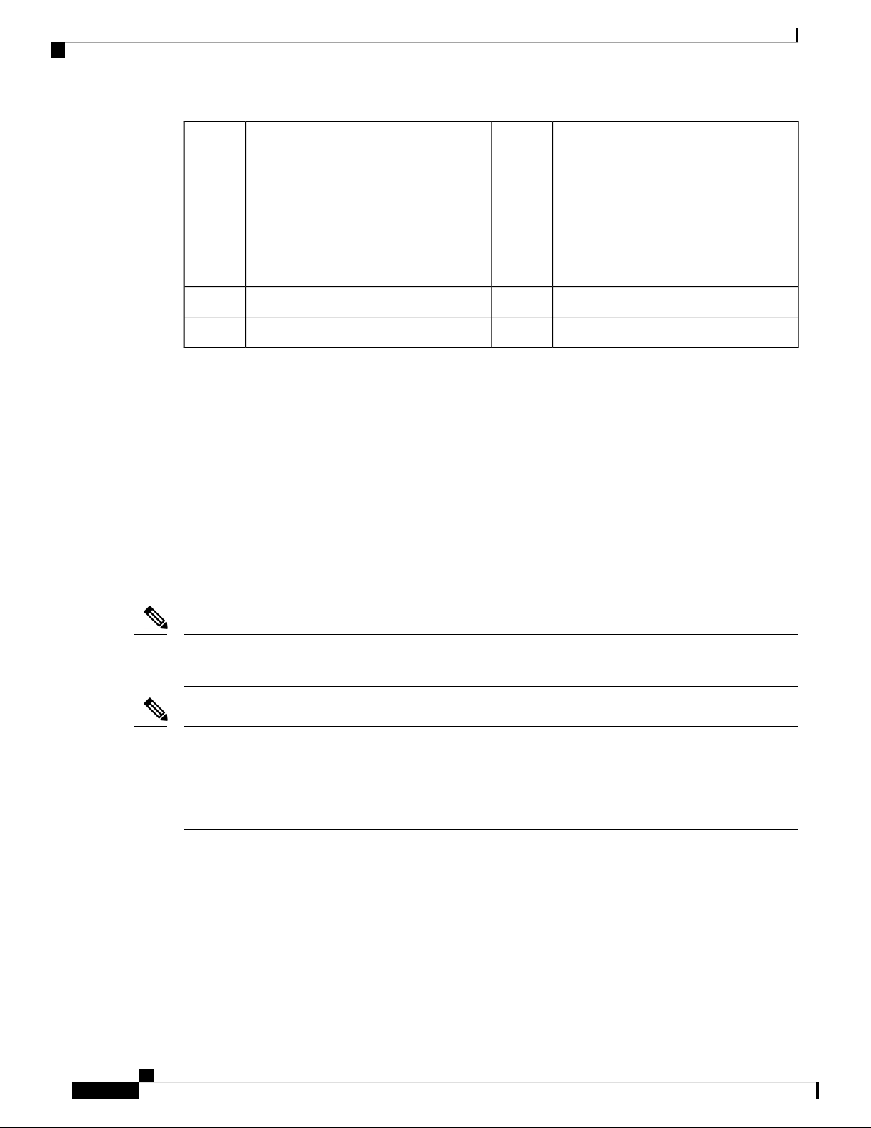
The following table lists the features for the Firepower 4100 series.
Table 1: Firepower 4100 Series Features
4150414041204110Feature
Form factor
1 RU
Fits a standard 19-in. (48.3cm) square-hole rack
Rack mount
Yes
Slide rails, mount ears, and screws included (4-post EIA-310-D rack)
Airflow
Front to rear
Cold aisle to hot aisle
Single 22-coreSingle 18-core
256-GB DDR4
DRAM
Memory
Maximum number
of interfaces
Single 12-coreProcessor
64-GB DDR4
DRAM
128-GB DDR4
DRAM
24
With two 8-port network modules installed
256-GB DDR4
DRAM
Management port
One Gigabit Ethernet
Supports 1-G fiber or copper SFPs
Cisco Firepower 4110, 4120, 4140, and 4150 Hardware Installation Guide
2
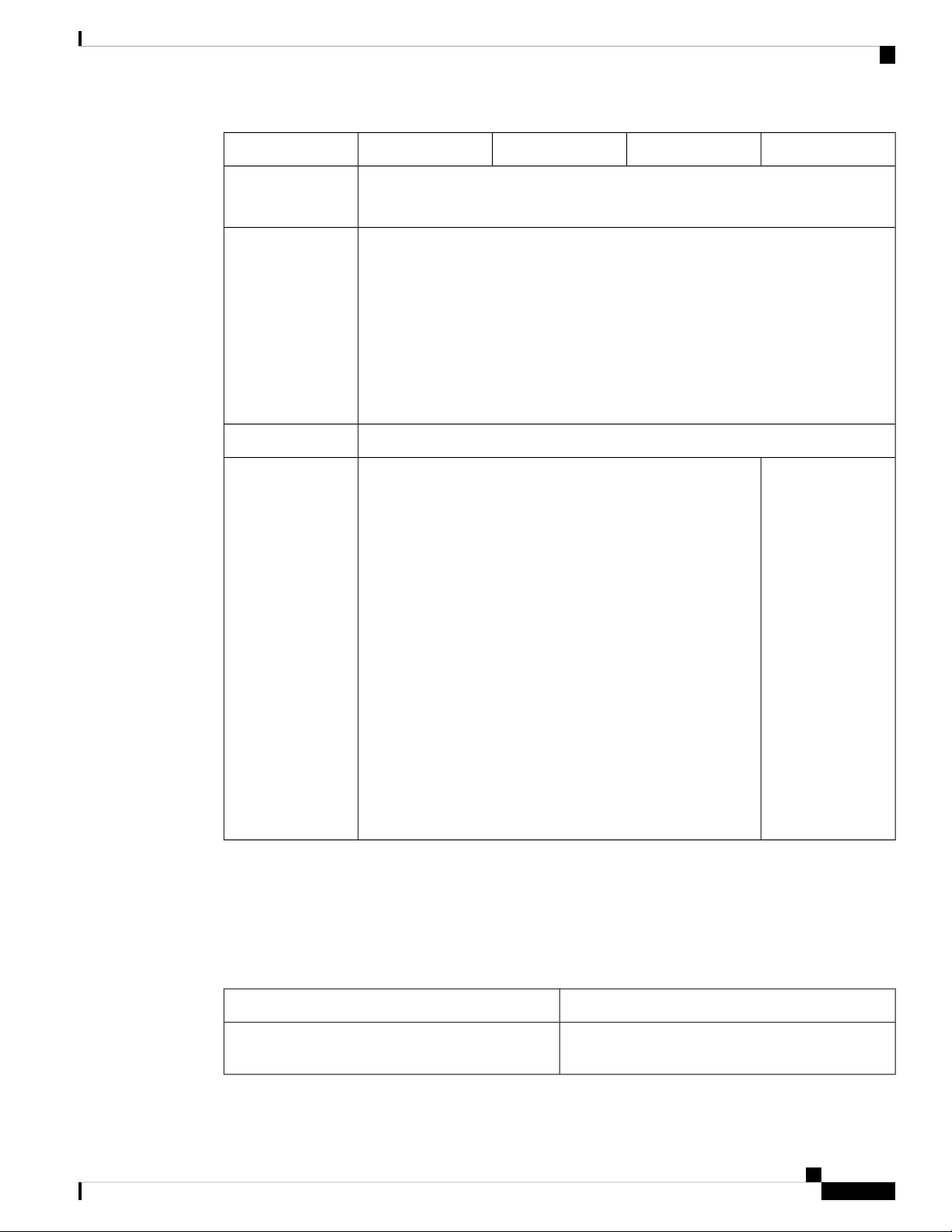
Page 7

Overview
Features
4150414041204110Feature
One RJ-45 consoleSerial port
One USB 2.0 Type AUSB port
Eight fixed 1-G and 10-G SFP ports (named Ethernet 1/1 through 1/8)Network ports
SFP ports
Pullout asset card
Grounding lug
Locator beacon
Power switch
Network modules
Supported network
modules
Yes
Eight fixed 1-G and 10-G SFP ports
See Network Modules, on page 10 for the number of SFP/SFP+ ports for each network
module.
Yes
Displays the serial number; on the front panel
Yes
On rear panel
Yes
On front panel
Yes
On rear panel
Yes
Two network module slots ( named network module 2 and network module 3)
8-port 10-Gigabit Ethernet SFP+
4-port 40-Gigabit Ethernet QSFP+
AC power supply
8-port 1-Gigabit Ethernet SFP+ fail-to-wire
2-port 40-Gigabit Ethernet SFP+ fail-to-wire
6-port 1-Gigabit Ethernet SX fiber fail-to-wire
6-port 10-Gigabit Ethernet SR fiber fail-to-wire
6-port 10-Gigabit Ethernet LR fiber fail-to-wire
Two (1+1) power supply module slots
Ships with one 400-W AC power supply
modules
Hot-swappable
Two (1+1) power supply module slots
Ships with two 400-W AC power supply
modules
Hot-swappable
Yes (optional)NoDC power supply
Yes 1+1Redundant power
Cisco Firepower 4110, 4120, 4140, and 4150 Hardware Installation Guide
3
Page 8

Deployment Options
Overview
4150414041204110Feature
Fan
Storage
MSP
Deployment Options
Here are some examples of how you can deploy the Firepower 4100:
• In a data center using NGFW and ASA
• At the core/aggregation layer of a 3-tier data center in a high availability configuration
Six fan module slots
3+1 redundancy
Hot-swappable
Two SSD slots (200 GB)
Ships with one SSD installed in slot 1.
Note
Slot 2 is reserved for the Malware Storage
Pack (MSP).
Yes
Installed in the second SSD slot only
RAID is not supported.
Two SSD slots (400 GB)
Ships with one SSD installed in slot 1.
Note
Slot 2 is reserved for the MSP.
RAID is not supported.
• As a dedicated multifunctional security service within converged infrastructure stacks, for example,
vBlock, FlexPod, and so forth, at the access layer
• As a high-performance data center security appliance between the WAN edge and the data center core
in a high availability configuration
• Inter-DC clustering deployments
• In newer spine/leaf data center designs, deployment as a leaf that exclusively offers security functions
Package Contents
The following figure shows the package contents for the Firepower 4100. Note that the contents are subject
to change and your exact contents might contain additional or fewer items.
Cisco Firepower 4110, 4120, 4140, and 4150 Hardware Installation Guide
4
Page 9

Overview
Serial Number Location
Figure 2: Firepower 4100 Package Contents
9
inner slide rail to the chassis
Welcome to the Cisco Firepower 410015
Serial Number Location
The serial number for the Firepower 4100 series chassis is located on the pullout asset card on the front panel.
Blue console cable PC terminal adapter2Firepower 4100 chassis1
10/100/1000BASE-T SFP transceiver42 power cords (country-specific)3
Tie wrap clamp62 slide rails5
Flextronics tie wrap8Artesyn tie wrap7
102 M3X6 mm screws used to secure the
122 slide rail locking brackets11
Ten 8-32 x .375-in. countersink screws
used to secure the mounting bracket to
chassis (6 screws), and the cable
management brackets to the mounting
brackets (4 screws)
Two 10-32 x .375-in. screws used to secure
the ground lug
2 cable management brackets141 ground lug #6 AWG, 90 degree, #10 post13
Cisco Firepower 4110, 4120, 4140, and 4150 Hardware Installation Guide
5
Page 10

Front Panel
Overview
Figure 3: Serial Number on the 4100 Chassis
You can also view additional model information on the compliance label located on the bottom of the chassis.
Figure 4: Compliance Label on the 4100 Chassis
Front Panel
Cisco Firepower 4110, 4120, 4140, and 4150 Hardware Installation Guide
6
The following figure shows the front panel of the Firepower 4100.
Page 11

Overview
Front Panel LEDs
Figure 5: Firepower 4100 Front Panel
Gigabit Ethernet management port2RJ-45 console port1
11
Front Panel LEDs
The following figure and table describe the Firepower 4100 front panel LEDs.
Figure 6: Front Panel LEDs
Network module 3
Note
The 10-G network module is
shown.
4USB Type A port3
Eight fixed SFP+ (1-G/10-G) ports (in
network module slot 1)
Gigabit Ethernet 1/1 through 1/8 labeled
top to bottom, left to right
SSD 26SSD 15
Locator LED8Power LED7
10Pullout asset card9
Network module 2
Note
The 10-G network module is
shown.
Cisco Firepower 4110, 4120, 4140, and 4150 Hardware Installation Guide
7
Page 12

Rear Panel
Overview
1
• Off—No connection or port is not in
use.
• Amber—No link or network failure.
• Green—Link up.
• Green, flashing—Network activity.
3
• Off— SSD not present.
• Green—SSD is present; no activity.
• Green, flashing—SSD is active.
• Amber—SSD failure.
• Amber, flashing—Rebuilding, flashes
at 1 Hz.
• Amber, flashing—Predictive failure
analysis (PFA) and hot spare; two fast
flashes at 4 Hz, pause for 0.5 seconds.
2Management
4SSD
Health (SYS)
• Off—System is not booting yet.
• Green, flashing—Power-up
diagnostics are complete and system
is booting up.
• Green—The system has passed
power-up diagnostics.
• Amber—Power-up diagnostics has
failed.
• Amber, flashing—Alarm; power-up
diagnostics are running.
Power
• Off—Input power not detected.
• Green, flashing—Appears only when
you move the power switch from ON
to OFF. System is shutting down and
powers off once shutdown is
completed.
• Amber—System is powering up.
• Green—System fully powered up.
• Amber, flashing—Reserved.
Rear Panel
5
This LED is not supported; reserved for
future use.
7
The following figure shows the rear panel of the Firepower 4100.
Network activity
• Off—No connection or port is not in
use.
• Amber—No link or network failure.
• Green—Link up.
• Green, flashing—Network activity.
6Active (ACT)
Locator LED
• Off—Locate is off.
• Blue—Locate is on.
Cisco Firepower 4110, 4120, 4140, and 4150 Hardware Installation Guide
8
Page 13

Overview
Rear Panel
Figure 7: Firepower 4100 Rear Panel
Power supply module 12Power on/off switch1
Fan module 14Power supply module 23
Fan module 36Fan module 25
Fan module 58Fan module 47
10Fan module 69
Location for the two-post grounding lug
Note
The two-post grounding lug is
included in the accessory kit.
The power switch is located to the left of power supply module 1 on the rear of the chassis. It is a toggle
switch that controls power to the system. If the power switch is in standby position, only the 3.3-V standby
power is enabled from the power supply module and the 12-V main power is OFF. When the switch is in the
ON position, the 12-V main power is turned on and the system boots.
You can shut down the chassis in one of two ways:
• Perform a graceful shutdown using the shutdown commands. This may take several minutes to complete.
Then toggle the power switch to the OFF position. The power LED changes from solid green to off
immediately.
Note
The shutdown commands are first available in FXOS version 2.0.1. See the
FXOS Configuration Guide for more information on using these commands.
Caution
If you move the power switch to the OFF position before the shutdown command
sequence is complete or if you remove the system power cords before the graceful
shutdown is complete, disk corruption can occur.
• Toggle the power switch to the OFF position. The power LED changes from solid green to off.
Note
After removing power from the chassis either by moving the power switch to OFF or unplugging the power
cord, wait at least 10 seconds before turning power back ON.
Cisco Firepower 4110, 4120, 4140, and 4150 Hardware Installation Guide
9
Page 14
Network Modules
Network Modules
The Firepower 4100 contains two network module slots that provide optical or electrical network interfaces.
Network modules are optional, removable I/O modules that provide either additional ports or different interface
types (1/10/40 G). The Firepower network modules plug into the chassis on the front panel.
For More Information
• See 10-G Network Module , on page 10 for a description of the 10-G network module.
• See 40-G Network Module , on page 11 for a description of the 40-G network module.
• See Hardware Bypass Network Modules, on page 12 for the location and description of the LEDs,
and the port configurations for the hardware bypass network modules.
• See Remove and Replace the Network Module, on page 55 for the procedure for removing and
replacing network modules.
Overview
10-G Network Module
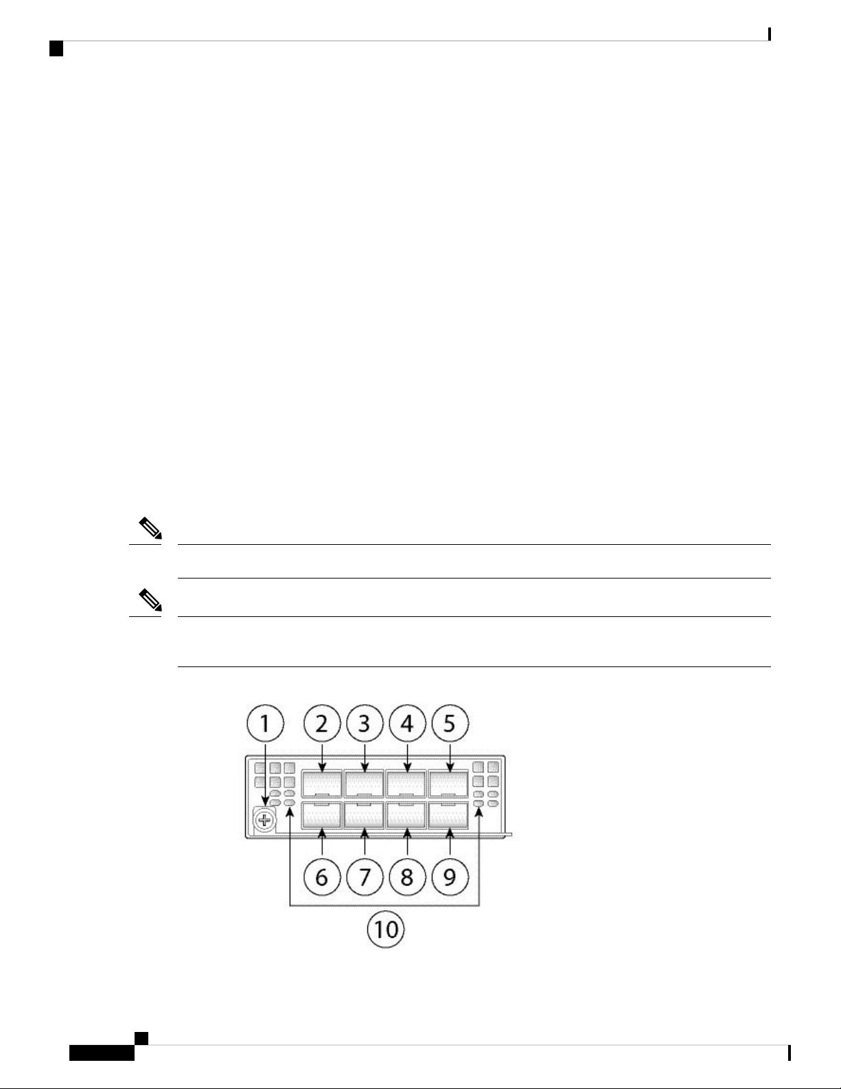
The following figure shows the front panel of the 10-G network module (FPR4K-NM-8X10G). The
FPR4K-NM-8X10G is a single-wide module that supports hot swapping. The eight ports are numbered from
top to bottom, left to right.
Note
The FPR4K-NM-8X10G is NEBS-compliant.
Note
You can fit four copper SFPs in either the top row of ports or the bottom row of ports. Both rows cannot be
populated at the same time, because of the port row spacing.
Figure 8: FPR4K-NM-8X10G
Cisco Firepower 4110, 4120, 4140, and 4150 Hardware Installation Guide
10
Page 15

Overview
40-G Network Module
3
5
7
9
Ethernet X/3
Ethernet X/7
Ethernet X/4
Ethernet X/8
For More Information
• For a list of copper SFPs, see Supported SFP/SFP+ and QSFP Transceivers, on page 21.
40-G Network Module
The following figure shows the front panel of the 40-G network module (FPR4K-NM-4X40G.) The
FPR4K-NM-4X40G is a single-wide module that supports hot swapping. The four ports are numbered left to
right.
2Captive screw/handle1
4
6
8
10
Ethernet X/1
Ethernet X/5
Ethernet X/2
Ethernet X/6
Network activity LEDs
• Off—No connection or port is not in
use.
• Amber—No link or network failure.
• Green—Link up.
• Green, flashing—Network activity.
Note
The FPR4K-NM-4X40G is NEBS-compliant.
Figure 9: FPR4K-NM-4X40G
Cisco Firepower 4110, 4120, 4140, and 4150 Hardware Installation Guide
11
Page 16
Hardware Bypass Network Modules
Overview
3
5
Ethernet X/1
Ethernet X/3
Hardware Bypass Network Modules
Fail-to-wire (also known as hardware bypass) is a physical layer (Layer 1) bypass that allows paired interfaces
to go into bypass mode so that the hardware forwards packets between these port pairs without software
intervention. Fail-to-wire provides network connectivity when there are software or hardware failures. Hardware
bypass is useful on ports where the Firepower security appliance is only monitoring or logging traffic. The
hardware bypass network modules have an optical switch that is capable of connecting the two ports when
needed.
The fail-to-wire network modules have built-in SFPs.
2Captive screw/handle1
4
6
Network activity LEDs
• Off—No connection or port is not in
use.
• Amber—No link or network failure.
• Green—Link up.
• Green, flashing—Network activity.
Ethernet X/2
Ethernet X/4
Hardware bypass is supported only on a fixed set of ports. You can pair Port 1 with Port 2, Port 3 with Port
4, but you cannot pair Port 1 with Port 4 for example.
Note
Hardware bypass is only supported in inline mode. Also, hardware bypass support depends on your software
application.
Note
When the appliance switches from normal operation to hardware bypass or from hardware bypass back to
normal operation, traffic may be interrupted for several seconds. A number of factors can affect the length of
the interruption; for example, behavior of the optical link partner such as how it handles link faults and
debounce timing; spanning tree protocol convergence; dynamic routing protocol convergence; and so on.
During this time, you may experience dropped connections.
There are three configuration options for hardware bypass network modules:
• Passive interfaces—Connection to a single port.
For each network segment you want to monitor passively, connect the cables to one interface. This is
how the non-fail-to-wire network modules operate.
• Inline interfaces—Connection to any two like ports (10 G to 10 G for example) on one network module,
across network modules, or fixed ports.
For each network segment you want to monitor inline, connect the cables to pairs of interfaces.
Cisco Firepower 4110, 4120, 4140, and 4150 Hardware Installation Guide
12
Page 17

Overview
1-G Network Module with Hardware Bypass
• Inline with fail-to-wire interfaces—Connection of a fail-to-wire paired set.
For each network segment that you want to configure inline with fail-open, connect the cables to the
paired interface set.
For the 40-G network module, you connect the two ports to form a paired set. For the 1/10-G network
modules, you connect the top port to the bottom port to form a fail-to-wire paired set. This allows traffic
to flow even if the security appliance fails or loses power.
Note
If you have a inline interface set with a mix of fail-to-wire and non-fail-to-wire interfaces, you cannot enable
hardware bypass on this inline interface set. You can only enable hardware bypass on an inline interface set
if all the pairs in the inline set are valid fail-to-wire pairs.
For More Information
• See 1-G Network Module with Hardware Bypass, on page 13 for a description of the 1-G network
module.
• See 40-G Network Module with Hardware Bypass, on page 14 for a description of the 40-G network
module.
• See 1-G SX/10-G SR/10-G LR Network Module with Hardware Bypass, on page 16 for a description
of the 1-G SX, 10-G SR, and LR network modules.
• See Remove and Replace the Network Module, on page 55 for the procedure for removing and
replacing single-wide network modules.
1-G Network Module with Hardware Bypass
The following figure shows the front panel view of the 1-G fail-to-wire network module (FPR4K-NM-8X1G-F).
Pair ports 1 and 2, 3 and 4, 5 and 6, and 7 and 8 to form hardware bypass paired sets.
Figure 10: FPR-NM-8X1G-F
Cisco Firepower 4110, 4120, 4140, and 4150 Hardware Installation Guide
13
Page 18

40-G Network Module with Hardware Bypass
Overview
2Captive screw/handle1
8 network activity LEDs
• Left LED—Green indicates network
activity when a 10M/100M/1G
connection is made.
• Right LED—Not in use at this time.
3
Ethernet X/1
Ports 1 and 2 are paired together to form
a hardware bypass pair. LED B1 applies
to this paired port.
5
Ethernet X/2
Ports 5 and 6 are paired together to form
a hardware bypass pair. LED B3 applies
to this paired port.
4
Ethernet X/2
Ports 3 and 4 are paired together to form a
hardware bypass pair. LED B2 applies to
this paired port.
6
Ethernet X/2
Ports 7 and 8 are paired together to form a
hardware bypass pair. LED B4 applies to
this paired port.
Bypass LEDs B1 through B4
• Green—In standby mode.
• Amber, flashing—Port is in hardware
bypass mode, failure event.
• Amber—Port is in hardware bypass
mode, forced.
40-G Network Module with Hardware Bypass
The following figure shows the front panel of the 40-G fail-to-wire network module (FPR4K-NM-2X40G-F).
The FPR4K-NM-2X40G-F is a single-wide module that does not support hot swapping. The two ports are
numbered left to right. Pair the two ports to create a hardware bypass paired set.
Figure 11: FPR4K-NM-2X40G-F
Cisco Firepower 4110, 4120, 4140, and 4150 Hardware Installation Guide
14
Page 19

Overview
40-G Network Module with Hardware Bypass
2Captive screw/handle1
Ethernet X/1
Ports 1 and 2 are paired together to form
a hardware bypass pair.
3
• Green—In standby mode.
• Amber, flashing—Port is in hardware
4Bypass LED BP:
Ethernet X/2
Ports 1 and 2 are paired together to form
a hardware bypass pair.
bypass mode, failure event.
• Amber—Port is in hardware bypass
mode, forced.
5
Network activity LEDs:
• Amber—No connection, or port is
not in use, or no link or network
failure.
• Green—Link up, no network activity.
• Green, flashing—Network activity.
The following table describes the cable specifications needed to keep the insertion loss as low as possible.
Table 2: 40-G BASE-SR Cable Specifications
Supported CableInterface
50 microns core diameterEthernet 40-G BASE-SR4
2000/4700 (OM3/4) modal bandwidth (MHz*km)850 nm wavelength
50 m cable distanceMPO-12 port adapter
Note
See the Cisco 40GBASE QSFP Modules Data Sheet for specifications of the QSFP for the 40-G BASE-SR-4.
We recommend the following Cisco OM3 MTP/MPO cables.
Table 3: Cisco Cables
Cable LengthCisco Part Number
5 mCAB-ETH-40G-5M
10 mCAB-ETH-40G-10M
20 mCAB-ETH-40G-20M
Cisco Firepower 4110, 4120, 4140, and 4150 Hardware Installation Guide
15
Page 20

1-G SX/10-G SR/10-G LR Network Module with Hardware Bypass
1-G SX/10-G SR/10-G LR Network Module with Hardware Bypass
The following figure shows the front panel of the 1-G SX, 10-G SR and 10-G LR fail-to-wire network modules
(FPRK4-NM-6X1SX-F, FPRK4-NM-6X10SR-F, FPR4K-NM-6X10LR-F). This is a single-wide module that
does not support hot swapping. The six ports are numbered from top to bottom, left to right. Pair ports 1 and
2, 3 and 4, and 5 and 6 to form hardware bypass paired sets.
Figure 12: FPR4K-NM-6X1SX-F, FPR4K-NM-6X10SR-F, FPR4K-NM-6X10LR-F
Overview
2Captive screw/handle1
6 network activity LEDs
• Amber—No connection, or port is not
in use, or no link or network failure.
• Green—Link up, no network activity.
• Green, flashing—Network activity.
3
• Green—In standby mode.
• Amber, flashing—Port is in hardware
bypass mode, failure event.
4Bypass LEDs B1 through B3:
Ethernet X/1 (top port)
Ethernet X/2 (bottom port)
Ports 1 and 2 are paired together to form a
hardware bypass pair.
• Amber—Port is in hardware bypass
mode, forced.
5
Ethernet X/3 (top port)
Ethernet X/4 (bottom port)
Ports 3 and 4 are paired together to form
a hardware bypass pair.
6
Ethernet X/5 (top port)
Ethernet X/6 (bottom port)
Ports 5 and 6 are paired together to form a
hardware bypass pair.
The 1-G SX /10-G SR/10-G LR network modules have the following insertion loss measurements. Insertion
loss measurements help you to troubleshoot the network by verifying cable installation and performance.
Table 4: 1-G SX Network Module (FPR4K-NM-6X1SX-F)
MaximumTypicalOperating Mode
Cisco Firepower 4110, 4120, 4140, and 4150 Hardware Installation Guide
16
Page 21

Overview
1-G SX/10-G SR/10-G LR Network Module with Hardware Bypass
Insertion loss
Normal
Hardware bypass
Core diameter (microns)
Cable and operating
distance
62.5
62.5
50
50
50
Table 5: 10-G SR Network Module (FPR4K-NM-6X10SR-F)
Insertion loss
Normal
0.9 dB
1.2 dB
Modal bandwidth
(MHz/km)
160 (FDDI)
200 (OM1)
400
500 (OM2)
2000 (OM3)
0.9 dB
1.4 dB
1.7 dB
Cable distance
Note
Half the
distance
specified by
the IEEE
standard.
110 m
137 m
250 m
275 m
500 m
MaximumTypicalOperating Mode
1.4 dB
Hardware bypass
Core diameter (microns)
Cable and operating
distance
62.5
62.5
50
50
50
50
Table 6: 10-G LR Network Module (FPR4K-NM-6X10LR-F)
Insertion loss
Normal
1.2 dB
Modal bandwidth
(MHz/km
160 (FDDI)
200 (OM1)
400
500 (OM2)
2000 (OM3)
4700 (OM4)
1.2 dB
1.7 dB
Cable distance
Note
Half the
distance
specified by
the IEEE
standard.
13 m
16.5 m
33 m
41 m
150 m
200 m
MaximumTypicalOperating Mode
1.6 dB
Hardware bypass
Cisco Firepower 4110, 4120, 4140, and 4150 Hardware Installation Guide
1.5 dB
1.9 dB
17
Page 22

Power Supply Modules
Overview
distance
Power Supply Modules
The Firepower 4100 supports two AC or DC power supply modules so that dual power supply redundancy
protection is available. Facing the back of the chassis, the power supply modules are numbered left to right,
for example, PSU1 and PSU2.
Note
Do not mix AC and DC power supply modules in one chassis.
Core diameter (microns)
Modal bandwidth
(MHz/km
Cable distance
Note
Half the
distance
specified by
the IEEE
standard.
5 kmSingle modeG.652Cable and operating
Note
Attention
After removing power from the chassis either by moving the power switch to OFF or unplugging the power
cord, wait at least 10 seconds before turning power back ON.
Make sure that one power supply module is always active.
See Remove and Replace the Power Supply Module, on page 61 for the procedure for removing and replacing
the power supply module.
AC Power Supply
The power supplies can supply up to 1100-W power across the input voltage range. The load is shared when
both power supply modules are plugged in and running at the same time. The power supply modules are
hot-swappable.
Table 7: AC Power Supply Module Hardware Specifications
100 to 240 V ACInput voltage
Maximum current
13 A (at 100 V AC)
Note
The system power requirements are lower than the power
supply module capabilities. See Hardware Specifications, on
page 23 for the system power requirements.
1100 WMaximum output power
Cisco Firepower 4110, 4120, 4140, and 4150 Hardware Installation Guide
18
Page 23

Overview
Power Supply Modules
50 to 60 HzFrequency
1+1 redundantRedundancy
92%Efficiency at 50% load
DC Power Supply
The power supplies can supply up to 950 W of power across the input voltage range. The load is shared when
both power supply modules are plugged in and running at the same time. The power supply modules are
hot-swappable.
Table 8: DC Power Supply Module Hardware Specifications
-40 to -60 V DCInput voltage
Maximum current
26A (at 40 V DC)
Note
The system power requirements are lower than the power
supply module capabilities. See Hardware Specifications, on
page 23 for the system power requirements.
950 WMaximum output power
1+1 redundantRedundancy
92%Efficiency at 50% load
Power Supply Module LEDs
The following figure shows the two-color power supply LEDs. The LEDs are located on the upper right side.
Figure 13: Power Supply Module LEDs
The following table describes the power module supply LEDs.
Cisco Firepower 4110, 4120, 4140, and 4150 Hardware Installation Guide
Green OK LED2Amber FAIL LED1
19
Page 24

Fan Modules
Overview
Table 9: Power Supply Module LEDs
Green LED (OK Status)Amber LED (Fail
Status)
OffOffNo power to all power supplies
OffOnPower supply module failure
Includes over voltage, over current, over temperature,
and fan failure
Off1 Hz flashingPower supply module warning events
Power supply continues to operate (high temperature,
high power, and slow fan)
1 Hz flashingOffPower is present.
3.3 VSB on (power supply module off)
OnOffPower supply module is OK and on.
Fan Modules
The Firepower 4100 requires six fan modules, which are hot-swappable. They are installed in the rear of the
chassis. The system supports operation with a single fan failure (N+1 fan redundancy), but do not run the
system for an extended amount of time without all fan modules installed. Keep removal and replacement time
at 3 minutes. Remove and replace one fan module at a time.
If you remove a fan or a fan fails, the other fans operate at full speed, which can be noisy.
The fan modules are numbered left to right, for example, FAN1, FAN2, FAN3, FAN4, FAN5, and FAN6.
See Remove and Replace the Fan Module, on page 58 for the procedure for removing and replacing the fan
module.
The following figure shows the location of the fan LED.
Figure 14: Fan LED
Cisco Firepower 4110, 4120, 4140, and 4150 Hardware Installation Guide
20
Page 25

Overview
Supported SFP/SFP+ and QSFP Transceivers
Two-color LED1
The fan module has one two-color LED, which is located on the upper left corner of the fan.
• Amber—Fan failure.
• Green—Fan running normally. It may take up to 1 minute for the LED status to turn green after power
is on.
Supported SFP/SFP+ and QSFP Transceivers
The SFP/SFP+ transceivers are bidirectional devices with a transmitter and receiver in the same physical
package. It is a hot-swappable optical or electrical (copper) interface that plugs into the SFP/SFP+ ports on
the fixed ports and the network module ports, and provides Ethernet connectivity.
Warning
Caution
Use appropriate ESD procedures when inserting the transceiver. Avoid touching the contacts at the rear, and
keep the contacts and ports free of dust and dirt. Keep unused transceivers in the ESD packing that they were
shipped in. The following figure shows a sample SFP transceiver.
Figure 15: SFP
Bail clasp2Dust plug1
Transmit optical bore4Receive optical bore3
Although non-Cisco SFPs are allowed, we do not recommend using them because they have not been tested
and validated by Cisco. Cisco TAC may refuse support for any interoperability problems that result from
using an untested third-party SFP transceiver.
Caution
For some earlier production Firepower 4100 series chassis, you may experience difficulty using the GLC-TE
SFP on the management port or fixed ports. Contact Cisco TAC for support if you encounter problems with
the GLC-TE SFP.
Cisco Firepower 4110, 4120, 4140, and 4150 Hardware Installation Guide
21
Page 26

Supported SFP/SFP+ and QSFP Transceivers
The following table lists the Cisco supported transceivers.
Table 10: Supported Cisco SFP/SFP+ Transceivers
1 G
10 G
Overview
PIDOptics Type
GLC-SX-MMD1G-SX
GLC-LH-SMD1G-LH/LX
GLC-EX-SMD1G-EX
GLC-ZX-SMD1G-ZX
GLC-T1G 1000Base-T
GLC-TE1G 1000Base-T
SFP-10G-SR10G-SR
SFP-10G-SR-S10G-SR-S
SFP-10G-LR10G-LR
SFP-10G-LR-S10G-LR-S
SFP-10G-LRM10G-LRM
SFP-10G-ER10G-ER
SFP-10G-ER-S10G-ER-S
SFP-10G-ZR-S10G-ZR-S
SFP-H10GB-CU1M10G Cu, 1m
SFP-H10GB-CU1-5M10G Cu, 1.5m
SFP-H10GB-CU2M10G Cu, 2m
SFP-H10GB-CU2-5M10G Cu, 2.5m
SFP-H10GB-CU3M10G Cu, 3m
SFP-H10GB-CU5M10G Cu, 5m
SFP-H10GB-ACU7M10G Cu, 7m
SFP-H10GB-ACU10M10G Cu, 10m
SFP-10G-AOC1M10G AOC, 1m
SFP-10G-AOC2M10G AOC, 2m
Cisco Firepower 4110, 4120, 4140, and 4150 Hardware Installation Guide
22
Page 27

Overview
Hardware Specifications
SFP-10G-AOC3M10G AOC, 3m
SFP-10G-AOC5M10G AOC, 5m
SFP-10G-AOC7M10G AOC, 7m
SFP-10GAOC10M10G AOC, 10m
40 G
QSFP-40G-SR440G-SR4
QSFP-40G-SR4-S40G-SR4-S
QSFP-40G-CSR440G-CSR4
QSFP-40G-SR-BD40G-SR-BD
QSFP-40GE-LR440GE-LR4
QSFP-40GE-LR4-S40GE-LR4-S
Hardware Specifications
The following table contains hardware specifications for the Firepower 4100.
Table 11: Firepower 4100 Hardware Specifications
Physical
Form factor
1 RU
Fits standard 19-in. (48.3-cm) square-hole rack
WSP-Q40GLR4L40G-LR4L
QSFP-H40G-CU40G-CU, 1M, 3M, 5M
QSFP-4SFP10G-CU40G-4X10G-CU, 1M, 3M, 5M
QSFP-H40G-ACU40G-CU-A, 7M, 10M
QSFP-4X10G-AC40G-4X10G-CU-A, 7M, 10M
QSFP-H40G-AOC40G-AOC, 1M, 2M, 3M, 5M, 7M, 10M, 15M
4150414041204110Specification
Rack mount
x D)
Yes, mount rails included
4-post EIA-310-D rack
1.75 x 16.89 x 29.7 in. (4.44 x 42.90 x 75.43 cm)Dimensions (H x W
Cisco Firepower 4110, 4120, 4140, and 4150 Hardware Installation Guide
23
Page 28

Hardware Specifications
Overview
4150414041204110Specification
Weight
Storage
SSD
MSP
Memory
36 lb (16kg) 2 power supply modules, 2 network modules, 6 fans
30 lb (13.6 kg) no power supply modules, no network modules, no fans
100 GB
Note
Note
The storage SSD must be
installed in slot 1. Slot 2 is
reserved for the MSP SSD.
If you are running Firepower
Threat Defense software, we
recommend that you upgrade to
the latest version (at least to
Version 6.1.0) to take
advantage of software updates
that enhance SSD management
performance and longevity.
200 GB
Note
Note
The storage SSD must be
installed in slot 1. Slot 2 is
reserved for the MSP SSD.
If you are running Firepower
Threat Defense software, we
recommend that you upgrade to
the latest version (at least to
Version 6.1.0) to take
advantage of software updates
that enhance SSD management
performance and longevity.
800 GB
Note
The MSP SSD must be installed in slot 2,
DDR4 DIMM
Power
System power
module
Environment
Temperature
256 GB128 GB64 GB
AC: 100/240 V AC 10 A (at 100 V), 50 to 60 Hz
DC: -40 V DC to -60 V DC, 26 A (at -40 V)
AC or DCPower supply
YesRedundant power
Operating: 32° to 104° F (0° to 40° C)
Nonoperating: -40° to 149°F (-40° to 65°
C)
Operating: 32° to 95° F (0° to 35° C) at
sea level
1° C reduction of maximum for every 1000
ft (305 m) above sea level
Nonoperating: -40° to 149° F (-40° to 65°
C)
Operating and nonoperating: 5 to 95 % noncondensingHumidity
Cisco Firepower 4110, 4120, 4140, and 4150 Hardware Installation Guide
24
Page 29
Overview
Product ID Numbers
4150414041204110Specification
Altitude
Acoustic noise
Operating: 10,000 ft maximum (3048 m)
Nonoperating: 40,000 ft maximum (12,192 m)
Sound pressure:
• 61 dBA (typical)
• 78 dBA (maximum)
Sound power:
• 72 dBA (typical)
• 88 dBA (maximum)
Front to backAir flow
—NEBS operation
Operating
temperature:
• Long term: 0°
to 45° C up to
6000 ft (1829
m)
• Long term: 0°
to 35° C up to
6000-13,000 ft
(1829-3964 m)
Product ID Numbers
The following table lists all of the PIDs associated with the Firepower 4100 series.
Table 12: Firepower 4100 Series PIDs
FPR4110-AMP-K9
• Short term: -5°
to 55° C up to
6000 ft (1829
m)
Operating altitude:
0 to 13,000 ft (3962
m)
DescriptionPID
Cisco Firepower 4110 AMP appliance, 1 RU, two
network module bays
Cisco Firepower 4110, 4120, 4140, and 4150 Hardware Installation Guide
25
Page 30

Product ID Numbers
Overview
DescriptionPID
FPR4110-ASA-K9
FPR4110-NGFW-K9
FPR4110-NGIPS-K9
FPR4120-AMP-K9
FPR4120-ASA-K9
FPR4120-NGFW-K9
FPR4120-NGIPS-K9
FPR4140-AMP-K9
FPR4140-ASA-K9
Cisco Firepower 4110 ASA appliance, 1 RU, two
network module bays
Cisco Firepower 4110 NGFW appliance, 1 RU, two
network module bays
Cisco Firepower 4110 NGIPS appliance, 1 RU, two
network module bays
Cisco Firepower 4120 AMP appliance, 1 RU, two
network module bays
Cisco Firepower 4120 ASA appliance, 1 RU, two
network module bays
Cisco Firepower 4120 NGFW appliance, 1 RU, two
network module bays
Cisco Firepower 4120 NGIPS appliance, 1 RU, two
network module bays
Cisco Firepower 4140 AMP appliance, 1 RU, two
network module bays
Cisco Firepower 4140 ASA appliance, 1 RU, two
network module bays
FPR4140-NGFW-K9
FPR4140-NGIPS-K9
FPR4150-AMP-K9
FPR4150-ASA-K9
FPR4150-NGFW-K9
FPR4150-NGIPS-K9
FPR4K-ACC-KIT
FPR4K-ACC-KIT=
FPR4K-ASA-CAR
Cisco Firepower 4140 NGFW appliance, 1 RU, two
network module bays
Cisco Firepower 4140 NGIPS appliance, 1 RU, two
network module bays
Cisco Firepower 4150 AMP appliance, 1 RU, two
network module bays
Cisco Firepower 4150 ASA appliance, 1 RU, two
network module bays
Cisco Firepower 4150 NGFW appliance, 1 RU, two
network module bays
Cisco Firepower 4150 NGIPS appliance, 1 RU, two
network module bays
Firepower hardware accessory kit containing rack
mounts and cables
Firepower hardware accessory kit containing rack
mounts and cables (spare)
License to add carrier security to ASA on the
Firepower 4100
Cisco Firepower 4110, 4120, 4140, and 4150 Hardware Installation Guide
26
Page 31

Overview
Product ID Numbers
DescriptionPID
FanFPR4K-FAN
Fan (spare)FPR4K-FAN=
2-port 40-G SR fail-to-wire network moduleFPR4K-NM-2X40G-F
2-port 40-G SR fail-to-wire network module (spare)FPR4K-NM-2X40G-F=
4-port QSFP+ network moduleFPR4K-NM-4X40G
4-port QSFP+ network module (spare)FPR4K-NM-4X40G=
6-port 10-G LR fail-to-wire network moduleFPR4K-NM-6X10LR-F
6-port 10-G LR fail-to-wire network module (spare)FPR4K-NM-6X10LR-F=
6-port 10-G SR fail-to-wire network moduleFPR4K-NM-6X10SR-F
6-port 10-G SR fail-to-wire network module (spare)FPR4K-NM-6X10SR-F=
FPR4K-NM-6X1SX-F=
6-port 1-G SX fiber fail-to-wire network moduleFPR4K-NM-6X1SX-F
6-port 1-G SX fiber fail-to-wire network module
(spare)
8-port SFP+ network moduleFPR4K-NM-8X10G
8-port SFP+ network module (spare)FPR4K-NM-8X10G=
8-port 1-G copper fail-to-wire network moduleFPR4K-NM-8X1G-F
8-port 1-G copper fail-to-wire network module (spare)FPR4K-NM-8X1G-F=
Network module blank slot coverFPR4K-NM-BLANK
Network module blank slot cover (spare)FPR4K-NM-BLANK=
Chassis power supply module blank slot coverFPR4K-PSU-BLANK
Chassis power supply module blank slot cover (spare)FPR4K-PSU-BLANK=
1100W AC power supply moduleFPR4K-PWR-AC-1100
1100W AC power supply module (spare)FPR4K-PWR-AC-1100-
950W DC power supply moduleFPR4K-PWR-DC-950
950W DC power supply module (spare)FPR4K-PWR-DC-950=
Rack mount kitFPR4K-RACK-MNT
Rack mount kit (spare)FPR4K-RACK-MNT=
SSD slot carrierFPR4K-SSD-BBLKD
Cisco Firepower 4110, 4120, 4140, and 4150 Hardware Installation Guide
27
Page 32

Power Cord Specifications
Power Cord Specifications
Each power supply has a separate power cord. Standard power cords are available for connection to the security
appliance.
If you do not order the optional power cord with the system, you are responsible for selecting the appropriate
power cord for the product. Using a incompatible power cord with this product may result in electrical safety
hazard. Orders delivered to Argentina, Brazil, and Japan must have the appropriate power cord ordered with
the system.
Overview
DescriptionPID
SSD slot carrier (spare)FPR4K-SSD-BBLKD=
200-GB SSD for Firepower 4110 and 4120FPR4K-SSD200
200-GB SSD for Firepower 4110 and 4120 (spare)FPR4K-SSD200=
400-GB SSD for Firepower 4140 and 4150FPR4K-SSD400
400-GB SSD for Firepower 4140 and 4150 (spare)FPR4K-SSD400=
Note
Only the approved power cords or jumper power cords provided with the security appliance are supported.
The following power cords are supported.
Figure 16: Argentina CAB-9K10A-AR
Cord set rating: 10 A, 250 V2Plug: IRAM 20731
Connector: IEC 60320-C153
Cisco Firepower 4110, 4120, 4140, and 4150 Hardware Installation Guide
28
Page 33

Overview
Power Cord Specifications
Figure 17: Australia CAB-9K10A-AU
Cord set rating: 10 A, 250 V2Plug: A.S. 3112-20001
Connector: IEC 60320-C153
Figure 18: Brazil CAB-250V-10A-BR
Connector: EL 701B (EN 60320/C13)3
Figure 19: Brazil PWR-CORD-G2A-BZ
Connector: IEC 60320-C133
Cord set rating: 10 A, 250 V2Plug: EL223 (NBR 14136)1
Cord set rating: 10 A, 250 V2Plug: NBR 141361
Cisco Firepower 4110, 4120, 4140, and 4150 Hardware Installation Guide
29
Page 34

Power Cord Specifications
Figure 20: China CAB-9K10A-CH
Figure 21: Denmark CAB-TA-DN
Overview
Cord set rating: 10 A, 250 V2Plug: CCC GB2099.1, GB10021
Connector: IEC 60320-C153
Connector: IEC 60320-C133
Figure 22: Europe CAB-AC-EUR
Connector: IEC 60320-C153
Cord set rating: 10 A, 250 V2Plug: DK31
Cord set rating: 10 A, 250 V2Plug: CEE 7/71
Cisco Firepower 4110, 4120, 4140, and 4150 Hardware Installation Guide
30
Page 35

Overview
Power Cord Specifications
Figure 23: India CAB-250V-10A-ID
Cord set rating: 10 A, 250 V2Plug: IS 6538-19711
Connector: IEC 60320-C133
Figure 24: Israel CAB-250V-10A-IS
Connector: IEC 60320-C133
Figure 25: Italy CAB-9K10A-IT
Connector: IEC 60320-C153
Cord set rating: 10 A, 250 V2Plug: SI-321
Cord set rating: 10 A, 250 V2Plug: CEI 23-16/VII1
Cisco Firepower 4110, 4120, 4140, and 4150 Hardware Installation Guide
31
Page 36

Power Cord Specifications
Figure 26: Korea CAB-9K10A-KOR
Figure 27: Japan CAB-L620P-C13-JPN
Overview
Cord set rating: 10 A, 250 V2Plug: CEE 7/71
Connector: IEC 60320-C193
Connector: IEC 60320-C133
Figure 28: Japan CAB-TA-JP
Connector: IEC 60320-C153
Cord set rating: 15 A, 250 V2Plug: NEMA L6-20P1
Cord set rating: 12 A, 125 V2Plug: NEMA5-15P/JIS 83031
Cisco Firepower 4110, 4120, 4140, and 4150 Hardware Installation Guide
32
Page 37

Overview
Power Cord Specifications
Figure 29: North America CAB-TA-NA
Cord set rating: 12 A, 125 V2Plug: NEMA5-15P1
Connector: IEC 60320-C153
Figure 30: Saudi Arabia ATA187PWRCORD-SAUD
Connector: IEC 60320-C133
Figure 31: South Africa CAB-9K10A-SA
Connector: IEC 60320-C153
Cord set rating: 10 A, 250 V2Plug: BS1363A/SS1451
Cord set rating: 10 A, 250 V2Plug: SABS 1641
Cisco Firepower 4110, 4120, 4140, and 4150 Hardware Installation Guide
33
Page 38

Power Cord Specifications
Figure 32: Switzerland CAB-9K10A-SW
Figure 33: Taiwan CAB-9K10A-TWN
Overview
Cord set rating: 10 A, 250 V2Plug: SEV 10111
Connector: IEC 60320-C153
Connector: IEC 60320-C153
Figure 34: United Kingdom CP-PWR-CORD-UK
Connector: IEC 60320-C133
Cord set rating: 10 A, 125 V2Plug: CNS10917-21
Cord set rating: 10 A, 250 V2Plug: BS1363A/SS1451
Cisco Firepower 4110, 4120, 4140, and 4150 Hardware Installation Guide
34
Page 39

Installation Preparation
• Installation Warnings, on page 35
• Safety Recommendations, on page 37
• Maintain Safety with Electricity , on page 38
• Prevent ESD Damage , on page 38
• Site Environment , on page 39
• Power Supply Considerations, on page 39
• Rack Configuration Considerations, on page 39
Installation Warnings
Be sure to read the Regulatory and Compliance Safety Information document before installing the security
appliance.
Take note of the following warnings:
CHAPTER 2
Warning
Warning
Statement 1071—Warning Definition
IMPORTANT SAFETY INSTRUCTIONS
This warning symbol means danger. You are in a situation that could cause bodily injury. Before you work
on any equipment, be aware of the hazards involved with electrical circuitry and be familiar with standard
practices for preventing accidents. Use the statement number provided at the end of each warning to locate
its translation in the translated safety warnings that accompanied this device.
SAVE THESE INSTRUCTIONS
Statement 1028—More Than One Power Supply
This unit might have more than one power supply connection. All connections must be removed to de-energize
the unit.
Cisco Firepower 4110, 4120, 4140, and 4150 Hardware Installation Guide
35
Page 40

Installation Warnings
Installation Preparation
Warning
Warning
Warning
Warning
Statement 1029—Blank Faceplates and Cover Panels
Blank faceplates and cover panels serve three important functions: they prevent exposure to hazardous voltages
and currents inside the chassis; they contain electromagnetic interference (EMI) that might disrupt other
equipment; and they direct the flow of cooling air through the chassis. Do not operate the system unless all
cards, faceplates, front covers, and rear covers are in place.
Statement 1017—Restricted Area
This unit is intended for installation in restricted access areas. A restricted access area can be accessed only
through the use of a special tool, lock and key, or other means of security.
Statement 1030—Equipment Installation
Only trained and qualified personnel should be allowed to install, replace, or service this equipment.
Statement 1004—Installation Instructions
Read the installation instructions before using, installing or connecting the system to the power source.
Warning
Warning
Warning
Statement 1005—Circuit Breaker
This product relies on the building's installation for short-circuit (overcurrent) protection. Ensure that the
protective device is rated not greater than: 20 A, 120 V, and 16 A, 250 V
Statement 12—Power Supply Disconnection Warning
Before working on a chassis or working near power supplies, unplug the power cord on AC units; disconnect
the power at the circuit breaker on DC units.
Statement 43—Jewelry Removal Warning
Before working on equipment that is connected to power lines, remove jewelry (including rings, necklaces,
and watches). Metal objects will heat up when connected to power and ground and can cause serious burns
or weld the metal object to the terminals.
Cisco Firepower 4110, 4120, 4140, and 4150 Hardware Installation Guide
36
Page 41

Installation Preparation
Safety Recommendations
Warning
Warning
Warning
Warning
Statement 94—Wrist Strap Warning
During this procedure, wear grounding wrist straps to avoid ESD damage to the card. Do not directly touch
the backplane with your hand or any metal tool, or you could shock yourself.
Statement 1045—Short-Circuit Protection
This product requires short-circuit (overcurrent) protection to be provided as part of the building installation.
Install only in accordance with national and local wiring regulations.
Statement 1021—SELV Circuit
To avoid electric shock, do not connect safety extra-low voltage (SELV) circuits to telephone-network voltage
(TNV) circuits. LAN ports contain SELV circuits, and WAN ports contain TNV circuits. Some LAN and
WAN ports both use RJ-45 connectors. Use caution when connecting cables.
Statement 1024—Ground Conductor
This equipment must be grounded. Never defeat the ground conductor or operate the equipment in the absence
of a suitably installed ground conductor. Contact the appropriate electrical inspection authority or an electrician
if you are uncertain that suitable grounding is available.
Warning
Statement 1040—Product Disposal
Ultimate disposal of this product should be handled according to all national laws and regulations.
Warning
Statement 1074—Comply with Local and National Electrical Codes
Installation of the equipment must comply with local and national electrical codes.
Warning
Statement 19—TN Power Warning
The device is designed to work with TN power systems.
Safety Recommendations
Observe these safety guidelines:
• Keep the area clear and dust-free before, during, and after installation.
Cisco Firepower 4110, 4120, 4140, and 4150 Hardware Installation Guide
37
Page 42

Maintain Safety with Electricity
• Keep tools away from walkways, where you and others might trip over them.
• Do not wear loose clothing or jewelry, such as earrings, bracelets, or chains that could get caught in the
chassis.
• Wear safety glasses if you are working under any conditions that might be hazardous to your eyes.
• Do not perform any action that creates a potential hazard to people or makes the equipment unsafe.
• Never attempt to lift an object that is too heavy for one person.
Maintain Safety with Electricity
Installation Preparation
Warning
Before working on a chassis, be sure the power cord is unplugged.
Be sure to read the Regulatory and Compliance Safety Information document before installing the security
appliance.
Follow these guidelines when working on equipment powered by electricity:
• Before beginning procedures that require access to the interior of the chassis, locate the emergency
power-off switch for the room in which you are working. Then, if an electrical accident occurs, you can
act quickly to turn off the power.
• Do not work alone if potentially hazardous conditions exist anywhere in your work space.
• Never assume that power is disconnected; always check.
• Look carefully for possible hazards in your work area, such as moist floors, ungrounded power extension
cables, frayed power cords, and missing safety grounds.
• If an electrical accident occurs:
• Use caution; do not become a victim yourself.
• Disconnect power from the system.
• If possible, send another person to get medical aid. Otherwise, assess the condition of the victim,
and then call for help.
• Determine whether the person needs rescue breathing or external cardiac compressions; then take
appropriate action.
• Use the chassis within its marked electrical ratings and product usage instructions.
Prevent ESD Damage
ESD occurs when electronic components are improperly handled, and it can damage equipment and impair
electrical circuitry, resulting in intermittent or complete failure.
Cisco Firepower 4110, 4120, 4140, and 4150 Hardware Installation Guide
38
Page 43

Installation Preparation
Always follow ESD-prevention procedures when removing and replacing components. Ensure that the chassis
is electrically connected to an earth ground. Wear an ESD-preventive wrist strap, ensuring that it makes good
skin contact. Connect the grounding clip to an unpainted surface of the chassis frame to safely ground ESD
voltages. To properly guard against ESD damage and shocks, the wrist strap and cord must operate effectively.
If no wrist strap is available, ground yourself by touching the metal part of the chassis.
For safety, periodically check the resistance value of the antistatic strap, which should be between one and
10 megohms.
Site Environment
When planning the site layout and equipment locations, consider the information in the next section to help
avoid equipment failures and reduce the possibility of environmentally caused shutdowns. If you are currently
experiencing shutdowns or unusually high error rates with your existing equipment, these considerations may
help you isolate the cause of failures and prevent future problems.
Power Supply Considerations
Site Environment
See Power Supply Modules, on page 18 for more detailed information about the power supply modules in
the security appliance.
When installing the chassis, consider the following:
• Check the power at the site before installing the chassis to ensure that it is “clean” (free of spikes and
noise). Install a power conditioner, if necessary, to ensure proper voltages and power levels in the appliance
input voltage.
• Install proper grounding for the site to avoid damage from lightning and power surges.
• The chassis does not have a user-selectable operating range. Refer to the label on the chassis for the
correct appliance input-power requirement.
• Install an uninterruptible power source for your site, if possible.
• If you are using dual redundant (1+1) power supplies, we recommend that you use independent electrical
circuits for each power supply.
Rack Configuration Considerations
Consider the following when planning an equipment-rack configuration:
• If you are mounting a chassis in an open rack, make sure that the rack frame does not block the intake
or exhaust ports.
• Standard 19-in. (48.3 cm) 4-post EIA rack with mounting rails that conform to English universal hole
spacing per section 1 of ANSI/EIA-310-D-1992.
• Front and rear doors—If your rack includes closing front and rear doors, the doors must have 65 percent
open perforated area evenly distributed from top to bottom to permit adequate airflow.
Cisco Firepower 4110, 4120, 4140, and 4150 Hardware Installation Guide
39
Page 44

Rack Configuration Considerations
• Be sure enclosed racks have adequate ventilation. Make sure that the rack is not overly congested as each
chassis generates heat. An enclosed rack should have louvered sides and a fan to provide cooling air.
• In an enclosed rack with a ventilation fan in the top, heat generated by equipment near the bottom of the
rack can be drawn upward and into the intake ports of the equipment above it in the rack. Ensure that
you provide adequate ventilation for equipment at the bottom of the rack.
• Baffles can help to isolate exhaust air from intake air, which also helps to draw cooling air through the
chassis. The best placement of the baffles depends on the airflow patterns in the rack. Experiment with
different arrangements to position the baffles effectively.
Installation Preparation
Cisco Firepower 4110, 4120, 4140, and 4150 Hardware Installation Guide
40
Page 45

Mount and Connect
• Unpack and Inspect the Chassis, on page 41
• Rack-Mount the Chassis, on page 42
• Ground the Chassis, on page 46
• Install the FIPS Opacity Shield, on page 48
• Connect Cables, Turn on Power, and Verify Connectivity, on page 53
Unpack and Inspect the Chassis
Tip
Keep the shipping container in case the chassis requires shipping in the future.
Note
The chassis is thoroughly inspected before shipment. If any damage occurred during transportation or any
items are missing, contact your customer service representative immediately.
CHAPTER 3
See Package Contents, on page 4 for a list of what shipped with the chassis.
Step 1 Remove the chassis from its cardboard container and save all packaging material.
Step 2 Compare the shipment to the equipment list provided by your customer service representative. Verify that you have all
items.
Step 3 Check for damage and report any discrepancies or damage to your customer service representative. Have the following
information ready:
• Invoice number of shipper (see the packing slip)
• Model and serial number of the damaged unit
• Description of damage
• Effect of damage on the installation
Cisco Firepower 4110, 4120, 4140, and 4150 Hardware Installation Guide
41
Page 46

Rack-Mount the Chassis
Rack-Mount the Chassis
Take note of the following warnings:
Mount and Connect
Warning
Warning
Warning
Statement 1006—Chassis Warning for Rack-Mounting and Servicing
To prevent bodily injury when mounting or servicing this unit in a rack, you must take special precautions to
ensure that the system remains stable. The following guidelines are provided to ensure your safety:
• This unit should be mounted at the bottom of the rack if it is the only unit in the rack.
• When mounting this unit in a partially filled rack, load the rack from the bottom to the top with the
heaviest component at the bottom of the rack.
• If the rack is provided with stabilizing devices, install the stabilizers before mounting or servicing the
unit in the rack.
Statement 1018—Supply Circuit
Take care when connecting units to the supply circuit so that wiring is not overloaded.
Statement 1032—Lifting the Chassis
To prevent personal injury or damage to the chassis, never attempt to lift or tilt the chassis using the handles
on modules (such as power supplies, fans, or cards); these types of handles are not designed to support the
weight of the unit.
This procedure describes how to install the Firepower 4100 series security appliance in a rack using the rack
kit from the accessory kit that shipped with the chassis.
Before you begin
You need the following to install the chassis in a rack (4-post EIA-310-D rack):
• #1 Phillips head screwdriver
• Firepower 4100 accessory kit that contains the slide rails, mounting ears, and screws
Slide rail assemblies work with 4-post racks and cabinets with square slots, round 7.1 mm holes and 10-32-in.
threaded holes on the rack post front. The slide rail works with front to back spacing of rack posts from 24 to
36 in.
Note
Internal obstructions between rails can make slide rail installation more complicated. Use racks that do not
have internal obstructions between rails for unhindered slide rail installation.
Cisco Firepower 4110, 4120, 4140, and 4150 Hardware Installation Guide
42
Page 47
Mount and Connect
Rack-Mount the Chassis
Step 1 Attach a rack mount bracket to each side of the chassis using the six 8-32 x .375-in. countersink Phillips head screws
provided in the accessory kit.
Figure 35: Attach the Rack Mount Bracket to the Side of the Chassis
3
8-32 x .375-in. countersink Phillips head screws
(3 per side)
Step 2 Attach the inner rails to the sides of the chassis:
a) Remove the inner rails from the slide rail assemblies.
b) Align an inner rail with 1 side of the chassis so that the 3 keyed slots in the rail align with the 3 pegs on the side of
the chassis.
c) Set the keyed slots over the pegs, and then slide the rail toward the front to lock it in place on the pegs. The rear key
slot has a metal clip that locks over the peg.
d) Secure the inner rail to the side of the chassis using 1 M3X6mm screw.
e) Install the second inner rail to the opposite side of the chassis and secure with the other M3X6mm screw.
Rack-mount bracket2Chassis1
Cisco Firepower 4110, 4120, 4140, and 4150 Hardware Installation Guide
43
Page 48

Rack-Mount the Chassis
Figure 36: Attach the Inner Rail to the Side of the Chassis
Mount and Connect
2Front of chassis1
Inner
rail
M3X6mm screw (1 per side)3
Step 3 Open the front securing plate on both slide-rail assemblies. The front end of the slide-rail assembly has a spring-loaded
securing plate that must be open before you can insert the mounting pegs into the rack-post holes.
On the outside of the assembly, push the green arrow button toward the rear to open the securing plate.
Figure 37: Front Securing Mechanism Inside the Front End
1
Note
Works with square slots, 7.1
2Front mounting pegs
Securing plate shown pulled back to open
position
mm holes, and 10-32
threaded holes
Rack post3
Step 4 Install the slide rails into the rack:
Cisco Firepower 4110, 4120, 4140, and 4150 Hardware Installation Guide
44
Page 49

Mount and Connect
a) Align one slide-rail assembly front end with the front rack-post holes that you want to use.
The slide rail front end wraps around the outside of the rack post and the mounting pegs enter the rack-post holes
from the outside front.
Rack-Mount the Chassis
Note
The rack post must be between the mounting pegs and the open securing plate.
b) Push the mounting pegs into the rack-post holes from the outside front.
c) Press the securing plate release button marked PUSH. The spring-loaded securing plate closes to lock the pegs in
place.
d) Adjust the slide-rail length, and then push the rear mounting pegs into the corresponding rear rack-post holes. The
slide rail must be level front-to-rear.
The rear mounting pegs enter the rear rack-post holes from the inside of the rack post.
e) Attach the second slide-rail assembly to the opposite side of the rack. Make sure that the two slide-rail assemblies
are at the same height with each other and are level front-to-back.
f) Pull the inner slide rails on each assembly out toward the rack front until they hit the internal stops and lock in place.
Step 5 Insert the chassis into the slide rails.
a) Align the rear of the inner rails that are attached to the chassis sides with the front ends of the empty slide rails on
the rack.
b) Push the inner rails into the slide rails on the rack until they stop at the internal stops.
c) Slide the release clip toward the rear on both inner rails, and then continue pushing the chassis into the rack until the
mounting brackets meet the front of the slide rail.
Figure 38: Inner Rail Release Clip
Inner rail attached to chassis2Inner rail release clip1
Outer rail attached to rack post3
Step 6 Use the captive screws on the front of the mounting brackets to fully secure the chassis to the rack.
Cisco Firepower 4110, 4120, 4140, and 4150 Hardware Installation Guide
45
Page 50

Ground the Chassis
What to do next
Ground the chassis. See Ground the Chassis, on page 46 for the procedure.
Install the FIPS opacity shield if necessary. See Install the FIPS Opacity Shield, on page 48 for the procedure.
Install the cables according to your default software configuration as described in the QUICK START GUIDE
for your version.
Ground the Chassis
Take note of the following warnings:
Mount and Connect
Warning
Warning
Warning
Caution
Statement 1024—Ground Conductor
This equipment must be grounded. Never defeat the ground conductor or operate the equipment in the absence
of a suitably installed ground conductor. Contact the appropriate electrical inspection authority or an electrician
if you are uncertain that suitable grounding is available.
Statement 1046—Installing or Replacing the Unit
When installing or replacing the unit, the ground connection must always be made first and disconnected last.
Statement 1025—Use Copper Conductors Only
Use copper conductors only.
Grounding the chassis is required, even if the rack is already grounded. A grounding pad with 2 threaded M4
holes is provided on the chassis for attaching a grounding lug. The ground lug must be NRTL-listed. In
addition, a copper conductor (wires) must be used and the copper conductor must comply with NEC code for
ampacity.
Before you begin
• You need the following items that you provide:
• Wire-striping tool
• Crimping tool
• Grounding cable
• Two star lock washers for the 10-32 x .375-in. screws used to secure the ground lug
• You need the following items from the accessory kit:
• Ground lug #6 AWG, 90 degree, #10 post
Cisco Firepower 4110, 4120, 4140, and 4150 Hardware Installation Guide
46
Page 51
Mount and Connect
Ground the Chassis
• Two 10-32 x .375-in. screws used to secure the ground lug
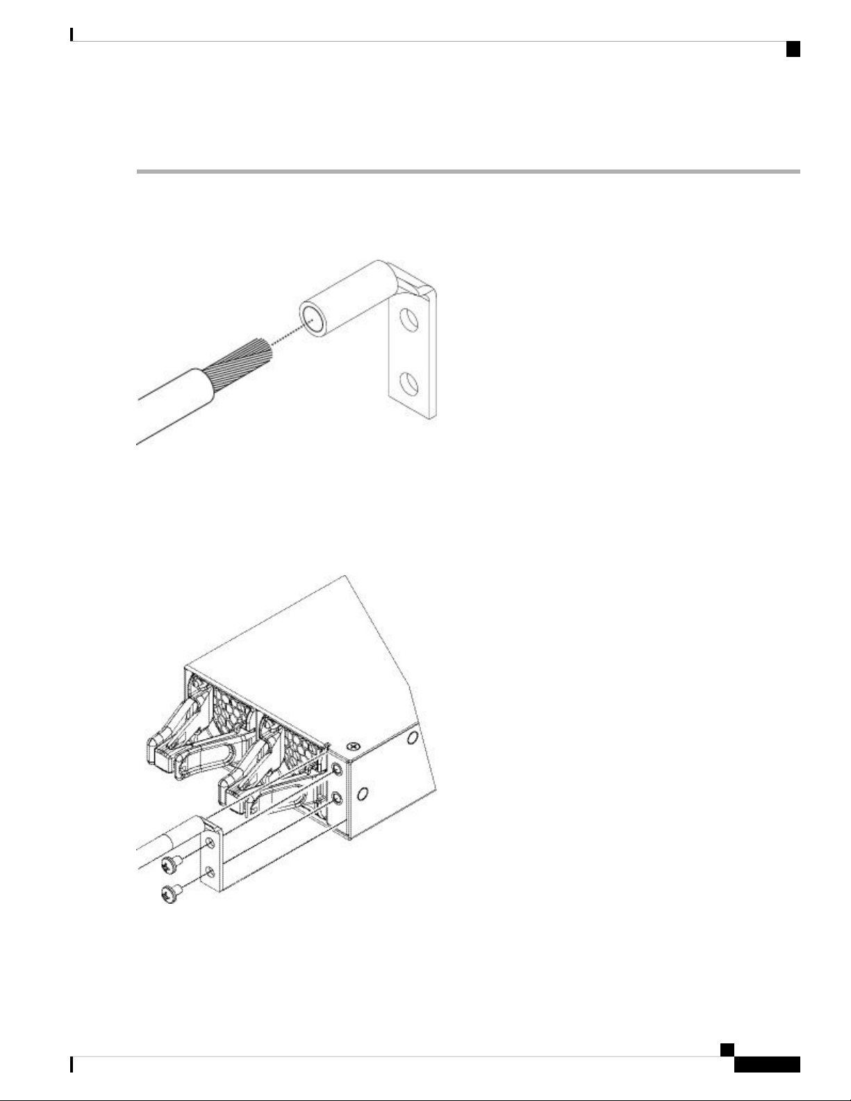
Step 1 Use a wire-stripping tool to remove approximately 0.75 in. (19 mm) of the covering from the end of the grounding cable.
Step 2 Insert the stripped end of the grounding cable into the open end of the grounding lug.
Figure 39: Insert the Cable into the Grounding Lug
Step 3 Use the crimping tool to secure the grounding cable in the grounding lug.
Step 4 Remove the adhesive label from the grounding pad on the chassis.
Step 5 Place the grounding lug against the grounding pad so that there is solid metal-to-metal contact, and insert the 2 screws
with washers through the holes in the grounding lug and into the grounding pad.
Figure 40: Attach the Grounding Lug
Step 6 Make sure that the lug and cable do not interfere with other equipment.
Cisco Firepower 4110, 4120, 4140, and 4150 Hardware Installation Guide
47
Page 52

Mount and Connect
Install the FIPS Opacity Shield
Step 7 Prepare the other end of the grounding cable and connect it to an appropriate grounding point in your site to ensure
adequate earth ground.
What to do next
Install the FIPS opacity shield if necessary. See Install the FIPS Opacity Shield, on page 48 for the procedure.
Continue with Connect Cables, Turn on Power, and Verify Connectivity, on page 53.
Install the FIPS Opacity Shield
Caution
Note
This procedure should be performed only by the Crypto Officer.
Because the FIPS opacity shield covers the serial number on the chassis, you need to copy the serial number
on a label and attach it to the chassis where it can be retrieved or viewed easily before you install the FIPS
opacity shield. You need the serial number when you call Cisco TAC.
Before you begin
You need the following to install the FIPS opacity shield:
• #1 Phillips head screwdriver
• The following items from the FIPS kit:
• One FIPS opacity shield
• Four 8-32 x .375-in. countersink screws used to attach the FIPS opacity shield to the cable
management brackets
• 15 tamper-evident labels (TELs)
• The following items from the Firepower 4100 series accessory kit:
• Two cable management brackets
• Four 8-32 x .375-in. countersink screws used to attach the cable management brackets to the slide
rail locking brackets
Step 1 Copy the serial number on a label and attach it to the chassis where it can be retrieved easily for future use if needed.
To find the serial number, see Serial Number Location, on page 5.
Step 2 Pull the chassis out of the rack until the release latches catch.
Step 3 If you have not already done so, attach a slide rail locking bracket to each side of the chassis using the six 8-32 x .375-in.
countersink Phillips head screws provided in the accessory kit.
Cisco Firepower 4110, 4120, 4140, and 4150 Hardware Installation Guide
48
Page 53

Mount and Connect
Install the FIPS Opacity Shield
Note
You should have completed this step while preforming the procedure described in Rack-Mount the Chassis,
on page 42.
Figure 41: Attach the Slide Rail Locking Bracket to the Side of the Chassis
Slide rail locking bracket2Chassis1
3
8-32 x .375-in. countersink Phillips head
screws (3 per side)
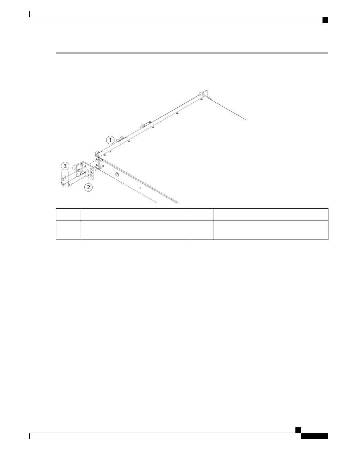
Step 4 Attach a cable management bracket to each slide rail locking bracket using the four 8-32 x .375-in. countersink Phillips
head screws provided in the accessory kit.
Cisco Firepower 4110, 4120, 4140, and 4150 Hardware Installation Guide
49
Page 54

Install the FIPS Opacity Shield
Figure 42: Attach the Cable Management Bracket to the Slide Rail Locking Bracket
Mount and Connect
Slide rail locking bracket2Cable management bracket1
3
8-32 x .375-in. countersink Phillips head
screws (2 per side)
Step 5 Connect the cables to the ports. See Connect Cables, Turn on Power, and Verify Connectivity, on page 53 for the
procedure. Make sure that the cables have enough slack to route them through the cable mounting brackets (as shown
in step 6 below).
Note
If you are installing the FIPS opacity shield after the initial product installation, the cables are connected. If
the attached cables do not have enough slack to route them through the cable mounting brackets (as shown
below), you will have to turn the power off on the appliance, remove the cables, route the cables through the
cable mounting brackets, reattach the cables, and continue with step 7 below.
Step 6 Route the cables through the openings in the cable management brackets.
Cisco Firepower 4110, 4120, 4140, and 4150 Hardware Installation Guide
50
Page 55

Mount and Connect
Figure 43: Route the Cables Through the Cable Management Brackets
Install the FIPS Opacity Shield
Step 7 Attach the FIPS opacity shield to the cable management brackets using the four 8-32 x .375-in. countersink Phillips
head screws provided in the FIPS kit.
Cisco Firepower 4110, 4120, 4140, and 4150 Hardware Installation Guide
51
Page 56

Install the FIPS Opacity Shield
Figure 44: Attach the FIPS Opacity Shield to the Cable Management Brackets
Mount and Connect
2FIPS opacity shield1
8-32 x .375-in. countersink Phillips head screws
(2 per side)
Cable management bracket3
Step 8 Attach the 15 TELs. For information on the procedure and correct placement of the TELs, see the Tamper Evidence
Label (TEL) Placement section (section 2.13 ) in the FIPS 140-2 Non Proprietary Security Policy Level 2 Validation
document.
Step 9 Attach the power cable to the chassis and connect it to an electrical outlet.
Step 10 Press the power switch on the rear panel.
Step 11 Check the power LED on the front panel. See Front Panel LEDs, on page 7 for a description of the power LED. Solid
green indicates that the chassis is powered on.
Note
When you toggle the power switch from ON to OFF, it takes several seconds for the system to power down.
Do not remove the power cable until the power LED is off. After removing power from the chassis either by
moving the power switch to OFF or unplugging the power cord, wait at least 10 seconds before turning power
back ON.
Step 12 See the quick start guide for your operating software for further configuration information:
• Cisco ASA for Firepower 4100 Quick Start Guide
Cisco Firepower 4110, 4120, 4140, and 4150 Hardware Installation Guide
52
Page 57

Mount and Connect
Connect Cables, Turn on Power, and Verify Connectivity
• Cisco Firepower Threat Defense for Firepower 4100 Quick Start Guide
Connect Cables, Turn on Power, and Verify Connectivity
Take note of the following warnings:
Warning
Warning
Warning
Warning
Statement 1021—SELV Circuit
To avoid electric shock, do not connect safety extra-low voltage (SELV) circuits to telephone-network voltage
(TNV) circuits. LAN ports contain SELV circuits, and WAN ports contain TNV circuits. Some LAN and
WAN ports both use RJ-45 connectors. Use caution when connecting cables.
Statement 1051—Laser Radiation
Invisible laser radiation may be emitted from disconnected fibers or connectors. Do not stare into beams or
view directly with optical instruments.
Statement 1053—Class 1M Laser Radiation
Class 1M laser radiation when open. Do not view directly with optical instruments.
Statement 1055—Class I and Class 1M Laser
Class I (CDRH) and Class 1M (IEC) laser products.
After rack mounting the chassis, follow these steps to connect cables, turn on power, and verify connectivity.
Step 1 Connect to the console port.
Using a serial console cable, connect a computer or terminal server to the RJ-45 serial console port (baud rate is 9600)
so that you can use the CLI for initial setup.
Step 2 Connect to the management interface.
Install the 1-Gigabit Ethernet SFP transceiver that was provided in the accessory kit in the Management port, and then
using an Ethernet cable, connect a management computer directly to the SFP.
Note
Use appropriate ESD procedures when inserting the SFP transceiver. Avoid touching the contacts at the rear,
and keep the contacts and ports free of dust and dirt. Store unused SPF transceivers in their ESD packaging.
Warning
Do not force an SFP transceiver into a socket. This can jam the transceiver and can cause permanent damage
to the transceiver, the chassis, or both.
Cisco Firepower 4110, 4120, 4140, and 4150 Hardware Installation Guide
53
Page 58
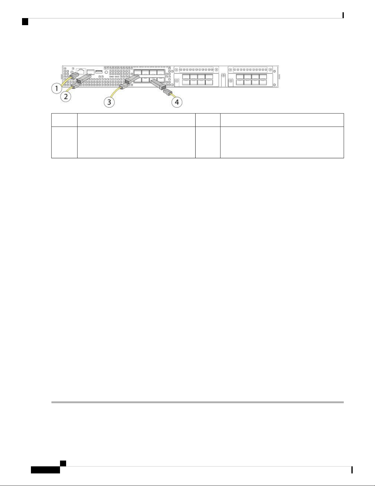
Connect Cables, Turn on Power, and Verify Connectivity
Figure 45: Connect the Cables to the Firepower 4100
Mount and Connect
1-Gigabit Ethernet Management interface2Console port (RJ-45)1
3
48 fixed-port Gigabit Ethernet data interfaces for
SFP+ transceivers
8 fixed-port Gigabit Ethernet data interfaces for
SFP+ transceivers
Flip the SFP+ over to connect in the upper ports.
Step 3 Install the SFP/SFP+ transceivers.
Install SFP/SFP+ transceivers in the Ethernet network interfaces in the fixed ports or in the network modules you have
installed taking care not to touch the contacts in the rear. Flip the SFP+ over to connect in the upper ports. The SFP+
transceiver connects in the normal way in the lower ports. The sockets on the upper row face up and the sockets on the
lower row face down.
Note
Although non-Cisco SFP transceivers are allowed, we do not recommend using them because they have not
been tested and validated by Cisco. Cisco TAC may refuse support for any interoperability problems that result
from using an untested third-party SFP transceiver. See Supported SFP/SFP+ and QSFP Transceivers, on page
21 for a list of supported Cisco transceivers.
Step 4 Connect to the Ethernet interfaces.
Use the proper cable to connect the SFP/SFP+ transceivers in the fixed ports or in the network modules you have installed.
Step 5 (Optional) If you are installing the FIPS opacity shield, continue with step 6 in Install the FIPS Opacity Shield, on page
48.
Step 6 Attach the power cable to the chassis and connect it to an electrical outlet.
Step 7 Press the power switch on the rear panel.
Step 8 Check the power LED on the front panel. Solid green indicates that the chassis is powered on.
Note
When you toggle the power switch from ON to OFF, it takes several seconds for the system to power off. Do
not remove the power cable until the power LED is off. After removing power from the chassis either by moving
the power switch to OFF or unplugging the power cord, wait at least 10 seconds before turning power back
ON.
Step 9 See the quick start guide for your operating software for further configuration information:
• Cisco ASA for Firepower 4100 Quick Start Guide
• Cisco Firepower Threat Defense for Firepower 4100 Quick Start Guide
Cisco Firepower 4110, 4120, 4140, and 4150 Hardware Installation Guide
54
Page 59

CHAPTER 4
Maintenance and Upgrade
• Remove and Replace the Network Module, on page 55
• Remove and Replace the Fan Module, on page 58
• Remove and Replace the SSD, on page 59
• Remove and Replace the Power Supply Module, on page 61
• Connect the DC Power Supply Module, on page 64
• Secure the Power Cord on the AC Power Supply Module, on page 70
Remove and Replace the Network Module
Take note of the following warnings:
Warning
Warning
Warning
Statement 60—UL- and CSA-Certified Equipment Warning
This card is intended to be installed in UL- and CSA-certified equipment in the field by the user in the
manufacturer's defined operator access area. Check the equipment manufacturer to verify/confirm that your
equipment is suitable for user-installed application cards.
Statement 1029—Blank Faceplates and Cover Panels
Blank faceplates and cover panels serve three important functions: they prevent exposure to hazardous voltages
and currents inside the chassis; they contain electromagnetic interference (EMI) that might disrupt other
equipment; and they direct the flow of cooling air through the chassis. Do not operate the system unless all
cards, faceplates, front covers, and rear covers are in place.
Statement 1030—Equipment Installation
Only trained and qualified personnel should be allowed to install, replace, or service this equipment.
Cisco Firepower 4110, 4120, 4140, and 4150 Hardware Installation Guide
55
Page 60

Remove and Replace the Network Module
Maintenance and Upgrade
Warning
Warning
Warning
Statement 1040—Product Disposal
Ultimate disposal of this product should be handled according to all national laws and regulations.
Statement 1073—No User-Serviceable Parts
No user-serviceable parts inside. Do not open.
Statement 1077—Do Not Operate Unit Without Covers
The covers are an integral part of the safety design of the product. Do not operate the unit without the covers
installed.
Hot Swapping
Starting with FXOS 2.3.1, the Firepower 10-G and 40-G non-fail-to-wire network modules support hot
swapping, but you must hot swap with an identical network module, that is, a network module with the
same PID. See Product ID Numbers, on page 25 for the network module PIDs. You must bring the
network module offline using the appropriate CLI commands before removing the network module from
the chassis so that all network module configuration is saved. See the “Taking a Network Module Offline
or Online” topic in the Security Module/Engine Management chapter in the Cisco FXOS Firepower
Chassis Manager Configuration Guide.
Caution
We do not recommend that you remove the network module without bringing it properly offline using
the appropriate CLI commands.
Note
You must have ROMMON 1.0.10 or later on the Supervisor to support hot swapping. For the ROMMON
upgrade procedure, see the "Firmware Upgrade" topic in the Image Management chapter in the Cisco
FXOS Firepower Chassis Manager Configuration Guide for your software version.
To remove and replace the network modules that do not currently support hot swapping, power off the chassis,
replace the network module, and then power the chassis back on.
Acknowledgment is necessary if you decommission and physically remove a network module and do not
replace it, or if you replace it with another PID. See the "Acknowledging a Security Module/Engine” topic
in the Security Module/Engine Management chapter in the Cisco FXOS Firepower Chassis Manager
Configuration Guide.
Step 1 Save your configuration (if removing a network module that does not support hot swapping).
Step 2 Do one of the following:
a) Power down the chassis by moving the power switch to the OFF position (if removing a network module that does
not support hot swapping).
Cisco Firepower 4110, 4120, 4140, and 4150 Hardware Installation Guide
56
Page 61

Maintenance and Upgrade
Remove and Replace the Network Module
See Features, on page 1 for more information about the power switch.
b) Bring the network module off line using the appropriate CLI command (if removing a network module that supports
hot swapping). All network module configuration is saved.
Step 3 To remove a network module from the chassis, loosen the captive screw on the lower left side of the network module
and pull out the handle that is connected to the screw. This mechanically ejects the network module from the slot.
Figure 46: Remove the Network Module
If the slot is to remain empty, install a blank faceplate to ensure proper airflow and to keep dust out of the chassis;
otherwise, install another network module.
Step 4 To replace a network module, hold the network module in front of the network module slot on the right of the chassis
and pull the network module handle out.
Step 5 Slide the network module into the slot and push it firmly into place until the handle is flush with the front of the network
module.
Step 6 Tighten the captive screw on the lower left side of the network module.
Step 7 Do one of the following:
a) Power up the chassis so that the new network module is recognized (if the new network module does not support hot
swapping).
b) Bring the new network module online using the appropriate CLI command (if the new network module supports hot
swapping). The saved network module configuration is automatically reapplied when the network module is back
online.
Note
If you install a network module that is a different PID than the original network module, the saved
configuration is deleted and the default configuration is applied. You must enter the acknowledge command
to confirm the network module PID change.
What to do next
Follow the procedures in the FXOS Configuration Guide to connect to the network module and make sure
that it has been discovered correctly by the Firepower 4100.
Cisco Firepower 4110, 4120, 4140, and 4150 Hardware Installation Guide
57
Page 62

Remove and Replace the Fan Module
Remove and Replace the Fan Module
Take note of the following warnings:
Maintenance and Upgrade
Warning
Warning
Warning
Warning
Statement 60—UL- and CSA-Certified Equipment Warning
This card is intended to be installed in UL- and CSA-certified equipment in the field by the user in the
manufacturer's defined operator access area. Check the equipment manufacturer to verify/confirm that your
equipment is suitable for user-installed application cards.
Statement 1030—Equipment Installation
Only trained and qualified personnel should be allowed to install, replace, or service this equipment.
Statement 1040—Product Disposal
Ultimate disposal of this product should be handled according to all national laws and regulations.
Statement 1073—No User-Serviceable Parts
No user-serviceable parts inside. Do not open.
Warning
Statement 1077—Do Not Operate Unit Without Covers
The covers are an integral part of the safety design of the product. Do not operate the unit without the covers
installed.
You can remove and replace fan modules while the system is running. The air flow moves from front to back.
If you remove a fan or a fan fails, the other fans operate at full speed, which can be noisy.
Note
The system supports operation with a single fan failure (N+1 fan redundancy), but do not run the system for
an extended amount of time without all fan modules installed. Keep removal and replacement time at 3 minutes.
Remove and replace one fan module at a time.
Step 1 To remove a fan module, face the rear of the chassis, and grasp the handle of the fan module.
Step 2 Squeeze the handle to disengage the latches on the left and right of the fan module.
Step 3 Pull the fan module out of the chassis.
Cisco Firepower 4110, 4120, 4140, and 4150 Hardware Installation Guide
58
Page 63
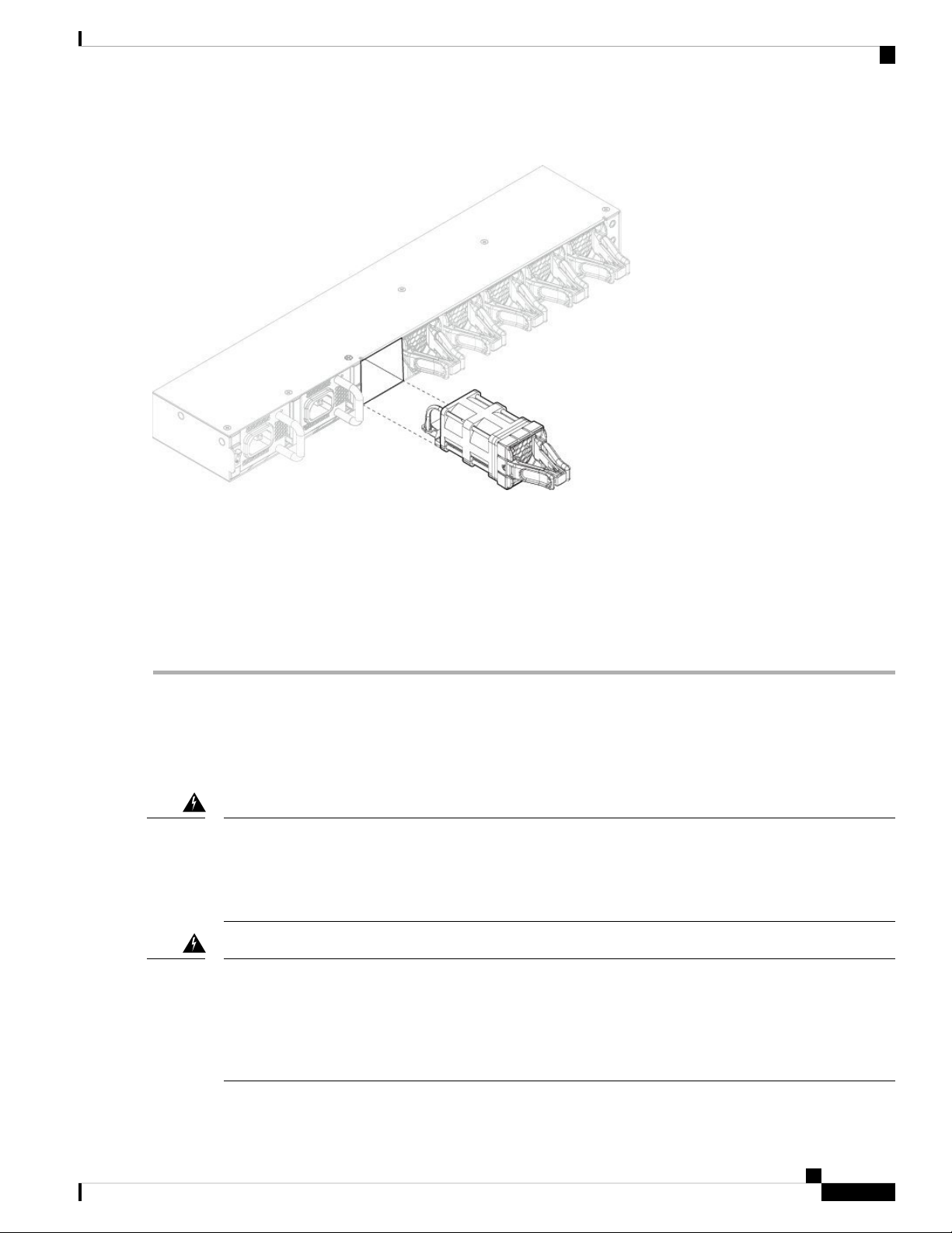
Maintenance and Upgrade
Figure 47: Remove the Fan Module
Remove and Replace the SSD
Step 4 To replace a fan module, hold the fan module in front of the fan slot.
Step 5 Push the fan module into the chassis until it is properly seated and the latches snap into place.
If the system is powered on, listen for the fans. You should immediately hear the fans operating. If you do not hear the
fans, make sure the fan module is inserted completely into the chassis and the faceplate is flush with the outside surface
of the chassis.
Step 6 Verify that the fan is operational by checking the fan module LED. See Front Panel LEDs, on page 7 for a description
of the fan LEDs.
Remove and Replace the SSD
Take note of the following warnings:
Warning
Statement 60—UL- and CSA-Certified Equipment Warning
This card is intended to be installed in UL- and CSA-certified equipment in the field by the user in the
manufacturer's defined operator access area. Check the equipment manufacturer to verify/confirm that your
equipment is suitable for user-installed application cards.
Warning
Statement 1029—Blank Faceplates and Cover Panels
Blank faceplates and cover panels serve three important functions: they prevent exposure to hazardous voltages
and currents inside the chassis; they contain electromagnetic interference (EMI) that might disrupt other
equipment; and they direct the flow of cooling air through the chassis. Do not operate the system unless all
cards, faceplates, front covers, and rear covers are in place.
Cisco Firepower 4110, 4120, 4140, and 4150 Hardware Installation Guide
59
Page 64

Remove and Replace the SSD
Maintenance and Upgrade
Warning
Warning
Warning
Warning
Statement 1030—Equipment Installation
Only trained and qualified personnel should be allowed to install, replace, or service this equipment.
Statement 1040—Product Disposal
Ultimate disposal of this product should be handled according to all national laws and regulations.
Statement 1073—No User-Serviceable Parts
No user-serviceable parts inside. Do not open.
Statement 1077—Do Not Operate Unit Without Covers
The covers are an integral part of the safety design of the product. Do not operate the unit without the covers
installed.
Although the hardware supports removing and replacing SSDs while the system is running, the software does
not currently support hot swapping. You must power down the chassis to remove and replace SSDs.
Note
If your Firepower 4100 is running Firepower Threat Defense software, we recommend that you upgrade to
the latest version (at least to Version 6.1.0) to take advantage of software updates that enhance SSD management
performance and longevity.
You can install an MSP in the second SSD slot (SSD slot 2). The MSP stores threat detection results for use
in future analysis. It supports the Advanced Malware Protection software feature. The MSP is supported
beginning in FXOS 2.0.1. It is used as both storage and as the Malware application repository. RAID is not
supported.
Caution
Do not switch the 2 SSDs. The MSP MUST be installed in slot 2. If you remove it and install it in slot 1, all
stored file capture data is lost.
Step 1 Save your configuration.
Step 2 Power down the chassis by moving the power switch to the OFF position. See Features, on page 1 for more information
about the power switch.
Step 3 To remove an SSD, face the front of the chassis, loosen the two captive screws on the SSD, and gently pull it out of slot
1 of the chassis.
Cisco Firepower 4110, 4120, 4140, and 4150 Hardware Installation Guide
60
Page 65

Maintenance and Upgrade
Figure 48: Remove the SSD
Remove and Replace the Power Supply Module
Step 4 To replace the SSD, make sure the power switch is still in the OFF position, and then hold the SSD in front of slot 1 and
push it in gently until it is seated.
Step 5 To install the MSP SSD, make sure the power switch is still in the OFF position and then remove the blank faceplate in
Slot 2 by loosening the captive screws on either side of the faceplate.
Step 6 Hold the MSP SSD in front of slot 2 and push it in gently until it is seated.
Caution
Do not switch the 2 SSDs. The MSP MUST be installed in slot 2. If you remove it and install it in slot 1, all
stored file capture data is lost.
Step 7 Tighten the captive screws on either side of the SSD.
Step 8 Verify that the SSD is operational by checking the SSD LED. See Front Panel LEDs, on page 7 for a description of the
fan LEDs.
Remove and Replace the Power Supply Module
Take note of the following warnings:
Warning
Statement 1002—DC Power Supply
When stranded wiring is required, use approved wiring terminations, such as closed-loop or spade-type with
upturned lugs. These terminations should be the appropriate size for the wires and should clamp both the
insulation and conductor.
Cisco Firepower 4110, 4120, 4140, and 4150 Hardware Installation Guide
61
Page 66

Remove and Replace the Power Supply Module
Maintenance and Upgrade
Warning
Warning
Warning
Warning
Statement 1003—DC Power Disconnection
Before performing any of the following procedures, ensure that power is removed from the DC circuit.
Statement 1005—Circuit Breaker
This product relies on the building's installation for short-circuit (overcurrent) protection. Ensure that the
protective device is rated not great than: AC power 120VAC, 20A (US), 240VAC, 16A (EU), DC power 60V,
35A.
Statement 1022—Disconnect Device
A readily accessible two-poled disconnect device must be incorporated in the fixed wiring.
Statement 1025—Use Copper Conductors Only
Use copper conductors only.
Warning
Warning
Warning
Warning
Statement 1028—More Than One Power Supply
This unit might have more than one power supply connection. All connections must be removed to de-energize
the unit.
Statement 1030—Equipment Installation
Only trained and qualified personnel should be allowed to install, replace, or service this equipment.
Statement 1040—Product Disposal
Ultimate disposal of this product should be handled according to all national laws and regulations.
Statement 1045—Short-Circuit Protection
This product requires short-circuit (overcurrent) protection to be provided as part of the building installation.
Install only in accordance with national and local wiring regulations.
Cisco Firepower 4110, 4120, 4140, and 4150 Hardware Installation Guide
62
Page 67

Maintenance and Upgrade
Remove and Replace the Power Supply Module
Warning
Statement 1046—Installing or Replacing the Unit
When installing or replacing the unit, the ground connection must always be made first and disconnected last.
Warning
Statement 1073—No User-Serviceable Parts
No user-serviceable parts inside. Do not open.
Warning
Statement 1077—Do Not Operate Unit Without Covers
The covers are an integral part of the safety design of the product. Do not operate the unit without the covers
installed.
You can remove and replace power supply modules while the system is running.
Step 1 To remove a power supply module, face the back of the chassis and grasp the handle.
Step 2 Press the latch found on the lower right of the power supply to disengage the power supply.
Step 3 Place your other hand under the power supply module to support it while you slide it out of the chassis.
Cisco Firepower 4110, 4120, 4140, and 4150 Hardware Installation Guide
63
Page 68

Connect the DC Power Supply Module
Figure 49: Remove the Power Supply Module
Maintenance and Upgrade
If the slot is to remain empty, install a blank faceplate to ensure proper airflow and to keep dust out of the chassis;
otherwise, install another power supply module.
Step 4 To replace a power supply module, hold the power supply module with both hands and slide it into the power supply
module bay.
Step 5 Push in the power supply module gently until you hear the latch engage and it is seated. Verify the power supply module
is operating correctly by checking the power supply module LED. See Power Supply Modules, on page 18 for a description
of the power supply module LEDs.
Connect the DC Power Supply Module
Take note of the following warnings:
Warning
Statement 1002—DC Power Supply
When stranded wiring is required, use approved wiring terminations, such as closed-loop or spade-type with
upturned lugs. These terminations should be the appropriate size for the wires and should clamp both the
insulation and conductor.
Cisco Firepower 4110, 4120, 4140, and 4150 Hardware Installation Guide
64
Page 69

Maintenance and Upgrade
Connect the DC Power Supply Module
Warning
Warning
Warning
Warning
Statement 1003—DC Power Disconnection
Before performing any of the following procedures, ensure that power is removed from the DC circuit.
Statement 1005—Circuit Breaker
This product relies on the building's installation for short-circuit (overcurrent) protection. Ensure that the
protective device is rated not great than: AC power 120VAC, 20A (US), 240VAC, 16A (EU), DC power 60V,
35A.
Statement 1017—Restricted Area
This unit is intended for installation in restricted access areas. A restricted access area can be accessed only
through the use of a special tool, lock and key, or other means of security.
Statement 1022—Disconnect Device
A readily accessible two-poled disconnect device must be incorporated in the fixed wiring.
Warning
Warning
Warning
Warning
Statement 1025—Use Copper Conductors Only
Use copper conductors only.
Statement 1028—More Than One Power Supply
This unit might have more than one power supply connection. All connections must be removed to de-energize
the unit.
Statement 1030—Equipment Installation
Only trained and qualified personnel should be allowed to install, replace, or service this equipment.
Statement 1040—Product Disposal
Ultimate disposal of this product should be handled according to all national laws and regulations.
Cisco Firepower 4110, 4120, 4140, and 4150 Hardware Installation Guide
65
Page 70

Connect the DC Power Supply Module
Maintenance and Upgrade
Warning
Warning
Warning
Warning
Statement 1045—Short-Circuit Protection
This product requires short-circuit (overcurrent) protection to be provided as part of the building installation.
Install only in accordance with national and local wiring regulations.
Statement 1046—Installing or Replacing the Unit
When installing or replacing the unit, the ground connection must always be made first and disconnected last.
Statement 1077—Do Not Operate Unit Without Covers
The covers are an integral part of the safety design of the product. Do not operate the unit without the covers
installed.
Statement 1073—No User-Serviceable Parts
No user-serviceable parts inside. Do not open.
Warning
Note
Statement 1086—Power Terminals, Replace Cover
Hazardous voltage or energy may be present on power terminals. Always replace cover when terminals are
not in service. Be sure uninsulated conductors are not accessible when cover is in place.
Each DC input power cable is terminated at the PDU by a cable lug, as shown in the following figure.
DC input power cables must be connected to the PDU terminal studs in the proper positive (+) and negative
(–) polarity. In some cases, the DC cable leads are labeled, which is a relatively safe indication of the polarity.
However, you must verify the polarity by measuring the voltage between the DC cable leads. When making
the measurement, the positive (+) lead and the negative (–) lead must always match the (+) and (–) labels on
the power distribution unit.
Figure 50: DC Input Power Cable Lug
Cisco Firepower 4110, 4120, 4140, and 4150 Hardware Installation Guide
66
Page 71

Maintenance and Upgrade
Note
Connect the DC Power Supply Module
To avoid hazardous conditions, all components in the area where DC input power is accessible must be
properly insulated. Therefore, before installing the DC cable lugs, be sure to insulate the lugs according to
the manufacturer's instructions
This procedure describes how to install the DC power supply input power leads to the Firepower 4100 DC
input power supply on the rear PDU of the chassis.
Before you begin
• The color coding of the DC input power supply leads depends on the color coding of the DC power
source at your site. Make sure that the lead color coding you choose for the DC input power supply
matches the lead color coding used at the DC power source and verify that the power source is connected
to the negative (–) terminal and to the positive (+) terminal on the power supply.
• For DC input power cables, the wire gauge is based on the National Electrical Code (NEC) and local
codes for 26 amp service at nominal DC input voltage (–40/–72 VDC). One pair of cable leads, source
DC (–) and source DC return (+), are required for each power distribution unit (PDU). These cables are
available from any commercial cable vendor. All DC input power cables for the chassis should be 10gauge
wire and cable lengths should match within 10 percent of deviation.
• Tools needed:
• Phillips head screwdriver
• 10-mm wrench or socket
• Connectors and wire for the DC circuit or circuits
Step 1 Install the DC power supply module in the chassis and make note of the bay number so you can connect the wiring to
the correct terminals on the DC power supply module at the rear of the chassis. See Remove and Replace the Power
Supply Module, on page 61 for the procedure.
Step 2 Verify that the power is off to the DC circuit on the power supply module that you are installing.
Step 3 Make sure that all site power and grounding requirements have been met.
Step 4 To remove the plastic cover from the terminal block, insert a flat screw driver on the side of the plastic cover and pry
it off.
Cisco Firepower 4110, 4120, 4140, and 4150 Hardware Installation Guide
67
Page 72

Maintenance and Upgrade
Connect the DC Power Supply Module
Figure 51: Remove the Plastic Cover
Step 5 To prevent any contact with metal lead on the ground wire and the plastic cover, you must wrap the positive and negative
lead cables with sleeving. Insulate the lug with shrink sleeving for each lead wire if using noninsulated crimp terminals.
Sleeving is not required for insulated terminals.
Step 6 Remove the two M5 screws.
Figure 52: Remove the M5 Screws
Step 7 For easier cable management, insert the negative lead cable first. Replace the grounding lug with the cable in the
following order—wire terminal, then the screw with the captive washer.
Cisco Firepower 4110, 4120, 4140, and 4150 Hardware Installation Guide
68
Page 73

Maintenance and Upgrade
Figure 53: Insert the Cables
Connect the DC Power Supply Module
Step 8 Tighten the M5 screw with the captive washer to the recommended torque of 5 in-lbs for the positive stud and wire.
Secure the wires coming in from the terminal block so that they cannot be disturbed by casual contact.
Figure 54: Tighten the M5 Screws
Step 9 Replace the terminal block plastic cover. The plastic cover is slotted and keyed to fit correctly over the terminal block.
This cover should always be in place when power is applied to the terminals.
Cisco Firepower 4110, 4120, 4140, and 4150 Hardware Installation Guide
69
Page 74
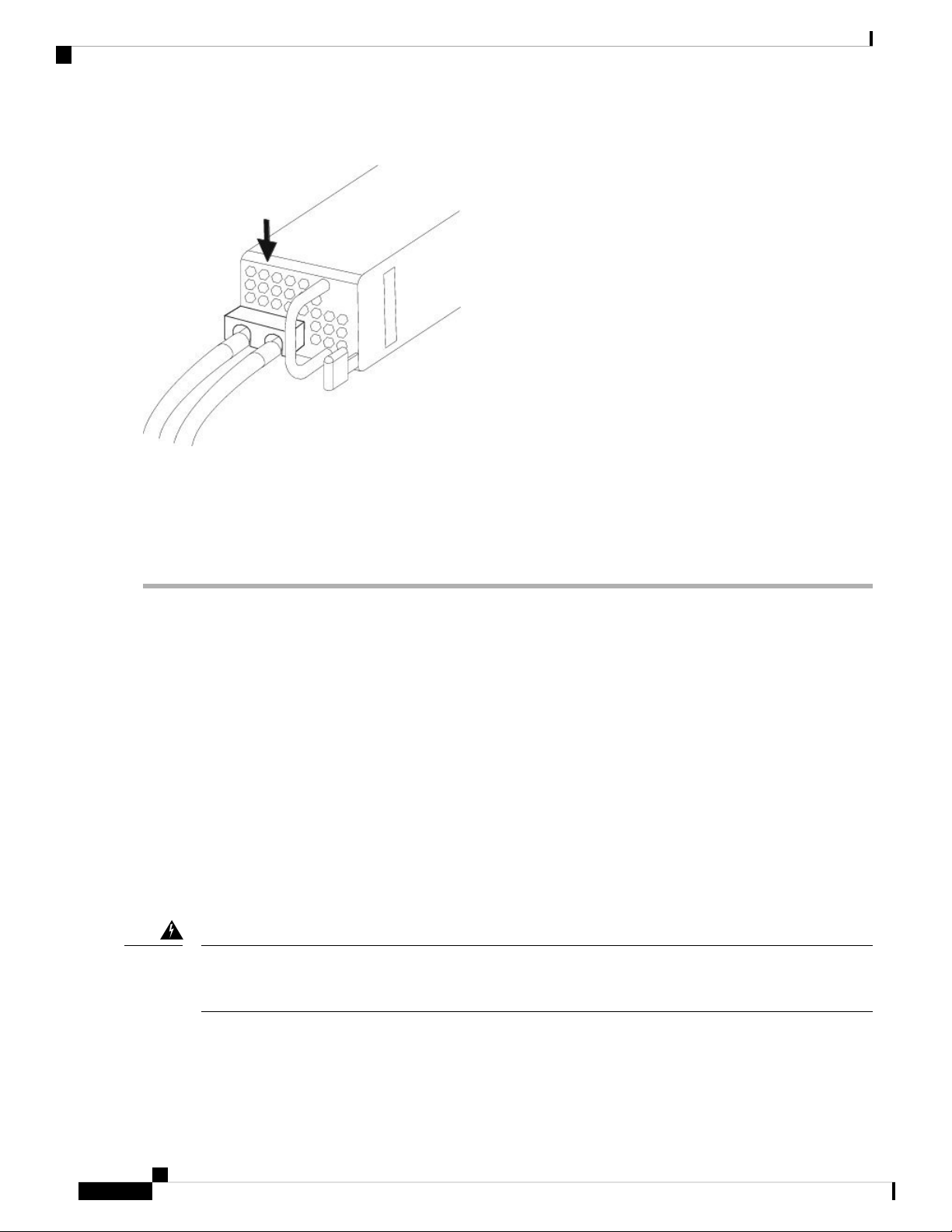
Maintenance and Upgrade
Secure the Power Cord on the AC Power Supply Module
Figure 55: Replace the Plastic Cover
Step 10 Set the DC disconnect switch in the circuit to ON. In a system with multiple power supplies, connect each power supply
to a separate DC power source. In the event of a power source failure, if the second source is still available, it can
maintain system operation.
Step 11 Verify power supply operation by checking the power supply LED on the front of the chassis. See Front Panel LEDs,
on page 7 for a description of the LEDs.
Secure the Power Cord on the AC Power Supply Module
To secure the power supply module against accidental removal and thus prevent disrupting system performance,
use the tie wrap and clamp provided in the accessories kit that ships with your Firepower 4100. There are two
different tie wrap and clamp combinations to be used with either the Flextronics or Artesyn power supply
module.
To verify which power supply module you have, look at the vendor name on the top of the power supply
module. If you cannot remove the power supply module, you can count the number of full hexagonal vent
holes on the front of the power supply module in the row directly next to the word 'FAIL.' Flextronics has
five holes and Artesyn has four holes.
The black tie wrap is used with the Flextronics power supply module and the off-white tie wrap is used with
the Artesyn power supply module. The black clamp works with both. See the figures below.
Take note of the following warnings:
Warning
Statement 1030—Equipment Installation
Only trained and qualified personnel should be allowed to install, replace, or service this equipment.
Cisco Firepower 4110, 4120, 4140, and 4150 Hardware Installation Guide
70
Page 75

Maintenance and Upgrade
Secure the Power Cord on the AC Power Supply Module
Warning
Statement 1073—No User-Serviceable Parts
No user-serviceable parts inside. Do not open.
Step 1 Attach the clamp to the tie wrap by holding the clamp with the loop side on the bottom and sliding the tie wrap through
the box-shaped channel above the clamp (see the following figure).
One side of the tie wrap has evenly spaced ridges and the other is smooth. Be sure the ridged side is face up and that you
slide it through the open side of the channel. You will hear a click as the tie slides through—it moves in one direction
only. To remove the tie wrap from the clamp, push the lever on the closed side of the box-shaped channel and slide out
the tie wrap.
Figure 56: Tie Wrap Through the Box Channel of the Clamp
Step 2 Attach the clamp to the power supply module:
a) Locate the hexagonal ventilation hole on the power supply module at the center of the plug just below the power
connector body (see the following figures).
b) Plug the snapping portion of the tie wrap into the hexagonal hole.
c) With the clamp side facing up, push the tie wrap in until it is fully engaged.
Caution
Make sure you have the correct location because you cannot remove the tie wrap from the power supply
module once you have installed it without damaging the tie wrap.
Tie wrap2Box channel1
Cisco Firepower 4110, 4120, 4140, and 4150 Hardware Installation Guide
71
Page 76

Secure the Power Cord on the AC Power Supply Module
Figure 57: Flextronics Power Supply Module
Maintenance and Upgrade
Hexagonal hole2Flextronics tie wrap1
Figure 58: Artesyn Power Supply Module
Step 3 Secure the clamp:
a) Plug in the power supply power cord and wrap the clamp around the over mold portion of the power cord.
b) Squeeze the clamp ends together to the power supply so that the annular teeth engage with the mate on the clamp.
c) Make sure the clamp fits snugly into the over mold.
d) Adjust the clamp position on the tie wrap so that the clamp is tight against the front of the over mold and the power
cord cannot be removed by lightly pulling on it.
Hexagonal hole2Artesyn tie wrap1
Cisco Firepower 4110, 4120, 4140, and 4150 Hardware Installation Guide
72
Page 77
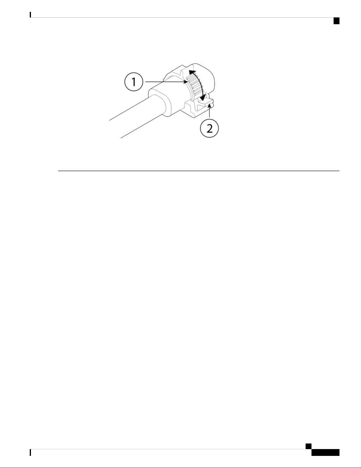
Maintenance and Upgrade
Secure the Power Cord on the AC Power Supply Module
Figure 59: Clamp on Over Mold of Power Cord
Step 4 If you need to remove the power cord, push the release tab on the clamp to force the annular clamp teeth to disengage
and the clamp opens up. You can then remove the clamp from the power cord.
Cisco Firepower 4110, 4120, 4140, and 4150 Hardware Installation Guide
73
Page 78

Secure the Power Cord on the AC Power Supply Module
Maintenance and Upgrade
Cisco Firepower 4110, 4120, 4140, and 4150 Hardware Installation Guide
74
 Loading...