

Page 1

Cisco Firepower Management Center 1600, 2600, and 4600 Hardware Installation Guide
First Published: 2019-06-26
Americas Headquarters
Cisco Systems, Inc.
170 West Tasman Drive
San Jose, CA 95134-1706
USA
http://www.cisco.com
Tel: 408 526-4000
800 553-NETS (6387)
Fax: 408 527-0883
Page 2

THE SPECIFICATIONS AND INFORMATION REGARDING THE PRODUCTS IN THIS MANUAL ARE SUBJECT TO CHANGE WITHOUT NOTICE. ALL STATEMENTS,
INFORMATION, AND RECOMMENDATIONS IN THIS MANUAL ARE BELIEVED TO BE ACCURATE BUT ARE PRESENTED WITHOUT WARRANTY OF ANY KIND,
EXPRESS OR IMPLIED. USERS MUST TAKE FULL RESPONSIBILITY FOR THEIR APPLICATION OF ANY PRODUCTS.
THE SOFTWARE LICENSE AND LIMITED WARRANTY FOR THE ACCOMPANYING PRODUCT ARE SET FORTH IN THE INFORMATION PACKET THAT SHIPPED WITH
THE PRODUCT AND ARE INCORPORATED HEREIN BY THIS REFERENCE. IF YOU ARE UNABLE TO LOCATE THE SOFTWARE LICENSE OR LIMITED WARRANTY,
CONTACT YOUR CISCO REPRESENTATIVE FOR A COPY.
The Cisco implementation of TCP header compression is an adaptation of a program developed by the University of California, Berkeley (UCB) as part of UCB's public domain version of
the UNIX operating system. All rights reserved. Copyright©1981, Regents of the University of California.
NOTWITHSTANDING ANY OTHER WARRANTY HEREIN, ALL DOCUMENT FILES AND SOFTWARE OF THESE SUPPLIERS ARE PROVIDED “AS IS" WITH ALL FAULTS.
CISCO AND THE ABOVE-NAMED SUPPLIERS DISCLAIM ALL WARRANTIES, EXPRESSED OR IMPLIED, INCLUDING, WITHOUT LIMITATION, THOSE OF
MERCHANTABILITY, FITNESS FOR A PARTICULAR PURPOSE AND NONINFRINGEMENT OR ARISING FROM A COURSE OF DEALING, USAGE, OR TRADE PRACTICE.
IN NO EVENT SHALL CISCO OR ITS SUPPLIERS BE LIABLE FOR ANY INDIRECT, SPECIAL, CONSEQUENTIAL, OR INCIDENTAL DAMAGES, INCLUDING, WITHOUT
LIMITATION, LOST PROFITS OR LOSS OR DAMAGE TO DATA ARISING OUT OF THE USE OR INABILITY TO USE THIS MANUAL, EVEN IF CISCO OR ITS SUPPLIERS
HAVE BEEN ADVISED OF THE POSSIBILITY OF SUCH DAMAGES.
Any Internet Protocol (IP) addresses and phone numbers used in this document are not intended to be actual addresses and phone numbers. Any examples, command display output, network
topology diagrams, and other figures included in the document are shown for illustrative purposes only. Any use of actual IP addresses or phone numbers in illustrative content is unintentional
and coincidental.
All printed copies and duplicate soft copies of this document are considered uncontrolled. See the current online version for the latest version.
Cisco has more than 200 offices worldwide. Addresses and phone numbers are listed on the Cisco website at www.cisco.com/go/offices.
Cisco and the Cisco logo are trademarks or registered trademarks of Cisco and/or its affiliates in the U.S. and other countries. To view a list of Cisco trademarks, go to this URL: www.cisco.com
go trademarks. Third-party trademarks mentioned are the property of their respective owners. The use of the word partner does not imply a partnership relationship between Cisco and any
other company. (1721R)
©
2019 Cisco Systems, Inc. All rights reserved.
Page 3

CONTENTS
CHAPTER 1
CHAPTER 2
Overview 1
Features 1
Package Contents 3
Serial Number Locations 4
Front Panel 5
Front Panel LEDs 7
Rear Panel 10
Rear Panel LEDs 11
Power Supply 12
Hardware Specifications 13
Product ID Numbers 14
Power Cord Specifications 14
Installation Preparation 23
Installation Warnings 23
Safety Recommendations 25
CHAPTER 3
Maintain Safety with Electricity 25
Prevent ESD Damage 26
Site Environment 26
Power Supply Considerations 26
Rack Configuration Considerations 27
Mount and Connect 29
Unpack and Inspect the Chassis 29
Rack-Mount the Chassis 29
Connect Cables, Turn on Power, and Verify Connectivity 32
Cisco Firepower Management Center 1600, 2600, and 4600 Hardware Installation Guide
iii
Page 4

Contents
CHAPTER 4
Maintenance and Upgrade 35
Power Button Shutdown 35
Remove and Replace a Drive 36
Remove and Replace a Power Supply 38
Cisco Firepower Management Center 1600, 2600, and 4600 Hardware Installation Guide
iv
Page 5

Features
CHAPTER 1
Overview
• Features, on page 1
• Package Contents, on page 3
• Serial Number Locations, on page 4
• Front Panel, on page 5
• Front Panel LEDs, on page 7
• Rear Panel, on page 10
• Rear Panel LEDs, on page 11
• Power Supply, on page 12
• Hardware Specifications, on page 13
• Product ID Numbers, on page 14
• Power Cord Specifications, on page 14
The Cisco Firepower Management Center (FMC) 1600, 2600, and 4600 management appliances run software
that provides extensive intelligence about the users, applications, devices, threats, and vulnerabilities that exist
in your network. It also uses this information to analyze your network’s vulnerabilities. It then provides tailored
recommendations on what security policies to put in place and what security events you should investigate.
See Product ID Numbers, on page 14 for a list of the field-replaceable product IDs (PIDs) associated with
the FMC 1600, 2600, and 4600. You can remove and replace drives and power supplies. For all other internal
component failures, you must send your chassis for RMA.
The FMC management appliances support Cisco Firepower Threat Defense software. See the Cisco Firepower
Compatibility Guide, which provides Cisco Firepower software and hardware compatibility, including operating
system and hosting environment requirements, for each supported Firepower version.
Note
The FMC 1600, 2600, and 4600 are certified for Federal Information Processing Standards (FIPS) 140-2
beginning in Cisco Firepower version 6.4.1. See the "Security Certifications Compliance" topic in the
"Appliance Platform Settings" chapter in the Firepower Management Center Configuration Guide for the
instructions on how to enable security certifications compliance.
The following table lists the features of the FMC 1600, 2600, and 4600.
Cisco Firepower Management Center 1600, 2600, and 4600 Hardware Installation Guide
1
Page 6
Features
Overview
Table 1: FMC 1600, 2600, and 4600 Features
460026001600Feature
1 RUForm factor
Rack mount
Airflow
Pullout asset card
Flex flash card
Grounding hole
Processor
Yes
Standard 19-in. (48.3 cm) 4-post EIA rack
Front to rear
Cold aisle to hot aisle
Displays the serial number and the MAC address for the two built-in management
ports.
32 GB (for vMedia)
Internal component only; not field-replaceable
Yes
Two threaded holes for dual-hole grounding lug
Use is optional; the supported AC power supplies have internal grounding, so
no additional chassis grounding is required.
YesLocator beacon
YesPower switch
One Intel Xeon 4110
processor
Two Intel Xeon 4110
processors
Two Intel Xeon 4116
processors
RDIMMs
Internal component only;
not field-replaceable
Management ports
USB ports
VGA port
128-GB RAM64-GB RAM32-GB RAMMemory
Two 16-GB
DDR4-2400-MHz
DIMMs
Four 16-GB
DDR4-2400-MHz
DIMMs
Eight 16-GB
DDR4-2400-MHz
DIMMs
Two built-in RJ-45 SFP+ ports
Support for 1000 Mbps, 1 Gbps, and 10 Gbps
The primary management port is eth0. You can use eth1, eth2, and eth3 as
secondary management or event ports.
Two
USB 3.0 Type A
One 3-row 15-pin DB-15 connector
Enabled by default
Two fixed SFP+ portsSFP ports
SFP-10G-SR (10 GB)Supported SFP+
Cisco Firepower Management Center 1600, 2600, and 4600 Hardware Installation Guide
2
Page 7
Overview
Package Contents
460026001600Feature
Serial console port
System power
Fans
Storage
RAID controller
Package Contents
One
RJ-45 serial port running RS-232 (RS-232D TIA-561)
Two 770-W AC power supplies
Hot-swappable and redundant as 1+1
2626 BTU/hrPower consumption
Six fans for front-to-rear cooling
Internal component only; not field-replaceable
Two 1.2-TB 10-K SAS
HDDs
RAID 1, hot-swappable
One
The chassis has a dedicated internal riser for a PCIe-style Cisco modular RAID
controller card.
Internal component only; not field-replaceable
Four 600-GB 10-K SAS
HDDs
RAID 5, hot-swappable
Ten 1.2-TB SAS SSDs
RAID 6, hot-swappable
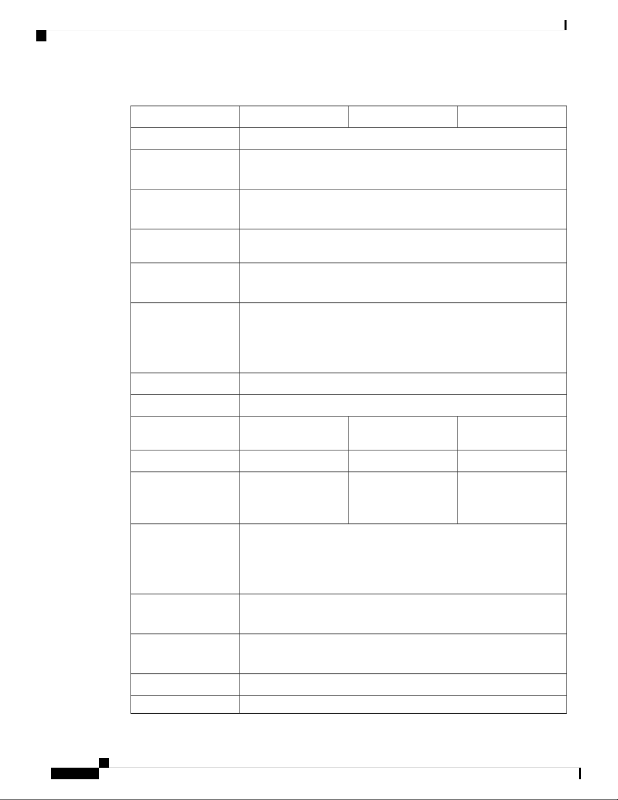
The following figure shows the package contents for the FMC 1600, 2600, and 4600. Note that the contents
are subject to change and your exact contents might contain additional or fewer items.
Figure 1: Package Contents
2Chassis1
RJ-45 to DP9-RS232 console cable (Cisco
part number 72-3383-XX)
Cisco Firepower Management Center 1600, 2600, and 4600 Hardware Installation Guide
3
Page 8
Serial Number Locations
Overview
3
800-43376-02)
5
Useful Links Cisco Firepower Management
Center 1600, 2600, and 4600
The steps in the Useful Links document
send you to the documentation you need
to install, set up, and configure your FMC.
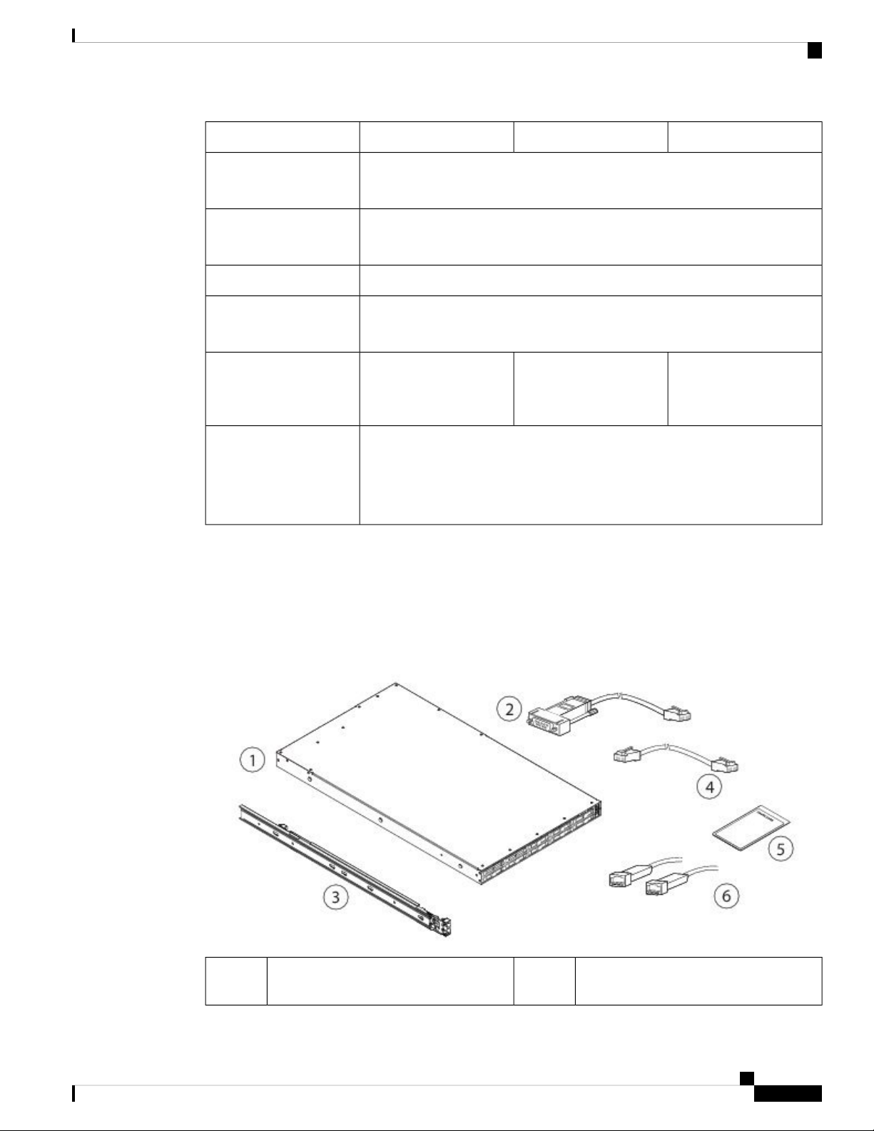
Serial Number Locations
The serial number (SN) for the FMC 1600, 2600, and 4600 is printed on the pullout asset card located on the
front panel as shown in the following figure of the FMC 1600.
Figure 2: Serial Number on Pullout Asset Card
4Cisco rail kit (Cisco part number
6
RJ-45 to RJ-45 Cat 5 Ethernet cable,
yellow six feet long (Cisco part number
72-1482-XX)
Two 10-Gb SFP transceivers with cables
Optional; in package if ordered.
4
The serial number is also on the label on the cover of the chassis as shown in the following figure.
Caution
The cover latch on the top of the chassis cover is not supported. There are no internal field-replaceable parts
in the FMC 1600, 2600, and 4600.
Cisco Firepower Management Center 1600, 2600, and 4600 Hardware Installation Guide
Page 9
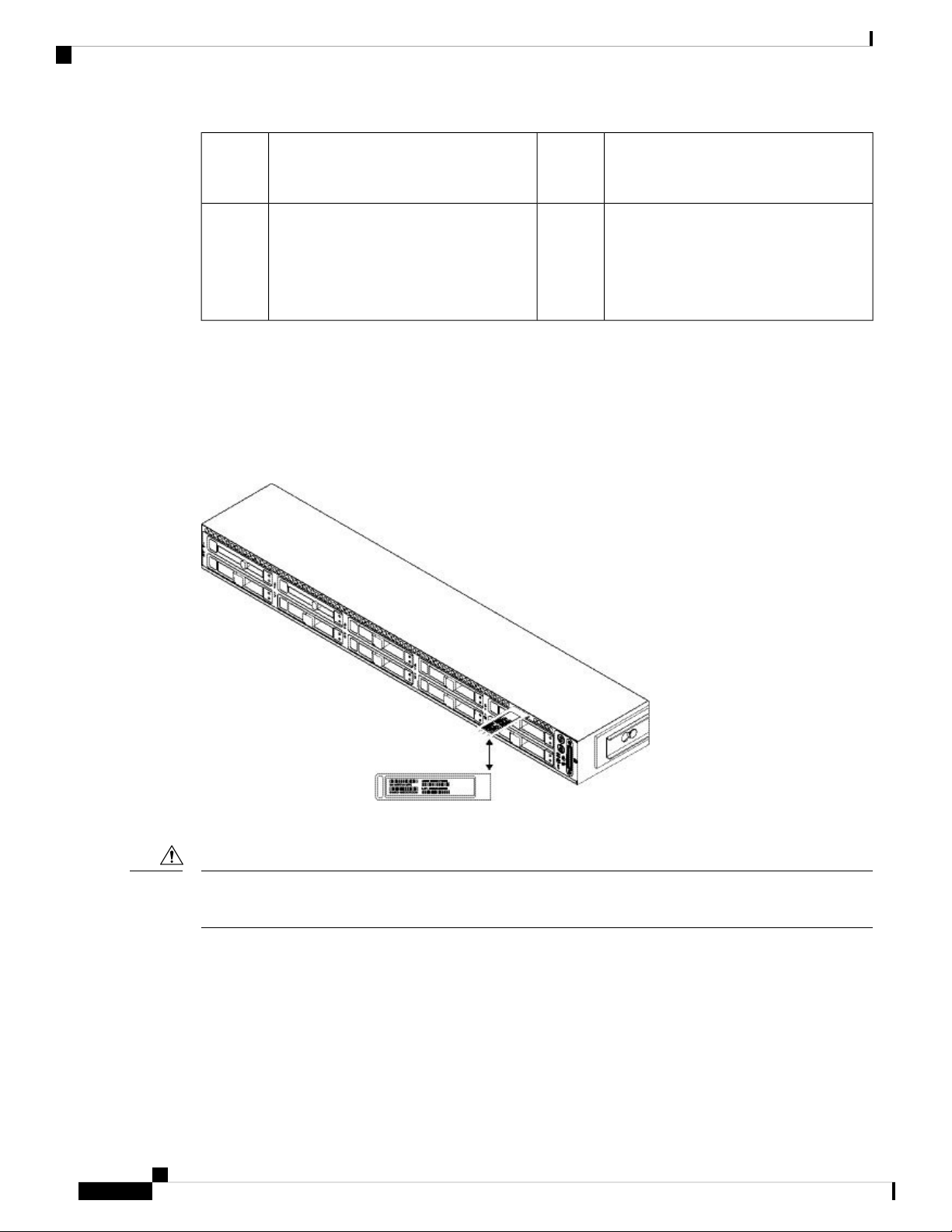
Overview
Front Panel
Figure 3: Serial Number Location on Cover
Front Panel
2Serial number label1
Cover latch
Not supported
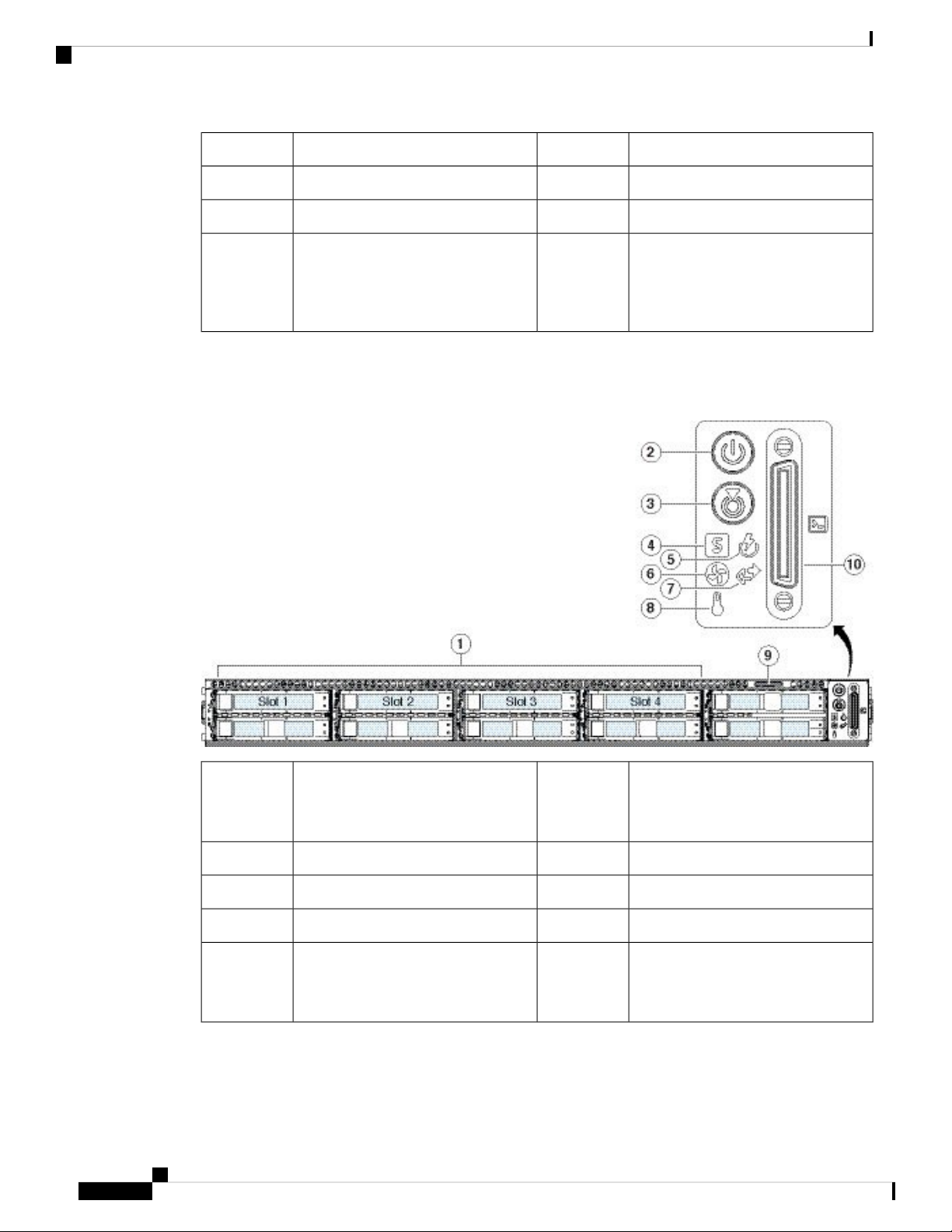
The following figure shows the front panel features and disk-drive configuration for the FMC 1600. See Front
Panel LEDs, on page 7 for a description of the LEDs.
Figure 4: FMC 1600 Front Panel
1
Power button/power status LED2Drive bays
Supports two SAS HDDs in slots 1 and
2
Cisco Firepower Management Center 1600, 2600, and 4600 Hardware Installation Guide
5
Page 10
Front Panel
Overview
System status LED4Unit identification button/LED3
Fan status LED6Power supply status LED5
Temperature status LED8Network link activity LED7
10Pullout asset card9
Keyboard, video, and mouse (KVM)
port
Not supported; use the VGA and USB
keyboard ports instead.
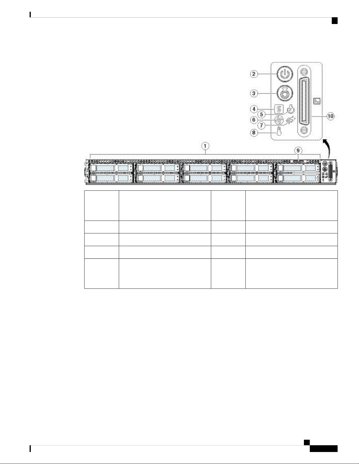
The following figure shows the front panel features and disk-drive configuration for the FMC 2600. See Front
Panel LEDs, on page 7 for a description of the LEDs.
Figure 5: FMC 2600 Front Panel
1
Power button/power status LED2Drive bays
Supports four SAS HDDs in slots 1
through 4
System status LED4Unit identification button/LED3
Fan status LED6Power supply status LED5
Temperature status LED8Network link activity LED7
10Pullout asset card9
KVM port
Not supported; use the VGA and USB
keyboard ports instead.
The following figure shows the front panel features and disk-drive configuration for the FMC 4600. See Front
Panel LEDs, on page 7 for a description of the LEDs.
Cisco Firepower Management Center 1600, 2600, and 4600 Hardware Installation Guide
6
Page 11
Overview
Front Panel LEDs
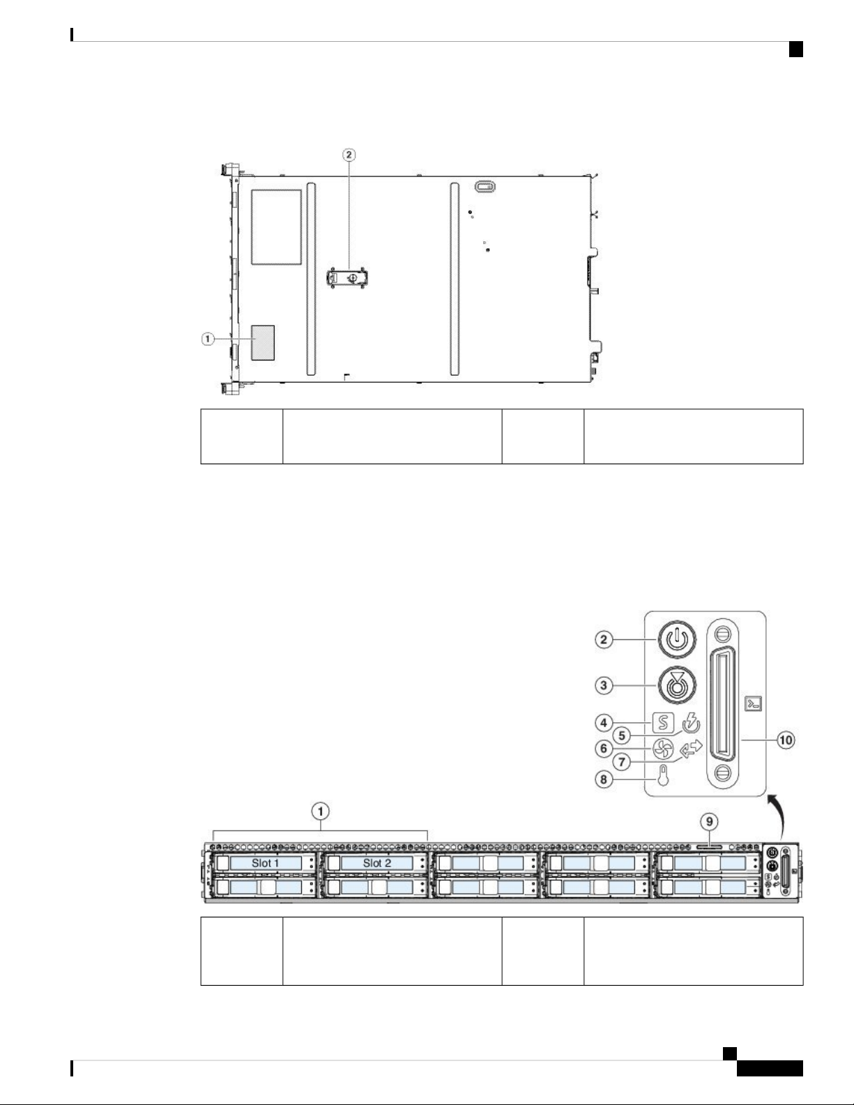
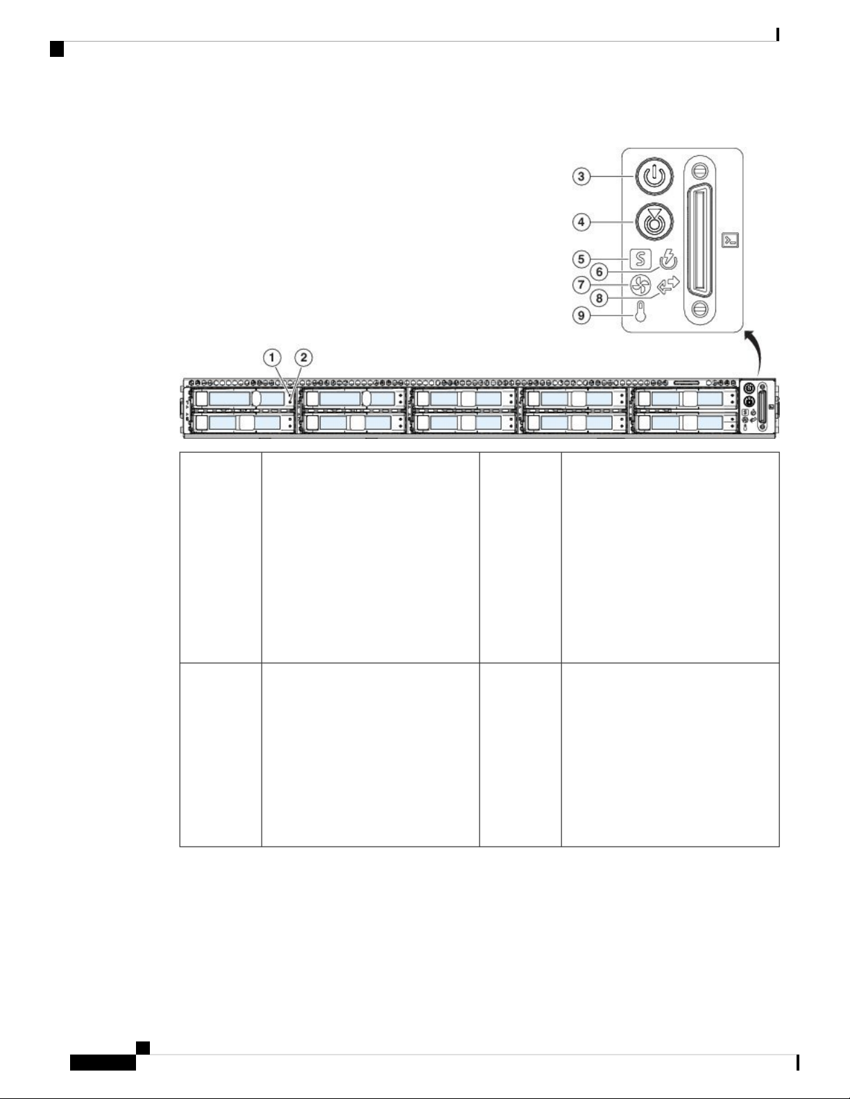
Figure 6: FMC 4600 Front Panel
1
Front Panel LEDs
The following figure shows the front panel LEDs and describes their states.
Supports ten SAS SSDs in slots 1
through 6
Power button/power status LED2Drive bays
System status LED4Unit identification button/LED3
Fan status LED6Power supply status LED5
Temperature status LED8Network link activity LED7
10Pullout asset card9
KVM port
Not supported; use the VGA and USB
keyboard ports instead.
Cisco Firepower Management Center 1600, 2600, and 4600 Hardware Installation Guide
7
Page 12
Front Panel LEDs
Overview
Figure 7: Front Panel LEDs and Their States
1
2Drive fault LED:
• Off—The drive is operating
properly.
• Amber—Drive fault detected.
• Amber, flashing—The drive is
rebuilding.
Drive activity LED:
• Off—There is no drive in the
drive tray (no access, no fault).
• Green—The drive is ready.
• Green, flashing—The drive is
reading or writing data.
• Amber, flashing with 1-second
interval—Drive locate function
activated in the software.
3
4Power LED:
• Off—There is no AC power to
the chassis.
• Amber—The chassis is in standby
mode.
• Green—The chassis is in main
Unit identification LED:
• Off—The unit identification
function is not in use.
• Blue, flashing—The unit
identification function is
activated.
power mode. Power is supplied
to all components.
Cisco Firepower Management Center 1600, 2600, and 4600 Hardware Installation Guide
8
Page 13

Overview
Front Panel LEDs
5
6System status LED:
• Green—The chassis is running in
normal operating condition.
• Green, flashing—The chassis is
performing system initialization
and memory check.
• Amber—The chassis is in a
degraded operational state (minor
fault).
Power supply status LED:
• Green—All power supplies are
operating normally.
• Amber—One or more power
supplies are in a degraded
operational state.
• Amber, flashing—One or more
power supplies are in a critical
fault state.
• Power supply redundancy is
lost.
• CPUs are mismatched.
• At least one CPU is faulty.
• At least one DIMM is faulty.
• At least one drive in a RAID
configuration failed.
• Amber, two flashes—There is a
major fault with the system board.
• Amber, three flashes—There is a
major fault with the DIMMs.
• Amber, four flashes—There is a
major fault with the CPUs.
7
8Fan status LED:
• Green—All fans are operating
properly.
• Amber, flashing—One or more
fans breached the unrecoverable
threshold.
Network link activity LED:
• Off—The Ethernet port link is
idle.
• Green—One or more Ethernet
ports are link-active, but there is
no activity.
• Green, flashing—One or more
Ethernet ports are link-active with
activity.
Cisco Firepower Management Center 1600, 2600, and 4600 Hardware Installation Guide
9
Page 14
Rear Panel
Overview
Rear Panel
Note
9
Although the Cisco Integrated Management Controller (CIMC) is not supported on the FMC, you can use
Lights-Out-Management (LOM) on the default management interface (eth0) on a Serial Over LAN (SOL)
connection to remotely monitor or manage the FMC system. For information about using LOM and SOL, see
the Cisco Firepower Management Center Getting Started Guide for Models 1600, 2600, and 4600 for more
information.
Temperature status LED:
• Green—The chassis is operating
at normal temperature.
• Amber—One or more
temperature sensors breached the
critical threshold.
• Amber, flashing—One or more
temperature sensors breached the
unrecoverable threshold.
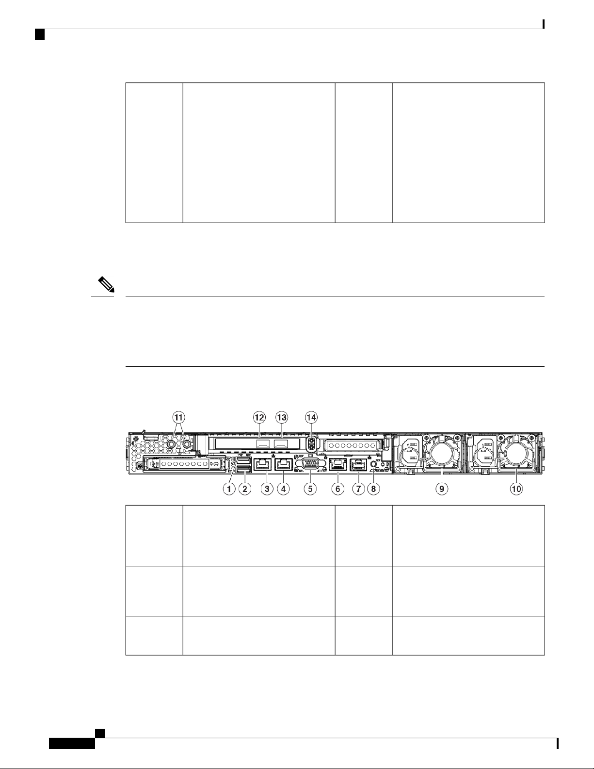
The following figure shows the rear panel of the FMC 1600, 2600, and 4600.
Figure 8: Rear Panel
1
You can connect a keyboard, and along
with a monitor on the VGA port, you
can access the console.
3
Supports 100/1000/10000 Mbps
depending on link partner capability.
2USB 3.0 Type A (USB 1)
4eth0 management interface (labeled 1)
6VGA video port (DB-15 connector)5
USB 3.0 Type A (USB 2)
You can connect a keyboard, and along
with a monitor on the VGA port, you
can access the console.
eth1 management interface (labeled 2)
Gigabit Ethernet 100/1000/10000
Mbps interface, RJ-45, LAN2
CIMC interface (labeled M)
Not supported
Cisco Firepower Management Center 1600, 2600, and 4600 Hardware Installation Guide
10
Page 15

Overview
Rear Panel LEDs
7
11
13
Rear Panel LEDs
Disabled by default; use the VGA port
and keyboard USB port instead. See
the "Set up Serial Access" topic in the
Cisco Firepower Management Center
Getting Started Guide for Models
1600, 2600, and 4600.
grounding lug
10-Gigabit Ethernet SFP+ support
Use only Cisco-supported SFP+
transceivers.
Unit identification button8Serial console port (RJ-45 connector)
770-W AC power supply (PSU 2)10770-W AC power supply (PSU 1)9
12Threaded holes for dual-hole
14eth3 management interface
eth2 management interface
10-Gigabit Ethernet SFP+ support
Use only Cisco-supported SFP+
transceivers.
Riser handle
Not in use
The following figure shows the rear panel LEDs and describes their states.
Figure 9: Rear Panel LEDs and Their States
1
link (speed on both LAN1 and LAN2):
• Off—Link speed is 100 Mbps.
• Amber—Link speed is 1 Gbps.
• Green—Link speed is 10 Gbps.
2100-Mbps/1-Gbps/10-Gbps Ethernet
100-Mbps/1-Gbps/10-Gbps Ethernet
link status (speed on both LAN1 and
LAN2):
• Off—No link is present.
• Green—Link is active.
• Green, flashing—Traffic is
present on the active link.
Cisco Firepower Management Center 1600, 2600, and 4600 Hardware Installation Guide
11
Page 16

Power Supply
Overview
3
management link:
• Off—Link speed is 10 Mbps.
• Amber—Link speed is 100 Gbps.
• Green—Link speed is 1 Gbps.
5
• Off—The unit identification
function is not in use.
• Blue, flashing—The unit
identification function is
activated.
41-Gbps Ethernet dedicated
6Rear unit identification:
1-Gbps Ethernet dedicated
management link:
• Off—No link is present.
• Amber—Link is active.
• Green, flashing—Traffic is
present on the active link.
Power supply (one LED for each
power supply):
• Off—No AC input (12-V main
power off; 12-V standby power
off)
• Green, flashing—12-V main
power off; 12-V standby power
on.
• Green—12-V main power on;
12-V standby power on.
• Amber, flashing—Warning
threshold detected but 12-V main
power on.
Power Supply
The following table lists the specifications for each 770-W AC power supply used in the FMC 1600, 2600,
and 4600.
Table 2: Power Supply Specifications
AC input voltage range
AC input frequency
• Amber—Critical error detected;
12-V main power off ( for
example, overcurrent,
overvoltage, or overtemperature
failure).
SpecificationDescription
1313 BTU/hrPower consumption
Nominal range: 100 to 120 V AC, 200 to 240 V AC
Range: 90–132 V AC, 180–264 V AC
Nominal range: 50–60 Hz
Range: 47–63 Hz
Cisco Firepower Management Center 1600, 2600, and 4600 Hardware Installation Guide
12
Page 17

Overview
Hardware Specifications
SpecificationDescription
Maximum AC input current
Efficiency rating
Hardware Specifications
9.5 A peak at 100-V AC
4.5 A peak at 208 V AC
950 VA at 100 V ACMaximum input volt amperes
770 WMaximum output power for each power supply
15 A (subcycle duration)Maximum inrush current
12 ms at 770 WMaximum hold-up time
12 V DCPower supply output voltage
12 V DCPower supply standby voltage
Climate Savers Platinum Efficiency (80 Plus Platinum
certified)
RSP2Form factor
IEC320 C13/C15Input connector
The following table lists the hardware specifications for the FMC 1600, 2600, and 4600.
Table 3: FMC 1600, 2600, and 4600 Hardware Specifications
460026001600Specification
1.7 x 16.89 x 29.8 in. (4.32 x 43.0 x 75.6 cm)Dimensions (H x W x D)
36.0 lb (17.0 kg)34.1 lb (16.8 kg)
loaded chassis)
Temperature
Relative humidity
Altitude
32.2 lb (16.6 kg)Maximum weight (fully
Operating: 50 to 95°F (10 to 35°C)
Maximum temperature is derated by 1°F/547 ft (1°C/300 m) of altitude above
3117 ft (950 m).
Nonoperating: –40 to 149°F (–40 to 65°C)
When the appliance is stored or transported.
Operating: 8 to 90% noncondensing
Nonoperating: 5 to 95% noncondensing
Operating: 0 to 10,000 ft
Nonoperating: 0 to 40,000 ft when the appliance is stored or transported
Cisco Firepower Management Center 1600, 2600, and 4600 Hardware Installation Guide
13
Page 18

Product ID Numbers
Overview
460026001600Specification
Sound power level
Sound pressure level
Product ID Numbers
The following table lists the field-replaceable PIDs associated with the FMC 1600, 2600, and 4600. The spare
components are ones that you can order and replace yourself. If any internal components fail, you must RMA
the entire chassis including the SFPs and SFP cables. Remove the drives and power supplies before you send
the chassis for RMA.
Table 4: FMC 1600, 2600, and 4600 PIDs
5.8 Bels (measure A-weighted per ISO7779 LWAd)
Operation at 73°F (23°C)
43 dBa (measure A-weighted per ISO7779 LpAM)
Operation at 73°F (23°C)
DescriptionPID
AC power supplyFMC-M5-PS-AC-770W
AC power supply (spare)FMC-M5-PS-AC-770W=
FMC 1600 and 4600 1.2-TB hard disk driveFMC-M5-HDD-1.2TB
Power Cord Specifications
Each power supply has a separate power cord. Standard power cords or jumper power cords are available for
connection to the FMC 1600, 2600, and 4600. The jumper power cords for use in racks are available as an
optional alternative to the standard power cords.
If you do not order the optional power cord with the system, you are responsible for selecting the appropriate
power cord for the product. Using a incompatible power cord with this product may result in electrical safety
hazard. Orders delivered to Argentina, Brazil, and Japan must have the appropriate power cord ordered with
the system.
Note
Only the approved power cords and jumper cords provided with the FMC 1600, 2600, and 4600 are supported.
The following power cords and jumper cords are supported.
FMC 1600 and 4600 1.2-TB hard disk drive (spare)FMC-M5-HDD-1.2TB=
FMC 2600 600-GB hard disk driveFMC-M5-HDD-600G
FMC 2600 600-GB hard disk drive (spare)FMC-M5-HDD-600G=
Rail kitUCSC-RAILB-M4
Cisco Firepower Management Center 1600, 2600, and 4600 Hardware Installation Guide
14
Page 19

Overview
Power Cord Specifications
Figure 10: Argentina CAB-250V-10A-AR
Cord set rating: 10 A, 250 V2Plug: IRAM 20731
Connector: IEC 60320/C133
Figure 11: Australia CAB-9K10A-AU
Connector: IEC 60320/C153
Figure 12: Brazil PWR-250V-10A-BZ
Connector: IEC 60320/C133
Cord set rating: 10 A, 250 V2Plug: A.S. 3112-20001
Cord set rating: 10 A, 250 V2Plug: NBR 141361
Cisco Firepower Management Center 1600, 2600, and 4600 Hardware Installation Guide
15
Page 20

Power Cord Specifications
Figure 13: Cabinet Jumper CAB-C13-C14-2M
Figure 14: Cabinet Jumper CAB-C13-C14-AC
Overview
Cord set rating: 10A, 250V2Plug: SS10A1
Connector: HS10S, C-13 to C-143
3
Connector: HS10S, C-13 to C-14 (recessed
receptacle)
Figure 15: Cabinet Jumper CAB-C13-CBN
Connector: HS10S, C-13 to C-143
Cord set rating: 10 A, 250 V2Plug: SS10A1
Cord set rating: 10 A, 250 V2Plug: SS10A1
Cisco Firepower Management Center 1600, 2600, and 4600 Hardware Installation Guide
16
Page 21

Overview
Power Cord Specifications
Figure 16: China CAB-250V-10A-CH
Cord set rating: 10 A, 250 V2Plug: GB2099.1/20081
Connector: IEC 60320/C133
Figure 17: Europe CAB-9K10A-EU
Connector: IEC 60320/C15 (VSCC 15)3
Figure 18: India CAB-250V-10A-ID
Connector: IEC 60320-C133
Cord set rating: 10 A/16 A, 250 V2Plug: CEE 7/7 (M2511)1
Cord set rating: 16 A, 250 V2Plug: IS 6538-19711
Cisco Firepower Management Center 1600, 2600, and 4600 Hardware Installation Guide
17
Page 22

Power Cord Specifications
Figure 19: Israel CAB-250V-10A-IS
Figure 20: Italy CAB-9K10A-IT
Overview
Cord set rating: 10 A, 250 V2Plug: SI-321
Connector: IEC 60320-C133
3
Connector: IEC 60320/C15
(EN 60320/C15M)
Figure 21: Japan CAB-JPN-3PIN
Connector: IEC 60320/C133
Cord set rating: 10 A, 250 V2Plug: CEI 23-16/VII (I/3G)1
Cord set rating: 12 A, 125 V2Plug: JIS 83031
Cisco Firepower Management Center 1600, 2600, and 4600 Hardware Installation Guide
18
Page 23

Overview
Power Cord Specifications
Figure 22: Japan CAB-C13-C14-2M-JP
Cord set rating: 10 A, 250 V2Plug: EN 60320-2-2/E1
Connector: EN 60320/C13 to C143
Figure 23: Korea CAB-9K10S-KOR
Connector: IEC 60320/C153
Figure 24: North America CAB-9K12A-NA
Connector: IEC 60320/C153
Cord set rating: 10 A, 250 V2Plug: EL211 (KSC 8305)1
Cord set rating: 13 A, 125 V2Plug: NEMA5-15P1
Cisco Firepower Management Center 1600, 2600, and 4600 Hardware Installation Guide
19
Page 24

Power Cord Specifications
Figure 25: North America CAB-N5K6A-NA
Figure 26: North America CAB-AC-L620-C13
Overview
Cord set rating: 10 A, 125 V2Plug: NEMA6-15P1
Connector: IEC 60320/C133
Connector: IEC 60320/C133
Figure 27: Switzerland CAB-9K10A-SW
Connector: IEC 60320/C153
Cord set rating: 13 A, 250 V2Plug: NEMA L6-20 (molded twist lock)1
Cord set rating: 10 A, 250 V2Plug: SEV 1011 (MP232-R)1
Cisco Firepower Management Center 1600, 2600, and 4600 Hardware Installation Guide
20
Page 25

Overview
Power Cord Specifications
Figure 28: Taiwan CAB-ACTW
Cord set rating: 10 A, 125 V2Plug: EL 302 (CNS10917)1
Connector: IEC 60320/C133
Figure 29: United Kingdom CAB-9K10A-UK
Cord set rating: 10 A, 250 V2Plug: BS1363A/SS1451
Connector: IEC 60320/C153
Cisco Firepower Management Center 1600, 2600, and 4600 Hardware Installation Guide
21
Page 26

Power Cord Specifications
Overview
Cisco Firepower Management Center 1600, 2600, and 4600 Hardware Installation Guide
22
Page 27

Installation Preparation
• Installation Warnings, on page 23
• Safety Recommendations, on page 25
• Maintain Safety with Electricity, on page 25
• Prevent ESD Damage, on page 26
• Site Environment, on page 26
• Power Supply Considerations, on page 26
• Rack Configuration Considerations, on page 27
Installation Warnings
Be sure to read the REGULATORY & COMPLIANCE SAFETY INFORMATION document before installing
the Firepower Management Center management appliance.
CHAPTER 2
Caution
Warning
Warning
Do NOT open the appliance except under direction from TAC.
Take note of the following warnings:
Statement 1071—Warning Definition
IMPORTANT SAFETY INSTRUCTIONS
This warning symbol means danger. You are in a situation that could cause bodily injury. Before you work
on any equipment, be aware of the hazards involved with electrical circuitry and be familiar with standard
practices for preventing accidents. Use the statement number provided at the end of each warning to locate
its translation in the translated safety warnings that accompanied this device.
SAVE THESE INSTRUCTIONS
Statement 1005—Circuit Breaker
This product relies on the building’s installation for short-circuit (overcurrent) protection. Ensure that the
protective device is rated not greater than: USA: 120 V, 15 A (EU: 250 V, 16 A)
Cisco Firepower Management Center 1600, 2600, and 4600 Hardware Installation Guide
23
Page 28

Installation Warnings
Installation Preparation
Warning
Warning
Warning
Warning
Statement 1004—Installation Instructions
Read the installation instructions before using, installing or connecting the system to the power source.
Statement 12—Power Supply Disconnection Warning
Before working on a chassis or working near power supplies, unplug the power cord on AC units; disconnect
the power at the circuit breaker on DC units.
Statement 43—Jewelry Removal Warning
Before working on equipment that is connected to power lines, remove jewelry (including rings, necklaces,
and watches). Metal objects will heat up when connected to power and ground and can cause serious burns
or weld the metal object to the terminals.
Statement 94—Wrist Strap Warning
During this procedure, wear grounding wrist straps to avoid ESD damage to the card. Do not directly touch
the backplane with your hand or any metal tool, or you could shock yourself.
Warning
Warning
Warning
Statement 1045—Short-Circuit Protection
This product requires short-circuit (overcurrent) protection to be provided as part of the building installation.
Install only in accordance with national and local wiring regulations.
Statement 1021—SELV Circuit
To avoid electric shock, do not connect safety extra-low voltage (SELV) circuits to telephone-network voltage
(TNV) circuits. LAN ports contain SELV circuits, and WAN ports contain TNV circuits. Some LAN and
WAN ports both use RJ-45 connectors. Use caution when connecting cables.
Statement 1024—Ground Conductor
This equipment must be grounded. Never defeat the ground conductor or operate the equipment in the absence
of a suitably installed ground conductor. Contact the appropriate electrical inspection authority or an electrician
if you are uncertain that suitable grounding is available.
Cisco Firepower Management Center 1600, 2600, and 4600 Hardware Installation Guide
24
Page 29

Installation Preparation
Safety Recommendations
Warning
Warning
Warning
Statement 1040—Product Disposal
Ultimate disposal of this product should be handled according to all national laws and regulations.
Statement 1074—Comply with Local and National Electrical Codes
To reduce risk of electric shock or fire, installation of the equipment must comply with local and national
electrical codes.
Statement 19—TN Power Warning
The device is designed to work with TN power systems.
Safety Recommendations
Observe these safety guidelines:
• Keep the area clear and dust free before, during, and after installation.
• Keep tools away from walkways, where you and others might trip over them.
• Do not wear loose clothing or jewelry, such as earrings, bracelets, or chains that could get caught in the
chassis.
• Wear safety glasses if you are working under any conditions that might be hazardous to your eyes.
• Do not perform any action that creates a potential hazard to people or makes the equipment unsafe.
• Never attempt to lift an object that is too heavy for one person.
Maintain Safety with Electricity
Warning
Before working on a chassis, be sure the power cord is unplugged.
Be sure to read the REGULATORY & COMPLIANCE SAFETY INFORMATION document before installing
the chassis.
Follow these guidelines when working on equipment powered by electricity:
• Before beginning procedures that require access to the interior of the chassis, locate the emergency
power-off switch for the room in which you are working. Then, if an electrical accident occurs, you can
act quickly to turn off the power.
• Do not work alone if potentially hazardous conditions exist anywhere in your work space.
Cisco Firepower Management Center 1600, 2600, and 4600 Hardware Installation Guide
25
Page 30

Prevent ESD Damage
Installation Preparation
• Never assume that power is disconnected; always check.
• Look carefully for possible hazards in your work area, such as moist floors, ungrounded power extension
cables, frayed power cords, and missing safety grounds.
• If an electrical accident occurs:
• Use caution; do not become a victim yourself.
• Disconnect power from the system.
• If possible, send another person to get medical aid. Otherwise, assess the condition of the victim,
and then call for help.
• Determine whether the person needs rescue breathing or external cardiac compressions; then take
appropriate action.
• Use the chassis within its marked electrical ratings and product usage instructions.
• The chassis is equipped with an AC-input power supply, which is shipped with a three-wire electrical
cord with a grounding-type plug that fits into a grounding-type power outlet only. Do not circumvent
this safety feature. Equipment grounding should comply with local and national electrical codes.
Prevent ESD Damage
ESD occurs when electronic components are improperly handled, and it can damage equipment and impair
electrical circuitry, which can result in intermittent or complete failure of your equipment.
Always follow ESD-prevention procedures when removing and replacing components. Ensure that the chassis
is electrically connected to an earth ground. Wear an ESD-preventive wrist strap, ensuring that it makes good
skin contact. Connect the grounding clip to an unpainted surface of the chassis frame to safely ground ESD
voltages. To properly guard against ESD damage and shocks, the wrist strap and cord must operate effectively.
If no wrist strap is available, ground yourself by touching the metal part of the chassis.
For safety, periodically check the resistance value of the antistatic strap, which should be between one and
10 megohms.
Site Environment
See Hardware Specifications, on page 13 for information about physical specifications.
To avoid equipment failures and reduce the possibility of environmentally caused shutdowns, plan the site
layout and equipment locations carefully. If you are currently experiencing shutdowns or unusually high error
rates with your existing equipment, these considerations may help you isolate the cause of failures and prevent
future problems.
Power Supply Considerations
See Power Supply, on page 12 for more detailed information about the power supply in the chassis.
When installing the chassis, consider the following:
Cisco Firepower Management Center 1600, 2600, and 4600 Hardware Installation Guide
26
Page 31

Installation Preparation
• Check the power at the site before installing the chassis to ensure that it is free of spikes and noise. Install
a power conditioner, if necessary, to ensure proper voltages and power levels in the appliance-input
voltage.
• Install proper grounding for the site to avoid damage from lightning and power surges.
• The chassis does not have a user-selectable operating range. Refer to the label on the chassis for the
correct appliance input-power requirement.
• Several styles of AC-input power supply cords are available for the chassis; make sure that you have the
correct style for your site.
• If you are using dual redundant (1+1) power supplies, we recommend that you use independent electrical
circuits for each power supply.
• Install an uninterruptible power source for your site, if possible.
Rack Configuration Considerations
Rack Configuration Considerations
See Rack-Mount the Chassis, on page 29 for the procedure for rack-mounting the chassis.
Consider the following when planning a rack configuration:
• If you are mounting a chassis in an open rack, make sure that the rack frame does not block the intake
or exhaust ports.
• Be sure enclosed racks have adequate ventilation. Make sure that the rack is not overly congested as each
chassis generates heat. An enclosed rack should have louvered sides and a fan to provide cooling air.
• In an enclosed rack with a ventilation fan in the top, heat generated by equipment near the bottom of the
rack can be drawn upward and into the intake ports of the equipment above it in the rack. Ensure that
you provide adequate ventilation for equipment at the bottom of the rack.
• Baffles can help to isolate exhaust air from intake air, which also helps to draw cooling air through the
chassis. The best placement of the baffles depends on the airflow patterns in the rack. Experiment with
different arrangements to position the baffles effectively.
Cisco Firepower Management Center 1600, 2600, and 4600 Hardware Installation Guide
27
Page 32

Rack Configuration Considerations
Installation Preparation
Cisco Firepower Management Center 1600, 2600, and 4600 Hardware Installation Guide
28
Page 33

CHAPTER 3
Mount and Connect
• Unpack and Inspect the Chassis, on page 29
• Rack-Mount the Chassis, on page 29
• Connect Cables, Turn on Power, and Verify Connectivity, on page 32
Unpack and Inspect the Chassis
Note
The chassis is thoroughly inspected before shipment. If any damage occurred during transportation or any
items are missing, contact your customer service representative immediately. Keep the shipping container in
case you need to send the chassis back due to damage.
See Package Contents, on page 3 for a list of what shipped with the chassis.
Step 1 Remove the chassis from its cardboard container and save all packaging material.
Step 2 Compare the shipment to the equipment list provided by your customer service representative. Verify that you have all
items.
Step 3 Check for damage and report any discrepancies or damage to your customer service representative. Have the following
information ready:
• Invoice number of shipper (see the packing slip)
• Model and serial number of the damaged unit
• Description of damage
• Effect of damage on the installation
Rack-Mount the Chassis
You can install the chassis in a rack using the Cisco rack kit.
Cisco Firepower Management Center 1600, 2600, and 4600 Hardware Installation Guide
29
Page 34

Rack-Mount the Chassis
Note
Mount and Connect
The rack must be of the following type:
• A standard 19-in. (48.3-cm) wide, 4-post EIA rack with mounting posts that conform to English universal
hole spacing per section 1 of ANSI/EIA-310-D-1992.
• The rack post holes can be square 0.38-in. (9.6 mm), round 0.28-in. (7.1 mm), #12-24 UNC, or #10-32
UNC when you use the supplied slide rails.
• The minimum vertical rack space per chassis must be 1 RU, equal to 1.75 in. (44.45 mm).
• The slide rails for the chassis have an adjustment range of 24 to 36 in. (610 to 914 mm).
The slide rails supplied by Cisco Systems for the chassis do not require tools for installation if you install
them in a rack that has square 0.38-in. (9.6 mm), round 0.28-in. (7.1 mm), or #12-24 UNC threaded holes.
Before you begin
Take note of the following warning:
Warning
Statement 1006—Chassis Warning for Rack-Mounting and Servicing
To prevent bodily injury when mounting or servicing this unit in a rack, you must take special precautions to
ensure that the system remains stable. The following guidelines are provided to ensure your safety:
• This unit should be mounted at the bottom of the rack if it is the only unit in the rack.
• When mounting this unit in a partially filled rack, load the rack from the bottom to the top with the
heaviest component at the bottom of the rack.
• If the rack is provided with stabilizing devices, install the stabilizers before mounting or servicing the
unit in the rack.
Step 1 Attach the inner rails to the sides of the chassis:
a) Align an inner rail with one side of the chassis so that the three keyed slots in the rail align with the three pegs on the
side of the chassis.
b) Set the keyed slots over the pegs, and then slide the rail toward the front to lock it in place on the pegs. The front slot
has a metal clip that locks over the front peg.
c) Install the second inner rail to the opposite side of the chassis.
Figure 30: Attach the Inner Rail to Side of Chassis
Cisco Firepower Management Center 1600, 2600, and 4600 Hardware Installation Guide
30
Page 35

Mount and Connect
Rack-Mount the Chassis
Locking clip on inner rail2Front of chassis1
Step 2 Open the front securing plate on both slide-rail assemblies. The front end of the slide-rail assembly has a spring-loaded
securing plate that must be open before you can insert the mounting pegs into the rack-post holes.
On the outside of the assembly, push the green arrow button toward the rear to open the securing plate.
Figure 31: Front Securing Mechanism, Inside of Front End
3
Securing plate shown pulled back to open
position
Step 3 Install the slide rails into the rack:
a) Align one slide-rail assembly front end with the front rack-post holes that you want to use.
The slide rail front end wraps around the outside of the rack post and the mounting pegs enter the rack-post holes
from the outside-front.
Note
The rack post must be between the mounting pegs and the open securing plate.
b) Push the mounting pegs into the rack-post holes from the outside-front.
c) Press the securing plate release button, marked “PUSH.” The spring-loaded securing plate closes to lock the pegs in
place.
d) Attach the second slide-rail assembly to the opposite side of the rack. Make sure that the two slide-rail assemblies
are at the same height with each other and are level front-to-back.
e) Pull the inner slide rails on each assembly out toward the rack front until they hit the internal stops and lock in place.
Step 4 Insert the chassis into the slide rails:
a) Align the rear of the inner rails that are attached to the chassis sides with the front ends of the empty slide rails on
the rack.
b) Push the inner rails into the slide rails on the rack until they stop at the internal stops.
c) Slide the release clip toward the rear on both inner rails, and then continue pushing the chassis into the rack until its
front slam latches engage with the rack posts
Rack post2Front mounting pegs1
Cisco Firepower Management Center 1600, 2600, and 4600 Hardware Installation Guide
31
Page 36

Connect Cables, Turn on Power, and Verify Connectivity
Figure 32: Inner Rail Release Clip
Mount and Connect
2Inner rail release clip1
Inner rail attached to the chassis and inserted
into outer rail
3
Outer rail attached to rack post4Button to unlock rail
Press this button to unlock the rail so you can
pull out the chassis from the rack when
uninstalling or performing maintenance.
Step 5 (Optional) Secure the chassis in the rack more permanently by using the two screws that are provided with the slide rails.
Perform this step if you plan to move the rack with chassis installed. With the chassis fully pushed into the slide rails,
open a hinged slam latch lever on the front of the chassis and insert the screw through the hole that is under the lever.
The screw threads into the static part of the rail on the rack post and prevents the chassis from being pulled out. Repeat
for the opposite slam latch.
What to do next
Continue with Connect Cables, Turn on Power, and Verify Connectivity, on page 32.
Connect Cables, Turn on Power, and Verify Connectivity
This procedure references the rear panel ports of the FMC 2600 and 4600. The FMC 1600 is the same except
that it does not have the two 10-G SFP+ ports above the Ethernet ports.
After rack mounting the chassis, follow these steps to connect cables, turn on power, and verify connectivity.
Note
AC power supplies have internal grounding and so no additional chassis grounding is required when the
supported AC power cords are used. For more information about supported power cords, see Power Cord
Specifications, on page 14.
Note
Although the CIMC is not supported on the FMC, you can use LOM on the default management interface
(eth0) on a SOL connection to remotely monitor or manage the FMC system. For information about using
LOM and SOL, see the Cisco Firepower Management Center Getting Started Guide for Models 1600, 2600,
and 4600 for your model.
Cisco Firepower Management Center 1600, 2600, and 4600 Hardware Installation Guide
32
Page 37

Mount and Connect
Connect Cables, Turn on Power, and Verify Connectivity
Before you begin
Take note of the following warnings.
Warning
Statement 1009—Laser Radiation
Laser radiation is present when the system is open.
Warning
Statement 1014—Laser Radiation
Laser radiation is present when the system is open and interlocks bypassed.
Warning
Statement 1051—Laser Radiation
Invisible laser radiation may be emitted from disconnected fibers or connectors. Do not stare into beams or
view directly with optical instruments.
Warning
Statement 1053—Class 1M Laser Radiation
Class 1M laser radiation when open. Do not view directly with optical instruments.
Step 1 (Optional) VGA port and USB port—Connect a monitor to the VGA port and a keyboard to the USB port to complete
initial setup at the CLI. You can alternatively complete initial setup using HTTPS on eth0 (see Step 2).
Note
Figure 33: Cable Connections
The serial console port is not enabled for initial setup.
1
10 Gigabit Ethernet SFP+ support
Use only Cisco supported SFP+s
transceivers.
2eth2 management interface
eth3 management interface
10 Gigabit Ethernet SFP+ support
Use only Cisco supported SFP+s
transceivers.
Cisco Firepower Management Center 1600, 2600, and 4600 Hardware Installation Guide
33
Page 38

Connect Cables, Turn on Power, and Verify Connectivity
Mount and Connect
3
4Two USB 3.0 Type A ports
You can connect a keyboard, and along
with a monitor on the VGA port, you can
access the console.
5
6eth1 management interface (named 2)
Gigabit Ethernet 100/1000/10000 Mbps
interface, RJ-45
7
Serial console port
eth0 management interface (named 1)
Gigabit Ethernet 100/1000/10000 Mbps
interface, RJ-45
eth0 is the default management interface.
VGA video port (DB-15 connector)
This port is disabled by default; use the
VGA port and keyboard USB port instead.
Use the console cable (RJ-45 to DB-9) to
connect a computer to the FMC.
Step 2 eth0 management interface (named 1)—Use this interface to perform initial setup using HTTPS, to perform routine
management, and to manage devices from the FMC chassis. Using an Ethernet cable, connect the eth0 interface to your
default management network reachable from your management PC. This interface is the default management interface
and is enabled by default.
Note
You must perform initial setup to change the eth0 IP address to match your network. You can use the
VGA/keyboard CLI for initial setup to set the eth0 IP address, or you can connect your computer directly to
eth0, change the address using the HTTPS initial setup, and then connect eth0 to your network.
Step 3 (Optional) eth1 management interface (named 6)—Connect this management interface to the same or different network
from your other management interfaces depending on your network needs. For information about management interfaces
and network topology, see the Firepower Management Center Configuration Guide for your version.
Step 4 eth2 and eth3 management interfaces—If your model includes 10-Gigabit Ethernet SFP+ interfaces, install any
Cisco-supported SFP+ transceivers and cables as needed. You can connect these interfaces to the same or different network
from your other management interfaces depending on your network needs. For more information about management
interfaces and network topology, see the Firepower Management Center Configuration Guide for your version.
Each Cisco-certified SFP+ transceiver (SFP-10G-SR) has an internal serial EEPROM that is encoded with security
information. This encoding allows us to identify and validate that the SFP transceiver meets the requirements for the
FMC chassis.
Note
Only Cisco certified SFP+ transceivers are compatible with the 10-G interfaces. Cisco TAC may refuse support
for any interoperability problems that result from using an untested third-party SFP transceiver.
Step 5 Power—Use one of the supported power cords to connect the power supplies of the chassis to your power source. For
more information about supported power cords, see Power Cord Specifications, on page 14.
Step 6 Verify—Press the Power button on the front of the chassis, and verify that the power status LED is on.
Step 7 Setup and configuration—See the Cisco Firepower Management Center Getting Started Guide for Models 1600, 2600,
and 4600 to continue setup and configuration.
Cisco Firepower Management Center 1600, 2600, and 4600 Hardware Installation Guide
34
Page 39

Maintenance and Upgrade
• Power Button Shutdown, on page 35
• Remove and Replace a Drive, on page 36
• Remove and Replace a Power Supply, on page 38
Power Button Shutdown
The FMC runs in two modes:
• Main power mode—Power is supplied to all FMC components and all operating systems can run.
• Standby power mode—Power is supplied only to the service processor and certain components. You can
safely remove power cords from the FMC in this mode.
CHAPTER 4
Caution
Step 1 Check the Power LED:
• Amber—The FMC is already in standby mode and you can safely remove power.
• Green—The FMC is in main power mode and you must shut it down before you can safely remove power.
Step 2 Perform a graceful shutdown or a hard shutdown:
Caution
• Graceful shutdown—Press and release the Power button. The operating system performs a graceful shutdown and
After you shut down the FMC to standby power, electric current is still present in the chassis. To completely
remove power as directed in some maintenance procedures, you must disconnect all power cords from all
power supplies on the FMC.
You can shut down the FMC using the front panel Power button or software management. See the system
shutdown procedure in the Firepower Management Center Configuration Guide for your version for the
software procedures.
To avoid data loss or damage to your operating system, perform a graceful shutdown of the operating system.
the FMC goes into standby mode. The power LED is amber.
Cisco Firepower Management Center 1600, 2600, and 4600 Hardware Installation Guide
35
Page 40

Remove and Replace a Drive
• Emergency shutdown—Press and hold the Power button for four seconds to force the main power off and immediately
enter standby mode.
Remove and Replace a Drive
Note
The drives are hot-swappable. You do not have to shut down the FMC to remove or replace drives.
Note
You cannot add more drives to your FMC. You can only replace the drives in the slots that are supported for
your model.
Maintenance and Upgrade
Warning
Warning
Warning
Warning
Before you begin
Statement 1018—Supply Circuit
To reduce risk of electric shock and fire, take care when connecting units to the supply circuit so that wiring
is not overloaded.
Statement 1019—Main Disconnecting Device
The plug-socket combination must be accessible at all times, because it serves as the main disconnecting
device.
Statement 1024—Ground Conductor
This equipment must be grounded. Never defeat the ground conductor or operate the equipment in the absence
of a suitably installed ground conductor. Contact the appropriate electrical inspection authority or an electrician
if you are uncertain that suitable grounding is available.
Statement 1030—Equipment Installation
36
Only trained and qualified personnel should be allowed to install, replace, or service this equipment.
Warning
Statement 1073—No User-Serviceable Parts
No serviceable parts inside. To avoid risk of electric shock, do not open.
Cisco Firepower Management Center 1600, 2600, and 4600 Hardware Installation Guide
Page 41

Maintenance and Upgrade
Remove and Replace a Drive
Warning
Statement 1074—Comply with Local and National Electrical Codes
To reduce risk of electric shock or fire, installation of the equipment must comply with local and national
electrical codes.
Step 1 Remove the drive that you are replacing:
a) Press the release button on the face of the drive tray.
b) Grasp and open the ejector lever and then pull the drive tray out of the slot.
Figure 34: Remove the Drive
Release button2Ejector handle1
Step 2 Remove the four drive-tray screws that secure the drive to the tray and then lift the drive out of the tray.
Cisco Firepower Management Center 1600, 2600, and 4600 Hardware Installation Guide
37
Page 42

Remove and Replace a Power Supply
Figure 35: Remove the Drive Tray
Maintenance and Upgrade
Step 3 Install a new drive:
a) Place a new drive in the empty drive tray and install the four drive-tray screws.
b) With the ejector lever on the drive tray open, insert the drive tray into the empty drive bay.
c) Push the tray into the slot until it touches the backplane, and then close the ejector lever to lock the drive in place.
Remove and Replace a Power Supply
The FMC ships with two power supplies, which are redundant and hot-swappable. One is the active power
supply and the other is the standby power supply (1+1).
This FMC also supports cold redundancy. Depending on the power being drawn by the FMC, one power
supply might actively provide all power to the system while the remaining power supply is put into a standby
state. For example, if the power consumption can be satisfied by power supply 1, then power supply 2 is put
into a standby state.
Caution
When you replace power supplies, do not mix power supply types in the FMC. Both power supplies must be
the same wattage and Cisco PID.
Drive removed from drive tray2Drive tray screws ( two on each side)1
Cisco Firepower Management Center 1600, 2600, and 4600 Hardware Installation Guide
38
Page 43

Maintenance and Upgrade
Remove and Replace a Power Supply
Trouble
Warning
Warning
Warning
Power supply health monitoring notifies you if the power supply loses power or malfunctions so that redundancy
is lost. Check the power supply cables to make sure they are functioning. If they are and errors are still
occurring, replace the power supply.
Before you begin
Take note of the following warnings:
Statement 1018—Supply Circuit
To reduce risk of electric shock and fire, take care when connecting units to the supply circuit so that wiring
is not overloaded.
Statement 1019—Main Disconnecting Device
The plug-socket combination must be accessible at all times, because it serves as the main disconnecting
device.
Statement 1024—Ground Conductor
This equipment must be grounded. Never defeat the ground conductor or operate the equipment in the absence
of a suitably installed ground conductor. Contact the appropriate electrical inspection authority or an electrician
if you are uncertain that suitable grounding is available.
Warning
Statement 1030—Equipment Installation
Only trained and qualified personnel should be allowed to install, replace, or service this equipment.
Warning
Statement 1073—No User-Serviceable Parts
No serviceable parts inside. To avoid risk of electric shock, do not open.
Warning
Statement 1074—Comply with Local and National Electrical Codes
To reduce risk of electric shock or fire, installation of the equipment must comply with local and national
electrical codes.
Step 1 Remove the power supply:
Cisco Firepower Management Center 1600, 2600, and 4600 Hardware Installation Guide
39
Page 44

Remove and Replace a Power Supply
a) Grasp the power supply handle while pinching the release lever toward the handle.
b) Pull the power supply out of the bay.
Figure 36: Remove and Replace the AC Power Supply
Maintenance and Upgrade
Step 2 Install a new power supply:
a) Grasp the power supply handle and insert the new power supply into the empty bay.
b) Push the power supply into the bay until the release lever locks.
c) Connect the power cord to the new power supply.
d) If you shut down the FMC, press the Power button to return it to main power mode.
Handle2Release lever1
Cisco Firepower Management Center 1600, 2600, and 4600 Hardware Installation Guide
40
 Loading...