

Cisco Firepower 2100 Series, Firepower 2110, Firepower 2120, Firepower 2130, Firepower 2140 Hardware Installation Manual
Page 1

Cisco Firepower 2100 Series Hardware Installation Guide
First Published: 2017-05-25
Last Modified: 2018-12-07
Americas Headquarters
Cisco Systems, Inc.
170 West Tasman Drive
San Jose, CA 95134-1706
USA
http://www.cisco.com
Tel: 408 526-4000
800 553-NETS (6387)
Fax: 408 527-0883
Page 2

THE SPECIFICATIONS AND INFORMATION REGARDING THE PRODUCTS IN THIS MANUAL ARE SUBJECT TO CHANGE WITHOUT NOTICE. ALL STATEMENTS,
INFORMATION, AND RECOMMENDATIONS IN THIS MANUAL ARE BELIEVED TO BE ACCURATE BUT ARE PRESENTED WITHOUT WARRANTY OF ANY KIND,
EXPRESS OR IMPLIED. USERS MUST TAKE FULL RESPONSIBILITY FOR THEIR APPLICATION OF ANY PRODUCTS.
THE SOFTWARE LICENSE AND LIMITED WARRANTY FOR THE ACCOMPANYING PRODUCT ARE SET FORTH IN THE INFORMATION PACKET THAT SHIPPED WITH
THE PRODUCT AND ARE INCORPORATED HEREIN BY THIS REFERENCE. IF YOU ARE UNABLE TO LOCATE THE SOFTWARE LICENSE OR LIMITED WARRANTY,
CONTACT YOUR CISCO REPRESENTATIVE FOR A COPY.
The Cisco implementation of TCP header compression is an adaptation of a program developed by the University of California, Berkeley (UCB) as part of UCB's public domain version of
the UNIX operating system. All rights reserved. Copyright©1981, Regents of the University of California.
NOTWITHSTANDING ANY OTHER WARRANTY HEREIN, ALL DOCUMENT FILES AND SOFTWARE OF THESE SUPPLIERS ARE PROVIDED “AS IS" WITH ALL FAULTS.
CISCO AND THE ABOVE-NAMED SUPPLIERS DISCLAIM ALL WARRANTIES, EXPRESSED OR IMPLIED, INCLUDING, WITHOUT LIMITATION, THOSE OF
MERCHANTABILITY, FITNESS FOR A PARTICULAR PURPOSE AND NONINFRINGEMENT OR ARISING FROM A COURSE OF DEALING, USAGE, OR TRADE PRACTICE.
IN NO EVENT SHALL CISCO OR ITS SUPPLIERS BE LIABLE FOR ANY INDIRECT, SPECIAL, CONSEQUENTIAL, OR INCIDENTAL DAMAGES, INCLUDING, WITHOUT
LIMITATION, LOST PROFITS OR LOSS OR DAMAGE TO DATA ARISING OUT OF THE USE OR INABILITY TO USE THIS MANUAL, EVEN IF CISCO OR ITS SUPPLIERS
HAVE BEEN ADVISED OF THE POSSIBILITY OF SUCH DAMAGES.
Any Internet Protocol (IP) addresses and phone numbers used in this document are not intended to be actual addresses and phone numbers. Any examples, command display output, network
topology diagrams, and other figures included in the document are shown for illustrative purposes only. Any use of actual IP addresses or phone numbers in illustrative content is unintentional
and coincidental.
All printed copies and duplicate soft copies of this document are considered uncontrolled. See the current online version for the latest version.
Cisco has more than 200 offices worldwide. Addresses and phone numbers are listed on the Cisco website at www.cisco.com/go/offices.
Cisco and the Cisco logo are trademarks or registered trademarks of Cisco and/or its affiliates in the U.S. and other countries. To view a list of Cisco trademarks, go to this URL: www.cisco.com
go trademarks. Third-party trademarks mentioned are the property of their respective owners. The use of the word partner does not imply a partnership relationship between Cisco and any
other company. (1721R)
©
2017-2018 Cisco Systems, Inc. All rights reserved.
Page 3

CONTENTS
CHAPTER 1
Overview 1
Features 1
Deployment Options 4
Package Contents 4
Serial Number Location 6
Front Panel 7
Front Panel LEDs 10
Rear Panel 15
Network Modules 17
10-G Network Module 17
1-G Network Module 18
Hardware Bypass Network Modules 19
1-G SX/10-G SR/10-G LR Network Module with Hardware Bypass 20
Power Supply Modules 23
Fan Modules 25
SSDs 26
CHAPTER 2
Supported SFP/SFP+ Transceivers 26
Hardware Specifications 29
Product ID Numbers 30
Power Cord Specifications 32
Installation Preparation 39
Installation Warnings 39
Safety Recommendations 42
Maintain Safety with Electricity 42
Prevent ESD Damage 43
Cisco Firepower 2100 Series Hardware Installation Guide
iii
Page 4

Contents
Site Environment 43
Site Considerations 43
Power Supply Considerations 43
Rack Configuration Considerations 44
CHAPTER 3
CHAPTER 4
Mount and Connect 45
Unpack and Inspect the Chassis 45
Rack-Mount the Chassis 46
Rack-Mount the Chassis Using Slide Rails 48
Ground the Chassis 54
Connect Cables, Turn on Power, and Verify Connectivity for Cisco Firepower Threat Defense 57
Connect Cables, Turn on Power, and Verify Connectivity Using Cisco Firepower Management Center
60
Connect Cables, Turn on Power, and Verify Connectivity for Cisco ASA 62
Maintenance and Upgrade 67
Remove and Replace the Network Module 67
Remove and Replace the SSD 68
Remove and Replace the Power Supply Module 70
Connect the DC Power Supply Module 72
Secure the Power Cord on the Power Supply Module 75
Remove and Replace the Fan Tray 78
Cisco Firepower 2100 Series Hardware Installation Guide
iv
Page 5

Overview
• Features, on page 1
• Deployment Options, on page 4
• Package Contents, on page 4
• Serial Number Location, on page 6
• Front Panel, on page 7
• Front Panel LEDs, on page 10
• Rear Panel, on page 15
• Network Modules, on page 17
• Hardware Bypass Network Modules, on page 19
• Power Supply Modules, on page 23
• Fan Modules, on page 25
• SSDs, on page 26
• Supported SFP/SFP+ Transceivers, on page 26
• Hardware Specifications, on page 29
• Product ID Numbers, on page 30
• Power Cord Specifications, on page 32
CHAPTER 1
Features
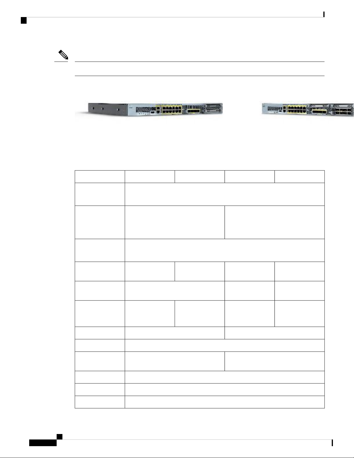
The Cisco Firepower 2100 series security appliance is a standalone modular security services platform. The
series includes the Firepower 2110, 2120, 2130, and 2140. See Product ID Numbers, on page 30 for a list of
the product IDs (PIDs) associated with the 2100 series.
The Firepower 2100 supports Cisco Firepower Threat Defense and Cisco ASA software. The Firepower 2100
is certified for the following security standards on ASA 9.8.x and FTD 6.2.x.
• Common Criteria (CC)
• Federal Information Processing Standards (FIPS)
• Department of Defense Information Network Approved Product List (DoDIN APL)
• US Government Compliance for IPv6 (USGv6)
Cisco Firepower 2100 Series Hardware Installation Guide
1
Page 6
Features
Note
The Firepower 2130 is Network Equipment Building Systems (NEBS)-certified.
Figure 1: Firepower 2110/2120 and Firepower 2130/2140
See the Cisco Interactive Library for a video that displays the features and components of the Firepower 2100.
The following table lists the features for the Firepower 2100 series.
Table 1: Firepower 2100 Series Features
2140213021202110Feature
Overview
Form factor
Rack mount
Airflow
Intel x86 processor
Cavium Network
Processor Unit
(NPU)
1 RU
Fits standard 19-in. (48.3-cm) square-hole rack.
Yes
Two 2-post mount brackets
(Optional) 4-post EIA-310-D rack
Yes
4-post EIA-310-D rack
(Optional) Two 2--post mount brackets
Front to rear
Cold aisle to hot aisle
Single 4-core at 1.8
G
16 GB DDR4 DRAMIntel x86 memory
Single 6-core at 1.9
G
Single 8-core at 2.0
G
32 GB DDR4
DRAM
Single 6-core at 1.2
G
Single 8-core at 1.2
G
Single 12-core at 1.2
G
16G8 GCavium NPU RAM
8 G (nominal)Flash
Single 16-core at 1.3
G
64 GB DDR4
DRAM
Single 16-core at 1.8
G
16Maximum number
24
of interfaces
1 Gigabit Ethernet (10 M/100 M/1 G Base-T)Management port
RJ-45 serial portConsole port
USB 2.0 Type A (500 mA)USB port
Cisco Firepower 2100 Series Hardware Installation Guide
2
Page 7

Overview
Features
2140213021202110Feature
12 fixed RJ-45 1 G/100 M/10 M ports (named Ethernet 1/1 through 1/12 )Network ports
Pullout asset card
Grounding lug
Locator beacon
Power switch
slots
Four fixed 1-G SFP portsSFP ports
Yes
Displays serial number
Yes
On rear panel
Yes
On front panel
Yes
On rear panel
NoNetwork module
—Network modules
Four fixed 1-G/10-G SFP+ ports
One
Not hot-swappable
8-port 1-Gigabit Ethernet SFP+
8-port 10-Gigabit Ethernet SFP+
6-port 1-Gigabit Ethernet SX fiber
fail-to-wire
6-port 10-Gigabit Ethernet SR fiber
fail-to-wire
6-port 10-Gigabit Ethernet LR fiber
fail-to-wire
One fixed AC power supply moduleAC power supply
Two power supply
slots
Ships with one
400-W AC power
supply modules
Hot-swappable
Two power supply
slots
Ships with two
400-W AC power
supply modules
Hot-swappable
Yes (optional)NoDC power supply
YesNoRedundant power
One hot-swappable fan tray with four fansFour fixed fansFan
Cisco Firepower 2100 Series Hardware Installation Guide
3
Page 8
Deployment Options
Overview
2140213021202110Feature
Storage
MSP
Deployment Options
Here are some examples of how you can deploy the Firepower 2100:
• As a firewall:
• At the enterprise Internet edge deployed in a high availability configuration
• At branch offices in either a high availability pair or standalone
• As a device that provides additional application control, URL filtering, or IPS/threat-centric capabilities:
• Behind an enterprise internet edge firewall in an inline in a transparent bump-in-the-wire configuration
or as a standalone (requires hardware fail open network module support)
Two SSD slots (100 GB )
Ships with one 100-GB SSD installed in
slot 1.
Slot 2 is reserved for the Malware Storage
Pack (MSP).
Yes
Installed in SSD slot 2.
Two SSD slots (200 GB )
Ships with one 200-GB SSD installed in
slot 1.
Slot 2 is reserved for the MSP.
• Deployed passively off a SPAN port on a switch or a tap on a network, or standalone
• As a VPN device:
• For remote access VPN
• For site-to-site VPN
Package Contents
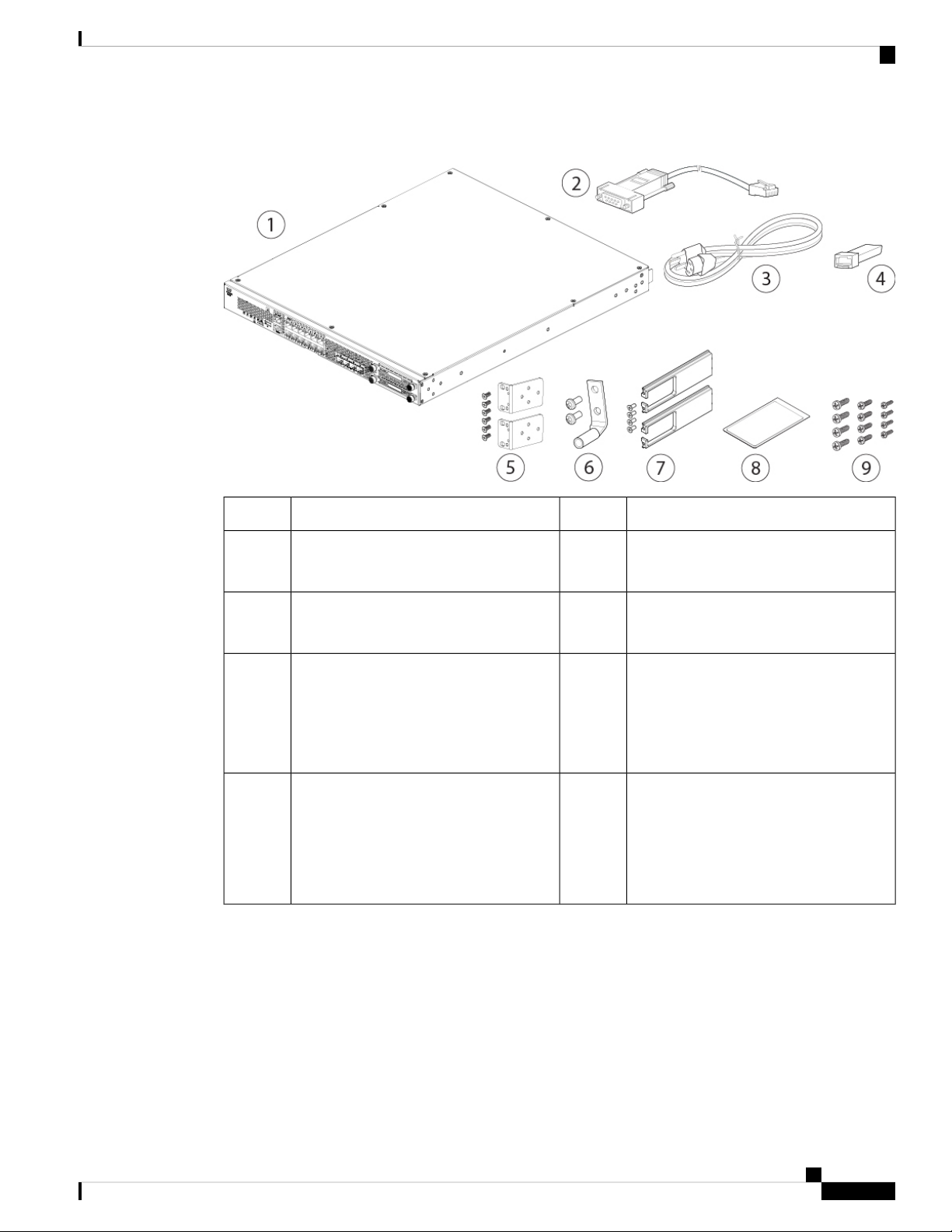
The following figure shows the package contents for the Firepower 2110 and 2120. The contents are subject
to change and your exact contents will contain additional or fewer items depending on whether you order the
optional parts. See Product ID Numbers, on page 30 for a list of the PIDs associated with the 2110 and 2120
package contents.
Cisco Firepower 2100 Series Hardware Installation Guide
4
Page 9
Overview
Package Contents
Figure 2: Firepower 2110 and 2120 Package Contents
Blue console cable PC terminal adapter2Firepower 2110 or 2120 chassis1
41 power cord (country-specific)3
SFP transceiver
(Optional; in package if ordered)
5
62 rack-mount brackets and six 8-32,
0.281-in. screws
7
8Cable management bracket kit
2 cable management brackets and four 8-32
x 0.375-in. screws
(Optional; in package if ordered)
9
Rack-mount screws:
1 ground lug kit
#6 AWG lug, two 10-32 x .38-in. screws
2 user documents:
• Useful Links Cisco Firepower 2100
Series document
• Start Here document
• Four 12-24, 0.75 in.
• Four 10-32, 0.75 in.
• Four M6, 19 mm
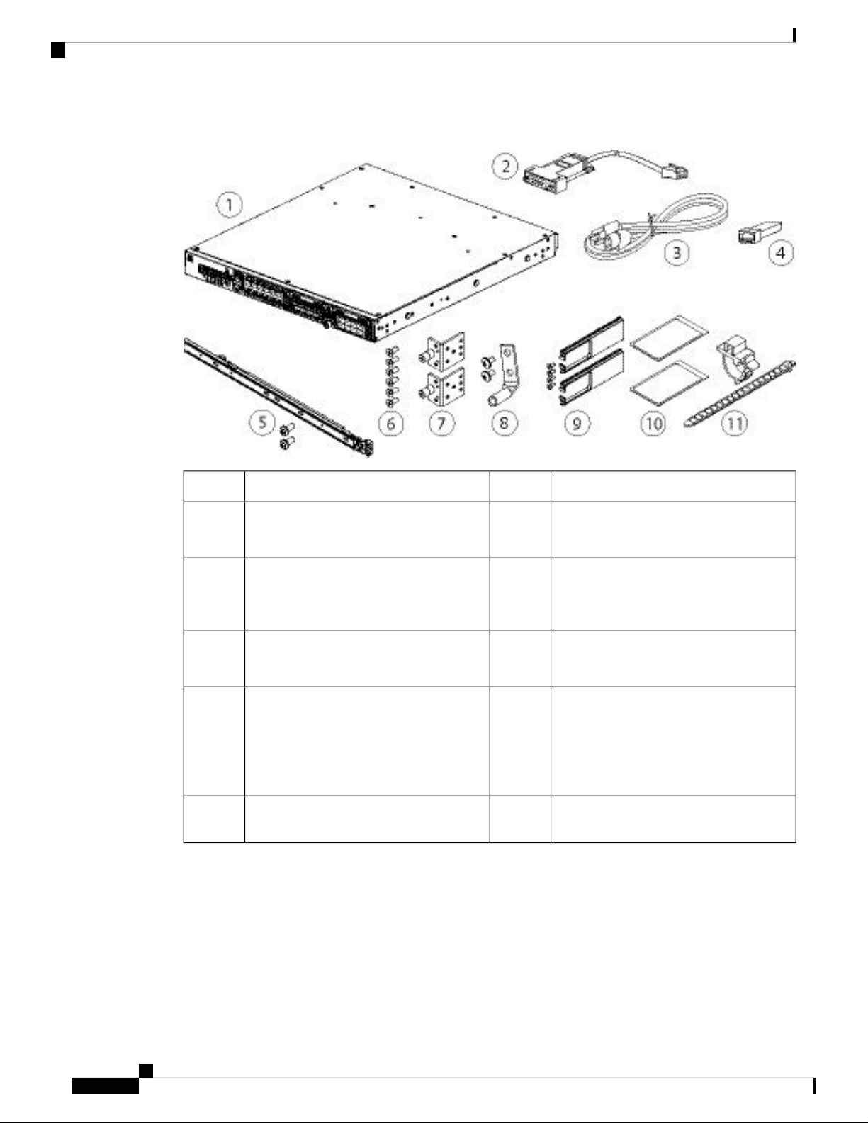
The following figure shows the package contents for the Firepower 2130 and 2140. The contents are subject
to change and your exact contents will contain additional or fewer items depending on whether you order the
optional parts. See Product ID Numbers, on page 30 for a list of the product IDs (PIDs) associated with the
2130 and 2140 package contents.
Cisco Firepower 2100 Series Hardware Installation Guide
5
Page 10
Serial Number Location
Overview
Figure 3: Firepower 2130 and 2140 Package Contents
5
9
11
Left and right slide rails and two M3x6
mm wafer head screws
2 cable management brackets and four 8-32
x 0.375-in. screws
(Optional; in package if ordered)
2 power supply module tie wraps and
clamps
Blue console cable PC terminal adapter2Firepower 2130 or 2140 chassis1
41 or 2 power cords (country-specific)3
6Slide rail kit
82 slide rail locking brackets7
10Cable management bracket kit
SFP transceiver
(Optional; in package if ordered)
Six 8-32 x .25-in. slide rail locking bracket
screws
1 ground lug kit
#6 AWG lug, two 10-32 x .38-in. screws
2 user documents:
• Useful Links Cisco Firepower 2100
Series document
• Start Here document
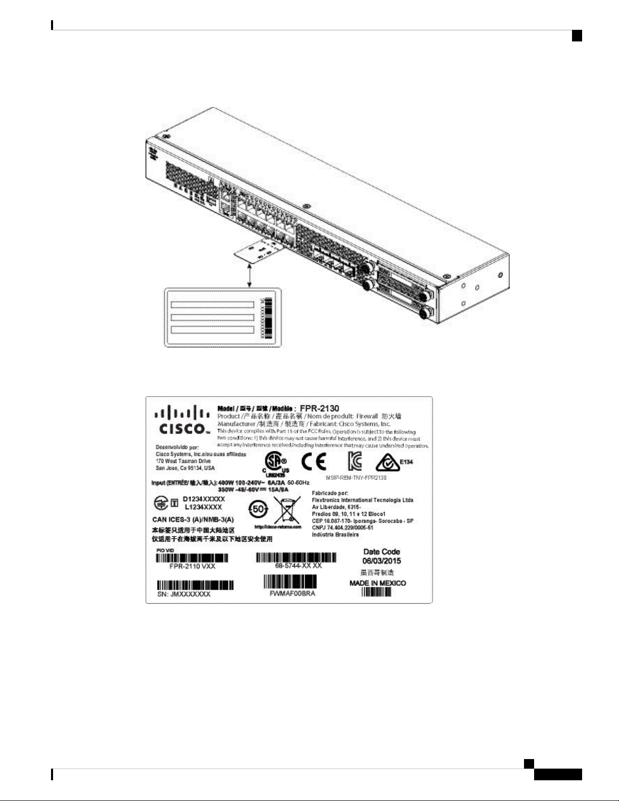
Serial Number Location
The serial number for the Firepower 2100 series chassis is located on the pullout asset card on the front panel.
Cisco Firepower 2100 Series Hardware Installation Guide
6
Page 11
Overview
Front Panel
Figure 4: Serial Number on the Chassis
Front Panel
You can also view additional model information on the compliance label located on the bottom of the chassis.
Figure 5: Compliance Label on the Chassis
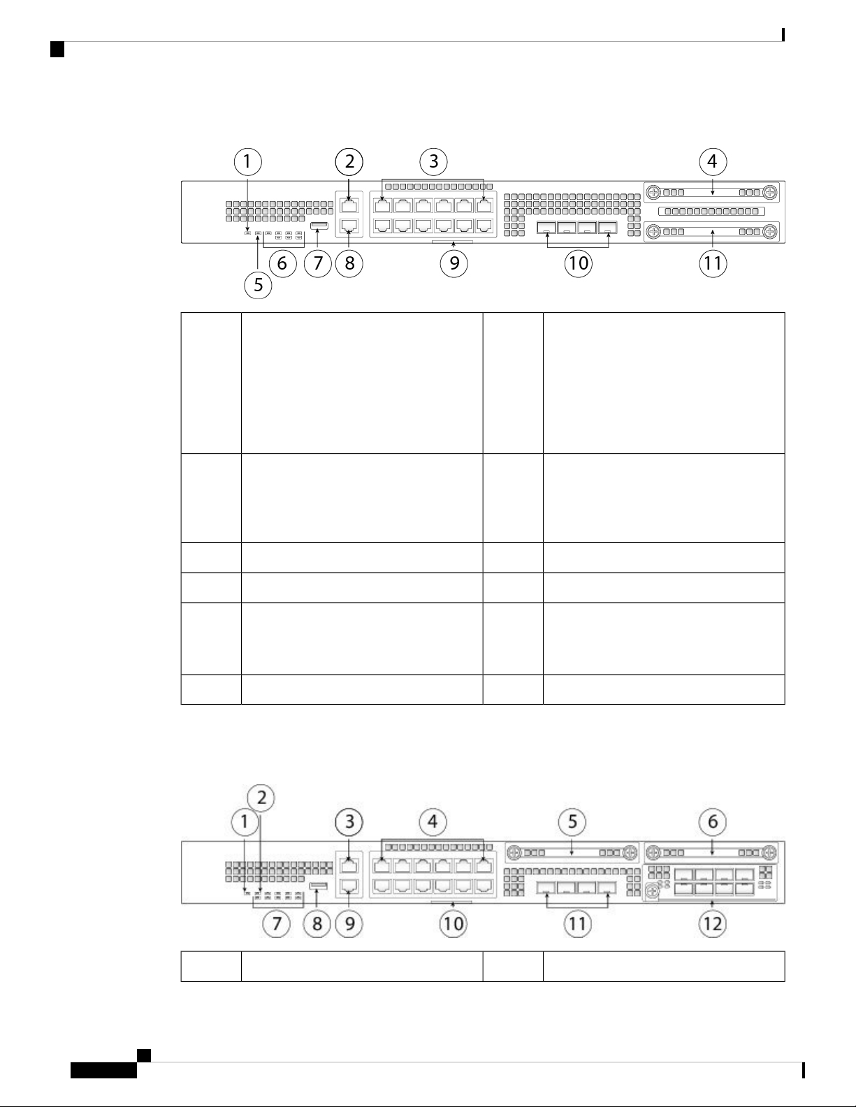
The following figure shows the front panel of the Firepower 2110 and 2120. See Front Panel LEDs, on page
10 for a description of the LEDs.
Cisco Firepower 2100 Series Hardware Installation Guide
7
Page 12
Front Panel
Overview
Figure 6: Firepower 2110 and 2120 Front Panel
2Power LED1
Gigabit Ethernet management port:
• Firepower Threat
Defense—Management 0 (also
referred to as Management 1/1 and
Diagnostic 1/1)
• ASA—Management 1/1
3
SSD 1 (slot 1)412 RJ-45 1 G/100 M/10 M auto
duplex/auto MDI-X Base-T ports
Ethernet 1/1 through 1/12 labeled top to
bottom, left to right
System LEDs6Locator beacon5
RJ-45 console port8Type A USB 2.0 port7
9
10Pullout asset card with chassis serial
number
4 fixed SFP (1 G) ports
Fiber ports 1/13 through 1/16 labeled left
to right
SSD (slot 2)11
The following figure shows the front panel of the Firepower 2130 and 2140. See Front Panel LEDs, on page
10 for a description of the LEDs.
Figure 7: Firepower 2130 and 2140 Front Panel
Locator beacon2Power LED1
Cisco Firepower 2100 Series Hardware Installation Guide
8
Page 13

Overview
Front Panel
3
4Gigabit Ethernet management port:
• Firepower Threat
Defense—Management 0 (also
referred to as Management 1/1 and
12 RJ-45 1 G/100 M/10 M auto
duplex/auto MDI-X Base-T ports
Ethernet 1/1 through 1/12 labeled top to
bottom, left to right
Diagnostic 1/1)
• ASA—Management 1/1
SSD 26SSD 15
Type A USB 2.0 port8System LEDs7
10RJ-45 console port9
Pullout asset card with chassis serial
number
11
Network module (network module slot 1)124 fixed SFP+ (1 G/10 G) ports
Fiber ports 1/13 through 1/16 labeled left
to right
Management Port
The Firepower 2100 chassis has an RJ-45 copper management port.
RJ-45 Console Port
The Firepower 2100 chassis has a standard RJ-45 console port. You can use the CLI to configure your
2100 through the RJ-45 serial console port by using a terminal server or a terminal emulation program
on a computer.
The RJ-45 (8P8C) port supports RS-232 signaling to an internal UART controller. The console port does
not have any hardware flow control, and does not support a remote dial-in modem. The baud rate is 9600.
You can use the standard cable found in your accessory kit to convert the RJ-45 to DB-9 if necessary.
Type A USB Port
You can use the external Type A USB port to attach a data-storage device. The external USB drive
identifier is disk1:. The Type A USB port supports the following:
• Hot swapping
• USB drive formatted with FAT32
• Boot kickstart image from ROMMON for discovery recovery purposes
• Copy files to and from workspace:/ and volatile:/ within local-mgmt. The most relevant files are:
• Core files
• Ethanalyzer packet captures
• Tech-support files
• Security module log files
• Platform bundle image upload using download image usbA:
The Type A USB port does not support Cisco Secure Package (CSP) image upload support.
Cisco Firepower 2100 Series Hardware Installation Guide
9
Page 14
Front Panel LEDs
Network Ports
The Firepower 2100 chassis has 12 fixed RJ-45 1 G/100 M/10 M) ports. They are numbered from top
to bottom, left to right starting with 1 and are named Ethernet 1/1 through Ethernet 1/12.
The 2110 and 2120 also have 4 fixed SFP (1 G) ports, and the 2130 and 2140 have 4 fixed SFP+ (1 G/10
G) ports. They are fiber ports numbered left to right (1/13 through 1/16).
Each port has LEDs that represent Link/Activity status.
Front Panel LEDs
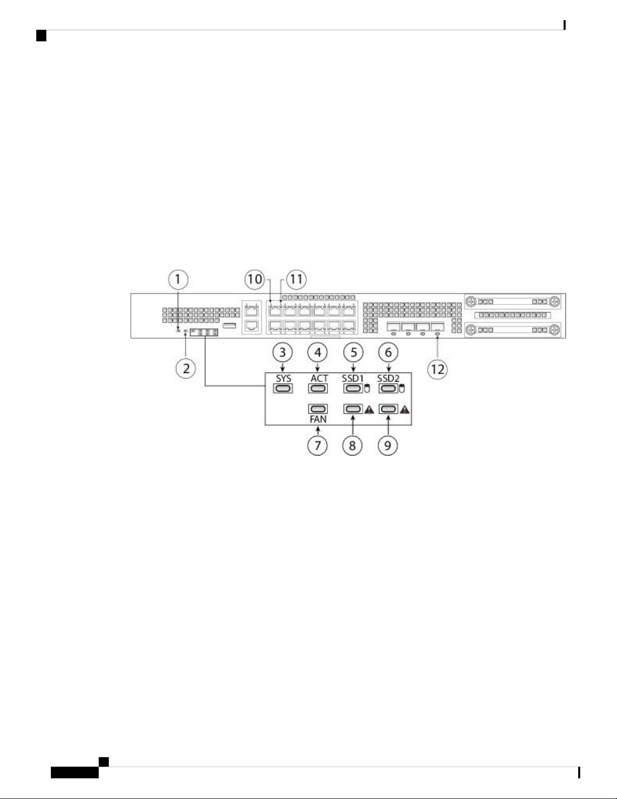
The following figure shows the Firepower 2110 and 2120 front panel LEDs.
Figure 8: Firepower 2110 and 2120 Front Panel LEDs
Overview
Cisco Firepower 2100 Series Hardware Installation Guide
10
Page 15

Overview
Front Panel LEDs
1
2PWR
• Off—Input power is not detected.
Standby power is off.
Locator Beacon
• Off—Locate is off.
• Blue—Locate is on.
• Green, flashing—The system has
detected a power switch toggle event,
and initiated the shutdown sequence.
If the power switch is in the OFF
position, the system powers off after
Note
The Locator beacon helps you
locate a unit that needs physical
service attention. This feature
is activated in the software.
shutdown is completed. Do not
remove the AC or DC power source
while this LED is blinking so that the
system has time to perform a graceful
shutdown.
• Amber—The system is powering up
(before the BIOS boots). This takes
one to five seconds at most.
• Green—The system is fully powered
up.
3
4SYS (Health)
• Off—The system has not booted up
yet.
ACT (Role of a high-availability pair)
• Off—The unit is not configured or
enabled in a high-availability pair.
• Green, flashing—The system is
booting up or in bootloader stage.
• Green—The unit is in active mode.
• Amber—The unit is in standby mode.
• Green—The system has fully booted.
• Amber—The system boot up has
failed.
• Amber, flashing—Alarm condition,
system needs service or attention and
may not boot properly.
5
6SSD1 ACT
• Off—SSD is not present.
• Green—SSD is present; no activity.
• Green, flashing—SSD is active.
SSD2 ACT
• Off—SSD is not present.
• Green—SSD is present; no activity.
• Green, flashing—SSD is active.
Cisco Firepower 2100 Series Hardware Installation Guide
11
Page 16

Front Panel LEDs
Overview
7
8FAN
• Off—The environmental subsystem
is not active yet.
SSD1 Alert Status
• Off—SSD has normal activity.
• Amber—SSD failure.
• Green—The fans are running
normally. It may take up to one
minute for the LED status to turn
green after power is on.
• Amber—One fan has failed. The
system can continue to operate
normally, but fan service is required.
• Amber, flashing—Two or more fans
have failed, or the fan tray has been
removed from the system. Immediate
attention is required.
9
10SSD2 Alert Status
• Off—SSD has normal activity.
• Amber—SSD failure.
Ethernet Link
• Green—The link partner is detected;
no activity.
• Green, flashing—Network activity is
detected.
11
12Ethernet Speed
• Green, flashing—The number of
flashes determines link speed; 1
flash=10 Mbit, 2=100 Mbit, 3=1 Gbit.
Fiber Port
• Green—Port is enabled, the link
partner is detected.
• Amber—Port is enabled, but the link
partner is not detected.
• Green, flashing—Port is enabled;
network activity is detected.
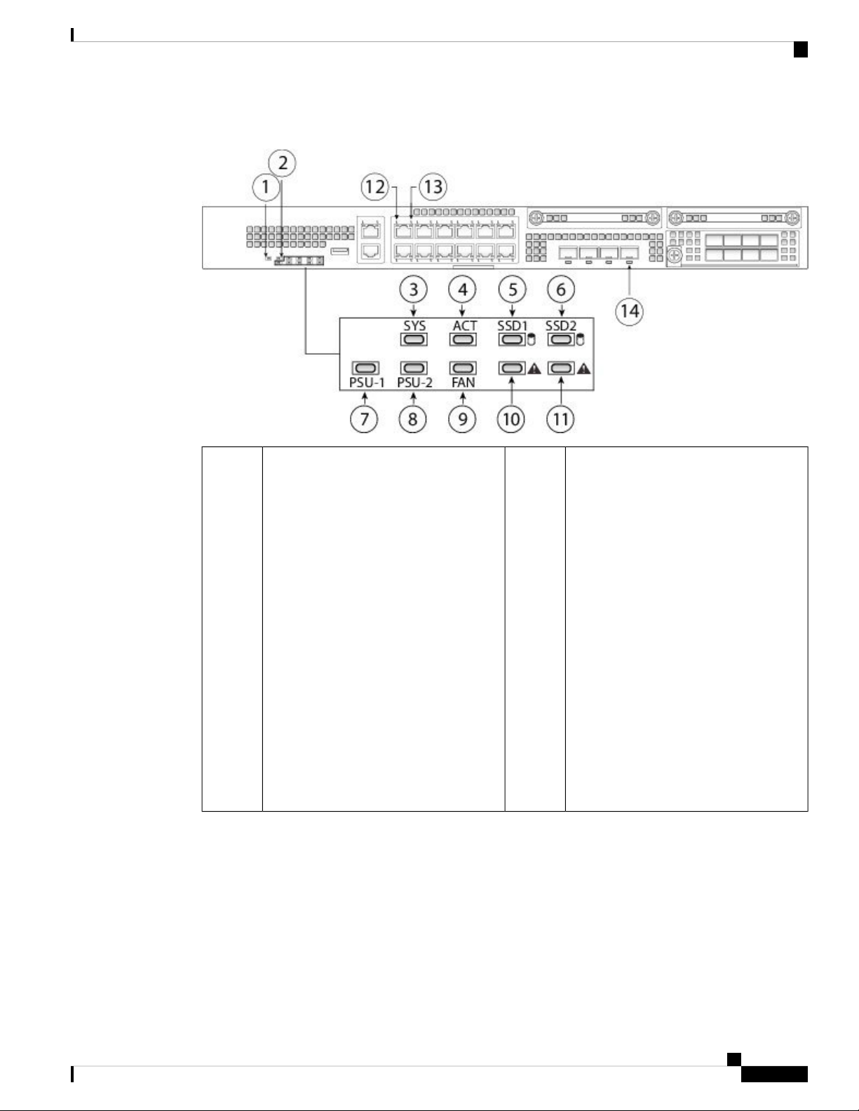
The following figure shows the Firepower 2130 and 2140 front panel LEDs.
Cisco Firepower 2100 Series Hardware Installation Guide
12
Page 17
Overview
Front Panel LEDs
Figure 9: Firepower 2130 and 2140 Front Panel LEDs
1
2Power
• Off—Input power is not detected.
Standby power is off.
Locator LED
• Off—Locate is off.
• Blue—Locate is on.
• Green, flashing—The system has
detected a power switch toggle event,
and initiated the shutdown sequence.
If the power switch is in the OFF
position, the system powers off after
Note
The Locator beacon helps you
locate a unit that needs physical
service attention. This feature
is activated in the software.
shutdown is completed. Do not
remove the AC or DC power source
while this LED is blinking so that the
system has time to perform a graceful
shutdown.
• Amber—The system is powering up
(before the BIOS boots). This takes
one to five seconds at most.
• Green—The system is fully powered
up.
Cisco Firepower 2100 Series Hardware Installation Guide
13
Page 18

Front Panel LEDs
Overview
3
4SYS (Health)
• Off—The system has not booted up
yet.
• Green, flashing—The system is
booting up or in bootloader stage.
ACT (Role of a high-availability pair)
• Off—The unit is not configured or
enabled in a high-availability pair.
• Green—The unit is in active mode.
• Amber—The unit is in standby mode.
• Green—The system has fully booted.
• Amber—The system boot up has
failed.
• Amber, flashing—Alarm condition,
system needs service or attention and
may not boot properly.
5
6SSD1 ACT
• Off—The SSD is not present.
• Green—The SSD is present; no
activity.
• Green, flashing—The SSD is active.
7
8PSU-1
SSD2 ACT
• Off—The SSD is not present.
• Green—The SSD is present; no
activity.
• Green, flashing—The SSD is active.
PSU-2
• Off—The power supply module is not
present or not detected.
• Green—The power supply module is
present and working properly.
• Amber—The power supply module
is present but a fault or problem has
been detected.
9
10FAN
• Off—The environmental subsystem
is not active yet.
• Off—The power supply module is not
present or not detected.
• Green—The power supply module is
present and working properly.
• Amber—The power supply module
is present but a fault or problem has
been detected.
SSD1 Alert Status
• Off—SSD has normal activity.
• Amber—SSD failure.
• Green—The fans are running
normally. It may take up to one
minute for the LED status to turn
green after power is on.
• Amber—One fan has failed. The
system can continue to operate
normally, but fan service is required.
• Amber, flashing—Two or more fans
have failed, or the fan tray has been
removed from the system. Immediate
attention is required.
Cisco Firepower 2100 Series Hardware Installation Guide
14
Page 19
Overview
Rear Panel
Rear Panel
11
• Off—SSD has normal activity.
• Amber—SSD failure.
13
• Green, flashing—The number of
flashes determines link speed; 1
flash=10 Mbit, 2=100 Mbit, 3=1 Gbit.
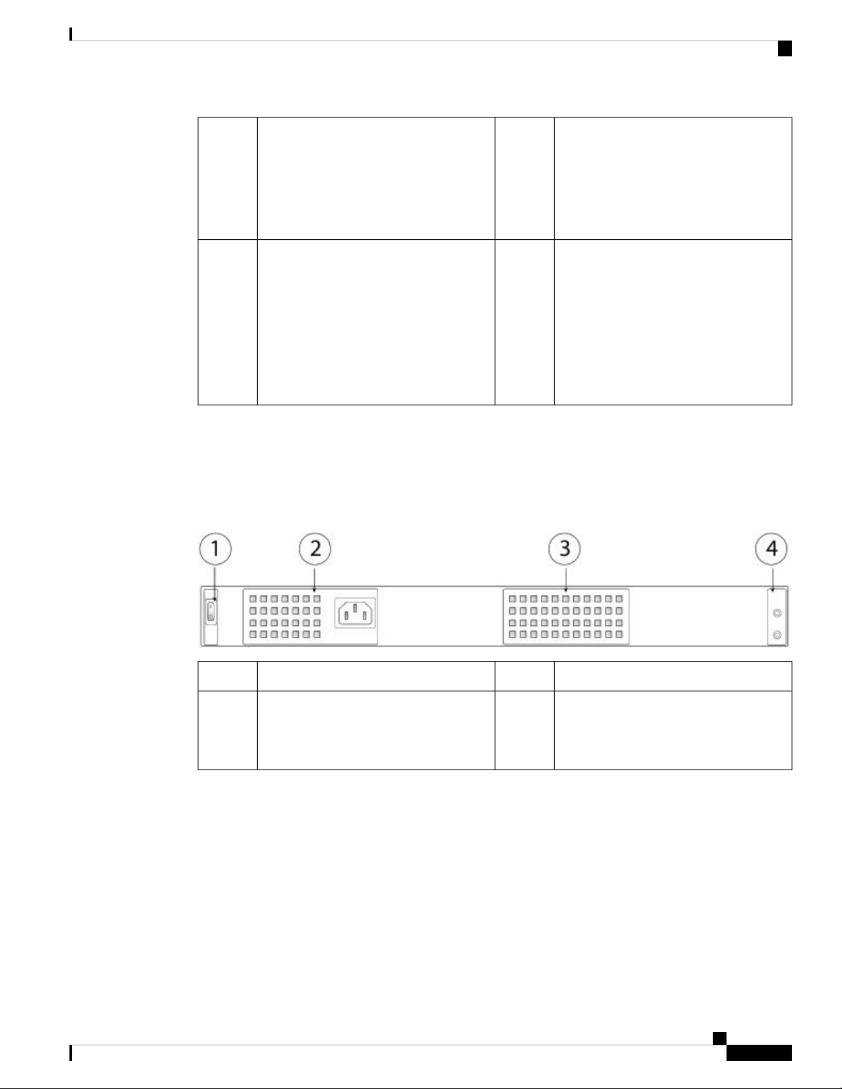
The following figure shows the rear panel of the Firepower 2110 and 2120.
Figure 10: Firepower 2110 and 2120 Rear Panel
12SSD2 Alert Status
14Ethernet Speed
Ethernet Link
• Green—The link partner is detected;
no activity.
• Green, flashing—Network activity is
detected.
Fiber Port
• Green—Port is enabled, the link
partner is detected.
• Amber—Port is enabled, but the link
partner is not detected.
• Green, flashing—Port is enabled;
network activity is detected.
Fixed power supply module2Power on/off switch1
4Fixed fans3
The following figure shows the rear panel of the Firepower 2130 and 2140.
Cisco Firepower 2100 Series Hardware Installation Guide
2-post grounding lug
Note
The 2-post grounding lug is
included in the accessory kit.
15
Page 20
Rear Panel
Overview
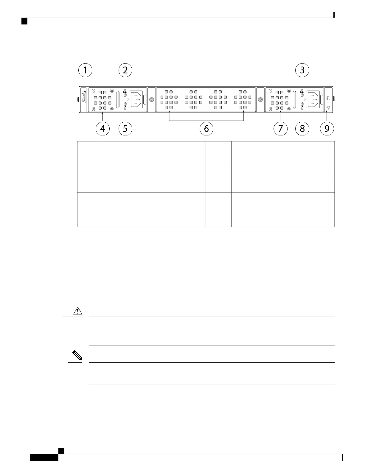
Figure 11: Firepower 2130 and 2140 Rear Panel
Power supply module 1 FAIL LED2Power on/off switch1
Power supply module 14Power supply module 2 FAIL LED3
Fan tray6Power supply module 1 OK LED5
Power supply module 2 OK LED8Power supply module 27
9
Power Switch
Caution
Note
2-post grounding lug
Note
The 2-post grounding lug is
included in the accessory kit.
The power switch is located to the left of power supply module 1 on the rear of the chassis. It is a toggle
switch that controls power to the system. If the power switch is in standby position, only the 3.3-V
standby power is enabled from the power supply module and the 12-V main power is OFF. When the
switch is in the ON position, the 12-V main power is turned on and the system boots.
Before you move the power switch to the OFF position, use the shutdown commands so that the system
can perform a graceful shutdown. This may take several minutes to complete. After the graceful shutdown
is completed, the front panel power LED is unlit and the console displays Power Down. See the FXOS
Configuration Guide for more information on using these commands.
If you move the power switch to the OFF position before the shutdown command sequence has completed
or if you remove the system power cords before the graceful shutdown is complete, disk corruption can
occur.
After removing power from the chassis by unplugging the power cord, wait at least 10 seconds before
turning power back ON.
For More Information
• See Remove and Replace the Power Supply Module, on page 70 for the procedure for removing and
replacing the power supply module in the Firepower 2130 and 2140.
Cisco Firepower 2100 Series Hardware Installation Guide
16
Page 21

Overview
• See Remove and Replace the Fan Tray, on page 78 for the procedure for removing and replacing the
fan tray in the Firepower 2130 and 2140.
• See Ground the Chassis, on page 54 for the procedure for using the grounding lug to ground the chassis.
• See Power Supply Modules, on page 23 for a description of the power supply module LEDs.
• See Front Panel LEDs, on page 10 for a description of the fan LEDs.
Network Modules
The Firepower 2130 and 2140 contain one network module slot that provides optical or electrical network
interfaces. Network modules are optional, removable I/O modules that provide either additional ports or
different interface types. The Firepower network module plugs into the chassis on the front panel.
For More Information
• See 10-G Network Module , on page 17 for a description of the 10-G network module.
• See Supported SFP/SFP+ Transceivers, on page 26 for a list of supported SFPS.
Network Modules
• See Remove and Replace the Network Module, on page 67 for the procedure for removing and replacing
network modules.
10-G Network Module
The following figure shows the front panel of the 10-G network module (FPR2K-NM-8X10G). The
FPR2K-NM-8X10G is a single-wide module that supports hot swapping. The eight ports are numbered from
top to bottom, left to right.
Note
The FPR2K-NM-8X10G is NEBS-compliant.
Note
You can fit four copper SFPs in either the top row of ports or the bottom row of ports. Both rows cannot be
populated at the same time, because of the port row spacing.
Cisco Firepower 2100 Series Hardware Installation Guide
17
Page 22

1-G Network Module
Overview
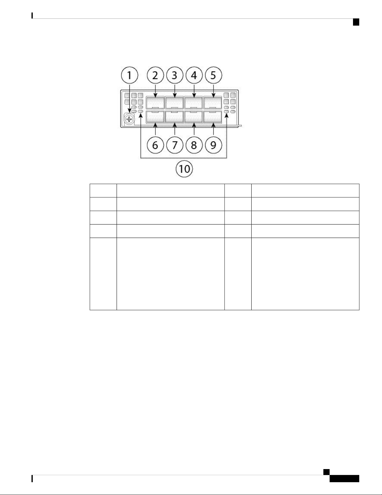
Figure 12: FPR2K-NM-8X10G
3
5
7
9
1-G Network Module
The following figure shows the front panel of the 1-G network module (FPR2K-NM-8X1G). The
FPR2K-NM-8X1G is a single-wide module that supports hot swapping. The eight ports are numbered from
top to bottom, left to right.
Ethernet X/3
Ethernet X/7
Ethernet X/4
Ethernet X/8
2Captive screw/handle1
4
6
8
10
Ethernet X/1
Ethernet X/5
Ethernet X/2
Ethernet X/6
Network activity LEDs
• Off—No connection or port is not in
use.
• Amber—No link or network failure.
• Green—Link up.
• Green, flashing—Network activity.
Note
You can fit four copper SFPs in either the top row of ports or the bottom row of ports. Both rows cannot be
populated at the same time, because of the port row spacing. For a list of copper SFPS, see Supported SFP/SFP+
and QSFP Transceivers.
Cisco Firepower 2100 Series Hardware Installation Guide
18
Page 23
Overview
Hardware Bypass Network Modules
Figure 13: FPR2K-NM-8X1G
3
5
7
9
Ethernet X/3
Ethernet X/7
Ethernet X/4
Ethernet X/8
Hardware Bypass Network Modules
Fail-to-wire (also known as hardware bypass) is a physical layer (Layer 1) bypass that allows paired interfaces
to go into bypass mode so that the hardware forwards packets between these port pairs without software
intervention. Fail-to-wire provides network connectivity when there are software or hardware failures. Hardware
bypass is useful on ports where the Firepower security appliance is only monitoring or logging traffic. The
hardware bypass network modules have an optical switch that is capable of connecting the two ports when
needed.
2Captive screw/handle1
4
6
8
10
Ethernet X/1
Ethernet X/5
Ethernet X/2
Ethernet X/6
Network activity LEDs
• Unlit—No connection or port is not
in use.
• Amber—No link or network failure.
• Green—Link up.
• Green, flashing—Network activity.
The fail-to-wire network modules have built-in SFPs.
Hardware bypass is supported only on a fixed set of ports. You can pair Port 1 with Port 2, Port 3 with Port
4, but you cannot pair Port 1 with Port 4 for example.
Cisco Firepower 2100 Series Hardware Installation Guide
19
Page 24

1-G SX/10-G SR/10-G LR Network Module with Hardware Bypass
Note
Hardware bypass is only supported in inline mode. Also, hardware bypass support depends on your software
application.
Note
When the appliance switches from normal operation to hardware bypass or from hardware bypass back to
normal operation, traffic may be interrupted for several seconds. A number of factors can affect the length of
the interruption; for example, behavior of the optical link partner such as how it handles link faults and
debounce timing; spanning tree protocol convergence; dynamic routing protocol convergence; and so on.
During this time, you may experience dropped connections.
There are three configuration options for hardware bypass network modules:
• Passive interfaces—Connection to a single port.
For each network segment you want to monitor passively, connect the cables to one interface. This is
how the non-fail-to-wire network modules operate.
Overview
• Inline interfaces—Connection to any two like ports (10 G to 10 G for example) on one network module,
across network modules, or fixed ports.
For each network segment you want to monitor inline, connect the cables to pairs of interfaces.
• Inline with fail-to-wire interfaces—Connection of a fail-to-wire paired set.
For each network segment that you want to configure inline with fail-open, connect the cables to the
paired interface set.
For the 40-G network module, you connect the two ports to form a paired set. For the 1/10-G network
modules, you connect the top port to the bottom port to form a fail-to-wire paired set. This allows traffic
to flow even if the security appliance fails or loses power.
Note
If you have a inline interface set with a mix of fail-to-wire and non-fail-to-wire interfaces, you cannot enable
hardware bypass on this inline interface set. You can only enable hardware bypass on an inline interface set
if all the pairs in the inline set are valid fail-to-wire pairs.
For More Information
• See 1-G SX/10-G SR/10-G LR Network Module with Hardware Bypass, on page 20 for a description
of the 1-G SX, 10-G SR, and LR network modules.
• See Remove and Replace the Network Module, on page 67 for the procedure for removing and
replacing single-wide network modules.
1-G SX/10-G SR/10-G LR Network Module with Hardware Bypass
The following figure shows the front panel of the 1-G SX, 10-G SR and 10-G LR fail-to-wire network modules
FPRK2-NM-6X1SX-F, FPRK2-NM-6X10SR-F, FPR2K-NM-6X10LR-F). This is a single-wide module that
Cisco Firepower 2100 Series Hardware Installation Guide
20
Page 25
Overview
1-G SX/10-G SR/10-G LR Network Module with Hardware Bypass
does not support hot swapping. The six ports are numbered from top to bottom, left to right. Pair ports 1 and
2, 3 and 4, and 5 and 6 to form hardware bypass paired sets.
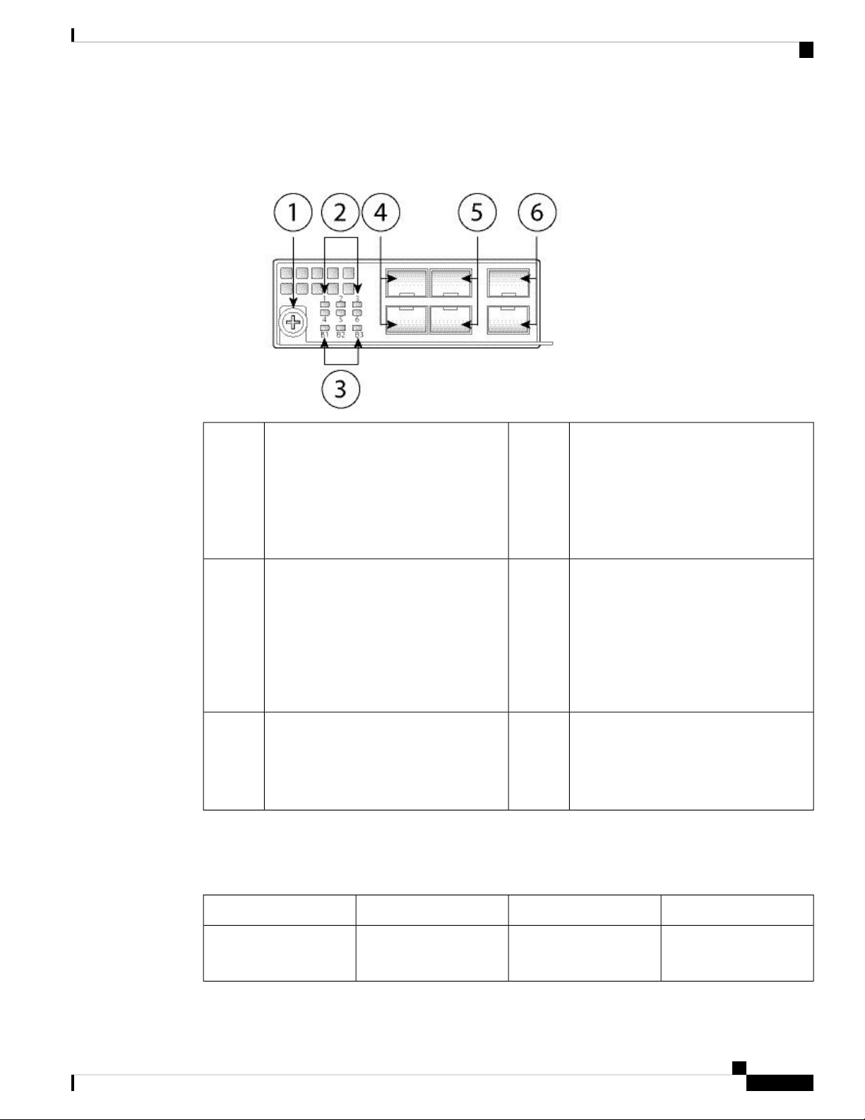
Figure 14: FPR2K-NM-6X1SX-F, FPR2K-NM-6X10SR-F, FPR2K-NM-6X10LR-F
2Captive screw/handle1
6 network activity LEDs
• Amber—No connection, or port is not
in use, or no link or network failure.
• Green—Link up, no network activity.
• Green, flashing—Network activity.
3
• Green—In standby mode.
• Amber, flashing—Port is in hardware
bypass mode, failure event.
4Bypass LEDs B1 through B3:
Ethernet X/1 (top port)
Ethernet X/2 (bottom port)
Ports 1 and 2 are paired together to form a
hardware bypass pair.
• Amber—Port is in hardware bypass
mode, forced.
5
Ethernet X/3 (top port)
Ethernet X/4 (bottom port)
Ports 3 and 4 are paired together to form
a hardware bypass pair.
6
Ethernet X/5 (top port)
Ethernet X/6 (bottom port)
Ports 5 and 6 are paired together to form a
hardware bypass pair.
The 1-G SX /10-G SR/10-G LR network modules have the following insertion loss measurements. Insertion
loss measurements help you to troubleshoot the network by verifying cable installation and performance.
Table 2: 1-G SX Network Module (FPR2K-NM-6X1SX-F)
Insertion loss
Normal
Hardware bypass
MaximumTypicalOperating Mode
0.9 dB
1.2 dB
Cisco Firepower 2100 Series Hardware Installation Guide
1.4 dB
1.7 dB
21
Page 26
1-G SX/10-G SR/10-G LR Network Module with Hardware Bypass
Overview
Core diameter (microns)
Cable and operating
distance
62.5
62.5
50
50
50
Table 3: 10-G SR Network Module (FPR2K-NM-6X10SR-F)
Insertion loss
Normal
Hardware bypass
Core diameter (microns)
Modal bandwidth
(MHz/km)
160 (FDDI)
200 (OM1)
400
500 (OM2)
2000 (OM3)
0.9 dB
1.2 dB
Modal bandwidth
(MHz/km
Cable distance
Note
Half the
distance
specified by
the IEEE
standard.
110 m
137 m
250 m
275 m
500 m
MaximumTypicalOperating Mode
1.4 dB
1.7 dB
Cable distance
Note
Half the
distance
specified by
the IEEE
standard.
Cable and operating
distance
62.5
62.5
50
50
50
50
Table 4: 10-G LR Network Module (FPR2K-NM-6X10LR-F)
160 (FDDI)
200 (OM1)
400
500 (OM2)
2000 (OM3)
4700 (OM4)
13 m
16.5 m
33 m
41 m
150 m
200 m
MaximumTypicalOperating Mode
Insertion loss
Normal
Hardware bypass
Cisco Firepower 2100 Series Hardware Installation Guide
22
1.2 dB
1.5 dB
1.6 dB
1.9 dB
Page 27

Overview
Power Supply Modules
distance
Power Supply Modules
The Firepower 2110 and 2120 have one fixed AC power supply that is not field-replaceable. If the power
supply fails, you must send your Firepower 2110 or 2120 for RMA.
The Firepower 2130 and 2140 support two AC power supply modules so that dual power supply redundancy
protection is available. The Firepower 2130 ships with one AC power supply and the Firepower 2140 ships
with two AC power supplies. You can also install DC power supply modules instead of AC power on the
2130 and 2140. Facing the back of the chassis, the power supply modules are numbered left to right, for
example, PSU1 and PSU2.
The power supply module is hot-swappable.
Core diameter (microns)
Modal bandwidth
(MHz/km
Cable distance
Note
Half the
distance
specified by
the IEEE
standard.
5 kmSingle modeG.652Cable and operating
Note
Note
Attention
Note
See Product ID Numbers, on page 30 for a list of the PIDs associated with the 2100 series power supply
modules.
You cannot mix AC and DC power supply modules in the chassis.
After removing power from the chassis by unplugging the power cord, wait at least 10 seconds before turning
power back ON.
Make sure that one power supply module is always active.
The system power requirements are lower than the power supply module capabilities. See the following table.
AC Power Supply
The dual power supplies can supply up to 800-W power across the input voltage range. The load is shared
when both power supply modules are plugged in and running at the same time.
Cisco Firepower 2100 Series Hardware Installation Guide
23
Page 28

Power Supply Modules
Note
Overview
The system does not consume more than the capacity of one power supply module, so it will always operate
in full redundancy mode (2130 and 2140 only) when two power supply modules are installed.
Table 5: AC Power Supply Module Hardware Specifications
2140213021202110
100 to 240 V ACInput voltage
< 4 AMaximum input
< 6 A
current
400 W250 WMaximum output
power
50 to 60 HzFrequency
85% at 50% loadEfficiency
89% at 50% load
800W—Maximum
redundancy output
power
—Redundancy
1+1 redundancy with dual power supply
modules
DC Power Supply
The power supplies can supply up to 350 W power across the input voltage range. The load is shared when
both power supply modules are plugged in and running at the same time.
Table 6: DC Power Supply Module Hardware Specifications
21402130
-48 to -60 V DCInput voltage
Maximum input current
< 15 A at -48 V
Note
The power supply module is rated at 15 A but the system
power is limited to 6.1 A. See Hardware Specifications, on
page 29 for more system specifications.
350 WMaximum output power
1+1 redundancy with dual power supply modulesRedundancy
> 88% at 50% loadEfficiency
Cisco Firepower 2100 Series Hardware Installation Guide
24
Page 29

Overview
Fan Modules
Power Supply Module LEDs
The following figure shows the bicolor power supply LEDs on the power supply module. The figure shows
the AC power supply module. The DC power supply module has the same LEDs.
Figure 15: Power Supply Module LEDs
Green OK LED2Amber FAIL LED1
The following describes the power module supply LEDs.
Green LED (OK Status)
• Off—Input power not present.
• Green, flashing—Input power present, but system is not powered up (power switch is off).
• Green—The power supply module is enabled and running.
Amber LED (Fail Status)
• Off—No fault detected.
• Amber, flashing—Fault warning, power supply may still work but could fail due to high temperature,
failing fan, or over current.
• Amber—Fault detected; power supply not working properly. Includes over voltage, over current, over
temperature, and fan failure.
For More Information
• See Remove and Replace the Power Supply Module, on page 70 for the procedure for removing and
replacing the power supply module in the Firepower 2130 and 2140.
Fan Modules
The Firepower 2110 and 2120 have four fixed fans. If the fans fail, you must send your 2110 or 2120 for
RMA.
Cisco Firepower 2100 Series Hardware Installation Guide
25
Page 30

SSDs
SSDs
Overview
The Firepower 2130 and 2140 have a removable fan tray with 3 + 1 redundant fans that are hot-swappable.
The fan tray is installed in the rear of the chassis. Any one fan can fail indefinitely and the system continues
to function. When a fan fails, the remaining fans automatically spin up to full speed.
The fan LED is located on the front of the chassis. See Product ID Numbers, on page 30 for a list of the PIDs
associated with the 2100 series fans.
For More Information
• See Front Panel LEDs, on page 10 for the location and description of the fan LED.
• See Remove and Replace the Fan Tray, on page 78 for the procedure for removing and replacing the
fan tray.
The Firepower 2110 and 2120 have two SSD slots. These models ship with one 100-GB SSD installed in slot
1. The Firepower 2130 and 2140 have two SSD slots. These models ship with one 200-GB SSD installed in
slot 1. See Product ID Numbers, on page 30 for a list of the PIDs associated with the 2100 series SSDs.
Caution
Note
You can use the second SSD slot to upgrade to the MSP. The MSP must be installed in the second slot. The
second SSD slot remains empty unless you install the MSP in the second slot. The MSP stores threat detection
results for use in future analysis. It supports the Advanced Malware Protection (AMP) software feature. It is
used as both storage and as the Malware application repository. RAID is not supported.
You cannot swap SSDs between different Firepower platforms. For example, you cannot use a 4100 series
SSD in a 2100 series security appliance.
The 100-GB SSD is restricted to the 2110 and 2120 models. The 200-GB SSD is restricted to the 2130 and
2140 models. Do not mix them.
Although the hardware supports hot swapping for the SSDs, the software does not, so you must power down
the chassis before removing and replacing them.
For More Information
• See Front Panel LEDs, on page 10 for the location and description of the SSD LEDs on the front panel.
• See Remove and Replace the SSD, on page 68 for the procedure for removing and replacing the SSD.
Supported SFP/SFP+ Transceivers
Take note of the following warnings:
Cisco Firepower 2100 Series Hardware Installation Guide
26
Page 31

Overview
Supported SFP/SFP+ Transceivers
Warning
Warning
Warning
Warning
Statement 1053—Class 1M Laser Radiation
Class 1M laser radiation when open. Do not view directly with optical instruments.
Statement 1055—Class I and Class 1M Laser
Class I (CDRH) and Class 1M (IEC) laser products.
Statement 1056—Unterminated Fiber Cable
Invisible laser radiation may be emitted from the end of the unterminated fiber cable or connector. Do not
view directly with optical instruments. Viewing the laser output with certain optical instruments (for example,
eye loupes, magnifiers, and microscopes) within a distance of 100 mm may pose an eye hazard.
Statement 1057—Hazardous Radiation Exposure
Use of controls or adjustments or performance of procedures other than those specified may result in hazardous
radiation exposure.
The SFP/SFP+ transceiver is a bidirectional device with a transmitter and receiver in the same physical
package. It is a hot-swappable optical or electrical (copper) interface that plugs into the SFP/SFP+ ports on
the fixed ports and the network module ports, and provides Ethernet connectivity.
Figure 16: SFP
Bail clasp2Dust plug1
Transmit optical bore4Receive optical bore3
Cisco Firepower 2100 Series Hardware Installation Guide
27
Page 32

Supported SFP/SFP+ Transceivers
Overview
Warning
Note
Caution
Use appropriate ESD procedures when inserting the transceiver. Avoid touching the contacts at the rear, and
keep the contacts and ports free of dust and dirt. Keep unused transceivers in the ESD packing that they were
shipped in.
The 1-G transceivers are limited to 1-GB operation only (no auto-negotiation support). 100-M/10-M modes
are not supported.
Although non-Cisco SFPs are allowed, we do not recommend using them because they have not been tested
and validated by Cisco. Cisco TAC may refuse support for any interoperability problems that result from
using an untested third-party SFP transceiver.
The following table lists the supported transceivers.
Table 7: Supported SFPs
Ports SupportedPIDOptics Type
SFP 1G
1G-SX
GLC-SX-MMD
Ports 13 through 16
SFP+ 10G
GLC-LH-SMD1G-LH
Ports 1 though 8 of the 8X10G network
module (available only on the 2130 and 2140)
GLC-EX-SMD1G-EX
GLC-ZX-SMD1G-ZX
GLC-T1G 1000Base-T
Supported on the Firepower 2130 and 2140.
Supported on the Firepower 2130 and 2140.GLC-TE1G 1000Base-T
Cisco Firepower 2100 Series Hardware Installation Guide
28
Page 33

Overview
Hardware Specifications
10G-SR
H10GB-CU 1M, 1.5M, 2M,
2.5M, 3M, 5M
H10GB-ACU 7M, 10M
SFP-10G-SR
SFP-10G-LR10G-LR
SFP-10G-LRM10G-LRM
SFP-10G-ER10G-ER
SFP-10G-SR-S10G-SR-S
SFP-10G-LR-S10G-LR-S
SFP-10G-ZR-S10G-ZR-S
SFP-10G-ER-S10G-ER-S
SFP-H10GB-CU1M
SFP-H10GB-CU1-5M
SFP-H10GB-CU2M
SFP-H10GB-CU2-5
SFP-H10GB-CU3M
SFP-H10GB-CU5M
SFP-H10GB-ACU7M
Ports 13 through 16
Ports 1 though 8 of the 8X10G network
module (available only on the 2130 and 2140)
10G-AOC 1M, 2M, 3M, 5M,
7M, 10M
Hardware Specifications
The following table contains hardware specifications for the Firepower 2100 series security appliance.
1.73 x 16.90 x 19.76 in. (4.4 x 42.9 x 50.2 cm)Chassis dimensions
(H x W x D)
1.2 x 3.7 x 9.6 in. (4.39 x 9.4 x 24.38)Network module
dimensions
SFP-H10GB-ACU10M
SFP-10G-AOC1M
SFP-10G-AOC2M
SFP-10G-AOC3M
SFP-10G-AOC5M
SFP-10G-AOC7M
SFP-10G-AOC10M
2140213021202110Specification
16.1 lb (7.3 kg)Weight
Cisco Firepower 2100 Series Hardware Installation Guide
21 lb (9.52 kg)19.4 lb (8.79 kg)
29
Page 34

Product ID Numbers
Overview
2140213021202110Specification
System power
Temperature
NEBS
Humidity
Altitude
100/240V AC 1.9 A (at 100 VAC), 50 to
60 Hz
Note
The power supply module is
rated at 4 A, but the system
power is limited to 1.9 A.
100/240 V AC 2.9 A (at 100 VAC), 50 to
60 Hz
Note
The power supply module is
rated at 6.3 A, but the system
power is limited to 2.9 A.
Operating: 32 to 104°F (0 to 40°C)
Nonoperating: -40 to 149°F (-40 to 65°C) maximum altitude is 40,000 ft
Operating altitude: 0 to 13,000 ft (3962 m)
Operating temperature:
• Long Term: 0 to 45°C up to 6000 ft (1829 m)
• Long Term: 0 to 35°C 6000-13000 ft (1829-3964 m)
• Short Term: -5 to 55°C up to 6000 ft (1829 m)
Note
Firepower 2100 series NEBS compliance applies only to the 2130.
Operating: 10 to 85 % noncondensing
Nonoperating: 5 to 95 % noncondensing
Operating: 10,000 ft maximum
Sound pressure
Sound power
Product ID Numbers
The following table lists all of the PIDs associated with the Firepower 2100 series. See the show inventory
and show inventory expand commands in the Cisco FXOS Troubleshooting Guide for the Firepower 2100
Series to display a list of the PIDs for your Firepower 2100.
Table 8: Firepower 2100 Series PIDs
Nonoperating: 40,000 ft maximum
47.3 dBA (typical)
73.4 dBA (maximum)
60.2 (typical)
85.1 (maximum)
DescriptionPID
Cisco Firepower 2110 NGFW appliance 1 RUFPR2110-NGFW-K9
Cisco Firepower 2120 NGFW appliance 1 RUFPR2120-NGFW-K9
55.7 dBA (typical)
76.7 dBA (maximum)
66 (typical)
84.5 (maximum)
Cisco Firepower 2100 Series Hardware Installation Guide
30
Page 35

Overview
Product ID Numbers
DescriptionPID
FPR2130-NGFW-K9
FPR2140-NGFW-K9
FPR2130-ASA-K9
FPR2140-ASA-K9
FPR2110-K9=
FPR2120-K9=
FPR2130-K9=
FPR2140-K9=
Cisco Firepower 2130 NGFW appliance 1 RU with
one network module bay
Cisco Firepower 2140 NGFW appliance 1 RU with
one network module bay
Cisco Firepower 2110 ASA appliance 1 RUFPR2110-ASA-K9
Cisco Firepower 2120 ASA appliance 1 RUFPR2120-ASA-K9
Cisco Firepower 2130 ASA appliance 1 RU with one
network module bay
Cisco Firepower 2140 ASA appliance 1 RU with one
network module bay
Firepower 2110 appliance 1 RU with no power supply
or fan (spare)
Firepower 2120 appliance 1 RU with no power supply
or fan (spare)
Firepower 2130 appliance with one network module
bay and no power supply or fan (spare)
Firepower 2140 appliance with one network module
bay and no power supply or fan (spare)
350 W DC power supplyFPR2K-PWR-DC-350
350 W DC power supply (spare)FPR2K-PWR-DC-350=
400 W AC power supplyFPR2K-PWR-AC-400
400 W AC power supply (spare)FPR2K-PWR-AC-400=
Power supply blank slot coverFPR2K-PSU-BLANK
Power supply blank slot cover (spare)FPR2K-PSU-BLANK=
SSD for Firepower 2110 and 2120FPR2K-SSD100
SSD for Firepower 2110 and 2120 (spare)FPR2K-SSD100=
SSD for Firepower 2130 and 2140FPR2K-SSD200
SSD for Firepower 2130 and 2140 (spare)FPR2K-SSD200=
SSD slot carrierFPR2K-SSD-BBLKD
SSD slot carrier (spare)FPR2K-SSD-BBLKD=
MSP SSDFPR-MSP-SSD
Cisco Firepower 2100 Series Hardware Installation Guide
31
Page 36

Power Cord Specifications
Overview
DescriptionPID
MSP SSD (spare)FPR-MSP-SSD=
Fan tray for the Firepower 2130 and 2140FPR2K-FAN
Fan tray for the Firepower 2130 and 2140 (spare)FPR2K-FAN=
8-port 10-G SFP+ network moduleFPR2K-NM-8X10G
8- port 10-G SFP+ network module (spare)FPR2K-NM-8X10G=
Network module blank slot coverFPR2K-NM-BLANK
Network module blank slot cover (spare)FPR2K-NM-BLANK=
Cable management bracketsFPR2K-CBL-MGMT
Cable management brackets (spare)FPR2K-CBL-MGMT=
Rack-mount brackets (spare)FPR2K-RM-BRKT=
Power Cord Specifications
Each power supply has a separate power cord. Standard power cords or jumper power cords are available for
connection to the security appliance. The jumper power cords for use in racks are available as an optional
alternative to the standard power cords.
If you do not order the optional power cord with the system, you are responsible for selecting the appropriate
power cord for the product. Using a incompatible power cord with this product may result in electrical safety
hazard. Orders delivered to Argentina, Brazil, and Japan must have the appropriate power cord ordered with
the system.
Note
Only the approved power cords or jumper power cords provided with the security appliance are supported.
The following power cords are supported.
Slide rail kitFPR2K-SLIDE-RAILS
Slide rail kit (spare)FPR2K-SLIDE-RAILS=
Slide rail brackets (spare)FPR2K-RAIL-BRKT=
Cisco Firepower 2100 Series Hardware Installation Guide
32
Page 37

Overview
Power Cord Specifications
Figure 17: Argentina CAB-ACR
Cord set rating: 10 A, 250 V2Plug: IRAM 20731
Connector: IEC 60320/C133
Figure 18: Australia CAB-ACA
Connector: IEC 60320/C133
Figure 19: Brazil CAB-C13-ACB
Connector: IEC 60320/C133
Cord set rating: 10 A, 250 V2Plug: A.S. 31121
Cord set rating: 10 A, 250 V2Plug: NBR 141361
Cisco Firepower 2100 Series Hardware Installation Guide
33
Page 38

Power Cord Specifications
Figure 20: China CAB-ACC
Figure 21: Europe CAB-ACE
Overview
Cord set rating: 10 A, 250 V2Plug: GB2099.1-2008/GB10021
Connector: IEC 60320/C133
Connector: IEC 60320/C133
Figure 22: India PWR-CORD-IND-D
Connector: IEC 60320/C133
Cord set rating: 10 A, 250 V2Plug: CEE 7 VII1
Cord set rating: 10 A, 250 V2Plug: IS 6538-19711
Cisco Firepower 2100 Series Hardware Installation Guide
34
Page 39

Overview
Power Cord Specifications
Figure 23: Italy CAB-ACI
Cord set rating: 10 A, 250 V2Plug: CEI 23-161
Connector: IEC 60320/C133
Figure 24: Japan CAB-JPN
Connector: IEC 60320/C133
Figure 25: Japan CAB-JPN-3PIN
Connector: IEC 60320/C133
Figure 26: Jumper CAB-C13-C14-2M
2Plug: JIS C83031
Cord set rating: 12 A, 125
V
Cord set rating: 12 A, 125 V2Plug: JIS C8303/JIS C83061
Cord set rating: 10 A, 250 V2IEC 60320/C14G1
Cisco Firepower 2100 Series Hardware Installation Guide
35
Page 40

Power Cord Specifications
Figure 27: Korea CAB-AC-C13-KOR
Figure 28: North America CAB-AC
Overview
Connector: IEC 60320/C133
Cord set rating: 10 A, 250 V2Plug: KSC 83051
Connector: IEC 60320/C133
Connector: IEC 60320/C133
Figure 29: South Africa CAB-ACSA
Connector: IEC 60320/C133
Cord set rating: 10 A, 125 V2Plug: NEMA5-15P1
Cord set rating: 16 A, 250 V2Plug: SABS 1641
Cisco Firepower 2100 Series Hardware Installation Guide
36
Page 41

Overview
Power Cord Specifications
Figure 30: Switzerland CAB-ACS
Cord set rating: 10 A, 250 V2Plug: SEV 10111
Connector: IEC 60320/C133
Figure 31: Taiwan CAB-ACTW
Connector: IEC 60320/C133
Figure 32: United Kingdom CAB-ACU
Connector: IEC 60320/C133
Cord set rating: 10 A, 125 V2Plug: CNS109171
Cord set rating: 10 A, 250 V2Plug: BS1363A/SS1451
Cisco Firepower 2100 Series Hardware Installation Guide
37
Page 42

Power Cord Specifications
Overview
Cisco Firepower 2100 Series Hardware Installation Guide
38
Page 43

Installation Preparation
• Installation Warnings, on page 39
• Safety Recommendations, on page 42
• Maintain Safety with Electricity , on page 42
• Prevent ESD Damage , on page 43
• Site Environment , on page 43
• Site Considerations, on page 43
• Power Supply Considerations, on page 43
• Rack Configuration Considerations, on page 44
Installation Warnings
Read the Regulatory Compliance and Safety Information document before installing the security appliance.
Take note of the following warnings:
CHAPTER 2
Warning
Warning
Statement 1071—Warning Definition
IMPORTANT SAFETY INSTRUCTIONS
This warning symbol means danger. You are in a situation that could cause bodily injury. Before you work
on any equipment, be aware of the hazards involved with electrical circuitry and be familiar with standard
practices for preventing accidents. Use the statement number provided at the end of each warning to locate
its translation in the translated safety warnings that accompanied this device.
SAVE THESE INSTRUCTIONS
Statement 1015—Battery Handling
There is the danger of explosion if the battery is replaced incorrectly. Replace the battery only with the same
or equivalent type recommended by the manufacturer. Dispose of used batteries according to the manufacturer's
instructions.
Cisco Firepower 2100 Series Hardware Installation Guide
39
Page 44

Installation Warnings
Installation Preparation
Warning
Warning
Warning
Warning
Statement 12—Power Supply Disconnection Warning
Before working on a chassis or working near power supplies, unplug the power cord on AC units; disconnect
the power at the circuit breaker on DC units.
Statement 43—Jewelry Removal Warning
Before working on equipment that is connected to power lines, remove jewelry (including rings, necklaces,
and watches). Metal objects will heat up when connected to power and ground and can cause serious burns
or weld the metal object to the terminals.
Statement 94—Wrist Strap Warning
During this procedure, wear grounding wrist straps to avoid ESD damage to the card. Do not directly touch
the backplane with your hand or any metal tool, or you could shock yourself.
Statement 1004—Installation Instructions
Read the installation instructions before using, installing or connecting the system to the power source.
Warning
Warning
Warning
Statement 1007—TN and IT Power Systems
This equipment has been designed for connection to TN and IT power systems.
Statement 1017—Restricted Area
This unit is intended for installation in restricted access areas. A restricted access area can be accessed only
through the use of a special tool, lock and key, or other means of security.
Statement 1021—SELV Circuit
To avoid electric shock, do not connect safety extra-low voltage (SELV) circuits to telephone-network voltage
(TNV) circuits. LAN ports contain SELV circuits, and WAN ports contain TNV circuits. Some LAN and
WAN ports both use RJ-45 connectors. Use caution when connecting cables.
Cisco Firepower 2100 Series Hardware Installation Guide
40
Page 45

Installation Preparation
Installation Warnings
Warning
Warning
Warning
Warning
Statement 1024—Ground Conductor
This equipment must be grounded. Never defeat the ground conductor or operate the equipment in the absence
of a suitably installed ground conductor. Contact the appropriate electrical inspection authority or an electrician
if you are uncertain that suitable grounding is available.
Statement 1028—More Than One Power Supply
This unit might have more than one power supply connection. All connections must be removed to de-energize
the unit.
Statement 1029—Blank Faceplates and Cover Panels
Blank faceplates and cover panels serve three important functions: they prevent exposure to hazardous voltages
and currents inside the chassis; they contain electromagnetic interference (EMI) that might disrupt other
equipment; and they direct the flow of cooling air through the chassis. Do not operate the system unless all
cards, faceplates, front covers, and rear covers are in place.
Statement 1030—Equipment Installation
Warning
Warning
Warning
Warning
Only trained and qualified personnel should be allowed to install, replace, or service this equipment.
Statement 1040—Product Disposal
Ultimate disposal of this product should be handled according to all national laws and regulations.
Statement 1073—No User-Serviceable Parts
No user-serviceable parts inside. Do not open.
Statement 1045—Short-Circuit Protection
This product requires short-circuit (overcurrent) protection to be provided as part of the building installation.
Install only in accordance with national and local wiring regulations.
Statement 1074—Comply with Local and National Electrical Codes
Installation of the equipment must comply with local and national electrical codes.
Cisco Firepower 2100 Series Hardware Installation Guide
41
Page 46

Safety Recommendations
Safety Recommendations
Observe these safety guidelines:
• Keep the area clear and dust-free before, during, and after installation.
• Keep tools away from walkways, where you and others might trip over them.
• Do not wear loose clothing or jewelry, such as earrings, bracelets, or chains that could get caught in the
chassis.
• Wear safety glasses if you are working under any conditions that might be hazardous to your eyes.
• Do not perform any action that creates a potential hazard to people or makes the equipment unsafe.
• Never attempt to lift an object that is too heavy for one person.
Maintain Safety with Electricity
Installation Preparation
Warning
Before working on a chassis, be sure the power cord is unplugged.
Be sure to read the document before installing the security appliance.
Follow these guidelines when working on equipment powered by electricity:
• Before beginning procedures that require access to the interior of the chassis, locate the emergency
power-off switch for the room in which you are working. Then, if an electrical accident occurs, you can
act quickly to turn off the power.
• Do not work alone if potentially hazardous conditions exist anywhere in your work space.
• Never assume that power is disconnected; always check.
• Look carefully for possible hazards in your work area, such as moist floors, ungrounded power extension
cables, frayed power cords, and missing safety grounds.
• If an electrical accident occurs:
• Use caution; do not become a victim yourself.
• Disconnect power from the system.
• If possible, send another person to get medical aid. Otherwise, assess the condition of the victim,
and then call for help.
• Determine whether the person needs rescue breathing or external cardiac compressions; then take
appropriate action.
• Use the chassis within its marked electrical ratings and product usage instructions.
Cisco Firepower 2100 Series Hardware Installation Guide
42
Page 47

Installation Preparation
Prevent ESD Damage
ESD occurs when electronic components are improperly handled, and it can damage equipment and impair
electrical circuitry, resulting in intermittent or complete failure.
Always follow ESD-prevention procedures when removing and replacing components. Ensure that the chassis
is electrically connected to an earth ground. Wear an ESD-preventive wrist strap, ensuring that it makes good
skin contact. Connect the grounding clip to an unpainted surface of the chassis frame to safely ground ESD
voltages. To properly guard against ESD damage and shocks, the wrist strap and cord must operate effectively.
If no wrist strap is available, ground yourself by touching the metal part of the chassis.
For safety, periodically check the resistance value of the antistatic strap, which should be between one and
10 megohms.
Site Environment
See Hardware Specifications, on page 29 for information about physical specifications.
Prevent ESD Damage
When planning the site layout and equipment locations, consider the information in the next sections to help
avoid equipment failures and reduce the possibility of environmentally caused shutdowns. If you are currently
experiencing shutdowns or unusually high error rates with your existing equipment, these considerations may
help you isolate the cause of failures and prevent future problems.
Site Considerations
Considering the following helps you plan an acceptable operating environment for the chassis, and avoid
environmentally caused equipment failures.
• Electrical equipment generates heat. Ambient air temperature might not be adequate to cool equipment
to acceptable operating temperatures without adequate circulation. Ensure that the room in which you
operate your system has adequate air circulation.
• Ensure that the chassis cover is secure. The chassis is designed to allow cooling air to flow effectively
within it. An open chassis allows air leaks, which may interrupt and redirect the flow of cooling air from
the internal components.
• Always follow the ESD-prevention procedures described previously to avoid damage to equipment.
Damage from static discharge can cause immediate or intermittent equipment failure.
Power Supply Considerations
See Power Supply Modules, on page 23 for more detailed information about the power supply modules for
your model.
When installing the chassis, consider the following:
• Check the power at the site before installing the chassis to ensure that it is “clean” (free of spikes and
noise). Install a power conditioner, if necessary, to ensure proper voltages and power levels in the appliance
input voltage.
Cisco Firepower 2100 Series Hardware Installation Guide
43
Page 48

Rack Configuration Considerations
• Install proper grounding for the site to avoid damage from lightning and power surges.
• The chassis does not have a user-selectable operating range. Refer to the label on the chassis for the
correct appliance input-power requirement.
• Several styles of AC-input power supply cords are available; make sure that you have the correct style
for your site.
• Install an uninterruptible power source for your site, if possible.
• If you are using dual redundant (1+1) power supplies, we recommend that you use independent electrical
circuits for each power supply.
Rack Configuration Considerations
Consider the following when planning an equipment-rack configuration:
• If you are mounting a chassis in an open rack, make sure that the rack frame does not block the intake
or exhaust ports.
Installation Preparation
• Be sure enclosed racks have adequate ventilation. Make sure that the rack is not overly congested as each
chassis generates heat. An enclosed rack should have louvered sides and a fan to provide cooling air.
• In an enclosed rack with a ventilation fan in the top, heat generated by equipment near the bottom of the
rack can be drawn upward and into the intake ports of the equipment above it in the rack. Ensure that
you provide adequate ventilation for equipment at the bottom of the rack.
• Baffles can help to isolate exhaust air from intake air, which also helps to draw cooling air through the
chassis. The best placement of the baffles depends on the airflow patterns in the rack. Experiment with
different arrangements to position the baffles effectively.
Cisco Firepower 2100 Series Hardware Installation Guide
44
Page 49

Mount and Connect
• Unpack and Inspect the Chassis, on page 45
• Rack-Mount the Chassis, on page 46
• Rack-Mount the Chassis Using Slide Rails, on page 48
• Ground the Chassis, on page 54
• Connect Cables, Turn on Power, and Verify Connectivity for Cisco Firepower Threat Defense, on page
57
• Connect Cables, Turn on Power, and Verify Connectivity Using Cisco Firepower Management Center,
on page 60
• Connect Cables, Turn on Power, and Verify Connectivity for Cisco ASA, on page 62
Unpack and Inspect the Chassis
Tip
Keep the shipping container in case the chassis requires shipping in the future.
CHAPTER 3
Note
The chassis is thoroughly inspected before shipment. If any damage occurred during transportation or any
items are missing, contact your customer service representative immediately.
See Package Contents, on page 4 for a list of what shipped with the chassis.
Step 1 Remove the chassis from its cardboard container and save all packaging material.
Step 2 Compare the shipment to the equipment list provided by your customer service representative. Verify that you have all
items.
Step 3 Check for damage and report any discrepancies or damage to your customer service representative. Have the following
information ready:
• Invoice number of shipper (see the packing slip)
• Model and serial number of the damaged unit
• Description of damage
Cisco Firepower 2100 Series Hardware Installation Guide
45
Page 50

Rack-Mount the Chassis
• Effect of damage on the installation
Rack-Mount the Chassis
This procedure describes how to install the Firepower 2100 in a rack using the rack-mount brackets. It also
describes how to install the optional cable management brackets. See Product ID Numbers, on page 30 for a
list of the PIDs associated with rack-mounting the chassis.
Before you begin
You need the following to install the Firepower 2100 in a rack (4-post EIA-310-D rack):
• Phillips head screwdriver
• Two rack-mount brackets with six 8-32, 0.81-in. screws (ships with the Firepower 2110/2120, orderable
for the Firepower 2130/2140)
Mount and Connect
• Rack-mount screws (ships with the Firepower 2110/2120, orderable for the Firepower 2130/2140)
• Four 12-24, 0.75 in.
• Four 10-32, 0.75 in.
• Four M6, 19 mm
• Two cable management brackets with four 8-32 x 0.375-in. screws (optional)
Step 1 Attach a rack-mount bracket to each side of the chassis using the six 8-32 x .375-in. countersink Phillips head screws
(three per side).
Cisco Firepower 2100 Series Hardware Installation Guide
46
Page 51

Mount and Connect
Figure 33: Attach the Rack-Mount Bracket to the Side of the Chassis
Rack-Mount the Chassis
Rack-mount bracket2Chassis1
3
8-32 x 0.25-in. countersink Phillip head screws
(3 per side)
Step 2 (Optional) Attach the cable management bracket to the rack-mount bracket:
a) Install the cable management studs into the rack-mount bracket.
Cisco Firepower 2100 Series Hardware Installation Guide
47
Page 52

Rack-Mount the Chassis Using Slide Rails
Figure 34: Install the Cable Management Studs into the Rack-Mount Bracket
Mount and Connect
b) Install two 8-32-in. screws through the inside of the rack-mount bracket to secure the cable management bracket to
the rack-mount bracket.
Step 3 Attach the chassis with the installed rack-mount bracket to the rack using the screws that work for your rack.
What to do next
• Ground the Chassis, on page 54
• Connect Cables, Turn on Power, and Verify Connectivity for Cisco Firepower Threat Defense, on page
57
• Connect Cables, Turn on Power, and Verify Connectivity Using Cisco Firepower Management Center,
on page 60
• Connect Cables, Turn on Power, and Verify Connectivity for Cisco ASA, on page 62
Rack-Mount the Chassis Using Slide Rails
Take note of the following warnings:
Cisco Firepower 2100 Series Hardware Installation Guide
48
Page 53

Mount and Connect
Rack-Mount the Chassis Using Slide Rails
Warning
Warning
Warning
Statement 1006—Chassis Warning for Rack-Mounting and Servicing
To prevent bodily injury when mounting or servicing this unit in a rack, you must take special precautions to
ensure that the system remains stable. The following guidelines are provided to ensure your safety:
• This unit should be mounted at the bottom of the rack if it is the only unit in the rack.
• When mounting this unit in a partially filled rack, load the rack from the bottom to the top with the
heaviest component at the bottom of the rack.
• If the rack is provided with stabilizing devices, install the stabilizers before mounting or servicing the
unit in the rack.
Statement 1024—Ground Conductor
This equipment must be grounded. Never defeat the ground conductor or operate the equipment in the absence
of a suitably installed ground conductor. Contact the appropriate electrical inspection authority or an electrician
if you are uncertain that suitable grounding is available.
Statement 1030—Equipment Installation
Only trained and qualified personnel should be allowed to install, replace, or service this equipment.
Warning
Warning
Statement 1073—No User-Serviceable Parts
No user-serviceable parts inside. Do not open.
Statement 1047—Overheating Prevention
To prevent the system from overheating, do not operate it in an area that exceeds the maximum recommended
ambient temperature of: 40°C.
This procedure describes how to install the Firepower 2100 series in a rack using slide rails. It applies to all
models of the 2100 series. It ships with the Firepower 2130 and 2140 chassis; it is optional for the 2110 and
2120. For the 2110 and 2120, you install three screws on the chassis to secure the slide rail. For the 2130 and
2140, you use the pegs on the chassis to secure the slide rail. See Product ID Numbers, on page 30 for a list
of the PIDs associated with racking the chassis.
You can install the optional cable management bracket on all models of the 2100 series. The optional cable
management bracket kit comes with two cable management brackets and four 8-32 x 0.375-in. screws.
Before you begin
You need the following to install the Firepower 2100 in a rack (4-post EIA-310-D rack) using slide rails:
Cisco Firepower 2100 Series Hardware Installation Guide
49
Page 54

Rack-Mount the Chassis Using Slide Rails
• Phillips head screwdriver
• One slide rail kit that contains the following:
Note
• Left and right slides rails with two M3x6 mm wafer-head screws
• Two slide rail locking brackets with six 8-32 x .25-in. screws
• (Optional) Two cable management brackets with four 8-32 x 0.375-in. screws
Slide rail assemblies work with four-post racks and cabinets with square slots, round 7.1mm holes, #10-32
threaded holes, and #12-24 threaded holes on the rack post front. The slide rail works with front to back
spacing of rack posts from 24 to 36 inches.
Mount and Connect
The slide rail kit ships with the Firepower 2130/2140. You can order it for the
Firepower 2110/2120.
Step 1 Attach the slide-rail locking brackets to each side of the chassis using the six 8-32 x .375-in. countersink Phillips head
screws (three per side).
Figure 35: Attach the Slide-Rail Locking Bracket to the Side of the Chassis
Slide-rail locking bracket2Chassis1
3
8-32 x 0.25-in. countersink Phillips head screws
(3 per side)
Cisco Firepower 2100 Series Hardware Installation Guide
50
Page 55

Mount and Connect
Step 2 (Optional) Attach the cable management bracket to the slide-rail locking bracket:
a) Install the cable management studs into the slide-rail locking bracket.
Figure 36: Install the Cable Management Studs into the Slide-Rail Locking Bracket
Rack-Mount the Chassis Using Slide Rails
b) Install two 8-32-in. screws through the inside of the slide-rail locking bracket to secure the cable management bracket
to slide-rail locking bracket.
Step 3 Attach the inner rails to the sides of the chassis:
a) Remove the inner rails from the slide rail assemblies.
b) Align an inner rail with each side of the chassis:
• (2110/2120) Install the three 8-32-in. screws into each side of the chassis, and align the inner rail so that the
three slots on the rail line up with the screws on the chassis.
Figure 37: Install the Screws on the 2110/2120 Chassis and Line up the Inner Rail
Inner rail28-32-in. screw1
Cisco Firepower 2100 Series Hardware Installation Guide
51
Page 56

Rack-Mount the Chassis Using Slide Rails
M3x6 mm screw (1 per side)3
• (2130/2140) Align the inner rail so that the three slots on the rail line up with the three pegs on the side of the
chassis.
Figure 38: Line up the Inner Rail with the Pegs on the 2130/2140 Chassis
Mount and Connect
1
Inner rail2Mounting peg on the chassis for the keyed
slot
M3x6mm screw (1 per side)3
c) Set the keyed slots over the screws/pegs, and then slide the rail toward the front to lock it in place on the screw/pegs.
The rear key slot has a metal clip that locks over the screw/peg.
d) Using one M3x6mm screw, secure the inner rail to the side of the chassis to prevent sliding.
e) Install the second inner rail to the opposite side of the chassis and secure with the other M3x6mm screw.
Step 4 Open the front securing plate on both slide-rail assemblies. The front end of the slide-rail assembly has a spring-loaded
securing plate that must be open before you can insert the mounting pegs into the rack-post holes.
On the outside of the assembly, push the green arrow button toward the rear to open the securing plate.
Figure 39: Front Securing Mechanism Inside the Front End
Cisco Firepower 2100 Series Hardware Installation Guide
52
Page 57

Mount and Connect
Rack-Mount the Chassis Using Slide Rails
1
Note
Works with square slots, 7.1mm
holes, and 10-32 threaded holes.
Rack post3
Step 5 Install the slide rails into the rack:
a) Align one slide-rail assembly front end with the front rack-post holes that you want to use.
The slide rail front-end wraps around the outside of the rack post and the mounting pegs enter the rack-post holes
from the outside-front.
Note
The rack post must be between the mounting pegs and the open securing plate.
b) Push the mounting pegs into the rack-post holes from the outside-front.
c) Press the securing plate release button marked 'PUSH.' The spring-loaded securing plate closes to lock the pegs in
place.
d) Adjust the slide-rail length, and then push the rear mounting pegs into the corresponding rear rack-post holes. The
slide rail must be level front-to-rear.
The rear mounting pegs enter the rear rack-post holes from the inside of the rack post.
e) Attach the second slide-rail assembly to the opposite side of the rack. Make sure that the two slide-rail assemblies
are at the same height with each other and are level front-to-back.
f) Pull the inner slide rails on each assembly out toward the rack front until they hit the internal stops and lock in place.
2Front mounting pegs
Securing plate shown pulled back to open
position
Step 6 Insert the chassis into the slide rails.
a) Align the rear of the inner rails that are attached to the chassis sides with the front ends of the empty slide rails on
the rack.
b) Push the inner rails into the slide rails on the rack until they stop at the internal stops.
c) Slide the release clip toward the rear on both inner rails, and then continue pushing the chassis into the rack until the
mounting brackets meet the front of the slide rail.
Cisco Firepower 2100 Series Hardware Installation Guide
53
Page 58

Ground the Chassis
Figure 40: Inner Rail Release Clip
Mount and Connect
Inner rail attached to chassis2Inner rail release clip1
Step 7 Use the captive screws on the front of the mounting brackets to fully secure the chassis to the rack.
What to do next
Continue with the following procedures:
• Ground the Chassis, on page 54
• Connect Cables, Turn on Power, and Verify Connectivity for Cisco Firepower Threat Defense, on page
57
• Connect Cables, Turn on Power, and Verify Connectivity Using Cisco Firepower Management Center,
on page 60
• Connect Cables, Turn on Power, and Verify Connectivity for Cisco ASA, on page 62
Ground the Chassis
Take note of the following warnings:
54
Warning
Statement 1024—Ground Conductor
This equipment must be grounded. Never defeat the ground conductor or operate the equipment in the absence
of a suitably installed ground conductor. Contact the appropriate electrical inspection authority or an electrician
if you are uncertain that suitable grounding is available.
Cisco Firepower 2100 Series Hardware Installation Guide
Page 59

Mount and Connect
Ground the Chassis
Warning
Warning
Caution
Statement 1046—Installing or Replacing the Unit
When installing or replacing the unit, the ground connection must always be made first and disconnected last.
Statement 1025—Use Copper Conductors Only
Use copper conductors only.
Grounding the chassis is required, even if the rack is already grounded. A grounding pad with 2 threaded M4
holes is provided on the chassis for attaching a grounding lug. The ground lug must be NRTL-listed. In
addition, a copper conductor (wires) must be used and the copper conductor must comply with NEC code for
ampacity.
Before you begin
• You need the following items that you provide:
• Wire-striping tool
• Crimping tool
• Grounding cable
• Two star lock washers for the 10-32 x .375-in. screws used to secure the ground lug
• You need the following items from the accessory kit:
• Ground lug #6 AWG, 90 degree, #10 post
• Two 10-32 x .375-in. screws used to secure the ground lug
Step 1 Use a wire-stripping tool to remove approximately 0.75 in. (19 mm) of the covering from the end of the grounding cable.
Step 2 Insert the stripped end of the grounding cable into the open end of the grounding lug.
Cisco Firepower 2100 Series Hardware Installation Guide
55
Page 60

Mount and Connect
Ground the Chassis
Figure 41: Insert the Cable into the Grounding Lug
Step 3 Use the crimping tool to secure the grounding cable in the grounding lug.
Step 4 Remove the adhesive label from the grounding pad on the chassis.
Step 5 Place the grounding lug against the grounding pad so that there is solid metal-to-metal contact, and insert the 2 screws
with washers through the holes in the grounding lug and into the grounding pad.
Figure 42: Attach the Grounding Lug
Step 6 Make sure that the lug and cable do not interfere with other equipment.
Step 7 Prepare the other end of the grounding cable and connect it to an appropriate grounding point in your site to ensure
adequate earth ground.
What to do next
Continue with one of the following:
Cisco Firepower 2100 Series Hardware Installation Guide
56
Page 61

Mount and Connect
Connect Cables, Turn on Power, and Verify Connectivity for Cisco Firepower Threat Defense
• Connect Cables, Turn on Power, and Verify Connectivity for Cisco Firepower Threat Defense, on page
57
• Connect Cables, Turn on Power, and Verify Connectivity Using Cisco Firepower Management Center,
on page 60
• Connect Cables, Turn on Power, and Verify Connectivity for Cisco ASA, on page 62
Connect Cables, Turn on Power, and Verify Connectivity for
Cisco Firepower Threat Defense
Take note of the following warnings:
Warning
Warning
Warning
Warning
Statement 1005—Circuit Breaker
This product relies on the building's installation for short-circuit (overcurrent) protection. Ensure that the
protective device is rated not greater than:
Rated 120 V, 15 A (US), 250 V, 16A (EU)
Statement 1007—TN and IT Power Systems
This equipment has been designed for connection to TN and IT power systems.
Statement 1002—DC Power Supply
When stranded wiring is required, use approved wiring terminations, such as closed-loop or spade-type with
upturned lugs. These terminations should be the appropriate size for the wires and should clamp both the
insulation and conductor.
Statement 1003—DC Power Disconnection
Before performing any of the following procedures, ensure that power is removed from the DC circuit.
Warning
Warning
Statement 1046—Installing or Replacing the Unit
When installing or replacing the unit, the ground connection must always be made first and disconnected last.
Statement 1022—Disconnect Device
A readily accessible two-poled disconnect device must be incorporated in the fixed wiring.
Cisco Firepower 2100 Series Hardware Installation Guide
57
Page 62

Connect Cables, Turn on Power, and Verify Connectivity for Cisco Firepower Threat Defense
Mount and Connect
Warning
Note
Statement 1025—Use Copper Conductors Only
Use copper conductors only.
After rack-mounting and grounding the Firepower 2100, follow these steps to connect cables, turn on power,
and verify connectivity.
The following figure shows the default configuration using a management computer connected to the inside
network. Your deployment may vary depending on your basic logical network connectivity, ports, addressing,
and configuration requirements.
Figure 43: Connect Cables to Firepower 2100 Interfaces
1
WAN modem2(Alternative) Management 1/1
192.168.45.45
Ethernet 1/1 (outside, DHCP from modem)4Internet3
5
Ethernet 1/2 (inside 192.168.1.1)6Management computer (DHCP from inside
192.168.1.x)
7
Other data networks (SFP/SFP+
transceivers)
Cisco Firepower 2100 Series Hardware Installation Guide
58
Page 63

Mount and Connect
Connect Cables, Turn on Power, and Verify Connectivity for Cisco Firepower Threat Defense
Step 1 Connect the Ethernet 1/1 (outside) interface to your ISP/WAN modem or other outside device. By default, the IP address
is obtained using DHCP, but you can set a static address during initial configuration. For Smart Software Licensing, the
Firepower 2100 needs internet access so that it can access the License Authority.
Step 2 Connect a local management computer, the one you are using to configure the Firepower 2100, to the inside interface
Ethernet 1/2.
Step 3 Configure the management computer to obtain an IP address using DHCP. The management computer gets an address
on the 192.168.1.0/24 network.
Note
You have other options for connecting the management computer. You can directly connect it to the management
port. The management computer gets an address through DHCP on the 192.168.45.0/24 network. Or you can
leave your management computer attached to a switch, and attach that switch to GigabitEthernet 1/2. However,
you must make sure that no other device on the switch's network is running a DHCP server, because it will
conflict with the one running on the inside interface, 192.168.1.1.
Step 4 Connect other data interfaces as needed using SFP/SFP+ transceivers. Install SFP/SFP+/ transceivers in the Ethernet
network interfaces in the 4 fixed ports or in the network module (Firepower 2130/2140 only) taking care not to touch the
contacts in the rear.
Warning
Do not force an SFP transceiver into a socket. This can jam the transceiver and can cause permanent damage
to the transceiver, the chassis, or both.
Caution
Although non-Cisco SFPs are allowed, we do not recommend using them because they have not been tested
and validated by Cisco. Cisco TAC may refuse support for any interoperability problems that result from using
an untested third-party SFP transceiver. See Supported SFP/SFP+ Transceivers, on page 26 for a list of supported
Cisco transceivers.
Note
Use appropriate ESD procedures when inserting the transceiver. Avoid touching the contacts at the rear, and
keep the contacts and ports free of dust and dirt. Store unused SPFs in their ESD packaging.
Step 5 Attach the power cable to the chassis and connect it to an electrical outlet.
Step 6 Press the power switch on the rear panel.
Step 7 Check the PWR LED on the front panel. Solid green indicates that the chassis is powered on.
Step 8 Check the SYS LED on the front panel. Solid green indicates that the system has passed power-on diagnostics.
Note
When you toggle the power switch from ON to OFF, it takes several seconds for the system to power off. Do
not remove the power cable until the PWR LED is completely off. After removing power from the chassis by
unplugging the power cord, wait at least 10 seconds before turning power back ON. See Rear Panel, on page
14 for more information on the power switch.
Step 9 See the Cisco Firepower Threat Defense for the Firepower 2100 Series Using Firepower Device Manager Quick Start
Guide for more information about configuring the Firepower 2100.
Cisco Firepower 2100 Series Hardware Installation Guide
59
Page 64

Mount and Connect
Connect Cables, Turn on Power, and Verify Connectivity Using Cisco Firepower Management Center
Connect Cables, Turn on Power, and Verify Connectivity Using
Cisco Firepower Management Center
Take note of the following warnings:
Warning
Warning
Warning
Warning
Statement 1005—Circuit Breaker
This product relies on the building's installation for short-circuit (overcurrent) protection. Ensure that the
protective device is rated not greater than:
Rated 120 V, 15 A (US), 250 V, 16A (EU)
Statement 1007—TN and IT Power Systems
This equipment has been designed for connection to TN and IT power systems.
Statement 1002—DC Power Supply
When stranded wiring is required, use approved wiring terminations, such as closed-loop or spade-type with
upturned lugs. These terminations should be the appropriate size for the wires and should clamp both the
insulation and conductor.
Statement 1003—DC Power Disconnection
Before performing any of the following procedures, ensure that power is removed from the DC circuit.
60
Warning
Warning
Warning
Statement 1046—Installing or Replacing the Unit
When installing or replacing the unit, the ground connection must always be made first and disconnected last.
Statement 1022—Disconnect Device
A readily accessible two-poled disconnect device must be incorporated in the fixed wiring.
Statement 1025—Use Copper Conductors Only
Use copper conductors only.
Cisco Firepower 2100 Series Hardware Installation Guide
Page 65

Mount and Connect
Connect Cables, Turn on Power, and Verify Connectivity Using Cisco Firepower Management Center
After rack-mounting and grounding the Firepower 2100, follow these steps to connect cables, turn on power,
and verify connectivity using the Firepower Management Center (FMC).
The following figure shows a simple topology using a Layer 2 switch. Your deployment will vary depending
on your basic logical network connectivity, ports, addressing, and configuration requirements.
Figure 44: Connect Cables to Firepower 2100 Interfaces
5
management gateway)
Management computer (192.168.45.2)9
Step 1 Cable the following to a Layer 2 Ethernet switch:
• Ethernet 1/2 interface (outside)
• Management 1/1 interface (for the FMC)
• Local management computer
• FMC
WAN modem2Management 1/1 (default 192.168.45.45)1
Ethernet 1/1 (outside DHCP from modem)4Internet3
6Ethernet 1/2 (inside 192.168.45.1
Other data networks (SFP/SFP+
transceivers)
8Layer 2 switch7
Firepower Management Center
(192.168.45.44)
Cisco Firepower 2100 Series Hardware Installation Guide
61
Page 66

Connect Cables, Turn on Power, and Verify Connectivity for Cisco ASA
Mount and Connect
Note
Step 2 Connect the Ethernet 1/1 (outside) interface to a WAN device, for example, a cable modem. For Smart Software Licensing,
the Firepower 2100 needs internet access so that it can access the License Authority.
Step 3 Connect other data interfaces as needed using SFP/SFP+ transceivers. Install SFP/SFP+/ transceivers in the Ethernet
network interfaces in the four fixed ports or in the network module (Firepower 2130/2140 only) taking care not to touch
the contacts in the rear.
Warning
Caution
Note
Step 4 Attach the power cable to the chassis and connect it to an electrical outlet.
Step 5 Press the power switch on the rear panel.
Step 6 Check the PWR LED on the front panel. Solid green indicates that the chassis is powered on.
Step 7 Check the SYS LED on the front panel. Solid green indicates that the system has passed power-on diagnostics.
You can connect inside and management on the same network because the management interface acts like a
separate device that belongs only to Firepower management.
Do not force an SFP transceiver into a socket. This can jam the transceiver and can cause permanent damage
to the transceiver, the chassis, or both.
Although non-Cisco SFPs are allowed, we do not recommend using them because they have not been tested
and validated by Cisco. Cisco TAC may refuse support for any interoperability problems that result from using
an untested third-party SFP transceiver. See Supported SFP/SFP+ Transceivers, on page 26 for a list of supported
Cisco transceivers.
Use appropriate ESD procedures when inserting the transceiver. Avoid touching the contacts at the rear, and
keep the contacts and ports free of dust and dirt. Store unused SPFs in their ESD packaging.
Note
Step 8 See the Cisco Firepower Threat Defense for the Firepower 2100 Series Using Firepower Management Center Quick Start
Guide for more information about configuring the Firepower 2100.
When you toggle the power switch from ON to OFF, it takes several seconds for the system to power off. Do
not remove the power cable until the PWR LED is completely off. After removing power from the chassis by
unplugging the power cord, wait at least 10 seconds before turning power back ON. See Rear Panel, on page
14 for more information on the power switch.
Connect Cables, Turn on Power, and Verify Connectivity for
Cisco ASA
Take note of the following warnings:
Warning
Statement 1005—Circuit Breaker
This product relies on the building's installation for short-circuit (overcurrent) protection. Ensure that the
protective device is rated not greater than:
Rated 120 V, 15 A (US), 250 V, 16A (EU)
Cisco Firepower 2100 Series Hardware Installation Guide
62
Page 67

Mount and Connect
Connect Cables, Turn on Power, and Verify Connectivity for Cisco ASA
Warning
Warning
Warning
Warning
Statement 1007—TN and IT Power Systems
This equipment has been designed for connection to TN and IT power systems.
Statement 1002—DC Power Supply
When stranded wiring is required, use approved wiring terminations, such as closed-loop or spade-type with
upturned lugs. These terminations should be the appropriate size for the wires and should clamp both the
insulation and conductor.
Statement 1003—DC Power Disconnection
Before performing any of the following procedures, ensure that power is removed from the DC circuit.
Statement 1046—Installing or Replacing the Unit
When installing or replacing the unit, the ground connection must always be made first and disconnected last.
Warning
Warning
Statement 1022—Disconnect Device
A readily accessible two-poled disconnect device must be incorporated in the fixed wiring.
Statement 1025—Use Copper Conductors Only
Use copper conductors only.
After rack-mounting and grounding the Firepower 2100, follow these steps to connect cables, turn on power,
and verify connectivity.
Manage the Firepower 2100 on the Management 1/1 interface. Connect to the Firepower Chassis Manager
on the Management 1/1 interface to perform initial configuration. You must also SSH to this interface to
connect to the ASA CLI for initial ASA setup. After initial ASA setup, you can use ASDM on Management
1/1 so you can use the same management computer for FXOS and ASA.
The default configuration also configures Ethernet 1/1 as outside and Ethernet 1/2 as inside. You can connect
more data ports on the 12 fixed interfaces. You can connect SFP/SFP+ transceivers on the four fixed ports
and on the network module (Firepower 2130/2140 only).
Cisco Firepower 2100 Series Hardware Installation Guide
63
Page 68

Connect Cables, Turn on Power, and Verify Connectivity for Cisco ASA
Figure 45: Connect Cables to Firepower 2100 Interfaces
Mount and Connect
1
WAN modem2Management 1/1 (management port)
FXOS: 192.168.45.45
ASA: 192.168.45.1
Ethernet 1/1 (outside, DHCP from modem)4Internet3
Management computer (DHCP)6Console port (for optional CLI access)5
Inside8Ethernet 1/2 (inside 192.168.1.1)7
9
Other data networks (SFP/SFP+
transceivers)
Step 1 Connect your management computer using Ethernet to Management 1/1.
Step 2 (Optional) Connect your management computer to the console port. The Firepower 2100 ships with a DB-9 to RJ-45
serial cable, so you will need a third-party serial-to-USB cable to make the connection. Be sure to install any necessary
USB serial drivers for your operating system.
Step 3 Connect the outside network to the Ethernet 1/1 port (labeled WAN). For Smart Software Licensing, the ASA needs
internet access so that it can access the License Authority.
Step 4 Connect the inside network to Ethernet 1/2.
Step 5 Connect other data interfaces as needed using SFP/SFP+ transceivers. Install SFP/SFP+/ transceivers in the Ethernet
network interfaces in the 4 fixed ports or in the network module (Firepower 2130/2140 only) taking care not to touch
the contacts in the rear.
64
Warning
Do not force an SFP transceiver into a socket. This can jam the transceiver and can cause permanent damage
to the transceiver, the chassis, or both.
Cisco Firepower 2100 Series Hardware Installation Guide
Page 69

Mount and Connect
Connect Cables, Turn on Power, and Verify Connectivity for Cisco ASA
Caution
Although non-Cisco SFPs are allowed, we do not recommend using them because they have not been tested
and validated by Cisco. Cisco TAC may refuse support for any interoperability problems that result from
using an untested third-party SFP transceiver. See Supported SFP/SFP+ Transceivers, on page 26 for a list
of supported Cisco transceivers.
Note
Use appropriate ESD procedures when inserting the transceiver. Avoid touching the contacts at the rear, and
keep the contacts and ports free of dust and dirt. Store unused SPFs in their ESD packaging.
Step 6 Attach the power cable to the Firepower 2100 and connect it to an electrical outlet.
Step 7 Press the power switch on the rear panel.
Step 8 Check the PWR LED on the front panel. Solid green indicates that the Firepower 2100 is powered on.
Step 9 Check the SYS LED on the front panel. Solid green indicates that the system has passed power-on diagnostics.
Note
When you toggle the power switch from ON to OFF, it takes several seconds for the system to power off.
Do not remove the power cable until the PWR LED is completely off. After removing power from the chassis
by unplugging the power cord, wait at least 10 seconds before turning power back ON. See Rear Panel, on
page 14 for more information on the power switch.
Step 10 See the Cisco ASA for Firepower 2100 Series Getting Started Guide for more information about configuring the
Firepower 2100.
Cisco Firepower 2100 Series Hardware Installation Guide
65
Page 70

Connect Cables, Turn on Power, and Verify Connectivity for Cisco ASA
Mount and Connect
Cisco Firepower 2100 Series Hardware Installation Guide
66
Page 71

CHAPTER 4
Maintenance and Upgrade
• Remove and Replace the Network Module, on page 67
• Remove and Replace the SSD, on page 68
• Remove and Replace the Power Supply Module, on page 70
• Connect the DC Power Supply Module, on page 72
• Secure the Power Cord on the Power Supply Module, on page 75
• Remove and Replace the Fan Tray, on page 78
Remove and Replace the Network Module
Take note of the following warnings:
Warning
Warning
Step 1 Save your configuration.
Step 2 Power down the appliance by moving the power switch to the OFF position. See Rear Panel, on page 15 for more
information about the power switch.
Step 3 To remove a network module, loosen the captive screw on the lower left side of the network module and pull out the
handle that is connected to the screw. This mechanically ejects the network module from the slot.
Statement 1030—Equipment Installation
Only trained and qualified personnel should be allowed to install, replace, or service this equipment.
Statement 1073—No User-Serviceable Parts
No user-serviceable parts inside. Do not open.
You can remove and replace the network module in the Firepower 2130 and 2140. Although the hardware
supports removing and replacing the network module while the system is running, the software does not
currently support hot swapping. You must power down the chassis to remove and replace network modules.
See Network Modules, on page 17 for more information about Firepower network modules.
Cisco Firepower 2100 Series Hardware Installation Guide
67
Page 72

Remove and Replace the SSD
Figure 46: Remove the Network Module
Maintenance and Upgrade
If the slot is to remain empty, install a blank faceplate to ensure proper airflow and to keep dust out of the chassis;
otherwise, install another network module.
Step 4 To replace a network module, hold the network module in front of the network module slot on the right of the chassis
and pull the network module handle out.
Step 5 Slide the network module into the slot and push it firmly into place until the handle is flush with the front of the network
module.
Step 6 Tighten the captive screw on the lower left side of the network module.
Step 7 Power on the chassis so that the new network module is recognized.
What to do next
Follow the procedures in the FXOS Configuration Guide to connect to the network module and make sure
that it has been discovered correctly by the security appliance.
Remove and Replace the SSD
Take note of the following warnings:
Warning
Statement 1030—Equipment Installation
Only trained and qualified personnel should be allowed to install, replace, or service this equipment.
Cisco Firepower 2100 Series Hardware Installation Guide
68
Page 73

Maintenance and Upgrade
Remove and Replace the SSD
Warning
Statement 1073—No User-Serviceable Parts
No user-serviceable parts inside. Do not open.
Although the hardware supports removing and replacing SSDs while the system is running, the software does
not currently support hot swapping. You must power down the chassis to remove and replace SSDs.
Note
The 100-GB SSD is restricted to the 2110 and 2120 models. The 200-GB SSD is restricted to the 2130 and
2140 models. Do not mix them.
You can install a Malware Storage Pack (MSP) in slot 2. The MSP stores threat detection data for use in future
analysis. It supports the Advanced Malware Protection (AMP) software feature. It is used as both storage and
as the Malware application repository. RAID is not supported.
Caution
Do not switch the two SSDs. You MUST install the MSP in slot 2. If you remove it and install it in slot 1, all
stored capture data are lost.
Step 1 Save your configuration.
Step 2 Power down the chassis by moving the power switch to the OFF position. See Rear Panel, on page 15 for more information
on the power switch.
Step 3 To remove the SSD in slot 1, face the front of the chassis, loosen the two captive screws on the SSD, and gently pull it
out of the chassis.
Cisco Firepower 2100 Series Hardware Installation Guide
69
Page 74

Remove and Replace the Power Supply Module
Figure 47: Remove the SSD
Maintenance and Upgrade
Step 4 To replace the SSD in slot 1, make sure the power switch is still in the OFF position, and then hold the SSD in front of
slot 1 and push it in gently until it is seated.
Step 5 To install the MSP SSD, make sure the power switch is still in the OFF position, and then remove the blank faceplate in
Slot 2 by loosening the captive screws on either side of the faceplate.
Step 6 Hold the MSP SSD in front of slot 2 and push it in gently until it is seated.
Caution
Do not switch the two SSDs. The MSP MUST be installed in slot 2. If you remove it and install it in slot 1, all
stored file capture data are lost.
Step 7 Tighten the captive screws on either side of the SSD.
Step 8 Check the SSD LED to make sure the SSD is operative. See Front Panel LEDs, on page 10 for a description of the SSD
LEDs.
Remove and Replace the Power Supply Module
Take note of the following warnings:
Warning
Statement 1002—DC Power Supply
When stranded wiring is required, use approved wiring terminations, such as closed-loop or spade-type with
upturned lugs. These terminations should be the appropriate size for the wires and should clamp both the
insulation and conductor.
Cisco Firepower 2100 Series Hardware Installation Guide
70
Page 75

Maintenance and Upgrade
Remove and Replace the Power Supply Module
Warning
Warning
Warning
Warning
Statement 1003—DC Power Disconnection
Before performing any of the following procedures, ensure that power is removed from the DC circuit.
Statement 1015—Battery Handling
There is the danger of explosion if the battery is replaced incorrectly. Replace the battery only with the same
or equivalent type recommended by the manufacturer. Dispose of used batteries according to the manufacturer's
instructions.
Statement 1022—Disconnect Device
A readily accessible two-poled disconnect device must be incorporated in the fixed wiring.
Statement 1025—Use Copper Conductors Only
Use copper conductors only.
Warning
Statement 1030—Equipment Installation
Only trained and qualified personnel should be allowed to install, replace, or service this equipment.
Warning
Statement 1046—Installing or Replacing the Unit
When installing or replacing the unit, the ground connection must always be made first and disconnected last.
Warning
Statement 1073—No User-Serviceable Parts
No user-serviceable parts inside. Do not open.
Power supply modules are hot swappable. You can remove and replace power supply modules while the
system is running.
Step 1 Unplug the power supply cable before removing the power supply module. You cannot disengage the power supply
module latch without first removing the cable.
Step 2 To remove a power supply module, face the back of the chassis and grasp the handle.
Step 3 Press the latch found on the middle of the power supply to disengage the power supply.
Step 4 Place your other hand under the power supply module to support it while you slide it out of the chassis.
Cisco Firepower 2100 Series Hardware Installation Guide
71
Page 76

Maintenance and Upgrade
Connect the DC Power Supply Module
Figure 48: Remove the Power Supply Module
If the slot is to remain empty, install a blank faceplate to ensure proper airflow and to keep dust out of the chassis;
otherwise, install another power supply module.
Step 5 To replace a power supply module, hold the power supply module with both hands and slide it into the power supply
module bay.
Step 6 Push in the power supply module gently until you hear the latch engage and it is seated.
Step 7 Plug in the power supply cable.
Step 8 Check the LED on the power supply to make sure the power supply is operative. See Power Supply Modules, on page
23
Connect the DC Power Supply Module
Take note of the following warnings:
Warning
Warning
Statement 1030—Equipment Installation
Only trained and qualified personnel should be allowed to install, replace, or service this equipment.
Statement 1073—No User-Serviceable Parts
No user-serviceable parts inside. Do not open.
For the Cisco 2130 and 2140, the input connector and plug must be UL recognized under UL 486 for field
wiring. The connection polarity is from left to right: negative (–), positive (+), and ground.
Use the handle on the power supply installation and removal. You must support the module with one hand
because of its length.
Cisco Firepower 2100 Series Hardware Installation Guide
72
Page 77

Maintenance and Upgrade
Connect the DC Power Supply Module
Figure 49: Firepower 2100 DC Power Supply Module
FAIL and OK LEDs2Handle1
Ejector latch4DC power connector3
Before you begin
• The color coding of the DC input power supply leads depends on the color coding of the DC power
source at your site. Make sure that the lead color coding you choose for the DC input power supply
matches the lead color coding used at the DC power source and verify that the power source is connected
to the negative (–) terminal and to the positive (+) terminal on the power supply.
• Make sure that the chassis ground is connected on the chassis before you begin installing the DC power
supply. See Ground the Chassis, on page 54 for the procedure.
Step 1 Verify that the power is off to the DC circuit on the power supply module that you are installing.
Step 2 While supporting the power supply module with one hand, insert the power supply module into the power supply bay
and gently push it in. See the illustration above for the location of the handle.
Step 3 Use a wire-stripping tool to strip each of the 2 wires coming from the DC input power source. Strip the wires to
approximately 0.39 inch (10 mm) + 0.02 inch (0.5 mm). We recommend you use 14 AWG insulated wire.
Note
Do not strip more than the recommended length of wire because doing so could leave the wire exposed from
the terminal block.
Cisco Firepower 2100 Series Hardware Installation Guide
73
Page 78

Maintenance and Upgrade
Connect the DC Power Supply Module
Figure 50: Stripped DC Input Source Wire
Step 4 Insert the exposed wire into the terminal block. Ensure that you cannot see any wire lead outside the plastic cover. Only
wires with insulation should extend from the terminal block.
Step 5 Use a screwdriver to tighten the terminal block captive screws.
Caution
Do not overtorque the terminal block captive screws. Make sure that the connection is snug, but the wire is not
crushed. Verify by tugging lightly on each wire to make sure that they do not move.
Figure 51: Tighten the Terminal Block Captive Screws
Cisco Firepower 2100 Series Hardware Installation Guide
74
Page 79

Maintenance and Upgrade
Secure the Power Cord on the Power Supply Module
Positive (+) lead wire2Negative (-) lead wire1
Step 6 Repeat these steps for the remaining DC input power source wire as applicable.
Step 7 Use a tie wrap so secure the wires to the rack, so that the wires are not pulled from the terminal block.
Step 8 Set the DC disconnect switch in the circuit to ON. In a system with multiple power supplies, connect each power supply
to a separate DC power source. In the event of a power source failure, if the second source is still available, it can maintain
system operation.
Step 9 Verify power supply operation by checking the power supply LED on the front of the chassis. See Front Panel LEDs, on
page 10 for the LED values.
Secure the Power Cord on the Power Supply Module
To secure the power supply module against accidental removal and thus prevent disrupting system performance,
use the tie wrap and clamp provided in the accessories kit that ships with your Firepower 2100 security
appliance.
Take note of the following warnings:
Warning
Warning
Step 1 Attach the clamp to the tie wrap by holding the clamp with the loop side on the bottom and sliding the tie wrap through
the box-shaped channel above the clamp (see the following figure).
One side of the tie wrap has evenly spaced ridges and the other is smooth. Be sure the ridged side is face up and that you
slide it through the open side of the channel. You will hear a click as the tie slides through—it moves in one direction
only. To remove the tie wrap from the clamp, push the lever on the closed side of the box-shaped channel and slide out
the tie wrap.
Statement 1030—Equipment Installation
Only trained and qualified personnel should be allowed to install, replace, or service this equipment.
Statement 1073—No User-Serviceable Parts
No user-serviceable parts inside. Do not open.
Cisco Firepower 2100 Series Hardware Installation Guide
75
Page 80

Secure the Power Cord on the Power Supply Module
Figure 52: Tie Wrap Through the Box Channel of the Clamp
Maintenance and Upgrade
Step 2 Attach the clamp to the power supply module:
a) Locate the hexagonal ventilation hole on the power supply module at the center of the plug just below the power
connector body (see the following figures).
b) Plug the snapping portion of the tie wrap into the hexagonal hole.
c) With the clamp side facing up, push the tie wrap in until it is fully engaged.
Caution
Make sure you have the correct location because you cannot remove the tie wrap from the power supply
module once you have installed it without damaging the tie wrap.
Tie wrap2Box channel1
Cisco Firepower 2100 Series Hardware Installation Guide
76
Page 81

Maintenance and Upgrade
Figure 53: Connect the Tie Wrap
Secure the Power Cord on the Power Supply Module
Step 3 Secure the clamp:
a) Plug in the power supply power cord and wrap the clamp around the over mold portion of the power cord.
b) Squeeze the clamp ends together to the power supply so that the annular teeth engage with the mate on the clamp.
c) Make sure the clamp fits snugly into the over mold.
d) Adjust the clamp position on the tie wrap so that the clamp is tight against the front of the over mold and the power
cord cannot be removed by lightly pulling on it.
Figure 54: Clamp on Over Mold of Power Cord
Hexagonal hole2Tie wrap1
Cisco Firepower 2100 Series Hardware Installation Guide
77
Page 82

Maintenance and Upgrade
Remove and Replace the Fan Tray
Step 4 If you need to remove the power cord, push the release tab on the clamp to force the annular clamp teeth to disengage
and the clamp opens up. You can then remove the clamp from the power cord.
Remove and Replace the Fan Tray
You can remove and replace the fan tray while the 2130 and 2140 are running. The air flow moves from front
to back. All fan modules are integrated in a single fan tray.
Caution
Warning
Warning
Step 1 Have the fan tray ready for immediate insertion and near the appliance so that you can reinstall the fan tray within 30
seconds.
Step 2 To remove a fan tray, face the rear of the chassis, and loosen the two captive screws on the fan tray.
Step 3 Pull the fan tray out of the chassis.
Removing the fan tray exposes the appliance to no airflow. Replace the fan tray within 30 seconds after
removal to avoid overheating the appliance. If you wait longer than 30 seconds, the appliance may power off
automatically to prevent damage to components. The appliance does not power up and boot properly if the
fan tray is missing.
Take note of the following warnings:
Statement 1030—Equipment Installation
Only trained and qualified personnel should be allowed to install, replace, or service this equipment.
Statement 1073—No User-Serviceable Parts
No user-serviceable parts inside. Do not open.
Cisco Firepower 2100 Series Hardware Installation Guide
78
Page 83

Maintenance and Upgrade
Remove and Replace the Fan Tray
Figure 55: Remove the Fan Tray
Step 4 To replace a fan tray, hold the fan tray in front of the fan slot.
Step 5 Push the fan tray into the chassis until it is properly seated.
If the system is powered on, listen for the fans. You should immediately hear the fans operating. If you do not hear the
fans, make sure the fan tray is inserted completely into the chassis and the faceplate is flush with the outside surface of
the chassis.
Step 6 Verify that the fan is operational by checking the fan tray LED. See Front Panel LEDs, on page 10 for a description of
the fan LEDs.
Cisco Firepower 2100 Series Hardware Installation Guide
79
Page 84

Remove and Replace the Fan Tray
Maintenance and Upgrade
Cisco Firepower 2100 Series Hardware Installation Guide
80
 Loading...