

Page 1

Cisco Firepower 1100 Series Getting Started Guide
First Published: 2019-06-13
Americas Headquarters
Cisco Systems, Inc.
170 West Tasman Drive
San Jose, CA 95134-1706
USA
http://www.cisco.com
Tel: 408 526-4000
800 553-NETS (6387)
Fax: 408 527-0883
Page 2

Page 3

CHAPTER 1
Firepower Threat Defense Deployment with FDM
The Cisco Firepower 1100 Series is a standalone modular security services platform that includes the Firepower
1120 and Firepower 1140 security appliances. This chapter describes how to deploy a Firepower 1100 Series
FTD with Firepower Device Manager (FDM) in your network and how to perform initial configuration.
Important
Note
The Firepower 1100 Series supports Cisco Firepower software version 6.4 and later.
Privacy Collection Statement—The Firepower 1100 Series does not require or actively collect
personally-identifiable information. However, you can use personally-identifiable information in the
configuration, for example for usernames. In this case, an administrator might be able to see this information
when working with the configuration or when using SNMP.
• Is This Chapter for You?, on page 1
• End-to-End Procedure, on page 2
• Review the Network Deployment and Default Configuration, on page 3
• Cable the Device, on page 4
• Power on the Device, on page 5
• Log Into FDM, on page 6
• Complete the Initial Configuration, on page 6
• Configure Licensing, on page 8
• Configure the Device in Firepower Device Manager, on page 14
• Access the FTD and FXOS CLI, on page 17
• Power Off the Device, on page 19
• What's Next, on page 20
Is This Chapter for You?
This chapter explains how to complete the initial set up and configuration of your Firepower Threat Defense
(FTD) device using the Firepower Device Manager (FDM) web-based device setup wizard.
Cisco Firepower 1100 Series Getting Started Guide
1
Page 4
End-to-End Procedure
FDM lets you configure the basic features of the software that are most commonly used for small networks.
It is especially designed for networks that include a single device or just a few, where you do not want to use
a high-powered multiple-device manager to control a large network containing many FDM devices.
If you are managing large numbers of devices, or if you want to use the more complex features and
configurations that FTD allows, use the Firepower Management Center (FMC) instead.
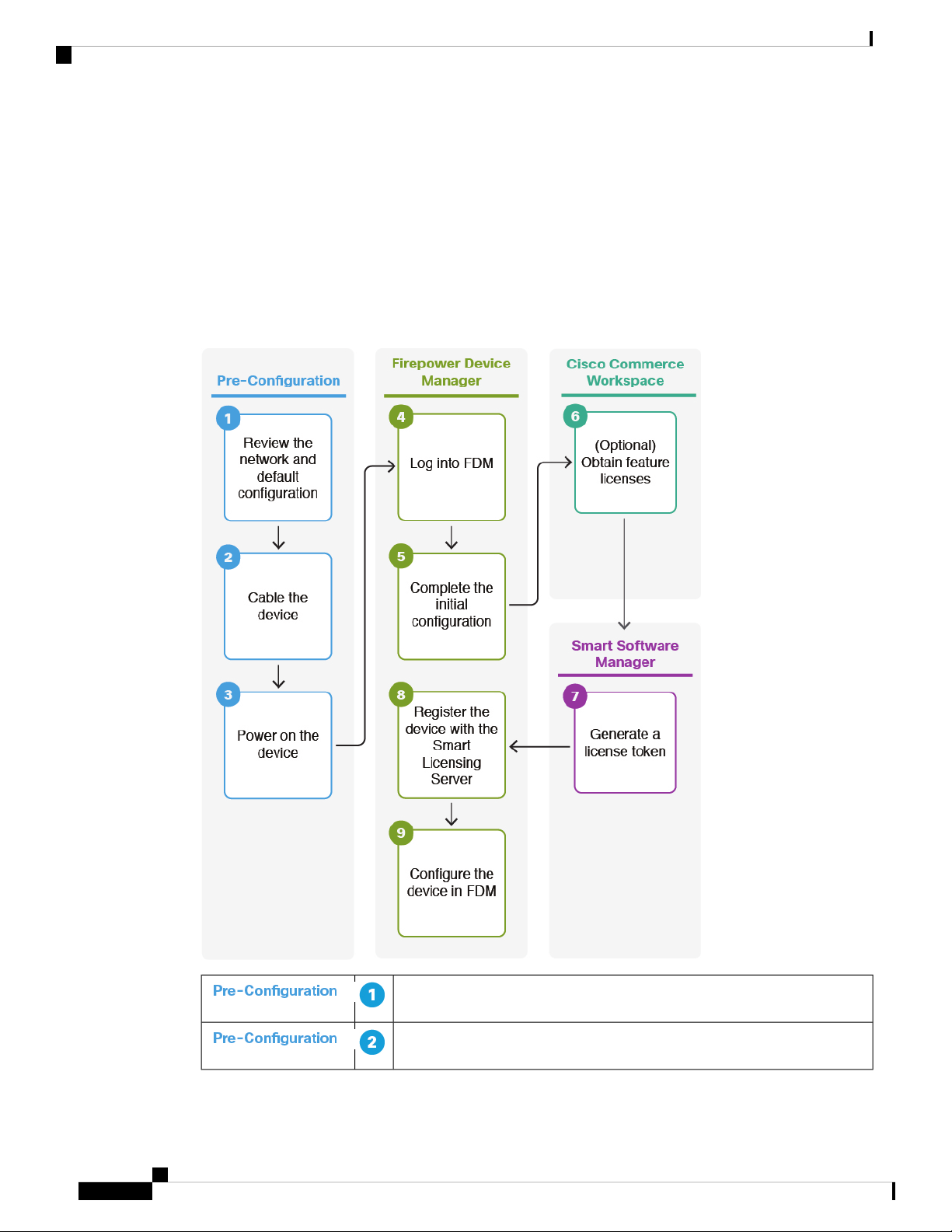
End-to-End Procedure
See the following tasks to deploy FTD with FDM on your chassis.
Firepower Threat Defense Deployment with FDM
Review the Network Deployment and Default Configuration, on page 3.
Cable the Device, on page 4.
Cisco Firepower 1100 Series Getting Started Guide
2
Page 5

Firepower Threat Defense Deployment with FDM
Review the Network Deployment and Default Configuration
Power on the Device, on page 5.
Log Into FDM, on page 6.
Complete the Initial Configuration, on page 6.
(Optional) Configure Licensing, on page 8: Obtain feature licenses.
Configure Licensing, on page 8: Generate a license token.
Configure Licensing, on page 8: Register the device with the Smart
Licensing Server.
Configure the Device in Firepower Device Manager, on page 14.
Review the Network Deployment and Default Configuration
The following figure shows the default network deployment for Firepower Threat Defense using Firepower
Device Manager on a Firepower 1100 series appliance using the default configuration.
Figure 1: Suggested Network Deployment
Firepower 1100 Series Default Configuration
For complete information about the default configuration, see the Cisco Firepower Threat Defense Configuration
Guide for Firepower Device Manager. The default configuration for the Firepower 1100 series with Firepower
Threat Defense using FDM enables the above network deployment with the following behavior:
• inside --> outside traffic flow
• outside IP address from DHCP
Cisco Firepower 1100 Series Getting Started Guide
3
Page 6

Cable the Device
Firepower Threat Defense Deployment with FDM
• DHCP for clients on inside. There is a DHCP server on the inside interface. You can plug your
management computer directly into the inside interface and get an address on the 192.168.1.0/24 network.
HTTPS access is enabled on the inside interface, so you can open FDM through the inside interface at
the default address, 192.168.1.1.
• Alternatively, you can connect to Management 1/1 to set up and manage the device using the FDM.
There is a DHCP server on the management interface. You can plug your management computer directly
into this interface and get an address on the 192.168.45.46 - 192.168.45.254 network.
HTTPS access is enabled on the management interface, so you can open FDM through the management
interface at the default address, 192.168.45.45.
Note
The physical management interface is shared between the Management logical
interface and the Diagnostic logical interface; see the Interfaces chapter of the
Cisco Firepower Threat Defense Configuration Guide for Firepower Device
Manager.
• The Firepower Threat Defense system requires Internet access for licensing and updates. The system
can obtain system database updates through the gateway for the outside interface. You do not need to
have an explicit route from the management port or network to the Internet. The default is to use internal
routes through the data interfaces.
Cable the Device
The default configuration assumes that certain interfaces are used for the inside and outside networks. Initial
configuration will be easier to complete if you connect network cables to the interfaces based on these
expectations.
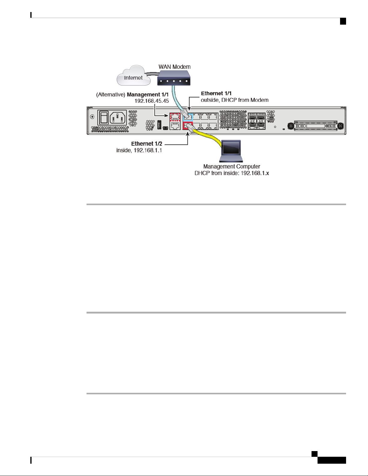
To cable the above scenario on the Firepower 1100 series see the following illustration, which shows a simple
topology using a management computer connected to the inside network. Other topologies can be used and
your deployment will vary depending on your basic logical network connectivity, ports, addressing, and
configuration requirements..
Cisco Firepower 1100 Series Getting Started Guide
4
Page 7
Firepower Threat Defense Deployment with FDM
Figure 2: Cabling the Firepower 1100 Series
Power on the Device
Procedure
Step 1 Connect the Ethernet 1/1 (outside) interface to your ISP/WAN modem or other outside device. By default,
the IP address is obtained using DHCP, but you can set a static address during initial configuration.
Step 2 Connect Ethernet 1/2 to your workstation, the one you will use to configure the device.
Step 3 Configure the workstation to obtain an IP address using DHCP. The workstation gets an address on the
192.168.1.0/24 network.
Note
You have a couple of other options for connecting the management workstation. You can also
directly connect it to the Management port. The workstation gets an address through DHCP on the
192.168.45.0/24 network. Another option is to leave your workstation attached to a switch, and
attach that switch to one of the inside ports such as Ethernet1/2. However, you must ensure that no
other device on the switch's network is running a DHCP server, because it will conflict with the one
running on the inside bridge group, 192.168.1.1.
Power on the Device
System power is controlled by a rocker power switch located on the rear of the device. The power switch is
implemented as a soft notification switch that supports graceful shutdown of the system to reduce the risk of
system software and data corruption.
Procedure
Step 1 Attach the power cord to the device, and connect it to an electrical outlet.
Step 2 Turn the power on using the standard rocker-type power on/off switch located on the rear of the chassis,
adjacent to the power cord.
Cisco Firepower 1100 Series Getting Started Guide
5
Page 8

Firepower Threat Defense Deployment with FDM
Log Into FDM
Step 3 Check the Power LED on the back of the device; if it is solid green, the device is powered on.
Step 4 Check the Status LED on the back of the device; after it is solid green, the system has passed power-on
diagnostics.
Note
Log Into FDM
Log into FDM to configure your FTD.
Before you begin
Procedure
Step 1 Enter the following URL in your browser.
When the switch is toggled from ON to OFF, it may take several seconds for the system to eventually
power off. During this time, the Power LED on the front of the chassis blinks green. Do not remove
the power until the Power LED is completely off.
• Use a current version of Firefox, Chrome, Safari, Edge, or Internet Explorer.
• https://192.168.1.1—Inside (Ethernet 1/2) interface IP address.
• https://192.168.45.45—Management interface IP address.
Step 2 Log in with the username admin, and the default password Admin123.
What to do next
• Run through the FDM initial configuration; see Complete the Initial Configuration, on page 6.
Complete the Initial Configuration
Use the setup wizard when you first log into FDM to complete the initial configuration. After you complete
the setup wizard, you should have a functioning device with a few basic policies in place:
• An outside (Ethernet1/1) and an inside interface (Ethernet1/2).
Cisco Firepower 1100 Series Getting Started Guide
6
Page 9

Firepower Threat Defense Deployment with FDM
• Security zones for the inside and outside interfaces.
• An access rule trusting all inside to outside traffic.
• An interface NAT rule that translates all inside to outside traffic to unique ports on the IP address of the
outside interface.
• A DHCP server running on the inside interface.
Procedure
Step 1 You are prompted to read and accept the End User License Agreement and change the admin password.
You must complete these steps to continue.
Step 2 Configure the following options for the outside and management interfaces and click Next.
Complete the Initial Configuration
Note
Your settings are deployed to the device when you click Next. The interface will be named “outside”
and it will be added to the “outside_zone” security zone. Ensure that your settings are correct.
a) Outside Interface—This is the data port that you connected to your gateway router. You cannot select
an alternative outside interface during initial device setup. The first data interface is the default outside
interface.
Configure IPv4—The IPv4 address for the outside interface. You can use DHCP or manually enter a
static IP address, subnet mask, and gateway. You can also select Off to not configure an IPv4 address.
Configure IPv6—The IPv6 address for the outside interface. You can use DHCP or manually enter a
static IP address, prefix, and gateway. You can also select Off to not configure an IPv6 address.
b) Management Interface
DNS Servers—The DNS server for the system's management address. Enter one or more addresses of
DNS servers for name resolution. The default is the OpenDNS public DNS servers. If you edit the fields
and want to return to the default, click Use OpenDNS to reload the appropriate IP addresses into the
fields.
Firewall Hostname—The hostname for the system's management address.
Step 3 Configure the system time settings and click Next.
a) Time Zone—Select the time zone for the system.
b) NTP Time Server—Select whether to use the default NTP servers or to manually enter the addresses of
your NTP servers. You can add multiple servers to provide backups.
Step 4 Configure the smart licenses for the system.
You must have a smart license account to obtain and apply the licenses that the system requires. Initially, you
can use the 90-day evaluation license and set up smart licensing later.
To register the device now, click the link to log into your Smart Software Manager account, and see Configure
Licensing, on page 8.
To use the evaluation license, select Start 90 day evaluation period without registration.
Step 5 Click Finish.
Cisco Firepower 1100 Series Getting Started Guide
7
Page 10

Configure Licensing
What to do next
• Although you can continue using the evaluation license, we recommend that you register and license
your device; see Configure Licensing, on page 8.
• You can also choose to configure the device; see Configure the Device in Firepower Device Manager,
on page 14.
Configure Licensing
The FTD uses Cisco Smart Software Licensing, which lets you purchase and manage a pool of licenses
centrally.
When you register the chassis, the License Authority issues an ID certificate for communication between the
chassis and the License Authority. It also assigns the chassis to the appropriate virtual account.
The Base license is included automatically. Smart Licensing does not prevent you from using product features
that you have not yet purchased, but you should purchase the following optional feature licenses to be in
compliance:
Firepower Threat Defense Deployment with FDM
• Threat—Security Intelligence and Cisco Firepower Next-Generation IPS
• Malware—Advanced Malware Protection for Networks (AMP)
• URL—URL Filtering
• RA VPN—AnyConnect Plus, AnyConnect Apex, or AnyConnect VPN Only.
In addition to the above licenses, you also need to buy a matching subscription to access updates for 1, 3, or
5 years.
For complete information on licensing your system, see the FDM configuration guide.
Before you begin
• Have a master account on the Cisco Smart Software Manager.
If you do not yet have an account, click the link to set up a new account. The Smart Software Manager
lets you create a master account for your organization.
• Your Cisco Smart Software Licensing account must qualify for the Strong Encryption (3DES/AES)
license to use some features (enabled using the export-compliance flag).
Procedure
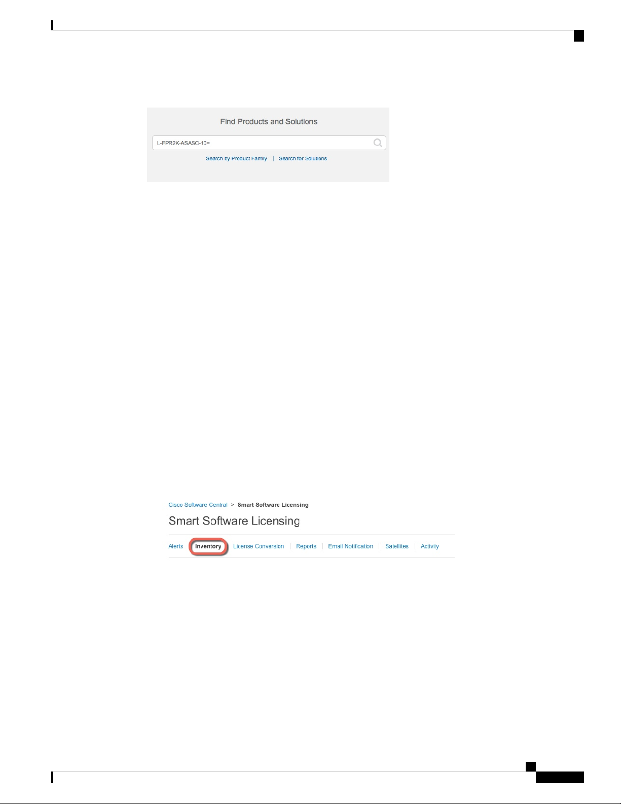
Step 1 Make sure your Smart Licensing account contains the available licenses you need.
When you bought your device from Cisco or a reseller, your licenses should have been linked to your Smart
Software License account. However, if you need to add licenses yourself, use the Find Products and Solutions
search field on the Cisco Commerce Workspace. Search for the following license PIDs:
Cisco Firepower 1100 Series Getting Started Guide
8
Page 11
Firepower Threat Defense Deployment with FDM
Figure 3: License Search
Configure Licensing
Note
If a PID is not found, you can add the PID manually to your order.
• Threat, Malware, and URL license combination:
• L-FPR1120T-TMC=
• L-FPR1140T-TMC=
• Threat, Malware, and URL subscription combination:
• L-FPR1120T-TMC-1Y
• L-FPR1120T-TMC-3Y
• L-FPR1120T-TMC-5Y
• L-FPR1140T-TMC-1Y
• L-FPR1140T-TMC-3Y
• L-FPR1140T-TMC-5Y
• RA VPN—See the Cisco AnyConnect Ordering Guide.
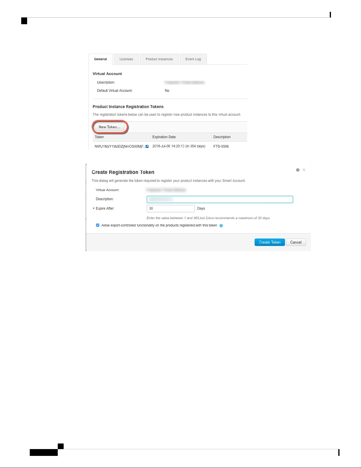
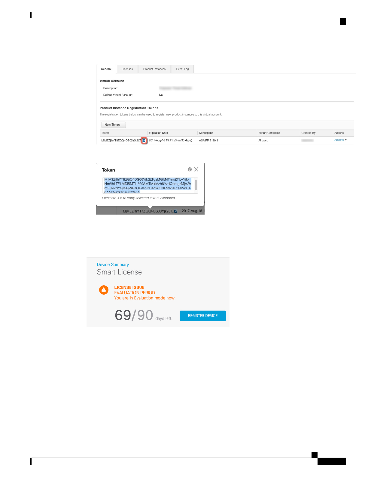
Step 2 In the Cisco Smart Software Manager, request and copy a registration token for the virtual account to which
you want to add this device.
a) Click Inventory.
b) On the General tab, click New Token.
Cisco Firepower 1100 Series Getting Started Guide
9
Page 12
Configure Licensing
Firepower Threat Defense Deployment with FDM
c) On the Create Registration Token dialog box enter the following settings, and then click Create Token:
• Description
• Expire After—Cisco recommends 30 days.
• Allow export-controlled functionaility on the products registered with this token—Enables the
export-compliance flag.
The token is added to your inventory.
d) Click the arrow icon to the right of the token to open the Token dialog box so you can copy the token ID
to your clipboard. Keep this token ready for later in the procedure when you need to register the ASA.
Cisco Firepower 1100 Series Getting Started Guide
10
Page 13
Firepower Threat Defense Deployment with FDM
Figure 4: View Token
Figure 5: Copy Token
Configure Licensing
Step 3 In FDM, click Device, and then in the Smart License summary, click View Configuration.
You see the Smart License page.
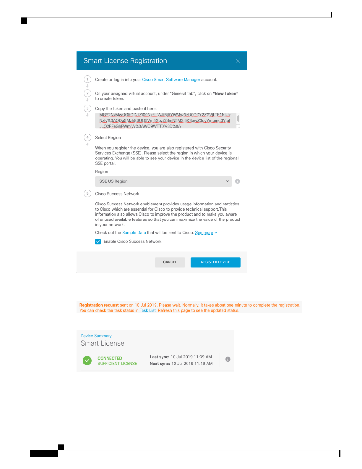
Step 4 Click Register Device.
Then follow the instructions on the Smart License Registration dialog box to paste in your token.:
Cisco Firepower 1100 Series Getting Started Guide
11
Page 14
Configure Licensing
Firepower Threat Defense Deployment with FDM
Step 5 Click Register Device.
You return to the Smart License page. While the device registers, you see the following message:
After the device successfully registers and you refresh the page, you see the following:
Step 6 Click the Enable/Disable control for each optional license as desired.
Cisco Firepower 1100 Series Getting Started Guide
12
Page 15

Firepower Threat Defense Deployment with FDM
• Enable—Registers the license with your Cisco Smart Software Manager account and enables the controlled
features. You can now configure and deploy policies controlled by the license.
• Disable—Unregisters the license with your Cisco Smart Software Manager account and disables the
controlled features. You cannot configure the features in new policies, nor can you deploy policies that
use the feature.
Configure Licensing
• If you enabled the RA VPN license, select the type of license you want to use: Plus, Apex, VPN Only,
or Plus and Apex.
After you enable features, if you do not have the licenses in your account, you will see the following
non-compliance message after you refresh the page:
Step 7 Choose Resync Connection from the gear drop-down list to synchronize license information with Cisco
Smart Software Manager.
Cisco Firepower 1100 Series Getting Started Guide
13
Page 16

Firepower Threat Defense Deployment with FDM
Configure the Device in Firepower Device Manager
Configure the Device in Firepower Device Manager
The following steps provide an overview of additional features you might want to configure. Please click the
help button (?) on a page to get detailed information about each step.
Procedure
Step 1 If you wired other interfaces, choose Device, and then click the link in the Interfaces summary.
Click the edit icon ( ) for each interface to set the mode and define the IP address and other settings.
The following example configures an interface to be used as a “demilitarized zone” (DMZ), where you place
publically-accessible assets such as your web server. Click Save when you are finished.
Figure 6: Edit Interface
Step 2 If you configured new interfaces, choose Objects, then select Security Zones from the table of contents.
Edit or create new zones as appropriate. Each interface must belong to a zone, because you configure policies
based on security zones, not interfaces. You cannot put the interfaces in zones when configuring them, so you
must always edit the zone objects after creating new interfaces or changing the purpose of existing interfaces.
The following example shows how to create a new dmz-zone for the dmz interface.
Cisco Firepower 1100 Series Getting Started Guide
14
Page 17

Firepower Threat Defense Deployment with FDM
Figure 7: Security Zone Object
Step 3 If you want internal clients to use DHCP to obtain an IP address from the device, choose Device > System
Settings > DHCP Server, then select the DHCP Servers tab.
There is already a DHCP server configured for the inside interface, but you can edit the address pool or even
delete it. If you configured other inside interfaces, it is very typical to set up a DHCP server on those interfaces.
Click + to configure the server and address pool for each inside interface.
Configure the Device in Firepower Device Manager
You can also fine-tune the WINS and DNS list supplied to clients on the Configuration tab. The following
example shows how to set up a DHCP server on the inside2 interface with the address pool
192.168.4.50-192.168.4.240.
Figure 8: DHCP Server
Step 4 Choose Device, then click View Configuration (or Create First Static Route) in the Routing group and
configure a default route.
The default route normally points to the upstream or ISP router that resides off the outside interface. A default
IPv4 route is for any-ipv4 (0.0.0.0/0), whereas a default IPv6 route is for any-ipv6 (::0/0). Create routes for
each IP version you use. If you use DHCP to obtain an address for the outside interface, you might already
have the default routes that you need.
Note
The routes you define on this page are for the data interfaces only. They do not impact the
management interface. Set the management gateway on Device > System Settings > Management
Interface.
Cisco Firepower 1100 Series Getting Started Guide
15
Page 18

Configure the Device in Firepower Device Manager
The following example shows a default route for IPv4. In this example, isp-gateway is a network object that
identifies the IP address of the ISP gateway (you must obtain the address from your ISP). You can create this
object by clicking Create New Network at the bottom of the Gateway drop-down list.
Figure 9: Default Route
Firepower Threat Defense Deployment with FDM
Step 5 Choose Policies and configure the security policies for the network.
The device setup wizard enables traffic flow between the inside-zone and outside-zone, and interface NAT
for all interfaces when going to the outside interface. Even if you configure new interfaces, if you add them
to the inside-zone object, the access control rule automatically applies to them.
However, if you have multiple inside interfaces, you need an access control rule to allow traffic flow from
inside-zone to inside-zone. If you add other security zones, you need rules to allow traffic to and from those
zones. These would be your minimum changes.
In addition, you can configure other policies to provide additional services, and fine-tune NAT and access
rules to get the results that your organization requires. You can configure the following policies:
• SSL Decryption—If you want to inspect encrypted connections (such as HTTPS) for intrusions, malware,
and so forth, you must decrypt the connections. Use the SSL decryption policy to determine which
connections need to be decrypted. The system re-encrypts the connection after inspecting it.
• Identity—If you want to correlate network activity to individual users, or control network access based
on user or user group membership, use the identity policy to determine the user associated with a given
source IP address.
• Security Intelligence—Use the Security Intelligence policy to quickly drop connections from or to
blacklisted IP addresses or URLs. By blacklisting known bad sites, you do not need to account for them
in your access control policy. Cisco provides regularly updated feeds of known bad addresses and URLs
so that the Security Intelligence blacklist updates dynamically. Using feeds, you do not need to edit the
policy to add or remove items in the blacklist.
• NAT (Network Address Translation)—Use the NAT policy to convert internal IP addresses to externally
routeable addresses.
Cisco Firepower 1100 Series Getting Started Guide
16
Page 19

Firepower Threat Defense Deployment with FDM
• Access Control—Use the access control policy to determine which connections are allowed on the
network. You can filter by security zone, IP address, protocol, port, application, URL, user or user group.
You also apply intrusion and file (malware) policies using access control rules. Use this policy to
implement URL filtering.
• Intrusion—Use the intrusion policies to inspect for known threats. Although you apply intrusion policies
using access control rules, you can edit the intrusion policies to selectively enable or disable specific
intrusion rules.
The following example shows how to allow traffic between the inside-zone and dmz-zone in the access control
policy. In this example, no options are set on any of the other tabs except for Logging, where At End of
Connection is selected.
Figure 10: Access Control Policy
Access the FTD and FXOS CLI
Step 6 Choose Device, then click View Configuration in the Updates group and configure the update schedules for
the system databases.
If you are using intrusion policies, set up regular updates for the Rules and VDB databases. If you use Security
Intelligence feeds, set an update schedule for them. If you use geolocation in any security policies as matching
criteria, set an update schedule for that database.
Step 7 Click the Deploy button in the menu, then click the Deploy Now button ( ), to deploy your changes to
the device.
Changes are not active on the device until you deploy them.
Access the FTD and FXOS CLI
Use the command-line interface (CLI) to set up the system and do basic system troubleshooting. You cannot
configure policies through a CLI session. You can access the CLI by connecting to the console port.
You can SSH to the management interface of the FTD device. You can also connect to the address on a data
interface if you open the interface for SSH connections. SSH access to data interfaces is disabled by default.
You can also access the FXOS CLI from the FTD CLI for troubleshooting purposes.
Cisco Firepower 1100 Series Getting Started Guide
17
Page 20

Firepower Threat Defense Deployment with FDM
Access the FTD and FXOS CLI
Procedure
Step 1 To log into the CLI, connect your management computer to the console port. See the hardware guide for your
device for more information about the console cable. Use the following serial settings:
• 9600 baud
• 8 data bits
• No parity
• 1 stop bit
Attention
The CLI on the console port is FXOS.
Step 2 At the prompt, log into the FXOS CLI.
Example:
firepower login: admin
Password:
Last login: Thu May 16 14:01:03 UTC 2019 on ttyS0
Successful login attempts for user 'admin' : 1
firepower#
Step 3 Access the FTD CLI.
connect ftd
Example:
firepower# connect ftd
>
After logging in, for information on the commands available in the CLI, enter help or ?. For usage information,
see the Cisco Firepower Threat Defense Command Reference.
Step 4 To exit the FTD CLI, enter the exit or logout command.
Example:
> exit
firepower#
Note
This returns you to the FXOS CLI prompt. For information on the commands available in the FXOS
CLI, enter ?. For usage information, see the Cisco Firepower FXOS Command Reference.
Cisco Firepower 1100 Series Getting Started Guide
18
Page 21

Firepower Threat Defense Deployment with FDM
Power Off the Device
It's important that you shut down your system properly using the FTD CLI. Simply unplugging the power or
pressing the power switch can cause serious file system damage. Remember that there are many processes
running in the background all the time, and unplugging or shutting off the power does not allow the graceful
shutdown of your Firepower System.
If you need to power off your Firepower device, follow the procedure in this topic.
Note
This procedure assumes that you completed the initial setup process using the default admin user for the
initial login.
Before you begin
Before you power off the Firepower device:
Power Off the Device
• Determine if you need to shut down or disconnect any devices connected to the Firepower network data
ports.
• Review the hardware guide for your device for complete information about the chassis components,
including the location of the management port, console port, power supply, and related LED information.
Procedure
Step 1 Connect the management computer to the management port or console port of the chassis to access the FTD
CLI.
Step 2 Connect to the FTD CLI, either from the console port or using SSH.
• You can SSH to the management interface of the FTD device. You can also connect to the address on a
data interface if you open the interface for SSH connections. SSH access to data interfaces is disabled
by default.
• You can directly connect to the console port on the device. Use the console cable included with the device
to connect your PC to the console using a terminal emulator set for 9600 baud, 8 data bits, no parity, 1
stop bit, no flow control. See the hardware guide for your device for more information about the console
cable.
Step 3 Log in with the admin username and password.
Note
The CLI on the console port is FXOS. You can get to the FTD CLI using the connect ftd command.
Use the FXOS CLI for chassis-level configuration and troubleshooting only. Use the FTD CLI for
basic configuration, monitoring, and normal system troubleshooting. See the FXOS documentation
for information on FXOS commands.
Step 4 To power off the device, use the shutdown command at the CLI prompt (>):
Example:
> shutdown
This command will shutdown the system. Continue?
Please enter 'YES' or 'NO': YES
Cisco Firepower 1100 Series Getting Started Guide
19
Page 22

What's Next
The command will gracefully shut down the Firepower System.
Step 5 Observe the Power LED and Status LED to verify that the chassis is powered off (appear unlit).
Step 6 After the chassis has successfully powered off, you can then unplug the power to physically remove power
from the chassis if necessary.
What's Next
To continue configuring your Firepower Threat Defense device, see the documents available for your software
version at Navigating the Cisco Firepower Documentation.
For information related to using Firepower Device Manager, see Cisco Firepower Threat Defense Configuration
Guide for Firepower Device Manager.
Firepower Threat Defense Deployment with FDM
Cisco Firepower 1100 Series Getting Started Guide
20
Page 23

CHAPTER 2
Firepower Threat Defense Deployment with FMC
The Cisco Firepower 1100 Series is a standalone modular security services platform that includes the Firepower
1120 and Firepower 1140 security appliances. This chapter describes how to deploy the Cisco Firepower 1100
Series security appliance running Firepower software with Firepower Management Center (FMC).
Important
Note
The Firepower 1100 Series supports Cisco Firepower software version 6.4 and later.
Privacy Collection Statement—The Firepower 1100 Series does not require or actively collect
personally-identifiable information. However, you can use personally-identifiable information in the
configuration, for example for usernames. In this case, an administrator might be able to see this information
when working with the configuration or when using SNMP.
• Is This Chapter for You?, on page 21
• Before You Start, on page 22
• End-to-End Procedure, on page 22
• Review the Network Deployment, on page 23
• Cable the Device, on page 25
• Power on the Device, on page 27
• Configure the Device for Firepower Management, on page 27
• Log Into the Firepower Management Center, on page 31
• Obtain Licenses for the Firepower Management Center, on page 31
• Register the Firepower Threat Defense with the Firepower Management Center, on page 32
• Configure a Basic Security Policy, on page 34
• Access the FTD and FXOS CLI, on page 44
• Power Off the Device, on page 45
Is This Chapter for You?
This chapter explains how to complete the initial configuration of your Firepower Threat Defense (FTD) and
how to register the device to a Firepower Management Center (FMC). In a typical deployment on a large
network, multiple managed devices are installed on network segments, monitor traffic for analysis, and report
Cisco Firepower 1100 Series Getting Started Guide
21
Page 24

Before You Start
to a managing FMC, which provides a centralized management console with web interface that you can use
to perform administrative, management, analysis, and reporting tasks.
For networks that include only a single device or just a few, where you do not need to use a high-powered
multiple-device manager like the FMC, you can use the integrated Firepower Device Manager (FDM). Use
the FDM web-based device setup wizard to configure the basic features of the software that are most commonly
used for small network deployments.
Before You Start
Deploy and perform initial configuration of the FMC. See the FMC getting started guide.
Note
The Firepower 1010 and the FMC both have the same default management IP address: 192.168.45.45. This
guide assumes that you will set different IP addresses for your devices during initial setup.
Firepower Threat Defense Deployment with FMC
End-to-End Procedure
See the following tasks to deploy the FTD with FMC on your chassis.
Review the Network Deployment, on page 23.
Cisco Firepower 1100 Series Getting Started Guide
22
Page 25

Firepower Threat Defense Deployment with FMC
Review the Network Deployment
Cable the Device, on page 25.
Power on the Device, on page 27.
Configure the Device for Firepower Management, on page 27.
Log Into the Firepower Management Center, on page 31.
Obtain Licenses for the Firepower Management Center, on page 31: Buy
feature licenses.
Obtain Licenses for the Firepower Management Center, on page 31:
1. Generate a license token for the FMC.
2. Register the FMC with the Smart Licensing server.
Register the Firepower Threat Defense with the Firepower Management
Center, on page 32.
Configure a Basic Security Policy, on page 34.
Review the Network Deployment
By default, only the Management 1/1 interface is enabled and configured with an IP address (192.168.45.45).
You can configure other interfaces after you connect the FTD to FMC.
Separate Management Network
The FMC can only communicate with the FTD on the management interface. Moreover, both the FMC and
FTD require internet access from management for licensing and updates.
The following figure shows a possible network deployment for the Firepower 1100 where the FMC and
management computer connect to the management network. The management network has a path to the
internet for licensing and updates.
Cisco Firepower 1100 Series Getting Started Guide
23
Page 26

Review the Network Deployment
Figure 11: Separate Management Network
Firepower Threat Defense Deployment with FMC
FTD as Internet Gateway
The FMC can only communicate with the FTD on the management interface. Moreover, both the FMC and
FTD require internet access from management for licensing and updates.
The following figure shows a possible network deployment for the Firepower 1100 where the Firepower 1100
acts as the internet gateway for the FMC and FTD managamement.
In the following diagram, the Firepower 1100 acts as the internet gateway for the management interface and
the FMC by connecting Management 1/1 to an inside interface through a Layer 2 switch, and by connecting
the FMC and management computer to the switch. (This direct connection is allowed because the management
interface is separate from the other interfaces on the FTD.)
Cisco Firepower 1100 Series Getting Started Guide
24
Page 27

Firepower Threat Defense Deployment with FMC
Figure 12: Edge Network Deployment
Cable the Device
Cable the Device
To cable one of the above scenarios on the Firepower 1100, see the following steps.
Note
The Firepower 1010 and the FMC both have the same default management IP address: 192.168.45.45. This
guide assumes that you will set different IP addresses for your devices during initial setup.
Note
Other topologies can be used, and your deployment will vary depending on your basic logical network
connectivity, ports, addressing, and configuration requirements.
Procedure
Step 1 Cable for a separate management network:
Cisco Firepower 1100 Series Getting Started Guide
25
Page 28

Cable the Device
Firepower Threat Defense Deployment with FMC
Figure 13: Cabling a Separate Management Network
a) Cable the following to your management network:
• Management 1/1 interface
• Firepower Management Center
• Management computer
b) Connect the inside interface (for example, Ethernet 1/2) to your inside router.
c) Connect the outside interface (for example, Ethernet 1/1) to your outside router.
d) Connect other networks to the remaining interfaces.
Step 2 Cable for an edge deployment:
Figure 14: Cabling an Edge Deployment
Cisco Firepower 1100 Series Getting Started Guide
26
Page 29

Firepower Threat Defense Deployment with FMC
a) Cable the following to a Layer 2 Ethernet switch:
• Inside interface (for example, Ethernet 1/2)
• Management 1/1 interface
• Firepower Management Center
• Management computer
b) Connect the outside interface (for example, Ethernet 1/1) to your outside router.
c) Connect other networks to the remaining interfaces.
Power on the Device
System power is controlled by a rocker power switch located on the rear of the device. The power switch is
implemented as a soft notification switch that supports graceful shutdown of the system to reduce the risk of
system software and data corruption.
Power on the Device
Procedure
Step 1 Attach the power cord to the device, and connect it to an electrical outlet.
Step 2 Turn the power on using the standard rocker-type power on/off switch located on the rear of the chassis,
adjacent to the power cord.
Step 3 Check the Power LED on the back of the device; if it is solid green, the device is powered on.
Step 4 Check the Status LED on the back of the device; after it is solid green, the system has passed power-on
diagnostics.
Note
When the switch is toggled from ON to OFF, it may take several seconds for the system to eventually
power off. During this time, the Power LED on the front of the chassis blinks green. Do not remove
the power until the Power LED is completely off.
Configure the Device for Firepower Management
The first time you access the CLI, a setup wizard prompts you for basic network configuration parameters
that are required to setup your Firepower Threat Defense device and to register with a Firepower Management
Center (FMC). Note that the management IP address and associated gateway route are not included on theFMC
Cisco Firepower 1100 Series Getting Started Guide
27
Page 30

Configure the Device for Firepower Management
web interface in the list of interfaces or static routes for the device; they can only be set by the setup script
and at the CLI.
Before you begin
• Ensure that you connect a data interface to your gateway device, for example, a cable modem or router.
For edge deployments, this would be your Internet-facing gateway. For data center deployments, this
would be a back-bone router.
• The Management interface must also be connected to a gateway through which the Internet is accessible.
System licensing and database updates require Internet access.
Procedure
Step 1 Connect to the device, either from the console port or using SSH, for example.
• For a device attached to a monitor and keyboard, log in at the console.
• For access to the management interface of the device, SSH to the Management interface’s default IPv4
address: 192.168.45.45.
Firepower Threat Defense Deployment with FMC
Step 2 Log in with the username admin and the password Admin123.
Step 3 When the Firepower Threat Defense system boots, a setup wizard prompts you for the following information
required to configure the system:
• Accept EULA
• New admin password
• IPv4 or IPv6 configuration
• IPv4 or IPv6 DHCP settings
• Management port IPv4 address and subnet mask, or IPv6 address and prefix.
You can enable a DHCP server on the Management 1/1 interface to provide IP addresses to the
management PC and other management devices.
• System name
• Default gateway IPv4, IPv6, or both.
In the sample configuration above, identify the planned inside interface IP address as the gateway address.
You will set this and other interface IP addresses in the FMC later. If the FMC is on a separate internal
network, then identify the internal router IP address as the gateway, depending on your network setup.
• DNS setup
• HTTP proxy
• Management mode
You are asked if you want to manage the device locally (using Firepower Device Manager). Answer no
to use the FMC.
Cisco Firepower 1100 Series Getting Started Guide
28
Page 31

Firepower Threat Defense Deployment with FMC
Step 4 Review the setup wizard settings. Defaults or previously entered values appear in brackets. To accept previously
entered values, press Enter.
Example:
Please enter 'YES' or press <ENTER> to AGREE to the EULA:
System initialization in progress. Please stand by.
You must change the password for 'admin' to continue.
Enter new password:
Confirm new password:
You must configure the network to continue.
You must configure at least one of IPv4 or IPv6.
Do you want to configure IPv4? (y/n) [y]: y
Do you want to configure IPv6? (y/n) [n]: n
Configure IPv4 via DHCP or manually? (dhcp/manual) [manual]: manual
Enter an IPv4 address for the management interface [192.168.45.45]: 10.133.128.47
Enter an IPv4 netmask for the management interface [255.255.255.0]: 255.255.248.0
Enter the IPv4 default gateway for the management interface []: 10.133.128.1
Enter a fully qualified hostname for this system [firepower]: laurel.example.com
Enter a comma-separated list of DNS servers or 'none' []: 10.33.16.6
Enter a comma-separated list of search domains or 'none' []:
If your networking information has changed, you will need to reconnect.
Configure the Device for Firepower Management
For HTTP Proxy configuration, run 'configure network http-proxy'
Manage the device locally? (yes/no) [yes]: no
Step 5 Reconnect to your appliance using the new log in credentials.
Step 6 Configure the firewall mode. For example:
Example:
Configure firewall mode? (routed/transparent) [routed]
Note
We recommend that you set the firewall mode at initial configuration. Note that the default mode
is routed. Changing the firewall mode after initial setup erases your running configuration. For
more information, see the chapter “Transparent or Routed Firewall Mode for Firepower Threat
Defense” in the Firepower Management Center Configuration Guide
Step 7 Wait for the default system configuration to be processed. This may take a few minutes.
Example:
Update policy deployment information
- add device configuration
You can register the sensor to a Management Center and use the Management Center
to manage it. Note that registering the sensor to a Management Center disables
on-sensor FirePOWER Services management capabilities.
When registering the sensor to a Management Center, a unique alphanumeric
registration key is always required. In most cases, to register a sensor
to a Management Center, you must provide the hostname or the IP address along
with the registration key.
'configure manager add [hostname | ip address ] [registration key ]'
However, if the sensor and the Management Center are separated by a NAT device,
you must enter a unique NAT ID, along with the unique registration key.
'configure manager add DONTRESOLVE [registration key ] [ NAT ID ]'
Cisco Firepower 1100 Series Getting Started Guide
29
Page 32

Configure the Device for Firepower Management
Later, using the web interface on the Management Center, you must use the same
registration key and, if necessary, the same NAT ID when you add this
sensor to the Management Center.
Step 8 Register the Firepower Threat Defense device to the managing FMC:
Example:
> configure manager add {hostname | IPv4_address | IPv6_address | DONTRESOLVE} reg_key
[nat_id]
where:
• {hostname | IPv4_address | IPv6_address | DONTRESOLVE} specifies either the fully qualified host
name or IP address of theFMC. If the FMC is not directly addressable, use DONTRESOLVE.
• reg_key is the unique alphanumeric registration key required to register the device to the FMC.
Firepower Threat Defense Deployment with FMC
Note
The registration key is a user-generated one-time use key that must not exceed 37 characters.
Valid characters include alphanumerical characters (A–Z, a–z, 0–9) and the hyphen (-). You
will need to remember this registration key when you add the device to the FMC.
• nat_id is an optional alphanumeric string used during the registration process between the FMC and the
device when one side does not specify an IP address. It is required if the hostname is set to
DONTRESOLVE. Enter the same NAT ID on the FMC.
Note
The NAT ID is a user-generated one-time use key that must not exceed 37 characters. Valid
characters include alphanumerical characters (A–Z, a–z, 0–9) and the hyphen (-). You will
need to remember this ID when you add the device to the FMC.
Example:
> configure manager add MC.example.com 123456
Manager successfully configured.
If the Firepower Threat Defense device and the FMC are separated by a NAT device, enter a unique NAT ID
along with the registration key, and specify DONTRESOLVE instead of the hostname, for example:
Example:
> configure manager add DONTRESOLVE my_reg_key my_nat_id
Manager successfully configured.
The FMC and the device use the registration key and NAT ID (instead of IP addresses) to authenticate and
authorize for initial registration. The NAT ID must be unique among all NAT IDs used to register managed
appliances to establish trust for the initial communication and to look up the correct registration key.
Note
Step 9 Close the CLI.
Example:
> exit
Cisco Firepower 1100 Series Getting Started Guide
30
At least one of the security appliances, either the FMC or the Firepower Threat Defense, must have
a public IP address to establish the two-way, SSL-encrypted communication channel between the
two appliances.
Page 33

Firepower Threat Defense Deployment with FMC
What to do next
Register your device to a FMC as described in the next section.
Log Into the Firepower Management Center
Use the FMC to configure and monitor the FTD.
Before you begin
For information on supported browsers, refer to the release notes for the version you are using (see
https://www.cisco.com/go/firepower-notes).
Procedure
Step 1 Using a supported browser, enter the following URL.
https://fmc_ip_address
Log Into the Firepower Management Center
• fmc_ip_address—Identifies the IP address or host name of the FMC.
Step 2 Enter your username and password.
Step 3 Click Log In.
Obtain Licenses for the Firepower Management Center
All licenses are supplied to the FTD by the FMC. You can optionally purchase the following feature licenses:
• Threat—Security Intelligence and Cisco Firepower Next-Generation IPS
• Malware—Advanced Malware Protection for Networks (AMP)
• URL—URL Filtering
• RA VPN—AnyConnect Plus, AnyConnect Apex, or AnyConnect VPN Only.
In addition to the above licenses, you also need to buy a matching subscription to access updates for 1, 3, or
5 years.
Before you begin
• Have a master account on the Cisco Smart Software Manager.
If you do not yet have an account, click the link to set up a new account. The Smart Software Manager
lets you create a master account for your organization.
• Your Cisco Smart Software Licensing account must qualify for the Strong Encryption (3DES/AES)
license to use some features (enabled using the export-compliance flag).
Cisco Firepower 1100 Series Getting Started Guide
31
Page 34

Firepower Threat Defense Deployment with FMC
Register the Firepower Threat Defense with the Firepower Management Center
Procedure
Step 1 Make sure your Smart Licensing account contains the available licenses you need.
When you bought your device from Cisco or a reseller, your licenses should have been linked to your Smart
Software License account. However, if you need to add licenses yourself, use the Find Products and Solutions
search field on the Cisco Commerce Workspace. Search for the following license PIDs:
Figure 15: License Search
Note
Step 2 If you have not already done so, register the FMC with the Smart Licensing server.
Registering requires you to generate a registration token in the Smart Software Manager. See the FMC
configuration guide for detailed instructions.
If a PID is not found, you can add the PID manually to your order.
• Threat, Malware, and URL license combination:
• L-FPR1120T-TMC=
• L-FPR1140T-TMC=
• Threat, Malware, and URL subscription combination:
• L-FPR1120T-TMC-1Y
• L-FPR1120T-TMC-3Y
• L-FPR1120T-TMC-5Y
• L-FPR1140T-TMC-1Y
• L-FPR1140T-TMC-3Y
• L-FPR1140T-TMC-5Y
• RA VPN—See the Cisco AnyConnect Ordering Guide.
Register the Firepower Threat Defense with the Firepower
Management Center
Register the FTD to the FMC.
Cisco Firepower 1100 Series Getting Started Guide
32
Page 35

Firepower Threat Defense Deployment with FMC
Before you begin
• Gather the following information that you set in the FTD initial configuration:
• FTD management IP address and/or NAT ID
• FMC registration key
Procedure
Step 1 In FMC, choose Devices > Device Management.
Step 2 From the Add drop-down list, choose Add Device, and enter the following parameters.
Register the Firepower Threat Defense with the Firepower Management Center
• Host—Enter the IP address of the FTD you want to add. You can leave this field blank if you specified
both the FMC IP address and a NAT ID in the FTD initial configuration.
• Display Name—Enter the name for the FTD as you want it to display in the FMC.
• Registration Key—Enter the same registration key that you specified in the FTD initial configuration.
• Domain—Assign the device to a leaf domain if you have a multidomain environment.
• Group—Assign it to a device group if you are using groups.
• Access Control Policy—Choose an initial policy. Unless you already have a customized policy you
know you need to use, choose Create new policy, and choose Block all traffic. You can change this
later to allow traffic; see Configure Access Control, on page 42.
Cisco Firepower 1100 Series Getting Started Guide
33
Page 36

Configure a Basic Security Policy
• Smart Licensing—Assign the Smart Licenses you need for the features you want to deploy: Malware
(if you intend to use AMP malware inspection), Threat (if you intend to use intrusion prevention), and
URL (if you intend to implement category-based URL filtering).
• Unique NAT ID—Specify the NAT ID you specified in the FTD initial configuration.
• Transfer Packets—Allow the device to transfer packets to the FMC. When events like IPS or Snort are
triggered with this option enabled, the device sends event metadata information and packet data to the
FMC for inspection. If you disable it, only event information will be sent to the FMC, but packet data is
not sent.
Firepower Threat Defense Deployment with FMC
Step 3 Click Register, and confirm a successful registration.
If the registration succeeds, the device is added to the list. If it fails, you will see an error message. If the FTD
fails to register, check the following items:
• Ping—Access the FTD CLI, and ping the FMC IP address using the following command:
ping system ip_address
If the ping is not successful, check your network settings using the show network command. If you need
to change the FTD IP address, use the configure network {ipv4 | ipv6} manual command.
• Registration key, NAT ID, and FMC IP address—Make sure you are using the same registration key,
and if used, NAT ID, on both devices. You can set the registration key and NAT ID on the FTD using
the configure manager add command. This command also lets you change the FMC IP address.
Configure a Basic Security Policy
This section describes how to configure a basic security policy with the following settings:
• Inside and outside interfaces—Assign a static IP address to the inside interface, and use DHCP for the
outside interface.
• DHCP server—Use a DHCP server on the inside interface for clients.
• Default route—Add a default route through the outside interface.
• NAT—Use interface PAT on the outside interface.
• Access control—Allow traffic from inside to outside.
Cisco Firepower 1100 Series Getting Started Guide
34
Page 37

Firepower Threat Defense Deployment with FMC
To configure a basic security policy, complete the following tasks.
Configure Interfaces
Enable FTD interfaces, assign them to security zones, and set the IP addresses. Typically, you must configure
at least a minimum of two interfaces to have a system that passes meaningful traffic. Normally, you would
have an outside interface that faces the upstream router or internet, and one or more inside interfaces for your
organization’s networks. Some of these interfaces might be “demilitarized zones” (DMZs), where you place
publically-accessible assets such as your web server.
Configure Interfaces
Configure Interfaces, on page 35.Step 1
Configure the DHCP Server, on page 38.Step 2
Add the Default Route, on page 39.Step 3
Configure NAT, on page 40.Step 4
Configure Access Control, on page 42.Step 5
Deploy the Configuration, on page 43.Step 6
A typical edge-routing situation is to obtain the outside interface address through DHCP from your ISP, while
you define static addresses on the inside interfaces.
The following example configures a routed mode inside interface with a static address and a routed mode
outside interface using DHCP.
Procedure
Step 1 Choose Devices > Device Management, and click the edit icon ( ) for the device.
Step 2 Click Interfaces.
Step 3 Click the edit icon ( ) for the interface that you want to use for inside.
The General tab appears.
Cisco Firepower 1100 Series Getting Started Guide
35
Page 38

Configure Interfaces
Firepower Threat Defense Deployment with FMC
a) Enter a Name up to 48 characters in length.
For example, name the interface inside.
b) Check the Enabled check box.
c) Leave the Mode set to None.
d) From the Security Zone drop-down list, choose an existing inside security zone or add a new one by
clicking New.
For example, add a zone called inside_zone. Each interface must be assigned to a security zone and/or
interface group. An interface can belong to only one security zone, but can also belong to multiple interface
groups. You apply your security policy based on zones or groups. For example, you can assign the inside
interface to the inside zone; and the outside interface to the outside zone. Then you can configure your
access control policy to enable traffic to go from inside to outside, but not from outside to inside. Most
policies only support security zones; you can use zones or interface groups in NAT policies, prefilter
policies, and QoS policies.
e) Click the IPv4 and/or IPv6 tab.
• IPv4—Choose Use Static IP from the drop-down list, and enter an IP address and subnet mask in
slash notation.
For example, enter 192.168.1.1/24
Cisco Firepower 1100 Series Getting Started Guide
36
Page 39

Firepower Threat Defense Deployment with FMC
• IPv6—Check the Autoconfiguration check box for stateless autoconfiguration.
f) Click OK.
Step 4 Click the edit icon ( ) for the interface that you want to use for outside.
The General tab appears.
Configure Interfaces
a) Enter a Name up to 48 characters in length.
For example, name the interface outside.
b) Check the Enabled check box.
c) Leave the Mode set to None.
d) From the Security Zone drop-down list, choose an existing outside security zone or add a new one by
clicking New.
For example, add a zone called outside_zone.
e) Click the IPv4 and/or IPv6 tab.
• IPv4—Choose Use DHCP, and configure the following optional parameters:
• Obtain default route using DHCP—Obtains the default route from the DHCP server.
• DHCP route metric—Assigns an administrative distance to the learned route, between 1 and
255. The default administrative distance for the learned routes is 1.
Cisco Firepower 1100 Series Getting Started Guide
37
Page 40

Configure the DHCP Server
f) Click OK.
Step 5 Click Save.
Firepower Threat Defense Deployment with FMC
• IPv6—Check the Autoconfiguration check box for stateless autoconfiguration.
Configure the DHCP Server
Enable the DHCP server if you want clients to use DHCP to obtain IP addresses from the FTD.
Procedure
Step 1 Choose Devices > Device Management, and click the edit icon ( ) for the device.
Step 2 Choose DHCP > DHCP Server.
Step 3 On the Server page, click Add, and configure the following options:
• Interface—Choose the interface from the drop-down list.
• Address Pool—Set the range of IP addresses from lowest to highest that are used by the DHCP server.
The range of IP addresses must be on the same subnet as the selected interface and cannot include the
IP address of the interface itself.
• Enable DHCP Server—Enable the DHCP server on the selected interface.
Step 4 Click OK.
Step 5 Click Save.
Cisco Firepower 1100 Series Getting Started Guide
38
Page 41

Firepower Threat Defense Deployment with FMC
Add the Default Route
The default route normally points to the upstream router reachable from the outside interface. If you use DHCP
for the outside interface, your device might have already received a default route. If you need to manually
add the route, complete this procedure. If you received a default route from the DHCP server, it will show in
the IPv4 Routes or IPv6 Routes table on the Devices > Device Management > Routing > Static Route
page.
Procedure
Step 1 Choose Devices > Device Management, and click the edit icon ( ) for the device.
Step 2 Choose Routing > Static Route, click Add Route, and set the following:
Add the Default Route
• Type—Click the IPv4 or IPv6 radio button depending on the type of static route that you are adding.
• Interface—Choose the egress interface; typically the outside interface.
• Available Network—Choose any-ipv4 for an IPv4 default route, or any-ipv6 for an IPv6 default route
and click Add to move it to the Selected Network list.
• Gateway or IPv6 Gateway—Enter or choose the gateway router that is the next hop for this route. You
can provide an IP address or a Networks/Hosts object.
• Metric—Enter the number of hops to the destination network. Valid values range from 1 to 255; the
default value is 1.
Step 3 Click OK.
Cisco Firepower 1100 Series Getting Started Guide
39
Page 42

Configure NAT
Step 4 Click Save.
Firepower Threat Defense Deployment with FMC
The route is added to the static route table.
Configure NAT
Step 1 Choose Devices > NAT, and click New Policy > Threat Defense NAT.
Step 2 Name the policy, select the device(s) that you want to use the policy, and click Save.
A typical NAT rule converts internal addresses to a port on the outside interface IP address. This type of NAT
rule is called interface Port Address Translation (PAT).
Procedure
Cisco Firepower 1100 Series Getting Started Guide
40
Page 43

Firepower Threat Defense Deployment with FMC
The policy is added the FMC. You still have to add rules to the policy.
Step 3 Click Add Rule.
The Add NAT Rule dialog box appears.
Step 4 Configure the basic rule options:
• NAT Rule—Choose Auto NAT Rule.
• Type—Choose Dynamic.
Step 5 On the Interface Objects page, add the outside zone from the Available Interface Objects area to the
Destination Interface Objects area.
Configure NAT
Step 6 On the Translation page, configure the following options:
Cisco Firepower 1100 Series Getting Started Guide
41
Page 44

Configure Access Control
Firepower Threat Defense Deployment with FMC
• Original Source—Click the add icon ( ) to add a network object for all IPv4 traffic (0.0.0.0/0).
Note
You cannot use the system-defined any-ipv4 object, because Auto NAT rules add NAT as part
of the object definition, and you cannot edit system-defined objects.
• Translated Source—Choose Destination Interface IP.
Step 7 Click Save to add the rule.
The rule is saved to the Rules table.
Step 8 Click Save on the NAT page to save your changes.
Configure Access Control
If you created a basic Block all traffic access control policy when you registered the FTD with the FMC,
then you need to add rules to the policy to allow traffic through the device. The following procedure adds a
rule to allow traffic from the inside zone to the outside zone. If you have other zones, be sure to add rules
allowing traffic to the appropriate networks.
See the FMC configuration guide to configure more advanced security settings and rules.
Procedure
Step 1 Choose Policy > Access Policy > Access Policy, and click the edit icon ( ) for the access control policy
assigned to the FTD.
Cisco Firepower 1100 Series Getting Started Guide
42
Page 45

Firepower Threat Defense Deployment with FMC
Step 2 Click Add Rule, and set the following parameters:
• Name—Name this rule, for example, inside_to_outside.
• Source Zones—Select the inside zone from Available Zones, and click Add to Source.
• Destination Zones—Select the outside zone from Available Zones, and click Add to Destination.
Deploy the Configuration
Leave the other settings as is.
Step 3 Click Add.
The rule is added to the Rules table.
Step 4 Click Save.
Deploy the Configuration
Deploy the configuration changes to the FTD; none of your changes are active on the device until you deploy
them.
Procedure
Step 1 Click Deploy in the upper right.
Cisco Firepower 1100 Series Getting Started Guide
43
Page 46

Firepower Threat Defense Deployment with FMC
Access the FTD and FXOS CLI
Step 2 Select the device in the Deploy Policies dialog box, then click Deploy.
Step 3 Ensure that the deployment succeeds. Click the icon to the right of the Deploy button in the menu bar to see
status for deployments.
Access the FTD and FXOS CLI
Use the command-line interface (CLI) to set up the system and do basic system troubleshooting. You cannot
configure policies through a CLI session. You can access the CLI by connecting to the console port.
You can SSH to the management interface of the FTD device. You can also connect to the address on a data
interface if you open the interface for SSH connections. SSH access to data interfaces is disabled by default.
You can also access the FXOS CLI from the FTD CLI for troubleshooting purposes.
Procedure
Step 1 To log into the CLI, connect your management computer to the console port. See the hardware guide for your
device for more information about the console cable. Use the following serial settings:
• 9600 baud
• 8 data bits
• No parity
Cisco Firepower 1100 Series Getting Started Guide
44
Page 47

Firepower Threat Defense Deployment with FMC
• 1 stop bit
Power Off the Device
Attention
The CLI on the console port is FXOS.
Step 2 At the prompt, log into the FXOS CLI.
Example:
firepower login: admin
Password:
Last login: Thu May 16 14:01:03 UTC 2019 on ttyS0
Successful login attempts for user 'admin' : 1
firepower#
Step 3 Access the FTD CLI.
connect ftd
Example:
firepower# connect ftd
>
After logging in, for information on the commands available in the CLI, enter help or ?. For usage information,
see the Cisco Firepower Threat Defense Command Reference.
Step 4 To exit the FTD CLI, enter the exit or logout command.
Example:
> exit
firepower#
Note
This returns you to the FXOS CLI prompt. For information on the commands available in the FXOS
CLI, enter ?. For usage information, see the Cisco Firepower FXOS Command Reference.
Power Off the Device
It's important that you shut down your system properly using the FTD CLI. Simply unplugging the power or
pressing the power switch can cause serious file system damage. Remember that there are many processes
running in the background all the time, and unplugging or shutting off the power does not allow the graceful
shutdown of your Firepower System.
If you need to power off your Firepower device, follow the procedure in this topic.
Note
This procedure assumes that you completed the initial setup process using the default admin user for the
initial login.
Cisco Firepower 1100 Series Getting Started Guide
45
Page 48

Firepower Threat Defense Deployment with FMC
Power Off the Device
Before you begin
Before you power off the Firepower device:
• Determine if you need to shut down or disconnect any devices connected to the Firepower network data
ports.
• Review the hardware guide for your device for complete information about the chassis components,
including the location of the management port, console port, power supply, and related LED information.
Procedure
Step 1 Connect the management computer to the management port or console port of the chassis to access the FTD
CLI.
Step 2 Connect to the FTD CLI, either from the console port or using SSH.
• You can SSH to the management interface of the FTD device. You can also connect to the address on a
data interface if you open the interface for SSH connections. SSH access to data interfaces is disabled
by default.
• You can directly connect to the console port on the device. Use the console cable included with the device
to connect your PC to the console using a terminal emulator set for 9600 baud, 8 data bits, no parity, 1
stop bit, no flow control. See the hardware guide for your device for more information about the console
cable.
Step 3 Log in with the admin username and password.
Note
The CLI on the console port is FXOS. You can get to the FTD CLI using the connect ftd command.
Use the FXOS CLI for chassis-level configuration and troubleshooting only. Use the FTD CLI for
basic configuration, monitoring, and normal system troubleshooting. See the FXOS documentation
for information on FXOS commands.
Step 4 To power off the device, use the shutdown command at the CLI prompt (>):
Example:
> shutdown
This command will shutdown the system. Continue?
Please enter 'YES' or 'NO': YES
The command will gracefully shut down the Firepower System.
Step 5 Observe the Power LED and Status LED to verify that the chassis is powered off (appear unlit).
Step 6 After the chassis has successfully powered off, you can then unplug the power to physically remove power
from the chassis if necessary.
Cisco Firepower 1100 Series Getting Started Guide
46
Page 49

©
2019 Cisco Systems, Inc. All rights reserved.
Page 50

 Loading...