

Page 1

Cisco Firepower 1010 Hardware Installation Guide
First Published: 2019-07-24
Last Modified: 2019-09-01
Americas Headquarters
Cisco Systems, Inc.
170 West Tasman Drive
San Jose, CA 95134-1706
USA
http://www.cisco.com
Tel: 408 526-4000
800 553-NETS (6387)
Fax: 408 527-0883
Page 2

THE SPECIFICATIONS AND INFORMATION REGARDING THE PRODUCTS IN THIS MANUAL ARE SUBJECT TO CHANGE WITHOUT NOTICE. ALL STATEMENTS,
INFORMATION, AND RECOMMENDATIONS IN THIS MANUAL ARE BELIEVED TO BE ACCURATE BUT ARE PRESENTED WITHOUT WARRANTY OF ANY KIND,
EXPRESS OR IMPLIED. USERS MUST TAKE FULL RESPONSIBILITY FOR THEIR APPLICATION OF ANY PRODUCTS.
THE SOFTWARE LICENSE AND LIMITED WARRANTY FOR THE ACCOMPANYING PRODUCT ARE SET FORTH IN THE INFORMATION PACKET THAT SHIPPED WITH
THE PRODUCT AND ARE INCORPORATED HEREIN BY THIS REFERENCE. IF YOU ARE UNABLE TO LOCATE THE SOFTWARE LICENSE OR LIMITED WARRANTY,
CONTACT YOUR CISCO REPRESENTATIVE FOR A COPY.
The Cisco implementation of TCP header compression is an adaptation of a program developed by the University of California, Berkeley (UCB) as part of UCB's public domain version of
the UNIX operating system. All rights reserved. Copyright©1981, Regents of the University of California.
NOTWITHSTANDING ANY OTHER WARRANTY HEREIN, ALL DOCUMENT FILES AND SOFTWARE OF THESE SUPPLIERS ARE PROVIDED “AS IS" WITH ALL FAULTS.
CISCO AND THE ABOVE-NAMED SUPPLIERS DISCLAIM ALL WARRANTIES, EXPRESSED OR IMPLIED, INCLUDING, WITHOUT LIMITATION, THOSE OF
MERCHANTABILITY, FITNESS FOR A PARTICULAR PURPOSE AND NONINFRINGEMENT OR ARISING FROM A COURSE OF DEALING, USAGE, OR TRADE PRACTICE.
IN NO EVENT SHALL CISCO OR ITS SUPPLIERS BE LIABLE FOR ANY INDIRECT, SPECIAL, CONSEQUENTIAL, OR INCIDENTAL DAMAGES, INCLUDING, WITHOUT
LIMITATION, LOST PROFITS OR LOSS OR DAMAGE TO DATA ARISING OUT OF THE USE OR INABILITY TO USE THIS MANUAL, EVEN IF CISCO OR ITS SUPPLIERS
HAVE BEEN ADVISED OF THE POSSIBILITY OF SUCH DAMAGES.
Any Internet Protocol (IP) addresses and phone numbers used in this document are not intended to be actual addresses and phone numbers. Any examples, command display output, network
topology diagrams, and other figures included in the document are shown forillustrative purposes only. Any use of actual IP addresses or phone numbers inillustrative content is unintentional
and coincidental.
All printed copies and duplicate soft copies of this document are considered uncontrolled. See the current online version for the latest version.
Cisco has more than 200 offices worldwide. Addresses and phone numbers are listed on the Cisco website at www.cisco.com/go/offices.
Cisco and the Cisco logo are trademarks or registered trademarks of Cisco and/or its affiliates in the U.S. and other countries. Toview a list of Cisco trademarks, go to this URL: www.cisco.com
go trademarks. Third-party trademarks mentioned are the property of their respective owners. The use of the word partner does not imply a partnership relationship between Cisco and any
other company. (1721R)
©
2019 Cisco Systems, Inc. All rights reserved.
Page 3

CONTENTS
CHAPTER 1
CHAPTER 2
Overview 1
Features 1
Package Contents 4
Serial Number Location 5
Front Panel 6
Rear Panel 6
Status LEDs 7
Hardware Specifications 9
Product ID Numbers 10
Power Cord Specifications 10
Installation Preparation 17
Installation Warnings 17
Position the Chassis 20
Safety Recommendations 20
Maintain Safety with Electricity 21
CHAPTER 3
Prevent ESD Damage 21
Site Environment 22
Site Considerations 22
Power Supply Considerations 22
Rack Configuration Considerations 23
Mount the Chassis 25
Unpack and Inspect the Chassis 25
Desktop-Mount the Chassis 26
Wall-Mount the Chassis 26
Cisco Firepower 1010 Hardware Installation Guide
iii
Page 4

Contents
Rack-Mount the Chassis 29
CHAPTER 4
Connect to the Console Port 33
Connect to the Console Port with Microsoft Windows 33
Connect to the Console Port with Mac OS X 35
Connect to the Console Port with Linux 35
Cisco Firepower 1010 Hardware Installation Guide
iv
Page 5

Features
CHAPTER 1
Overview
• Features, on page 1
• Package Contents, on page 4
• Serial Number Location, on page 5
• Front Panel, on page 6
• Rear Panel, on page 6
• Status LEDs, on page 7
• Hardware Specifications, on page 9
• Product ID Numbers, on page 10
• Power Cord Specifications, on page 10
The Cisco Firepower 1010 security appliance is an NGFW desktop product in the Cisco Firepower family of
devices with PoE+ and L2 switch support.
Note
The PoE+ and L2 switch features are supported in a future software release.
The Firepower 1010 supports Cisco Firepower software version 6.4 and later. See the Cisco Firepower
Compatibility Guide, which provides Cisco Firepower software and hardware compatibility, including operating
system and hosting environment requirements, for each supported Firepower version.
See Product ID Numbers, on page 10 for a list of the product IDs (PIDs) associated with the Firepower 1010.
The following figure shows the Cisco Firepower 1010.
Cisco Firepower 1010 Hardware Installation Guide
1
Page 6

Features
Overview
Figure 1: Firepower 1010
The following table lists the features for the Firepower 1010.
Table 1: Firepower 1010 Features
DescriptionFeature
1 RUForm factor
Mounting
Airflow
L2 switch
Management
port
Console port
USB Mini B
port
Desktop mount
Wall mount (Cisco part number 69-100647-01)
Rack mount (Cisco part number 69-100648-01)
Side-to-side
No fan
One 4-core Intel CPUProcessor
8-GB DDR4 DRAMMemory
8 GB (internal)Boot partition
Marvell SOHO 88E6390
Note
Supported in a future software release
One Gigabit Ethernet RJ-45 10/100/1000 BaseT
Restricted to network management access; connect with an RJ-45 cable
One RJ-45
Use to access management through an external system
One USB Mini B
Use to access management through an external system
USB port
One USB 3.0 Type A
Use to attach an external device such as storage
Cisco Firepower 1010 Hardware Installation Guide
2
Page 7

Overview
Features
Network ports
PoE+ controller
card
Lock slot
Reset button
Power switch
Eight Gigabit Ethernet RJ-45 10/100/1000 BaseT
Each RJ-45 (8P8C) copper port supports auto MDI/X as well as auto-negotiation for
interface speed, duplex, and other negotiated parameters, and are MDI/MDIX-compliant.
The ports are numbered (from top to bottom, left to right) 1, 2, 3, 4, 5, 6, 7, 8. Each port
includes a pair of LEDs, one each for connection status and link status. The ports are
named and numbered Gigabit Ethernet 1/1 through Gigabit Ethernet 1/8.
Note
You can use ports 7 and 8 as PoE+ ports. PoE+ is supported in a future software
release.
Yes
Note
Ports 7 and 8 are PoE+ ports. Supported in a future software release.
Yes
Accepts a standard Kensington T-bar locking mechanism for securing the chassis
Yes
A small recessed button that if pressed for longer than three seconds resets the chassis to
its default state following the next reboot. Configuration variables are reset to factory
default, but the flash is not erased and no files are removed.
No
Power cord
socket
AC power
supply
Storage
Rubber feet
To shut down the Firepower 1010, remove the AC power supply.
Note
To shut down the Firepower 1010 gracefully, see the "Power Off the Device"
topic for FDM and FMC in the Cisco Firepower 1010 Getting Started Guide.
Yes
The chassis is powered on when you plug in the AC power supply.
One external AC power supply
The power supply has a total of 115 W of power. There is 55 W of +12-V system power
and 60 W of -53.5-V PoE power.
Note
Note
PoE+ is supported in a future software release.
Use the power supply (part number 341-100765-01) that shipped with the
chassis. It supports PoE+.
One 200-GB M.2 SATA SSD drive
The drive is used by the software; there is no user access to the drive.
The drive is not field-replaceable; you must return the chassis to Cisco for drive
replacement.
Four rubber feet on the bottom of the chassis
Note
The rubber feet are needed for proper cooling. Do not remove them.
Cisco Firepower 1010 Hardware Installation Guide
3
Page 8

Package Contents
Overview
Console Ports
The Firepower 1010 has two external console ports, a standard RJ-45 port and a USB Mini B serial port.
Only one console port can be active at a time. When a cable is plugged into the USB console port, the
RJ-45 port becomes inactive. Conversely, when the USB cable is removed from the USB port, the RJ-45
port becomes active. The console ports do not have any hardware flow control. You can use the CLI to
configure the chassis through either serial console port by using a terminal server or a terminal emulation
program on a computer.
• RJ-45 (8P8C) port—Supports RS-232 signaling to an internal UART controller. The RJ-45 console
port does not support a remote dial-in modem. You can use a standard management cable (Cisco
part number 72-3383-01) to convert the RJ45-to-DB9 connection if necessary.
• USB Mini B port—Lets you connect to a USB port on an external computer. For Linux and Macintosh
systems, no special driver is required. For Windows systems, you must download and install a USB
driver (available on software.cisco.com). You can plug and unplug the USB cable from the console
port without affecting Windows HyperTerminal operations. We recommend shielded USB cables
with properly terminated shields. Baud rates for the USB console port are 1200, 2400, 4800, 9600,
19200, 38400, 57600, and 115200 bps.
Note
For Windows operating systems, you must install a Cisco Windows USB Console Driver on any PC
connected to the console port before using the USB console port. See Connect to the Console Port with
Microsoft Windows for information on installing the driver.
External Flash Storage
The chassis contains a standard USB Type A port that you can use to attach an external device. The USB
port can provide output power of 5 V and up to a maximum of 1A (5 USB power units).
• External USB drive (optional)—You can use the external USB Type A port to attach a data-storage
device. The external USB drive identifier is disk1. When the chassis is powered on, a connected
USB drive is mounted as disk1 and is available for you to use. Additionally, the file-system
commands that are available to disk0 are also available to disk1, including copy, format, delete,
mkdir, pwd, cd, and so on.
• FAT-32 File System—The Firepower 1010 only supports FAT-32-formatted file systems for the
external USB drive. If you insert an external USB drive that is not in FAT-32 format, the system
mounting process fails, and you receive an error message. You can enter the command format
disk1: to format the partition to FAT-32 and mount the partition to disk1 again; however, data might
be lost.
Package Contents
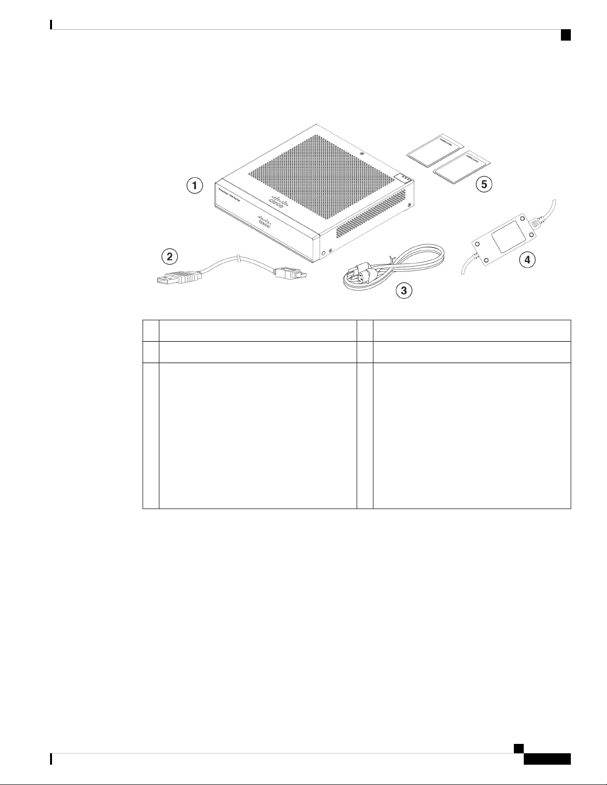
The following figure shows the package contents for the Firepower 1010. Note that the contents are subject
to change and your exact contents might contain additional or fewer items.
Cisco Firepower 1010 Hardware Installation Guide
4
Page 9
Overview
Serial Number Location
Figure 2: Firepower 1010 Package Contents
5
Useful Links Cisco Firepower 1010
The steps in the Useful Links document send you
to the documentation you need to install, set up,
and configure your 1010.
Start Here Cisco Firepower 1010 for Firepower
Threat Defense
This document tells how to cable and set up the
FTD using Firepower Device Manager (FDM) (a
simplified, single device manager included on the
device).
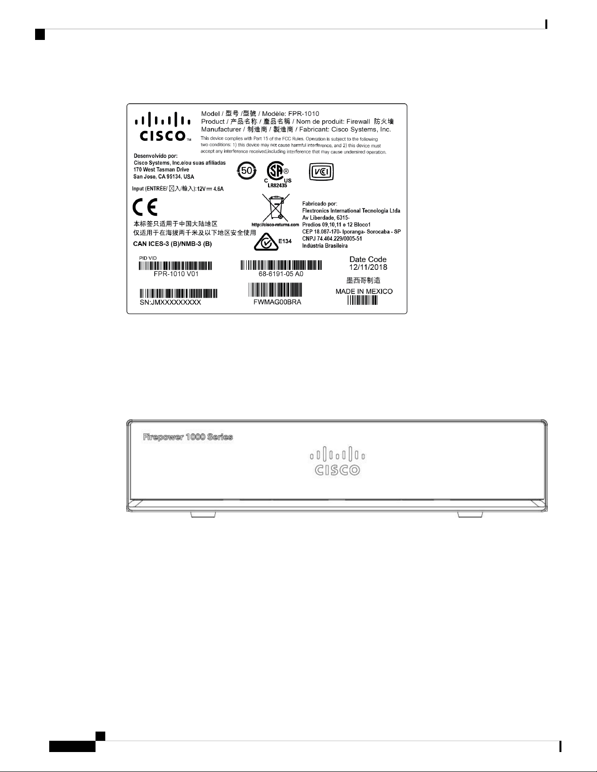
Serial Number Location
You can view the serial number and additional model information on the compliance label located on the
bottom of the chassis. The following figure shows a sample compliance label.
USB console cable (Type A to Type B)2Chassis1
Power supply4Power cord3
Cisco Firepower 1010 Hardware Installation Guide
5
Page 10
Front Panel
Overview
Figure 3: Compliance Label on the Firepower Chassis
Front Panel
Rear Panel
The following figure shows the front panel of the Firepower 1010. Note that there are no connectors or LEDs
on the front panel.
Figure 4: Firepower 1010 Front Panel
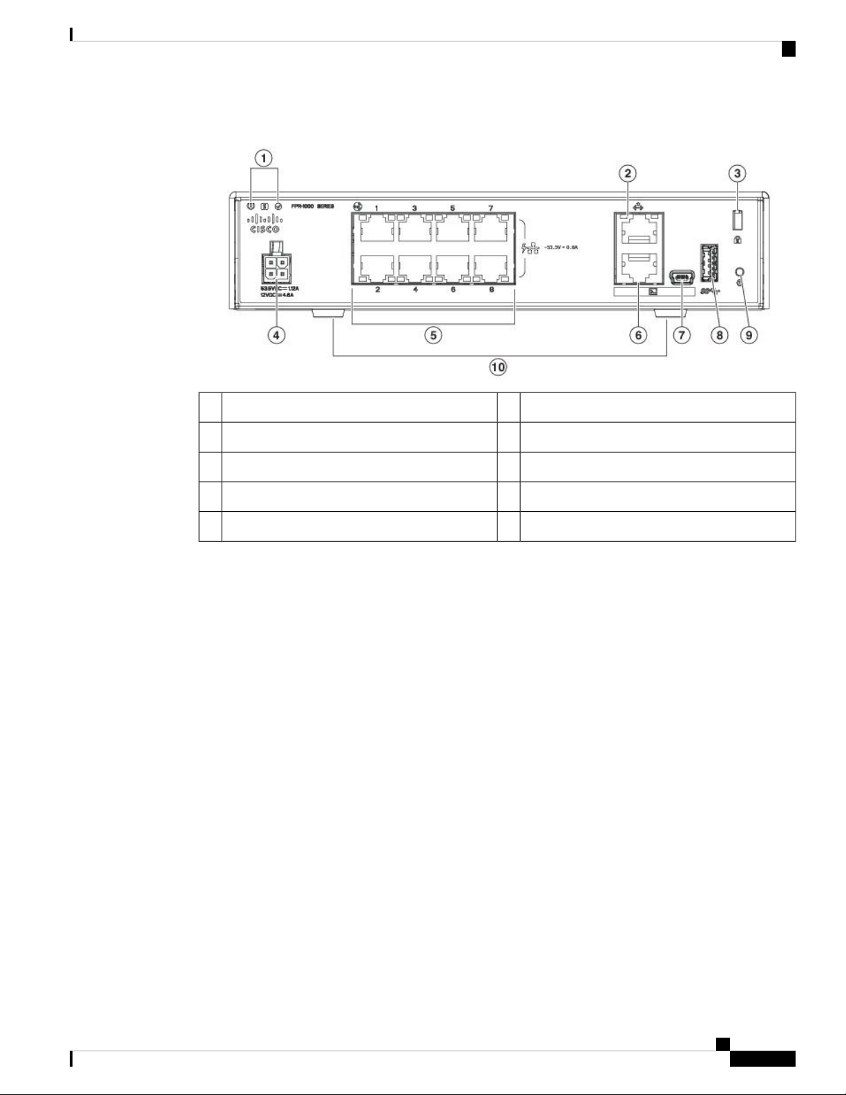
The following figure shows the rear panel of the Firepower 1010. See Status LEDs, on page 7 for a description
of the LEDs.
Cisco Firepower 1010 Hardware Installation Guide
6
Page 11
Overview
Status LEDs
Figure 5: Firepower 1010 Rear Panel
Management port2Status LEDs1
Status LEDs
Power cord socket4Lock slot3
Console port6Network data ports5
USB Type A port8USB Mini B port7
Rubber feet10Reset button9
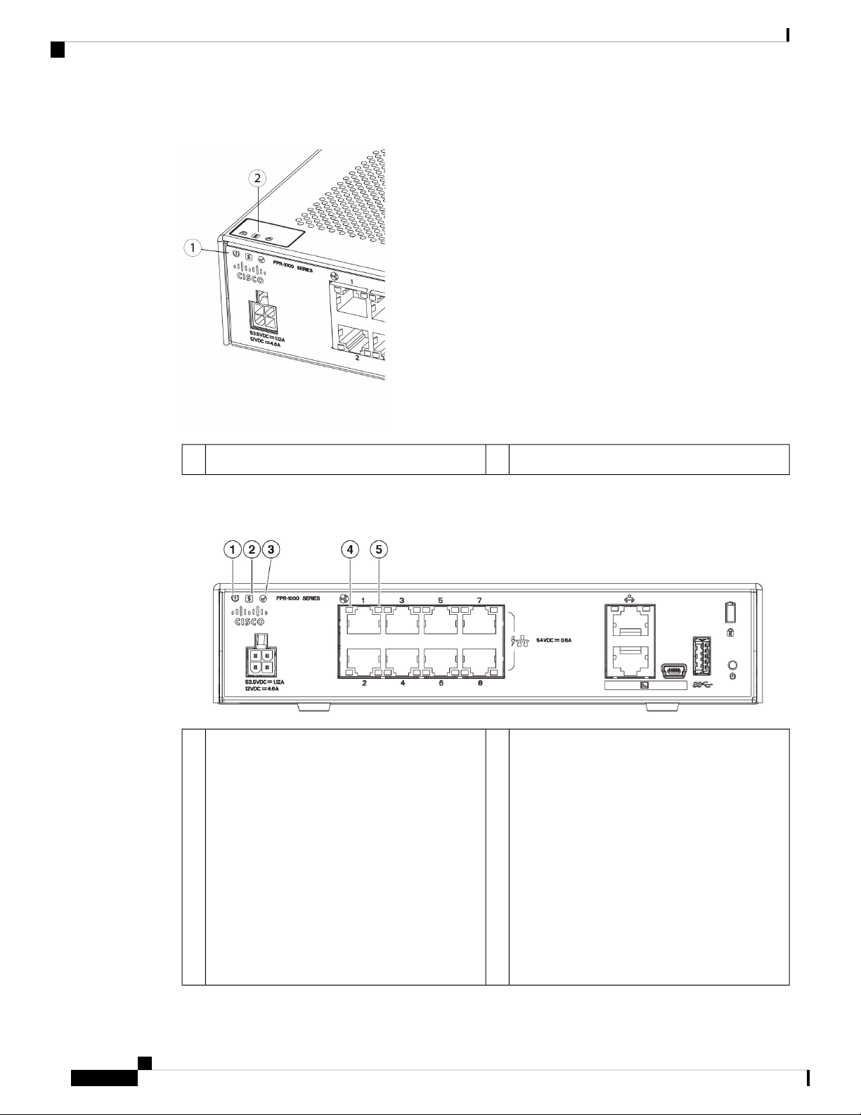
Facing the rear of the chassis, the LEDs are located on the top left edge (facing the front of the chassis, they
are in the back right corner of the top). The network port LEDs are at the top sides of each network port.
The following figure shows the status LEDs on the rear panel and on the cover of the chassis.
Cisco Firepower 1010 Hardware Installation Guide
7
Page 12
Status LEDs
Overview
Figure 6: Firepower 1010 Status LEDs
Power, Status, and Active LEDs on top of chassis2Power, Status, and Active LEDs on rear of chassis1
The following figure shows all of the LEDs on the rear panel and describes their states.
Figure 7: Firepower 1010 Rear Panel LEDs
Status
1
Power supply status:
• Off —Power supply off.
• Green—Power supply on.
2Power
System operating status:
• Green—Normal system function.
• Amber—Critical alarm indicating one or
more of the following:
• Major failure of a hardware or software
component.
• Over-temperature condition.
• Power voltage outside the tolerance
range.
Cisco Firepower 1010 Hardware Installation Guide
8
Page 13

Overview
Hardware Specifications
Network
3
4Active
Status of the failover pair:
• Off— Failover is not operational.
• Green—Failover pair operating normally.
The LED is green always unless the chassis
in a high availability pair.
• Amber—When the chassis is in a high
availability pair, the LED is amber for the
standby unit.
Network
5
Status of the network ports.
Connection-speed status (S):
• Green, flashing—One flash every three
seconds = 10 Mbps.
• Green, flashing—Two rapid flashes = 100
Mbps.
• Green, flashing—Three rapid flashes = 1000
Mbps.
Status of the network ports.
Link status (L):
• Off—No link, or port is not in use.
• Green—Link established.
• Green, flashing—Link activity.
Hardware Specifications
The following table contains hardware specifications for the Firepower 1010.
Table 2: Firepower 1010 Hardware Specifications
1.82 x 7.85 x 8.07 in. (4.62 x 19.94 x 20.50 cm)Dimensions (H x W x D)
3 lb (1.36 kg)Weight
System power
Temperature
30 W
Not including any PoE devices connected to the chassis. 55 W is the maximum
power for the power supply.
Note
Note
Operating: 32 to 104⁰F (0 to 40⁰C)
Derate the maximum operating temperature 1.5⁰ C per 1000 ft above sea level.
Nonoperating: -13 to 158°F (-25 to 70°C) maximum altitude is 40,000 ft
PoE+ is supported in a future software release.
Use the power supply (part number 341-100765-01) that shipped with
the chassis. It supports PoE+.
Cisco Firepower 1010 Hardware Installation Guide
9
Page 14

Product ID Numbers
Overview
Humidity
Altitude
Product ID Numbers
The following table lists the field-replaceable PIDs associated with the Firepower 1010. The spare components
are ones that you can order and replace yourself. If any internal components fail, you must RMA the entire
chassis. See the show inventory command in the Cisco Firepower Threat Defense Command Reference or
the Cisco ASA Series Command Reference to display a list of the PIDs for your Firepower 1010.
Table 3: Firepower 1010 PIDs
Operating: 90%
Nonoperating: 10 to 90%
Operating: 0 to 9843 (3000 m)
Nonoperating: 0 to 15,000 ft (4570 m)
0 dBaAcoustic noise
DescriptionPID
Cisco Firepower 1010 NGFW desktop applianceFPR1010-NGFW-K9
Cisco Firepower 1010 accessory kitFPR1K-DT-ACY-KIT
Power Cord Specifications
Each power supply has a separate power cord. Standard power cords or jumper power cords are available for
connection to the security appliance. The jumper power cords for use in racks are available as an optional
alternative to the standard power cords.
If you do not order the optional power cord with the system, you are responsible for selecting the appropriate
power cord for the product. Using a incompatible power cord with this product may result in electrical safety
hazard. Orders delivered to Argentina, Brazil, and Japan must have the appropriate power cord ordered with
the system.
Note
Only the approved power cords or jumper power cords provided with the chassis are supported.
The following power cords are supported.
Cisco Firepower 1010 115-W power supplyFPR1K-DT-PWR-AC
Cisco Firepower 1010 115-W power supply (spare)FPR1K-DT-PWR-AC=
Cisco Firepower 1010 rack-mount kit (spare)FPR1K-DT-RACK-MNT=
Cisco Firepower 1010 wall-mount kit (spare)FPR1K-DT-WALL-MNT=
Cisco Firepower 1010 Hardware Installation Guide
10
Page 15

Overview
Power Cord Specifications
Figure 8: Argentina (CAB-AC-C5-ARG)
Cord set rating: 2.5 A, 250 V2Plug: IRAM 20731
Connector: IEC 60320/C53
Figure 9: Australia (CAB-AC-C5-AUS)
Connector: IEC 60320/C53
Figure 10: Brazil (CAB-AC-C5-BRA)
Connector: IEC 60320/C53
Cord set rating: 2.5 A, 250 V2Plug: AUS 10S31
Cord set rating: 2.5 A, 250 V2Plug: NBR 141361
Cisco Firepower 1010 Hardware Installation Guide
11
Page 16

Power Cord Specifications
Figure 11: Canada (CAB-AC-C5)
Figure 12: China (CAB-AC-C5-CHI)
Overview
Cord set rating: 2.5 A, 125 V2Plug: NEMA 5-15P1
Connector: IEC 60320/C53
Connector: IEC 60320/C53
Figure 13: Europe (CAB-AC-C5-EUR)
Connector: IEC 60320/C53
Cord set rating: 2.5 A, 250 V2Plug: GB 2099.11
Cord set rating: 2.5 A, 250 V2Plug: CEE 7 VII1
Cisco Firepower 1010 Hardware Installation Guide
12
Page 17

Overview
Power Cord Specifications
Figure 14: India (CAB-AC-C5-IND)
Cord set rating: 2.5 A, 250 V2Plug: IS 12931
Connector: IEC 60320/C53
Figure 15: Italy (CAB-AC-C5-ITA)
Connector: IEC 60320/C53
Figure 16: Japan (CAB-AC-C5-JAP)
Connector: IEC 60320/C53
Cord set rating: 2.5 A, 250 V2Plug: CEI 23-06/VII1
Cord set rating: 3 A, 125 V2Plug: JIS C83031
Cisco Firepower 1010 Hardware Installation Guide
13
Page 18

Power Cord Specifications
Figure 17: Korea (CAB-AC-C5-KOR)
Figure 18: South Africa (CAB-AC-C5-SAF)
Overview
Cord set rating: 3.0 A, 250 V2Plug: KSC 832051
Connector: IEC 60320/C53
Connector: IEC 60320/C53
Figure 19: Switzerland (CAB-AC-C5-SWI)
Connector: IEC 60320/C53
Cord set rating: 2.5 A, 250 V2Plug: SABS 164-11
Cord set rating: 2.5 A, 250 V2Plug: SEV 10111
Cisco Firepower 1010 Hardware Installation Guide
14
Page 19

Overview
Power Cord Specifications
Figure 20: Taiwan (CAB-AC-C5-TWN)
Cord set rating: 2.5 A, 125 V2Plug: CNS 10917-21
Connector: IEC 60320/C53
Figure 21: United Kingdom (CAB-AC-C5-UK)
Cord set rating: 2.5 A, 250 V2Plug: BS1363A/SS1451
Connector: IEC 60320/C53
Cisco Firepower 1010 Hardware Installation Guide
15
Page 20

Power Cord Specifications
Overview
Cisco Firepower 1010 Hardware Installation Guide
16
Page 21

Installation Preparation
• Installation Warnings, on page 17
• Position the Chassis, on page 20
• Safety Recommendations, on page 20
• Maintain Safety with Electricity, on page 21
• Prevent ESD Damage, on page 21
• Site Environment, on page 22
• Site Considerations, on page 22
• Power Supply Considerations, on page 22
• Rack Configuration Considerations, on page 23
Installation Warnings
Be sure to read the Regulatory and Compliance Information document before installing the chassis.
Take note of the following warnings:
CHAPTER 2
Warning
Warning
Statement 1071—Warning Definition
IMPORTANT SAFETY INSTRUCTIONS
This warning symbol means danger. You are in a situation that could cause bodily injury. Before you work
on any equipment, be aware of the hazards involved with electrical circuitry and be familiar with standard
practices for preventing accidents. Use the statement number provided at the end of each warning to locate
its translation in the translated safety warnings that accompanied this device.
SAVE THESE INSTRUCTIONS
Statement 12—Power Supply Disconnection Warning
Before working on a chassis or working near power supplies, unplug the power cord on AC units; disconnect
the power at the circuit breaker on DC units.
Cisco Firepower 1010 Hardware Installation Guide
17
Page 22

Installation Warnings
Installation Preparation
Warning
Warning
Warning
Warning
Statement 19—TN Power Warning
The device is designed to work with TN power systems.
Statement 43—Jewelry Removal Warning
Before working on equipment that is connected to power lines, remove jewelry (including rings, necklaces,
and watches). Metal objects will heat up when connected to power and ground and can cause serious burns
or weld the metal object to the terminals.
Statement 94—Wrist Strap Warning
During this procedure, wear grounding wrist straps to avoid ESD damage to the card. Do not directly touch
the backplane with your hand or any metal tool, or you could shock yourself.
Statement 1004—Installation Instructions
Read the installation instructions before using, installing or connecting the system to the power source.
Warning
Warning
Warning
Statement 1005—Circuit Breaker
This product relies on the building's installation for short-circuit (overcurrent) protection. Ensure that the
protective device is rated not greater than: 20 A, 120 V, and 16 A, 250 V
Statement 1017—Restricted Area
This unit is intended for installation in restricted access areas. A restricted access area can be accessed by
skilled, instructed or qualified personnel.
Statement 1021—SELV Circuit
To avoid electric shock, do not connect safety extra-low voltage (SELV) circuits to telephone-network voltage
(TNV) circuits. LAN ports contain SELV circuits, and WAN ports contain TNV circuits. Some LAN and
WAN ports both use RJ-45 connectors. Use caution when connecting cables.
Cisco Firepower 1010 Hardware Installation Guide
18
Page 23

Installation Preparation
Installation Warnings
Warning
Warning
Warning
Warning
Statement 1024—Ground Conductor
This equipment must be grounded. To reduce the risk of electric shock, never defeat the ground conductor or
operate the equipment in the absence of a suitably installed ground conductor. Contact the appropriate electrical
inspection authority or an electrician if you are uncertain that suitable grounding is available.
Statement 1028—More Than One Power Supply
This unit might have more than one power supply connection. All connections must be removed to de-energize
the unit.
Statement 1029—Blank Faceplates and Cover Panels
Blank faceplates and cover panels serve three important functions: they prevent exposure to hazardous voltages
and currents inside the chassis; they contain electromagnetic interference (EMI) that might disrupt other
equipment; and they direct the flow of cooling air through the chassis. Do not operate the system unless all
cards, faceplates, front covers, and rear covers are in place.
Statement 1030—Equipment Installation
Warning
Warning
Warning
Only trained and qualified personnel should be allowed to install, replace, or service this equipment.
Statement 1040—Product Disposal
Ultimate disposal of this product should be handled according to all national laws and regulations.
Statement 1045—Short-Circuit Protection
This product requires short-circuit (overcurrent) protection to be provided as part of the building installation.
Install only in accordance with national and local wiring regulations.
Statement 1074—Comply with Local and National Electrical Codes
To reduce risk of electric shock or fire, installation of the equipment must comply with local and national
electrical codes.
Cisco Firepower 1010 Hardware Installation Guide
19
Page 24

Position the Chassis
Position the Chassis
See Desktop-Mount the Chassis, on page 26 for information on desktop-mounting the chassis.
Installation Preparation
Caution
Do not stack the chassis on top of another chassis. If you stack the units, they will overheat, which causes the
units to power cycle.
Whether positioning the chassis on a desktop, on a closet shelf, or mounting it on a wall, consider the following:
• Be sure to choose an area where the chassis is out of the way to make sure it is not bumped or accidentally
dislodged. The chassis has feet on the bottom so it does not sit flush where placed, thus allowing proper
air circulation through and around it. Make sure that the chassis is not tightly enclosed or crowded by
other objects that might impede proper circulation.
• Choose a location that lets you easily bring the power cord and Ethernet and console cables to the chassis,
with plenty of slack and yet tucked away, so they cannot be inadvertently unplugged.
Safety Recommendations
Observe these safety guidelines:
• Keep the area clear and dust free before, during, and after installation.
• Keep tools away from walkways, where you and others might trip over them.
• Do not wear loose clothing or jewelry, such as earrings, bracelets, or chains that could get caught in the
chassis.
• Wear safety glasses if you are working under any conditions that might be hazardous to your eyes.
• Do not perform any action that creates a potential hazard to people or makes the equipment unsafe.
• Never attempt to lift an object that is too heavy for one person.
Cisco Firepower 1010 Hardware Installation Guide
20
Page 25

Installation Preparation
Maintain Safety with Electricity
Maintain Safety with Electricity
Warning
Before working on a chassis, be sure the power cord is unplugged.
Be sure to read the Regulatory and Compliance Information document before installing the chassis.
Follow these guidelines when working on equipment powered by electricity:
• Before beginning procedures that require access to the interior of the chassis, locate the emergency
power-off switch for the room in which you are working. Then, if an electrical accident occurs, you can
act quickly to turn off the power.
• Do not work alone if potentially hazardous conditions exist anywhere in your work space.
• Never assume that power is disconnected; always check.
• Look carefully for possible hazards in your work area, such as moist floors, ungrounded power extension
cables, frayed power cords, and missing safety grounds.
• If an electrical accident occurs:
• Use caution; do not become a victim yourself.
• Disconnect power from the system.
• If possible, send another person to get medical aid. Otherwise, assess the condition of the victim,
and then call for help.
• Determine whether the person needs rescue breathing or external cardiac compressions; then take
appropriate action.
• Use the chassis within its marked electrical ratings and product usage instructions.
• The chassis is equipped with an AC-input power supply, which is shipped with a three-wire electrical
cord with a grounding-type plug that fits into a grounding-type power outlet only. Do not circumvent
this safety feature. Equipment grounding should comply with local and national electrical codes.
Prevent ESD Damage
ESD occurs when electronic components are improperly handled, and it can damage equipment and impair
electrical circuitry, which can result in intermittent or complete failure of your equipment.
Always follow ESD-prevention procedures when removing and replacing components. Ensure that the chassis
is electrically connected to an earth ground. Wear an ESD-preventive wrist strap, ensuring that it makes good
skin contact. Connect the grounding clip to an unpainted surface of the chassis frame to safely ground ESD
voltages. To properly guard against ESD damage and shocks, the wrist strap and cord must operate effectively.
If no wrist strap is available, ground yourself by touching the metal part of the chassis.
For safety, periodically check the resistance value of the antistatic strap, which should be between one and
10 megohms.
Cisco Firepower 1010 Hardware Installation Guide
21
Page 26

Site Environment
Site Environment
You can place the chassis on a desktop, on the wall, or in a rack. The location of the chassis and the layout
of the equipment rack or wiring room are extremely important for proper system operation. Placing equipment
too close together with inadequate ventilation and inaccessible panels can cause system malfunctions and
shutdowns. Improper placement can also make it difficult for you to access the chassis for maintenance.
Installation Preparation
Warning
Under no circumstances should you stack one chassis on top of one another. This disrupts cooling air flow to
the chassis and causes damage to the hardware.
See Hardware Specifications, on page 9 for information about physical specifications.
To avoid equipment failures and reduce the possibility of environmentally caused shutdowns, plan the site
layout and equipment locations carefully. If you are currently experiencing shutdowns or unusually high error
rates with your existing equipment, these considerations may help you isolate the cause of failures and prevent
future problems.
Site Considerations
Considering the following helps you plan an acceptable operating environment for the chassis, and avoid
environmentally-caused equipment failures.
• Electrical equipment generates heat. Ambient air temperature might not be adequate to cool equipment
to acceptable operating temperatures without adequate circulation. Make sure that the room in which
you operate your system has adequate air circulation.
• Ensure that the chassis cover is secure. The chassis is designed to allow cooling air to flow effectively
within it. An open chassis allows air leaks, which may interrupt and redirect the flow of cooling air from
the internal components.
• Always follow ESD-prevention procedures to avoid damage to equipment. Damage from static discharge
can cause immediate or intermittent equipment failure.
Power Supply Considerations
See Features, on page 1 and Hardware Specifications, on page 9 for more detailed information about the
power supply in the chassis.
When installing the chassis, consider the following:
• Check the power at the site before installing the chassis to ensure that it is free of spikes and noise. Install
a power conditioner, if necessary, to ensure proper voltages and power levels in the appliance-input
voltage.
• Install proper grounding for the site to avoid damage from lightning and power surges.
• The chassis does not have a user-selectable operating range. Refer to the label on the chassis for the
correct appliance input-power requirement.
Cisco Firepower 1010 Hardware Installation Guide
22
Page 27

Installation Preparation
• Several styles of AC-input power supply cords are available for the chassis; make sure that you have the
correct style for your site.
• Install an uninterruptible power source for your site, if possible.
Rack Configuration Considerations
See Rack-Mount the Chassis, on page 29 for the procedure for rack-mounting the chassis.
Consider the following when planning a rack configuration:
• If you are mounting a chassis in an open rack, make sure that the rack frame does not block the intake
or exhaust ports.
• Be sure enclosed racks have adequate ventilation. Make sure that the rack is not overly congested as each
chassis generates heat. An enclosed rack should have louvered sides and a fan to provide cooling air.
• In an enclosed rack with a ventilation fan in the top, heat generated by equipment near the bottom of the
rack can be drawn upward and into the intake ports of the equipment above it in the rack. Ensure that
you provide adequate ventilation for equipment at the bottom of the rack.
Rack Configuration Considerations
• Baffles can help to isolate exhaust air from intake air, which also helps to draw cooling air through the
chassis. The best placement of the baffles depends on the airflow patterns in the rack. Experiment with
different arrangements to position the baffles effectively.
Cisco Firepower 1010 Hardware Installation Guide
23
Page 28

Rack Configuration Considerations
Installation Preparation
Cisco Firepower 1010 Hardware Installation Guide
24
Page 29

Mount the Chassis
• Unpack and Inspect the Chassis, on page 25
• Desktop-Mount the Chassis, on page 26
• Wall-Mount the Chassis, on page 26
• Rack-Mount the Chassis, on page 29
Unpack and Inspect the Chassis
Note
The chassis is thoroughly inspected before shipment. If any damage occurred during transportation or any
items are missing, contact your customer service representative immediately. Keep the shipping container in
case you need to send the chassis back due to damage.
See Package Contents, on page 4 for a list of what shipped with the chassis.
CHAPTER 3
Step 1 Remove the chassis from its cardboard container and save all packaging material.
Step 2 Compare the shipment to the equipment list provided by your customer service representative. Verify that you have all
items.
Step 3 Check for damage and report any discrepancies or damage to your customer service representative. Have the following
information ready:
• Invoice number of shipper (see the packing slip)
• Model and serial number of the damaged unit
• Description of damage
• Effect of damage on the installation
Cisco Firepower 1010 Hardware Installation Guide
25
Page 30

Desktop-Mount the Chassis
Desktop-Mount the Chassis
You can mount the chassis on a desktop by placing it on a desk in a horizontal position. Make sure there are
no blockages or obstructions within one inch of the top of the chassis or within .5 inch of the sides and back,
so that nothing interferes with cooling. Do not remove the rubber feet included with the chassis. They are also
needed for proper cooling.
Figure 22: Desk Top Mount the Chassis
Mount the Chassis
Caution
Do not stack one chassis on top of another chassis. If you stack the units, they will overheat, which causes
the units to power cycle.
What to do next
Install the cables according to your default software configuration as described in the Getting Started Guide
for your software version.
Wall-Mount the Chassis
You can purchase an optional wall-mount kit (part number 69-100647-01). You can wall-mount the chassis
left-, right-, or rear panel-side up. You can use the wall-mount bracket to mark the holes for mounting it on
the wall. The wall-mount bracket is 7.682 x 6 inches. You need to make two level marks on the wall where
you want to hang the chassis. For vertical orientation (rear panel up), the holes should be 6.826 inches apart.
For side to side orientation, the holes should be 5.134 inches apart.
Follow these steps to mount your chassis on a wall.
Step 1 Choose an orientation (left-, right-, or rear panel-side up) and a location on the wall for the chassis.
Step 2 Use a pencil, ruler, and level to mark locations for the two mounting screws. You can use the wall-mount bracket itself
to mark either the top holes or the side holes.
Cisco Firepower 1010 Hardware Installation Guide
26
Page 31

Mount the Chassis
Figure 23: Wall-Mount Bracket
Wall-Mount the Chassis
Horizontal mounting2Vertical mounting1
Step 3 Attach the wall-mount bracket to the chassis using the three M3.0 x 6 mmL screws that came in the kit.
Cisco Firepower 1010 Hardware Installation Guide
27
Page 32

Wall-Mount the Chassis
Figure 24: Attach the Wall-Mount Bracket to the Chassis
Mount the Chassis
Step 4 Use the two Cisco-provided screws to drill into a stud, or use the anchors from the dry-wall kit to hang it into dry wall.
If you are mounting the chassis onto something other than drywall, such as wood or sheet metal, anchors may not be
required.
Step 5 Drill a hole into the wall at each mark that you made in Step 2.
These holes should be slightly smaller in diameter than anchors if you are using them. The recommended drill hole size
is 3/16 inches.
Step 6 Insert the anchors into the holes if needed, and be sure they are properly seated.
Step 7 Fasten each screw into its anchor until it protrudes about 1/4 inch.
Step 8 Pick up the chassis, align the screws in the anchors with the holes in the bottom of the wall-mount bracket, move the
chassis toward the wall until the screw heads are in the wall-mount bracket, and then slide it down until it rests on the
screws.
Caution
Do not mount the chassis with the rear panel facing downward. This orientation is not supported.
What to do next
Install the cables according to your default software configuration as described in the Getting Started Guide
for your software version.
Cisco Firepower 1010 Hardware Installation Guide
28
Page 33

Mount the Chassis
Rack-Mount the Chassis
Rack-Mount the Chassis
Step 1 Place the chassis with the top facing down on a large, stable work area. .
Step 2 Invert the sliding shelf and position it on the chassis. You can mount the chassis with the front or rear panel facing front.
Figure 25: Install the Rack-Mount Shelf on the Chassis
Step 3 Adjust the position of the chassis and the shelf until the three mounting holes in the dimples in the bottom of the shelf
are aligned with the mounting holes in the bottom of the chassis.
Step 4 Tighten the captive screws to lock the chassis into place on the rack-mount shelf.
Step 5 Carefully turn the rack-mount shelf right-side up.
Step 6 Install the power supply and bracket behind the chassis. Tighten the three screws on the bracket to secure it to the rack
shelf. You can tighten the thumb screw on the top of the bracket to secure the power supply. The bracket flexes when
the power supply is properly secured.
Caution
If you are using a torque screw driver or drill do not use more than 4 in-lbs.
Cisco Firepower 1010 Hardware Installation Guide
29
Page 34

Rack-Mount the Chassis
Figure 26: Install the Power Supply Bracket and Power Supply in the Rack-Mount Shelf
Mount the Chassis
Rack-mount shelf2Chassis1
Power supply4Power supply securing bracket3
Step 7 Slide the rack-mount shelf into the rack.
Figure 27: Slide Rack-Mount Shelf into Rack
Step 8 The chassis is now rack-mounted. Repeat Steps 1 through 7 to rack-mount a second chassis.
Cisco Firepower 1010 Hardware Installation Guide
30
Page 35

Mount the Chassis
Figure 28: Rack-Mounted Chassis
Rack-Mount the Chassis
What to do next
Install the cables according to your default software configuration as described in the Getting Started Guide
for your software version.
Cisco Firepower 1010 Hardware Installation Guide
31
Page 36

Rack-Mount the Chassis
Mount the Chassis
Cisco Firepower 1010 Hardware Installation Guide
32
Page 37

CHAPTER 4
Connect to the Console Port
• Connect to the Console Port with Microsoft Windows, on page 33
• Connect to the Console Port with Mac OS X, on page 35
• Connect to the Console Port with Linux, on page 35
Connect to the Console Port with Microsoft Windows
You must install a USB device driver the first time a Microsoft Windows-based PC is connected to the USB
console port on the chassis, otherwise the connection fails.
To uninstall the driver, use the Add Remove Programs utility or the Setup-exe program.
Note
Disconnect the console terminal before uninstalling the driver.
Step 1 Obtain the appropriate driver (Cisco_usbconsole_driver_X_X_zip, where X is a revision number) for your model from
the Cisco Download Software site, USB Console Software category.
Step 2 Install the driver.
Step 3 Connect a 5-pin USB Mini B to the console port as shown in the following figure.
Cisco Firepower 1010 Hardware Installation Guide
33
Page 38

Connect to the Console Port with Microsoft Windows
Figure 29: Firepower 1010 Console Port Connection
Connect to the Console Port
USB Mini B to USB Type A console cable2USB Mini B console port1
USB Type A3
Step 4 Connect the end of the cable with the DB-9 connector (or USB Type A) to the terminal or PC. If your terminal or PC has
a console port that does not accommodate a DB-9 connector, you must provide an appropriate adapter for that port.
The LED for the console port turns green and within a few moments the Found New Hardware Wizard appears.
Step 5 Follow the instructions to complete the driver installation.
Step 6 To communicate with the chassis, start a terminal emulator application. This software should be configured with the
following parameters:
• 9600 baud
• 8 data bits
• no parity
• 1 stop bit
• no flow control
Cisco Firepower 1010 Hardware Installation Guide
34
Page 39

Connect to the Console Port
Connect to the Console Port with Mac OS X
Connect to the Console Port with Mac OS X
Follow these steps to connect a Mac OS X system USB port to the console using the built-in OS X Terminal
utility, or alternatively you can use a separate terminal emulator application.
Step 1 Use the Finder to go to Applications > Utilities > Terminal.
Step 2 Connect the OS X USB port to the chassis.
Step 3 Enter the following commands to find the OS X USB port number:
Example:
macbook:user$ cd /dev
macbook:user$ ls -ltr /dev/*usb*
crw-rw-rw- 1 root wheel 9, 66 Apr 1 16:46 tty.usbmodem1a21
DT-macbook:dev user$
Step 4 Connect to the USB port with the following command followed by the chassis USB port speed:
Example:
macbook:user$ screen /dev/tty.usbmodem1a21 9600
Step 5 Enter Ctrl-a followed by d to disconnect the OS X USB console from the Terminal window.
Connect to the Console Port with Linux
Follow these steps to connect a Linux system USB port to the console using the built-in Linux Terminal utility.
Step 1 Open the Linux Terminal window.
Step 2 Connect the Linux USB port to the chassis.
Step 3 Enter the following commands to find the Linux USB port number:
Example:
root@usb-suse# cd /dev
root@usb-suse /dev# ls -ltr *ACM*
crw-r--r-- 1 root root 188, 0 Jan 14 18:02 ttyACM0
root@usb-suse /dev#
Step 4 Connect to the USB port with the following command followed by the chassis USB port speed
Example:
root@usb-suse /dev# screen /dev/ttyACM0 9600
Step 5 To disconnect the Linux USB console from the Terminal window, enter Ctrl-a followed by : then quit.
Cisco Firepower 1010 Hardware Installation Guide
35
Page 40

Connect to the Console Port with Linux
Connect to the Console Port
Cisco Firepower 1010 Hardware Installation Guide
36
 Loading...