

Page 1
CHAPTER
1
Overview
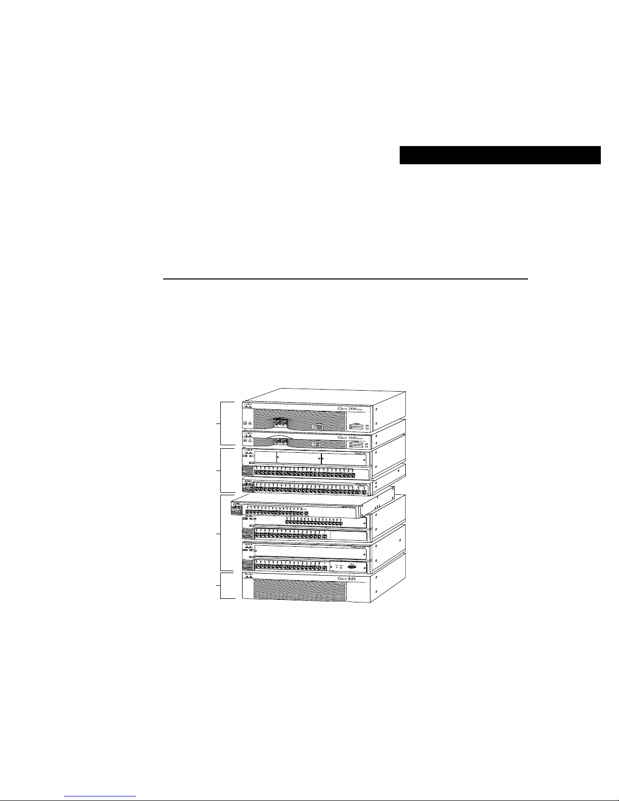
The FastHub 116T is an unmanaged 16-port 100BaseT Class II repeater for workgroups
and server farms. It is a member of an extended network system of stackable, modular LAN
and WAN products that increase LAN performance, connect remote of fices and users, and
provide secure access. Figure 1-1 shows the network system units.
Figure 1-1 FastHub 116T in an Extended Network System of Stackable LAN and
WAN Products
Routers
Switches
Hubs
Redundant
power system
1x
2x
3x
4x
5x
6x
7x
8x
9x
10x
11x
12x
13x
14x
15x
16x
16
H10259
Overview 1-1
Page 2

Feature Summary
Feature Summary
The FastHub has 16 fixed 100BaseTX ports (with an alternativ e uplink port for connecting
to other 100BaseTX hubs). Table 1-1 summarizes the FastHub features.
Table 1-1 Feature Summary
Feature Description
Compatibility • IEEE 802.3u Class II repeater compliant.
• Compatible with the 100BaseT standard for interoperability with
other 100BaseT products.
Performance 100-Mbps peak and aggregate throughput.
Redundancy Supports connection to the optional Cisco redundant power system
(RPS).
Front Panel Description
The front panel of the FastHub provides 16 100BaseTX ports, a 100BaseTX uplink port, a
set of LEDs, and a Mode button.
Ports
The ports on the front panel of the FastHub are all 100BaseTX ports with fixed RJ-45
connectors (see Figure 1-2). All ports are compatible with the 100BaseTX IEEE-802.3u
specification and can connect to any 100BaseTX device through standard Category 5
unshielded twisted-pair (UTP) cable.
1-2 FastHub 116T Installation Guide
Page 3
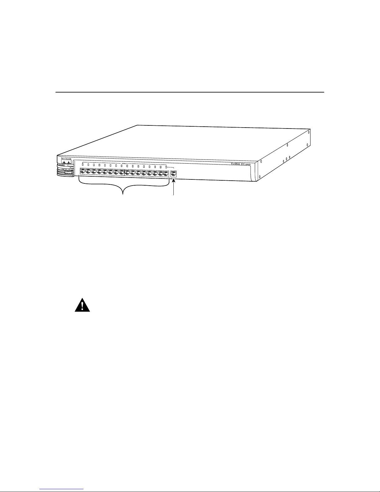
Figure 1-2 Front Panel Port Connectors
Front Panel Description
RPS
1x
2x
3x
4x
5x
6x
7x
8x
9x
10x
11x
12x
13x
14x
15x
16x
MODE
100BaseTX ports
16
100BaseTX
uplink port
Ports 1x through 16x have their transmit (TD) and receive (RD) pairs internally crossed.
Standard Category 5 UTP crossover cable is required when connecting these ports to
another hub, switch, or router (unless you are connecting to the uplink port on another
FastHub or 100BaseT hub).
Port 16, which is to the right of port 16x, is the 100BaseTX uplink port. This uplink port is
not internally crossed. Standard Category 5 UTP straight-through cable is required when
connecting this port to another FastHub 100BaseTX port or to the 100BaseTX port on
another hub, switch, or router.
H10260
Caution You will disable both ports if you connect to both the uplink port (port 16) and
port 16x.
For more information on connecting to these ports, see the “Connecting from the
100BaseTX Ports on the FastHub” section in the “Installing the FastHub” chapter.
Overview 1-3
Page 4

Front Panel Description
LEDs
You can use the FastHub LEDs to monitor network activity and performance. Figure 1-3
shows the location of the LEDs and the Mode button.
Figure 1-3 LEDs and Mode Button
power system
System status LED
Port mode LED
Redundant
LED
Mode
button
Port status LEDs
1x
Collision
LED
2x
3x
4x
H9261
H9909
RPS LED
The redundant power system LED shows the status of the RPS (see Table 1-2).
Table 1-2 RPS LED Description
Color RPS Status
Off Power OK (no RPS or RPS not powered up).
Solid green Power OK (RPS powered up and OK).
Solid amber Internal power supply not powered up, RPS connected but not OK.
Flashing green RPS and FastHub internal power supply are both powered up. Only one power
source can be supplying power to the FastHub.
If you are using the RPS, the FastHub power cord must not be plugged in. If
you are using the internal power supply, the RPS can be connected but must be
powered down.
1-4 FastHub 116T Installation Guide
Page 5

SYSTEM LED
COL LED
Front Panel Description
The system status LED shows whether the FastHub is powered up and provides an
indication of any problem with the main system board of the FastHub (see Table 1-3).
Note The system status LED and RPS LED are used together to isolate internal power
supply or RPS problems. See the “V erifying and T roubleshooting Y our Installation” section
in the “Installing the FastHub” chapter for detailed information.
Table 1-3 SYSTEM LED Description
Color System Status
Off FastHub powered down.
Solid green FastHub powered up and operational; no power problems.
Solid amber FastHub powered up but not operational; problem related to the main system
board of the FastHub (not internal power supply or RPS).
The group collision LED shows the frequency of collisions for all ports on the FastHub
(see Table 1-4). The LED flashes amber if one or more ports on the FastHub are involved
in a collision.
Note The flash rate of the group collision LED increases with an increase in collisions; a
high number of collisions causes the LED to appear solid amber.
Table 1-4 COL LED Description
Color System Status
Off No collisions
Flashing amber Collision
Solid amber High number of collisions
Overview 1-5
Page 6

Front Panel Description
Port Mode LED
The port mode LED indicates the ST AT (port status), UTL (bandwidth utilization), and ID
(unit identification) modes.
Note Port 16 (the uplink port) uses the port 16x LED.
STAT Mode
In port status mode, port LEDs show individual port status (see Table 1-5).
Table 1-5 Port Status LED Description
Color Port Status
Off No link (link down).
Green Link operational (with no activity).
Flashing green Link operational (with activity).
Rapidly alternating green/amber Faulty link
Alternating green/amber FastHub reset in progress.
1. This indication remains until the link fault is corrected. Possible causes are autopartition, jabber,
and isolated (carrier integrity error). Note that this state should not be confused with the “no link
status” (link down) indication where the link is not operational.
1
.
1-6 FastHub 116T Installation Guide
Page 7

Front Panel Description
UTL Mode
In utilization mode, bandwidth usage is shown for the FastHub. The port LEDs show the
current bandwidth and the peak bandwidth usage that occurred since the last reset.
The far-right solid green LED denotes the peak bandwidth that was recorded since the last
reset. All LEDs to the left of the solid green LED operate in a scalable pattern, flashing
green from left to right, to show the current bandwidth utilization. Table 1-6 lists the port
LEDs and the bandwidth associated with each LED.
Table 1-6 Utilization LED Scale
LED Mbps Activity
Port 1 0 to 6.25
Port 2 12.5
Port 3 18.75
Port 4 25
Port 5 31.25
Port 6 37.5
Port 7 43.75
Port 8 50
Port 9 56.25
Port 10 62.50
Port 11 58.75
Port 12 75
Port 13 81.25
Port 14 87.5
Port 15 93.75
Port 16 100
ID Mode
In unit identification mode, the LED for port 1 is solid green, indicating that the unit ID
number for the FastHub is 1. For the FastHub 116T, the unit ID number is always 1.
Overview 1-7
Page 8

Rear Panel Description
Mode Button
To change the mode being displayed by a port LED, press the Mode button to highlight in
sequence each of the modes: STAT, UTL, and ID. The Mode button is independent of the
Collision LED. When the desired mode is selected, release the button to make the change.
As long as you hold the Mode button down, the mode does not change. The selected mode
remains on for 30 seconds before returning to the default mode of STAT (port status).
Rear Panel Description
The rear panel of the FastHub provides an A C power receptacle and a redundant DC po wer
system (RPS) receptacle (see Figure 1-4). Only one power source can be supplying power
to the FastHub. Disconnecting power to the FastHub resets the FastHub itself.
If you want to use the internal power supply , which is an autoranging unit supporting input
voltages of 90 to 127/200 to 250 VAC, use the supplied AC power cord to connect the AC
power receptacle to an AC power outlet.
If you are using the RPS, the supplied AC po wer cord must not be plugged in. See the Cisco
RPS documentation for detailed information on connecting to the RPS.
Warning Use the Cisco RPS (model NFS0600-9632PE) only to power the external
device.
Figure 1-4 Rear Panel Connector
RATING
~
100-127/200-240V
0.5A/0.3A 50-60Hz
AC power
receptacle
1-8 FastHub 116T Installation Guide
Fan
CONSOLE PORT
For FastHub 200
and Catalyst only
DC INPUTS FOR REMOTE
POWER SUPPLY SPECIFIED
IN MANUAL.
+5V 6A +12V 1A
Redundant
power system
receptacle
AUI
For Catalyst only
H10261
Page 9

Examples of Using the FastHub
This section describes several possible network configurations using the FastHub.
Workgroups
You can create 100-Mbps workgroups by interconnecting FastHubs (FastHub 116T,
FastHub 216T, and FastHub 300 series), as shown in Figure 1-5.
Figure 1-5 FastHubs in a Workgroup Application
100BaseT-enabled
router or switch
Examples of Using the FastHub
FastHub 116T
FastHub
216T
Workgroup of up to
15 users/servers
FastHub 316T
Workgroup of up to 31 users/servers
Workgroup of up
to 14 users/servers
FastHub
300 series
stack
S6322
Overview 1-9
Page 10

Examples of Using the FastHub
Server Farms
Using the FastHub, you can create 100-Mbps server farms to increase centralized and
decentralized server performance, as shown in Figure 1-6.
Figure 1-6 FastHubs in a Server Farm Application
00BaseT-enabled
10-Mbps switch
10BaseT hub
100BaseT-enabled
router
10BaseT hub
FastHub 216T
Centralized
server farms
Server farm of
up to 15 servers
FastHub 116T
Server farm of up
to 15 servers
1-10 FastHub 116T Installation Guide
S6323
Page 11

Extended Network System
S6324
A system of routers, switches, and hubs can be combined to create a high-performance
network that extends beyond the main office LAN to connect to branch of fices, remote sites,
mobile users, and the Internet. Figure 1-7 is an application for an extended network system.
Figure 1-7 FastHub in an Extended Network Application
Main office
Internet
Examples of Using the FastHub
Cisco 1600 or
2500 series
Branch office
Catalyst 1900
series
100BaseT
server
FastHub
Catalyst 1900 series
116T
100BaseT hub-attached
workstations and servers
Catalyst 2820 or
Cisco 3600
series
Single workstations
Single workstations
Cisco 700 series CiscoRemote
Remote sites and mobile users
Overview 1-11
Page 12

Examples of Using the FastHub
1-12 FastHub 116T Installation Guide
 Loading...