

Page 1
Cisco Small Business Pro
ESW 500 Series Switches
ADMINISTRATION
GUIDE
Page 2

6bZg^XVh=ZVYfjVgiZgh
8^hXdHnhiZbh!>cX#
HVc?dhZ!86
6h^VEVX^[^X=ZVYfjVgiZgh
8^hXdHnhiZbhJH6EiZ#AiY#
H^c\VedgZ
:jgdeZ=ZVYfjVgiZgh
8^hXdHnhiZbh>ciZgcVi^dcVa7K
6bhiZgYVb!I]ZCZi]ZgaVcYh
8^hXd]VhbdgZi]Vc '%%d[[^XZhldgaYl^YZ#6YYgZhhZh! e]dcZcjbWZgh!VcY [VmcjbWZghVgZa^hiZYdc i]Z8^hXdLZWh^iZVilll#X^hXd#Xdb$\d$d[[^XZh#
889:!88:CI!8^hXd:dh!8^hXdAjb^c!8^hXdCZmjh!8^hXdHiVY^jbK^h^dc!8^hXdIZaZEgZhZcXZ!8^hXdLZW:m!i]Z8^hXdad\d!98:!VcYLZaXdbZidi]Z=jbVcCZildg`VgZigVYZbVg`h08]Vc\^c\i]ZLVnLZLdg` !
A^kZ!EaVn!VcYAZVgcVcY8^hXdHidgZVgZh Zgk^XZbVg`h0VcY6XX ZhhGZ\^higVg!6^gdcZi!6hncXDH!7g^c\^c\i]ZBZZi^c\IdNdj!8ViVanhi!8896!889E!88>:!88>E!88C6 !88CE!88HE!88KE!8^hXd!i]Z8^hXd8Zg i^[^ZY
>ciZgcZildg`:meZgiad\d!8^hXd>DH!8^hXdEgZhh!8^hXdHnhiZbh!8^hXdHnhiZbh8Ve^iVa!i]Z8^hXdHnhiZbhad\d!8^hX dJc^in!8daaVWdgVi^dcL^i]djiA^b^iVi^dc!:i]Zg;Vhi!:i]ZgHl^iX]!:kZci8ZciZg!;VhiHiZe!;daadlBZ
7gdlh^c\!;dgbH]VgZ!<^\V9g^kZ!=dbZA^c`!>ciZgcZiFjdi^Zci!>DH!^E]dcZ!^Fj^X`HijYn!>gdcEdgi!i]Z>gdcEdgiad\d!A^\]iHigZVb!A^c`hnh!BZY^VIdcZ!BZZi^c\EaVXZ!BZZi^c\EaVXZ8]^bZHdjcY!B<M!CZildg`Zgh!CZildg`^c\
6XVYZbn!CZildg`GZ \^higVg!E8Cdl!E>M!EdlZgEVcZah!Egd8dccZXi!HXg^eiH]VgZ!HZcYZg7VhZ!HB6GIcZi!HeZ Xigjb:meZgi!HiVX`L^hZ!I]Z;VhiZhiLVnid>cXgZVhZNdjg>ciZgcZiFjdi^Zci!IgVchEVi]!LZW:m!VcYi]ZLZW:m
ad\dVgZgZ\^hiZgZYigVYZbVg`hd[8^hXdHnhiZbh!>cX#VcY$dg^ihV[ [^a^ViZh^ci]ZJc^iZYHiViZhVcYXZgiV^cdi]ZgXdjcig^Zh#
6aadi]ZgigVYZbVg`hbZci^dcZY^ci]^hYdXjbZcidglZWh^iZVgZi]ZegdeZgind[i]Z^ggZheZ Xi^kZdlcZgh#I]ZjhZd[i]ZldgYeVgicZgYdZhcdi^beanVeVg icZgh]^egZaVi^dch]^eWZilZZc8^hXdVcYVcndi]ZgXdbeVcn#%-%.G
6bZg^XVh=ZVYfjVgiZgh
8^hXdHnhiZbh!>cX#
HVc?dhZ!86
6h^VEVX^[^X=ZVYfjVgiZgh
8^hXdHnhiZbhJH6EiZ#AiY#
H^c\VedgZ
:jgdeZ=ZVYfjVgiZgh
8^hXdHnhiZbh>ciZgcVi^dcVa7K
6bhiZgYVb!I]ZCZi]ZgaVcYh
© 2009 Cisco Systems, Inc. All rights reserved. OL-19128-01
Page 3

Contents
Chapter : Getting Started 12
Introduction 12
Typical Installation Methods 13
Default Configuration settings on the ESW 500 Series Switches 14
Physical Connectivity 14
Connecting to the Switch 17
Using the Default Static IP Address 17
Using a Dynamic IP Address Allocated to the Switch By DHCP 22
Using the Cisco Configuration Assistant (CCA) 24
Navigating The Cisco Switch Configuration Utility 29
Using the Management Buttons 29
Performing Common Configuration Tasks 30
Checking the Software Version 30
Checking the System Information 30
Viewing what Devices are Attached to the Switch 31
Configuring the VLAN Settings for the Switch 32
Configuring individual ports using Cisco Smartport Roles 33
Smartport Roles 34
Checking the Device Power Consumption 38
Saving the Configuration 40
Upgrading the Firmware on the Switch 41
Resetting the Device 46
Manual Reset 47
Logging Off the Device 47
Using The Switch Console Port 48
Selecting Menu Options and Actions 48
Chapter : Managing Device Information 52
Understanding the Dashboards 52
Ports 59
Health and Monitoring 59
Common Tasks 60
ESW 500 Series Switches Administration Guide 3
Page 4

Contents
Help 60
Defining System Information 60
Viewing Device Health 62
Resetting the Device 64
Managing Cisco Discovery Protocol 65
Defining the Bonjour Discovery Protocol 68
TCAM Utilization 70
Chapter : Managing Smart Ports 72
Configuring Smart Ports for Desktops 73
Configuring Smart Ports for IP Phones and Desktops 77
Configuring Smart Ports for Access Points 80
Configuring Smart Ports for Switches 82
Configuring Smart Ports for Routers 84
Configuring Smart ports for Guests 87
Configuring Smart ports for Servers 89
Configuring Smart ports for Printers 91
Configuring Smart ports for VS Camera 94
Configuring Smart Ports for Other 96
Chapter : Configuring System Time 99
Defining System Time 99
Defining SNTP Settings 103
Defining SNTP Authentication 105
Chapter : Configuring Device Security 108
Passwords Management 108
Modifying the Local User Settings 110
Defining Authentication 111
Defining Profiles 111
Modifying an Authentication Profile 114
ESW 500 Series Switches Administration Guide 4
Page 5

Contents
Mapping Authentication Profiles 115
Defining TACACS+ 117
Modifying TACACS+ Settings 120
Defining RADIUS 122
Modifying RADIUS Server Settings 126
Defining Access Methods 127
Defining Access Profiles 128
Defining Profile Rules 131
Modifying Profile Rules 135
Defining Traffic Control 137
Defining Storm Control 138
Modifying Storm Control 140
Defining Port Security 141
Modifying Port Security 145
Defining 802.1x 146
Defining 802.1X Properties 147
Defining Port Authentication 149
Modifying 8021X Security 152
Defining Authentication 155
Modifying Authentication Settings 157
Authenticated Hosts 158
Defining Access Control 160
Defining MAC Based ACL 160
Adding Rule to MAC Based ACL 164
Modifying MAC Based ACL 166
Defining IP Based ACL 168
Modifying IP Based ACL 174
Adding an IP Based Rule 177
Defining ACL Binding 179
Modifying ACL Binding 180
Defining DoS Prevention 181
DoS Global Settings 181
ESW 500 Series Switches Administration Guide 5
Page 6

Contents
Defining Martian Addresses 183
Defining DHCP Snooping 185
Defining DHCP Snooping Properties 186
Defining DHCP Snooping on VLANs 188
Defining Trusted Interfaces 189
Binding Addresses to the DHCP Snooping Database 191
Query By 192
Query Results 193
Defining IP Source Guard 195
Configuring IP Source Guard Properties 195
Defining IP Source Guard Interface Settings 197
Querying the IP Source Binding Database 199
TCAM Resources 200
Query By 201
Query Results 201
Defining Dynamic ARP Inspection 202
Defining ARP Inspection Properties 203
Defining ARP Inspection Trusted Interfaces 205
Defining ARP Inspection List 207
Static ARP Inspection Table 208
Adding a Binding List entry 209
Assigning ARP Inspection VLAN Settings 210
Enabled VLAN Table 211
Chapter : Configuring Ports 213
Port Settings 213
Modifying Port Settings 215
Chapter : Configuring VLANs 219
Defining VLAN Properties 220
Modifying VLANs 222
Defining VLAN Membership 223
Modifying VLAN Membership 224
ESW 500 Series Switches Administration Guide 6
Page 7

Contents
Assigning Ports to Multiple VLANs 226
Defining Interface Settings 229
Modifying VLAN Interface Settings 230
Defining GVRP Settings 232
Modifying GVRP Settings 234
Defining Protocol Groups 236
Modifying Protocol Groups 237
Defining a Protocol Port 238
Chapter : Configuring IP Information 241
IP Addressing 241
Defining DHCP Relay 243
Defining DHCP Relay Interfaces 245
Managing ARP 247
ARP Table 249
Modifying ARP Settings 250
Domain Name System 251
Defining DNS Servers 251
Default Parameters 252
DNS Server Details 253
Mapping DNS Hosts 253
Chapter : Defining Address Tables 256
Defining Static Addresses 256
Defining Dynamic Addresses 259
Query By Section 261
Chapter : Configuring Multicast Forwarding 262
IGMP Snooping 262
Modifying IGMP Snooping 264
Defining Multicast Group 266
ESW 500 Series Switches Administration Guide 7
Page 8

Contents
Modifying a Multicast Group 268
Defining Multicast Forwarding 269
Modifying Multicast Forwarding 271
Defining Unregistered Multicast Settings 272
Chapter : Configuring Spanning Tree 275
Defining STP Properties 275
Global Settings 276
Defining Spanning Tree Interface Settings 278
Modifying Interface Settings 282
Defining Rapid Spanning Tree 284
Modifying RTSP 287
Defining Multiple Spanning Tree 289
Defining MSTP Properties 290
Defining MSTP Instance to VLAN 291
Defining MSTP Instance Settings 293
Defining MSTP Interface Settings 294
Chapter : Configuring Quality of Service 301
Managing QoS Statistics 302
Policer Statistics 302
Add Aggregated Policer Statistics 304
Resetting Aggregate Policer Statistics Counters 307
Queues Statistics 307
Adding Queues Statistics 309
Resetting Queue Statistics Counters 309
Defining General Settings 310
Defining CoS 310
Modifying Interface Priorities 312
Defining QoS Queue 313
Mapping CoS to Queue 316
Mapping DSCP to Queue 318
ESW 500 Series Switches Administration Guide 8
Page 9

Contents
Configuring Bandwidth 319
Modifying Bandwidth Settings 320
Configuring VLAN Rate Limit 322
Modifying the VLAN Rate Limit 324
Defining Advanced QoS Mode 324
Configuring DSCP Mapping 325
Defining Class Mapping 327
Defining Aggregate Policer 329
Modifying QoS Aggregate Policer 331
Configuring Policy Table 332
Modifying the QoS Policy Profile 335
Defining Policy Binding 337
Modifying QoS Policy Binding Settings 339
Defining QoS Basic Mode 340
Rewriting DSCP Values 341
Chapter : Configuring SNMP 343
SNMP Versions 343
SNMP v1 and v2 343
SNMP v3 343
Configuring SNMP Security 344
Defining the SNMP Engine ID 344
Defining SNMP Views 346
Defining SNMP Users 348
Modifying SNMP Users 350
Define SNMP Groups 351
Modifying SNMP Group Profile Settings 354
Defining SNMP Communities 355
Modifying SNMP Community Settings 358
Defining Trap Management 359
Defining Trap Settings 359
Configuring Station Management 361
ESW 500 Series Switches Administration Guide 9
Page 10

Contents
Modifying SNMP Notifications 365
Defining SNMP Filter Settings 367
Managing Cisco Discovery Protocol 370
Chapter : Managing System Files 373
Software Upgrade 374
Save Configuration 375
Copy Configuration 377
Via TFTP 378
Via HTTP 379
Active Image 379
DHCP Auto Configuration 381
Chapter : Managing Power-over-Ethernet Devices 382
Defining PoE Settings 382
Chapter : Managing System Logs 386
Enabling System Logs 386
Viewing the Device Memory Logs 388
Clearing Message Logs 389
Viewing the System Flash Logs 390
Clearing Flash Logs 391
Remote Log Servers 391
Modifying Syslog Server Settings 394
Chapter : Viewing Statistics 397
Viewing Ethernet Statistics 397
Defining Interface Statistics 397
Resetting Interface Statistics Counters 399
Viewing Etherlike Statistics 399
Resetting Etherlike Statistics Counters 401
Viewing GVRP Statistics 401
ESW 500 Series Switches Administration Guide 10
Page 11

Contents
Resetting GVRP Statistics Counters 403
Viewing EAP Statistics 403
Managing RMON Statistics 405
Viewing RMON Statistics 406
Resetting RMON Statistics Counters 408
Configuring RMON History 408
Defining RMON History Control 408
Viewing the RMON History Table 411
Defining RMON Events Control 413
Modifying RMON Event Log Settings 415
Viewing the RMON Events Logs 416
Defining RMON Alarms 417
Modifying RMON Alarm Settings 421
Chapter : Aggregating Ports 424
Defining EtherChannel Management 425
Defining EtherChannel Settings 427
Modifying EtherChannel Settings 429
Configuring LACP 431
Chapter : Managing Device Diagnostics 434
Ethernet Port Testing 434
Performing GBIC Uplink Testing 437
Configure Span (Port Mirroring) 438
Monitoring CPU Utilization 440
ESW 500 Series Switches Administration Guide 11
Page 12

Getting Started
Introduction
Getting Started
Introduction
Thank you for choosing the Cisco Small Business Pro ESW 500 Series Swit ch. The
ESW 500 series is a family of Ethernet switches that addresses network
infrastructure and access needs of small business customers for voic e, data, PCs,
Servers, and video applications. They are simple to deploy and manage for use
with IP phones, Acce ss Points, IP cameras, and Network Attached Storage
servers as well as most any Ethernet device. The ESW 500 series includes seven
Fast Ethernet and GigE switches in both 24- and 48-port configurations with PoE
and non-PoE options. The ESW 500 series also includes two 8 port PoE switches
in Fast Ethernet and GigE models. The switch models covered in this guide are:
ESW 500 Series Switch Port Configuration
ESW 520-8P 8 Port 10/100 PoE
ESW 540-8P 8 Port 10/100/1000 PoE
ESW 520-24 24 Port 10/100
ESW 520-24P 24 Port 10/100 PoE
ESW 520-48 48 Port 10/100
ESW 520-48P 48 Port 10/100 PoE
ESW 540-24 24 Port 10/100/1000
ESW 540-24P 24 Port 10/100/1000 PoE
ESW-540-48 48 Port 10/100/1000
This section provides information about the different methods to connect to the
switch, as well as some examples of a typical installation. It also provides an
introduction to the user interface, and includes the following:
• Typical Installation Methods, page 13
• Connecting to the Switch, page 17
- Using the Default Static IP Address, page 17
- Using a Dynamic IP Address Allocated to the Switch By DHCP, page 22
- Using the Cisco Configuration Assistant (C CA), page 24
• Navigating The Cisco Switch Configuration Utility, page 2 9
ESW 500 Series Switches Administration Guide 12
Page 13
Getting Started
Typical Installation Methods
• Performing Common Configuration Tasks, page 30
• Using The Switch Console Port, page 48
Typical Installation Methods
The first step in any installation scenario is to connect to the switch and configure
basic connectivity to ensure it communicates with the rest of the network.
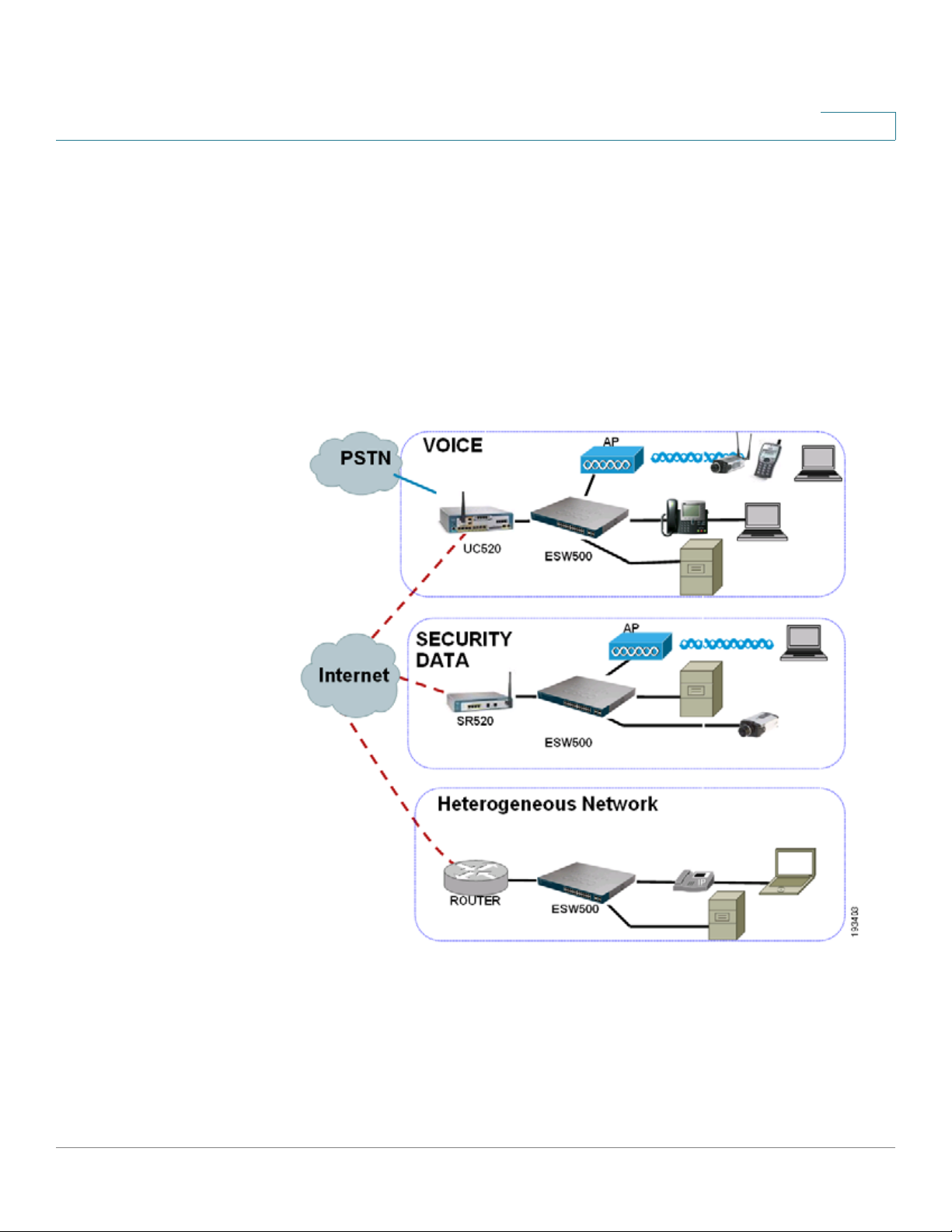
The following diagram illustrates three common installation scenarios:
In the first two scenarios, called VOICE and SECURITY DATA, you are adding an
ESW 500 switch to a new or existing Cisco Smart Business Communications
Systems (SBCS) network deployment. This deployment is either a VOICE network
with UC520 being the anchor device or SECURITY / DATA network with the
SR520 being the anchor device.
ESW 500 Series Switches Administration Guide 13
Page 14

Getting Started
Typical Installation Methods
In the third scenario, called Heterogeneous Network, you are adding an ESW 500
switch to a network which does not have any Cisco Small Business products.
Default Configuration settings on the ESW 500 Series Switche s
The ESW 500 series switches ship with a default configuration that enables
simplified installation and plug and play when connected into a Cisco Small
Business network such as SBCS. The default settings are as follows:
• Management VLAN is VLAN 1
• Management IP Address is obtained via DHCP by default. If the switch
times out on a Dynamic Host Configuration Protocol (DHCP) response, it
falls back to a static IP address 192.168.10.2 with subnet mask of
255.255.255.0.
• Voice VLAN is VLAN 100
• Cisco Discovery Protocol (CDP) is enabled on all ports
Physical Connectivity
Physical connections to the switch ar e described in the tables and graphics on the
next two pages.
Uplink Ports
ESW 500 Series Switch Copper SFP (mini-GBIC) Layer 2 Ethernet Ports
ESW 520-8P GE1 GE1 1-8
ESW 540-8P GE1 GE1 1-8
ESW 520-24/24P GE1-GE4 GE3-GE4 1-24
ESW 520-48/48P GE1-GE2 GE3-GE4 1-48
ESW 540-24/24P 11-12, 23-24 GE1-GE4 1-10, 13-22
ESW 540-48 23-24, 47-48 GE1-GE4 1-22, 25-46
NOTE On the 8 port devices, the Uplink and the GBIC port s can not be used at the same
time.
ESW 500 Series Switches Administration Guide 14
Page 15

Getting Started
Typical Installation Methods
The ESW 540-24/24P and ESW 540-48 use shared ports. When connecting to
uplink ports, the GE ports take precedence over the Copper ports. For example,
on an ESW 540-24, if you plug a device into GE1 , you cannot use port 11 . The other
port relationships are shown in the following table:
ESW 500 Series Switch GE Port Takes Precedence Over Copper Port
ESW 540-24/24P GE1 11
ESW 540-24/24P GE2 23
ESW 540-24/24P GE3 12
ESW 540-24/24P GE4 24
ESW 540-48 GE1 23
ESW 540-48 GE2 47
ESW 540-48 GE3 24
ESW 540-48 GE4 48
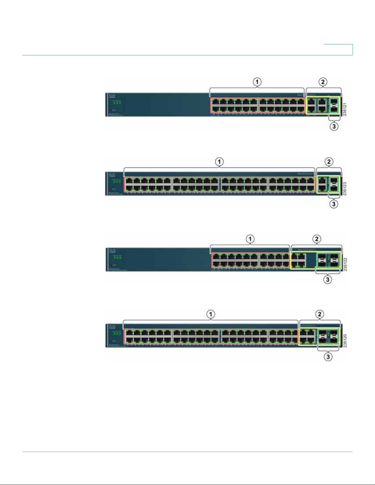
Compare the following table with the f our e x amples of switch fr ont panels that ar e
on the next page:
# Por t Description
1
2
3
Switch
Ports
Uplink
Ports
miniGBIC
Ports
The switch is equipped with auto-sensing, Ethernet (802.3) network ports
which use RJ-45 connectors. The Ethernet ports support network
speeds of 10 Mbps, 100 Mbps, or 1000 Mbps. They can operate in half
and full-duplex modes. Auto-sensing technology enables each por t to
automatically detect the speed of the device connected to it, and adjust
its speed and duplex accordingly. These ports are typically used for
devices such as PCs, s ervers, IP phones and Acc ess Points., and are
highlighted RED in the examples.
These ports are typically used for connecting to other switches, routers,
or network backbone devices, and are highlighted in YELLOW in the
examples. The mini-GBIC ports are a type of uplink port.
The mini-GBIC (Gigabit Interface Converter) port is a connection point for
a mini-GBIC expansion module, allowing the switch to be uplinked via
fiber to another switch. Each mini-GBIC port provides a link to a highspeed network segment or individual workstation at speeds of up to
1000 Mbps. The mini-GBIC ports are highlighted in GREEN in the
examples.
ESW 500 Series Switches Administration Guide 15
Page 16
Getting Started
Typical Installation Methods
ESW-520-24/24P
ESW-520-48/48P
ESW-540-24/24P
ESW-540-48
ESW 500 Series Switches Administration Guide 16
Page 17

Getting Started
Connecting to the Switch
Connecting to the Switch
This section contains information for starting the
provision the switch features. There are four different options to connect to the
switch, three of which launch the
Switch Configuration Utility.
Switch Configuration Utility
They are:
• Using the default static IP address of the switch
• Using Cisco Configuration As sistant
• Using a dynamic IP address allocated to the switch via DHCP (from DHCP
server)
• Using the Console
The first three options to connect to the switch will open the ESW 500 Series
Switch Configuration Utility, which is a web-based device manager used to
provision the switch. The console option uses a terminal emulation pro gram such
as HyperTerminal (bundled with Windows) or Putty (freeware).
NOTE Using the Console does not launch the Switch Configuration Utility and is
recommended for advanced users only. Using the Console is discussed at the end
of this chapter.
to
Using the Default Static IP Address
To start configuring the switch, follow these steps:
STEP1 Make sure that there are no devices connected to the switch, the switch is not
connected to the network, and then power up the switch by connecting the power
cord.
NOTE If the switch was previously connected to the network, it may have obtained
an IP address from a DHCP server . To perform a static IP addr ess installation,
disconnect all devices and remove the switch from the network. Then
perform a power cycle of the switch by unplugging the power cable, waiting
5 seconds, and plugging it back in.
STEP 2 Connect a PC to port 1 of the switch with an ethernet cable.
ESW 500 Series Switches Administration Guide 17
Page 18

Getting Started
Connecting to the Switch
STEP 3 If your PC is using a static IP address, make note of your current IP address
STEP4 Place the PC on the same subnet of the switch by configuring the PC with the
settings, and record them for future use.
following parameters:
• Static IP address — 192.168.10.11
• Subnet mask — 255.255.255.0
• Default gateway — 192.168.10.2
NOTE Details on how to change the IP address on your PC are dependent upon the
type of architecture and operating system installed. Use your PC’s local Help
and Support functionality and search for “IP Addressing”.
STEP 5 Open a web browser. Cisco recommends Internet Explorer version 6 or higher, or
Firefox version 3. Accept any requests to install Active-X plugin.
Enter http://192.168.10.2 in the address bar and press Enter. The
opens:
Log In
page
ESW 500 Series Switches Administration Guide 18
Page 19

Getting Started
Connecting to the Switch
Log In page
STEP 6 Enter a user name and password. The default user name is
cisco
password is
. Passwords are both case sensitive and alpha-numeric. Click
cisco
and the default
Log In.
STEP 7 While the system is verifying the login attempt, the Log In Progress Indicator
appears. The indicator dots rotate clockwise to indicate that the system is still
working. If the login attempt is successful, the Change Username/Password Page
opens.
NOTE After logging in using the default username and password you must change
to a new username and password. Only after the change has been made, can
you operate the device through the web browser. Every time you log in using
cisco as the username and password, you will be redirected to the Change
Username/Password Page.
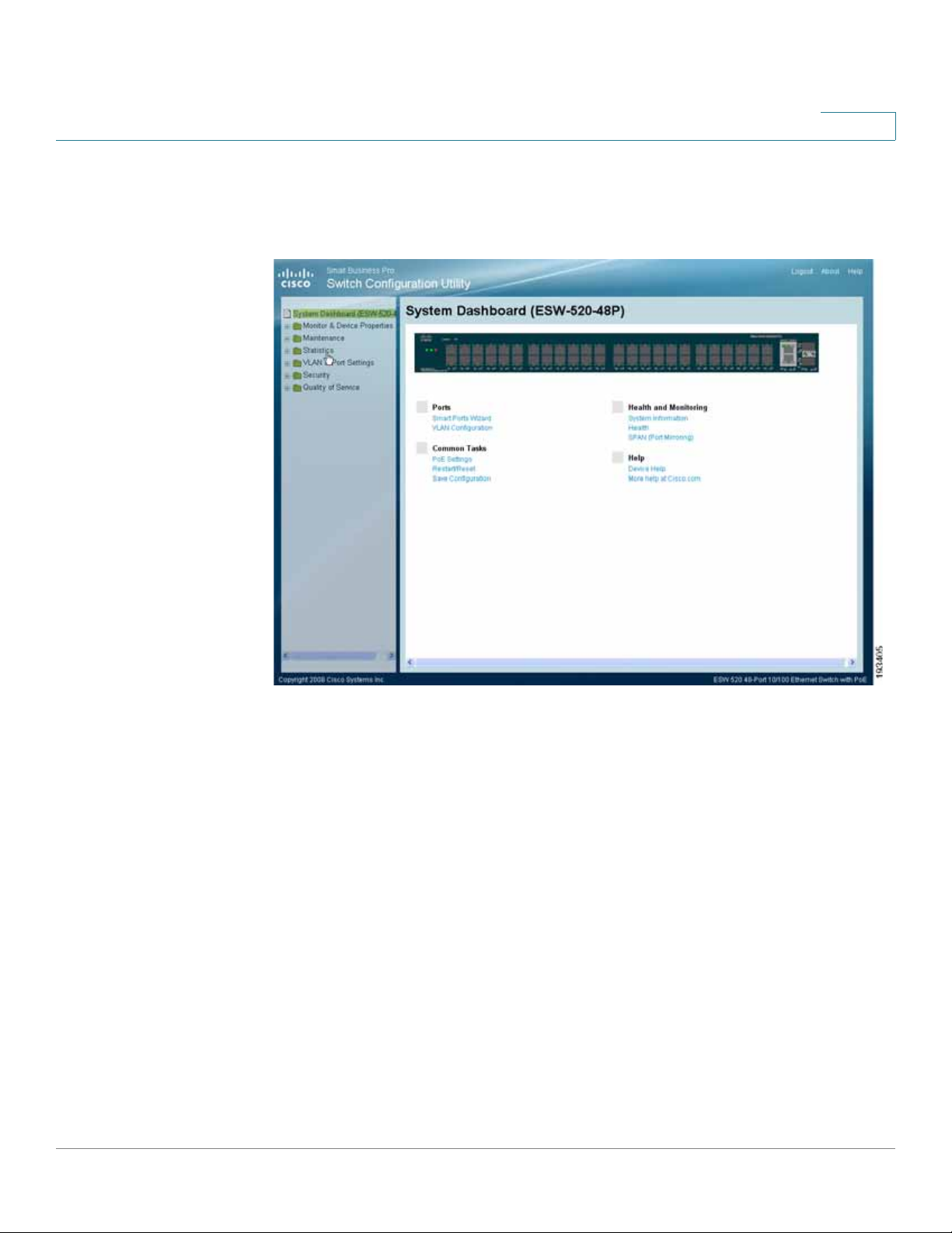
STEP 8 Click Apply. The
Switch Configuration Utility - System Dashboard
Page opens.
ESW 500 Series Switches Administration Guide 19
Page 20

Getting Started
Connecting to the Switch
Switch Configuration Utility - System Dashboard
STEP 9 Click Monitor & Device Properties > System Management > IP Addressing > IPv4
Interface
.
The
IPv4 Interface
page opens.
ESW 500 Series Switches Administration Guide 20
Page 21
Getting Started
Connecting to the Switch
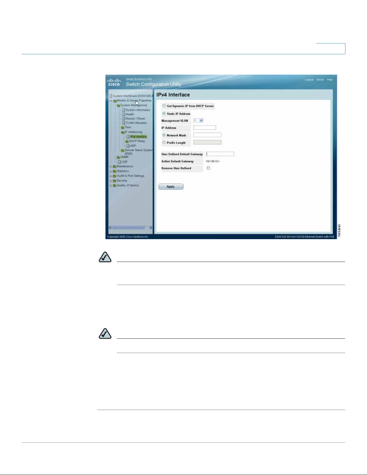
IPv4 Inter face Page
NOTE It is expected that the IP address to be assigned to the swit ch is known prior
to installation, based on the network topology.
STEP10 Select the Static IP address radio button and enter the IP Address, Network Mask
and User Defined Default Gateway. These must match the IP addressing subnet in
the network in which the ESW 500 switch will be deployed. Click Apply.
NOTE The PC loses the connection to the switch at this point.
STEP11 Now that you have finished using the PC to connect to the switch and made the
switch part of your network, you can reconfigure the PC to its original IP address
configuration and physical configuration as part of your network.
STEP12 You are now ready to proceed with additional switch configuration.
ESW 500 Series Switches Administration Guide 21
Page 22
Getting Started
Connecting to the Switch
NOTE If you will be using this PC for further switch configuration, it will need to be
on the same subnet as the switch.
Using a Dynamic IP Address Allocated to the Switch By DHCP
If this method of obtaining an IP address is used, you will need to have access to a
configuration device that would allow you to see what IP addresses the DHCP
server allocates. Prior to choosing this method of installation, speak with your
network administrator to ensure you will have the correct information available to
you.
NOTE By default, the IP address of the device is assigned dynamically.
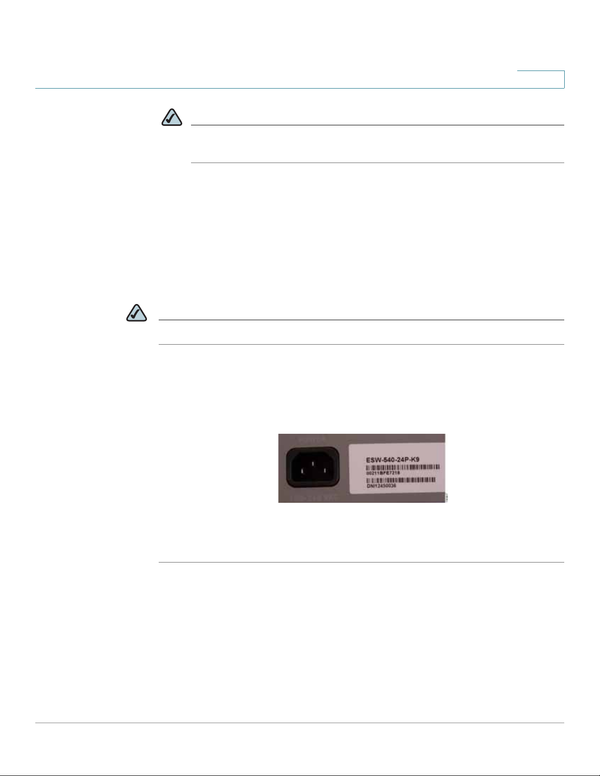
Log on to the DHCP server and check the IP address corresponding to the Media
Access C o ntrol (MAC) address of the switch. On the 24 and 48 port models, the
MAC address is on the back panel of the switch next to the power adapter. On the
8 port models, the MAC address is on the bottom of the device. The illustration
below shows a MAC address of 00211BFE7218.
Once you have the correct IP address that has been assigned to the switch, you
can begin configuring the switch.
STEP1 Open a web browser. Cisco recommends Internet Explorer version 6 or higher, or
Firefox version 3 or higher.
Enter the IP address that has been assigned to the switch in the address bar and
press Enter. The
Log In page
opens:
ESW 500 Series Switches Administration Guide 22
Page 23

Getting Started
Connecting to the Switch
Log In page
STEP 2 Enter a user name and password. The default user name is
password is
STEP 3 Click Log In. The
STEP4 A window opens that prompts you to change your username and password from
cisco
. Passwords are both case sensitive and alpha-numeric.
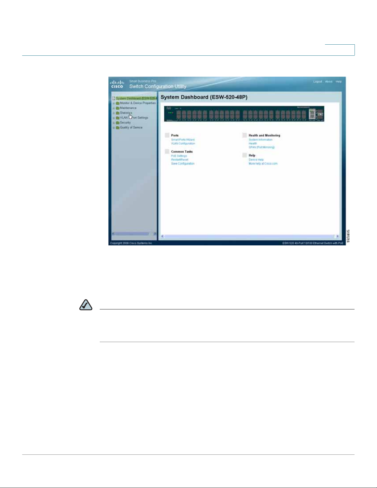
Switch Configuration Utility - System Dashboard
cisco
and the default
Page opens.
the default. Choose a new username and password, then click Apply .
ESW 500 Series Switches Administration Guide 23
Page 24
Getting Started
Connecting to the Switch
Switch Configuration Utility - System Dashboard
STEP 5 You are now ready to proceed with additional switch configuration.
Using the Cisco Configuration Assistant (CCA)
NOTE To perform an installation using CCA, you must have a PC with Windows Vista
Ultimate or Windows XP, Service Pack 1 or later installed and CCA version 2.2 or
higher installed.
The Cisco Configuration Assistant can be used to connect to and configure the
switch when there is an existing or new Smart Business Communications System
(SBCS) or with other Cisco Small Business Pro products such as the SA 500 Series
Security Appliance or the AP 541 Access Point. The ESW 500 series switch
obtains the management IP address via DHCP after it is connected to the network.
To begin installing the switch using CCA, perform the following steps:
ESW 500 Series Switches Administration Guide 24
Page 25
Getting Started
Connecting to the Switch
STEP1 Power on the ESW 500 series switch.
STEP 2 Connect one of the designated uplink ports on the ESW 500 series switch to the
STEP 3 Connect the PC with CCA installed to any access switch port on the ESW 500 or
expansion port on the UC520 or one of the switch ports on the SR520.
alternately, the UC500 or Small Business Pro router.
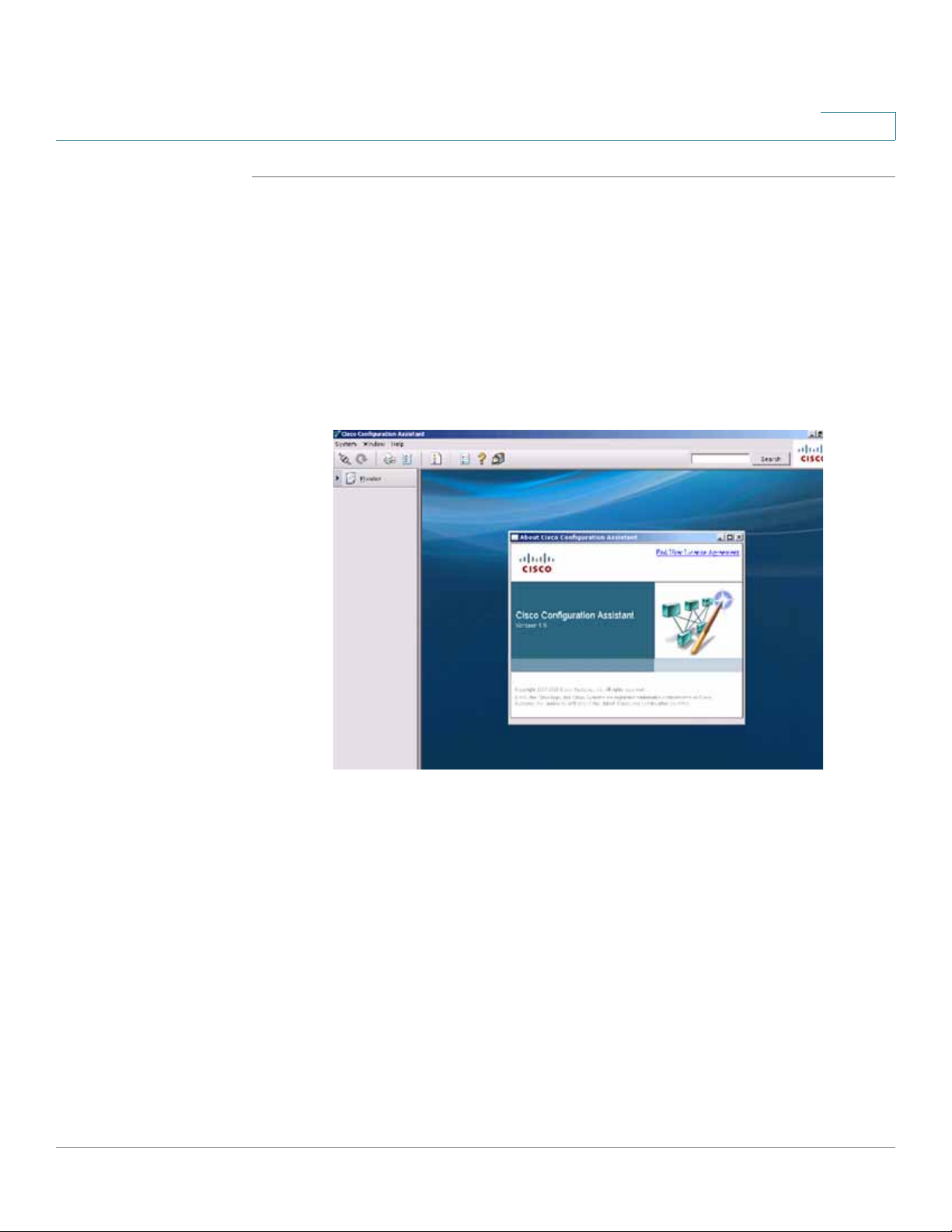
STEP4 Launch CCA. To verify you have CCA v ersion 2.2 or higher, click Help > About.
version page
opens.
The
CCA Version page
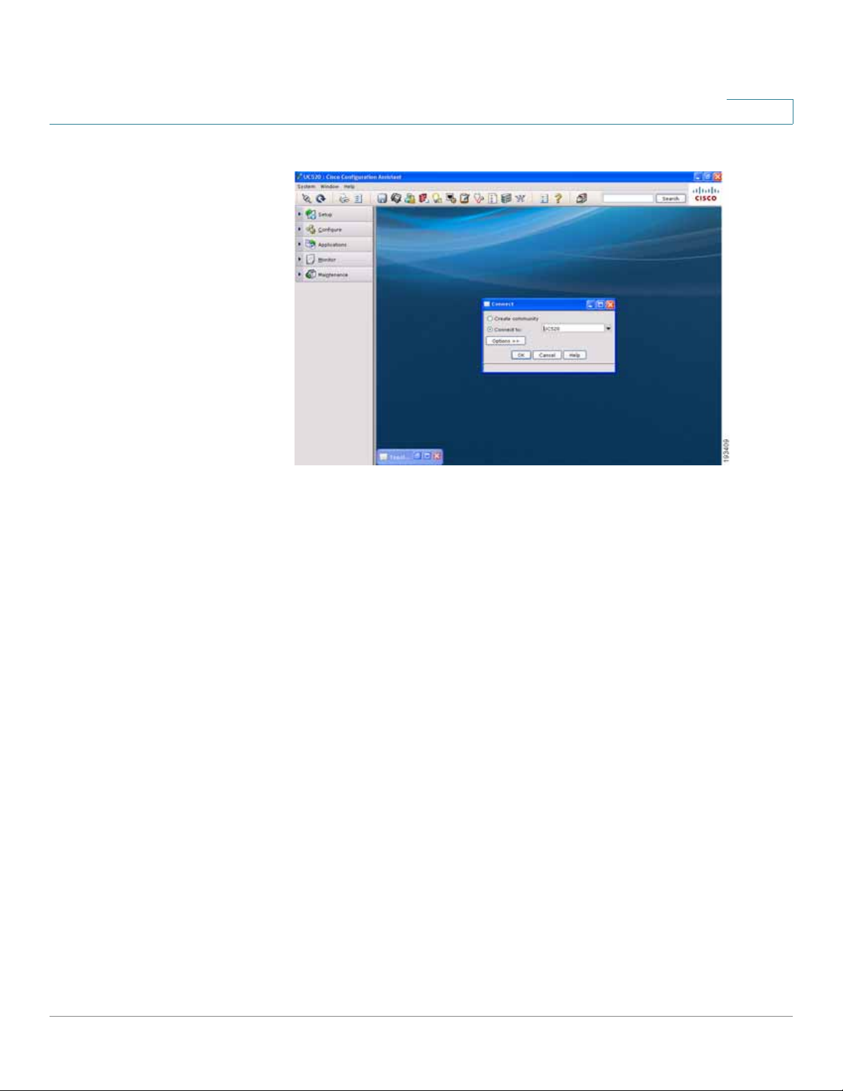
STEP 5 Connect to an existing community, or create a new one. For more information on
how to create a community, refer to the "How to create a CCA community" VOD at
https://www.myciscocommunity.com/docs/DOC1423#UC500_System_Level_Features
ESW 500 Series Switches Administration Guide 25
Page 26
Getting Started
Connecting to the Switch
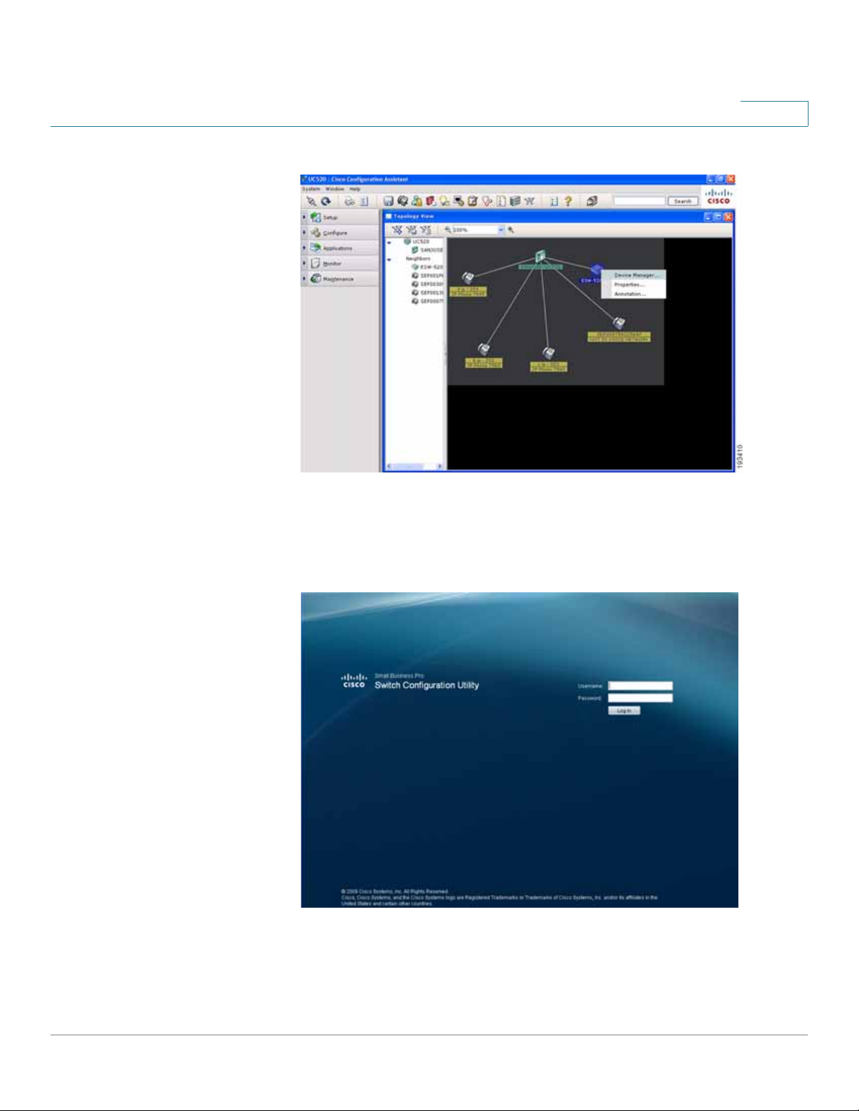
Connect page
STEP 6 Once you have connected to the community, the
displays the ESW 500 Series Switch. Right-click on the switch and it displays
three options:
• Device Manager
• Properties
• Annotation
You can now continue with configuring the switch by two different options; use
CCA to do all of the configuration, or use the Device Manager to go to the
switch Configuration Utility. Additional information is described in detail in the
appropriate CCA user documentation. This procedure uses the Device
Manager.
Topology View
opens and
ESW 500 Series Switches Administration Guide 26
Page 27
Getting Started
Connecting to the Switch
CCA Topology View page
STEP 7 Click on Device Manager.
The
Log In page
will launch in a new browser window.
Log In page
STEP 8 Enter a user name and password. The default user name is
cisco
password is
STEP 9 Click Log In. The
ESW 500 Series Switches Administration Guide 27
. Passwords are both case sensitive and alpha-numeric.
Switch Configuration Utility - System Dashboard
cisco
and the default
Page opens.
Page 28
Getting Started
Connecting to the Switch
STEP10 A window opens that prompts you to change your username and password from
the default. Choose a new username and password, then click Apply .
Switch Configuration Utility - System Dashboard
STEP11 You are now ready to proceed with additional switch configuration.
ESW 500 Series Switches Administration Guide 28
Page 29
Getting Started
Navigating The Cisco Switch Configuration Utility
Navigating The Cisco Switch Configuration Utility
The Cisco Switch Configuration Utility is a web-based device manager that is
used to provision the switch. You must have IP connectivity between the PC and
the switch to configure the switch. The following section describes how to
navigate within the interface.
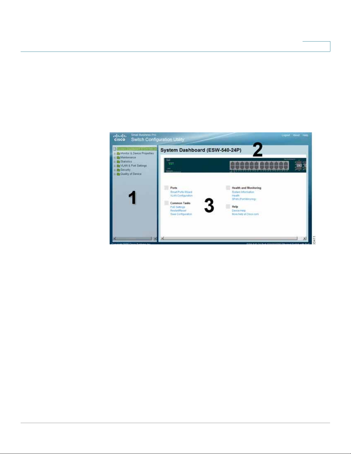
Switch Configuration Utility - System Dashboard Page
The following table lists the interface components with their corresponding
numbers:
Component Description
1 Navigation Pane The navigation pane provides easy navigation through the
configurable device features.The main branches expand
to provide the subfeatures.
2 Device View The device view contains a graphical representation of
the device faceplate, including the device status and port
LEDs. Clicking on a port will open up the Edit Port Page.
3 Getting Started
Links
Using the Management Buttons
Device Management buttons and icons provide an easy method of configuring
device information.
The getting started links allow you to navigate through the
different device features.
ESW 500 Series Switches Administration Guide 29
Page 30
Getting Started
Performing Common Configuration Tasks
Performing Common Configuration Tasks
Once the Switch Configuration Utility has been launched and you have logged into
the switch, these are some examples of the common configuration tasks you can
perform. Use the menus in the left navigation panel to choose a specific area of
configuration.
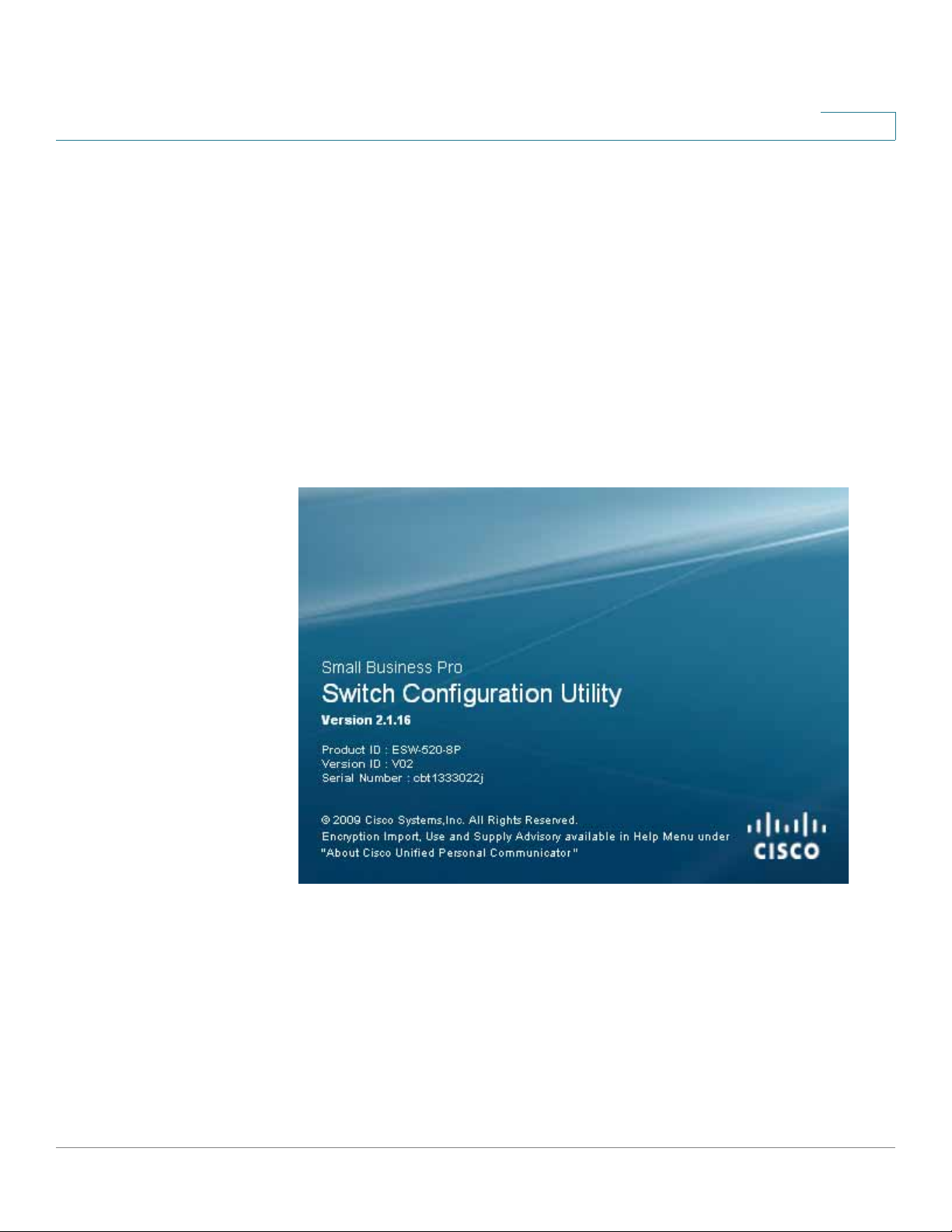
Checking the Software Version
To check the version of the software on the switch, click About at the top of the
page.
Software Version Page
Checking the System Information
Click on Monitor & Device Properties > System Management > System
Information. The
ESW 500 Series Switches Administration Guide 30
System Information
page opens.
Page 31

Getting Started
Performing Common Configuration Tasks
System Information Page
From this page you can configure the hostname of the switch, location and contact
information for support. Also, you can view important information such as the
system uptime, software version, MAC Address and Serial Number (SN).
Viewing what Devices are Attached to the Switch
To view what devices there are attached to the switch, click Monitor & Device
Properties > CDP. The
CDP page
opens.
ESW 500 Series Switches Administration Guide 31
Page 32

Getting Started
Performing Common Configuration Tasks
CDP Page
Review the ports for connecting IP Phones, PCs, Ac cess Points and the uplink to
the Cisco UC520 or SR520. You can change the Voice VLAN from the default of
100 if required.
Configuring the VLAN Settings for the Switch
To add or edit the default VLAN settings, click on VLAN & Port Settings > VLAN
Management > Properties. The
NOTE If the ESW 500 series switch is being deployed into a Cisco SBCS network,
Properties
the installation is plug and play. If the switch is being deployed into a nonCisco network, you will need to manually change VLAN settings.
page opens.
ESW 500 Series Switches Administration Guide 32
Page 33

Getting Started
Performing Common Configuration Tasks
Properties Page
Configuring individual ports using Cisco Smartport Roles
Smartpor t Role s make it easy to provision switch ports by automatically applying
the appropriate configuration fo r attached IP phones, access points, or other
devices to optimize network performance. The ESW 500 series switches support
the predefined roles listed below:
Role Description
Desktop
• Optimized for desktop connectivity
• Configurable VLAN setting
• Port security enabled to limit unauthorized access to the
network
IP Phone +
Desktop
• Optimized Quality of Service (QoS) for IP phone + desktop
configurations
• Voice traffic is placed on "Cisco-Voice" VLAN
• Configurable data VLAN
• QoS level assures voice-over-IP (VoIP) traffic takes precedence
• Port security enabled to limit unauthorized access to the
network
ESW 500 Series Switches Administration Guide 33
Page 34

Getting Started
Performing Common Configuration Tasks
Role Description
Router
Switch
Access Point
Guest
Server
Printer
VS Camera
Other
• Configured for optimal connection to a r outer or fir ewall f or WAN
connectivity
• Configured as an uplink port to another switch or router Layer 2
port for fast convergence
• Enables 802.1Q trunking
• Configured for optimal connection to a wireless access point
• Configurable VLAN
• Configured for a guest in a company, where the user would
need to be restricted to specific applications.
• Configured for optimal connection to a server
• Configured for optimal connection to a printer
• Configured for optimal connection to a Video Sur veillance
Camera
• An "Other" Smartports role allows for flexible connectivity of
non-specified devices
• Configurable VLAN
• No security
• No QoS policy
Smartport Roles
Default Smartport Roles applied to the individual ports for each type of device are
as follows:
Layer 2 Switch Ports Uplink Ports
ESW 500
Series
ESW 520-8P - 1-8 G1
ESW 540-8P - 1-8 G1
ESW 520-24 1-24 - G1-G4
ESW 520-24P - 1-24 G1-G4
ESW 520-48 1-48 - G1-G4
ESW 520-48P - 1-48 G1-G4
ESW 540-24 1-10, 13-22 - 11-12, 23-24
ESW 540-24P - 1-10, 13-22 11-12, 23-24
ESW 540-48 1-22, 25-46 - 23-24, 47-48
Desktop
Smartport Role
IP Phone +
Desktop
Smartport Role
Switch Smartport
Role
ESW 500 Series Switches Administration Guide 34
Page 35

Getting Started
Performing Common Configuration Tasks
NOTE The G in the port tables denotes 10/100/1000 (Gigabit) copper or GBIC ports on
the ESW520 series switches, and denotes the single G1 interface on the 8 port
versions of the switch.
The following st e ps show one e xample of using the Smart Ports Setting Wizard to
configure access points. It is not necessary to configure your switch in this manner .
STEP1 Click on the System Dashboard, and then on the Smartports Wizard. The
Ports Wizard
opens.
To change a port from the default setting to a different role, highlight the
appropriate port on this page by clicking on it, then select a different profile from
the drop-down list under Assign Profile:
Smart Ports Setting Wizard
STEP 2 Configure ports 4-6 for Access Points.
Smart
ESW 500 Series Switches Administration Guide 35
Page 36

Getting Started
Performing Common Configuration Tasks
Smart Ports Setting Wizard
STEP 3 Click Next. The
Access Point
window opens. To ensure all VLANs in the network
are trunked to the Wireless Access Points, select the drop-down list beside Trunk
Allowed VLANs. Select vlan 100 from the drop-down list to allow voice over
wireless.
Smart Ports Settings Wizard - Access Point
STEP4 Click Allow to ensure that VLAN100 shows up in the allowed list, and then click
Apply.
ESW 500 Series Switches Administration Guide 36
Page 37

Getting Started
Performing Common Configuration Tasks
Smart Ports Settings Wizard - Access Point
STEP 5 A confirmation page opens. Review your changes and click OK.
Smart Ports Settings Wizard - Access Point Setting Status
STEP 6 Return to the System Dashboard and click on the Smart Ports Wizard. The icons
for ports 4-6 should appear as follows:
ESW 500 Series Switches Administration Guide 37
Page 38

Getting Started
Performing Common Configuration Tasks
Smart Ports Setting
Checking the Device Power Consumption
Check the overview of the power consumption on the switch. Click System
Dashboard > PoE Settings. The
PoE Sett ings
page opens.
ESW 500 Series Switches Administration Guide 38
Page 39

Getting Started
Performing Common Configuration Tasks
PoE Settings Page
Click Edit to change a PoE setting.
The number of PoE devices supported on a switch depends on the power
requirements for each device and the switch model in question. To help illustrate
this, the PoE Device Support table shows the recommended number of POE
devices for 3 different scenarios:
Scenario 1 — Assumes the POE devices connected to the switch are all IEEE
802.3af Class 2 devices which draw less than 7.5W per device
Scenario 2 — Assumes the POE devices connected to the switch are a mix of IEEE
802.3af Class 2 & Class 3 devices devices which on average draw less than 11W
per device
Scenario 3 — Assumes the POE devices connected to the switch are all IEEE
802.3af Class 3 devices which draw less than 15.4W per device
ESW 500 Series Switches Administration Guide 39
Page 40

Getting Started
Performing Common Configuration Tasks
PoE Device Support
ESW 500
Series
Switch
ESW 520-8P 60 Watts Up to 15.4 Wa tts to each port up to the total budget
ESW 540-8P 120 Watts Up to 15.4 Wa tts to each port up to the total budget
ESW 520-24P 180 Watts 24 Devices 16 Devices 12 Devices
ESW 520-48P 380 Watts 48 Devices 32 Devices 24 Devices
ESW 540-24P 280 Watts 24 Devices 24 Devices 18 Devices
Total
Power
Scenario 1
PoE Devices
drawing < 7W
Scenario 2 PoE
Devices
drawing < 11W
Scenario 3 PoE
Devices drawing
< 15.4 W
In these scenarios, a device would be a wireless access point, IP phone, video
surveillance camera or other such device. Refer to the information that came with
your specific device for power consumption information.
Refer to additional sections in this guide for details on further PoE configuration.
Saving the Configuration
After any changes, always make sure to save the switch configuration. Click
Maintenance > File management > Save Configuration. The
page opens.
Save Configuration
ESW 500 Series Switches Administration Guide 40
Page 41

Getting Started
Performing Common Configuration Tasks
Save Configuration Page
Save Configuration
The
Source File Name — Indicates the device configuration file to copy and the
intended usage of the copied file (Running, Startup, or Backup).
Destination File Name — Indicates the device configuration file to copy to and the
intended usage of the file (Running, Startup, or Backup).
Define the relevant fields and then Click Apply. The Configuration Files are
updated.
Another option to quickly save the Running Configuration to the Startup
Configuration is to click Save Configuration at the top of the page. This link is
initially grayed out. Once switch configuration changes are made, the link
becomes active.
Page contains the fo llowing fields:
Upgrading the Firmware on the Switch
The following steps show how to download, install, and make a new firmware
release the active image on the switch.
ESW 500 Series Switches Administration Guide 41
Page 42

Getting Started
Performing Common Configuration Tasks
STEP1 Ensure the PC has IP connectivity to the ESW 500 series switch.
STEP 2 The switch can be upgraded through the TFTP or HTTP protocol. If you choose to
use TFTP, the PC ne eds to have a TFTP server running on it. A free TFTP server
can be downloaded from:
http://www.solarwinds.com/downloads/index.aspx
STEP 3 Download the latest ESW 500 series software file from:
www.cisco.com/go/esw500help
If you choose to use TFTP, make sure it is stored in the root director y of the TFTP
server running on your PC.
STEP4 Download the software image from the PC to the ES W 5 00 series switch. Click on
Maintenance > File Management > Software Upgrade. The
page opens.
Software Upgrade
Software Upgrade Page
STEP 5 For TFTP: Enter the PC IP address in the
the image in
Source File
field, then click Apply. The
TFTP Server
Software Upgrade
field, the exact filename for
page
shows the progress of the download.
ESW 500 Series Switches Administration Guide 42
Page 43

Getting Started
Performing Common Configuration Tasks
For HTTP: Click Browse and navigate to the file name of the image.
STEP 6 Once the download is complete, click on Maintenance > File Management > Active
Image The
Active Image Page
Active Image
page opens.
STEP 7 Choose the new image from the drop-down list under
STEP 8 Save the switch configuration. Click Maintenance > File Management > Save
Configuration. The Save Co
nfiguration
page opens.
After Reset
and click Apply.
ESW 500 Series Switches Administration Guide 43
Page 44

Getting Started
Performing Common Configuration Tasks
Save Configuration Page
STEP 9 Keep the defaults f or
STEP10 Reset the switch by clicking on Monitor & Device Properties > System
Source File Name
and
Destinat i o n File Name
and click Apply.
Management > Restart / Reset.
ESW 500 Series Switches Administration Guide 44
Page 45

Getting Started
Performing Common Configuration Tasks
Restar t / Reset Page
STEP11 Click on Reset / Reboot and the switch should reboot with the new image.
STEP12 After the switch has completed rebooting and is up and running, log back in.
STEP13 Ensure the software has been upgraded by clicking on About at the top of the
Dashboard page. A version page will appear:
ESW 500 Series Switches Administration Guide 45
Page 46

Getting Started
Performing Common Configuration Tasks
Resetting the Device
The Restart / Reset Page enables the device to be reset from a remote location.
Save all changes to the Running Configuration file before re setting the device by
clicking on Maintenance > File Management > Save Configuration. Define the
relevant fields and then click Apply. This prevents losing the current device
configuration.
To reset the device:
STEP1 Click Monitor & Device Properties > System Management > Restart / Reset. The
Restart / Reset Pa ge opens.
Restar t / Reset Page
STEP 2 Click one of the available Reset commands:
• Reset / Reboot — Resets the device. Ensure the device configuration has
been saved.
• Restore Default — Restores the device to the factory default configuration.
STEP 3 After the switch has completed rebooting and is up and running, relaunch the
Switch Configuration Utility and log back into the switch.
ESW 500 Series Switches Administration Guide 46
Page 47

Getting Started
Performing Common Configuration Tasks
NOTE If using CCA to launch the Switch Configuration Utility, right-click on switch
> Device Manager. Refresh the topology screen to get the latest IP address
for the switch.
Manual Reset
The Switch can be reset by inserting a pin or paper clip into the RESET opening.
Pressing the manual reset for 0 to 10 seconds reboots the switch. Pressing the
manual reset for longer than 10 seconds results in the switch being reset to
factory defaults.
Logging Off the Device
Click Logout at the top of the page. The system logs off. The
Utility
closes and the Log In page opens.
Switch Configuration
ESW 500 Series Switches Administration Guide 47
Page 48

Getting Started
Using The Switch Console Port
Using The Switch Console Port
The switch featur es a menu-based console interface for basic configuration of the
switch and management of your network. The switch can be configured using the
menu-based interface through the console port or through a telnet connection.
This section describes console interface configurat ion.
TIP Configuration of the switch through the Console Port requires advanced skills. This
should only be attempted by trained personnel.
Selecting Menu Options and Actions
Within the Console Interface, menus list options in numeric order. Actions appear
at the end of the page. To select menu options and actions, use the following keys
on your keyboard:
Key Function
Arrow keys Move the cursor up, down, left, or right.
Number key Press the menu number and then press Enter key to
select a menu option.
Tab Move the cursor from one field to the next on an editing
page.
Enter Select an option that is highlighted by the cursor.
Esc Return to the previous menu or page, or move cursor
from editable fields to
Use the following steps to connect to the switch using the console:
STEP1 Power up the ESW 500 Series switch.
Action
list.
STEP 2 Connect it to the network if required.
STEP 3 Use the console cable supplied with the switch to connect the serial port on the
PC to the console port on the switch.
ESW 500 Series Switches Administration Guide 48
Page 49

Getting Started
Using The Switch Console Port
STEP4 On the PC, launch a terminal emulation program such as HyperTerminal (bundled
with Windows) or Putty (freeware) and configure a new connection with the
following settings:
STEP 5 Save these settings and open a connection using the terminal emulation software.
If a blinking cursor appears, press Tab and enter the default username
press Tab again and enter the default password
• Speed or Bits Per Second — 115200
• Data Bits — 8
• Stop Bit — 1
• Parity — None
• Flow Control — None
• Serial Port — Choose the appropriate serial or COM port on the PC that the
console cable is connected to
cisco
and
cisco
. Press Enter to continue.
STEP 6 The switch main menu opens.
The System Configuration Menu line should be highlighted.
STEP 7 Press Enter. The page changes to System Configuration Menu.
ESW 500 Series Switches Administration Guide 49
Page 50

Getting Started
Using The Switch Console Port
STEP 8 Scroll down to option 6, IP Configuration, and press Enter. The IP Configuration
Menu opens.
STEP 9 Highlight option 1, IPv4 Address Configuration, and press Enter. The IPv4 Address
Configuration Menu opens.
STEP10 Highlight option 1, IPv4 Address Settings, and press Enter. The IPv4 Address
Settings page opens.
ESW 500 Series Switches Administration Guide 50
Page 51

Getting Started
Using The Switch Console Port
The current IP address setting for the ESW 500 series switch is shown. If the
switch is already connected to the network and obtained an IP address via DHCP,
this is the IP address which is used to launch the ESW 500 Switch Configuration
Utility.
If you need to change the IP address to a static IP address, perform the following
steps:
STEP1 Use the Right arrow key to highlight Edit, then press Enter. The IPv4 Address field
should be highlighted.
STEP 2 Using the arrow keys to navigate around the window, and the enter key to apply
changes, modif y the IPv4 Address, Subnet mask, and Default Gateway.
STEP 3 Change the DHCP Client field to be Disable by pressing the space bar.
STEP4 Press the ESC key, press the right arrow to highlight Save, and press Enter to save
all changes.
ESW 500 Series Switches Administration Guide 51
Page 52

Managing Device Information
Understanding the Dashboards
Managing Device Information
This section provides information for defining both basic and advanced system
information. This section contains the following topics:
• Understanding the Dashboards
• Defining System Information
• Viewing Device Health
• Managing Cisco Discovery Protocol
• Defining the Bonjour Discovery Protocol
• TCAM Utilization
Understanding the Dashboards
The
System Dashboard
configuring ports, viewing device health information, common device tasks, and
viewing online help.
• Ports — Includes Smartports Wizard and VLAN Configuration
• Health and Monitoring — Includes System Information, Health, and SPAN (Port
Mirroring)
• Common Tasks — Includes PoE Settings (PoE switches only), Restart / Re set,
and Save Configuration
• Help — Includes online Device Help and More help at Cisco.com
To open the
Click System Dashboard
device opens:
System Dashboard
page is the main window and contains links for
(Device Name)
Page:
. The System Dashboard page for your
ESW 500 Series Switches Administration Guide 52
Page 53

Managing Device Information
Understanding the Dashboards
System Dashboard (ESW-520-24) Page
ESW 500 Series Switches Administration Guide 53
Page 54

Managing Device Information
Understanding the Dashboards
System Dashboard (ESW-520-24P) Page
ESW 500 Series Switches Administration Guide 54
Page 55

Managing Device Information
Understanding the Dashboards
System Dashboard (ESW-520-48) Page
ESW 500 Series Switches Administration Guide 55
Page 56

Managing Device Information
Understanding the Dashboards
System Dashboard (ESW-520-48P) Page
ESW 500 Series Switches Administration Guide 56
Page 57

Managing Device Information
Understanding the Dashboards
System Dashboard (ESW-540-24) Page
ESW 500 Series Switches Administration Guide 57
Page 58

Managing Device Information
Understanding the Dashboards
System Dashboard (ESW-540-24P) Page
ESW 500 Series Switches Administration Guide 58
Page 59

Managing Device Information
Understanding the Dashboards
System Dashboard (ESW-540-48) Page
You can edit a specific port on the switch by clicking on that port from the device
view.
The
System Dashboard
graphical representation:
page contains the following port indicators in the device
• Green — Indicates the port is currently operating.
The
System Dashboard
pages contains the links to the following:
Ports
• Smart Ports Wizard — Opens the Smart Ports Wizard page.
• VLAN Co nfiguration — Opens the VLAN Properties Page.
Health and Monitoring
• System Information — Opens the System Information Page.
• Health — Opens the Health Page.
• SPAN (Port Mirroring) — Opens the SPAN (Port Mirroring) Page.
ESW 500 Series Switches Administration Guide 59
Page 60

Managing Device Information
Defining System Information
Common Tasks
• PoE Settings — Opens the PoE Settings Page (PoE switches only)
• Restart / Reset — Opens the Restart/Reset Page.
• Save Configuration — Opens the Save Configuration Page.
Help
• Device Help — Opens the online help.
• More help at Cisco.com — Provides a link to online Technical Support.
Defining System Information
The
System Information Page
information.To open the
contains parameters for configuring general device
System Information Page
:
ESW 500 Series Switches Administration Guide 60
Page 61

Managing Device Information
Defining System Information
STEP1 Click Monitor & Device Properties > System Management > System Information.
The
System Information Page
System Information Page
opens:
System Information Page
The
contains the following fields:
• System Name — Displays the user configured name of the system.
• System L ocation — Defines the location where the system is curr ently running.
The field range is from 0-160 characters.
• System Contact — Defines the name of the contact person. The field range is
0-160 characters.
• Login Banner — Defines a user-configurable message of up to 1000 characters
• System Object ID — Displays the vendor’s authoritative identification of the
network management subsystem contained in the entity.
• System Up Time — Displays the amount of time that has elapsed since the last
device reset. The system time is displayed in the following f ormat: Days, Hours,
ESW 500 Series Switches Administration Guide 61
Page 62

Managing Device Information
Viewing Device Health
Minutes and Seconds. For example: 41 days, 2 hours, 22 minutes and 15
seconds.
• Base MAC Address — Displays the device MAC address.
• Software Version — Displays the software version number.
• Boot Version — Indicates the system boot version currently running on the
device.
• Jumbo Frame — Indicates if Jumbo Frames are enabled . Jumbo Frames
become active after resetting the device. (Jumbo Frames are not available on
ESW-520 devices). The possible field values are:
• Unique Device Identifier — Displays the Unique Device Identifier (UDI). The
UDI provides a unique indentifier for Cisco devices. The device comes with the
UDI preconfigured. The UDI is composed of three parts, including:
-
-
Enable
Disable
— Enables Jumbo Frames on the device.
— Disables Jumbo Frames on the device.
- PID — The Product Identifier (PID) is an alphanumeric identifier that
identifies the specific Cisco hardware.
- VID —The Version Identifier (VID) provides tracking for the Customer-
Orderable PID version. The VD indicate s the number reportable
customer versions.
- SN — The Serial Number (SN) is unique to device, and identifies the
device and the Field Replaceable Unit (FRU).
STEP 2 Define the relevant fields.
STEP 3 Click Apply. The system information is defined, and the device is updated.
Viewing Device Health
The
Health Page
the device’s power and ventilation sources.
displays physical device inf ormatio n, including information about
ESW 500 Series Switches Administration Guide 62
Page 63

Managing Device Information
Viewing Device Health
STEP1 Click Monitor & Device Properties > System Management > Health. The
Page
opens:
Health Page
Health
Health Page
The
contains the following fields:
• Power Supply Status — Displays the power supply status. Power supply 1 is
displayed as PS in the interface, while the redundant power supply is
displayed as RPS. The possible field values are:
-
OK —
Indicates the power supply is operating normally.
-
Fail —
-
Not Present —
Indicates the power supply is not operating normally.
Indicates a redundant power supply is not connected.
• Fan Status — Displays the fan status. The device has five fans. Each fan is
denoted as fan plus the fan number. The possible field values are:
-
OK —
Indicates the fan is operating normally.
-
Fail —
ESW 500 Series Switches Administration Guide 63
Indicates the fan is not operating normally.
Page 64

Managing Device Information
Resetting the Device
-
Not Present
Resetting the Device
The
Restart / Reset
Save all changes to the Running Configuration file before r esetting the device. This
prevents the current device configuration from being lost.To open the
Reset Page
STEP1 Click Monitor & Device Properties > System Management > Restart / Reset. The
Restart / Reset Page
Restar t / Reset Page
-- Indicates the fan is not present.
page enables the device to be reset from a remote location.
Restart /
:
opens:
The following resets the device:
• Reset / Reboot — Resets th e de vice . En su re th e dev ice confi gu rat ion has been
saved.
• Restore Default — The device is restored to the factory default configuration.
ESW 500 Series Switches Administration Guide 64
Page 65

Managing Device Information
Managing Cisco Discovery Protocol
Managing Cisco Discovery Protocol
The Cisco Discover y Protocol (CDP) is a Cisco proprietary protocol that enables
devices to advertise their existence t o other de vices by CDP sending out periodic
updates to a Multicast address. In addition, CDP allows devices to receive
information about other devices on the same LAN or on the remote WAN side. The
system supports CDP versions 1 and 2. To enable CDP on the device:
STEP1 Click Monitor & Device Properties > CDP. The
CDP Page
CDP Page
opens:
CDP Page
The
The following fields are configurable by the user:
contains the following fields:
• CDP Status — Indicates if CDP is enabled on the device. The possible field
values are:
-
Enable
-
Disable
ESW 500 Series Switches Administration Guide 65
— Enables CDP on the device. This is the default value.
— Disables CDP on the device.
Page 66

Managing Device Information
Managing Cisco Discovery Protocol
• Voice VLAN — The Voice VLAN field displays the current Voice VLAN used by
the switch. The default is VLAN #100. This VLAN carries the voice traffic, and is
also advertised through the CDP to the other elements in the network. The user
can change the Voice VLAN via this screen.
The following fields display Neighbors Information and are Read-only.
• Device ID — Indicates the device ID that is advertised by neighboring devices.
• Local Interface — Indicates the receiving port number.
• Advertise Version — Indicates the CDP version advertised by the neighboring
device.
• Time to Live — Indicates the amount of time in seconds before the neighboring
device CDP information is aged out. The field default is 180 seconds.
• Capabilities — Indicat es the device capabilities advertised by the neighboring
devices. There are 11 capabilities whereby each capability is represented by a
one letter code. A neighbor device can advertise more than one capability,
which is presented as a series of one letter codes, for example: S I D represents Switch + Remotely-Managed-Device. The list of capabilities
follows:
-
R
— Router
-
T
— Trans Bridge
-
B
— Source Route Bridge
-
S
— Switch
-
H
— Host
-
I
— IGMP
-
r
— Repeater
-
P
— VoIP-Phone
-
D
— Remotely-Managed-Device
-
C
— CVTA
-
M
— Two-port Mac Relay
• Platform — Indicates product name and model number of the neighboring
device.
ESW 500 Series Switches Administration Guide 66
Page 67

Managing Device Information
Managing Cisco Discovery Protocol
• Port ID — Indicates the neighboring device’s port from which the CDP packet
was sent.
STEP 2 Select Enable in the
the device.
STEP 3 Define a VLAN ID to be advertised by the device in the
STEP4 Click Apply. CDP is enabled, and the device is updated.
To view additional neighboring device CDP information:
STEP1 Click Monitor & Device Properties > CDP. The
STEP 2 Click Details. The
CDP Neighbors Details Page
CDP Status
field to enable the Cisco Discovery Protocol on
CDP Neighbors Details Page
CDP Page
opens:
Voice VLAN
opens.
field.
In addition to the fields in the
the following additional fields:
CDP Page
, the
CDP Neighbors Details Page
contains
• Device ID — Indicate s the name of the neighbor device and either the MAC
address or the serial number of the device.
ESW 500 Series Switches Administration Guide 67
Page 68

Managing Device Information
Defining the Bonjour Discovery Protocol
• Advertisement Version — Indicates the CDP version advertised by the
neighboring device.
• Native VLAN — Defines the ID number of the VLAN on the neighbor device.
• Duplex — Displays the duplex state of connection between the current device
and the neighbor device. The pos s ible field values are:
-
-
• IP Address — Indicates the IP address advertised by the neighboring device.
• Platform — Indicates the product name and number of the neighboring device.
• Capabilities — Indicates the device type of the neighbor. This device can be a
router, a bridge, a transparent bridge, a source-routing bridge, a switch, a host,
an IGMP device, or a repeater.
Full
— Indicates that the interface supports transmission between the
device and the client in both directions simultaneously.
Half
— Indicates that the interface supports transmission between the
device and the client in only one direction at a time.
• Interface — Indicates the protocol and port number of the port on the current
device.
• Port ID (outgoing port) — Indicates the neighboring device’s port from which
the CDP packet was sent.
• Time to Live — Indicates the amount of time in seconds before the neighboring
device CDP information is aged out. The field default is 180 seconds.
• Version — Indicates the software version of the neighboring device.
Defining the Bonjour Discovery Protocol
Bonjour is a service discovery protocol that enables automatic discovery of
computers, devices, and services on IP networks. Bonjour’s multicast Domain
Name System (mDNS) service allows the device to publish device services by
sending and receiving UDP packets only to the following multicast address
224.0.0.251 and to port number 5353.
ESW 500 Series Switches Administration Guide 68
Page 69

Managing Device Information
Defining the Bonjour Discovery Protocol
The Bonjour screen contains information for enabling/disabling Bonjour on the
device, specifying a Service T ype and the related port used for publishing devices
over the network. A S e rvice Type is the type of service registration performed as
part of the device system start up. It is intended to assure the uniqueness of the
published service and proclaims the related information. The Service Types that
are provided for Bonjour are HTTP, HTTPS, and Cisco Config, a Cisco specific
Service Type.
To enable Bonjour on the device:
STEP1 Click Monitor & Device Properties > Bonjour. The
Bonjour Page
Bonjour Page
opens:
The Bonjour page contains the following fields:
• Enable Bonjour — Specifies whether the switch can publish device services
via Bonjour using the mDNS service. The p ossible field values are:
-
Checked
default.
-
Unchecked
— Enables Bonjour on the device. Bonjour is enabled by
— Disables Bonjour on the device.
• Active Bonjour Services — Specifies the Bonjour services supported by the
device By default all three serves are published.
ESW 500 Series Switches Administration Guide 69
Page 70

Managing Device Information
TCAM Utilization
-
HTTP
— Specifies the Service Type selected is HTTP. This se rvice is
enabled by default, and can be user-disabled but not deleted. The
service uses the default port 80. The port can be changed using the
menu CLI.
-
HTTPS
service is enabled by default, and can be user-disabled, but not deleted.
The service uses the default port 443. The port can be changed using
the menu CLI.
-
CiscoConfig
Cisco Configuration Service. This service uses the default HTTP port 80.
CiscoConfig
— Specifies the Service Type selected is secured HTTP. This
— Specifies the Service T ype selected is CiscoConfig, the
is enabled by default.
STEP 2 Check Enable in the
STEP 3 Check HTTP and/or HTTPS, and/or CiscoConfig in the Active Bonjour Services
field.
STEP4 Click Apply. Bonjour is enabled, and the device is updated.
TCAM Utilization
The
Addressable Memory (TCAM) resources. TCAM is used for high-speed searching
and performs security, QoS, and other types of applications. In contrast with
binary CAM, TCAM allows a third matching state of X or Don’t Care bits in data
searches. The first two bit types are 0 and 1, adding more flexibility to searches.
However, the need to encode three possible states instead of two also adds
greater resource costs.
The maximum number of rules that may be allocated by all applications on the
device is 1024. Some applications allocate rules upon their initiation. Additionally,
applications that initialize during system boot use some of their rules during the
startup process.
Enable Bonjour
TCAM Utilizatio n Page
field to enable Bonjour on the device.
display the availability of Ternary Content
TCAM Allocation
To view TCAM Resources :
ESW 500 Series Switches Administration Guide 70
Page 71

Managing Device Information
TCAM Utilization
STEP1 Click Monitor & Device Properties > System Management > TC AM Utilization. The
TCAM Utilization Page
TCAM Utilization Page
opens:
TCAM Utilizatio n Page
The
contains the following field:
• TCAM Utilizat ion – Indicates the percentage of the available T CAM resources
which are used. For example, if more ACLs and policy map s are defined, the
system uses more TCAM resources.
ESW 500 Series Switches Administration Guide 71
Page 72

Managing Smart Ports
Managing Smart Ports
The Smart Ports wizards provide network managers with quick and simple
solution to configuring the devices by understanding and automatically
configuring the port settings for various network devices, including:
• Desktop — Allows network administrators to define settings for personal
desktop users.
• IP Phone and Desktop —Allows network administrators to define settings
between the switch and the IP Phone. This helps ensure proper network
management for voice traffic. The Smart Port IP Phone and Desktop wizard
allows network mangers to connect a phone and a PC.
• Access Point — Allows network administrators to manage the connection
between the device and wireless access points.
• Switch — Allows network administrators to manage network settings
between switches.
• Router — Allows network administrators to manage network settings
between routers.
• Guest — Allows network administrators to define a port that is connected
to a gue st.
• Server — Allows network administrators to define a port that is connected
to a server.
• Printer — Allows network administrators to define a port that is connected
to a printer.
• VS Camera — Allows network administrators to define a port that is
connected to a VS camera.
• Other — Allows network administrators to remove any previous Smart
ports configurations from a port.
ESW 500 Series Switches Administration Guide 72
Page 73

Managing Smart Ports
Configuring Smart Ports for Desktops
NOTE By default, the user ports are configured as IP Phone + Desktop for PoE switches
and Desktop for non-PoE switches. For devices other than IP Phone and Desktop,
users need to configure the smartport role per device (e.g., switch, access point
etc.). A port will be deactivated or has degraded service by connecting a switch or
an access point to IP phone + desktop smartpor t respectively because of
mismatched port role.
For example, if the network administrator knows that ports 1-10 are access points
for a WLAN network, the Smart Ports Wizard is applied to the ports, and the ports
are configured with the most common settings for WLAN networks.
Note the following when using the Smart Ports wizard:
• During the Boot Process the Smart Port wizard commands are saved in the
Running Configuration file. This ensures that if the device is reset, the Smart
Port wizard settings are applied to the ports when the device restarts
• Ports are enabled for the Smart Port wizards by default. However, the initial
configuration of the Smart Ports wizards can only occur if the Startup
Configuration file is empty.
• If the network administrator modifies the port configuration manually, the Smart
ports Wizard may not operate corre ctly.
Configuring Smart Ports for Desktops
The
Smart Ports for Desktops Page
settings for personal desktop users.To configure ports for desktop users using the
Smart Ports Wizard:
allows network administrators to define port
ESW 500 Series Switches Administration Guide 73
Page 74

Managing Smart Ports
Configuring Smart Ports for Desktops
STEP1 Open the Switch Configuration Utility. The web application automatically opens
to the
System Dashboard Page
System Dashboard Page
.
STEP 2 Click Smart Ports Wizard under Ports on the
Ports Setting Page
ESW 500 Series Switches Administration Guide 74
opens:
System Dashboard Page
. The
Smart
Page 75

Managing Smart Ports
Configuring Smart Ports for Desktops
Smart Ports Setting Page
STEP 3 Select a port or range of ports.
STEP4 Select
Desktop Settin gs Page
Smart Ports Desktops Settings Page
The
Desktop
in the
Assign Profile
opens:
Smart Ports Desktops Settings Page
drop-down list. Click Next. The
contains the following fields:
Smart Ports
• Port — Indicates the port to which Smart Port wizard settings are applied.
• VLAN Port Mode — Indicates the VLAN port mode enabled on the port. The
possible value is:
ESW 500 Series Switches Administration Guide 75
Page 76

Managing Smart Ports
Configuring Smart Ports for Desktops
- Access — Indicates a port belongs to a single untagged VLAN. This is
• VLAN ID — Indicates the VLAN to which the port belongs.
• Port Security Mode — D efines the locked port type. The possible field value
is:
-
• Max MAC Addresses — Indicates the maximum number of MAC addresses
that can be learned on the port. The field default is 1.
• Port Security Actions — Indicates the action applied to packets arriving on a
locked port. The possible field value is:
the default setting for ports that are connected to desktops.
Dynamic Lock
dynamic addresses as sociated with the port are not aged out or
relearned on the port as long as the port is locked.
— Locks the port with current learned addresses. The
-
Discard
default value.
— Discards packets from any unlearned source. This is the
• Violation Trap Every — Indicates that traps are sent every 60 seconds :
• Broadcast Storm Control — Indicates if the percentage of Broadcast Storm
Control enabled on the port. The default value is 10% of the port speed.
• Spanning Tree Port Fast — Indicates if Fast Link is enabled on the port. If Fast
Link mode is enabled for a port, the Port State is automatically placed in the
Forwarding state when the port link is up. Fast Link optimizes the S TP protocol
convergence. STP convergence can take 30-60 seconds in large networks.
Port Fast is enabled by default.
• Spanning Tree BPDU Guard — Indicates if BPDU Guard is enabled on the
interface. BPDU Guard protects the network from invalid configurations. It is
usually used either when fast link ports (ports connected to clients) ar e enabled
or when STP is disabled. If a BPDU message is received, the po rt shuts down
and the device generates an appropriate SNMP trap. Spanning Tree BPDU
Guard is enabled by default.
• QoS Policy —Indicates that the default QoS policy settings are applied to the
port. The name of the default QoS policy is general-map.
• Macro Description — Indicates the type of device connected to the port. For
desktops, this field is always Desktop.
STEP 5 Select a VLAN in the
ESW 500 Series Switches Administration Guide 76
VLAN ID
drop-down list.
Page 77

Managing Smart Ports
Configuring Smart Ports for IP Phones and Desktops
STEP 6 Click Apply. The Desktop port settings are saved, and the device is updated.
Configuring Smart Ports for IP Phones and Desktops
The
Smart Ports for IP Phones and Desktops Page
to define settings between the switch and the IP Phone. This helps ensure proper
network management for voice traffic. The Smart Port IP Phone and Desktop
wizard allows network mangers to connect a phone and a PC.
STEP1 Open the Switch Configuration Utility. The web application automatically opens
to the
System Dashboard Page
.
allows network administrators
STEP 2 Click Smart Ports Wizard under Ports on the
Ports Setting Page
Smart Ports Setting Page
opens:
System Dashboard Page
. The
Smart
STEP 3 Select a port or range of ports.
STEP4 Select
Smart Ports IP Phones and Desktop Settings Page
ESW 500 Series Switches Administration Guide 77
IP Phone + Desktop
in the
Assign Profile
drop-down list. Click Next. The
opens:
Page 78

Managing Smart Ports
Configuring Smart Ports for IP Phones and Desktops
Smart Ports IP Phones and Desktop Settings Page
The
Smart Ports IP Phones and Desktop Settings Page
fields:
contains the following
• Ports — Indicates the port to which Smart Port wizard settings are applied.
• VLAN Port Mode — Indicates the VLAN port mode enabled on the port. The
possible value is:
-
Trunk
— Indicates the port belongs to VLANs in which all VLANs are
tagged, except for one VLAN that is untagged. This is the default setting
for ports that are connected to desktops and IP phones.
• Data VLAN — Defines a spe c ific VLAN as the Data VLAN. Data VL ANs only
carry data packets and receive a lower priority than voice traffic.
• Voice VLAN — Indicates which VLAN is the Voice VLAN. Voice VLANs allows
network administrators enhance VoIP service by configuring access ports to
carry IP voice traffic from IP phones on specific VLANs.
• Port Security Mode — D efines the locked port type. The possible field value
is:
-
Dynamic Lock
dynamic addresses as sociated with the port are not aged out or
relearned on the port as long as the port is locked.
— Locks the port with current learned addresses. The
ESW 500 Series Switches Administration Guide 78
Page 79

Managing Smart Ports
Configuring Smart Ports for IP Phones and Desktops
• Max MAC Addresses — Indicates the maximum number of MAC addresses
that can be learned on the port. A maximum of 3 MAC addresses can be
learned on the port.
• Port Security Action — Indicates the action applied to packets arriving on a
locked port. The possible field value is:
-
Discard
default value.
— Discards packets from any unlearned source. This is the
• Violation Trap Every — Indicates that traps are sent every 60 seconds :
• Broadcast Storm Control — Indicates if the percentage of Broadcast Storm
Control enabled on the port. The default value is 10% of the port speed.
• Spanning Tree Port Fast — Indicates if Fast Link is enabled on the port. If Fast
Link mode is enabled for a port, the Port State is automatically placed in the
Forwarding state when the port link is up. Fast Link optimizes the S TP protocol
convergence. STP convergence can take 30-60 seconds in large networks.
Fast Port is enabled by default.
• Spanning Tree BPDU Guard — Indicates if BPDU Guard is enabled on the
interface. BPDU Guard protects the network from invalid configurations. It is
usually used either when fast link ports (ports connected to clients) ar e enabled
or when STP is disabled. If a BPDU message is received, the po rt shuts down
and the device generates an appropriate SNMP trap. BPDU guard is enabled
by default.
• QoS Policy — Indicates that the default QoS policy sett ings are applied to the
port. The Default policy is voice-map.
• Macro Description — Indicates the type of device connected to the port. For
IP Phones + Desktops, this field is always
STEP 5 Select a VLAN in the
STEP 6 Click Apply. The IP Phone + Desktop port settings are saved, and the device is
updated.
STEP 7 Click OK. The Smart ports Setting page opens.
Data VLAN
drop-down list.
IP Phones + Desktops
.
ESW 500 Series Switches Administration Guide 79
Page 80

Managing Smart Ports
Configuring Smart Ports for Access Points
Configuring Smart Ports for Access Points
The
Smart Ports for Access Points Page
the connection between the switch and wireless access points. To configure
smart ports for access points:
STEP1 Open the Switch Configuration Utility. The web application automatically opens
to the
System Dashboard Page
.
allows network administrators to manage
STEP 2 Click Smart Ports Wizard under Ports on the
Ports Setting
Smart Ports Setting Page
Page opens:
System Dashboard Page
. The
Smart
STEP 3 Select a port or range of ports.
STEP4 Select
STEP 5 Click Next. The Smart Ports Access Point Settings Page opens:.
ESW 500 Series Switches Administration Guide 80
Access Points
in the
Assign Profile
drop-down list.
Page 81

Managing Smart Ports
Configuring Smart Ports for Access Points
Smart Ports for Access Points Settings Page
The
Smart Ports for Access Points Settings Page
contains the following fields:
• Ports — Indicates the port to which Smart Port wizard settings are applied.
• VLAN Port Mode — Indicates the VLAN port mode enabled on the port. The
possible value is:
-
Trunk
— Indicates the port belongs to VLANs in which all VLANs are
tagged, except for one VLAN that is untagged. This is the default setting
for ports that are connected to access points.
• Trunk Native VLAN ID — Defines the VLAN receiving untagged packets at
ingress.
• Excluded VLANs — Defines VLANs that are excluded from receiving untagged
packets at egress.
• Allowed VLANs — D e fines VLANs that are allowed to receive untagged
packets at egress.
• Broadcast Storm Control — Indicates if the percentage of Broadcast Storm
Control enabled on the port. The default value is 10% of the port speed.
• QoS Policy — Indicates that the default QoS policy sett ings are applied to the
port. The name of the default QoS policy is general-map.
• Macro Description — Indicates the type of device connected to the port. For
access points, this field is always
STEP 6 Select a VLAN in the
ESW 500 Series Switches Administration Guide 81
Trunk Native VLAN ID
Access Point.
drop-down list.
Page 82

Managing Smart Ports
Configuring Smart Ports for Switches
STEP 7 Select which trunks are permitted in the VLAN using the Allow and Exclude
buttons.
STEP 8 Click Apply. The Access Point port settings are saved, and the device is updated.
STEP 9 Click OK. The Smart ports Setting page opens.
Configuring Smart Ports for Switches
The
Smart Ports Switch Settings Page
network settings between switches. To configure smart ports for switches:
STEP1 Open the Switch Configuration Utility. The web application automatically opens
to the
System Dashboard Page
.
allows network administrators to manage
STEP 2 Click Smart Ports Wizard under Ports on the
Ports Setting Page
Smart Ports Setting Page
opens:
System Dashboard Page
. The
Smart
STEP 3 Select a port or range of ports.
ESW 500 Series Switches Administration Guide 82
Page 83

Managing Smart Ports
Configuring Smart Ports for Switches
STEP4 Select
Switch Setting Page
Smart Ports Switch Settings Page
Switch
in the
Assign Profile
opens:
drop-down list. Click Next. The
Smart Ports
Smart Ports Switch Settings Page
The
contains the following fields:
• Ports — Indicates the port to which Smart Port wizard settings are applied.
• VLAN Port Mode — Indicates the VLAN port mode enabled on the port. The
possible field value is:
-
Trunk
— Indicates the port belongs to VLANs in which all VLANs are
tagged, except for one VLAN that is untagged. This is the default setting
for ports that are connected to switches.
• Trunk Native VLAN ID — Defines the VLAN receiving untagged packets at
ingress.
• Trunk Allowed VLANs — Defines VLANs that are allowed to receive untagged
packets at egress.
• RSTP Link Type — Displays the Rapid Spanning Tree Link type. The default
value for swit ches is point-to-point.
• QoS Policy — Indicates that the default QoS policy sett ings are applied to the
port. The name of the default QoS policy is switch-map.
ESW 500 Series Switches Administration Guide 83
Page 84

Managing Smart Ports
Configuring Smart Ports for Routers
• Macro Description — Indicates the type of device connected to the port. For
switches, this field is always
Switch.
STEP 5 Select a VLAN in the
STEP 6 Select which trunks are permitted in the VLAN using the Add and Delete buttons.
STEP 7 Click Apply. The switching port settings are saved, and the device is updated.
STEP 8 Click OK. The Smart ports Setting page opens.
Trunk Native VLAN ID
Configuring Smart Ports for Routers
The
Sma rt Port Router Pa ge
settings between routers. To configure smart ports for routers:
STEP1 Open the Switch Configuration Utility. The web application automatically opens
to the
STEP 2 Click Smart Ports Wizard under Ports on the
Ports Setting
System Dashboard Page
Page opens:
allows network administrators to manage network
.
drop-down list.
System Dashboard Page
. The
Smart
ESW 500 Series Switches Administration Guide 84
Page 85

Managing Smart Ports
Configuring Smart Ports for Routers
Smart Ports Setting Page
STEP 3 Select a port or range of ports.
STEP4 Select
STEP 5 Click Next. The
Router
in the
Assign Profile
Smart Port Router Settings Page
drop-down list.
opens:
ESW 500 Series Switches Administration Guide 85
Page 86

Managing Smart Ports
Configuring Smart Ports for Routers
Smart Port Router Settings Page
Edit Smart Port Router Page
The
contains the following fields:
• Ports — Indicates the port to which Smart Port wizard settings are applied.
• VLAN Port Mode — Indicates the VLAN port mode enabled on the port. The
possible value is:
-
Trunk
— Indicates the port belongs to VLANs in which all VLANs are
tagged, except for one VLAN that is untagged. This is the default setting
for ports that are connected to routers.
• Trunk Native VLAN ID — Defines the VLAN receiving untagged packets at
ingress.
• Trunk Allowed VLANs — Defines VLANs that are allowed to receive untagged
packets at egress.
• Broadcast Storm Control — Indicates if the percentage of Broadcast Storm
Control enabled on the port. The default value is 10% of the port speed.
• QoS Policy — Indicates that the default QoS policy sett ings are applied to the
port. The name of the default QoS policy is router-map.
• Macro Description — Indicates the type of device connected to the port. For
routers, this field is always
Router.
STEP 6 Select a VLAN in the
ESW 500 Series Switches Administration Guide 86
Trunk Native VLAN ID
drop-down list.
Page 87

Managing Smart Ports
Configuring Smart ports for Guests
STEP 7 Select with trunks are permitted in the VLAN using the Add and Delete buttons.
STEP 8 Click Apply. The routing port settings are saved, and the device is updated.
STEP 9 Click OK. The Smart ports Setting page opens.
Configuring Smart ports for Guests
The
Smart Ports Setting Page
settings between the switch and a guest in the company. It is recommended that
this connection be restricted to specific applications. To configure Smart ports for
a guest:
allows network administrators to manage network
STEP1 Open the Small Business Pro web application. The web application automatically
opens to the Ports are enabled for the Smart Port wizards by default. However, the
initial configuration of the Smart Ports wizards can only occur if the Startup
Configuration file is empty..
STEP 2 Click
Smart ports Wizard
under Ports on the Ports are enabled for the Smart Port
wizards by default.
STEP 3 Select a port or range of ports.
STEP4 Select
Guest
in the
Assign Profile
dropdown box.
Smart ports Setting Page
STEP 5 Click Next. The
ESW 500 Series Switches Administration Guide 87
Smartports Guest Settings Page
opens:
Page 88

Managing Smart Ports
Configuring Smart ports for Guests
Smartports Guest Settings Page
Smartports Guest Settings Page
The
contains the following fields:
• Ports — Indicates the port to which Smart ports Wizard settings are applied.
• VLAN Port Mode — Indicates the VLAN port mode enabled on the port. The
value is:
-
Access
— Indicates the value is Access.
• Trunk Native VLAN ID — Defines the VLAN receiving untagged packets at
ingress. The default value is VLAN 1. The user can change it to any other
created VLAN through a drop down list.
• Broadcast Storm Control — Indicates the percentage of Broadcast Storm
Control enabled on the port. The value is 10% of the port speed.
• Spanning Tree Port Fast — Indicates Fast Link is enabled on the port. If Fast
Link mode is enabled for a port, the Port State is automatically placed in the
Forwarding state when the port link is up. Fast Link optimizes the S TP protocol
convergence. STP convergence can take 30-60 seconds in large networks.
• Spanning Tree BPDU Guard — Indicates if BPDU Guard is enabled on the
interface.
• QoS Policy — Indicates that the default QoS policy settings are applied to the
port. The name of the default QoS policy is router-map.
• Macro Description— Indicates the type of device connected to the port. For
guests, this field is always
STEP 6 Select a VLAN in the
STEP 7 Click Apply. The guest port settings are saved, and the device is updated.
STEP 8 Click OK. The
ESW 500 Series Switches Administration Guide 88
Smart ports Setting
VLAN ID
Guest.
dropdown box.
page opens.
Page 89

Managing Smart Ports
Configuring Smart ports for Servers
Configuring Smart ports for Servers
The
Smart ports Setting Page
between the device and a server.
To configure ports using the Server:
STEP1 Open the Small Business Pro web application. The web application automatically
opens to the Ports are enabled for the Smart Port wizards by default. However, the
initial configuration of the Smart Ports wizards can only occur if the Startup
Configuration file is empty..
allows network administrators to define settings
STEP 2 Click Smart ports Wizard under Ports on the
wizards by default.
STEP 3 Select a port or range of ports.
STEP4 Select
Smart ports Setting Page
Server
in the
Assign Role dropdown
Ports are enabled for the Smart Port
box.
STEP 5 Click Next. The
ESW 500 Series Switches Administration Guide 89
Smart ports Server Settings Page
opens:
Page 90

Managing Smart Ports
Configuring Smart ports for Servers
Smart ports Server Settings Page
The
Smart ports Server Settings Page
• Ports — Indicates the port to which Smart ports Wizard settings are applied.
contains the following fields:
• VLAN Port Mode — Indicates the VLAN port mode enabled on the port. The
value is:
-
Access
— Indicates the value is Access.
• Trunk Native VLAN ID — Indicates the VLAN to which the port belongs. The
default is VLAN 1 – the user can change this VLAN by selecting one of the
created VLANs via the drop down list.
• Port Security Mode — Defines the locked port type. The field value is:
.
Lock
Dynamic
• Max MAC Addresses — Indicates the maximum number of MAC addresses
that can be learned on the port. A maximum of three MAC addresses can be
learned on the port.
• Port Security Action — Indicates the action applied to packets arriving on a
locked port. The value is:
-
Discard
default value.
— Discards packets from any unlearned source. This is the
• Violation Trap Ever y — Indicates that traps are sent every 60 seconds.
• Broadcast Storm Control — Indicates the percentage of Broadcast Storm
Control enabled on the port. The value is 10% of the port speed.
• Spanning Tree Port Fast — Indicates Fast Link is enabled on the port. If Fast
Link mode is enabled for a port, the Port State is automatically placed in the
ESW 500 Series Switches Administration Guide 90
Page 91

Managing Smart Ports
Configuring Smart ports for Printers
Forwarding state when the port link is up. Fast Link optimizes the S TP protocol
convergence. STP convergence can take 30-60 seconds in large networks.
• Spanning Tree BPDU Guard — Indicates if BPDU Guard is enabled on the
interface.
• QoS Policy — Indicates that the default QoS policy settings are applied to the
port. The Default policy is voice-map.
• Macro Description— Indicates the type of device connected to the port. For
servers, this field is always
Server.
STEP 6 Select a VLAN in the
STEP 7 Click Apply. The Server port settings are saved, and the device is updated.
STEP 8 Click OK. The
Smart ports Setting
VLAN ID
dropdown box.
page opens.
Configuring Smart ports for Printers
The
Smart ports Setting Page
between the device and a printer.
To configure ports using the printer:
STEP1 Open the Small Business Pro web application. The web application automatically
opens to the
Ports are enabled for the Smart Port wizards by default. However , the
initial configuration of the Smart Ports wizards can only occur if the Startup
Configuration file is empty.
allows network administrators to define settings
STEP 2 Click Smart ports Wizard under Ports on the
Ports are enabled for the Smart Port
wizards by default.
STEP 3 Select a port or range of ports.
STEP4 Select
ESW 500 Series Switches Administration Guide 91
Printer
in the
Assign Role dropdown
box.
Page 92

Managing Smart Ports
Configuring Smart ports for Printers
Smart ports Setting Page
STEP 5 Click Next. The
Smartports Printer Settings Page
The
Smartports Printer Settings Page
Smartports Printer Settings Page
contains the following fields:
opens:
• Ports — Indicates the port to which Smart ports Wizard settings are applied.
• VLAN Port Mode — Indicates the VLAN port mode enabled on the port. The
value is:
-
Access
ESW 500 Series Switches Administration Guide 92
— Indicates the value is Access.
Page 93

Managing Smart Ports
Configuring Smart ports for Printers
• Trunk Native VLAN ID — Indicates the VLAN to which the port belongs. The
default is VLAN 1 – the user can change this VLAN by selecting one of the
created VLANs via the drop down list.
• Port Security Mode — Defines the locked port type. The field value is:
Lock
.
Dynamic
• Max MAC Addresses — Indicates the maximum number of MAC addresses
that can be learned on the port. A maximum of three MAC addresses can be
learned on the port.
• Port Security Action — Indicates the action applied to packets arriving on a
locked port. The value is:
-
Discard
default value.
— Discards packets from any unlearned source. This is the
• Violation Trap Ever y — Indicates that traps are sent every 60 seconds.
• Broadcast Storm Control — Indicates the percentage of Broadcast Storm
Control enabled on the port. The value is 10% of the port speed.
• Spanning Tree Port Fast — Indicates Fast Link is enabled on the port. If Fast
Link mode is enabled for a port, the Port State is automatically placed in the
Forwarding state when the port link is up. Fast Link optimizes the S TP protocol
convergence. STP convergence can take 30-60 seconds in large networks.
• Spanning Tree BPDU Guard — Indicates if BPDU Guard is enabled on the
interface.
• QoS Policy — Indicates that the default QoS policy settings are applied to the
port. The Default policy is voice-map.
• Macro Description— Indicates the type of device connected to the port. For
printers, this field is always
STEP 6 Select a VLAN in the
STEP 7 Click Apply. The Server port settings are saved, and the device is updated.
STEP 8 Click OK. The
ESW 500 Series Switches Administration Guide 93
Smart ports Setting
VLAN ID
Printer.
dropdown box.
page opens.
Page 94

Managing Smart Ports
Configuring Smart ports for VS Camera
Configuring Smart ports for VS Camera
The
Smart ports Setting Page
between the device and a video surveillance camera.
To configure ports using a VS camera:
STEP1 Open the Small Business Pro web application. The web application automatically
opens to the
Ports are enabled for the Smart Port wizards by default. However , the
initial configuration of the Smart Ports wizards can only occur if the Startup
Configuration file is empty.
allows network administrators to define settings
.
STEP 2 Click Smart ports Wizard under Ports on the
wizards by default.
STEP 3 Select a port or range of ports.
STEP4 Select
Smart ports Setting Page
VS Camera
in the
Assign Role dropdown
Ports are enabled for the Smart Port
box.
STEP 5 Click Next. The
ESW 500 Series Switches Administration Guide 94
Smartports VS Camera Settings Page
opens:
Page 95

Managing Smart Ports
Configuring Smart ports for VS Camera
Smart ports VS Camera Settings Page
Smart ports Server Settings Page
The
contains the following fields:
• Ports — Indicates the port to which Smart ports Wizard settings are applied.
• VLAN Port Mode — Indicates the VLAN port mode enabled on the port. The
value is:
-
Access
— Indicates the value is Access.
• Trunk Native VLAN ID — Indicates the VLAN to which the port belongs. The
default is VLAN 1 – the user can change this VLAN by selecting one of the
created VLANs via the drop down list.
• Port Security Mode — Defines the locked port type. The field value is:
.
Lock
Dynamic
• Max MAC Addresses — Indicates the maximum number of MAC addresses
that can be learned on the port. A maximum of three MAC addresses can be
learned on the port.
• Port Security Action — Indicates the action applied to packets arriving on a
locked port. The value is:
-
Discard
default value.
— Discards packets from any unlearned source. This is the
• Violation Trap Ever y — Indicates that traps are sent every 60 seconds.
• Broadcast Storm Control — Indicates the percentage of Broadcast Storm
Control enabled on the port. The value is 10% of the port speed.
ESW 500 Series Switches Administration Guide 95
Page 96

Managing Smart Ports
Configuring Smart Ports for Other
• Spanning Tree Port Fast — Indicates Fast Link is enabled on the port. If Fast
• Spanning Tree BPDU Guard — Indicates if BPDU Guard is enabled on the
• QoS Policy — Indicates that the default QoS policy settings are applied to the
• Macro Description— Indicates the type of device connected to the port. For VS
Link mode is enabled for a port, the Port State is automatically placed in the
Forwarding state when the port link is up. Fast Link optimizes the S TP protocol
convergence. STP convergence can take 30-60 seconds in large networks.
interface.
port. The Default policy is voice-map.
cameras, this field is always
VS Camera.
STEP 6 Select a VLAN in the
STEP 7 Click Apply. The Server port settings are saved, and the device is updated.
STEP 8 Click OK. The
Smart ports Setting
VLAN ID
dropdown box.
Configuring Smart Ports for Other
The
Smart Port Other Page
Smart Ports configuration from a port.
You can also use the smart po rts for other setting to analyze network traffic. You
can analyze network traffic passing through ports or by using SPAN to send a
copy of the traffic to another port on the switch or on another swit ch that has been
connected to a network analyzer or other monitoring or security device. The
following are the steps to set up por t mirroring:
STEP1 Select the destination port. Configure the port as Other
allows network administrators to remove an y pr evious
page opens.
STEP 2 Connect the destination port to a computer with Wireshack net work protocol
analyzer.
STEP 3 Go to Maintenance -> Diagnostics -> SPAN (Port Monitoring). Configure the
destination port and source port together with traffic type.
STEP4 Monitor the source ports traffic by Wireshack.
ESW 500 Series Switches Administration Guide 96
Page 97

Managing Smart Ports
Configuring Smart Ports for Other
For more information on configuring SPAN (Port Mirroring), see Chapter 19,
Managing Device Diagnostics.
To remove any previous Smart Ports configuration from a port, configure smart
ports for other:
STEP1 Open the Switch Configuration Utility. The web application automatically opens
to the
System Dashboard Page
.
STEP 2 Click Smart Ports Wizard under Ports on the
Ports Setting
Page opens:
Smart Ports Settings Page
System Dashboard Page
. The
Smart
STEP 3 Select a port or range of ports.
STEP4 Select Other in the
STEP 5 Click Next, the Other page opens.
ESW 500 Series Switches Administration Guide 97
Assign Profile
drop-down list.
Page 98

Managing Smart Ports
Configuring Smart Ports for Other
Smart Ports Other Page
Edit Smart Port Oth er Page
The
contains the following fields:
• Ports — Indicates the port to which Smart Port wizard settings are applied.
• VLAN Port Mode — Indicates the VLAN port mode enabled on the port.
The possible value is:
-
Trunk
— Indicates the port belongs to VLANs in which all VLANs are
tagged, except for one VLAN that is untagged. This is the default setting
for ports that are connected to routers.
• Trunk Native VLAN ID — Defines the VLAN receiving untagged packets at
ingress. The default value is VLAN 1, the user can change it to any other
created VLAN through a drop down list.
• Macro Description — Displays Other, which indicates the port has no
Wizard configured.
STEP 6 Select a VLAN in the
STEP 7 Click Apply. The port settings are saved, and the device is updated.
VLAN ID
drop-down list.
ESW 500 Series Switches Administration Guide 98
Page 99

Configuring System Time
Defining System Time
Configuring System Time
The device supports the Simple Network Time Protocol (SNTP). SNTP assures
accurate network device clock time synchronization up to the millisecond. Time
synchronization is performed by a network SNTP server. The device operates
only as an SNTP client, and cannot provide time se rvices to other systems.
This section provides information f or configuring the system time, and includes the
following topi cs:
• Defining System Time
• Defining SNTP Settings
• Defining SNTP Authentication
Defining System Time
The
System Time Page
both the local hardware clock, and the external SNTP clock. If the system time is
kept using an external SNTP clock, and the external SNTP clock fails, the system
time reverts to the local hardware clock. Daylight Savings Time can be enabled on
the device.
To define system time:
contains fields for defining system time parameters for
ESW 500 Series Switches Administration Guide 99
Page 100

Configuring System Time
Defining System Time
STEP1 Click Monitor & Device Properties > System Management > Time > System Time.
The
System Time Page
System Time Page
opens:
The
System Time Page
contains the following fields:
• Clock Source — Indicates the source used to set the system clock. The
possible fie ld values:
-
Use Local Settings —
the default value.
-
Use SNTP Server —
The system time is set on the local device. This is
Sets the system time via an SNTP server.
• Date — Indicates the system dat e. The field format is DD/MMM/YY, for
example, 12/Dec/08.
• Local Time — Indicates the system time. The field format is HH:MM:SS, for
example, 21:15:03.
• Time Zone Offset — Indicates the difference between
(GMT) and local time. For example, the Time Zone Offset for Paris is GMT +1,
ESW 500 Series Switches Administration Guide 100
Greenwich Mean Time
 Loading...