

Page 1

68-4004214-01 Rev D
Model DPR2320, DPR2325, EPR2320,
and EPR2325 Cable Modem Gateways
with Wireless Access Point
Installation and Operation Guide
Page 2

Page 3

Please Read
Important
Please read this entire guide. If this guide provides installation or operation
instructions, give particular attention to all safety statements included in this guide.
Page 4

Notices
Tr ademark Acknowledgements
Cisco and the Cisco logo are trademarks or registered trademarks of Cisco and/or its
affiliates in the U.S. and other countries. To view a list of cisco trademarks, go to this
URL: www.cisco.com/go/trademarks.
CableHome, DOCSIS and EuroDOCSIS are trademarks or registered trademarks of
Cable Television Laboratories, Inc.
Other third party trademarks mentioned are the property of their respective owners.
The use of the word partner does not imply a partnership relationship between
Cisco and any other company. (1110R)
Publication Disclaimer
Cisco Systems, Inc. assumes no responsibility for errors or omissions that may
appear in this publication. We reserve the right to change this publication at any
time without notice. This document is not to be construed as conferring by
implication, estoppel, or otherwise any license or right under any copyright or
patent, whether or not the use of any information in this document employs an
invention claimed in any existing or later issued patent.
Copyright
© 2003, 2008, 2012 Cisco and/or its affiliates. All rights reserved. Printed in the United
States of America.
Information in this publication is subject to change without notice. No part of this
publication may be reproduced or transmitted in any form, by photocopy,
microfilm, xerography, or any other means, or incorporated into any information
retrieval system, electronic or mechanical, for any purpose, without the express
permission of Cisco Systems, Inc.
Page 5
IMPORTANT SAFETY INSTRUCTIONS
68-4004214-01 Rev D v
IMPORTANT SAFETY INSTRUCTIONS
Notice to Installers
The servicing instructions in this notice are for use by qualified service personnel only. To reduce the
risk of electric shock, do not perform any servicing other than that contained in the operating
instructions, unless you are qualified to do so.
20070112 SysInstaller 820 English
Notice à l’attention des installateurs de réseaux câblés
Les instructions relatives aux interventions d’entretien, fournies dans la présente notice, s’adressent
exclusivement au personnel technique qualifié. Pour réduire les risques de chocs électriques, n’effectuer
aucune intervention autre que celles décrites dans le mode d'emploi et les instructions relatives au
fonctionnement, à moins que vous ne soyez qualifié pour ce faire.
20070112 SysInstaller 820 French
Page 6
IMPORTANT SAFETY INSTRUCTIONS
vi 68-4004214-01 Rev D
Mitteilung für CATV-Techniker
Die in dieser Mitteilung aufgeführten Wartungsanweisungen sind ausschließlich für qualifiziertes
Fachpersonal bestimmt. Um die Gefahr eines elektrischen Schlags zu reduzieren, sollten Sie keine
Wartungsarbeiten durchführen, die nicht ausdrücklich in der Bedienungsanleitung aufgeführt sind,
außer Sie sind zur Durchführung solcher Arbeiten qualifiziert.
20070112 SysInstaller 820 German
Aviso a los instaladores de sistemas CATV
Las instrucciones de reparación contenidas en el presente aviso son para uso exclusivo por parte de
personal de mantenimiento cualificado. Con el fin de reducir el riesgo de descarga eléctrica, no realice
ninguna otra operación de reparación distinta a las contenidas en las instrucciones de funcionamiento, a
menos que posea la cualificación necesaria para hacerlo.
20070112 SysInstaller 820 Spanish
Page 7

IMPORTANT SAFETY INSTRUCTIONS
68-4004214-01 Rev D vii
Read These Instructions
Keep These Instructions
Heed All Warnings
Follow All Instructions
Power Source W arning
A label on this product indicates the correct power source for this product. Operate this product only
from an electrical outlet with the voltage and frequency indicated on the product label. If you are
uncertain of the type of power supply to your home or business, consult your service provider or your
local power company.
The AC inlet on the unit must remain accessible and operable at all times.
Ground the Product
WARNING:
Avoid electric shock and fire hazard! Do not defeat the safety purpose of the polarized
or grounding-type plug. A polarized plug has two blades with one wider than the
other. A grounding-type plug has two blades and a third grounding prong. The wide
blade or the third prong is provided for your safety. If the provided plug does not fit
into your outlet, consult an electrician for replacement of the obsolete outlet.
If this product connects to coaxial cable wiring, be sure the cable system is grounded (earthed).
Grounding provides some protection against voltage surges and built-up static charges.
Protect the Product from Lightning
For added protection, unplug this apparatus during lightning storms or when unused for long periods
of time. In addition to disconnecting the AC power from the wall outlet, disconnect the signal inputs.
V erify the Power Source from the On/Off Power Light
When the on/off power light is not illuminated, the apparatus may still be connected to the power
source. The light goes out when the apparatus is turned off, regardless of whether it is still plugged into
an AC power source.
Eliminate AC Mains Overloads
WARNING:
Avoid electric shock and fire hazard! Do not overload AC mains, outlets, extension
cords, or integral convenience receptacles. For products that require battery power or
other power sources to operate them, refer to the operating instructions for those
products.
Page 8

IMPORTANT SAFETY INSTRUCTIONS
viii 68-4004214-01 Rev D
Prevent Power Cord Damage
Protect the power cord from being walked on or pinched, particularly at plugs, convenience
receptacles, and the point where the cord exits from the apparatus.
Provide Ventilation and Select a Location
Do not block any ventilation openings. Install in accordance with the manufacturer's instructions.
Do not place this apparatus on a bed, sofa, rug, or similar surface.
Do not place this apparatus on an unstable surface.
Do not install near any heat sources such as radiators, heat registers, stoves, or other apparatus
(including amplifiers) that produce heat.
Do not install this apparatus in an enclosure, such as a bookcase or rack, unless the installation
provides proper ventilation.
Do not place entertainment devices (such as VCRs or DVDs), lamps, books, vases with liquids, or
other objects on top of this product.
Protect from Exposure to Moisture and Foreign Objects
Do not use this apparatus near water.
WARNING:
Avoid electric shock and fire hazard! Do not expose this product to liquids, rain, or
moisture.
WARNING:
Avoid electric shock and fire hazard! Unplug this product before cleaning. Clean only
with a dry cloth. Do not use a liquid cleaner or an aerosol cleaner. Do not use a
magnetic/static cleaning device (dust remover) to clean this product.
WARNING:
Avoid electric shock and fire hazard! Never push objects through the openings in this
product. Foreign objects can cause electrical shorts that can result in electric shock or
fire.
Accessories Warning
WARNING:
Avoid electric shock and fire hazard! Only use attachments/accessories specified by
your service provider or the manufacturer.
Page 9

IMPORTANT SAFETY INSTRUCTIONS
68-4004214-01 Rev D ix
Service Warnings
WARNING:
Avoid electric shock! Do not open the cover of this product. Opening or removing the
cover may expose you to dangerous voltages. If you open the cover, your warranty will
be void. This product contains no user-serviceable parts. Refer all servicing to
qualified service personnel.
Servicing is required when the apparatus has been damaged in any way, such as a power-supply cord
or plug is damaged, liquid has been spilled or objects have fallen into the apparatus, the apparatus has
been exposed to rain or moisture, does not operate normally, or has been dropped.
Check Product Safety
Upon completion of any service or repairs to this product, the service technician must perform safety
checks to determine that this product is in proper operating condition.
Protect the Product When Moving It
Always disconnect the power source when moving the apparatus or connecting or disconnecting
cables.
WARNING:
Avoid personal injury and damage to this product! Use only with the cart, stand,
tripod, bracket, or table specified by the manufacturer or sold with the apparatus.
When a cart is used, use caution when moving the cart / apparatus combination to
avoid injury from tip-over.
20070802 Modem Cable w/out Battery
Page 10

Page 11

FCC Compliance
68-4004214-01 Rev D xi
FCC Compliance
United States FCC Compliance
This device has been tested and found to comply with the limits for a Class B digital device,
pursuant to part 15 of the FCC Rules. These limits are designed to provide reasonable
protection against such interference in a residential installation. This equipment generates,
uses, and can radiate radio frequency energy. If not installed and used in accordance with the
instructions, it may cause harmful interference to radio communications. However, there is
no guarantee that interference will not occur in a particular installation. If this equipment
does cause harmful interference to radio or television reception, which can be determined by
turning the equipment OFF and ON, the user is encouraged to try to correct the interference
by one or more of the following measures:
Reorient or relocate the receiving antenna.
Increase the separation between the equipment and receiver.
Connect the equipment into an outlet on a circuit different from that to which the
receiver is connected.
Consult the cable company or an experienced radio/television technician for help.
Any changes or modifications not expressly approved by Cisco, Inc., could void the user's
authority to operate the equipment.
The information shown in the FCC Declaration of Conformity paragraph below is a
requirement of the FCC and is intended to supply you with information regarding the FCC
approval of this device. The phone numbers listed are for FCC-related questions only and not
intended for questions regarding the connection or operation for this device. Please contact your cable
service provider for any questions you may have regarding the operation or installation of this device.
Declaration of Conformity
This device complies with Part 15 of FCC
Rules. Operation is subject to the following two
conditions: 1) the device may not cause
harmful interference, and 2) the device must
accept any interference received, including
interference that may cause undesired
operation.
Cable Modem Gateway with Wireless
Access Point
Models:
DPR2320/DPR2325/EPR2320/EPR2325
Manufactured by:
Cisco Systems, Inc.
5030 Sugarloaf Parkway
Lawrenceville, Georgia 30044 USA
Telephone: 678 277-1120
Canada EMI Regulation
This Class B digital apparatus complies with Canadian ICES-003.
Cet appareil numérique de la class B est conforme à la norme NMB-003 du Canada.
20060628 FCC Standard
Page 12

FCC Compliance
xii 68-4004214-01 Rev D
FCC Radiation Exposure Statement
This equipment complies with FCC radiation exposure limits set forth for an
uncontrolled environment. To maintain compliance with the FCC RF exposure
guidelines, this equipment should be installed and operated with minimum distance
of at least 7.8 in. (20cm) from all persons.
Page 13

68-4004214-01 Rev D iii
Contents
IMPORTANT SAFETY INSTRUCTIONS v
FCC Compliance xi
FCC Radiation Exposure Statement .................................................................................... xii
About This Guide v
Chapter 1 Introducing the Model DPR2320, DPR2325, EPR2320,
and EPR2325 Cable Modem Gateways 1
Cable Modem Gateway Features ........................................................................................... 2
Cable Modem Gateway Components ................................................................................... 4
Theory of Operation ................................................................................................................ 8
Chapter 2 Installing the Cable Modem Gateway for In ter n et
Service 13
Before You Begin .................................................................................................................... 14
Where Is the Best Location for My Cable Modem Gateway? .......................................... 17
How Do I Mount the Cable Modem Gateway on the Wall? ............................................ 18
Configure TCP/IP .................................................................................................................. 20
Install USB Drivers ................................................................................................................ 23
Install the Cable Modem Gateway ...................................................................................... 25
Chapter 3 Basic Configuration 27
Configure Basic Settings ....................................................................................................... 28
Chapter 4 Advanced Features 49
Configure Advanced Features ............................................................................................. 50
Chapter 5 Security 75
Configure Security Settings .................................................................................................. 76
Page 14

Contents
iv 68-4004214-01 Rev D
Chapter 6 Parental Control 81
Configure Parental Control Settings ................................................................................... 82
Chapter 7 Wireless 91
Configure the Wireless Access Point .................................................................................. 92
Chapter 8 Operating the Cable Modem Gateways 105
WebWizard ........................................................................................................................... 106
Display Basic Cable Modem Gateway Information ........................................................ 109
Display Network Communication Status ........................................................................ 113
Display Cable Modem Operational Status ....................................................................... 114
Display the Cable Modem Log .......................................................................................... 115
Display the Default Webpage ............................................................................................ 116
Display the Scan Page (Frequency Values) ...................................................................... 117
Chapter 9 Troubleshooting the Installation 119
Troubleshooting Overview ................................................................................................. 121
DPR2320 and EPR2320 Front Panel LED Status Indicator Functions .......................... 122
DPR2325 and EPR2325 Front Panel LED Status Indicator Functions .......................... 124
No Downstream Signal Lock ............................................................................................. 126
Ranging Not Complete ....................................................................................................... 128
IP Connectivity Not Complete ........................................................................................... 130
Registration Not Complete ................................................................................................. 132
Having Difficulty? ............................................................................................................... 134
Appendix A Specifications 137
Technical Specifications ...................................................................................................... 138
Appendix B Cable Modem Warranty and RM A Inf or mation 145
Warranty and RMA Information ....................................................................................... 146
Page 15

About This Guide
68-4004214-01 Rev D v
About This Guide
Introduction
This installation and operation guide applies to the Model DPR2320, DPR2325,
EPR2320, and EPR2325 Cable Modem Gateway with Wireless Access Point (cable
modem gateways). The DPR2320, DPR2325, EPR2320, and EPR2325 offer high-end
performance and unsurpassed reliability at data rates up to three times that of
conventional Data Over Cable System Interface Specifications (DOCSIS) 2.0
(DPR2320/DPR2325) and EuroDOCSIS 2.0 (EPR2320/EPR2325) cable modem
gateways. This guide includes procedures and recommendations for placing,
installing, configuring, operating, and troubleshooting your cable modem gateways.
Scope
This guide also provides the following design, performance, and technical
information for understanding basic cable modem gateway operation and function
to familiarize you with the cable modem gateways:
Design and performance features
Theory of operation for cable modem gateways
Procedures for installing, operating, maintaining, and troubleshooting the cable
modem gateways using the Cable Modem Access Protection and WebWizard
features
Appendixes that includes technical specifications
Note: This guide does not contain installation procedures for cable modem gateway
headend equipment. Consult the documentation supplied with your equipment for
the correct installation procedures.
Purpose
After reading this guide, you will be able to install, operate, maintain, and
troubleshoot the DPR2320, DPR2325, EPR2320, and EPR2325 cable modem
gateways.
Audience
This guide is written for cable service providers, system operators, cable modem
gateway installers, system engineers, customer service representatives, cable modem
gateway marketing personnel, and Cisco Services engineers.
Page 16

About This Guide
vi 68-4004214-01 Rev D
Document Version
This is the fourth release of this document. This revision supports new models of the
DPR2320, DPR2325, EPR2320, and EPR2325 along with updated product software.
Page 17

68-4004214-01 Rev D 1
Introduction
The Model DPR2320, DPR2325, EPR2320, and EPR2325 cable modem
gateways are among the fastest cable modems available on the market
today. These cable modem gateways offer high-end performance and
unsurpassed reliability for both home and small office networking.
These cable modem gateways provide broadband network operators
with a cost-effective way to offer high-speed data services to
subscribers. In addition, the cable modem gateways contain a
10/100BASE-T Ethernet port (4 ports on the DPR/EPR2325), a USB 2.0
port, and an 802.11g wireless access point to provide connectivity for
high-speed data wired or wireless services or other Internet devices.
This chapter provides an overview of the outstanding design and
performance features of the cable modem gateways, the front and back
panel components, and a theory of operation for cable modems. This
chapter also provides the requirements for the cable system and the
subscriber’s site.
1 Chapter 1
Introducing the Model
DPR2320, DPR2325, EPR2320,
and EPR2325 Cable Modem
Gateways
In This Chapter
Cable Modem Gateway Features .......................................................... 2
Cable Modem Gateway Components .................................................. 4
Theory of Operation ............................................................................... 8
Page 18

Chapter 1 Introducing the Model DPR2320, DPR2325, EPR2320, and EPR2325 Cable Modem Gateways
2 68-4004214-01 Rev D
Cable Modem Gateway Features
This section contains an overview of some of the design and performance features of
the DPR2320, DPR2325, EPR2320, and EPR2325.
Design and Performance Features
The cable modem gateways offer the following additional outstanding design and
performance features:
Provide a high-speed broadband Internet connection that energizes your online
experience, which makes downloading and sharing files and photos with your
family and friends trouble free
Offer a 10/100BASE-T Ethernet port with Auto-negotiate and Auto-MDIX (4
ports on the DPR2325/EPR2325)
Integrated router featuring Network Access Translation (NAT), a Dynamic Host
Configuration Protocol (DHCP) server, and parent control technology
Lockdown mode prevents unauthorized or accidental reset of gateway settings
Include a USB 2.0 data port that is backward compatible with USB 1.1
Support for up to 64 users (1 USB port and up to 63 users on user-supplied
Ethernet hubs)
Utilize freestanding vertical, horizontal, or vertical or horizontal wall-mount
placement
Allow automatic software upgrades by your service provider
Configurable either locally or remotely through the WebWizard interface, the
configuration file, or Simple Network Management Protocol (SNMP)
Provide an 802.11g compliant wireless access point
CableHome 1.1 compliant
Service provider defined CableHome, Residential Gateway (default), or Bridge
modes of operation
Ensure interoperability with most service providers by complying with the
following specifications:
- DPR2320 and DPR2325—DOCSIS 2.0 and backward compatibility for
operation in DOCSIS 1.1 and DOCSIS 1.0 networks
- EPR2320 and EPR2325—EuroDOCSIS 2.0 and backward compatibility for
operation in EuroDOCSIS 1.1 and EuroDOCSIS 1.0 networks
Page 19

Cable Modem Gateway Features
68-4004214-01 Rev D 3
WebWizard
The cable modem gateways include the WebWizard, a browser-based interface that
facilitates cable modem set up and troubleshooting. The WebWizard verifies set-up
and troubleshooting results and eliminates the need to load additional setup
software on the consumer premise equipment (CPE). In addition, front-panel LED
status indicators provide an informative and easy-to-understand display that
indicates cable modem status along with a visual feedback of real-time data
transmissions and modem operating status.
Note: For more information on the WebWizard feature, see WebWizard
(on page 106).
Page 20
Chapter 1 Introducing the Model DPR2320, DPR2325, EPR2320, and EPR2325 Cable Modem Gateways
4 68-4004214-01 Rev D
Cable Modem Gateway Components
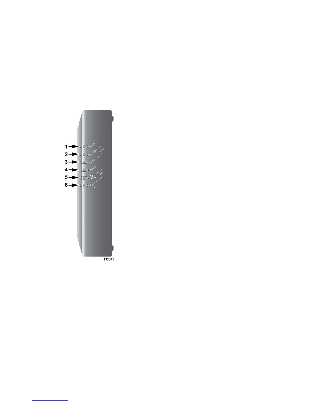
DPR2320 and EPR2320 Front Panel LED Status Indicators
The front panel of your cable modem gateway provides LED status indicators that
indicate how well and at what state your cable modem gateway is operating. See
DPR2320 and EPR2320 Front Panel LED Status Indicator Functions (on page 122)
for more information on front panel LED status indicator functions.
1 POWER—Illuminates solid green to indicate that
power is being applied to the cable modem gateway
2 RECEIVE DATA—Blinks to indicate that the cable
modem gateway is receiving data from the cable
network
3 SEND DATA—Blinks to indicate that the cable
modem gateway is sending data to the cable network
4 CABLE—Illuminates solid green when the cable
modem gateway is registered on the network and
fully operational. This indicator blinks to indicate one
of the following conditions:
- The cable modem gateway is booting up and not
ready for data
- The cable modem gateway is scanning the
network and attempting to register
- The cable modem gateway has lost registration
on the network and will continue blinking until it
registers again
5 PC (Ethernet/USB)—Illuminates solid green to
indicate that an Ethernet/USB carrier is present and
blinks to indicate that Ethernet/USB data is being
transferred between the PC and the cable modem
gateway
6 PC (Wireless)—Illuminates solid green to indicate
that a wireless access point is enabled and blinks to
indicate that wireless data is being transferred over
the wireless connection
Note: After the cable modem gateway is successfully
registered on the network, the POWER (LED 1) and
CABLE (LED 4) indicators illuminate continuously to
indicate that the cable modem gateway is online and
fully operational.
Page 21
Cable Modem Gateway Components
68-4004214-01 Rev D 5
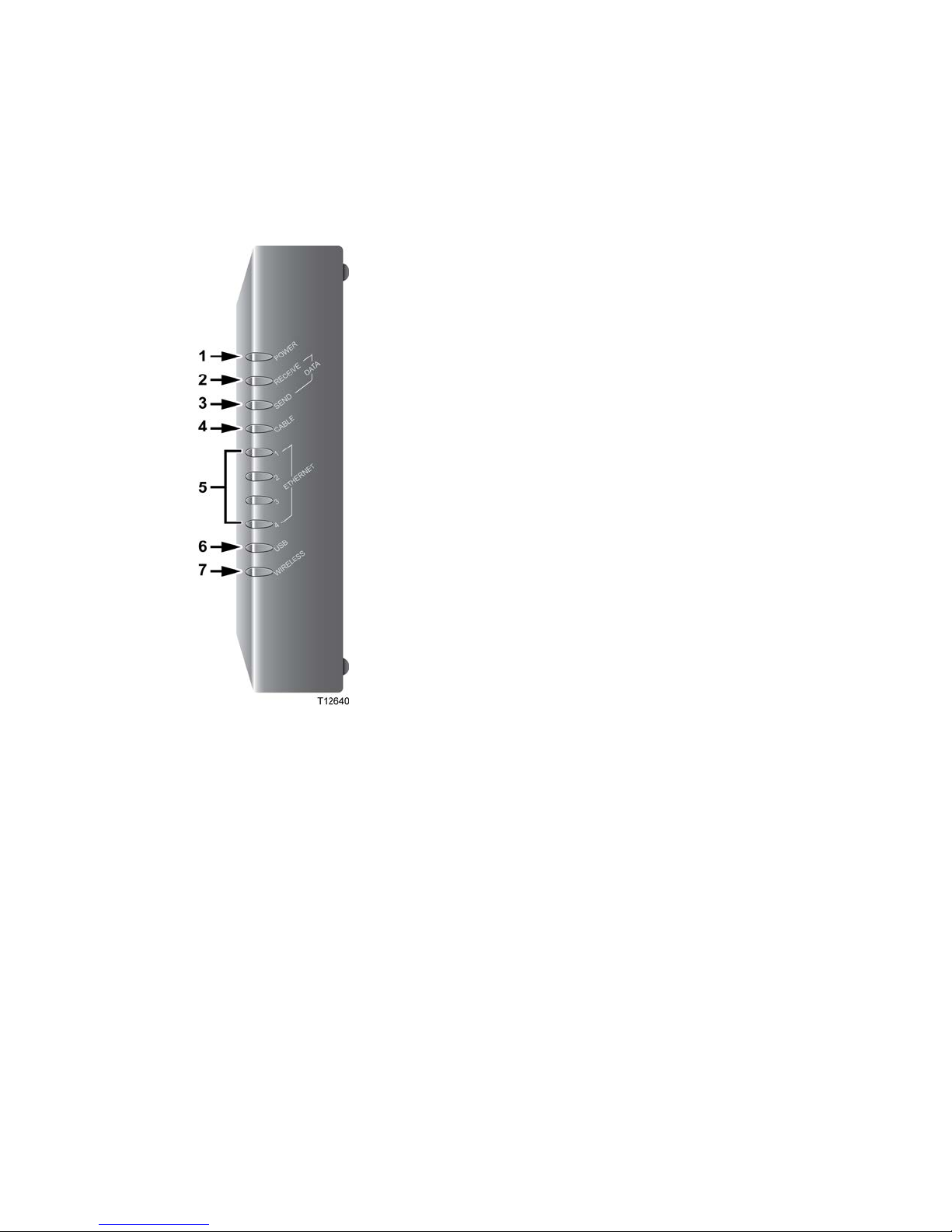
DPR2325 and EPR2325 Front Panel LED Status Indicators
The front panel of your cable modem gateway provides LED status indicators that
indicate how well and at what state your cable modem gateway is operating. See
DPR2325 and EPR2325 Front Panel LED Status Indicator Functions (on page 124)
for more information on front panel LED status indicator functions.
1 POWER—Illuminates solid green to indicate that
power is being applied to the cable modem gateway
2 RECEIVE DATA—Blinks to indicate that the cable
modem gateway is receiving data from the cable
network
3 SEND DATA—Blinks to indicate that the cable
modem gateway is sending data to the cable network
4 CABLE—Illuminates solid green when the cable
modem gateway is registered on the network and
fully operational. This indicator blinks to indicate one
of the following conditions:
- The cable modem gateway is booting up and not
ready for data
- The cable modem gateway is scanning the
network and attempting to register
- The cable modem gateway has lost registration
on the network and will continue blinking until it
registers again
5 ETHERNET (1-4)—Illuminates solid green to
indicate that an Ethernet carrier is present and blinks
to indicate that Ethernet data is being transferred
between the PC and the cable modem gateway
6 USB—Illuminates solid green to indicate that a USB
carrier is present and blinks to indicate that data is
being transferred on a USB connection to the cable
modem gateway
7 Wireless—Illuminates solid green to indicate that a
wireless access point is enabled and blinks to indicate
that wireless data is being transferred over the
wireless connection
Note: After the cable modem gateway is successfully
registered on the network, the POWER (LED 1) and
CABLE (LED 4) indicators illuminate continuously to
indicate that the cable modem gateway is online and
fully operational.
Page 22
Chapter 1 Introducing the Model DPR2320, DPR2325, EPR2320, and EPR2325 Cable Modem Gateways
6 68-4004214-01 Rev D
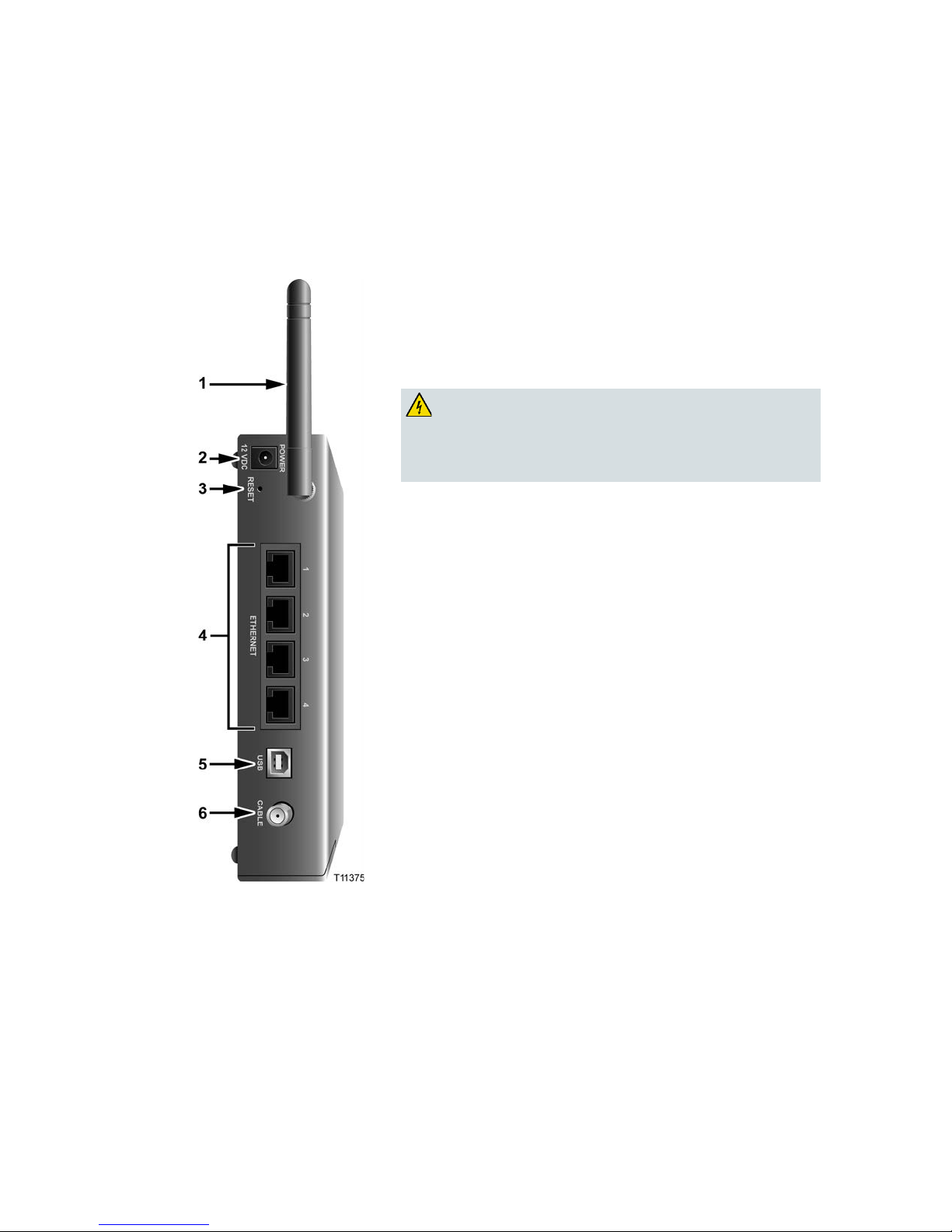
DPR2325 and EPR2325 Back Panel Components
The following illustration shows the description and function of the back panel
components of the DPR2325 and EPR2325 cable modem gateways.
Important: Do not connect your PC to both the Ethernet and USB ports at the same
time. Your Internet service may not function properly if both the Ethernet and USB
ports are connected to the same PC at the same time.
1 ANTENNA—Provides a communication connection for the
built-in wireless access point (WAP) to allow wireless devices
to communicate with the cable modem
2 POWER—Connects the cable modem to the DC output of the
AC power adapter that is provided with your cable modem
CAUTION:
Avoid damage to your equipment. Only use the
AC power adapter that is provided with your cable
modem gateway.
3 RESET—Activating this switch resets the cable modem
gateway to factory default values and reboots the cable
modem gateway
Note: This switch is for maintenance purposes only. Do not
use unless directed to do so by your service provider.
4 ETHERNET—One RJ-45 Ethernet port (on DPR2320 and
EPR2320 modems) or four RJ-45 Ethernet ports (on DPR2325
and EPR2325 modems) connect to the Ethernet port on your
PC or to an Ethernet hub or router on your home network
5 USB—12 Mbps USB port connects to the USB port on your
PC
6 CABLE—F-connector connects to an active cable signal from
your service provider
Page 23

Cable Modem Gateway Components
68-4004214-01 Rev D 7
DPR2320 and EPR2320 Back Panel Components
The following illustration shows the description and function of the back panel
components of the DPR2320 and EPR2320 cable modem gateways.
Important: Do not connect your PC to both the Ethernet and USB ports at the same
time. Your Internet service may not function properly if both the Ethernet and USB
ports are connected to the same PC at the same time.
1 ANTENNA—Provides a communication connection for the
built-in wireless access point (WAP) to allow wireless
devices to communicate with the cable modem gateway
2 POWER—Connects the cable modem gateway to the DC
output of the AC power adapter that is provided with your
cable modem gateway
CAUTION:
Avoid damage to your equipment. Only use the AC
power adapter that is provided with your cable
modem gateway.
3 RESET—Activating this switch resets the cable modem
gateway to factory default values and reboots the cable
modem gateway
Note: This switch is for maintenance purposes only. Do not
use unless directed to do so by your service provider.
4 ETHERNET—One RJ-45 Ethernet port (on DPR2320 and
EPR2320 modems) or four RJ-45 Ethernet ports (on
DPR2325 and EPR2325 modems) connect to the Ethernet
port on your PC or to an Ethernet hub or router on your
home network
5 USB—12 Mbps USB port connects to the USB port on your
PC
6 CABLE—F-connector connects to an active cable signal
from your service provider
Page 24

Chapter 1 Introducing the Model DPR2320, DPR2325, EPR2320, and EPR2325 Cable Modem Gateways
8 68-4004214-01 Rev D
Theory of Operation
This section summarizes the theory of operation for cable modem gateways and
provides a high-level overview of the operational stages for the cable modem
gateway. Reading this chapter provides a better understanding of how cable modem
gateways operate.
Note: This section is not intended to be a specification for the cable modem gateway.
Cable Modem Initialization
A cable modem gateway must establish a communication link with the headend
before it becomes fully operational. This section describes the eight DOCSISrequired operational stages through which a cable modem gateway progresses in
establishing this communication link.
This section provides a detailed explanation of each of the following operational
stages.
1 Scan for Downstream Channel
2 Obtain Upstream Parameters
3 Adjust Timing Offset and Power Level
4 Establish IP Connectivity
5 Establish Time of Day
6 Transfer Operational Parameters
7 Register with the Cable Modem Termination System (CMTS)
8 Initialize Baseline Privacy
Scan for Downstream Channel
When a cable modem gateway powers on, the cable modem gateway starts to scan
the network for the CMTS downstream channel. The downstream channel is the
channel used to send data from the CMTS to the cable modem gateway. The cable
modem gateway identifies a valid downstream data channel as a channel that has
QAM signal timing, forward error correction (FEC) framing, MPEG packets, and
downstream media access control (MAC) messages. The CMTS terminates the cable
modem gateway signal at an upstream location and provides the cable modem
gateway with a network connection.
This section discusses the cable modem gateway downstream scanning routine
along with two features that speed up the downstream scanning process: the Valid
CMTS Frequency Table and the WebWizard Gscan function.
Page 25

Theory of Operation
68-4004214-01 Rev D 9
Downstream Scanning Routi ne
The cable modem gateway starts its own standard scanning algorithm. The scanning
routine of the cable modem gateway is now optimized to seek out the CMTS
downstream channel as quickly as possible. The actual scanning process varies
slightly depending on the television frequency channel plan for your particular
country.
For example, in North America the standard downstream scanning routine works in
three phases and may take several minutes. The cable modem gateway stops
scanning when the cable modem gateway finds a valid downstream data channel.
The cable modem gateway then proceeds to the next stage: obtain upstream
parameters.
In this example, the cable modem gateway scans for the downstream channel in the
following three phases.
1 The cable modem gateway starts to scan the network at 453 MHz and scans up in
6 MHz increments to end at 855 MHz.
2 The cable modem gateway starts scanning the network at 447 MHz and then
scans in 6 MHz increments down to 93 MHz.
3 The process is then repeated for the National Television Systems Committee
(NTSC) Harmonic Related Carrier (HRC) frequency plan in 6.0003 MHz
increments.
Important: There are specialized frequency plans to optimize the acquisition of the
downstream signal that depend on the video format used in the country of
deployment. Check with the representative who handles your account for more
information about alternate scanning routines outside of North America.
Improved Downstream Scann ing Features
The cable modem gateways contain two outstanding features that can speed up the
scanning process: the Valid CMTS Frequency Table and the WebWizard Gscan
function.
Valid CMTS Frequency Table
The Valid CMTS Frequency Table feature works automatically and requires no user
intervention. When a cable modem gateway finds a valid downstream data channel
so that it can complete the ranging stage, the cable modem gateway stores this
frequency in nonvolatile memory (NVM). The cable modem gateway checks the
frequencies stored in NVM before starting the standard scanning algorithm to search
for a downstream data channel.
Note: The cable modem gateways store up to 10 valid CMTS frequencies in the table.
The standard scanning algorithm also regularly interrupts progressive scanning to
check the last known valid CMTS frequency, and then the cable modem gateway
resumes its standard scanning algorithm where it left off.
Page 26

Chapter 1 Introducing the Model DPR2320, DPR2325, EPR2320, and EPR2325 Cable Modem Gateways
10 68-4004214-01 Rev D
WebWizard Gscan Function
When installing a cable modem gateway, you can speed up the process by using the
WebWizard Gscan function. To access the WebWizard Gscan function, you must
first connect a PC to the cable modem. Then, using your Web Browser, you can
access the WebWizard Gscan function.
Note: For more information on the WebWizard Gscan function, see WebWizard
(on page 106).
Obtain Upstream Parameters
After finding a valid downstream data channel, the cable modem gateway reviews
the upstream parameters needed to perform the next stage: ranging and automatic
adjustments. The upstream parameters enable the cable modem gateway to send
data to the CMTS. When the cable modem gateway finds the correct upstream
parameters, the cable modem gateway proceeds to the ranging and automatic
adjustments stage.
If the cable modem gateway cannot find valid upstream parameters, it returns to the
scan for downstream channel stage. Then the cable modem gateway starts to scan
again at the next available channel.
Adjust Timing Offset and Power Level
After the cable modem gateway obtains its upstream parameters, it begins the
ranging and automatic adjustments stage. In this stage, the cable modem gateway
adjusts the timing offset and the power level for communicating with the CMTS.
The cable modem gateway uses MAC messages to determine the upstream channel
frequency and adjusts timing offsets to verify the synchronized timing between the
CMTS and the cable modem gateway. This process also determines the upstream
signal transmit power level from the cable modem gateway to communicate with the
CMTS.
After the cable modem gateway completes the ranging stage and registers with the
CMTS, it repeats this routine regularly to fine-tune the settings established in the
previous stages. These regular adjustments are considered routine maintenance and
do not affect normal operations of your cable modem gateway service.
Note: If the cable modem gateway fails to achieve the proper settings when
performing ranging and automatic adjustments, it terminates the session and restarts
the initialization process at the scan for downstream channel stage.
Page 27

Theory of Operation
68-4004214-01 Rev D 11
Establish IP Connectivity
After completing the ranging and automatic adjustments stage, the cable modem
gateway attempts to establish Internet Protocol (IP) connectivity. In this stage, the
cable modem gateway obtains network connection information and a cable modem
gateway IP address from provisioning servers that are located on the network side of
the CMTS interface.
The cable modem gateway achieves this connectivity using a protocol called
Dynamic Host Configuration Protocol (DHCP).
Note: If the cable modem gateway fails to establish IP connectivity, it terminates the
session and restarts the initialization process at the scan for downstream channel
stage.
Establish Time of Day
After the cable modem gateway establishes IP connectivity, the cable modem
gateway requests the time of day from the network interface. This stage allows the
cable modem gateway to know the system time so that when the cable modem
gateway logs an event, it associates a time with that event.
Note: The cable modem gateway can operate without establishing the time of day;
however, it logs the failure, generates an alert to simple network management
protocol (SNMP), and then proceeds to the next stage. The cable modem gateway
periodically repeats this stage to attempt to establish the time of day.
Tr ansfer Operational Parameters
After the cable modem gateway requests the time of day, the cable modem gateway
then requests the transfer of the cable modem gateway configuration file. The cable
modem gateway makes the request to the Trivial File Transfer Protocol (TFTP)
server. The configuration file contains parameters for how the system operator
wants the cable modem gateway to function on the cable network.
Typical operation parameters for the cable modem gateway include:
Upstream and downstream rate limits
Specific frequencies
Number of CPE devices
IP filters
Port filters
MAC/LLC filters
Vendor-specific settings
Software version installed
Page 28

Chapter 1 Introducing the Model DPR2320, DPR2325, EPR2320, and EPR2325 Cable Modem Gateways
12 68-4004214-01 Rev D
Notes:
If the cable modem gateway does not contain the software version requested by
the configuration file, the cable modem gateway requests that software version
from the TFTP server. When the software installation is complete, the cable
modem gateway restarts the entire initialization process again at the scan for
downstream channel stage.
If the system instructs the cable modem gateway to use a different frequency
from what the cable modem gateway is currently using, the cable modem
gateway cannot proceed to the next stage: register with the CMTS. The cable
modem gateway must repeat the scan for downstream channel stage or
reestablish ranging on a new upstream channel.
Register with the CMTS
After the cable modem gateway completes the transfer operational parameters stage,
the cable modem gateway now registers with the CMTS. After the cable modem
gateway receives a reply from the CMTS confirming its registration request, the
cable modem gateway is now authorized to forward network traffic from the CPE.
Initialize Baseline Privacy
Baseline Privacy functions in the CMTS and in the cable modem gateway are used to
encrypt data being transferred to and from the cable modem gateway. Following
registration with the CMTS, if the cable modem gateway is provisioned to run with
baseline privacy, the cable modem gateway must initialize baseline privacy
operations. Using baseline privacy means that all data transferred is secure.
Page 29

68-4004214-01 Rev D 13
Introduction
This chapter provides information and procedures to assist you in
placing, installing, configuring, operating, and troubleshooting the
DPR2320/DPR2325/EPR2320/EPR2325 for high-speed Internet
service.
2 Chapter 2
Installing the Cable Modem
Gateway for Internet Service
In This Chapter
Before You Begin ................................................................................... 14
Where Is the Best Location for My Cable Modem Gateway? ......... 17
How Do I Mount the Cable Modem Gateway on the Wall? ........... 18
Configure TCP/IP ................................................................................ 20
Install USB Drivers ............................................................................... 23
Install the Cable Modem Gateway ..................................................... 25
Page 30

Chapter 2 Installing the Cable Modem Gateway for Internet Service
14 68-4004214-01 Rev D
Before You Begin
This section provides the minimum requirements for installing the cable modem
gateways on your system and at user sites.
Cable System Requirements
To allow successful installation and operation, verify that your system meets the
following minimum requirements:
For the DPR2320 and DPR2325: DOCSIS 2.0, 1.1, or 1.0
For the EPR2320 and EPR2325: EuroDOCSIS 2.0, 1.1, or 1.0
Important: This guide does not cover installing cable modem gateway network and
headend equipment on your system. For information on installing network and
headend equipment, refer to the documentation provided with your network and
headend equipment.
Equipment Checklist
Before you install the cable modem gateway, check the items in the carton. The
carton contains the following items, except as noted:
One DPR2320, DPR2325, EPR2320, or EPR2325 cable modem gateway
One Ethernet cable (CAT5/RJ-45)
One USB cable
One AC power adapter
One CD-ROM containing the user’s guide and the USB drivers
Notes:
An additional cable signal splitter and coaxial cable are needed to connect to a
VCR, a digital set-top converter, or a TV to the same cable connection as your
cable modem gateway.
Cables and other equipment needed for telephony service must be purchased
separately.
Page 31

Before You Begin
68-4004214-01 Rev D 15
Hardware and Softw are Requireme nts
This section provides hardware and software requirements for connecting your
cable modem gateway to a PC for high-speed Internet service.
Note: You will also need an active cable input line and an Internet connection.
PC Requirements
A PC with a Pentium MMX 133 processor or greater
32 MB of RAM
Netscape or Internet Explorer
CD-ROM drive
Macintosh Requirements
MAC OS 7.5 or later
32 MB of RAM
Ethernet Requirements
A PC with Microsoft Windows 95 operating system (or later) with TCP/IP
protocol installed, or an Apple Macintosh computer with TCP/IP protocol
installed
An active 10/100BASE-T Ethernet network interface card (NIC) installed in your
PC
USB Requirements
A PC with a Microsoft Windows 2000 or XP operating system
A host USB port installed in your PC
Contacting Y our Local Service Provider
Before you can use your cable modem gateway, you need to have a high-speed
Internet access account. If you do not have a high-speed Internet access account, you
need to set up an account with your local service provider. Choose one of the two
options in this section.
Page 32

Chapter 2 Installing the Cable Modem Gateway for Internet Service
16 68-4004214-01 Rev D
I Do Not Have a High-Speed Internet Access Account
If you do not have a high-speed Internet access account, your service provider will
set up your account and become your Internet Service Provider (ISP). Internet access
enables you to send and receive e-mail, access the World Wide Web, and receive
other Internet services.
You will need to give your service provider the following information:
The serial number of the modem
The Media Access Control (MAC) address of the modem
The WAN DATA MAC address of the modem
These numbers appear on a bar code label located on the cable modem gateway. The
serial number consists of a series of alphanumeric characters preceded by S/N. The
MAC address consists of a series of alphanumeric characters preceded by MAC. The
WAN Data MAC address consists of a series of alphanumeric characters preceded
by WAN DATA MAC. The following illustration shows a sample bar code label.
Note: Due to minor design changes, the label on your cable modem gateway may
differ slightly from the one shown here.
Write down these numbers in the space provided here.
Serial Number _______________________
MAC Address _______________________
WAN DATA MAC Address ________________________
I Already Have an Existing High-Speed Internet Access Account
If you have an existing high-speed Internet access account, you must give your
service provider the serial number and the MAC address of the cable modem
gateway. Refer to the serial number and MAC address information listed previously
in this section.
Note: You might not be able to continue to use your existing e-mail account with
your cable modem gateway. Contact your service provider for more information.
Page 33

Where Is the Best Location for My Cable Modem Gateway?
68-4004214-01 Rev D 17
Where Is the Best Location for My Cable Modem
Gateway?
The ideal location for your cable modem gateway is where it has access to outlets
and other devices. Think about the layout of your home or office, and consult with
your service provider to select the best location for your cable modem gateway.
Read this user's guide thoroughly before you decide where to place your cable
modem gateway.
Consider these recommendations:
Position your PC and cable modem gateway so that they are located near an AC
power outlet.
Position your PC and cable modem gateway so that they are located near an
existing cable input connection to eliminate the need for an additional cable
outlet. There should be plenty of room to guide the cables away from the modem
and the PC without straining or crimping them.
Airflow around the cable modem gateway should not be restricted.
Choose a location that protects the cable modem gateway from accidental
disturbance or harm.
Page 34

Chapter 2 Installing the Cable Modem Gateway for Internet Service
18 68-4004214-01 Rev D
How Do I Mount the Cable Modem Gateway on the
Wall?
Before Y ou Begin
Before you begin, choose an appropriate mounting place. The wall can be made of
cement, wood, or drywall. The mounting location should be free of obstructions on
all sides, and the cables should be able to easily reach the cable modem gateway
without strain. Leave sufficient clearance between the bottom of the cable modem
gateway, and any flooring or shelving underneath, to allow access to cabling. In
addition, leave enough slack in all cables so that the cable modem can be removed
for any required maintenance without disconnecting the cables. Also, verify that you
have the following items:
Two wall anchors for #8 x 1 inch screws
Two #8 x 1 inch pan head sheet metal screws
Drill with a 3/16-in. wood or masonry bit
A copy of the wall-mounting illustrations shown on the following pages
Mounting Instructions
You can mount the DPR2320/DPR2325/EPR2320/EPR2325 cable modem gateway
directly on a wall using two wall anchors, two screws, and the mounting slots on the
bottom of the modem. The modem can be mounted vertically or horizontally.
Page 35

How Do I Mount the Cable Modem Gateway on the Wall?
68-4004214-01 Rev D 19
Location and Dimensions of the Wall-Mounting Slots
The following illustration shows the location and dimensions of the wall-mounting
slots on the bottom of the modem. Use the information on this page as a guide for
mounting your modem to the wall.
Wall Mounting Instructions
Complete these steps to mount the modem to the wall.
1 Using a drill with a 3/16-in bit, drill two holes at the same height and 4 inches
apart.
2 Are you mounting the cable modem gateway into a drywall or concrete surface
where a wooden stud is not available?
If yes, drive the anchor bolts into the wall and then go to step 3.
If no, go to step 3.
3 Install the mounting screws into the wall or the anchor bolts, as appropriate, and
leave a gap of about 1/4-in. between the screw head and the wall.
4 Verify that no cables or wires are connected to the cable modem.
5 Lift the cable modem gateway into position. Slip the large end of both mounting
slots (located on the back of the modem) over the mounting screws, and then
slide the modem down until the narrow end of the keyhole slot contacts the shaft
of the screw.
Important: Verify that the mounting screws securely support the modem before
you release the unit.
Page 36

Chapter 2 Installing the Cable Modem Gateway for Internet Service
20 68-4004214-01 Rev D
Configure TCP/IP
This section contains instructions for configuring the cable modem gateway to run in
Microsoft Windows or Macintosh environments. In addition, TCP/IP protocol in a
Microsoft Windows environment is different for the Windows 95, 98, 98SE, ME,
2000, or XP versions. Go to the appropriate section and follow the instructions to
configure the TCP/IP protocol.
Configuring TCP/IP on Windows 95, 98, 98SE, or ME Systems
1 Click Start, select Settings, and choose Control Panel.
2 Double-click the Network icon in the Control Panel window.
3 Read the list of installed network components under the Configuration tab to
verify that your PC contains the TCP/IP protocol/Ethernet adapter.
4 Is TCP/IP protocol listed in the installed network components list?
If yes, go to step 7.
If no, click Add, click Protocol, click Add, and then go to step 5.
5 Click Microsoft in the Manufacturers list.
6 Click TCP/IP in the Network Protocols list, and then click OK.
7 Click the TCP/IP Ethernet Adapter protocol, and then choose Properties.
8 Click the IP Address tab, and then select Obtain an IP address automatically.
9 Click the Gateway tab and verify that these fields are empty. If they are not
empty, highlight and delete all information from the fields.
10 Click the DNS Configuration tab, and then select Disable DNS.
11 Click OK.
12 Click OK when the system finishes copying the files, and then close all
networking windows.
13 Click YES to restart your computer when the System Settings Change dialog box
opens. The computer restarts. The TCP/IP protocol is now configured on your
PC, and your Ethernet devices are ready for use.
14 Try to access the Internet. If you cannot access the Internet, go to Having
Difficulty? (on page 134). If you still cannot access the Internet, contact your
service provider for further assistance.
Configuring TCP/IP on Windows 2000 Systems
1 Click Start, select Settings, and choose Network and Dial-up Connections.
2 Double-click the Local Area Connection icon in the Network and Dial-up
Connections window.
3 Click Properties in the Local Area Connection Status window.
Page 37

Configure TCP/IP
68-4004214-01 Rev D 21
4 Click Internet Protocol (TCP/IP) in the Local Area Connection Properties
window, and then click Properties.
5 Select both Obtain an IP address automatically and Obtain DNS server address
automatically in the Internet Protocol (TCP/IP) Properties window, and then
click OK.
6 Click Yes to restart your computer when the Local Network window opens. The
computer restarts. The TCP/IP protocol is now configured on your PC, and your
Ethernet devices are ready for use.
7 Try to access the Internet. If you cannot access the Internet, go to Having
Difficulty? (on page 134). If you still cannot access the Internet, contact your
service provider for further assistance.
Configuring TCP/IP on Windows XP Systems
1 Click Start, and depending on your Start menu setup, choose one of the
following options:
If you are using the Windows XP Default Start Menu, select Connect to,
choose Show all connections, and then go to step 2.
If you are using the Windows XP Classic Start Menu, select Settings, choose
Network Connections, click Local Area Connection, and then go to step 3.
2 Double-click the Local Area Connection icon in the LAN or High-Speed Internet
section of the Network Connections window.
3 Click Properties in the Local Area Connection Status window.
4 Click Internet Protocol (TCP/IP), and then click Properties in the Local Area
Connection Properties window.
5 Select both Obtain an IP address automatically and Obtain DNS server address
automatically in the Internet Protocol (TCP/IP) Properties window, and then
click OK.
6 Click Yes to restart your computer when the Local Network window opens. The
computer restarts. The TCP/IP protocol is now configured on your PC, and your
Ethernet devices are ready for use.
7 Try to access the Internet. If you cannot access the Internet, go to Having
Difficulty? (on page 134). If you still cannot access the Internet, contact your
service provider for further assistance.
Configuring TCP/IP on Macintosh Systems
1 Click the Apple icon in the upper-left corner of the Finder. Scroll down to
Control Panels, and then click TCP/IP.
2 Click Edit on the Finder at the top of the screen. Scroll down to the bottom of the
menu, and then click User Mode.
3 Click Advanced in the User Mode window, and then click OK.
Page 38

Chapter 2 Installing the Cable Modem Gateway for Internet Service
22 68-4004214-01 Rev D
4 Click the Up/Down selector arrows located to the right of the Connect Via
section of the TCP/IP window, and then click Using DHCP Server.
5 Click Options in the TCP/IP window, and then click Active in the TCP/IP
Options window.
Note: Make sure that the Load only when needed option is unchecked.
6 Verify that the Use 802.3 option located in the upper-right corner of the TCP/IP
window is unchecked. If there is a check mark in the option, uncheck the option,
and then click Info in the lower-left corner.
7 Is there a Hardware Address listed in this window?
If yes, click OK. To close the TCP/IP Control Panel window, click File, and
then scroll down to click Close. You have completed this procedure.
If no, you must power off your Macintosh.
8 With the power off, simultaneously press and hold down the Command
(Apple), Option, P, and R keys on your keyboard. Keeping those keys pressed
down, power on your Macintosh but do not release these keys until you hear the
Apple chime at least three times, then release the keys and let the computer
restart.
9 When your computer fully reboots, repeat steps 1 through 7 to verify that all
TCP/IP settings are correct. If your computer still does not have a Hardware
Address, contact your authorized Apple dealer or Apple technical support center
for further assistance.
Page 39

Install USB Drivers
68-4004214-01 Rev D 23
Install USB Drivers
This section contains instructions for installing the cable modem gateway USB
drivers if your PC is equipped with a USB interface and a Microsoft Windows 2000
or Windows XP operating system. The USB driver installation procedures are
different for each operating system. Follow the appropriate instructions in this
section for your operating system.
Note: If your PC does not have a USB interface, you may skip this section.
Installing USB Drivers on Windows 2000 Systems
1 Insert the USB Cable Modem Driver Installation Disk into the CD-ROM drive
of your PC.
2 Wait until the POWER and ONLINE LED status indicators on the front panel of
the cable modem gateway illuminate solid green.
3 Click Next in the Found New Hardware Wizard window.
4 Select Search for a suitable driver for my device (recommended) in the Found
New Hardware Wizard window, and then click Next.
5 Select CD-ROM drives in the Found New Hardware Wizard window, and then
click Next.
6 Click Next in the Found New Hardware Wizard window. The system searches
for the driver file for your hardware device.
7 After the system finds the USB driver, the Digital Signature Not Found window
opens and displays a confirmation message to continue the installation.
8 Click Yes to continue the installation. The Found New Hardware Wizard
window reopens with a message that the installation is complete.
9 Click Finish to close the Found New Hardware Wizard window. The USB
drivers are installed on your PC, and your USB devices are ready for use.
10 Try to access the Internet. If you cannot access the Internet, go to Having
Difficulty? (on page 134). If you still cannot access the Internet, contact your
service provider for further assistance.
Installing USB Drivers on Windows XP Systems
1 Insert the USB Cable Modem Driver Installation Disk into the CD-ROM drive
of your PC.
2 Wait until the POWER and ONLINE LED status indicators on the front panel of
the cable modem gateway illuminate solid green.
3 Select Install from a list or specific location (Advanced) in the Found New
Hardware Wizard window, and then click Next.
4 Select Search removable media (floppy, CD-ROM) in the Found New
Hardware Wizard window, and then click Next.
Page 40

Chapter 2 Installing the Cable Modem Gateway for Internet Service
24 68-4004214-01 Rev D
5 Click Continue Anyway in the Hardware Installation window to continue the
installation. The Found New Hardware Wizard window reopens with a message
that the installation has finished.
6 Click Finish to close the Found New Hardware Wizard window. The USB
drivers are installed on your PC, and your USB devices are ready for use.
7 Try to access the Internet. If you cannot access the Internet, go to Having
Difficulty? (on page 134). If you still cannot access the Internet, contact your
service provider for further assistance.
Page 41

Install the Cable Modem Gateway
68-4004214-01 Rev D 25
Install the Cable Modem Gateway
Installation Diagram
The following diagram illustrates one of the various installation and connection
options that are available to you.
Note: Professional installation may be available. Contact your local service provider
for further assistance.
Page 42

Chapter 2 Installing the Cable Modem Gateway for Internet Service
26 68-4004214-01 Rev D
Connecting the Modem for High-Speed Data Service
WARNING:
To avoid personal injury or damage to your equipment, follow these steps in
the exact order shown.
1 Power off your PC and unplug it from the power source.
2 Connect your PC to either the ETHERNET port or the USB port using the
appropriate data cable. Do not connect your PC to both the Ethernet and USB
ports at the same time. You can connect two separate PCs to the cable modem
gateway at the same time by connecting one PC to the Ethernet port and one PC
to the USB port.
3 Connect the active RF coaxial cable to the CABLE connector. Use an optional
cable signal splitter to add a TV, a DHCT or set-top converter, or a VCR.
4 Insert the AC power cord into the POWER connector on the back of the cable
modem gateway, and then plug the cord into an AC power source.
5 Plug in and power on your networked devices including your PC. The cable
modem gateway will then begin an automatic search to locate and sign on to the
broadband data network. This process may take up to 5 minutes. The modem
will be ready for use when the CABLE LED status indicator on the front panel
stops blinking and illuminates continuously.
6 The next step in setting up your cable modem gateway is to configure your
Internet devices for Internet access. Choose one of the following options:
If you want to use Ethernet connections, you must configure the TCP/IP
protocol. To configure the TCP/IP protocol, go to Configure TCP/IP
(on page 20).
If you want to use USB connections, you must install the USB drivers. To
install the USB Drivers for USB, go to Install USB Drivers (on page 23).
Page 43

68-4004214-01 Rev D 27
Introduction
This chapter provides procedures for configuring the basic operational
features of the DPR2320/DPR2325/EPR2320/EPR2325. This chapter
also provides a description of the basic features along with sample
WebWizard HTML pages.
Access to these HTML pages is defined and configured by the system
operator; therefore, you may or may not have access to the
WebWizard. The system operator can enable other pages after
registration by using a configuration variable.
3 Chapter 3
Basic Configuration
In This Chapter
Configure Basic Settings ...................................................................... 28
Page 44

Chapter 3 Basic Configuration
28 68-4004214-01 Rev D
Configure Basic Settings
Accessing the Cable Modem Gateway
You must access the WebWizard in order to configure the cable modem gateway. To
gain access to the WebWizard, use the Web browser on the PC attached to the
gateway and complete the following steps.
1 Type the following IP address and then select Go:
http://192.168.0.1. An authentication window similar to the following window
opens.
2 Leave the User Name field blank and enter your password in the Password field.
The Web browser accesses the WebWizard and displays the default About Your
Modem page. This page displays information about your cable modem along
with a series of tabs for accessing other WebWizard configuration and operation
features.
Page 45

Configure Basic Settings
68-4004214-01 Rev D 29
About Your Modem Page Example
The following illustration is an example of the About Your Modem page.
About Your Modem Page Description
The following tables provide a description of each field within the About Your
Modem page.
System Section
Field Name Description
Name The name of the cable modem gateway
Modem Serial Number A unique sequential series of alphanumeric
characters provided to every modem during
manufacturing
Cable Modem MAC
Address
A unique alphanumeric address for the cable
modem coaxial interface, which is used to connect
to the cable modem termination system (CMTS) at
the headend. A media access control (MAC)
address is a hardware address that uniquely
identifies each node of a network
Page 46

Chapter 3 Basic Configuration
30 68-4004214-01 Rev D
Field Name Description
Hardware Version Identifies the revision of the circuit board design
Software Version Identifies the software version placed into the
modem at the time of manufacturing
Receive Power Level The input level of the downstream CMTS carrier
Transmit Power Level Indicates the upstream power level
Cable Modem Status Lists one of the following possible current states of
the modem:
other
notReady
notSynchronized
phySynchronized
usParametersAcquired
rangingComplete
ipComplete
todEstablished
securityEstablished
psrsmTransferComplete
registrationComplete
operational
accessDenied
Vendor
The name of the manufacturer
Boot Revision
Identifies the boot revision code version
Software Revision
Identifies the software version placed into the
cable modem gateway at the time of
manufacturing
Software Build and Revisions Section
Field Name Description
Firmware Name Identifies the version of the firmware
Firmware Build Time Identifies the time and date that the firmware was
built
Page 47

Configure Basic Settings
68-4004214-01 Rev D 31
Setting Configuration Options
Click the Setup tab located in the upper portion of the About Your Modem screen to
access the Setup page. Use the Setup page to access the various configuration
options for the cable modem gateway. Detailed descriptions of each configuration
option follow later in this guide.
Setup Page Example
The following illustration is an example of the Setup page.
Setup Page Section Headings
The Setup page is divided into the following section headings:
Basic Settings
Advanced Settings
Firewall
Page 48

Chapter 3 Basic Configuration
32 68-4004214-01 Rev D
Parental Control
Wireless
In the Setup page, click the selections listed within these sections to access the
WebWizard page for that selection. A description of the selections available in each
section follows next.
Basic Settings
The following table provides a description of the pages available from within the
Basic Settings section of the Setup page.
Field Name Description
Password Settings Use this page to set or modify your password settings
Set Time Use this page to enable or disable time synchronization
by Network Time protocol
Network Configuration Use this page to enter or modify the basic settings for
your network
LAN IP Address
Management
Use this page to configure how Internet protocol (IP)
addresses are assigned and managed in your network
Fixed CPE IP Assignment Use this page to reserve IP addresses in the DHCP pool
that will be used as static IP addresses in your local
network
Restart Modem Use this page to restart your cable modem gateway
Save Configuration to
your PC
Use this page to save your cable modem RG
configuration to your local PC and to restore the RG
configuration to your cable modem gateway, if
necessary
Advanced Settings
The following table provides a description of the pages available from within the
Advanced Settings section of the Setup page.
Field Name Description
Options Use this page to enable or disable advanced features
on your network
IP Address Filtering Use this page to configure IP address filters. These
filters prevent designated IP addresses from accessing
the Internet
MAC Address Filtering Use this page to configure MAC address filters. These
filters prevent designated MAC addresses from
accessing the Internet
Page 49

Configure Basic Settings
68-4004214-01 Rev D 33
Field Name Description
Port Filtering Use this page to configure transmission control
protocol (TCP) and user datagram protocol (UDP) port
filters. These filters prevent a range of TCP/UDP ports
from accessing the Internet
Port Forwarding Use this page to configure port forwarding for local IP
addresses. Port forwarding allows you to run a server
on the local area network (LAN) by specifying the
mapping of TCP/UDP ports to local PCs or to the IP
address of other devices. This is a static setting that
holds the ports open at all times
Port Triggers Use this page to configure TCP/UDP port triggers.
Port triggering is similar to port forwarding, but is a
dynamic function. In other words, the ports are not
held open, and the ports close if no outgoing data is
detected on the selected ports for a period of 10
minutes
DMZ Host
(Demilitarized Zone)
Use this page to configure an IP address that is visible
to the wide area network (WAN). DMZ hosting is
commonly referred to as “exposed host,” and allows
you to specify the “default” recipient of WAN traffic
that Network Address Translation (NAT) is unable to
translate to a known local PC
A DMZ is used by a company that wants to host its
own Internet services without sacrificing unauthorized
access to its private network. DMZ allows one IP
address to be unprotected while others remain
protected. The DMZ is located between the Internet
and an internal network’s line of defense that is a
combination of firewalls and bastion hosts
Typically, the DMZ contains devices accessible to
Internet traffic, such as Web (HTTP) servers, FTP
servers, SMTP (e-mail) servers, and domain name
system (DNS) servers
IP Address Pass-through Use this page to bypass NAT by adding or deleting
passthrough CPEs
Advanced Networking
Features
Use this page to configure Routing Information
Protocol (RIP) parameters related to authentication, IP
addresses, subnet masks, and reporting intervals
VPN Termination Use this page to create, configure, and control Virtual
Private Network (VPN) protocols and manage Internet
Protocol Security (IPsec) VPN tunnels
Save Configuration to
Server
Use this page to save your configuration to the server
Page 50

Chapter 3 Basic Configuration
34 68-4004214-01 Rev D
Firewall
The following table provides a description of the pages available from within the
Firewall section of the Setup page.
Field Name Description
Options Use this page to configure webpage filtering and
firewall protection
Event Logging Use this page to access the firewall event log and
to enter your e-mail address in order to receive
e-mail alerts related to firewall attacks by hackers
Parental Control
The following table provides a description of the pages available from within the
Parental Control section of the Setup page.
Field Name Description
User Setup Use this page to add or delete user profiles and to
apply access rules to those users
Basic Rules Use this page to setup access rules that block
certain Internet content and certain websites
Time of Day Rules Use this page to configure Web access filters to
block all Internet traffic to and from specific
network devices based on time of day settings that
you select
Local Log Use this page to view events captured by Parental
Control event log feature
Page 51

Configure Basic Settings
68-4004214-01 Rev D 35
Wireless
The following table provides a description of the pages available from within the
Wireless section of the Setup page.
Field Name Description
Basic Use this page to configure your wireless access
point (WAP) parameters, including service set
identifier (SSID) and channel number
Security Use this page to configure your WAP
authentication and data encryption. Using
encryption and authentication prevents
unauthorized access to your wireless devices
Advanced Use this page to configure your WAP data rates
and wireless fidelity (WiFi) thresholds
Access Control Use this page to configure the WAP to restrict
access to only selected wireless client devices.
Authorized clients are selected by MAC address.
Use this page to select Open System or Share Key
authentication and to enable and disable broadcast
of the WAP SSID
Configuring Y our Password Settings
Use the Basic Settings - Password Settings page to set up a password to restrict
unauthorized persons from accessing to your cable modem gateway settings. Click
Password Settings in the Basic Settings section of the Setup page to access the
Password Settings page.
Notes:
Your cable modem gateway comes from the factory with no password enabled.
We highly recommend that you set up a user password to prevent unauthorized
users from modifying the settings of your network.
If you do choose to set up a password, use a password that you can easily
remember. Do not forget your password.
Page 52

Chapter 3 Basic Configuration
36 68-4004214-01 Rev D
Setup Basic Settings - Password Settings Page Example
The following illustration is an example of the Basic Settings - Password Settings
page.
To set up your password
To set up your password, type your password in the Password field, and then
re-type your password in the Re-Enter Password field. Then, click Apply to save
your password.
Note: If you set a password, on subsequent access to the WebWizard pages, a screen
similar to the following appears. Do not forget your password. Write your password
and store it in a secure location known only to you.
Configuring Network Time Synchronization
Use the Basic Settings Enable/Disable time synchronization by Network Time
protocol page to enable or disable time synchronization by Network Time protocol.
Page 53

Configure Basic Settings
68-4004214-01 Rev D 37
Note: If you are not familiar with the time configuration procedures detailed in this
section, contact your service provider before you attempt to change any of the cable
modem gateway default time synchronization configuration settings.
Click Set Time in the Basic Settings section of the Setup page to access the Basic
Settings Enable/Disable time synchronization by Network Time protocol page.
Setup Basic Settings - Enable/Disable Time Synchronization by Network Time Protocol Page
Example
The following illustration is an example of the Basic Settings Enable/Disable time
synchronization by Network Time protocol page.
Setup Basic Settings - Enable/Disable Time Synchronization by Network Time Protocol Page
Description
The following table provides a description of the fields within the Basic Settings
Enable/Disable time synchronization by Network Time protocol page.
Page 54

Chapter 3 Basic Configuration
38 68-4004214-01 Rev D
Field Name Description
Current System Time Displays the current system time and date
Network Time Protocol Allows you to enable or disable network time
protocol
Note: The cable modem gateway will
automatically use the time server in your
broadband network. Should there be no current
time displayed or if the network time is incorrect,
enable Network Time Protocol to use a public
Internet time server to set the clock in the gateway.
Latest Update Success Displays the time and date of the last successful
time update
Time Zone Displays the current time zone. The drop-down
list allows you to select your local time zone
Daylight Saving Time Allows you to adjust the time during periods
when Daylight Saving Time is in effect. Check the
Enable box to enable or disable this setting
Note: If the offset for Daylight Savings Time is
other than 60 minutes, enter the offset in the
minutes field.
Time Server Add and delete time server URLs or IP addresses
to and from the list, as required. When using
Network Time Protocol, multiple time servers can
be specified for the gateway to query for time of
day. The gateway will sequentially step through
the listed time servers until it acquires the current
time. There are three well known public time
servers entered as default servers
Function Keys
Key Description
Apply Saves all additions, edits, and changes
Add Server Allows you to add a network time server
Remove Server Allows you to remove a network time server
Configuring the Default Network Settings
You can use the default network settings, or if your system requires different
settings to operate correctly, you can change the default network settings using the
Setup Basic Settings - Network Configuration page.
Page 55

Configure Basic Settings
68-4004214-01 Rev D 39
Note: If you are not familiar with the network configuration procedures detailed in
this section, contact your service provider before you attempt to change any of the
cable modem gateway default network configuration settings.
Click Network Configuration in the Basic Settings section of the Setup page to
access the Setup Basic Settings - Network Configuration page.
Setup Basic Settings - Network Configuration Page Example
The following illustration is an example of the Setup Basic Settings - Network
Configuration page.
Setup Basic Settings - Network Configuration Page Description
The following table provides a description of the fields within the Setup Basic
Settings - Network Configuration page.
Page 56

Chapter 3 Basic Configuration
40 68-4004214-01 Rev D
Field Name Description
LAN IP
Address
Displays the base IP address of the private home LAN and
the WebWizard IP address. Your cable modem gateway
assigns private IP addresses to your attached computers by
its internal dynamic host configuration protocol (DHCP)
server
MAC Address Displays the MAC address for the WAN. The factory
assigned MAC address for the WAN is also referred to as the
WLAN Data MAC
WAN IP
Address
Displays the public IP address assigned to your gateway by
your ISP. The WAN port will be assigned a public IP address
automatically by your ISP except when a static IP address is
set up as described below. The WAN IP address will be
shared by all the PCs in your private local area network to
access the Internet
Subnet Mask Displays the subnet mask for your WAN port. This address
is automatically assigned to your WAN port by your ISP
except when a static IP address is set up as described later in
this table
Gateway IP Displays a Gateway IP address for your WAN port. This
address is automatically assigned to your WAN port by your
ISP except when a static IP address is set up as described
later in this table
Duration Displays the length of time your WAN IP address is valid
Expires Displays the date and time your WAN IP address expires
Host Name Displays the host name that is usually downloaded to your
gateway by your ISP. However, some ISPs require this
information to be entered manually. If manual entry is
required, your ISP will provide the information for you to
enter into this field.
Domain Name Displays the domain name that is usually downloaded to
your gateway by your ISP. However, some ISPs require this
information to be entered manually. If manual entry is
required, your ISP will provide the information for you to
enter into this field.
Static IP
Address
Manual entry is required. Your ISP will provide the
information for you to enter into this field.
Note: When setting a static IP address, you must enter the IP
address, subnet mask, and default gateway before the static
IP address will become operational.
Static IP Mask Manual entry is required. Your ISP will provide the
information for you to enter into this field
Page 57

Configure Basic Settings
68-4004214-01 Rev D 41
Field Name Description
Default
Gateway
Manual entry is required, your ISP will provide the
information for you to enter into this field
Primary DNS
(static IP only)
Manual entry is required. Your ISP will provide the
information for you to enter into this field
Secondary DNS
(static IP only)
Manual entry is required. Your ISP will provide the
information for you to enter into this field
Function Keys
The following function keys appear on the Setup Basic Settings - Network
Configuration page.
Key Description
Renew WAN IP
Address Lease
Forces a release and renewal of your WAN IP address
Apply Saves the values you enter into the fields without closing
the screen
Configuring and Managing IP Addresses
Use the Setup Basic Settings - IP Management page to configure how your system
manages and assigns IP addresses in your network.
Note: If you are not familiar with the IP management procedures detailed in this
section, contact your service provider before you attempt to change any of the cable
modem gateway default IP management settings.
Click LAN IP Address Management in the Basic Settings section of the Setup page
to access the Setup Basic Settings - IP Management page.
Page 58

Chapter 3 Basic Configuration
42 68-4004214-01 Rev D
Setup Basic Settings - IP Management Page Example
The following illustration is an example of the Setup Basic Settings - IP Management
page.
Page 59

Configure Basic Settings
68-4004214-01 Rev D 43
Setup Basic Settings - IP Management Page Description
The following tables provide a description of the fields within the Setup Basic
Settings - IP Management page.
Field Name Description
DHCP Server Allows you to enable or disable the DHCP server
in the cable modem gateway
Starting Local Address Displays the starting address used by the built-in
DHCP server to distribute Private LAN IP
addresses. In the example shown, addresses
between 2 and 9 can be used for devices on your
Private LAN that require fixed IP addresses such
as printers or a device assigned as a DMZ host
Note: The LAN IP address ending in 1 is reserved
for the internal gateway server. The LAN IP
address ending in 255 is also reserved and should
not be used for CPE devices.
Number of CPEs Enter the maximum number of devices allowed to
connect to the Private LAN
Note: The Factory Default is 245. The maximum
number of devices is 253. This is the combined
total of addresses reserved for static IP addresses,
for example, the sum of the IP addresses between
2 and the value entered in the Starting Local
Address field and the value entered in the
Number of CPEs field.
Note: The sum of the value entered in the Starting
Local Address field and the value entered in the
Number of CPEs field must always be 255 or less.
DHCP Client Lease Info Displays the MAC address, IP Address, Subnet
Mask, Duration and Expiration date of all devices
issued an IP address by the built-in DHCP server.
This field also displays the current system time
and date
Function Keys
The following function keys appear on the Basic Settings - IP Management page.
Key Description
Apply Saves the values you enter into the fields without
closing the screen
Force Available Forces the release of an IP address for you to
re-use
Page 60

Chapter 3 Basic Configuration
44 68-4004214-01 Rev D
Reserving IP Addresses
Use the Setup Basic Settings - Fixed CPE IP Assignment page to reserve IP
addresses. This feature allows you to assign a fixed IP address to any device in your
network by setting static IP addresses in your PC or other network device.
These addresses will be removed from the pool of the IP addresses to be used by
your gateway's DHCP server when issuing IP addresses to devices that are
connected to your local network.
Reserving IP addresses is useful in making sure that there are no IP address conflicts
on the network, for example, two devices using the same IP address. Another
example: when using DMZ Host, the IP address for the DMZ Host should always
have the same IP address.
Note: If you are not familiar with the Fixed CPE IP Assignment procedures detailed
in this section, contact your service provider before you attempt to change any of the
cable modem gateway default Fixed CPE IP Assignment settings.
Click Fixed CPE IP Assignment in the Basic Settings section of the Setup page to
access the Setup Basic Settings - Fixed CPE IP Assignment page.
Setup Basic Settings - Fixed CP E I P Assignment Page Example
The following illustration is an example of the Setup Basic Settings - Fixed CPE IP
Assignment page.
Page 61

Configure Basic Settings
68-4004214-01 Rev D 45
Setup Basic Settings - Fixed CP E I P Assignment Page Description
The following tables provide a description of the fields within the Setup Basic
Settings - Fixed CPE IP Assignment page.
Field Name Description
MAC Address The MAC address of the PC or device (for example, a
printer) for which you want to reserve a specific IP
address on the network
Assign to IP The IP address you assign to the PC or device for which
you want to reserve a specific IP address on the network.
Only MAC addresses within the range of the gateway's
DHCP address pool can be reserved with this feature
Note: The factory configuration of your gateway sets
aside IP addresses 192.168.0.2 through 192.168.0.9 for
static IP addresses.
Function Keys
Key Description
Add Static IP Adds the Static IP address to the list of assigned IP
addresses
Remove Static IP Removes the Static IP address from the list of assigned IP
addresses
Page 62

Chapter 3 Basic Configuration
46 68-4004214-01 Rev D
Restarting the Cable Modem Gateway
Use the Setup Basic Settings - Restart Cable Modem page to restart your cable
modem gateway.
Click Restart Modem in the Basic Settings section of the Setup page to access the
Basic Settings - Restart Cable Modem page.
Click Reboot Cable Modem to restart the cable modem gateway.
Note: Restarting your cable modem gateway does not reset any of the settings.
Setup Basic Settings - Restart Cable Modem Page Example
The following illustration is an example of the Restart Cable Modem page.
Saving Y our Configuration
Use the Setup Basic Settings - Save RG Configuration to Local PC page to save your
current cable modem gateway configuration to the hard drive on your PC or to a
floppy disk. You will then be able to restore the cable modem gateway
configuration, if necessary.
Note: If you are not familiar with the procedures detailed in this section, contact
your service provider before you attempt to change any of the cable modem gateway
default settings.
Click Save Configuration to your PC in the Basic Settings section of the Setup page
to access the Setup Basic Settings - Save RG Configuration to Local PC page.
Page 63

Configure Basic Settings
68-4004214-01 Rev D 47
Setup Basic Settings - Save RG Configuration to Local PC Page Example
The following illustration is an example of the Setup Basic Settings - Save RG
Configuration to Local PC page.
To Save your current setting to your computer, click the floppy disk icon in the
lower portion of the screen. You will be prompted to provide a file name and
location for the backup configuration file.
To Restore your setting, click Browse and select the backup configuration file name
that you saved on your PC. The path and filename of the backup configuration
appears in the File Name field. Then, click Download to restore your configuration
file. A Download Success message appears when the restore is complete.
Page 64

Page 65

68-4004214-01 Rev D 49
The WebWizard pages described in this chapter allow you to
configure several advanced features on your cable modem gateway. In
addition, this chapter provides the information you need to configure
the following advanced features:
Advanced features
- WAN blocking
- Ipsec PassThrough
- PPTP PassThrough
- Remote Config Management
- Multicast Enable
- UPnP Enable
IP address filters
MAC address filters
TCP and UDP port filters
Port forwarding for local IP addresses
TCP/UDP port triggers
DMZ host
IP address pass-through
Advanced networking
VPN termination
Save configuration to a server
4 Chapter 4
Advanced Features
In This Chapter
Configure Advanced Features ............................................................ 50
Page 66

Chapter 4 Advanced Features
50 68-4004214-01 Rev D
Configure Advanced Features
Enabling and Disabling Advanced Features
Use the Setup Advanced Settings - Options page to enable or disable advanced
features on your network. When the wireless interface is disabled, the transmitter is
turned off.
Note: If you are not familiar with the advanced settings detailed in this section,
contact your service provider before you attempt to change any of the cable modem
gateway default advanced options settings.
Click Options in the Advanced Settings section of the Setup page to access the Setup
Advanced Settings - Options page.
Setup Advanced Settings - Options Page Example
The following illustration is an example of the Setup Advanced Settings - Options
page.
Page 67

Configure Advanced Features
68-4004214-01 Rev D 51
Setup Advanced Settings - Options Page Description
The following table provides a description of the fields within the Setup Advanced
Settings - Options page.
Note: If you make changes in the Setup Advanced Settings - Options page, click
Apply to apply and save your new IP address filter settings.
Field Name Description
WAN Blocking Checking this box prevents the cable modem gateway from
being visible to the WAN. For example, pings to the WAN IP
address are not returned
Ipsec PassThrough Checking this box allows applications that use IPsec (IP
Security) to pass through the firewall
PPTP PassThrough Checking this box allows applications that use Point to Point
Tunneling Protocol (PPTP) to pass through the firewall
Remote Config
Management
Checking this box enables Remote Configuration Management
that allows the user or network operator to view and/or modify
the gateway set-up parameters from a location on the WAN, as
opposed to the LAN side of the gateway. Access to the set-up
parameters is obtained by using the password to access the
WebWizard
Enable this feature by checking the Remote Config
Management box on the Setup Advanced Settings - Options
page. To access your gateway from a remote location, you must
also know the WAN IP address of the gateway. To find the
WAN IP address, go to the Network Configuration page under
Basic Settings. You will find the gateway's WAN IP address list
on this page
Enter the WAN IP address of your gateway into the address
field of any Web browser using the following format:
http://xxx.xxx.xxx.xxx:8080 where xxx.xxx.xxx.xxx represents
the WAN IP address of your gateway
Be sure to follow the syntax exactly, and then click Go or press
Enter. Your gateway webpages will appear on the remote
computer. You will still need to enter your password to access
the Setup pages of your gateway
Note: If you choose to enable (check) this feature, be sure to set
up a user password to prevent unauthorized access to your
gateway settings.
Multicast Enable Checking this box allows multicasts to pass from the WAN side
through to the private network
UPnP Enable Checking this box enables Universal Plug and Play features
Page 68

Chapter 4 Advanced Features
52 68-4004214-01 Rev D
Configuring IP Address Filters
Use the Setup Advanced Settings - IP Filtering page to configure IP address filters.
These filters block a range of IP addresses from accessing the Internet.
Note: If you are not familiar with the advanced settings detailed in this section,
contact your service provider before you attempt to change any of the cable modem
gateway default advanced IP filtering settings.
Click IP Address Filtering in the Advanced Settings section of the Setup page to
access the Setup Advanced Settings - IP Filtering page.
Setup Advanced Settings - IP Filtering Page Example
The following illustration is an example of the Setup Advanced Settings - IP Filtering
page.
Setup Advanced Settings - IP Filtering Page Description
Use this page to specify and enable a range of IP addresses that cannot have access
to the Internet. Click Apply to apply and save your new IP address filter settings.
Page 69

Configure Advanced Features
68-4004214-01 Rev D 53
Configuring MAC Address Filters
Use the Setup Advanced Settings - MAC Filtering page to configure MAC address
filters. These filters allow you to deny or block access to the Internet by the
individual MAC addresses listed in the table. You can also prevent individual PCs
from sending outgoing TCP/UDP traffic to the WAN using their MAC address.
Note: If you are not familiar with the advanced settings detailed in this section,
contact your service provider before you attempt to change any of the cable modem
gateway default advanced MAC filtering settings.
Click MAC Address Filtering in the Advanced Settings section of the Setup page to
access the Setup Advanced Settings - MAC Filtering page.
Setup Advanced Settings - MAC Filtering Page Example
The following illustration is an example of the Setup Advanced Settings - MAC
Filtering page.
Page 70

Chapter 4 Advanced Features
54 68-4004214-01 Rev D
Setup Advanced Settings - MAC Filtering Page Description
Use this page to enter the MAC address or MAC addresses of devices whose Internet
access you want to control. Click Apply to apply and save your new MAC address
filter settings.
Field Name Description
Block Listed (Default) Select Block to deny Internet access to the MAC
addresses of the devices you list in the table. All
other MAC addresses will be allowed Internet
access
Pass Select Pass to allow Internet access only to the
MAC addresses of the devices you list in the table.
Any MAC addresses not listed in the table will be
denied Internet access
Setting Up MAC Address Filters
The Block/Pass drop down menu allows you to block or pass Internet access to the
MAC addresses of the devices you list in the MAC Address Filters table. The
following table describes the function of the Block/Pass drop down menu.
Configuring and Enabling TCP and UDP Port Filters
Use the Setup Advanced Settings - Port Filtering page to configure and enable TCP
and UDP port filters. These filters prevent a range of TCP/UDP ports from accessing
the Internet. You can also prevent PCs from sending outgoing TCP/UDP traffic to
the WAN on specific IP port numbers. This filter is not IP address- or MAC addressspecific. The system blocks the specified port ranges for all PCs.
Note: If you are not familiar with the advanced settings detailed in this section,
contact your service provider before you attempt to change any of the cable modem
gateway default advanced port filtering settings.
Click Port Filtering in the Advanced Settings section of the Setup page to access the
Setup Advanced Settings - Port Filtering page.
Page 71

Configure Advanced Features
68-4004214-01 Rev D 55
Setup Advanced Settings - Port Filtering Page Example
The following illustration is an example of the Setup Advanced Settings - Port
Filtering page.
Setup Advanced Settings - Port Filtering Page Description
Use this page to enter and enable the desired port filtering ranges and protocols in
the appropriate fields, and then click Apply to apply and save your new port
filtering settings.
Page 72

Chapter 4 Advanced Features
56 68-4004214-01 Rev D
Configuring Port Forwarding for Local IP Addresses
Use the Setup Advanced Settings - Port Forwarding page to configure port
forwarding for local IP addresses. Port forwarding allows you to run a server on the
LAN by specifying the mapping of TCP/UDP ports to a local PC. You must also set
up a fixed private LAN IP address for the destination device.
Note: If you are not familiar with the advanced settings detailed in this section,
contact your service provider before you attempt to change any of the cable modem
gateway default advanced port forwarding settings.
Click Port Forwarding in the Advanced Settings section of the Setup page to access
the Setup Advanced Settings - Port Forwarding page.
Setup Advanced Settings - Port Forwarding Page Example
The following illustration is an example of the Setup Advanced Settings - Port
Forwarding page.
Page 73

Configure Advanced Features
68-4004214-01 Rev D 57
Setup Advanced Settings - Port Forwarding Page Description
The following example illustrates how to use the port forwarding feature to
configure the Microsoft X-Box Online Live for Internet gaming.
Note: For most widely used applications (including Microsoft X-Box Online Live),
the built-in firewall automatically maps and opens ports required for that
application while the application is in use.
1.
Set the device to be used for port forward to a fixed IP address, for
example, 192.168.0.5.
2.
In the first entry of the Port Forwarding area of the page, enter the
same IP address (192.168.0.5) in the Local IP Address field.
3.
In the same row, enter the appropriate port numbers in the Start
Port and End Port fields.
4.
In the same row, select the appropriate protocol from the dropdown list in the Protocol field, and then select the box in the
Enable field.
5.
To add additional ports, repeat steps 1 through 4, and then go to
step 6.
6. Click Apply to apply and save your new port forwarding settings.
Configuring TCP/UDP Port Triggers
Use the Setup Advanced Settings - Port Triggers page to configure TCP/UDP port
triggers. Port triggering is similar to port forwarding but is dynamic. In other words,
the system does not hold the ports open indefinitely. For example, when the cable
modem gateway detects outgoing data on a specific IP port number set in the
“Trigger Range,” the resulting ports set in the “Target Range” opens for incoming
data. If the system detects no outgoing traffic on the “Trigger Range” ports for a
period of 10 minutes, the “Target Range” ports close. This is a safer method for
opening specific ports for special applications, such as video conferencing programs,
interactive gaming, and file transfer in chat programs. This is safe because the ports
are dynamically triggered and not held open continuously or left open erroneously
by the router administrator. Therefore, these ports are not exposed and are not
vulnerable for potential hackers to discover.
Note: If you are not familiar with the advanced settings detailed in this section,
contact your service provider before you attempt to change any of the cable modem
gateway default advanced port triggers settings.
Click Port Triggers in the Advanced Settings section of the Setup page to access the
Setup Advanced Settings - Port Triggers page.
Page 74

Chapter 4 Advanced Features
58 68-4004214-01 Rev D
Setup Advanced Settings - Port Triggers Page Example
The following illustration is an example of the Setup Advanced Settings - Port
Triggers page.
Setup Advanced Settings - Port Triggers Page Description
Use this page to enter and enable the port forwarding trigger and target range start
and end ports along with protocol information in the appropriate fields. The
following example illustrates how to use the port triggering feature to configure the
Microsoft X-Box Online Live for Internet gaming.
Note: For most widely used applications (including Microsoft X-Box Online Live),
the built-in firewall automatically maps and opens ports required for that
application while the application is in use.
Page 75

Configure Advanced Features
68-4004214-01 Rev D 59
1. In the first row, enter 88 in both Start Port and End Port fields.
2.
In the same row, select UDP from the drop-down list in the
Protocol field, and then select the box in the Enable field.
3.
In the second row, enter 3074 in both Start Port and End Port
fields.
4.
In the same row as the second entry, select Both, and then
select the box in the Enable field.
5.
Click Apply to apply and save your new port forwarding
settings.
Configuring the DMZ Host
Use the Setup Advanced Settings - DMZ Host page to configure an IP address that is
visible to the WAN. DMZ hosting is commonly referred to as “exposed host.” DMZ
hosting allows you to specify the “default” recipient of WAN traffic that Network
Address Translation (NAT) is unable to translate to a known local PC. DMZ allows
one IP address to be unprotected while others remain protected.
Note: If you are not familiar with the advanced settings detailed in this section,
contact your service provider before you attempt to change any of the cable modem
gateway default advanced DMZ host settings.
Click DMZ Host in the Advanced Settings section of the Setup page to access the
Setup Advanced Settings - DMZ Host page.
Setup Advanced Settings - DMZ Host Page Example
The following illustration is an example of the Setup Advanced Settings - DMZ Host
page.
Page 76

Chapter 4 Advanced Features
60 68-4004214-01 Rev D
Setup Advanced Settings - DMZ Host Page Description
Use this page to place a Private LAN IP device; for example, an FTP, Mail, or Web
server directly on the Internet (bypassing the firewall). You set the server with a
fixed IP address as a DMZ Host by entering its IP address in the DMZ Address field.
Make sure the IP address used is not in the range of addresses delivered by the builtin DHCP server. After setting up a DMZ Host, all ports on this device are open to
the Internet. You may configure only one PC to be the DMZ host. DMZ is generally
used for PCs running “problem” applications that use random port numbers and do
not function correctly with the specific port triggers or port forwarding setups
described earlier in this guide. After entering a DMZ Address, click Apply to apply
and save your new DMZ Host setting.
Configuring IP Address Pass-Through
Use the Setup Advanced Settings – IP Address Pass-through page to bypass NAT by
adding MAC addresses for passthrough CPEs. You can also use this page to remove
MAC addresses for passthrough CPEs you have entered previously.
Click IP Address Pass-through in the Advanced Settings section of the Setup page to
access the Setup Advanced Settings – IP Address Pass-through page.
Setup Advanced Settings - IP Address Pass-through Page Example
The following illustration is an example of the Setup Advanced Settings - IP Address
Pass-through page.
Page 77

Configure Advanced Features
68-4004214-01 Rev D 61
Setup Advanced Settings - IP Address Pass-through Page Description
The Setup Advanced Settings – IP Address Pass-through page allows you to bypass
NAT by adding MAC addresses for passthrough CPEs. You can also use this page to
remove MAC addresses for passthrough CPEs you have entered previously.
Function Keys
The following table describes the function keys associated with the Setup Advanced
Settings – IP Address Pass-through page.
Key Description
Add Click to add a MAC address you have entered
Remove Click to remove a MAC address you have previously entered
Configuring Advanced Networking Features
Use the Setup Advanced Settings – Advanced Networking Features page to
configure RIP parameter related to authentication, destination IP address/subnet
mask, and reporting intervals. RIP automatically identifies and uses the best known
and quickest route to any given destination address. RIP announcements are only
active when a WAN IP address is statically assigned.
Note: If you are not familiar with the advanced settings detailed in this section,
contact your service provider before you attempt to change any of the wireless home
gateway defaults advanced networking settings.
Click Advanced Networking Features in the Advanced Settings section of the Setup
page to access the Setup Advanced Settings – Advanced Networking Features page.
Page 78

Chapter 4 Advanced Features
62 68-4004214-01 Rev D
Setup Advanced Settings - Advanced Networking Features Page Example
The following illustration is an example of the Setup Advanced Settings - Advanced
Networking Features page.
Page 79

Configure Advanced Features
68-4004214-01 Rev D 63
Setup Advanced Settings - Advanced Networking Features Page Descripti on
This section describes the section heads and field descriptions of the Setup
Advanced Settings – Advanced Networking Features page.
RIP Setup Section
Field Name Description
RIP Support Turns RIP support on or off
RIP Authentication Enables or disables RIP authentication
RIP Authentication Key MD5 Key Value
RIP Authentication Key ID Key ID value for MD5 authentication
RIP Reporting Interval Interval in Seconds for the RIP Reporting interval
RIP Destination IP Address RIP unicast destination IP Address for RIP Reports
Routed Subnet Setup Section
Field Name Description
Routed Subnet Support Enables or disables routed subnet support
Dhcp Provisioned Routed
Subnet
Enables or disables routing of the DHCP provisioned
subnet
Nat Routed Routed Subnet Enables or disables routing of the NAT routed subnet
Nat Routed Subnet Router IP LAN IP address of the gateway
Nat Routed Subnet DNS (1) IP address of the primary DNS server
Nat Routed Subnet DNS (2) IP address of the secondary DNS server
Nat Routed Subnet DNS (3) IP address of the tertiary DNS server
Routed Subnet Setting Profile The subnet setting profile you are currently using
Routed Subnet Network IP LAN IP network
Routed Subnet Gateway IP LAN IP address of the gateway
Routed Subnet Mask LAN IP subnet mask
Page 80

Chapter 4 Advanced Features
64 68-4004214-01 Rev D
Configuring VPN Termination
Use the Setup Advanced Settings - VPN Termination page to configure VPN
protocols and manage VPN tunnels. A VPN is a connection between two endpoints
in different networks that allows private data to be sent securely and transparently
over public networks or other private networks. With a VPN, you can send data
securely between these two locations or networks. This is accomplished by creating a
“VPN tunnel.” A VPN tunnel connects the two PCs or networks and allows data to
be transmitted over the Internet as if it were still within those networks. The VPN
tunnel uses IPsec (Internet Protocol security) to encrypt the data sent between the
two networks and encapsulate the data within a normal Ethernet/IP frame so as to
transport the private network securely and seamlessly through other public or
private networks.
A VPN provides a cost-effective and more secure alternative to using a private,
dedicated, leased line for a private network. Using industry standard encryption and
authentication techniques, an Internet Protocol Security (IPsec) VPN creates a secure
connection that operates as if you were directly connected to your local network.
For example, a VPN allows users to sit at home and connect to his/her employer's
corporate network and receive an IP address in their private network just as though
they were sitting in their office connected to their corporate LAN.
Another advantage of a VPN network is that it all proprietary Microsoft Windowsbased networking protocols can pass through the router using the VPN tunnel to
access corporate shared network drives.
Note: If you are not familiar with the advanced settings detailed in this section,
contact your service provider before you attempt to change any of the wireless home
gateway defaults advanced VPN Termination settings.
Click VPN Termination in the Advanced Settings section of the Setup page to access
the Setup Advanced Settings - VPN Termination - Status page. The VPN
Termination - Status page allows you to create, configure, and control IPsec VPN
tunnels.
Page 81

Configure Advanced Features
68-4004214-01 Rev D 65
Setup Advanced Settings - VPN Termination - Blank Status Page Example
The following illustration is an example of a blank Setup Advanced Settings - VPN
Termination - Status page. No VPN tunnels are configured.
Setup Advanced Settings - VPN Termination - Status Page with VPN Tunnel Configured
The following illustration is an example of the Setup Advanced Settings - VPN
Termination - Status page with a VPN tunnel configured.
Page 82

Chapter 4 Advanced Features
66 68-4004214-01 Rev D
Setup Advanced Settings - VPN Termination - Status Page Description
This section describes the section headings and field descriptions of the Setup
Advanced Settings - VPN Termination - Status page. This page allows you to create,
configure, and control IPsec VPN tunnels.
Note: You can set up and mange up to 50 different VPN tunnels.
Field Name Description
IPsec Endpoint Enables/disables the IP sec endpoint mode
Name Displays the user-defined tunnel name entered from the VPN Setup
page
Status Displays the current connection state (Connected/NOT Connected)
Control Displays one of the following three keys based on the current tunnel
enable and connection state:
Enable
Connect
Endpoint disabled
Configure Displays Edit or Delete keys used for settings management
Add New Tunnel Allows you to create a new tunnel configuration. When you click Add
New Tunnel, the VPN Setup page opens
Event Log Allows you to access the Event Log page. The Event Log page shows a
history of VPN connections and activity in chronological order and also
displays the IP address of both endpoints on the tunnel (local and
remote)
Note: On the Event Log page, pressing the Refresh key updates the
Event Log table to show any changes since the page was loaded.
Pressing the Clear key clears the log table of its current contents and
only the most recent data appears.
Page 83

Configure Advanced Features
68-4004214-01 Rev D 67
Creating and Configuring IPsec VPN Tunnels
To create and configure IPsec VPN tunnels, click Add New Tunnel on the VPN
Termination - Status page. The VPN Setup page opens. The following illustration is
an example of the VPN Setup page.
Setup Advanced Settings - VPN Setup Page Description
This section describes the section headings and field descriptions of the Setup
Advanced Settings - VPN Setup page. This page allows you create, configure, and
control IPsec VPN tunnels.
Page 84

Chapter 4 Advanced Features
68 68-4004214-01 Rev D
Tunnel Section
Field Name Description
Tunnel Displays existing tunnels and allows each tunnel to be individually
configured
Name Displays the name of a group of settings for a single tunnel. If no name
is entered, the tunnels are named sequentially 1, 2, 3, and so on
Enable/Disable Enables/disables a VPN tunnel after the tunnel is named and
configured. Click Apply to activate the selected setting (Enabled or
Disabled)
Function Keys
The following table describes the function keys associated with the Tunnel section of
the VPN Setup page.
Key Description
Delete Tunnel Allows you to delete a tunnel
Add New Tunnel Allows you to create a heading for the tunnel settings that you can
select using the Tunnel drop-down menu
Apply Activates the selected setting (Enabled or Disabled)
Local endpoint settings Section
The following table describes the fields in the Local endpoint settings section of the
VPN Setup page.
Field Name Description
Address group type Allows you to select the address group type for the local VPN access
group. The following types are available:
IP subnet
Single IP address
IP address range
Subnet Allows you to enter Subnet information based on the selected Address
group type:
For IP subnet, enter the subnet
For Single IP address, enter only the specific IP address
For IP address range, enter the starting and ending IP addresses
Page 85

Configure Advanced Features
68-4004214-01 Rev D 69
Field Name Description
Mask Allows you to enter Mask information based on the selected Address
group type:
For IP subnet, enter the subnet mask
For Single IP address, enter only the specific IP address in the
Subnet field. Leave this field blank.
For IP address range, enter the starting IP and ending IP addresses
Identity type Allows you to select the local Identity type from one of the following
options:
WAN IP address of the router(default)
User-specified IP address
Fully qualified domain name (FQDN)
Email address
This is the identity that the far endpoint will use for identification of the
VPN termination point. The remote VPN endpoint on the other end of
the tunnel should match these settings for its remote endpoint settings
Identity Allows you to enter the identity string after you have selected the
identity type using one of the following formats:
For IP address mode use the format xxx.xxx.xxx.xxx
For FQDN use the format “yourdomain.com”
For email address use the format “yourname@yourdomain.com”
The remote VPN endpoint on the other end of the tunnel should match
these settings for its remote endpoint settings
Remote endpoint settings Section
These settings control how the local endpoint (router) connects to the far VPN
termination point (the other end of the VPN tunnel).
Field Name Description
Address group type Allows you to select the address group type for the remote VPN access
group. The following types are available:
IP subnet
Single IP address
IP address range
The remote VPN endpoint on the other end of the tunnel should match
these settings for its remote endpoint settings
Page 86

Chapter 4 Advanced Features
70 68-4004214-01 Rev D
Field Name Description
Subnet Allows you to enter Subnet information based on the selected Address
group type:
For IP subnet, enter the subnet
For Single IP address, enter only the specific IP address
For IP address range, enter the starting and ending IP addresses
Mask Allows you to enter Mask information based on the selected Address
group type:
For IP subnet, enter the subnet mask
For Single IP address, enter only the specific IP address in the
Subnet field. Leave this field blank.
For IP address range, enter the starting IP and ending IP addresses
Identity type Allows you to select the remote Identity type from one of the following
options:
WAN IP address of the router(default)
User-specified IP address
Fully qualified domain name (FQDN)
Email address
This is the identity that the far endpoint will use for identification of the
VPN termination point. The remote VPN endpoint on the other end of
the tunnel should match these settings for its remote endpoint settings
Identity Allows you to enter the identity string after you have selected the
identity type using one of the following formats:
For IP address mode use the format xxx.xxx.xxx.xxx
For FQDN use the format “yourdomain.com”
For email address u se the format “yourname@yourdomain.com”
The remote VPN endpoint on the other end of the tunnel should match
these settings for its remote endpoint settings
Network address
type
Allows you to enter the address type for the endpoint WAN. Choose
one of the following options:
IP address
FQDN
Remote address Allows you to enter either the IP address or the FQDN of the remote
endpoint depending on what Network Address type you selected
Page 87

Configure Advanced Features
68-4004214-01 Rev D 71
IPsec settings Section
With VPN tunnels there are two phases of Security Association (SA).
Phase 1 creates an Internet Key Exchange (IKE) SA
When Phase 1 is complete, Phase 2 creates one or more IPsec SAs that are then
used to key IPsec sessions
Field Description
Pre-shared key Allows you to enter the Pre-shared key of the firewall identifier if one
side of the VPN tunnel is using a unique firewall
Phase 1 DH group Allows you to select one of following three Diffie-Hellman (DH)
encryption/decryption groups:
768 bits
1024 bits
1536 bits
Diffie-Hellman is a cryptographic technique that uses public and
private keys for encryption and decryption. The higher number of bits
selected, the more secure the connection
Phase 1 encryption Allows you to select the form of encryption to secure the VPN
connection between endpoints. Select from the following five
encryption types:
DES
3DES
AES-128
AES-192
AES-256
You may choose any encryption type as long as the other end of the
VPN tunnel uses the same method
Phase 1 authentication Allows you to select an authentication type for another level of
security. Select one of the following authentication types:
MD5
SHA
You may choose either authentication type as long as the other end of
the VPN tunnel uses the same method
Note: SHA is recommended because it is more secure.
Page 88

Chapter 4 Advanced Features
72 68-4004214-01 Rev D
Field Description
Phase 1 SA lifetime Allows you to enter the number of seconds for an individual rotating
key to last until a re-key negotiation between each endpoint occurs.
Smaller lifetimes are generally more secure since it would give a hacker
a smaller amount of time to try to crack the key. However, key
negotiation does take up bandwidth, so network throughput is
sacrificed with small lifetimes. The default setting is 28,800 seconds
Phase 2 encryption Allows you to select the form of encryption to secure the VPN
connection between endpoints. Select from the following five
encryption types:
DES
3DES
AES-128
AES-192
AES-256
You may select any form of encryption as long as long as the other end
of the VPN tunnel uses the same method
Note: 3DES encryption is commonly used, but AES is recommended
because it is very difficult to crack.
Phase 2 authentication Allows you to select an authentication type for another level of
security. Select one of the following three authentication types:
MD5
SHA
Null (none)
You may choose any authentication type as long as the other end of the
VPN tunnel uses the same method
Note: SHA is recommended because it is more secure.
Phase 2 SA lifetime Allows you to enter the number of seconds for an individual rotating
key to last until a re-key negotiation between each endpoint occurs.
Smaller lifetimes are generally more secure since it would give a hacker
a smaller amount of time to try to crack the key. However, key
negotiation does take up bandwidth, so network throughput is
sacrificed with small lifetimes. The default setting for Phase 2 is 3,600
seconds.
Page 89

Configure Advanced Features
68-4004214-01 Rev D 73
Save Configuration to Server
Use the Setup Advanced Settings – Save Configuration to Server page to save the
gateway settings to a remote server in the network. When the gateway is rebooted or
reset, the gateway will automatically retrieve its configuration file and restore the
saved settings.
Setup Advanced Settings - Save Configuration to Server Page Example
The following illustration is an example of the Setup Advanced Settings - Save
Configuration to Server page.
Setup Advanced Settings - Save Configuration to Server Page Descripti on
The following table describes the fields available on the Setup Advanced Settings –
Save Configuration to Server page.
Field Name Description
Configuration file name The name of the file that is used to store the gateway’s
settings
Configuration file server The IP address of a host (TFTP server) with the
configuration file
Page 90

Chapter 4 Advanced Features
74 68-4004214-01 Rev D
Function Keys
The following table describes the function keys available on the Setup Advanced
Settings – Save Configuration to Server page.
Key Description
Get configuration file now Downloads gateway configuration file from a host and
applies the settings stored in that file
Save configuration file now Saves and uploads gateway configuration file to a host
Apply Saves and applies the values you enter into the fields
without closing the screen
Page 91

68-4004214-01 Rev D 75
Introduction
We use computers for everything from banking and investing to
shopping and communicating with others through email or chat
programs. Although you may not consider your communications “top
secret,” you probably do not want strangers reading your email, using
your computer to attack other systems, sending forged email from
your computer, or examining personal information stored on your
computer (such as financial statements).
Security is the process of preventing and detecting unauthorized use
of your computer. Prevention measures help you to stop unauthorized
users (also known as “intruders”) from accessing any part of your
computer system. Detection helps you to determine whether or not
someone attempted to break into your system, if they were successful,
and what they may have done.
Use the WebWizard pages in this chapter to set up security on your
system by configuring webpage filtering and firewall protection.
These pages allow you to enable various firewall protection filters.
5 Chapter 5
Security
In This Chapter
Configure Security Settings ................................................................. 76
Page 92
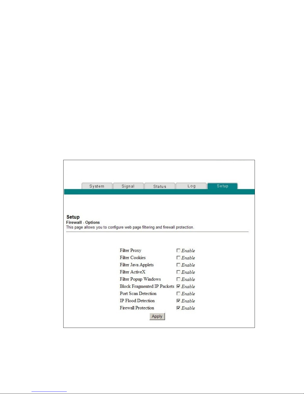
Chapter 5 Security
76 68-4004214-01 Rev D
Configure Security Settings
Configuring Firewall Protection
Use the Setup Firewall - Options page to configure webpage filtering and firewall
protection. This page allows you to enable various firewall protection filters.
Note: If you are not familiar with the advanced settings detailed in this section,
contact your service provider before you attempt to change any of the cable modem
gateway default firewall options settings.
Click Options in the Firewall section of the Setup page to access the Setup Firewall -
Options page.
Setup Firewall - Options Page Example
The following illustration is an example of the Setup Firewall - Options page.
Page 93

Configure Security Settings
68-4004214-01 Rev D 77
Setup Firewall - Options Page Description
This section describes the section headings and fields descriptions of the Setup
Firewall - Options page.
Note: If you make changes in any of the fields in the Setup Firewall - Options page,
click Apply to apply and save your Firewall settings.
The following table provides a description of each field name within the Setup
Firewall - Options page.
Field Name Description
Filter Proxy Enables/disables proxy
Filter Cookies Enables/disables cookie blocking. This feature filters
the unsolicited delivery of cookies to devices from the
Internet to devices in your private local network.
Cookies are computer files that contain personal
information or Web surfing behavior data
Filter Java Applets Enables/disables java applets. This feature helps to
protect the devices in your private network from
irritating or malicious Java applets that are sent,
unsolicited, to devices in your private network from
the Internet. These applets run automatically when
they are received by a PC
Filter ActiveX Enables/disables ActiveX controls. This feature helps
to protect the devices in your private network from
irritating or malicious ActiveX controls that are sent,
unsolicited, to devices in your private network from
the Internet. These ActiveX controls run automatically
when they are received by a PC
Filter Popup
Windows
Enables/disables popup windows. Some commonly
used applications employ popup windows as part of
the application. If you disable popup windows, it may
interfere with some of these applications
Block Fragmented IP
Packets
Enables/disables filtering of fragmented IP packets.
This feature helps protect your private local network
from Internet based denial of service attacks
Port Scan Detection Enables/disables the gateway from responding to
Internet based port scans. This feature is designed to
protect your private local network from Internet
based hackers who attempt to gain unsolicited access
your network by detecting open IP ports on your
gateway
IP Flood Detection Blocks malicious devices that are attempting to flood
devices or networks with illegal broadcast packets.
Also referred to as “broadcast storm”
Page 94

Chapter 5 Security
78 68-4004214-01 Rev D
Field Name Description
Firewall Protection Enables/disables the firewall. When the firewall is
enabled, the firewall will allow most commonly used
applications to automatically open IP ports and pass
data without any special setup or manual port
configuration
Configuring Firewall Event Logging and E-mail Alerts
Use the Setup Firewall - Event Logging page to access the firewall event log and
allows you to enter your e-mail address in order for you to receive e-mail alerts
related to firewall attacks by hackers.
Note: If you are not familiar with the settings detailed in this section, contact your
service provider before you attempt to change any of the cable modem gateway
default firewall event logging settings.
Click Event Logging in the Firewall section of the Setup page to access the Setup
Firewall - Event Logging page.
Setup Firewall - Event Logging Page Example
The following illustration is an example of the Setup Firewall - Event Logging page.
Page 95

Configure Security Settings
68-4004214-01 Rev D 79
Setup Firewall - Event Logging Page Description
The Setup Firewall - Event Logging page shows events captured by the firewall. The
log displays the following items:
Description of the event
Number of events that have occurred
Last occurrence of an event
Target and source addresses
You can configure the system to e-mail log events to the administrator in order for
the administrator to monitor the firewall.
This section describes the section headings and fields descriptions of the Setup
Firewall - Event Logging page.
Field Name Description
Enable Email
Address
Allows you to enter the e-mail address of the person
who monitors the firewall. When an event occurs, it
will be logged and an email will be sent to this
address automatically reporting the event
SMTP Server Name Allows you to enter the mail server name of your
outgoing mail server, or the mail server of your
Internet service provider (ISP)
E-mail Alerts Allows you to enable or disable sending e-mail alerts
Description Describes what event was detected by the gateway's
firewall
Count Displays the number of times the event has been
detected
Last Occurrence Displays the time the last occurrence of this event was
detected
Target Displays the IP address of the device in your private
local network to which the event was directed along
with the IP port number targeted by the event
Source Displays the IP address of the Internet based source of
the event along with the IP port number used by that
device
Page 96

Chapter 5 Security
80 68-4004214-01 Rev D
Function Keys
The following function keys appear on the Setup Firewall - Event Logging page.
Key
Description
Apply Saves the values you enter into the fields without
closing the screen
E-mail Log Allows you to force the system to send an e-mail alert
even if the E-mail Alerts box is left unchecked
Clear Log Allows you to clear all entries in the log
Page 97

68-4004214-01 Rev D 81
Introduction
The safety of our children while they are online is of paramount
importance in today’s open Internet environment. Help ensure your
children's safety on the Internet and enjoy a worry-free online
experience using the parental control features of the cable modem
gateway.
These parental control features allows you to protect your children
from inappropriate online content, control who can communicate with
your child by IM or email, decide how long your children can be
online, and monitor your children's Internet activity.
The WebWizard pages described in this chapter allow you to
configure the parent control feature on the cable modem gateway.
6 Chapter 6
Parental Control
In This Chapter
Configure Parental Control Settings .................................................. 82
Page 98

Chapter 6 Parental Control
82 68-4004214-01 Rev D
Configure Parental Control Settings
Configuring Parental Control
Use the Setup Parental Control - User Setup page to configure parental controls on
the cable modem gateway, and to add or delete the individuals who are authorized
to set parental controls.
Note: If you are not familiar with the settings detailed in this section, contact your
service provider before you attempt to change any of the cable modem gateway
default parental control settings.
Click User Setup in the Parental Control section of the Setup page to access the
Setup Parental Control - User Setup page.
Setup Parental Control - User Setup Page Example
The following illustration is an example of the Setup Parental Control - User Setup
page.
Page 99

Configure Parental Control Settings
68-4004214-01 Rev D 83
Setup Parental Control - User Setup Page Description
This section describes the section headings and fields descriptions of the Setup
Parental Control - User Setup page. This page allows you to set up user profiles.
Each profile can be assigned customized levels of Internet access as defined by the
access rules assigned to that user's profile.
Note: Once you define and enable user profiles, each user must sign-on each time
they wish to access the Internet. The user can sign-on when the pop-up sign-on
screen appears in their Web browser. The user must enter their correct user name
and password in order to gain Internet access.
Important:
Make sure to disable pop-up blockers on your Web browser when using user
profiles.
User names and passwords are case-sensitive.
Field Name Description
Add User Allows you to add a new user profile. Enter the name of
the user and click the Add User button to add the user
to the list
User Settings Allows you to edit a user profile by using the drop-
down menu to edit a user profile. The drop-down menu
allows you to recall the profile to be edited. User names
and passwords are case-sensitive
Make sure to check the Enable box to activate the user
profile. If a profile is not active, that user will not have
any access to the Internet
To remove a user profile, use the drop-down menu to
select the user to be removed and click the Remove
User button
Password Enter the selected user's password in this field. Each
user must enter their User Name and Password each
time they use the Internet. User names and passwords
are case-sensitive
Note: The Gateway will allow each user access to the
Internet, subject to the rules selected on this page for
that user.
Re-Enter Password Re-enter the same password for confirmation of the
password in the previous field
Trusted User Check this box if the currently selected user is to be
designated a trusted user. Trusted users are not subject
to Internet access rules
Page 100

Chapter 6 Parental Control
84 68-4004214-01 Rev D
Field Name Description
Content Rule Select the Content Rule for the current user profile.
Content Rules must first be defined by going to the
Rules Configuration page. You can access the Rule
Configuration page by clicking on the “Basic Rules” link
under the Parental Control section of the Setup page
Time Access Rule Select the Time Access Rule for the current user profile.
Time Access Rules must first be defined by going to the
Time of Day Filter page. You can access the Time of Day
Filter page by clicking on the “Time of Day Rules” link
under the Parental Control section of the Setup page
Session Duration 1440 minutes (factory default)
Enter the amount of time in minutes that the user will
be granted Internet access beginning at the time they
sign on using their User Name and Password
Note: Set the Session Duration to 0 (zero) to prevent
session timeout.
Inactivity time 60 minutes (factory default)
Enter the amount of time during a user session where
there is no Internet access activity, indicating that the
user is no longer online. If the inactivity timer is
triggered, the user session will be closed automatically.
In order to regain Internet access, the user must log in
again with their User Name and Password
Note: Set the Inactivity time value to 0 (zero) to prevent
timeout due to inactivity.
Available Rules Lists available rules. Apply a rule by selecting it from
the list and adding it to the current user profile
Note: Create rules using the Parental Control Setup
pages that follow next.
Current Used Rules Lists rules in use for the current user profile. You can
apply a maximum of four rules to each user profile
Function Keys
The following function keys appear on the Setup Parental Control - User Setup page.
Key Description
Add User Adds and saves a new user to the list of user profiles
Remove User Removes the selected user from the list of user
profiles
Apply Saves all additions, edits, and changes
 Loading...