

Page 1

OL-29161-01
Cisco Model DPC3928/EPC3928
DOCSIS/EuroDOCSIS 3.0 8x4
Wireless Residential Gateway with
Embedded Digital Voice Adapter
Us er Guide
Page 2

Page 3

Please R ead
Important
Read this entire guide. If this guide provides installation or operation instructions,
give particular attention to all safety statements included in this guide.
Page 4

Notices
T rademark Acknowledgm ents
Cisco and the Cisco logo are trademarks or registered trademarks of Cisco and/or its
affiliates in the U.S. and other countries. To view a list of Cisco trademarks, go to this
URL: www.cisco.com/go/trademarks. DOCSIS is a registered trademark of Cable
Television Laboratories, Inc. EuroDOCSIS, EuroPacketCable, and PacketCable are
trademarks of Cable Television Laboratories, Inc. The Wi-Fi Protected Setup mark is
a mark of the Wi-Fi Alliance. Wi-Fi Protected Setup is a trademark of the Wi-Fi
Alliance.
Other third party trademarks mentioned are the property of their respective owners.
The use of the word partner does not imply a partnership rela tionship between
Cisco and any other company. (1110R)
Publication Disclaimer
Cisco Systems, Inc. assumes no responsibility for errors or omissions that may
app ea r in this publication. We reserve the right to change this publication at any
time without notice. This document is not to be construed as conferring by
implication, estoppel, or otherwise any license or right under any copyright or
pat ent , whether or not the use of any information in this document employs an
invention claimed in any existing or later issued patent.
Disclaimer
The maximum performance for wireless is derived from IEEE Standard 802.11
specifications. Actual performance can vary, including lower wireless network
ca pacity, data t hroughput rate, range and coverage. Performance depends on ma ny
factors, conditions and variables, including distance from the access point, volume of
network traffic, building materials and construction, operating system used, mix of
wireless products used, interference and other adverse conditions.
Software and Firmw are Use
The software described in this document is protected by copyright law and
furnished to you under a license agreement. You may only use or copy this software
in accordance with the terms of your license agreement.
The firmware in this equipment is protected by copyright law. You may only use the
firmware in the equipment in which it is provided. Any reproduction or distribution
of this firmware, or any portion of it, without our express written consent is
prohibited.
Page 5

Copyright
© 2014 Cisco Systems, Inc. All rights reserved.
Informa tion in this p ublication is subject to change withou t not ice. No part of this
publication may be reproduced or transmitted in any form, by photocopy,
microfilm, xerography, or a ny other means, or incorp orated into any information
retrieval system, electronic or mechanical, for any purpose, without the express
permission of Cisco Systems, Inc.
Page 6

Page 7

OL-29161-01 iii
Contents
IMPORTANT SAFETY INSTRUCTIONS vii
United States FCC Compli ance xi
CE Compliance xiii
EU Compliance xvi
About This Guide xvii
Introducing the DOCSIS Wireless Residential Voice Gateway 1
Introduction ......................................................................................................................... 2
What's In th e Carto n? .......................................................................................................... 3
Front Panel Description ...................................................................................................... 4
Back Panel Desc ription ....................................................................................................... 6
Installing the DOCSIS Wireless Residential Voice Gateway 9
Installation P reparations ................................................................................................... 10
Install the Wir el ess Res idential Voice Gateway .............................................................. 18
Operation of Front Panel Indicators 21
Initial Power On, Calibratio n, and Registration (AC Power applied) ........................... 22
Normal Op era tio ns (AC Pow er Applied) ....................................................................... 24
Special Co nditio ns ............................................................................................................. 26
Mai nt ai nin g the B attery 27
Location of the Battery ...................................................................................................... 28
Ba t tery Mai nte na nc e ......................................................................................................... 29
Page 8

Contents
iv OL-29161-01
Troubleshootin g the DOCSIS Wireless Residential Voice Gateway31
Fre que nt ly Ask ed Questions ............................................................................................ 32
Common Troubleshooting Issues .................................................................................... 37
Tips for Improv ed Performa nce ....................................................................................... 39
Cus tomer In fo rma tion 41
Page 9
Notice to Installer s
The servici ng instructions in thi s notice ar e for use by qual ified service personnel only. To reduce the
ri sk of electric shock, do not perform any servicing other than tha t contained in the operating
instructions, unless you are qualified to do so.
Notice à l’attention des installateurs de réseaux câblés
Les instructions r elatives a ux inter ventions d ’ entretien, fournies d ans la présente noti ce, s’adr essent
exclusivement au personnel techni que qualifié. Pour r éd uire les ri sques d e chocs électriques, n’ effectuer
aucune interventi on autr e que cell es d écri tes dans le mode d 'emploi et les instructi ons rela tives au
foncti onnement, à moins que vous ne soyez quali fi é pour ce fai re.
Page 10
Mitteilung für CA TV -Techniker
Die in dieser M ittei lung aufgeführten War tungsanweisungen sind ausschließlich für qualifiziertes
Fachper sonal bestimmt. Um d ie Gefahr eines el ektrischen Schlags zu reduzier en, sollten Si e keine
Wartungsarbeiten durchführen, die nicht ausdr ückl ich in d er B edienungsanleitung aufgeführt si nd,
außer Sie si nd z ur Dur chführung solcher Arbeiten qualifiziert.
Aviso a los instaladores de sistem as CA TV
Las instr ucciones d e repara ción contenida s en el presente aviso s on pa ra uso exclusivo por par te d e
pers ona l de ma nteni miento cua lificado. Con el fin de red uci r el r iesgo de d esca rga el éctrica, no realice
ninguna otra operación de reparación distinta a las contenidas en las instrucciones de funcionamiento, a
menos que posea la cualificación necesaria para hacerlo.
20080814_Installer820_Intl
Page 11

IMPORTANT SAFETY INSTRUCTIONS
OL-29161-01 vii
IMPORTANT SAFETY INSTRUCTIONS
1)
Read these ins tr uctions.
4)
Follow all instructions.
5)
Do not use this apparatus near water.
10)
Protect the power cord from being walked on or pinched particularly at plugs,
12)
Use only with the cart, stand, tripod, bracket, or table specified by the
manufacturer, or sold with the apparatus. When a cart is used, use caution when
damaged, liquid has been spilled or objects have fallen into the apparatus, the
apparatus has been exposed to rain or moisture, does not operate normally, or has
WARNING: Avoid e le ct r ic sho ck a nd fire hazard! If this pr oduct connects to coa xial
2) Keep these i nstructi ons.
3) Heed all warnings.
6) Clean only with dr y cloth.
7) Do not block a ny ventilation openings. Install in a ccorda nce with the
ma nufacturer' s instructi ons.
8) Do not install near any heat sources such as radiators, heat registers, stoves, or
other apparatus (including amplifiers) that produce heat.
9) Do not d efeat the safety pur pose of the pol ariz ed or ground ing-type plug. A
polar ized plug ha s two bla des with one wid er than the other. A grounding-type
plug has two blades and a third grounding prong. The wide blade or the third
prong is provided for your safety. If the provided plug does not fit into your
outlet, consult a n electri ci an for r eplacement of the obsol ete outlet.
convenience recepta cl es, and the point w her e they exi t from the a pparatus.
11) Only use atta chments/accessori es specified by the manufactur er.
moving the cart/apparatus combination to avoid injury from tip-over .
13) Unplug this apparatus during lightning storms or when unused for long periods
of time.
14) Refer a ll servicing to qual ified service personnel. Servicing is required when the
apparatus has been damaged in any way, such as a power-suppl y cord or plug is
been d ropped.
P ower Source W arni ng
A label on this product indicates the correct power source for this product. Operate this product only
from an electri ca l outl et w ith the vol tage and frequency i ndicated on the product l abel. If you are
uncertain of the type of power supply to your home or business, consult your service provider or your
local power company.
The AC inlet on the unit must remain accessible and operable at all times.
Ground the Product
cable w iring, be sur e the ca b le syste m is gr ounded (e arthe d). Gr ounding provide s
some protection against voltage surge s and b uilt-up static charges.
Page 12

IMPORTANT SAFETY INSTRUCTIONS
viii OL-29161-01
WARNING: Avoid e lec tr i c shoc k and fir e haz a r d! Do not overload AC p ower/ma ins,
outlets, extension cords, or integral convenience receptacles. For products that require
WARNI NG: Ther e is danger of explosion if the battery is mishandled or incorrectly
P rotect the P roduct from Lightni ng
In add ition to di sconnecti ng the AC power from the wa ll outlet, di sconnect the signal i nputs.
Verify the Power Source from the On/Off Power Light
When the on/off power light is not illumina ted , the a ppar atus may still be connected to the power
source. The li ght may go out when the a pparatus is turned off, r ega r dles s of w hether i t is still plugged
into an AC power source.
Eli mi nate AC Power/Mains Overloads
battery power or other power sources to operate them, refer to the operating
instr uctions f or those p roducts.
Handling Disposable Batteries
This product may contain a rechargeable Lithium-Ion battery to provide stand-by operation in the
event of a n AC pow er fa ilure.
Heed the following warning, follow the Battery Safety and Battery Disposal instructions below, and see
the instr ucti ons la ter in this guide for ha ndli ng, replacing, and disposing of the battery.
replaced. Replace only with the battery recommended by the manufacturer. Do not
disassemble it or attempt to recharge it outside the system. Do not cr ush, p unctur e ,
dispose of in fire, short the external contacts, or expose to water or other liquids.
Dispose of the b atte ry in accordance with local regulations and instr uctions from your
service provider.
Batter y Safety
Insert batteri es cor rectl y. Ther e may be a r isk of explosion if the batteri es ar e incorr ectly inserted .
Do not attempt to recharge ‘disposable’ or ‘non-reusable’ batteri es.
Please follow instructions provided for charging ‘rechargeable’ batteries.
Replace ba tteries with the same or equivalent type that we recommend.
Do not ex pose ba tteries to excessive hea t (such a s sunlight or fir e).
Do not expose batteries to temperatures above 100°C (212°F).
Batter y D i sp o sal
The batteries may contain substances that could be harmful to the environment.
Recycle or dispose of batteries in accordance with the battery manufacturer’s instructions and
local/national disposal and recycling regulations.
The batteries may contain perchlorate, a known hazardous substance, so special handling and
disposal of this product might be necessary. For more information about perchlorate and best
Page 13

IMPORTANT SAFETY INSTRUCTIONS
OL-29161-01 ix
ma nagement practices for perchlor ate-containi ng substa nce, see
WARNING: Avoid e le ct r ic sho ck a nd fire hazard! Do not ex pose this product to
WARNING: Avoid ele ctr ic shock a nd f ire ha z a r d! U np lug thi s pr oduct befor e cl e a ning .
WARNING: Avoid e le ct r ic sho ck a nd fire hazard! Neve r p ush ob jects through the
WARNING: Avoid e lec tr i c shoc k! Do not open the cover of this p r oduct. Op e ning or
www.dtsc.ca.gov/hazardouswaste/perchlorate
Provide V entilation and Select a Location
Remove all pa ckaging ma ter ial befor e a pplying pow er to the product.
Do not place this apparatus on a bed, sofa, rug, or similar surface.
Do not place this apparatus on an unstable surface.
Do not insta ll this a ppar atus in an enclosure, such as a bookcase or r ack, unless the installation
provides proper ventilation.
Do not place entertainment devices (such as VCRs or DVDs), lamps, books, vases with liquids, or
other objects on top of this product.
Do not block ventilation openings.
Opera ting E nvi ronm ent
This product is designed for operation indoors with a temperature range from 32° to 104° F (0° to 40°C).
Each product should have adequate spacing on all sides so that the cooling air vents on the chassis are
not blocked.
P rotect from E xpos ure to Moisture and Fore ign O bject s
dripping or splashing liq uids, rain, or moisture. Objects filled with liquids, such as
vases, should not be placed on this apparatus.
Do not use a liquid cleaner or an aerosol cleaner. Do not use a magnetic/static cleaning
device (dust re mover ) to clea n this product.
openings in this p roduct. Foreign objects can cause electrical shorts that can result in
electric shock or fire.
Service Warnin gs
removing the cover may e xp ose you to dangerous voltage s. If you ope n the cover, your
warranty will be void. This product contains no user-serviceable parts.
Check Product Safety
Upon completion of any service or r epair s to this product, the ser vi ce technician must perfor m safety
checks to d etermine that this product is in proper operating cond ition.
P rotect the P roduct W hen Movi ng It
Always disconnect the pow er source when moving the a ppar atus or connecti ng or disconnecting
cabl es.
Page 14

IMPORTANT SAFETY INSTRUCTIONS
x OL-29161-01
T el ephone E quipm e nt Not ice
CAUTI ON: To r educe the r isk of fir e, us e onl y No. 26 AWG or la r ger
When using your tel ephone equipment, bas ic sa fety precautions should a lways be followed to reduce
the risk of fire, electric stock and injury to persons, including the following:
1. Do not use this product near water, for example, near a bath tub, wash bowl, kitchen sink or laundry
tub, i n a wet basement or near a swimming pool.
2. Avoid using a telephone (other than a cord less type) during an electr ical stor m. There may be a
remote risk of electric shock from lightning.
3. Do not use the telephone to repor t a gas l eak in the vicini ty of the lea k.
telecommunica tion line cord.
SAVE THESE I NSTRU CTI ONS
Page 15

United Sta te s FCC Complianc e
OL-29161-01 xi
United S tates FCC Compliance
This device has been tested and found to comply with the limits for a Class B digital device,
pursuant to part 15 of the FCC Rules. These limits are designed to provide reasonable
protection against such interference in a residential installation. This equipment generates,
uses, and can radiate radio frequency energy. If not installed and used in accordance with the
instructions, it may cause harmful interference to radio communications. However, there is
no guarantee that interference will not occur in a particular installation. If this equipment
does cause harmful interference to radio or television reception, which can be determined by
turning the equipment OFF and ON, the user is encouraged to try to correct the interference
by one or more of the followin g measures:
Reorient or relocate the receiving antenna.
Increase the separation between the equipment and receiver.
Connect the equipment into an outlet on a circuit different from that to which the
receiver is connected.
Consult the service provider or an experienced radio/television technician for help.
An y changes or modifications not expressly approved by Cisco Systems, Inc. , could void the
user's authority to operate the equipment.
The information shown in the FCC Declaration of Conformity paragraph below is a
requirement of the FCC and is intended to supply you with information regarding the FCC
approval of this device. The phone numbers listed are for FCC-related questions only and not
intended for questions regarding the connection or operation for this device. Please contact your
service provider for any questions you may have regarding the operation or installation of this device.
De cla ration of Conform it y
This device complies with Part 15 of FCC
Rules. Operation is subject to the following
two condition s: 1) the dev ice m ay not cause
harmful interference, and 2) the device must
accept any interference received, including
interference that may cause undesired
operation.
Canada EMI R egulation
This Class B digital apparatus complies with Canadian ICES-003.
Cet appareil numérique de la class B est conforme à la norme NMB-003 du Canada.
DOCSIS Wireless Residential Voice
Gateway
Model(s): DPC3928 EPC3928
Manufactured by: Cisco Systems, Inc.
170 West Tasman Drive
San Jose, California 95134 USA
Page 16

United Sta te s FCC Complianc e
x ii OL-29161-01
RF E x posure S tatements
Note: This transmitter must not be co-located or operated in conjunction with any other
antenna or transmitter. This equipment should be installed and operated with a minimum
distance of 7.9 inches (20 cm) between the radiator and your body. For products available in
the USA/Canada market, only channels 1-11 can be operated. The selection of other channels
is not possible.
US
This system has been evaluated for RF exposure for humans in reference to ANSI C 95.1
(American National Standards Institute) limits. The evaluation was based in accordance with
FCC OET Bulletin 65C rev 01.01 in compliance with Part 2.1091 and Part 15.27. The minimum
separation distance from the antenna to general bystander is 7.9 inches (20 cm) to maintain
compliance.
Canada
This system has been evaluated for RF exposure for humans in reference to Canada Health
Code 6 (2009) limits. The evaluation was based on evaluation per RSS-102 Rev 4. The
minimum separation distance from the antenna to general bystander is 7.9 inches (20 cm) to
maintain compliance.
Page 17
CE Compliance
OL-29161-01 xiii
CE Compliance
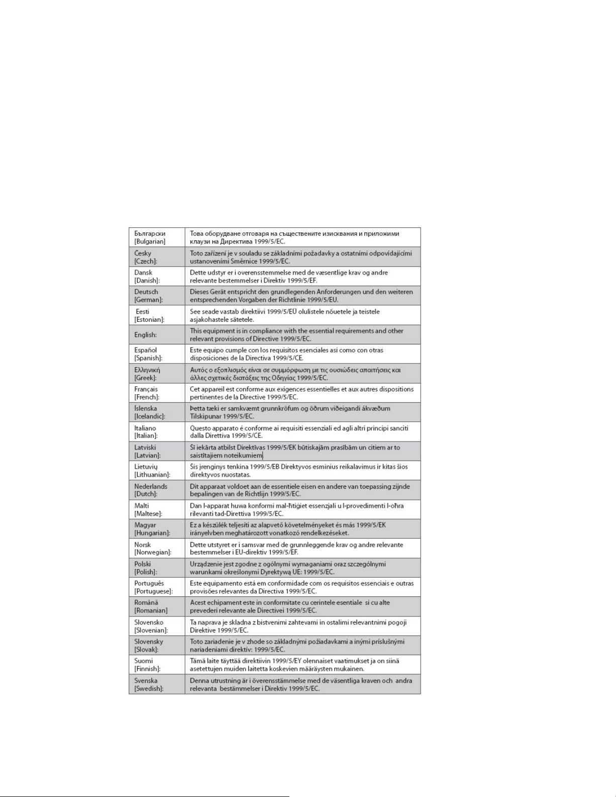
Declaration of Conformity with Regard to the EU Directive 1999/5/E C (R&TTE Directive)
This declaration is only valid for configurations (combinations of software, firmware and
hardware) supported or provided by Cisco Systems for use within the EU. The use of
software or firmware not supported or provided by Cisco Systems may result in the
equipment no longer being compliant with the regulatory requirements.
Page 18

CE Compliance
x iv OL-29161-01
Note: The full declaration of conformity for this product can be found at
http: //www.cisco.com/ we b/co nsumer/ sup port/comp lia nce_info. htm l.
The following standards were applied during the assessment of the product against the
requirements of the Directive 1999/5/EC:
Radio: EN 300 328
EMC: EN 301 489-1 and EN 301 489-17
Safety: EN 60950 and EN 50385
The CE mark and class-2 identifier are affixed to the product and its packaging. This product
conforms to the following European directives:
National Restrictions
This product is for in door use only.
France
For 2.4 GHz, the output power is restricted to 10 mW EIRP when the product is used
outdoors in the band 2454 - 2483.5 MHz. There are no restrictions when used in other parts of
the 2.4 GHz band. Check http://www.arcep.fr/ for more details.
-1999/5/EC
Pour la bande 2,4 GHz, la puissance est limitée à 10 mW en p.i.r.e. pour les équipements
utilisés en extérieur dans la bande 2454 - 2483,5 MHz. Il n'y a pas de restrictions pour des
utilisations dans d'autres parties de la bande 2,4 GHz. Consultez http://www.arcep.fr/ pour
de plus amples détails.
Italy
This product meets the National Radio Interface and the requirements specified in the
National Frequency Allocation Table for Italy. Unless this wireless LAN product is operating
within the boundaries of the owner's property, its use requires a “general authorization.”
Please check http://www.comuni cazioni.it/i t/ for more details.
Questo prodotto è conforme alla specifiche di Interfaccia Radio Nazionali e rispetta il Piano
Nazionale di ripartizione delle frequenze in Italia. Se non viene installato all 'interno del
proprio fondo, l'utilizzo di prodotti Wireless LAN richiede una “Autorizzazione Generale”.
Consultare http://www.comunicazi oni.it/i t/ per maggiori dettagli.
Page 19

CE Compliance
OL-29161-01 xv
Antennas
Latvia
The outdoor usage of the 2.4 GHz band requires an authorization from the Electronic
Communications Office. Please check http://www.esd.lv for more details.
2,4 GHz frekvenču joslas izmantošanai ārpus telpām nepieciešama atļauja no Elektronisko
sakaru direkcijas. Vairāk informācijas: http://www.esd.lv.
Note: The regulatory limits for maximum output power are specified in EIRP. The EIRP level
of a dev ice can b e calculated by adding the gain of the antenna used (specified in dBi) to the
output power available at the connector (specified in dBm).
Use only the antenna supplied with the product.
Page 20

EU Compliance
x vi OL-29161-01
EU Compliance
This device complies with Commission Regulations (EU) No. 1275/2008 and
801/2013. For more information on the energy consumption of this product, go
to www.cisco.com/go/cpe-eu-lot26-results
.
Page 21

About This Guide
OL-29161-01 xvii
About This G uide
Introduction
Welcome. This guide provides instruct ions and recommendat ions for p la cing,
installing, configuring, operat ing, maintaining, a nd troubleshooting the DPC3 9 28
(with or without a battery) and EPC3928 DOCSIS Wireless Residential Voice
Gateways.
Purpose
This guide covers the following product models:
DPC3928 DOCSIS Wireless Residential Voice Gateway (with or without a
battery)
EPC3928 DOCSIS Wireless Residentia l Voice Gateway
All features described in this guide are standard to these models of residential
gatewa ys unless otherwise noted. For the purpose of this guide, whenever a feature
or option applies to only a specific model, the model number is specified. If a model
number is not specified, then the feature or option applies to both of the models.
Audience
This guide is written for the home subscriber.
Document Version
This is the second formal release of this document . In addition to minor text and
graphic changes, cha nges ha ve been made to add information about the DPC3 928
with battery option and to provide information about compliance with Commission
Regulations (EU) No. 1275/2008 and 801/2013.
Page 22

Page 23

OL-29161-01 1
residential gateway and the benefits it offers. This chapter also lists the
1 Chapter 1
Int r oduci ng the D OC SI S
Gateway
Back Panel Desc ription ........................................................................6
Wireless Resid ential Vo ice
Introduction
This chapter provides an overview of residential gateway features,
indica tors, and connectors to help you become familiar wit h the
accessories and equipment that are provided with the residential
gateway so that you can verify that you received all of these items.
In Thi s Cha pte r
Introduction ..........................................................................................2
What's In th e Carto n? ...........................................................................3
Front Panel Description .......................................................................4
Page 24

Chapter 1 Introducing the DOCSIS Wireless Residential Voice Gateway
2 OL-29161-01
Introduction
Your new Cisco® Model DPC3928 DOCSIS® 3.0 or EPC3928 EuroDOCSIS™ Wireless
Residential Gateway with Embedded Digital Voice Adapter is a cable modem that
meets industry standards for high-speed data connectivity along with reliable digital
telephone service. The DPC39 28 and EPC3928 residential ga teway delivers data,
voice and wired (Ethernet) or wireless gateway capabilities to connect a variety of
devices in the home or small office and support high-speed data access and costeffective voice services, all in one device.
This guide provides procedures and recommendations for placing, installing,
configuring, operating, and troubleshooting your DPC3928 and EPC3928 residential
gateway for high-speed Internet and digital telephone service for your home or
office. Refer to the appropriate section in this guide for the specific information you
need for your situation. Contact your service provider for more information about
subscribing to these services.
Your new residential gateway offers the following outstanding benefits and features:
Compliant with DOCSIS and EuroDOCSIS 3.0, 2.0, and 1.x standards along with
PacketCable™ and EuroPacketCable™ specifications to deliver high-end
performance and reliability
High performance broa dba nd Internet connectivity to energize your online
experience
Two-line embedded digital voice adapter for wired telephony service
Four 1000/100/10BASE-T Ethernet ports to provide wired connectivity
802.11n Wireless Access Point
User configurable Parental Control blocks a ccess to undesirable Internet sites
Advanced firewall technology deters hackers and protects the home network
from unauthoriz ed access
Attractive compact design that allows for vertical, horizontal, or wall-mounted
operation
Color-coded interface ports and corresponding cables simplify installation and
setup
DOCSIS-5 compliant LED labeling and behavior provides a user and technician
friendly method to check operational status and act as a troubleshooting tool
A llows automatic software upgrades by your service provider
Page 25
What's In the Carton?
OL-29161-01 3
What's In the Carton?
When you receive your residential gateway, you should check the equipment and
accessories to verify tha t each item is in the carton and that each item is undamaged.
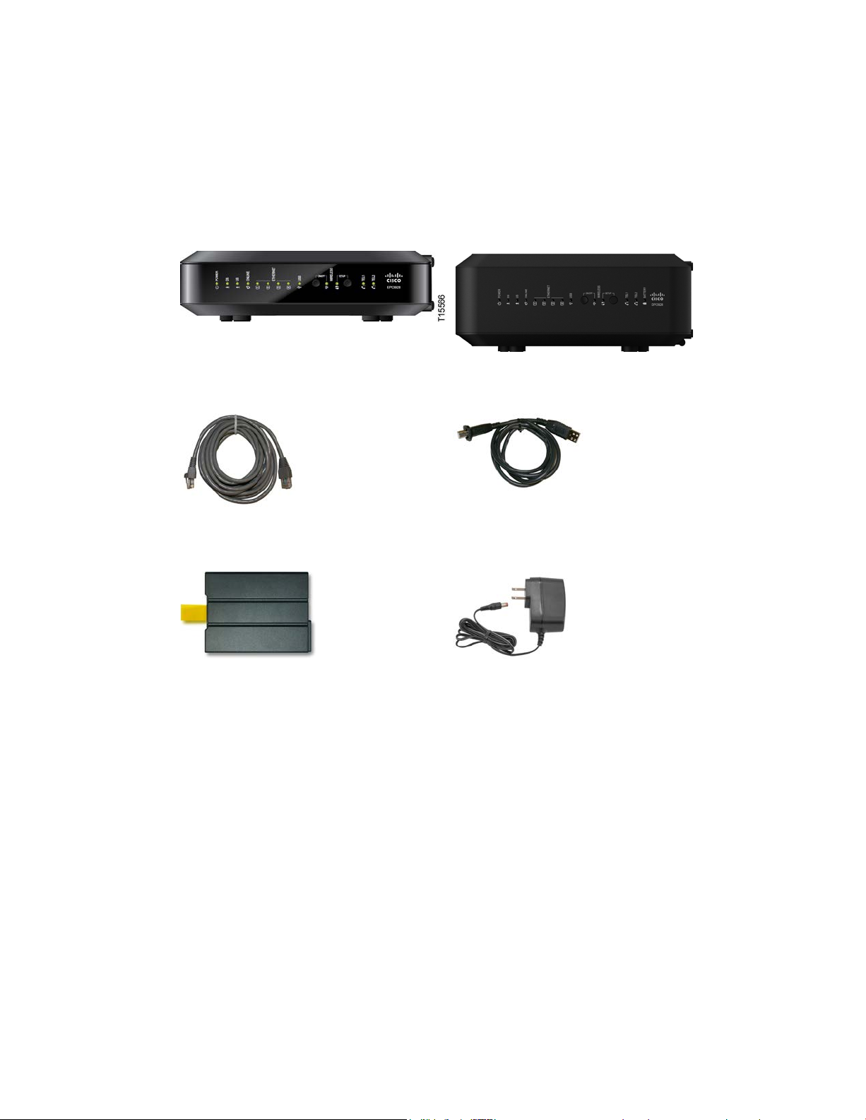
The carton contains the following items:
One DPC3928 or EPC3928 DOCSIS
Wireless Residential Voice Gateway
(no battery)
One Et hernet cable ( May not be
provided with all products.)
One Lithium Ion cartridge bat tery
(Image may vary from product. May
not be provided with all products.)
If any of these items are missing or damaged, please contact your service provider
for assistance.
Or one DPC3928 (with battery)
One USB cable (Image may vary from
actual product. May not be provided
with all products.)
One power ada pter (models requiring
external power supply)
Notes:
You need an optional cable signal splitter and additional standard RF coaxial
cables if you want to connect a VCR, a Digital Home Communications Terminal
(DHCT) or a set-top converter, or a TV to the same cable connection as your
residential ga teway.
If your product supports telephone service, cables and other equipment needed
for telephone service must be purchased separately. Contact your service
provider to inquire about the equipment and cables you need for telephone
service.
Page 26

Chapter 1 Introducing the DOCSIS Wireless Residential Voice Gateway
4 OL-29161-01
Front Panel Descriptio n
The front panel of your residential gateway provides LED status indicators that
indicate how well and at what state your residential gateway is operating. See
Operation of Front Panel Indicators (on page 21), for more information on front
panel LED stat us indicator functions.
EPC3928 (model shown without battery backup capability)
DPC3928 (model shown with battery backup capability)
1 POWER—ON, power is applied to the residential gateway
2 DS—ON, the residential gateway is receiving data from the cable network
3 US—ON, the residential gateway is sending data to the cable network
4 ONLINE—ON, the residential gateway is registered on the network and fully
operational
5 ETHERNET 1 - 4—ON, a device is connected to one of the Ethernet ports.
BLINKING indicates that data is being transferred over the Ethernet connection
6 USB—ON, a device is connected to the USB port. BLINKING indicates that data
is being transferred over the USB connection
Page 27

Front Panel Description
OL-29161-01 5
7 WIRELESS ON/OFF (Optional)—Press this button to activate and turn on the
Wireless feature. This feature allows users to transfer data over the wireless
connect ion. When the WIRELESS indicator is ON, it indicates that the Wireless
Access Point is operational. BLINKING indicates tha t data is being transferred
over the wireless connection. OFF indica tes that the Wireless feature has been
disabled.
8 WIRELESS SETUP—Press this button to activate the Wireless Setup feature.
This feature allows users to add new Wireless Protected Setup (WPS) compliant
wireless clients to the home network. When the SETUP indicator is OFF (normal
condition), it indicates that the wireless setup is not active. BLINKING indicates
the user has activated wireless setup to add new wireless clients on the wireless
network.
9 TEL1—ON indicates telephony service is enabled. Blinks when line 1 is in use.
OFF indicates that phone service for TEL 1 is not enabled
10 TEL2—ON indicates telephony service is enabled. Blinks when line 2 is in use.
OFF indicates that phone service for TEL 2 is not enabled
11 BATTERY (optional model only)—ON indicates the battery is charged. Blinking
indicates the battery charge is low. OFF indicates the unit is operating from
battery power, the battery charge is depleted, or the battery is defective or
missing
Notes:
After the residential gateway is successfully registered on the network, the
POWER, DS, US, and ONLINE LEDs illuminate continuously to indicate that the
residential gateway is active and fully operational.
The high-speed data operation is disabled when operating on battery power;
only the telephone service (if available on this model) is active when operating
on battery power.
LEDs may behave differently when t he resident ia l gateway is running on battery
power (without AC power). Most LEDs a re disabled if t he unit is operat ing on
battery power. In this mode, the POWER LED blinks to indicate that the unit is
operating under ba ttery power.
The res idential gateway should only run on battery power when AC power has
failed. If the POWER LED indica tes that the unit is running on battery power,
but the AC power has not failed, verify that the power cord is plugged into a
working AC outlet.
Page 28

Chapter 1 Introducing the DOCSIS Wireless Residential Voice Gateway
6 OL-29161-01
Back Panel D escriptio n
The following illustration identifies the back panel components on the DPC3 928 a nd
EPC3928 residential gateways. Descriptions for each component follow the
illustration.
The following illustration shows the back panel of the DPC3928 with battery backup
capability.
Important: Do not connect your PC to both the Ethernet and USB ports at the same
time. Your residential gateway will not function properly if both the Ethernet and
USB ports are connected to your PC at the same time.
1 ON/OFF SWITCH (Provided only on products that carry the CE mark)—
Allows you to turn off of the residential gateway without removing the power
cord. Turning the residential ga t eway off using this switch ensures that the unit
is consuming no energy.
Page 29

Back Panel Descript ion
OL-29161-01 7
2 POWER—Connects the resident ial gateway to the AC power adapter that is
instructed to do so by your service provider. Doing so may cause you to lose
provided with your residential gateway
Important: Use only the power supply provided with your residential gateway.
3 TELEPHONE 1 and 2—RJ-11 telephone ports connect to home telephone wiring
to conventional telephones or fax machines. (P roducts shipping in North
America supp ort lines 1 and 2 on port 1 when us ed wit h a two-line phone.)
4 USB (Optional for some models)—Connects to selected devices. For models that
support USB, the default is one USB port.
5 ETHERNET—Four RJ-45 Ethernet ports connect to the Ethernet port on your PC
or your home network
6 RESET—A momentary pressing (1-2 seconds) of this button performs a software
reset the device. Pressing and holding the button for more than ten seconds first
causes a reset-to-factory-default of all settings and then performs a software reset
of the device
CAUTION:
The RESET button is for maintenance purposes only. Do not use unless
any settings you have selected.
7 MAC ADDRESS LABEL—Displays t he CM, EMTA, and WAN MA C addresses
for the residential gateway
8 CABLE—F-connector connects to an active cable signal from your service
provider
Page 30

Page 31

OL-29161-01 9
2 Chapter 2
Installing the DOCSIS Wireless
Residential Voice Gateway
Install the Wireless Reside ntial Voice Gateway ...............................18
Introduction
This chapter describes how to properly install the residential gateway
and connect the residential gateway to a computer and other devices.
In Thi s Cha pte r
Installation P reparations ....................................................................10
Page 32

Chapter 2 Inst all ing the DOCS IS Wireless Residen t ial Voice Gateway
10 OL-29161-01
Installati on P reparatio ns
Before installing the residential gateway, make sure that your system meets or
exceeds the requirements listed in this section. Also, make s ure that you have
prepared your home and home devices as described in this section.
What Are the System Requirements for Internet Service?
To ensure that your residential gateway operates efficiently for high-speed Internet
service, you must have a n Internet-capable PC, Mac, or Internet a ppliance equipped
with an Ethernet port or Wi-Fi capability.
Note: You will also need an active ca ble input line and a n Internet connection.
What Are the Requirements for T elephone S ervice?
If you intend to use the residential gateway for digital telephone service, verify that
your home meets or exceeds a ll of the following requirements.
Max imum Number of Tele phone s
The RJ-11 telephone-style connectors on the residential gateway can each provide
telephone service to multiple telephones, fax machines, and analog modems.
The maximum number of telephone devices connected to each RJ-11 port is limited
by t he tota l Ringing Load of the telephone devices tha t are connected. Many
telephone devices a re marked with a Ringer Equivalent Number (REN). Each
telephone p ort on the residential gateway can support up to a 5 REN load.
The sum of the REN load on all of the telephone devices attached to each port must
not exceed 5 REN.
Telephone Device Types
You can use telephone devices that are not labeled with a REN number, but the
maximum number of attached telephone devices cannot be accurately calculated.
With telephone devices that are not la beled, each device should be connected and
the ring signal should be tested before adding more devices. If too many telephone
devices are atta ched and the ring signal can no longer be heard, telephone devices
should be removed until the ring signal works properly.
Telephones, fax machines, and other telephone devices use the center 2 pins of the
RJ-11 connectors to connect to your primary service. The outer 2 pins of the
connector may be provisioned to provide a second telephone line. Contact your
service provider for more information.
Page 33

Insta llation Pre para tions
OL-29161-01 11
Dialing Re quire ment s
All of your telephones should be set to use Dual-Tone Multi-Frequency (DTMF)
dialing. Pulse dialing may not be supported by your local service provider.
T e le phone Wiring Requirement s
The residential gateway supports connecting to the interior telephone wiring as well
as connecting direct ly to a telephone or fax machine. The maximu m dista nce from
the unit to the most distant telephone device must not exceed 1000 feet (300 meters).
Use 26-gauge twisted-pa ir, or la rger, telephone wiring.
Important: Connection to an existing or a new permanently insta lled home
telephone wiring network should be completed by a qualified installer or at the
direction of your telephone service provider.
What T ypes of Service Accounts Do I Need?
Depending upon the features that your service provider offers, you may need to
establish one or both of the following account s:
A high-speed Internet access account, if your residential gateway supports an
Internet connection
An account for telephone service, if your residential gateway supports digital
telephone service
Refer to one of the following topics to learn more about the types of service accounts
that you may need to establish.
High-Speed Internet Access Account
If you do not have a high-speed Internet access account, your service provider will
set up your account and become your Internet service provider (ISP). Internet access
enables you to send and receive email, access the World Wide Web, and receive
other Internet services.
You will need to give your service provider information about the residential
gatewa y to use the high-speed Internet feature that this product offers. See
Information Your Service Provider Needs (on page 12) to learn how to locate the
information your service provider needs to establish a high-speed Internet access
account for the residential gateway
If you ha ve an existing high-speed Internet access account, you will need to give
your service provider the serial number and MAC address of the residential gateway
to use the high-speed Internet feature that this product offers. See Information Your
Service Provider Needs (on page 12) to learn how to locate this information.
Page 34

Chapter 2 Inst all ing the DOCS IS Wireless Residen t ial Voice Gateway
12 OL-29161-01
Inform ation Your Servic e Prov ider N eeds
You will need to give your service provider the following information, which is
printed on the bar code label attached to the device:
The Serial Number (S/N) of the residential ga teway. The serial number consists
of a series of nine digits.
The Media Access Control (CM MAC) address of the residential gateway. The
CM MA C address consists of a series of 12 alphanumeric characters.
The Media Access Control (MAC) a ddress of the residentia l ga teway media
terminal adapter (MTA MAC). The MTA MAC address consists of a series of 12
alphanumeric chara cters.
The following illustration shows a typical bar coded label; the image may vary from
the label on the actual product.
Write down these numbers in the spaces provided:
Serial Number _______________________
CM MAC Address ________________________
MTA MAC Address ______________________ __
I Already Have a High-Speed Internet Access Account
Teleph o n e Ser vi ce
You will need to establish a telephone account with your local service provider to
use your residential ga teway for telephone service.
When you contact your service provider, you may be able to transfer your existing
telephone numbers. If not, then your cable telephony service provider will assign a
new telephone number to enable your voice service(s). Discuss these options with
your telephony service provider.
Page 35

Insta llation Pre para tions
OL-29161-01 13
Where Is the Best Location for My W ireless Residential Voice Gateway?
The ideal location for your residential gateway is where it has access to outlets and
other devices. Think about the layout of your home or office, and consult with your
service provider to select the best location for your residential gateway. Read this
user guide thoroughly before you decide where to place your residential gateway.
Consider these recommendations:
Choose a location close to your computer if you will also use the residential
gateway for high-speed Internet service.
Choose a loca tion that is near a n existing RF coaxial connection to eliminate the
need for an additional RF coaxial outlet.
Choose a location that is relatively protected from accidental disturba nce or
harm, such as a closet, basement, or other protected a rea.
Choose a location so that there is plenty of room to guide the cables away from
the residential gateway without straining or crimping them.
Choose a location that allows adequate ventilation around the residential
gateway.
Choose a location for the residential gateway that is adjacent to your telephone
equipment if you pla n on connecting your phone directly to the residential
gateway.
Note: If you are using the residentia l gateway to provide service to several
telephones, a professional installer can connect the residential gateway to your
existing home telep hone wiring.
Install the Battery
Your residential gateway may include one rechargeable Lithium-Ion battery to
provide stand-by operation in the event of an AC power failure. We recommend that
you install the battery before mounting the residential gateway to a wall (if you
decide to do so) and before installing the residential gateway in your home.
It is possible to use the residential gateway without the battery. However, if you
choose to operate the residential gateway without a battery, you will not have
telephone service during a power outage.
For information on batt ery ma intenance, see Maintaining the Battery (on pa ge 27).
Inst a lling t he Ba t t e ry
Installing the battery requires no tools. Follow these instructions to install the
battery.
Page 36

Chapter 2 Inst all ing the DOCS IS Wireless Residen t ial Voice Gateway
14 OL-29161-01
WARNING:
Fully charged high-capacity rechargeable batteries should be handled with
care. Replace only with the battery recommended by the manufacturer. Do not
disassemble it or attempt to recharge the battery outside the system. Do not
crush, puncture, dispose of in a fire, short the external contacts, or expose to
high temperature or immerse in water or other liquids. Dispose of the battery
in accordance with local regulatio ns and instructions from y our service
provider.
1 Turn the residential gateway so that you are facing the side with the battery
compartment.
2 Gently release the latch to open the battery cover and gain access to the battery
compartment.
3 Insert the battery into the battery compartment. Do not force the battery into the
compartment, but be sure to press the battery all the way in until it seats fully.
Important: Take care to position the battery correctly. Insert the battery only as
shown in the following illustration.
4 Close the battery compartment door.
Important: After you install the residential gateway and plug it into an AC
electrical outlet as described in Install the Wireless Residential Voice Gateway
(on page 18), it can take as long as 24 hours for the battery to charge fully.
However, you can begin using your high-speed Internet a nd telephone service
immediately after installation. See Normal Operations (AC Power Applied) (on
pa ge 24) for inf orma tion on how the LEDs on t he front of the residential gateway
indicate the state of the battery charge.
How Do I Mount t he Wireless Residential Vo ice Gateway on a Wall? (Optional)
Your residential gateway may include mounting holes so that, if you wish, you can
mount the residential gateway to a wall. This section describes how to mount the
residential gateway to a wall, and includes a list of the equipment that you will need
along with suggestions for choosing a n a ppropria te place to mount the residential
gateway.
Page 37

Insta llation Pre para tions
OL-29161-01 15
Important: If you have not already done so, insert the battery in the residentia l
gatewa y before you mount the residential gateway on a wall (if desired) or before
you install the residential gateway in your home. For assistance inserting the battery
in the residential gatewa y, see Install the Battery (on page 13).
Se le c t an Appropriat e P la c e t o Mount t he Wirele s s Re s ide nt ia l V oic e G a t e way
You may mount the residential gateway to a wall that is made of cement, wood, or
drywall. When choosing an a ppropria te mounting p la ce, refer to the following
recommendations:
Ensure that the mou nting location is free of obstructions on all sides, and the
cables should be able to easily reach the residential gateway without strain.
Leave sufficient clearance between the bottom of the residential gateway and any
flooring or shelving underneath to allow access to cabling.
Allow enough slack in all cables so that the residential gateway can be removed
for any required maintenance without disconnecting the cables.
Choose a location that allows adequate ventilation around the residential
gateway.
Equipment Ne e de d
Verify that you ha ve the following it ems that you will need to mount the residential
gateway:
Two wall anchors for #8 x 1-inch screws
Two #8 x 1-inch p an head sheet meta l screws
Drill with a 3/16-in. wood or masonry bit, as appropriate for the wall
composition
A copy of the wall-mounting illustrations shown on the following pages
Page 38

Chapter 2 Inst all ing the DOCS IS Wireless Residen t ial Voice Gateway
16 OL-29161-01
Position the Wireless Residential Voice Gateway
Use the following illustrations to guide you in positioning the residential gateway on
the wall.
Locat ion a nd Dimens ions of t he Wa ll-Mounting Slots
The following illustration shows the location and dimensions of the wall-mounting
slots on the bottom of the residential gateway. Use this illustration as a guide for
mounting the residential gateway to the wall.
Page 39

Insta llation Pre para tions
OL-29161-01 17
Note: Image not to scale.
Mounting the Wire le s s Re s ide nt ia l V oic e Gate w a y on a Wall
1 Using a drill with a 3/16-inch bit, drill two holes at the same height and 4 inches
apa rt.
Note: The p receding gra phic illu strates t he locat ion of the mounting holes on the
back of the residential gateway.
2 Are you mounting the residential gateway into a drywall or concrete surface
where a wooden stud is available?
If yes, go to step 3.
If no, drive the anchor bolt s into the wa ll, and install the mounting screws
into the anchor bolts; leave a gap of about 1/4-inch between the screw head
and the wall. Then, go to step 4.
3 Install the mounting screws into the wall; leave a gap of about 1/4-inch between
the screw head and t he wall. Then, go to step 4.
4 Verify that no cables or wires are connected to the residentia l gateway.
5 Lift the residential gateway into position. Slip the large end of both mounting
slots (located in the back of the residentia l gateway) over the mounting screws,
and t hen slide the residentia l gateway down until the narrow end of the keyhole
slot contacts the screw shaft.
Important: Verify that the mounting screws securely support the residential
gatewa y before you release the unit.
Page 40

Chapter 2 Installing the DOCSIS Wireless Residen t ial Voice Gateway
18 OL-29161-01
Install the Wireless R esidenti al V oice Gatew ay
This section describes how t o connect your residential gateway to support the
services that the residential gateway offers.
Important: If you have not already done so, insert the battery in the residentia l
gatewa y before you mount the residential gateway on a wall (if desired) or before
you install the residential gateway in your home. For assistance inserting the battery
in the residential gatewa y, see Install the Battery (on page 13).
Connect Devices to the Wireless Residential Voice Gateway
The following illustration shows all of the possible connections that can be made to
your residential gateway for various services. Although your model may not
support all of the services pictured, you can determine which services your model
supports by referring to the Benefits and Features list in Introduction (on page 2).
Notes:
Professional installation may be available. Contact your local service provider for
further assistance.
D evice image varies according to model.
Page 41

Install the Wireless Residential Voice Gateway
OL-29161-01 19
Connect the Wi reless Residential Voice Gateway
WARNING:
The following ins talla tion procedure ensures proper setup and configuration for the
residential ga teway.
1 Choose an appropriate and safe location to install the residential gateway (close
to a power source, an active cable connection, and your PC-if using high-speed
Internet). For assistance, go to Where Is the Best Location for My Wireless
Residential Voice Gateway? (on page 13).
To avoid personal injury, follow the installation instructions in the exact
order shown.
Wiring and connections must be properly insulated to prevent electrical
shock.
Disconnect power from the residential gateway before attempting to
connect to any device.
2 Power off your PC and other networking device; then, unplug them from the
power source.
3 Connect the active RF coaxia l cable from your service provider to the coa x
connector la beled CABLE on the back of the residential gateway.
Note: To connect a TV, DHCT, set-top, or VCR from the same cable connection,
you will need to install a cable signal splitter (not included). Always check with
your service provider before using a splitter as a splitter may degrade the signal.
4 Connect your PC to t he residentia l gateway using eit her of the following
connect ions:
Ethernet Connection: Locate the yellow Ethernet cable, connect one end of
the Et hernet cable to the Et hernet port on your PC, a nd connect the other end
to the yellow ETHERNET port on the back of the residential gateway.
Note: To install more Et hernet devices than ports provided on the residential
gatewa y, use an external multi-port Ethernet switch(s).
Wireless: Make sure that your wireless device is powered up. You will need
to associate your wireless device with the wireless residential gateway once
the residential gateway is operational. Follow the directions provided for
your wireless device for associating with a wireless access point. If the
residential gateway has a WIRELESS ON/OFF button, make sure that
WIRELESS is enabled by confirming that the ON/OFF indicator is ON. If the
indicator is OFF, press the ON/OFF button to enable the WIRELESS feature.
More information about the factory default configuration of your wireless
residential gateway can be found later in this guide in Configure Wireless
Settings.
Page 42

Chapter 2 Inst all ing the DOCS IS Wireless Residen t ial Voice Gateway
20 OL-29161-01
5 Locate the AC power cord provided with your residentia l ga teway. Insert one
end of t he p ower cord into the AC connector on the back of the residential
gatewa y. Then, plug the AC power cord into an AC outlet to power-up the
residential ga teway. The residential gateway will perform an automatic search to
locate a nd sign on to the broadband data network. This p rocess may take up to 25 minutes. The residential gateway will be ready for use when the POWER, DS,
US and ONLINE LEDs on the front panel of the residential gatewa y stop
blinking and rema in on continuously.
6 Plug in and power on your PC and ot her home network devices. The LINK LED
on the residential gateway corresponding to the connected devices should be on
or blinking.
7 Once your residential gateway is online, most Internet devices will have
immediate Internet access.
Note: If your PC does not have Internet access, refer to How Do I Configure
TC P/IP Protocol? (on page 32) for information on how to configure your PC for
TCP/IP. For Internet devices other than PCs, refer to the DHCP or IP Address
configuration section of t he User Guide or O perations Ma nual for those devices.
Page 43

OL-29161-01 21
3 Chapter 3
Oper ation of Front Panel
Indicators
Special Co nditio ns ..............................................................................26
Introduction
This chapter des cribes the behavior of the front panel indicators when
the residential gateway is first powered up, during normal operations,
and in special conditions.
In Thi s Cha pte r
Initial Power On, Calibration, and Registration (AC Power
applied) ...............................................................................................22
Normal Op era tio ns (AC Pow er Applied) ........................................24
Page 44

Chapter 3 Operation of Front Panel Indicators
22 OL-29161-01
Initial Power On, Calibration, and Registrat ion (AC
Registration
Front Panel
Self
Downstream
Downstream
Ranging
Requesting IP
Request High Speed
1
POWER
On
On
On
On
On
On 2 DS
On
Blin king
On
On
On
On
3
US
On
Off
Off
Blin king
On
On
4
ONLINE
On
Off
Off
Off
Off
Blin king
5
ETHERNET
On
On or Blinking
On or Blinking
On or
On or Blinking
On or Blinking
6
USB
On
On or Blinking
On or Blinking
On or
On or Blinking
On or Blinking
7
WIRELESS
Off
On or Blinking
On or Blinking
On or
On or Blinking
On or Blinking
8
WIRELESS
Off
On or Blinking
On or Blinking
On or
On or Blinking
On or Blinking
9
TEL 1
On
Off
Off
Off
Off
Off
10
TEL 2
On
Off
Off
Off
Off
Off
11
BATTERY
P ow er appl ied)
The following chart illustrates the sequence of st ep s and the corresp onding
appearance of the residential gateway front panel LED sta tus indicat ors during
power up, calibration, and registration on the network when AC power is applied to
the residential gateway. Use this chart to troubleshoot the power up, calibration, and
registration process of your residential gateway.
Note: After the residential gateway completes Step 7 (Data Network Registration
Complete), the residential gateway proceeds immediately to Normal Operations. See
Normal Operations (AC Power applied) (on page 24).
Front Pa nel LED Sta tus Indic ators Duri ng Initial Pow er Up, Calibration, and
Part 1, High Speed Data Registration
Step: 1 2 3 4 5 6
Indicator
1-4
ON/ OFF
SETUP
(Optional
for some
models)
Tes t
Scan
Signal Lock
Blin king
Blin king
Blin king
Blin king
On – When battery is charged
Blinks – When battery charge is low
Address
Off – When there is no battery in the unit
Data Provisioning
File
Page 45

Initial Power On, Calibra tion, and Registra tion (AC Power a pplied)
OL-29161-01 23
Registration
Part 2, Telephone Registration
Front Panel
Data Network
Requesting
Request
Restarting Voice
Telephone
1
POWER
On
On
On
On
On 2
DS
On
On
On
On
On 3
US
On
On
On
On
On 4
ONLINE
On
On
On
On
On
5
ETHERNET
On
On or Blinking
On or Blinking
On or Blinking
On or Blinking
6
USB
On or Blinking
On or Blinking
On or Blinking
On or Blin king
On or Blinking
7
WIRELESS
On or Blinking
On or Blinking
On or Blinking
On or Blinking
On or Blinking
8
WIRELESS
Off
Off
Off
On or Blinking
On or Blinking
9
TEL 1
Off
Blin king
Off
Blin king
On
10
TEL 2
Off
Off
Blin king
Blin king
On
11
BATTERY
Front Panel LED Sta tus Indic ators During Initial P ow e r Up, Calibr ation, a nd
Step: 7 8 9 10 11
Indicator
1-4
ON/ OFF
SETUP
(Optional
for some
models)
Registration
Complete
On – When battery is charged
Blinks – When battery charge is low
Off – When there is no battery in the unit
Telephone IP
Address
Telephone
Provis i oning Fi le
Se rvi c e
Registration
Complete
Page 46

Chapter 3 Operation of Front Panel Indicators
24 OL-29161-01
Norm al Operations (AC Pow er Applied)
being transferred between the consumer premise equipment
The following chart illustrates the appearance of the residential gateway front panel
LED status indicators during normal operations when AC power is applied to the
gateway.
Front Panel LED Status Indicators During Normal Conditions
Fr ont Pa ne l Indicator Normal Operations
1
POWER On
2
DS On
3
US On
4
ONLINE On
5
ETHERNET 1-4
6
USB
On - When a single device is connected to the Ethernet port
and no data is being sent to or from the residential gateway
Blinks - When only one Ethernet device is connected and
data is being transferred between the consumer premise
equipment (CPE) and the wireless home gateway
Off - When no devices are connected to the Ethernet ports
On - When a single device is connected to the USB port and
no data is b eing sent to or from the mode m
Blinks - When only one USB device is connected and data is
(CPE) and the wireless home gateway
Off - When no devices are connected to the USB ports
7
8
9
10
WIRELESS
ON/OFF
WIRELESS
SETUP
TEL 1
TEL 2
On - When the wireless access point is enabled and
operational
Blinks - When data is being transferred between the CPE
and the wireless home gateway
Off - When the wireless access point is disabled by the user
Off - When wireless setup is not active
Blinks - When wireless setup is active to add new wireless
clients on the wireless network
On - When telephony service is enabled
Blinks - When line 1 is in use
On - When telephony service is enabled
Blinks - When line 2 is in use
Page 47

Nor mal Oper a tions (AC Power Applied)
OL-29161-01 25
Front Panel LED Status Indicators During Normal Conditio ns
Fr ont Pa ne l Indicator Normal Operations
BATTERY
11
(Optional for
some models)
On – When battery is charged
Blinks – When battery charge is low
Off – When there is no battery in the unit
Note: In a ddition to the s tatus shown in the previous table, some service providers
use color-coded LEDs to indicate detailed channel bonding and data link status. For
additional information about color-coded LEDs, check with your service provider.
Page 48

Chapter 3 Operation of Front Panel Indicators
26 OL-29161-01
Special C ondition s
The following chart describes the appearance of the residential gateway front panel
LED sta tus indicators during special conditions to show when you have been denied
network access.
Front Panel LED Status Indicators During Special Conditions
Fr ont Pa ne l Indicator Network Access Denied
1
POWER Slow Blinking
2
DS Slow Blinking
3
US Slow Blinking
4
ONLINE Slow Blinking
5
ETHERNET 1-4 Slow Blinking
(once per second)
(once per second)
(once per second)
(once per second)
(once per second)
6
USB Slow Blinking
(once per second)
7
WIRELESS
ON/OFF
8
WIRELESS
SETUP
9
TEL 1 Off
10
TEL 2 Off
11
BATTERY
(Optional for
some models)
Slow Blinking
(once per second)
Slow Blinking
(once per second)
On
Page 49

OL-29161-01 27
Introduction
4 Chapter 4
Maintaining the Battery
Ba t tery Mai nte na nc e ..........................................................................29
This chapter des cribes how to maintain and repla ce the battery that is
included with the residential gateway.
In Thi s Cha pte r
Location of the Battery .......................................................................28
Page 50

Chapter 4 Maintainin g the Battery
28 OL-29161-01
Location of the Battery
The following illustration shows the location of the battery.
Page 51

Batt ery Maintenan ce
OL-29161-01 29
Battery Maintenanc e
If your residential gateway contains a battery backup feature, a high-capacity
rechargeable battery provides stand-by operation in t he event of a n AC power
failure. You can replace the ba ttery without the use of any tools.
WARNING:
Fully charged high-capacity rechargeable batteries should be handled with
care. Replace only with the battery recommended by the manufacturer. Do not
disassemble it or attempt to recharge the battery outside the system. Do not
crush, puncture, dispose of in a fire, short the external contacts, or expose to
high temperature or immerse in water or other liquids. Dispo se of the battery
in accordance with local regulatio ns and instructions from y our service
provider.
Charging the Ba t t e ry
The battery begins to charge automatically as soon as you attach the residential
gatewa y to the AC electrica l outlet. When you first plug in the residential gateway,
the POWER LED status indicator illuminates.
Important: It may take as long as 24 hou rs for the battery to charge fully.
Removing and Re pla c ing t he Batte ry
Under normal circumsta nces, the battery should last for several years. The
BATTERY LED status indicator turns off to indicate that the battery should be
repla ced soon. Contact your service provider to obtain replacement batteries and for
disposal instructions.
Follow these steps to remove and replace the battery. You can remove and replace
the battery without disconnecting the AC power source.
1 Turn the residential gateway so that you are facing the side with the battery
compartment.
2 Gently release the latch to open the battery cover and gain access to the battery
compartment.
3 Grasp the plastic strip on the front of the battery and gently slide the battery
forward to remove it from the battery compartment.
Page 52

Chapter 4 Main t aini n g the Battery
30 OL-29161-01
4 Insert a new battery into the battery compartment. Do not force the battery into
the compartment, but be sure to press the battery all the way in until it seats
fully.
5 Close the battery compartment door. The battery lock will automatically re-
engage.
Important: It can take as long as 24 hours for the battery to charge fully.
Note: Dispose of the battery in accordance with local regulations and
instruct ions from your service provider.
Using the Wire le s s Reside nt ia l V oic e G a t e w ay Wit hout a Batt e ry
If you want, you can use the residential gateway without a battery. If you need to
remove the battery, follow the procedures found in Removing and Replacing the
Battery (on p age 29).
Important: If you choose to operate your residential gateway without a battery, you
risk losing your telephone service during a power outage.
Page 53

OL-29161-01 31
This chapter describes the most common issues that may occur after
5 Chapter 5
Troubleshooting t he DOCSIS
Gateway
Tips for Improv ed Performa nce ........................................................39
Wireless Resid ential Vo ice
Introduction
the residential gateway is installed and provides possible solutions
and tips for improved performance of the residentia l gateway.
In Thi s Cha pte r
Fre que nt ly Ask ed Questions .............................................................32
Common Troubleshooting Issues .....................................................37
Page 54

Chapter 5 Troub leshooti ng the DOCSIS Wirel ess R esident ial Voice Gatew ay
32 OL-29161-01
Frequently Asked Q uestions
This section provides answers to common questions about the residential gateway.
How Do I Conf igure TC P /I P Protoc ol?
To configure TCP/IP protocol, you need to have an Ethernet Network Interface Card
(NIC) with TCP/IP communications protocol installed on your system. TCP/IP is a
communications protocol used to access the Internet. This sect ion cont a ins
instructions for configu ring TCP/IP on you r Internet devices to operate with the
residential gateway in Microsoft Windows or Ma cintosh environments.
TCP/IP protocol in a Microsoft Windows environment is different for each
operating system. Follow the appropriate instructions in this section for your
operating system.
Configuring TCP/ IP on Window s 7 Sy s tems
1 Open Network Connections by clicking the Start butt on, and then clicking
Control Panel.
2 In the Search field, type adapter, and then, u nder Network and Sharing Center,
click View network connections.
3 Right-click the connection that you wa nt to change, and then click Properties. If
you are prompted for an administrator password or confirmation, type the
password or provide confirmation. The Local Area Connection Properties
window appears.
4 Click the Networking tab.
5 Under This connection uses the following items, click either Internet Protocol
Version 4 (TCP/IPv4) or Internet Protocol Version 6 (TCP/IPv6), and then click
Properties.
6 To specify IPv4 IP address settings, do one of the following:
To get IP settings automatically using DHCP, click Obtain an IP address
automatically, a nd then click OK.
To specify an IP address, click Use the following IP address, a nd then, in the
IP address, Subnet mask, a nd Default gateway fields, type the IP address
settings.
7 To specify IPv6 IP address settings, do one of the following:
To get IP settings automatically using DHCP, click Obtain an IPv6 address
automatically, a nd then click OK.
To specify an IP address, click Use the following IPv6 address, and then, in
the IPv6 address, Subnet prefix length, and the Default gateway fields, type
the IP address settings.
Page 55

Frequently Asked Questions
OL-29161-01 33
8 To specify DNS server address settings, do one of the following:
To get a DNS server address automatically using DHCP, click Obtain DNS
server address automatically, and then click OK.
To specify a DNS server address, click Use the following DNS server
addresses, and t hen, in the Preferred DNS server and Alternate DNS server
fields, type the addresses of the primary and secondary DNS servers.
9 To cha nge advanced D NS, WINS, and IP set tings, click Advanced.
10 When you are finished, click OK.
11 Try to a ccess the Internet. If you cannot a ccess the Internet, contact your service
provider for further assistance.
Configuring TCP/ IP on Window s XP Sy s tems
1 Click Start, and depending on your Start menu setup, choose one of the
following options:
If you are using the Windows XP Default Start menu, choose Connect to,
choose Show all connections, and t hen go to Step 2.
If you are using the Windows XP Classic Start menu, select Settings, choose
Ne t wor k Connections, click Local Area Connection, and then go to Step 3.
2 Double-click the Local Area Connection icon in t he LAN or High-Speed Internet
section of t he Network Connections window.
3 Click Properties in the Local Area Connection Status window.
4 Click Internet Protocol (TCP/IP), and then click Properties in the Local Area
Connect ion Properties window.
5 Select both Obtain an IP address automatically and Obtain DNS server address
automatically in the Internet Protocol (TCP/IP ) Properties window, and then
click OK.
6 Click Yes to restart your computer when the Local Network window appears.
The computer restarts. The TCP/IP protocol is now configured on your PC, and
your Ethernet devices are ready for use.
7 Try to access the Internet . If you cannot access the Int ernet, contact your service
provider for further assistance.
Configuring TCP/ IP on Mac intosh Systems
1 Click the Apple icon in the upp er-left corner of the Finder. Scroll down to
Control Panels, a nd then click TCP/IP.
2 Click Edit on the Finder at the top of the screen. Scroll down to the bottom of the
menu, and then click User Mode.
3 Click Advanced in the User Mode window, and then click OK.
4 Click the Up/Down selector arrows located to the right of the Connect Via
section of the TCP/IP window, and then click Using DHCP Server.
Page 56

Chapter 5 Troub leshooti ng the DOCSIS Wirel ess R esident ial Voice Gatew ay
34 OL-29161-01
5 Click Options in the TCP/IP window, and then click Active in the TCP/IP
Options window.
Note: Make sure that the Load only when needed option is unchecked.
6 Verify that the Use 802.3 option located in the upper-right corner of the TCP/IP
window is unchecked. If there is a check mark in t he option, uncheck the option,
and t hen click Info in the lower-left corner.
7 Is there a Hardware Address listed in this window?
If yes, click OK. To close the TCP/IP Control Panel window, click File, and
then scroll down to click Close. You have completed this procedure.
If no, you must power off your Macintosh.
8 Wit h the power off, simultaneously press a nd hold down t he Command
(Apple), Option, P, a nd R keys on your keyboard. Keeping those keys pressed
down, power on you r Macintosh but do not release these keys until you hea r the
Apple chime at least three times, then release the keys a nd let the computer
restart.
9 When your computer fully reboots, repeat Steps 1 through 7 to verify that all
TCP/IP settings are correct. If your computer still does not have a Hardware
Address, contact your authorized Apple dealer or Apple technical support center
for further assistance.
How Do I Rene w the IP Address on My PC ?
If your PC cannot access the Internet after the residentia l gateway is online, it is
possible that your PC did not renew its IP address. Follow the appropriate
instructions in this section for your operating system to renew the IP address on
your PC.
Renewing the IP Addres s on Windows 7 Sys tems
1 Click the Windows Start button.
2 Type cmd in the Search field. The cmd window a ppears.
3 Type ipconfig /renew and press Enter to renew the IP a ddress of the computer.
Renew ing the IP Address on Windows XP Systems
1 Click Start, a nd then click Run. The Run window appears.
2 Type cmd in the Open field and click OK. A window with a command prompt
appears.
3 Type ipconfig /release at the C:/ prompt and press Enter. The system releases
the IP address.
4 Type ipconfig /renew at the C:/ prompt and press Enter. The system displays a
new IP address.
Page 57

Frequently Asked Questions
OL-29161-01 35
5 Click the X in the upper-right corner of the window t o close the Command
Prompt window. You have completed this procedure.
Note: If you cannot access the Int ernet, contact your service provider for further
assistance.
Renewing the IP Addres s on M ac intosh Systems
1 Close all open programs.
2 Open your Preferences folder.
3 Drag the tcp/ip preferences file to the Tras h.
4 Close all open windows and empty the Trash.
5 Restart your computer.
6 As your computer starts, simultaneously press and hold down the Command
(Apple), Option, P, a nd R keys on your keyboard. Keeping those keys pressed
down, power on you r Macintosh but do not release these keys until you hea r the
Apple chime at least three times, release the keys and let the computer restart.
7 When your computer fully reboots, click the Apple icon in t he u pper-left corner
of the Finder. Scroll down to Control Panels, and t hen click TCP/IP.
8 Click Edit on the Finder at the top of the screen. Scroll down to the bottom of the
menu, and then click User Mode.
9 Click Advanced in the User Mode window, and then click OK.
10 Click the Up/Down selector arrows located to the right of the Connect Via
section of the TCP/I P window, and then click Using DHCP Server.
11 Click Options in the TCP/IP window, and then click Active in the TCP/IP
Options window.
Note: In some cases, the Load only when needed option does not appear. If it
appears, select the option. A check mark appears in the opt ion.
12 Verify that the Use 802.3 op tion located in the upper-right corner of the TCP/IP
window is not selected. If there is a check mark in the option, select the option to
clear the check mark, and then click Info in the lower-left corner.
13 Is there a Hardware Address listed in this window?
If yes, click OK. To close the TCP/IP Control Panel window, click File, a nd
then scroll down to click Close.
If no, repeat these instructions from Step 6.
14 Reboot your computer.
What if I Do N ot S ubscri be to C able TV?
If cable TV is available in your area, data service may be made available with or
without subscribing to cable TV service. Contact your local service provider for
complete information on cable services, including high-speed Internet access.
Page 58

Chapter 5 Troub leshooti ng the DOCSIS Wirel ess R esident ial Voice Gatew ay
36 OL-29161-01
How Do I A rrange f or Insta lla tion?
Call your service provider to inquire about professional installation. A professional
installation ensures proper cable connect ion to the residential gateway and to your
PC, and it ensures the proper configuration of all hardware and software settings.
Contact your service provider for more information about installation.
How Does the Wireless Residential V oice Gateway Connect to My C omputer?
The residential gateway connects to the 10/100/1000BASE-T Ethernet port on your
PC. To use the Ethernet interface, your PC needs Ethernet cards. These cards are
available from your local PC or office supply retailer, or from your service provider.
For best performance over an Ethernet connection, your PC shou ld be equipped with
a Gigabit Ethernet card.
Af ter My Wireless Residential Voice Gateway Is Connected , How Do I Access the Internet?
Your local service provider becomes your Internet service provider (ISP). They offer
a wide range of services including email, chat, news, and information services. Your
service provider will provide the software that you will need.
Can I W atch TV and Surf the Internet at the Sam e Tim e?
Absolutely! If you subscribe to cable television service, you can watch TV and use
your residentia l ga teway at the same time by connecting your TV and your
residential ga teway to the cable network using an optional cable signal splitter.
Can I Use my Existing Phone Number with th e Wireless Residential Voice Gateway?
How Many T e lephone s Ca n I Connect?
Telephone numbers are portable in some areas. Contact your telephone service
provider for more information about using an existing telephone number.
The RJ-11 telephone-style connectors on the residential gateway can each provide
telephone service to multiple telephones, fax machines, and analog modems. The
maximum number of telephone devices connect ed to each RJ -11 port is limited by
the total Ringing Loa d of the telep hone devices that are connected. Many telephone
devices are marked with a Ringer Equivalent Number (REN). Each telephone port
on the residential gateway can support up to a 5 REN load. The sum of the REN load
on all of the telephone devices attached to each port must not exceed 5 REN.
Page 59

Common Troubleshooting Issue s
OL-29161-01 37
Common Trouble shooting Issues
This section describes common problems and offers solutions.
I don't understand the front panel status indicators
See Operation of Front Panel Indicators (on pa ge 21), for more detailed information
on front panel LED sta t us indicator opera tion and function.
The Wi reless Residential Voice Gateway does not register an E thernet connection
Try one of the following solutions:
Verify that you r comput er ha s an Ethernet card and t hat the Ethernet driver
software is properly installed. If you purchase and install an Ethernet card,
follow the installation instructions very carefully.
Verify the status of the front panel status indicator lights.
The Wireless Residential Voice Gateway does not register an Ethernet connec tion af ter connec ting to a hub
If you are connecting multiple PCs to the residential gateway, you should first
connect the residential gateway to the uplink port of the hub using the correct
crossover cable. The LINK LED of the hub will illuminate continuously.
The Wireless Residential Voice Gateway does not register a cable connection
The residential gateway works wit h a sta ndard, 75-ohm, RF coaxial cable. If you are
using a different cable, your residential gateway will not function properly. Contact
your service provider to determine whether you are using the correct cable.
There i s no dia l tone w hen I lift the handse t
Try the following solutions if you cannot hear a dial tone:
Your telephone wiring may be connected to the wrong RJ-1 1 port on the
residential ga teway. The residential ga teway has two telephone ports. Verify that
you are connected to the correct telephone port.
There may be a problem with your telephone set. Use a different telephone set
and listen t o hear dia l t one.
Page 60

Chapter 5 Troub leshooti ng the DOCSIS Wirel ess R esident ial Voice Gatew ay
38 OL-29161-01
There may be a problem with your home telephone wiring. Use a telephone and
connect directly to the same RJ-11 port on the ba ck of the unit. If the dial tone is
working here but does not work at other locations in the home, a professional
may need to diagnose and repair a problem with your telephone wiring.
Verify that the telephone company has removed the previous telephone service
from your home telephone wiring.
Your telephone service may not be enabled from your cable telephony service
provider. Contact your cable telephony service provider for more information.
Page 61

Tips for Improved Performance
OL-29161-01 39
Tips for Im proved Perform ance
If your residential gateway does not perform as expected, the following tips may
help. If you need further assistance, contact your service provider.
Verify that the plug to your residential gateway AC power is properly inserted
into an electrical outlet.
Verify that your residential gateway AC power cord is not plugged into an
electrical outlet that is controlled by a wall switch. If a wall switch controls the
electrical outlet, make sure the switch is in the ON position.
Verify that the ONLINE LED status indicator on the front panel of your
residential gateway is illuminated.
Verify that your cable service is active and that it supports two-way service.
Verify that all cables are properly connected, and that you are using the correct
cables.
If you are using the Et hernet connection, verify t hat you r TCP/IP is properly
installed and configured.
Verify that you have called your service provider and given them the serial
number and MAC address of your residential gatewa y.
If you are using a cable signal splitter so that you can connect the residential
gatewa y to other devices, remove the splitter and reconnect the ca bles so that the
residential ga teway is connected directly to the cable input. If the residential
gateway now functions prop erly, the cable signal splitter may be defective and
ma y need to be replaced.
If you a re connected to your PC with an Ethernet connection, your PC should be
equipped with a Gigabit Ethernet card for best performance.
Page 62

Page 63

OL-29161-01 41
Introduction
6 Chapter 6
Customer Information
If you have technical questions, call Cisco Services for assistance.
Follow the menu options to speak with a service engineer.
Access your company's extranet site to view or order additional
technical publications. For accessing instructions, contact the
representative who handles your account. Check your extranet site
often as the informa tion is updat ed frequently.
Page 64

Ameri cas H eadquarters
Thi s document i ncludes v ari ous trademark s of Cisco Sy stems, Inc. Please s ee the Noti ces
P r oduct and ser vice av ai l abi li ty are s ubj ect to change without not i ce.
© 2013-2014 Ci sco and/or i ts af filiates. All rights res er ved.
Cisco Systems, In c.
170 Wes t Tasman Drive
S an Jos e, CA 95134-1706
USA
section of this document for a lis t of the Cisco Sy stems, Inc. t r ademarks used in this
document.
http://www.cisco.com
Tel : 408 526-4000
800 553-6387
Fax: 408 527-0883
December 2014
Part Number OL-29161-02
 Loading...