

Page 1
Cisco C Series
Video Conferencing
User Guide
Revision 1.1
2
Contents
Getting Started 3
Mobile Systems 4
System Basics 5
The Remote Control 6
Navigating the Menus 7
Changing from Text to Numbers 8
Making Calls 9
To Make a Call by Dialling the Number 10
Receiving a Call 10
Dial Using the Phonebook 10
Dial Using Recent Calls 10
During a Call 11
Basic Functions 11
Camera Control 11
Sharing a Presentation 12
Troubleshooting 13
Page 2
3
Getting Started
The Cisco C Series (formerly Tandberg) units provide high definition video
conferencing facilities. They can be used in a number of different configurations
including mobile carts, large TV systems or room based projector systems.
Although the control of the televisions or projectors will vary from system to
system, the basic control of the video conferencing unit will be the same.
On fixed systems, it is likely that the unit is
fully connected, switched on and left in a
standby mode.
On system using a projector, there may be
a room control panel that is used to turn
on the projectors.
If you are unsure how to turn on the
system please refer to site specific
documentation, or contact your support
team.
Cisco C20 Codec
4
Mobile Systems
Having connected the power supply, it may be necessary to switch on the codec
and the display. The power switch for the video conferencing unit is normally
located at the back left of the unit. Depending on the model this is either a push
button or a rocker switch.
You may also need to turn on the TV. Use the button on the remote control.
Please note that some displays also have a power switch tucked away on the
rear of the unit.
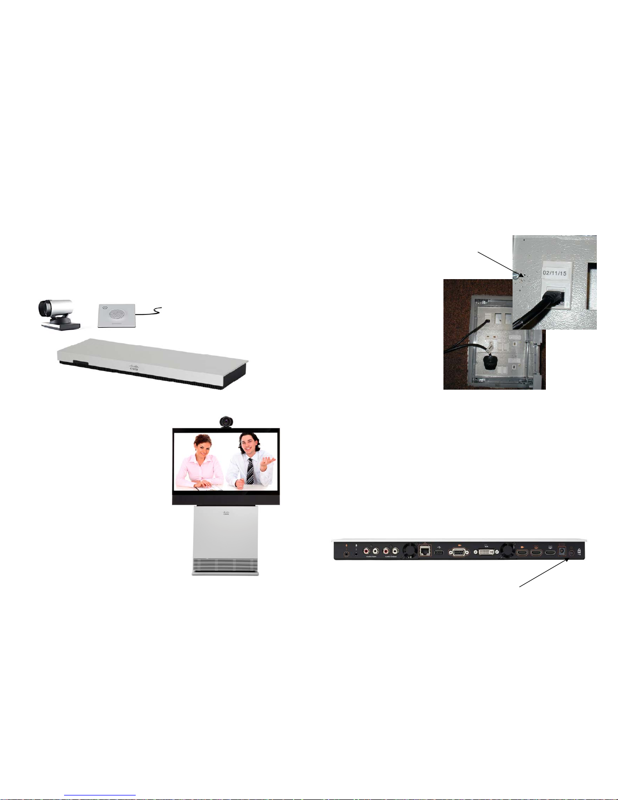
If using a mobile system, it may
be necessary to connect the
system to the power supply
and computer network.
Simply connect the power cord
to a socket and connect the
data cable to the appropriate
data point.
In general, syste
ms used for
video conferencing need to be
plugged into specially
configured data points. If you
need to connect the system in
an areas not previously set-up
please contact a member of
your support team.
Data
Connection
Rear of the C20 Codec
Power Switch
Page 3
5
System Basics
Video conferencing functions are carried out using the remote control. When the
system is not in use, it is in standby mode. The screens are black. To wake up
the system pick up the remote or press any key.
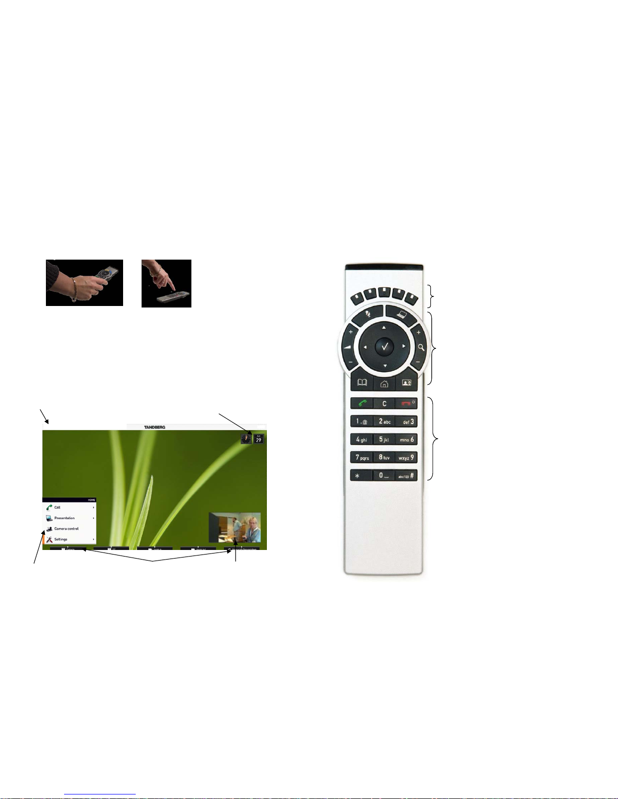
When the system is woken up, you will see the system wallpaper along
with a
number of information boxes and menus. The ‘phone number’ of the system
should be displayed in the top left corner. If this is not displayed it is likely that
your system is not properly connected. Please consult the troubleshooting
section or contact your local support team.
The menu is the interface you will use to control the system. Use the arrow keys
to select the menu item you want then press the OK button to select it.
545123456
System Address
Self View
Date & Time
Soft Keys Home Menu
6
The Remote Control
The function keys in the upper part of the
remote control reflect the softkeys on
screen
The middle part of the remote control is used
to handle video, sound, phone book, menus
and navigation
The lower part of the remote control is similar to the keypad of a mobile phone
Page 4

7
Navigating the Menus
Use the remote control to operate your TANDBERG video system. A few basic
navigation principles are all you need to know to get started.
Press the home key to show the Home menu.
The
arrow
keys in the centre of the upper part of the remote control are
used to navigate in the menus.
When the system shows the Home menu only (see below), pressing home
key again will hide the menu. To bring it back, press the home key again.
In an input field, pressing the C key will delete characters/numbers to the
left of the cursor position.
Press the home key to display the Home menu
The element
currently selected
is indicated by an
orange rectangle.
Use up and down
arrow keys to
navigate up and
down in a menu.
The little
triangle
indicates that a
submenu is
available.
8
Changing from Text to Numbers
Entry fields that expect a numeric entry will by default use the numbers from the
numeric pad. The default value for a field is shown on the right as either 123 for
a numeric field or abc for a text field. When entering values into a text field the
system works like the keypad on a mobile phone.
However, it is sometimes necessary to change between text and numbers, for
example when searching for a number in the phonebook or when entering a
dialling address of the form joe.bloggs@vc.scot.nhs.uk.
To change from text to
numeric values press the
corresponding softkey, as
displayed at the bottom of
the screen.
To enter a special character, press the
corresponding softkey and use the
arrows and tick button to select the
appropriate character.
Page 5

9
Making Calls
To Make a Call by Dialling the Number
The term “number” has a wide definition here—you may use the procedure
outlined on this page to call people by their alphanumeric address as well, for
example: “helen.karr@company.com”. However most addresses in NHS Scotland
take the form of a 9 digit number where the first three digits signify the Health
Board and the remaining 6 digits the extension number. The last 6 digits often
correspond to and ISDN telephone number, however the use of ISDN when
making calls within NHS Scotland is being phased out.
To make a call
Key in the “number” to call. If needed, switch to alphanumeric or numeric
setting by means of the abc/123 softkey. Starting to enter the n
umber
automatically open the dialling dialogue box. Note that the system will
search for matches as you write along.
Where possible, remember to type in the 9 digit IP number (eg
545123456) rather than an ISDN telephone number (eg 0131 123 4567)
This will give you better call quality.
Press the green call button.
1
2
1
2
10
Receiving a Call
When someone calls you, the system sounds an alert and a message will appear
on the screen (assuming the television / sound system is switched on).
To accept the incoming call, press the green connect button.
To reject the call, press the red disconnect button.
Please note that many systems will automatically
answer the call, but mute the microphone. To unmute the microphone press the microphone button on
the remote control.
Dial Using the Phone Book
To make a call using the phone book, press the
directory button or select phone book from the ‘CALL’
menu.
Use the arrow
keys to navigate
the directory and
select the number
you want.
Dial Using Recent Calls
Select ‘Recent calls’ from the ‘CALL’
menu then use the arrows to select the
number you want. Outgoing calls make
from the unit are signified by ‘>>‘ and incoming calls by ‘<<‘. If the call was
missed, this is displayed in red ‘<<‘
Page 6

11
During a Call
Basic Functions
Turn Mic on/off
Adjust the
Volume
Switch to a
presentation source.
Zoom the
camera in and
out.
Displays the
layout menu
Camera Control
During a call it is possible to change the position of your camera. If you are in a
point to point call with a compatible system, it is also possible to more the remote
camera. This is called far end camera control.
To access the camera controls, press one of the arrow buttons. Pressing an arrow
key again will start moving the camera. In addition, a range of softkeys will be
displayed a the bottom of the screen.
Camera Softkeys
12
If you want to send an image that is different from the default source, this can be
accomplished by selecting the presentation menu and selecting the source from
the list displayed.
Sharing Presentation
To share a presentation
Locate the computer cable and connect the PC to the video system.
Connect the audio mini-jack output from the PC (or any other source) to
the mini-jack socket of the cable to get sound.
Press the presentation button on the remote control, the default
presentation source is activated.
If the presentation fails to show, remember that most laptops require you
to press a special key combination to switch the PC image from the PC
screen to the video screen.
Page 7

13
Troubleshooting
Remote site can’t hear you
Check that your microphone is not muted.
Check the location of the microphone. In some cases it may be possible
to move the microphone closer to those speaking.
Turn off background noises such as fans and air conditioning.
Ensu
re people are not speaking in the background
.
Speak up a bit.
I can’t hear the remote sites
Ask them to do the above.
Check the volume of the system by using the remote control.
Check the volume on the television.
PC image does not display
Check the PC screen resolution. Try setting the resolution to 1024x768.
Use the function keys on the laptop to change the video outputs.
The remote site can’t see me
Check to make sure you are not in presentation mode by pressing the
presentation button. That should bring up a screen that says ‘no signal’.
Press the presentation button again to go back to the main camera.
System does not connect
For systems connection to the computer network, ensure the IP number is
displayed. If it is not displayed check the computer connection. If
necessary check with your local support team
to ensure the data point is
activated.
To dial an out
side ISDN line when connected to the computer network you
will need to dial the appropriate prefix. Try using 9 or 3 or ask your local
support team.
 Loading...