

Page 1

Cisco Business 350 Series Switches Administration Guide
First Published: 2020-05-07
Last Modified: 2024-06-27
Americas Headquarters
Cisco Systems, Inc.
170 West Tasman Drive
San Jose, CA 95134-1706
USA
http://www.cisco.com
Tel: 408 526-4000
800 553-NETS (6387)
Fax: 408 527-0883
Page 2

©
2024 Cisco Systems, Inc. All rights reserved.
Page 3

Get To Know Your Switch
This chapter contains the following sections:
Introduction
Thank you for purchasing the Cisco CBS Series Switch. The Cisco CBS Series Switches combine powerful
network performance and reliability with a complete suite of network features that you need for a solid business
network. These expandable Gigabit Ethernet switches, with Gigabit or 10-Gigabit uplinks, provide multiple
management options, rich security capabilities, and Layer-3 static routing features far beyond those of an
unmanaged or consumer-grade switch, at a lower cost than fully managed switches.
CHAPTER 1
• Introduction, on page 1
• Rack Mounting Switch, on page 2
• Wall Mounting a Switch, on page 3
• Out-Of-Band Port, on page 6
• Stacking the Switches, on page 6
• Power over Ethernet Considerations, on page 8
• Front Panel, on page 10
• Configuring Switches, on page 13
• Navigation, on page 16
Before You Begin
Before you begin installing your device, ensure that the following items are available:
• RJ-45 Ethernet cables for connecting network devices. A category 6a and higher cable is required for
10G ports; a category 5e and higher cable is required for all other ports.
• Tools for installing the hardware.
• The rack-mount kit packed with the switch contains four rubber feet for desktop placement, and
two brackets and twelve screws for rack mounting.
• If the supplied screws are lost, use replacement screws in the following size:
• Diameter of the screw head: 6.9 mm
• Length of the face of the screw head to the base of screw: 5.9 mm
• Shaft diameter: 3.94 mm
Cisco Business 350 Series Switches Administration Guide
1
Page 4

Rack Mounting Switch
Get To Know Your Switch
Warning
To prevent airflow restriction, allow clearance around the ventilation openings
to be at least 3 inches (7.6 cm).
• A computer to manage the device either via the console port or via the web-based interface. for web-based
interface the computer needs to support one of the following browsers:
• Microsoft Edge
• Firefox (version 82 or 81 or higher)
• Chrome (version 86 or 85 or higher)
• Safari over MAC (version 14.0 and higher)
Warning
Suitable for installation in information Technology Rooms in accordance with Article 645 of the national
Electric Code and NFPA 75.
Rack Mounting Switch
You can mount the switches on any standard size, 19-inch (about 48 cm) wide rack. The switch requires 1
rack unit (RU) of space, which is 1.75 inches (44.45 mm) high.
Caution
For stability, load the rack from the bottom to the top, with the heaviest devices on the bottom. A top-heavy
rack is likely to be unstable and might tip over.
To install the switch into a 19-inch standard chassis:
Procedure
Step 1 Place one of the supplied brackets on the side of the switch so that the four holes of the brackets align to the screw holes,
and then use the four supplied screws to secure it.
Step 2 Repeat the previous step to attach the other bracket to the opposite side of the switch.
Step 3 After the brackets are securely attached, the switch is now ready to be installed into a standard 19-inch rack.
Note
Use supplied brackets to rack mount the switch.
Supplied rack mounting for switch models with front mounting position. The mounting ears do not sit flush
to the front panel.
Cisco Business 350 Series Switches Administration Guide
2
Page 5

Get To Know Your Switch
Wall Mounting a Switch
Due to design differences, some of the mounting brackets will attach such that the switch will protrude about
an inch from the mounting surface.
Supplied rack mounting for switch models with front mounting position. The mounting ears sit flush to the
front panel.
Wall Mounting a Switch
You can mount the switches on a wall, using wall studs or to a firmly attached plywood mounting backboard.
Caution
Caution
Read these instructions carefully before beginning installation. Failure to use the correct hardware or to follow
the correct procedures could result in a hazardous situation to people and damage to the system.
Do not wall-mount the switch with its front panel facing up. Following safety regulations, wall mount the
switch with its front panel facing down or to the side to prevent airflow restriction and to provide easier access
to the cables.
To wall-mount a 24-port switch using brackets:
Cisco Business 350 Series Switches Administration Guide
3
Page 6
Get To Know Your Switch
Wall Mount an 8 Port Switch
Procedure
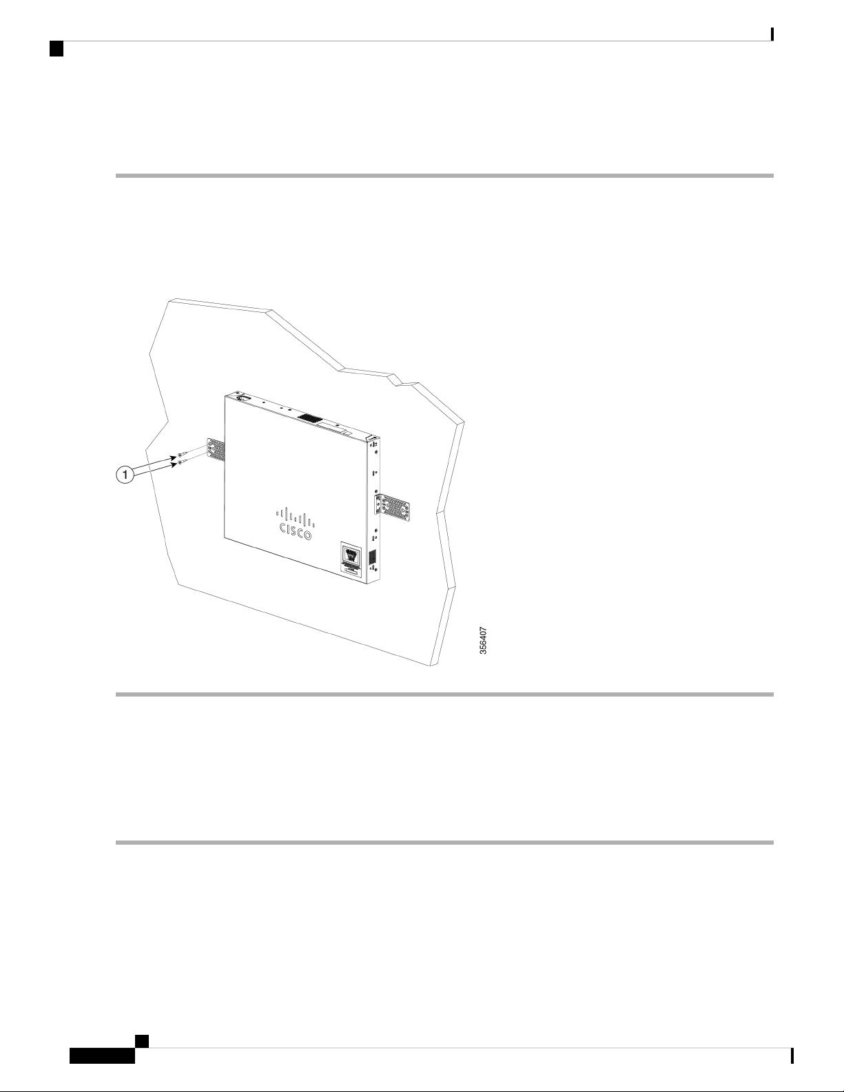
Step 1 Attach a 19-inch bracket to one side of the switch.
Step 2 Repeat the previous step to attach the other bracket to the opposite side of the switch.
Step 3 After the brackets are securely attached, mount the switch with the front panel facing down. Make sure that the switch
is attached securely to wall studs or to a firmly attached plywood-mounting backboard. Wall-mounting a 24-port switch.
Wall-mounting a 24-port
Wall Mount an 8 Port Switch
To wall-mount a 8-port switch using mounting screws, follow these steps:
Procedure
Step 1 Locate the screw template. The template is used to align the mounting screw holes.
Step 2 Position the screw template so that the edge that is marked as CABLE SIDE ENTRY faces toward the floor. Make sure
that the switch is attached securely to wall studs or to a firmly attached plywood mounting backboard.
Step 3 Peel the adhesive strip off the bottom of the screw template.
Step 4 Attach the screw template to the wall.
Step 5 Use a 0.144-inch (3.7 mm) or a #27 drill bit to drill a 1/2-inch (12.7 mm) hole in the two screw template slots.
Cisco Business 350 Series Switches Administration Guide
4
Page 7

Get To Know Your Switch
Wall Mount an 8 Port Switch
Step 6 Insert two screws in the slots on the screw template and tighten them until they touch the top of the screw template.
Installing the mounting screws on the wall
Figure 3 Installing the mounting screws on the wall
Step 7 Remove the screw template from the wall.
Step 8 Place the switch onto the mounting screws, and slide it down until it locks in place. Wall-mounting an 8-port switch
Figure 4 Wall-mounting an 8-port switch
Cisco Business 350 Series Switches Administration Guide
5
Page 8

Out-Of-Band Port
Out-Of-Band Port
The CBS350 “10G network port SKUs” support an Out-of-Band (OOB) port which can be used for the
management network. The out-of-band and the in-band ports share the same IP routing table. Thus, the same
subnet cannot be used on both the in-band and out-of-band interfaces.
The OOB port is assigned a MAC address which differs from the base MAC address and the in-band ports
addresses. This MAC address is used as the source MAC address in all frames sent by the switch on the OOB
port.
By default, VLAN 1 is configured with a default IP address 192.168.1.254, and can be accessed through any
in-band interfaces. This default IP address is used when no other address is assigned (dynamically or statically).
There is no default IP address on OOB port.
Table 1: VLAN 1 and OOB Factory Default IP settings – Old and new behavior
Get To Know Your Switch
Cisco Business firmware version 3.1.1Cisco Business firmware up to version 3.1
VLAN 1 interfaceOOB interfaceVLAN 1 interfaceOOB interface
configuration
Stacking the Switches
A stack can have multiple devices in it. Any 10G port of the switch can be used for stacking.
By default, the ports on the switch function as regular Ethernet ports, except if you configure them to do
stacking. You cannot mix the stack speeds between the switches or ports.
At least two ports must be chosen for stacking in a given switch" and those ports must be 10Gig speed. For
two switches or more to form a stack, they must be running the same version of the firmware. This is the more
reason SG series switches cannot be stacked with CBS series switches. CBS250 series switches do not have
stacking capabilities.
Some switches have their stack LEDs numbered 1, 2, 3, and 4 to indicate Active, Standby, and Member while
the others types use the system LED flashing behavior to describe the same thing.
Note
Stack ports must have the same speed capability on the module or cable plug in.
Default IP + DHCPDHCP enableDefault IP + DHCPIP settings
None"IP address DHCP"NoneNoneInterface CLI
Bonjour enabledNoneNoneBonjour enabledOther
The switch can only be stacked without Mesh topology. The switches in the same stack are connected together
through their stack ports. Depending on the type of stack ports and the desired speed, you may need Cat6a
Ethernet cables or Cisco approved modules or cables for the switches.
Cisco Business 350 Series Switches Administration Guide
6
Page 9

Get To Know Your Switch
Feature Support on Hybrid Mode
Some network switches have the ability to be connected to other switches and operate together as a single
unit. These configurations are called stacks, and they are useful for quickly increasing the capacity of your
network.
Stack Management
The Cisco Business switches have a couple of different stacking modes, and you can stack different models.
Also, you need to note what feature may or may not be available in different stacking modes (native or hybrid).
• Native Stacking- The switch is part of a stack in which all of the units are of the same type.
• Hybrid Stacking – The switch is part of a stack that can consist of either mixed type of CBS350 devices.
Cisco Business Switch Stacking Mode Selector
This tool will guide you to selecting the correct stacking settings for your 10G Cisco Business 350 series
switch. Click on the link below to access the tool.
https://www.cisco.com/c/en/us/support/docs/smb/switches/Cisco-Business-Switching/
kmgmt-2799-switch-stack-selector-cbs.html
Note
You cannot stack the legacy switches with the new Cisco Business stackable switches. If you are stacking the
legacy switches, consult the following link: https://www.cisco.com/c/en/us/support/docs/smb/switches/
cisco-350x-series-stackable-managed-switches/
smb5367-feature-support-comparison-between-the-cisco-stackable-manag.html
Feature Support on Hybrid Mode
The feature set of the CBS350 SKUs with 10G network ports and the feature CBS350 SKUs with 10G uplink
ports are nearly identical. However, there are a few differences in feature support and table sizes between the
2 “sub-types”. The Cisco Business switches hybrid stack mode will support the lower denominator for these
features/tables The following table lists the feature differences between the 2 sub-types and the setting applied
in hybrid mode:
Hybrid mode works in any combination of stacking albeit reduced performance, MAC table size for example
can be reduced; but switches of the same model number (same PID) can take advantage of native stacking
mode. Some switches with different PID can stack in native mode as well, other combinations, however, can
only stack in hybrid mode.
In general, except for the CBS350-48XT-4X, all CBS350 switches that support stacking and have designated
uplink ports in their PID can stack natively among themselves, and those that do not have uplink ports,
including the CBS350-48T-4X can stack, among themselves, in native mode as well. The hybrid mode staking
comes into play only when mixing these two blocks, uplink supporting devices and non-uplink supporting
devices. So. knowing the exact PID of a given switch is so crucial when it comes to stacking mode
determination. The CBS350-48T-4X, although has 4X at the end of the PID that should designate this as
supporting an uplink, it is not the case, this 4X designation in this switch does not indicate uplink, instead,
they are network port (downlink port) as are the other ports in the switch.
Changing stacking mode from Native to Hybrid will force a switch to reboot and most of its settings in its
startup configuration will reset to default; on the other hand, changing the stacking mode from Hybrid to
Native will force the unit to reboot, but the settings will not reset back to default.
Cisco Business 350 Series Switches Administration Guide
7
Page 10

Power over Ethernet Considerations
Get To Know Your Switch
Feature
Green Settings (Short
reach and Energy Detect)
groups
supported
interfaces
tunnel/ ISATAP routing
tunnel
CBS350 “10G uplink port
SKUs”
Per SKU and port type
behavior
SKUs”
Per SKU and port type
behavior
Hybrid stackCBS350“10G network port
Not SupportedSupportedNot SupportedOOB port
Per SKU and port type
behavior
16K32K or 64K16KMAC table size
2K4K2KNumber of Multicast
1K- reserved2K- reserved1K- reservedNumber of ACEs
9927392992Total number of IP entries
1K – reserved8K – reserved1K – reservedARP table size
106200106Max number of IPv6
400 seconds630 seconds400 secondsMax MAC table aging
Not supportedSupportedNot supportedIPv6 Manual Tunnel/ 6tp4
PoE support
SKUs
Mapping entries
Power over Ethernet Considerations
Some switches support PoE while others do not. The switch models that support PoE have a P in their model
number, such as: CBSxxx-xxP-xx. If your switch is one of the Power over Ethernet (PoE) models, consider
the following power requirement.
Warning
The switch is to be connected only to PoE networks without routing to the outside plant.
Table 2: Switches with Power Over Ethernet
Per SKU typeNot supportedSupported on specific
0320Default number of VLAN
On VLAN 1On VLAN 1On VLAN 1Default IP address
PoE PSE SupportPoE PD Chipset TypeDescriptionSKU Name
AF/AT1*69208M8-Port 2.5G PoE Managed SwitchCBS350-8MGP-2X
Cisco Business 350 Series Switches Administration Guide
8
Page 11

Get To Know Your Switch
Power over Ethernet Considerations
PoE PSE SupportPoE PD Chipset TypeDescriptionSKU Name
CBS350-8MP-2X
CBS350-24MGP-4X
CBS350-12NP-4X
CBS350-24NGP-4X
CBS350-48NGP-4X
Switch
Switch
Switch
Switch
Switch
AF/AT1*69208M8-Port 2.5G PoE Stackable Managed
AF/AT/60W1*69208M + 1*6920424-Port 2.5G PoE Stackable Managed
AF/AT/60W3 * TPS238812-Port 5G PoE Stackable Managed
AF/AT/60W4* TPS238824-Port 5G PoE Stackable Managed
7* TPS238848-Port 5G PoE Stackable Managed
AF/AT
/60W
AF/ATTPS23888-Port Gigabit PoE Managed SwitchCBS350-8P-2G
AF/ATTPS23888-Port Gigabit PoE Managed SwitchCBS350-8P-E-2G
AF/ATTPS23888-Port Gigabit PoE Managed SwitchCBS350-8FP-2G
AF/ATTPS23888-Port Gigabit PoE Managed SwitchCBS350-8FP-E-2G
AF/AT2*TPS238816-Port Gigabit PoE Managed SwitchCBS350-16P-2G
AF/AT2*TPS238816-Port Gigabit PoE Managed SwitchCBS350-16P-E-2G
CBS350-24P-4X
CBS350-24P-4X
CBS350-24FP-4X
CBS350-48P-4X
CBS350-48FP-4X
AF/AT2*TPS238816-Port Gigabit PoE Managed SwitchCBS350-16FP-2G
AF/AT3*TPS238824-Port Gigabit PoE Managed SwitchCBS350-24P-4G
AF/AT3*TPS238824-Port Gigabit PoE Managed SwitchCBS350-24FP-4G
AF/AT6*TPS238824-Port Gigabit PoE Managed SwitchCBS350-48P-4G
AF/AT6*TPS238848-Port Gigabit PoE Managed SwitchCBS350-48FP-4G
AF/AT3*TPS238824-Port Gigabit PoE Stackable Managed
Switch with 10G Uplinks
AF/AT3*TPS238824-Port Gigabit PoE Stackable Managed
Switch with 10G Uplinks
AF/AT6*TPS238848-Port Gigabit PoE Stackable Managed
Switch with 10G Uplinks
AF/AT6*TPS238848-Port Gigabit PoE Stackable Managed
Switch with 10G Uplinks
AF/AT6*TPS238848-Port Gigabit PoE Stackable Managed
Switch with 10G Uplinks
Cisco Business 350 Series Switches Administration Guide
9
Page 12

Front Panel
Get To Know Your Switch
Caution
Front Panel
Consider the following when connecting a PoE switch. The PoE switches are PSE (Power Sourcing Equipment)
that are capable of supplying DC power to attaching powered devices (PD). These devices include VoIP
phones, IP cameras, and wireless access points. The PoE switches can detect and supply power to pre-standard
legacy PoE PD. Due to the PoE legacy support, it is possible that a PoE switch acting as a PSE may mistakenly
detect and supply power to an attaching PSE, including other PoE switches, as a legacy PD. Even though PoE
switches are PSE, and as such should be powered by AC, they could be powered up as a legacy PD by another
PSE due to false detection. When this happens, the PoE switch may not operate properly and may not be able
to properly supply power to its attaching PDs.
To prevent false detection, you should disable PoE on the ports on the PoE switches that are used to connect
to PSEs. You should also first power up a PSE device before connecting it to a PoE switch. When a device
is being falsely detected as a PD, you should disconnect the device from the PoE port and power recycle the
device with AC power before reconnecting its PoE ports.
The ports, LEDs, and Reset button are located on the front panel of the switch, as well as the following
components:
Cisco Business 350 Series Model
Note
Models may differ within the CBS 350 series and this is just a representation of a model within the series.
• There are 2 device types with different console interface:
• Console port with RJ-45 and mini USB connector if both are connected the Mini USB has precedence
over the RJ-45
• RJ-45 connector only type of console.
The console interface connects a serial cable to a computer serial port so that it can be configured using
a terminal emulation program or mini USB cable (depending on the connector).
Cisco Business 350 Series Switches Administration Guide
10
Page 13

Get To Know Your Switch
Front Panel
• USB Port—The USB port connects the switch to a USB device so that you can save and restore the
configuration files, firmware images, and SYSLOG files through the connected USB device. The USB
port supports the FAT32 file system.
• RJ-45 Ethernet Ports—The RJ-45 Ethernet ports connect network devices, such as computers, printers,
and access points, to the switch.
• SFP+ Port (if present)—The small form-factor pluggable plus (SFP+) are connection points for modules
so that the switch can link to other switches. These ports are also commonly referred to as mini 10GigaBit
Interface Converter ports. The term SFP+ is used in this guide.
• The SFP+ ports (if present) are compatible with the following Cisco SFP 1G optical modules
MGBSX1, MGBLX1, MGBLH1, MGBT1, as well as other brands.
• The SFP+ ports are compatible with the following Cisco SFP 1G optical modules MGBSX1,
MGBLX1, MGBLH1, MGBT1, as well as other brands.
• The Cisco SFP+ Copper Cable modules that are supported in the Cisco switches are:
SFP-H10GB-CU1M, SFP-H10GB-CU3M, and SFP-H10GB-CU5M.
• The LEDs of the corresponding RJ-45 port flash green to respond to the SFP interface traffic.
• Small form-factor pluggable (SFP) ports are connection points for modules, so the switch can link to
other switches.
• Some SFP interfaces are shared with one other RJ-45 and SFP+ port, called a combo port. When the SFP
is active, the adjacent RJ-45 port is disabled.
• Reset button is used to reset or reboot the switch. The table below displays the reset behavior on the
switch.
Press Type
1- 5 seconds
New Behavior (Firmware 3.2 and
on)
Old Behavior (Firmware prior to
3.2)
ReloadSystem LED is green, releasing
button does not cause reload.
6- 10 seconds
ReloadSystem LED flash green,
releasing button during this period
will cause device reload, but
system is not set to factory
default.
11-15 seconds
Factory defaultSystem LED is green, releasing
button does not cause reload
16-20 seconds
Factory defaultSystem LED flashes green,
releasing button during this period
will cause device reload to factory
default
> 20 seconds
Factory defaultSystem LED is green, releasing
button does not cause reload
Cisco Business 350 Series Switches Administration Guide
11
Page 14

Front Panel LEDs
Get To Know Your Switch
Note
Stack Behavior
The reset button disable setting is applied to all units in the stack, meaning that
if configured, the reset button on all units in the stack are disabled, and if not
configured the reset button on all units in the stack are enabled. This applies also
to units that join an existing stack.
• OOB Port (if present)—The Out of Band (OOB) port is a CPU Ethernet port that can be used only as a
management interface. Bridging between the OOB port and the in-band Layer 2 interface is not supported.
This does not appear on 250 devices.
• Multi-Gigabit Ethernet Ports (if present) —Highlighted in blue, these ports support speeds up to 2.5 Gbps
or 5 Gbps on Cat5e cables. The maximum speed supported is printed on the blue shade under the port.
Uplink ports on CBS350-8MGP-2X also support multi-Gigabit speed. In this case, port speed can reach
10Gbps. Most of the cabling deployed worldwide is Cat5e, and previously limited to 1 Gbps at 100
meters. Cisco multi-Gigabit Ethernet enables speeds up to 2.5 or 5 Gbps on the same infrastructure
without replacing a cable.
• 60-Watt PoE Ports (if present)- The 60-Watt PoE port doubles the maximum PoE power delivered on
Front Panel LEDs
The following are the global LEDs found on the devices:
• System—(Green) The LED lights steady when the switch is powered on, and flashes when booting,
The following LEDs describe the stacking status of the unit.
• *Stack ID LED (Green)- The LED lights steady when the switch is stacked and the corresponding number
• *Active Unit ID LED- indicating this is the stack active unit.
Note
• System LED- Every 20 seconds, the System LED will flash according to unit ID of the member unit.
the port to 60W.
performing self-tests, or acquiring an IP address. If the LED flashes Amber, the switch has detected a
hardware or firmware failure, and/or a configuration file error.
indicates its Stack ID.
* These two LEDs are only available on certain models.
• Flash = LED going off and then on again.
• According to unit ID of the unit. This means
• Unit 1 (if not active unit)- system LED will flash 1 time
• Unit 2 (if not active unit)- system LED will flash 2 times
• Unit 3- system LED will flash 3 times
• Unit 4-system LED will flash 4 times;
Cisco Business 350 Series Switches Administration Guide
12
Page 15

Get To Know Your Switch
Configuring Switches
• The duration of each flash (LED off time) will be as follows:
• LED off time (in each flash) ~ 0.5 seconds.
• “Interim” LED on (between 2 LED offs) ~ 0.5 seconds
• If a member unit is removed from the stack, its system LED will continue to flash according to
above definition.
The following are per port LEDs:
• LINK/ACT—(Green) Located on the left of each port. The LED lights steady when a link between the
corresponding port and another device is detected, and flashes when the port is passing traffic.
• SFP+ (if present)—(Green) Located on the right of a 10G port. The LED lights steady when a connection
is made through the shared port, and flashes when the port is passing traffic.
• XG—(Green) Located on the right of a 10G port. The LED lights steady when another device is connected
to the port, is powered on, and a 10 Gbps link is established between the devices. When the LED is off,
the connection speed is under 10 Gbps or nothing is cabled to the port.
• Gigabit—(Green) Located on the right of the 1G port. The LED lights steady when another device is
connected to the port, is powered on, and a 1000 Mbps link is established between the devices. When
the LED is off, the connection speed is under 1000 Mbps or nothing is cabled to the port. (This feature
is only available on certain models).
• PoE (if present)—(Amber) Located on the right of the port. The LED lights steady when power is being
supplied to a device attached to the corresponding port. (This feature is only available on certain models).
Configuring Switches
The switch can be accessed and managed over your IP network using the web-based interface, or by using
the switch’s command-line interface through the console port. Using the console port requires advanced user
skills and is only supported on certain models.
The following table shows the default settings used when configuring your switch for the first time.
Default ValueParameter
ciscoUsername
ciscoPassword
192.168.1.254LAN IP
Configuring Your Switch Using the Web-based Interface
To access the switch with a web-based interface, you must know the IP address that the switch is using. The
switch uses the factory default IP address of 192.168.1.254, with a subnet of /24. When the switch is using
the factory default IP address, the System LED flashes continuously. When the switch is using a DHCP
server-assigned IP address or an administrator has configured a static IP address, the System LED is a steady
green (DHCP is enabled by default).
Cisco Business 350 Series Switches Administration Guide
13
Page 16

Configuring Your Switch Using the Web-based Interface
If you are managing the switch through a network connection and the switch IP address is changed, either by
a DHCP server or manually, your access to the switch will be lost. You must enter the new IP address that
the switch is using into your browser to use the web-based interface. If you are managing the switch through
a console port connection, the link is retained.
To configure the switch using the web-based interface:
Procedure
Step 1 Power on the computer and your switch.
Step 2 Connect the computer to any network port.
Step 3 Set up the IP configuration on your computer.
a) If the switch is using the default static IP address of 192.168.1.254/24, you must choose an IP address for the computer
in the range of 192.168.1.2 to 192.168.1.253 that is not already in use.
b) If the IP addresses will be assigned by DHCP, make sure that your DHCP server is running and can be reached from
the switch and the computer. You may need to disconnect and reconnect the devices for them to discover their new
IP addresses from the DHCP server.
Get To Know Your Switch
Note
Details on how to change the IP address on your computer depend upon the type of architecture and operating system
that you are using. Use your computers local Help and Support functionality and search for “IP Addressing.”
Step 4 Open a web browser window.
Step 5 Enter the switch IP address in the address bar and press Enter. For example, http://192.168.1.254.
Step 6 When the login page appears, choose the language that you prefer to use in the web-based interface and enter the username
and password.
The default username is cisco. The default password is cisco. Usernames and passwords are both case sensitive.
Step 7 Click Log In.
Step 8 If this is the first time that you have logged on with the default username and password, the Change username and
Password. Enter a new username and password and confirm.
If this is the first time that you have logged on with the default username and password, the Change username and Password
page opens
Note
Please refer to the password complexity rule section in Login Settings, on page 262 before creating a password.
Step 9 Click Apply.
Caution
Make sure that any configuration changes made are saved before exiting from the web-based interface by clicking on the
Save icon. Exiting before you save your configuration results in all changes being lost.
The Getting Started page opens. You are now ready to configure the switch. Refer to the Administration Guide or see
the help pages for further information.
Cisco Business 350 Series Switches Administration Guide
14
Page 17

Get To Know Your Switch
Configuring Your Switch Using the Console Port
Configuring Your Switch Using the Console Port
To configure the switch using the console port, which is only supported on certain models, proceed with the
following steps:
Procedure
Step 1 Connect a computer to the switch console port using a Cisco console cable (purchased separately) or a cable with mini
USB connector.
Step 2 Start a console port utility such as Hyper Terminal on the computer.
Step 3 Configure the utility with the following parameters:
• 115200 bits per second
• 8 data bits
• no parity
• 1 stop bit
• no flow control
Step 4 Enter a username and password. The default username is cisco, and the default password is cisco. Usernames and passwords
are both case sensitive.
If this is the first time that you have logged on with the default username and password, the following message appears:
Please change your username AND password from the default settings. Change of credentials
is required for better protection of your network.
Please note that new password must follow password complexity rules
Step 5 Set a new administrator username and password.
Caution
Make sure that any configuration changes made are saved before exiting.
You are now ready to configure the switch. See the CLI Guide for your switch.
Note
If you are not using DHCP on your network, set the IP address type on the switch to Static and change the static IP address
and subnet mask to match your network topology. Failure to do so may result in multiple switches using the same factory
default IP address of 192.168.1.254.
Console access also provides additional interfaces for debug access which are not available via the web interface. These
debug access interfaces are intended to be used by a Cisco Support Team personnel, in cases where it is required to debug
device’s behavior. These interfaces are password protected. The passwords are held by the Cisco support team. The device
supports the following debug access interfaces:
• U-BOOT access during boot sequence
• Linux Kernel access during boot sequence
Cisco Business 350 Series Switches Administration Guide
15
Page 18

Navigation
• Run time debug modes- allows Cisco support team to view device settings and apply protocol and layer 1 debug
commands and settings. The run time debug mode is accessible over telnet and SSH terminals in addition to the
console.
Navigation
The navigation menu, located at the top right of each UI page, lists the device’s main features. You can access
each feature’s UI pages using a series of cascading menus. To access an individual UI page, click the
corresponding feature tab in the navigation menu to display a menu of subcategories. Select a subcategory
and repeat this process until you see the desired page, and then select the page to display it in the main window.
Basic or Advanced Display Mode
The product supports many features, and therefore the WEB GUI includes hundreds of configuration and
display pages. These pages are divided into the following display modes:
Get To Know Your Switch
• Basic—Basic subset of configuration options are available. If you are missing some configuration option,
select the Advanced mode in the device header.
• Advanced—Full set of configuration options are available.
When the user switches from basic to advanced, the browser reloads the page. However, after reloading, the
user stays on the same page. When the user switches from advanced to basic, the browser reloads the page.
If the page exists also on the basic mode, the user stays on the same page. If the page does not exist in the
basic mode, the browser will load the first page of the folder which was used by the user. If the folder does
not exist, the Getting Started page will be displayed.
If there is an advanced configuration, and the page is loaded in basic mode, a page-level message will be
displayed to the user (e.g, there are 2 radius servers configured but in basic mode only a single server can be
displayed, or there is 802.1X port authentication with time range configured but time range is not visible in
basic mode). When switching from one mode to another, any configuration which was made on the page
(without Apply) is deleted.
Cisco Business 350 Series Switches Administration Guide
16
Page 19

Getting Started
This chapter contains the following section:
• Getting Started, on page 17
Getting Started
This section will guide you on how to install and manage your device.
Click on Getting Started to access the page where you can use the various links and follow the on-screen
instructions to quickly configure your switch.
Basic or Advanced Display Mode
The switch's WEB GUI includes hundreds of configuration and display pages. These pages are divided into
the following display modes:
• Basic—Basic subset of configuration options.
• Advanced—Full set of configuration options are available
CHAPTER 2
When switching from one mode to another, any configuration which was made on the page (without Apply)
is deleted.
Initial Setup
Stack Management, on page 61Manage Stack
TCP/UDP Services, on page 284Change Management Applications
and Services
IPv4 Interface, on page 201Change Device IP Address
VLAN Settings, on page 143Create VLAN
Port Settings, on page 119Configure Port Settings
Device Status
System Summary, on page 33System Summary
Cisco Business 350 Series Switches Administration Guide
17
Page 20

Getting Started
Getting Started
Interface, on page 36Port Statistics
Statistics, on page 50RMON Statistics
RAM Memory, on page 57View Log
Quick Access
User Accounts, on page 62Change Device Password
Firmware Operations, on page 74Upgrade Device Software
File Operations, on page 76Backup Device Configuration
MAC-Based ACL, on page 329Create MAC-Based ACL
IPv4-based ACL, on page 331Create IP-Based ACL
QoS Properties, on page 341Configure QoS
SPAN and RSPAN , on page 44Configure SPAN
There are four hot links on the Getting Started page that take you to Cisco web pages for more information.
Clicking on the Support link takes you to the device product support page, and clicking on the Forums link
takes you to the Support Community page. Clicking on the Virtual Assistant will take you to the virtual
assistant where you can ask your questions and clicking on CBD will take you to the Cisco Business Dashboard
application where you can manage your network.
Cisco Business 350 Series Switches Administration Guide
18
Page 21

Dashboard
CHAPTER 3
Dashboard
This chapter contains the following section:
• Dashboard, on page 19
The dashboard is a collection of 8 squares, initially empty, that can be populated by various types of information.
You can select a number of modules from the available modules and place them in this grid. You can also
customize settings of the currently displayed modules. When the dashboard loads, the modules you selected
for the dashboard are loaded in their locations in the grid. The data in the modules is updated, in intervals
depending on the module type.
When you open the dashboard, a wire frame view of the grid is displayed. To display modules that aren’t
currently being displayed, click Customize. Add modules by selecting a module from the list of modules on
the right and dragging and dropping it to any space in the grid.
The modules are divided into the following groups:
• Small Modules are modules that take up a single square.
• Large Modules take up two squares.
If you drag a module into a space currently occupied, the new module replaces the previous one. You can
rearrange the placement of the modules in the grid by dragging a module from one occupied grid position to
another position. Only when you click Done are the modules populated by the relevant information. The title
bar of each module in the dashboard displays the title of the module and three buttons.
• Pencil — Opens configuration options (depending on the module).
• Refresh — Refreshes the information.
• X — Removes the module from the dashboard.
Cisco Business 350 Series Switches Administration Guide
19
Page 22

Dashboard
Dashboard
Table 3: Small Modules
System Health
Resource Utilization
The System Health displays information about device health.
• Fan Status
• Yellow— A fan has failed and is backed up by a redundant
fan.
• Green—Fan is operational.
• Red—Fan is faulty.
• Thermometer Status
• Green —Temperature is OK.
• Yellow—Temperature generates a warning.
• Red—Temperature is critical.
This module displays the utilization status in terms of a percentage of
the various system resources as a bar chart
The resources monitored are:
• Multicast Groups—Percentage of Multicast groups that exist out
of the maximum possible number that are permitted to be defined.
• MAC Address Table—Percentage of MAC Address table in use.
Identification
• TCAM—Percentage of TCAM used by QoS and ACL entries.
• CPU—Percentage of CPU being used.
This module displays basic information regarding the device. It displays
the following fields:
• System Description—Displays description of the device.
• Host Name—Entered in the System Settings, on page 59 or default
is used.
• Firmware Version—Current firmware version running on device.
• MAC Address—MAC address of the device.
• Serial Number—Serial number of the device.
• System Location (if configured)—Enter the physical location of
the device.
• System Contact (if configured)—Enter the name of a contact person.
• Total Available Power (for PoE devices only)—Amount of power
available to the device.
• Current Power Consumption (for PoE devices only)—Amount of
power consumed by the device.
Cisco Business 350 Series Switches Administration Guide
20
Page 23

Dashboard
Dashboard
PoE Utilization
Table 4: Large Modules
This module displays a graphic representation of the PoE utilization
status. For a standalone unit, this module displays a gauge with a dial
of values from 0-100. The section of the dial from the traps threshold
to 100 is red. In the middle of the gauge, the actual PoE utilization value
is shown in watts.
Each bar represents the PoE utilization percentage value of the device
on a scale of 0 to 100. If the PoE utilization is higher than the traps
threshold, the bar is red. Otherwise the bar is green. When hovering on
a bar, a tool tip appears showing the actual PoE utilization of the device
in watts. Additional views can be selected in the configuration options
(pencil icon in upper-right corner).
• Refresh Time—Select one of the displayed options.
• PoE Global Properties—Link to the Port Management > PoE >
Properties page.
• PoE Port Settings—Link to the Port Management > PoE >
Settings page.
Note
This section is only relevant for devices supporting PoE.
Latest Logs
This module contains information about the five latest events logged by
the system as SYSLOGs. The following configuration options
(right-hand corner) are available:
• Severity Threshold—Described in Log Settings, on page 71.
• Refresh Time—Select one of the options displayed.
• View logs—Click to open RAM Memory, on page 57 .
Cisco Business 350 Series Switches Administration Guide
21
Page 24

Dashboard
Dashboard
Suspended Interfaces
Stack Topology
This module displays interfaces that have been suspended in either
device or table view. The view is selected in the configuration optionsDisplay Option (pencil icon in upper-right corner).
• Device View—In this view, the device is displayed. When units
are connected in a stack, a drop-down selector enables the user to
select the device to be viewed. All suspended ports in the device
are shown as red.
• Table View—In this view, there is no need to select a specific stack
unit. Information is displayed in table form as follows:
• Interface—Port or LAG that was suspended
• Suspension Reason—Reason interface was suspended
• Auto-recovery current status—Has auto recovery been enable
for the feature that caused the suspension.
The following configuration options (right-hand corner) are available:
• Refresh Time—Select one of the options displayed
• Error Recovery Settings—Click to open Error Recovery Settings,
on page 122.
This module is a graphic representation of the stack topology and is
identical in behavior to the Stack Topology View. It displays the
following fields:
• Stack Topology—Either Chain or Ring.
• Stack Active Unit—Number of unit functioning as the active unit
of the stack.
Hovering over a unit in the module displays a tool tip identifying the
unit and providing basic information on its stacking ports. Hovering
over a stack connection in the module displays a tool tip detailing the
connected units and the stacking ports generating the connection.
Cisco Business 350 Series Switches Administration Guide
22
Page 25

Dashboard
Dashboard
Port Utilization
Traffic Errors
This section displays the port utilization on the device. The view is
selected in the configuration options (pencil icon in upper-right corner).
• Display Mode—Device View- Displays the device Hovering over
a port displays information about it.
• Display Mode—Chart View- A list of ports and how they are being
used is displayed. For each port, the following port utilization
information can be viewed.
• Tx—% (red)
• Rx—% (blue)
• Refresh Time—Select one of the displayed options.
• Interface Statistics—Link to the Status and Statistics> Interface.
This module displays the number of error packets of various types that
are counted on the RMON statistics. The view is selected in the
configuration options (pencil icon in upper-right corner).
• Display Mode- Device View
The device module mode displays a diagram of the device. All
suspended ports in the device are shown as red.
Hovering over a suspended port displays a tool tip with the
following information:
• Port name.
• If the port is a member of a LAG, the LAG identity of the
port.
• Details of the last error logged on the port.
• Display Mode- Table View
• Interface—Name of port
• Last Traffic Error—Traffic error that occurred on a port and
the last time the error occurred.
• Refresh Time—Select one of the refresh rates.
• Traffic Error Information—Click to link to the Statistics, on page
50.
Cisco Business 350 Series Switches Administration Guide
23
Page 26

Dashboard
Dashboard
Cisco Business 350 Series Switches Administration Guide
24
Page 27

CHAPTER 4
Configuration Wizards
This chapter contains the following sections:
• Getting Started Wizard, on page 25
• VLAN Configuration Wizard, on page 26
• ACL Configuration Wizard, on page 27
Getting Started Wizard
The Getting Started Wizard will assist you in the initial configuration of the device.
Procedure
Step 1 In Configuration Wizards > GettingStarted Wizard, click Launch Wizard.
Step 2 Click Launch Wizard and Next.
Step 3 Enter the fields in the General Information tab:
• System Location—Enter the physical location of the device.
• System Contact—Enter the name of a contact person.
• Host Name—Select the host name of this device. This is used in the prompt of CLI commands:
• Use Default—The default hostname (System Name) of these switches is: switch 123456, where 123456
represents the last three bytes of the device MAC address in hex format.
• User Defined—Enter the hostname. Use only letters, digits, and hyphens. Host names cannot begin or end
with a hyphen. No other symbols, punctuation characters, or blank spaces are permitted (as specified in
RFC1033, 1034, 1035).
Step 4 Click Next.
Step 5 Enter the fields in the IP Settings tab:
• Interface—Select the IP interface for the system.
• IP Interface Source—Select one of the following options:
• DHCP—Select for the device to receive its IP address from a DHCP server.
Cisco Business 350 Series Switches Administration Guide
25
Page 28

VLAN Configuration Wizard
• Static—Select to enter the IP address of the device manually.
• If you selected Static as the IP interface source, enter the following fields:
• IP Address—IP address of the interface.
• Network Mask—IP mask for this address.
• Administrative Default Gateway—Enter the default gateway IP address.
• DNS Server—Enter the IP address of the DNS server.
Step 6 Click Next
Step 7 Enter the fields in the User Account tab:
• Username—Enter a new user name between 0 and 20 characters. UTF-8 characters are not permitted.
• Password—Enter a password (UTF-8 characters are not permitted).
• Confirm Password—Enter the password again.
Configuration Wizards
• Password Strength —Displays the strength of password.
• Keep current username and password—Select to keep current username and password.
Step 8 Click Next
Step 9 Enter the fields in the Time Settings tab:
• Clock Source—Select one of the following:
• Manual Settings—Select to enter the device system time. If this is selected, enter the Date and Time.
• Default SNTP Servers—Select to use the default SNTP servers.
Note
The default SNTP servers are defined by name, thus DNS must be configured and operational.
• Manual SNTP Server—Select and enter the IP address of an SNTP server.
Step 10 Click Next to view a summary of configuration that you entered.
Step 11 Click Apply to save the configuration data.
VLAN Configuration Wizard
The VLAN Configuration Wizard will assist you in configuring the VLANs. Each time you run this wizard,
you can configure the port memberships in a single VLAN. To use the VLAN Configuration Wizard to
configure your VLANs follow these steps:
Cisco Business 350 Series Switches Administration Guide
26
Page 29

Configuration Wizards
ACL Configuration Wizard
Procedure
Step 1 In Configuration Wizards > VLANConfiguration Wizard, click Launch Wizard.
Step 2 Click Launch Wizard and Next.
Step 3 Select the ports that are to be configured as trunk port (by clicking with mouse on the required ports in the graphical
display). Ports that are already configured as Trunk ports are pre-selected.
Step 4 Click Next.
Step 5 In the VLAN Configuration section, configure the following::
• VLAN ID—Select the VLAN you want to configure. You can select either an existing VLAN or New VLAN.
• New VLAN ID—Enter the VLAN ID of a new VLAN.
• VLAN Name—Optionally, enter VLAN name.
Step 6 Select the trunk ports that are to be configured as untagged members of the VLAN (by clicking with mouse on the
required ports in the graphical display). The trunk ports that are not selected in this step becomes tagged members of
the VLAN.
Step 7 Click Next.
Step 8 Select the ports are that to be the access ports of the VLAN. Access ports of a VLAN is untagged member of the VLAN.
(by clicking with mouse on the required ports in the graphical display).
Step 9 Click Next to see the summary of the information that you entered.
Step 10 Click Apply.
ACL Configuration Wizard
The ACL Configuration Wizard will assist you when creating a new ACL, or editing an existing ACL. To
add or modify an existing ACL, complete the following steps:
Procedure
Step 1 In Configuration Wizards > ACL Configuration Wizard, click Launch Wizard.
Step 2 To create a new ACL, click Next. To edit an existing ACL, choose it from the ACL drop-down list and then click Next.
Step 3 Enter the fields:
• ACL Name—Enter the name of a new ACL.
• ACL Type—Select the type of ACL: IPv4 or MAC.
Step 4 For the ACE Configuration, configure the following fields:
• Action on match—Select one of the options:
• Permit Traffic—Forward packets that meet the ACL criteria.
Cisco Business 350 Series Switches Administration Guide
27
Page 30

ACL Configuration Wizard
• Deny Traffic—Drop packets that meet the ACL criteria.
• Shutdown Interface—Drop packets that meet the ACL criteria, and disable the port from where the packets
received.
Step 5 For a MAC-based ACL, enter the fields:
Configuration Wizards
Source MAC Address
Source MAC Value
Destination MAC Address
Destination MAC Value
Destination MAC Wildcard
Mask
Select Any if all source address are acceptable or User defined to enter a source address
or range of source addresses.
Enter the MAC address to which the source MAC address is to be matched and its mask
(if relevant).
Enter the mask to define a range of MAC addresses.Source MAC Wildcard Mask
Select Any if all destination addresses are acceptable or User defined to enter a destination
address or a range of destination addresses.
Enter the MAC address to which the destination MAC address is to be matched and its
mask (if relevant).
Enter the mask to define a range of MAC addresses. Note that this mask is different than
in other uses, such as subnet mask. Here, setting a bit as 1 indicates don't care and 0
indicates to mask that value.
Note
Given a mask of 0000 0000 0000 0000 0000 0000 1111 1111 (which means that you
match on the bits where there is 0 and don't match on the bits where there is 1's). You
need to translate the 1's to a decimal integer and you write 0 for each four zeros. In this
example since 1111 1111 = 255, the mask would be written: as 0.0.0.255.
If Time Range is selected, select the time range to be used.Time Range Name
Step 6 For a IPv4-based ACL, enter the fields:
Protocol
Select one of the following options to create an ACL based on a specific protocol:
• Any (IP)—Accept all IP protocols packets
• TCP—Accept Transmission Control Protocols packets
• UDP—Accept User Datagram Protocols packets
• ICMP—Accept ICMP Protocols packets
• IGMP—Accept IGMP Protocols packets
Select a port from the drop-down list.Source Port for TCP/UDP
Select a port from the drop-down list.Destination Port for
TCP/UDP
Source IP Address
Select Any if all source address are acceptable or User defined to enter a source address
or range of source addresses.
Cisco Business 350 Series Switches Administration Guide
28
Page 31

Configuration Wizards
ACL Configuration Wizard
Enter the IP address to which the source IP address is to be matched.Source IP Value
Source IP Wildcard Mask
Enter the mask to define a range of IP addresses. Note that this mask is different than in
other uses, such as subnet mask. Here, setting a bit as 1 indicates don't care and 0 indicates
to mask that value.
Destination IP Address
Select Any if all IP address are acceptable or User defined to enter a destination IP address
or range of destination IP addresses.
Enter the IP value to which the destination IP value is to be matched.Destination IP Value
Destination IP Wildcard Mask
Enter the mask to define a range of IP addresses. Note that this mask is different than in
other uses, such as subnet mask. Here, setting a bit as 1 indicates don't care and 0 indicates
to mask that value.
If Time Range is selected, select the time range to be used.Time Range Name
Step 7 Click Next.
Step 8 Confirm that you want the ACL and ACE to be created.
The details of the ACL rule are displayed. You can click Add another rule to this ACL to add another rule.
Step 9 Click Next and enter the ACL Binding information:
• Binding Type—Select one of the following options to bind the ACL:
• Physical interfaces only—Bind the ACL to a port. In this case, click a port or ports on which to bind the ACL.
• VLANs only—Bind the ACL to a VLAN. Enter the list of VLANs in the Enter the list of VLANs you want to
bind the ACL to field.
• No binding—Do not bind the ACL.
Click Apply.
Cisco Business 350 Series Switches Administration Guide
29
Page 32

ACL Configuration Wizard
Configuration Wizards
Cisco Business 350 Series Switches Administration Guide
30
Page 33

Search
CHAPTER 5
Search
This chapter contains the following section:
• Search , on page 31
The search function helps the user to locate relevant GUI pages.
The search result for a keyword includes links to the relevant pages, and also links to the relevant help pages.
To access the search function, enter a key word and click on the magnifying glass icon.
Cisco Business 350 Series Switches Administration Guide
31
Page 34

Search
Search
Cisco Business 350 Series Switches Administration Guide
32
Page 35

Status and Statistics
This chapter contains the following sections:
• System Summary, on page 33
• CPU Utilization, on page 35
• Port Utilization, on page 36
• Interface, on page 36
• Etherlike, on page 37
• GVRP, on page 38
• 802.1X EAP, on page 39
• ACL, on page 40
• Hardware Resource Utilization, on page 41
• Health and Power, on page 42
• SPAN and RSPAN , on page 44
• Diagnostics, on page 46
• RMON, on page 49
• sFlow, on page 54
• View Log, on page 56
CHAPTER 6
System Summary
The System Summary provides a preview of the device status, hardware, firmware version, general PoE status,
and other system information.
To view the system information, click Status and Statistics > System Summary.
System Information
The System Information section provides a quick way to get information about your device. In this section,
you will be able to see the following information:
• System Description—A description of the system.
• System Location—Physical location of the device. Click Edit to go System Settings, on page 59 to enter
this value.
Cisco Business 350 Series Switches Administration Guide
33
Page 36

Software Information
Status and Statistics
• System Contact—Name of a contact person. Click Edit to go System Settings, on page 59 to enter this
value.
• Host Name—Name of the device. Click Edit to go System Settings, on page 59 to enter this value. By
default, the device host name is composed of the word switch concatenated with the three least significant
bytes of the device MAC address (the six furthest right hexadecimal digits).
• System Object ID—Unique vendor identification of the network management subsystem contained in
the entity (used in SNMP).
• System Uptime—Time that has elapsed since the last reboot.
Note
For the System Uptime, the time counter will reset after 497 days.
• Current Time—Current system time.
• Base MAC Address—Device MAC address.
• Jumbo Frames—Jumbo frame support status. This support can be enabled or disabled by using the Port
Settings, on page 119.
Note
Jumbo frames support takes effect only after it is enabled, and after the device is
rebooted.
Software Information
The Software Information section provides a quick way get information on the software running on your
device. In this section, you will be able to see the following:
• Firmware Version (Active Image)—Firmware version number of the active image.
• Firmware MD5 Checksum (Active Image)—MD5 checksum of the active image.
• Firmware Version (Non-active)—Firmware version number of the non-active image. If the system is in
a stack, the version of the active unit is displayed.
• Firmware MD5 Checksum (Non-active)—MD5 checksum of the non-active image.
TCP/UDP Services Status
To reset the following fields, click Edit. The following settings will be displayed.
• HTTP Service—Whether HTTP is enabled/disabled.
• HTTPS Service—Whether HTTPS is enabled/disabled.
• SNMP Service—Whether SNMP is enabled/disabled.
• Telnet Service—Whether Telnet is enabled/disabled.
Cisco Business 350 Series Switches Administration Guide
34
Page 37

Status and Statistics
• SSH Service—Whether SSH is enabled/disabled.
PoE Power Information on Device Supporting PoE
The PoE Power Information on Device Supporting PoE section provides a quick way to get PoE information
on your device. In this section, the following will be displayed:
• PoE Power Information—Click on Detail to link you directly to the Properties, on page 131. This page
shows the PoE power information.
• Maximum Available PoE Power (W)—Maximum available power that can be delivered by the switch.
• Total PoE Power Allocated (W)—Total PoE power allocated to connected PoE devices.
• PoE Power Mode—Port Limit or Class Limit.
The unit is displayed graphically, and hovering on a port displays its name.
The following information is displayed for each unit:
• Unit 1 (Active)—Device model ID.
PoE Power Information on Device Supporting PoE
• Serial Number—Serial number.
CPU Utilization
The device CPU handles the following types of traffic, in addition to end-user traffic handling the management
interface:
• Management traffic
• Protocol traffic
• Snooping traffic
Excessive traffic burdens the CPU and might prevent normal device operation. The device uses the Secure
Core Technology (SCT) to ensure that the device receives and processes management and protocol traffic.
SCT is enabled by default on the device and can’t be disabled.
To display CPU utilization, follow these steps:
Procedure
Step 1 Click Status and Statistics > CPU Utilization.
The CPU Input Rate field displays the rate of input frames to the CPU per second. The window contains a graph displaying
CPU utilization on the device. The Y axis is percentage of usage, and the X axis is the sample number.
Step 2 Check Enable to enable the CPU Utilization.
Step 3 Select the Refresh Rate (time period in seconds) that passes before the statistics are refreshed. A new sample is created
for each time period.
Cisco Business 350 Series Switches Administration Guide
35
Page 38

Status and Statistics
Port Utilization
The window containing a graph displaying CPU utilization on the device is displayed.
Port Utilization
The Port Utilization page displays utilization of broadband (both incoming and outgoing) per port.
To display port utilization, follow these steps:
Procedure
Step 1 Click Status and Statistics > Port Utilization.
Step 2 Enter the Refresh Rate, which is the time period that passes before the interface Ethernet statistics are refreshed.
The following fields are displayed for each port:
• Interface—Name of port.
• Tx Utilization—Amount of bandwidth used by outgoing packets.
• Rx Utilization—Amount of bandwidth used by incoming packets.
To view a graph of historical utilization over time on the port, select a port and click View Interface History Graph. In
addition to the above, the following field is displayed:
• Time Span—Select a unit of time. The graph displays the port utilization over this unit of time.
Interface
The Interface page displays traffic statistics per port. This page is useful for analyzing the amount of traffic
that is both sent and received, and its dispersion (Unicast, Multicast, and Broadcast).
To display Ethernet statistics and/or set the refresh rate, follow these steps:
Procedure
Step 1 Click Status and Statistics > Interface.
Step 2 To view statistics counters in table view or graphic view:
• Click Clear Interface Counters, to clear all counters.
• Click Refreshto refresh the counters.
• Click View All Interfaces Statistics to see all ports in table view.
• Click View Interface History Graph to display these results in graphic form. Select the Interface to view the the
statistics pertaining to that interface.
Cisco Business 350 Series Switches Administration Guide
36
Page 39

Status and Statistics
Step 3 Enter the parameters.
• Interface—Select the interface for which Ethernet statistics are to be displayed.
• Refresh Rate—Select the time period that passes before the interface Ethernet statistics are refreshed.
Step 4 In the Receive Statistics section, the following stats are displayed:
• Total Bytes (Octets)—Octets received, including bad packets and FCS octets, but excluding framing bits.
• Unicast Packets—Good Unicast packets received.
• Multicast Packets—Good Multicast packets received.
• Broadcast Packets—Good Broadcast packets received.
• Packets with Errors—Packets with errors received.
Step 5 In the Transmit Statistics section, the following stats are displayed:
• Total Bytes (Octets)—Octets transmitted, including bad packets and FCS octets, but excluding framing bits.
Etherlike
• Unicast Packets—Good Unicast packets transmitted.
• Multicast Packets—Good Multicast packets transmitted.
• Broadcast Packets—Good Broadcast packets transmitted.
Etherlike
The Etherlike page displays statistics per port according to the Etherlike MIB standard definition. The refresh
rate of the information can be selected. This page provides more detailed information regarding errors in the
physical layer (Layer 1) that might disrupt traffic.
To view Etherlike Statistics and/or set the refresh rate follow these steps:
Procedure
Step 1 Click Status and Statistics > Etherlike.
Step 2 Enter the parameters.
• Interface-Select the specific interface for which Ethernet statistics are to be displayed.
• Refresh Rate-Select the amount of time that passes before the Etherlike statistics are refreshed.
The fields are displayed for the selected interface.
• Frame Check Sequence (FCS) Errors- Received frames that failed the CRC (cyclic redundancy checks).
• Single Collision Frames- Frames that involved in a single collision, but successfully transmitted.
• Late Collisions- Collisions that have been detected after the first 512 bits of data.
Cisco Business 350 Series Switches Administration Guide
37
Page 40

Status and Statistics
GVRP
• Excessive Collisions- Transmissions rejected due to excessive collisions.
• Oversize Packets- Packets greater than 2000 octets received.
• Internal MAC Receive Errors- Frames rejected because of receiver errors.
• Pause Frames Received- Displays the number of frames received.
• Pause Frames Transmitted- Number of pause frames transmitted.
Note
If one of the fields listed above shows a number of errors (not 0), a Last Up time is displayed.
Step 3 To view statistics counters in table view, click View All Interfaces Statistics to see all ports in table view. You can also
click Refresh to refresh the stats or click Clear Interface Counters to clear the counters.
GVRP
The GARP VLAN Registration Protocol (GVRP) page displays the GVRP frames that are sent or received
from a port. GVRP is a standards-based Layer 2 network protocol, for automatic configuration of VLAN
information on switches. It is defined in the 802.1ak amendment to 802.1Q-2005. GVRP statistics for a port
are only displayed if GVRP is enabled globally and on the port.
To view GVRP statistics and/or set the refresh rate, proceed as follows:
Procedure
Step 1 Click Status and Statistics > GVRP.
Step 2 Enter the parameters.
Select the specific interface for which GVRP statistics are to be displayed.Interface
Refresh Rate
Received - Transmitted
Select the time period that passes before the GVRP page is refreshed. The Attribute
Counter block displays the counters for various types of packets per interface. These are
displayed for Received and Transmitted packets.
GVRP Join Empty packets received/transmitted.Join Empty
GVRP empty packets received/transmittedEmpty
38
GVRP Leave Empty packets received/transmitted.Leave Empty
GVRP Join In packets received/transmitted.Join In
GVRP Leave In packets received/transmitted.Leave In
Leave All
Cisco Business 350 Series Switches Administration Guide
GVRP Leave All packets received/transmitted. The GVRP Error Statistics section displays
the GVRP error counters.
Page 41

Status and Statistics
GVRP Error Statistics
Invalid protocol ID errors.Invalid Protocol ID
Invalid attribute ID errors.Invalid Attribute Type
Invalid attribute value errors.Invalid Attribute Value
Invalid attribute length errors.Invalid Attribute Length
Invalid events.Invalid Event
Step 3 To clear statistics counters, click Clear Interface Counters.
Step 4 To view all interface statistics, click View All Interfaces Statistics to see all ports on a single page.
802.1X EAP
802.1X EAP
The 802.1x EAP page displays the Extensible Authentication Protocol (EAP) frames that are sent or received.
To view the EAP Statistics and/or set the refresh rate, proceed as follows:
Procedure
Step 1 Click Status and Statistics > 802.1x EAP.
Step 2 Select the Interface that is polled for statistics.
Step 3 Select the Refresh Rate (time period) that passes before the EAP statistics are refreshed.
The values are displayed for the selected interface.
Valid EAPOL frames received on the port.EAPOL EAP Frames Received
Valid EAPOL start frames received on the port.EAPOL Start Frames Received
EAPOL Logoff frames received on the port.EAPOL Logoff Frames Received
EAPOL Announcement frames received on the port.EAPOL Announcement Frames Received
EAPOL Announcement Request Frames Received
EAPOL Announcement Request frames received on the
port.
EAPOL invalid frames received on the port.EAPOL Invalid Frames Received
EAPOL EAP Length Error Frames Received
EAPOL frames with an invalid Packet Body Length
received on this port.
EAP frames with unrecognized CKN received on this port.MKPDU Frames with unrecognized CKN Received
MKPDU invalid frames received on the port.MKPDU Invalid Frames Received
Cisco Business 350 Series Switches Administration Guide
39
Page 42

ACL
Status and Statistics
Last EAPOL Frame Version
Last EAPOL Frame Source
EAPOL Announcement Request Frames Transmitted
Step 4 To clear statistics counters:
• Click Clear Interface Counters to clear the counters of all interfaces.
• Click Refreshto refresh the counters.
Protocol version number attached to the most recently
received EAPOL frame.
Source MAC address attached to the most recently received
EAPOL frame.
EAPOL EAP Supplicant frames transmitted on the port.EAPOL EAP Supplicant Frames Transmitted
EAPOL Start frames transmitted on the port.EAPOL Start Frames Transmitted
EAPOL Logoff frames transmitted on the port.EAPOL Logoff Frames Transmitted
EAPOL Announcement frames transmitted on the port.EAPOL Announcement Frames Transmitted
EAPOL Announcement Request frames transmitted on the
port.
EAP Authenticator frames transmitted on the port.EAPOL EAP Authenticator Frames Transmitted
MKA frames with no CKN transmitted on the port.EAPOL MKA Frames with No CKN Transmitted
• Click View All Interfaces Statistics to view the counters of all interfaces.
ACL
When the ACL logging feature is enabled, an informational SYSLOG message is generated for packets that
match ACL rules. To view the interfaces on which packets are forwarded or rejected based on ACLs, follow
these steps:
Procedure
Step 1 Click Status and Statistics > ACL.
Step 2 Select the Refresh Rate (time period in seconds) that passes before the page is refreshed. A new group of interfaces is
created for each time period.
The following information is displayed:
• Global Trapped Packet Counter—Number of packets trapped globally due to lack of resources.
• Trapped Packets - Port/LAG Based—The interfaces on which packets forwarded or rejected based on ACL rules.
• Trapped Packets - VLAN Based—The VLANs on which packets forwarded or rejected based on ACL rules.
Cisco Business 350 Series Switches Administration Guide
40
Page 43

Status and Statistics
Step 3 To clear statistics counters, click Clear Counters or click Refresh to refresh the counters.
Hardware Resource Utilization
This page displays the resources used by the device, such as Access Control Lists (ACL) and Quality of
Service (QoS). Some applications allocate rules upon their initiation. Also, processes that initialize during the
system boot use some of their rules during the startup process.
To view the hardware resource utilization, click Status andStatistics > Hardware Resource Utilization.
The following fields are displayed:
• Unit No—Unit in stack for which TCAM utilization appears. This is not displayed when the device is
in not part of a stack.
• IP Entries
• In Use—Number of TCAM entries used for IP rules.
Hardware Resource Utilization
• Maximum—Number of available TCAM entries that can be used for IP rules.
• IPv4 Policy Based Routing
• In Use—Number of router TCAM entries used for IPv4 Policy-based routing
• Maximum—Maximum number of available router TCAM entries that can be used for IPv4
Policy-based routing.
• IPv6 Policy Based Routing
• In Use—Number of router TCAM entries used for IPv6 Policy-based routing
• Maximum—Maximum number of available router TCAM entries that can be used for IPv6
Policy-based routing.
• VLAN Mapping
• In Use—Number of router TCAM entries currently used for VLAN mapping
• Maximum—Maximum number of available router TCAM entries that can be used for VLAN
mapping.
• ACL and QoS Rules
• In Use—Number of TCAM entries used for ACL and QoS rules
• Maximum—Number of available TCAM entries that can be used for ACL and QoS rules.
To view the hardware resources, click the Hardware Resources Management button.
The following fields are displayed:
• Maximum IPv4 Policy-Based Routes
• Use Default—Use default values.
Cisco Business 350 Series Switches Administration Guide
41
Page 44

Health and Power
• User Defined—Enter a user defined value (Range 0-32, Default 12).
• Maximum IPv6 Policy-Based Routes
• Use Default—Use default values.
• User Defined—Enter a user defined value (Range 0-32, Default 12).
• (Range 0-32, Default 12)
• Maximum VLAN-Mapping Entries
• Use Default—Use default values.
• User Defined—Enter a user defined value (Range 0-228, Default 0).
• Hardware-Based Routing: Displays whether hardware-based routing is active or inactive.
Health and Power
Status and Statistics
The Health and Power page monitors the temperature, power supply, and fan status on all relevant devices.
The fans on the device vary based on the model.
To view the settings on the Heath and Power page, navigate to Status and Statistics > Heath and Power.
Environmental Status
• Fan Status—Displays whether the fan is not available (N/A) or is available and is operating normally
(OK) or not (Failure).
• Sensor Status—Displays whether the sensor is functional (OK) or not functional (Failure).
• Temperature—Displays one of the following options:
• OK—The temperature is below the warning threshold.
• Warning—The temperature is between the warning threshold to the critical threshold.
• Critical—Temperature is above the critical threshold.
• N/A—Not relevant.
Main Power Status
• Main Power Supply Status— Displays the main power supply status.
Power Savings
• Current Green Ethernet and Port Power Savings—Current amount of the power savings on all the ports.
• Cumulative Green Ethernet and Port Power Savings—Accumulative amount of the power savings on all
the ports since the device was powered up.
Cisco Business 350 Series Switches Administration Guide
42
Page 45

Status and Statistics
Health and Power
• Projected Annual Green Ethernet and Port Power Savings—Projection of the amount of the power that
will be saved on the device during one week. This value is calculated based on the savings that occurred
during the previous week.
• Current PoE Power Savings (available for PoE SKUs only)—Current amount of the PoE power saved
on ports that have PDs connected to them and on which PoE is not operational due to the Time Range
feature.
• Cumulative PoE Power Savings (available for PoE SKUs only)—Cumulative amount of the PoE power,
since the device was powered up, saved on ports which have PDs connected to them and to which PoE
is not operational due to the Time Range feature.
• Projected Annual PoE Power Savings (available for PoE SKUs only)—Yearly projected amount of PoE
power, since device was powered up, saved on ports that have PDs connected to them and to which PoE
is not operational due to the Time Range feature. The projection is based on the savings during the
previous week.
Health Table
• Unit No.—Displays the unit number in the stack.
• Fan Status— Displays the status of the fan.
• OK—Fan is operating normally.
• Failure—A fan is not operating correctly.
• N/A—Fan is not applicable for the specific model.
• Redundant Fan Status— Displays the redundant status of the fan:
• N/A—Redundant fan is not applicable for the specific model.
• Ready—Redundant fan is operational but not required.
• Active—One of the main fans is not working and this fan is replacing it.
Note
The Redundant Fan Status is only supported on certain SKUs.
• Sensor Status—The following values are possible:
• OK—Sensor is functional.
• Failure—Sensor has a failure.
• Temperature—The options are:
• OK—The temperature is below the warning threshold.
• Warning—The temperature is between the warning threshold to the critical threshold.
• Critical—Temperature is above the critical threshold.
• N/A—Not relevant.
Cisco Business 350 Series Switches Administration Guide
43
Page 46

SPAN and RSPAN
SPAN and RSPAN
The SPAN feature, which is sometimes called port mirroring or port monitoring, selects network traffic for
analysis by a network analyzer. The network analyzer can be a Cisco Switch Probe device or other Remote
Monitoring (RMON) probes.
Port mirroring is used on a network device to send a copy of network packets, seen on a single device port,
multiple device ports, or an entire VLAN, to a network monitoring connection on another port on the device.
This is commonly used when monitoring of network traffic, such as for an intrusion-detection system, is
required. A network analyzer, connected to the monitoring port, processes the data packets. A packet, which
is received on a network port and assigned to a VLAN that is subject to mirroring, is mirrored to the analyzer
port even if the packet was eventually trapped or discarded. Packets sent by the device are mirrored when
Transmit (Tx) mirroring is activated.
Mirroring does not guarantee that all traffic from the source port(s) is received on the analyzer (destination)
port. If more data is sent to the analyzer port than it can support, some data might be lost.
VLAN mirroring cannot be active on a VLAN that was not manually created. For example, if VLAN 23 was
created by GVRP, port mirroring will not work on it.
Status and Statistics
RSPAN VLAN
RSPAN
RSPAN extends SPAN by enabling monitoring of multiple switches across your network and allowing the
analyzer port to be defined on a remote switch. In addition to the start (source) and final (destination) switches,
you can define intermediate switches over which the traffic flows. The traffic for each RSPAN session is
carried over a user-specified RSPAN VLAN that is dedicated for that RSPAN session in all participating
switches. The traffic from the source interfaces on the start device is copied to the RSPAN VLAN through a
reflector port and then forwarded over trunk ports configured in general mode on the intermediate devices to
the destination session on the final switch, which is monitoring the RSPAN VLAN. The reflector port is the
mechanism that copies packets to an RSPAN VLAN. It is a network port that handles various types of traffic.
The RSPAN VLAN must be configured on all the intermediate switches.
An RSPAN VLAN carries SPAN traffic between RSPAN source and destination sessions and must be defined
on the start, intermediate and final devices.
Note
A VLAN must be added to the VLAN Database using the VLAN Settings, on page 143 screen before it can
be configured as an RSPAN VLAN.
To configure a VLAN as an RSPAN VLAN, follow these steps:
Procedure
Step 1 Click Status and Statistics > SPAN & RSPAN > RSPAN VLAN. to view the previously defined RSPAN VLAN.
Step 2 To configure a VLAN as a RSPAN VLAN, select it from the RSPAN VLAN drop-down list of VLANs.
Cisco Business 350 Series Switches Administration Guide
44
Page 47

Status and Statistics
Step 3 Click Apply.
SPAN Session Destinations
A monitoring session consists of one or more source ports and a single destination ports. A destination port
must be configured on the start and final devices. On the start device, this is the reflector port. On the final
device, it is the analyzer port.
To add a destination port, follow these steps:
Procedure
Step 1 Click Status and Statistics >SPAN & RSPAN> SPAN Session Destinations.
Step 2 Click Add.
Step 3 Enter the following fields:
SPAN Session Destinations
• Session ID—Select a session ID. This must match the session IDs of the source ports.
• Port—Select a port from the drop-down list.
• Destination Type—Select one of the following options:
• Local Interface—Is the destination port on the same device as the source ports (relevant to SPAN).
• Remote VLAN—Is the destination port on a different device than the source port (relevant to RSPAN).
If the Destination Type is Remote VLAN, configure the following field:
• Reflector Port—Select a unit/port that functions as a target port on the first device.
If the Destination Type is Local Interface, configure the following field:
• Network Traffic—Select to enable that traffic other than monitored traffic is possible on the port.
Step 4 Click Apply.
SPAN Session Sources
In a single local SPAN or RSPAN session source, you can monitor the port traffic, such as received (Rx),
transmitted (Tx), or bidirectional (both). The switch supports up to 8source ports per session ID.
Note
One or more SPAN or RSPAN sources must be configured on the start and final devices.
To configure the source ports to be mirrored, follow these steps:
Cisco Business 350 Series Switches Administration Guide
45
Page 48

Status and Statistics
Diagnostics
Procedure
Step 1 Click Status and Statistics > SPAN and RSPAN > SPAN Session Sources.
Step 2 Click Add.
Step 3 Select the session number from Session ID. This must be the same for all source ports and the destination port.
Step 4 For SPAN or for RSPAN on the start switch, select the unit and port or VLAN from which traffic is monitored (Source
Interface). On the final switch, for RSPAN, select Remote VLAN
Step 5 In the Monitor Type field, select whether incoming, outgoing, or both types of traffic are mirrored.
• Rx and Tx—Port mirroring on both incoming and outgoing packets
• Rx—Port mirroring on incoming packets
• Tx—Port mirroring on outgoing packets
Step 6 Click Apply. The source interface for the mirroring is configured.
Diagnostics
Copper Test
You can use diagnostics to test and verify the functionality of the hardware components of your system
(chassis, supervisor engines, modules, and ASICs) while your device is connected to a live network. Diagnostics
consists of packet-switching tests that test hardware components and verify the data path and control signals.
The Copper Test page displays the results of integrated cable tests performed on copper cables by the Virtual
Cable Tester (VCT).
VCT performs two types of tests:
• Time Domain Reflectometry (TDR) technology tests the quality and characteristics of a copper cable
attached to a port. Cables of up to 140 meters long can be tested. These results are displayed in the Test
Results block of the Copper Test page.
• DSP-based tests are performed on active XG links to measure cable length. These results are displayed
in the Advanced Information block of the Copper Test page. This test can run only when the link speed
is 10G.
Preconditions to Running the Copper Test
Before running the test, do the following:
• (Mandatory) Disable Short Reach mode (see Properties, on page 136).
• (Optional) Disable EEE (see Properties, on page 136).
Use a CAT6a data cable when testing cables using (VCT).
Cisco Business 350 Series Switches Administration Guide
46
Page 49

Status and Statistics
Copper Test
The test results have an accuracy within an error range of +/- 10 for advanced Testing and +/-2 for basic
testing.
Caution
When a port is tested, it is set to the Down state and communications are interrupted. After the test, the port
returns to the Up state. It is not recommended that you run the copper port test on a port you are using to run
the web-based switch configuration utility, because communications with that device are disrupted.
To test copper cables attached to ports:, follow these steps
Procedure
Step 1 Click Status and Statistics > Diagnostics > Copper Test.
Step 2 Select the unit and port on which to run the test.
Step 3 Click Copper Test.
Step 4 When the message appears, click OK to confirm that the link can go down or Cancel to abort the test. The following
fields are displayed in the Test Results block:
• Last Update—Time of the last test conducted on the port
• Test Results—Cable test results. Possible values are:
• OK—Cable passed the test.
• No Cable—Cable is not connected to the port.
• Open Cable—Cable is connected on only one side.
• Short Cable—Short circuit has occurred in the cable.
• Unknown Test Result—Error has occurred.
• Distance to Fault—Distance from the port to the location on the cable where the fault was discovered.
• Operational Port Status—Displays whether port is up or down.
The Advanced Information block (supported on some of the port types) contains the following information, which is
refreshed each time you enter the page:
• Cable Length—Provides an estimate for the length.
• Pair—Cable wire pair being tested.
• Status—Wire pair status. Red indicates fault and Green indicates status OK.
• Channel—Cable channel indicating whether the wires are straight or cross-over.
• Polarity—Indicates if automatic polarity detection and correction has been activated for the wire pair.
• Pair Skew—Difference in delay between wire pairs.
Cisco Business 350 Series Switches Administration Guide
47
Page 50

Optical Module Status
Optical Module Status
The Optical Module Status page displays the operating conditions reported by the SFP (Small Form-factor
Pluggable) transceiver.
The following GE SFP (1000Mbps) transceivers are supported:
• MGBLH1: 1000BASE-LH SFP transceiver, for single-mode fiber, 1310 nm wavelength, supports up to
40 km.
• MGBLX1: 1000BASE-LX SFP transceiver, for single-mode fiber, 1310 nm wavelength, supports up to
10 km.
• MGBSX1:1000BASE-SX SFP transceiver, for multimode fiber, 850 nm wavelength, supports up to 550
m.
• MGBT1: 1000BASE-T SFP transceiver for category 5 copper wire, supports up to 100 m.
• GLC-SX-MMD - 1000BASE-SX short wavelength; with DOM
• GLC-LH-SMD - 1000BASE-LX/LH long-wavelength; with DOM
Status and Statistics
• GLC-BX-D - 1000BASE-BX10-D downstream bidirectional single fiber; with DOM
• GLC-BX-U - 1000BASE-BX10-U upstream bidirectional single fiber; with DOM
• GLC-TE - 1000BASE-T standard
The following XG SFP+ (10,000Mbps) transceivers are supported:
• Cisco SFP-10GBase-T
• Cisco SFP-10G-SR
• Cisco SFP-10G-LR
• Cisco SFP-10G-SR-S
• Cisco SFP-10G-LR-S
The following XG passive cables (Twinax/DAC) are supported:
• Cisco SFP-H10G-CU1M
• Cisco SFP-H10G-CU3M
• Cisco SFP-H10G-CU5M
To view the results of optical tests, click Status and Statistics > Diagnostics > Optical Module Status.
This page displays the following fields:
• Port—Port number on which the SFP is connected
• Description—Description of optical transceiver
• Serial Number—Serial number of optical transceiver
• PID—Product ID of the transceiver
• VID—Version ID of the transceiver
Cisco Business 350 Series Switches Administration Guide
48
Page 51

Status and Statistics
• Temperature—Temperature (Celsius) at which the SFP is operating
• Voltage—SFPs operating voltage
• Current—SFPs current consumption
• Output Power—Transmitted optical power
• Input Power—Received optical power
• Transmitter Fault—Remote SFP reports signal loss. Values are True, False, and No Signal (N/S)
• Loss of Signal—Local SFP reports signal loss. Values are True and False
• Data Ready—SFP is operational. Values are True and False
Tech-Support Information
This page provides a detailed log of the device status. This is valuable when the technical support is trying to
help a user with a problem, since it gives the output of many show commands (including debug command)
in a single command.
Tech-Support Information
To view technical support information useful for debugging purposes:
Procedure
Step 1 Click Status and Statistics > Diagnostics > Tech-Support Information.
Step 2 Click Generate.
Note
Generation of output from this command may take some time. When the information is generated, you can copy it from
the text box in the screen by clicking on Select tech-support data.
RMON
Remote Networking Monitoring (RMON) enables an SNMP agent in the device to proactively monitor traffic
statistics over a given period and send traps to an SNMP manager. The local SNMP agent compares actual,
real-time counters against predefined thresholds and generates alarms, without the need for polling by a central
SNMP management platform. This is an effective mechanism for proactive management, provided that you
have set the correct thresholds relative to your network’s base line.
RMON decreases the traffic between the manager and the device since the SNMP manager does not have to
poll the device frequently for information, and enables the manager to get timely status reports, since the
device reports events as they occur.
With this feature, you can perform the following actions:
Cisco Business 350 Series Switches Administration Guide
49
Page 52

Statistics
Statistics
Status and Statistics
• View the current statistics (from the time that the counter values cleared). You can also collect the values
of these counters over a period of time, and then view the table of collected data, where each collected
set is a single line of the History tab.
• Define interesting changes in counter values, such as “reached a certain number of late collisions” (defines
the alarm), and then specify what action to perform when this event occurs (log, trap, or log and trap).
The Statistics page displays detailed information regarding packet sizes and information regarding physical
layer errors. The information is displayed according to the RMON standard. An oversized packet is defined
as an Ethernet frame with the following criteria:
• Packet length is greater than MRU byte size.
• Collision event has not been detected.
• Late collision event has not been detected.
• Received (Rx) error event has not been detected.
• Packet has a valid CRC.
To view RMON statistics and/or set the refresh rate, complete the following:
Procedure
Step 1 Click Status and Statistics > RMON > Statistics.
Step 2 Select the Interface for which Ethernet statistics are to be displayed.
Step 3 Select the Refresh Rate, which is the time period that passes before the interface statistics are refreshed.
The following statistics are displayed for the selected interface.
Bytes Received
Octets received, including bad packets and FCS octets, but excluding
framing bits.
Packets dropped.Drop Events
Good packets received including Multicast and Broadcast packets.Packets Received
Broadcast Packets Received
Good Broadcast packets received. This number does not include
Multicast packets.
Good Multicast packets received.Multicast Packets Received
Fragments
50
CRC and Align errors that have occurred.CRC & Align Errors
Undersized packets (less than 64 octets) received.Undersize Packets
Oversized packets (over 2000 octets) received.Oversize Packets
Fragments (packets with less than 64 octets, excluding framing bits,
but including FCS octets) received.
Cisco Business 350 Series Switches Administration Guide
Page 53

Status and Statistics
History
Jabbers
Received packets that are longer than 1632 octets. This number
excludes frame bits, but includes FCS octets that had either a bad
FCS (Frame Check Sequence) with an integral number of octets
(FCS Error) or a bad FCS with a non-integral octet (Alignment
Error) number. A Jabber packet is defined as an Ethernet frame that
satisfies the following criteria:
Collisions
Collisions received. If Jumbo frames are enabled, the threshold of
Jabber frames is raised to the maximum size of Jumbo frames.
Frames, containing 64 bytes that were sent or received.Frames of 64 Bytes
Frames, containing 65-127 bytes that were sent or received.Frames of 65 to 127 Bytes
Frames, containing 128-255 bytes that were sent or received.Frames of 128 to 255 Bytes
Frames, containing 256-511 bytes that were sent or received.Frames of 256 to 511 Bytes
Frames, containing 512-1023 bytes that were sent or received.Frames of 512 to 1023 Bytes
Frames of 1024 Bytes or More
Frames, containing 1024-2000 bytes, and Jumbo Frames, that were
sent or received.
Note
If one of the fields above shows a number of errors (not 0), a Last Update time is displayed.
Step 4 To view counters in table view or graphic view:
• Click View All Interfaces Statistics to see all ports in table view.
• Click Graphic View to display these results in graphic form. In this view, you can select the Time Span for which
the results will be displayed and the type of statistic to be displayed.
History
The RMON feature enables monitoring statistics per interface.
The History page defines the sampling frequency, amount of samples to store and the port from which to
gather the data. After the data is sampled and stored, it appears in the History Table page that can be viewed
by clicking History Table.
To enter RMON control information, complete the following:
Procedure
Step 1 Click Status and Statistics > RMON > History. The fields displayed on this page are defined in the Add RMON History
page, below. The only field is that is on this page and not defined in the Add page is:
Cisco Business 350 Series Switches Administration Guide
51
Page 54

Status and Statistics
Events
• Current Number of Samples-RMON is allowed by the standard not to grant all requested samples, but rather to limit
the number of samples per request. Therefore, this field represents the sample number granted to the request that is
equal or less than the requested value.
Step 2 Click Add.
Step 3 Enter the parameters.
• New History Entry-Displays the number of the new History table entry.
• Source Interface-Select the type of interface from which the history samples are to be taken.
• Max No. of Samples to Keep-Enter the number of samples to store.
• Sampling Interval-Enter the time in seconds that samples are collected from the ports. The field range is 1-3600.
• Owner-Enter the RMON station or user that requested the RMON information.
Step 4 Click Apply. The entry is added to the History Control Table page, and the Running Configuration file is updated.
Step 5 Click History Table to view the actual statistics.
Events
You can control the occurrences that trigger an alarm and the type of notification that occurs. This is performed
as follows:
• Events Page—Configures what happens when an alarm is triggered. This can be any combination of logs
and traps.
• Alarms Page—Configures the occurrences that trigger an alarm.
To define RMON events, complete the following steps:
Procedure
Step 1 Click Status and Statistics > RMON > Events.
Step 2 Click Add.
Step 3 Enter the parameters.
• Event Entry Number—Displays the event entry index number for the new entry.
• Community—Enter the SNMP community string to be included when traps are sent (optional).
• Description—Enter a name for the event. This name is used in the Add RMON Alarm page to attach an alarm to an
event.
• Notification Type—Select the type of action that results from this event. Values are:
• None—No action occurs when the alarm goes off.
• Log (Event Log Table)—Add a log entry to the Event Log table when the alarm is triggered.
• Trap (SNMP Manager and Syslog Server)—Send a trap to the remote log server when the alarm goes off.
Cisco Business 350 Series Switches Administration Guide
52
Page 55

Status and Statistics
Alarms
• Log and Trap—Add a log entry to the Event Log table and send a trap to the remote log server when the alarm
goes off.
• Owner—Enter the device or user that defined the event.
Step 4 Click Apply. The RMON event is saved to the Running Configuration file.
Step 5 Click EventLog Table to display the log of alarms that have occurred and that have been logged (see description below).
Alarms
RMON alarms provide a mechanism for setting thresholds and sampling intervals to generate exception events
on counters or any other SNMP object counter maintained by the agent. Both the rising and falling thresholds
must be configured in the alarm. After a rising threshold is crossed, no rising events are generated until the
companion falling threshold is crossed. After a falling alarm is issued, the next alarm is issued when a rising
threshold is crossed.
One or more alarms are bound to an event, which indicates the action to be taken when the alarm occurs.
Alarm counters can be monitored by either absolute values or changes (delta) in the counter values.
To enter RMON alarms, complete the following steps:
Procedure
Step 1 Click Status and Statistics > RMON > Alarms.
All previously defined alarms are displayed. The fields are described in the Add RMON Alarm page below. In addition
to those fields, the following field appears:
• Counter Value—Displays the value of the statistic during the last sampling period.
Step 2 Click Add.
Step 3 Enter the parameters.
Displays the alarm entry number.Alarm Entry
Select the type of interface for which RMON statistics are displayed.Interface
Select the MIB variable that indicates the type of occurrence measured.Counter Name
Sample Type
Select the sampling method to generate an alarm. The options are:
• Absolute—If the threshold is crossed, an alarm is generated.
• Delta—Subtracts the last sampled value from the current value The difference in the
values is compared to the threshold. If the threshold was crossed, an alarm is
generated.
Enter the value that triggers the rising threshold alarm.Rising Threshold
Cisco Business 350 Series Switches Administration Guide
53
Page 56

sFlow
Status and Statistics
Rising Event
Startup Alarm
Step 4 Click Apply. The RMON alarm is saved to the Running Configuration file.
Select an event to be performed when a rising event is triggered. Events are configured
in the Events, on page 52.
Enter the value that triggers the falling threshold alarm.Falling Threshold
Select an event to be performed when a falling event is triggered.Falling Event
Select the first event from which to start generation of alarms. Rising is defined by crossing
the threshold from a low-value threshold to a higher-value threshold.
• Rising Alarm—A rising value triggers the rising threshold alarm.
• Falling Alarm—A falling value triggers the falling threshold alarm.
• Rising and Falling—Both rising and falling values trigger the alarm.
Enter the alarm interval time in seconds.Interval
Enter the name of the user or network management system that receives the alarm.Owner
sFlow
The sFlow monitoring system consists of an sFlow agent (embedded in a switch or router or in a stand alone
probe) and a central data collector, known as the sFlow collector. The sFlow agent uses sampling technology
to capture traffic and statistics from the device it is monitoring. sFlow datagrams are used to forward the
sampled traffic and statistics to an sFlow collector for analysis.
sFlow V5 defines:
sFlow Receivers
The sFlow receiver defines the set of objects used to maintain a sFlow session between a sFlow Agent and a
sFlow Collector. To set the sFlow receiver parameters, follow these steps:
• How traffic is monitored.
• The sFlow MIB that controls the sFlow agent.
• The format of the sample data used by the sFlow agent when forwarding data to a central data collector.
The device provides support for two types of sFlow sampling: flow sampling and counters sampling.
The following counters sampling is performed according to sFlow V5 (if supported by the interface):
• Generic interface counters (RFC 2233)
• Ethernet interface counters (RFC 2358)
Cisco Business 350 Series Switches Administration Guide
54
Page 57

Status and Statistics
sFlow Interface Settings
Procedure
Step 1 Click Status and Statistics > sFlow > sFlow Receivers.
Step 2 Enter the following fields:
• IPv4 Source Interface—Select the IPv4 source interface.
Note
If the Auto option is selected, the system takes the source IP address from the IP address defined on the outgoing
interface.
• IPv6 Source Interface— Select the IPv6 source interface
Step 3 To add a receiver (sFlow analyzer), click Add and select one of the predefined sampling definition indices in Receiver
Index.
Step 4 Enter the receiver’s address fields:
• Receiver Definition—Select whether to specify the sFlow server By IP address or By name.
If Receiver Definition is By IP Address:
• IP Version—Select whether an IPv4 or an IPv6 address for the server is used.
• IPv6 Address Type—Select the IPv6 address type (if IPv6 is used). The options are:
• Link Local —The IPv6 address uniquely identifies hosts on a single network link. A link local address has a
prefix of FE80, is not routable, and can be used for communication only on the local network. Only one link
local address is supported. If a link local address exists on the interface, this entry replaces the address in the
configuration.
• Global—The IPv6 address is a global Unicast IPV6 type that is visible and reachable from other networks.
• Link Local Interface—Select the link local interface (if IPv6 is used) from the list.
Step 5 Enter the following fields:
• Receiver IP Address/Name—Enter the IP address or the name of the receiver, whichever is relevant.
• Port—Port to which SYSLOG messages are sent.
• Maximum Datagram Size—Maximum number of bytes that can be sent to the receiver in a single sample datagram
(frame).
Step 6 Click Apply.
sFlow Interface Settings
To sample datagrams or counters from a port, the port must be associated with a receiver. sFlow port settings
can be configured only after a receiver has been defined in the sFlow Receivers, on page 54 pages.
To enable sampling and configure the port from which to collect the sFlow information, follow these steps:
Cisco Business 350 Series Switches Administration Guide
55
Page 58

sFlow Statistics
Procedure
Step 1 Click Status and Statistics > sFlow > sFlow Interface Settings.
The sFlow interface settings are displayed.
Step 2 To associate an sFlow receiver with a port, select a port, click Edit, and enter the fields:
• Interface—Select the unit/port from which information is collected.
• (Flow Sampling) State—Enable/disable flow sampling.
• Sampling Rate—If x is entered, a flow sample will be taken for each x frame.
• Maximum Header Size (Bytes)—Maximum number of bytes that should be copied from a sampled packet.
• Receiver Index—Select one of the indices that was defined in the sFlow Receivers, on page 54 pages.
• (Counter Sampling) State—Enable/disable counters sampling.
Status and Statistics
• Sampling Interval (Sec.)—If x is entered, this specifies that a counter sample will be taken for each x seconds.
• Receiver Index—Select one of the indices that was defined in these sFlow Receivers, on page 54 pages.
Step 3 Click Apply.
sFlow Statistics
To view the sFlow statistics, complete the following:
Procedure
Step 1 Click Status and Statistics > sFlow > sFlow Statistics.
Step 2 Select the Refresh Rate from the drop-down menu.
The following sFlow statistics per interface are displayed.
• Port—Port for which sample was collected.
• Packets Sampled—Number of packets sampled.
• Datagrams Sent to Receiver—Number of sFlow sampling packets sent.
View Log
56
The device can write to the following logs:
Cisco Business 350 Series Switches Administration Guide
Page 59

Status and Statistics
RAM Memory
RAM Memory
• Log in RAM (cleared during reboot).
• Log in Flash memory (cleared only upon user command).
You can configure the messages that are written to each log by severity, and a message can go to more than
one log, including logs that reside on external SYSLOG servers.
The RAM Memory page displays all messages that are saved in the RAM (cache) in chronological order. All
entries are stored in the RAM log.
Pop-Up SYSLOG Notifications
When a new SYSLOG message is written to the RAM log file, a notification is displayed on the web GUI
showing its contents. The web GUI polls the RAM log every 10 seconds. Syslog notifications pop-ups for all
SYSLOGs created in the last 10 seconds appear at the bottom right of the screen.
If more than 7 pop-up notifications are displayed, a summary pop-up is displayed. This pop-up states how
many SYSLOG notifications aren’t displayed. It also contains a button that enables closing all of the displayed
pop-ups.
Flash Memory
To view log entries, click Status and Statistics > ViewLog > RAM Memory.
The following are displayed at the top of the page:
• Alert Icon Blinking—Toggles between disable and enable.
• Pop-Up Syslog Notifications—Enables receiving pop-up SYSLOGs as described above.
• Current Logging Threshold—Specifies the levels of logging that are generated. This can be changed by
clicking Edit by the field’s name.
This page contains the following fields for every log file:
• Log Time—Time when message was generated.
• Severity—Event severity
• Description—Message text describing the event
To clear the log messages, click Clear Logs.
The Flash Memory page displays the messages that stored in the Flash memory, in chronological order. The
minimum severity for logging is configured in the Log Settings, on page 71. Flash logs remain when the
device is rebooted. You can clear the logs manually.
To view the Flash logs, click Status and Statistics > View Log > Flash Memory.
The Current Logging Threshold specifies the levels of logging that are generated. This can be changed by
clicking Edit by the field’s name.
This page contains the following fields for each log file:
• Log Index—Log entry number
Cisco Business 350 Series Switches Administration Guide
57
Page 60

Flash Memory
Status and Statistics
• Log Time—Time when message was generated.
• Severity—Event severity
• Description—Message text describing the event
To clear the messages, click Clear Logs. The messages are cleared.
Cisco Business 350 Series Switches Administration Guide
58
Page 61

Administration
This chapter contains the following sections:
• System Settings, on page 59
• Console Settings , on page 60
• Stack Management, on page 61
• User Accounts, on page 62
• Idle Session Timeout, on page 63
• Time Settings, on page 63
• System Log, on page 70
• File Management, on page 73
• Cisco Business Dashboard Settings, on page 81
• Plug-n-Play (PNP), on page 84
• Reboot, on page 90
• Hardware Resources, on page 91
• Discovery Bonjour, on page 92
• Discovery - LLDP, on page 92
• Discovery - CDP, on page 108
• Locate Device, on page 115
• Ping, on page 115
• Traceroute, on page 117
CHAPTER 7
System Settings
The system setting page allows you customize the settings on your switch. You can configure the following:
Procedure
Step 1 Click Administration > System Settings.
Step 2 View or modify the system settings.
• System Description—Displays a description of the device.
• System Location—Enter the physical location of the device.
Cisco Business 350 Series Switches Administration Guide
59
Page 62

Console Settings
• System Contact—Enter the name of a contact person.
• Host Name—Select the host name of this device. This is used in the prompt of CLI commands:
• Custom Banner Settings—The following banners can be set:
Administration
• Use Default—The default hostname (System Name) of these switches is: switch123456, where 123456 represents
the last three bytes of the device MAC address in hex format.
• User Defined—Enter the hostname. Use only letters, digits, and hyphens. Host names can’t begin or end with
a hyphen. No other symbols, punctuation characters, or blank spaces are permitted (as specified in RFC1033,
1034, 1035).
• Login Banner—Enter text to display on the Login page before login. Click Previewto view the results.
• Welcome Banner—Enter text to display on the Login page after login. Click Preview to view the results.
Note
When you define a login banner from the web-based configuration utility, it also activates the banner for the
CLI interfaces (Console, Telnet, and SSH).
The banner can contain up to 1000 characters. After 510 characters, press <Enter> to continue.
Step 3 Click Apply to save the values in the Running Configuration file.
Console Settings
Note
The Console Setting is only available in the Advanced Mode view.
The console port speed can be set to one of the following speeds: 9600, 19200, 38400, 57600, and 115200 or
to Auto Detection. If Auto Detection is selected, the device detects console speed automatically. When Auto
Detection is not enabled, the console port speed is automatically set to the last speed that was set manually at
(115,200 by default). When Auto Detection is enabled but the console baud-rate has not yet been discovered,
the system uses speed 115,200 for displaying text (for example, the boot-up information). After Auto Detection
is enabled in the Console Settings page, it can be activated by connecting the console to the device and pressing
the Enter key twice. The device detects the baud rate automatically.
To enable Auto Detection or to manually set the baud rate of the console, follow these steps:
Procedure
Step 1 Click Administration > Console Settings.
Step 2 Select one of the following options in the Console Port Baud Rate field:
• Auto Detection—The console baud rate is detected automatically.
• Static—Select one of the available speeds.
Cisco Business 350 Series Switches Administration Guide
60
Page 63

Administration
Step 3 Click Apply.
Stack Management
Note
Only certain models have stacking capabilities.
To manage the stack, complete the following steps:
Procedure
Step 1 Click Administration > Stack Management.
Stack Management
• Stack Mode—Displays one of the following options:
• Native Stacking—Device is part of a stack in which all of the units are of the same type.
• Hybrid Stacking—Device is part of a stack that can consist of multiple switches within the same series.
• Stack Topology—Displays whether the topology of the stack is chain or ring.
• Stack Active Unit—Displays the unit ID of the active unit of the stack.
Stack TopologyView
This view provides a graphical view of the device. Hovering over it displays the unit number, its function in the stack
and the devices that it is connected to in the stack and through which stacking ports.
Unit View and Stack Port Configuration
When you click on a specific device in the Stack Topology View, a graphical view of the device is seen.
Step 2 To select stack ports for a device:
a. Click a device in the Stack Topology View. The ports on this device are displayed in the Unit View and Stack Port
Configuration.
b. When you hover over a port, a tool tip displays the stacking port number, unit that it is connected to (if there is one),
the port speed and its connection status.
Step 3 To configure unit ID after reset for devices in the stack, click the device in the Stack Topology View, and enter the
following field:
• Unit ID After Reset—Select a unit ID or select Auto to have the unit ID be assigned by the system.
• Unit x Stack Connection Speed—Displays the speed of the stack connection.
Step 4 Click Apply and Reboot. The parameters are copied to the Running Configuration file and the stack is rebooted.
Cisco Business 350 Series Switches Administration Guide
61
Page 64

User Accounts
User Accounts
The User Accounts page enables entering additional users that are permitted to access to the device (read-only
or read-write) or changing the passwords of existing users. A user accessing the device for the first time uses
the cisco/cisco username and password. After providing the default credentials, you’re prompted to replace
the default level 15 username and password, and you must provide a new username and password. The new
password must comply with the password complexity rules.
To add a new user, follow these steps:
Procedure
Step 1 Click Administration > User Accounts.
Step 2 In the Password Recovery Service, check Enable to enable password recovery.
Step 3 Click Add to add a new user or click Edit to modify a user and/or the password.
Step 4 Enter the parameters.
Administration
• User Name—Enter a new username from 0 through 20 characters. UTF-8 characters aren’t permitted.
• Current Password— This will appear if editing the password for an existing user.
• Suggest Password— Click to auto generate a password.
• Password—Enter a password (UTF-8 characters aren’t permitted).
Note
Please refer to the password complexity rule section in Login Settings, on page 262 before creating a password.
Note
The password entered by the user is compared to a list of well known common passwords. If the password contains
words from this list, the password will be rejected and a new one will need to be entered.
• Confirm Password—Enter the password again.
• Password Strength Meter—Displays the strength of password.
• User Level—Select the privilege level of the user.
• Read-Only CLI Access (1)—User can’t access the GUI and can only access CLI commands that don’t change
the device configuration.
• Read/Limited Write CLI Access (7)—User can’t access the GUI and can only access some CLI commands that
change the device configuration. See the CLI Reference Guide for more information.
• Read/Write Management Access (15)—User can access the GUI and can configure the device.
Step 5 Click Apply. The user is added to the Running Configuration file of the device.
Note
Cisco Business 350 Series Switches Administration Guide
62
Page 65

Administration
The password is stored in the configuration files as a non-recoverable hash using Password Based Key Derivation Function
2 (PBKDF2) with Secure Hash Algorithm, and SHA-512 as the hashing algorithm.
Idle Session Timeout
The Idle Session Timeout configures the time intervals that the management sessions can remain idle before
they timeout.
To set the idle session timeout for various types of sessions, complete these steps:
Procedure
Step 1 Click Administration > Idle Session Timeout.
Step 2 Select the timeout for each type of session from the list.
Idle Session Timeout
• HTTP Session Timeout
• HTTPS Session Timeout
• Console Session Timeout
• Telnet Session Timeout
• SSH Session Timeout
The default timeout value is 10 minutes. You must log in again to reestablish one of the chosen sessions.
Step 3 Click Apply to set the configuration settings on the device.
Time Settings
Note
This setting is only available in the Advanced Mode view.
Synchronized system clocks provide a frame of reference between all devices on the network. Network time
synchronization is critical because every aspect of managing, securing, planning, and debugging a network
involves determining when events occur. Without synchronized clocks, accurately correlating log files between
devices when tracking security breaches or network usage is impossible. Synchronized time also reduces
confusion in shared file systems, as it is important for the modification times to be consistent, regardless of
the machine on which the file systems reside. For these reasons, it is important that the time configured on
all of the devices on the network is accurate.
Cisco Business 350 Series Switches Administration Guide
63
Page 66

System Time
System Time
Administration
Real Time Clock
Some devices have an internal self-sufficient Real Time Clock (RTC) component that keeps time even when
the device is shut down and not connected to a power source. This internal clock is initialized during
manufacturing and can be updated by the time features of the device when the software clock is set. When a
device with a functional RTC component starts up, the system clock is set to the time and date of the RTC.
The RTC component is updated whenever the system clock is changed - either dynamically by the Simple
Network Time Protocol (SNTP), or manually.
Note
The device supports SNTP, and when enabled, the device dynamically synchronizes the device time with time
from an SNTP server. The device operates only as an SNTP client, and cannot provide time services to other
devices.
Use the System Time page to select the system time source. If the source is manual, you can enter the time
here.
Caution
If the system time is set manually and the device is rebooted, the manual time settings must be reentered.
To define system time, complete these steps:
Procedure
Step 1 Click Administration > Time Settings > System Time.
The following fields are displayed:
• Actual Time— Actual system time on the device.
• Last Synchronized Server—Address, stratum and type of the SNTP server from which system time was last taken.
Step 2 Enter the following parameters:
• Clock Source Settings—Select the source used to set the system clock.
• Main Clock Source (SNTP Servers)—If this is enabled, the system time is obtained from an SNTP server. To
use this feature, you must also configure a connection to an SNTP server in the SNTP Multicast/Anycast, on
page 67.
• Alternate Clock Source (PC via active HTTP/HTTPS sessions)— Check Enable to enable the date and time
from the configuring computer using the HTTP protocol.
Note
The Clock Source Setting must be set to either of the above for RIP MD5 authentication to work.
• Manual Settings—Set the date and time manually. The local time is used when there’s no alternate source of time,
such as an SNTP server:
Cisco Business 350 Series Switches Administration Guide
64
Page 67

Administration
System Time
• Date—Enter the system date.
• Local Time—Enter the system time.
• Time Zone Settings—The local time is used via the DHCP server or Time Zone offset.
• Get Time Zone from DHCP—Select to enable dynamic configuration of the time zone and the DST from the
DHCP server. Whether one or both of these parameters can be configured depends on the information found
in the DHCP packet. If this option is enabled, DHCP client must be enabled on the device.
• Time Zone from DHCP—Displays the acronym of the time zone configured from the DHCP server. This
acronym appears in the Actual Time field.
• Time Zone Offset—Select the difference in hours between Greenwich Mean Time (GMT) and the local time.
For example, the Time Zone Offset for Paris is GMT +1, while the Time Zone Offset for New York is GMT
– 5.
• Time Zone Acronym—Enter a name that represents this time zone. This acronym appears in the Actual Time
field.
• Daylight Savings Settings—Select how DST is defined:
• Daylight Savings—Select to enable Daylight Saving Time.
• Time Set Offset—Enter the number of minutes offset from GMT ranging 1—1440. The default is 60.
• Daylight Savings Type—Click one of the following:
USA—DST is set according to the dates used in the USA.
European—DST is set according to the dates used by the European Union and other countries that use this
standard.
By dates—DST is set manually, typically for a country other than the USA or a European country. Enter the
parameters described below.
Recurring—DST occurs on the same date every year.
Selecting By Dates allows customization of the start and stop of DST:
• From—Day and time that DST starts.
• To—Day and time that DST ends.
Step 3 Selecting Recurring allows different customization of the start and stop of DST:
• From—Date when DST begins each year.
• Day—Day of the week on which DST begins every year.
• Week—Week within the month from which DST begins every year.
• Month—Month of the year in which DST begins every year.
• Time—The time at which DST begins every year.
• To—Date when DST ends each year. For example, DST ends locally every fourth Friday in October at 5:00 a.m..
The parameters are:
Cisco Business 350 Series Switches Administration Guide
65
Page 68

SNTP Unicast
• Day—Day of the week on which DST ends every year.
• Week—Week within the month from which DST ends every year.
• Month—Month of the year in which DST ends every year.
• Time—The time at which DST ends every year.
Step 4 Click Apply. The system time values are written to the Running Configuration file.
SNTP Unicast
SNTP synchronizes a computer's system time with a server that has already been synchronized by a source
such as a satellite receiver or modem. SNTP supports unicast, multicast and anycast operating modes. In
unicast mode, the client sends a request to a dedicated server by referencing its unicast address.Up to 16
Unicast SNTP servers can be configured.
Administration
Note
The Main Clock Source (SNTP Servers) System Time, on page 64 must be enable for SNTP Client Unicast
to operate.
To add a Unicast SNTP server, follow these steps:
Procedure
Step 1 Click Administration > Time Settings > SNTP Unicast.
Step 2 Configure the following fields:
SNTP Client Unicast
Select to enable the device to use SNTP-predefined Unicast clients with Unicast SNTP
servers.
Select the IPv4 interface used for communication with the SNTP server.IPv4 Source Interface
IPv6 Source Interface
Select the IPv6 interface used for communication with the SNTP server.
Note
If the Auto option is selected, the system takes the source IP address from the IP address
defined on the outgoing interface.
Step 3 Click Add to add a Unicast SNTP server.
Note
To remove all user-defined SNTP servers, click Restore Default Servers.
Step 4 Enter the following parameters:
Cisco Business 350 Series Switches Administration Guide
66
Select the SNTP server to be identified by its IP address or by name from the list.Server Definition
Page 69

Administration
SNTP Multicast/Anycast
Select the version of the IP address: Version 6 or Version 4.IP Version
IPv6 Address Type
SNTP Server IP
Address/Name
Poll Interval
Select the IPv6 address type (if IPv6 is used). The options are:
• Link Local—The IPv6 address uniquely identifies hosts on a single network link. A
link local address has a prefix of FE80, isn’t routable, and can be used for
communication only on the local network. Only one link local address is supported.
If a link local address exists on the interface, this entry replaces the address in the
configuration.
• Global—The IPv6 address is a global Unicast IPV6 type that is visible and reachable
from other networks.
Select the link local interface (if IPv6 Address Type Link Local is selected) from the list.Link Local Interface
Enter the SNTP server IP address or name. The format depends on which address type
was selected.
Select to enable polling of the SNTP server for system time information. All NTP servers
that are registered for polling are polled, and the clock is selected from the server with
the lowest stratum level that is reachable. The server with the lowest stratum is considered
to be the primary server. The server with the next lowest stratum is a secondary server,
and so forth. If the primary server is down, the device polls all servers with the polling
setting enabled, and selects a new primary server with the lowest stratum.
Select the check box to enable authentication.Authentication
If authentication is enabled, select the value of the key ID.Authentication Key ID
Step 5 Click Apply. The STNP server is added, and you are returned to the main page.
SNTP Multicast/Anycast
Note
This setting is only available in the Advanced Mode view.
Note
The Main Clock Source (SNTP Servers) System Time, on page 64 must be enable for SNTP Client Unicast
to operate.
To enable receiving SNTP packets from all servers on the subnet and/or to enable transmitting time requests
to SNTP servers, follow these steps:
Procedure
Step 1 Click Administration > Time Settings > SNTP Multicast/Anycast.
Cisco Business 350 Series Switches Administration Guide
67
Page 70

SNTP Authentication
Select from the following options:
Administration
DescriptionOption
SNTP IPv4 Multicast Client Mode
(Client Broadcast Reception)
SNTP IPv6 Multicast Client Mode
(Client Broadcast Reception)
SNTP IPv4 Anycast Client Mode
(Client Broadcast Transmission)
SNTP IPv6 Anycast Client Mode
(Client Broadcast Transmission)
Select to receive system time IPv4 Multicast transmissions from any SNTP
server on the subnet.
Select to receive system time IPv6 Multicast transmissions from any SNTP
server on the subnet.
Select to transmit SNTP IPv4 synchronization packets requesting system time
information. The packets are transmitted to all SNTP servers on the subnet.
Select to transmit SNTP IPv6 synchronization packets requesting system time
information. The packets are transmitted to all SNTP servers on the subnet.
Step 2 Click Add to select the interface for SNTP.
Select an interface and configure the settings.
Step 3 Click Apply to save the settings to the Running Configuration file.
SNTP Authentication
Note
This setting is only available in the Advanced Mode view.
SNTP clients can authenticate responses by using HMAC-MD5. An SNTP server is associated with a key.
This is used as input together with the response itself to the MD5 function; the result of the MD5 is also
included in the response packet. The SNTP Authentication page enables configuration of the authentication
keys that are used when communicating with an SNTP server.
The authentication key is created on the SNTP server in a separate process that depends on the SNTP server
type. Consult with the SNTP server system administrator for more information.
Procedure
Step 1 Click Administration > Time Settings > SNTP Authentication.
Step 2 Select SNTP Authentication to support authentication of an SNTP session between the device and an SNTP server.
Step 3 Click Apply to update the device.
Step 4 Click Add.
Step 5 Enter the following parameters:
• Authentication Key ID—Enter the number used to identify this SNTP authentication key internally.
• Authentication Key (Encrypted)—Enter the key used for authentication (up to eight characters) in encrypted format.
The SNTP server must send this key for the device to synchronize to it.
Cisco Business 350 Series Switches Administration Guide
68
Page 71

Administration
• Authentication Key (Plaintext)—Enter the key used for authentication (up to eight characters) in plaintext format.
The SNTP server must send this key for the device to synchronize to it.
• Trusted Key—Select to enable the device to receive synchronization information only from a SNTP server by using
this authentication key.
Step 6 Click Apply. The SNTP Authentication parameters are written to the Running Configuration file.
Time Range
Time ranges can be defined and associated with the following types of commands, so that they are applied
only during that time range:
• Port Stat
• Time-Based PoE
There are two types of time ranges:
Time Range
• Absolute—This type of time range begins on a specific date or immediately and ends on a specific date
or extends infinitely. It is created in the Time Range pages. A periodic element can be added to it.
• Periodic—This type of time range contains a time range element that is added to an absolute range, and
begins and ends on a periodic basis. It is defined in the Periodic Range pages.
If a time range includes both absolute and periodic ranges, the process associated with it is activated only if
both absolute start time and the periodic time range have been reached. The process is deactivated when either
of the time ranges are reached. The device supports a maximum of 20 absolute time ranges.
To ensure that the time range entries take effect at the desired times, the system time must be set.The time-range
feature can be used for the following:
• Limit access of computers to the network during business hours (for example), after which the network
ports are locked, and access to the rest of the network is blocked (see Configuring Ports and Configuring
LAG Settings)
• Limit PoE operation to a specified period.
Add these descriptions for time range
Procedure
Step 1 Click Administration > Time Settings > Time Range.
Step 2 In the Time Range Table, click Add to add a new time range or Edit or Delete to edit or delete an existing one.
Step 3 To add a new time range, click Add and configure the following:
• Time Range Name—Enter a name for your time range
• Absolute Starting Time—Select Immediate or enter a date and time.
• Absolute Ending Time—Select Infinite or enter a date and time
Cisco Business 350 Series Switches Administration Guide
69
Page 72

Recurring Time Range
Step 4 Click Apply to apply the new time range settings.
Recurring Time Range
Note
This setting is only available in the Advanced Mode view.
A recurring time element can be added to an absolute time range. This limits the operation to certain time
periods within the absolute range.
To add a recurring time range element to an absolute time range:
Procedure
Administration
Step 1 Click Administration > Time Settings > Recurring Range.
The existing recurring time ranges are displayed (filtered per a specific, absolute time range.)
Step 2 Select the absolute time range to which to add the recurring range.
Step 3 To add a new recurring time range, click Add.
Step 4 Enter the following fields:
• Recurring Starting Time—Enter the day of the week, and time that the Time Range begins.
• Recurring Ending Time—Enter the day of the week, and time that the Time Range ends.
Step 5 Click Apply.
System Log
This section describes the system logging, which enables the device to generate multiple independent logs.
Each log is a set of messages describing system events.
The device generates the following local logs:
• Log sent to the console interface.
• Log written into a cyclical list of logged events in the RAM and erased when the device reboots.
• Log written to a cyclical log-file saved to the Flash memory and persists across reboots.
In addition, you can send messages to remote SYSLOG servers in the form of SNMP traps and SYSLOG
messages.
Cisco Business 350 Series Switches Administration Guide
70
Page 73

Administration
Log Settings
Log Settings
Note
The Console Setting is only available in the Advanced Mode view)
You can select the events to be logged by severity level. Each log message has a severity level marked with
the first letter of the severity level concatenated with a dash (-) on each side (except for Emergency that is
indicated by the letter F). For example, the log message "%INIT-I-InitCompleted: … " has a severity level
of I, meaning Informational.
The event severity levels are listed from the highest severity to the lowest severity, as follows:
• Emergency—System is not usable.
• Alert—Action is needed.
• Critical—System is in a critical condition.
• Error—System is in error condition.
• Warning—System warning has occurred.
• Notice—System is functioning properly, but a system notice has occurred.
• Informational—Device information.
• Debug—Detailed information about an event.
You can select different severity levels for RAM and Flash logs. These logs are displayed in the RAM Memory,
on page 57 and Flash Memory, on page 57, respectively.
Selecting a severity level to be stored in a log causes all of the higher severity events to be automatically
stored in the log. Lower severity events are not stored in the log. For example, if Warning is selected, all
severity levels that are Warning and higher are stored in the log (Emergency, Alert, Critical, Error, and
Warning). No events with severity level below Warning are stored (Notice, Informational, and Debug).
To set global log parameters, complete the following steps:
Procedure
Step 1 Click Administration > System Log > Log Settings.
Step 2 Enter the parameters.
Select to enable message logging.Logging
Syslog Aggregator
Select to enable the aggregation of SYSLOG messages and traps. If enabled, identical
and contiguous SYSLOG messages and traps are aggregated over the specified Max.
Aggregation Time and sent in a single message. The aggregated messages are sent in the
order of their arrival. Each message states the number of times it was aggregated.
Enter the interval of time that SYSLOG messages are aggregated.Max. Aggregation Time
Cisco Business 350 Series Switches Administration Guide
71
Page 74

Remote Logging Settings
Administration
Originator Identifier
Enables adding an origin identifier to SYSLOG messages. The options are:
• None—Do not include the origin identifier in SYSLOG messages.
• Hostname—Include the system host name in SYSLOG messages.
• IPv4 Address—Include the IPv4 address of the sending interface in SYSLOG
messages.
• IPv6 Address—Include the IPv6 address of the sending interface in SYSLOG
messages.
• User Defined—Enter a description to be included in SYSLOG messages.
Select the severity levels of the messages to be logged to the RAM.RAM Memory Logging
Select the severity levels of the messages to be logged to the Flash memory.Flash Memory Logging
Step 3 Click Apply. The Running Configuration file is updated.
Remote Logging Settings
The Remote Log Servers page enables defining remote SYSLOG servers to which log messages are sent. For
each server, you can configure the severity of the messages that it receives.
To define SYSLOG servers, follow these steps:
Procedure
Step 1 Click Administration > System Log > Remote Log Servers.
Step 2 Note
This setting is only available in the Advanced Mode view)
Enter the following fields:
• IPv4 Source Interface—Select the source interface whose IPv4 address will be used as the source IPv4 address of
SYSLOG messages sent to SYSLOG servers.
• IPv6 Source Interface—Select the source interface whose IPv6 address will be used as the source IPv6 address of
SYSLOG messages sent to SYSLOG servers.
Note
If the Auto option is selected, the system takes the source IP address from the IP address defined on the outgoing
interface.
Information is described for each previously configured log server. The fields are described below in the Add page.
Step 3 Click Add.
Step 4 Enter the parameters.
Cisco Business 350 Series Switches Administration Guide
72
Page 75

Administration
File Management
Select whether to identify the remote log server by IP address or name.Server Definition
Select the supported IP format.IP Version
IPv6 Address Type
Facility
Step 5 Click Apply. The Add Remote Log Server page closes, the SYSLOG server is added, and the Running Configuration
file is updated.
Select the IPv6 address type (if IPv6 is used). The options are:
• Link Local—The IPv6 address uniquely identifies hosts on a single network link. A
link local address has a prefix of FE80::/10, isn’t routable, and can be used for
communication only on the local network. Only one link local address is supported.
If a link local address exists on the interface, this entry replaces the address in the
configuration.
• Global—The IPv6 address is a global Unicast IPV6 type that is visible and reachable
from other networks.
Select the link local interface (if IPv6 Address Type Link Local is selected) from the list.Link Local Interface
Enter the IP address or domain name of the log server.Log Server IP Address/Name
Enter the UDP port to which the log messages are sent.UDP Port
Select a facility value from which system logs are sent to the remote server. Only one
facility value can be assigned to a server. If a second facility code is assigned, the first
facility value is overridden.
Enter a server description.Description
Select the minimum level of system log messages to be sent to the server.Minimum Severity
File Management
A File Management System is an application that is used to store, arrange and access the files that are on your
device. The system files are files that contain information, such as: configuration information or firmware
images. Generally, every file under the flash://system/ folder is a system file. Various actions can be performed
with these files, such as: selecting the firmware file from which the device boots, modifying various types of
configuration files internally on the device, or copying files to or from an external device, such as an external
server.
The following are some of the types of files are found on the device:
• Running Configuration—Contains the parameters currently being used by the device to operate. This
file is modified when you change parameter values on the device. If the device is rebooted, the Running
Configuration is lost. To preserve any changes you made to the device, you must save the Running
Configuration to the Startup Configuration, or another file type.
• Startup Configuration—The parameter values that saved by copying another configuration (usually the
Running Configuration) to the Startup Configuration. The Startup Configuration is retained in Flash and
Cisco Business 350 Series Switches Administration Guide
73
Page 76

Firmware Operations
Administration
is preserved when the device is rebooted. At this time, the Startup Configuration is copied to RAM and
identified as the Running Configuration.
• Mirror Configuration—A copy of the Startup Configuration, created by the device when the following
conditions exist:
• The device has been operating continuously for 24 hours.
• No configuration changes have been made to the Running Configuration in the previous 24 hours.
• The Startup Configuration is identical to the Running Configuration.
Only the system can copy the Startup Configuration to the Mirror Configuration. However, you can
copy from the Mirror Configuration to other file types or to another device.
• Backup Files—Manual copies of a files used for protection against system shutdown or for the maintenance
of a specific operating state. For instance, you can copy the Mirror Configuration, Startup Configuration,
or Running Configuration to a Backup file. The Backup exists in Flash or on a PC or USB drive and is
preserved if the device is rebooted.
• Firmware—The program that controls the operations and functionality of the device. More commonly
referred to as the image.
• Language File—The dictionary that enables the web-based configuration utility windows to be displayed
in the selected language.
• Logging File—SYSLOG messages stored in Flash memory.
Firmware Operations
The Firmware Operations page can be used to:
• Update or backup the firmware image
• Swap the active image.
The software images of the units in a stack must be identical to ensure proper stack operations. Stack units
can be upgraded in any one of the following ways.
Procedure
Step 1 Click Administration > File Management > Firmware Operations.
The following fields are displayed:
• Active Firmware File—Displays the current, active firmware file.
• Active Firmware Version—Displays the version of the current, active firmware file.
Step 2 Select the Operation Type from the following options:
• Update Firmware
• Backup Firmware
Cisco Business 350 Series Switches Administration Guide
74
Page 77

Administration
• Swap Image
Step 3 Select the Copy Method from the following options:
Firmware Operations
HTTP/HTTPS
For HTTP/HTTPS, enter the file name in the File Name field, or browse to locate and
select the file.
USB
For USB, enter the file name in the File Name field, or browse to locate and select the
file.
For TFTP, proceed with the TFTP Instructions below.TFTP
For SCP, proceed with the SCP Instructions below.SCP (File transfer via SSH)
TFTP Instructions
Note
This setting is only available in the Advanced Mode view.
Configure the following if you selected the TFTP as your copy method for the firmware operations.
Server Definition
Select from the following options:
• By IP Address
• By Name
IP Version
Select from the following options:
• IP Version 6
• IP Version 4
IPv6 Address Type
Select from the following options:
• Link Local—A link local address has a prefix of FE80, is not routable, and can be
used for communication only on the local network.
• Global—The IPv6 address is a global Unicast IPV6 type that is visible and reachable
from other networks.
Link Local Interface
If for the IPv6 address type, you selected Link Local, select the interface from the drop
down list.
Enter the server IP address/name.Server IP Address/Name
Enter the name of the source (0- 160 characters used)Source
SCP Instructions
Note
This setting is only available in the Advanced Mode view.
Configure the following if you selected the SCP as your copy method for the firmware operations.
Cisco Business 350 Series Switches Administration Guide
75
Page 78

File Operations
Authentication
Administration
To enable SSH server authentication (which is disabled by default), click Edit .Remote SSH Server
SSH Client Authentication
Server Definition
IP Version
IPv6 Address Type
Select from the following:
• Use SSH Client System Credentials.
• Use SSH Client One-Time Credentials:
Enter the username if using the SSH Client One-Time Credentials option.Username
Enter the password if using the SSH Client One-Time Credentials option.Password
Select from the following options:
• By IP Address
• By Name
Select from the following options:
• Version 6
• Version 4
Select from the following options:
• Link Local—A link local address has a prefix of FE80, is not routable, and can be
used for communication only on the local network.
• Global—The IPv6 address is a global Unicast IPV6 type that is visible and reachable
from other networks.
Link Local Interface
If for the IPv6 address type, you selected Link Local, select the interface from the drop
down list.
Enter the server IP address/name.Server IP Address/Name
Enter the name of the source (0- 160 characters used)Source
Step 4 Click Apply to save your settings.
File Operations
Procedure
Step 1 Click Administration > File Management > File Operations.
Step 2 Select the Operation Type from the following options:
• Update File
Cisco Business 350 Series Switches Administration Guide
76
Page 79

Administration
• Backup File
• Duplicate
Step 3 Select the Destination File Type from the following options:
• Running Configuration
• Startup Configuration
• Mirror Configuration
• Logging File
• Language File
• Dashboard Info File
Step 4 Select the Copy Method from the following options:
File Operations
HTTP/HTTPS
For HTTP/HTTPS, enter the file name in the File Name field, or browse to locate and
select the file.
USB
For USB, enter the file name in the File Name field, or browse to locate and select the
file.
Internal Flash
For Internal File, enter the file name in the File name field or click on File Directory to
browse and to locate. Sensitive Data Handling -Select the method in which the data should
be handled. This applies only for file backup or duplication.
• Exclude - to exclude sensitive data
• Encrypt - to encrypt sensitive data
• Plaintext - to display sensitive data in plaintext.
For TFTP, proceed with the TFTP Instructions below.TFTP
For SCP, proceed with the SCP Instructions below.SCP (File transfer via SSH)
TFTP Instructions
Configure the following if you selected the TFTP as your update or backup method for the file operations.
Server Definition
Select from the following options:
• By IP Address
IP Version
• By Name
Select from the following options:
• IP Version 6
• IP Version 4
Cisco Business 350 Series Switches Administration Guide
77
Page 80

File Operations
Administration
IPv6 Address Type
Select from the following options:
• Link Local—A link local address has a prefix of FE80, is not routable, and can be
used for communication only on the local network.
• Global—The IPv6 address is a global Unicast IPV6 type that is visible and reachable
from other networks.
Link Local Interface
If for the IPv6 address type, you selected Link Local, select the interface from the drop
down list.
Enter the server IP address/name.Server IP Address/Name
Enter the name of the source (0 - 160 characters used)Source
SCP Instructions
Configure the following if you selected the SCP as your copy method for the file operations.
To enable SSH server authentication (which is disabled by default), click Edit .Remote SSH Server
Authentication
SSH Client Authentication
Select from the following:
• Use SSH Client System Credentials:
• Use SSH Client One-Time Credentials:
Server Definition
IP Version
IPv6 Address Type
Link Local Interface
Enter the username if using the SSH Client One-Time Credentials option.Username
Enter the password if using the SSH Client One-Time Credentials option.Password
Select from the following options:
• By IP Address
• By Name
Select from the following options:
• IP Version 6
• IP Version 4
Select from the following options:
• Link Local—A link local address has a prefix of FE80, is not routable, and can be
used for communication only on the local network.
• Global—The IPv6 address is a global Unicast IPV6 type that is visible and reachable
from other networks.
If for the IPv6 address type, you selected Link Local, select the interface from the drop
down list.
Enter the server IP address/name.Server IP Address/Name
Cisco Business 350 Series Switches Administration Guide
78
Page 81

Administration
File Directory
Enter the name of the source (0 - 160 characters used)Source
Step 5 In the File name section, click the Browse button to locate and select the file.
Step 6 Click Apply.
File Directory
The File Directory page displays the system files existing in the system.
Procedure
Step 1 Click Administration > File Management > File Directory.
Step 2 If required, enable Auto Mirror Configuration. This enables the automatic creation of mirror configuration files. When
disabling this feature, the mirror configuration file, if it exists, is deleted.
Step 3 Select the drive from which you want to display the files and directories. The following options are available:
• Flash—Display all files in the root directory of the management station.
• USB—Display files on the USB drive.
Step 4 Click Go to display the following fields:
• File Name—Type of system file or actual name of file depending on the file type.
• Permissions—Read/write permissions of the user for the file.
• Size—Size of file.
• Last Modified—Date and time that file was modified.
• Full Path—Path of file.
DHCP Auto Update
The Auto Configuration/Image Update feature provides a convenient method to automatically configure
switches in a network and upgrade their firmware. This process enables the administrator to remotely ensure
that the configuration and firmware of these devices in the network are up to date.
Procedure
Step 1 Click Administration > File Management > DHCP Auto Update.
Step 2 Configure the following:
Cisco Business 350 Series Switches Administration Guide
79
Page 82

DHCP Auto Update
Administration
Auto Configuration Via DHCP
Download Protocol
Image Auto Update via DHCP:
Download Protocol
Check to enable the auto configuration via DHCP. The Auto Configuration
feature provides a convenient method to automatically configure switches in a
network and upgrade their firmware.
Select the download protocol from the following options:
• Auto By File Extension—(Default) Files with this extension are
downloaded using SCP (over SSH), while files with other extensions are
downloaded using TFTP.
• TFTP Only—The download is done through TFTP, regardless of the file
extension of the configuration file name.
• SCP Only—The download is done through SCP (over SSH), regardless
of the file extension of the configuration file name.
Check to enable image auto update via DHCP. The Image Auto Update feature
provides a convenient method to automatically update switches in a network
and upgrade their firmware.
Select the download protocol from the following options:
• Auto By File Extension—(Default) Files with this extension are
downloaded using SCP (over SSH), while files with other extensions are
downloaded using TFTP.
• TFTP Only—The download is done through TFTP, regardless of the file
extension of the configuration file name.
Step 3 Select the SSH settings for SCP.
Remote SSH Server Authentication:
SSH Client Authentication
Backup Server Definition
IP Version
• SCP Only—The download is done through SCP (over SSH), regardless
of the file extension of the configuration file name.
Click the link to navigate to the SSH Server Authentication page. There you
can enable authentication of the SSH server to be used for the download and
enter the trusted SSH server if required.
• Click on the System Credentialsto enter user credentials in the SSH User
Authentication page.
Select from the following options:
• By IP Address
• By Name
Select from the following options:
• IP Version 6
• IP Version 4
Cisco Business 350 Series Switches Administration Guide
80
Page 83

Administration
Cisco Business Dashboard Settings
IPv6 Address Type
Link Local Interface
IP Address
Note
DHCP Auto Configuration / Image is operational only when the IP Address configuration is dynamic.
Step 4 Click Apply to save your settings.
Select from the following options:
• Link Local—A link local address has a prefix of FE80, is not routable, and
can be used for communication only on the local network.
• Global—The IPv6 address is a global Unicast IPV6 type that is visible and
reachable from other networks.
If for the IPv6 address type, you selected Link Local, select the interface from
the drop down list.
Enter the name of the backup configuration file.Backup Server IP Address/Name
Enter the name of the backup configuration file (0- 160 characters used)Backup Configuration File Name
Enter the name of backup indirect image file (0- 160 characters used).Backup Indirect Image File Name
The address of the last auto configuration/image server IP address is displayed.Last Auto Configuration / Image Server
The name of the last auto configuration file is displayed.Last Auto Configuration File Name
Cisco Business Dashboard Settings
Cisco Business Dashboard helps you monitor and manage your Cisco 100 to 500 Series network with the use
of the Cisco Business Dashboard Manager. The Cisco Business Dashboard Manager is an add-on that
automatically discovers your network and allows you to configure and monitor all supported Cisco 100 to
500 Series devices such as Cisco switches, routers, and wireless access points.
You can view the Cisco Business Dashboard by clicking Request a Demo
Cisco Business Dashboard Manager is a distributed application which is comprised of two separate components
or applications: one or more Probes referred to as Cisco Business Dashboard Probe and a single Manager
called Cisco Business Dashboard Manager. An instance of Cisco Business Dashboard Probe is installed at
each site in the network, performs network discovery and communicates directly with each Cisco device.
Note
For detailed instructions on how to setup the Cisco Business Dashboard Manager and Probe, please consult
the Cisco Business Dashboard Quick Start Guide.
https://cisco.com/go/cbd-docs
Complete the following steps on the switch graphical user interface (GUI) to enable a Probe connection to a
Dashboard, configure the Organization and Network name, and other information required to allow connection
to the Dashboard:
Cisco Business 350 Series Switches Administration Guide
81
Page 84

Cisco Business Dashboard Settings
Procedure
Step 1 Click Administration > Cisco Business Dashboard Settings.
Step 2 Configure the following:
Check to enable the Cisco Business Dashboard Probe operation.Probe Operation
Administration
Probe Status
Logging Threshold
Displays the status of the CBD probe. Possible value are Active, Inactive or Fault.
If the probe status is Active then alongside the probe status "Active" the probe mode will
also be displayed as follows:
• Active (Probe Managed) - The Probe performs network discovery and communicates
directly with each managed device on behalf of the Dashboard.
In one network you should only enable one Probe.
• Active (Direct Managed) - Direct managed devices will discover other devices in
the broader network and connect those devices to the Dashboard automatically then
those devices become manageable. You may optionally have the dashboard explicitly
search the IP address ranges to discover network devices, which can be in other
VLANs or subnets.
Direct managed network is recommended if all your devices support direct
management.
Displays the version of the Cisco Business Dashboard probe.Probe Version
Select one of the following options (Information, Debug, Warning, or Error) from the
drop-down list to limit the level of messages logged by the Cisco Business Dashboard
probe agent. Only messages with the specified level or higher will be logged.
Check to enable. This logs all communication and events between all modules.All Module Logging
Check to enable. This logs all communication between the Probe and Manger.Call Home Logging
Check to enable. This logs the device discovery events and topology discovery.Discovery Logging
Check to enable. This logs the message translation between northbound and southbound.Services Logging
Check to enable. This logs the core system process not covered by any of the other logs.System Logging
Check to enable. This logs the communication between the Manager and the Probe.Northbound Logging
Check to enable. This logs the low level communication between the Probe and devices.Southbound Logging
Check to enable connection.Dashboard Connection
Cisco Business 350 Series Switches Administration Guide
82
Page 85

Administration
Cisco Business Dashboard Settings
Dashboard Status
Dashboard Definition
Dashboard Port
Displays the status (Connected or Disconnected) of the Cisco Business Dashboard Manager.
If the Dashboard Status is "Disconnected" an error reason will be displayed. Here are
some examples:
• Certificate-error- unspecified certificate verification error
• Certificate-error- certificate is not yet valid
• Certificate-error- certificate has expired
• Certificate-error- certificate verify failed
• Connection-error- Host not found (authoritative)
• Connection-error- No route to host
Define the address of the Cisco Business Dashboard. Select one of the following:
• By IP address- this option requires you to enter a valid IP address to the IP
Address/Name field.
• By Name- this option requires you to enter a host name to the IP Address/Name
field.
Enter the name or IP address of the Cisco Business Dashboard.IP Address/Name
Specify one of the following TCP ports to connect to the Dashboard.
• Use Default (443).
• User Defined (Range: 1-65535). This option is available only if a valid address is
entered in the Dashboard Address field.
Connection Setup
Specify one of the following connection setups:
• Online with Web Browser
• Offline with Access Key
Access Key ID
The Access Key ID field consists of 24 hexadecimal digits. Note that the field should
only allow the input of hexadecimal characters.
Access Key Secret
Specify the secret to use for authentication. It can be Encrypted or in Plaintext format.
The Plaintext format is specified as an alphanumeric string without white-spaces (up to
160 chars). The Key ID and Secret settings must be set together.
Note
When applying, if the Key ID field is empty and the Secret field is not, or if the Secret
field is empty and the Key ID field is not, the following error message is displayed: “Key
ID and Secret must be set together”.
Step 3 Click Apply to save the setting to the running configuration.
Note
Cisco Business 350 Series Switches Administration Guide
83
Page 86

Plug-n-Play (PNP)
The fields Organization Name, Network Name, Dashboard Address, Key ID cannot be modified if Dashboard Connection
setting is enabled. To modify any of these settings clear the Dashboard Connection check box, click Apply, and redo
steps 2-4 above.
Display Sensitive Data as Plaintext- Click to display the sensitive data a plain text.
Reset Connection - click to disconnect the current connection with the Dashboard, flush the Cisco Business Dashboard
Probe cached data, and then attempt to reconnect to the Dashboard. A confirmation message is displayed before the
operation starts. This control is enabled only if the Dashboard Connection and Probe Operation are enabled.
Note
The Reset Connection is only enabled if the Dashboard Connection and Probe Operation check boxes are checked.
Clear Probe Database- Click to clear the probe data. It is enabled only if the Probe Operation checkbox is unchecked
(and has been unchecked since the screen loaded). Otherwise, the button is disabled with the following tooltip: “Probe
Operation must be disabled prior to clearing probe database”.
Note
Many factors affect the number of network devices and clients that the Cisco Business Dashboard Probe on a switch can
manage. We recommend that a probe on a switch manage no more than 15 network devices (switches, routers, and wireless
access points) and no more than 150 connected clients. If your network is more complex, we recommend that you use
other platforms for the Cisco Business Dashboard Probe. For more information about Cisco Business Dashboard, go to
https://www.cisco.com/c/en/us/products/cloud-systems-management/business-dashboard/index.html.
Administration
Plug-n-Play (PNP)
Installation of new networking devices or replacement of devices can be expensive, time-consuming and
error-prone when performed manually. Typically, new devices are first sent to a central staging facility where
the devices are unboxed, connected to a staging network, updated with the right licenses, configurations and
images; then packaged and shipped to the actual installation location. After these processes are completed,
experts must travel to the installation locations to perform the installation. Even in scenarios where the devices
are installed in the NOC/Data Center itself, there may not be enough experts for the sheer number of devices.
All these issues contribute to delays in deployment and add to the operational costs.
Connecting to PNP Server
To allow the switch to connect to the PnP server, a discovery process takes place, in which the switch discovers
the PNP server address/url. There are multiple discovery methods, and they are executed by the switch
according to the sequence detailed below. If a PnP server is discovered by a certain method, the discovery
process is completed and the rest of the methods are not executed:
1. User configured address- the PnP server URL or IP address are specified by the user.
2. Address received from DHCP response option 43- the PnP server URL or IP address are received as part
of option 43 in the DHCP response
3. DNS resolution of host name "pnpserver"- the PnP server IP addressed is obtained via DNS server
resolution of host name “pnpserver”.
4. Cisco Plug and Play Connect - a redirection service that allows full “out of the box” PNP server discovery
which runs over HTTPs.
Cisco Business 350 Series Switches Administration Guide
84
Page 87

Administration
Plug-n-Play (PNP)
The switch contacts the redirection service using the FQDN “devicehelper.cisco.com”.
Cisco PnP Connect Prerequisites
To allow Cisco Plug and Play Connect operation, the user needs to create devices and controller profiles in
Plug and Play Connect (navigate to https://software.cisco.com and click the PnP Connect link). Note that a
Cisco Smart Account is required to use PnP Connect. To create or update a Smart Account, see the
Administration section of https://software.cisco.com.
In addition, the following prerequisites are required to be met on the switch itself:
• The PNP server was not discovered by the other discovery methods
• The device is able to successfully resolve the name devicehelper.cisco.com (either static configuration
or using DNS server)
• System time was set using one of the following methods
• Time was updated by an SNTP server
• Clock was set manually by user
• Time was preserved across resets by Real Time Clock (RTC).
CA-Signed Certificate based Authentication
Cisco distributes certificates signed by a signing authorities in .tar file format and signs the bundle with Cisco
Certificate Authority (CA) signature. This certificate bundle is provided by Cisco infoSec for public downloads
on cisco.com.
Note
If the PNP server discovery is based on Cisco PnP Connect, the trust-pool is downloaded from following:
http://www.cisco.com/security/pki/trs/ios_core.p7b.
If the PNP server discovery is based on DHCP option 43, use the “T<Trust pool CA bundle URL>;” parameter
in DHCP option 43 to provide the URL for downloading the trust pool. The certificates from this bundle can
be installed on the Cisco device for server-side validation during SSL handshake. It is assumed that the server
uses a certificate, which is signed by one of the CA that is available in the bundle.
The PnP agent uses the built-in PKI capability to validate the certificate bundle. As the bundle is signed by
Cisco CA, the agent is capable of identifying a bundle that is tampered before installing the certificates on
the device. After the integrity of the bundle is ensured by the agent, the agent installs the certificates on the
device. After the certificates are installed on the device, the PnP agent initiates an HTTPs connection to the
server without any additional steps from the server.
Note
The device also supports a built in certificate bundle which is installed as part of the bootup process. this
bundle can be used to validate PNP server. If a Bundle is downloaded based on Cisco PnP Connect information
then the certificates from the downloaded bundle are installed and the certificates based on the built in bundle
are un-installed.
Cisco Business 350 Series Switches Administration Guide
85
Page 88

Plug-n-Play (PNP)
Administration
Note
In addition to validating PNP certificate based on installed CA certificate the PNP Agent also validates that
the certificate's Common Name/Subject Alternate Name (CN/SAN) matches the host name/IP address of the
PNP server. If they don't match validation of certificate is rejected.
Cisco PnP DHCP Option 43 Usage Guidelines
DHCP option 43 is a vendor specific identifier which is one of the methods that can be used by the PnP agent
to locate and connect to the PnP server (see Cisco Plug-n-Play for more information).
The following provides Information on configuration of Option 43 to allow proper configuration on DHCP
server.
Option 43 includes the following fields/parameters:
<DHCP-typecode><feature-opcode><version><debug-option>;<arglist>
The <arglist> parameter should use the following syntax:
B<IPaddress type>;I<IPaddress>;J<Port>;K<Transportprotocol>;T<Trust poolCA bundleURL>;Z<SNTP
server IP address>
The following table details the description and usage of option 43 fields
DescriptionParameter
DHCP sub-option type. The DHCP sub-option type for PnP is 5.DHCP-typecode
Feature-opcode
Feature operation code – can be either Active (A) or Passive (P).
The feature operation code for PnP is Active (A) which implies
that PnP agent initiates a connection to the PnP server. If the PnP
server cannot be reached, PnP agent retries until it makes a
connection.
Version of template to be used by PnP agent. Must be 1.Version
Debug-option
Turns ON or OFF the debug messages during the processing of
the DHCP Option 43:
D – debug option is ON; N – debug option is OFF.
K
Transport protocol to be used between PnP agent and PnP server:
4 - HTTP or 5 – HTTPS.
B
IP address type of PnP server IP address specified with the letter
code
‘I’:
1- host, 2- IPv4, 3- IPv6
I
IP address or host name of PnP server. If host name is specified,
DNS related options must be present in the DHCP server to allow
for successful use of host name.
Cisco Business 350 Series Switches Administration Guide
86
Page 89

Administration
PNP Settings
DescriptionParameter
T
URL of trust pool CA bundle. You can get the CA bundle from a
Cisco Business Dashboard, or from a TFTP server.
• When using Cisco Business Dashboard, use the following
URL format:
http://CBD IP address or domain
name/ca/trustpool/CA_bundle_name
• When using TFTP Server, use the following URL format:
tftp://tftp server IP/CA_bundle_name
Z
SNTP server IP address. You must sync the clock before
configuring a trust pool.
Note
The switch clock is considered synchronized if it was updated by
any SNTP server supported by the switch (by default, user
configured or in Z parameter) or set manually by the user. This
parameter is required when using trust pool security if the switch
can not reach any other SNTP server. For example, for an
out-of-the box switch with factory default configuration but no
Internet connectivity to reach the default SNTP servers.
Port number HTTP=80 HTTPS=443J
Examples for Option 43 usage:
• The following format is used for PnP connection setup using HTTP:
option 43 ascii 5A1N;K4;B2;I10.10.10.3;J80
• The following format is used for PnP connection setup on top of HTTPS, directly using a trust pool.
HTTPS can be used when the trust pool CA bundle is downloaded from a Cisco Business Dashboard
and the Cisco Business Dashboard server certificate was issued by a 3rd party (not self signed). In the
example below “10.10.10.3” is the Cisco Business Dashboard IP address. Optionally, you can specify a
domain name:
option 43 ascii
5A1N;K5;B2;I10.10.10.3;Thttp://10.10.10.3/ca/trustpool/ios.p7b;Z10.75.166.1
PNP Settings
To configure PNP settings, follow these steps:
Procedure
Step 1 Click Administration > PNP > PNP Settings.
Step 2 Configure PNP by entering information in the following fields:
Cisco Business 350 Series Switches Administration Guide
87
Page 90

PNP Settings
Administration
Check to enable.PNP State
PNP Transport / Settings
Definition
IP Version
Select one of the following options for locating configuration information, regarding the
transport protocol to use, the PNP server address and the TCP port to use:
• Default Settings—If this option is selected, the PNP settings are then taken from
DHCP option 43. If settings aren’t received from DHCP option 43, the following
default values are used: default transport protocol HTTP, DNS name "pnpserver"
for PNP server and the port related to HTTP. If the “pnpserver” name is not resolved
by DNS, then Cisco Plug and Play Connect service is used, using DNS name
“devicehelper.cisco.com”. When selecting the Default Settings option, all fields in
PNP Transport section are grayed out. If both PNP agent and DHCP Auto
Configuration/Image Update are enabled on device- in case he DHCP reply includes,
in addition to option 43, options related to config or image file name, then device
ignores received option 43.
• Manual Settings—Manually set the TCP port and server settings to use for PNP
transport.
Select the transport protocol, HTTP or HTTPS.Transport Protocol
Number of the TCP port. This is entered automatically by the system: 80 for HTTP.TCP Port
Select whether to specify the PNP server By IP address or By name.Server Definition
Select the supported IP format.
• Version 6—IPv6
Server IPv6 Address Type
PNP User / User Definition
• Version 4—IPv4
Select one of the following options, if the IP version type is IPv6:
• Link Local—The IPv6 address uniquely identifies hosts on a single network link. A
link local address has a prefix of FE80, isn’t routable, and can be used for
communication only on the local network. Only one link local address is supported.
If a link local address exists on the interface, this entry replaces the address in the
configuration.
• Global—The IPv6 address is a global Unicast IPV6 type that is visible and reachable
from other networks.
If the source IPv6 address type is Link Local, select from where it is received.Link Local Interface
Enter the IP address or domain name of the PNP server.Server IP Address/Name
User information to be sent in PNP packets sent to the server. Select one of the following
options:
• Default Settings—When selecting this option, the PNP username and password
settings are taken from DHCP option 43. If this option is selected the username and
password fields are grayed out.
• Manual Settings—Select to manually configure PNP username and password.
Cisco Business 350 Series Switches Administration Guide
88
Page 91

Administration
PNP Session
Username to be entered in the PNP packets.User Name
Password in either Encrypted or Plaintext form.Password
PNP Behavior
Settings/Reconnection
If you select User Defined, set the interval (in seconds) before attempting to reconnect
the session after the connection is lost.
Interval
Discovery Timeout
Specifies the time to wait, in seconds, before attempting discovery again after a discovery
of the PNP server failed.
Timeout Exponential Factor
Value that triggers the discovery attempt exponentially. By multiplying the previous
timeout value by an exponential value and applying the result as timeout (if value is
smaller than max timeout value).
Maximum value of timeout. Must be greater than the Discovery Timeout value.Max Discovery Timeout
Watchdog Timeout
Interval of time to wait for a reply from a PnP or file server during an active PNP session
(for example during a file download process).
Step 3 Click Apply. The parameters are copied to the Running Configuration file.
Click Display Sensitive Data as Plaintext to display the password if it’s encrypted.
PNP Session
The PNP Session screen displays the value of the PNP parameters currently in effect. The source of the
parameter is displayed in parenthesis where relevant.
Procedure
To display information about PNP parameters, follow these steps:
Click Administration > PNP > PNP Session.
The following fields are displayed:
• Administrative Status—Whether PNP is enabled or not.
• Operational Status—Is PNP operational.
• PNP Agent State—Indicates whether there’s an active PNP session. The possible values are Discovery Wait;
Discovery; Not Ready; Disabled; Session; Session Wait.
• Transport Protocol– Displays the PNP agent session information.
• TCP Port—TCP port of the PNP session
• Server IP Address—IP address of PNP server
• Username—Username to be sent in PNP packets.
Cisco Business 350 Series Switches Administration Guide
89
Page 92

Reboot
Reboot
Administration
• Password MD5—Password to be sent in PNP packets.
• Session Interval Timeout—Session Interval timeout configured (appears only when PNP Agent State is waiting).
• Remaining Timeout—Value of remaining timeout.
Note
Click the Resume button to immediately take the PnP agent out of the waiting state, in the following way:
• If the agent is in the Discovery Waiting state, it’s set to the Discovery state.
• If the agent is in the PnP Session Waiting state, it’s set to the PnP Session state.
Some configuration changes, such as enabling jumbo frame support, require the system to be rebooted before
they take effect. However, rebooting the device deletes the Running Configuration, so it’s critical to save the
Running Configuration as the Startup Configuration before rebooting. Clicking Apply doesn’t save the
configuration to the Startup Configuration. section.
To reboot the device, follow these steps:
Procedure
Step 1 Click Administration > Reboot.
Step 2 Click Reboot to reboot the device.
• Reboot—Reboots the device. Since any unsaved information in the Running Configuration is discarded at reboot,
you must click Saveto preserve the current configuration across the boot process. If the Save option isn’t displayed,
the Running Configuration matches the Startup Configuration and no action is necessary.
The following options are available:
• Immediate—Reboot immediately.
• Date—Enter the date (month/day) and time (hour and minutes) of the schedule reboot. This schedules a reload
of the software to take place at the specified time (using a 24-hour clock).
Note
This option can only be used if the system time has either been set manually or by SNTP.
• Click Cancel Reboot to cancel a scheduled reboot.
• In—Reboot within the specified number of days, hours and minutes The maximum amount of time that can
pass is 24 days.
• Restore to Factory Defaults—Reboots the device by using the factory default configuration. This process erases all
except the Active Image, Inactive Image, Mirror configuration and Localization files.
Cisco Business 350 Series Switches Administration Guide
90
Page 93

Administration
• Clear Startup Configuration File—Check to clear the startup configuration on the device for the next time it boots
up.
Hardware Resources
The Hardware Resources page enables you to adjust the Router TCAM allocation for policy-based routing
(IPv4 and IPv6) and VLAN-mapping rules. It also enables you to view the status and to reactivate
hardware-based routing.
If you change the router TCAM allocation incorrectly, an error message is displayed. If your router TCAM
allocation is feasible, a message is displayed that an automatic reboot will be performed with the new settings.
Routing resources can be modified incorrectly, in one of the following ways:
• The number of router TCAM entries for a specific entry type that you allocate is less than the number
currently in use.
Hardware Resources
• The total number of router TCAM entries that you allocated is greater than the maximum available.
To view and modify routing resources, follow these steps:
Procedure
Step 1 Click Administration > Hardware Resources.
The following fields are displayed:
• Maximum IPv4 Policy-Based Routes
• Use Default—Use default values.
• User Defined—Enter a value.
• Maximum IPv6 Policy-Based Routes
• Use Default—Use default values.
• User Defined—Enter a value.
• Maximum VLAN-Mapping Entries—Select one of the following options:
• Use Default—Use default values.
• User Defined—Enter a value.
• Hardware-Based Routing: Displays whether hardware-based routing is enabled or suspended.
Step 2 Save the new settings by clicking Apply.
Cisco Business 350 Series Switches Administration Guide
91
Page 94

Discovery Bonjour
Note
If hardware-based routing isn’t active, the Reactivate Hardware Based Routing button appears. Click on this
button to enable hardware-based routing. Activation of hardware-based routing depends on the hardware
resources that are available to support the current routing configuration. If router resources aren’t sufficient
to support device configuration, the operation fails and an error message is displayed to the user.
Discovery Bonjour
As a Bonjour client, the device broadcasts Bonjour Discovery protocol packets to directly connected IP subnets.
The device can be discovered by a network management system or other third-party applications. By default,
Bonjour is enabled on the Management VLAN.
To configure Bonjour, follow these steps:
Procedure
Administration
Step 1 Click Administration > Discovery - Bonjour.
Step 2 Select Enable to enable Bonjour Discovery globally.
Step 3 To enable Bonjour on a specific interface, click Add.
Step 4 Select and configure the interface.
Step 5 Click Apply to update the Running Configuration file.
Note
When Bonjour is enabled, it sends Bonjour Discovery packets to interfaces with IP addresses associated with Bonjour
on the Bonjour Discovery Interface Control table.
Step 6 Click Delete to disable Bonjour on an interface.
Note
If Bonjour is disabled, the device stops sending Bonjour Discovery advertisements and stops listening for
Bonjour Discovery advertisements sent by other devices.
Discovery - LLDP
LLDP is a protocol that enables network managers to troubleshoot and enhance network management in
multi-vendor environments. LLDP standardizes methods for network devices to advertise themselves to other
systems, and to store discovered information. LLDP enables a device to advertise its identification,
configuration, and capabilities to neighboring devices that then store the data in a Management Information
Base (MIB).
LDP is a link layer protocol. By default, the device terminates and processes all incoming LLDP packets as
required by the protocol. This section describes how to configure LLDP and covers the following topics:
Cisco Business 350 Series Switches Administration Guide
92
Page 95

Administration
Properties
The Properties page enables entering LLDP general parameters, such as enabling/disabling the feature globally
and setting timers. To enter LLDP properties, proceed as follows:
Procedure
Step 1 Click Administration > Discovery - LLDP > Properties.
Step 2 Enter the parameters.
Select to enable LLDP on the device (enabled by default).LLDP Status
Properties
LLDP Frames Handling
Notification Interval
Hold Multiplier
Reinitializing Delay
Transmit Delay
Chassis ID Advertisement
If LLDP isn’t enabled, select one of the following options:
• Filtering—Delete the packet.
• Flooding—Forward the packet to all VLAN members
Enter the rate in seconds at which LLDP advertisement updates are sent, or use the default.TLV Advertise Interval
Enter the minimum time interval between SNMP notifications.Topology Change SNMP
Enter the amount of time that LLDP packets are held before the packets are discarded,
measured in multiples of the TLV Advertise Interval. For example, if the TLV Advertise
Interval is 30 seconds, and the Hold Multiplier is 4, then the LLDP packets are discarded
after 120 seconds.
Enter the time interval in seconds that passes between disabling and reinitializing LLDP,
following an LLDP enable/disable cycle.
Enter the amount of time in seconds that passes between successive LLDP frame
transmissions, due to changes in the LLDP local systems MIB.
Select one of the following options for advertisement in the LLDP messages:
• MAC Address—Advertise the MAC address of the device.
• Host Name—Advertise the host name of the device.
Step 3 In the LED-MED Properties Fast Start Repeat Count field, enter the number of times LLDP packets are sent when the
LLDP-MED Fast Start mechanism is initialized. This occurs when a new endpoint device links to the device. For a
description of LLDP MED, refer to the LLDP MED Network Policy section.
Step 4 Click Apply. The LLDP properties are added to the Running Configuration file.
Cisco Business 350 Series Switches Administration Guide
93
Page 96

Port Settings
Port Settings
Note
This setting is only available in the Advanced Mode view.)
The LLDP Port Settings page enables LLDP and SNMP notification per port. The LLDP-MED TLVs can be
configured in the LLDP MED Port Settings, on page 97.
To define the LLDP port settings, follow these steps:
Procedure
Step 1 Click Administration > Discovery - LLDP > Port Settings.
This page contains the port LLDP information.
Step 2 Select a port and click Edit.
Step 3 Configure the following fields:
Administration
Administrative Status
Select the port to edit.Interface
Select the LLDP publishing option for the port.
• Tx Only—Publishes but doesn’t discover.
• Rx Only—Discovers but doesn’t publish.
• Tx & Rx—Publishes and discovers.
• Disable—Indicates that LLDP is disabled on the port.
Select Enable to send notifications to SNMP notification recipients.SNMP Notification
Cisco Business 350 Series Switches Administration Guide
94
Page 97

Administration
Port Settings
Available/Selected Optional TLVs
Select the options to be published by the device:
• Port Description—Information about the port.
• System Name—System's assigned name.
• System Description—Description of the network entity.
• System Capabilities—Primary functions of the device, and whether these
functions are enabled on the device.
• 802.3 MAC-PHY—Duplex and bit rate capability and the current duplex
and bit rate settings of the sending device.
• 802.3 power via MDI—Maximum power transmitted via MDI
• 802.3 Link Aggregation—Whether the link (associated with the port on
which the LLDP PDU is transmitted) can be aggregated.
• 802.3 Maximum Frame Size—Maximum frame size capability of the
MAC/PHY implementation
• 4-Wire Power via MDI—(relevant to PoE ports supporting 60W PoE)
Proprietary Cisco TLV defined to support power over Ethernet that allows
for 60 watts power (standard support is up to 30 watts).
Management Address Optional TLV
Advertisement Mode
IP Address
Selected Protocol IDs
Select one of the following ways to advertise the IP management address of
the device:
• Auto Advertise—Specifies that the software automatically chooses a
management address to advertise from all the IP addresses of the device.
In case of multiple IP addresses, the software chooses the lowest IP
address among the dynamic IP addresses. If there are no dynamic
addresses, the software chooses the lowest IP address among the static
IP addresses.
• None—Select this option if no advertisement mode is desired.
• Manual Advertise—Select this option and the management IP address
to be advertised.
If Manual Advertise was selected, select the Management IP address from
the addresses provided.
Select to advertise the PVID in the TLV.PVID
Set VLAN ID to advertise based on the port VLAN protocol.Port & Protocol VLAN ID
Select which VLANs will be advertised.VLAN ID
Select which protocols will be advertised.Protocol IDs
Select the protocols to be used in the Protocols IDs box and move them to the
Selected Protocols ID box.
Cisco Business 350 Series Switches Administration Guide
95
Page 98

Administration
LLDP MED Network Policy
Step 4 Enter the relevant information, and click Apply. The port settings are written to the Running Configuration file.
LLDP MED Network Policy
The LLDP-MED network policy is a related set of configuration settings for a specific real-time application
such as voice, or video. A network policy, if configured, can be included in the outgoing LLDP packets to
the attached LLDP media endpoint device. The media endpoint device must send its traffic as specified in the
network policy it receives. For example, a policy can be created for VoIP traffic that instructs VoIP phone to:
• Send voice traffic on VLAN 10 as tagged packet and with 802.1p priority 5.
• Send voice traffic with DSCP 46.
Network policies are associated with ports by using the LLDP MED Port Settings, on page 97. An administrator
can manually configure one or more network policies and the interfaces where the policies are to be sent. It
is the administrator's responsibility to manually create the VLANs and their port memberships according to
the network policies and their associated interfaces.
In addition, an administrator can instruct the device to automatically generate and advertise a network policy
for voice application based on the voice VLAN maintained by the device. Refer the Auto Voice VLAN section
for details on how the device maintains its voice VLAN.
To define an LLDP MED network policy, follow these steps:
Procedure
Step 1 Click Administration > Discovery - LLDP > LLDP MED Network Policy.
This page contains previously-created network policies.
Step 2 Select Autofor LLDP-MED Network Policy for Voice Application if the device is to automatically generate and advertise
a network policy for voice application based on the voice VLAN maintained by the device.
Note
When this box is checked, you may not manually configure a voice network policy.
Step 3 Click Apply to add this setting to the Running Configuration file.
Step 4 To define a new policy, click Add.
Step 5 Enter the values:
• Network Policy Number—Select the number of the policy to be created.
• Application—Select the type of application (type of traffic) for which the network policy is being defined.
• VLAN ID—Enter the VLAN ID to which the traffic must be sent.
• VLAN Type—Select whether the traffic is Tagged or Untagged.
• User Priority—Select the traffic priority applied to traffic defined by this network policy. This is the CoS value.
• DSCP Value—Select the DSCP value to associate with application data sent by neighbors. This value informs them
how they must mark the application traffic they send to the device.
Cisco Business 350 Series Switches Administration Guide
96
Page 99

Administration
Step 6 Click Apply. The network policy is defined.
Note
You must manually configure the interfaces to include the desired manually-defined network policies for the outgoing
LLDP packets using the LLDP MED Port Settings.
LLDP MED Port Settings
Note
This setting is only available in the Advanced Mode view.)
The LLDP MED Port Settings page enables configuration of the LLDP-MED TLVs. Network policies are
configured using the LLDP MED Network Policy page.
LLDP MED Port Settings
Note
If LLDP-MED Network Policy for Voice Application is Auto and Auto Voice VLAN is in operation, then
the device automatically generates an LLDP-MED Network Policy for Voice Application for all the LLDP
ports. LLDP-MED enabled and are members of the voice VLAN.
To configure LLDP MED on each port, proceed as follows:
Procedure
Step 1 Click Administration > Discovery - LLDP > LLDP MED Port Settings.
This page displays the following LLDP MED settings for all ports:
• User-Defined Network Policy—Policies are defined for types of traffic in LLDP MED Network Policy, on page
96. The following information is displayed for the policy on the port:
• Active—Is the type of traffic active on the port.
• Application—Type of traffic for which the policy is defined.
• Location—Whether Location TLV is transmitted.
• PoE—Whether PoE-PSE TLV is transmitted.
• Inventory—Whether Inventory TLV is transmitted.
Step 2 The message at the top of the page indicates whether the generation of the LLDP MED Network Policy for the voice
application is automatic or not. Click on the link to change the mode.
Step 3 To associate additional LLDP MED TLV and/or one or more user-defined LLDP MED Network Policies to a port, select
it, and click Edit.
Step 4 Enter the parameters:
• Interface—Select the interface to configure.
Cisco Business 350 Series Switches Administration Guide
97
Page 100

LLDP Port Status
• LLDP MED Status—Enable/disable LLDP MED on this port.
• SNMP Notification—Select whether SNMP notification is sent on a per-port basis when an end station that supports
• Selected Optional TLVs—Select the TLVs that can be published by the device by moving them from the Available
• Selected Network Policies—Select the LLDP MED policies to be published by LLDP by moving them from the
Administration
MED is discovered.
Optional TLVs list to the Selected Optional TLVs list.
Available Network Policies list to the Selected Network Policies list. To include one or more user-defined network
policies in the advertisement, you must also select Network Policy from the Available Optional TLVs.
Note
The following fields must be entered in hexadecimal characters in the exact data format that is defined in the
LLDP-MED standard (ANSI-TIA-1057_final_for_publication.pdf):
• Location Coordinate—Enter the coordinate location to be published by LLDP.
• Location Civic Address—Enter the civic address to be published by LLDP.
• Location ECS ELIN—Enter the Emergency Call Service (ECS) ELIN location to be published by LLDP.
Step 5 Click Apply. The LLDP MED port settings are written to the Running Configuration file.
LLDP Port Status
The LLDP Port Status page contains the LLDP global information for every port.
Procedure
Step 1 To view the LLDP port status, click Administration > Discovery - LLDP > LLDP PortStatus.
Information for all ports is displayed.
Step 2 Select a specific port and click LLDP Local Information Detail to see the details of the LLDP and LLDP-MED TLVs
sent out to the port.
Step 3 Select a specific port and click LLDP Neighbor Information Detail to see the details of the LLDP and LLDP-MED
TLVs received from the port.
LLDP Port Status Global Information
• Chassis ID Subtype—Type of chassis ID (for example, MAC address).
• Chassis ID—Identifier of chassis. Where the chassis ID subtype is a MAC address, the MAC address of the device
appears.
• System Name—Name of device.
• System Description—Description of the device (in alpha-numeric format).
• Supported System Capabilities—Primary functions of the device, such as Bridge, WLAN AP, or Router.
Cisco Business 350 Series Switches Administration Guide
98
 Loading...