

Page 1

BWX 8305 Basestation Installation and
Commissioning Guide
December 1, 2008
Americas Headquarters
Cisco Systems, Inc.
170 West Tasman Drive
San Jose, CA 95134-1706
USA
http://www.cisco.com
Tel: 408 526-4000
800 553-NETS (6387)
Fax: 408 527-0883
Text Part Number: OL-16336-02
Page 2

THE SPECIFICATIONS AND INFORMATION REGARDING THE PRODUCTS IN THIS MANUAL ARE SUBJECT TO CHANGE WITHOUT NOTICE. ALL
STATEMENTS, INFORMATION, AND RECOMMENDATIONS IN THIS MANUAL ARE BELIEVED TO BE ACCURATE BUT ARE PRESENTED WITHOUT
WARRANTY OF ANY KIND, EXPRESS OR IMPLIED. USERS MUST TAKE FULL RESPONSIBILITY FOR THEIR APPLICATION OF ANY PRODUCTS.
THE SOFTWARE LICENSE AND LIMITED WARRANTY FOR THE ACCOMPANYING PRODUCT ARE SET FORTH IN THE INFORMATION PACKET THAT
SHIPPED WITH THE PRODUCT AND ARE INCORPORATED HEREIN BY THIS REFERENCE. IF YOU ARE UNABLE TO LOCATE THE SOFTWARE LICENSE
OR LIMITED WARRANTY, CONTACT YOUR CISCO REPRESENTATIVE FOR A COPY.
The following inform ation is for FCC compliance of Class A devices: This equipment has been tested and found to comply with the limits for a Class A digital device, pursuant
to part 15 of the FCC rules. These limits are designed to provide reasonable protection against harmful interference when the equipment is operated in a commercial
environment. This equipment generates, uses, and can radiate radio-frequency energy and, if not installed and used in accordance with the instruction manual, may cause
harmful interference to radio communications.operation of this equipment in a residential area is likely to cause harmful interference, in which case users will be required to
correct the interference at their own expense.
The following information is for FCC compliance of Class B devices: The equipment described in this manual generates and may radiate radio-frequency energy. If it is not
installed in accordance with Cisco’s installation instructions, it may cause interference with radio and television reception. This equipment has been tested and found to
comply with the limits for a Class B digital device in accordance with the specifications in part 15 of the FCC rules. These specifications are designed to provide reasonable
protection against such interference in a residential installation. However, there is no guarantee that interference will not occur in a particular installation.
Modifying the equipment without Cisco’s written authorization may result in the equipment no longer complying with FCC requirements for Class A or Class B digital
devices. In that event, your right to use the equipment may be limited by FCC regulations, and you may be required to correct any interference to radio or television
communications at your own expense.
You can determine whether your equipment is causing interference by turning it off. If the interference stops, it was probably caused by the Cisco equipment or one of its
peripheral devices. If the equipment causes interference to radio or television reception, try to correct the interference by using one or more of the following measures:
• Turn the television or radio antenna until the interference stops.
• Move the equipment to one side or the other of the television or radio.
• Move the equipment farther away from the television or radio.
• Plug the equipment into an outlet that is on a different circuit from the television or radio. (That is, make certain the equipment and the television or radio are on circuits
controlled by different circuit breakers or fuses.)
Modifications to this product not authorized by Cisco Systems, Inc. could void the FCC approval and negate your authority to operate the product.
The Cisco implementation of TCP header compression is an adaptation of a program developed by the University of California, Berkeley (UCB) as part of UCB’s public
domain version of the UNIX operating system. All rights reserved. Copyright © 1981, Regents of the University of California.
NOTWITHSTANDING ANY OTHER WARRANTY HEREIN, ALL DOCUMENT FILES AND SOFTWARE OF THESE SUPPLIERS ARE PROVIDED “AS IS” WITH
ALL FAULTS. CISCO AND THE ABOVE-NAMED SUPPLIERS DISCLAIM ALL WARRANTIES, EXPRESSED OR
LIMITATION, THOSE OF MERCHANTABILITY, FITNESS FOR A PARTICULAR PURPOSE AND NONINFRINGEMENT OR ARISING FROM A COURSE OF
DEALING, USAGE, OR TRADE PRACTICE.
IN NO EVENT SHALL CISCO OR ITS SUPPLIERS BE LIABLE FOR ANY INDIRECT, SPECIAL, CONSEQUENTIAL, OR INCIDENTAL DAMAGES, INCLUDING,
WITHOUT LIMITATION, LOST PROFITS OR LOSS OR DAMAGE TO DATA ARISING OUT OF THE USE OR INABILITY TO USE THIS MANUAL, EVEN IF CISCO
OR ITS SUPPLIERS HAVE BEEN ADVISED OF THE POSSIBILITY OF SUCH DAMAGES.
CCDE, CCENT, Cisco Eos, Cisco Lumin, Cisco Nexus, Cisco StadiumVision, Cisco TelePresence, the Cisco logo, DCE, and Welcome to the Human Network are
trademarks; Changing the Way We Work, Live, Play, and Learn and Cisco Store are service marks; and Access Registrar, Aironet, AsyncOS, Bringing the Meeting To You,
Catalyst, CCDA, CCDP, CCIE, CCIP, CCNA, CCNP, CCSP, CCVP, Cisco, the Cisco
Cisco
Systems Capital, the Cisco Systems logo, Cisco Unity, Collaboration Without Limitation, EtherFast, EtherSwitch, Event Center, Fast Step, Follow Me Browsing,
FormShare, GigaDrive, H omeLink, Internet Quotient, IOS, iPhone, iQ Expertise, the iQ logo, iQ
LightStream, Linksys, MediaTone, MeetingPlace, MeetingPlace Chime Sound, MGX, Networkers, Networking Academy, Network Registrar, PCNow, PIX, PowerPanels,
ProConnect, ScriptShare, SenderBase, SMARTnet, Spectrum Expert, StackWise, The Fastest Way to Increase Your Internet Quotient, TransPath, WebEx, and the
WebEx
logo are registered trademarks of Cisco Systems, Inc. and/or its affiliates in the United States and certain other countries.
All other trademarks mentioned in this document or Website are the property of their respective owners. The use of the word partner does not imply a partnership relationship
between Cisco and any other company. (0807R)
WiMAX and Mobile WiMAX are trademarks of the WiMAX Forum.
Any Internet Protocol (IP) addresses used in this document are not intended to be actual addresses. Any examples, command display output, and figures included in the
document are shown for illustrative purposes only. Any use of actual IP addresses in illustrative content is unintentional and coincidental.
BWX 8305 Basestation Installation and Commissioning Guide
© 2008 Cisco Systems, Inc. All rights reserved.
Certified Internetwork Expert logo, Cisco IOS, Cisco Press, Cisco Systems,
Net Readiness Scorecard, iQuick Study, IronPort, the IronPort logo,
IMPLIED, INCLUDING, WITHOUT
Page 3

About This Document ix
Purpose ix
Revision History ix
Terms x
x
CONTENTS
CHAPTER
CHAPTER
CHAPTER
CHAPTER
1 Safety 1-1
Information to User 1-2
Battery Precautions 1-3
UL & NEC/CEC Regulations for the BWX 8305 Basestation 1-3
2 Regulatory 2-1
For Australia 2-1
3 Overview 3-1
3.1 Scope of this Guide 3-1
3.2 How to Use This Guide 3-1
3.3 Cisco WiMAX Documentation 3-2
3.4 BWX 8305 Basestation Components 3-5
3.5 Beamforming 3-7
4 I&C Process 4-1
4.1 The Big Picture 4-1
CHAPTER
OL-16336-02
4.2 Planning, Preparation and Pre-Configuration 4-2
4.3 Pre-installation 4-3
4.4 Installation 4-4
4.5 Commissioning 4-5
4.6 Cut-Over 4-6
5 Pre-installation 5-1
5.1 Personnel & Tools 5-1
5.2 Project Plan 5-1
BWX 8305 Basestation Installation and Commissioning Guide
iii
Page 4

Contents
5.3 RF Coverage Prediction Map 5-1
5.4 Site Candidate Evaluation 5-2
5.5 Interference Analysis 5-2
5.6 Site Design & Regulatory 5-2
5.7 Network Architecture Plan 5-2
5.8 RF Cable Selection 5-3
5.9 Bill of Materials (BoM) 5-3
5.10 Acquire Materials, Documents & Forms 5-3
5.11 Confirm AAA, BWG, and Backhaul Network Availability 5-3
5.12 Confirm FTP & BWX EMS Server Readiness 5-3
5.13 Confirm Mounting Rack or Outdoor Enclosure Availability 5-4
5.13.1 Accessibility 5-4
5.14 Confirm Power & Grounding Readiness 5-4
5.14.1 Power Requirements 5-4
5.14.2 Grounding Requirements 5-5
5.14.3 Lightning Protection 5-5
CHAPTER
6 Installation 6-1
6.1 Inventory 6-1
6.2 WiMAX I&C Closeout Tool 6-2
6.3 BWX 8305 Basestation Antenna Installation 6-3
6.3.1 Description 6-3
6.3.2 Handling the BWX 8305 Basestation Antenna 6-5
6.3.3 Power & Grounding 6-6
6.3.4 Antenna Seperation 6-8
6.3.5 Rooftop Antenna Placement Tool 6-12
6.3.6 Set the Downtilt 6-13
6.3.7 Antenna Orientation 6-15
6.3.8 Record Cable Loss and BWX 8305 Basestation Antenna Data in the Closeout Tool 6-16
6.3.9 Connect Bundled Cables to BWX 8305 Basestation Antenna 6-18
6.3.10 Sweep the BWX 8305 Basestation Antenna 6-19
6.4 BWX 8305 Basestation Installation 6-25
6.4.1 Overview 6-25
6.4.2 Housing 6-26
6.4.3 Power & Grounding 6-26
6.4.4 Install Basestation Unit 6-29
iv
6.5 Connect BWX 8303 Basestation Timing System 6-29
6.5.1 Overview 6-29
BWX 8305 Basestation Installation and Commissioning Guide
OL-16336-02
Page 5

Contents
6.5.2 Install the BWX 8303 Basestation Timing System 6-32
6.6 Complete the BWX 8305 Installation 6-38
6.6.1 Test the Backhaul Connection 6-38
6.7 Install Access Services Network Gateway (ASN-GW) & Broadband Wireless Gateway (BWG)
Software 6-38
6.8 Authentication, Authorization, and Accounting (AAA) Server Installation 6-39
CHAPTER
7 Commissioning 7-1
7.1 Install the Element Management System (EMS) 7-1
7.1.1 ‘Setup the ‘Test’ EMS 7-1
7.1.2 Setting Up Direct Communications Software 7-2
7.1.3 Install the BWX EMS Software and Starting & Configure the BWX EMS Server 7-3
7.2 Add and Configure Broadband Wireless Gateway (BWG) 7-6
7.3 Add and Configure a BWX 8305 Basestation 7-7
7.3.1 Minimum System Configuration Requirements 7-7
7.3.2 Add a BWX 8305 Basestation 7-8
7.3.3 Configure a BWX 8305 Basestation 7-11
7.4 Power Up and Provision the BWX 8305 Basestation 7-28
7.4.1 Prerequisites 7-28
7.4.2 Initial Bootup 7-29
7.4.3 Provision the BWX 8305 Basestation 7-36
7.5 Calibration 7-38
7.5.1 What it Means to Calibrate 7-38
7.5.2 Types of Calibration 7-38
7.5.3 Calibration Procedure 7-39
OL-16336-02
7.6 Add, Configure, Modify and Delete Subscriber Stations (SSs) & Use Related Applications 7-46
7.6.1 Overview 7-46
7.6.2 Types of SS’s 7-46
7.6.3 Add, Configure, Modify and Delete an SS 7-48
7.6.4 Install the BWX Modem Diagnostic Tool 7-49
7.6.5 BWX WiMAX Diagnostic Tool Operation 7-52
7.7 BWX 8303 Basestation Timing System Verification 7-54
7.8 RF Verification Procedure 7-55
7.8.1 Purpose 7-55
7.9 Customer BWX EMS Server 7-59
7.10 Location (FTP) Test 7-60
7.10.1 Purpose 7-60
7.10.2 Setup & Procedure 7-60
BWX 8305 Basestation Installation and Commissioning Guide
v
Page 6

Contents
7.10.3 Acceptance Criteria 7-61
7.11 Drive Study Test 7-62
7.11.1 Purpose 7-62
7.11.2 Setup & Procedure 7-63
7.11.3 Pre-process the Drive Study Data 7-65
7.12 Export BWX EMS Database 7-66
7.12.1 Create Text Files 7-66
7.12.2 Update Closeout Tool 7-68
7.13 Back Up BWX EMS Database 7-69
7.14 Photograph Installed Equipment 7-70
CHAPTER
APPENDIX
APPENDIX
APPENDIX
APPENDIX
8 Closing Out the Site 8-1
8.1 Documents, Files & Forms 8-1
8.2 Photographs & Drawings 8-2
8.3 Site Closeout Checklist 8-3
A Rectifier/Battery Backup Suppliers A-1
Suppliers List A-1
B Cisco Recommended Tools B-1
Vendor Contact Information B-2
Agilent B-2
A Systems, Inc. B-2
C RF Coverage Prediction Map Example C-1
D Site Candidate Evaluation Form D-1
APPENDIX
vi
E RF Center Frequency & Interference Analysis Guidelines E-1
Before You Start E-1
Overview E-1
Required Equipment E-2
Spectrum Analyzer Settings E-2
Frequency Domain Test E-2
Time Domain Test E-8
Test Configurations E-10
Interference Sweep Procedure E-16
Frequency Domain (Max-hold) Test Procedure E-17
BWX 8305 Basestation Installation and Commissioning Guide
OL-16336-02
Page 7

Time Domain Test Procedure E-20
Frequency Domain Interference Sweeps Analysis E-22
Time Domain Interference Sweeps Analysis E-24
Contents
APPENDIX
APPENDIX
APPENDIX
APPENDIX
F BWX 8305 Basestation Outdoor Enclosure Manufacturers F-1
General F-1
Manufacturers List F-1
G Closeout Tool Form & Procedure G-1
Closeout Tool Form G-1
Closeout Tool Procedure G-2
Steps G-2
H BWX Antenna Channel Filter Installation Procedure H-1
Overview H-1
Required Tools H-1
Channel Filter Installation Procedure H-2
Remove TTA Module H-2
Install Channel Filter H-4
I Guidelines for Painting a Cisco Antenna I-1
APPENDIX
APPENDIX
Disclaimer I-1
Special Word Usage & Acronyms I-1
Guidelines for Painting a Cisco BWX Basestation Antenna I-2
BWX Basestation Antenna Materials I-2
Paint/Primer Types I-2
Paint Application I-2
J High-Powered BWX Basestation Antenna J-1
K BWX 8326 Basestation Combiner (3400 to 3625 MHz) K-1
Regulatory K-2
Physical Installation K-3
Operation K-4
Cable Loss Consideration K-5
Calibration K-5
Maintenance K-5
OL-16336-02
BWX 8305 Basestation Installation and Commissioning Guide
vii
Page 8

Contents
APPENDIX
G
LOSSARY
L Software Upgrade Procedures (Example) L-1
Software Upgrades L-1
Software Upgrade Behavior L-2
Planning L-2
Upgrade Procedures L-2
viii
BWX 8305 Basestation Installation and Commissioning Guide
OL-16336-02
Page 9

Purpose
About This Document
This document provides a Cisco qualified BWX Mobile WiMAXTM Installation & Commissioning
Technician or Field Engineer with instructions to properly install a BWX 8305 Basestation (BS). The
scope includes the BS, BWX Basestation Antenna, connection points for the BXW 8303 Basestation
Timing System, power and grounding, the backhaul network, the Access Services Network-Gateway
(ASN-GW) & Broadband Wireless Gateway (BWG), and all cabling. It also includes acceptance testing
procedures.
Warning
For safety and compliance reasons, the installation and configuration described in this document
should be attempted only by persons who have completed appropriate training and achieved proper
technical certifications regarding the use and support of the applicable products. Incorrect
installation, configuration and/or service may lead to damage to the product(s) and/or risk of personal
injury, and may void your product warranty and/or entitlement to support services. You, the customer,
are responsible for obtaining and maintaining any required regulatory licenses, following
appropriate safety procedures, and providing adequately trained staff to perform any installation,
configuration and service of the products described herein.
Revision History
Date Revision/Version Contributors Editor Comments
070131 C/1.0/pv1.1 GSS, PLM, Engineering, PMB. Boles Release 4.5.2-5.2.0
070730 D/1.0 Same as above B. Boles, S.
Redfoot
070930 E/1.0 Same as above B. Boles, S.
Redfoot
080201 F/1.0 Same as above B. Boles, Commercial Release 6.2.7
080324 -/01 Same as above M. Cox Commercial Release 6.2.7. Changed the
Commercial Release 6.0
GA Release 6.1
book’s title and part number. Also
changed Navini terminology to Cisco
terminology.
OL-16336-02
BWX 8305 Basestation Installation and Commissioning Guide
ix
Page 10

Date Revision/Version Contributors Editor Comments
9.22.08 -/02 D. Wolf, R. Perry, P. Blain,
D. Bennett
12.1.08 -/02 D. Wolf, R. Perry, P. Blain,
D. Bennett
J. Carrasco Preliminary Release 7.0 added
information regarding changes made in
release 6.2.16, 6.2.19, 6.2.3x and 7.0
J. Carrasco Commercial Release 7.0
Terms
The information in this document pertains to the BWX Mobile WiMAX system. In this document and
all customer documents as of this release, when referring to the BWX Mobile WiMAX Basestation, the
term “BS” is used.
About This Document
BWX 8305 Basestation Installation and Commissioning Guide
x
OL-16336-02
Page 11

Safety
CHA PTER
1
Warning
Caution Equipment damage or performance impacting.
Warning
This document provides a Cisco qualified BWX Mobile WiMAX Installation & Commissioning
Technician or Field Engineer with instructions to properly install a BWX 8305 Basestation (BS).
Installations performed by non Cisco qualified specialists will void warranties, and could damage
equipment and/or cause bodily injury.
To optimize safety and expedite installation and service, read this document thoroughly. Follow all
warnings, cautions, and instructions marked on the equipment and included in this document. To aid in
the prevention of injury and damage to property, cautionary symbols have been placed in this document
to alert the reader to known potentially hazardous situations, or hazards to equipment or procedures. The
symbols are placed before the information to which they apply. However, any situation that involves
heavy equipment and electricity can become hazardous, and caution and safety should be practiced at all
times when installing, servicing, or operating the equipment.
Could cause personal injury or otherwise be hazardous to your health
Cisco expressly requires that when using Cisco electronic equipment always follow the basic safety
precautions to reduce the risk of electrical shock, fire, and injury to people or property.
1. Follow all warnings and instructions that come with the equipment.
2. Do not use the equipment while you are in a bathtub, shower, pool, or spa. Exposure of the
equipment to water could cause severe electrical shock or serious damage to the equipment.
OL-16336-02
3. Do not allow any type of liquid to come in contact with the equipment. Unplug the equipment from
the power source before cleaning. Use a damp cloth for cleaning. Do not use any soaps or liquid
cleaners.
4. Follow all airport and FAA regulations when using the equipment on or near aircraft.
5. Only operate the equipment from the type of power source(s) indicated in this manual (for
Subscriber Station (SS) equipment: 110/220 VAC, 60/50 Hz; for BS equipment: +24 VDC, - 48
VDC, or 100/240 VAC). Any other type of input power source may cause damage to the equipment.
6. Power the SS equipment using only the AC power cord provided, and in accordance with the
instructions specified in the User Guide.
BWX 8305 Basestation Installation and Commissioning Guide
1-1
Page 12

Information to User
Chapter 1 Safety
7. Do not use a frayed or damaged power cord. Do not place the power cord where it can be stepped
on or tripped over.
8. Do not touch wires where the insulation is frayed or worn unless the equipment has been
disconnected from its power source.
9. Do not overload wall outlets, power strips, or extension cords. This can cause serious electrical
shock or fire.
10. Do not place the equipment on an unstable surface. It can fall and cause injury or damage to the
equipment.
11. Do not disassemble the equipment. Removing covers exposes dangerous voltages or other risks and
also voids the warranty. Incorrect reassembly can cause equipment damage or electrical shock. Only
an authorized repair technician should service this product.
12. Do not expose the equipment to extreme hot or cold temperatures.
13. Do not use the equipment under the following conditions:
–
When the equipment has been exposed to water or moisture.
–
When the equipment has been damaged.
–
When the power cord is damaged or frayed.
–
When the equipment does not operate properly or shows a distinct change in performance.
Warning
Note This equipment has been tested and found to comply with the limits for a Class A digital device, pursuant
The BS is a Radio Frequency transmitter. It is required to comply with FCC and local country RF
exposure requirements for transmitting devices. A minimum separation distance of 2 meters or more
must be maintained between the antenna and all persons during device operations to ensure
compliance with the FCC’s and the local country’s rules for Radio Frequency Exposure. If this minimum
distance cannot be maintained, exposure to RF levels that exceed the FCC’s and the local country’s
limits may result.
to part 15 of the FCC Rules and local country rules. These limits are designed to provide reasonable
protection against harmful interference when the equipment is operated in a commercial environment.
This equipment generates, uses, and can radiate radio frequency energy and, if not installed and used in
accordance with the instruction manual, may cause harmful interference to radio communications.
Operation of this equipment in a residential area is likely to cause harmful interference in which case the
user will be required to correct the interference at his own expense.
Information to User
The BS has been authorized as a radio frequency transmitter under the appropriate rules of the Federal
Communications Commission. Any changes or modifications not expressly approved by Cisco could
void the user’s authority to operate the equipment.
1-2
BWX 8305 Basestation Installation and Commissioning Guide
OL-16336-02
Page 13

Chapter 1 Safety
Battery Precautions
Note This section applies to the batteries used as part of the Battery Backup (BBU) solution. Cisco does not
provide the batteries for the BBU, but a list of vendors can be found in Appendix A of this document.
Battery Precautions
Warning
To reduce risk of injury or fire, follow these instructions when handling the battery.
1. Risk of explosion is possible if the battery is replaced with one not recommended by Cisco.
2. Do not dispose of the battery in a fire. They may explode. Check with the local codes for battery
disposal guidelines.
3. Do not open or mutilate the battery. The battery contains substances that are toxic, corrosive, or
harmful to humans. If battery substances come in contact with the skin, seek medical help
immediately.
4. Do not attempt to recharge the battery by any means except per the instructions in this manual.
5. If using an optional internal battery, remove the battery from the equipment if the equipment is not
going to be used for a long period of time. The battery could leak and cause damage to the
equipment.
6. Exercise care when handling the battery to prevent shorting the battery with conducting materials
such as bracelets, rings, and keys.
7. Store the battery pack in a dry place, 0 to +40 degrees Celsius.
8. Dispose of used batteries according to environmental guidelines.
UL & NEC/CEC Regulations for the BWX 8305 Basestation
1. The BS must be installed in accordance with NEC/CEC Articles 800/810/830.
OL-16336-02
2. As a minimum, all DC power leads and bonding/grounding straps shall be 6 AWG copper
conductors.
3. GPS, RF, and power/data cables in excess of 140 feet in length must have protective devices installed
that are UL listed to UL 492, UL497A or UL497B, UL497C, and UL1449.
4. Lightning protection is strongly recommended. If used, the lightning protection devices must
comply with UL497.
5. When - 48 and + 24 VDC input power are used, the BS must be connected to a power supply/rectifier
that is IEC 60950-1 certified (UL listed to UL60950-1 in North America) and have a ground SELV
output.
6. Ethernet connections require a UL497B listed protection device to be installed between the BS and
the first network device.
7. All power and ground conductors must be mechanically supported to avoid strain of the wires and
connection points.
8. A UL listed disconnect device, such as a circuit breaker or fuse, must be installed between the power
supply and BS chassis connections.
BWX 8305 Basestation Installation and Commissioning Guide
1-3
Page 14

UL & NEC/CEC Regulations for the BWX 8305 Basestation
9. Power-interconnect wires between the power supply/rectifier and the BS unit must have heat shrink
tubing applied over the barrel of the terminal lugs after crimping the wire. A picture is provided in
the “Installation” section of this manual.
10. External power source / supply considerations for the - 48V and + 24V BS chassis:
a. An external method of disconnecting each of the DC power Load/Return lines to the BS chassis
is required, either through fuse+disconnect device(s) or a dual-pole breaker. The fuse/breaker
rating must be minimum 10% higher than that of the BS Chassis breaker but shall not exceed
70A.
b. The external DC power source, if current limited, shall have the limit set-point configured
higher than the BS Chassis breaker rating.
c. The external supply "Return" and the BS chassis shall be bonded to a common Earth ground.
The BS Chassis has an external ground lug provided.
d. Do not remove protective earth connection before disconnecting the BS from the DC power
supply.
Chapter 1 Safety
Warning
AC Power Cord Warning labels for Nordic Countries
In Finland: “ Laite on liitettv suojamaadoituskoskettimilla varustettuun pistorasiaan ”
In Norway: “ Apparatet má tilkoples jordet stikkontakt ”
In Sweden: “ Apparaten skall anslutas till jordat uttag ”
1-4
BWX 8305 Basestation Installation and Commissioning Guide
OL-16336-02
Page 15

CHA PTER
2
Regulatory
Cisco BWX 8305 Basestations (BS) meet the following regulatory requirements:
• FCC Class A
• CE Mark
• EN55022 Class A
• CISPR22 Class A
• UL 1950
• IEC60950/EN60950 (ETSI)
• CSA C22.2-950
Cisco Subscriber Stations (SSs) meet the following regulatory requirements:
• FCC Class B
• CE Mark
• EN55022 Class B
• CISPR22 Class B
• UL 1950
• IEC60950/EN60950 (ETSI)
• CSA C22.2-950
For Australia
1. The Service Provider must have a License issued by ACMA to operate this equipment. This
2. The BS installation at the site must be tested for EMR in accordance with the standard “Radio
equipment should have been set up by the manufacturer to meet the technical requirements of said
License and should be so maintained.
Communications (Electromagnetic Radiation - Human Exposure): 2003 and also the mandated
standards therein”.
OL-16336-02
BWX 8305 Basestation Installation and Commissioning Guide
2-1
Page 16
For Australia
Chapter 2 Regulatory
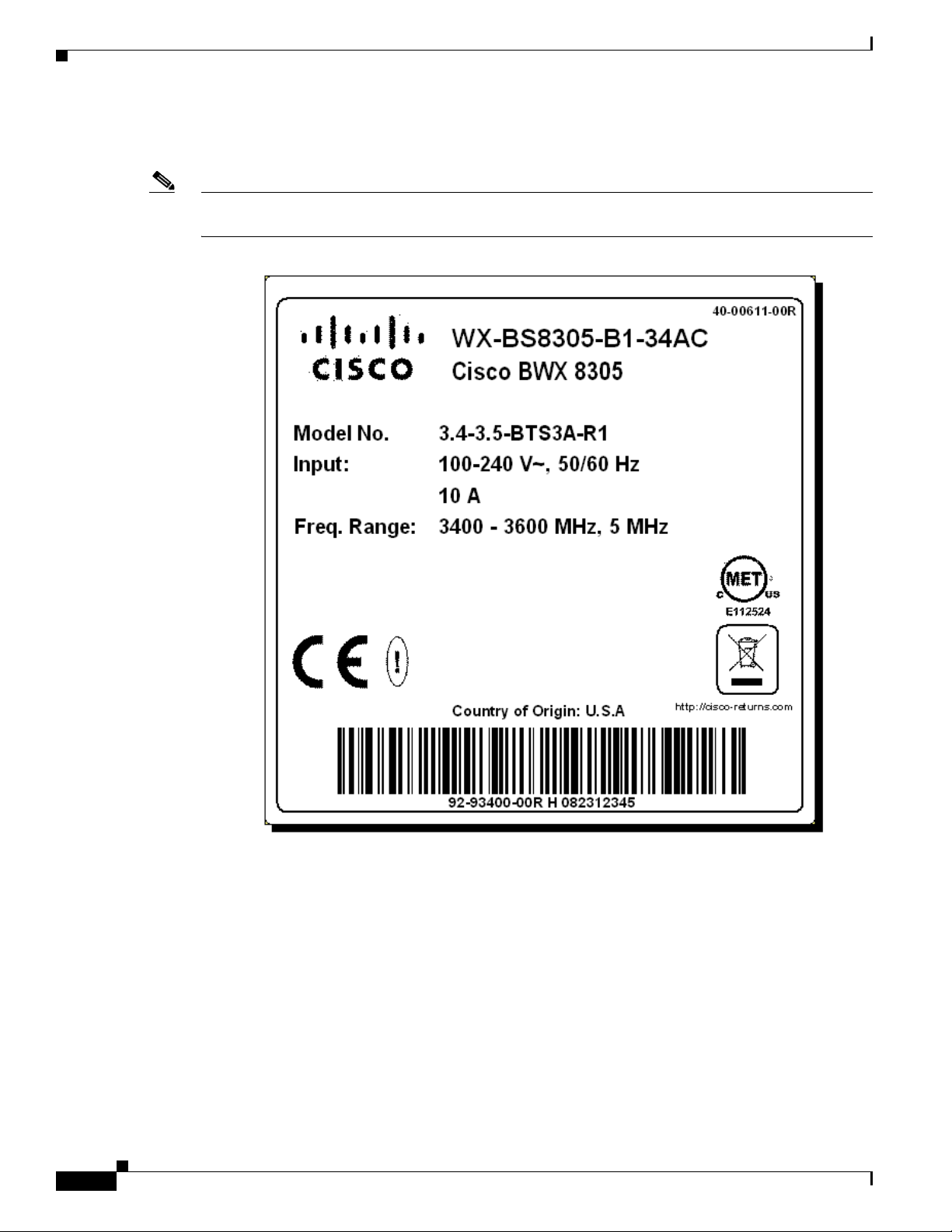
This is an example of the regulatory label affixed to the bottom of each BS unit. It provides identification
information and appropriate regulatory approvals for that unit.
Note The professional installer may want to inspect the labels before installation, as thereafter his view of
them may be obstructed. The information on the label is to be entered in the Closeout Tool.
2-2
BWX 8305 Basestation Installation and Commissioning Guide
OL-16336-02
Page 17

Overview
3.1 Scope of this Guide
This document was created specifically for the BWX 8305 Basestation (BS), which allows Service
Providers to service users with Mobile WiMAX technology.
WiMAX is a standards-based, Orthogonal Frequency Division Multiplexing Access (OFDMA)
technology. The procedures in this document are non-frequency specific. This Guide serves as the
instructions for all BWX 8305 BS installations.
3.2 How to Use This Guide
Properly installing and commissioning a BS into commercial operation begins with planning. Cisco
advises skills-certified Installation & Commissioning Technicians to review this entire document and its
referenced material at the beginning of a successful deployment.
Cisco is serious about ensuring your success. In fact, Cisco does not warranty its hardware if the BS has
not been deployed by a Cisco skills-certified Installation & Commissioning Technician. To install and
commission a BS, you will need a standard toolkit, as well as Cisco-specific tools, software,
documentation, and forms that are explained in this guide.
CHA PTER
3
OL-16336-02
Some procedures described in this guide are optional because they depend upon a particular
configuration or Service Provider preference. If you are not certain whether or not you should perform
an optional task, please feel free to contact your account representative or Cisco Technical Assistance
Center (TAC) for assistance. Unless specified as optional, assume the procedure or task must be
completed.
BWX 8305 Basestation Installation and Commissioning Guide
3-1
Page 18

Cisco WiMAX Documentation
3.3 Cisco WiMAX Documentation
Table 3-1 is a complete list of all documents and forms referenced in this guide. Cisco WiMAX
documents are maintained on a LiveLink web page. When you completed your skills
certification/qualification, you should have received your login instructions. If not, please contact the
Cisco BWBU WiMAX Documentation team by emailing
link for access to the appropriate LiveLink web page:
BWBU_Documentation:
https://tools.cisco.com/cws/livelink?func=ll&objid=4353291&objaction=browse
Note that for some components in the WiMAX Profile C configuration, this guide refers to other Cisco
documentation [for example, the Access Services Network Gateway (ASN-GW)]. When those
components are referenced, a link to the
Please make sure you have access to all necessary documentation prior to beginning the installation.
Some documents and forms are software- or hardware-level sensitive. Always ensure you have the
correct version of documents related to the system you are installing.
www.cisco.com site is provided.
Chapter 3 Overview
bwbu-docs@cisco.com. Refer to the following
Ta b l e 3-1 Cisco WiMAX Documentation
Title of Document or Form Where to Find It Cisco Part Number
Release Notes for BWX Mobile WiMAX
Release 7.0
Installation Planning Guide LiveLink Site:
BWBU WiMAX Documentation Roadmap LiveLink Site:
WiMAX RF Planning Guide LiveLink Site:
IP Network Planning Guide LiveLink Site:
VLAN Implementation Guide LiveLink Site:
LiveLink Site:
BWBU_Documentation>Standard
By Request Only Documents>7.0
Standard by Request Documents
BWBU_Documentation>Standard
By Request Only Documents>7.0
Standard by Request Documents
BWBU_Documentation>
STANDARD_DOCS>7.0 Standard
Documents
BWBU_Documentation>Standard
By Request Only Documents>7.0
Standard by Request Documents
BWBU_Documentation>Standard
By Request Only Documents>7.0
Standard by Request Documents
BWBU_Documentation>Standard
By Request Only Documents>7.0
Standard by Request Documents
OL-17836-01
OL-16328-02
OL-18211-01
OL-16333-02
OL-16329-02
OL-16314-02
3-2
BWX 8305 Basestation Installation and Commissioning Guide
OL-16336-02
Page 19

Chapter 3 Overview
Cisco WiMAX Documentation
Table 3-1 Cisco WiMAX Documentation
Title of Document or Form Where to Find It Cisco Part Number
BWX Mobile WiMAX Migration Planning
Guide
LiveLink Site:
BWBU_Documentation>Standard
OL-16311-02
By Request Only Documents>7.0
Standard by Request Documents
BWX Mobile WiMAX Overview Manual LiveLink Site:
BWBU_Documentation>
OL-16317-02
STANDARD_DOCS>7.0 Standard
Documents
BWX Mobile WiMAX Configuration Guide LiveLink Site:
OL-16313-02
BWBU_Documentation>Standard
By Request Only Documents>7.0
Standard by Request Documents
Configuring WiMAX Subscriber Stations
Using Cisco Access Registrar (CAR)
LiveLink Site:
BWBU_Documentation>Standard
OL-17837-01
By Request Only Documents>7.0
Standard by Request Documents
BWX EMS Software Installation Guide LiveLink Site:
OL-16309-02
BWBU_Documentation>Standard
By Request Only Documents>7.0
Standard by Request Documents
BWX EMS Config CLI Reference Manual LiveLink Site:
OL-16306-02
BWBU_Documentation>Standard
By Request Only Documents>7.0
Standard by Request Documents
BWX EMS Overview Manual LiveLink Site:
BWBU_Documentation>
OL-16308-02
STANDARD_DOCS>7.0 Standard
Documents
BWX EMS Alarm Resolution Reference
Manual
LiveLink Site:
BWBU_Documentation>Standard
OL-16305-02
By Request Only Documents>7.0
Standard by Request Documents
BWX EMS Diagnostic Tools Guide LiveLink Site:
OL-16307-02
BWBU_Documentation>Standard
By Request Only Documents>7.0
Standard by Request Documents
BWX 110 Desktop Modem User Guide LiveLink Site:
BWBU_Documentation>
OL-16319-02
STANDARD_DOCS>7.0 Standard
Documents
BWX 120 PCMCIA ModemUser Guide LiveLink Site:
BWBU_Documentation>
OL-16321-02
STANDARD_DOCS>7.0 Standard
Documents
OL-16336-02
BWX 8305 Basestation Installation and Commissioning Guide
3-3
Page 20

Cisco WiMAX Documentation
Table 3-1 Cisco WiMAX Documentation
Title of Document or Form Where to Find It Cisco Part Number
BWX 210 Desktop Modem User Guide LiveLink Site:
BWX Modem Diagnostics Tool (NavDiag)
User Guide
BWX 8326 Basestation Combiner User
Guide
Rectifier/Battery Backup Suppliers Appendix A, “Rectifier/Battery
Cisco Recommended Tools Appendix B, “Cisco
RF Coverage Prediction Map Appendix C, “RF Coverage
Site Candidate Evaluation Form LiveLink Site:
RF Center Frequency & Interference
Analysis Guidelines
BWX 8305 Basestation Outdoor Enclosure
Manufacturers
WiMAX I&C Closeout Tool Form &
Procedure
BWBU_Documentation>
STANDARD_DOCS>7.0 Standard
Documents
LiveLink Site:
BWBU_Documentation>TIER 1
& 2 Technical Support Docs>7.0
Tier 1 & 2 Technical Support Docs
LiveLink Site:
BWBU_Documentation>TIER 1
Installation & Commissioning
Docs>7.0 Tier 1 Installation &
Commissioning Docs
Backup Suppliers”
Recommended Tools”
Prediction Map Example”
BWBU_Documentation>TIER 1
Installation & Commissioning
Docs>7.0 Tier 1 Installation &
Commissioning Docs
Copy of front sheet shown in
Appendix D, “Site Candidate
Evaluation Form”
Appendix E, “RF Center
Frequency & Interference Analysis
Guidelines”
Appendix F, “BWX 8305
Basestation Outdoor Enclosure
Manufacturers”
LiveLink Site:
BWBU_Documentation>TIER 1
Installation & Commissioning
Docs>7.0 Tier 1 Installation &
Commissioning Docs
Chapter 3 Overview
OL-16322-02
OL-17840-02
OL-16336-02
OL-16336-02
OL-16336-02
OL-16336-02
OL-16336-02
OL-16336-02
OL-16336-02
OL-16336-02
3-4
TTA Channel Filter Installation Procedure Appendix H, “BWX Antenna
BWX 8305 Basestation Installation and Commissioning Guide
Copy of front sheet shown in
Appendix G, “Closeout Tool Form
& Procedure”
OL-16336-02
Channel Filter Installation
Procedure”
OL-16336-02
Page 21

Chapter 3 Overview
Table 3-1 Cisco WiMAX Documentation
Title of Document or Form Where to Find It Cisco Part Number
Guidelines for Painting Cisco Antenna Appendix I, “Guidelines for
Painting a Cisco Antenna”
High-Powered BWX Basestation Antenna Appendix J, “High-Powered BWX
Basestation Antenna”
Software Upgrade Procedures Appendix L, “Software Upgrade
Procedures (Example)”
3.4 BWX 8305 Basestation Components
A Cisco BWX Mobile WiMAX system provides wireless broadband access to a core network, typically
to the Internet or to any local or wide area network (LAN/WAN). When a Service Provider has
established BSs in a given coverage area, the subscriber connects a BWX 110 or BWX 210 Desktop
Modem to their computer (or inserts a BWX 120 PCMCIA Modem into their laptop) to access the
network without the need for a professional installer.
This is what Cisco refers to when it says its system is “zero-install®”: no truck rolls, no professional
installation schedule for the consumer. In fact, some Service Providers have their subscribers pick up
their Modems at retail stores, or, in some cases, simply mail the Modems to the subscribers. The
subscriber Modem is generally referred to as Subscriber Station(SS). The SSs can be Desktop Modems
that attach via an Ethernet cable to the user’s PC, or they can be Wireless PC Cards that insert in the
PCMCIA slot on a laptop computer.
BWX 8305 Basestation Components
OL-16336-02
OL-16336-02
OL-16336-02
In Release 7.0 Cisco offers three Subscriber Stations: the BWX 110 Desktop Modem, the BWX 210
Desktop Modem, and the BWX120 PCMCIA Modem Card. The BWX 110 Desktop Modem covers a 2
MHz frequency range and comes with a Liquid-crystal Display (LCD) front panel, that shows signal
status, while the BWX 210 Desktop Modem covers a 5 MHz frequency range, has no LCD display and
is simply switched on/off. The BWX 120 PCMCIA plugs into laptops for true portability to change
locations easily, where coverage is available.
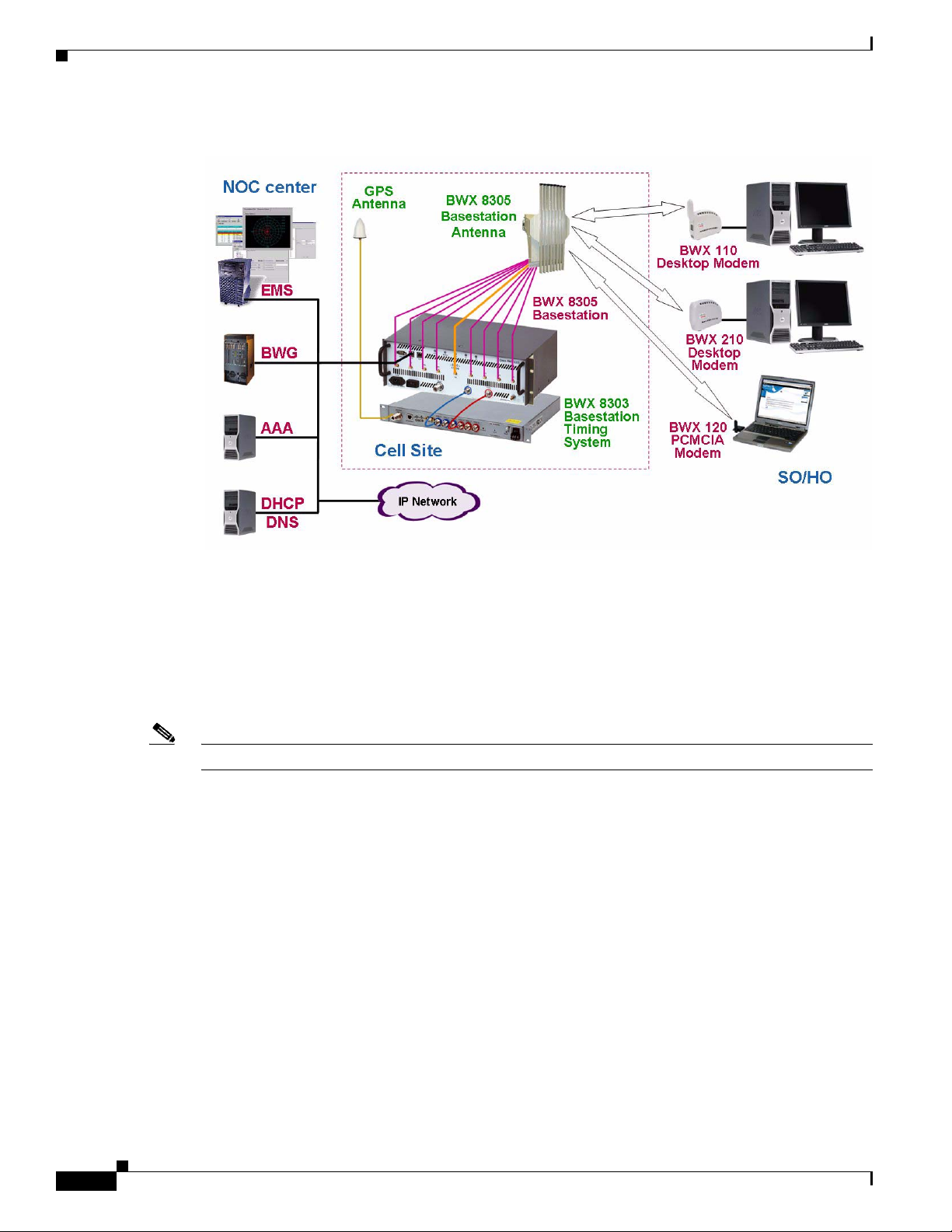
The entire BWX Mobile WiMAX system (Figure 3-1) has four main components: one or more
Basestations, Subscriber Stations (SSs, also referred to as Modems), the Element Management System
(EMS), and the Broadband Wireless Gateway (BWG). The BS portion of the system consists of the BWX
8305 Basestation, BWX 8303 Basestation Timing System, and the BWX Basestation Antenna.
OL-16336-02
BWX 8305 Basestation Installation and Commissioning Guide
3-5
Page 22
BWX 8305 Basestation Components
Figure 3-1 BWX Mobilw WiMAX System Components
Chapter 3 Overview
The BS performs the conversion of RF signals to digital signals for packets transmitted uplink (SS to
BS), and converts digital signals to RF signals transmitted downlink (BS to SS). The BS interfaces with
the BWG and either directs traffic to/from the BWG (residential service) or tags the traffic to route
to/from a private network (Business/Enterprise service). The BWX Antenna is the antenna that is
mounted on a tower, rooftop, or other structure. The BS is available as a BWX 8305 Basestation or as a
BWX 2305 Basestation. The BWX 8305 has an BWX Antenna with 8 antenna elements, while the BWX
2305 has 2 individual dipole antennas.
Note The BWX 8303 Basestation Timing System is required for WiMAX Basestations.
The BS uses a Global Positioning System (GPS) antenna, connected to a BWX 8303 Basestation Timing
unit. The BWX 8303 Basestation Timing System (formerly known as External GPS Unit, EGU) is
mandatory for BSs in all WiMAX deployments starting with Release 7.0 and subsequent releases.
For network deployments, the BS with BWX 8303 Basestation Timing System is the only supported
configuration in WiMAX deployments for Release 7.0 and subsequent upgrades. Warranty and ongoing
TAC support on the BS only covers BSs deployed with the supported configuration. Existing customers
having BSs deployed with built-in GPS must order and install the BWX 8303 Basestation Timing
System as a prerequisite prior to performing software upgrade to Release 7.0 and subsequent
releases. One BWX 8303 Basestation Timing System supports up to three BSs at a cell site. Installation
of the BWX 8303 Basestation Timing System must be performed by qualified personnel to preserve
warranty for the BS at the same site.
For WiMAX deployments, an accurate timing system as the source of synchronization is a requirement for
the BS to function properly. The BWX 8303 Basestation Timing System provides this timing source to the
BS.
The maximum throughput varies by Model type and RF channel conditions.
3-6
BWX 8305 Basestation Installation and Commissioning Guide
OL-16336-02
Page 23
Chapter 3 Overview
The EMS is a set of software applications that the Service Provider uses to configure, communicate with,
and manage all the system elements directly related to the Broadband Wireless Access system. EMS
provides a single point for managing BWG-toBS, BWG-to-EMS, BS, and SS communications in a
WiMAX network.
The EMS is an IP-based element manager designed in a Server-Client relationship and runs on either
Windows or Solaris Operating Systems. Most Service Providers use the Client EMS Configuration &
Alarm Manager (CAM) application to interface with the system. All of the functions that can be
performed through the CAM can also be performed through a Command Line Interface (CLI), which is
a common computing language across platforms.
3.5 Beamforming
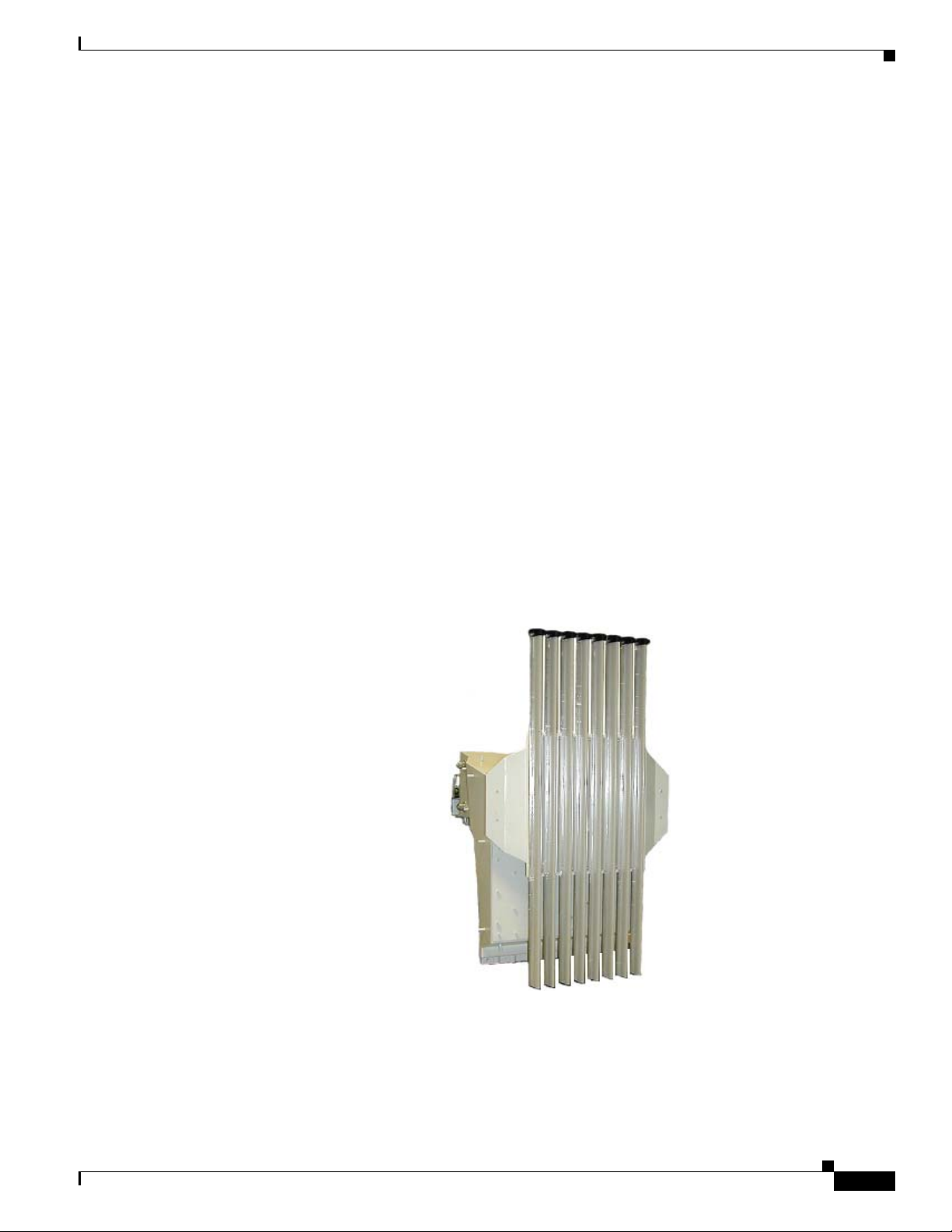
Cisco BWX 8305 Basestation antennas contain 8 elements (Figure 3-2), with a gain of 16 dB in the panel
configuration. Their combined effect is to concentrate the downlink data into a beam with maximum gain
at the location of each target SS (
Similarly, in the uplink the data transmitted by each SS is received by the 8 antenna elements with
different phases due to the differences in propagation distance from an SS to each antenna element. The
contributions from an SS are added up coherently after adjusting their phases for maximum gain. This
effect, which we call beamforming, is equivalent to having up to 18 dB of additional gain in the downlink
and up to 9 dB additional gain in the uplink. It allows the Cisco BWX Mobile WiMAX system to ate at
a much lower power level than would otherwise be necessary for the same results.
Beamforming
Figure 3-3).
Figure 3-2 BWX 8305 Basestation Antenna
OL-16336-02
BWX 8305 Basestation Installation and Commissioning Guide
3-7
Page 24
Beamforming
Chapter 3 Overview
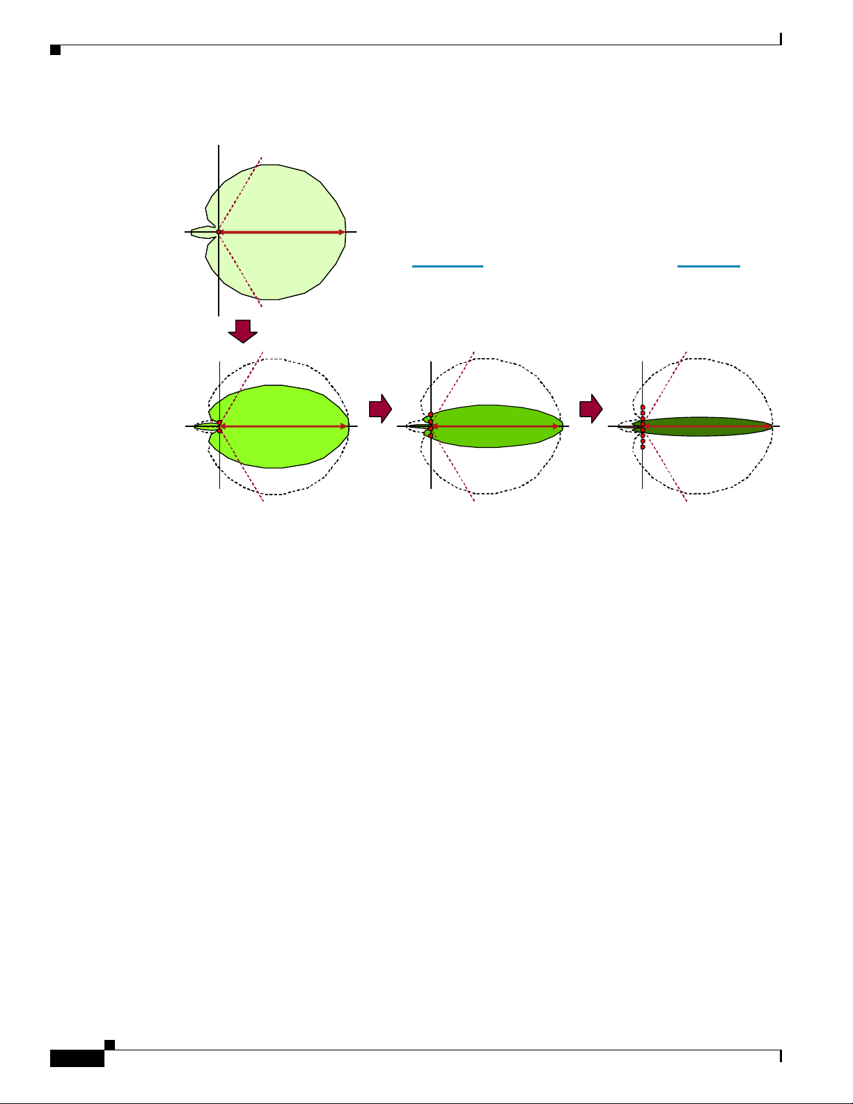
Figure 3-3 Beamforming
The phase of the individual elements is
controlled so that their contributions to the
EM field add up constructively (thus
concentrating the power of the beam) in a
particular direction
Concentrate the beam × 2
Concentrate the beam × 2Concentrate the beam × 2
Concentrate the beam × 2 Concentrate the beam × 2
Concentrate the beam × 2 Concentrate the beam × 2Concentrate the beam × 2 Concentrate the beam × 2
Doubling
the number of elements doubles
the concentration of the beam
Our antennas have 2 × 2 × 2 = 8 elements
3 + 3 + 3 = 9 dB of gain
3-8
BWX 8305 Basestation Installation and Commissioning Guide
OL-16336-02
Page 25
I&C Process
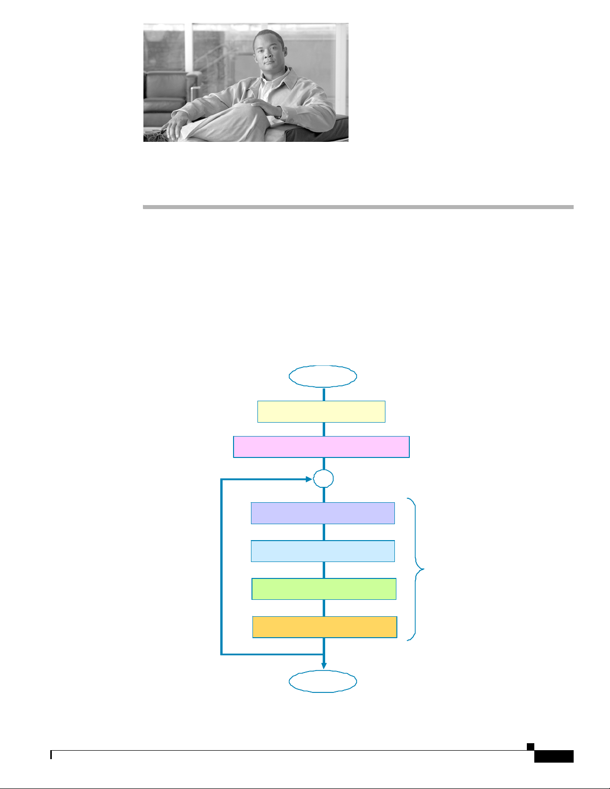
4.1 The Big Picture
The BWX 8305 Basestation installation and commissioning process begins well before equipment is
ever shipped and unpacked. This chapter gives you some perspective of all the activities that take place
before, during, and after a site is installed. While each company, each network, and each site may be
different, the general process described in the flowcharts that follow has been utilized in many successful
deployments. Review each chart carefully, referring to the designated reference material and forms
provided by Cisco.
CHA PTER
Start
Start
Pla nni ng & Prep ar at ion
Pla nni ng & Prep ar at ion
4
Pre- Co n figur ation (EMS & SSs )
Pre- Co n figur ation (EMS & SSs )
Pre-installation
Pre-installation
On site (Installation)
On site (Installation)
On Site (Commissioning)
On Site (Commissioning)
Cut-Ov er
Cut-Ov er
End
End
For eac h B S
For eac h B S
OL-16336-02
BWX 8305 Basestation Installation and Commissioning Guide
4-1
Page 26

Planning, Preparation and Pre-Configuration
4.2 Planning, Preparation and Pre-Configuration
Plan ning & Preparation Pre-Configuration
Start
Start
Complete Project Plan
Complete Project Plan
(Progra m or P roje c t M a nager)
(Progra m or P roje c t M a nager)
Generate the
Generate the
RF coverage prediction map
RF coverage prediction map
(RF Engineer)
(RF Engineer)
Conduct site survey &
Conduct site survey &
complete the Si t e Candida t e
complete the Si t e Candida t e
Ev al u ation Form
Ev al u ation Form
Complete the
Complete the
Interference Analysis
Interference Analysis
Chapter 4 I&C Process
Install & configure
Install & configure
the “production”
the “production”
EMS Serv er & Client
EMS Serv er & Client
If not already in place
If not already in place
Install & configure
Install & configure
the ‘test’
the ‘test’
EMS Serv er & Client
EMS Serv er & Client
on your laptop
on your laptop
Add ad ditio nal Global C onf ig
Add ad ditio nal Global C onf ig
param ete r s as required by your
param ete r s as required by your
company (if needed)
company (if needed)
Complete the Site Design
Complete the Site Design
(Site Planner)
(Site Planner)
Complete the
Complete the
Complete the
Complete the
Network Architecture des ign
Network Architecture des ign
Network Architecture des ign
Network Architecture des ign
N etw ork Pla nni ng)
(Net w ork P la nne r)
N etw ork Pla nni ng)
(Net w ork P la nne r)
Select which cables to use
Select which cables to use
(RF , CAL and GPS)
(RF , CAL and GPS)
Develop the Bill of Materials.
Develop the Bill of Materials.
Acquire all equipment, materials,
Acquire all equipment, materials,
documents, and forms
documents, and forms
Add & configure a record
Add & configure a record
for each CPE to be used during
for each CPE to be used during
t h e co mmis sioning te st s.
t h e co mmis sioning te st s.
A
A
THE INSTAL LER WILL DO
THE INSTAL LER WILL DO
ALL THE FOLLO WING
ALL THE FOLLO WING
TA SK S US ING T HE TEST
TA SK S US ING T HE TEST
EMS. THEN , WHEN THE BS
EMS. THEN , WHEN THE BS
IS UP AND RUN NING AND
IS UP AND RUN NING AND
ALL THE T ESTS HAVE BEEN
ALL THE T ESTS HAVE BEEN
COMPLETE D, THE BS IS
COMPLETE D, THE BS IS
“CUT OVER” TO THE
“CUT OVER” TO THE
PRODUCTION EMS
PRODUCTION EMS
4-2
BWX 8305 Basestation Installation and Commissioning Guide
OL-16336-02
Page 27

Chapter 4 I&C Process
4.3 Pre-installation
Pre-Installation – (for each BS, prior to cell site installation)
A
Obtain BS-specific inf ormation:
(BTS ID, Name, IP address,
Subnet mask, Gateway IP,
Antenna Pow er, RX Sensitivity,
(Azim ut h, til t, elev ation, etc.)
,etc.)
Obtain Ant enna-s pecific
information:
In the Test EMS,
add and config ure
a BWG Record
In the Test EMS,
add and config ure
a BS Record
E dit and run the RFS script
Confirm mounting rac k or
ou tdoo r en c l os u re av a ilabilit y
Confirm that t he
input pow er and ground i ng
ar e installed and read y
Confirm the cus tomer back haul
netwo rk ava ilability at the site
Pre-installation
AT THIS POINT THE RECORD
I S READY TO BE ASSI GN ED
T O A REAL BS
Conf irm that BS, Antenna,
cabl es, etc. have been deliv er ed to
the cell site
B
OL-16336-02
BWX 8305 Basestation Installation and Commissioning Guide
4-3
Page 28

Installation
4.4 Installation
Check cont ent of boxe s.
Check cont ent of boxe s.
Make sure nothing is missing
Make sure nothing is missing
Check that the Antenn a has a
Check that the Antenn a has a
printed sheet with losses
printed sheet with losses
measured in the lab and a CD with
measured in the lab and a CD with
the RFS electrical parameters
the RFS electrical parameters
S w eep the bundled and jumper
S w eep the bundled and jumper
cables and co mpa re with the value
cables and co mpa re with the value
in the factory labe l. Enter the total
in the factory labe l. Enter the total
from the factory labels in the
from the factory labels in the
Closeout Tool Æ Ca ble Loss tab
Closeout Tool Æ Ca ble Loss tab
Sweep the Antenna and compare
Sweep the Antenna and compare
with the values in the printed
with the values in the printed
sheet. Enter the measur ed results
sheet. Enter the measur ed results
top half of the Closeout T ool Æ
top half of the Closeout T ool Æ
RFS & RFS Cable Loss tab
RFS & RFS Cable Loss tab
Mount the Ant enna on the tower,
Mount the Ant enna on the tower,
building, or other s tructure,
building, or other s tructure,
and ground it.
and ground it.
Install surge protectors
Install surge protectors
in the Antenna
in the Antenna
Connect the Main cables to the
Connect the Main cables to the
surge prot ectors at the Antenna
surge prot ectors at the Antenna
Instal l the lower bus bar
Instal l the lower bus bar
with surge protectors
with surge protectors
Connect the Main cables from
Connect the Main cables from
the Ant enna to the lower bus bar
the Ant enna to the lower bus bar
B
B
in the
in the
Chapter 4 I&C Process
Installation – (for each BS at the cell site)
If using a combin er, sweep it to
If using a combin er, sweep it to
determine the associa ted insertion
determine the associa ted insertion
Install and connec t Com biner.
Install and connec t Com biner.
Sweep the Antenna and the cables
Sweep the Antenna and the cables
together and ent er the measured
together and ent er the measured
results in the bot tom half of the
results in the bot tom half of the
Clo s e out Tool Æ RF S & RFS
Clo s e out Tool Æ RF S & RFS
Connect t he 9 jumper cables from
Connect t he 9 jumper cables from
the lower Bus bar to the front of the
the lower Bus bar to the front of the
BS (either dire ctly or through the
BS (either dire ctly or through the
Mount the BWX 8303 Basestation
Mount the BWX 8303 Basestation
Timing Sy stem in the rack and
Timing Sy stem in the rack and
Verify all the BS cables are
Verify all the BS cables are
loss.
loss.
Cable Loss tab
Cable Loss tab
Install the BS unit in the
Install the BS unit in the
mounting rac k or outdoor
mounting rac k or outdoor
enclosure and ground it
enclosure and ground it
combiner)
combiner)
Swe ep the GPS cable.
Swe ep the GPS cable.
Insta ll the GPS antenna
Insta ll the GPS antenna
Connect the GPS cable
Connect the GPS cable
to the GPS antenna and
to the GPS antenna and
to the surge protector
to the surge protector
in the lower Bus bar
in the lower Bus bar
ground it
ground it
properly connected and
properly connected and
weatherproofed
weatherproofed
Connect the B S, BWX 8303, BWG,
Connect the B S, BWX 8303, BWG,
and Server to an Ethernet Switch
and Server to an Ethernet Switch
Verify the BWX 8303 perform anc e
Verify the BWX 8303 perform anc e
Verify access to a AAA server
Verify access to a AAA server
Verify access to a DHCP server for
Verify access to a DHCP server for
the BS Data port to the installer’s
the BS Data port to the installer’s
Connect the console port of the BS
Connect the console port of the BS
to the serial port of the Installer’s
to the serial port of the Installer’s
NOW YOU CAN POWER UP
NOW YOU CAN POWER UP
Check t he power voltage
Check t he power voltage
and connect the BS, BWG,
and connect the BS, BWG,
and BWX 8303 to power
and BWX 8303 to power
(Pow er up a nd l oc k i n)
(Pow er up a nd l oc k i n)
Mount BWG unit
Mount BWG unit
And boot up
And boot up
IP addressing
IP addressing
To r un Te st EMS ,
To r un Te st EMS ,
use two strai ght through
use two strai ght through
E the rnet cables to connect
E the rnet cables to connect
laptop through th e
laptop through th e
Ethernet switch
Ethernet switch
laptop and start a Terminal
laptop and start a Terminal
Emulation w indow
Emulation w indow
C
C
THE BS FOR THE INITIAL
THE BS FOR THE INITIAL
BOOT!!!
BOOT!!!
4-4
BWX 8305 Basestation Installation and Commissioning Guide
OL-16336-02
Page 29

Chapter 4 I&C Process
4.5 Commissioning
Commission ing – (for each BS at the cell site)
C
C
Power up the BS.
Power up the BS.
Change the boot -line parameters
Change the boot -line parameters
to p o i nt to the B S r e cord i n th e
to p o i nt to the B S r e cord i n th e
Test EMS.
Test EMS.
Resume the boot
Resume the boot
W a i t 5 mi n a fter b o ot completes.
W a i t 5 mi n a fter b o ot completes.
Make sure that there are no
Make sure that there are no
outstanding alarms and that the BS
outstanding alarms and that the BS
is stable (not res etting)
is stable (not res etting)
Perform 3 full calibrat io ns
Perform 3 full calibrat io ns
Perf orm th e Loc at ion Test
Perf orm th e Loc at ion Test
and the Single Antenna
and the Single Antenna
Eleme nt te st
Eleme nt te st
If
If
not succe ssfu l ,
not succe ssfu l ,
troubleshoot,
troubleshoot,
recalibrate and
recalibrate and
repeat
repeat
Y
Y
Perform the Drive Tes t
Perform the Drive Tes t
Complete the I&C Closeout Tool
Complete the I&C Closeout Tool
Commissioning
N
N
If not successful,
If not successful,
troubleshoot
troubleshoot
and repea t
and repea t
Y
Pe rfor m the RF Verif ic ation
Pe rfor m the RF Verif ic ation
Y
If not successful,
If not successful,
troubleshoot
troubleshoot
and repea t
and repea t
Y
Y
N
N
N
N
Gather all the Closeo ut
Gather all the Closeo ut
documentation files and zip them
documentation files and zip them
Take pictures
Take pictures
Gather all the Closeo ut
Gather all the Closeo ut
documentation files and zip them
documentation files and zip them
to Operator
to Operator
D
D
NOW YOU CAN CUT THE BS
NOW YOU CAN CUT THE BS
OVER TO THE PRODUCTION
OVER TO THE PRODUCTION
EMS
EMS
OL-16336-02
BWX 8305 Basestation Installation and Commissioning Guide
4-5
Page 30

Cut-Over
4.6 Cut-Over
D
D
In the Test EMS ,
In the Test EMS ,
In the Test EMS ,
export the BS record
export the BS record
export the BS record
(B T S D at a Ex port )
(B T S D at a Ex port )
(B T S D at a Ex port )
Copy this
Copy this
Copy this
BTS Data Export rec ord
BTS Data Export rec ord
BTS Data Export rec ord
ton t he comput er where the
ton t he comput er where the
ton t he comput er where the
Production EMS was installed
Production EMS was installed
Production EMS was installed
In the Production EMS,
In the Production EMS,
In the Production EMS,
import the BS record
import the BS record
import the BS record
(BTS Data Import)
(BTS Data Import)
(BTS Data Import)
Cut-Over
Connec t the Da ta port of the BS
Connec t the Da ta port of the BS
Connec t the Da ta port of the BS
Connec t the Da ta port of the BS
directly to the Ethernet backhaul
directly to the Ethernet backhaul
directly to the Ethernet backhaul
directly to the Ethernet backhaul
Connec t th e consol e port of the BS
Connec t th e consol e port of the BS
Connec t th e consol e port of the BS
Connec t th e consol e port of the BS
to the seri al port of the Installer’s
to the seri al port of the Installer’s
to the seri al port of the Installer’s
to the seri al port of the Installer’s
laptop and start a Terminal
laptop and start a Terminal
laptop and start a Terminal
laptop and start a Terminal
Emulat io n w in dow
Emulat io n w in dow
Emulat io n w in dow
Emulat io n w in dow
Power up the BS.
Power up the BS.
Power up the BS.
Power up the BS.
Change the boot-l ine param et e rs
Change the boot-l ine param et e rs
Change the boot-l ine param et e rs
Change the boot-l ine param et e rs
to poi nt to the BS rec or d in the
to poi nt to the BS rec or d in the
to poi nt to the BS rec or d in the
to poi nt to the BS rec or d in the
ProductionEMS.
ProductionEMS.
ProductionEMS.
ProductionEMS.
Res um e the boot
Res um e the boot
Res um e the boot
Res um e the boot
Chapter 4 I&C Process
Edit the BS record
Edit the BS record
Edit the BS record
( Chan g e th e EMS IP, BT S IP,
( Chan g e th e EMS IP, BT S IP,
( Chan g e th e EMS IP, BT S IP,
subnet mask, and gateway IP
subnet mask, and gateway IP
subnet mask, and gateway IP
to the correct value for the
to the correct value for the
to the correct value for the
Prod uction EM S)
Prod uction EM S)
Prod uction EM S)
F ro m the Produc ti o n EM S ,
F ro m the Produc ti o n EM S ,
F ro m the Produc ti o n EM S ,
F ro m the Produc ti o n EM S ,
Calibrat e the BS
Calibrat e the BS
Calibrat e the BS
Calibrat e the BS
B ackup the Produc t ion E M S
B ackup the Produc t ion E M S
B ackup the Produc t ion E M S
B ackup the Produc t ion E M S
End
End
End
4-6
BWX 8305 Basestation Installation and Commissioning Guide
OL-16336-02
Page 31

Pre-installation
5.1 Personnel & Tools
Reference: Appendix B, “Cisco Recommended Tools”
The BWX 8305 Basestation (BS) equipment installation itself normally takes 1-2 people only 2 days1.
However, prior to installing the equipment a number of planning, acquisition, and other preparation
activities take place. If these tasks are not completed before the installers show up to begin installing,
then the deployment may take longer than 2 days. The planning tasks are not detailed in this guide, but
information or examples for many of them are referenced and located in the appendices.
5.2 Project Plan
Cisco provides several options to customers for the work to be done in preparing a site for operation.
The customer may have their own installation personnel, or they may hire Cisco or one of its authorized
service partners to perform the installation. A project plan document that lays out the work to be done,
the objectives of the project, the schedule, the resources required to complete it, and other information
pertinent to the deployment needs to be developed.
CHA PTER
5
5.3 RF Coverage Prediction Map
Reference:
• Appendix C, “RF Coverage Prediction Map Example”
• RF Sales Guide P/N: OL-16330-01
• WiMAX RF Planning Guide P/N: OL-16333-02
As part of determining which BS equipment is needed and where to place the equipment for a successful
deployment, an RF Engineer (customer’s, Cisco’s, or service partner’s) will go through the process of
studying the RF environment of the candidate sites that the Service Provider has identified. The RF
Engineer takes readings and analyzes each site in order to predict what range of coverage may be
expected. Coverage predictions take into account Basestation performance capabilities and the Service
Provider’s marketing objectives. An example is shown in
Example.”
1. All I&C tasks can be completed by 1 person, but 2 may be desired during commissioning - one to drive and
one to run the tests using a laptop computer.
OL-16336-02
Appendix C, “RF Coverage Prediction Map
BWX 8305 Basestation Installation and Commissioning Guide
5-1
Page 32

Site Candidate Evaluation
5.4 Site Candidate Evaluation
Reference: Appendix D, “Site Candidate Evaluation Form”
As various deployment sites are being considered, most companies use a form like the one Cisco calls
the Site Candidate Evaluation form. The form, when completed properly, helps to ensure that all aspects
of planning for the site have been considered. Every site is unique, and the form is filled out for each
site. Doing this makes sure nothing is taken for granted or assumed about the site and whether or not it
will be a successful deployment site if selected.
Cisco provides the Site Candidate Evaluation form in electronic format. The form includes fields to
capture the logistics of the site, GPS coordinates, antenna mount possibilities, power availability, etc. It
is from this information that a selected site will be planned and prepared for equipment installation and
connections. The main page of the form is displayed in
This form can be found on the following LiveLink site:
https://tools.cisco.com/cws/livelink?func=ll&objid=4353291&objaction=browse.
5.5 Interference Analysis
Chapter 5 Pre-installation
Appendix D, “Site Candidate Evaluation Form.”
Reference: Appendix E, “RF Center Frequency & Interference Analysis Guidelines”
Cisco recommends to Service Providers that they conduct an Interference Analysis of the selected site.
The Interference Analysis is performed primarily to assure there is no other radiating equipment in the
geographical area that might interfere with the BS operation.
5.6 Site Design & Regulatory
The site where the BS is going to be installed must be carefully blueprinted to prepare for equipment
ordering and installation. Cisco can supply product specifications and drawings to help the customer
design the site. More importantly, however, is that the Service Provider of any wireless equipment must
be versed in the regulatory requirements for the region. Unless operating in an unlicensed frequency,
such as 2.4 GHz, the Service Provider must have a spectrum license (usually from a government
regulatory body). The Service Provider is also responsible to see that communications and other
regulatory standards and laws will be sufficiently met at this site.
Note WiMAX does not operate in unlicensed bands.
5.7 Network Architecture Plan
Reference: IP Network Planning Guide P/N: OL-16329-01
The Service Providers Network Administrator or Planner is involved with a deployment from the
perspective of integrating the BS, BWG, and AAA seamlessly into the operational network. They have
to plan the traffic routing, IP addressing, protocol compatibility, and how they are going to monitor BS,
BWG, and AAA operation.
5-2
BWX 8305 Basestation Installation and Commissioning Guide
OL-16336-02
Page 33

Chapter 5 Pre-installation
5.8 RF Cable Selection
The size and type of cables used to install the Basestation affect power loss and calibration range for the
transmitter and receiver. The Service Provider must decide which type of cable and connectors they will
need and get them ordered. Cisco offers a limited number of cable types & lengths. Service Providers
who have cable needs, not offered by Cisco, can purchase these cables form a Cisco approved supplier
(Contact your Account Manager for further details). No matter which are chosen, all cables and
connectors must meet FCC or other regulatory limits for RF, UL, and NEC/CEC. Selection guidelines
are provided by Cisco based upon the frequency band and the length of the cable required between the
BS and BWX 8305 Basestation antenna.
Note Use of non-Cisco approved cables can invalidate the warranty.
5.9 Bill of Materials (BoM)
Whoever orders the equipment must generate the Bill of Materials (BoM), which is the actual equipment
order for manufacturing and shipping to the installation site. Cisco provides the part number and prices,
as well as recommendations to assist customers in the correct placement of orders. Normally, the
customer will work with their Cisco Account Manager or Cisco authorized partner to complete the BoM.
RF Cable Selection
5.10 Acquire Materials, Documents & Forms
Once ordered, the purchaser has to ensure that everything required for the installation is secured and at
the deployment site. Cisco highly recommends inventorying the equipment arrival prior to having
installers brought on-site so that they do not have to wait on parts to complete the installation. Also make
sure that all necessary documents and forms that are referenced in this guide are available.
5.11 Confirm AAA, BWG, and Backhaul Network Availability
Verify that the AAA server, BWG, and Backhaul network are all available for connection. The backhaul
connection required for the BS consists of one Ethernet cable connection with RJ-45 connectors for each
BS installed. The exact quantity for each connection will depend on the site requirements. These
connections need to be made available before installation begins. The Service Provider is responsible for
compliance to all regulatory limitations related to the backhaul network and connections.
5.12 Confirm FTP & BWX EMS Server Readiness
The Service Provider should put into place an FTP server and the BWX EMS Server platform prior to
the installation crew’s arrival at site. If the customer’s BWX EMS Server is not available until after
installation begins, the crew will use a laptop to perform initial configuration tasks. The FTP server,
however, must be in place in order to commission the Basestation.
OL-16336-02
BWX 8305 Basestation Installation and Commissioning Guide
5-3
Page 34

Chapter 5 Pre-installation
Confirm Mounting Rack or Outdoor Enclosure Availability
5.13 Confirm Mounting Rack or Outdoor Enclosure Availability
Reference: Appendix F, “BWX 8305 Basestation Outdoor Enclosure Manufacturers”
If the BS will be housed inside a building, it is typically mounted in a standard 19- or 23-inch rack. Rack
adapters are needed to mount the equipment in a standard 23-inch rack. If the BS will be housed
outdoors, the Service Provider must select and make ready an outdoor enclosure. The Service Provider
can supply an outdoor enclosure from any one of a multitude of vendors. Please refer to
“BWX 8305 Basestation Outdoor Enclosure Manufacturers” for recommended manufacturers.
Appendix F,
5.13.1 Accessibility
BS equipment is required to be installed in a restricted access location, in accordance with NEC/CEC
standards. Only authorized personnel should have access to this equipment.
5.14 Confirm Power & Grounding Readiness
The BS can be ordered with one of the following power inputs:
• + 24 VDC
• - 48 VDC
• 100/240, 47/63 Hz VAC
The Service Provider is responsible for providing earth grounding and for meeting all regulatory
standards related to power and grounding.
5.14.1 Power Requirements
Please refer to the Technical Specifications for power requirements. When - 48 VDC or +24 VDC input
power is used, the BS must be connected to a power supply/rectifier that is IEC 60950-1 certified (UL
listed to UL60950-1 in North America) and have a ground SELV output. It must be installed in
accordance with NEC/CEC Articles 800/810/830. A UL listed disconnect device, such as a circuit
breaker or fuse, must be installed between the power supply and the BS chassis connections.
5-4
BWX 8305 Basestation Installation and Commissioning Guide
OL-16336-02
Page 35

Chapter 5 Pre-installation
Note External power source / supply considerations for the - 48V and + 24V BS chassis:
a. An external method of disconnecting each of the DC power Load/Return lines to the BS chassis is
required, either through fuse+disconnect device(s) or a dual-pole breaker. The fuse/breaker rating must
be minimum 10% higher than that of the BS Chassis breaker but shall not exceed 70A.
b. The external DC power source, if current limited, shall have the limit set-point configured higher than
the BS Chassis breaker rating.
c. The external supply "Return" and the BS chassis shall be bonded to a common Earth ground. The BS
Chassis has an external ground lug provided.
d. Do not remove protective earth connection before disconnecting the BS from the DC power supply.
5.14.2 Grounding Requirements
The BS requires an earth ground connection. Grounding from copper point to copper point shall be less
than 1 ohm. Grounding from copper point to earth ground shall be less than 5 ohms. All power and
grounding conductors must be mechanically supported to avoid strain of the wires and connection points.
AWG #6 is used between the equipment and the bus bar, and AWG #2 is required from the bus bar to the
earth ground. Always refer to the regulatory standards for power and grounding.
Confirm Power & Grounding Readiness
5.14.3 Lightning Protection
Every BS automatically comes with Secondary (built-in) lightning protection. The Service Provider
should purchase Primary lightning protection (available from Cisco). Lightning protection helps to
protect the BWX Basestation Antenna, BS, and RF lines against tower lightning events occurring at the
BS. While not absolute, the Primary protection greatly reduces the possibility of damage to the
equipment.
Note Cisco does not warrant equipment damaged by lightning (direct or indirect).
Figure 5-1 below shows a BS with both Primary and Secondary surge protection, which is the
recommended configuration. In addition to tower lightning events occurring at the BS, lightning events
that occur miles away from the BS can generate intense electrical currents traveling over the power
and/or backhaul lines and into the BS equipment, damaging it. For this reason, Cisco strongly
recommends adding the primary surge protection as well as surge protection devices at the power and
backhaul demarcation points.
OL-16336-02
BWX 8305 Basestation Installation and Commissioning Guide
5-5
Page 36

Confirm Power & Grounding Readiness
A
A
A
A
A
A
A
A
A
A
A
A
A
A
A
A
A
A
A
A
A
Figure 5-1 Primary and Secondary Surge Protection Installed
Chapter 5 Pre-installation
Lightning
Lightning
Lightning
Lightning
Lightning
Lightning
Lightning
Lightning
Lightning
Lightning
Lightning
Lightning
Lightning
Lightning
Ground
Ground
Ground
Ground
Ground
Ground
Ground
Ground
Ground
Ground
Ground
Ground
Ground
Ground
Antenna
Antenna
Antenna
Antenna
Antenna
Antenna
Antenna
Antenna
Antenna
Antenna
Antenna
Antenna
Antenna
Antenna
Bracket
Bracket
Bracket
Bracket
Bracket
Bracket
Bracket
Bracket
Bracket
Bracket
Bracket
Bracket
Bracket
Bracket
dditional
dditional
dditional
dditional
dditional
dditional
dditional
dditional
dditional
dditional
dditional
dditional
dditional
dditional
dditional
dditional
dditional
dditional
dditional
dditional
dditional
grounding block
grounding block
grounding block
grounding block
grounding block
grounding block
grounding block
grounding block
grounding block
grounding block
grounding block
grounding block
grounding block
grounding block
grounding block
grounding block
grounding block
grounding block
grounding block
grounding block
grounding block
needed if main
needed if main
needed if main
needed if main
needed if main
needed if main
needed if main
needed if main
needed if main
needed if main
needed if main
needed if main
needed if main
needed if main
needed if main
needed if main
needed if main
needed if main
needed if main
needed if main
needed if main
cable run
cable run
cable run
cable run
cable run
cable run
cable run
cable run
cable run
cable run
cable run
cable run
cable run
cable run
cable run
cable run
cable run
cable run
cable run
cable run
cable run
exceeds 250 ft
exceeds 250 ft
exceeds 250 ft
exceeds 250 ft
exceeds 250 ft
exceeds 250 ft
exceeds 250 ft
exceeds 250 ft
exceeds 250 ft
exceeds 250 ft
exceeds 250 ft
exceeds 250 ft
exceeds 250 ft
exceeds 250 ft
exceeds 250 ft
exceeds 250 ft
exceeds 250 ft
exceeds 250 ft
exceeds 250 ft
exceeds 250 ft
exceeds 250 ft
(75 m)
(75 m)
(75 m)
(75 m)
(75 m)
(75 m)
(75 m)
(75 m)
(75 m)
(75 m)
(75 m)
(75 m)
(75 m)
(75 m)
(75 m)
(75 m)
(75 m)
(75 m)
(75 m)
(75 m)
(75 m)
These are not
These are not
These are not
These are not
These are not
These are not
These are not
These are not
These are not
These are not
These are not
These are not
These are not
These are not
These are not
These are not
These are not
These are not
These are not
These are not
These are not
Surge Protectors
Surge Protectors
Surge Protectors
Surge Protectors
Surge Protectors
Surge Protectors
Surge Protectors
Surge Protectors
Surge Protectors
Surge Protectors
Surge Protectors
Surge Protectors
Surge Protectors
Surge Protectors
Surge Protectors
Surge Protectors
Surge Protectors
Surge Protectors
Surge Protectors
Surge Protectors
Surge Protectors
but N-type/Female
but N-
but N-
but N-
but N-
but N-
but N-
but N-type/Female
but N-
but N-
but N-
but N-
but N-
but N-
but N-type/Female
but N-
but N-
but N-
but N-
but N-
but Nto N-type/Female
to N-
to N-
to N-
to N-
to N-
to N-
to N-type/Female
to N-
to N-
to N-
to N-
to N-
to N-
to N-type/Female
to N-
to N-
to N-
to N-
to N-
to N-
bulkhead
bulkhead
bulkhead
connectors for
connectors for
connectors for
connectors for
connectors for
connectors for
connectors for
connectors for
connectors for
connectors for
connectors for
connectors for
connectors for
connectors for
connectors for
connectors for
connectors for
connectors for
connectors for
connectors for
connectors for
grounding
grounding
grounding
grounding
grounding
grounding
grounding
grounding
grounding
grounding
grounding
grounding
grounding
grounding
grounding
grounding
grounding
grounding
grounding
grounding
grounding
BWX Basestation Antenna
BWX Basestation Antenna
Powe r Ampli fier s
Powe r Ampli fier s
Powe r Ampli fier s
Powe r Ampli fier s
Powe r Ampli fier s
Powe r Ampli fier s
Powe r Ampli fier s
Powe r Ampli fier s
Powe r Ampli fier s
Powe r Ampli fier s
Powe r Ampli fier s
Powe r Ampli fier s
Powe r Ampli fier s
Powe r Ampli fier s
Secondary (Built
Secondary (Built
Secondary (Built – in)
Secondary (Built
Secondary (Built
Secondary (Built – in)
Surge Protectors
Surge Protectors
Surge Protectors
Surge Protectors
Surge Protectors
Surge Protectors
Surge Protectors
Surge Protectors
Dig it a l Sh el f
Dig it a l Sh el f
Dig it a l Sh el f
Dig it a l Sh el f
Dig it a l Sh el f
Dig it a l Sh el f
Dig it a l Sh el f
Dig it a l Sh el f
Dig it a l Sh el f
Dig it a l Sh el f
Dig it a l Sh el f
Dig it a l Sh el f
Dig it a l Sh el f
Dig it a l Sh el f
R ec t if ie r s (2 4 V DC , 60 A )
R ec t if ie r s (2 4 V DC , 60 A )
R ec t if ie r s (2 4 V DC , 60 A )
R ec t if ie r s (2 4 V DC , 60 A )
R ec t if ie r s (2 4 V DC , 60 A )
R ec t if ie r s (2 4 V DC , 60 A )
R ec t if ie r s (2 4 V DC , 60 A )
R ec t if ie r s (2 4 V DC , 60 A )
R ec t if ie r s (2 4 V DC , 60 A )
R ec t if ie r s (2 4 V DC , 60 A )
R ec t if ie r s (2 4 V DC , 60 A )
R ec t if ie r s (2 4 V DC , 60 A )
R ec t if ie r s (2 4 V DC , 60 A )
R ec t if ie r s (2 4 V DC , 60 A )
Frame
Frame
Frame
Frame
Frame
Frame
Frame
Frame
Frame
Frame
Frame
Frame
Frame
Frame
RF
RFRF
CAL
CALCAL
GPS
GPS
GPS
GPS
GPS
GPS
GPS
GPS
GPS
GPS
GPS
GPS
GPS
GPS
GPS
GPS
GPS
GPS
GPS
GPS
Antenna
Antenna
Antenna
Antenna
Antenna
Antenna
Antenna
Antenna
Antenna
Antenna
Antenna
Antenna
Antenna
Antenna
BWX 8303
BWX 8303
Surge Protection Strongly
Option 1 Strongly
Option 1 Strongly
Option 1 Strongly
Option 1 Strongly
Option 1 Strongly
Option 1 Strongly
Option 1 Strongly
Option 1 Strongly
Option 1 Strongly
Option 1 Strongly
Recommended
Re co mmended !
Re co mmended !
Re co mmended !
Re co mmended !
Re co mmended !
Re co mmended !
Re co mmended !
Re co mmended !
Re co mmended !
Re co mmended !
Primary Surge Protectors
Primary Surge Protectors
Primary Surge Protectors
Primary Surge Protectors
Primary Surge Protectors
Primary Surge Protectors
Primary Surge Protectors
Primary Surge Protectors
Primary Surge Protectors
Primary Surge Protectors
Primary Surge Protectors
Primary Surge Protectors
Primary Surge Protectors
Primary Surge Protectors
(Use
(Use
(Use
(Use
(Use
(Use
(Use Polyphas ersurg e p r ot ectors
(Use
(Use
(Use
(Use
(Use
(Use
(Use Polyphas ersurg e p r ot ectors
with the CAL Cable and
with the CAL Cable and
with the CAL Cable and
with the CAL Cable and
with the CAL Cable and
with the CAL Cable and
with the CAL Cable and Huber+ Suhner
with the CAL Cable and
with the CAL Cable and
with the CAL Cable and
with the CAL Cable and
with the CAL Cable and
with the CAL Cable and
with the CAL Cable and Huber+ Suhner
surge protectors everywhere else)
surge protectors everywhere else)
surge protectors everywhere else)
surge protectors everywhere else)
surge protectors everywhere else)
surge protectors everywhere else)
surge protectors everywhere else)
surge protectors everywhere else)
surge protectors everywhere else)
surge protectors everywhere else)
surge protectors everywhere else)
surge protectors everywhere else)
surge protectors everywhere else)
surge protectors everywhere else)
Secondary (Built
Secondary (Built
Secondary (Built – in)
Secondary (Built
Secondary (Built
Secondary (Built – in)
Surge Protectors
Surge Protectors
Surge Protectors
Surge Protectors
Surge Protectors
Surge Protectors
Surge Protectors
Surge Protectors
Surge Protectors
Surge Protectors
Surge Protectors
Surge Protectors
Surge Protectors
Surge Protectors
Use
Use
Use
Use
Use
Use
Use
Use
Use
Use
Use
Use
Use
Use
"Smart J ack"
"Smart J ack"
"Smart J ack"
"Smart J ack"
"Smart J ack"
"Smart J ack"
"Smart J ack"
"Smart J ack"
"Smart J ack"
"Smart J ack"
"Smart J ack"
"Smart J ack"
"Smart J ack"
"Smart J ack"
for surge
for surge
for surge
for surge
for surge
for surge
for surge
for surge
for surge
for surge
for surge
for surge
for surge
for surge
protection!!!
protection!!!
protection!!!
protection!!!
protection!!!
protection!!!
protection!!!
protection!!!
protection!!!
protection!!!
protection!!!
protection!!!
protection!!!
protection!!!
Demarc . P oin ts
Demarc . P oin ts
Demarc . P oin ts
Demarc . P oin ts
Demarc . P oin ts
Demarc . P oin ts
Demarc . P oin ts
Demarc . P oin ts
Demarc . P oin ts
Demarc . P oin ts
Demarc . P oin ts
Demarc . P oin ts
Demarc . P oin ts
Demarc . P oin ts
Rectifier
Rectifier
Rectifier
Rectifier
Rectifier
Rectifier
Rectifier
Rectifier
Rectifier
Rectifier
Rectifier
Rectifier
Rectifier
Rectifier
BWX 8305
BWX 8305 BWX 8305
Ethe rnet
Ethe rnet
Ethe rnet
Ethe rnet
Ethe rnet
Ethe rnet
Ethe rnet
Ethe rnet
Ethe rnet
Ethe rnet
Ethe rnet
Ethe rnet
Ethe rnet
Ethe rnet
110/220 VAC
110/220 VAC
110/220 VAC
110/220 VAC
110/220 VAC
110/220 VAC
110/220 VAC
110/220 VAC
110/220 VAC
110/220 VAC
110/220 VAC
110/220 VAC
110/220 VAC
110/220 VAC
60/50 Hz
60/50 Hz
60/50 Hz
60/50 Hz
60/50 Hz
60/50 Hz
60/50 Hz
60/50 Hz
60/50 Hz
60/50 Hz
60/50 Hz
60/50 Hz
60/50 Hz
60/50 Hz
Surge
Surg e
Surg e
Surg e
Surg e
Surg e
Surg e
Surge
Surge
Surg e
Surg e
Surg e
Surg e
Surg e
Surg e
Protection
Protection
Protection
Protection
Protection
Protection
Protection
Protection
Protection
Protection
Protection
Protection
Protection
Protection
Protection
Device
Device
Device
Device
Device
Device
Device
Device
Device
Device
Device
Device
Device
Device
Device
5 Ohms
Note Cisco does not warrant equipment damaged by lightning (direct or indirect).
5-6
BWX 8305 Basestation Installation and Commissioning Guide
OL-16336-02
Page 37

Installation
6.1 Inventory
Reference: Appendix G, “Closeout Tool Form & Procedure”
The first thing an installer physically does once onsite is to check to see that all equipment and materials
have arrived, as well as to make sure all necessary documents and forms are available. This is when the
installer will first work with the Cisco Closeout Tool by entering the site information for the BS
components. The Closeout Tool is an Excel spreadsheet with linked worksheets and calculations to
automate the system deployment information. The Closeout Tool is explained under the next heading in
this chapter.
Note The installer and/or customer should keep a copy of the collected data/Closeout Tool form for future
reference.
As you inventory the BWX 8305 Basestation (BS) components, check to ensure the following
attachments are visible:
CHA PTER
6
OL-16336-02
• Manufacturing printout sheet attached to the BWX 8305 Basestation Antenna, showing the antenna
insertion loss or gain values in the transmit and receive direction at the lower, middle, and higher
frequencies (
• Compact disk (or other media) attached to BWX 8305 Basestation Antenna (Figure 6-1). It contains
the antenna configuration data specific to that BWX 8305 Basestation Antenna.
• Manufacturing printout sheet attached to the bundled RF cables (RG-6 or RG-11). This sheet
contains the cable loss values for the bundled cable. These values will be entered in the Closeout
Tool. These data are specific to each bundled cable.
Do not try to use former values, i.e., from a previous site, for any of the above three items. Each
measurement is unique to that piece of equipment and must be entered exactly as stated for this
deployment.
Figure 6-1).
BWX 2305 Basestation Installation and Commissioning Guide
6-1
Page 38

WiMAX I&C Closeout Tool
Chapter 6 Installation
Figure 6-1 Printout Sheet & Compact Disk Attached to BWX 8305 Basestation Antenna
6.2 WiMAX I&C Closeout Tool
Reference:
• Appendix G, “Closeout Tool Form & Procedure” or
• WiMAX I&C Closeout Tool & Procedure
The Cisco Closeout Tool is a collection of linked forms with spreadsheet formulas used to capture and
provide important information for each Basestation deployment. The information captured by this tool
is not only used to help verify proper commissioning of the system during acceptance testing of the site,
but it is also used for later troubleshooting if there are problems.
Keep the Closeout Tool open on your computer during the installation and commissioning of the system
(you can minimize). You will mostly be recording data into the green-colored fields in the various
worksheets found in the tool. At this time, select the first worksheet, “Company Info”. Fill in the
company name, BS name, and the remaining green fields (
Regulatory Label attached to the bottom of the BS unit.
Later, you will use the “Read BTS Export File (.txt)” button to populate the yellow fields with BSn
configuration data that is exported from the EMS into a text file. After you complete all of the green
fields, click on “Save Workbook” to save this file. Remember to save the workbook after you make your
entries.
Figure 6-2). Fill in the information from the
6-2
BWX 2305 Basestation Installation and Commissioning Guide
OL-16336-02
Page 39

Chapter 6 Installation
Figure 6-2 Company Info Worksheet
Company Nam e
Site Name
Address
City,State
Zip, Country
Contact In formation
Name
Email Address
Address
City,State
Cou ntry
Phone
BTS ID
BTS Name
BTS Type
Installer Name
Phone
Date
BWX 8305 Basestation Antenna Installation
0
Reset Comp any Info
Site Location
BTS Configuration
Deployment
Read BTS Ex port F i le (*.txt)
40-0 0xxx-x x Rev 1.8 Ve rs ion
Save Workbook
6.3 BWX 8305 Basestation Antenna Installation
Reference:
• Appendix B, “Cisco Recommended Tools”
• Appendix H, “BWX Antenna Channel Filter Installation Procedure”
• Appendix I, “Guidelines for Painting a Cisco Antenna”
Check all regulatory requirements prior to installing the BWX 8305 Basestation Antenna.
6.3.1 Description
The BWX 8305 Basestation Antenna is the part of the BSn that contains the Power Amplifiers (PAs), the
8 antenna elements, and, depending on frequency and customer choice, Channel Filters and Low Noise
Amplifiers (LNAs). A BWX8305 Basestation Antenna radiates 120 degrees (
Channel Filters in a BWX 8305 Basestation Antenna is optional. These filters are installed inside the
BWX 8305 Basestation Antenna, which is shipped separately from the BS.
Figure 6-3). The use of
OL-16336-02
BWX 2305 Basestation Installation and Commissioning Guide
6-3
Page 40

BWX 8305 Basestation Antenna Installation
Chapter 6 Installation
Figure 6-3 BWX 8305 Basestation Antenna
Note The 8 element BWX 8305 Basestation Antenna has 6 degrees of fixed electrical downtilt.
6.3.1.1 Filters
In the BWX 8305 Basestation Antenna you have the option to:
• 1- Use a Band filter:
The Band filter is of the Cavity type. The Channel filter is also of the cavity type but with a Dielectric
Resonant Oscillator (DRO) “puck” placed in the cavity to improve performance. Frequently, the
words “Cavity filter” are used in conjunction with the Band filter.
The functions of the Band filter are two-fold: (1) to shape the out-of-band emission (e.g., L.O.
Linkage, harmonics, and other spurious emissions) during transmission in order to meet Federal
Communications Commission (FCC) or other regulatory requirements; (2) to provide rejection for
close-in interference (e.g., Personal Communication Systems/Advanced Mobile Phone
System(PCS/AMPS) and other cellular services, television (TV), and Radar) during the receive
period (i.e., improve the receiver selectivity). The Band filter has a wider passband than that of a
Channel filter (e.g., BW= 15 MHz separating the Wireless Communications Service (WCS) from
Digital Audio Radio Service (DARS) frequencies).
6-4
BWX 2305 Basestation Installation and Commissioning Guide
OL-16336-02
Page 41

Chapter 6 Installation
Note Depending on the country where the system is being used, a Channel filter or a Band filter or no filter
BWX 8305 Basestation Antenna Installation
• 2- Use a Channel filter:
The functions of Channel filter are two-fold: (1) to shape the power amplifier out-of-band emission
during transmission in order to meet FCC or other regulatory requirements; and (2) to provide high
rejection for close-in jammers during the receive period. The latter improves receiver selectivity. As
indicated by its name, the Channel filter operates in a specific limited frequency band (e.g.,
Bandwidth (BW) = 5 MHz) and has more stringent attenuation requirements. Normally, the
attenuation is 15-20 dB rejection for close-in frequencies.
Additionally, while a Band filter attenuation drop off is slower than that of a Channel filter, it has
much higher attenuation at frequencies removed from the central frequency (e.g., 60 dB).
• 3- Not use a filter at all
If a BWX 8305 Basestation Antenna has Channel Filters installed, it must be operated at a center
frequency that exactly matches the center frequency for which the Channel Filters were manufactured;
otherwise, the equipment could be damaged. If no Channel Filters are installed, the Service Provider is
free to select or change the center frequency of the BS without damaging the equipment.
may be needed to meet the spectrum requirements of that region. In general, the cost associated with a
Channel filter is 3-5 times more than that of a Band filter - a consideration to keep in mind when
addressing a deployment for a specific region.
Note If the Channel Filters do not come installed and you have to install them, please refer to Appendix H,
“BWX Antenna Channel Filter Installation Procedure” for the procedure to do so.
Note If you are required to paint the BWX 8305 Basestation Antenna, for example because of environmental
aesthetics, please refer to Appendix I, “Guidelines for Painting a Cisco Antenna.”
6.3.1.2 High-powered BWX 8305 Basestation Antenna
The High-powered BWX 8305 Basestation Antenna unit operates in the 3475 to 3610 MHz range. This
antenna is intended for use with an BWX 8326 Basestation Combiner unit (which allows 2 Basestations
to share one antenna), but can also be used by a single Basestation to increase capacity. The
High-powered BWX 8305 Basestation Antenna yields 3 dB more than the Standard BWX 8305
Basestation Antenna antenna. See
Appendix J, “High-Powered BWX Basestation Antenna” for more
information on the High-powered BWX 8305 Basestation Antenna, and Appendix K, “BWX 8326
Basestation Combiner (3400 to 3625 MHz)” for information on the BWX 8326 Basestation Combiner
6.3.2 Handling the BWX 8305 Basestation Antenna
It is a good idea to inspect the exterior of the BWX 8305 Basestation Antenna for any damage that may
have occurred during shipping, prior to placing it at the target site. Each of the antenna elements in the
BWX Basestation Antenna are covered by the individual radomes on the panel. At all times handle the
antenna carefully. If, during storage, filter replacement, or PA replacement, you must place a panel
antenna in a position laying down, make sure it rests flat on at least one inch of plastic foam to prevent
damage to the antenna elements.
OL-16336-02
BWX 2305 Basestation Installation and Commissioning Guide
6-5
Page 42

BWX 8305 Basestation Antenna Installation
When you are ready to place the antenna into position, it should be lifted using multiple lift points. Place
two non-metallic slings around the BWX 8305 Basestation Antenna, and attach the slings to the hoist,
as shown in
of the BWX 8305 Basestation Antenna. Doing so can cause damage to the radomes. Use two
ground-anchor lines attached to the lower screws of the mount to steer the BWX 8305 Basestation
Antenna and prevent it from spinning or swaying in the wind and perhaps hitting the tower or other
nearby structures with the radomes.
Figure 6-4. Never use the radomes to lift, support, or otherwise bear partial or full weight
Chapter 6 Installation
Figure 6-4 Lifting the BWX
6.3.3 Power & Grounding
6.3.3.1 Lightning Protection
Lightning protection information is covered in Chapter 5, “Pre-installation.” Please review that section
before continuing with the installation process.
8305
Basestation Antenna
6.3.3.2 Surge arrestors
There are two basic types of surge protectors (devices that block lightning surges and electrical
transients) on the RF cables - those that allow a DC current to pass through, and those that block a DC
current. The first type (allowing a DC current to pass) contains gas discharge tubes. The arrestors provide
bi-directional protection for lightning; they have no designated equipment side or line side. The other
type (blocking DC current) has a surge side and a protected side. They are unidirectional and must be
installed accordingly.
There are several companies providing surge arrestors. Figure 6-5 shows two examples.
BWX 2305 Basestation Installation and Commissioning Guide
6-6
OL-16336-02
Page 43

Chapter 6 Installation
Figure 6-5 Examples of RF Cable Surge Arrestors
Max
Max
Max
Insertion
Insertion
Insertion
Loss:
Loss:
Loss:
0.15 dB
0.15 dB
0.15 dB
Allows DC Current blocks DC Current (GPS protector allows current)
Note Make sure that the surge protectors are not too large for the weatherproof “boot” on the antenna install.
6.3.3.3 Antenna Ground Bus Bar Installation Procedure
Surge
Surge
side
side
Protected
Protected
side
side
BWX 8305 Basestation Antenna Installation
PSX-ME PSX DGXZ+06NFNF-A
PSX-ME PSX DGXZ+06NFNF-A
PSX-ME PSX DGXZ+06NFNF-A
PSX-ME PSX DGXZ+06NFNF-A
PSX-ME PSX DGXZ+06NFNF-A
PSX-ME PSX DGXZ+06NFNF-A
PSX-ME PSX DGXZ+06NFNF-A
PSX-ME PSX DGXZ+06NFNF-A
PSX-ME PSX DGXZ+06NFNF-A
PSX-ME PSX DGXZ+06NFNF-A
PSX-ME PSX DGXZ+06NFNF-A
PSX-ME PSX DGXZ+06NFNF-A
(RFS) (BTS) (GPS)
(RFS) (BTS) (GPS)
(RFS) (BTS) (GPS)
(RFS) (BTS) (GPS)
(RFS) (BTS) (GPS)
(RFS) (BTS) (GPS)
(RFS) (BTS) (GPS)
(RFS) (BTS) (GPS)
(RFS) (BTS) (GPS)
(RFS) (BTS) (GPS)
(RFS) (BTS) (GPS)
(RFS) (BTS) (GPS)
You will install the Antenna Ground Bus Bar on the mounting structure, per accepted Telecom standards
and procedures (
BWX 8305 Basestation Antenna. Two or more bus bars may be installed per system.
Figure 6-6 BWX 8305 Basestation & Antenna Ground Bus Bars
6.3.3.4 System Ground Wiring
Install the system ground as a single point connection between the system ground bus bars, the BWX
8305 unit, the BWX8305 mounting rack, and the BWX 8305 Basestation Antenna. Connect the system
ground to earth ground. AWG #6 is used between the equipment and the bus bar, and AWG #2 is used
from the bus bar to the earth ground. Always refer to the regulatory standards for power and grounding.
Apply anti-oxidant joint compound to all connections (
Figure 6-6). The location is determined during site design and should be close to the
Figure 6-7). Tighten all connections until secure.
OL-16336-02
BWX 2305 Basestation Installation and Commissioning Guide
6-7
Page 44
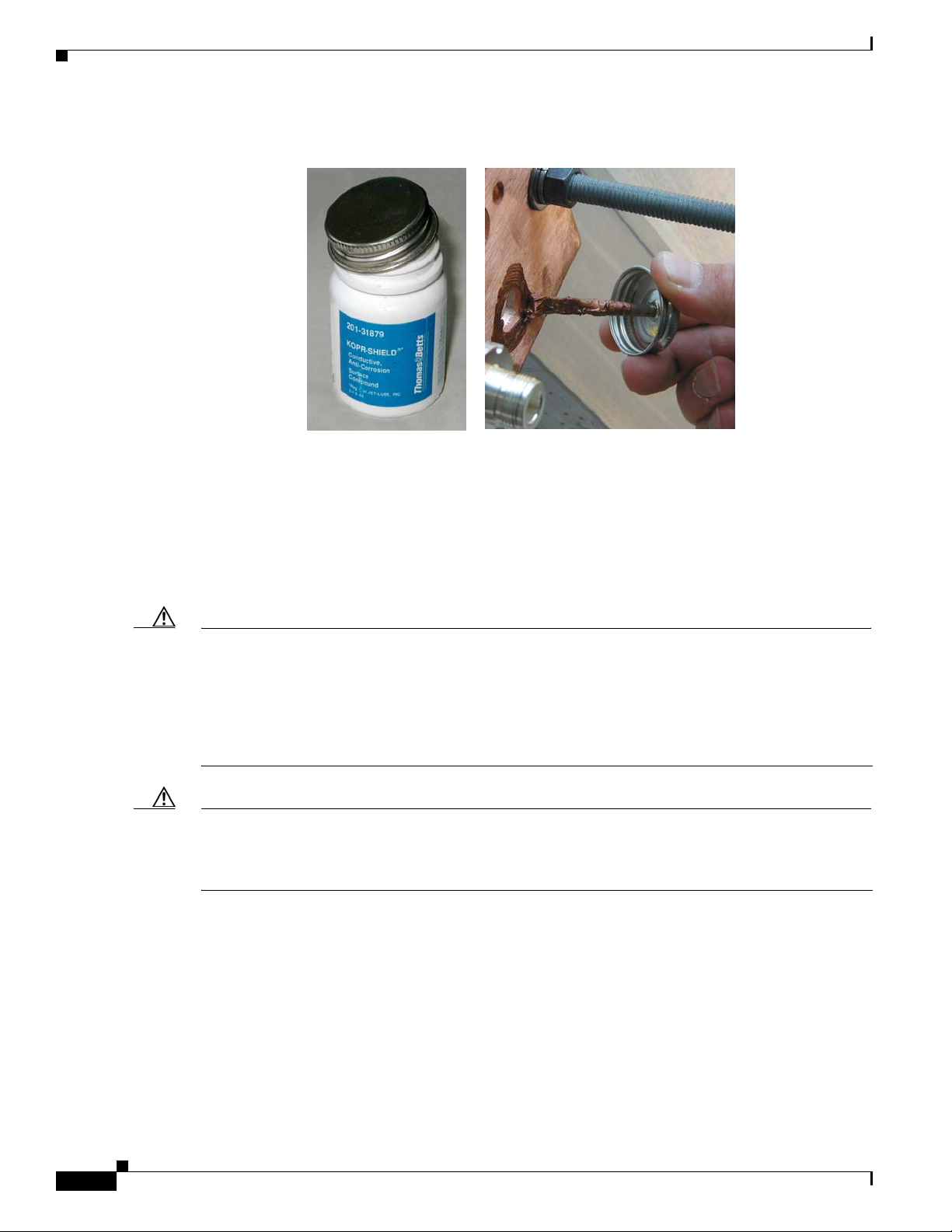
BWX 8305 Basestation Antenna Installation
Figure 6-7 Apply Anti-oxidant Joint Compound
Chapter 6 Installation
6.3.4 Antenna Seperation
When installing multiple BSs in the same geographical area, it is important to allow enough radiation
separation so that they do not interfere with one another.
for avoiding adjacent interference. The illustration shows the horizontal and vertical separation in feet
and in meters for panel antennas.
Caution There can be no co-location of MC-SCDMA with Mobile WiMAX Basestations. If 2 or more BSs are
co-located on the same structure, they must run the same technology or be upgraded in the same
maintenance window. Use frequency separation to minimize interference between a MC-SCDMA and
Mobile WiMAX Basestation. A reasonable frequency separation is 15 MHz for BSs that are 2 kilometers
apart. The exact frequency separation may differ on a case-by-case basis. Therefore, 15 MHz with 2
kilometers between Basestations may not provide enough separation. Refer to the BWX Mobile WiMAX
Migration Planning Guide for more information on distance requirements.
Caution All BSs in a network must have the same DL/UL symbol ratio. The default recommended ratio is 32/15.
Cisco does not support basestations that use different DL/UL symbol ratios in the same area because they
will interfere with each other. Please refer to the BWX EMS Configuration Guide for more information
on parameter settings.
Figure 6-8 provides some general guidelines
6-8
BWX 2305 Basestation Installation and Commissioning Guide
OL-16336-02
Page 45

Chapter 6 Installation
Figure 6-8 General Separation Guidelines
HORIZONTAL SEPARATION (TOP VIEW)
HORIZONTAL SEPARATION (TOP VIEW)
Panel
Panel
Panel
Panel
Panel
Panel
5 ft
5 ft
5 ft
(1.5 m)
(1.5 m)
(1.5 m)
Panel
Panel
Panel
120°
120°
120°
5 ft
5 ft
5 ft
(1.5 m)
(1.5 m)
(1.5 m)
BWX 8305 Basestation Antenna Installation
VERTICAL SEPARAT ION
VERTICAL SEPARAT ION
(SIDE VIEW)
(SIDE VIEW)
Panel
PanelPanel
PanelPanel
PanelPanel
3 ft
3 ft
3 ft
(1 m)
(1 m)
(1 m)
PanelPanel
Panel
PanelPanel
Panel-Panel
Panel-Panel
Panel-Panel
Panel-Panel
6.3.4.1 Vertical Separation - Cisco to Another Vendor
The minimum vertical separation between any Cisco BWX 8305 Basestation antenna and another
vendor’s antenna is 10 ft. Refer to
Figure 6-9 Vertical Separation (Cisco to Other Vendor’s Antenna)
Figure 6-9.
Horizontal
Horizontal
Horizontal
Horizontal
5 ft (1.5 m)
5 ft (1.5 m)
5 ft (1.5 m)
5 ft (1.5 m)
Vertical
Vertical
Vertical
Vertical
3 ft (1 m)
3 ft (1 m)
3 ft (1 m)
3 ft (1 m)
OL-16336-02
BWX 2305 Basestation Installation and Commissioning Guide
6-9
Page 46

BWX 8305 Basestation Antenna Installation
6.3.4.2 Vertical Separation – Cisco to Cisco
A minimum of 3 ft separation in the vertical axis is required between any two Cisco antennas
(
Figure 6-10). This separation is needed to obtain proper and optimum results from each antenna.
Figure 6-10 Vertical Separation (Cisco to Cisco)
Chapter 6 Installation
6.3.4.3 Horizontal Separation – Cisco to Another Vendor
A minimum of 10 ft horizontal separation is required between a Cisco antenna and another vendor’s
antenna (
Figure 6-11 Horizontal Separation (Cisco to Another Vendor’s Antenna)
Figure 6-11).
6-10
BWX 2305 Basestation Installation and Commissioning Guide
OL-16336-02
Page 47

Chapter 6 Installation
6.3.4.4 Horizontal Separation – Cisco to Cisco
A minimum of 3 ft of separation between Cisco Panel antennas is required.
6.3.4.5 No Antenna Zone
If a vertical and horizontal cone extends 15 ft in front of a 120° Panel antenna, this lessens the 10 ft
horizontal and vertical requirements for the placement of the antennas (
lesser requirements, the Service Provider accepts some limitations:
• Signal reflection from the antenna or obstruction
• Shadowing or dead zone in coverage caused by antenna or obstruction
• The amount of reflection and shadowing is affected by the size of the antenna or obstruction
Figure 6-12 No Antenna Zone
BWX 8305 Basestation Antenna Installation
Figure 6-12). By using these
OL-16336-02
BWX 2305 Basestation Installation and Commissioning Guide
6-11
Page 48

BWX 8305 Basestation Antenna Installation
)
)
)
[
]
(
)
(
p
y
6.3.5 Rooftop Antenna Placement Tool
Reference: Rooftop Antenna Placement Tool
This is a picture of the worksheet in the Antenna Placement Tool for a quick visual identification
Figure 6-13); this appendix does not include the entire tool. Please use the electronic copy of the tool to
datafill the site information. This form can be found on the following LiveLink site:
https://tools.cisco.com/cws/livelink?func=ll&objid=4353291&objaction=browse
The Tool is updated periodically. If you are not sure that you have the latest version, please contact Cisco
Technical Services and request that the latest version of the tool be sent to you.
Figure 6-13 Rooftop Antenna Placement Tool
Chapter 6 Installation
2 X hal f the Ver t i c a l Be am wi dt h
ht
Side View
Antenna Azimuth
Upper Roof
Legend
User input required
Calculated Value
Cisc o Antenn a Beam Width s (3 dB poin t)
RFS8 Panel 5° 120°
RFS2 7° 120°
Cis co Antenna Fixed Electrical Downtilt (@ 0 degr ees mechanic al tilt)
RFS8 Panel -6°
RFS2 0°
Vertical Beamwidth
d1
Sector R FS
Horizontal B eamwidth = 120°
(+/- 60°) from the antenna Azimuth
d1 = th e d i st a nce to
Lower Roof
the farthest edge of
Vertical Horizontal
a1
h1
top view
the roof
Ma in B eam
Cen ter P o in t
BWX Rooftop Antenna Placement Tool
1). Are the measurements in feet or meters? Feet
. What type of antenna is being used?
2
. How many sectors are being used? 1
3
4). What is farthest distance (d1) on the roof within the sector antenna's
horizontal beamwidth?
For a single sector antenna on a rooftop the actual antenna pattern will
extend to ~90° to the left / right of the antenna centerline, although at a
reduced signal level relative to the 3dB beam width, If more than 120° of
coverage is desired, then d1 should be the farthest distance to the roof edge
within +/- 90° of the antenna centerline.
3). What is the height of the obstruction or parapet wall (h1 ) ?
. What is the built-in electrical downtilt of the antenna in degrees? -6
4
See electrical downtilt choices for Cisco supplied antennas
Use a negative number for all entries
4). What is the planned mechanical tilt of the antenna in degrees ?
[See RF Planning documents] (+ = uptilt and - = downtilt)
Net Downtilt = Fixed Electrical Downtilt + Mechanical Up/Down Tilt) -6
(Negative for a net downtilt and positive for a net uptilt)
5). What is the 3dB vertical beam width of the antenna?
[Se e Vert ical Beam width cho i ces f or C isco supplied antennas]
6). The Required Clearance Angle ( a1 ) is the sum of the downtilt + two
times half the vertical beam width + 3 extra degrees to allow for any
additional downtilt for future network o
7). This is the minimum required antenna height from the rooftop (ht)
to provide sufficient signal clearance
necessar
timization.
RFS8
55.0
10.0
17.73 ft
0
5
8
BWX 2305 Basestation Installation and Commissioning Guide
6-12
OL-16336-02
Page 49

Chapter 6 Installation
6.3.6 Set the Downtilt
Based on coverage objectives determined by previous RF planning, the BWX 8305 Basestation Antenna
may need adjusting upward or downward once mounted on the pole, tower, roof, building, or other
structure. The panel antenna has a -6° built-in electrical downtilt.
You will use an inclinometer to read the mounted position and to determine what adjustments, if any,
need to be made. For example, if the inclinometer reads +2° (uptilt) and you are mounting a panel BWX
8305 Basestation Antenna, the resulting beam has a –4° downtilt (
adjusted per the assembly shown in Figure 6-15.
Figure 6-14 Downtilt Adjustment Example
BWX 8305 Basestation Antenna Installation
Figure 6-14). The downtilt can be
1
1
1
°
°
°
+
+
+
t
t
t
n
n
n
e
e
e
r
r
r
a
a
a
p
p
p
p
p
p
A
A
A
Electrical –6°
Electrical –6°
Electrical –6°
E
E
E
f
f
f
f
f
f
e
e
e
c
c
c
t
t
t
iv
iv
iv
e
e
e
–
–
–
5
5
5
°
°
°
The inclinometer reads +1° (uptilt)
The panel antena has a
–6° built in
electrical downtilt
The resulting beam has a –5° downtilt
OL-16336-02
BWX 2305 Basestation Installation and Commissioning Guide
6-13
Page 50

BWX 8305 Basestation Antenna Installation
Figure 6-15 Downtilt Adjustment Assembly
Chapter 6 Installation
Downtilt
Adjustment
Cover removed to show PAs
6-14
BWX 2305 Basestation Installation and Commissioning Guide
OL-16336-02
Page 51

Chapter 6 Installation
6.3.7 Antenna Orientation
The magnetic declination, which is the angular difference between observed magnetic north on a
compass and geographic (or “true”) north, shifts from year to year. Panel antennas must be oriented
appropriately as required by the RF plan.
Adjustments that will need to be made are based on the Magnetic Declination Chart (Figure 6-16), which
provides values to correct the compass reading and determine the true geographic East. Always check
for the latest chart information, which may be found at the following web address:
www.thecompassstore.com/decvar.html.
Since this is not the year 2000 any more, you will want to check this reference chart to learn how your
magnetic declination may have shifted since then. Notice that the map measures annual shifts in minutes.
Since it takes 60 minutes to equal 1 degree, if you notice that your location has a declination shift of 5
minutes per year, this means it will be another 12 years before your declination adjustment changes by
one whole degree.
Figure 6-16 Magnetic Declination Chart – Example
BWX 8305 Basestation Antenna Installation
World Magnetic Declinati on Chart - Year 2000
World Magnetic Declinati on Chart - Year 2000
OL-16336-02
Unit:Degrees
Unit:Degrees
Use a compass to determine the magnetic East
Use a Magnetic Declination chart to correct the compass reading
and determine the true geographic East
Note It is better to convert the “true” azimuth (which way the antenna should point in the horizontal plane) as
required by the RF Plan to the magnetic value that will be read on the compass before sending the
installer to the field. This way the installer will go by the reading on the compass, not having to worry
about magnetic declination corrections.
BWX 2305 Basestation Installation and Commissioning Guide
6-15
Page 52

Chapter 6 Installation
BWX 8305 Basestation Antenna Installation
6.3.8 Record Cable Loss and BWX 8305 Basestation Antenna Data in the
Closeout Tool
6.3.8.1 RF Cable Sweeps
At this time, sweep each cable (including Cal cable) according to the following procedure.
Step 1 Connect the Signal Generator directly to the Spectrum Analyzer using a barrel connector.
Signal
Signal
Generator
Generator
Spectrum
Spectrum
Analyzer
Analyzer
Step 2 In the Signal Generator:
a. Set the Center Frequency to the desired value.
Step 3 In the Spectrum Analyzer:
a. Set the Center Frequency to the same value as in the Signal Generator.
b. Set the Span to 5 MHz.
c. Set both the Resolution Bandwidth and the Video Bandwidth to 100 KHz.
d. Verify that the Sweep is set to "Auto".
e. Press the Amplitude button and rotate the wheel until you can see the peak of the signal.
f. Set the Marker to the peak of the signal.
Step 4 In the Signal Generator:
a. Adjust the level of the signal until you read 0.0 dBm in the Spectrum Analyzer screen.
Step 5 Insert the cable to be measured and read the insertion loss in the Spectrum Analyzer window. Compare
the Spectrum Analyzer value to the printed tag that came with the cables. If there is a large discrepancy
between the numbers, check the connectors and re-sweep. Repeat the process at the frequencies above
and below your center frequency (marked “High” and “Low” on the cable sticker). Sweep all cables and
jumpers.
6-16
BWX 2305 Basestation Installation and Commissioning Guide
OL-16336-02
Page 53

Chapter 6 Installation
Step 6 Manually fill in the values in the WiMAX I&C Closeout form under the “Cable Loss” tab. Fill in RF
BWX 8305 Basestation Antenna Installation
Cables #1 and #8, as well as the Cal Cable.
OL-16336-02
Note The figure entered will be the result of adding the bundled cable (antenna to Bus bar) loss with
the jumper cable (Bus bar to BWX 8305 faceplate) loss for each path and the Cal cable.
BWX 2305 Basestation Installation and Commissioning Guide
6-17
Page 54

BWX 8305 Basestation Antenna Installation
6.3.8.2 Enter BWX 8305 Basestation Antenna Data
The CD that accompanies the antenna contains an HTML file (under the RFS folder).
Open the WiMAX I&C closeout Tool (should be open from the Cable Sweeps). Click on the “RFS and
Cable RFS loss” tab. Press the “Insert RFS data” button. When prompted to open a file, find the HTML
file under the RFS folder in the CD, and click “Open”. This will automatically populate the top half of
the tab. See
Figure 6-17 RFS & Cable Loss (Top Half of Worksheet)
Figure 6-17.
Chapter 6 Installation
6.3.9 Connect Bundled Cables to BWX 8305 Basestation Antenna
6.3.9.1 Types of Cable
All BS cable connections are made using standard RF coaxial cable. In Figure 6-18 are examples of
various coaxial cables sold in the United States. Note that the RG-6 or RG-11 bundled cable contains 8
antenna element cables and a Calibration (“Cal”) cable. Reducing several single cables into one bundled
cable makes installation easier and helps eliminate power loss through the cables.
The bundled cable comes with a weatherized boot and 9 N-type connectors in place. At the other end the
connectors can be N-type if the cables are to be connected to surge protectors in the bus bar (Primary
Surge Protection), or QMA-type connectors if the cables are to be connected directly to the BS
(Secondary Protection only). Examples are shown in
jumper cables are needed to connect the surge protectors in the bus bar to the BS.
BWX 2305 Basestation Installation and Commissioning Guide
6-18
Figure 6-19. In the first case, N-type to QMA-type
OL-16336-02
Page 55

Chapter 6 Installation
Figure 6-18 Examples of Coaxial Cables
Figure 6-19 Examples of Connectors
N-type QMA RJ45/RJ48
N-type QMA RJ45/RJ48 BNC
N-type QMA RJ45/RJ48
N-type QMA RJ45/RJ48 BNC
HELIAX
HELIAX
RG6 RG11
RG6 RG11
BWX 8305 Basestation Antenna Installation
RG6 Bundle
M
M
M
M
M
M
M
M
6.3.10 Sweep the BWX 8305 Basestation Antenna
6.3.10.1 Purpose
Once the BWX 8305 Basestation Antenna and bundled RF cables are installed, you must perform a
sweep on the mounted BWX 8305 Basestation Antenna and connected cables. These will be swept for
power loss associated with both the transmit and receive signal. For this measurement you will need a
Cisco proprietary tool called the BWX Basestation Antenna Test Box. The sweep procedure is different
for the transmit and receive paths. In all cases you first establish a reference level, then measure the path
gain or loss test.
6.3.10.2 Equipment Required
• Spectrum Analyzer (SA)
• Signal Generator (SG)
• Cisco BWX Basestation Antenna Test Box (formerly referred to as the RFS Test Box)
• RF cables and connectors
6.3.10.3 Equipment Setup to Establish a Transmit (TX) Path Reference Level
Follow the setup instructions provided in Figure 6-20 to first determine a reference level.
BWX 2305 Basestation Installation and Commissioning Guide
OL-16336-02
6-19
Page 56
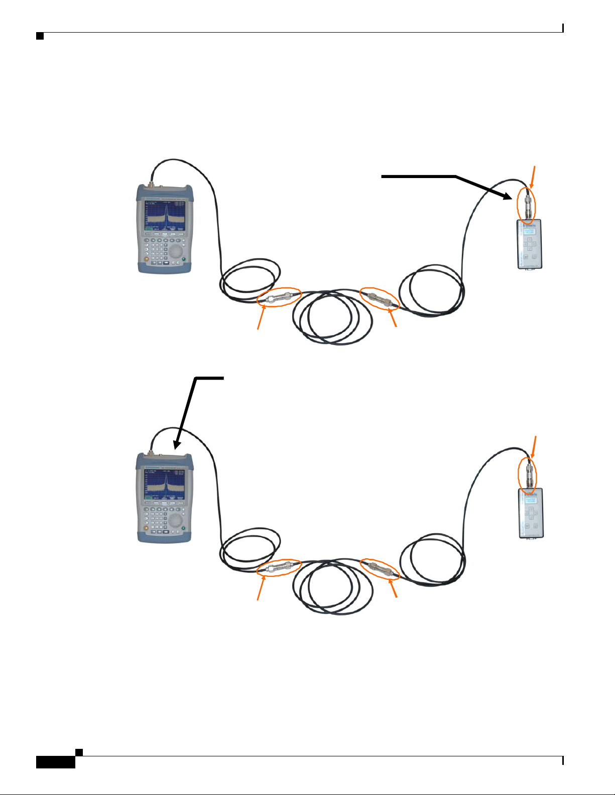
BWX 8305 Basestation Antenna Installation
Figure 6-20 Setup to Establish a TX Path Reference Level
Interconnect the Signal Generator
SG and the Spectrum Analyzer SA
using three segments of N-Type
cable and two barrel connectors
In the Signal Generator:
Insert a 20 dB attenuator
Set the Center Freq uency to the
desired value
Chapter 6 Installation
20 dB
attenuator
SA
SA
The RFS will
be inserted here
In the S pectrum A nalyze r :
Set the Center Frequency to the same value
as in the Signal Generator
Set the Span to 5 MHz
Set both the Resolution Ban dwidth and the
Video Ban dwidt h to 100 kHz
Verify that the Sweep is set to "Auto"
Press th e Amplitude button and rotate the
wheel until you can see the peak of the signal
Set the Marker to the peak of the signal
The read i ng in the Spect r um Analy ze r
(approx –20 dBm) is your Reference Level
SG
The Test Box
will be inserted here
20 dB
attenuator
SG
6-20
The RFS will
be inser ted he re
BWX 2305 Basestation Installation and Commissioning Guide
The Test Box
will be inserted here
OL-16336-02
Page 57

Chapter 6 Installation
6.3.10.4 Procedure to Establish a TX Path Reference Level
For this procedure, you must first establish a reference level. Follow these steps to do so.
Step 1 Set up the equipment, as shown in Figure 6-20, for Signal Generator amplitude and frequency, and for
Spectrum Analyzer span, bandwidth resolution, video bandwidth, sweep, and frequency.
Step 2 Connect the Signal Generator to the Spectrum Analyzer using 3 segments of N-type terminated test cable
and 2 F-F barrel connectors.
Step 3 Turn on the RF signal.
Step 4 Adjust the Signal Generator signal until the value in the Spectrum Analyzer is approximately –20dbm.
Step 5 Make sure the Test Box is not connected to power.
6.3.10.5 Equipment Setup to Measure TX Path Gain or Loss
Follow the setup instructions provided in Figure 6-21 to measure the BWX 8305 Basestation Antenna
transmit path gain or loss.
BWX 8305 Basestation Antenna Installation
Figure 6-21 Setup to Measure TX Path Gain or Loss
Set Test Box to
TX
RFS
The loss
introd uced by
the Test Box
at dif ferent
frequencies
can be read
on this label
on the side
RF
Insert the Test Box and the RFS
Connect the SG to JP-2 (test box side),
SG
JP-1 (test box top) to one of the RF ports
in the RFS, and the RFS Cal Port to the SA
Switch the Test Box to TX and RFS
Power Up the test box (+24 VDC)
Measure gain introduced by this path through
the RFS (repeat for each RF port)
RFS Insertion Gain = SA Reading
+20 dB (i.e. –Referen c e Level)
+ Test Box loss
SA
CAL
OL-16336-02
Warning
Any time you reconnect the cable, going form the JP-1 QMA connector, located on the topof the RFD
Test Box, to one of the RF ports in the ANtenna, make sure to disconnect the RFS Test Box from its
power source. Failing to this may cause rapid degradation of the QMA connector in the RFS Test Box,
due to DC voltage arc between the center conductor and the outer shield of the QMA connector.
BWX 2305 Basestation Installation and Commissioning Guide
6-21
Page 58

BWX 8305 Basestation Antenna Installation
Caution Never connect the Cisco BWX Basestation Antenna Test Box to the Calibration (Cal) port on the BS or
to other test equipment. The output voltage may destroy the equipment.
Note Be sure to power down the Test Box each time you change cables to sweep. Failure to do so may damage
the Test Box.
6.3.10.6 Procedure to Measure TX Path Gain or Loss
Note Do not attempt to sweep the BWX 8305 Basestation Antenna while it is on cement or metal, as this can
cause reflections that misconstrue the data.
Step 1 Using Figure 6-21 above as a guide, insert the BWX 8305 Basestation Antenna and the Test Box.
Step 2 Connect the Signal Generator to the JP-2 on the Test Box side, and JP-1 to one of the RF ports on the
BWX 8305 Basestation Antenna. Connect the BWX 8305 Basestation Antenna Cal port to the Spectrum
Analyzer.
Step 3 Power up the Test Box.
Chapter 6 Installation
Step 4 Measure the gain or loss introduced by this path through the BWX 8305 Basestation Antenna. Repeat
the procedure for each path. Check the SA value to the printed values that accompanied the Antenna. If
there is a large discrepancy, check the connections and repeat the sweep.
Step 5 Subtract the loss at the Test Box.
Step 6 Repeat Steps 4 and 5, connecting the cable from JP-1 to the other RF port.
Step 7 Turn off the RF signal. Change the frequency and repeat this process for the High and Low frequencies
(matching the printed sheet that came with the antenna).
Step 8 Power down and remove the Test Box.
6.3.10.7 Procedure to Establish the Receive (RX) Path Reference Level
Step 1 Set up the equipment, as shown in Figure 6-20, for Signal Generator amplitude and frequency, and for
Spectrum Analyzer span, bandwidth resolution, video bandwidth, sweep, and frequency.
Step 2 Connect the Signal Generator to the Spectrum Analyzer using 3 segments of N-type terminated test cable
and 2 F-F barrel connectors.
Step 3 Turn on the RF signal.
Step 4 Adjust the Signal Generator signal until the value in the Spectrum Analyzer is approximately –20dbm.
Step 5 Make sure the Test Box is not connected to power.
6-22
BWX 2305 Basestation Installation and Commissioning Guide
OL-16336-02
Page 59

Chapter 6 Installation
6.3.10.8 Equipment Setup to Measure the RX Path Gain or Loss
To establish a reference level for the receive path gain or loss, you will connect the Signal Generator to
the Spectrum Analyzer using 3 segments of N-type terminated test cable and 2 F-F barrel connectors
(
Figure 6-22). Later, you will have to subtract the loss introduced by the Test Box. Set the signal
amplitude to –20 dBm.
Figure 6-22 Setup to Establish RX Path Reference Level
Set Test Box to
Set Test Box to
RX
RX
RFS
RFS
SA
The loss
introd uced by
the Test B ox
at different
frequencies
can be read
on this label
on t he side
Insert the Test Box and the RFS
Measure gain introduce d by this p a th through
RF
Connect the SG to the Cal Portof the RFS,
one of the RF ports in the RFS to JP-1 (test box top), JP-2
(test box side) to the SA
Switch the Test Box to RXand RFS
Power Up the tes t box (+2 4 VDC)
the RFS (repeat for each RF port)
RFS Insertion Gain = SA Reading
BWX 8305 Basestation Antenna Installation
CAL
SG
+20 dB (i.e. – R ef erence Leve l)
+ Test Box lo ss
6.3.10.9 Procedure to Measure the RX Path Gain or Loss
Note Be sure to power down the Test Box each time you change cables to sweep. Failure to do so may
damage the Test Box.
Step 1 Insert the BWX 8305 Basestation Antenna (RFS) and the Test Box.
Step 2 Using Figure 6-22 as a guide, connect the Signal Generator to the BWX 8305 Basestation Antenna Cal
port, and one of the RF ports on the BWX 8305 Basestation Antenna to JP-1 on the top of the Test Box.
Connect JP-2 on the side of the Test Box to the Spectrum Analyzer.
Step 3 Power up the Test Box.
Step 4 Measure the gain or loss introduced by this path through the BWX 8305 Basestation Antenna. Repeat
the procedure for the other path. Check the SA value to the printed values that accompanied the Antenna.
If there is a large discrepancy, check the connections and repeat the sweep.
Step 5 Subtract the loss at the Test Box.
Step 6 Repeat Steps 4 and 5, connecting the cable from JP-1 to the other RF port.
BWX 2305 Basestation Installation and Commissioning Guide
OL-16336-02
6-23
Page 60

BWX 8305 Basestation Antenna Installation
Step 7 Turn off the RF signal. Change the frequency and repeat this process for the High and Low frequencies
(matching the printed sheet that came with the antenna).
Step 8 Power down and remove the Test Box.
6.3.10.10 Record BWX 8305 Basestation Antenna Data in Closeout Tool
After you have swept the BWX 8305 Basestation Antenna TX and RX paths, record the results in the
“RFS and Cable Sweeps Information” worksheet in the Closeout Tool form (
Figure 6-23 RFS TX & RX Path Gain/Loss
Chapter 6 Installation
Figure 6-23).
6-24
BWX 2305 Basestation Installation and Commissioning Guide
OL-16336-02
Page 61

Chapter 6 Installation
6.4 BWX 8305 Basestation Installation
6.4.1 Overview
The BS is a lightweight unit that fits easily into standard Telecom racks. All connectors and indicators
on the BS are on the faceplate (
two cards inside the BS are not field replaceable. Therefore, if a severe Fault occurs, the entire unit is
removed and replaced. The design intent is to cut down on the time it takes to troubleshoot or otherwise
have a field support person onsite.
Figure 6-24 BWX 8305 Basestation Faceplate
Console
Console
Port
Port
Figure 6-24). Inside the unit are two cards: Digital and RF. Note that the
2 Ethernet Ports
2 Ethernet Ports
MGMT
Data
Data
MGMT
(not used at
(not used at
this time)
this time)
BWX 8305 Basestation Installation
5 LEDs
5 LEDs
Fault
BootingPower GPSRF
BootingPower GPSRF
Fault
RF Ports
RF Ports
8–5
8–5
+24 VDC/ 4 0A
+24 VDC/ 4 0A
Power Input
Power Input
(Also available:
(Also available:
-48 VDC/30A and
-48 VDC/30A and
100-240VAC/50-60 Hz/1 0A)
100-240VAC/50-60 Hz/1 0A)
On/Off
On/Off
Switch
Switch
CAL
CAL
Port
Port
10 MHz
10 MHz
10 MHz
1 PPS
1 PPS
1 PPS
External Precise
External Precise
External Precise
Clocking Source
Clocking Source
Clocking Source
Grounding
Grounding
Lug
Lug
RF Por ts 4–1
RF Por ts 4–1
The Console Port, Ethernet Port, 8 RF Ports, Cal Port, GPS Port, Power, and Grounding connectors are
located on the faceplate. There are also five LED indicators at the top middle of the faceplate.
• The Power indicator is lit when the power is on.
• The Booting indicator flashes when the system is booting up, and it turns off when booting is
complete. The middle light, the Fault indicator, will flash red if there is a hardware fault, such as
operating temperature out of range or an antenna path is not functioning.
• The RF indicator indicates that one or more RF antenna paths are turned on and radiating energy.
OL-16336-02
• Lastly, the GPS Lock indicator on the far right is lit to indicate that the BS is locked to its timing
source - the BWX 8303 Basestation Timing System.
At no time should a field person remove the back of the unit or otherwise open it. In fact, doing so
may void the warranty.
Cisco recommends 5% spares planning for BS.
BWX 2305 Basestation Installation and Commissioning Guide
6-25
Page 62

BWX 8305 Basestation Installation
6.4.2 Housing
Chapter 6 Installation
Reference: Appendix F, “BWX 8305 Basestation Outdoor Enclosure Manufacturers”
The BS can be installed either indoor in a standard 19” or 23” equipment rack, or outside in a climatized
cabinet (
If you are placing the BS in an outdoor cabinet, be sure to consider solar gain and other environmental
factors when determining cooling requirements, filtering, etc.
In either environment, the BS must be installed in a restricted access location, in accordance with
NEC/CEC standards. Only authorized personnel should have access to this equipment.
Figure 6-25 Outdoor Cabinet Example
Figure 6-25). If you are using a 23” indoor rack, you will need mounting adapters.
BWX 8305 + Antenna (in Watts)
BWX 8305 + Antenna (in Watts)
BWX 8305 + Antenna (in Watts)
BWX 8305 + Antenna (in Watts)
2.3 700
2.3 700
2.3 700
2.3 700
2.4 430
2.4 430
2.4 430
2.4 430
2.5 700
2.5 700
2.5 700
2.5 700
2.6 700
2.6 700
2.6 700
2.6 700
3.4 772 (w/H-Antenna)
3.4 772 (w/H-Antenna)
3.4 772 (w/H-Antenna)
3.4 772 (w/H-Antenna)
3.5 772 (w/H-Antenna)
3.5 772 (w/H-Antenna)
3.5 772 (w/H-Antenna)
3.5 772 (w/H-Antenna)
3.6 772
3.6 772
3.6 772
3.6 772
6.4.3 Power & Grounding
Reference: Appendix A, “Rectifier/Battery Backup Suppliers”
6.4.3.1 Overview
The BS can be ordered with one of the following power inputs:
1. + 24 VDC
2. - 48 VDC
3. 100-240, 47/63 Hz VAC
General power and grounding information were covered in Chapter 5, “Pre-installation.” Please refer
there for information about Primary and Secondary surge protection for the BS.
BWX 8305 (in Watts)
BWX 8305 (in Watts)
BWX 8305 (in Watts)
BWX 8305 (in Watts)
2.3 350
2.3 350
2.3 350
2.3 350
2.4 315
2.4 315
2.4 315
2.4 315
2.5 350
2.5 350
2.5 350
2.5 350
2.6 350
2.6 350
2.6 350
2.6 350
3.4 - 3.5 370 (w/H-Antenna)
3.4 - 3.5 370 (w/H-Antenna)
3.4 - 3.5 370 (w/H-Antenna)
3.4 - 3.5 370 (w/H-Antenna)
3.6 350
3.6 350
3.6 350
3.6 350
Thermal load equates to how much cooling is needed
Thermal load equates to how much cooling is needed
Thermal load equates to how much cooling is needed
to cool the Basestation. Multiply this by 3.5 and you
to cool the Basestation. Multiply this by 3.5 and you
to cool the Basestation. Multiply this by 3.5 and you
will have the B TU rating.
will have the B TU rating.
will have the B TU rating.
6-26
BWX 2305 Basestation Installation and Commissioning Guide
OL-16336-02
Page 63

Chapter 6 Installation
6.4.3.2 External Power Source / Supply Considerations
Note the following considerations for the - 48V and + 24V BS chassis:
a. An external method of disconnecting each of the DC power Load/Return lines to the BS chassis
is required, either through fuse + disconnect device(s) or a dual-pole breaker. The fuse/breaker
rating must be minimum 10% higher than that of the BS Chassis breaker but shall not exceed
70A.
b. The external DC power source, if current limited, shall have the limit set-point configured
higher than the BS Chassis breaker rating.
c. The external supply "Return" and the BS chassis shall be bonded to a common Earth ground.
The BS Chassis has an external ground lug provided.
d. Do not remove protective earth connection before disconnecting the Basestation from the DC
power supply.
6.4.3.3 BWX 8305 Ground Bus Bar Installation Procedure
Prior to connecting power and grounding to the equipment, be sure to check all regulatory requirements.
Follow accepted Telecom standards and procedures to connect input power and grounding to the BS. The
gauge of the wire is determined by the length of the run and by NEC/CEC standards (refer to Regulatory
information in the front of this document). Use a 60-amp circuit breaker when running the line.
Terminate both of the input power wires and the ground wire with a ¼-inch terminal lug.
BWX 8305 Basestation Installation
Warning
Warning
Ensure that the power is off before connecting the input power wires to the BS input terminals.
The power supply range must meet specifications for BS components.
Install the rubber gasket into the groove in the surge protector:
a. Install the surge protector in the system ground bus bar with the surge side toward the antenna
and the protected side toward the BS.
b. Install the star washer and nut on the top of the surge protector. Torque the nut to 140-150
inch-pounds.
6.4.3.4 Install Jumper Cables
Next, install the jumper cables from the lower bus bar to the Basestation.
6.4.3.5 System Ground Wiring
Install the system ground as a single point connection between the system ground bus bars, the BS unit,
the BS mounting rack, and the BWX 8305 Basestation Antenna. Connect the system ground to earth
ground. AWG #6 is used between the equipment and the bus bar, and AWG #2 is used from the bus bar
to the earth ground. Always refer to the regulatory standards for power and grounding. Apply
anti-oxidant joint compound to all connections (
Figure 6-26). Tighten all connections until secure.
OL-16336-02
BWX 2305 Basestation Installation and Commissioning Guide
6-27
Page 64

BWX 8305 Basestation Installation
Figure 6-26 Apply Anti-oxidant Joint Compound
To protect against corrosion, the Installer should apply an anti-corrosive compound to each connection
point (
due to climate effects. For the power and grounding cables, also look at Figure 6-28 concerning the use
of heat shrink tubes.
Figure 6-27 Terminating Power Cables
Chapter 6 Installation
Figure 6-27). This is especially necessary for the BWX 8305 Basestation Antenna connections
Apply Anti -corrosive UL Listed Lugs Insert LugsKopr Shield
Apply Anti -corrosive UL Listed Lugs Insert LugsKopr Shield
Crimp Cover with el ectrical tape
Crimp Cover with el ectrical tape
Figure 6-28 Terminating Grounding Cables
or heat-shrink t ub e
or heat-shrink t ub e
Apply Anti-
Apply Anti-
corrosive
corrosive
Attach
Attach
6-28
BWX 2305 Basestation Installation and Commissioning Guide
OL-16336-02
Page 65

Chapter 6 Installation
6.4.4 Install Basestation Unit
Connect BWX 8303 Basestation Timing System
Warning
Caution The RF ports on the BS output a +24 VDC current, which is carried to the BWX 8305 Basestation
Ensure that the power to the BS unit is OFF before installing the unit in a rack or cabinet.
Place the BS unit into a standard 19” or 23” rack or outdoor enclosure. Once installed, go ahead to the
next section of this Guide and install the BWX 8303 Basestation Timing System. After the BWX 8303
Basestation Timing System is installed and its cables swept, you will return to the remaining BS
installation. Please note that the BS does not have an air filter option like its predecessor BS.
Antenna through RF cables. This DC current may damage test equipment connected directly to the RF
ports or to the end of the RF cables at the BWX 8305 Basestation Antenna. When connecting test
equipment to the output of an RF port, an external DC block may be required. Most signal generators
and spectrum analyzers cannot handle DC voltage on the I/O ports. Please, read the caution stickers on
the equipment and provide a DC block if the equipment cannot handle over zero (0) VDC.
6.5 Connect BWX 8303 Basestation Timing System
Reference: BWX 8303 Basestation Timing System Operation & Maintenance Manual
Note The BWX 8303 Basestation Timing System is required for WiMAX Basestations.
6.5.1 Overview
Note The BWX 8303 Basestation Timing System unit described here handles the more precise frequency
The BWX 8303 Basestation Timing System is a new feature with BWX 8305 Basestations supporting
WiMAX certification requirements for high-resolution timing. The ports on the BWX 8303 Basestation
Timing System provide 1 pulse per second (1 PPS) and 10 MHz source.
For the BS to be WiMAX certified, the BWX 8303 Basestation Timing System provides very precise
frequency timing to the BS. The BWX 8303 Basestation Timing System receives the timing signal from
the GPS antenna and outputs a 1 pulse per second (PPS) signal, along with an extremely accurate (< 0.02
ppm) 10 MHz reference signal that is locked to the GPS timing. This timing reference is then utilized by
the BS to derive the carrier frequency (2500 MHz, for example) and synchronize its TDD framing to
other Basestations. This Synchronized signaling is important for avoiding interference from co-located
or adjacent BSs. Also, when using the Cisco BWX WiMAX Diagnostics tool, having GPS timing also
permits the system to determine a user’s location via triangulation.
One BWX 8303 Basestation Timing System can provide the required reference signals for up to three
BSs; thus, a single BWX 8303 Basestation Timing System is required for a tri-sectored site.
referencing required for WiMAX mobility, and has its own GPS antenna port. Therefore, the GPS port
from the BS faceplate is not needed for a GPS antenna.
OL-16336-02
BWX 2305 Basestation Installation and Commissioning Guide
6-29
Page 66

Connect BWX 8303 Basestation Timing System
The BWX 8303 Basestation Timing System chassis is 1.75” H x 17” W (19” with rack ears) x 12” D.
The chassis weighs less than 10 pounds. The unit is available with standard 100 to 240 VAC power input
and optional + 24 or - 48 VDC input. BWX 8303 Basestation Timing System status is reported via front
panel LEDs for Power, Lock, and Fault indicators. Standard Ethernet RJ-45 and RS-232 ports are also
available for monitoring and control using http or telnet protocols. SNMP is included in the BWX 8303
Basestation Timing System.
Figure 6-29 BWX 8303 Basestation Timing System Unit
Chapter 6 Installation
Figure 6-29 through Figure 6-31 show the installation capabilities.
1
1
1
1
2
2
2
2
3
3
3
3
4
4
4
4
5
5
5
5
6
6
6
10 MHz
10 MHz
10 MHz
10 MHz
6
DC Power
DC Power
1 PPS
1 PPS
1 PPS
1 PPS
Figure 6-30 BWX 8303 Basestation Timing System connected to BWX 8305
GPS antenna to BS is not need ed
GPS antenna to BS is not need ed
GPS antenna to BS is not need ed
GPS antenna to BS is not need ed
GPS antenna to BS is not need ed
GPS antenna to BS is not need ed
GPS antenna to BS is not need ed
GPS antenna to BS is not need ed
GPS antenna to BS is not need ed
GPS antenna to BS is not need ed
GPS antenna to BS is not need ed
GPS antenna to BS is not need ed
GPS antenna to BS is not need ed
GPS antenna to BS is not need ed
GPS antenna to BS is not need ed
GPS antenna to BS is not need ed
GPS antenna to BS is not need ed
GPS antenna to BS is not need ed
GPS antenna to BS is not need ed
GPS antenna to BS is not need ed
GPS antenna to BS is not need ed
GPS antenna to BS is not need ed
GPS antenna to BS is not need ed
GPS antenna to BS is not need ed
GPS antenna to BS is not need ed
GPS antenna to BS is not need ed
GPS antenna to BS is not need ed
GPS antenna to BS is not need ed
GPS antenna to BS is not need ed
GPS antenna to BS is not need ed
GPS antenna to BS is not need ed
GPS antenna to BS is not need ed
GPS antenna to BS is not need ed
GPS antenna to BS is not need ed
GPS antenna feeds directly into BWX 8303
GPS antenna feeds directly into BWX 8303
GPS antenna feeds directly into BWX 8303
GPS antenna feeds directly into BWX 8303
GPS antenna feeds directly into BWX 8303
GPS antenna feeds directly into BWX 8303
GPS antenna feeds directly into BWX 8303
GPS antenna feeds directly into BWX 8303
GPS antenna feeds directly into BWX 8303
GPS antenna feeds directly into BWX 8303
GPS antenna feeds directly into BWX 8303
GPS antenna feeds directly into BWX 8303
GPS antenna feeds directly into BWX 8303
GPS antenna feeds directly into BWX 8303
GPS antenna feeds directly into BWX 8303
GPS antenna feeds directly into BWX 8303
GPS antenna feeds directly into BWX 8303
GPS antenna feeds directly into BWX 8303
GPS antenna feeds directly into BWX 8303
GPS antenna feeds directly into BWX 8303
GPS antenna feeds directly into BWX 8303
GPS antenna feeds directly into BWX 8303
GPS antenna feeds directly into BWX 8303
GPS antenna feeds directly into BWX 8303
GPS antenna feeds directly into BWX 8303
GPS antenna feeds directly into BWX 8303
GPS antenna feeds directly into BWX 8303
GPS antenna feeds directly into BWX 8303
GPS antenna feeds directly into BWX 8303
GPS antenna feeds directly into BWX 8303
GPS antenna feeds directly into BWX 8303
GPS antenna feeds directly into BWX 8303
GPS antenna feeds directly into BWX 8303
GPS antenna feeds directly into BWX 8303
BWX 8303 outputs 1PPS & 10 MHz signals
BWX 8303 outputs 1PPS & 10 MHz signals
BWX 8303 outputs 1PPS & 10 MHz signals
BWX 8303 outputs 1PPS & 10 MHz signals
BWX 8303 outputs 1PPS & 10 MHz signals
BWX 8303 outputs 1PPS & 10 MHz signals
BWX 8303 outputs 1PPS & 10 MHz signals
BWX 8303 outputs 1PPS & 10 MHz signals
BWX 8303 outputs 1PPS & 10 MHz signals
BWX 8303 outputs 1PPS & 10 MHz signals
BWX 8303 outputs 1PPS & 10 MHz signals
BWX 8303 outputs 1PPS & 10 MHz signals
BWX 8303 outputs 1PPS & 10 MHz signals
BWX 8303 outputs 1PPS & 10 MHz signals
BWX 8303 outputs 1PPS & 10 MHz signals
BWX 8303 outputs 1PPS & 10 MHz signals
BWX 8303 outputs 1PPS & 10 MHz signals
BWX 8303 outputs 1PPS & 10 MHz signals
BWX 8303 outputs 1PPS & 10 MHz signals
BWX 8303 outputs 1PPS & 10 MHz signals
BWX 8303 outputs 1PPS & 10 MHz signals
BWX 8303 outputs 1PPS & 10 MHz signals
BWX 8303 outputs 1PPS & 10 MHz signals
BWX 8303 outputs 1PPS & 10 MHz signals
BWX 8303 outputs 1PPS & 10 MHz signals
BWX 8303 outputs 1PPS & 10 MHz signals
BWX 8303 outputs 1PPS & 10 MHz signals
BWX 8303 outputs 1PPS & 10 MHz signals
BWX 8303 outputs 1PPS & 10 MHz signals
BWX 8303 outputs 1PPS & 10 MHz signals
BWX 8303 outputs 1PPS & 10 MHz signals
BWX 8303 outputs 1PPS & 10 MHz signals
BWX 8303 outputs 1PPS & 10 MHz signals
X
X
X
X
X
X
X
X
X
X
X
X
X
X
X
X
X
X
X
X
X
X
X
X
X
X
X
X
X
X
X
X
X
X
X
X
X
X
X
X
X
X
X
X
X
X
X
X
X
X
X
X
X
X
X
X
X
X
X
X
X
X
X
X
X
X
X
X
X
X
XX
X
XX
X
XX
X
XX
X
XX
X
XX
X
XX
X
XX
X
XX
X
XX
X
XX
X
XX
X
XX
X
XX
X
XX
X
XX
X
XX
X
XX
X
XX
X
XX
X
XX
X
XX
X
XX
X
XX
X
XX
X
XX
X
XX
X
XX
X
XX
X
XX
X
XX
X
XX
X
XX
X
X
GPS Antenna
GPS Antenna
GPS Antenna
GPS Antenna
GPS Antenna
GPS Antenna
GPS Antenna
GPS Antenna
GPS Antenna
GPS Antenna
GPS Antenna
GPS Antenna
GPS Antenna
GPS Antenna
GPS Antenna
GPS Antenna
GPS Antenna
GPS Antenna
GPS Antenna
GPS Antenna
GPS Antenna
GPS Antenna
GPS Antenna
GPS Antenna
GPS Antenna
GPS Antenna
GPS Antenna
GPS Antenna
GPS Antenna
GPS Antenna
GPS Antenna
GPS Antenna
GPS Antenna
GPS Antenna
BWX 8305 Basestation
BWX 8305 Basestation
Basestation
Basestation
Basestation
Basestation
Basestation
Basestation
Basestation
Basestation
BWX 8303 Basestation
BWX 8303 Basestation
BWX 8303 Basestation
BWX 8303 Basestation
BWX 8303 Basestation
BWX 8303 Basestation
BWX 8303 Basestation
BWX 8303 Basestation
BWX 8303 Basestation
BWX 8303 Basestation
BWX 8303 Basestation
BWX 8303 Basestation
BWX 8303 Basestation
BWX 8303 Basestation
BWX 8303 Basestation
BWX 8303 Basestation
BWX 8303 Basestation
BWX 8303 Basestation
BWX 8303 Basestation
BWX 8303 Basestation
BWX 8303 Basestation
BWX 8303 Basestation
BWX 8303 Basestation
BWX 8303 Basestation
BWX 8303 Basestation
BWX 8303 Basestation
BWX 8303 Basestation
BWX 8303 Basestation
BWX 8303 Basestation
BWX 8303 Basestation
BWX 8303 Basestation
BWX 8303 Basestation
BWX 8303 Basestation
BWX 8303 Basestation
Timing System
Timing System
Timing System
Timing System
Timing System
Timing System
Timing System
Timing System
Timing System
Timing System
Timing System
Timing System
Timing System
Timing System
Timing System
Timing System
Timing System
Timing System
Timing System
Timing System
Timing System
Timing System
Timing System
Timing System
Timing System
Timing System
Timing System
Timing System
Timing System
Timing System
Timing System
Timing System
Timing System
Timing System
BWX 8303 outputs 1PPS & 10 MHz signals
to the BS
to the BS
to the BS
to the BS
to the BS
to the BS
to the BS
to the BS
to the BS
to the BS
to the BS
to the BS
to the BS
to the BS
to the BS
to the BS
to the BS
to the BS
to the BS
to the BS
to the BS
to the BS
to the BS
to the BS
to the BS
to the BS
to the BS
to the BS
to the BS
to the BS
to the BS
to the BS
to the BS
to the BS
XX
XXXX
XX
XXXX
6-30
BWX 2305 Basestation Installation and Commissioning Guide
OL-16336-02
Page 67

Chapter 6 Installation
Connect BWX 8303 Basestation Timing System
Figure 6-31 BWX 8303 Basestation Timing System Connected to Tri-sector of BWX 8305
OL-16336-02
The EMS configurable field for External GPS should now be set to “Yes” (Figure 6-32). When upgrading
from MC-SCDMA to BWX Mobile WiMAX, Service Providers will need to add the BWX 8303
Basestation Timing System per the instructions in this BWX 8305 Basestation I&C Guide.
Figure 6-32 External GPS Field Enabled
Set to YesSet to Yes
BWX 2305 Basestation Installation and Commissioning Guide
6-31
Page 68
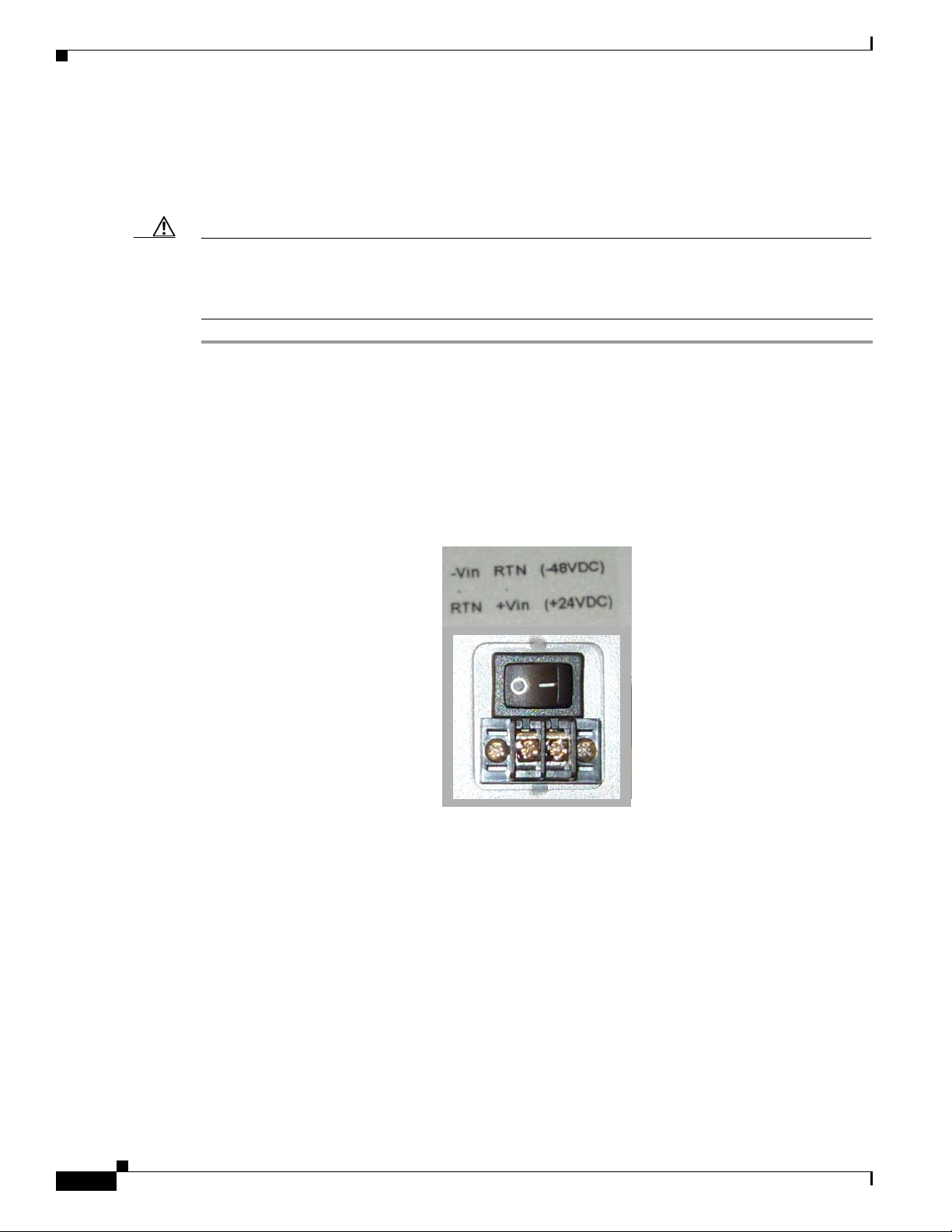
Connect BWX 8303 Basestation Timing System
6.5.2 Install the BWX 8303 Basestation Timing System
Please read the BWX 8303 Basestation Timing System Operation & Maintenance Manual for detailed
information about the BWX 8303 Basestation Timing System unit.
Caution The BXW 8303 Basestation Timing System unit should be powered on and locked (satellite acquisition
completed) PRIOR TO powering on the Basestation(s) connected to it. This initial configuration should
take place in advance of powering up the BWX 8305 Basestation. The initial POS FIX MODE survey
takes approximately 30 - 40 minutes.
Step 1 Install the BWX 8303 Basestation Timing System chassis in the rack.
Step 2 Install the BWX 8303 Basestation Timing System antenna and lightning arrestors, and ground both the
antenna and the chassis (grounding lug is next to power connection on faceplate) per the grounding rules
mentioned earlier in this Guide. There is no need to terminate the BWX 8305 Basestation GPS antenna
port.
Step 3 For DC powered units, connect the power cable to the power connection (on the front faceplate). Refer
to
Figure 6-33 for the correct cable connections for - 48 VDC and + 24 VDC powered units.
Chapter 6 Installation
Figure 6-33 DC Power Connections
Step 4 Connect the BWX 8303 Basestation Timing System to the BS chassis by connecting the 1 PPS and 10
MHz ports on the BS unit to the correct ports on the BWX 8303 Basestation Timing System unit using
the BNC connectors provided (See
Figure 6-30 & Figure 6-31 above). The BWX 8303 Basestation
Timing System ports are numbered 1-3 for the 1PPS output (for connecting up to 3 BSs at a time) and
4-6 for the 10 MHz output connections. A sticker is affixed to the BWX 8303 Basestation Timing System
unit with the port number assignments.
Step 5 Connect the Ethernet cable from the Service Provider’s network into the Ethernet port on the front of the
BWX 8303 Basestation Timing System.
6-32
Step 6 Connect a 9-pin Serial Cable to the RS-232 port on the front of the BWX 8303 Basestation Timing
System for communication and viewing “status” command. Refer to the BWX 8303 Basestation Timing
System Operation & Maintenance Manual for console commands.
BWX 2305 Basestation Installation and Commissioning Guide
OL-16336-02
Page 69

Chapter 6 Installation
Step 7 From the PC, go to Start > Programs > Accessories > TeraTerm > TerTerm, or using whichever
Connect BWX 8303 Basestation Timing System
Note The BWX 8303 Basestation Timing System unit will assign its own IP address, or a console
command can be used to turn on DHCP, and the Service Provider’s network can assign an IP
address. Refer to the BWX 8303 Basestaion Timing System Operation & Maintenance Manual
for console commands.
Note The BWX 8303 Basestation Timing System unit will not send alarms to the EMS. Change the
SNMP to send error messages from the BWX 8303 Basestation Timing System unit to a NMS
server (or other IP Address as required).
terminal emulation program you are running.
Note A VT 100 terminal or any standard Windows-based ASCII terminal emulation program can be
used for connecting to the Console port. The connection for TeraTerm is explained here as an
illustrative example. The steps to get to the TeraTerm program may be different due to variances
between Operating Systems and in the PC setup. The TeraTerm program can be downloaded free
from the Internet.
Step 8 In the COM1 Properties window (reference Figure 6-34), under the Port settings tab enter the
configuration options. Click “OK”.
Figure 6-34 COM1 Properties
Bits per second :
Bits per second :
Bits per second :
Bits per second :
Data Bits:
Data Bits:
Data Bits:
Data Bits:
Pari ty : None
Pari ty : None
Pari ty : None
Pari ty : None
Stop Bits: 1
Stop Bits: 1
Stop Bits: 1
Stop Bits: 1
Flow Control: None
Flow Control: None
Flow Control: None
Flow Control: None
Step 9 Power on the BWX 8303 Basestation Timing System unit. The DC model has an “on/off” switch and the AC
57600
57600
8
8
8
8
model does not, simply plug in the AC power cord. The Power light illuninates. The Fault light will be
on until the GPS satellite acquisition is finished, and the Lock light will blink. When the unit acquires
its satellites, the fault light will go off, and the Lock light will be solid. Verify at the terminal
workstation, that the BXW 8303 Basestation Timing System is communicating. (Refer to
Example 6-1)
OL-16336-02
BWX 2305 Basestation Installation and Commissioning Guide
6-33
Page 70

Connect BWX 8303 Basestation Timing System
Example 6-1 BWX 8303 Basestation Timing System Initial Output
PTF 3203A GPS receiver
Software Version 2.27-2
System Start...
Ready for Commands
Note Use the help command to view a list of all the available commands. To enter a command to change any
of the default settings, use the following syntax: <command designator> (space) <value>
Note To reach the BWX 8303 Basestation Timing System unit via Telnet, it will be necessary to change the
IP, GATEWAY, and NET MASK fields.
Step 10 Set the GPS POS AVGS value to 2000, by typing the following command: A01 2000
Step 11 Set the POS FIX MODE value to survey, by typing the following command: A05 survey
Chapter 6 Installation
For example: To change the date enter: A11 02/25/2008
Step 12 Set the ANT CABLE LEN value to <length of GPS cable> (in meters), by typing the following command:
A06 <length of GPS cable>
Step 13 Set the SNMP TRAPS value to On, by typing the following command: A41 On
Step 14 Set the IP SNMP MGR value to <snmp mgr IP address>, by typing the following command:
A40 <snmp mgr IP address>
Step 15 Verify that the values were changed, by typing the following command: help (Refer to Example 6-2)
Example 6-2 BWX 8303 Basestation Timing System Help Output
> help
All Commands Help. For more info on a single command type <help Axx>
Ser. Ser.
Name Cmd Current Value Name Cmd Current Value
GPS POS AVGS A01 _2000
FIX LONGITUDE A03 114175000 FIX HEIGHT A04 12394
POS FIX MODE A05 Survey
TIME OFFSET A07 0 DST A08 Off
DST TYPE A09 US TIME MODE A10 UTC
DATE A11 01/01/2003 TIME A12 00:00:07
DISP BRIGHT A13 5 DISP BLANK A14 0
1PPS SOURCE A15 GPS PCLK SRC A16 10MHz
PCLK DVSR A17 10 PCLK PULSE A18 Square
DIG OUT 1 A19 1PPS DIG OUT 2 A20 1PPS
DIG OUT 3 A21 1PPS DIG OUT 4 A22 1PPS
DIG OUT 5 A23 1PPS IP A24 192.168.000.019
NET MASK A25 255.255.255.000 GATEWAY A27 192.168.000.001
DHCP A28 Off PASSWORD A29 123456
OSC TYPE A31 OCXO OCXO LOCK TIME A33 60
BAUD RATE A37 57600 SNTP MULTICAST A38 Off
SNTP MULT PER. A39 16
SNMP TRAPS A41 Onf
PRINT HELP HELP PRINT VERSION VERSION
PRINT VERSION VERSION Logout Telnet LOGOUT
Status STATUS Servo SERVO
FIX LATITUDE A02 22281322
ANT CABLE LEN A06 35
IP SNMP MGR A40 192.168.000.020
TELNET TIMEOUT A42 0
6-34
BWX 2305 Basestation Installation and Commissioning Guide
OL-16336-02
Page 71

Chapter 6 Installation
Step 16 Verify the status of the BWX 8303 Basestation Timing System, by typing the following command: status
Note The initial boot-up with a 2000 position average may take 30 - 40 minutes to complete. It will be
Connect BWX 8303 Basestation Timing System
(Refer to
Example 6-3)
necessary to enter the status command several times to monitor the progress. Once the Unit Mode field
changes to Calculating Position monitor the Positioning count field for progress.
Example 6-3 BWX 8303 Basestation Timing System Status Output
> status
PTF 3203A GPS receiver Software Version 2.27-2c, CPLD Version 10
Capabilities -> Normal + SNTP + SNMP + HTTP + TELNET
Unit Mode Oven warmup
Satellites tracked 00
Positioning count 0
Latitude (*1E6) 22281322
Longitude (*1E6) 114175000
Height (cm) 12394
Ethernet Link status UP
Started SNTP Server NO
Started SNMP Server NO
Started HTTP Server NO
Started Telnet Server NO
Telnet session active NO
>
>
>
> status
PTF 3203A GPS receiver Software Version 2.27-2c, CPLD Version 10
Capabilities -> Normal + SNTP + SNMP + HTTP + TELNET
Unit Mode Calculating Position
Satellites tracked 04
Positioning count 35
Latitude (*1E6) 22280838
Longitude (*1E6) 114174968
Height (cm) 11222
Ethernet Link status DOWN
Started SNTP Server NO
Started SNMP Server NO
Started HTTP Server NO
Started Telnet Server NO
Telnet session active NO
>
>
>
> status
PTF 3203A GPS receiver Software Version 2.27-2c, CPLD Version 10
Capabilities -> Normal + SNTP + SNMP + HTTP + TELNET
Unit Mode Calculating Position
Satellites tracked 04
OL-16336-02
BWX 2305 Basestation Installation and Commissioning Guide
6-35
Page 72

Connect BWX 8303 Basestation Timing System
Positioning count 329
Latitude (*1E6) 22280410
Longitude (*1E6) 114175064
Height (cm) 5043
Ethernet Link status DOWN
Started SNTP Server NO
Started SNMP Server NO
Started HTTP Server NO
Started Telnet Server NO
Telnet session active NO
>
>
> status
PTF 3203A GPS receiver Software Version 2.27-2c, CPLD Version 10
Capabilities -> Normal + SNTP + SNMP + HTTP + TELNET
Unit Mode Calculating Position
Satellites tracked 04
Positioning count 626
Latitude (*1E6) 22280422
Longitude (*1E6) 114175128
Height (cm) 4495
Ethernet Link status DOWN
Started SNTP Server NO
Started SNMP Server NO
Started HTTP Server NO
Started Telnet Server NO
Telnet session active NO
>
>
> status
Chapter 6 Installation
PTF 3203A GPS receiver Software Version 2.27-2c, CPLD Version 10
Capabilities -> Normal + SNTP + SNMP + HTTP + TELNET
Unit Mode Calculating Position
Satellites tracked 03
Positioning count 2000
Latitude (*1E6) 22280890
Longitude (*1E6) 114175000
Height (cm) 8118
Ethernet Link status DOWN
Started SNTP Server NO
Started SNMP Server NO
Started HTTP Server NO
Started Telnet Server NO
Telnet session active NO
>
>
> status
PTF 3203A GPS receiver Software Version 2.27-2c, CPLD Version 10
Capabilities -> Normal + SNTP + SNMP + HTTP + TELNET
Unit Mode Calculating Position
Satellites tracked 06
Position mode Complete
6-36
BWX 2305 Basestation Installation and Commissioning Guide
OL-16336-02
Page 73

Chapter 6 Installation
Step 17 Once the Position Mode field changes to Completed, verify that the Unit Mode field has changed to
Connect BWX 8303 Basestation Timing System
Latitude (*1E6) 22281290
Longitude (*1E6) 114174952
Height (cm) 13105
Ethernet Link status DOWN
Started SNTP Server NO
Started SNMP Server NO
Started HTTP Server NO
Started Telnet Server NO
Telnet session active NO
>
Locking and then to LOOP Mode GPS with a value of OK. (Refer to
Example 6-4)
Example 6-4 BWX 8303 Basestation Timing System Unit Mode Status Output
> status
PTF 3203A GPS receiver Software Version 2.27-2c, CPLD Version 10
Capabilities -> Normal + SNTP + SNMP + HTTP + TELNET
Unit Mode Locking
Satellites tracked 06
Position mode Complete
Latitude (*1E6) 22281290
Longitude (*1E6) 114174952
Height (cm) 13105
Ethernet Link status DOWN
Started SNTP Server NO
Started SNMP Server NO
Started HTTP Server NO
Started Telnet Server NO
Telnet session active NO
>
>
> status
OL-16336-02
PTF 3203A GPS receiver Software Version 2.27-2c, CPLD Version 10
Capabilities -> Normal + SNTP + SNMP + HTTP + TELNET
LOOP Mode GPS OK
Satellites tracked 06
Position mode Complete
Latitude (*1E6) 22281290
Longitude (*1E6) 114174952
Height (cm) 13105
Ethernet Link status DOWN
Started SNTP Server NO
Started SNMP Server NO
Started HTTP Server NO
Started Telnet Server NO
Telnet session active NO
>
>
Step 18 After the BWX 8303 Basestation Timing System has “locked” (Fault light off and solid green Locked
LED), change the POS FIX MODE value to fixed, by typing the following command: A05 fixed
This will allow the BWX 8303 Basestation Timing System to initialize quickly the next time it is
booted-up.
BWX 2305 Basestation Installation and Commissioning Guide
6-37
Page 74

Chapter 6 Installation
Complete the BWX 8305 Installation
6.6 Complete the BWX 8305 Installation
6.6.1 Test the Backhaul Connection
If required in the Responsibility Assignment Matrix (RAM) or project plan, test the backhaul to the
customer demarcation point.
6.7 Install Access Services Network Gateway (ASN-GW) &
Broadband Wireless Gateway (BWG) Software
The BWX 8305 Basestation interfaces either a 7300 Series or 7600 Series Access Services Network
Gateway (ASN-GW) router (refer to
WiMAX software application called Broadband Wireless Gateway (BWG). It is beyond hte scope of this
document to provide router installation procedures. For information on installing the Cisco BWG, refer
to the ASN-GW documentation at the following links:
www.cisco.com > Documentation > Routers > Cisco 7300 Series Routers or Cisco 7600 Series Routers
Figure 6-35). The router must be installed, and then loaded with the
or
http://www.cisco.com/en/US/products/hw/routers/ps352/tsd_products_support_series_home.html
or
http://www.cisco.com/en/US/products/hw/routers/ps368/tsd_products_support_series_home.html
or BWG Data Sheet:
http://wwwin.cisco.com/sptg/mscbu/mwg/prods/cmx/pg/bwg/files/BWG-R11-DS.pdf
In section 7.2 are the configuration settings to make the BS and BWG communicate.
Figure 6-35
7300 Series & 7600 ASN-GW Routers
7600
73017301
6-38
BWX 2305 Basestation Installation and Commissioning Guide
OL-16336-02
Page 75

Chapter 6 Installation
Authentication, Authorization, and Accounting (AAA) Server Installation
6.8 Authentication, Authorization, and Accounting (AAA) Server
Installation
As part of the WiMAX Profile C architecture, the AAA server is a key element providing subscriber and
device authentication as well as configuration. The BWG communicates using RADIUS with the AAA
server for subscriber/device authentication and configuration. The configuration information is then
relayed by the BWG to the BS using the R6 interface.
Cisco’s BWG open architecture design makes it compatible with any AAA server that also uses open
architecture protocols. In Release 7.0, all subscriber configuration information is captured in an
AAA database.
As a subscriber attempts to access the network, the SS communicates with the BS. The BS contacts the
BWG which in turn interfaces with the AAA database to check authentication and authorization and to
acquire the subscriber’s profile. Assuming the subscriber’s data exists and the subscriber is approved for
network access, the BWG sends the information to the BS to provide service to the subscriber.
Cisco offers its own AAA application called the Cisco Access Registrar, or CAR, as part of the WiMAX
end-to-end solution (
Figure 6-36).
Figure 6-36 Cisco Access Registrar
For information on installing the CAR, refer to the following links:
www.cisco.com > Documentation > Network Management > Security and Identity Management > Cisco
Access Registrar
OL-16336-02
or
http://www.cisco.com/en/US/products/sw/netmgtsw/ps411/tsd_products_support_series_home.html
BWX 2305 Basestation Installation and Commissioning Guide
6-39
 Loading...