

Page 1

Using the Cisco Aironet
340 Series Wireless Bridges
March 27, 2000
Corporate Headquarters
Cisco Systems , Inc.
170 West Tasman Drive
San Jose, CA 95134-1706
USA
http://www.cisco.com
Tel:
408 526-4000
800 553-NETS (6387)
Fax: 408 526-4100
Text Part Number: OL-0399-01
Page 2

THE SPECIFICATIONS AND INFORMATION REGARDING THE PRODUCTS IN THIS MANUAL ARE SUBJECT TO CHANGE WITHOUT
NOTICE. ALL STATEMENTS, INFORMATION, AND RECOMMENDATIONS IN THIS MANUAL ARE BELIEVED TO BE ACCURATE BUT
ARE PRESENTED WITHOUT WARRANTY OF ANY KIND, EXPRESS OR IMPLIED. USERS MUST TAKE FULL RESPONSIBILITY FOR
THEIR APPLICATION OF ANY PRODUCTS.
THE SOFTW ARE LICENSE AND LIMITED WARRANTY FOR T HE A CCOMPANYING PR ODUCT ARE S ET FORTH IN THE INFORMATION
PACKET THAT SHIPPED WITH THE PRODUCT AND ARE INCORPORATED HEREIN BY THIS REFERENCE. IF YOU ARE UNABLE TO
LOCATE THE SOFTWARE LICENSE OR LIMITED WARRANTY, CONTACT YOUR CISCO REPRESENTATIVE FOR A COPY.
The following information is for FCC compliance of Class A devices: This equipment has been tested and found to comply with the limits for a Class
A digital device, pursuant to part 15 of the FCC rules. These limits are designed to provide reasonable protection against harmful interference when
the equipment is operated in a commercial environment. This equipment generates, uses, and can radiate radio-frequency energy and, if not installed
and used in accordance with the instruction manual, may cause harmful interference to radio communications. Operation of this equipment in a
residential area is likely to cause harmful interference, in which case users will be required to cor rect t he interferen ce at their own expense.
The following information is for FCC complia nce of Class B devices: The equi pment descr ibed in thi s manual ge nerates and may radiate
radio-frequency energy. If it is not installed in accordance with Cisco’s installation instructions, it may cause interference with radio and television
reception. This equipment has been tested and found to comply with the limits for a Class B digital device in accordance with the specifications in
part 15 of the FCC rules. These specifications are designed to provide reasonable protection against such interference in a residential installation.
However, there is no guarantee that interference will no t occur in a par ticula r instal lati on.
Modifying the equipment wit hou t Cisco’s written autho riz atio n may resul t in the equi pm ent no long er comply ing with FCC re quir em ents for Class
A or Class B digital devices. In that event, your right to use the equipment m ay be lim ited by FCC regulati ons, and yo u may be r e qui red to correct
any interference to radio or television communicati ons at you r own expense.
You can determine whether your equipment is causing int erferen ce by turning it off. If the inter ference stops, it was probably caused by the Cisco
equipment or one of its peripheral devices. If the equipm ent causes in terference to r adio or television reception , try to corre ct the interference by
using one or more of the following measures:
• Turn the television or radio antenna until the interferenc e stops.
• Move the equipment to one side or the other of the television or radio .
• Move the equipment farther away from the television or radio.
• Plug the equipment into a n outlet tha t is on a different c ircuit from the television or radi o. (Tha t is, ma ke certain the eq uipment and the television
or radio are on circuits controlled by different circuit br eakers or fuses.)
Modifications to this product not auth orized by Cisco Sys tems , Inc. coul d void the FCC approval and negate your auth ority to op erate the product.
The Cisco implementation of T CP header compression is an adaptati on of a program developed by the University of California, B erkeley (UCB) as
part of UCB’s public domain version of the UNIX operating system. All rights reserved. Copyright © 1981, Regents of the University of California.
NOTWITHSTANDING ANY OTHER WARRANTY HEREIN, ALL DOCUMENT FILES AND SOFTWARE OF THESE SUPPLIERS ARE
PROVIDED “AS IS” WITH ALL FAULTS. CISCO AND THE ABOVE-NAMED SUPPLIERS DISCLAIM ALL WARRANTIES, EXPRESSED
OR IMPLIED, INCLUDING, WITHOUT LIMITATION, THOSE OF MERCHANTABILITY, FITNESS FOR A PARTICULAR PURPOSE AND
NONINFRINGEMENT OR ARISING FROM A COURSE OF DEALING, USAGE, OR TRADE PRACTICE.
IN NO EVENT SHALL CISCO OR ITS SUPPLIERS BE LIABLE FOR ANY INDIRECT, SPECIAL, CONSEQUENTIAL, OR INCIDENTAL
DAMAGES, INCLUDING, WITHOUT LIMITATION, LOST PROFITS OR LOSS OR DAMAGE TO DATA ARISING OUT OF THE USE OR
INABILITY TO USE THIS MANUAL, EVEN IF CISCO OR ITS SUPPLIERS HAVE BEEN ADVISED OF THE POSSIBILITY OF SUCH
DAMAGES.
Access Registrar, AccessPath, Any to Any, AtmDirector, Browse with Me, CCDA, CCDE, CCDP, CCIE, CCNA, CCNP, CCSI, CD-PAC, the Cisco
logo, Cisco C e rtified Internetwork Expert l ogo, CiscoLink, the Cisco Managem e nt C o nnection logo, the Cisc o NetWorks logo, the Cisco Powered
Network logo, Cisco Systems Capital , the Cisco Sy stems Ca pital lo go, Cisco S ystems Net workin g Academy, the Cisco Sys tems Networ kin g
Academy logo, the Cisco Tech nol ogies logo, ConnectWay, Fast Step, FireRunner, Follow Me Br ows ing, FormShare, GigaStack, IGX, Intelligence
in the Optical Core, Internet Quotient, IP/VC, Kernel Proxy, MGX, MultiPath Data, MultiPath Voice, Natural Network Viewer, NetSonar, Network
Registrar, the Networkers logo, Packet, PIX, Point and Click Internetworking, Policy Builder, Precept, ScriptShare, Secure Script, ServiceWay, Shop
with Me, SlideCast, SMARTnet, SVX, The Cell, TrafficDirector, TransPath, ViewRunn er, Virtual Lo op Carrier Sy stem, Vir tual Ser vice Node,
Virtual Voice Line, VisionWay, VlanDirector, Voice LAN, WaRP, Wavelength Router, Wavelength Router Protocol, WebViewer, Workgroup
Director, and Workgroup Stack are trademark s; Changi ng the Way We Work , Live, Play, and L earn, Emp owering the In ternet Gen eration, The
Page 3

Internet Economy, and The New Internet Econ omy are service marks ; and Aironet, ASIS T, BPX, Catal yst, Cisco, Cisco IO S, the Cisco IOS logo,
Cisco Systems, the Cisco Systems logo , the Cisco Sy stems Cis co Press logo , Ent erprise/ Solver, Ethe rChan nel, EtherSw itch , FastHub , FastL ink,
FastPAD, FastSwitch, GeoTel , IOS, IP /TV, IP X, Light Stre am, Ligh tSwitch , MIC A, NetRang er, Pos t-Ro uti ng, Pre-Ro uti ng, Regis trar , StrataView
Plus, Stratm, TeleRouter, and VCO are registered trademarks of Cisco Systems, Inc. or its affiliates in the U.S. and certain other countries. All other
trademarks mentioned in this do cument are the pro perty of their respective ow ners. T he use of the word pa rtner does not im ply a partnership
relationship between Cisco and any of its re sellers . (9912R )
Using the Cisco Aironet
340 Series Wireless Bridges
Copyright © 2000, Cisco Systems , Inc.
All rights reserved.
Page 4

Page 5

Contents
About the User’s Guide ...................................................................................................... ix
Typographical Conventions ..................................................................................................xi
Welcome to the Aironet 240 Series Bridge
Data Transparency and Protocols ..................................................................................xii
Ethernet Compatibility ..................................................................................................xiii
Protocols Supported ......................................................................................................xiii
Radio Characteristics ....................................................................................................xiii
Radio Ranges ................................................................................................................xiv
Security Features ...........................................................................................................xv
Terminology .................................................................................................................. xv
Bridge System Configurations ......................................................................................xvi
Chapter 1 - Installing the Aironet 340 Series Bridge
Before You Start ................................................................................................................. 1-2
Installation .......................................................................................................................... 1-3
Installing the Antennas ..................................................................................................1-3
Installing the Console Port Cable ................................................................................1-5
Installing the Ethernet Connection .............................................................1-6
Attaching the AC/DC Power Pack
and Powering On the Aironet 340 Series Bridge ................................................................ 1-8
Viewing the Indicator Displays ........................................................................................... 1-9
Top Panel Indicators ......................................................................................................1-9
Back Panel Indicators ....................................................................................................1-11
Chapter 2 - Accessing the Console System
Access Methods .................................................................................................................. 2-2
Using the Console ............................................................................................................... 2-2
Sub-Menus ...............................................................................................2-3
Commands and Information ..........................................................................................2-4
Commands That Display Information ...........................................................................2-5
Page 6

ii Cont ents
Command Line Mode ...................................................................................................2-6
Telnet Access ...................................................................................................................... 2-6
Web Access .............................................................................................. ........................... 2-7
About the Menus ............................................ ..................................................................... 2-10
Using the Configuration Console Menu ............................................................................. 2-11
Setting Privilege Levels and Passwords (Rpassword, Wpassword) .............................2-11
Controlling Telnet and Web Access to the Console ......................................................2-12
Controlling SNMP access to the configuration .............................................................2-13
Controlling Who Can Access the Console ....................................................................2-14
Setting the Terminal Type (Type) ..................................................................................2-14
Setting the Communication Port Parameters (Port) ......................................................2-15
Enabling Linemode (Linemode) .......... .................................. ...... ..... ............................2-16
Monitoring of the DTR Signal ............................................................................................ 2-17
Chapter 3 - Before You Begin
Viewing the Configuration Menu ....................................................................................... 3-2
Menu Descriptions ........................................................................................................3-2
Saving Configuration Parameters .................................................................................3-3
Backing up your Configuration (Dump) .......................................................................3-3
Restoring your Configuration .......................................................................................3-4
Chapter 4 - Configuring the Radio Network
Overview ............................................................................................................................ 4-2
Using the Configuration Radio Menu ................................................................................. 4-3
Establishing an SSID (SSID) ........................................................................................4-3
Enabling Root Mode (Root) ..................................................................................... .....4-3
Selecting the Allowed Data Rates (Rates) ....................................................................4-3
Basic Rates (Basic_rates) ..............................................................................................4-4
Selecting Frequency (Frequency) .................................................................................4-4
Setting the Distance (Distance) .....................................................................................4-4
Using the Configuration Radio IEEE 802.11 Menu ........................................................... 4-5
Setting the Beacon Period (Beacon) .............................................................................4-5
Page 7

Contents iii
Setting the Forwarding Time Interval (DTIM) .............................................................4-5
Adding IEEE 802.11 Management Packet Extensions (Extend) ..................................4-6
Allowing the Broadcast SSID (Bcst_ssid) ....................................................................4-6
Setting the RF RTS/CTS Parameter (RTS) ...................................................................4-6
Packet Encapsulation (Encapsulation Menu) ..................................................................... 4-7
Packet Encapsulation in Mixed Networks ....................................................................4-7
Packet Encryption (Privacy Menu) ..................................................................................... 4-9
Using the Configuration Radio LinkTests Menu ................................................................ 4-11
Running a Signal Strength Test (Strength) ....................................................................4-11
Running a Carrier Busy Test .........................................................................................4-11
Running the Echo Tests (Multicast, Unicast, Remote) .................................................4-12
Using the Configuration Radio Extended Menu ................................................................. 4-17
Setting the Operating Mode (Bridge_mode) .................................................................4-17
Selecting a specific parent (Parent_id, Parent_timeout) ...............................................4-17
Setting Retry Transmission Time (Time_Retries, Count_Retries) ...............................4-18
Setting the Association Refresh Interval (Refresh) .......................................................4-18
Roaming Notification Mode (Roaming) .......................................................................4-19
Setting the Loading Balance (Balance) .........................................................................4-19
Setting Diversity (Diversity) .........................................................................................4-19
Setting the Power Level (Power) ..................................................................................4-19
Setting Fragment Size (Fragment) ................................................................................4-19
Setting Purchasable Radio Options (Options) ..............................................................4-20
Chapter 5 - Configuring the Ethernet Port
Using the Configuration Ethernet Menu ............................................................................. 5-2
Activating/Disabling the Ethernet Port (Active) .........................................................5-2
Setting the Maximum Frame Size (Size) ......................................................................5-2
Setting the Port Interface Type (Port) ...........................................................................5-3
Chapter 6 - Setting Network Identifiers
Using the Configuration Ident Menu .................................................................................. 6-2
Using DHCP or BOOTP ............................................................................6-2
Page 8

iv Contents
Assigning an IP Address (Inaddr) .................................................................................6-2
Specifying the IP Subnet Mask (Inmask) .....................................................................6-3
Setting Up the Domain Name Servers (Dns1,Dns1,Domain) .......................................6-3
Establishing a Node Name (Name) ...............................................................................6-3
Setting SNMP Location and Contact Identifiers (Location,Contact) ...........................6-3
Configuring the IP Routing Table (Gateway, Routing) ................................................6-3
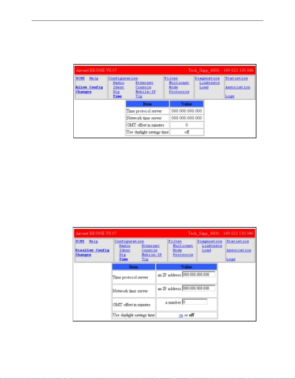
Setting up the Time Base (Configuration Time) ...........................................................6-5
Chapter 7 - Configuring Mobile IP
Using the Configuration Mobile IP Menu ...............................................................7-2
Setting the Agent Type (AgentType) ............................................................................7-2
Displaying the Active Clients (Mobile, Visitors) ..........................................................7-2
Authorizing Mobile Nodes to Roam (Add/Remove/Display) ......................................7-3
Set up the Agent Parameters (Setup) ............................................................................7-4
Control Agent Advertisements (Advert) .......................................................................7-5
Chapter 8 - Using the Spanning Tree Protocol
Overview ............................................................................................................................ 8-2
Understanding Loops .............................. .............. .............. ............................ ............. 8-3
How STP Protocol Works ................................................................................................... 8-4
Receiving Configuration Messages .................................................. ............................8-4
Determining the Root Bridge and Root Cost ................................................................8-5
Determining the Spanning Tree ....................................................................................8-6
Understanding Bridge Failures .....................................................................................8-6
Avoiding Temporary Loops ..........................................................................................8-6
Establishing Timeouts ............................................................ ...... .................................8-7
Node Address Aging .....................................................................................................8-7
Implementing STP Protocol ............................................................................................... 8-8
Using the Configuration STP Menu
(Root Bridge Only) ...................................... .........................................................................8-9
Setting Port Parameters (Port) .......................................................................................8-14
Displaying the Protocol Status (Display) ......................................................................8-16
Viewing the Port State (State) .......................................................................................8-17
Page 9

Contents v
Chapter 9 - Viewing Statistics
Viewing the Statistics Menu ............................................................................................... 9-2
Throughput Statistics (Throughput) ..............................................................................9-3
Radio Error Statistics (Radio) .......................................................................................9-4
Error Statistics ................................. ..............................................................................9-5
Displaying Overall Status (Status) ................................................................................9-7
Display a Network Map (Map) .....................................................................................9-8
Recording a Statistic History (Watch) ...........................................................................9-8
Displaying a Statistic History (History) ........................................................................9-10
Displaying Node Information (Node) ...........................................................................9-11
Displaying ARP Information (ARP) .............................................................................9-11
Setting Screen Display Time (Display_Time) ..............................................................9-12
Determine Client IP Addresses (Ipadr) .........................................................................9-12
Chapter 10 - Setting Up the Association Table
Overview ............................................................................................................................ 10-2
Using the Association Menu ...................................................... ......................................... 10-3
Displaying the Association Table (Display) .................................................................10-3
Displaying the Association Table Summary (Summary) ..............................................10-5
Setting the Allowed Number of Child Nodes (Maximum) ...........................................10-5
Controlling Associations With Static Entries (Autoassoc/Add/Remove) .....................10-6
Backbone LAN Node Stale Out Time (Staletime) ........................................................10-8
Specifying How Node Addresses are Displayed (NIDdisp) .........................................10-8
Chapter 11 - Using Filters
Overview ............................................................................................................................ 11-2
Using the Filter Menu ........ ................................................................................................. 11-2
Packet Direction (Direction) .........................................................................................11-2
Filtering Multicast Addresses (Multicast) .....................................................................11-3
Filtering Node Addresses (Node) .................................................................................11-5
Filtering Protocols (Protocols) ......................................................................................11-7
Page 10

vi Contents
Chapter 12 - Setting Up Event Logs
Overview ............................................................................................................................ 12-2
Information Logs ......................................................................................................... 12-2
Error Logs .................................................................................................................... 12-5
Severe Error Logs ........................................................................................................ 12-5
Using the Logs Menu ..................................... ..................................................................... 12-8
Viewing History Logs (History) ...................................................................................12-8
Clearing the History Buffer (Clear) ..............................................................................12-9
Specifying the Type of Logs to Print (Printlevel) .........................................................12-10
Specifying the Type of Logs to Save (Loglevel) ..........................................................12-10
Specifying the Type of Logs to Light Status Indicator (Ledlevel) ................................12-10
Setting Statistic Parameters (Statistics) .........................................................................12-11
Log Network Roaming (Network) ................................................................................12-12
Logging Backbone Node changes (BnodeLog) ............................................................12-12
Setting up SNMP traps (Snmp) .....................................................................................12-12
Forwarding Logs to a Unix System (Syslog,SysLevel,Facility,Rcvsyslog) ................. 12-14
Chapter 13 - Performing Diagnostics
Using the Diagnostics Menu ............................................................................................... 13-2
Testing the Radio Link (Linktest) .................................................................................13-2
Restarting the Unit (Restart) .........................................................................................13-2
Returning the Unit to the Default Configuration (Default, Reset) ................................13-2
Using the Network Menu ................. ................................................................................... 13-3
Starting a Telnet Session (Connect) ..............................................................................13-3
Changing the Escape Sequence (Escape) ......................................................................13-4
Physically Locating a Unit (Find) .................................................................................13-5
Sending a Ping Packet (Ping) ........................................................................................13-5
Loading New Firmware and Configurations (Load) .......................................................... 13-5
Downloading Using Xmodem Protocol (Xmodem/Crc-xmodem) ...............................13-6
Downloading or Uploading using the File Transfer Protocol (Ftp) ..............................13-7
Downloading Using the Internet Boot Protocol (Bootp/DHCP) ..................................13-10
Distributing Firmware or Configuration (Distribute) ...........................................13-12
Page 11

Contents vii
Appendix A -Aironet 340 Series Bridge Specifications
LAN Interfaces Supported .................................................................................................. A-1
Ethernet .........................................................................................................................A-1
Radio Characteristics .........................................................................................A-1
Physical Specifications ............................................................................ ........................... A-2
Console Port Pin-Out .......................................................................................................... A-3
Appendix B -Console Menu Tree
Appendix C -SNMP Variables
Appendix D - Cisco Technical Support
Appendix E -Regulatory Information
Manufacturer’s Federal Communication
Commission Declaration of Conformity Statement ............................................................ E-1
Professional Installation ........................................ ........................................................E-2
Department of Communications—Canada
Canadian Compliance Statement ........................................................................................ E-3
European Telecommunication Standards Institute
Statement of Compliance
Information to User ............................................................................................................. E-4
Page 12

viii Contents
Page 13

About the User’s Guide
This manual covers the installation, configuration, control, and
maintenance of your Aironet 340 Series Bridge.
Please read Chapter 1 – Installing the Aironet 340 Series Bridge before
attempting to install or use the hardware and software described in this
manual.
The user’s guide is arranged as follows:
Chapter 1 – Installing the Aironet 340 Series Bridge – Describes the
physical installation of the Aironet 340 Series Bridge.
Chapter 2 – Acces sing the Console System – Introduces you to the Con-
sole Port and shows you how to set up and configure the Console Port
parameters.
Chapter 3 – Before You Begin – Provides you with an overview of the
Configuration Menu and how to save and restore your configurations.
Chapter 4 – Configuring the Radio Network – Contains detailed
procedures for configuring your Radio Network.
About the User’s Guide - ix
Chapter 5 – Configuring the Ethernet Port – Contains detailed proce-
dures for configuring the Ethernet port.
Chapter 6 – Se tting Network Identifiers – Outlines the procedures for
setting the Aironet 3 40 Series Bridge’s Network Identifiers.
Chapter 7 – Configuring Mobile IP – Descr ibes how t o config ure th e
Aironet 340 Series Bridge for use with the Mobile IP Protocol.
Chapter 8 – Using the Spanning-Tree Protocol – Describes how to
configure the Aironet 340 Series Bridge for use with the Spanning Tree
Protocol.
Chapter 9 – Viewing Statistics – Describes how to use the Statistics
Menu to monitor the performance of the Aironet 340 Series Bridge.
Chapter 10 – Set ting Up the Association Table – Provides you with an
introduction to the association process and detailed procedures for
setting up the Aironet 340 Series Bridge’s Association Table.
Page 14

x Aironet 340 Series Bridge
Chapter 11 – Using Filters – D escribes how to control the forwarding of
multicast messages.
Chapter 12 – Set ting Up Event Logs – Out lines the procedures for set-
ting up Event Logs and lists the common error log messages received on
the Aironet 340 Series Bridge.
Chapter 13 – Performing Diagnostics – Provides you with detailed
procedures for restarting your unit, returning to your default configuration, and loading new fi rmware versions.
Appendi x A – Aironet 340 Series Bridge Specifications – Details the
Aironet 340 Series Bridge radio and physical specifications.
Appendi x B – Console Menu Tre e – Provides you with a listing of all
menus, sub-menus, and options contained in the Console Port.
Appendi x C – SNMP Variables – Lists the SNMP variables supported by
the Aironet 340 Series Bridge.
Appendi x D – Cisco Technical Support – Describes how to contact Cisco
for technical support.
Appendi x E – Regulatory Information – Provides the F CC, DO C, and
ETSI regulatory statements for the Aironet 340 Series Bridge.
Page 15

Typographical Conventions
When reading the user’s guide, it’s important to understand the symbol
and formatting conventions used in the documentation. The following
symbols and formatting are used in the manual.
Convention Type of Information
Bold type An action you must perform such as type or
Monospaced font Information and menus that are visible on the
About the User’s Guide - xi
Indicates a note which contains important
information set off from the normal text.
A caution message that appears before procedures which, if not observed, could result in
loss of data or damage to the equipment.
select.
Console Port screens.
Page 16

xii Aironet 340 Series Bridge
Welcome to the Aironet 240 Series Bridge
Welcome to the Aironet 340 Series Bridge
The Aironet 340 Series Bridge allows the connections of two or more
remote Ethernet LAN’s into a single virtual LAN. Workstations on each
of the remote LAN’s may communicate with each other as though they
were on the same physical LAN. The Aironet 340 Series Bridge can also
function as a Radio Access Point and provide transparent, wireless data
communications between the wired LAN (and/or within the Radio Network) and fixed, portable or mobile devices equipped with a wireless
adapter employing the same modulation.
Data Transparency and Protocols
The Aironet 340 Series Bridge transports data packets transparently as
they move through the Wireless Infrastructure.
The bridge is also protocol independent for all packets, exce pt those
either addressed specifically to the bridge or sent as multicast address
packets.
Depending on the address, packets will be processed as follows:
n All packets, except those either addressed specifically to the bridge
or sent as multicast address packets, will be processed without
examining the contents of the packet and without regard to the
protocol used.
n Packets addressed specifically to the bridge will be examined by
looking at the protocol header. If the protocol is recognized, the
packet will be processed.
n Multicast address packets will also be examined by looking at the
protocol header, but will be processed whether the protocol is
recognized or not.
Page 17

n If protocol filtering is enabled then the appropriate parts of the
packet will be examined.
Ethernet Compatibility
The Aironet 340 Series Bridge can attach directly to 10Base2 (Thinnet),
10Base5 (Thicknet) or 10BaseT (Twisted Pair) Ethernet LAN segments.
These segments must conform to IEEE 802.3 or Ethernet Blue Book
specifications.
If the existing infrastructure to which the bridge is to be attached is not
Ethernet-based, an Ethernet segment can be added by installing an
Ethernet Network Interface Card (NIC) in the File Server or by adding a
third-party bridge.
The bridge appears as an Ethernet node and performs a routing function
by moving packets from the wired LAN to remote workstations (personal computers, laptops and hand held computing devices) on the Wireless Infrastructure.
Aironet 340 Series Bridge xiii
Protocols Supported
Protocols supported:
n TCP/IP based protocol products
n SNMP Protocol – The resident agent is compliant with the MIB-I
and MIB-II standards, TCP/IP based internets, as well as a custom
MIB for specialized control of the system.
Radio Characteristics
The Aironet 340 Series Bridge uses a radio modulation technique known
as Direct Sequence Spread Spectrum transmission (DSSS). It combines
high data throughput with excellent immunity to interference. The
bridge operates in the 2.4 G Hz license-free I ndustrial Scientific and
Medical (ISM) band. Data is transmitted over a half-duplex radio channel operating at up to 11 Megabits per second (Mbps).
Page 18

xiv Aironet 340 Series Bridge
Radio Ranges
The following section provides general guidelines on factors that
influence infrastructure performance.
Site Survey
Because of differences in component configuration, placement, and
physical environment, every infrastructure application is a unique installation. Before installing the system, users should perform a site survey
in order to determine the optimum utilization of networking components
and to maximize range, coverage and infrastructure performance.
Here are some operating and environmental conditions that need to be
considered:
n Data Rates. Sensitivity and range are inversely proportional to data
bit rates. The maximum radio range is achieved at the lowest workable data rate. There will be a decrease in receiver threshold as the
radio data rate increases.
n Antenna Type a nd Placemen t. Proper antenna configuration is a
critical factor in maximizing radio range. As a general guide, range
increases in proportion to antenna height.
For a detailed explanation of antenna types and configurations along
with guidelines on selecting antennas for specific environments, see the
Aironet Antenna Guide, document number 710-003725.
n Physical Environments. Clear or open areas provide better radio
range than closed or filled areas. Also, the less cluttered the work
environment, the greater the range.
n Obstructions. A physical obstruction such as shelving or a pillar
can hinder the performance of the bridge. Avoid locating the computing device and antenna in a location where there is a barrier
between the sending and receiving antennas.
n Building Materials. Radio penetration is greatly influenced by the
building material used in construction. Fo r example, drywall construction allows greater range than concrete blocks.
Page 19

Line of Site
A clear line of sight must be maintained between wireless bridge antennas. Any obstructions may impede the performance or prohibit the ability of the wireless bridge to t ransmit and receive data. Directional
antennas should be placed at both ends at appropriate elevation with
maximum path clearance.
Security Features
The Aironet 340 Series Bridge employs Spread Spectrum Technology,
previously developed for military “anti-jamming” and “low probability
of intercept” radio syste ms.
The Aironet 340 Series Bridge must be set to the same System Identifier
(SSID) as all other Aironet devices on the wireless infrastructure. Units
with a different SSID will not be able to directly communicate with each
other.
Aironet 340 Series Bridge xv
Terminology
When configuring your system, and when reading this manual, keep in
mind the following terminology:
Infrastructure – The wireless infrastructure is the communications sys-
tem that combines Aironet bridges, mobile nodes and fixed nodes. Aironet bridges within the infrastructure can be either root units, which are
physically wired to the LAN backbone, or can act as wireless repeaters.
Other RF enabled devices serve as fixed nodes or mobile nodes.
Root Unit – The root unit is an Aironet bridge that is located at the top,
or starting point, of a wireless infrastructure. The root bridge is usually
connected to main wired backbone LAN. Since the radio traffic from the
other bridges LANs will pass through this unit, the root unit is usually
connected to the LAN which originates or receives the most traffic
Repeater – A repeater is an Aironet bridge that establishes a connection
to the root bridge or another repeater bridge to make the wired LAN to
which it is connected part of the bridged LAN.
End Node – A radio node that is located at the end of the network tree.
Page 20

xvi Aironet 340 Series Bridge
Parent/Child Node – Refers to the relationsh ips between node s in the
wireless infrastructure. Th e complete set of rel ationships is s ometimes
described as a network tree. For example, the Aironet bridge (at the top
of the tree) would be the parent of the end nodes. Conversely, the end
nodes would be the children of the Aironet bridge.
Association – Each root unit or repeater in the infrastructure contains an
association table that controls the routing of packets between the bridge
and the wireless infrastructure. The association table maintains entries
for all the nodes situated below the Aironet bridge on the infrastructure
including repeaters and radio nodes.
Power Saving Protocol (PSP) and Non-Power Saving Protocol –
The Power Saving Protocol allows computers (usually portable computers) to power up only part of the time to conserve energy. If a radio node
is using the Power Saving Protocol to communicate with the infrastructure, the Aironet bridge must be aware of this mode and implement additional features such as message store and forward.
Bridge System Configurations
The Aironet 340 Series Bridge can be used in a variety of infrastructure
configurations. How you configure your infrastructure will determine
the size of the microcell, which is the area a single bridge will provide
with RF coverage. You can extend the RF coverage area by creating multiple microcells on a LAN.
Examples of some common system configurations are shown on the
pages that follow, along with a brief description of each.
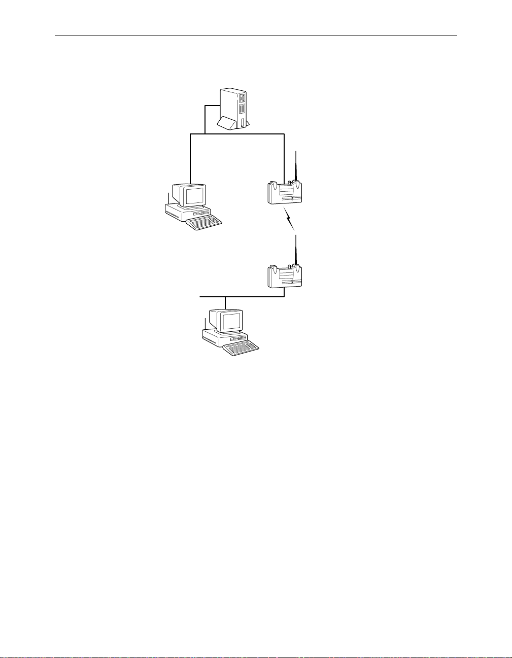
Point-to-Point Wireless Bridge
The Point-to-Point Wireless Bridge Configuration uses two units to
bridge two individual LANs. Packets are sent between the file serv er and
Workstation B through the wireless bridge units (root unit and remote
node) over the radio link. Data packets sent from the file server t o Workstation A go through the wired LAN segment and do not go across the
wireless radio link.
Page 21
Aironet 340 Series Bridge xvii
Figure 0.1 - Point-to-Point Wireless Bridge
File Server
LAN Segment A
Root Unit
(Wireless Bridge)
Workstation A
Remote Node
LAN Segment B
(Wireless Bridge)
Workstation B
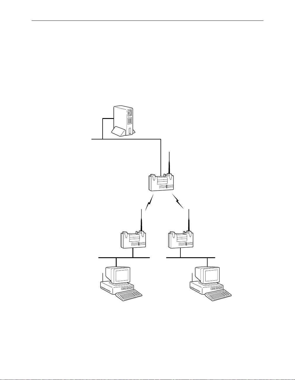
Point-to-Multipoint Wireless Bridge
When connecting three or more LANs (usually in different buildings),
each building requires an Aironet wireless bridge and antenna. This is
called a Multipoint Wireless Bridge Configuration. One wireless bridge
is designated as the central site. Its antenna is configured to transmit and
receive signals from the wireless bridges at the other sites. Generally,
the central site is equipped with an omni-directional antenna that provides radio signal coverage in all directions. The other wireless bridges
are typically served by directional antennas that direct radio signals
toward the central site.
Under a Multipoint Wireless Bridge Configuration, workstations
on any of the LANs can communicate with other workstations or
with any workstations on the remote LANs.
Page 22
xviii Aironet 340 Series Bridge
The following example shows an example of a Point-to-Multipoint Configuration. Packets sent between Workstation A and
Workstation B are forwarded by their respective wireless
bridges to the root unit. Then the root unit forward s these packets to the appropriate wireless bridge for routing to the workstations. Packets sent between the file server and the remote
workstations are routed through the root unit and the appropriate wireless bridge.
Figure 0.2 - Point-to-Multipoint Wireless Bridge
File Server
LAN Segment A
Root Unit
Wireless
Bridge
Workstation A Workstation B
Wireless
Bridge
LAN Segment CLAN Segment B
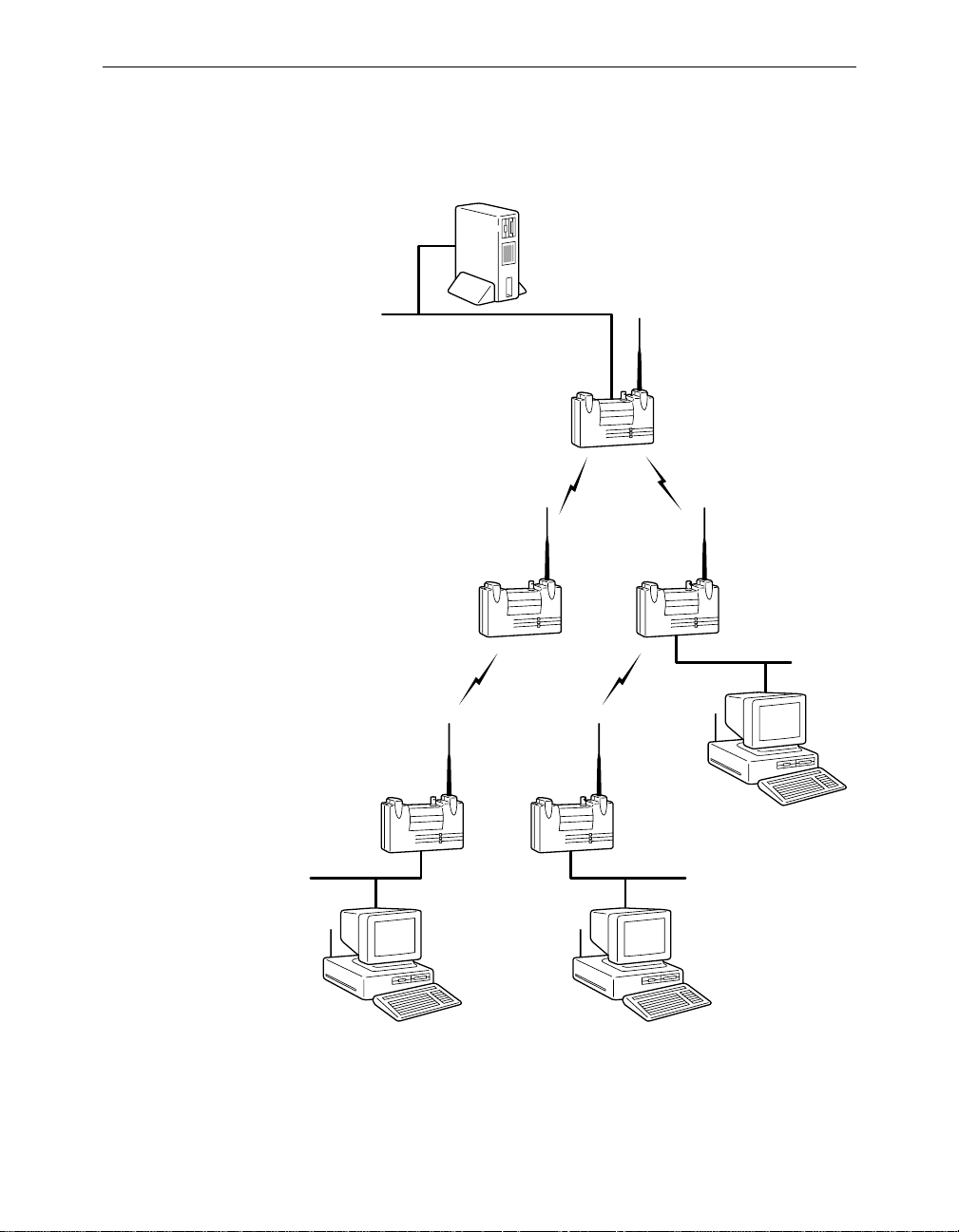
Infrastructure Extension with Repeaters
Wireless bridges can be configured as repeaters to extend the range of a
wireless network beyond that of a single radio hop. Repeaters can
Page 23
Aironet 340 Series Bridge xix
A
operate as either stand-alone units or have LAN connections.
Figure 0.3 - Infrastructure Extension with Repeaters
File Server
LAN Segment A
Root Unit
Repeater Repeater
Remote
Node
LAN Segment B
Remote
Node
LAN Segment C
Workstation CWorkstation B
LAN Segment D
Workstation
Page 24

xx Aironet 340 Series Bridge
Page 25

Part 1 - Getting Started
Part 1 - Getting Started
Page 26

Part 1 - Getting Started
Page 27

Chapter 1 - Installing the Aironet 340 Series Bridge
CHAPTER 1
Installing the Aironet 340 Series Bridge
This chapter describes the procedures for installing the Aironet 340
Series Bridge.
1
Here’s what you’ll find in this chapter:
n Before You Start
n Installation
n Installing the Antennas
n Installing the Console Port Cable
n Installing the Ethernet Connection
n Attaching the AC /DC Power Pack and Powering On the
Aironet 340 Series Bridge
n Viewing the Indicator Displays
Page 28

1 - 2 Aironet 340 Series Bridge
Befor e You Start
After unpacking the system, make sure the following items are present
and in good condition:
n Aironet 340 Series Bridge
n Power Pack. The power pack will be either 120VAC/60 Hz or
90-264VAC/47-63Hz to 12-18VDC, whichever is appropriate for
country of use.
n Lightning Arrestor (Bridge Package option)
n Mounting Kit (Bridge Package option)
n Low loss antenna cable (Bridge Package option)
n Appropriate directional antenna (Bridge Package option)
If any item is damaged or missing, contact your Aironet supplier. Save
all shipping and packing material in order to repack the unit should
service be required.
Figure 1.1 - Overview of the Aironet 340 Series Bridge
10BaseT (Twisted
Pair Ethernet)
Top Panel LEDs
10Base5
(AUI Port)
10Base2 (BNC
T-Connector)
Antenna
Connector
Console Port
RS-232 (DB-9
Female)
AC/DC Power
Pack Unit
On/Off Button
Page 29

Installation
Installing the Antennas
Before installing your bridge system, we recommend that you test the
bridge using the 2.2 dBi dipole antenna included in your package.
Once testing is completed, install your wireless bridge for use with
the appropriate antenna for your application using the following the
instructions.
1. With the unit powered off, attach the lightening arrestor to the
antenna connector.
Installing the Aironet 340 Series Bridge 1 - 3
Figure 1.2 - Attaching the Antenna
10Base5
10Base2
NOTE: Do not over-tighten; fin ger tight is suf ficient. Position the ante nna
vertically for best omni-di rectional sign al reception.
10BaseT
Page 30

1 - 4 Aironet 340 Series Bridge
2. Connect the lightning arrestor to one end of the low loss antenna
cable.
NOTE: The lightning arrestor should be connected to the antenna con-
nector on the wireless bridge. The lightning arrestor is added to provide
surge protection to the bridge in the event of voltage surges as a result of
a lightning strike.
3. Connect the antenna to the other end of the low loss antenna cable.
Mount the bridge antenna at an appropriate elevation to ensure maximum path clearance and line of sight considerations.
NOTE: Due to FCC and DOC Regu lations, t he ant enna con nectors on
the Aironet 340 Ser ies Bridge are of reverse polarity to the standard TNC
connectors.
Page 31
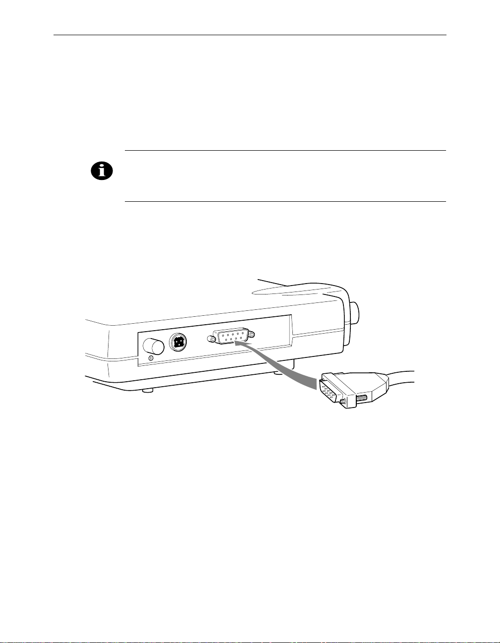
Installing the Console Port Cable
1. Attach the Console Port cable to the Serial Port. Attach the other
cable end to the Serial Port on a terminal or a PC running a terminal
emulation program. Use a 9-pin male to 9-pin female straight
through cable (Figure 1.3).
NOTE: This connection is r equire d for setting up init ial co nfigurat ion in formation. After configura tion is complete d, this cable may be removed until
additional config uration is requ ired via the Ser ial Port.
Figure 1.3 - Console Port Connection
Installing the Aironet 340 Series Bridge 1 - 5
2. Set the terminal to 9600 Baud, No-Parity, 8 data bits, 1 Stop bit, and
ANSI compatible.
Page 32

1 - 6 Aironet 340 Series Bridge
Installing the Ethernet Connection
The Aironet 340 Series Bridge supports three connection types:
n 10Base2 (Thinnet)
n 10Base5 (Thicknet) AUI connector
n 10BaseT (Twisted Pair)
Í To Attach 10Base2 (Thinnet) Cabling:
1. Make sure the unit is powered off.
2. Attach the Thinnet cabling to each end of a BNC T-connector,
if applicable.
3. Attach the T-c onnector to the 10Base 2 BNC (Figure 1.4). If the unit
is at the end of the Ethernet cable, a 50-Ohm terminator must be
installed on the open end of the T-connector.
Figure 1.4 - Attaching 10Base2 (Thinnet) Cabling
10Base2
10Base5
CAUTION: Removing a t erminato r to install extra cable, or breaking an
existing cable to install a T-c onnector, will cause a disrup tion in Ether net
traffic. Consult with your LAN administrator before you chang e any
Ethernet c abling co nnection s.
10BaseT
Page 33

Installing the Aironet 340 Series Bridge 1 - 7
Í To Attach the 10Base5 (Thicknet) Cabling:
1. Make sure the unit is powered off.
2. Attach the transceiver connector to the 10Base5 AUI port as shown
in Figure 1.5.
3. Slide the locking mechanism in place.
4. Attach the other end of the transceiver drop cabling to an external
transceiver.
Figure 1.5 - Attaching 10Base5 (Thicknet) Cabling
10Base2
10Base5
10BaseT
Í To Attach the 10BaseT (Twisted Pair) cabling:
1. Make sure the unit is powered off.
2. Plug the RJ-45 connector into the 10BaseT (Twisted Pair) port as
shown in Figure 1.6 .
3. Connect the other end of the Twisted Pair cabling to the LAN
connection (such as a hub or concentrator).
Figure 1.6 - Attaching 10BaseT (Twisted Pair) Cabling
10Base2
10Base5
10BaseT
Page 34

1 - 8 Aironet 340 Series Bridge
Attaching the AC/DC Power Pack and Powering On the Aironet 340 Series Bridge
1. Insert the small plug on the end of the AC/DC power pack cord into
the power port.
2. Plug the AC/DC power pack into an electrical outlet.
(120VAC/60 Hz or 90-264VAC as appropriate)
3. Power on the Aironet 340 Series Bridge by pushing the On/Off
button.
Figure 1.7 - AC to DC Power Pack Connections and On/Off Button
On/Off Button
When power is initially applied to the bridge, all three indicato rs will
flash in sequence to test the functionality of the indicators.
Page 35

Installing the Aironet 340 Series Bridge 1 - 9
Vi ewing the Indicator Displays
Top Panel Indicators
The indicators are a set of displays located on the top panel of the
Aironet 340 Series Bridge.
n Ethernet Indicator – Used to indicate infrastructure traffic activity.
The light is normally off, but will flash green whenever a packet is
received or transmitted over the Ethernet interface.
n Status Indicator – Shows solid green when the bridge has accepted
a radio association.
n Radio Indicator – Used to indicate radio traffic activity. The light
is normally off, but will flash green whenever a packet is received or
transmitted over the radio.
When the Aironet 340 Series Bridge is initially powered up, all three
displays will flash amber, red and then green, in sequence. If a power-on
test fails, the status indicator will go sol id red and the unit will stop
functioning. See Ta ble 1.1 for a detailed explanation of the Top Panel
indicators.
Figure 1.8 - Top Panel Indicators
RadioStatusEthernet
Page 36

1 - 10 Aironet 340 Series Bridge
Table 1.1 - Top Panel Indicator Description
Type
Ethernet Status Radio
Indicator Display
Description
Nonassociated
Node
Operational Green Blinking
Blinking
Green
Error/Warning Blinking
Amber
Failure Red Red Red Software failure
Firmware
Upgrade
Blinking
Green
Green One or more nodes
Green
Green Transmitting/Receiving
Green Blinking
Amber
Green Transmit/Receive errors
Blinking
Amber
Red Flashing the firmware
No nodes associated
associated
Transmitting/Receiving
Radio packets
packets
Maximum retries/buffer
full occurred on radio
General warning, check
the logs
Page 37

Back Panel Indicators
The back panel indicators shown in Figure 1.9 are:
n 10BaseT polarity: Solid amber to indicate th e 10BaseT polar ity is
reversed. Check cable connections.
n 10BaseT active: Solid green to indicate the 10BaseT has been config-
ured as the active port.
n Ethernet Rx: Flashes green when an Ethe rnet packet has been
received.
n Ethernet Tx: Flashes green when an Ethernet packet has been
transmitted.
n 10Base2 active: Solid green to indicate the 10Base2 has been config-
ured as the active port.
n Packet Collision: Flashes amber to indicate a packet collision has
occurred.
Installing the Aironet 340 Series Bridge 1 - 11
Packet
Collision
10Base2
Figure 1.9 - Back Panel Indicators
10BaseT polarity
Ethernet Tx
10BaseT
10Base5
10BaseT active
Ethernet Rx
10Base2 active
Page 38

1 - 12 Aironet 340 Series Bridge
Page 39

Chapter 2 - Accessing the Console System
CHAPTER 2
Accessing the Console System
This chapter describes the methods used to access the C onsole system of
the Aironet 340 Series Bridge. This system contains all commands necessary to configure and monitor the operation of the unit.
2
Here’s what you’ll find in this chapter:
n Access Methods
n Using the Console
n Telnet Access
n Web Access
n About the Menus
n Using the Configuration Console Menu
n Monitoring of DTR Signal
Page 40

2 - 2 Aironet 340 Series Bridge
Access Methods
There are many ways in which you may configure and monitor the Aironet 340 Series Bridge. When the unit is powered up, basic configuration
must initially be performed by accessing the Console Serial Port. To
gain access through the Serial Port, the bridge must be connected to a
terminal or a PC running a terminal emulation program. See Chapter 1
“Installing the Aironet 340 Series Bridge”. Set th e terminal to 9600
Baud, No-Parity, 8 data bits, 1 stop bit, and ANSI compatible.
Once the bridge has been assigned an IP address, you may then access
the Console remotely usin g:
n Telnet protocol from a remote host or PC
n HTML browser, such as Netscape Navigator from a remote host
n Simple Network Management Protocol (SNMP) from a remote net-
work management station
Using the Console
The Console system is organized as a set of menus. Each selection in a
menu list may either take you to a sub-menu or display a command that
will configure or display information controlling the unit.
When the bridge is powered up, the main menu will be displayed.
Ma in Menu
Option Value Descrip tion
1 - Configuration [ menu ] - General configurat ion
2 - Statistics [ menu ] - Display statistics
3 - Association [ menu ] - Associat ion table maintenance
4 - Filter [ menu ] - Control packet fil tering
5 - Logs [ menu ] - Alarm an d log cont rol
6 - Diagnostics [ menu ] - Maintena nce and te sting command s
7 - Privilege [ write ] - Set priv ilege leve l
8 - Help - Introduc tion
Enter an option number or name
>
Page 41

Accessing the Console System 2 - 3
Each menu contains the following elements:
n Title Li ne : Contains the product name, firmware version and menu
name. It also contains the unique name assigned to the unit. See
Chapter 6 “Setting Ne twork Identifiers”.
n Option Column: Displays the menu options and option number.
n Value Column: Displays either the value as [menu] or displays the
current settings for the option. If the value is [menu], there are additional sub-menus avai lable.
n Description Column: Provides a brief description of each option on
the menu.
n Enter an Option Number or Name >: The cursor prompt used to
enter option numbers, names, or commands.
To select an item from the menu you may either enter the number displayed beside the selection, in which case you are immediately taken to
the selection, or you may type the name listed in the option column followed by a carriage return. If you use the name method, you only need
to enter enough characters to make the name unique from the other
selection names in the m enu.
Sub-Menus
When you are entering names or command information you may edit the
selection by using the BACKSPACE character to delete a single character or the DELETE character to delete the entire line.
If the selection you chose is a sub-menu, the new menu will be displayed. You may now either choose a selection from this menu or return
to the previous menu by pressing the ESCAPE key. If you want to
return to the Main Menu, type th e equal key (=) at the menu prompt.
Page 42

2 - 4 Aironet 340 Series Bridge
Commands and Information
If your selection is a command, you may be prompted for information
before it executes. Information may be one of the following types:
n Token: A list of one or more fi xed strings. To select a particular
token, you need only enter enough of the starting characters of the
token to allow it to be uniqu ely iden tified from t he charac ters of th e
other tokens in the list.
Enter one of [off, readonly, write] : w
You would need only enter: “o”, “r”, or “w” followed by a carriage
return.
n String: An arbitrary amount of characters. The prompt will indicate
the allowable size range of the string.
Enter a name of from 1 to 10 characters: “abc def”
If the string contains a space, enclose the string in quotation marks.
If you wish to enter an empty string, use two quotation marks with
nothing between them.
n Integers: A decimal integer. The prompt will indicate the range of
allowed values.
Enter a size between 1 and 100 : 99
hexadecimal integer – a number specified in hexadecimal using the
characters 0-9 and a-f or A-F.
Enter a hex number between 1h and ffh : 1a
n Network address: An infrastructure or MAC level address of 12
characters or less. Omit leading zeros when entering an address.
Enter the remote network address : 4096123456
n IP address: An internet address in the form of 4 numbers from 0-
255 separated by dots (.). Leading zeros in any of the numbers may
be omitted.
Enter an IP address : 192.200.1.50
Once all information has been entered the command will execute. If the
information entered changed a configuration item, the new value will be
displayed in the menus.
Page 43

Some configuration commands only allow the choice between two fixed
values. When the menu item is selected, the opposite value to the current value is chosen. For example, if the configuration item is only a
selection between on and off, and the current value is on, then selecting
the menu option will select the off value.
Some commands which have a severe effect on the operation of the unit
(such as the restart command) and will prompt to be sure you want to
execute the command.
Are you sure [y/n] :
If you enter anything other than a “y” or a “Y” the command will not be
executed.
If you are being prompted for information, you may cancel the command
and return to the menu by typing ESCAPE.
Commands That Display Information
There are several types of commands that display information to the
operator. All displays end with a prompt before returning back to the
menus. If nothing is entered at the prompt for 10 seconds, the display
will automatically refresh.
Accessing the Console System 2 - 5
n Single page non-statistical displays end with the following prompt.
Enter space to re-display, q[uit] :
Any character other than space will cause the display to exit.
n Single page statistical displays end wi th the following prompt.
Enter space to re-display, C[lear stats], q[uit] :
Entering a “C” (capital) will reset all stat istics to zero.
n Multiple page table displays end with the following prompt.
Enter space to redisplay, f[irst], n[ext], p[revious], q[uit] :
Parts of the prompt may or may not be present depending on the display. If you are not at the first page of the display, you may enter “f”
to return to the first page or “p” to return to the previous page. If
you are not at the last page you may enter “n” to go to the next page.
Page 44

2 - 6 Aironet 340 Series Bridge
Command Line Mode
Another way to move within the Console is to enter commands directly
from the Main Menu. Commands allow you to bypass the menu system
and go directly to any level sub-menu or option. Enter the list of submenus, command names, and information separated by space characters.
Example 1: To access the Radio Configuration Menu (located two submenus down):
1. At the Main Menu prompt type:
configuration radio
2. Press ENTER. The Radio Configuration Menu appears.
Example 2: To access the packet size option from the Radio Link Test
Menu (located three sub-menus down):
1. At the Main Menu prompt type:
configuration radio linktest size 25
2. Press ENTER and the Main Menu is re-displayed.
Telnet Access
Once the Aironet 340 Series Bridge has been assigned an IP address and
connected to the infrastructure, you may connect to the Console system
from a remote PC or host by executing the telnet command.
Once the connection has been made, the Main Menu will appear. The
menus function in the same way for both telnet access and Serial Port
connections.
Page 45

While a telnet session is in progress, you may not use the Console Port
to gain access to the menus. If any characters are entered, the foll owing
message is printed identifying the location of the connection.
If you enter a break sequence, the remote operator will be disconnected
and control of the Console is returned to the Console Port.
You may disable telnet access to the bridge with a menu configuration
command.
NOTE: If you are leaving telnet enabled, make sure you set passwords to
secure the Console. Se e “Enabling Linemode (Linemode) ”.
Web Access
Accessing the Console System 2 - 7
Console taken over by remote operator at 192.200.1.1
<use BREAK to end>
The Aironet 340 Series Bridge supports access to the Console system
through the use of an HTML browser. To start a connection use:
http://ip address of Aironet 340 Series Bridge/
The page displayed will show the general status of the unit:
Page 46
2 - 8 Aironet 340 Series Bridge
The top section of the each page contains a set of links to the various
sub-pages that allow you to configure and display the status of the unit.
The following is a sample configuration page
At the top left there is a “HOME” link which always returned to the
main page.
By default, the web pages to display so as to not allow any changes to
the configuration of the unit. This is done to try and prevent any inadvertent mouse clicks from changing the configuration. To change a configuration item you must first click on the “Allow Config Changes” link
in the top left corner. The page will be re-displayed in a form that allows
the changes. Once the changes have been completed you should click on
the “D isallow Config Changes” link to re-protect the configuartion.
Page 47

Accessing the Console System 2 - 9
Some configuration items are displayed as a list of fixed choices. The
currently active choice is displayed in bold and cannot be selected. The
other choices are displayed as links that may be activated by clicking on
them.
Other configuration items require the entry of some text. Enter the new
value in the text box and then hit “Enter” to s end the change to the AP
for processing.
For those commands that display pages of information, the prompts
function the same as those on the Console Port, except instead of having
to type characters to select the different options, the option is a hyperlink.
You may disable web access to the bridge with a menu configuration
command.
NOTE: If you are leaving web access enabled, make sure that you set
passwords to secure the Console. See “Enabling Linemode (Linemode)”.
Page 48

2 - 10 Aironet 340 Series Bridge
About the Menus
Perform the following general functions using menus:
n Configuration: Allows you to configure Ethernet and Radio Param-
eters and establish Network Identifications. See Chapters 3-6.
n Statistics: View a variety of statistical information such as transmit
and receive data throughput, Ethernet and radio errors, and the general status of the Aironet 340 Series Bridge. See Chapter 9 “Viewing Statistics”.
n Association Table : A table that contains the addresses of all radio
nodes associated below the Aironet 340 Series Bridge on the infrastructure. You may use the association table to display, add and
remove static entries, and allow automatic additio ns to the table.
See Chapter 10 “Setting Up the Association Table”.
n Filter: Controls packet filtering. The filter menu allows you to con-
trol forwarding of multicast messages by blocking those multicast
addresses and protocols that are not used on the radio network. See
Chapter 11 “Using Filters”.
n Logs: Keeps a record of all events and alarms that occur on the unit.
With the Logs Menu, you can view and/or print a history of all log
entries, set alarm levels, and determine the type of logs you want to
save. See Chapter 12 “S etting Up Event Logs”.
n Diagnostics: Allows you to run link tests between the Aironet 340
Series Bridge and other infrastructure nodes to test the quality of the
radio link. Use the Diagnostics function to load new code versions
of the bridge’s firmware. See Chapter 13 “Performing Diagnos-
tics”.
n Privilege: Allows you to set privilege levels and passwords to
restrict access to the Console Port’s menus and functions.
n Help: A brief help screen outlining the procedures for accessing
menus and entering commands.
Page 49

Accessing the Console System 2 - 11
Using the Configuration Console Menu
The Console system is configured using the Configuration Console
Menu shown below. To access this menu, select Configuration from the
Main Menu then select Console from the Configuration Menu.
Config uration C onsole Menu
Option Value Descript ion
1 - Rpassword - Set read only privi lege password
2 - Wpassword - Set writ e privileg e password
3 - Remote [ on ] - Allow re mote opera tors
4 - Telnet [ on ] - Allow te lnet conne ctions
5 - Http [ on ] - Allow ht tp connect ions
6 - Display - Display the remote operator lis t
7 - Add - Add an o perator ho st
8 - Delete - Remove a n operator host
9 - Communities [ menu ] - SNMP com munity pro perties
01 - Type [ ansi ] - Terminal type
02 - Port [ menu ] - Serial p ort set-up
03 - Linemode [ off ] - Console expects co mplete lines
Enter an option number or name, “=” main men u, <ESC> prev ious menu
>_
Setting Privilege Levels and Passwords (Rpassword, Wpassword)
You can restrict access to the menus by setting privilege levels and passwords. Privilege levels are set from the Main Menu. Passwords are set
from the Configuration Console Menu.
There are three privilege levels:
n Logged Out Level (Off): Access denied to all sub-menus. Users are
only allowed access to the privilege and he lp options of the Main
Menu.
n Read-Only Level (Readonly): Read-only privileges for all sub-
menus. Only those commands that do not modify the configuration
may be used.
n Read-Write Level (Write): Allows users complete read and write
access to all sub-menus and options.
Page 50

2 - 12 Aironet 340 Series Bridge
Keep in mind the following when setting Privilege Levels and Passwords:
n Only Read-Only and Read-Write privilege levels can be password
protected.
n You can always go from a higher privilege level to a lower privilege
level without a password. If you try to go to a higher privilege level,
you will be required t o enter the password.
n Passwords are upper/lower case sensitive.
When Entering the passwords you will be prompted twice to ensure they
were entered correctly. The prompting will be done with echoing off.
To change the current privilege level go to the main menu and use the
“privilege” function. You will be prompted for the privilege level and its
associated password.
i
NOTE: After a privilege level has been assigned, anyone attemptin g to
access that level will be prompted for the password. This allows you to
set various privilege levels for individuals, providing them with acce ss to
some options, while denying them access to others. Remember passwords are case sensit ive.
CAUTION: Make sure you write down the passwords you have established and keep them in a safe place. If you forget your password, the unit
will have to be retur ned for factor y ser vicin g. Please contact Cisco Technical Suppor t for fur th er instr uctions.
Controlling Telnet and Web Access to the Console
You may disallow telnet and/or web access to the unit with the “telne t”
and “http” menu items. Setting the value to “off” completely disables
this type of access.
Page 51

Controlling SNMP access to the configuration
All SNMP management stations must include a community name string
in all of their requests for information of the unit. This string funct ions
as a password for the snmp access. Community names have either readonly or read/write access associated with them.
The read-only and read/write console passwords automatically are
allowed as SNMP community names with the appropriate privilege.
The “Configuration Console Communities” menu may be used to add
more community names for use by the network management stations.
Configuration Console Communities M enu
Option Valu e Des cription
1 - Display - Dis play SNMP com munities
2 - Add - Add a community
3 - Remove - Rem ove a communi ty
4 - Access - Set community ac cess mode
5 - Remote [ off ] - All ow remote NMS to change community in fo
Enter an option number or name, “=” main men u, <ESC> prev ious menu
>_
Accessing the Console System 2 - 13
You may use the “Add”, “Remove”, “Display” items to update and display the table of allowed community names. A newly added name will
by default only be allowed read-only access. To change the privilege
level of a community use the “Access” it em.
The “Remote” item is used to control whether a management station
with write access is allowed to change the community names.
By default the standard SNMP community names of “public”, “proxy”,
“private”, “regional” and “core” are allowed read-only access.
Page 52

2 - 14 Aironet 340 Series Bridge
Controlling Who Can Access the Console
You may also control access through the use of a table of remote users.
If a user is not in the table any remote access attempt will be terminated.
This table controls all remote access to the unit via telnet, http, ftp,
snmp, tftp, etc.
A user is identified by either IP address or the MAC address of t he host
he is using to attempt access . You may use the “Add”, “Rem ove”,
“Disp lay” items to update and display the table.
If the “Remote” item is set to “off” then all remote access is denied
regardless of entries in the table. If it is set to “on” and there are no
entries in the table then there are no restrictions on who may access the
console. If there are entries in the table then only those users whose IP
or MAC address match will be allowed access.words are case sensitive.
CAUTION: Remember that if you set remote off or make a mistake in the
table, the only acces s to t he consol e will be th rough the ser ial port.
Setting the Terminal Type (Type)
The terminal type item tells the unit whether the terminal or emulation
program you are using supports the ANSI escape sequences. Most modern ones do so you should select the “ansi” option. In this case colors
will be added to the displays and the screen cleared to start each new
page.
If the terminal does support the ANSI sequences but you do not want the
page to be cleared at the start of each display, choose the “color” option.
If the terminal or program does not support the ANSI sequences, you
should select “teletyp e” and no special formatting is done.
Page 53

Accessing the Console System 2 - 15
Setting the Communication Port Paramete rs (Port)
Use the port option to set the following Aironet 340 Series Bridge port
communication parameters: Baud Rate, Data Bits, Parity and Flow.
When the port option is selected, the Configuration Console Port Menu
appears. Any changes are effective immediately.
Confi guration Console Port Menu
Option Va lue Description
1 - Rate [ 96 00 ] - Console bau d rate
2 - Bits [ 8 ] - Bits per ch aracter
3 - Parity [ no ne ] - Console par ity
4 - Flow [ xon/ xoff ] - Flow contro l type
Enter an option number or name, “=” main men u, <ESC> prev ious menu
>_
n Baud rate selections include 300, 1200, 2400, 9600, 19200, 38400,
56800, or 115200 bits per second.
n Character size selection may be: 7 or 8 bits per character.
n Parity may be: even, odd, or none.
n Flow control selections include:
Off: No flow control. Input or output may be lost if the bridge cannot handle inputs or outputs from your terminal quickly enough.
Xon/Xoff: The bridge will use ASCII Xon/Xoff characters to con-
trol the input received from your terminal to prevent input buffer
overflow. The unit will also control its output of characters to the
terminal.
Hardware: The bridge will use the RTS and CTS lines to control the
flow of characters. The bridge sends characters while RTS is high
and will assert CTS when the terminal is allowed to send. This mode
is used for flow control by passing the Xon/Xoff characters. Make
sure the DTR signal is also present on the cable. S ee “Monitoring of
the DTR Signal”.
Both: Uses bot h hardwa re and X on/Xo ff flow cont rol.
Page 54

2 - 16 Aironet 340 Series Bridge
Enabling Linemode (Linemode)
Enable linemode when working with telnet and terminal emulators that
do not send characters when typed, but rather save them until the operator presses the carriage return at the end of a line.
The Console will not automatically complete any typed commands or
information when a space or carriage return is inserted.
To enable linemode:
1. Select Configuration on the Main Menu.
2. Select Linemode on the Confi guration Console Menu.
3. Enter “On” to enable line mode.
NOTE: Some telnet programs will automatically invoke linemode by sending the appropriate telnet commands when they connect to the Aironet
340 Series Br idge.
Page 55

Monitoring of the DTR Signal
The Aironet 340 Series Bridge monitors the state of the Data Terminal
Ready (DTR) signal. This signal is used to indicate the presence or
absence of a DTE device connected to the Console Port.
If the state of the signal changes (up or down) the following actions will
occur (unless a telnet session is in progress):
n Any currently executing command or display will be terminated
n Current menu will be returned to the Main Menu
n Console Privilege Menu will be set back to the highest level not
requiring a password.
If the Console is configured for hardwa re flow control and the DTR signal is currently down, all output will be discarded. The bridge would
assume flow is off and the Console would eventually lock up.
If the cable used does not have the DTR signal connected it will not
change state and no action will be taken.
Accessing the Console System 2 - 17
Page 56

2 - 18 Aironet 340 Series Bridge
Page 57

Part 2 - Configuration
Part 2 - Configuration
Page 58

Part 2 - Configuration
Page 59

Chapter 3 - Before You Begin
CHAPTER 3
Before Yo u Begin
This chapter provides a general introduction to the Confi guration Menu
and describes the procedures for saving and restoring your configurations. See Chapters 4 - 11 for more information on configurations.
3
Here’s what you’ll find in this chapter:
n Viewing the Configuration Menu
n Menu Descriptions
n Saving Configuration Parameters
n Backing up your Configuration
n Restoring your Configuration
Page 60

3 - 2 Aironet 340 Series Bridge
Viewing the Configuration Menu
Once you have completed the installation, the next step is to use the
Configuration Menu commands to configure the Aironet 340 Series
Bridge.
To acc ess the Configuration Menu, select Configur ation from th e Main
Menu.
Conf iguration Menu
Option Va lue Description
1 - Radio [ m enu ] - Radio networ k paramete rs
2 - Ethernet [ m enu ] - Ethernet con figuration
3 - Ident [ m enu ] - Identificati on informa tion
4 - Console [ m enu ] - Control cons ole access
5 - Stp [ m enu ] - Spanning Tre e Protocol
6 - Mobile-IP [ m enu ] - Mobile IP Pr otocol Con figuration
7 - Time [ m enu ] - Network Time Setup
8 - Dump - Dump configu ration to console
Enter an option number or name, “=” main men u, <ESC> prev ious menu
>_
Menu Descriptions
Radio: Used to set radio network parameters, such as system ID,
frequency, and bitrate. S ee Chapter 4 “Configuring the Radio
Network”.
Ethernet: Used to set the Ethernet Parameters. See Chapter 5 “Config-
uring the Ethernet Port”.
Ident: Used to set various infrastructure identifiers such as Node
Names, Network ID, and Internet Address. See Chapter 6 “Setting the
Network Identifiers”.
Console
Console System”.
STP: Used to configure the spanning tree protocol. See Chapter 8
“Using the Spanning Tree Protocol”.
Mobile-IP: Used to configure the unit as either a home or foreign
mobile P agent. See Chapter 7 “Configuring Mobile IP”.
: Used to set up the Console Port. See Chapter 2 “Accessing the
Page 61

Time: Used to configure time server address to set a standard time base
for displaying logs and alarms. See Chapter 6 “Setting the Network
Identifiers”.
: Used to dump the configuration commands to the Console Port.
Dump
See “Backing up your Configuration (Dump)”.
Saving Configuration Parameters
Although there is no explicit save command, your configuration parameters are automatically saved to non-volatile flash memory each time a
parameter is set or modified. This will ens ure the configuration is maintained during power failures or intentional pow er downs.
Most configuration settings become effective as soon as the command is
executed. Those that do not immediately become effective will be noted
in the command informatio n.
Backing up your Configuration (Dump)
Before You Begin 3 - 3
Once you have set the configuration parameters for the Aironet 340
Series Bridge, use the dump option to dump the configuration commands
to the Console Port and save them as an ASCII file on a diskette, using a
PC terminal emulation program.
If the non-volatile flash me mory should ever become corrupted (and you
lose your saved configuration), you can use a communications program
to send the configuration commands to the Console Port. The system
will automatically restore your configuration based on these commands.
Í To Back Up Configurations:
NOTE: Commands may var y depe nding on the communicat ions
program used.
1. In the terminal emulation program, set Save to File to On.
2. Select Configuration from the Main Menu then s elect Dump.
The following message appears:
Enter one of [all, non-default, distributable]:
Page 62

3 - 4 Aironet 340 Series Bridge
n All: The entire configuration will be displayed.
n Non-default: Only the configuration options that are different
from the original default settings will be displayed.
n Distributable: Only the configuration options that are not con-
sidered unique to this unit are displayed. You may use the “diag-
nostics load distribute” command to send this configuration to
other units in the infrastructure.
3. Enter one of [standard, encoded]:
n Standard: The configuration is displayed in normal readable
text form.
n Encode d: The configuration is displayed with each configura-
tion command replaced by a unique number. This type of configuration is the best to save since the number will never change
over the life of the product. Text may change or move as more
items are added to the menus .
4. Enter your configuration command choice.
5. Save the file after the commands have be en dumped.
6. Turn Save to File to Off.
7. Press any key to clear the screen.
Restoring your Configuration
If your configuration is ever lost or corrupted, you can use restore your
configuration using the program’s ASCII upload commands.
Page 63

Chapter 4 - Configuring the Radio Network
CHAPTER 4
Configuring the Radio Network
This chapter describes the procedures for configuring the Aironet 340
Series Bridge Radio Network. It describes all of the functions in the
“Configuration Radio Menu” and its sub-menus.
4
Here’s what you’ll find in this chapter:
n Setting up the basic radio configuration
n Setting up encrypt ion
n Setting up the advanced radio configuration
n How to test the radio links
Page 64

4 - 2 Aironet 340 Series Bridge
Overview
When configuring the radio network, all units should be configured
while in close proximity to each other. This will allow your units to
communicate with other radio nodes on your infrastructure as the units’
parameters are set.
Once configuration is complete, the units can then be move d to their
permanent location. Tests can be run to check the reliability of the radio
links. See “Running a Signal Strength Test (Strength)”.
The radio network parameters should be set in the order shown below:
1. Establish a system identifier.
2. Select a rate.
3. Select a frequency.
4. Enable root or repeater mode.
5. Set any extended parameters (optional).
CAUTION: Changing any of the radio para meters afte r you have com-
pleted your configuration s will cau se t he un it to dro p al l rad io conn ect io ns
and restar t wi th the changes you have made. Conseq uently, there will be
a disruption in rad io traffic throu gh the unit.
Page 65

Configuring the Radio Network 4 - 3
Using the Configuration Radio Menu
The radio network is configured using the Configuration Radio Menu.
To acce ss this menu, select Configuration from the Main Menu then
select Radio from the Configuration Menu.
C onfigurat ion Radio Men u
Option Value Descript ion
1 - Ssid [ "test" ] - Service set identi fication
2 - Root [ on ] - Enable r oot mode
3 - Rates [ 1_11 ] - Allowed bit rates in megabits/se con d
4 - Basic_rates [ 1 ] - Bas ic bit ra tes in megab its/second
5 - Frequency [ "auto" ] - Center f requency i n MHz
6 - Distance [ 0 ] - Maximum separation in kilometers
7 - I80211 [ menu ] - 802.11 p arameters
8 - Linktests [ menu ] - Test the radio lin k
9 - Extended [ menu ] - Extended parameter s
Enter an option number or name, “=” main men u, <ESC> prev ious menu
>_
Establishing an SSID (SSID)
This string functions as a password to join the radio network. Nodes
associating to the bridge must supply a matching value, determined by
their configurations, or their association requests will be ignored.
Enabling Root Mode (Root)
Use the root option to enable or disable root mode.
There may only be one unit serving as the root unit and it is usually con-
nected to the primary backbone infrastructure. Those acting as remote
bridges, attached to a secondary backbone and communicating via radio
to the root unit, should have their Root Mode set to “Off”. The default
setting is “On”.
Selecting the Allowed Data Rates (Rates)
Use the rate s option to define the data rate at which the unit is allowed
to receive and transmit information. Other units in the radio cell are
allowed to transmit data to us at any of th ese rates at their di scretion.
Page 66

4 - 4 Aironet 340 Series Bridge
When a repeater associates to a root unit data is usually transmitted
between the units at the highest rate that they both support. The units
may also downshift to use lower common rates if conditions warrant it.
Basic Rates (Basic_rates)
The basic rates option is set on the root bridge. It is the set of rates that
all nodes in the radio cell must support or they will not be allowed to
associate.
The lowest basic rate is use to transmit all broadcast and mul ticast traffic as well as any association control packets. Using the lowest rate
helps ensure they will be received by all nodes even at the farthest distances.
The highest basic rate determines the maximum rate at which an
acknowledge packet may be transmitted.
Selecting Frequency (Frequency)
The actual frequency allowed depends on the regulatory body that controls the radio spectrum in the location in which th e unit is used. If th e
setting is left as “auto”, t he unit will sample all the allowed frequencies
when it is first started and try to pick one that is not in use.
This setting is only allowed on the root unit as it is in charge of setting
up the radio cell
Setting the Distance (Distance)
Since the radio link between bridges can be quite long, the time it takes
for the radio signal to travel between the radios can become significant.
This parameter is used to adjus t the various timers used in the radio protocol to account for the extra delay.
The parameter is only entered on the root bridge, which will tell all the
repeaters. It should be entered as the distance in kilometers of the longest radio link in the set of bridges.
Page 67

Configuring the Radio Network 4 - 5
Using the Configuration Radio IEEE 802.11 Menu
Configu ration Ra dio I80211 Me nu
Option Value Descripti on
1 - Beacon [ 100 ] - Beacon p eriod in K usec
2 - Dtim [ 2 ] - DTIM int erval
3 - Extend [ on ] - Allow pr oprietary extensions
4 - Bcst_ssid [ on ] - Allow br oadcast SS ID
5 - Rts [ 2048 ] - RTS/CTS packet siz e threshold
6 - Privacy [ menu ] - Privacy configurat ion
7 - Encapsulation [ menu ] - Configur e packet e ncapsulation
Enter an option nu mber or n ame, “=” main menu, <ESC> previo us menu
>_
Setting the Beacon Period (Beacon)
The beacon interval is the time (in kilo-microseconds) between transmissions of the IEEE 802.11 beacon packet. The beacon packets are primarily used for radio network synchronization.
A small beacon period means faster response for roaming nodes. The
default value is typically adequate.
Setting the Forwarding Time Interval (DTIM)
The DTIM count determines the count of normal beacons between the
special DTIM beacons. If there no power saving client nodes in a cell, as
is usually the case with bridges, it is not used.
If there are power saving nodes present, the 802.11 protocol defines that
all power saving nodes must, at the minimum, wake up to receive the
DTIM beacons. If power save nodes are present, the AP will also buffer
any multicast packets it receives from the LAN and only transmit them
after the DTIM beacon.
Setting the DTIM count low causes t he multicasts to be tr ansmitted
more frequently, but sets a lower upper limit as to how long a power
save node may remain asleep.
Page 68

4 - 6 Aironet 340 Series Bridge
Adding IEEE 802.11 Management Packet Extensions (Extend)
If this parameter is enabled, th e Aironet 340 Series B ridge will add
extensions to some of the IEEE 802.11 management packets. This passes
more information to other radio nodes allowing them to associate to the
best bridge.
Even with the extensions enabled, other manufacturer’s nodes should
ignore the extra information. However, if they become confused, this
parameter may be disabled.
Allowing the Broadcast SSID (Bcst_ssid)
This option controls whether client nodes will be allowed to associate if
they specify the empty or broadcast SSID. Clients that do not know the
SSID of the bridge can transmit packets with the broadcast SSID. Any
bridges present will respond with a packet showing their SSID. The client will then adopt the SSID and associate.
If you wish to ensure that clients know the SSID beforehand then disable this function.
Setting the RF RTS/CTS Parameter (RTS)
This parameter determine s the minimum siz e transmitted packet th at
will use the RTS/CTS protocol. The value entered must be in the range
of 100 to 2048 bytes.
This protocol is most useful in networks where the mobile nodes may
roam far enough so the nodes on one side of the cell cannot hear the
transmission of the nodes on the other side of the cell.
When the transmitted packet is large enough, a small packet is sent out
(an RTS). The destination node must respond with another small packet
(a CTS) before the originator may send the real data packet. A node at
the far end of a cell will see the RTS to/from the bridge or the CTS to/
from the bridge. The node w ill k now how long to block its tran sm itter to
allow the real packet to be received by the bridge. The RTS and CTS are
small and, if lost in a collis ion, they can be retried mo re quickly and
with less overhead than if the whole packet must be retried.
Page 69

Configuring the Radio Network 4 - 7
The downside of using RTS/CTS is that for each data packet you transmit, you must transmit and receive another packet, which will affect
throughput.
Packet Encapsulation (Encapsulation Menu)
Configuration Radio I80 211 Encapsula tion Menu
Option Val ue D escription
1 - Encap [ 802. 1H ] - Default encap sulation m ethod
2 - Show - Show encapsul ation tabl e
3 - Add - Add a protoco l encapsul ation method
4 - Remove - Remove a prot ocol encap sulation meth od
Enter an option nu mber or n ame, “=” main menu, <ESC> previo us menu
>_
The Encap option and the related encapsulation table commands of
Show, Add and Remove are of concern only when both of the following
conditions exist:
n You are assembli ng a wireless LAN that incorporates non-Aironet
equipment.
n The non-Aironet equipment uses a proprietary method of packet
encapsulation that is different from the method used by Aironet.
If your wireless LAN consists only of Aironet components, use the
default Encap value of 802.1H and disregard the information in following discussion “Packet Encapsulation in Mixed Networks.”
Packet Encapsulation in Mixed Networks
Aironet LAN software allows you to assemble a wireless infrastructure
using components from different suppliers. When combining equipment
from different sources into a wireless LAN, you might need to accommodate different methods of packet addressing and conve rsion. The
complete subject of packet addressing is beyond the scope of this manual, and our purpose here is to provi de only basic guidelines and considerations.
To combine a mix of equipment from alternate suppliers into a wireless
LAN, you need to know the packet encapsulation methods used by the
different suppliers. If you determine that your infrastructure will be
mixing packet encapsulation methods, you will first need to determine
Page 70

4 - 8 Aironet 340 Series Bridge
your primary method, or standard, and choose that as the default setting
with the Encap option. All methods other than the primary, or default,
method need to be entered in the Encapsulation Table.
For all Aironet equipment, the defined packet encapsulation standard is
802.1H. The Show, Add and Remove options allow you to manage a
table of alternate, non-I802.1H encapsulation methods that might be
required to read data packets sent from the other, non-Aironet equipment. The primary alternate to the I802.1H standard is RFC 1042.
On an Ethernet LAN, the data portion of a frame may be in one of two
formats: DIX or DSAP/SSAP. The two formats differ both in packet size
specifications and in the manner of heading, or starting, the data portion. An 802 wireless LAN requires packets to start with the DSAP/
SSAP format and therefore must provide a method of conversi on. DSAP/
SSAP packet types are easily converted since the header is already in the
required style. DIX packet types present more of a problem since there
are many different formats and no standard conversion method.
Aironet’s 802.1H conversion protocol accommodates both DIX and
DSAP/SSAP packet types. In an 802.1H conversion, DIX type packets
are prepended with a header that mimics the DSAP/SSAP header. In an
Aironet infrastructure, this header style is not used by any wired Ethernet nodes so the remote radio node is always able to accurately reconvert the packet.
Page 71

Configuring the Radio Network 4 - 9
Packet Encryp tion (Privacy Menu)
Configuration Radio I80 211 Privacy M enu
Option Value Description
1 - Encryption [ off ] - Encrypt rad io packets
2 - Auth [ open ] - Authenticat ion mode
3 - Client [ open ] - Client auth entication modes allowe d
4 - Key - Set the key s
5 - Transmit - Key number for transm it
Enter an option nu mber or n ame, “=” main menu, <ESC> previo us menu
>_
This menu controls the use of encryption on the data packet transmitted
over the air by the radios. The packets are encrypted using the RSA RC4
algorithm using one of up to 4 known keys. Each node in the radio cell
must know all the keys in use, but they may select any one to use for
their transmitted data.
The “Key ” option is used to program the encryption keys into the radio.
You will be prompted as to which of the four keys you wish to set and
then you are prompted twice to enter the key with echoing disabled.
Depending on whether the radio is authorized to use 40 bit or 128 bit
keys, you must enter either 10 or 26 hexadecimal digits to define the
key.
NOTE: The keys must match in all nodes in the radi o cell and must be
entered in the same or der.
You do not need to define all four keys as long as the number of keys
matches in each radio in the cell.
Use the “Transmit” opt ion to tell the radio which of the keys it should
use to transmit its packets. Each radio is capable of de-crypting received
packets sent with any of the four keys.
If the “Encryp tion” option is set to “off” then no encryption is done and
the data is transmitted in th e clear. If the value is set to “on” then all
transmitted data packets will be en crypted and any un-encrypted
received packet will be discards.
Page 72

4 - 10 Aironet 340 Series Bridge
The “Encryption” value may also be set to “mixed’. In this mode a root
or repeater bridge will accept association from clients that have encryption turned on or off. In this case only data packets between nodes that
both support it will be encrypted. Multicast packets will be sent in the
clear so that all nodes may see them.
CAUTION: We do not recommend the use of “mixed” mode. If a client with
encryption ena bled sends a multicast packet to its par ent, the packet will
be encrypted . Th e p aren t w ill th en de crypt the packet and r e-tra nsmi t it in
the clear to the cell for the other nodes to see. Seein g a packet in both
encrypted a nd un-e ncr ypted form can gr eatly a id in b reaking a key. This
mode is only included for compatibil ity with other vendors.
The 802.11 protocol specifies a procedure in which a client must authenticate with a parent before it can associate. The “open” method of
authentication is esse ntially a null op eration . All cli ents will be allowed
to authenticate. With the “shared key” the parent send the client a challenge text which the client encrypts and sends back to the parent. If the
parent can de-crypt it correctly the client is authenticated.
CAUTION: With the “shared- key” mode, since a clear text and encry pted
version of the same data is transmitted on the air, we again do not recommend its use. It d oes not really ga in you anythin g, since i f the user’s key
is wrong the unit will not be able to de-crypt any of his packets and they
cannot gain access to the net work.
The “Clien t” option determines the au thentication mod e that the client
nodes are allowed to use to associate to the unit. The values allowed are
“open”, “shared-key”, or “both”.
The “Auth” is used on repeater bridges to determine which authentication mode the unit will use to connect with it s parent. The allowed values are “ope n” or “shared-key”.
Page 73

Configuring the Radio Network 4 - 11
Using the Configuration Radio LinkTests Menu
The options in this menu can be used to determine system performance
on individual nodes as well as individual node radio performance.
Configurat ion Radio Linktests Me nu
Option Value Descripti on
1 - Strength - Run a sig nal streng th test
2 - Carrier - Carrier b usy statis tics
3 - Multicast - Run a mul ticast ech o test
4 - Unicast - Run a uni cast echo test
5 - Remote - Run a rem ote echo t est
6 - Destination [ any ] - Target ad dress
7 - Size [ 512 ] - Packet si ze
8 - Count [ 100 ] - Number of packets t o send
9 - Rate [ auto ] - Data rate
01 - Errors - Radio err or statist ics
02 - Autotest [ once ] - Auto echo test
03 - Continuous [ 0 ] - Repeat ec ho test on ce started
Enter an option nu mber or n ame, “=” main menu, <ESC> previo us menu
>_
Running a Signal Strength Test (Strength)
The strength option sends a packet once per second to our parent access
point and each node in the association table. This packet is echoed back
to the Aironet 340 Series Bridge which records and displays the RF signal strength associated with that particular node.
It can be used to quickly check the link to each radio partner or could be
monitored while aligning directional antennas between two nodes. As
the antennas are moved, the signal strength could be monitored until the
maximum value is achieved.
SIGNA L LEVELS
BRxxxx 00409611d1e 5 Strengt h In ****** ********** ************* **
Out **************************** ******
(^C to exit) |----- ------ ---------- ------ -----|
Running a Carrier Busy Test
The Carrier option can be used to determine the amount of activity on
each of the available frequencies. Its main use is to pick an unused frequency or to check for the presence of a jammer.
Page 74

4 - 12 Aironet 340 Series Bridge
When started, the radio is put in a special mode, in which it will scan
through all the allowed frequencies, pause on each one and measure the
percentage of the time that the carrier detect line for the radio is busy.
CAUTION: Since this test uses a special operating mode all current associations to the unit wil l be lost dur ing the test.
CARRI ER BUSY / FRE QUENCY
*
*
*
* *
* *
* *
* *
* * *
* * *
* * * * * * * * * * *
1 1 2 2 3 3 4 4 5 5 6
2 7 2 7 2 7 2 7 2 7 2
Highest point = 9% utilizati on
Enter space to redi splay, q[ uit] :
The display is a scaled bar graph with the frequencies along the bottom.
The percentage utilization r epresented by the highest bar is given in the
bottom line.
Running the Echo Tests (Multicast, Unicast, Remote)
An echo test consists of sending a number of packet between units. The
packets are sent with a proprietary protocol, which the target nodes recognize and will echo back to the test source along with information
about how well it received the packets.
Page 75

Configuring the Radio Network 4 - 13
The multicast option is used to test transmis sion condi tions with in local
radio cells. Packets are sent between the source and destination nodes
without any acknowledgments or retries (as m ulticasts). This test provides a good indication of the raw state of the path to the node since no
attempt is made to recover from any radio errors.
Testing link to 004 09611d1e5 with 100 mul ticast pac kets of size 512
Please wait:
GOOD ( 9% Lost) Time Strength %
msec In Out
---- ----- ---- Sent: 100, Avg: 19 78 85
Lost to Tgt: 8, Max: 29 85 92
Lost to Src: 1, Min: 17 71 85
The time is displayed in milliseconds. Each packet contains the time it
was sent. When a packet is received by the source, the time difference
indicates the round trip time. Longer times indicate that the processor’s
or the radio’s bandw idth is full.
The signal strength numbers indicate the strength of the radio signal at
the time the packets were received at each end. Signal strength is
expressed as a percentage of full power.
The unicast option can be used to test the path between the Aironet 340
Series Bridge and any other Aironet node in the wired or radio network.
The packets are sent with the same error recovery as normal user data so
round trip times indicate the infrastructure throughput and congestion.
Testing link to 004 09611d1e5 with 100 uni cast packe ts of size 51 2
GOOD (8% Retries) Time Strength % Ret ries
msec In Out In Out
---- ----- ----- ---- --- Sent: 100, Avg: 25 78 85 Tot: 3 14
Lost to Tgt: 0, Max: 91 85 92 1 2
Lost to Src: 0, Min: 21 78 85 0 0
If the path to the target node was over the radio, a total number of radio
retries necessary to complete the test is also displayed. If the total number of retries is large, there may be problems with the link. Look for
Page 76

4 - 14 Aironet 340 Series Bridge
sources of interference.
Use the remote option to run a multicast link test between a client node
associated somewhere in the infrastructure and its parent bridge. You
will be prompted for the infrastructure address of the client node. A
broadcast request will be made. The bridge with this associated node
will run the link test and return the results which will be displayed to the
operator locally.
Remote linktest from 00409610d258 to 0040961064de
Sent 100 of 100 512 byte packets, Destination received 90, Source received 90
The Echo Test Parameters (Destination,Size,Count,Rate)
The destination option is used to indicate the target node address for the
link test. You may enter an infrastructure address or the string “any”. If
you select “any,” the Aironet 3 40 Se ries Br idge wil l di rect the tes t to th e
first legal address found in the association table, the access point to
which the unit is registered. If you enter a network address, it may only
be used for the remote or unicast linktests.
The size and count options are used to indicate the size and number of
packets to be sent. The default values are 100 packets of 512 bytes each.
Both the size and the count can be changed. The packet size may be set
from 24 to 1500 bytes and the count of the number of packets to transmit
may be set from 1 to 999 packets.
Using the rate option to control the data rate at which the packets are
sent. Normally you would leave t he setting at auto to allow the radio to
perform it’s normal rate shifting algorithm. You might use the actual
rate settings to test for the range limits at each of the data rates.
When running the link test, use the highest data bit rate possible to test
the reliability of your da ta bit rate and frequency combination. The more
packets you send and the larger the packet size, the more accurate the
test.
NOTE: Multiple large packets will increase test time.
Page 77

Configuring the Radio Network 4 - 15
Viewing Errors (Errors)
The errors option is used to view the Radio Error statistics that may
have occurred during the link test. See Chapter 9 “Viewing Statistics”.
Continuously Running a Link Test (Continuous)
The continuous option is used to continuously repeat the link tests. If
the value for the parameter is zero the tests are not repeated; otherwise,
the value determines the delay (in seconds) between tests.
Setting the Automatic Link Test Mode (Autotest)
The autotest option is used to control the automatic running of a link
test whenever a repeater associates to its parent. The test will use the
currently configured test parameters which, by default, runs a test to the
parent node.
n Off: An automatic test is never run.
n Once: Only one test is run the first time the unit associate s to a par-
ent after powering on.
n Always: The test is run each time the unit associates to a parent.
Page 78

4 - 16 Aironet 340 Series Bridge
During an automatic link test the three indicators on the unit will turn
green in a cyclic pattern to indicate a test is in progress. At the end of
the test, the indicators will be set to a solid pattern for 4 seconds to indiate the test results. The particular pattern that will be displayed depends
on the percentage of packets lost during the test as shown in Table 4.1
Table 4.1 - Auto Link Test Display Patterns
Radio Status Ethernet % of Packets Lost Quality
Green Green Green 0-2 Excellent
Green Green Amber 3-5 Very Good
Green Green Off 6-25 Good
Green Amber Off 26-50 Satisfactory
Amber Off Off 51-75 Fair
Red Off Off 76-100 Poor
The Autotest procedure can be used to help determine the placement of
repeater units. For example, at each prospective location, an installer
could cycle the power on the unit and watch the indicator displays for
the results of the link test. A s the test begins to fail, the instal ler could
determine the radio range to the infrastructure and adjust the location
accordingly.
Page 79

Configuring the Radio Network 4 - 17
Using the Configuration Radio Extended Menu
The extended radio parameters are not normally modified, but some may
have to be changed when certain situations a rise.
Confi guration Radio Extende d Menu
Option Value Descr iption
1 - Bridge_mode [ bridge_ only] - Bridg ing mode
2 - Parentid [ any ] - Paren t node Id
3 - Parent_timeout[ off ] - Time to lo ok for specified parent
4 - Time_retry [ 8 ] - Number of seconds to retry transmit
5 - Count_retry [ 0 ] - Maxim um number transmit retr ies
6 - Refresh [ 100 ] - Refresh rate in 1/10 of seconds
7 - Roaming [ direct ed ] - Type of roaming control pack ets
8 - Balance [ off ] - Load balancing
9 - Diversity [ off ] - Enabl e the dive rsity antenna s
01 - Power [ 20 ] - Trans mit power level
02 - Fragment [ 2048 ] - Maxim um fragmen t size
03 - Options - Enabl e radio op tions
Enter an option number or name, “=” main men u, <ESC> prev ious menu
>_
The Menu will display different options, depending on whether your
unit is serving as an infrastructure or a repeater.
Setting the Operating Mode (Bridge_mode)
This setting determines the type of client nodes that are allowed to associate to this unit. If it is se t to “bridge_only” then only other bridges are
allowed to associate and not any normal client nodes. Setting it to
“access_point” allowed any kind of client to associate. Setting the value
to “cli ent” on a repeater bridge will not allow any other nodes to associate to this node. Setting a repeater to client mode also reduces some of
the radio protocol overhead as this unit does not have to constantly
advertise its presence.
Selecting a specific parent (Parent_id, Parent_timeout)
The setting is only available on repeater bridges. Normally a radio node
will choose its parent by polling the air waves and choosing the best
available unit. If you wish to manually force a particular structure to the
Page 80

4 - 18 Aironet 340 Series Bridge
radio cell, usually because of knowledge of traffic patterns, you can use
the parent_id option to select the MAC address of the parent the unit
would always try and assoc iate to.
If you set the parent_timeout option to off the unit will only associate
with the specified parent. If you set a value, the unit will poll for the
specified parent for the given number of seconds each time it needs to
associate. If the parent is not found it will choose the best available parent. If the unit ever sees tha t the specified parent is p r esent it will switc h
its association.
Setting Retry Transmission Time (Time_Retries, Count_Retries)
These settings allow the user to establish a particular level of radio performance by controlling the RF packet retry level. The lesser of the two
values will be used. If the retry count is reached before the retry time is
met, then retry process on this particular packet is stopped. If the destination was a child node, it will be disassociated. If the destination was a
parent bridge, the unit will b egin scanning for a new parent.
The retry time may be set in the range of 1 to 30 seconds. The Aironet
340 Series Bridge will continually retry the packet in this time period
while contending for the air waves with other transmitting nodes.
The retry count may be set in the range of 0 to 64 times. If the count is
set to zero, only the retry time applies.
Use the retry count field if the Aironet 340 Series Bridge is mobile and
you want to move from bridge to bridge very quickly after moving out of
range. In non-mobile applications, since you can’t move out of range, it
is most likely there is some temporary inter ference. R etry at a later time.
Setting the Association Refresh Interval (Refresh)
This setting is only present on repeater bridges. If there has been no
directed traffic between the unit and its parent for the specified time (in
tenths of a second) the unit will send an empty packet to the parent to
verify that the connection is still alive.
Page 81

Roaming Notification Mode (Roaming)
When a node roams from one parent to another the new parent bridge
sends packets to the wired network to inform any other bridge, switches
and the old parent of the change in location.
If this option is set to di rected and if the client node knows its old parent’s address, this packet is sent as a directed packet to the old parent. In
all cases we have encountered this should update the other network
devices correctly. If you are having any problems you may wish to set
the option to broadcast to cause the packet to be sent as a broadcast and
be guaranteed to be sent everywhere in the network.
Setting the Loading Balance (Balance)
On a root bridge you may use the balance option to control how often
the repeater bridge will execute the load balancing algorithm (i80211
Extend must be enabled). The repeater bridges will search for better parents based on the data traffic load and number of association even if they
are having no trouble with their current parent. The options may be set
to Off, Slow (every 30 seconds), or Fast (every 4 seconds).
Configuring the Radio Network 4 - 19
Setting Diversity (Diversity)
This parameter tells the un it whether you have two antennas i nstalled.
Set the parameter to “Off” if one antenna is installed. The single antenna
must be installed on the right connector when facing the back of the unit
with the LED display facing up.
Setting the Power Level (Power)
This parameter may be used to reduce the power level of the radio transmitter down from the maximum allowed by the regulatory commission.
Depending on where you are located, you may be allowed to set the
power to 50 milliwatts, 100 milliwatts or to full power.
Setting Fragment Size (Fragment)
This parameter determines the largest packet size that may be transmitted. Packets that are larger than this size will be broken into pieces that
are transmitted separately and rebuilt on the receiving side.
Page 82

4 - 20 Aironet 340 Series Bridge
If there is a lot of radio interference or collisions with other nodes, the
smaller lost packets can be retried faster and with less impact on the airwaves. The disadvantage is if there is limited interference, long packets
will take more time to transmit due to the extra packet overhead and
acknowledgments for the fragments.
Set the fragment size between 256 and 2048 bytes.
Setting Purchasable Radio Options (Options)
This selection is used to enable s pecial features in th e radio that may be
purchased separately. One example is stronger encryption. To enable an
option select this menu item. You will be given the MAC address of this
unit and prompted for a password. Call customer support give them this
address and once payment has been verified you will be given the password for this unit.
Page 83

Chapter 5 - Configuring the Ethernet Port
CHAPTER 5
Configuring the Ethern et Port
This chapter describes the procedures for configuring the Ethernet Port of
the Aironet 340 Series Bridge.
5
Here’s what you’ll find in this chapter:
n Using the Configuration Ethernet Menu
n Activating/Disabling the Ethernet Port
n Setting the Maximum Frame Size and Port Interface Type
Page 84

5 - 2 Aironet 340 Series Bridge
Using the Configuration Ethernet Menu
The Ethernet Port is configured using the Configuration Ethernet Menu.
To acce ss this menu, select Configuration from the Main Menu then
select Ethernet from the Configuration Menu.
Configur ation Eth ernet Menu
Option Va lue Description
1 - Active [ on ] - Connection ac tive
2 - Size [ 15 18 ] - Maximum frame size
3 - Port [ au to ] - Port selectio n
Enter an option number or name, “=” main men u, <ESC> prev ious menu
>_
Activating/Disabling the Ethernet Port (Active)
NOTE: Do not activate the Ethernet Port unt il all other paramet ers have
been set correctly.
The active option is used to enable or disable the Ethernet Port connection. The default setting for active is “On”.
The active option should be disabled if the port on the Aironet 340
Series Bridge is not going to be used. This informs the software not to
route packets to the port and stops the use of processing powe r for scanning for Ethernet activity.
Setting the Maximum Frame Size (Size)
The size option allows you to increase the maximum size of the frames
transmitted to and from the Ethernet in frastructure. Do not set th e maximum frame size greater than 1518 unless you are running proprietary
software that allows you to exce ed this maximum. You may set the value
between 1518 to 4096.
Page 85

NOTE: After the parameter is changed, the unit must be restar ted eith er
by powe ri ng it “Off” an d then “On,” or by using t he “Diagnostics Restar t”
command for the chan ge to occu r.
Setting the Port Interface Type (Port)
If this parameter is s et to “Auto”, the A ironet 340 Series B ridge will
scan for a cable at all three connections. When the bridge is wired to an
Ethernet card that also scans, this parameter shoul d be set to the port
that is being configured. You may select AUI for 10base5 for thicknet,
10baseT for twisted pair, or 10base2 for coax and thinnet.
Configuring the Ethernet Port 5 - 3
Page 86

5 - 4 Aironet 340 Series Bridge
Page 87

Chapter 6 - Setting Network Identifiers
CHAPTER 6
Setting Network Identifiers
This chapter describes the procedures for setting the Aironet 340 Series
Bridge network id entifiers.
6
Here’s what you’ll find in this chapter:
n Setting the IP address, subnet mask, and routing tables
n Domain name server settings
n DHCP settings
n Setting the names assigned to the unit
n Setting up a time server
Page 88

6 - 2 Aironet 340 Series Bridge
Using the Configuration Ident Menu
Network identifiers are entered using the Configuration Ident Menu
shown below. To access this menu, select Configuration from the Main
Menu then select Ident from the Configuration Menu.
Con figuratio n Ident Menu
Option Valu e Descriptio n
1 - Inaddr [ 1 49.023.16 5.131 ] - Int ernet addr ess
2 - Inmask [ 2 55.255.25 5.000 ] - Int ernet subn et mask
3 - Gateway [ 1 49.023.16 5.050 ] - Int ernet defa ult gateway
4 - Routing [ menu ] - IP routing ta ble configura tion
5 - Dns1 [ 1 49.023.13 0.254 ] - DNS server 1
6 - Dns2 [ 0 00.000.00 0.000 ] - DNS server 2
7 - Domain [ "aironet. com" ] - Dom ain name
8 - Name [ " BR500T_24 c1e2" ] - Nod e name
9 - Location [ "" ] - Sys tem locati on
01 - Contact [ "" ] - Sys tem contac t name
02 - Bootp_DHCP [ on ] - Use BOOTP/DHC P on startup
03 - Class [ "BR500T " ] - DHC P class id
Enter an option number or name, “=” main men u, <ESC> prev ious menu
>_
Using DHCP or BOOTP
By default the unit is configured to attempt t o get a DHCP or BOOTP
server to assign it an IP address and optionally set other parts of the
configuration. For a complete description of this operation see “Down-
loading Using the Internet Boot Protocol (Bootp/DHCP)” in Chapter
13.
Assigning an IP Address (Inaddr)
Use the inaddr option to establish an IP (Internet Protocol) address for
the Aironet 340 Series Bridge. An IP address must be assigned to the
unit before it can be accessed by either telnet, HTTP, or SNMP.
Page 89

Setting Network Identifiers 6 - 3
Specifying the IP Subnet Mask (Inmask)
Use the inmask option to assign an IP Subnetwork mask to the Aironet
340 Series Bridge. The subnetwork mask determines the portion of the
IP address that represents the subnet ID. A digit in a “bit” of the mask
indicates that the corresponding “bit” in the IP address is part of the
subnet ID.
Setting Up the Domain Name Servers (Dns1,Dns1,Domain)
A domain name server allows the operator to specify the name of a
known host rather than its raw IP address when accessing another node
in the network You should obtain the address of the primary and backup
servers and well as the domain name for your network a dministrator.
Establishing a Node Name (Name)
The name option is used to establish a unique node name for the Aironet
340 Series Bridge. The name is a text string of up to 20 characters that
appears on all Console Port Menus. It is passed in associatio n messages
to other nodes on the radio network. See Chapter 10 “Se tting Up the
Association Table”.
Setting SNMP Location and Contact Identifiers (Location,Contact)
Use the location and contact options to specify the locat ion of the
SNMP workstation and the contact name of the individual responsible
for managing it in the event of problems.
You may enter an arbitrary string of up to 20 characters for each item.
Configuring the IP Routing Table (Gateway, Routing)
The IP routing table controls how IP packets originating from the bridge
will be forwarded. Once the destination IP address is determined the following checks are made:
1. If the destination IP address exactly matche s a host entry in the
table, the packet will be forwarded to the MAC address corresponding to the next hop IP address from the table entry.
Page 90

6 - 4 Aironet 340 Series Bridge
2. If the destination is in the local subnet, ARP is used to determine the
nodes MAC address.
3. If the destination address is on another subnet and matches the infrastructure portion of a net entry in the table (using the associated
subnet mask), the packet will be forwarded to the MAC address corresponding to the next hop IP address from the table entry.
4. If the destination address is on another subnet and does not match
any entry in the table, the packet will be forwarded to th e MAC
address corresponding to the default gateway’s IP address.
Most subnets only have one router which is alwa ys used to access the
rest of the network. Use the Gateway option to set the IP address of the
default router. This address is also used if the destination address does
not match any entries in the routing table described below.
The Routing options allows your to s et specific entries in the rou ting
table.
Config uration I dent Routing Menu
Option Valu e Descriptio n
1 - Display - Dis play route table entrie s
2 - Host - Add a static host route
3 - Net - Add a static network route
4 - Delete - Del ete a stat ic route
Enter an option number or name, “=” main men u, <ESC> prev ious menu
>_
Use the Host option to add an entry for a single host. You will be
prompted for the IP address of the host. Use the Net option to add an
entry for an external subnet. You will be prompted for a network address
and a subnet mask to identify the remote ne twork. Use the Delete opti on
to delete a table entry.
The Display options show the current table.
Routi ng Table
Destination Next Hop Mask Flags Use
---------------- ------- -------- --------- ------ ----- - ---
149.023.166.000 149.023 .165.071 255.255.2 55.000 S N 0
default 149.023 .165.050 000.000.0 00.000 S N 0
149.023.130.020 149.023 .165.060 255.255.2 55.000 S H 0
Page 91

Setting Network Identifiers 6 - 5
The Flags column displays letters identifying the type of entry:
n S: Entry is static (entered by operator)
n N: Entry is an remote network route
n H: Entry is a host route
The Use column indicates the number of packets that have been forwarded using this table entry.
Setting up the Time Base (Configuration Time)
This menu lets you configure the bridge to query a network time server
such that any logs its printed can reference the current date and time.
Con figuratio n Time Menu
Option Valu e Descripti on
1 - Time_server [ 149.023. 165.080 ] - Time prot ocol server
2 - Sntp_server [ 000.000. 000.000 ] - Network t ime server
3 - Offset [ -30 0 ] - GMT offse t in minutes
4 - Dst [ on ] - Use dayli ght savings time
>_
Enter an option number or name, “=” main men u, <ESC> prev ious menu
The time_server option sets the IP address or name of a unix time protocol server to be queried. The sntp_server option sets the IP address or
name of an internet simple network time protocol serve r to be queried.
You should configure only one type of server.
Since the time returned by the servers is based on Greenwich mean time
you must use the Offset option to give the time difference in minutes
(plus or minus) from GMT.
The Dst option selects whether your time zone uses daylight savings
time.
Page 92

6 - 6 Aironet 340 Series Bridge
Page 93

Chapter 7 - Configuring Mobile IP
CHAPTER 7
Configuring Mobile IP
This chapter describes how to set up the bridge to serve as a mobile IP
home or foreign agent. It assumes you understand the concepts and configuration necessary to use Mobile IP.
7
Mobile IP is a protocol that allows roaming across different IP subnets while
maintaining their original IP address. It requires a Mobile IP stack to be set up o n
the client device as well. This IP stack is available from FTP corporation and
other IP stack vendors.
Each client is assigned an IP address and a home agent IP address by the
network administrator. The Home agent resides on the subnet for which
the client’s IP address is local.
When the client roams to a foreign subnet, it contacts a foreign agent on
that subnet, supplying its home agent address. The foreign agent contacts the home agent with the client’s information. The home agent
begins relaying any packet found on its local LAN destined to the client’s IP address first back to the foreign agent and from there back to the
client.
Page 94

7 - 2 Aironet 340 Series Bridge
Using the Configuration Mobile IP Menu
C onfigurat ion Mobile-IP Menu
Option V alue Description
1 - AgentType [ o ff ] - Home / Forei gn Agent
2 - Mobile - Home Agent A ctive Mobi le Nodes
3 - Visitors - Foreign Agen t Visitor List
4 - Add - Add Mobile N odes
5 - Remove - Remove Mobil e Nodes
6 - Display - Display Home Agent Aut horized Addre sses
7 - Setup [ m enu ] - Agent Config uration
8 - Advert [ m enu ] - Advertisemen t Setup
Enter an option num ber or na me, "=" main menu, <ESC > previous me nu
>
Setting the Agent Type (AgentType)
Determine the type of agent the unit is configured for, Home or Foreign.
Setting this to OFF disables the Mobile IP processing.
Displaying the Active Clients (Mobile, Visitors)
On a home agent the Mobile option displays information about mobile
nodes that are currently away from their home network.
Mobile Node Care of A ddr Flags Lifetime
--------------- -- --------- ---- ------ --------
149.23.165.1 14 9.23.130. 20 SBDMGV 120/200
The first column displays the node’s IP address; the next shows the foreign agent it is connected with. The lifetime column displays the count
in seconds since this entry was refreshed and the count at which it will
be removed. To understand the meaning of the flags, you should read the
internet RFCs for Mobile IP. The flags have the following meanings:
n S - allow simultaneous care of addresses
n B - forwa rd broadcasts to the node
n D - send directly to the mobile node
n M - use minimum encapsulation method
n G - use GRE encapsulation method
n V - use Van Jacobsen compression
Page 95

Configuring Mobile IP 7 - 3
On a foreign agent the Visitors option display information about the
mobile nodes currently visiting this agent.
Mobile Node M ac Addres s Home Ag ent Sta te Lifetime
--------------- -- --------- - ---------- ----- --- -- --------
149.023.165.001 00 409612345 6 149.023.16 5.050 Est 180/200
The first column is the node’s IP address followed by its MAC address
and then its home agent IP address. The state is either established or
waiting for home agent c onfirmation. The lifetime colu mn displays the
count in seconds since this entry was refreshed and the count at which it
will be removed.
Authorizing Mobile Nodes to Roam (Add/Remove/Display)
Before a node is allowed to roam, the home agent must be told information about the node to validate its identity.
The Add option allows you to validate a range of IP addresses. You are
prompted for the low and high IP addresses in the range. They can be the
same address to validate a single user. You may require that the setup
packets sent between the home agent, foreign agent, and the node itself
must be encrypted. You can either enter noauthentication or a security
parameter index and an MD5 key.
The Remove option removes entries from the table. You may either
specify a single low IP address or all.
The Display option displays the currently authorized nodes.
Low Address High Ad dress S PI Md5 Key
--------------- ---- ------- ---- ------ ---- --- --------- ------- ---------
149.023.165.001 149.023. 165.002
149.023.165.010 14 9.023.165 .011 1 9000000 0000000000000 0000
Page 96

7 - 4 Aironet 340 Series Bridge
Set up the Agent Parameters (Setup)
This menu lets you configure the parameters that control the operation
of the agents.
Co nfigurati on Mobile-IP Setup Menu
Option Val ue De scription
1 - Lifetime [ 600 ] - Ma x Registra tion Lifetime
2 - ReplayProt [ timest amps ] - Re play Prote ction Method
3 - Broadcasts [ off ] - Br oadcast Fo rwarding
4 - RegRequired [ on ] - Re gistration Required
5 - HostRedirects [ off ] - En able ICMP Host Redirect s to MN
Enter an option num ber or na me, "=" main menu, <ESC > previous me nu
>
The Lifetime parameter has two functions. It is the maximum amount of
time the Home Agent will grant a mobile node to be registered on a foreign network before renewing its registration. Note that the lifetime a
mobile node asks for during the registration process may be more or less
than this value. However, the Home Agent will only grant a lifetime up
to this value.
The lifetime value is also placed in the agent advertisement packets.
mobile odes typically use this field from the advertisements to generate
the Lifetime value for the Registration Request.
The ReplayProt option determines the scheme used to prevent attacks
based on capturing packets and playing them back at a later time. Two
replay protection methods are allowed in Mobile IP: timestamps (mandatory) and nonces (optional). Due to a patent that may apply to nonce-
based replay protection, we do not support nonces at this time. This
value must be set to timestamps .
The Broadcasts option determines whether mobi le nodes are allowed to
request that broadcasts from their home network are forwarded via tunneling to the mobile node. Some protocols require broadcast packets
from the home network to maintain proper operation (i.e., NetBIOS).
Unless needed, this option should be left at the default value of off to
avoid unnecessary traffic.
If the RegRequired is off, mobile nodes are allowed the option of registering to a Home Agent without the use of a Foreign Agent via a colocated care-of-address dynamically acquired while on the foreign net-
Page 97

Configuring Mobile IP 7 - 5
work. This is useful in cases where Foreign Agents have not yet been
deployed on the foreign network; how ever, this scheme consumes IP
addresses on that network. Setting this value to on will force mobile
nodes on this network to always register using a Foreign Agent.
The HostRedirects
o ption indicates whether or not the Foreign Agent
will send an ICMP message to mobile nodes registered through it specifying the Address of an IP Router for the mobile node to use. If set to
“off” (default), the mobile node will always use the Foreign Agent as its
default gateway (router). Setting this value to “on” may improve performance while visiting a foreign network; however, there may be connectivity problems which result due to A RP broadcasts fr om the mobile
node.
Control Agent Advertisements (Advert)
Agents advertise themselves on the LAN so that the mobile nodes can
find them and determine whether they are home or away.
Co nfigurati on Mobile-IP Setup Menu
Option Val ue De scription
1 - AdvertType [ multic ast ] - Adv ertisement type
2 - AdvertInterval [ 5 ] - Adv ertisement interval
3 - PrefixLen [ off ] - Adv ertise pre fix length ex tension
4 - AdvertRtrs [ on ] - Adv ertise rou ters
Enter an option num ber or na me, "=" main menu, <ESC > previous me nu
>
The AdvertType value specifies the type of datagram the Mobile Agent
will use when sending out ICMP Agent Advertisements. The RFC 1256
recommendation and the default for the Access Point is to use the All
Hosts Multicast address (224.0.0.1). In testing, it was discovered that
some mobile nodes were no t automatically jo ining this multi cast group
and thus were ignoring the agent advertisements. For these mobile nodes
this value should be changed to ‘broadcast,’ which will use th e limited
broadcast address (255.255.255.255) for all unsolicited agent advertisements.
The AdvertInterval value specifies how frequently (in seconds) the
Mobile Agent will send out an ICMP Router Advertisement multicast.
These advertisements are used by the mobile nodes to locate the Mobile
Page 98

7 - 6 Aironet 340 Series Bridge
Agents and to determine to which network they are currently attached.
The more frequent the advertisement, the sooner the mobile node will be
aware that it has attached to a new network and start the registration/deregistration process (if necessary). Since these are either multicast or
broadcast datagrams (see below), the Access Point must be configured
to forward these types of frames onto the RF network. We are currently
working on a scheme to allow link layer notification of re-attachment
resulting in a Router Solicitation from the mobile node. This will
prompt a unicasted Router Advertisement from the Mobile Agent to the
mobile node and allow multicast/broadcast forwarding on the Access
Point to be turned off.
The PrefixLen option allows the Prefix Length extension to the Mobility Agent (router) advertisement to be enabled or disabled. This extension is used to indicate the number of bits in the subnet mask for the
Mobility Agent generating the advertisement. The presence of the Prefix
Length extension may be helpful to some mobile nodes in determining if
they have attached to a foreign network. The default value is off. (Note:
This option should be “on” for FTP TSR stacks and “off” for VxD
stacks.)
RFC 2002 (Mobile IP) states that IP Routers MAY be included in the
Router Advertisement (RFC 1256) portion of the Agent Advertisement.
However, since the IP Address of the Agent its elf is included in the
router list, doing so may cause some hosts to select the Mobility Agent
as its default router. In an attempt to minimize this situat ion, the M obile
Agent also includes the IP Address of its default router in the list of
advertised routers with a higher “preference” value. If a host continues
to select a Mobility Agent as its default router, the Agent can be configured to advertise zero routes by setting AdvertRtrs to “off”. The default
value is “on”.
Page 99

Chapter 8 - Using the Spanning Tree Protocol
CHAPTER 8
Using the Spanning-Tree Protocol
8
This chapter describes how to configure the Aironet 340 Series Bridge
for use with the Spanning Tree Prot ocol (STP) Protocol.
Here’s what you’ll find in this chapter:
n Overview
n Understanding Loops
n How STP Protocol Works
n Receiving Configuration Messages
n Determining the Root Bridge, Root Cost, and Spanning Tree
n Understanding Bridge Failures
n Avoiding Temporary Loops
n Establishing Timeouts
n Node Aging Addressing
n Implementing the STP Protocol
Page 100

8 - 2 Aironet 340 Series Bridge
Overview
STP is used to remove loops from a bridged LAN environment.
The Aironet 340 Series Bridge implements the IEEE 802.1d Spanning
Tree Protocol (STP) specification to manage multip le bridges in an
extended LAN environment. This allows the Aironet 340 Series Bridge
to be used in bridged infrastructures with other 802.1d compliant
bridges. The protocol also allows the bridges in an arbitrarily connected
infrastructure to discover a topology that is loop free (a tree) and make
sure there is a path between every pair of LANs (a spanning tree).
If you are administering a multiple-bridge infrastructure, this Chapter
explains how the protocol works. However, if your infrastructure consists of a single bridge you can operate with the default values, although
it might not be the optimal configuration required.
 Loading...