

Cisco BPX-BXM-155-8DX, BPX 8620, BPX-BXM-622, BPX-BXM-622-2D, BPX-BXM-622-2DX Installation And Configuration Manual
...Page 1

170 West Tasman Drive
San Jose, CA 95134-1706
USA
http://www.cisco.com
Cisco Systems, Inc.
Corpor ate Headq uarters
Tel:
800 553-NETS (6387)
408 526-4000
Fax: 408 526-4100
Cisco BPX 8600 Series
Installation and Configuration
Release 9.3.0
Jul y 200 1
Customer Order Number: DOC-7810674=
Text Part Number: 78-10674-01 Rev. D0
Page 2

TTHE SPECIFICATIONS AND INFORMATION REGARDING THE PRODUCTS IN THIS MANUAL ARE SUBJECT T O CHANGE WITHOUT
NOTICE. ALL STATEMENTS, INFORMATION, AND RECOMMENDATIONS IN T HIS MANUAL ARE BE LIEVED TO BE A CCURATE BUT ARE
PRESENTED WITHOUT WARRANTY OF ANY KIND, E XPRESS OR IMPLIED. USERS MUST TAKE FULL RESPONSIBILITY FOR THEIR
APPLICATION OF ANY PR ODUCTS.
THE SOFTWARELICENSE AND LIMITEDWARRANTY FOR THE ACCOMPANYING PRODUCT ARE SET FORTH IN THE INFORMATION
PACKET THAT SHIPPED WITH T HE PRODUCT AND A RE INCORPORATED HEREIN BY THIS REFERENCE. IF YOU ARE UNABLE TO
LOCATE THE SOFTWARE LICENS E OR LIMITED WARRANTY, CONTACT YOUR CISCO REPRESENTATI VE FOR A COPY.
The following information is for FCC c ompl i an ce of Class A devices: This equipment has been tested and found to comply with the limits for a Class A
digital device, pursuant to part 15 o f the FCC rules. These limits are designed to provide reasonable protection against harmful i nter fer enc e when the
equipment i s operated i n a commercial e nvi ronme nt . This equipment gen erat es, uses, a nd can ra di ate radio-fre quency energy and, if not inst all ed and us e d
in accordance with the ins t ruc tion manua l, may cause harmful interfer ence to radio communica tions. O per atio n of this equipment in a residential areais
likely to cause har mful inte rfere nce , in which case users will be required to c orrect t he inter ferenc e at their own expense.
The following information is for FCC compli ance of Class B devi ces: The equipment de scribe d in this manual generates and may radiat e radio-frequen cy
energy. If it is not installed in accordance with Cisco’s installati on instr ucti ons, it may cause interference with radio and television reception . This
equipment has be en tested and found to c ompl y with the limits for a Class B digital device i n accordance wit h the specifica tions in part 15 of the FCC rules.
These s pe cifi cations are designed to provi de reasonable protec tion agains t such interference i n a residential installati on. However , there is no guarantee
that interference will not occur in a particular installation.
Modifying the equipment without Cisco’s written authorizat ion may result in the equipment no longer complying with FCC requirement s for Class A or
Class B digit al devices. In that event, your right to use t he equipment may b e limited by FCC regulations, and you may be required to correct any
interference to radio or t ele vision communications at your own expense.
You can determine whet her yo ur equipment is causing i nterfe re nce by turning it off. If the int er fer ence s t ops, it was probably caused by the Cisco equipment
or one of its peripheral devices. If the equipment causes interf erenc e to radio or television reception, try to correct the interfe rence by using one ormore
of the follow in g measure s:
• Turn the televis ion or radio antenna until the interference stops.
• Move the equipm ent to one side or the other of the televisi on or radio.
• Move the equipm ent farther away from the television or radio.
• Plug the equipment into an outlet th at i s on a different circuit from the televis ion or ra dio. (That i s, make certa in the equi pmen t and the television orradio
are on circuits controlled b y d ifferent circuit breakers or fus es.)
Modifications to this product not a u thori zed by Cisco Systems, Inc. could void the FCC approval and negate your authority to operate the product.
The Cisco implementation of TCP header compression is an adaptation of a p rogra m developed by the University of Califo rnia, Berkeley (UCB) as part of
UCB’s public domain version of t he UNIX oper atin g system. All rights reserved. Copyri ght © 1981, Regents of the University of California.
NOTWITHSTANDING ANY OTHER WARRANTY HEREIN, ALL DOCUMENT FILES AND SOFTWAREOF THESE SUPPLIERS ARE PROVIDED
“AS IS” WITH ALL FAULTS. CISCO AND THE ABOVE-NAMEDSUPPLIERS DISCLAIM ALL WARRANTIES, EXPRESSED OR IMPLIED,
INCLUDING, WITHOUT LIMITATION,THOSE OF MERCHANTABILITY,FITNESS FOR A PARTICULARPURPOSE AND
NONINFRINGEMENT OR ARISING FROM A COURSEOF DEALING, USAGE, OR TRADE PRACTICE.
IN NO EVENT SHALL CISCO OR ITS SUPPLIE RS BE LIABLE FOR ANY INDI R ECT, SPECIAL, CONSEQUE NTIAL, OR INCIDENTAL
DAMAGES, INCLUDING, WITHOUT LIMITATION, LOS T PROFITS OR LOSS O R DAMAGE TO DATA ARISING OUT OF THE USE OR
INABILITY TO USE THIS MANUAL, EVEN IF CISCO OR ITS SUPPLIERSHAVE BEEN ADVISED OF THE POSSIBILITY OF SUCH DAMAGES.
AccessPath, AtmDirector, Browse with Me, CCIP, CCSI, CD-PAC, CiscoLink,theCiscoPowered Network logo, Cisco Systems Networking Academy,
the Ci sco Syst ems Networki ng Academy logo , Fast Step, Follow Me Browsing, FormSh are, FrameS har e, GigaStack, IGX , Internet Quoti ent, IP/VC, iQ
Breakthrough, iQ Expertise, iQ FastTrack, the iQ Logo, iQ Net Re adiness Sco recar d, MGX, the Networkers logo, Packet, RateMUX, ScriptBuilder,
ScriptShare, S lide Cast , SMARTnet, TransPath, U ni ty, Voice LAN, Wavelen gth Router, a nd WebViewer are tradema rks of Cis co Systems, Inc.; Cha ngi ng
the Wa y We Work, Live, Play, and Learn, Discover All That’s Possible, and Empowering the Internet Generation, are service marks of Cisco S ys tems,
Inc.; and Aironet, ASIST, BPX, Catalyst, CCDA, CCDP , CCIE, C CN A, CCNP, C i sco , the C isco Certified Internetwork Expert l ogo, Cisco IOS, the Cisco
IOS logo, Cisco Systems , Cis co Sys t ems Cap ital, the Cisco Systems logo, Ent er pris e/S ol ver, EtherChannel, EtherSwi tch, Fa stHub, FastSwitch, I OS, IP /TV,
LightStream, MICA, Network Registrar, PIX, Post-Rou ting, Pre -Routin g, Regis trar, StrataView Plus, Stratm, SwitchProbe, TeleRouter, and VCO are
registered trademarks of Cisco Systems, Inc. and/or its affiliates in the U.S. and c er tain other countri es.
All other tra dem ark s mentioned in this document or Web site are t he prope rt y of their respective owners. The use of the word partner does not i mpl y a
partnership relationship between Cisco and any other company. (0106R)
Cisco BPX 8600 Seri es Instal lation and Configurat i on, Releas e 9.3.0
Copyright © 2001 Ci s co Systems, Inc.
All rights r eserved.
Page 3

Cisco Reader Comment Card
General Information
1 Years of networkingexperience Years of experiencewith Ciscoproducts
2 I have these network types: LAN Backbone WAN
Other:
3 I have these Cisco products: Switches Routers
Other: Specify model(s)
4 I perform these types of tasks: H/W Install and/or Maintenance S/W Config
Network Management Other:
5 I use these types of documentation: H/W Install H/W Config S/W Config
Command Reference Quick Reference Release Notes Online Help
Other:
6 I access this informationthrough: Cisco Connection Online (CCO) CD-ROM
Printeddocs Other:
7 Which method do you prefer?
8 I use the following three product features the most:
Document Information
Document Title: Cisco BPX 8600 Series Installation and Configuration
Part Number: 78-10674-01 Rev. D0 S/W Release (if applicable): 9.3.0
On a scale of 1–5 (5 being the best) please let us know how we rate in the following areas:
Please comment on our lowest score(s):
Mailing Information
Company Name Date
Contact Name Job Title
Mailing Address
City State/Province ZIP/Postal Code
Country Phone ( ) Extension
Fax ( ) E-mail
Can we contact you further concerning our documentation? Yes No
You can also send us your comments by e-mail to bug-doc@cisco.com, or fax your comments to us a t
(408)527-8089.
The document was written at my
technical level of understanding.
The information was accurate.
The document was complete. The information I wanted was easy to find.
The information was well organized. The information I found was useful to my job.
% %
% %
Page 4

BUSINESS REPLY MAIL
FIRST-CLASS MAIL PERMIT NO. 4631 SAN JOSE CA
POSTAGE WILL BE PAID BY ADDRESSEE
ATTN DOCUMENT RESOURCE CONNECTION
CISCO SYSTEMS INC
170 WEST TASMAN DRIVE
SAN JOSE CA 95134-9883
NO POSTAGE
NECESSARY
IF MAILED
IN THE
UNITED STATES
Page 5

CONTENTS
iii
Cisco BPX 8600 Series Installation and Configurati on
Release 9.3.0, Part Number 78-10674-01 Rev. D0, July 2001
Preface xxxv
Document ation C D-R OM xxxv
Audience xxxvi
Cisco WAN Switching Product Name Change xxxvi
Related Documentation xxxvi
Conventions xxxvii
CHAPTER
1 The BPX Switch: Functional Overview 1-1
The BPX 8600 Series 1-1
BPX 8620 1-2
BPX 8650 1-3
BPX 8680 1-4
BPX 8680-IP 1-4
New with Release 9.3 1-4
Discontinued 1-6
BPX Switch Operation 1-6
The BPX Switch with MGX 8220 Shelves 1-7
Multiprotoc ol Label Switc hin g 1-7
Private Network to Network Interface (PNNI) 1-8
Virtual Private Networks 1-9
MPLS Virtual Privat e Net wo rks 1-9
Frame Relay to ATM Interworking 1-10
Network Interworking 1-11
Service Interworking 1-12
Tiered Networks 1-13
Routing Hubs and Interface Shelves 1-13
BPX Switch Routing Hubs 1-14
BPX Routing Hubs in a Tiered Network 1-15
Tiered Network Implementation 1-16
Tier Network Definitions 1-17
Upgrades 1-17
Network Management 1-18
Page 6

Contents
iv
Cisco BPX 8600 Series Installation and Configuration
Release 9.3.0, Part Number 78-10674-01 Rev. D0, July 2001
Inverse Multiplexing ATM 1-19
Virtual Trunking 1-19
Traffic and Congestion Management 1-20
Advanced CoS Manag em ent 1-21
Automatic Routing Management 1-22
Cost-Based Routing Management 1-22
Priority Bumping 1-22
ABR Standard with VSVD Congestion Control 1-23
Optimized Bandwidth Management (ForeSight) Congestion Control 1-23
Network Management 1-24
Cisco WAN Manager 1-25
Network Interfaces 1-26
Service Interfaces 1-27
Statistical Alarms and Network Statistics 1-27
Node Synchronization 1-27
Switch Software Description 1-28
Connections and Connection Routing 1-28
Connection Routing Groups 1-29
Cost-Based Connection Routing 1-30
Major Features of Cost-Based AutoRoute 1-30
Cost-Based AutoRoute Commands 1-31
Network Synchronization 1-32
Switch Availability 1-33
Node Redundancy 1-33
Node Alarms 1-33
CHAPTER
2 BPX Switch Physical Overview 2-1
BPX Switch Enclosure 2-1
Node Cooling 2-3
Node DC Powering 2-3
Optional AC Power Supply Ass embly 2-4
Card Shelf Configuration 2-5
BPX Switch Major Hardware Component Groups 2-5
Service Expansion Shelf PNNI 2-8
Optional Peripherals 2-8
Page 7

Contents
v
Cisco BPX 8600 Series Installation and Configurati on
Release 9.3.0, Part Number 78-10674-01 Rev. D0, July 2001
CHAPTER
3 BPX Switch Common Core Components 3-1
Broadband Controller Card (BCCs) 3-2
Features 3-3
Functional Description 3-3
Front Panel Description 3-5
19.2 Gbps Operation with the BCC-4V 3-7
Back Cards for the BCC-4V 3-7
Alarm/Status Monitor Card 3-11
Features 3-11
Functional Description 3-11
Front Panel Description 3-12
Line Module for the Alarm/Status Monitor Card 3-14
BPX Switch StrataBus 9.6 and 19.2 Gbps Backplanes 3-16
CHAPTER
4 BNI (Trunk) Cards 4-1
BPX Switch Network Interface Group 4-1
Broadband Network Interface Cards (BNI-T3 and BNI-E3) 4-2
Features 4-3
Functional Description 4-3
Bandwidth Control 4-5
Loopbacks and Diagnostics 4-5
Front Panel Indicators 4-6
T3 and E3 Line Modules (LM-3T3 and LM-3E3) 4-8
OC-3, Line Modules (SMF, SMFLR, & MMF) 4-10
Y-Cabling of BNI Backcard, SMF-2-BC 4-14
CHAPTER
5 BXM Card Sets: T3/E3, 155, and 622 5-1
Overview: BXM Cards 5-2
BXM Capabilities 5-4
ATM Layer 5-5
Service Types 5-5
Minimum SCR and PC R 5-6
Virtual Interfaces 5-7
Virtual Ports 5-7
Enhanced BXM 5-7
BXM Front Card Indicators 5-10
Page 8

Contents
vi
Cisco BPX 8600 Series Installation and Configuration
Release 9.3.0, Part Number 78-10674-01 Rev. D0, July 2001
BXM Backcard Connectors 5-13
Y-Cabling of SMF-622 Series Backcards 5-18
Automatic Protection Switching Redundancy 5-20
BXM Functional Description 5-22
Operation in Port (UNI) Mo de 5-22
Operation in Trunk Mode 5-24
Detailed Description of Port (UNI) and Trunk Modes 5-26
DRSIU 5-26
SONET/SDH UNI (SUNI) 5-27
DeMux/Mux 5-27
RCMP 5-27
SABRE 5-27
Ingress and Egress Queue Engines 5-28
SIMBA 5-28
ACP Subsystem Processor 5-28
Fault Management and Statistics 5-29
Port (UNI) Mode 5-29
Trunk Mode 5-30
Technical Spec ific ation s 5-30
Physical Layer 5-30
General Informa ti on 5-31
CHAPTER
6 Installation Overview 6-1
Summary: Installation Procedure 6-1
Installation Sequence Flow 6-2
Configuration: Lines, Trunks, and Connection 6-3
CHAPTER
7 Preliminary Steps Before Installing 7-1
Site Preparation 7-1
Parts Checklist 7-2
Safety Requirements 7-3
CEPT Requirements 7-3
EMI Requirements 7-3
Laser Safety Guidelines 7-3
Maintaining Safety with Electricity 7-4
Basic Guidelines 7-4
Page 9

Contents
vii
Cisco BPX 8600 Series Installation and Configurati on
Release 9.3.0, Part Number 78-10674-01 Rev. D0, July 2001
Power and Grounding 7-5
Mechanical Installation 7-6
Horizontal Positioning 7-6
Vertical Positioning 7-6
Installing a BPX Switch Shelf, Preliminary Steps 7-8
CHAPTER
8 Installation with Cisco Cabinets including 7000Series Routers 8-1
Installing a BPX Switch in a Cisco Cabinet 8-1
Preliminar y Procedu re : 8-2
Installing a 7200 or 7500 Router in a BPX 8650 Cabinet or Rack 8-6
Installing Router Assembly in a Cisco Cabinet 8-7
Installing Router Assembly in a 19-Inch Open Rack 8-8
Installing Router Assembly in a 23-Inch Open Rack 8-9
CHAPTER
9 Installation in Customer Cabinet 9-1
Installing a BPX Switch, Rear Rail Setback at 30-Inch 9-1
Preliminar y Procedu re : 9-1
CHAPTER
10 Installing the DC Shelf 10-1
DC Power Input Connections 10-1
Card Slot Fuses 10-4
Fan Power Fuses 10-5
CHAPTER
11 Installing the AC Shelf 11-1
Installing an AC Power Supply Tray 11-1
Installing an AC Power Supply 11-7
AC Power Input Connections 11-10
Card Slot Fuses 11-12
Fan Power Fuses 11-13
CHAPTER
12 Installing the T3/E3 Cable Management Tray 12-1
Installation of Cable Management Tray 12-1
Installing Tray Brackets 12-1
Installing Tray 12-2
Raising Tray for Access to PEMs 12-3
Installing BXM T3/E3 Cable Bracket 12-4
Page 10

Contents
viii
Cisco BPX 8600 Series Installation and Configuration
Release 9.3.0, Part Number 78-10674-01 Rev. D0, July 2001
Connecting Cables to BXM T3/E3 Cards 12-5
Routing Cables from Cards through Cable Management Tray 12-7
Tray Raised with Cables in Place 12-7
CHAPTER
13 Installing the BPX Switch Cards 13-1
Installing the Cards 13-1
Installing Front Cards 13-4
Installing Back Cards 13-6
Verifying 9.6 or 19.2 Gbps Backplane 13-7
Upgrading to BCC-4 Cards 13-9
Specifying Card Redundancy 13-9
Installation of APS Redundant Frame Assembly and Backcards 13-12
APS 1:1 Redundan cy Inst alla tion 13-12
APS 1+1 Redundancy Installation 13-13
CHAPTER
14 Connecting Cables 14-1
Making T3 or E3 Connectio ns 14-2
Making a BXM OC-3 or OC-12 Connection 14-4
Making a BXM T3/E3 Con nect ion 14-6
Setting up the BME OC-12 Port Loop 14-8
Alarm Output Connections 14-9
CHAPTER
15 Connecting Temporary Terminal and Attaching Peripherals 15-1
Temporarily Connecting a Terminal or NMS to the Control Port 15-2
Powering Up the Control Terminal 15-4
Connecting a Network Printer to the BPX Switch 15-7
Auxiliary Port Parameters for Okidata 184 Local Printer 15-7
DIP Switch Settings for Okidata 184 15-7
Procedure to Attach a Local Printer 15-8
Connecting Dial-In and Dial-Out Modems 15-10
Motorola V.34R BPX Switch Dial-In Configuration 15-11
BPX Switch Auto-Answer (Dial-In to BPX switch) 15-11
Auto -Dial to Cus t om e r S e r vi ce 15-13
Making Extern al Cloc k Conne ctio ns 15-16
Page 11

Contents
ix
Cisco BPX 8600 Series Installation and Configurati on
Release 9.3.0, Part Number 78-10674-01 Rev. D0, July 2001
CHAPTER
16 Checking and Powering-Up 16-1
BPX Switch Startup Diagnostic 16-2
Provisioning the BPX Switch 16-3
CHAPTER
17 Initial BPX 8600 Node Configuration 17-1
Summary of Configuration Procedures 17-1
Initial Node Configuration Summary 17-2
Command Sequences for Setting Up Nodes 17-4
Summary of Commands 17-5
CHAPTER
18 Configuring Trunks and AddingInterface Shelves 18-1
Configuring Tr unks 18-1
Setting Up a Trunk 18-2
Reconfiguring a Trunk 18-3
Removing a Trunk 18-5
Displaying or Printing Trunk Configurations 18-5
Adding an Interface Shelf 18-6
CHAPTER
19 Configuring Circuit Lines 19-1
Setting Up a Circuit Line 19-2
Flow Diagra m s for Li ne Se tup 19-3
Line Command s 19-4
CHAPTER
20 Configuring Network Management 20-1
LAN Connection for the Network Management Station 20-2
Configuring the BPX Switch LAN and IP Relay 20-3
Configuring the Cisco WAN Manager Workstation 20-5
Configuring the LAN Port 20-6
Controlling External Devices 20-10
CHAPTER
21 Configuring ATM Connections 21-1
ATM Connection Services 21-1
Basic ATM Connection Procedure 21-2
Traffic Management Overview 21-3
Standard Available Bit Rate 21-5
VSVD Description 21-5
Page 12

Contents
x
Cisco BPX 8600 Series Installation and Configuration
Release 9.3.0, Part Number 78-10674-01 Rev. D0, July 2001
BXM Connections 21-5
ForeSight Conge s tion Con trol 21-6
ATM Connection Requirements 21-6
Overview of Procedure to add ATM Connections 21-7
Connection Routing 21-7
addcon Command Syntax 21-8
addcon Example 21-8
ATM Connection Flow 21-10
ATM Connection Flow through the BPX 21-10
Advanced CoS Manag em ent 21-10
Connection Flow Example 21-11
Ingress from CPE 1 to BXM 3 21-11
Egress to Network via BXM 10 21-12
Ingress from Network via BXM 5 21-12
Egress from BXM 11 to CPE 2 21-12
Traffic Shaping for CBR, rt-VBR, nrt-VBR, and UBR 21-13
Traffic Shaping Rates 21-14
Configuration 21-14
rt-VBR and nrt-VBR Connections 21-16
Configuring VBR conne ctio ns 21-16
Connection Criteria 21-18
Configuring Co nne ctio n Policin g 21-18
Configuring Re sour ces 21-19
Trunk Queues for rt-VBR and nrt-VBR 21-20
Port Queues for rt-VBR and nrt-VBR 21-20
Related Switch Software Commands 21-22
ATM Connection Configuration 21-23
Adjust Minimum SCR and PCR 21-28
Constant Bit Rate Connections 21-28
Variable Bit Rate Connections 21-29
Connection Criteria for real-time VBR and non-real-time VBR Connections 21-30
Available Bit Rate Connections 21-31
Available Bit Rate Standard Connections 21-33
Available Bit Rate Foresight Connections 21-34
Unspecified Bit Rate Connections 21-35
Page 13

Contents
xi
Cisco BPX 8600 Series Installation and Configurati on
Release 9.3.0, Part Number 78-10674-01 Rev. D0, July 2001
Network and Service Interworking Notes 21-36
ATM-to-Frame Relay Network Interworking Connections 21-37
Frame Relay-to-ATM Foresight Network Interworking Connection 21-38
Frame Relay-to-ATM Transparent Service Interworking Connections 21-39
Frame Relay-to-ATM Foresight Transparent Service Interworking Connections 21-40
Frame Relay-to-ATM Translational Service Interworking Connections 21-41
Frame Relay-to-ATM Foresight Translational Service Interworking Connections 21-42
Traffic Policing Examples 21-43
Dual-Leaky Bucket (An Analogy) 21-44
CBR Traffic Polici ng Examp les 21-44
Variable Bit Rate Dual-Leaky Bucket Policing Examples 21-47
Leaky Bucket 1 21-49
Leaky Bucket 2 21-49
Examples 21-49
ABR Connection Policing 21-54
UBR Connection Policing 21-54
Leaky Bucket 1 21-54
Leaky Bucket 2 21-55
Local Management Interface and Integrated Local Management Interface Parameters 21-57
Early Abit Notification with Configurable Timer on ILMI/LMI Interface 21-57
Configuring Early Abit Notification 21-58
Recommended Settings 21-58
Behavior with Previous Releases 21-59
Performance Considerations 21-60
ATM Command List 21-60
CHAPTER
22 Configuring Frame Relay to ATM Network andService Interworking 22-1
Service Interworking 22-4
Networking Interworking 22-4
ATM Protocol Stack 22-7
BTM Interworking and the ATM Protocol Stack 22-8
BTM Control Mapping: Frames and Cells 22-10
Cell Loss Priority, Frame Relay to ATM Direction 22-10
Cell Loss Priority, ATM to Frame Relay Direction 22-10
Congestion Indication, Frame Relay to ATM direction 22-10
Congestion Indication, ATM to Frame Relay Direction 22-10
Page 14

Contents
xii
Cisco BPX 8600 Series Installation and Configuration
Release 9.3.0, Part Number 78-10674-01 Rev. D0, July 2001
For PVC Status Management 22-10
OAM Cells 22-11
ATF Features 22-11
ATF Li m it a t io n s 22-11
ATF Connectio n Criter ia 22-11
ATF Connectio n Mana gem en t 22-12
Structure 22-12
Channel Statist ics 22-12
OAM Cell Support 22-13
Diagnostics 22-13
Commands 22-14
Virtual Circuit Features 22-14
Commands 22-15
Connection Management 22-15
Routing 22-15
Bandwidth Management 22-16
User Interface 22-16
Port Management 22-16
Signaling 22-16
Alarms 22-17
CHAPTER
23 Configuring BXM Virtual Switch Interfaces 23-1
Virtual Switch Interfaces 23-1
Multiprotoc ol Label Switc hin g 23-2
MPLS Terminolo gy 23-2
VSI Configuration Procedures 23-3
Adding a Controller 23-3
Viewing Controllers and Interfaces 23-4
Deleting a Controller 23-4
Configuring Par tit ion Resour ces on Interfac es 23-5
Assigning a Service Template to an Interface 23-6
SCT Commands 23-7
Configuring th e BXM Car d’s Qbin 23-7
Enabling VSI ILMI Functionality for the PNNI Controller 23-8
VSIs and Virtual Trunking 23-9
Overview: How VSI Works 23-10
Page 15

Contents
xiii
Cisco BPX 8600 Series Installation and Configurati on
Release 9.3.0, Part Number 78-10674-01 Rev. D0, July 2001
Virtual Interfaces and Qbins 23-10
VSI Master and Slaves 23-11
Connection Admission Control 23-13
Partitioning 23-14
Multiple Partitioning 23-15
Compatibility 23-16
Multiple Partition Example 23-16
Resource Partitioning 23-17
Partitioning Between AutoRoute and VSI 23-18
VSI Master and Slave Redundancy 23-19
Master Redundancy 23-20
Slave Redundancy 23-20
VSI Slave Redundan c y Mism atch Checkin g 23-21
When Happens When You Add a Controller 23-21
What Happens When You Delete a Controller 23-22
What Happens When a Slave is Added 23-22
What Happens When a Slave is Deleted 23-22
How Resources are Managed 23-23
VSI Slave Redundancy (Hot Slave Redundancy) 23-23
Class of Service Templates and Qbins 23-24
How Service Templates Work 23-24
Structure of Service Class Templates 23-25
Extended Service Types Support 23-27
Supported Service Categories 23-28
Supported Service Types 23-28
VC Descriptors 23-29
VC Descriptor Parameters 23-33
Qbin Dependencies 23-35
Qbin Default Settings 23-36
Summary of VSI Commands 23-40
CHAPTER
24 Configuring BXM Virtual Circuits 24-1
Configuring BXM Con nect ions 24-1
BXM Commands 24-3
Command Line Interface Examples 24-4
Configuring the BPX Switch LAN and IP Relay 24-13
Page 16

Contents
xiv
Cisco BPX 8600 Series Installation and Configuration
Release 9.3.0, Part Number 78-10674-01 Rev. D0, July 2001
BXM SVC Resource Partitioning 24-13
CHAPTER
25 Configuring BXM Virtual Trunks 25-1
Overview 25-1
Typical ATM Hybrid Network with Virtual Trunks 25-2
Benefits of Virtual Trunking 25-3
Card Capacities 25-4
Trunk Redundancy 25-4
How Virtual Trunking Works 25-5
Virtual Trunks Across a Public ATM Cloud 25-6
Routing with Virtual Trunks 25-7
Connection Management 25-8
Cell Header Formats 25-8
Bit Shifting for Virtual Trunks 25-9
Virtual Trunk Bandwidth 25-9
Virtual Trunk Connection Channels 25-9
Cell Transmit Add res s Transla tio n 25-10
Cell Receive Address Lookup 25-10
Selection of Connection Identifier 25-10
Routing VPCs over Virtual Trunks 25-10
VPC Configuration with the ATM Cloud 25-10
Virtual Trunk Interfaces 25-11
Virtual Trunk Traffic Classes 25-11
Virtual Trunk Transmit Queuing 25-12
General Procedure to Set Up a Trunk 25-12
Setting up a BNI Virtual Trunk through an ATM Cloud 25-13
Setting up a BXM or UXM Virtual Trunk through an ATM Cloud 25-15
Example: Virtual Trunk Across an ATM Network 25-16
Adding Virtual Trunks Using BNI Cards 25-18
Command Overview 25-20
Primary Configu ra tion Co mm and s 25-20
Configurat ion using cnftrk 25-20
Configurat ion with cn frsr c 25-20
Configurat ion with cn ftrk parm 25-21
APS Redundan cy 25-21
Virtual Trunk Commands 25-21
Page 17

Contents
xv
Cisco BPX 8600 Series Installation and Configurati on
Release 9.3.0, Part Number 78-10674-01 Rev. D0, July 2001
Virtual Trunks Commands Common to BXM and UXM 25-22
Virtual Trunk UXM Commands 25-23
Virtual Trunk BXM/BNI Commands 25-23
Compatibility Between Cards in Virtual Trunks 25-23
Virtual Trunking Support on BPX and IGX in Release 9.2 25-24
Virtual Trunking Interactions with Other Features 25-24
Supported Card Types 25-26
CHAPTER
26 Configuring SONET Automatic Protection System 26-1
Introduction 26-1
Implementation for BXM Cards 26-2
Tiered Management Control 26-2
Manual Operation 26-3
Operation Criter ia 26-4
APS Front Card Displays 26-4
APS 1+1 LED Displays 26-5
APS 1+1 (Card and Line Redundancy) 26-5
APS +1 Redundancy Criteria 26-7
Application Notes for APS 1+1 26-8
Using switchcdred/switchyred command 26-8
Notes on switchcdred 26-9
Notes on switchapsln 26-9
Configuring APS 1+1 26-9
APS 1:1 (Line Redundan c y) 26-10
General Criteria 26-11
Configurat ion Criter ia 26-11
Configuring APS 1:1 26-12
APS 1 +1 Annex B Card and Line Redundancy 26-12
General Criteria 26-12
Configuring APS 1+1 Ann ex B 26-12
Test Loops 26-13
Notes on APS Messages 26-13
APS K1 Command Precedence 26-14
APS Co m m a n d Summa ry 26-14
Page 18

Contents
xvi
Cisco BPX 8600 Series Installation and Configuration
Release 9.3.0, Part Number 78-10674-01 Rev. D0, July 2001
CHAPTER
27 Configuring BME Multicasting 27-1
Introduction 27-1
BME Features 27-2
BME Requirements 27-2
BME Restrictions 27-2
Address Criteria 27-2
Connection Management Criteria 27-3
Connection Management with Cisco WAN Manager 27-3
BME Operation 27-3
BME Cell Replication 27-3
Cell Replication Stats 27-4
Adding Connections 27-4
Multisegment Multicast Connections 27-5
Multicast Sta tistic s 27-6
Policing 27-6
Hot Standby Backup 27-7
Configuration 27-7
CHAPTER
28 Alarms and Statistics 28-1
Automatic Alarm Reporting to Cisco Customer Service 28-1
Network Statistics 28-2
APS Alarms 28-3
What APS Alarms Represent 28-6
Trunk Statistics 28-8
Trunk Alarms 28-11
Physical and Logical Trunk Alarm Summary 28-11
Event Logging 28-13
Error messages 28-13
BME Alarms 28-14
OAM cells 28-14
AIS cells 28-14
CHAPTER
29 Troubleshooting 29-1
Preventive Maintenance 29-1
Troubleshooting the BPX Switch 29-1
General Troub lesho ot ing Proc edu res 29-2
Page 19

Contents
xvii
Cisco BPX 8600 Series Installation and Configurati on
Release 9.3.0, Part Number 78-10674-01 Rev. D0, July 2001
Displaying the Status of Cards in the Node 29-4
System Troubleshooting Tools 29-5
User-initiated Tests 29-5
Loopback Tests 29-6
Connection Testing 29-7
External Device Window 29-8
Troubleshooting SONET Automatic Protection System 29-9
Introduction 29-9
APS Configuration Problems 29-9
Not Able to Correctly Set Up APS 1+1 Line Redundancy Configuration 29-9
Unable to set up APS 1:1 line redundancy configuration 29-10
Operator information about APS architectures 29-10
Operational Problems 29-11
Initial Investigation of APS Switch Operations 29-11
Unable to perform APS external switch after forced or manual APS switch 29-12
APS manual switch to a line does not occur right away 29-12
Switch occurs after lockout issued 29-12
APS switch made to a line in alarm 29-13
Reverse switch 29-13
APS switch occurs at the same time as a yred switch 29-13
APS switch occurs after issuing an APS clear switch 29-13
APS Switch Occurs even though APS Forced switch in effect 29-14
APS line is failing to switch 29-14
Large cell loss when performing a front card switchover 29-14
APS service switch description 29-14
APS line does not seem to switch and active line is in alarm 29-15
BXM backcard LED green and yellow indications 29-15
BXM Port LED states 29-16
BME Connection Diagnostics 29-16
Troubleshooting VSI Problems 29-16
How Channels are Allocated and Deallocated 29-16
How Networking Channels are Allocated 29-16
How Automatic Routing Management Channels are Allocated/Configured 29-16
How SVC Channels are Allocated and Configured 29-17
How VSI Channels are Assigned for VSI Master to Slave VCs 29-17
Page 20

Contents
xviii
Cisco BPX 8600 Series Installation and Configuration
Release 9.3.0, Part Number 78-10674-01 Rev. D0, July 2001
How VSI Channels Are Configured/Allocated 29-17
How Background Redundancy Channels are Allocated 29-17
How IP Channels are Allocated 29-18
How ILMI/LMI Channels are Allocated 29-18
How ILMI Channels are Allocated for VSI Partitions on Trunk Int e rfaces 29-18
How VSI Channels are Assigned for Interslave VCs 29-18
mc_vsi_end_lcn 29-18
num chans 29-18
How Port Group Enters the Channel Assignment Picture 29-18
cnfrsrc fails with “available channels is 0” 29-19
cnfrsrc fails with “Automatic Routing Management is currently using the channel
space”
29-19
Troubleshooting Commands 29-20
CHAPTER
30 Replacing Parts 30-1
Replacing a Front Card 30-1
Replacing a Line Module 30-3
Replacing a DC Power Entry Module 30-5
Replacing an AC Power Supply 30-7
Field-Installing a Second AC Power Supply 30-8
Replacing the Fan Assembly 30-9
Replacing the Temperature Sensing Unit 30-10
Replacing Card Slot and Fan Fuses on the System Backplane 30-10
CHAPTER
31 BPX Node Specifications 31-1
ATM Trunk Interface (BXM-T3/E3 Cards) 31-3
ATM Trunk Interface (BXM-15zM-622 Cards) 31-4
ATM T3 Trunk Interface (BNI-T3, LM-3T3) 31-5
ATM E3 Trunk Interface (BNI-E3, LM-3E3) 31-6
ATM OC3 Trunk Interface (BNI-OC3, LM-OC3) 31-7
ATM Service Interface (BXM-T3/E3 Cards) 31-8
ATM Service Interface (BXM-155 Cards) 31-8
ATM Service Interface (BXM-622 Cards) 31-9
ATM Service Interface (ASI-1, LM-2T3) 31-9
ATM Service Interface (ASI-1, LM-2E3) 31-10
ATM Service Interface (ASI-2, LM-OC3) 31-10
Page 21

Contents
xix
Cisco BPX 8600 Series Installation and Configurati on
Release 9.3.0, Part Number 78-10674-01 Rev. D0, July 2001
CHAPTER
32 BPX Switch Cabling Summary 32-1
Trunk Cabling 32-1
Power Cabling 32-2
AC Powered Nodes 32-2
DC Powered Nodes 32-2
LM-BCC Cabling 32-2
Auxiliary and Control Port Cabling 32-3
LAN Port Cabling 32-3
Modem Cabling 32-4
External Clock Input Cabling 32-4
T1 Clock Cabling 32-4
E1 Clock Cabling 32-5
External Alarm Cabling 32-6
Standard BPX Switch Cables 32-7
Redundancy “Y” Cable 32-8
CHAPTER
33 AT3-6ME (T3 to T2) Interface Adapter 33-1
Application 33-1
General Descr iption 33-1
Equipment Description 33-2
Interface Connectors 33-2
Front Panel Indicators 33-3
DIP Switches 33-4
Installation 33-6
System Connections 33-6
AT3-6ME Configuration 33-6
BPX or IGX Port Configuration 33-7
Operation 33-7
Power-Up Sequence 33-8
Normal Operation 33-8
Remote Loop Operation 33-8
Terminal Operation 33-9
Commands 33-9
Specifications 33-10
Page 22

Contents
xx
Cisco BPX 8600 Series Installation and Configuration
Release 9.3.0, Part Number 78-10674-01 Rev. D0, July 2001
APPENDIX
A Upgrade Information A-1
Upgrade BXM to BXM-E Cards A-1
Summary of Commands A-1
Upgrade Options A- 2
Upgrade Protection From Release 9.3 to a Later Release A-5
Procedure A-5
Feature Mism atch ing A-6
Multiple VSI Partitions A-8
Functional Description of Feature Mismatch Checking A-8
Card Insertion/Mismatch Checking A-8
UI Commands and Enabling Feature Mismatch A-9
addyred/delyred Mismatch Checking A-9
Considerations for Feature Mismatch Checking A-9
APPENDIX
B Parameter Limits B-1
APPENDIX
C ATM: An Overview C-1
Physical Layer C-1
ATM Layer C-2
IGX Switch Trunk Interfaces to ATM C-7
FastPacket Adaptation to ATM C-8
GLOSSARY
Page 23

TABLES
xxi
Cisco BPX 8600 Series Installation and Configurati on
Release 9.3.0, Part Number 78-10674-01 Rev. D0, July 2001
Table 1-1 Routing Group Configuration Example 1-29
Table 2-1 BPX Switch Plug-In Card Summary 2-6
Table 3-1 BCC Front Panel Indicators 3-5
Table 3-2 BCC15-BC Backcard for BCC-32, Connectors 3-8
Table 3-3 BCC-3-BC Back Card for BCC-4V 3-9
Table 3-4 ASM Front Panel Controls and Indicators 3-12
Table 3-5 LM-ASM Face Plate Connectors 3-14
Table 4-1 BNI Front Panel Status Indicators 4-6
Table 4-2 BNI Front Panel Card Failure Indications 4-8
Table 4-3 LM-3T3 and LM-3E3 Connectors 4-8
Table 4-4 LM-OC-3-S MF and LM- OC- 3-S MFL R Con nect ors 4-11
Table 4-5 LM-OC-3-MMF Connector 4-11
Table 5-1 BXM T3/E3, BXM-155, and BXM 622 Front Card Options 5-3
Table 5-2 BXM-T3/E3, BXM-155, and BXM-622 Back Cards 5-4
Table 5-3 Supported Cards and Performance Specifications 5-7
Table 5-4 Enhanced BXM Cards 5-8
Table 5-5 BXM Front Panel Status Indicators 5-10
Table 5-6 BXM Front Panel Card Failure Indicators 5-10
Table 5-7 BXM-622 Backcards 5-14
Table 5-8 BXM-155 Backcards 5-14
Table 5-9 BXM-STM1-EL4 Backcard 5-14
Table 5-10 BXM-T3/E3 Backcards 5-14
Table 5-11 BXM Sonet APS 5-20
Table 5-12 Fiber Optic Characteristics OC-12 5-31
Table 5-13 Fiber Optic Characteristics OC-3 5-31
Table 13-1 BXM SONET APS 13-12
Table 15-1 Control Port Parameters for Local Control (pc or workstation 15-2
Table 15-2 Auxiliary Port Parameters for OkiData 184 Printer 15-7
Table 15-3 Switch A Settings—Okidata 1 84 Printer 15-7
Table 15-4 Switch 1 Settings—Okidata 184 Printer 15-8
Table 15-5 Switch 2 Settings—Okidata 184 Printer 15-8
Page 24

Tables
xxii
Cisco BPX 8600 Series Installation and Configuration
Release 9.3.0, Part Number 78-10674-01 Rev. D0, July 2001
Table 15-6 Modem Interface Requirements 15-10
Table 15-7 V.34R Mod em Config ur ation fo r Auto-A ns we r (Dia l-i n to BPX) 15-12
Table 15-8 V.34R Auto-Dial Configuration (dial-out to customer service)* 15-14
Table 15-9 V.34R with tal k/data, Auto-Dial Configuration (dial-out to customer service) 15-15
Table 17-1 Commands for Setting Up a Node 17-5
Table 18-1 Supported Card Types 18-1
Table 18-2 Interface Types Supported on the Same Card 18-3
Table 18-3 Interface Shelf Designations 18-6
Table 19-1 Input Line Formats 19-1
Table 19-2 Line Card Combin at ions 19-2
Table 19-3 Line Comm and s 19-4
Table 21-1 Standard ATM Traffic Classes 21-3
Table 21-2 Standard ATM Type and addcon 21-10
Table 21-3 ATM to Frame Relay Network and Service Interworking 21-10
Table 21-4 Traffic Shaping Rates 21-14
Table 21-5 Traffic Policing Definitions 21-24
Table 21-6 Connection Parameters with Default Settings and Ranges 21-25
Table 21-7 Connection Parameter Descriptions 21-26
Table 21-8 Supported Cards and Performance Specifications 21-28
Table 21-9 CBR Poli cing Def ini tions 21-29
Table21-10 VBR Policing Definitions 21-31
Table21-11 UBR Policing Definitions 21-36
Table21-12 Policing Options for VBR Connections 21-47
Table21-13 ILMI Parameters 21-57
Table21-14 LMI Parameters 21-57
Table21-15 ATM Connection Commands 21-60
Table 23-1 cnfrsrc Parameters, Ranges/Values, and Descriptions 23-5
Table 23-2 ifci Parameters (Virtual Switch Interface) 23-14
Table 23-3 Partition Criteria 23-14
Table 23-4 Partit ion ing Exam ple 23-17
Table 23-5 Service Category Listing 23-28
Table 23-6 Service Category Listing 23-29
Table 23-7 VSI Special Service Types 23-30
Table 23-8 ATM Forum Service Types, CBR, UBR, and ABR 23-30
Table 23-9 ATM Forum VBR Service Types 23-32
Page 25

Tables
xxiii
Cisco BPX 8600 Series Installation and Configurati on
Release 9.3.0, Part Number 78-10674-01 Rev. D0, July 2001
Table23-10 MPLS Service Types 23-33
Table23-11 Connection Parameter Descriptions and Ranges 23-34
Table23-12 Service Template Qbn Parameters 23-35
Table23-13 Qbin Default Settings 23-36
Table23-14 Service Class Template Default Settiings 23-37
Table23-15 Commands for Setting up a VSI (Virtual Switch Interface) Controller 23-40
Table 25-1 Virtual Trunk Criteria 25-4
Table 25-2 Bit Shifting for Virtual Trunking 25-9
Table 25-3 Virtual Trunk Traffic Types 25-12
Table 25-4 Interface Types Supported on the Same Card 25-13
Table 25-5 VPI Ranges 25-14
Table 25-6 General Guidelines on setting cnfport Shift on/Shift off Parameter for Virtual Trunking 25-15
Table 25-7 VPI Ranges 25-20
Table 25-8 Maximum Connection IDs (LCNs) 25-21
Table 25-9 Virtual Trunk Commands Common to BXM and UXM (IGX) 25-22
Table25-10 Virtual Trunk UXM Commands 25-23
Table25-11 Virtual Trunk Commands BXM/BNI 25-23
Table25-12 Networking Channel Capacities for Virtual Trunks 25-24
Table25-13 Permutation of Virtual Trunks that can be Connected through a Public Cloud 25-25
Table25-14 Interface Types that can be Supported on a Single Card 25-25
Table25-15 Supported Card Types 25-26
Table 26-1 BXM SONET APS 26-2
Table 26-2 SONET Section, Line, and Path Descriptions 26-3
Table 26-3 Digital Hierarc h ies 26-3
Table 26-4 BXM Front Card LED Display 26-5
Table 26-5 BXM Back Card for APS 1+1 LED Display 26-5
Table 26-6 K1 Switching Conditions 26-14
Table 26-7 AP S Comm a n d s 26-15
Table 28-1 Typical Statistics Collected 28-2
Table 28-2 APS Ala rm s 28-3
Table 28-3 Trunk Statistics 28-9
Table 28-4 Physical and Logical Trunk Alarms 28-10
Table 28-5 Physical and Logical Trunk Alarms 28-12
Table 28-6 IGX Log Mess aging for Activating and Adding VT 28-13
Table 28-7 BPX Log Messaging for Activating and Adding VT 28-13
Page 26

Tables
xxiv
Cisco BPX 8600 Series Installation and Configuration
Release 9.3.0, Part Number 78-10674-01 Rev. D0, July 2001
Table 29-1 Troubleshooting the BPX Switch 29-2
Table 29-2 Card Status for the BPX Switch 29-4
Table 29-3 System Troubleshooting Commands Available 29-5
Table 29-4 System Loopback Tests 29-6
Table 29-5 Troubleshooting Command List 29-20
Table 31-1 Ambient Temperature and Humidity Limits 31-2
Table 32-1 Trunk Cables 32-1
Table 32-2 AC Power Cables 32-2
Table 32-3 DC Power Wiring 32-2
Table 32-4 Auxiliary and Control Port Cabling 32-3
Table 32-5 Auxiliary and Control Port Pin Assignments 32-3
Table 32-6 LAN Port Cabling 32-3
Table 32-7 LAN Port Pin Assignments 32-4
Table 32-8 Exter nal Cloc k Cabl ing 32-4
Table 32-9 T1 Connection to XFER TMG on BCC-bc 32-4
Table32-10 T1 Connection to EXT TMG on BCC-bc 32-5
Table32-11 T1 Connection to EXT 1 or EXT 2 on BCC-3-bc 32-5
Table32-12 E1 Connector Pin Assignmen ts for Externa l Clock 32-5
Table32-13 E1 Connection 75 Ohm to EXT TMG on BCC-bc or BCC-3-bc 32-6
Table32-14 E1 Connection 100/120 Ohm to EXT TMG on BCC-bc 32-6
Table32-15 E1 Connection 100/120 Ohm to EXT 1 or EXT 2 on BCC-3-bc 32-6
Table32-16 External Alarm Cabling 32-6
Table32-17 Network Alarm Pin Assignments 32-7
Table32-18 Standard Cables Available from Cisco 32-8
Table32-19 Redundancy Y-Cables 32-8
Table 33-1 Rear Panel Connectors 33-3
Table 33-2 Front Panel Indicators 33-3
Table 33-3 DIP Switch SW-1 Selection Guide 33-6
Table 33-4 DIP Switch SW-2 Selection Guide 33-7
Table 33-5 Alarm Handling 33-8
Table 33-6 DIP Switch Settings 33-9
Table 33-7 Command Summary 33-9
Table 33-8 Status Display 33-10
Table 33-9 T3 Interface 33-10
Table33-10 T2 Interface 33-11
Page 27

Tables
xxv
Cisco BPX 8600 Series Installation and Configurati on
Release 9.3.0, Part Number 78-10674-01 Rev. D0, July 2001
Table33-11 Power 33-11
Table33-12 Mechanical 33-11
Table33-13 Terminal Interface 33-11
Table A-1 BXM-BXM-E Upgrade Commands A-2
Table A-2 Upgrade Options A-3
Table A-3 Upgrading Firmware when Single Active Card and Y-Cable is in Use A-7
Table A-4 Mismatch Conditions if Number of Channels Changes A- 8
Table C-1 Classes of Traffic and Associated AAL Layers C-5
Table C-2 ATM Cell Addressing Modes C-7
Page 28

Tables
xxvi
Cisco BPX 8600 Series Installation and Configuration
Release 9.3.0, Part Number 78-10674-01 Rev. D0, July 2001
Page 29

FIGURES
xxvii
Cisco BPX 8600 Series Installation and Configurati on
Release 9.3.0, Part Number 78-10674-01 Rev. D0, July 2001
Figure 1-1 BPX Switch General Configuration Example 1-3
Figure 1-2 IP VPN Service Example 1-9
Figure 1-3 MPLS VPNs Exam ple 1-10
Figure 1-4 Frame Relay to ATM Network Interworking 1-12
Figure 1-5 Frame Relay to ATM Service Interworking 1-13
Figure 1-6 Tiered Network with BPX Switch and IGX Switch Routing Hubs 1-15
Figure 1-7 Tiered Network with BPX Routing Hubs 1-16
Figure 1-8 Virtual Trunking Example 1-20
Figure 2-1 BPX Switch Exterior Front View 2-2
Figure 2-2 BPX Switch Exterior Rear View 2-3
Figure 2-3 DC Power Entry Module Shown with Conduit Box Removed 2-4
Figure 2-4 AC Power Supply Assembly Front View 2-4
Figure 2-5 BPX Switch Card Shelf Front View 2-5
Figure 2-6 Optional Peripherals Connected to BPX Switch 2-9
Figure 3-1 Common Core Group Block Diagram 3-2
Figure 3-2 BCC4V Block Diagram 3-5
Figure 3-3 BCC Front Panel 3-6
Figure 3-4 BCC15-BC and BCC-3-BC Backcard Face Plate Connectors 3-10
Figure 3-5 ASM Front Panel Controls and Indicators 3-13
Figure 3-6 LMI-ASM Face Plate 3-15
Figure 4-1 BPX Switch Network Interface Group 4-2
Figure 4-2 Simplified BNI-T3, BNI-E3 Block Diagram 4-4
Figure 4-3 BNI-3T3 Front Panel (BNI-3E3 appears the same except for name) 4-7
Figure 4-4 LM-3T3 Face Plate, Typical 4-9
Figure 4-5 LM-3E3 Face Plate, Typical 4-10
Figure 4-6 LM-2OC-3-SMF Face Plate 4-12
Figure 4-7 LM-2OC-3-MMF Face Plate 4-13
Figure 4-8 Y-Cable (Model SMFY), LC-OC-3-SMF (Model SMF-2-BC) 4-14
Figure 5-1 A BPX Switch Network with BXM Cards 5-2
Figure 5-2 BXM-622 Front Panel, Two-Port Card Shown 5-11
Figure 5-3 BXM-155 Front Panel, Eight-Port Card Shown 5-12
Page 30

Figures
xxviii
Cisco BPX 8600 Series Installation and Configuration
Release 9.3.0, Part Number 78-10674-01 Rev. D0, July 2001
Figure 5-4 BXM-T3/E3 Front Panel, 12-Port Card Shown 5-13
Figure 5-5 SMF-622-2, SMFLR-622-2, and SMFXLR-622-2 Back Card 5-15
Figure 5-6 BXM-155-8 Port Backcard, MMF, SMF, or SMFLR 5-16
Figure 5-7 BPX-STM1-EL-4 Back Card 5-17
Figure 5-8 BPX-T3/E3 Back Card, 12-Port Option Shown 5-18
Figure 5-9 Y-Cabling of SMF-622 Series Backcards 5-19
Figure 5-10 BXM SMF-155-8R Backcard 5-21
Figure 5-11 BXM APS Redundant Frame Assembly 5-22
Figure 5-12 BXM Port (Access UNI) Ingress Operation 5-23
Figure 5-13 BXM Port (Access, UNI) Egress Operation 5-24
Figure 5-14 BXM Trunk Ingress Operation 5-25
Figure 5-15 BXM Trunk Egress Operation 5-26
Figure 7-1 Laser Information Label 7-4
Figure 7-2 Cabinet Mounting Options for the BPX Shelf 7-7
Figure 7-3 BPX Shelf and T-Rail (Open Rack) or Equivalent Mounting Options 7-8
Figure 7-4 Rack Mounting Dimensions, DC Powered Shelf 7-10
Figure 7-5 Rack Mounting Dimensions, AC Powered Shelf 7-11
Figure 7-6 Removing an Air Intake Grille 7-12
Figure 7-7 Temporary Spacer Bar and Support Brackets Installation 7-12
Figure 7-8 BPX Switch Shelf Aligned with Temporary Support Brackets and Bar 7-13
Figure 8-1 Location of DC Power Entry Module(s), Cabinet Rear View 8-2
Figure 8-2 BPX Shelf Aligned with Temporary Support Brackets and Bar 8-3
Figure 8-3 BPX Shelf with Rear Rail Mounting at Setback of 19.86 inches 8-4
Figure 8-4 Rear Mounting Brackets, with 19.86 Inch Rear Rail Setback (DC Systems 8-5
Figure 8-5 Rear Mounting Brackets, 19.86 Inch Rear Rail Setback (AC-Systems) 8-5
Figure 8-6 Assembly of Router in Router Enclosure 8-7
Figure 8-7 Installing the Router Enclosure Assembly in the Cisco BPX 7650 Cabinet 8-8
Figure 8-8 Installing the Router Enclosure Assembly in a 19-inch Open Rack 8-9
Figure 8-9 Installing the Router Enclosure Assembly in a 23-inch Open Rack 8-10
Figure 9-1 BPX Switch Aligned with Temporary Support Brackets and Spacer Bar 9-2
Figure 9-2 BPX Switch with Rear Rail Mounting at Setback of 30 Inches 9-3
Figure 9-3 Rear Mounting Brackets, Detail 9-3
Figure 9-4 Rear Mounting Brackets, with 30 Inch Rear Rail Setback (DC Systems 9-4
Figure 9-5 Rear Mounting Brackets, 30 Inch Rear Rail Setback (AC-Powered Systems) 9-4
Figure 10-1 DC Power 10-2
Page 31

Figures
xxix
Cisco BPX 8600 Series Installation and Configurati on
Release 9.3.0, Part Number 78-10674-01 Rev. D0, July 2001
Figure 10-2 DC Power Connections—With Conduit Box 10-3
Figure 10-3 DC Power Connections—Without Conduit Box 10-4
Figure 11-1 Temporary Spacer Bracket and Support Bracket Installation 11-2
Figure 11-2 Power Supply Tray align ed with Tem porar y Sup port Bracke ts and Bar 11-3
Figure 11-3 Removing an Air Intake Grille 11-4
Figure 11-4 Securing AC Power Supply Tray, 30-Inch Rail Setback 11-5
Figure 11-5 Securing an AC Power Supply Tray, 19.86 inch Rear Rail Setback 11-6
Figure 11-6 AC Power Supply Tray with Redundant AC Inputs (view from rear) 11-7
Figure 11-7 Removing an Air Intake Grille 11-8
Figure 11-8 AC Power Supply Installation 11-9
Figure 11-9 AC Power Supply Connections (Dual and Single Versions Shown) 11-11
Figure 11-10 AC Power 11-12
Figure 12-1 Installation of Cable Management Tray Brackets 12-2
Figure 12-2 Sliding Cable Management Tray over Brackets 12-3
Figure 12-3 Cable Management Tray in Lowered Home Position 12-3
Figure 12-4 Cable Management Tray in Raised Position 12-4
Figure 12-5 Installing BXM T3/E3 Cable Bracket 12-5
Figure 12-6 Connecting Cables to T3/E3 Card 12-6
Figure 12-7 T3/E3 SMB Connector Detail 12-6
Figure 12-8 Cables Routed through Cable Management Tray in Lowered Position 12-7
Figure 12-9 Tray Raised with Cables in Place 12-8
Figure 13-1 BPX Shelf (front view) 13-3
Figure 13-2 BPX Shelf (rear view, DC shelf shown) 13-3
Figure 13-3 Removing an Air Intake Grille 13-5
Figure 13-4 Laser Information Label 13-6
Figure 13-5 Installing a Back Card 13-7
Figure 13-6 Card slot and fan fuses, identifying the 19.2 Gpbs backplane 13-8
Figure 13-7 Y-Ca ble Conne c tion 13-11
Figure 13-8 Y-Cables on Multiple Ports 13-11
Figure 13-9 APS 1:1 Redun dan c y 13-13
Figure 13-10 AP S 1+1 Redunda nc y 13-13
Figure 13-11 AP S Redun dan t Fra me Ass emb ly 13-14
Figure 13-12 BPX Shelf, Rear View 13-15
Figure 13-13 Installing APS Redundant Frame Assembly and Backcards into Place 13-16
Figure 14-1 Connecting T3 Cables to BPX LM-T3 (BNI T3 backcard) 14-3
Page 32

Figures
xxx
Cisco BPX 8600 Series Installation and Configuration
Release 9.3.0, Part Number 78-10674-01 Rev. D0, July 2001
Figure 14-2 Connecting Y-Cable Adapters to a T3 Port 14-4
Figure 14-3 Connecting Y-Cables to an OC-3-SMF Backcard 14-6
Figure 14-4 BXM T3/E3 Cable Connector Detail 14-7
Figure 14-5 Y-Ca ble for BXM T3/E3 Cards 14-8
Figure 14-6 Looping Ports 1 and 2 for BME on OC-12 Backcard 14-9
Figure 14-7 Alarm Output Connector 14-10
Figure 15-1 Temporary Connections to Bring up a New Node, LM-BCC Backcard Shown 15-5
Figure 15-2 Temporary Connections to Bring up a New Node, LM-BCCs Shown 15-6
Figure 15-3 Connections to a Network Printer, LM-BCC Shown 15-9
Figure 15-4 Connecting Modems to the BPX Switch, LM-BCC Shown 15-11
Figure 15-5 Dial-Modem Cabling for Auto Answer (Dial-In to BPX) 15-13
Figure 15-6 Dial Modem Cabling for Auto Dial (dial-out to customer service) 15-15
Figure 15-7 External Clock Source Connections to Backcards for BCCs 15-17
Figure 17-1 Setting Up Nodes 17-4
Figure 17-2 Viewing the Node Configuration 17-4
Figure 17-3 Configuring the Node Interface for a Local Control Terminal 17-5
Figure 17-4 Removing a Node From the Network 17-5
Figure 17-5 Add an Interface Shelf to the Network 17-5
Figure 19-1 Setting Up Voice Line 19-3
Figure 19-2 Setting Up Data Lines 19-3
Figure 19-3 Setting Up Frame Relay Lines 19-4
Figure 19-4 Setting Up ATM Lines 19-4
Figure 20-1 LAN Connections to BCC Backcards, LM-BCCs Shown 20-3
Figure 20-2 Cisco WAN Manager Physical LAN and IP Relay Network 20-5
Figure 20-3 Cisco WAN Manager LAN Connection via Gateway Router to a BPX Switch 20-8
Figure 20-4 Cisco WAN Manager LAN Connection to a BPX Switch (no gateway) 20-10
Figure 21-1 ATM Connections over a BPX Switch Network 21-3
Figure 21-2 ABR VSVD Flow Control Diagram 21-6
Figure 21-3 ATM Connection Flow via BPX Switches 21-13
Figure 21-4 Traffic Shaping Example 21-14
Figure 21-5 rt-VBR and nrt-VBR Connection Prompt Sequence 21-19
Figure 21-6 CBR Connection Prompt Sequence 21-29
Figure 21-7 rt-VBR and nrt-VBR Connection Prompt Sequence 21-31
Figure 21-8 ABR Standard Connection Prompt Sequence 21-33
Figure 21-9 Meaning of VSVD and Flow Control External Segments 21-34
Page 33

Figures
xxxi
Cisco BPX 8600 Series Installation and Configurati on
Release 9.3.0, Part Number 78-10674-01 Rev. D0, July 2001
Figure 21-10 ABR ForeSight Connection Prompt Sequence 21-35
Figure 21-11 UBR Connection Prompt Sequence 21-36
Figure 21-12 Frame Relay to ATM Network Interworking 21-37
Figure 21-13 Frame Relay to ATM Service Interworking 21-37
Figure 21-14 ATFR Connection Prompt Sequence 21-38
Figure 21-15 ATFST Connection Prompt Sequence 21-39
Figure 21-16 ATFT Connection Prompt Sequence 21-40
Figure 21-17 ATFTFST Connection Prompt Sequence 21-41
Figure 21-18 ATFX Connection Prompt Sequence 21-42
Figure 21-19 ATFXFST Connection Prompt Sequence 21-43
Figure 21-20 CBR Connection, UPC Overview 21-45
Figure 21-21 CBR.1 Connection with Bucket Compliant 21-46
Figure 21-22 CBR.1 Connection, with Bucket Discarding non-Compliant Cells 21-46
Figure 21-23 VBR Connection, UPC Overview 21-48
Figure 21-24 VBR Connection, Policing = 4, Leaky Bucket 1 Compliant 21-49
Figure 21-25 VBR Connection, Policing = 4, Leaky Bucket 1 Non-Compliant 21-50
Figure 21-26 VBR.2 Connection, Policing = 2, with Buckets 1 and 2 Compliant 21-51
Figure 21-27 VBR.2 Connection, Leaky Bucket 2 Discarding CLP (0) Cells 21-52
Figure 21-28 VBR.1 Connection, Policing = 1, with Buckets 1 and 2 Compliant 21-53
Figure 21-29 VBR.3 Connection, Policing = 3, with Bucket 2 non-compliant 21-54
Figure 21-30 UBR Connection, UPC Overview 21-56
Figure 22-1 Frame Relay to ATM Network Interworking 22-2
Figure 22-2 Frame Relay to ATM Service Interworking 22-2
Figure 22-3 Frame Relay to ATM Interworking Examples with BTM Card on IGX Switch 22-3
Figure 22-4 Frame Relay to ATM Service Interworking Detail 22-4
Figure 22-5 Frame Relay to ATM NW Interworking Detail 22-5
Figure 22-6 ATF Connections, Simplified Example 22-6
Figure 22-7 ATM Layers 22-7
Figure 22-8 Protoc ol Stack Oper a tion 22-9
Figure 23-1 BXM Virtual Interfaces and Qbins 23-11
Figure 23-2 VSI, Controller and Slave VSIs 23-12
Figure 23-3 VSI Master and VSI Slave Example 23-12
Figure 23-4 Cross Connects and Links between Switches 23-13
Figure 23-5 Graphical View of Resource Partitioning, Autoroute and vsi 23-15
Figure 23-6 Virtual Switches 23-16
Page 34

Figures
xxxii
Cisco BPX 8600 Series Installation and Configuration
Release 9.3.0, Part Number 78-10674-01 Rev. D0, July 2001
Figure 23-7 Resource Partitioning Between AutoRoute and VSI 23-18
Figure 23-8 Switch with Redundant Controllers to Support Master Redundancy 23-19
Figure 23-9 Service Template Overview 23-26
Figure 23-10 Service Template and Associated Qbin Selection 23-27
Figure 25-1 Typical ATM Hybrid Network using Virtual Trunks 25-3
Figure 25-2 Virtual and Physical Trunks on a BXM 25-5
Figure 25-3 BXM Egress VIrtual Interfaces and Qbins 25-6
Figure 25-4 Virtual Trunks across a Public ATM Network 25-7
Figure 25-5 ATM Virtual Trunk Header Types 25-9
Figure 25-6 Addition of Virtual Trunks Across a Public ATM Network 25-18
Figure 25-7 Virtual Trunks across a Cisco Wan Switching ATM Cloud 25-19
Figure 26-1 SONET Section, Line, and Path 26-3
Figure 26-2 APS 1+1 Redunda nc y 26-4
Figure 26-3 APS 1:1 Redun dan c y 26-4
Figure 26-4 APS 1+1 Redundancy, Installing APS Backcards in APS Redundant Backplane 26-6
Figure 26-5 SONET APS 1+1 Detail 26-7
Figure 26-6 SONET APS 1:1 Detail 26-11
Figure 27-1 Replication of a Root Connection into Three Leaves 27-4
Figure 27-2 Example of Traffic, One Root and Two Leaves 27-4
Figure 27-3 Adding Multicasting Connections 27-5
Figure 27-4 Multi-Segment Multicast Connections 27-6
Figure 27-5 Statistics Collection 27-6
Figure 28-1 Automatic Alarm Reporting 28-2
Figure 28-2 OAM Cells 28-14
Figure 28-3 Alarms 28-14
Figure 29-1 Network Loopback Paths 29-7
Figure 30-1 Unlatching the Air Intake Grille 30-3
Figure 30-2 Removing a Line Module 30-5
Figure 30-3 DC Power Entry Module with Conduit Box 30-6
Figure 30-4 AC Power Supply Assembly 30-7
Figure 30-5 Removing Blank Filler Panel (B side shown) 30-8
Figure 30-6 Card Slot and Fan Fuse Locations on System Backplane 30-11
Figure 33-1 Network Application 33-1
Figure 33-2 Front and Rear Panel Features 33-5
Figure C-1 B-ISDN Model C-1
Page 35

Figures
xxxiii
Cisco BPX 8600 Series Installation and Configurati on
Release 9.3.0, Part Number 78-10674-01 Rev. D0, July 2001
Figure C-2 ATM Cell Format C- 2
Figure C-3 UNI Header C-3
Figure C-4 NNI Header C-3
Figure C-5 STI Header C-4
Figure C-6 SAR Adaptation Process C-7
Figure C-7 BAM, CAM, and SAM Configurations C-8
Figure C-8 Simple and Complex Gateway Formats C-9
Page 36

Figures
xxxiv
Cisco BPX 8600 Series Installation and Configuration
Release 9.3.0, Part Number 78-10674-01 Rev. D0, July 2001
Page 37

xxxv
Cisco BPX 8600 Series Installation and Configurati on
Release 9.3.0, Part Number 78-10674-01 Rev. D0, July 2001
Preface
This manual is the primary Cisco guide to installing and configuring the BPX 8600 Series wide-area
switches . It provides:
• Descrip tion and sp ec if ications o f th e switch hardw ar e, chassis, card s, c ab les , a n d pe r ip he ra ls
• Description of WAN sw itch software
• Procedures for the installation of the switch, cards, cables, control terminals
• Procedures for initial startup.
• Procedures for configuring the BPX cards
• Procedures for configuring lines and trunks
• Procedures for provisioning (making ocnnections to your network).
The 8600 series of Broadband Packet Exchange switches include:
• BPX 8620 wide-area switch
• BPX 8650 IP + ATM swi tch
• BPX 8680 universal service switch
• BPX 8680-IP (BPX+MGX8800+7204LSC)
Instruct io ns for co n fi gu r in g MPLS on BP X s w i tch es, see the Cisco MPLS Controller Software
Configuration Guide.
Instructions for con figuring PNNI on BPX switches, see the Cis co SES PNNI C o ntroller So ftw are
Configuration Guide.
All terms ar e d ef in ed i n the G l ossary.
Refer to current Release Notes for additional supported features.
Documentation CD-RO M
Cisco doc umentatio n and addition al literature ar e a va ilable in th e CD -R O M package that ships with
your product. Because the Documentation CD-ROM is updated monthly, i t might be more current than
printed documentation.
To order a dditional copies of the Documentation CD-ROM, contact your local sales representative or
call Cisco Cu s tom e r S er vi ce. Th e C D -RO M package is ava ilable as a sin gl e package or a s an a nn u al
subscription.
Page 38

xxxvi
Cisco BPX 8600 Series Installation and Configuration
Release 9.3.0, Part Number 78-10674-01 Rev. D0, July 2001
Preface
Audience
You can also access Cis co docum entatio n on the World Wide Web at :
http:/ /w w w.cisco.com
http://www-china.cisco.com
http://www-europe.cisco.com.
If you are reading Cisco product documentation on the World Wide Web, you can submit comments
electron ica lly. Click Feedback i n the to ol ba r and s el ect Documentation.After you complete the form,
click Submit to send it to Cisco. We a ppreciate your comments.
Audience
This publication is intended for those installing the BPX 8600 series broadband network switches.
Installer s sh ou ld b e familiar with electronic cir cu i ty and electrical wiring practi ces and should h ave
experience as a n ele ctr o ni c or el ectromech an ica l tech n ici an .
It is also intended for the network administrator performing initial BPX c onfiguration. Both the
installers and the netw or k adminis tr ato r should be f amiliar w i th BPX netw o rk operation.
Administrators should be familiar with LAN and WAN protocols and current networking technologies
such as Fram e Relay and ATM.
Cisco WAN Swi tching Product Name Change
The Cisco WAN Switching products were once known by older names.
Related Documentat ion
The following Cisco publications contain additional information related to the operation of the
BPX switch and ass oc iat ed eq uipment in a Ci s co WAN sw i tch i ng n etw o r k:
Old Name New Name
AnyswitchintheBPXswitchfamily(Cisco
BPX® 8620 broadband switch and Cisco
BPX® 8650 broadband switch)
ACiscoBPX® 8600 series broadbandswitch
The BPX S ervice N o d e s w it ch The Cisc o B P X ® 8620 broadband switch
The BPX swi tch as a Tag swit ch co n tr olle r The Cisco BP X ® 8650 broadband switch
The AXIS shelf The C isc o MGX™ 8220 edge concentrator
AnyswitchintheIGXswitchfamily(IGX8,
IGX 16, and IGX 32 wide-area switches)
The C isc o IGX™ 8400 series multiband
switch
The IGX 8 switch The Cisco IGX™ 8410 mu ltiband s witch
The IGX 1 6 switch The Cisc o IG X™ 84 30 multiband s w itch.
Cisco Str ataView Plus® Cisco WAN Mana ger® (CWM)
Page 39

xxxvii
Cisco BPX 8600 Series Installation and Configurati on
Release 9.3.0, Part Number 78-10674-01 Rev. D0, July 2001
Preface
Conventions
Conventions
Command descriptions use these conventions:
• Comm and s and keyw ords are in boldface.
• Arguments for which you supply values are in italics.
• Elements in square brackets ([ ]) are optional.
Cisco BPX 8600 Series Installation and
Configuration
DOC-7810674=
Provides a general description and technical details of the
BPX broadband switch.
Cisco IGX 8400 Series R eference
DOC-7810706=
Provides a general description and technical details of the
IGX mul tiband sw itch.
Cisco IGX 8400 Installation and Configuration
DOC-7810722=
Provid es instal lation in s tr u c ti ons for th e I G X multiban d switch.
Cisco WAN Switching Command Reference
DOC-7810703=
Provides d etailed info rmation on th e gen er al c ommand lin e interface
commands.
Cisco WAN Switching SuperUser Command
Reference
DOC-7810702=
Provides detailed information on the command line interface
commands requiring SuperUser access authorization.
Cisco MPLS Controlle r Softw are Config uratio n
Guide
DOC-7810672=
Provides information on a m ethod for forwarding packets through a
network.
WAN Cis co View for the IGX 84 0 0 Switches
DOC-7810669=
Provides instructions for using WAN CiscoView for the IGX 8400.
WAN Cisco View for the BPX 8600 Switch es
DOC-7810670=
Provides instructions for using WAN CiscoView for the BPX 8600.
Cisco WAN Manager Installation Guide for Solaris,
Release 10.1
DOC-7810308=
Provides procedures for installing Release 10.1 of the Cisco WAN
Manager (CWM) network management system on Solaris systems.
Cisco WAN Manager User’s Guide
DOC-7810658=
Provides procedures for using Release 10.1 of the Cisco WAN
Manager (C W M ) n etw o r k m an ag ement system.
Cisco WAN Manager Operations
DOC-7810309=
Provides procedures for operating Release 10.1 of the Cisco WAN
Manager (C W M ) n etw o r k m an ag ement system.
Cisco WAN Manager SNMP Proxy Agent Guide
DOC-7810786=
Provides information about the Cisco WAN ManagerSimpleNetwork
Management Protocol (SNMP) Service Agent components and
capabilit ies .
Cisco WAN Manager Database Interface Guide
DOC-7810785=
ProvidestheinformationtogaindirectaccesstotheCiscoWAN
Manager Inf or m ix OnLine database that is used to s tore informa tion
about the elements within your network.
Page 40

xxxviii
Cisco BPX 8600 Series Installation and Configuration
Release 9.3.0, Part Number 78-10674-01 Rev. D0, July 2001
Preface
Conventions
• Alternativebutrequiredkeywords are grouped in braces({ }) and are separatedby verticalbars ( | ).
Examples use these conventions:
• Terminal sessions and information the system displays are in screen font.
• Information you e nter is in boldface screen font.
• Nonpri nt in g ch ar act er s, su ch a s p as sw o rds, a re in angle brack ets (< >) .
• Default responses to system prompts are in square brackets ([ ]).
Note Means reader take note. Notes contain helpful suggestions or references to materials not
containe d in th is manual.
Caution Means reader be careful. In this situation, you might do something that could result in
equipmen t dam ag e o r los s of da ta.
Warning
This warning symbol means danger. You are in a situation that could cause bodily
injury. Before you work on any equipment, you must be aware of the hazards involved
with electrical circuitry and familiar with standard practices for preventing accidents.
(To see translated versions of this warning, refer to the Regulatory Compliance and
Safety Information that accompanied your equipment.)
Waarschuwing
Dit waarschuwingssymbool betekent gevaar . U verkeert in een situatie die lichamelijk
letsel kan veroorzaken. Voordat u aan enige apparatuur gaat werken, dient u zich
bewust te zijn van de bij elektrische schakelingen betrokken risico's en dient u op de
hoogte te zijn van standaard maatregelen om ongelukken te voorkomen.
Varoitus
Tämä varoitusmerkki merkitsee vaaraa. Olet tilanteessa, joka voi johtaa
ruumiinvammaan. Ennen kuin työskentelet minkään laitteiston parissa, ota selvää
sähkökytkentöihin liittyvistä vaaroista ja tavanomaisista onnettomuuksien
ehkäi sykeinoista.
Attention
Ce symbole d'avertissement indique un danger. Vous vous trouvez dans une situation
pouvant causer des blessures ou des dommages corporels. Avant de travailler sur un
équipement, soyez conscient des dangers posés par les circuits électriques et
familia risez -vou s a vec le s pr océdures couramment utilisées pour éviter les accidents.
Warnung
Dieses Warnsymbol bedeutet Gefahr. Sie befinden sich in einer Situation, die zu einer
Körperverletzung führen könnte. Bevor Sie mit der Arbeit an irgendeinem Gerät
beginnen, seien Sie sich der mit elektrischen Stromkreisen verbundenen Gefahren
und der Standardpraktiken zur Vermeidung von Unfällen bewußt.
Avvertenza
Questo simbolo di avvertenza indica un pericolo. La situazione potrebbe causare
infortuni alle persone. Prima di lavorare su qualsiasi apparecchiatura, occorre
conoscere i pericoli relativi ai circuiti elettrici ed essere al corrente delle pratiche
standard per la prevenzione di incidenti.
Page 41

xxxix
Cisco BPX 8600 Series Installation and Configurati on
Release 9.3.0, Part Number 78-10674-01 Rev. D0, July 2001
Preface
Conventions
Timesaver Means th e des cri b ed action saves time. You can save time with this action.
Advarsel
ette varselsymbolet betyr fare. Du befinner deg i en situasjon s om kan føre til
personskade. Før du utfører arbeid på utstyr, må du vare oppmerksom på de
faremomentene som elektriske kretser innebærer, samt gjøre deg kjent med vanlig
praksis når det gjelder å unngå ul y kker.
Aviso
Este símbolo de aviso indica perigo. Encontra-se numa situação que lhe poderá causar
danos físicos. Antes de começar a trabalhar com qualquer equipamento,
familiarize-se com os perigos relacionado s com circuit os eléctricos, e com quaisquer
práticas comuns que possam prevenir possíveis acidentes.
¡Atención!
Este símbolo de aviso significa peligro. Existe ri esgo para su integridad física. Ant e s
de manipular cualquier equipo, considerar los riesgos que entraña la corriente
eléctrica y familiarizarse con los procedimientos estándar de prevención de
accidentes.
Varning!
Denna varningssymbol signalerar fara. Du befinner dig i en situation som kan leda till
personskada. Innan du utför arbete på någon utrustning måste du vara medveten om
farorna med elkretsar och känna till vanligt förfarande för att förebygga skador.
Page 42

xl
Cisco BPX 8600 Series Installation and Configuration
Release 9.3.0, Part Number 78-10674-01 Rev. D0, July 2001
Preface
Conventions
Page 43

P
ART
1
The BPX Switch
Page 44

Page 45

CHAPTER
1-1
Cisco BPX 8600 Series Installation and Configurati on
Release 9.3.0, Part Number 78-10674-01 Rev. D0, July 2001
1
The BPX Switch: Functional Overview
This chapter introduces the BPX 8600 Series broadband switches and describes the main networking
functions:
• The BPX 8600 Series
• New with Release 9.3
• Discontinued
• BPX Switch Operation
• Traffic and Congestion Management
• Network Management
• Switch Softw are Descriptio n
• Network Synchronization
• Switch Availability
Also, refer t o the Cisco WAN Switching Command Reference publications.
Refer to Release Notes for additional supported features.
The BPX 8600 Series
Cisco BPX 8600 series wide-area switches offer a variety of service interfaces for data, video, and voice
traffic, and support numerous connectivity options to address a broad range of diverse needs. Network
interface options include broadband (T3/E3 to OC-12/STM-4) and narrowband (64 kbps to n x T1/E1) via
leased lines or public ATM services. Additionally, the BPX switch provides a cost-effective solution by
offering a wide range of port densities via the MGX 8220 a nd MGX 8800 e dge concentrators. Proven in the
world's largest networks, the Cisco BPX 8620, 8650, and 8680 help you to anticipate and meet market
demands while eliminating technology risk.
The C isc o BPX® 8600 Series wide-area switches are standards-based high-capacity broadband ATM
switches that prov id e backbone ATM switchi ng , IP + ATM services in cluding M ul tiprotoco l L a b el
Switc hing (M P L S ) with trunk and CPU hot standby redundancy. Th e BPX 8 60 0 series delive r a wide
range of oth er user serv ic es ( see Figure 1-1) .
The BPX 8600 Series includes:
• BPX 8620 wide-area switch
• BPX 8650 IP + ATM swi tch
Page 46

1-2
Cisco BPX 8600 Series Installation and Configuration
Release 9.3.0, Part Number 78-10674-01 Rev. D0, July 2001
Chapter 1 The BPX Switch: Functional Overview
The BPX 8600 Series
• BPX 8680 universal service node
• BPX 8680-IP (BPX + MGX 8850 + 7204 LSC)
BPX 8620
The Cisco BPX 8620 switch is a scalable, standards-compliant unit, fully compatible with:
• Cisco MGX™ 8800 series wi d e area ed g e sw i tch
• Cisco M G X 8 22 0 edge concen tr at or
• Cisco IGX™ 8400 series wide-area switch
• Cisco Service Expansion Shelf
The BPX mu ltishel f arch itecture i nt egrates bo th IP and ATM se rv ices, thereb y e nabling y o u to deploy
the industry's widest range of value-added services. This architecture offerslow-cost entry points for
smallsites up to unprecedented port density and scalability for the verylargestsites.Finally, it supports
both br oadband services an d narrowband serv ices wi th in a s in gle platf orm.
The architecture supports both the broadband BPX switch and up to 16 edge concentratorshelves. This
scalabil ity results i n fu ll utilizati on o f broadband trunks and allows the B P X s w itch to be e xp anded
increme nt al ly to handle an almost unlim i ted number of su b scr ib er s.
The edg e c on centrators terminate tr aff ic from a variety of int e r f aces, such as IP, Fr am e Relay, ATM,
and c ir cu it emu lat io n , and adapt non-ATM traffic into ATM cells. This traffic is ag g re gated and s ent to
the BPX switch where it i s switched on high-speed ATM links. This aggregation on a single platform
maximizes the density of broadband and narrowband ports. High-density aggregation of low-speed
services also optimizes the efficiency of the high-speed switching matrix and broadband card slots.
The multish el f view i s a "logical" view. Physical ly, the edge c on cen t ra to r she lv es may be co-lo cat ed
with the B P X s w it ch or the y may be locate d remotely. Th e connection between a shelf and the B P X
switch is a high-speed, optionally redundant ATM link.
The BPX sw it ch consists of the B P X shelf with fifteen car d slots that may be co-lo cat ed with the MGX
8220 or MGX 8800 and Service Expansion Shelf (SES) as required.
Three of the slots on the BPX switch shelf are reserved for common equipmentcards. The other twelve
are general purpose slots used for n etw o r k in ter f ace cards or ser vi ce interfac e c ar ds. T h e c ards are
provided in set s , c on sisting of a f ron t c ar d and its asso ciated bac k car d .
The BPX shelf can be m ounted in a rack enclosure that providesmounting for a co-locatedSES and the
MGX 8220 or MGX 8 800 interfac e s helve s.
Page 47

1-3
Cisco BPX 8600 Series Installation and Configurati on
Release 9.3.0, Part Number 78-10674-01 Rev. D0, July 2001
Chapter1 The BPX Switch : Functional Over view
The BPX 8600 Series
Figure 1-1 BPX Switch General Configuration Example
BPX 8650
The B P X® 8650 is an IP+ATM switch that provides ATM-based broadband services and integrates
Cisco IO S ® software via Cisco 72 0 0 series routers to deliver Mu ltiproto co l Label Switch ing (MPLS )
services.
The BPX 8650 provides these core Internet requirements:
• scalab il ity
• advanced IP serv ic es
MPLS
VPN
MPLS
VPN
25045xmod
WAN
Port concentrator
FastPAD
BPX
8620
BPX
8620
MGX
8220
BPX
switch
IGX
switch
CPE (ATM)
LAN
Cisco WAN Manager
T3/E3/OC3
T3/E3
OC3/
OC12
Fr Rly, Voice, Data
Fr Rly, Voice, Data
Router
Fr Rly,
Voice, Data
T3/E3/OC3/OC12
(PVCs, SVCs)
Fr Rly
T1/E1 ATM
CES
FUNI
3810
WAN
MPLS
VPN
T3/E3
T3/E3/OC3
Virtual trunks (option)
T3/E3
OC3/OC12
T3/E3
OC3/OC12
T1/E1
T3/E3
IGX
shelf
Fr Rly
T3/E3/OC3
Fr Rly
T3/E3
T3/E3 ATM
IMA, 1-8
T1/E1 Lines
WAN
BPX
8620
IGX
switch
MGX
8220
MGX
8220
ATM MPLS
network
BPX
8650
MGX
8850
MGX
8850
BPX
8680
WAN
Page 48

1-4
Cisco BPX 8600 Series Installation and Configuration
Release 9.3.0, Part Number 78-10674-01 Rev. D0, July 2001
Chapter 1 The BPX Switch: Functional Overview
New with Release 9.3
• Layer 2 virtual circuit switching advantages
• Layer 2/Layer 3 interoperability
The BPX 8650 supports:
• Premiu m IP s er vi ces
The Internet, intranets, e xt rane ts , an d IP VPN s, are no w available ove r an ATM infr as t ruct ure
• Value-added services, such as content hosting, voice over IP, and video, as well as data-managed
services
• ATM Servi ces
Standards-based ATM interfaces offer broadband and narrowband interconnection for routers,
ATM LANs, and o th er ATM acc ess d ev ic es .
• The ATM Forum's available bit rate (ABR) virtual source/virtual destination (VS/VD) traffic
management capabilities
• Constant bit rate (CBR)
• Variable b i t rat e real time (VB R-RT)
• VBR nonreal time (VBR-NRT)
• Unspecifie d bit rate (UBR )
BPX 8680
The BPX 8680 universal service switch is a scalable IP+ATM WAN edge switch that combines the
benefits of Cisco I OS® IP with the extensive queuing, buffering, scalability, and quality-of-service
(QoS) capabilities provided by the BPX 8600 and MGX 8800 series platforms.
The BPX 8680 switch incorporates a modular, multishelf architecture that scales from small sites to
very large si tes and enables s er vi ce providers to m ee t t h e rap idly grow in g d em a nd f or I P applicat io n s
while co st- effectively delivering to d ay 's s e rv ic es .
The BPX 8680 consists of one or more MGX 8850s connected as feeders to a BPX 8620. Designed for
very large installations, the BPX 8680 can scale to 16,000 DS1s by adding up to 16 MGX 8850
concentrat or s helves while still be ing man aged as a s ingle node.
BPX 8680-IP
The BPX 8680-IP scalable L ayer 2/Layer 3 WAN solution integrating the proven multiservice
switch in g t ec hnology of the Cisco BPX 8 6 50 switch wi th the f l ex ibility an d s calability of the Cisco
MGX 8850. The MGX 8850 switch serves as an edge concentrator to the BPX 8650, which employs
theBPX 8600seriesswitch modular,multishelfarchitecture to enablescalability.The BPX 8650 switch
includes a Cisco 7204 labelswitchcontroller(LSC) and supportsmultiprotocollabel switching(MPLS)
for New World integrated infrastructures.
New with Release 9.3
With Release 9.3.0, the BPX switch software supports a number of new features:
Page 49

1-5
Cisco BPX 8600 Series Installation and Configurati on
Release 9.3.0, Part Number 78-10674-01 Rev. D0, July 2001
Chapter1 The BPX Switch : Functional Over view
New with Release 9.3
• Priority Bumping
This feature allows connections for both BPX and IGX that are classified as more important (via
COS value) to bump existing connections that are of lesser importancewhen there are insufficient
resources (such as bandwidth) to route these important connections due to trunk failures in the
network. You turn on priority bumping, change parameters, and view the statistics by using the
command cnfbpparm. This feature cannot be turned on until all nodes are upgraded to 9.3
For pro cedures on usi n g P r iority Bumpin g , see “Optimizing TrafficRoutingand Bandwidth” in the
Cisco WAN Swit ch ing Com m a nd Reference.
• UXM ATM Forum IMA Comp liant Ports
Thisfeatureaddressesthe need for IMA line support betweenthe IGX andeither a router,LS 1010,
or an edge device to comple te end-to-end interoperability.You can now bundle mu ltiple p hysical
lines into a logical line to enlarge the traffic bandwidth to support high speed ATM without
upgrading your access line to higher speed service such as T3/E3 line. By grouping a number of
T1/E1 lines with inver s e multiplexi ng of the data flo w (ATM Forum IMA p r otocol s ) into the gr oup
ofT1/E1 lines, thegroup of linescan be treatedas a logical high-bandwidthline to solvethe narrow
bandwidth problem with the advantage of availability and cost-effectiveness.
• BXM to BXM-E Upgrades
It is now possible to gracefully “hitlessly” upgra de an active l eg acy BXM conf ig ured in 16K m ode
to an enhanced BXM-E (DX, EX) configured in 32K mode. You can scale up your networks with
the 32K BXM-E on either the port or trunk or a combination of both without any down time and
without any service interruption. T his feature also supports BXM-E on APS.
• Separate Abort Stack
Previously, the BPX a nd IGX switch software logged both critical and non-critical errors into the
SoftwareError Table. Due to the limitednumber of entries in the table (12), criticalerrors (aborts)
could be overwritten b y n on - cr iti cal er r or s, making it hard to d ete rm in e t he cau s e of f au lt s . The
separate Software Abort Table contains only the critical abort faults and retrieved Abort
information for reporting and debugging purposes.After a n upgrade, old aborts that are stored in
the Software Error Table will not be migrated to the new Software Abort Table. Only new aborts
will be logged into the Abort table.
• Upgrad es P r o tec tio n
This enhancement provides additional protection against running loadrev/runrev and doing
upgrades during the time that statistics c ollection i s enabled. This enhancement will warn and
automat ic a ll y disable s tat s co ll ection if th e u ser says "Yes" to the w arning p ro mp t.
• VSI MIB Support
Enables th e B PX software to tr ack specific in f orm at io n about a VSI con tr o ller (such a s ty p e,
capability, resource usage, and so on). In order for the network a mangement system to find out
about them, they need to quer y th e c ontr o ll er di re ctl y via SN M P. This en h an cement is to pro vi de
via SNMP MIB the capability to query the BPX switch for VSI controllers attached to that switch
and associa ted information . Th is a ll ows f o r easi er discovery of B P X -att ach ed VSI control lers b y
external S N M P -c ap ab le application (includin g Ci s co WAN Manage r).
• Support for <50 cps on connections on the BXM and UXM cards.
With polici ng turned off this will be support ed on all interface type s . Ho w ever, with pol ici ng on,
the min imum rate w i ll be lo w e r ed to 12 to 6 cps only for th e T3 / E 3 and T1/E1 i nt er fa ces .
• Enhanced Shaping of the Control Traffic
This feature limits the maximum bandwidth guaranteed by the high priority Qbins so that the
control traffic does not flood the trunk and overta ke the bandw idth allocated for user traffic.
• Support for 3 VSI Partitions
The BXM now supports 3 VSI partitions.
Page 50

1-6
Cisco BPX 8600 Series Installation and Configuration
Release 9.3.0, Part Number 78-10674-01 Rev. D0, July 2001
Chapter 1 The BPX Switch: Functional Overview
Discontinued
• 800 Board Level Revision Number
The board level revision number (also known as the Manufacturing 800 number) provides the
maximum information possible about a given card, which assists in troubleshooting. This enables
Cisco Customer Service to remotely identify the board level revision number without physically
removing the card from the slot. This project provides the capability to identify the board level
revision n umb er via comma nd l in e int er f ace , C isco WAN Manager o r CiscoView.
Discontinued
These o ld er hard wa re comp on en ts and technol o gi es will be supported for five years from the ti m e they
are disc on tinue d:
• The BNI-155 card
• All ASI car d s
• The BCC -3 card
• The BCC-3-32 card
• The IPX switch
• The Exten de d Serv i ces Pro cessor (ESP)
However, PNNI is available on the BPX via the Service Expansion Shelf (SES) PNNI. For a brief
description, see Service E xpansion Shelf PNNI, p age 2-8.
• VSI 1.0
• The FastPAD
BPX Switch Operation
With the BCC-4 card, the BPX switch employs a non-blocking crosspoint switch matrix for cell
switchingthatcanoperateatupto19.2Gbpspeak.Theswitchmatrixcanestablishupto20million
point -to-point con nections per second between ports.
The BXM cards support egress at up to 1600 Mbps and ingressat up to 800 Mbps. The enhanced egress
rate enhance operations such as multicast.
Access to and from the cross point sw itch ma tr ix on the BCC is throu g h multipor t n etwork and user
access car ds. It is d es ig n ed to easily meet cu r r en t req ui r emen t s w it h sc al ab ility to high e r ca pa c it y fo r
future growth.
A BPX switch shelf is a self-contained chassis that may be rack-mounted in a standard 19-inch rack or
open enclosure.
All c ontrol functions, switching matrix, backplane connections, and power suppliesare redundant, and
non-disruptivediagnostics continuously monitor system operation to detectany systemor transmission
failure. Hot-standby hardware and alternate routing c apability combine to provide maximum system
availability.
Page 51

1-7
Cisco BPX 8600 Series Installation and Configurati on
Release 9.3.0, Part Number 78-10674-01 Rev. D0, July 2001
Chapter1 The BPX Switch : Functional Over view
BPX Switch Opera tion
The BPX Swit ch with MGX 8220 Shelves
Many network locationshave increasingbandwidthrequirements due to emergingapplications and the
confl uence o f voice, data, an d video di gital co m m unic ations. To mee t t hese req uirements, you can
overlayyour existingnarrowband networks with a backbone of BPX switches to utilize the high-speed
connectivity of the BPX switch operating at up to 19.2 Gbps with its T3/E3/OC-3/OC-12 network and
service interfaces.
The BPX switch service interfaces include BXM ports on the BPX switch and service ports on MGX
8220 shelves. The MGX 8220 shelves may be co-located in the same cabinet as the BPX switch,
providin g eco no mi cal port concentr ati o n fo r T1 /E1 F ra m e R ela y, T1 / E1 ATM , CES, and FUN I
connecti on s.
Multiprotocol Label Switching
The BPX 865 0 M P LS sw i tch c omb in es a B PX s w it ch w it h a se pa ra te MP L S co n tr oller ( C is co S e ries
7200 router). By integrating the switching and routing functions, MPLS combines the reachability,
scalabil ity, and f lexibilit y p r o vided by the router function with the traffic eng in eering optimizi n g
capabilities of the switch.
MultiprotocolLabel Switching (MPLS) is a high-performance method for forwarding packets (frames)
througha network. It enables routers at the edgeof a networkto applysimplelabels to packets(frames).
ATM switches or existing routers in the network core can switch packets according to the labels with
minimal lookup overhead.
MPLS integrates the performance and traffic management capabilities of Data Link Layer 2 with the
scalabil ity and flexibility of Netwo rk Layer 3 ro u ting. It is applicable to network s u s in g any Layer 2
switching, but has particular advantages when applied to ATM networks. It integrates IP routing with
ATM switching to offer scalable IP-over-ATM networks.
In contrast to label switching, conventional Layer 3 IP routing is based on the exchange of network
reachabil it y informatio n. A s a packet traver s es t he n e tw o rk, each router e xt ra cts all t he informatio n
relevant to forwarding from the Layer 3 header.This information is then used as an index for a routing
table loo k up to d et er m in e the p ac ke t’s next hop. T his is repeated at each router across a network. At
each hop in the network, the optimal forwarding of a packet must be again determined.
The inform ati on i n IP pa ck ets, such as IP Prec ed en ce inf o rm at io n and informati o n on Virtual P ri va te
Network membership, is usually not considered when forwarding packets. Thus, to g et maximum
forwa r ding performa nce, ty pically only the d es tinati on address i s c onsider e d . However, because other
fields could be relevant, a complex header analysis must be done at each router that the packet meets.
The main concept of MPLS is to include a label on e ach p ack et .
Packetsor cells are assigned short, fixed length labels. Switching e ntities perform table lookups based
on these simp le labels to determin e w he re da ta should be forwa rded .
The label s um m arizes essen tial inform ati on about rout in g th e pa c ke t:
• Destination
• Preceden ce
• Virtual Private Network membership
• Quality of Service (QoS) information from RSVP
• The route for the packet, a s chosen by traffic engineering (TE)
Page 52

1-8
Cisco BPX 8600 Series Installation and Configuration
Release 9.3.0, Part Number 78-10674-01 Rev. D0, July 2001
Chapter 1 The BPX Switch: Functional Overview
BPX Switch Operatio n
With Label Switching the complete analysis of the Layer 3 header is performed only once: at the edge
label switch r outer ( L S R) whic h is l ocated a t each edge of the network. At t his loca tion, the Layer 3
headerismappedintoafixedlengthlabel,calledalabel.
At each rout er across the ne tw o rk, only t he label need be ex am i ne d in th e i ncoming cell o r p ack et in
order to se nd the cell or packet on its way across the netwo rk. At the other end of the network , an edge
LSR swaps the label out for the appropriate header data linked to that label.
A key result of this arrange m e n t is tha t f orward ing dec isions based on s ome or all of these diff e rent
source s of information can be achieved by m eans of a single table lookup from a f ixed- length label. For
this reaso n, label switch in g m ak es it fe as ib l e for r o ut er s an d switches to m ak e forwardin g decisions
baseduponmultipledestinationaddresses.
Label switching integrates switching and routing functions, combining the reachability information
provi ded by t he router function , plus the traffi c engine ering benef its achieved by the o ptimizing
capabilit ies of s w i tch es .
For multiservice networks, the BPX 8650 switch provides ATM, Frame Relay, and IP Internet service
all on a single platform in a highly scalable way. Support of all these services on a common platform
provides operational cost savings and simplifies provisioning for multiservice providers.
Cisco’s MPL S solution is described in detail in the Cisco M P L S Controlle r Software C onfigur ation
Guide.
Private Network to Network Interface (PNNI)
Private Network to Network Interface (PNNI) is a link-state routing protocol that provides
standards-baseddynamicATM routing with QoS supportas definedby the ATM Forum.PNNI supports
aggregation for private ATM addresses and links between switches, and can scale the network and its
performance by configuring PNNI peer groups and hierarchical levels.
A key feat ur e of th e PNNI hier ar ch y m ech an is m is its ability to a ut o m at ically conf ig ur e itself in
networks in which the address structure reflects the topology. It is responsive to changes in network
resources and availab il ity.
PNNI is available on the BPX switch when an optional C isco Service Expansion Shelf (SES) PNNI is
installed. This controll er is connected locally to a BPX 8600 series switch to pr o vide PN N I s ignaling
and routin g for t he establishment of ATM and F r ame Relay sw itc he d virtual circu it s ( S VC s) and Soft
Permanen t Virtua l C irc u it s ( S PV Cs ) o ver a BPX 8 60 0 wide area net w or k . Th e network c re ate d with
BPX SES PNNI nodes a lso supports traditional ATM and Frame Relay permanent virtual circuits
(PVCs) in a separately p ar ti tioned Au to Ro u te network.
ATM S V C s a re ATM con n ect io n s th at ar e e sta bl ish ed and maintaine d by a stan d ar di zed s i gnal in g
mechanis m b et ween ATM CPE ( ATM end sy ste m s) acr o ss a Cisco WAN switc hi ng n et wor k. ATM
SVCs are set up in accordan ce with u s e r demand an d rem ov ed when calls ar e c om pl eted, thus f ree in g
up net work re s ource s .
BPX SES PNNI node resources, such as port virtual path identifier (VPI) range and bandwidth and
trunk bandwidt h, are partitioned be t w een SVCs/SV P Cs and PV Cs . Resource partitioning provides a
firewall between PVCs and SVCs/SVPs so that problems with CPE or large bursts do not affect the
robustness and availability of PVC services. Bursty data for either PVCs or SVCs/SPVCs can always
use any unused link bandwidth, regardless of partitioning.
For a bri ef d es cr ip tion of th e SES PNNI , se e S er v ice Expans io n S helf PNN I , page 2-8. Refer to th e
Cisco SES PNNI Controller Software Configuration Guide for d et ail ed in f orm a ti on ab u t the SES.
For further information about PNNI and the SES, refer to the Cisco SES PNNI C ont roller Softwa re
Configuration Guide.
Page 53

1-9
Cisco BPX 8600 Series Installation and Configurati on
Release 9.3.0, Part Number 78-10674-01 Rev. D0, July 2001
Chapter1 The BPX Switch : Functional Over view
BPX Switch Opera tion
Virtual P ri vate Networks
This s ect io n is a brief descript io n of the BPX switch ’s support for VirtualPrivate Networks (VPN). For
additional information, refer to the Cisco MPLS Controlle r Software C onfiguratio n Guide
Convent io na l VPN s that use dedicated lease lines or F r ame R elay Pr iv at e Virtual Circui ts (PV C) and a
meshed network (Figure 1-2) provide many advantages, but typically have been limited in efficiency
and flexibility.
Instead of u s in g d ed icated lea s ed l in es or Frame Relay PVCs, and s o o n, f o r a VPN, an IP virtual p ri va te
network uses the open connectionless architecture of the Internet for transporting data as shown in
Figure 1-2.
An IP virtual private network offers these benefits:
• Scalab il ity
–
Avoids VC mesh configuration
–
Easy to add a new site since IP is c on n ect io nl ess
–
Service provider handles router service management
• Efficient
–
Rapid provisioning for networks
–
Supports any to any intranets
Figure 1-2 IP VPN Service Example
MPLS Virtual Private Networks
MPLS virtual private networks combine the advantages of IP flexibility and connectionless operation
with the Q o S an d pe rf o rm an ce features of ATM (Fi gur e 1 -3) .
The MPL S VPNs pr ovide th e same be nefits a s a plain IP Virtua l Network plus:
• Scaling and Configuration
–
Existing BGP techniques can be used to scale route distribution
–
Each edge router needs only the information for the VPNs it supports
adding
new site
IP Based VPNs
VPN A
VPN B
VPN B
VPN D
VPN D
VPN A
VPN A
VPN D
VPN B
VPN C
VPN C
Conventional VPNs, Leased Lines, etc.
VPN A
VPN B
VPN B
VPN D
VPN D
VPN A
VPN A
VPN D
VPN B
VPN C
VPN C
24916
Page 54

1-10
Cisco BPX 8600 Series Installation and Configuration
Release 9.3.0, Part Number 78-10674-01 Rev. D0, July 2001
Chapter 1 The BPX Switch: Functional Overview
BPX Switch Operatio n
–
No VPN knowledge in core,
–
No need for sep ar at e VC m e sh per VPN
• Highl y S cal ab le
• Easy to ad d new sites
Configure one site on one edge router or switch and network automatically does the rest.
• Traffic Separation in MPLS
Each pack et has a label ident if ying the d es tinat ion V P N and customer site, pro viding sam e level of
privacy as Frame Relay.
• Flexible Service Grouping
Over a single structure can support multiple services, such as voice VPNs, extranets, intranets,
Internet, multiple VPN s.
Figure 1-3 MPLS VPNs Example
Frame Relay to ATM Interworking
Interworking lets you retain your existing services and migrate to the higher bandwidth capabilities
provi ded by B PX switch ne tworks , as your n e eds expand . F r a me Relay to ATM Interworking enables
Frame Rel ay tr affic to be con n ect ed acr o ss h ig h- sp eed ATM trunks using ATM-standard N etw o r k and
Service Interworking.
Two types of Frame Relay to ATM interworking are supported:
• Network Interworking (see Figure 1-4)
–
PerformedbytheBTMcardontheIGXswitchand
–
Performed bythe FRSM card on the MGX 8220
• ServiceInterworking(seeFigure1-5).
–
Supported by the FR SM card o n t he MGX 8 220 and
–
Supported bythe UFM cards on the IGX switch.
IP Based VPNs
VPN A
VPN B
VPN B
VPN D
VPN D
VPN A
VPN A
VPN D
VPN B
VPN C
VPN C
MPLS VPN Services
Customer sites connected to
network with Frame Relay,
ATM, xDSL, etc.
Customer sites have ordinary
IP equipment, don't need MPLS
or special VPN equipment.
Provides advantages of IP connectionless
flexibility combined with QoS and
performance advantages of ATM.
24915
Page 55

1-11
Cisco BPX 8600 Series Installation and Configurati on
Release 9.3.0, Part Number 78-10674-01 Rev. D0, July 2001
Chapter1 The BPX Switch : Functional Over view
BPX Switch Opera tion
Network Interworking
Part A of Figure 1-4 shows typical Frame Relay to network interworking. In this example, a Frame
Relayconnectionis transportedacross an ATM network,and the interworkingfunction is performed by
both ends of the ATM network.
These are typical configurations:
• IGX s witch Fram e Re l ay ( s he lf /feeder) to IG X s w it ch F r am e Relay (e ith er r o ut in g node or
shelf/feeder).
• MGX 82 2 0 Frame Relay to MGX 8220 F ra me Relay.
• MGX 82 20 Fram e Relay to IG X s w it ch Frame Relay (either rou t in g node or shelf /f eeder).
Part B of Figure 1-4 shows a form of network interworking where the interworking function is
performed by only one end of the ATM network, and the CPE connectedto the other end of the network
must itself perform the appropriate service-specific convergence sublayer function.
These are sample configurations:
• IGX switch Frame Relay (eit her routing nod e or s h e l f/feede r ) to B P X switch or
to MGX 8220 ATM port.
• MGX 8220 Frame Relay to BPX switch or MGX 8220 ATM port.
Network Interworking is supported by the FRM, UFM-C, and UFM-U on the IGX switch, and the
FRSM on the MGX 8220. The Frame Relay Service Specific Convergence Sublayer (FR-SSCS) of
AAL5 is used to provide protocol conversion and mapping.
Page 56

1-12
Cisco BPX 8600 Series Installation and Configuration
Release 9.3.0, Part Number 78-10674-01 Rev. D0, July 2001
Chapter 1 The BPX Switch: Functional Overview
BPX Switch Operatio n
Figure 1-4 Frame Relay to ATM Network Interworking
Service Interworking
Figure 1-5 shows a typicalexample of Service Interworking. Service Interworking is supportedby the
FRSM o n the MGX 8220 and the UF M-C and UFM-U on the IGX switch. Translation betw e en the
Frame Relay and ATM protocols is performed in accordance with RFC 1490 and R FC 1483.
UnlikeNetwork Interworking,in a ServiceInterworking connection between an ATM portand a Frame
Relay port, the ATM device does not need to be aware that it is connected to a n interworking function.
The Frame Relayserviceuser does not implementany ATM specificprocedures.Also,the ATMservice
userdoes not need to provide any Frame Relay specific functions. All translational (mapping functions)
are per f ormed by the intermediate i nterwor king fu nction .
This is a typical configuration for service interworking:
• MGX 8220 Frame Relay (FRSM card) to BPX switch or MGX 8220 ATM port.
• IGX switch Frame Relay (FRM-U or FRM-C) to BPX switch or MGX 8220 ATM port.
H8225
CPE
Part A
Network interworking connection from CPE Frame Relay port
to CPE Frame Relay port across an ATM Network with the
interworking function performed by both ends of the network.
Part B
Network interworking connection from CPE Frame Relay port
to CPE ATM port across an ATM network, where the network
performs an interworking function only at the Frame Relay end
of the network. The CPE receiving and transmitting ATM cells at
its ATM port is responsible for exercising the applicable service
specific convergence sublayer, in this case, (FR-SSCS).
Frame
Relay
Frame
Relay
Frame
Relay
Frame
Relay
ATM
ATM network
FR-SSCS
Interworking
function
B-ISDN
FR-SSCS
Interworking
function
B-ISDN
CPE
CPE
Frame
Relay
Frame
Relay
Frame
Relay
ATM network
FR-SSCS
Interworking
function
B-ISDN
CPE
exercises
appropriate
SSCS
B-ISDN
FR-SSCS
Page 57

1-13
Cisco BPX 8600 Series Installation and Configurati on
Release 9.3.0, Part Number 78-10674-01 Rev. D0, July 2001
Chapter1 The BPX Switch : Functional Over view
BPX Switch Opera tion
Figure 1-5 Frame Relay to ATM Service Interworking
Tiered Netw ork s
Netwo r ks may be c onfigured as :
• Flat
All nodes perform routing and communicate fully with one another), or
• Tiered
Interface s hel v es ar e connected to ro u tin g h ub s, where the inter fa ce shelves are co n figu r ed as
non-routing nodes.
ByallowingCPE connectionsto connectto a non-routingnode (interface shelf),a tiered networkis able
to grow in size beyond that which would be possible with only routing nodes comprising the network.
Starting with Release 8.5, tiered networks support both BPX switch routing hubs and IGX switch
routing hubs. Voice and data conn ections or iginatin g a nd terminating on IGX switch interface shel ves
(feeders)are routed across the routing network via their associated IGX switch routing hubs.
Tiered networks support multiservice connections, including Frame Relay, circuit data, voice, and
ATM. By allowin g custo m er premiswe equi p men t to con n ect to a non-r o ut in g node ( in ter face sh el f) , a
tierednetworkisabletogrowinsizebeyondthatwhichwouldbepossiblewithonlyroutingnodes.
Interm ed iate rout ing node s must be IGX switches. IGX sw itch inte r fa ce s h elves are th e o nly interf a ce
shelves t hat can be c onnected to an IGX switch routing hub. With this addition, a tiered network
provides a multiserv ice capability (Fr ame Relay, circuit data, voice, and ATM).
Routing Hubs and Interface Shelves
In a tiered network, int erface she lves at the acce ss layer (edge ) o f the net work are connected to routing
nodes via feeder trunks (Figure 1-6).
• Routing hubs
Those routi ng nodes wit h attached inter fa ce shelves are r efer re d to as ro u tin g hubs.
• Interf a ce shelves
The interface shelves, som eti mes referred to as feed ers , ar e no n- rou ti ng n ode s .
Theroutinghubs route theinterfaceshelfconnections across thecore layerof the network.Theinterface
shelves do not need to maintain network topology nor connection routing information. This task is left
to their r outing h ubs.
Thisarchitecture providesan e xpanded network consisting of a number of non-routing nodes (interface
shelves) at the edge of the network that are connected to the network by their routing hubs.
ATM network
Service
interworking
function
Frame
Relay
Frame
Relay
ATM
CPE using a
standard, non-
service specific
convergence
protocol
H8226
CPE
Page 58

1-14
Cisco BPX 8600 Series Installation and Configuration
Release 9.3.0, Part Number 78-10674-01 Rev. D0, July 2001
Chapter 1 The BPX Switch: Functional Overview
BPX Switch Operatio n
BPX Switch Routing Hubs
T1/E1 Frame Relay c o nnections o ri ginating at IG X switch inte rface shelve s an d T 1 /E 1 Fr ame Relay,
T1/E1 ATM, CES, and FUNI connections originating at MGX 8220 interface shelves are routed across
the routing network via their associated BPX switch routing hubs.
These requirements apply to BPX switch routing hubs and their associated interface shelves:
• Only one feeder trunk is supported between a routing hub and interface shelf.
• No direct trunking between interface shelves is supported.
• No routing trunk is supported between the routing network and interface shelves.
• The feeder trunks between BPX switch hubs and IGX switch interface shelves are either T3 or E3.
• The feeder trunks between BPX switch hubs and MGX 8220 interface shelves are T3, E3, or
OC-3-c/STM-1.
• Frame R ela y conn ection man ag em e nt to an IGX switch interf ac e shel f is pr ovid ed b y Cisco WAN
Manager.
• Frame Relay and ATM connection managementto an MGX 8220 interface shelf is provided by
Cisco WAN Mana ger.
• Telnet is supported to an interface shelf; the vt command is not.
• Frame Relay co n ne ct io ns originating at IG X sw i tch interface s sh elv es connected to IG X s wit ch
routing hubs may also be routed across BPX switch i ntermediate nodes.
• Remote printing by the interface shelf via a print command from the routing network is not
supported.
Page 59
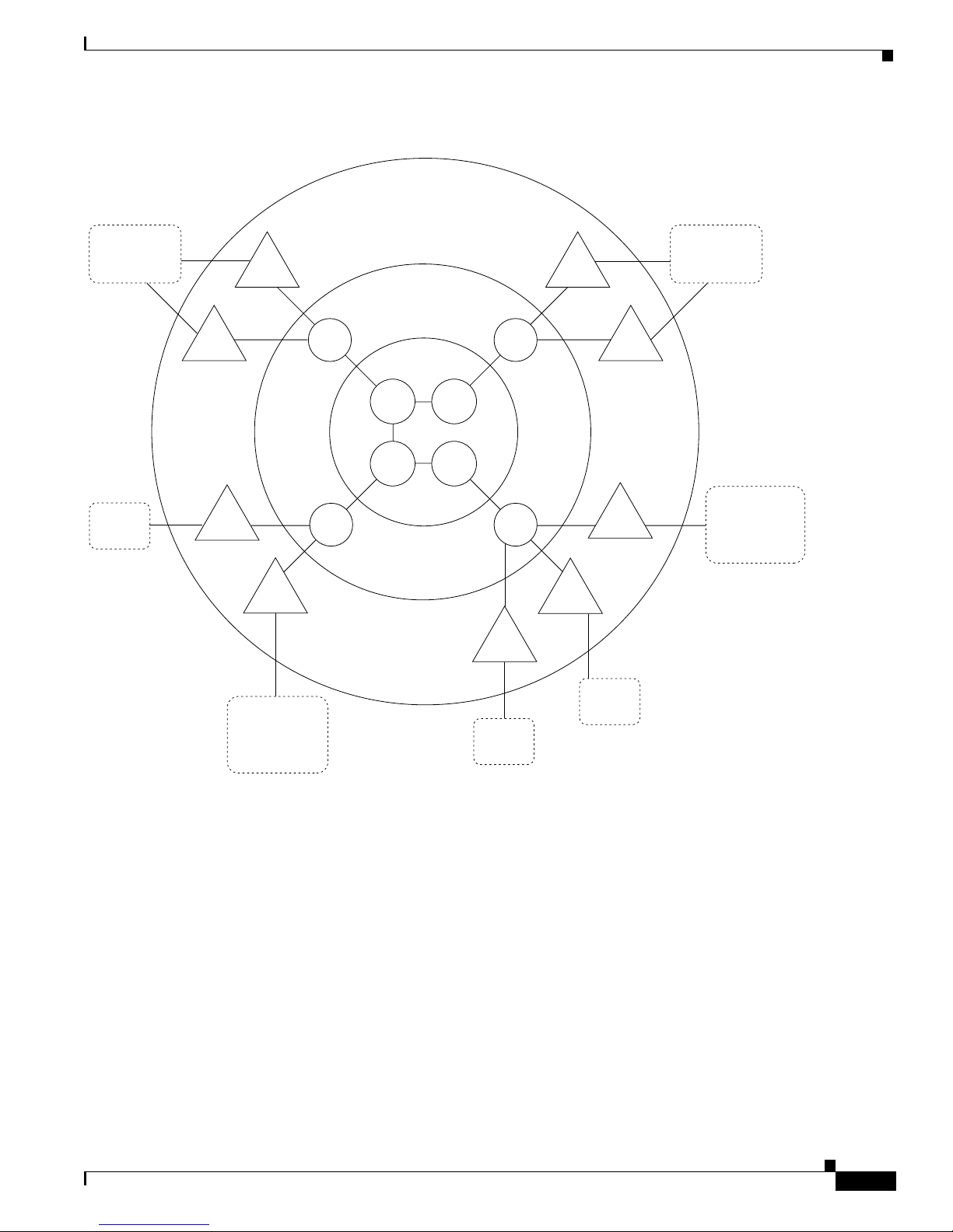
1-15
Cisco BPX 8600 Series Installation and Configurati on
Release 9.3.0, Part Number 78-10674-01 Rev. D0, July 2001
Chapter1 The BPX Switch : Functional Over view
BPX Switch Opera tion
Figure 1-6 Tiered Network with BPX Switch and IGX Switch Routing Hubs
BPX Routi ng Hubs in a Tiered Netw ork
Tiered networks with BPX routing hubs have the capability of adding interface shelves/feeders
(non-routing nodes) to an IGX/BPX routing network (Figure 1-7). Interface shelves allow the network
to support additional connections without adding additional routing nodes.
The MGX 8220 or MGX 8800 and IGX 8400 nodes configured as interface shelves are connected to
BPX routing h ub s .
The MGX 8220 and MGX 8800 support frame T1/E1, X.21 and HSSI Frame Relay, ATM T1/E1, and
CES, and are designed to support additional interfaces in the future.
ATM
Core Layer
Concentration
Layer
Access
(Feeder)
Layer
IGX
Hub
IGX
Hub
BPX
Hub
IGX
Shelf
Frame
Relay
Frame Relay
T1/E1 ATM
CES
FUNI
S6396
BPX
Hub
IGX
Shelf
IGX
Shelf
IGX
Shelf
IGX
Shelf
IGX
Shelf
Frame
Relay
Frame Relay
T1/E1 ATM
CES
FUNI
Voice, Data,
and
Frame Relay
Voice, Data,
and
Frame Relay
IGX
Shelf
Frame
Relay
MGX
8220
MGX
8220
IGX
switch
IGX
switch
BPX
switch
BPX
switch
Page 60

1-16
Cisco BPX 8600 Series Installation and Configuration
Release 9.3.0, Part Number 78-10674-01 Rev. D0, July 2001
Chapter 1 The BPX Switch: Functional Overview
BPX Switch Operatio n
Figure 1-7 Tiered Network with BPX Routing Hubs
Tiered Network Implemen tation
These requirements apply to BPX routing hubs and their associated interface shelves:
• MGX 8220 Release 4 level is required on all MGX 8220 interface shelves.
• Only one feeder trunk is supported between a routing hub and interface shelf.
• No direct trunking between interface shelves is supported.
• No routing trunk is supported between the routing network and interface shelves.
• The feeder trunks between BPX hubs and IGX interface shelves may be T3, E3, or OC-3 (since
Release 9 .2 .3 0).
• The f e eder trunks betwee n B PX hub s and MGX 822 0 or MGX 8 800 interface shelves ar e T 3, E3,
or OC-3-c/STM-1.
• Frame Relay an d ATM connection ma na ge men t t o an M G X 82 2 0 or M G X 8 8 00 in t er fa ce s helf is
provide by Cisco WAN Manager
• Telnet is supported to an interface shelf; the vt command is not.
• Remote printing by the interface shelf via a print command from the routing network is not
supported.
Routing network
IGX
shelf
IGX
shelf
IGX
shelf
IGX
shelf
IGX
shelf
IGX
shelf
MGX
8220
MGX
8220
MGX
8220
MGX
8220
IGX
IGX
CISCO WAN MANAGER
(network management)
Frame Relay
Frame Relay
Frame Relay
Frame Relay
Frame Relay
Frame Relay
Frame Relay
Frame Relay
Frame Relay
Frame Relay
CES
ATM T1/E1
ATM T1/E1
ATM T1/E1
CES
BPX
(routing
hub)
BPX
(routing
hub)
BPX
(routing
hub)
S5278xmod
Page 61

1-17
Cisco BPX 8600 Series Installation and Configurati on
Release 9.3.0, Part Number 78-10674-01 Rev. D0, July 2001
Chapter1 The BPX Switch : Functional Over view
BPX Switch Opera tion
Tier Network Definitions
Upgrades
Convert in g an I G X node to an inte rface shelf re qu ir es reconfiguri ng connect io ns on t he n od e because
no upgr a de path is provi ded in changing a routi ng node to an interface shelf.
A BPX node, acting as a Hub Node, is not restricted from providing any other feature normally
available on BPX nodes. A BPX Hub supports up to 16 interface shelves.
Connec ti ons with in tiered net wo r ks consist of d istinct segments within each tier. A r o uting seg m ent
traversesthe routing network, and a n interfaceshelfsegmentprovidesconnectivityto theinterfaceshelf
end-point . E ach of these segm en ts are a dd ed , c on f ig ured and delete d in dependen tl y of t he other
segments.
Annex G Annex G is a b i- directio nal protocol, d ef i ned in R ecommendation
Q.2931. It is used for monitoring the status of connectionsacross
a UNI interface. Tiered Networks use the Annex G protocol to
pass conne cti on status infor m ati o n bet w een a Hub Node and
attached int er f ace s he lf.
BPX Routing Hub A BPX node in the routing network which has attachedinterface
shelves. Also referred to as a hub node or BPX hub.
MGX 8220Interface Shelf A standards-based service interface shelf that connects to a BPX
routing hub, aggregrates and concentrates traffic, and performs
ATM ada pation f or transp ort ove r broadband ATM netwo r ks .
MGX 8800Interface Shelf A standards-based service interface shelf that connects to a BPX
routing hub, aggregrates and concentrates traffic, and performs
ATM ada pation f or transp ort ove r broadband ATM netwo r ks .
IGX Interf ac e Sh elf A special co nf ig u ra tio n o f an IGX switch that is connect ed as a
shelftoanIGXroutinghub.AnIGXinterfaceshelfissometimes
referred to as IGX A/F or feeder. The IGX interface shelfdoes not
perform routing functions nor keep track of network topology.
IGX Routing Hub An IGX node in the routing network which has attached IGX
interface shelves. Also referred to as a hub node or IGX hub.
Feeder Trunk Refers to a trunk that inte rc onn ect s an interface she lf w it h the
routing network via a BPX routing hub. A feeder trunk is
sometim es referred to as a n i nt erf ace shelf trunk.
IGX/AF Another name for the IGX interface shelf.
Routing Network The portion of the tiered network that performs automatic routing
between connection endpoints.
VPI Virtual Path Identifier.
VCI Virtua l C onnect ion Ide ntifier.
Page 62

1-18
Cisco BPX 8600 Series Installation and Configuration
Release 9.3.0, Part Number 78-10674-01 Rev. D0, July 2001
Chapter 1 The BPX Switch: Functional Overview
BPX Switch Operatio n
Use the Cisco WAN Manager Connection Manager to configure and c ontrol these individual segments
as a single end-to-end connection.
Interface shelves are attached to the routingnetwork via a BPX routing hub using a BXM trunk (T3/E3
or OC-3)or BNI trunk (T3/E3). The connection segments within the routingnetwork are terminated on
the BNI feed er trunks.
All Frame Relay connection types that can terminateon the BPX are supported on the BNI feeder trunk
(VBR , CBR, ABR, an d ATF types ). No check is made by t he routing networ k to valid a te whether the
connecti on s eg m e nt type being a dded to a BNI f eeder trun k is actually sup po r ted by the att ach ed
interface shelf.
Co-locating Routing Hubs and Interface Shelves
The trunk between an interface shelf and the routing network is a single point of failure, therefore, the
interface shelves should be co-located with their associated hub node. Card level redundancy is
supported by t he Y- C ab le re du ndan cy for the BXM, B N I, AIT, an d BTM.
Networ k Manageme nt
Commun ic ation betw een CPE devices and the rou ti ng network is p rov id ed in accordan ce w i th A n nex
G of RecommendationQ.2931. This is a bidirectional protocol for monitoring the statusof connections
across a UNI interface. (Note: the feeder trunk uses the STI cell format to provide the ForeSight rate
controlled congestion management feature.)
Communication includes the real time notification of the a ddition or deletion of a connection segment
and t he ab ili ty to pas s the ava ilabili ty (active state) or unavailability (inactive state) of t h e conn ections
crossing this interface.
A proprietary extension to the Annex G protocol is implemented which supports the exchangeof node
information between an interface shelf and the routing network. This informationis used to supportthe
IP Relay feature and the Robust Update feature used by network management.
Network Management access to the interface shelves is throughthe IP Relay mechanism supported by
the SNMP a nd TFTP proje ct s or b y d ir ect attachm en t to th e i nt er face shelf. The IP Re lay mechanism
relays tr affic from the routing netwo r k to the attached i nt e rfa c e s he lv es . No IP R elay support is
provided from the interface shelves into the routing network.
The BPX routing hub is the source of the network clock for its associated feeder nodes. Feeders
synchroniz e t heir tim e and date to match their routing hub.
Robust Object and Alarm Updates are sent to a network manager that has subscribed to the Robust
Updates feature. Object Updates are generated whenever an interface shelf is added or removed from
the hub node and when the interface shelf name or IP Address is modified on the interface shelf. Alarm
Updates a re generated whenever the alarm state of the interface shelf changes between Unreachable,
Major, Minor an d OK alarm st ate s .
An interface shelf is displayed as a unique icon in the Cisco WAN Manager topology displays. The
colors of the icon and con necting trunks ind icate the a lar m state of each.
Channelstatistics are supported by FRP, FRM, ASI, and MGX 8220 endpoints.BNIs, AITs, and BTMs
do not suppo rt chann el stati sti cs . Trunk St ati sti cs are s u p po r ted for the f ee de r trunk and are id en ti cal to
the exi s ti ng BNI trun k statistics.
• Preferred Routing
Preferred routing within the routing network can be used on all connections. Priority bumping is
supported within the routingnetwork,but not in the interfaceshelves. All otherconnectionfeatures
such as conditioning, rrtcon, upcon, dncon, and so on, are a lso supported.
Page 63

1-19
Cisco BPX 8600 Series Installation and Configurati on
Release 9.3.0, Part Number 78-10674-01 Rev. D0, July 2001
Chapter1 The BPX Switch : Functional Over view
BPX Switch Opera tion
• Local and Remote Loopb acks
Connection local and remote loopbacks are managed at the user interface of the FRP endpoint
routing node or interface shelf. Remote loopbacks are not supported for DAX connections. The
command addlocrmtlp supports remote loopbacks at FRP DAX endpoints.
• Testcon and Testdly
Tstcon is supported at the FRP endpoints i n a non-integrated fashion and is limited to a pass/fail
loopback test.Fault isolation is not performed. Thisis the same limitationimposedon inter-domain
connections. Intermediate endpoints at the AIT and BNI cards do not support the tstcon feature.
Tstdelay is also supported for the FRP and ASI in a non-integrated fashion similar to that of the
tstcon command.
Inverse Multiplexing ATM
Where greater bandwidths are not needed, the Inverse Multiplexing ATM(IMA) featureprovidesa low
cost trunk between two BPX switches.
The IMA feature allowsBPX switchesto be connectedto one anotherover any of the 8 T1 or E1 trunks
provided by an IMATM module on an MGX 8220 shelf. A BNI or BXM port on each BPX switch is
directlyconnectedtoanIMATMmoduleinanMGX8220byaT3orE3trunk.TheIMATMmodules
arethenlinkedtogetherbyanyofthe8T1orE1trunks.
Refer to th e Cisco MGX 8220 Reference and the Cisco WAN Swi tch ing Com m and Reference
publicat io ns for f ur th er i nf o rmation.
Virtual T runking
Virtual trunking provides the ability to define m ultiple trunks within a single physical trunk port
interface. Virtual trunk ing ben ef it s in clude th e followin g :
• Reducedcostby configuring the virtualtrunkssupplied by the publiccarrierforas m uch bandwidth
as needed instead of at full T3, E3, or OC-3 bandwidths.
• Utilization o f th e full mesh c apability of the pub lic carrier to reduce t he number of leased line s
neededbetweennodesintheCiscoWANswitchingnetworks.
• Choice of keeping existing leased lines between nodes, but using virtual trunks for backup.
• AbilitytoconnectBNIorBXMtrunkinterfacestoapublicnetworkusingstandardATMUNIcell
form a t.
• Virtualtrunkingcanbe provisioned via either a Public ATM Cloudor a Cisco WAN switchingATM
cloud.
A virtu a l trunk may be de fined a s a “trunk ov er a public ATM servi ce. ” The trunk really doesn’texist
as a physical line in the network. Rather, an additional level of reference, called a virtual trunk
number, is use d to diffe re ntiate the virtu al trunks f o und wit hi n a physical tr unk port.
Figure 1-8 shows four Cisco WAN switching networks, each connected to a Public ATM Network via
a physicalline. The PublicATM Network is shown linking all four of these subnetworks to every other
one w ith a full meshed n etw o r k of virtual trunks. I n this exa mple, e ach ph y s ical li ne is config ur ed w it h
three vir tual tru n ks .
Page 64

1-20
Cisco BPX 8600 Series Installation and Configuration
Release 9.3.0, Part Number 78-10674-01 Rev. D0, July 2001
Chapter 1 The BPX Switch: Functional Overview
Traffic and Congestion Management
Figure 1-8 Virtual Trunking Example
Traffic a nd Congestion Management
The BPX switch provides ATM standard traffic and congestion management per ATM Forum TM 4.0
usin g BXM cards.
The Traffic Control functions include:
• Usage Parameter Control (UPC)
• Traffic Shaping
• Con nection Management Control
• Select ive Cell Discardin g
• Expl icit Forw ar d Congestio n Indicat io n (E F CI)
• Priority Bumping
In addition to these standard functions, the BPX switch provides advanced traffic and congestion
management features including:
• Support for the full range of ATM service types per ATM Forum TM 4.0 by the BXM-T3/E3,
BXM-155, a nd BXM-622 cards on the BPX Service Node.
• Advanced CoS Management (formerly Fairshare and Opticlass features) C lass of Service
management delivers the required QoS to all applications.
–
The BPX provides per virtual circuit (VC) queuing and per-VC-scheduling provided by rate
controlled servers and m u lt ip le class-of-ser vi ce queuing at n etw o r k in gr ess .
–
On egre s s , up t o 16 queues with independent serv ice algor ithms fo r each trunk i n the n e twork.
• Automatic Routing Management (formerly AutoRoute feature), end-to-end connection
management that automatically selects the optimum connection path based upon the state of the
network and assures fast automatic alternate routing in the event of intermediate trunk or node
failures.
• Cost-B as ed R o ut in g Managemen t
Cisco
sub-network
Cisco
sub-network
Cisco
sub-network
Cisco
sub-network
Public ATM
Network
ATM-UNI ATM-UNI
ATM-UNI ATM-UNI
Virtual trunk
Leased line
H8227
Leased line
(backup)
Page 65

1-21
Cisco BPX 8600 Series Installation and Configurati on
Release 9.3.0, Part Number 78-10674-01 Rev. D0, July 2001
Chapter1 The BPX Switch : Functional Over view
Traffic and Congesti on Managem ent
• ABR Standard with VSVD
Congestion control using RM cells and supported by BXM cards on the BPX Switch.
• Optimized B andwidth M anagement (formerly ForeSight)
An end-to-end closed loop rate based congestion control algorithm that dynamically adjusts the
servic e rate of VC queue s based o n network conges tion feedbac k.
• Dynamic Buffer Management
Cisco’s Frame Relay and ATM service modules are equipped with large buffers and a dynamic
buffer m anagement t e c h nique for allocati ng and sca ling the buffers o n a p er VC basis to traffic
entering or leaving a node. The switch dynamically assigns buffers to individual virtual circuits
based on the amount of traffic present and service level agreements. The large queues readily
accomm odate larg e b ursts of traffic into the nod e.
• PNNI
A standar d s-b ased routin g protocol for ATM and F ra me R el ay SVCs.
• Early and par tial pa cket dis c ard for A AL5 c onnect ions.
Advanced CoS Management
AdvancedClass of Service (CoS) managementprovides per-VC queueingand per-VCscheduling. CoS
management provides fairness between connections and firewalls between connections. Firewalls
prevent a single non-compliant connection from affecting the QoS of compliant connections. The
non-compliant connection simply overflows its own buffer.
The cells received by a port are not automatically transmitted by that port out to the network trunks at
the p o rt access r ate. Ea ch VC is assig n ed its ow n ingr ess qu eu e that buff er s the conn ec tio n at the entr y
to the ne tw ork. With A BR with VSVD or with Optimi zed Band w idth Man agement (ForeSi gh t) , the
service rate can be adjusted up and down depending on network congestion.
Network queues buffer the data at the trunk interfaces throughout the network according to the
connecti on ’s class of service. Service classes are defined by standards-based QoS. Classes can consist
of the five service classes defined in the ATM st an da rd s as wel l as m ul ti pl e s u b -c la ss es to eac h of th ese
classes. Classes can rang e fr om co n s ta nt bit rate ser v ice s wi th m in imal cell del ay var ia tion to variabl e
bit r ates with l ess st ri ng en t cel l del ay.
When cells are received fromthe network for transmission out a port,egress queues at thatport provide
addition al b uffer in g based on the se rv ic e c lass of t he connection .
CoS Manag ement provid es an eff ect iv e m ean s o f man ag i ng th e quality of serv ic e d efin ed for v ar iou s
types of traffic. It permits n etwork operators to segregate traffic to provide more c ontrol over the way
that network capacity is dividedamong users. This is especiallyimportantwhen there are multiple user
services on one network. The BPX switch provides separate queues for each traffic class.
Rather than limiting the use r to the five broad classe s of service de fined by the ATM standa r ds
committe es , CoS manage m en t can provide up to 1 6 classes of service (ser vice sub classes) t h at you can
further define a nd assign to connections. Some of the COS parameters that may be assigned include:
• Minimumbandwidth guarantee per subclass to assure that one type of traffic will not be preempted
by another.
• Maximum bandwidth ceiling to limit the percentage of the total network bandwidth that any one
class can ut il ize.
• Queue depths to lim i t t he delay.
• Discard threshold per subclass.
Page 66

1-22
Cisco BPX 8600 Series Installation and Configuration
Release 9.3.0, Part Number 78-10674-01 Rev. D0, July 2001
Chapter 1 The BPX Switch: Functional Overview
Traffic and Congestion Management
These cla ss of ser v ic e p ar ameters are based on the stan da rd s- b as ed Q u ali ty of Se rv ic e p aram e ter s an d
are softwar e programmab le by t he user.
Automatic Routing Managem ent
With Automatic Routing Management (formerly referred to as AutoRoute),connections in Cisco WAN
switching networks are added if there is sufficient band w id th ac ro ss the netw or k and are autom atically
routed when they are added.
You need enter only the endpoints of the c onnection at one end of the connection and the IGX switch,
and BPX s w i tch soft w ar e aut om ati cally set up a route ba sed on a sophist icated routin g algo ri th m. Thi s
feature is call ed Automatic Routing M an agement. It is a standard feature on t he IG X and BPX switc hes.
System software autom at ica ll y sets u p the mos t direct r o ut e after co nsi d er in g the netw o r k topology and
status, the amount of spare bandwidth on each trunk, as well as any routing restrictions entered by the
user (for example, avoid satellite links). This avoids having to manually enter a routing table at each
node in the network. Automatic Routing Management simplifies adding connections, speeds rerouting
around network failures, and provides higher connection reliability.
Cost-Based Rout ing Management
You can selectively enable cost-based route selection as the route selection per node. With this feature
a tr un k cost is assig n ed to each tr un k (ph y sical and virtual) in the net wor k . The rou ti n g algo ri th m the n
choose s the lowest cost route to the des t inati on node. The lowe s t cost routes ar e stored in a cache to
reduce the com putati on time for on-demand routing.
Cost-based routin g can be enabled o r di s ab le d a t a nytime. Ther e c an be a mixture of co st- b as e d a nd
hop-based nodes in a network.
The section, Cost-Based Connection Routing, contains more detailed information about cost-based
AutoRoute.
Priority Bumping
Priority bumping allows BPX and IGX switch c onnections classified as more important (via COS
value) to “bum p” (that is, set aside) existing connections of lesser importance. While the AutoRoute
feature i s capabl e of au to matical ly redirecting all fai led conne ct io ns onto other paths, priorit y bumpin g
lets you prioritize and sustain more important connections when network resources are diminshed to a
pointthat all connections cannotbe sustained. Network resourcesare reclaimedfor the moreimportant
connections by bumping (derouting) the traffic on less important connections.
Priority bumping is triggered by insufficient resources (such as bandwidth), resulting fromany number
events,includingchangesto the network made by usingthe commands addcon, upcon, cnfcon,cnnfcos,
cnfpref, c nftrk, deltrk. Other t riggers include trunk line/card failure, node failure, a nd comm. failure.
The m os t promi ne nt event is a trunk f ai lure.
For informationon setting up Priority Bumping, see “SpecifyingPriority Bumping” in Chapter 10 of
the Cisco WAN Switching Command Reference.
Page 67

1-23
Cisco BPX 8600 Series Installation and Configurati on
Release 9.3.0, Part Number 78-10674-01 Rev. D0, July 2001
Chapter1 The BPX Switch : Functional Over view
Traffic and Congesti on Managem ent
ABR Standard with VSVD Congestion Control
TheBPX/IGXswitchnetworksprovidea choice of two dynamicrate based congestion control methods,
ABR wit h VSV D and Op t imi zed Ban dwi dt h Management (ForeSig h t) . This section describes Standar d
ABR with VSVD.
Note ABR with VSVD is an optional feature that must be purchased and enabled on a single
node for the entire network.
When an ATM connection is configured between BXM cards for Standard ABR with VSVD per ATM
Forum TM 4.0, Resource Management (RM) cells are used to carry congestion control feedback
informationbacktotheconnection’s s ource fr om the connection’s destin ation.
The ABR sour ces periodically inter leave RM cell s in to the d at a th ey a re tr an sm i tt in g. T hese RM cell s
are called forward RM cells because they travel in the same direction as the data. At the destination
these cells are t ur n ed around and sen t b ack t o the so u rc e a s b ack w ar d RM c ell s .
The RM cells c on t ain field s to increa s e o r decrease the r at e (the CI and NI field s) or se t i t at a pa rt ic ul ar
value (t he explic it r a te E R f ield). Th e interven in g switch es may adju st these fields accor d in g to netwo r k
conditions. When the source receives an RM cell, it must adjust its rate in response to the setting of
these fields.
When spare capacity exists with the network, ABR with VSVD permits the extra bandwidth to be
allocated to ac ti ve virtual circu its.
Optimiz ed B andwidth Managem ent ( ForeSight) Congestion C ont rol
TheBPX/IGXswitchnetworksprovidea choice of two dynamicrate based congestion control methods,
ABR with VSVD and Cisco’s Op ti m iz ed Bandwidth M a nagement ( Fo re S ig ht ) . Th is section descr ib es
Optimized Bandwidth Management (ForeSight).
Note Optimized Bandwidth Management (ForeSight) is an optional feature that must be
purchased a nd e nabled on a single node for the entire network.
Optimized Bandwidth Management (ForeSight) m ay be used for congestion control across BPX/IGX
switches for connections that have one or both end points terminating on cards other than BXM. The
ForeSight feature is a dynamic closed-loop, rate-based, congestion management feature that yields
bandwidth savings compared to non-ForeSight equipped trunks when transmitting bursty data across
cell-based networks.
ForeSight pe rmits users to burst a bove their committe d inform a ti on rate fo r extended periods of time
when the r e is unused net work bandwidth a vailable. This enables use r s to m aximize the u s e of n etwork
bandwidth while offering superior congestion avoidance by actively monitoring the state of shared
trunks carrying Frame Relay traffic within the network.
ForeSigh t mo n ito r s each pat h in the forw ar d dir ect io n to detect a ny po in t wher e congestion ma y oc cu r
and returns the information back to the entry to the network. When spare capacity exists with the
netwo rk , ForeSi gh t p er m its the ex tr a bandwid th to b e alloc ate d t o active virt ual circu its . Each PVC i s
treated f ai rl y by allocatin g th e extra band wi d th based on eac h PVC's comm it ted band w id th parame ter.
Page 68

1-24
Cisco BPX 8600 Series Installation and Configuration
Release 9.3.0, Part Number 78-10674-01 Rev. D0, July 2001
Chapter 1 The BPX Switch: Functional Overview
Network Ma nagement
If the netwo r k reaches full u til ization, ForeSight detects thi s an d quickly acts to redu ce the extra
bandw idth allocat e d to the active PVCs. Fore S ight reacts q uickly to net work loading in or der to pr event
dropped pac ke ts. Per io di cal ly, each n o de auto m a tically meas ures th e delay experience d alon g a Frame
Relay PV C . This delay facto r is used in cal cu lating th e ForeSight algorithm .
With basic Frame Relay service, only a single rate parameter can be specified for each PVC. With
ForeSight, the virtual circuit rate can be specified based on a minimum, maximum, and initial
transmi s sion rate fo r m o re flexibilit y in d ef in in g the F r ame Relay circuits .
ForeSight provides effective congestion management for PVC's traversing broadband ATM as well.
ForeSight operates at the cell-relay level that lies below the Frame Relay services provided by the IGX
switch . With t he queue size s u tilized in the BPX switch, th e b andwid th savings is approximately the
same as ex perienced wit h lower speed t run ks. When the cost of these line s is c on s i de re d, th e savings
offered by Fo reSight can be signific ant.
Network Management
BPX switches prov id e o ne high-sp eed and two lo w- sp eed data interfa ces for data coll ect io n and
network managemen t:
• High- sp eed interface
An Ethernet 802.3 LAN interface port is provided for communicating with a Cisco WAN Manager
NMS workstation. TCP/IP provides the transport and network layer, Logical Link Control 1 is the
protocolacross the Ethernet port.
• Low- sp eed interfaces
Two RS-232 ports ar e provided: one for a netw ork printer and the sec ond for either a modem
connecti on o r a c o n ne cti on to an exter n al co n tr ol t er min al . These low -sp ee d in terfaces are the sam e
as p r ov id ed by the IGX sw i tch .
Each B P X swit ch can be config u re d to use optiona l low- spe ed mo de ms for inwa rd access by the Cis co
Techni cal Response Team for net wor k troubleshoot in g as si s tan ce or to autodial Cust omer Serv ice to
report alarms remotely. If desired, another option is remote monitoring or control of customer premise
equipment through a window on the Cisco WAN Manager workstation.
A Cisco WAN M an ag er N MS works ta tio n connects vi a t he Ethernet to t he L A N p or t on the BPX and
provides n etw o r k m an ag em e nt v ia SNMP. Statistics are co ll ected by Ci sco WAN Manager using the
TFTP protocol.
You can also use the Cisco WAN Manager’s Connect io n Manager to ma na ge:
• Frame Relay connections on IGX switch shelves
• Frame Relay and ATM connections on MGX 8220 shelves
• MGX 8220 shelf configuration.
Network Management software includes these applications:
• Cisc o WAN Manager (f ormer ly StrataView P l us)
A single unified management platform utilizing HP OpenView® to manage BPX, IGX, a nd SES
device s.
• StrataSphere BILLder
Monitors tr affic flow over a netw o rk an d captures d ata per standa rd or cu sto m i zed billing per i od s
and format s.
Page 69

1-25
Cisco BPX 8600 Series Installation and Configurati on
Release 9.3.0, Part Number 78-10674-01 Rev. D0, July 2001
Chapter1 The BPX Switch : Functional Over view
Network Management
• StrataSphere Modeler
Network modeling tool used for preliminary design of new networks and for analysis and
modificat ion stud ies of e xi s tin g n etw orks.
• StrataSphere Adaptor
Exports network modeling information to external third party modeling systems.
• SNMP Service Agent
A service ag en t th at pr ovi de s an i nt er face for au to mat ed provisionin g an d fa ul t m an agem e nt to
customers or Operations Support Systems (OSS).
For further information on network management, refer to the Cisco WAN Manager Operations
publication.
Cisco WAN Mana ger
Cisco WAN Manager is a single unified management platform utilizing HP OpenView® to manage
BPX, IGX, and SES devices. It provides a standards-based m ultiprotocol management architecture.
Regardless of the size or configuration of your network, Cisco WANManagercollectsextensiveservice
statistics, tracks resource performance, and provides powerful remotediagnostic and controlfunctions
for WAN maintenance.
Online hel p scr een s, graphica l displays, and easy comman d line mnem on ics make Cis co WAN M an ag er
user-friend ly. Plenti f ul h ar d disk stora ge is pr ov i de d t o all o w accumulati ng t im e of day statistics on
many network parameters simultaneously. The data is accumulated by the node's controller card and
transm itted t o the Cisco WAN Manager workst ation where it is s tore d, processed, an d display e d on a
large color monitor.
Cisco WAN Manager connects to the network over a n Ethernet LAN connection. With Ethernet, you
can establi s h Ci s co WAN Manager connectivi ty to remote nod es via f r ame relay over TCP/IP to the
LAN connector on the local node, or via inband ILMI.
Cisco WAN Manager pr ovide s i n-band management of netw ork ele m ents vi a S NMP agent inter faces
and MIBs embedded in each node and Interface Shelf. The SNMP agent allows a user to manage a
StrataCom n etw o r k or s u b-n et wo r k fr o m a ny S N M P- based inte grat ed network man ag em en t s ys tem
(INMS).
• Con nection Mana gement
The Cisco WA N M an ag er Connection Manager enab le s y ou to perform co nnection pro v isio n in g
suchas adding,configuring,and deletingframe relay,ATM,and frame relay-to-ATM interworking
connecti on s.
• Network Topology
A map o f the ne tw ork is gener ated at sy s tem ins tallat ion to g raphic a lly display a ll nodes, trunks ,
circuit lines, and access devices in the network. Various colors are used to indicate the status of
each netwo rk i tem. You can zoom in to displ ay s pe ci fi c net wo r k de tai ls w h il e a sm a ll ov er v iew map
remains di spl ay ed as a loc ato r.
• Netwo r k P erfo r man ce
Statistics ar e collected an d temporarily s t or ed b y each node in th e n et w or k an d released to Cis c o
WAN Manager when you enable polling, and in accordance with your c onfiguration for specific
informat io n with in repo rts . Cisco WAN M an ag er then stores stati s tic s in a rela ti on al datab a se; you
retrieve and view these statistics by invoking a statistics display window from the Cisco WAN
Manager GUI. From data gathered throughout the network, you can quickly view the operational
integrity an d d e p lo yment o f insta ll ed netw o rk devices and commu nication media by a c ti vating and
invoking sta tistics di s p lays.
Page 70

1-26
Cisco BPX 8600 Series Installation and Configuration
Release 9.3.0, Part Number 78-10674-01 Rev. D0, July 2001
Chapter 1 The BPX Switch: Functional Overview
Network Ma nagement
• Equipm en t Manag ement
The Cisco WAN Man ag er Eq u ip men t Manager provi d es t he ab il ity t o perform equip men t
management functions such as adding lines and ports on a Cisco MGX 8220 edge concentrator
shelf.
• Alarm Reporting/Event Log
Cisco WAN M a n ag er displ ays major an d min or alar m status on its topol og y scre en for all nodes in
a network.It also providesan event log with configurable filteringof the log events by node name,
start time, en d time, alarm ty pe , a nd u ser s p eci f ied se ar ch string.
• Software Updates
System software and software updates are supplied on magnetic tape or floppy disk. You can then
load the system software files onto the Cisco WAN Manager workstation where they can be
downloaded to a buffer memory in each node in the network in a background mode without
disturbing network operation.When the loading is completefor all nodes,you issue a command to
switch all no de s ov er to the new software. The prev i ou s sof t wa re is p re ser ved and can be recal led
at any tim e.
• Back up
You can obtain a ll net w or k conf iguratio n files from the net wo r k and store th em on the Cisco WAN
Manager workstation for backup purposes. In the event of a system update or a node failure, you
can download the configuration files to one or all nodes for immediate system restoration.
Network Interfaces
Networkinterfaces c onnectthe BPX switch to other BPX or IGX switchesto form a wide-areanetwork.
The BPX switch provides these trunk interfaces:
• T3
• E3
• OC-3/STM-1
• OC-12/STM-4
The T3 physi cal interfa ce utilizes DS3 C-bit parity an d th e 53-byte ATM ph ysi ca l l ay er cell relay
transmission usi ng the Ph ys ical Layer Converg e nce Pro tocol.
The E3 physi ca l i nter fa ce uses G.804 for cell del in eat io n and HDB3 line co d in g.
The BXM-622 cards support these physical interfaces:
• SMF
• SMFLR
The BPX switch supports network interfaces up to 622 Mbps and provides the architecture to support
higher broa db an d n etw o rk i nter f ace s as the n eed arises.
Optio nal redundan cy i s on a on e-to-one basis. The p hysical inter face can o perate e ither in a nor mal or
looped clock mode. As an option, the node synchronization can be obtained from the DS3 extracted
clock for an y selected ne two rk trunk.
Page 71

1-27
Cisco BPX 8600 Series Installation and Configurati on
Release 9.3.0, Part Number 78-10674-01 Rev. D0, July 2001
Chapter1 The BPX Switch : Functional Over view
Network Management
Service Int erfaces
Service interfaces connect ATM customer equipment to the BPX switch. ATM User-to-Network
Interfaces (UNI) and ATM Netw ork -t o -Net w ork Interfaces (NN I ) te rm in ate on t he ATM Se rvi ce
Interface (ASI) cards and on BXM T3/E3, OC-3, and OC-12 cards configured for a s service interfaces
(UNI access mode).
The BXM T3/E3 card supports the standard T3/E3 interfaces.
The BXM-155 cards support SMF, SMFLR, and MMF physical interfaces.
The BXM-62 2 cards support SM F an d S MF LR ph y sic al i nter f ace s.
The BXM cards supportcell relay connectionsthatare compliantwith boththe physicallayer and ATM
layer standards.
The MGX 8220 interfaces to a BNI or BXM card on the BPX, via a T3, E3, or OC-3 interface. The
MGX 8220 provides a concentrator for T 1 or E1 Frame Relay and ATM connectionsto the BPX switch
with the ability to apply Optimized Bandwidth Management (ForeSight) across a connection from
end-to-end. The MGX 8220 also supports CES and FUNI (Frame Based UNI over ATM) connections.
Statistical Alarms and Network Statistics
TheBPX Switchsystemmanagercan configure alarm thresholdsfor all statistical type errorconditions.
Thresholds are configurable for conditions such as frame errors, out of frame, bipolar errors, dropped
cells, and c el l head er errors. Wh e n an alarm thres h ol d is e xc eed ed , t he N M S scr een displays an alarm
message.
Graphical displays of collected statistics information, a feature of the Cisco WAN Manager NMS, are
a useful tool for monitoring network usage. Statistics collected on network operation fall into four
general categories:
• Node s tat istics
• Network trunk statistics
• Network Ser vi ce, line statis t ics
• Netwo r k S er vi ce, port statisti cs
These sta ti s tic s a r e col le c ted in real-time t hr o ug hout the netw o r k an d fo rw arded to the WAN Ma nager
workstation for logging and display. The link from the node to the Cisco WAN Manager workstation
uses a proto col to acknow l ed ge receipt of each statistics da ta packet.
Refer to th e Cisco WAN Manager Operations publication, fo r more deta il s o n s tat istics and s tat is t ica l
alarms.
Node Synchronization
A BPX Service switch network provides network-wide, intelligent clock synchronization. It uses a
fault-tolerant network synchron iz a ti on archi tecture r ecommended for Integrated Services D igital
Network (ISDN). The BPX switch internal clock operates as a Stratum 3 clock per ANSI T1.101.
Because the BPX switch is designed to be part of a larger communications network, it is capable of
synchroniz ing to higher-l e vel network clocks a s well as p r ovidi ng synchroniza tion to l ower-le vel
devices. You can configure any n etw o rk access input to syn ch r onize the node. Any ex ternal T1 or E1
input can also be configured to synchronize network timing.
Page 72

1-28
Cisco BPX 8600 Series Installation and Configuration
Release 9.3.0, Part Number 78-10674-01 Rev. D0, July 2001
Chapter 1 The BPX Switch: Functional Overview
Switch Soft w are Desc r ip tio n
A clock outputallowssynchronizing an adjacentIGX switchor othernetworkdeviceto the BPX switch
and the network. In nodes equipped with optional redundancy, the standby hardware is locked to the
active har d w ar e t o m in imize sys tem disruption d uring sys te m s w i tch o vers.
You can configure the BPX Service Node to select clock from these sources:
• External (T 1/E1 )
• Line (DS3/E 3)
• Internal
Switch Software Description
The C isco WAN switching cell relay system software shares most core system s oftware, as well as a
library o f app l ica tio n s, b et w een p lat f orm s. System software prov id es bas i c ma na ge m en t and c ontr o l
capabilit ies to each node.
BPX node system software manages its own configuration, fault-isolation, failure recovery, and other
resources. Because no remote resources are involved, this ensures rapid response to local problems.
This distributed network control, rather than centralized control, provides increased reliability.
Software among multiple nodes cooperates to perform network-wide functions such as trunk and
connection m anagem ent. Th is multip rocess or appr oach en s ur e s rapid respon s e w ith no sin gle point of
failure. S yst em software ap p lications pr ov i de advanced features th at yo u c a n in s tal l a nd c on f ig ur e as
required.
Some of th e m an y s oftw are features are:
• Autom atic routin g of connect io ns (Automatic Routing Man ag ement fea tu re ).
• Various classes of service that may be assigned to each connection type (Advanced CoS
Management).
• Bandwidth reservation on a time-of-day basis.
• Detection a nd control of network congestion with ABR with VSVD or Optimized Bandwidth
Management (ForeSight) algorithms.
• Automatic self-testing of each component of the node.
• Automatic c ol lecting an d reportin g of many network-wide statis tics, su ch as trunk loading,
connecti on u sag e, and t r unk error r at es , as y ou s p ec if y.
The sy stem s oftw a re , config u ra ti on databas e , and the firmwar e that controls the opera t ion of each card
type is resident in programmablememory and can be stored off-line in the Cisco WAN Manager NMS
for immed iate back up i f necessary. T h is so f tw ar e and f i rm wa re is easily upd at ed r e mo tely from a
central si te or fr om Customer Ser vi ce, which reduc es t he li ke li ho od o f early obso lescence.
Connecti ons and Connec t i on Ro ut i ng
The routing software supports the establishment, removal and rerouting of end-to-end channel
connection s . There are three routing m odes:
• Automatic Routing
The sys tem software computes the best route for a connection.
• Manual Routing
You can specify the route for a c onnection.
Page 73

1-29
Cisco BPX 8600 Series Installation and Configurati on
Release 9.3.0, Part Number 78-10674-01 Rev. D0, July 2001
Chapter1 The BPX Switch : Functional Over view
Switch Softwa re Des cription
• Alternate Routing
The system sof tw ar e automatically rer o ut es a failed connecti on .
The system software uses these criteria when it establishes an automatic route for a connection:
• Select s th e m ost direct rout e betw een two n odes .
• Selects unloaded lines that can handle the increased traffic of additional connections.
• Takes into consideration user-configured connection restrictions (for example whether or not the
connec ti on is restricted to terrest ri al lines or can include satellite hops or ro u tes configured for
route diversity).
When a node reroutes a connection, it uses these criteria and also looks at the priority that has been
assigned and any user-configuredroutingrestrictions.The node analyzestrunk loadingto determinethe
number o f cells or packets the network can succe s s fully deliv er. Within these loading limit s , th e node
can calculate the maximum combination allowed on a network trunk of each type of connection:
synchrono us data, ATM traffic, F r ame Relay data, m ul ti med ia data, voice, an d compressed v oi ce.
Network-wide T3, E 3, OC-3, or OC-12 c onnections are supported between BPX switches terminating
ATM user devices on the BPX switch UNI ports. These connections are routed using the virtual path
and/or virt ua l c ir cu it ad dr ess i n g fi eld s i n th e ATM cel l header.
Narrowband connections can be routed over high-speed ATM backbone networks built on BPX
broadband swit ches. FastPacket addresses are translat ed into ATM cell addresses that are then u sed to
routethe connectionsbetweenBPX switches,and to ATM networks with mixed vendor ATMswitches.
Routing algorithms select broadband links only, avoiding narrowband nodes that could create a choke
point .
Connecti on Routing Groups
The re-routing mechanism ensuresthat connections are presortedin order of cellloading when they are
added. Each routing group contains connections with loading in a particular range. The group
containing the connections with the largest cell loadings is rerouted first, and subsequent groups are
then rerouted on down to the last group t hat contains connections with the smallest cell loadings.
There are three configurable parameters for configuring the rerouting groups:
• Total number of rerouting groups
• Starting load size of first group
• Load size range of each group
You configure the three routing group parameters by using the cnfcmp ar m command.
For example, there might be 10 groups, with the starting load size of the first group at 50, and the
increme nt al lo ad size of each s u cce ed ing group b ein g 10 cells. The n gr o up 0 would cont ain all
connecti on s requiring 0 –59 cell load units,group 1 would c ontainall connections requiring from 60–69
cell load units, on up through group 9 which would contain a ll connections requiring 140 or more cell
load units .
Table 1-1 Routing Group Configuration Example
Routing group Con nectio n cell loadin g
00–59
160–69
270–79
Page 74

1-30
Cisco BPX 8600 Series Installation and Configuration
Release 9.3.0, Part Number 78-10674-01 Rev. D0, July 2001
Chapter 1 The BPX Switch: Functional Overview
Switch Soft w are Desc r ip tio n
Cost-Base d Con nection Routing
In standard AutoRoute, thepath with the fewest numberof hops to the destinationnode is chosen as the
best ro ute. Cos t - based r oute se le ction u s e s an adm inistrative trunk co s t routing m etric . The path with
the lowest total tru nk cost is c hosen a s the be s t r o ute.
Cost-based r oute selection is based on D ijkstra’s Shortest Path Algorithm, which is w id ely used in
network routing environments. You can use cost-based route selection (that is, cost-based AutoRoute)
togive preference toslower privatelyowned trunksover faster public trunksthat charge based on usage
time. This gives network operators more control over the usability of their network trunks, while
provi ding a more st andard algor ithm for route selection.
Major Features of Cost-B as ed AutoRout e
Here is a sho r t descriptio n of t he major functi on al el em e nt s o f Co s t-Based Route Selection .
• Enabling Cost-Based Route Selection.
You enable cost-based route selection at any time. This feature does not require special password
access. Th e def au lt algorithm is t he hop-based al go r ith m .
• Configuring Trunk Cost
You assign a trunk cost t o each trunk (physical and v irtual) in the network. One cost i s assi gned per
trunk;no separate costs are used for different connectionor service types.The valid range of trunk
costs is 1 (lowest cost) to 50 (highest cost). A trunk has a default cost of 10 upon activation. T he
cost of a trunk can be changed before or after the trunk has been added to the network topology.
The cost can also be change d af ter c on n ect io ns ha ve b een r o ut ed o ve r th e tr unk. Such a chan ge d oes
not initiate automatic connection rerouting,nor does it cause any outage to the routed connections.
If t he new trunk cos t ca us es t he allowable ro ute c ost for a ny connect io ns to b e exce ed ed , t he
connections must be manually rerouted to avoid the trunk. This avoids large-scale simultaneous
network-wide rerouting and gives you control over the connection reroute outage.
• Cache vs. On-Demand Routing
In previous releases, Hop-Based Route Selection always requires on-demand routing. On-demand
routing initiates an end-to-end route search for every connection. Due to the computation time
required for Dijkstra’s algorithm in cost- b ased route selectio n , a ro ut e c ach e is u sed to red uc e t he
need for on-demand routing.
This cach e contains lowe st cost rou tes as th ey are s electe d. Subsequent ro ut ing cycles use t hese
existing routes if the routing criteria are met. Otherwise on-demand routing is initiated. T his
caching greatly benefits environments where routing criteria is very similar among connections.
380–89
490–99
5101–109
6110–119
7120–129
8130–139
9140andup
Table 1-1 Routing Group Configuration Example (continued)
Routing group Con nectio n cell loadin g
Page 75

1-31
Cisco BPX 8600 Series Installation and Configurati on
Release 9.3.0, Part Number 78-10674-01 Rev. D0, July 2001
Chapter1 The BPX Switch : Functional Over view
Switch Softwa re Des cription
Enabling co st- b ased route selec tion automa ti cally enable s ca ch e u sag e. Enabling Hop - Ba s ed R ou te
Selection automatically disables cache usage. Cache usage can a lso be independently enabled or
disab led for both types of r oute selecti on.
• On-Demand Lowest Cost Route Determination
On-demandrouting chooses the current lowest cost route to the destination node. This lowest cost
route is bounded by the maximum route length of 10 hops. If more than one route of similar cost
and distance is available, the route with most available resources is chosen. No route grooming
occursafterthe initial routing.A connection does not automaticallyrerouteif its route cost changes
over tim e. A connection als o does n o t au to m at ically rer ou te if a lo w er cost rout e becomes availa bl e
after t he initial routing. However, a forced reroute or a preferred route can be used to move the
connecti on t o a lo w er c ost route.
• Delay-Sen s it iv e Routes
Delay-s ensitiv e IGX connect io n types (Voice and Non-Timestamped D ata) may b e c on f ig ured to
use the worst case queueing delay per trunk, rather than the configured trunk cost, in the
lowest-costroute determination.The trunkdelay acts as the cost attribute in the Dijkstraalgorithm.
The default mode for the delay sensitive connections is to use the trunk cost. All other connection
types always use the trunk cost in the route determination.
AutoRoute does not use the worst case end-to-end queueing delay in route selection for delay
sensitive BPX connection types (ATM CBR). Cost-based route selection does not change this.
• Cost Cap
A maximum all owab le cost v al ue (cost cap) is u s ed during route d et er min at io n to prev en t s e lection
of a route which exceeds an a cce pt ab le cost. F o r r outi n g b ase d on de l ay, t he cost cap is the
acceptable end-to-enddelayfor theconnection type. Thiscap isconfigurednetwork-wide per delay
sensitive conn ection type.
For routing based on trunk co st, th e c ost ca p is the ac cep table end-to -e nd c ost . Thi s cap i s
configured per connection. The default cost cap is 100, which is derived from the maximum hops
per route (10) and default cost per trunk (10). You can change the cost cap at any time. If the cost
cap is decreased below the current route cost, the connection is not automatically rerouted. A
manualreroute is required toroute the c onnectionto fit under the newcost cap. T his gives you more
contr ol over the connection reroute outage .
• Hop-Based Route Selection
Since Release 9.0, AutoRoute uses Hop-Based Route Selection. The cost of all trunks is set to the
default cost (10). The cost cap of all connections is set to the maximum allowable cost (100). All
other new co st- b ased r o ut in g pa ra met er s ar e set to r eg ul ar de faul t values.
• AutoRoute Interoperability
Because AutoRoute is source-based, nodes can interoperate using different route selection
algorithms. The originatingnode computes the full end-to-end route based on its own knowledge
of the network topology.The route is then passed to the subsequentnodes on the route. This source
routing allows a mix of Cost-Based and Hop-Based Route Selection to run in a network.
Cost-Based Auto Route Comma nds
Youuse theseswitchsoftwareCommand Line Interface(CLI)commands for cost-basedroute selection:
• cnfcm par m
Enables cost-bas ed route sel ect io n. This is a SuperUser com mand to con figure a ll AutoRoute
parameters. By default cost-based route selection is disabled. Enabling or disabling cost-based
route selection can be done at any time. Each connection routing cycle uses whichever algorithm
is enabled when the cycle begins. The configuration is node-based, not network-based, which
allows each node t o have its ow n route se lection al go r ithm.
Page 76

1-32
Cisco BPX 8600 Series Installation and Configuration
Release 9.3.0, Part Number 78-10674-01 Rev. D0, July 2001
Chapter 1 The BPX Switch: Functional Overview
Network Synchronizat ion
Enabling cost-bas e d route selectio n automat ica ll y enables cache usage. D i s ab li ng cost-based rou te
selectio n au to m at ica lly disables cache usage . C ach e usage may als o b e i ndependent ly enabled or
disab led.
• cnftrk
Configures the administrative cost for a trunk. Both physical and virtual trunks have the cost
attribute. Each trunk has a cost ranging from 1 (lowest) to 50 (highest). The defaultcost is 10 upon
trunk activation.
The cost can be configured from either end of the trunk. The c ost can be changed before or after
the tru nk has been added to the netwo rk . The cost ca n also be ch an ged afte r connecti on s have been
routedover the trunk. Any cost change is updated network-wide.Every node in the network stores
the cost of every trunk in the network. This knowledge is required for successful source-based
routing.
• cnfrtcost
Configures the cost cap for a connection. This command is valid only at the node where the
connection is added.
• cnfsys parm
Configures the delay cost cap for all delay sensitive connections in the network.
• dspcon
Displays the maximum and current costs for a connection route
• dspload
Displays the administrative cost and queue delay for a network trunk
• dsprts
Displays the current costs for all connection routes
• dsptrkcnf
Displays th e configured cost of a trunk
The Cisc o WAN Sw itching Comma nd Ref erence contains detailed information about the use of BPX
switch co mm a nd s.
Network Synchronizati on
Cisco WAN sw itching cell relay netw o rks u s e a fau lt -t ol er an t network sy nc hr o ni zation met ho d o f the
type recom m en ded for Integrat ed S er v ice s D ig it al N etw o r k (IS D N ) . You can s el ect an y circuit line,
trunk, or an external clock input to provide a primary network clock. Any line can be configured as a
secondary clock so ur ce in the event th at t h e pri m ar y cl oc k source fails.
All nodes are equipped with a redundant, high-stability internal oscillator that meets Stratum 3 (BPX)
or S tr atu m 4 re quir em e nt s. E ach node keeps a map o f th e n et w ork 's cl o ck in g hi er ar ch y. Th e network
clock sou rc e i s au to maticall y s w it ch ed in th e event of fail ure of a clock sou r ce.
There is less likelihood of a loss of data resulting from re-frames that occur during a clock switchover
or other mome nt ary disr uption o f networ k clockin g with cell-based network s than th er e is with
traditio na l T D M networks. Da ta is held in buffers and packet s ar e not sent until a tr un k h as r eg ai ned
frame synchronism to prevent loss of data.
Page 77

1-33
Cisco BPX 8600 Series Installation and Configurati on
Release 9.3.0, Part Number 78-10674-01 Rev. D0, July 2001
Chapter1 The BPX Switch : Functional Over view
Switch Availabil ity
Switch Av ailability
Cisco WANhardware and software components are designed to provide a switch availability in excess
of 99.99%. Network availability will be impacted by link failure, which has a higher probability of
occurrence than equipment failur e.
Because of thi s , C isco WAN netwo r k switches are designed s o tha t c on n ect io ns are automatically
reroutedaround network trunk failures, often before users detect a p roblem. Systemfaults are detected
and correcti ve ac tio n take n ofte n befo r e they bec o me ser vi ce affect in g. This sect io n de scr ib es some o f
the featu res tha t co n tr ib ute to network availab ili ty.
Node Redundancy
System a va ilability is a primary requirem en t with the BP X switch. Th e d es ig n e d availability fac to r o f
a BPX switch is (99.99%)based on a node equipped with optional redundancyand a network designed
with alt er na te routing avai lab le. The syst em software , a s w ell as firmware f o r eac h i nd i vi du al s y s tem
module, incorporate s va rious diag n os tic and self- test routi nes to m onitor the no de fo r proper operation
and availability of backup hardware.
For protection against hardware failure, a BPX switch shelf can be equipped with the following
redundanc y options :
• Redundant common control modules
• Redundant crosspoint switch matrixes
• Redundant high-speed data and control lines
• Redundant power supplies
• Redundant high-speed network interfacecards
• Redun dant service interface c ar ds
If redundancy is provided for a BPX switch, when a hardware failure occurs, a hot-standby module is
automatically switched into service, replacing the failed module. All cards are hot-pluggable, so
replacing a failed card in a redundant system can be performed without disrupting service.
Since the power supplies share the power load, redundant supplies are not idle. All power supplies are
active; if one fails, then the others pick up its load. The power supply subsystem is sized so that if any
one supply fails, the node will continue to be supplied with adequate power to maintain normal
operation of the node. The node monitors each power supply voltage output and measures cabinet
temperature to be displayed on the NMS terminal or other system terminal.
Node Alarm s
EachBPX switch shelf withinthe networkruns continuous backgrounddiagnostics to verify the proper
operation of all act iv e and standby cards, backpla ne contr ol, data, and clock li ne s , cabinet temp er atu re,
and power supplies. These backgr o und tests are tran sp ar en t to normal netwo r k op er ati o n.
Each card in t he node has front -p an el LEDs to ind icate activ e, failed, or standby status .
Each power supply has green LEDs to indicate proper voltage input and output.
Page 78

1-34
Cisco BPX 8600 Series Installation and Configuration
Release 9.3.0, Part Number 78-10674-01 Rev. D0, July 2001
Chapter 1 The BPX Switch: Functional Overview
Switch Ava ila b ilit y
An Alarm, Status,and Monitorcard collects all the node hardware status conditions and re ports it using
front panel LED i n dicat or s a nd al ar m c lo s ures. Indicato r s are provided for m a jo r alarm, mino r al ar m,
ACO, power supply status,and alarm history. Alarm relay contact closures for major and minor alarms
are available from each node through a 15-pin D-type connector for forwarding to a site alarm system.
BPX swi tches ar e c omplete ly compatib le with the n etw o r k status and alarm disp lay provided by the
Cisco WAN Ma n a g er NMS work s tation. In additio n t o p r oviding network manage m ent capabilitie s, it
displays major and minor alarm status on its topology screen for all nodes i n a network.
The Cisco WAN Manager N MS also pro vi des a m a intenance l og capability with configura bl e fi lt er in g
of the m a in ten an ce log output b y node na m e, start time, e nd time, alarm t yp e, and user-specified sear ch
string.
Page 79

CHAPTER
2-1
Cisco BPX 8600 Series Installation and Configurati on
Release 9.3.0, Part Number 78-10674-01 Rev. D0, July 2001
2
BPX Switch Physical Overview
This chapt er d es cr ib es the p h ysi cal component s o f th e B P X s witch:
• BPX Switch E nclosur e
• Card Shelf Configuration
• BPX Switch Major Hardware Component Groups
• Service Expansion Shelf PNNI
• Optional Peripherals
The BPX switch is suppliedas a stand-aloneassembly. It may be utilized as a stand-alone ATM switch,
or it may be integra ted at cu s tomer s ites with one or more mul tiband I G X switches, M GX 82 20 or MGX
8800 shelves, SES PNNI shelves and other access devices to provide network access to broadband
backbon e network links for narrowb an d traffic. Cisco and CPE service interfa ce equip m en t can a lso be
co-locat ed w it h the BPX swit ch and c o nnect to its ATM serv ic e i nter f ace s .
BPX Switch Enclos ure
The BPX switch enclosure is a self-contained chassis which may be rack mounted in any standard
19-in ch rack or enclosure wit h adeq uate ventil a tion. It c ontain s a single shelf tha t provides fifte e n slots
for verti cal ly m o un t in g th e B P X s witch cards f r on t an d rear.
Atthe frontof the enclosure(see Figure 2-1) are 15 slots formountingthe BPX switchfrontcards. Once
inserted, the cards are locked in place by the air intake grille at the bottom of the enclosure.
To remov e or insert cards , a me c ha ni cal latch on the a ir i nt ak e g rill e must be rel eas e d by using a
screwdriver and the grille must be tilted forward in order.
At the rear of the enc lo s u re (illustr ated in Fig u re 2-2) is another seri es of card slots for moun tin g the
rear plug - in cards. Th es e ar e held i n p lac e with two thumbs c re w s, top and bottom . A mid-pl an e, located
between the t w o se ts of p lu g-in cards , is used for inte rc onnect and is visible only w h en the cards are
remo ved.
Warning
To prov ide proper cooling, it is essential that blank faceplates be installed in all unused
slots. Failure to do so will degrade node cooling and circuit card damage will result.
The blank faceplates also provide RFI shielding.
Page 80

2-2
Cisco BPX 8600 Series Installation and Configuration
Release 9.3.0, Part Number 78-10674-01 Rev. D0, July 2001
Chapter2 BPX Switch Physical Overview
BPX Switch Enclosure
Figure 2-1 BPX Switch Exterior Front View
1 2 3 4 5 6 7 8 9 10 11 12 13 14 15
27"
17 3/4"
22 3/4"
19"
Air intake
Extractor
handles
Slot #1
Slot #15
H8018
Page 81
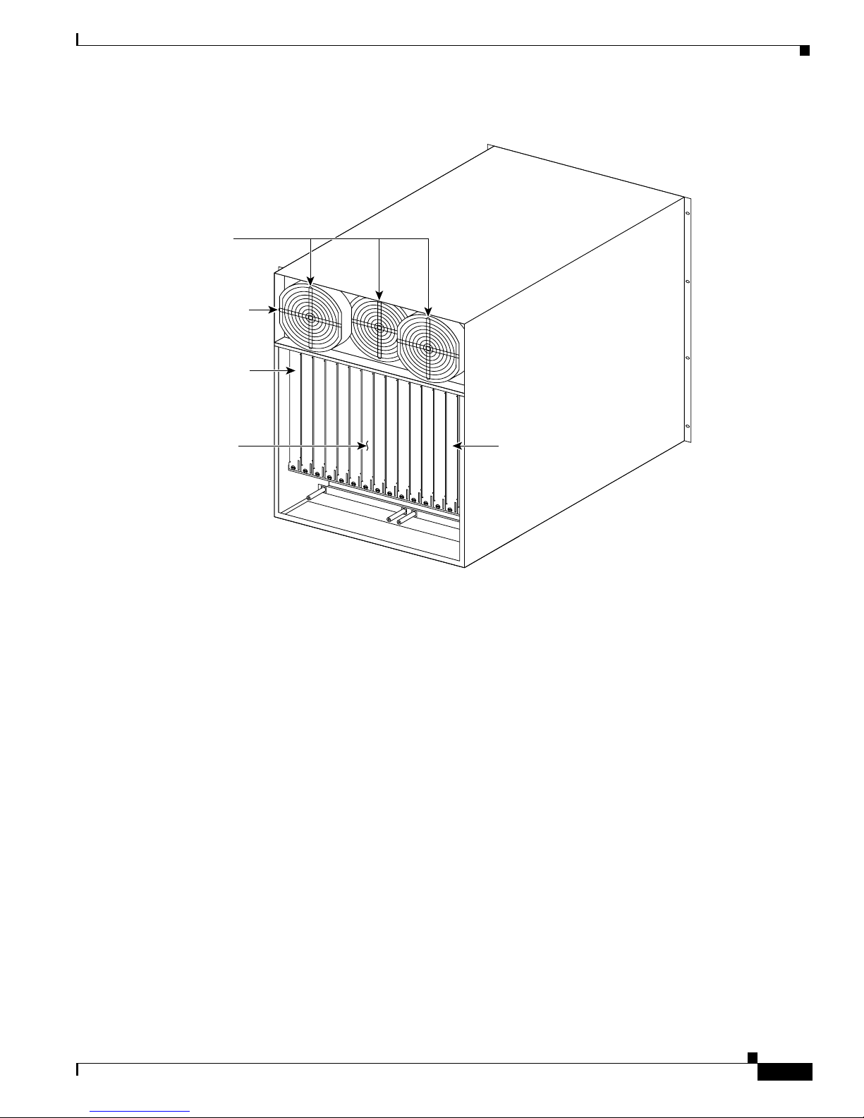
2-3
Cisco BPX 8600 Series Installation and Configurati on
Release 9.3.0, Part Number 78-10674-01 Rev. D0, July 2001
Chapter2 BPX Switch Physical Overview
BPX Switch Enclosure
Figure 2-2 BPX Switch Exterior Rear View
Node Cool i ng
A fan assembly with three six-inch 48 VDC fans is mounted on a tray at the rear of the BPX switch
shelf (see Figure 2-2). Air for cooling the cards is drawn through an air intake grille located at the
bottom in the front of the enclosure. Air passes up between the vertically-mounted cards and exhausts
at the top, re ar of th e ch assis.
All unused slots in the front are filled with blank faceplates to properly channel airflow.
Node DC Pow ering
The pri mary pow er for a BPX s witch node is -48 V DC which is bus e d a c ross the b a ckpla ne f or use by
all card slots. DC -t o- D C converters on e ach card con v er t th e -48V to lower voltages for use by the card.
The -48 VDC input connects directly to the DC Power Entry Module (PEM). The DC Power Entry
Module (see Figure 2-3) provides a circuit breaker and line filter for the DC input.
Nodes may be equipped with either a single PEM or dual PEMs for redundancy. PEMs are m ounted at
theback of the node below the backplane.A conduithookup box or an insulatedcover plate is provided
for terminating conduit or wire a t the DC power input. It is recommended that the source of DC for the
node be redundant and separately fused.
14 13 12 11 10
7
BCC-A
8
BCC-B
6
9
15
ASM
LM–
3/T3
LM–
3/T3
LM–
3/T3
LM–
3/T3
LM–
3/T3
LM–
3/T3
LM–
3/T3
LM–
3/T3
LM–
3/T3
LM–
3/T3
LM–
3/T3
LM–
3/T3
LM–
3/T3
LM–
3/T3
LM–
3/T3
5432
1
Fans
Slot #15
Slot #1
Back
Cards
Air
Exhaust
H8017
Page 82

2-4
Cisco BPX 8600 Series Installation and Configuration
Release 9.3.0, Part Number 78-10674-01 Rev. D0, July 2001
Chapter2 BPX Switch Physical Overview
BPX Switch Enclosure
Figure 2-3 DC Power Entry Module Shown with Conduit Box Removed
Optional AC Power Supply Assembly
Forapplications requiring operationfrom an AC power source,a n optional AC Power Supply Assembly
andshelf is available.It providesa sourceof –48 VDC from 208/240VAC input. A shelf, separatefrom
the BPX switch shelf, houses one or two AC Power Supplies and mounts directly below the node
cabinet. This provides a secure enclosure for the power supplyassemblies(supplies cannot be removed
without the use of tools).
Two of these supplies are usually operated in parallelfor fail-safe redundantoperation.The front of the
AC Power Supplies for the BPX switch includes two green LEDs to indicate correct range of the AC
input and the DC output for each individual supply (see Figure 2-4).
Figure 2-4 AC Powe r Supply Assembly Front View
+RTN
–48V
SAFETY
GROUND
CB1
ON
OFF
USE COPPER
CONDUCTORS ONLY
DC Terminal
Block
H8019
Plastic
Cover
DC
AC
Indicator
LEDS
H8145
Page 83

2-5
Cisco BPX 8600 Series Installation and Configurati on
Release 9.3.0, Part Number 78-10674-01 Rev. D0, July 2001
Chapter2 BPX Switch Physical Overview
Card Shelf Configuration
Card Shelf Configur ation
There a re fifteen vertical slots in the front of the BPX switch enclosure to hold plug-in cards (see
Figure 2-5).
The middletwo slots, slotsnumber 7 and number 8, are used for the primary and secondary Broadband
Controller Cards (BCC).
The right-most slot, number 15, is used to hold the single Alarm/Status Monitor Card.
The oth e r twelve slots, number 1 th ro ugh num ber 6 and number 8 through number 14, can be us e d for
the Netwo rk I n terf ace and Service In t erfa ce c ar ds.
Figure 2-5 BPX Switch Card Shelf Front View
BPX Switch Major Hardware Component Groups
There are four major groups of hardware components i n the BPX switch:
• Common Cor e Componen ts
• Network Interface Components
1234567
BCC-A8BCC-B
9 101112131415
ASM
status
port
13
act failstby
card
BNI-3/T3
81234
status
port
13
act failstby
card
BNI-3/T3
81234
status
port
13
act failstby
card
BNI-3/T3
81234
status
port
13
act failstby
card
BNI-3/T3
81234
status
port
13
act failstby
card
BNI-3/T3
81234
status
port
13
act failstby
card
BNI-3/T3
81234
LAN
BCC-15
81236
LAN
BCC-15
81236
status
port
13
act failstby
card
BNI-3/T3
81234
status
port
13
act failstby
card
BNI-3/T3
81234
status
port
13
act failstby
card
BNI-3/T3
81234
status
port
13
act failstby
card
BNI-3/T3
81234
status
port
13
act failstby
card
BNI-3/T3
81234
status
port
13
act failstby
card
BNI-3/T3
81234
status
alarms
DC ok
major minor
AB
ACO hist
ACO
history clear
act failstby
card
ASM
81237
H8020
act failstby
card
act failstby
card
22222222222
BNI-3/T3
81234
2
General
purpose
card slots
BCC/
PRI
BCC/
SEC
ASM
General
purpose
card slots
Page 84

2-6
Cisco BPX 8600 Series Installation and Configuration
Release 9.3.0, Part Number 78-10674-01 Rev. D0, July 2001
Chapter2 BPX Switch Physical Overview
BPX Switch Major Hardwa r e Component Groups
• Service Interface Co mp on en ts
• Power Supply Components
Table 2-1 lists these groups a nd their components along with a brief description of each.
For a detailed description of these components, see:
Table 2-1 BPX Switch Plug- In Card Summary
Card Card Name Where
BPX-
Common Core Component Group
BPX-BCC-32 Broadband Controller Card, operates with versions of System Software Rel. 7.0
and above, and requires32 Mbyte RAM for 8.1 andlater software. For redundancy
configuration, installed as a pair of BCC-32s. (System operation equivalentto
BCC-3.)
Front
BPX-BCC-bc Back card (also known as LM-BCC) used only with the BCC-32. Back
BPX-BCC-3-64 Broadband Controller Card, enhanced BCC-3. Note: BCC-3-64o r B CC-4 required
to support VSI and MPLS.
BPX-BCC-4 BroadbandController Card, operates with 8.4softwareand above. For redundancy
config urati on, inst alled a s a pair of BCC- 4s. Provides 64 Mbyte of RAM and
above. Supports up to 19.2 Gbps performance of BXM cards. Note: B CC-3-64 or
BCC-4requiredtosupportVSIandMPLS
Front
BPX-BC C- 3-b c Back card (also known as LM-BCC) used w i th B CC -4 . Back
BPX-A S M A lar m /Status M onitor C ar d. Front
BPX-ASM-BC Line Module - Alarm/Status Monitor. Back
Network Interface Component Group
BPX-BXM-T3-8
BPX-BXM-E3-8
BP:X-BXM-T3-12
BPX-BXM-E3-12
T3/E3cardwith8or12ports.Cardisconfiguredforuseineithernetwork
interface o r s er vi ce access (UNI) m od e and wi th either a T3 or E 3 in ter f ace .
Front
BPX-T3/E3-BC Backcard for use with a BXM-T3/E3-8 or BXM-T3/E3-12 Back
BPX-BXM-155-4
BPX-BXM-155-8
BXM OC-3 cards with 4 or 8 OC-3/STM-1ports, respectively. Card is configured
for us e in either ne twork i nterfa c e or s e rvic e access (UNI) m ode.
Front
BPX-MMF-155-4-B
C
BPX-SMF-155-4-BC
BPX-SMFLR-155-4BC
Backcards for BXM-155-4. Back
BPX-MMF-155-8-B
C
BPX-SMF-155-8-BC
BPX-SMFLR-155-8BC
Backcards for BXM-155-8. Back
BPX-BXM-622
BPX-BXM-622-2
OC-12 c ar d w ith 1or 2 OC- 12 /S TM-4po r ts. Card is con fi gu r ed for u s e in ei ther
network i nt er fa ce or s e rv ic e a ccess (UNI) m o de .
Front
BPX-BME Used for multicast connections. Used with SMF-622-2 backcard with port 1
looped to port 2 , t ra nsmit to receive, an d re cei ve to t ra nsm i t.
Page 85

2-7
Cisco BPX 8600 Series Installation and Configurati on
Release 9.3.0, Part Number 78-10674-01 Rev. D0, July 2001
Chapter2 BPX Switch Physical Overview
BPX Switch Major Hardware Component Groups
BPX-SMF-622
BPX-SMFLR-622
BPX-XLR-622-BC
Backcards for BXM-622. The XLR card supports a 1500nm interface Back
BPX-SMF-622-2-BC
BPX-SMFLR-622-2BC
BPX-SMFLR-622-2BC
Backcards for BXM-622-2 and BME (BME typically would use SMF-622-2). Back
BPX-BME Used for multicast connections. Used with SMF-622-2 backcard with port 1
looped to port 2 , t ra nsmit to receive, an d re cei ve to t ra nsm i t.
Back
BPX-BNI-3-T3 Broadband Network Interface Card (with 3 T3 Ports). Front
BPX-T3-BC Line Module, used with BNI-T3 for 3 physical T3 ports. (Configured for 3 ports) Back
BPX-BNI-3-E3 Broadband Network Interface Card (with 3 E3 Ports). Front
BPX-E3-BC Line Module, used with BNI-E3 for 3 physical E3 ports. (Configured for 3 ports). Back
APS Backcards and APS Redundant Backplane
The APS 1+1 feature requires two BXM front cards, an APS redundant frame assembly, and two redundant type BXM
backcards . Th e typ es o f r ed und an t bac kc ar d and b ac kp la ne s et s are:
• BPX-RDNT-LR-155-8 (8 port, long reach, SMF, SC connector)
• BPX-RDNT-LR-622 (single port, long reach, SMF, FC connector)
• BPX-RDNT-SM-155-4 (4 port, medium reach, SMF, SC connector)
• BPX-RDNT-SM-155-8 (8 port, medium reach, SMF, SC connector)
• BP X -RDNT-SM-622 (si ngle port, medium reach, SMF, FC conn ec tor)
• BPX-RDNT-SM-622-2 (2 port, medium reach, SMF, FC connector)
Each of the listed model numbers includes two single backcards and one mini-backplane.
The singl e bac kc ar ds and m in i- b ack plan e c an b e o rde re d as s p ares . Thei r m odel numbers are:
BPX-RDNT-BP= (common backplane for all redundant APS backcards)
BPX-LR-155-8R-BC= (for BPX-RDNT-LR-155-8)
BPX-LR-622-R-BC= (for BPX-RDNT-LR-622
BPX-SMF-155-4R-BC= (for BPX-RDNT-SM-155-4)
BPX-SMF-155-8R-BC= (for BPX-RDNT-SM-155-8)
BPX-SMF-622-R-BC= (for BPX-RDNT-SM-622)
BPX-SMF-622-2R-BC= (for BPX-RDNT-SM-622-2
Service Interface Component Group
BPX-E3-BC Line Module, used with BNI-E3 for 2 physical E3 ports. (Configured for 2 ports) Back
Power Supply Group
48 Volt DC Power Supply
Optional AC Power Supply
Table 2-1 BPX Switch Plug-In Card Summary (continued)
Card Card Name Where
Page 86

2-8
Cisco BPX 8600 Series Installation and Configuration
Release 9.3.0, Part Number 78-10674-01 Rev. D0, July 2001
Chapter2 BPX Switch Physical Overview
Service Expansion Sh elf PNNI
Service Expansion Shel f PNNI
The Cisco BPX S ES PN N I Controlle r is an optional Service Expansi on Shelf (S ES ) contro ller
connec ted diret ly to a BPX 86 00 seri es switch to pr o vi de Private Ne tw ork to Networ k Inte rface (P N NI)
signali ng and rout ing for the establ is h m ent of ATM s w itched vi r tu al circuits (S VCs) and Soft
Permanen t Virtual C ircuits (SP VCs ) o ve r a B P X 8 60 0 w id e a re a network. Ho w ev er, the SES can be
used in several WAN switching a pplications and is not limited to function only as a BPX SES PNNI
Controller
Every BPX 8600 series switch that deploys PNNI signaling and routing is collocated and attached to a
BPX SES PNNI Controller. The BPX SES PNNI Controller uses Cisco’s Virtual Switch Int erface ( VSI)
protocol to control the BPX switch for its networking application.
The BPX SES PNNI Controller is a 7-slot chassis that contains two Processor Switch Modules (PXMs)
that run th e P N N I a nd S V C software . One of the PXMs s erves as th e active processor, while the other
serves as th e st an db y. The PNNI controller is mo un t ed di r ecl ty atop t he BPX switch and cabled t o it
through e ither the OC-3 ATM interface (Figure 1-3) or the DS3 interfaces (Figure 1-4).
For instructions on installing a Service Expansion Shelf in a BPX 8620 rack and initially powering up,
see C is c o Service Ex pansi on Shelf (SES ) H ardware Inst allati on Guide . To configure an SES PNNI for
a BPX 8620, see the Cisco SES PNNI Controller Software Configuration Guide.
Optional Peripherals
At least o ne node in the netwo rk ( or networ k domain if a struc tured ne tw ork) mus t i nclude a Cis co WAN
Manager network management station (see Figure 2-6).
A Y-cable may be used to connect the LAN ports on the primary and secondary BCC Line Modules,
through a n AUI to the LAN network, because only one BCC is active at a time.
The serialControl port may be connectedto a dial-in modem for remote servicesupportor other dial-up
network managemen t ac ces s. T he serial Auxiliar y P ort c an be used f or in co m i ng an d ou tg oi ng d ata as
well as th e Au to d ial feature to rep or t alarms to Cisco TAC.
Page 87

2-9
Cisco BPX 8600 Series Installation and Configurati on
Release 9.3.0, Part Number 78-10674-01 Rev. D0, July 2001
Chapter2 BPX Switch Physical Overview
Optional Peripherals
Figure 2-6 Optional Peripherals Connected to BPX Switch
Modem
BCC
BCC-LM
active
Corporate network
AUI
AUI
StrataView plus
Printer
H8157
Two ports on BCC-LM can be used to connect up to two (2) of the peripherals shown.
*
*
BCC-LM
standby
Stratabus
Page 88

2-10
Cisco BPX 8600 Series Installation and Configuration
Release 9.3.0, Part Number 78-10674-01 Rev. D0, July 2001
Chapter2 BPX Switch Physical Overview
Optional Peripherals
Page 89

CHAPTER
3-1
Cisco BPX 8600 Series Installation and Configurati on
Release 9.3.0, Part Number 78-10674-01 Rev. D0, July 2001
3
BPX Switch Common Core Components
This chapt er d es cr ib es theBPX Swit ch ’s com mon c ore hardwar e compo nents:
• Broadband Controller Card (BCCs)
• 19.2 Gbps Operation wit h the BCC- 4V
• Alarm/Status Monitor Card
• BPX Switch StrataBus 9.6 and 19.2 Gbps Backplanes
The BP X switch Comm on Core gr oup include s the co m ponen ts shown in Figure 3-1:
• Broadband Controller Cards:
–
BCC-4 backcard
–
or BCC-32 and associated BCC15-BC backcard
Note The BCC-4 is required for VSI and MPLS features operation
• Alarm/Status Monitor (ASM), a Line Module for the ASM card (LM-ASM).
• StrataBus backplane.
The BCC- 4V provides a 16 x 32 crosspoin t sw i tch architec tu r e to extend th e B P X p eak s w i tch in g
capability from 9.6 up to 19.2 Gbps peak. The BCC-4V also provides 4 MBytes of BRAM and 128
MBytes of DRAM.
The functions of the common core components include:
• ATM cell switching.
• Internal node communication.
• Remote node communication.
• Node synchronization.
• Netwo r k man ag em e nt co m mu n ica ti on s ( Et he rnet ), local manage men t (RS-232).
• Alarm and status monitoring functions.
Page 90

3-2
Cisco BPX 8600 Series Installation and Configuration
Release 9.3.0, Part Number 78-10674-01 Rev. D0, July 2001
Chapter3 BPX Switch Common Core Components
Broadband Controller Card (BCCs)
Broadband Controll er Card (BCCs)
The Broadband Controller Card is a microprocessor-based system controller and is used to control the
overall operation of the BPX switch. The controller card is a front card that is usually equipped as a
redundant pair.
Slotsnumber 7 and number 8 are reservedfor theprimaryand secondary (standby)broadbandcontroller
cards. E ach broadband controller front card requires a c orresponding back card.
• For non-redundantnodes, a singleBCC is used in fro nt s lo t nu m b er 7 with its appr opr iat e backcard .
• For redundant nodes, a pair of BCCs of matching type, are used in front slot numbers 7 and 8.
Note The three types of BCCs wit h the ir pr o pe r backcards m ay be op er at ed together temporar il y
for maintenance purposes, for example, replacing a failed c ontroller card. Throughout a
netwo rk , individual BPX switches may have either a s ingle BCC-4V contro ller card or a
pair of the ident ical type of BCC.
Figure 3-1 Common Core Group Block Diagram
The term BCC is u s ed in this manual to ref er to the functio na l op er at io n of the Broad ba nd C on t ro ll er
Card. Whe n a differ en ce in o pe ra ti on d oe s o ccu r, the sp eci f ic type of BCC is sp ecified.
Broadband
controller
card
primary
Broadband
controller
card
redundant
Line
module-
ASM
Alarm/
status
monitor
Interface
card
Common
core
group
Interface
card
Interface
card
Alarm
outputs
H8023
Line
module-
BCC
Line
module-
BCC
EXT/INT
clock
NMS
port
StrataBus backplane
Page 91

3-3
Cisco BPX 8600 Series Installation and Configurati on
Release 9.3.0, Part Number 78-10674-01 Rev. D0, July 2001
Chapter 3 BPX Switch Common Core Components
Broadband Controller Card (BCCs)
The BCC-4V provides a 16 x 32 cross-point architecture that increases the peak switching capacity of
the BPX switch to 19.2 Gbps, with a sustained non-blocking throughput of 9.6 Gbps.
Features
The Broadband Controller Card performs these major system functions:
• Runs thesystem software for controlling,configuring, diagnosing,and monitoringthe BPX switch.
• Con tains th e crosspoint switch m atrix o perati ng at 800 Mbps pe r serial link or up to 1 600 Mbp s
(BCC-4V).
• Contains the arbiter which controls the polling each high-speed data port and grants the access to
theswitchmatrixforeachportwithdatatotransfer.
• GeneratesStratum3 system clocking and can synchronizeit to either a selectedtrunkor an external
clock input.
• Communicates configuration and control information to all other cards in the same node over the
backplan e communicat io n bus.
• Communicates with all other nodes in the network.
• Providesa communications processorfor an EthernetL AN port plus two low-speeddataports. The
BCC15-BC provides the physical interface for the BCC-32.
The BCC-3-BC provides the physical interface for the BCC-3-32M, BCC-3-64M, and BCC-4V.
Each Broadband Controller Card includes the following:
• 68EC040 processor operating at 33 MHz.
• 32 Mb or 64 MB option for BCC-4.
• 4 Mb of F lash EEPROM for downlo ad in g system soft w ar e.
• 512 K bytes o f BRAM for storing configuration data .
• EPROM for firmware routines.
• 68302 Utility p rocessor.
• SAR en gi ne pr o cessor opera ti ng at 33 MHz.
• Communication bus interfac e.
• HDLC processor for the LAN connect io n in ter f ace .
• Two RS-232 serial port interfaces.
Functional D escription
The BPX switch is a space switch. It e mploys a crosspoint switch for individual data lines to and from
each port. The switching fabric in each BPX switch consists of three elements for the BCCs (see
Figure 3-2):
• Centra l Ar b iter on each B CC .
• Crosspoint Switch.
–
16X32CrosspointSwitchingMatrixoneachBCC(2X[12X12])usedforBCC-4V.
• Seria l Inter f ace and LAN Inter face Modules on e ach B CC and on each Fun cti o n Mo d ul e.
Page 92

3-4
Cisco BPX 8600 Series Installation and Configuration
Release 9.3.0, Part Number 78-10674-01 Rev. D0, July 2001
Chapter3 BPX Switch Common Core Components
Broadband Controller Card (BCCs)
The arbiter polls each card to see if it has data to transmit. It then configures the crosspoint switching
matrix to m a ke the c on n ect io n between the t w o car ds. Each conn ection is un i di re cti on al an d has a
capacity of 800 Mbps (616.7 Mbps for c ell traffic plus the frame overhead).
Onlyoneconnectionatatimeisallowedtoanindividualcard.
Each card contains a Switch Interface Module (SIM) which merely provides a standardized interface
between the card and the data lines and polling buses. The SIM responds to queries from the BCC
indica tin g whether i t has data rea dy to transmit.
With the BPX switc h equi pp ed with tw o BCCs , the cell switch ing is comp letely redund ant in that there
are always two arbiters, two crosspoint switches, two completely independent data buses, and two
independen t polling buses.
The BCC inc or p orat es n o n- v ol at ile f las h EEPROM which permits new s oft w ar e rel eas e s to b e
downlo ad ed over the ne tw o rk and b attery-backup R A M (BRA M ) for st or in g user s y stem con f ig ur at io n
data. These memory features maintain system software and configuration data even during power
failur e s , eliminating th e need to d ow nload s oftware or re configure af t er the powe r returns.
The BPX sw it ch cell switchi n g is n ot synchronized to any external clock s; it run s at its o w n rate. No
switch fabric clocks are used to derive synchronization nor are these signals synchronized to any
external so ur ce s.
Node clocking is generated by the BCC. Because the BPX switch resides as an element in a
telecommunications network, it is capable of synchronizing to higher-stratum clocking devices in the
network and providing synchronization to lower stratumdevices. The BCC can be synchronizedto any
one of three different sources under software control:
• An in ter n al, high-stability oscillator.
• Derived clock from a BNI module.
• An exter n al clock sourc e con ne c t ed di r ect ly to t he BPX.
The BCC clock circuits provide clocking signals to every other card slot. If a function c ard needs to
synchr on ize its physica l i nterface to the BPX s w itch clo ck , i t can use th is timin g s ignal to derive t he
proper reference frequency. These reference frequencies include DS1, E1, DS3, and E3.
Page 93

3-5
Cisco BPX 8600 Series Installation and Configurati on
Release 9.3.0, Part Number 78-10674-01 Rev. D0, July 2001
Chapter 3 BPX Switch Common Core Components
Broadband Controller Card (BCCs)
Figure 3-2 BCC4V Block Diagram
Front Panel D escription
The BCC front pane l has fou r Led , three ca rd st atus L EDs, and a LAN LE D . (See F igure 3-3 and
Table 3-1.)
S
s6392
BCC-A
Arbiter
SIU
TX data-2A
RX data-2A
TX data-12A
RX data-12A
TX data-1B
RX data-1B
RX data-2B
TX data-2B
TX data-12B
RX data-12B
Polling bus-A
Polling bus-B
TX data-1A
RX data-1A
I/O
module 1
DRSIU
I/O
module 2
DRSIU
I/O
module 12
DRSIU
BCC-A
16 x 32 Xpoint switch 16 x 32 Xpoint switch
Arbiter
SIU
S6393
Table 3-1 BCC Front Panel Indicators
No Indicator F unc tion
1 LAN Indicates there is data activity over the Ethernet LAN port.
2 card - act C ar d a ct iv e LED ind ica tes this BCC is online and a ctively
controlling the node.
3 card - stby Card standby LED indicates this BCC is offline but is ready to
take over control of the node a t a moments notice.
4 card - fail CardfailLED indicatesthis BCC hasfailedthe internal self-test
routine and needs to be reset or r ep la ced.
Page 94
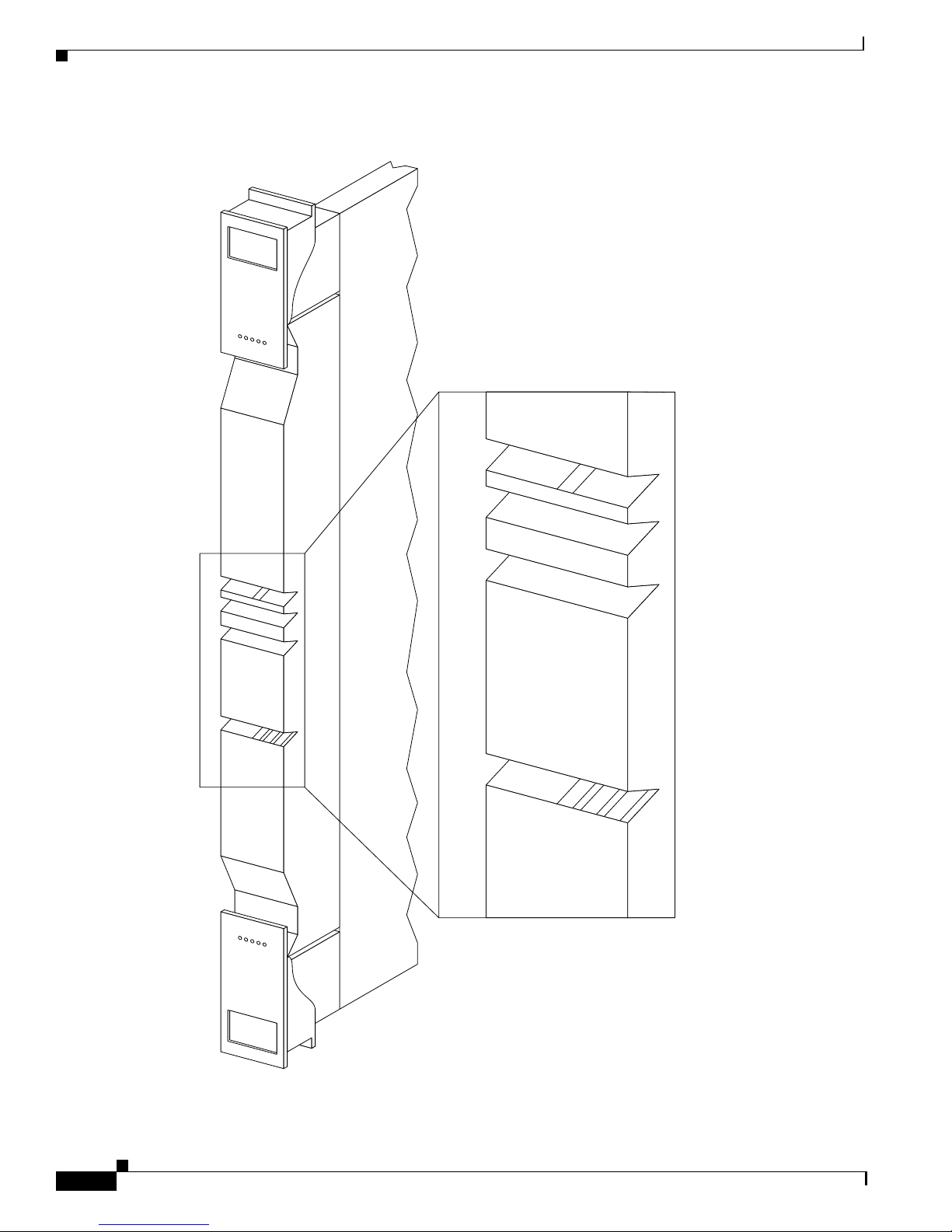
3-6
Cisco BPX 8600 Series Installation and Configuration
Release 9.3.0, Part Number 78-10674-01 Rev. D0, July 2001
Chapter3 BPX Switch Common Core Components
Broadband Controller Card (BCCs)
Figure 3-3 BCC Front Pane l
LAN
act failstby
card
BCC
H8024
LAN
act failstby
card
Page 95

3-7
Cisco BPX 8600 Series Installation and Configurati on
Release 9.3.0, Part Number 78-10674-01 Rev. D0, July 2001
Chapter 3 BPX Switch Common Core Components
19.2 Gbps Operation with the BCC-4V
The BCC runs self-tests c ontinuously on internal functions in the background and if a failure is
detected, the fail LED is lighted. If the BCC is configured as a redundant pair, the off-line BCC is
indicated by the lighted stby LED. Th e stby LE D also flashes when a s oftware downloa d or standby
update is in progress. The LAN LED indicates activity on the Ethernet port.
19.2 Gbps Operation with the BCC-4V
To operate the BPX switch at up to a 19.2 Gbps peak throughput, these components are required:
• A 19.2 Gb p s back pl an e
• BCC-4V or later controller cards
• OneormoreBXMcards
• Release 8.4.00 or later switch software
• A backplane NOVRAM that is programmed to identify the backplane as a 19.2 Gbps backplane.
Switchsoftwaredoes not allownode operationat 19.2 Gpbs unless it can readthe backplane NOVRAM
to verif y that the bac kp lane is a 19.2 G bp s b ackpla ne.
The 19.2 bac kp la ne can b e vis u all y id en tif i e d by th e small white c ar d slot f an fu ses at the bottom rear
of the backplane. These fan fuses are approximately 1/4 inch high and 1/8 inch wide. The 9.6 Gbps
backplane does not have these fuses.
If the BP X switch is a late mo del, then a 19.2 Gbp s b ackpla ne is installed. You ca n be verify this by
running the despond comm an d which will d isp lay “Word #2 =0001” if the backplane NOVRAM has
been programmed. If anything else is displayed, visually check the backplane for the fuses.
If the backplane is a 19.2 Gbps backplane, but the backplane NOVRAM has not been set to display
Word #2 =0001, then you may use the cnfbpnv command to program the NOVRAM:
Step 1 Enter cnfbpnv. The interface responds:
Are you sure this is a new backplane (y/n).
Step 2 Enter y
Step 3 Confirm that the change has been m ade by entering dspbpnv to confirm the response:
Word #2 =0001
Note If the change does not take place, it will be necessary to change the backplane
NOVRAM. Contact Cisco Customer Service.
Step 4 Enter switchcc to make switch software recognize the change.
If t he backplane is no t a 1 9.2 G bp s ba ck pl an e, co nt act C ust omer Cust ome r S ervi ce.
Back Cards f or t h e BCC-4V
The backcardsfor the Broadband ControllerCard serveas an interface betweenthe BPXswitch and the
BPX switch ne twork m anagement system .
Page 96

3-8
Cisco BPX 8600 Series Installation and Configuration
Release 9.3.0, Part Number 78-10674-01 Rev. D0, July 2001
Chapter3 BPX Switch Common Core Components
19.2 Gbps Operat ion with the BCC-4V
For the BCC-4V, the backcar d is the BCC-3-BC. (T hese backcards ar e also k nown as the BCC
backcards ).
TheBCC-4V providesimportantfeaturessuch as support for upto 19.2Mbpspeak operation with BXM
cards. Both BCCs in a node should be of the same type.
The backc ard pr ov i de s thes e interfaces:
• An 802.3 A IU (Ethernet) interfa ce for connect ing the node to a CWM N MS.
• A serial RS-232 Control Port for connecting to a VT100-compatible terminal or modem.
• A serial RS-23 2 Auxilia ry P o rt for co nn ecting to an externa l printer.
• Extern al cl ock i npu ts a t T 1 or E1 r at es, output at 8 kHz.
The face plate connectors are described in Table 3-2 and Table 3-3 and shown in Figure 3-4. The
BCC15-BC is shown on the left and the BCC-3-BCC is shown on the right.
For specifications on cabling, refer to Chapter 32, BPX Switch Cabling Summary .
Table 3-2 BCC15-BC Backca rd for BCC-32, Connectors
Connector Function
CONTROL A DB25 connector for a VT100 or equivalent terminal for a basic terminal
connection enabling you to use the command line interface commands. You can
also conne ct to a di al- i n m odem for remote ser v ice support or ot he r ne tw o rk
manageme nt dial-up access . Th is i s a bidirectiona l R S2 32 communic ati on s po rt .
It is not used for CWM Network Management; the LAN connector is used for
CWM Network Management.
AUXILIARY A DB25 connector for a system printer. This is a one-way, RS232 outgoing port.
XFER TMG DB15 connector that supplies an 8-kHz timing signal (RS422 type output that is
synchronized to the BPX s witch system clock.)
EXT TMG A 75-ohm BNC connectionfor clock input.An E1 source with 75 ohm impedance
typically uses this connector. If the shield on the cable needs grounding, slide the
BCCbackcardoutandjumpedconnectorJP1acrossitstwopins.
EXT TMG DB15 connector for a primary and optional redundant external source of system
clock. A T1 source with 100 ohm impedance or an E1 source with 100/120 ohm
impedance typically use this connector.
LAN A DB15 Ethernet LAN connection for connecting to a CWM NMS. Youcan a lso
connect a ter mi na l (o r NMS other than CWM) to the B P X sw i tch LAN p o r t via
Ethernet. However, only the CWM NMS provides full management
configuration and statistics ca pabilities via SN M P and TFTP.
Page 97

3-9
Cisco BPX 8600 Series Installation and Configurati on
Release 9.3.0, Part Number 78-10674-01 Rev. D0, July 2001
Chapter 3 BPX Switch Common Core Components
19.2 Gbps Operation with the BCC-4V
Table 3-3 BCC-3-BC Back Card for BCC-4V
Connector Function
CONTROL A DB25 connector for a VT100 or equivalent terminal for a basic terminal
connect io n using com m an d line inter fa ce comm ands. You can also connect to a
dial-inmodem for remote servicesupportor other network managementdial-up
access. This is a b id i re cti on al RS2 3 2 comm u ni cat io ns por t. This is not used for
CWM Network Management; the LAN connector is used for CWM Network
Management.
AUXILIARY A DB25 connectorfor a system printer.This is a one-way, RS232 outgoing port.
LAN A DB15 Ether ne t LAN con ne ct io n for conn ect in g to a CW M NM S . A termin al
or NMS ot h er than CWM ca n als o b e c on n ected to the BPX switch LAN p ort
via Ethernet. However, only the CWM NMS provides full management
config ur at io n a n d s tat ist ics capabilit ies via S N M P an d T FTP.
EXT TMG A 75-ohm BNC connection for clock input. An E1 source with 75 ohm
impedance typically uses this connector. If the shield on the cable needs
grounding, slidethe BCC back card out andjumper connectorJP1 acrossits two
pins.
EXT 1 TMG DB15 connector for a primary and optional redundant external source of system
clock.A T1 source with 100 ohm impedanceor an E1 source with 100/120 ohm
impedance typically use this connector.
EXT 2 TMG Provides for an external clock source redundant to the EXT 1 TMG source.
Page 98

3-10
Cisco BPX 8600 Series Installation and Configuration
Release 9.3.0, Part Number 78-10674-01 Rev. D0, July 2001
Chapter3 BPX Switch Common Core Components
19.2 Gbps Operat ion with the BCC-4V
Figure 3-4 BCC15-BC and BCC-3-BC Backcard Face Plate Connectors
Another function of the line module back card is to provide two low-speed, serial communications
ports, as describe d in Table 3-3:
CONTROL port
A bidirectional port for connecting the BPX switch to a local terminal or to a modem for a remote
termin al di al- in connect io n.
AUXILIARY port
An output only port, typically used to connect to a printer dedicated to printing logs.
BCC
H8025
Control Port
(DB25)
C
O
N
T
R
O
L
A
U
X
I
L
I
A
R
Y
X
F
E
R
T
M
G
E
X
T
T
M
G
E
X
T
T
M
G
L
A
N
Auxiliary Port
(DB25)
T1 or E1
External timing out
(DB15)
External timing
(E1, BNC)
External timing
(E1, BNC)
T1 or E1
External timing in
(DB15)
Ethernet for
Cisco WAN Manager
(DB15)
L
A
N
E
X
T
1
T
M
G
E
X
T
2
T
M
G
External timing 1
(DB15)
External timing 2
(DB15)
BCC15-BC BCC-3-BC
Control Port
(DB25)
C
O
N
T
R
O
L
A
U
X
I
L
I
A
R
Y
Auxiliary Port
(DB25)
Ethernet for
Cisco WAN Manager
(DB15)
E
X
T
T
M
G
BCC-3
BC
Page 99

3-11
Cisco BPX 8600 Series Installation and Configurati on
Release 9.3.0, Part Number 78-10674-01 Rev. D0, July 2001
Chapter 3 BPX Switch Common Core Components
Alarm/Status Monitor Card
The Cisco WAN Manager NMS is connected to the LAN port on the BCC backcards. When control is
providedvia an Ethernet i nterface,you configurethe node IP address by using the cnfla n command for
theBPX switch.For redundancy,alsoconfigurethe LAN ports on bothBCC backcards,each connected
to an AUI ad ap te r.
The LAN port of the primary Broadband Control Card is a ctive. If the secondary Broadband Control
Card bec om es p ri mar y ( act iv e) , t he n its LAN port bec o mes active. The C isco WAN Manager
workstation will automatically try to restore communications over the LAN and will interface with the
newly a ctive Broadband Controller Card.
For small netwo rks, one Cis c o WAN Manager works tation is adequat e to c ollect sta tistics and prov ide
network m an ag em en t. F o r larger networks ad diti on al Ci s co WAN M an ag er workstation s may be
required. Refer to the Cisco WAN Manager Operations Guide.
Alarm/Status Monitor Card
The Alarm/Status Monitor (ASM) card is a front card. Only one is required per node and it is installed
in slot 15 of the BPX switch. It is used in conjunction with an associated back card, the Line Module
for th e ASM (LM-ASM) card.
The AS M and LM- A SM card s are non-crit ica l cards used for moni tori ng the operat io n of the node an d
not direct ly in v ol ve d in s y stem operation. Th er efo re , t he re is no pro v isi on o r re quirement fo r car d
redundancy.
Features
The ASM card provides a number of support functions for the BPX switch:
• Telco compatible alarm indicators, controls, and relay outputs.
• Node power monitoring (including provision for optional external power supplies).
• Monitoring of shelf cooling fans.
• Monitoring of shelf ambient temperature.
• Sen s in g for th e presence o f ot he r cards that are installed in the BPX sw i tch.
Functional D escription
BPX switch system software commands the ASM cardto activate the major and minor alarm indicators
and relays.
There are fou r s ig n ifica nt circuits cont ro ll ed b y th e A SM processor:
• Alarm
The alarm monitor controls the operation of the front panel alarm LEDs and ACO and history
pushbuttons as well as the alarm relays that provide dry contact closures for alarm outputs to
customer c on n ect io ns.
• Power supply monitor
The power supply mo n itor circuit monitors t he status of the - 48 V input to the shelf on each o f the
two power b u s e s , A an d B. The status of both the A bu s and B p ow e r bus is displayed on the ASM
front panel .
Page 100

3-12
Cisco BPX 8600 Series Installation and Configuration
Release 9.3.0, Part Number 78-10674-01 Rev. D0, July 2001
Chapter3 BPX Switch Common Core Components
Alarm/Status Monitor Card
• Fan and temperature monitor
Each of the three cooling fans is monitoredby the fan monitor circuit which forwards a warning to
the BPX switch system software if any fan falls belowa presetRPM. Cabinetinternal temperature
is also monitored by the ASM which sends the temperature to the system software to be displayed
on the NMS terminal. The range that can be displayed is 0 degrees to 60 degrees Centigrade.
• Card de t ect io n.
Front Panel D escription
The front panel displays the status of the node a nd any major or minor alarms that might be present.
Figure 3-5 il lu str at es t he f ro n t pan el o f th e AS M card. Eac h fro nt p an el feature is descr ib ed i n
Table 3-4.
Table 3-4 ASM Front Panel Cont rols and Indicators
No
Controls/
Indicator Function
1 alarms LEDs A red major alarm and a yellow minor alarm indicator to display the
status of th e l oc al no d e. In g en er al , a m aj or al ar m i s affec ts se rv ic e
whereas a mino r al ar m i s a fa ilu r e tha t d o es no t a ffect se r vi ce.
2 dc LEDs Two green LEDs display the status of the two DC power busses on the
Stratabus backplane. ON indicates voltage within tolerance. OFF
indicate s an out-of-toleran ce voltage.
3 ACO/hist LEDs ACO LED (yellow) lights when you press the front panel ACO
pushbutto n. Hist ory LED (gre en ) indicat es an alarm has been detected
by the ASM at some time in the past but might not be clear at present
time.
4 ACO s w it ch When ope ra ted , releases the au d ib le alarm relay.
5 histor y cl ear
switch
Extinguishes the historyLED if the alarm condition has cleared. If the
alarm is s ti ll present when the history c lear switch is thrown, th e
histor y LED will s tay lit.
6 card st at us L ED s Act iv e (green ) i nd i cat es the car d is onlin e and c lea r of alar ms . S tan d by
(yellow ) in d ic ates the card is offline. Fa ul t (r ed ) in di cates a card fai lu r e
is detec ted by the car d self-test dia gn o s ti cs .
 Loading...