

Page 1
Video Conferencing &
Recording Using Cisco BE6000
Cisco Validated Design Guide
© 2015 Cisco Systems, Inc. All rights reserved. (10/12/15)
October 2015
Page 2
Preface
PAGE 2
Page 3
Preface
PAGE 3
Page 4
Preface
PAGE 4
Cisco Validated Designs (CVDs) provide the foundation for systems design based on common use cases
or current engineering system priorities. They incorporate a broad set of technologies, features, and
applications to address customer needs. Cisco engineers have comprehensively tested and documented
each CVD in order to ensure faster, more reliable, and fully predictable deployment.
Documentation for Cisco Validated Designs
Cisco Preferred Architecture (PA) Design Overview guides help customers and sales teams select the
appropriate architecture based on an organization's business requirements; understand the products that
are used within the architecture; and obtain general design best practices. These guides support sales
processes.
Cisco Validated Design (CVD) guides provide detailed steps for deploying the Cisco Preferred
Architectures. These guides support planning, design, and implementation of the Preferred Architectures.
Cisco Collaboration Solution Reference Network Design (SRND) guide provides detailed design options for
Cisco Collaboration. The SRND should be referenced when design requirements are outside the scope of
Cisco Preferred Architectures.
Many CVD guides tell you how to use a command-line interface (CLI) to configure network devices. This
section describes the conventions used to specify commands that you must enter.
Commands to enter at a CLI appear as follows:
configure terminal
Commands that specify a value for a variable appear as follows:
ntp server 10.10.48.17
Commands with variables that you must define appear as follows:
class-map [highest class name]
Commands at a CLI or script prompt appear as follows:
Router# enable
Long commands that line wrap are underlined. Enter them as one command:
police rate 10000 pps burst 10000 packets conform-action set-discard-class-
transmit 48 exceed-action transmit
If you would like to comment on a guide or ask questions, please email
collab-mm-cvd@external.cisco.com.
Page 5
CVD Navigator
PAGE 5
The CVD Navigator helps you determine the applicability of this guide by summarizing its key elements: the
Cisco Preferred Architecture for
Midmarket Collaboration,
Design Overview
Cisco Preferred Architecture for Video,
Design Overview
To view the related CVD guides,
click the titles or visit the following site:
http://www.cisco.com/go/cvd/collaboration
Unified Communications
Using Cisco Business Edition
6000 CVD
use cases, the scope or breadth of the technology covered, the proficiency or experience recommended,
and CVDs related to this guide. This section is a quick
reference only. For more details, see the Introduction.
This Cisco validated design guide should be started after
deploying the Unified communications using cisco
BE6000 cisco validated design guide.
This guide addresses the following technology use
cases:
—Organizations want
to reap the budgetary and productivity gains that a
remote workforce allows, without compromising
the benefits of face-to-face interaction. They need
a solution that is fast to deploy and easy to manage
from a central location, without replicating costly
components at their remote sites.
For more information, see the “Use Cases” section in
this guide.
This guide covers the following areas of technology and products:
Video call agent
Desktop video endpoints
Multipurpose room systems
Video Conference Bridge
Video Conference Management Systems
Video Conference Scheduling Systems
Video Recording Systems
Session Initiation Protocol (SIP) signaling
For more information, see the “Design Overview” section in this guide.
Page 6

CVD Navigator
PAGE 6
This guide is for people with the following technical proficiencies—or equivalent experience:
—1 to 3 years configuring voice devices and video single-screen endpoints,
supporting telephony and video applications, and troubleshooting.
Page 7
Introduction
PAGE 7
Businesses around the world are struggling with escalating travel costs. Growing corporate expense
accounts reflect the high price of travel, but travel also takes a toll on the health and well being of
employees and their families. Often, the only way to solve a difficult problem is to fly an expert to the
location to see the issue and discuss it with the people at the site. When an expert cannot see what is
being described, the resolution of a complex problem often takes much longer.
Workers at remote sites often feel isolated from their departments because they do not spend enough
face time with their peers and they feel disconnected from the decision-making process. This isolation can
lead to lower job performance and less job satisfaction from employees who do not work at the
organization’s main location.
Hiring process can be very lengthy and costly, especially when candidates are located in other cities or
when multiple people are involved in the interview process. Organizations with video conferencing systems
in their offices can reduce expenses and time by bringing candidates into the nearest facility and allowing
interviews to be conducted both in person and over video.
The face-to-face interaction during video collaboration meetings helps to boost information retention,
promotes increased attention span, and reduces participant confusion. The nonverbal cues experienced in
a visual meeting are sometimes more important than what is actually spoken.
Use Case: Video Collaboration with Desktop and Multipurpose Room
Systems
Organizations want to reap the budgetary and productivity gains that a remote workforce allows—without
compromising the benefits of face-to-face interaction. They want to allow the flexibility for an employee to
work across remote sites while still maintaining the familiar in-person contact of their peers and managers.
They also want to enrich the collaboration experience in their meeting rooms, boardrooms, auditoriums
and other shared environments. A solution is needed that is fast to deploy and easy to manage from a
central location without replicating costly components at their remote sites.
This design guide enables the following capabilities:
Single cluster centralized design to simplify deployment and management while saving on
infrastructure components.
URI and numeric dialing to allow video-enabled IP phones to call room systems.
Provisioning the videoconference bridge for the site.
Conference resource optimization, management and scheduling.
Instant, Personal and Scheduled Collaboration Meeting Rooms (CMR) Conferences.
Captures video and presentations for live streaming and video-on-demand (VoD) viewing.
Page 8
Introduction
PAGE 8
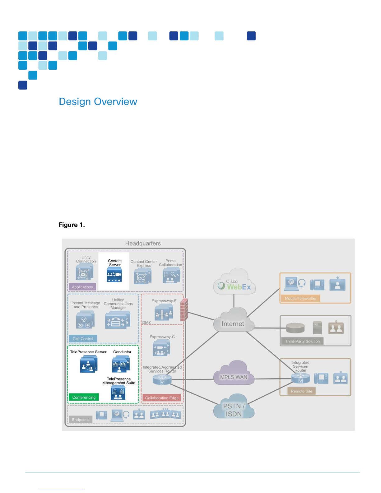
An end-to-end video-collaboration solution incorporates a full suite of endpoints, infrastructure
components, and centralized management tools.
Cisco Preferred Architecture
Cisco Preferred Architectures provide recommended deployment models for specific market segments
based on common use cases. They incorporate a subset of products from the Cisco Collaboration portfolio
that is best suited for the targeted market segment and defined use cases. These deployment models are
prescriptive, out-of-the-box, and built to scale with an organization as its business needs change.This
prescriptive approach simplifies the integration of multiple system-level components and enables an
organization to select the deployment model that best addresses its business needs.
The Cisco Preferred Architecture (PA) delivers capabilities that enable organizations to realize immediate
gains in productivity and add value to their current voice deployments.
High level block diagram
Page 9

Introduction
PAGE 9
Network Considerations
If you already have an IP network in place for voice, your natural next step is to deploy video over IP. Many
organizations run video systems in a mixed environment as they move from older systems to newer ones,
based on IP. As older systems migrate off of ISDN, significant quality improvements and cost savings will
be seen.
Unified communications running over IP offers lower costs, easier management, remote monitoring, and
control from across the network. It also provides higher bandwidth for calls, enabling superior audio and
video quality while providing tighter integration into the corporate IT mainstream.
With an IP network, the ongoing costs of running video calls are minimal because you only have to pay for
maintenance and technical support. When return on investment (ROI) for the initial deployment is met, any
additional costs are essentially free. Because there is no incremental cost involved, employees and
managers are more likely to use the technology. As usage goes up, payback times go down, further
boosting the ROI.
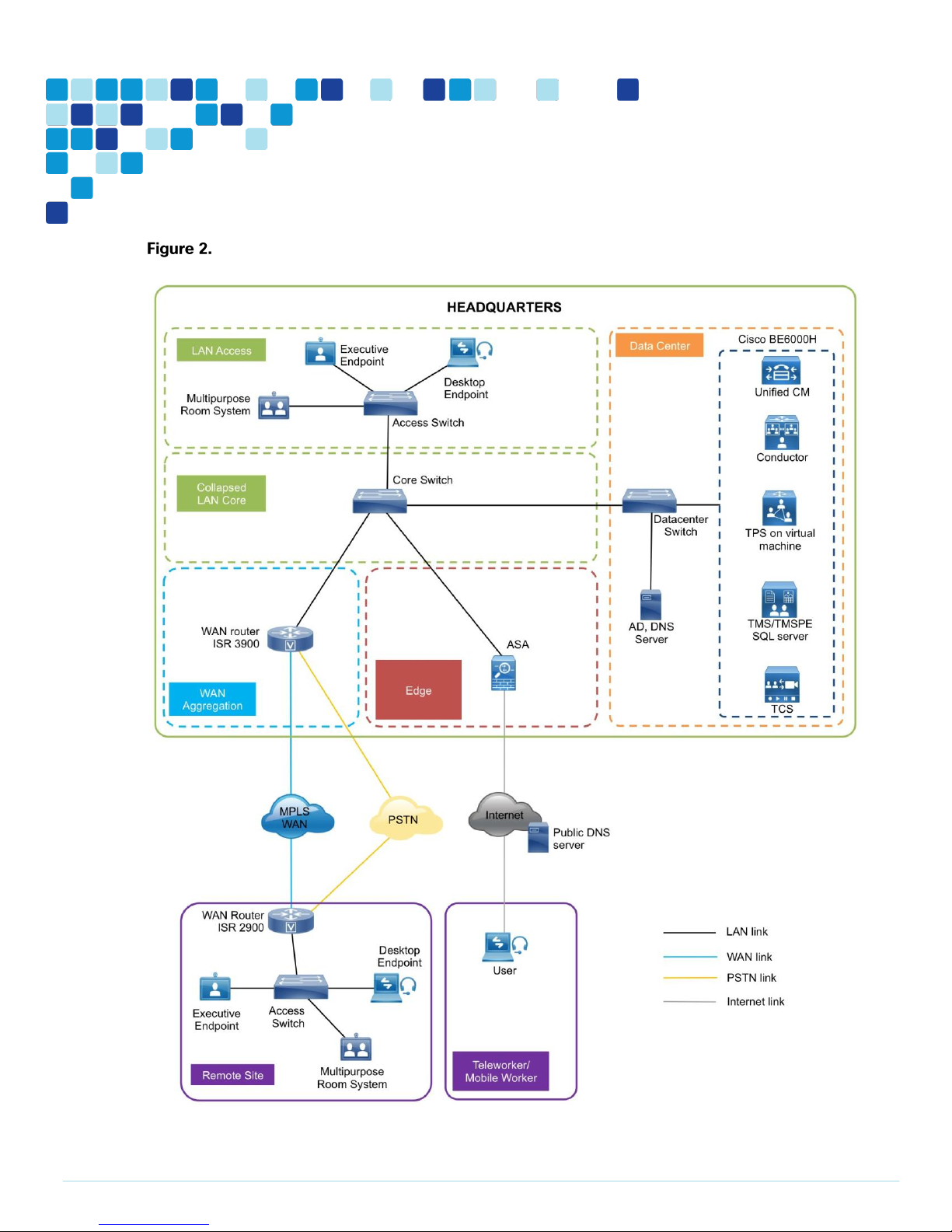
Solution Details
The Video Conferencing CVD includes the following components:
Cisco Unified Communications Manager (Unified CM), for call control and SIP endpoint registrations
Desktop (Cisco 8800 series IP phones, Cisco Jabber and Cisco Desktop Collaboration Experience DX
series) and multipurpose (Cisco TelePresence SX 10 and 20 Quick Set) systems for placing and
receiving calls
Cisco TelePresence Server on Virtual Machine, Cisco TelePresence Conductor, Cisco TelePresence
Management Suite (TMS) and Cisco TelePresence Management Suite Provisioning Extension
(TMSPE) for reservation-less, instant CMR conference (formerly ad-hoc conference), personal CMR
conference (formerly rendezvous/static conference) and scheduled CMR conference
Cisco TelePresence Content server for video and conference recording
Network Time Protocol (NTP) server for logging consistency
Page 10
Introduction
PAGE 10
High level network diagram
Page 11
Introduction
PAGE 11
Cisco Unified Communications Manager
Unified CM serves as the software-based, call-processing component of Cisco Unified Communications.
Additional data, voice, and video services, such as unified messaging, rich media conferencing,
collaborative contact centers, and interactive multimedia response systems, interact through Cisco Unified
Communications Manager open-telephony application program interface (API).
Unified CM is the primary call agent in this CVD. Unified CM supports session initiation protocol (SIP), and
the configurations in this document use SIP as the signaling protocol for endpoints.
Cisco Video and TelePresence Endpoints
Cisco video endpoints provide IP video telephony features and functions similar to IP voice telephony,
enabling users to make point to point and multipoint video calls. Cisco video endpoints are classified into
families based on the features they support, hardware screen size, and environment where the endpoint is
deployed.
There are two types of endpoints mentioned in this document:
Windows/Mac/Android/IOS and the Cisco 8800 series IP phones and DX650 endpoints are capable
of transmitting video by means of the built-in front-facing camera or a USB attached external
camera. The Cisco TelePresence System DX70 and 80 endpoints take the personal desktop solution
to a next level of experience with support for content sharing, mobile and remote access.
that can turn any display into a powerful Cisco TelePresence system. SX20 Quick Sets are designed
for HD video and multiparty conferencing, with the flexibility to accommodate various room sizes.
—The Cisco TelePresence SX10 and SX20 Quick Sets are flexible integrators
—Cisco Jabber software-based clients, such as Cisco Jabber for
Cisco TelePresence Server on Virtual Machine
The Cisco TelePresence Server is an innovative software solution enabling high-quality standards-based
conferencing for mobile, desktop and immersive endpoints. Compatible with a range of hardware
platforms, the TelePresence Server is a versatile, highly scalable solution for midmarket and larger
enterprise customers. TelePresence Server on Virtual Machine, which runs on the Cisco Unified
Computing System (Cisco UCS) or third party specification-based server platforms, offers a virtualized
solution.
Instant, personal and scheduled CMR conferences use TelePresence Server on Virtual Machine to ensure
that endpoints can communicate in a single conference at the highest possible bit rates and resolutions,
without loss of quality.
Cisco TelePresence Conductor
Cisco TelePresence Conductor software simplifies multiparty video communications, orchestrating the
different resources needed for each conference as required. It allows the video network to be configured
so that conferences can be easily provisioned, initiated, and accessed. TelePresence Conductor simplifies
and enhances conference resource management, making conferences easy to join and administer. It uses
Page 12

Introduction
PAGE 12
knowledge of all available conferencing resources and their capabilities to help ensure dynamic, intelligent
conference placement and optimized resource usage. Conductor is a mandatory component when
TelePresence Server for Virtual Machine is used for conferencing.
Cisco TelePresence Management Suite
Cisco TelePresence Management Suite (Cisco TMS) enables a variety of scheduling features and
management functionality within Cisco Unified Communications including Personal and Scheduled
Collaboration Meeting Rooms (CMR) Conferences.
CMRs are reserved virtual spaces that have a set video address. Users can call in to that address at any
time to start a meeting. Creation of a CMR requires deployment of TelePresence Conductor with Unified
CM, configured with one or more conference bridge pools and Service Preferences. TMS is required to
configure Personal and Scheduled CMR Conferences.
Cisco TelePresence Content Server
Cisco TelePresence Content Server adds the functionality of recording videos and conferences and then
let them be available as video-on-demand (VoD) for later viewing. There are two scenarios that can be
achieved by having the TelePresence Content Server in the solution:
Dial into the TelePresence Content Server and self record
Record instant CMR conferences
Cisco TelePresence Content Server is trunked to the Unified CM and a dedicated directory number is used
for calls towards the TCS.
Dial Plan
These design uses, single-cluster, centralized call processing. The endpoints use a seven-digit phone
number for dialing, which preserves the capability to receive calls from devices that only support only
numeric dialing. The numbers are in the following pattern:
For URI dialing the endpoints are assigned the URI in the following pattern:
The domain used in this document is .
As your solution grows, you may need to acquire a security certificate from a public certification authority.
Choose a domain name in this step with a valid Internet domain suffix (.com, .edu etc) to ensure that your
system is ready for this requirement.
For instant CMRs, TelePresence Conductor is added as a media resource on the Unified CM.
For personal CMR conferences, TelePresence Conductor is SIP trunked to Unified CM. Personal CMR
conferences can have both numbers and URIs. In this document, every user has a dedicated number and
Page 13

Introduction
PAGE 13
URI configured on the TelePresence Conductor via the TMS. The CMR numbers and URIs used in the
following pattern:
For scheduled CMRs, TelePresence Conductor is SIP trunked to Unified CM. In this document, whenever a
user schedules a conference, a randomly generated number is assigned to the scheduled conference for
the users to dial in. The scheduled CMR numbers are used in the following pattern:
For recording, TelePresence Content Server is SIP trunked to Unifed CM. For self-video recording the
user has to dial a preconfidured DN. For recording an instant CMR conference the user will have to add
TCS DN as an additional participant. In this document, this preconfigured DN is in the following pattern:
Page 14
Deployment Details
PAGE 14
This guide is divided into multiple sections: server installations and deploying CMR Premises. Each section
has procedures and steps needed to configure the system from the ground up.
For customers who want to deploy both conferencing and recording in their environments, please follow all
the procedures in all the process boxes.
For customers who want to deploy only conferencing without the recording capability, please skip the
precedures labelled as (recording only).
For customers who want to deploy only recording without the conferencing capability, please follow the
procedures labelled as (recording only).
For the installation of Cisco Unified Communications Manager (Unified CM), refer the “Installing the Cisco
Unified CM” process in the Installation Guide for Cisco Business Edition 6000.
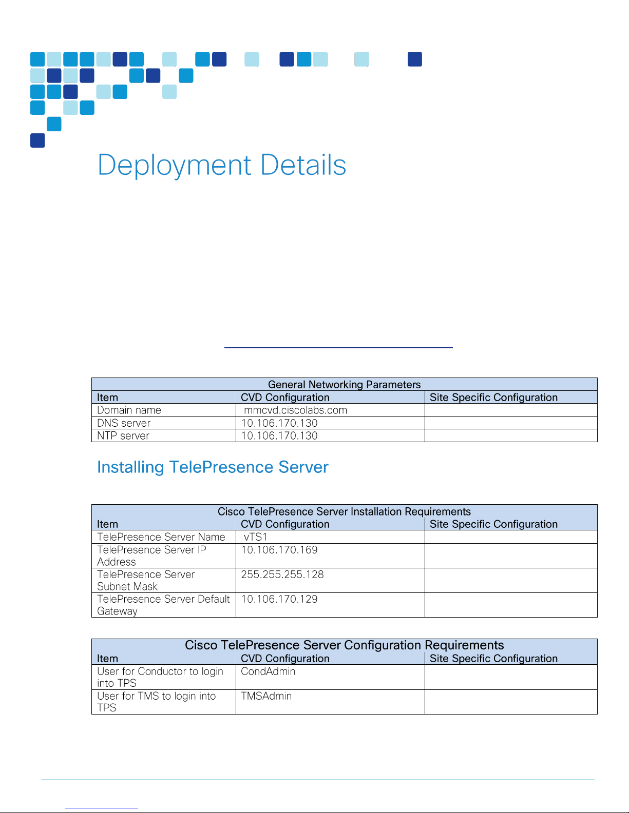
Easy Access Configuration Sheet
Easy Access Configuration Sheet
Page 15
Deployment Details
PAGE 15
1. Configure Cisco Business Edition 6000 connectivity to LAN
2. Deploy OVA to host
3. Configure the VM guest
This process guides you through installing the TelePresence Server Virtual Machine.
Configure Cisco Business Edition 6000 connectivity to LAN
Deploy OVA to host
The Cisco Business Edition 6000 is connected to a switch in the data center.
Using the user account that has ability to make configuration changes, log in to the data
center switch.
If there is a previous configuration on the switch port where BE6000 is connected, bring the
port back to its default state by issuing a no in front of each command.
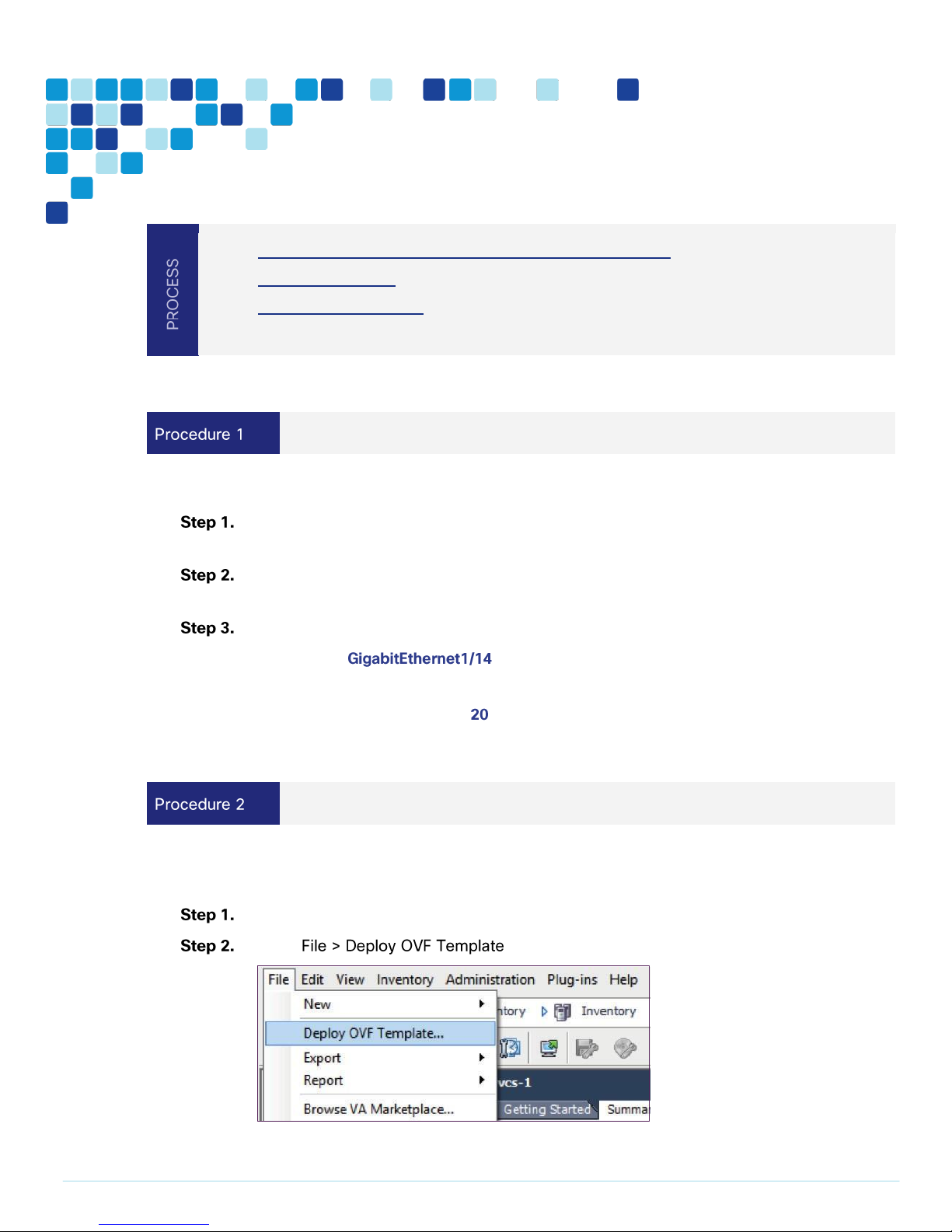
Configure the port as an access port.
interface
description BE6000
switchport access vlan
switchport host
This procedure represents a typical installation. The Deploy OVF Template wizard dynamically changes to
reflect host configuration so your steps may vary.
Log in to vSphere in order to access the ESXi Host.
Select .
Page 16
Deployment Details
PAGE 16
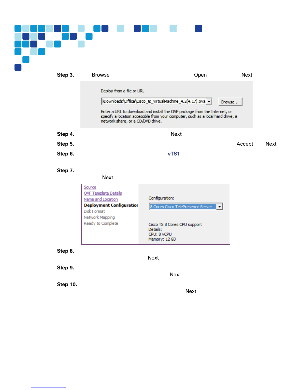
Click , find the location of the .ova file, click , and then click .
On the OVF Template Details page, click .
If an End User License Agreement page appears, read the EULA, click then .
On the Name and Location page, enter and the Inventory Location where the virtual
machine will reside.
On the Deployment Configuration page, select 8 Cores Cisco TelePresence Server and
then click .
If the Host Cluster page comes, select the host or cluster you want to run the deployed
virtual machine, and then click .
If the Resource Pool page comes, select the resource pool with which you want to run the
deployed virtual machine, and then click .
If the Storage page comes, select the datastore onto which the TelePresence Server Virtual
Machine Guest will be deployed, and then click .
Page 17
Deployment Details
PAGE 17
i
Tech Tip
Because VM performance may degrade during the resizing of a partition, Thin Provision is not
recommended.
Configure the VM guest
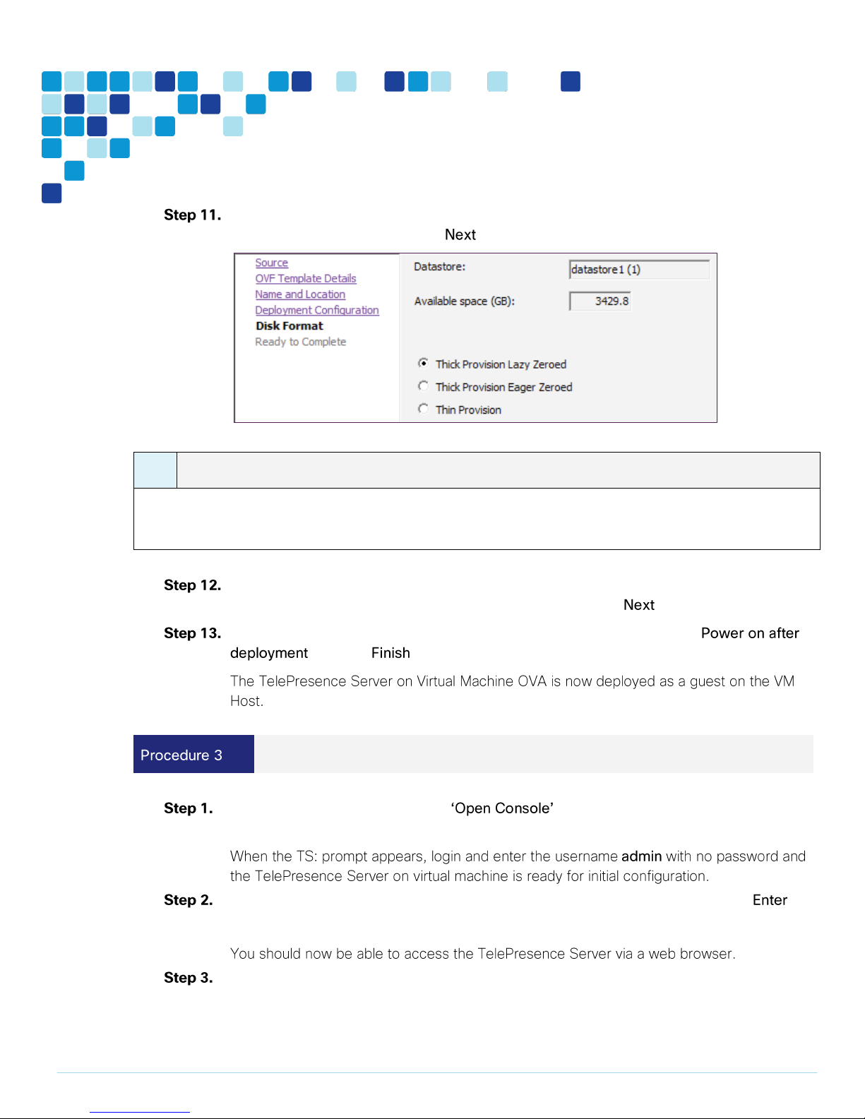
On the Disk Format page, ensure that the default disk format of Thick Provision Lazy
Zeroed is selected and then click .
If Network Mapping is listed, configure it and select the network mapping that applies to
your infrastructure (the default is VM Network), and then click .
On the Ready to Complete page, confirm your deployment Setting, select
and click .
Right-click the VM guest and click . The VM guest will take some time to
boot.
Configure a static IP address following the format shown in the console and press .
static 10.106.170.169 255.255.255.128 10.106.170.129
Use your browser to navigate to the IP address or host name of the device.
Page 18
Deployment Details
PAGE 18
i
Tech Tip
The Cisco TelePresence Server on Virtual Machine application must be managed through the Cisco
TelePresence Conductor XC4.0 (or later), or a similar system, or through the TelePresence Server API.
For more information about the TelePresence Server API, refer to the latest Cisco TelePresence Server
API Reference Guide.
i
Tech Tip
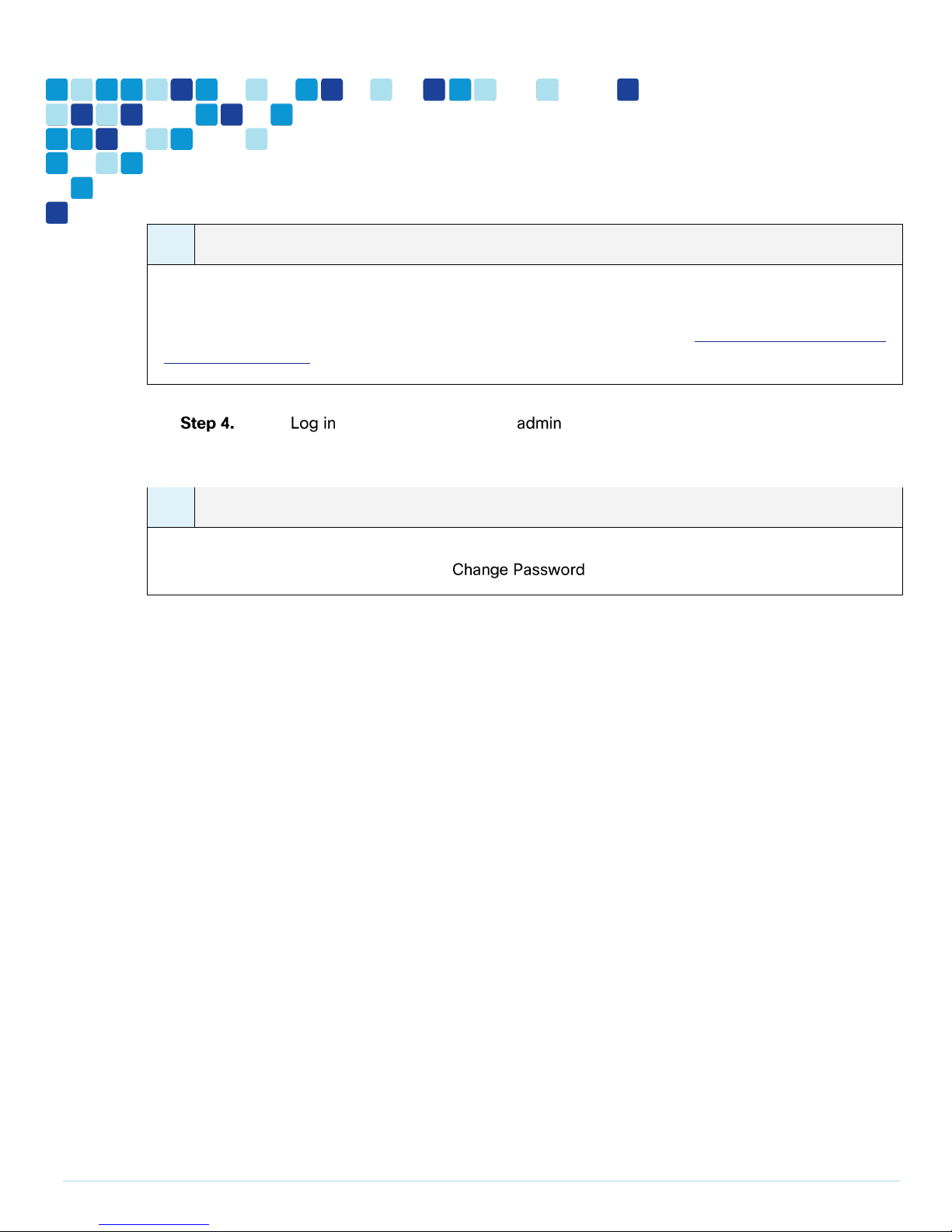
Cisco recommends that you change the admin account to use a password as soon as possible. To do
that, on the Login information page, click .
Click and enter the user name with no password. The Login information page
appears.
Page 19
Deployment Details
PAGE 19
Easy Access Configuration Sheet
1.
Deploy OVA to host
2. Configure the VM guest
3. Apply licenses on TelePresence Conductor
Page 20
Deployment Details
PAGE 20
Deploy OVA to host
i
Tech Tip
If the .ova file is already preloaded onto the datastore, you may have to re-enter
username and password credentials so that vSphere client can access the web server.
i
Tech Tip
Because VM performance may degrade during the resizing of a partition, Thin Provision is not
recommended.
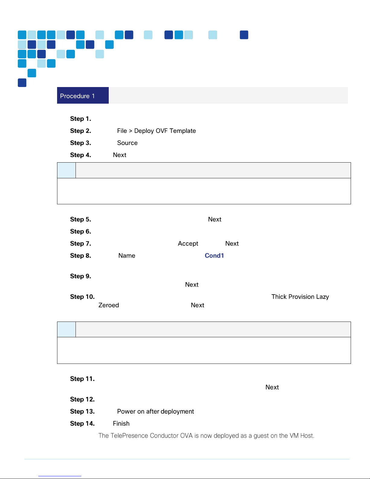
Log in to vSphere to access the ESXi Host.
Select .
Select and browse to the location of the .ova file.
Click .
On the OVF Template Details page click .
On the End User License Agreement page read the EULA.
If you accept the EULA, click and then .
On the and Location page enter as the Name for this TelePresence
Conductor VM guest.
On the Storage page, select the datastore onto which TelePresence Conductor VM Guest
will be deployed, and then click .
On the Disk Format page, ensure that the default disk format of
is selected and then click .
If Network Mapping is listed, configure it and select the network mapping that applies to
your infrastructure (the default is VM network), and then click .
On the Ready to Complete page, confirm your deployment settings.
Select .
Click .
Page 21
Deployment Details
PAGE 21
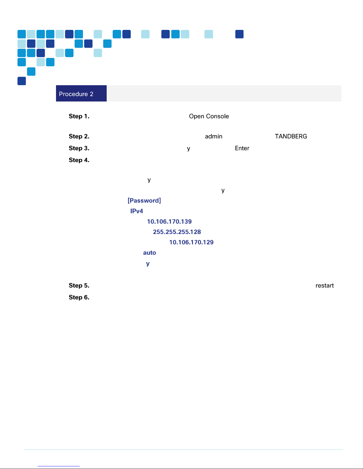
Configure the VM guest
Right-click the VM guest and click . The VM guest will take some time to
boot.
At the login prompt, enter the username , and the password .
At the Install Wizard prompt, type , and then press .
To enter IP information, follow the Install Wizard. Enter the following in the relevant fields.
Configure other entries as required.
Run Install wizard:
Do you wish to change the system password:
Password:
IP Protocol:
IP Address LAN1:
Subnet Mask LAN1:
Default Gateway Address:
Ethernet Speed:
Run ssh daemon:
The configuration is applied and TelePresence Conductor logs you out.
Log into TelePresence Conductor as root and then restart the VM guest by typing .
You should now be able to access TelePresence Conductor via a web browser.
Page 22
Deployment Details
PAGE 22
Apply licenses on TelePresence Conductor
i
Tech Tip
For additional licensing details, refer the Cisco Preferred Architecture for Midmarket Collaboration,
Design Overview.
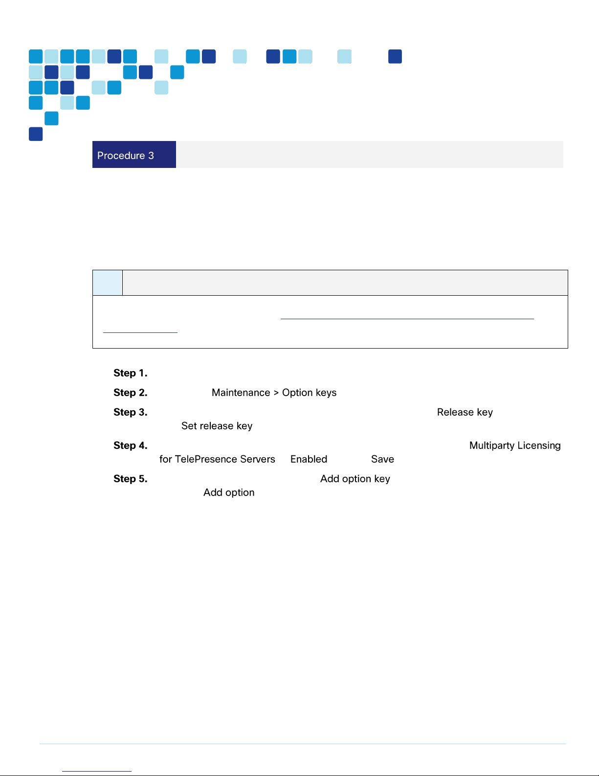
For the scenarios covered in this CVD, following are the type of licenses installed on the TelePresence
Conductor:
Release Key
Personal Multiparty License
In your browser, enter the correct IP address and log in as admin.
Navigate to .
On the Option Keys page enter the release key provided in the field and then
click .
On the Options Keys page, under Multiparty Licensing section, set the
as and click .
For each option key provided, in the field, enter the option key value and
then click .
Page 23
Deployment Details
PAGE 23
Easy Access Configuration Sheet
1. Install Windows Server
2. Install TMS on the Windows Server
3. Install TMSPE on the Windows Server
i
Tech Tip
The SQL Server can also be installed off-box for resiliency.
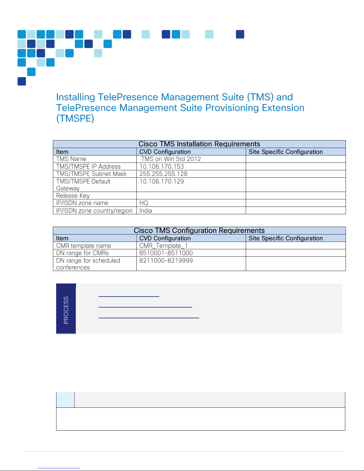
Installing TMS involves installation of two applications, TMS Core and the TMSPE. Both applications are
installed on Windows Server, which is installed as a VM on the BE6000.
This CVD installs the TMS applications on Windows Server 2012 Standard 64 bit Edition with Microsoft
SQL Server 2012 64 bit installed on it. TMS stores all its customer data in its SQL database.
Page 24
Deployment Details
PAGE 24
Install Windows Server
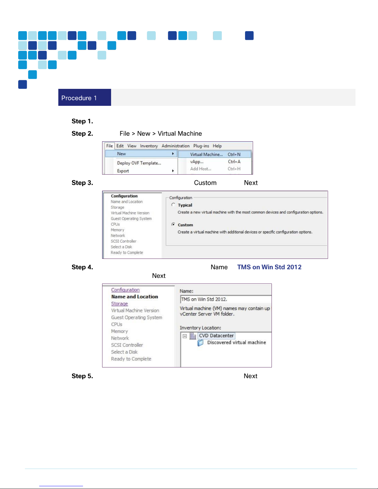
Log in to vSphere to access the ESXi Host.
Select .
On the Configuration page select and click .
On the Name and Location page, enter as , select Inventory
Location and click .
On the Storage page select the datastore and click .
Page 25
Deployment Details
PAGE 25
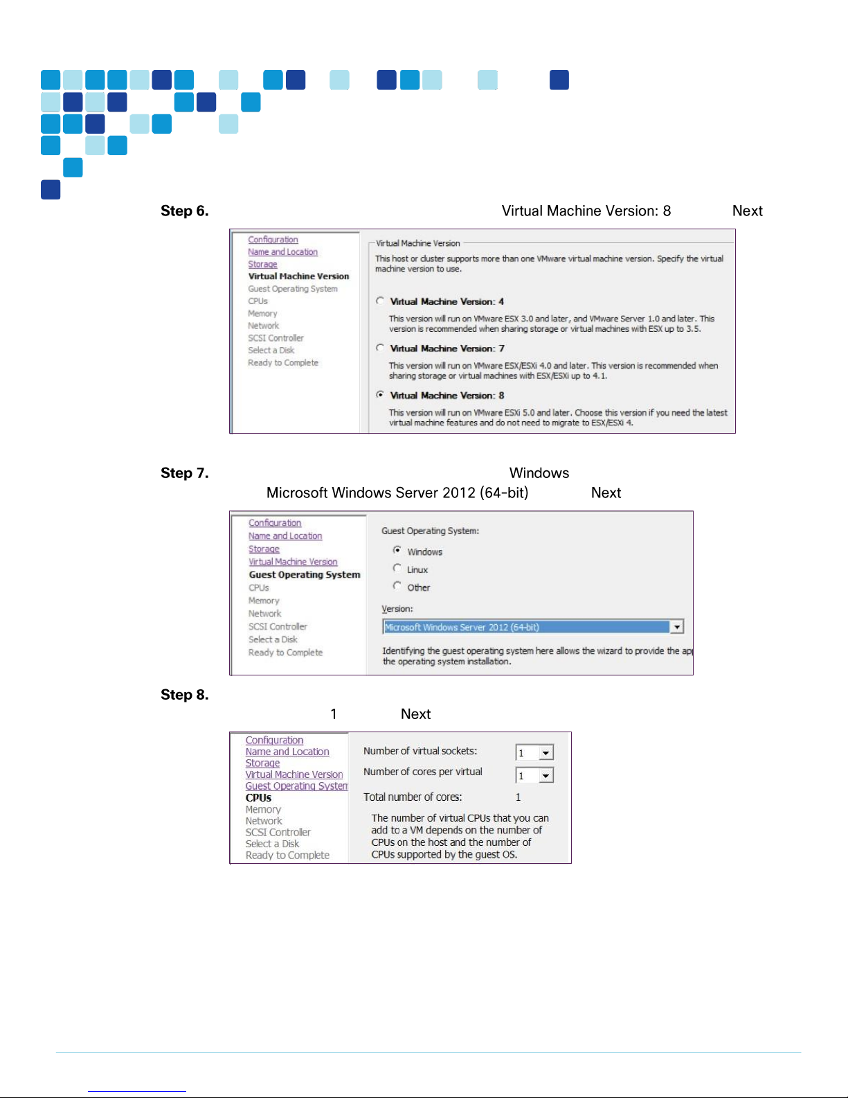
On the Virtual Machine Version page, select and click .
On the Guest Operating System page, select under Guest Operating System,
select and click .
On the CPUs page, select Number of Virtual sockets as 1, select Number of cores per
virtual socket as and click .
Page 26
Deployment Details
PAGE 26
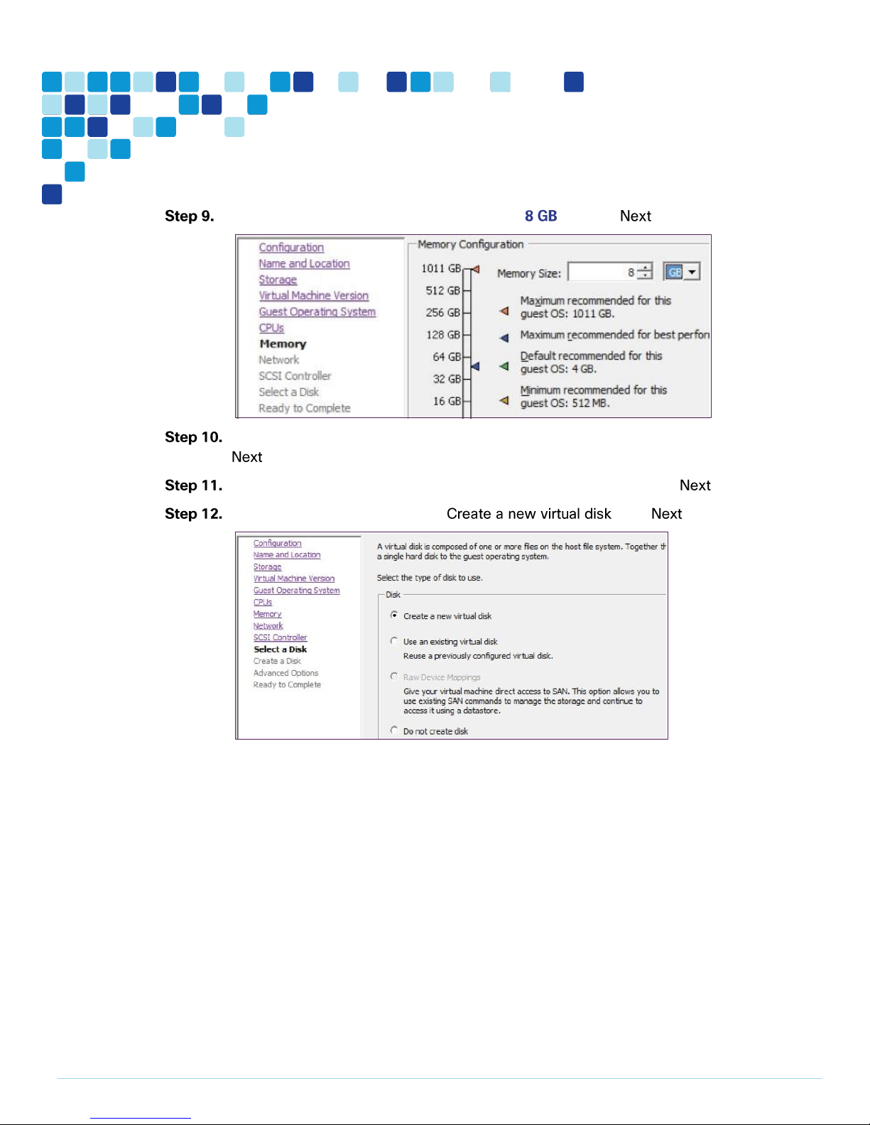
On the Memory page, select Memory Size as and click .
On the Network page, select the How many NICs do you want to connect as 1 and click
.
On the SCSI Controller page, select the appropriate settings and click .
On the Select a disk page, select , click .
Page 27
Deployment Details
PAGE 27
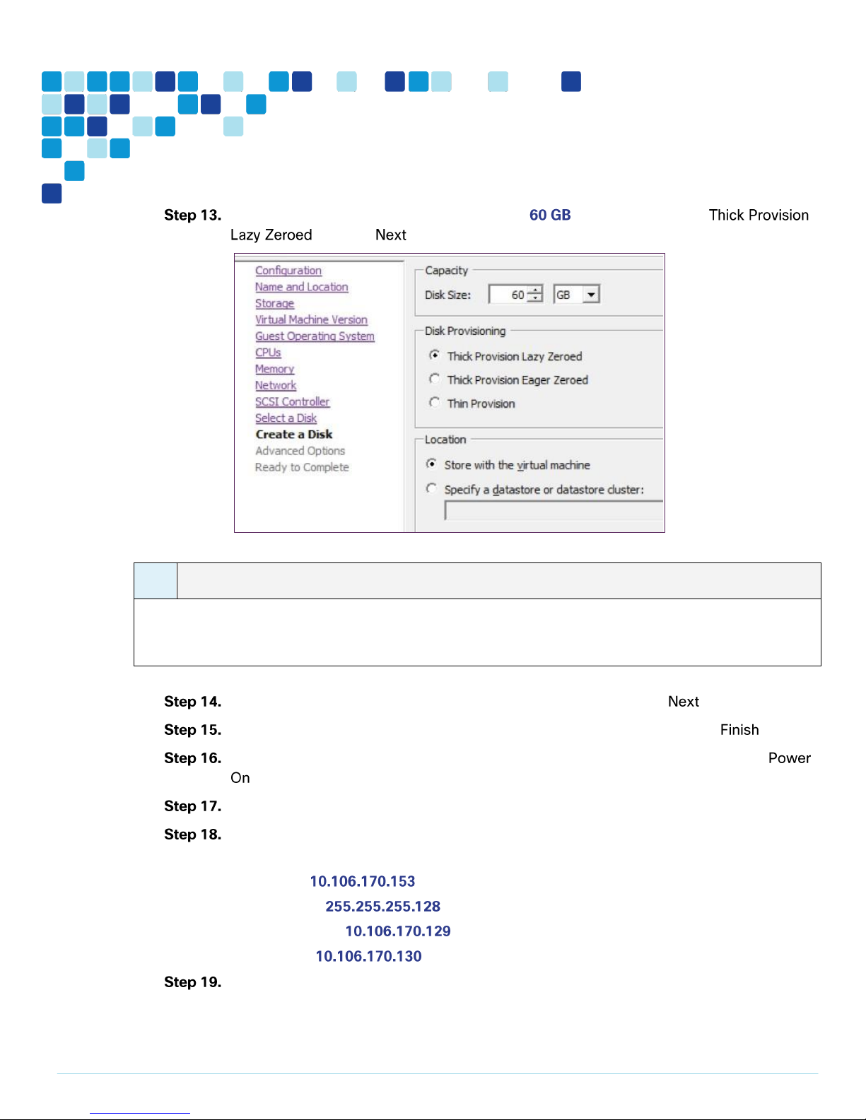
On the Create a Disk page, select Disk Size as , Disk Provisioning as
i
Tech Tip
Because VM performance may degrade during the resizing of a partition, Thin provision is not
recommended.
and click .
On the Advanced Options page, select appropriate options and click .
On the Ready to Complete page, confirm your deployment settings and click .
Once the VM is created, right click on the newly created VM, select Power and click
.
Install Windows Server 2012 Standard on this newly created VM.
To configure the IP information, enter the following in the relevant fields. Configure other
entries as required.
IP address—
Subnet mask—
Default gateway—
DNS server—
Complete all critical windows update, close all open applications and disable virus-scanning
software and other software that may prevent an installation from completing.
Page 28
Deployment Details
PAGE 28
i
Tech Tip
Depending on windows components needing to be added, you may me prompted to reboot the server
more than once during the installation. The installer automatically resumes after the server boots.
Install TMS on the Windows Server
i
Tech Tip
For additional licensing details, refer the Cisco Preferred Architecture for Midmarket Collaboration,
Design Overview.
Install SQL Server 2012 on the Windows Server.
For the scenarios covered in this CVD, following are the type of licenses installed on the TMS:
Release Key
Download the Cisco TMS. zip file from cisco.com.
Extract the .zip file.
Run the Cisco TMS executable as administrator.
Click to continue.
Page 29
Deployment Details
PAGE 29
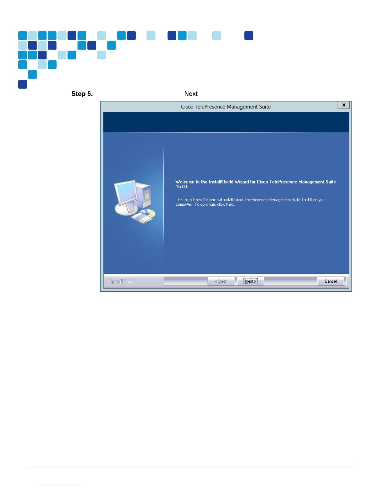
On the welcome screen, click .
Page 30
Deployment Details
PAGE 30
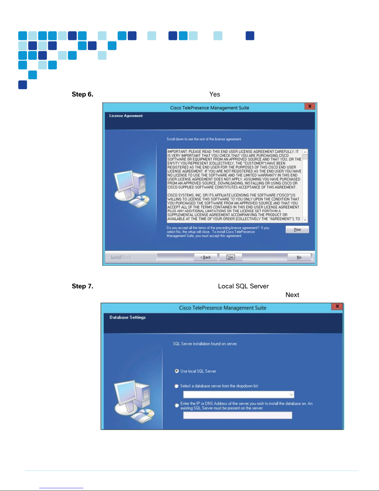
On the License Agreement page, click .
On the database setting page, select Use , enter the username,
password to allow the installer to create a new database and click .
Page 31

Deployment Details
PAGE 31
i
Tech Tip
The SQL Server can also be installed off-box for resiliency.
On and page, enter the release key and click .
Page 32

Deployment Details
PAGE 32
On the and page, enter the following:
TMS Server IPv4 Address—
IP Broadcast/Multicast Addresses for system discovery—
Click .
On the Zone page, enter the following:
Name—
Country/Region—
Click .
On the page, specify the TMS installation path and click .
Page 33

Deployment Details
PAGE 33
On the page, click to generate the new encryption key and click
.
Click .
On the page, verify all the settings.
Click .
On the page, click to generate a self-signed
certificate and click ok.
Page 34

Deployment Details
PAGE 34
Click .
Install TMSPE on the Windows Server
The setup wizard is complete.
Complete all critical windows update, close all open applications and disable virus-scanning
software and other software that may prevent an installation from completing.
Make sure that SQL browser service is running and java version 7 is installed (java version
8 is not supported).
Extract the TMSPE installer from the zip archive to the TMS server.
Page 35

Deployment Details
PAGE 35
Run the TMSPE installer as .
Click .
On the page, select the
checkbox and click .
Page 36

Deployment Details
PAGE 36
On the page, click on the component icons and select the
for all the components and click .
On the page, enter the TMS Admin credentials and click .
Page 37

Deployment Details
PAGE 37
On the page, enter the SQL Server information and click .
On page, click .
After the installation is done, click on the button to complete the setup wizard.
The setup wizard is complete.
Page 38

Deployment Details
PAGE 38
i
Tech Tip
Please refer the latest “Cisco TelePresence Management Suite Installation and Upgrade Guide” for
more installation guidelines.
1. Deploy OVA to host (recording only)
2. Install Windows Server 2008 Standard R2 SP1 (recording only)
3. Install IIS on the Windows Server (recording only)
4. Install Window Media Services on the Windows Server (recording only)
5. Install Windows Server Features on the Windows Server (recording only)
6. Install TCS on the Windows Server (recording only)
Deploy OVA to host (recording only)
Easy Access Configuration Sheet
Log in to vSphere to access the ESXi Host.
Select .
Select and browse to the location of the .ova file.
Page 39

Deployment Details
PAGE 39
i
Tech Tip
Because VM performance may degrade during the resizing of a partition, Thin Provision is not
recommended.
Install Windows Server 2008 Standard R2 SP1 (recording only)
Click .
On the OVF Template Details page click .
On the and Location page enter as the Name for this TelePresence Content
Server VM guest.
On the Disk Format page, ensure that the default disk format of
is selected and then click .
On the Ready to Complete page, confirm your deployment settings, select
and click .
The TelePresence Content Server OVA is now deployed as a guest on the VM Host.
Install Windows Server 2008 Standard R2 Service Pack 1 in the new VM created in the
previous procedure.
Create two partitions on the host while installing Windows:
C: for program files with a minimum of 100 GB space
E: for media files with the remainder of available space
Follow the prompts to complete the Windows Server installation.
Install VMware Tools.
To configure the IP information, enter the following in the relevant fields:
IP address –
Subnet mask –
Default gateway –
DNS server –
Complete all critical windows update, close all open applications and disable virus-scanning
software and other software that may prevent an installation from completing.
Page 40

Deployment Details
PAGE 40
i
Tech Tip
Depending on windows components needing to be added, you may me prompted to reboot the server
more than once during the installation. The installer automatically resumes after the server boots.
Install IIS on the Windows Server (recording only)
Install Window Media Services on the Windows Server (recording only)
Windows is installed.
On the VM host, navigate to . Click the Web Server
(IIS) check box and click .
In the Select Role Services window, select all the roles services. Click .
Click Install to complete the IIS installation.
Download Windows Media Services (WMS) from http://www.microsoft.com.
Install the update.
Navigate to . Select the Streaming Media Services
check box and click .
In the Select Role Services window, select the three Role Services check boxes and click
. A pop-up window appears for installing the dependent services. Click to install
the dependent services.
In the Data Transfer Protocols window, select the Real Time Streaming Protocol (RTSP)
check box and click .
Click to complete the WMS installation.
Windows Media Services are Installed.
Page 41

Deployment Details
PAGE 41
Install Windows Server Features on the Windows Server (recording only)
Install TCS on the Windows Server (recording only)
Navigate to .
In the Select Features window, select the ,
, and Tools check boxes and click .
Click Install to install the Backup Features.
Navigate to .
In the Select Features window, click the check box and click .
Click Install to install the Desktop Experience.
A pop-up appears for installing the dependent services. Click to install the dependent
services.
Click to restart the system.
Windows server features are installed.
Run dotNetFx40_Full_x86_x64.exe package to install .NET.
Launch the command prompt and run as an administrator. Go to the location, where the
TCS_6.2_BE6K_Package.zip is extracted.
Run GetTCSVirtualSN.exe to generate the virtual serial number (vSN) for your Content Server VM.
Copy the virtual serial number.
In the TCS_6.2_BE6K_Package.zip extracted directory, create a TCSLic.txt file by using the
licensing information in this format:
Page 42

Deployment Details
PAGE 42
i
Tech Tip
In the license text file, make sure that there are no extra spaces before or after the license keys.
In the command prompt, run the from the extracted
TCS_6.2_BE6K_Package.zip directory to configure the Content Server Pre-Installer.
Run to install the VM Content Server software on the appliance. Follow the
prompts to complete the TCS installation.
Run the from the VM Scripts folder in the command prompt to configure
the Post-Installer. This will reboot the system.
Cisco TelePresence Content Server is installed.
Page 43

Deployment Details
PAGE 43
1. Create a user for Conductor
2. Create a user for TMS
3. Configure SIP
Create a user for Conductor
For TelePresence Conductor to communicate with the TelePresence Server, it must use credentials for a
user account that has administrator rights. We recommend that you create a dedicated administrator-level
user for this task.
On the web interface of the virtual TelePresence Server you want to configure, log in as an
administrator.
Navigate to .
Enter the following in the relevant fields, configure other entries as required:
User ID—
Name—
Access rights—
Click .
Enable HTTPS by going to and enter the following value:
HTTPS checked—
Click .
Page 44

Deployment Details
PAGE 44
Create a user for TMS
For TMS to communicate with the TelePresence Server, it must use credentials for a user account that has
administrator rights. We recommend that you create a dedicated administrator-level user for this task.
On the web interface of the virtual TelePresence Server you want to configure, log in as an
administrator.
Navigate to .
Enter the following in the relevant fields, configure other entries as required:
User ID—
Name—
Access rights—
Click .
Page 45

Deployment Details
PAGE 45
Configure SIP
The TelePresence Server needs the ability to dial out to devices, for example, when an auto-dialed
participant is associated with a template in TelePresence Conductor. To do this, the TelePresence Server
needs to know where to direct signaling requests.
Go to .
Enter the following values into the relevant fields:
Outbound call configuration—
Outbound address—Leave Blank
Outbound domain—Leave Blank
Username—
Password—
Outbound Transport—
Advertise Dual IPv4/IPv6—
Negotiate SRTP using SDES—
Click
Page 46

Deployment Details
PAGE 46
1. Create a user for Unified CM access
2. Create a user for TMS CMR access
3.
Create a user for TMS-scheduled conference access
4. Change the system settings
5. Add IP addresses for instant, personal and scheduled CMR conference locations on
Conductor
6. Create Service preferences
7. Set up conference bridge pools
8. Add Conference Bridge Pool in Service preference
9. Create a conference template for an instant CMR conference
10. Create a conference template for personal CMR conferences
11. Create a conference template for scheduled CMR conference
12. Create a conference alias for an personal CMR conferences
13. Create a conference alias for an scheduled CMR conference
14. Create locations in Conductor
15. Add locations to conference bridge pools
Create a user for Unified CM access
For Unified CM to communicate with TelePresence Conductor, you must configure a user with
administrator rights on TelePresence Conductor. We recommend that you create a dedicated Read-write
user for this task.
Log into TelePresence Conductor as a user with administrator rights.
Go to accounts.
Click .
Enter the following in the relevant fields:
Name—
Access level—
Password—
Page 47

Deployment Details
PAGE 47
Create a user for TMS CMR access
Web access—
API access—
State—
Click .
For TMS to communicate with TelePresence Conductor, you must configure a user with administrator
rights on TelePresence Conductor. We recommend that you create a dedicated Read-write user for this
task.
Log into TelePresence Conductor as a user with administrator rights.
Go to
Click .
Page 48

Deployment Details
PAGE 48
Enter the following in the relevant fields:
Create a user for TMS-scheduled conference access
Name—
Access level—
Password—
Web access—
State—
Click .
Log into TelePresence Conductor as a user with administrator rights.
Go to accounts.
Click .
Page 49

Deployment Details
PAGE 49
Enter the following in the relevant fields:
Change the system settings
i
Tech Tip
The FQDN of TelePresence Conductor will be
Name—
Access level—
Password—
Web access—
API access—
State—
Click .
Navigate to and enter the following values into the relevant fields:
System host name—
Domain name—
Address 1—
Page 50

Deployment Details
PAGE 50
Click .
Navigate to and set to .
Page 51

Deployment Details
PAGE 51
Add IP addresses for instant, personal and scheduled CMR conference locations
on Conductor
i
Tech Tip
These IP addresses must be on the same subnet as the primary TelePresence Conductor IP interface,
and they must be reserved for use by this TelePresence Conductor alone.
Ensure that under the Status section, the State is . Synchronization can take a
couple of minutes.
In , in the Additional addresses for LAN 1 section click
.
Add the IP addresses used for instant CMRs ( ) and click .
Add the IP addresses used for personal and scheduled CMR conferences
( ) and click .
Page 52

Deployment Details
PAGE 52
In the Additional addresses for LAN 1 list, verify that the IP addresses were added
Create Service preferences
correctly.
Navigate to options and click . Your network interface
changes are applied.
Wait for TelePresence Conductor to restart and then verify that the new TelePresence
Conductor IP address is active on the network by pinging the IP address from another
device.
Go to .
Click .
Page 53

Deployment Details
PAGE 53
Enter the following values into the relevant fields:
Set up conference bridge pools
Service Preference name—
Conference bridge type—
Click .
To set up a conference bridge pool, you need to create a conference bridge pool and then add the
TelePresence Server to it.
Navigate to pools and click .
Enter the following values into the relevant fields, leaving the other fields at their default
values:
Pool name—
Conference bridge type—
Click .
On the Conference bridge pools page, click .
Page 54

Deployment Details
PAGE 54
Enter the following values into the relevant fields, leaving the other fields at their default
values:
Name—
State—
IP address of FQDN—
Protocol –
Port—
Conference bridge username—
Conference bridge password—
SIP port—
Click .
Ensure that under the section, in the Status column, the
conference bridge is listed as .
Page 55

Deployment Details
PAGE 55
Add Conference Bridge Pool in Service preference
Go to .
Click .
Select under the Pools section.
Click .
Check the radio button stating .
Click .
Page 56

Deployment Details
PAGE 56
Create a conference template for an instant CMR conference
Navigate to templates and click .
Enter the following into the relevant fields, leaving other fields at their default values:
Name—
Conference type—
Service preference—
Participant quality—
Optimize resources—
Content quality—
Configure other entries as required.
Click .
Page 57

Deployment Details
PAGE 57
Create a conference template for personal CMR conferences
Navigate to templates and click .
Enter the following into the relevant fields, leaving other fields at their default values:
Name—
Conference type—
Service preference—
Participant quality—
Optimize resources—
Content quality—
Configure other entries as required.
Click .
Page 58

Deployment Details
PAGE 58
Create a conference template for scheduled CMR conference
Navigate to templates and click .
Enter the following into the relevant fields, leaving other fields at their default values:
Name—
Conference type—
Service preference—
Participant quality—
Optimize resources—
Content quality—
Scheduled Conference—
Configure other entries as required.
Click .
Page 59

Deployment Details
PAGE 59
Create a conference alias for an personal CMR conferences
Navigate to and click .
Enter the following into the relevant fields, leaving other fields at their default values:
Name—
Incoming Alias (must use regex)—
Conference name—
Priority—
Conference template—
Role type—
Allow conference to be created—
Click .
Page 60

Deployment Details
PAGE 60
Create a conference alias for an scheduled CMR conference
Navigate to and click .
Enter the following into the relevant fields, leaving other fields at their default values:
Name—
Incoming Alias (must use regex)—
Conference name—
Priority—
Conference template—
Role type—
Allow conference to be created—
Click .
Page 61

Deployment Details
PAGE 61
Create locations in Conductor
Navigate to and click .
Enter the following into the relevant fields, leaving other fields at their default values:
Location name—
Conference type—
Ad hoc IP address (local)—
Template—
Rendezvous IP address (local)—
Trunk IP address—
Trunk port—
Trunk transport protocol—
Page 62

Deployment Details
PAGE 62
Click .
Page 63

Deployment Details
PAGE 63
Add locations to conference bridge pools
i
Tech Tip
For TelePresence Conductor redundancy, please refer the latest Cisco TelePresence Conductor
Clustering with Cisco Unified Communications Manager Deployment Guide.
Log into TelePresence Conductor as a user with administrator rights.
Navigate to , and click .
Select the Location as .
Click on .
Page 64

Deployment Details
PAGE 64
1. Enable TMSPE on TMS
2. Setup users on TMS
3. Add Conductor for CMR on TMS
4. Setup CMRs on TMS
5. Add Conductor for scheduling on TMS
6. Add TelePresence Server for scheduling on TMS
7. Create conference alias on TMS
8. Configure conference settings on TMS
Enable TMSPE on TMS
Log into TMS as a user with administrator rights.
Navigate to and set the
Click on .
field as .
Page 65

Deployment Details
PAGE 65
Setup users on TMS
Navigate to .
Click on and then click on .
Enter as when the dialog comes up and
click .
Click on .
Page 66

Deployment Details
PAGE 66
Enter the following into the relevant fields, leaving other fields at their default values:
Display Name—
Username—
Password—
Email—
Last Name—
Click .
Page 67

Deployment Details
PAGE 67
Add Conductor for CMR on TMS
Navigate to .
Under , click .
Click and enter the following into the relevant fields, leaving other fields at their
default values:
Hostname/IP—
Name—
Port—
Username—
Password—
Domain—
Click .
Page 68

Deployment Details
PAGE 68
Setup CMRs on TMS
Navigate to Systems > Provisioning > Users and click on Video_Users (Local).
Under Collaboration Meeting Room Templates, click New Template.
Enter the following into the relevant fields, leaving the other fields at their default values:
Template Name—
TelePresence Conductor—
Service Preference—
Multiparty License Mode –
SIP Alias Pattern—
Numeric Alias Pattern—
Type—
Number Ranges—
Maximum Conference Quality—
Content Sharing—
Maximum Content Quality—
Optimize Resources—
Page 69

Deployment Details
PAGE 69
Click .
Page 70

Deployment Details
PAGE 70
Select the radio button for under the
Add Conductor for scheduling on TMS
Templates and click .
The CMR template is applied to all the users in group.
Navigate to .
Click on on the left folder view and then click on on the
right Discovered Systems section.
Page 71

Deployment Details
PAGE 71
Enter the following into the relevant fields:
Specify Systems by IP Addresses or DNS Names—
ISDN Zones—
IP Zones—
Time Zones—
Usernames—
Passwords—
Persistent Template—
Usage Type—
Click .
Click .
Page 72

Deployment Details
PAGE 72
Add TelePresence Server for scheduling on TMS
Navigate to .
Click on on the left folder view and then click on on the
right Discovered Systems section.
Enter the following into the relevant fields:
Specify Systems by IP Addresses or DNS Names—
ISDN Zone—
IP Zone—
Time Zone—
Username—
Password—
Persistent Template—
Usage Type—
Click .
Click .
Page 73

Deployment Details
PAGE 73
Create conference alias on TMS
Navigate to .
Click on under Discovered Systems and then click
tab.
Click .
Enter the following into the relevant fields:
Name—
Alias Pattern—
Priority—
Prefer for Multiscreen—
Allow Booking—
Click .
Page 74

Deployment Details
PAGE 74
Configure conference settings on TMS
Navigate to .
Click on under Discovered Systems and then click
tab.
Enter the following into the relevant fields:
Numeric ID Base—
Numeric ID Step—
Click .
Navigate to .
Enter .
Click .
Page 75

Deployment Details
PAGE 75
Easy Access Configuration Sheet
1. Configure region for video
2. Configure device pool for video and add the video region
3. Configure Unified CM trunk to TelePresence Conductor for personal and scheduled CMR
conferences
4. Configure Unified CM trunk to Conductor for instant CMR conferences
5. Configure SIP Trunk Security Profile for TCS (recording only)
6. Configure SIP Profile for TCS (recording only)
7. Configure Unified CM directory number route pattern for personal and scheduled CMR
conferences
8. Configure Unified CM directory number route pattern for TCS (recording only)
9. Configure Unified CM SIP route pattern for personal CMR conferences
10. Configure Conductor as conference bridge
11. Configure MRG and MRGL for video and add Conductor to this MRG
12. Add this MRGL to the device profile for video
Page 76

Deployment Details
PAGE 76
Configure region for video
Configure device pool for video and add the video region
Navigate to , and click in order to create
a new Region.
In , enter , and then click .
Under , select .
Under , enter kbps.
This CVD is using 32256 as the configured video bandwidth for this region.
Click .
Navigate to , and then click in order to add a new device
pool.
Enter the following into the relevant fields, leaving the other fields at their default values:
Device Pool Name—
Cisco Unified Communications Manager Group –
Date/Time Group –
Region—
Page 77

Deployment Details
PAGE 77
Click .
Page 78

Deployment Details
PAGE 78
Configure Unified CM trunk to TelePresence Conductor for personal and
scheduled CMR conferences
A trunk is a communications channel on Unified CM that enables it to connect to other servers. Using one
or more trunks, Unified CM can receive or place voice, video, and encrypted calls, exchange real-time
event information, and communicate in other ways with call control servers and other external servers.
Navigate to , and then click in order to create a new SIP trunk.
Enter the following into the relevant fields:
Trunk Type—
Device Protocol—
Trunk Service Type—
Click .
Enter the following into the relevant fields, leaving other fields at their default values:
Device Name—
Device Pool—
Destination Address—
Destination Port—
SIP Trunk Security Profile—
SIP Profile—
Normalization Script—
Page 79

Deployment Details
PAGE 79
Configure Unified CM trunk to Conductor for instant CMR conferences
Click .
Click .
Navigate to , and then click in order to create a new SIP trunk.
Enter the following into the relevant fields:
Trunk Type—
Device Protocol—
Trunk Service Type—
Click .
Page 80

Deployment Details
PAGE 80
Enter the following into the relevant fields, leaving other fields at their default values:
Device Name—
Device Pool—
Destination Address—
Destination Port—
SIP Trunk Security Profile—
SIP Profile—
Normalization Script—
Click .
Click .
Page 81

Deployment Details
PAGE 81
Configure SIP Trunk Security Profile for TCS (recording only)
Navigate to , and then click .
Enter the following into the relevant fields, leaving other fields at their default values:
Name -
Accept out-of-dialog refer –
Accept unsolicited notification –
Accept replaces header –
Click .
Page 82

Deployment Details
PAGE 82
Configure SIP Profile for TCS (recording only)
Configure Unified CM directory number route pattern for personal and scheduled
CMR conferences
Navigate to , and then click
Click on the icon on the right side of .
Enter the following into the relevant fields, leaving other fields at their default values:
Name -
Early Offer support for voice and video calls –
Send send-receive SDP in mid-call INVITE –
Allow Presentation Sharing using BFCP –
Click .
This procedure describes configuring the Unified CM route pattern to match the SIP trunk to TelePresence
Conductor for personal and scheduled CMR conferences.
Navigate to , and then click in order
to create a new route pattern.
Enter the following into the relevant fields, leaving other fields at their default values:
Route Pattern—
Gateway/Route List—
Page 83

Deployment Details
PAGE 83
Configure Unified CM directory number route pattern for TCS (recording only)
Click .
Navigate to , and then click in order
to create a new route pattern.
Enter the following into the relevant fields, leaving other fields at their default values:
Route Pattern—
Gateway/Route List—
Click .
Page 84

Deployment Details
PAGE 84
Configure Unified CM SIP route pattern for personal CMR conferences
The regular Unified CM SIP route pattern routing cannot be used for routing calls to the personal CMR
conferences created in this document because Unified CM can route URIs only based on domains (e.g.
cisco.local) and not the URIs created for the personal CMR conferences (e.g.
cmr@mmcvd.ciscolabs.com).
To route the calls to the personal CMR conference URIs we have to use the ILS (Intercluster Lookup
Service) service in the Unified CM and manually import the personal CMR conference URIs into the Unified
CM.
Following steps will configure the Unified CM to enable ILS and import the permpersonal CMR conference
URLs.
Click the tab on the top right corner of the page,
select from the dropdown list and click .
Navigate to .
Page 85

Deployment Details
PAGE 85
Select from the dropdown list under and click
.
Select the under the and
click .
Go back to page by clicking on the tab on
top right corner of the page, selecting the
and then clicking .
Page 86

Deployment Details
PAGE 86
Navigate to and select as the
i
Tech Tip
The Route String is just a name, it does not represent that the user will have to dial
*cmr.mmcvd.ciscolabs.com.
under the tab.
Navigate to
and click .
Enter the following into the relevant fields:
Name—
Route String—
Click .
Create a in the following format for all the personal CMR conference URIs
that has to be imported into the ILS of the Unified CM.
Navigate to and click .
Enter the following into the relevant fields:
File—
Select The Target—
Select Transaction Type—
Page 87

Deployment Details
PAGE 87
Overwrite File if it exists—
Click .
Navigate to
.
Enter the following into the relevant fields:
File Name—
Imported Global Dial Plan Catalog—
Run Immediately—
Click .
Navigate to .
Click .
Enter the following into the relevant fields, leaving other fields at their default values:
IPv4 Pattern—
SIP Trunk/Route List—
Page 88

Deployment Details
PAGE 88
Configure Conductor as conference bridge
Click .
This procedure describes configuring Conductor as a conference bridge in Unified CM for instant CMR
conferences.
Navigate to , and then click in order to
create a new conference bridge.
Enter the following into the relevant fields, leaving other fields at their default values:
Conference Bridge Type—
Conference Bridge Name—
SIP Trunk—
Allow Conference Bridge Control of the Call Security Icon—
Override SIP Trunk Destination as HTTP Address—
Username—
Password—
HTTP Port—
Page 89

Deployment Details
PAGE 89
Click .
Make sure that the Conference Bridge shows as registered to the Unified CM.
Page 90

Deployment Details
PAGE 90
Configure MRG and MRGL for video and add Conductor to this MRG
Navigate to , and then click .
In , enter .
In , select and click the down arrow to move
it down to the .
Click .
Navigate to , and then click .
In , enter
Page 91

Deployment Details
PAGE 91
In , select and click the down arrow to
Add this MRGL to the device profile for video
move it down to the .
Click .
Navigate to , and then click in order to list all configured Device
Pools.
Select .
In , select .
Click .
Page 92

Deployment Details
PAGE 92
1. Configure Site settings (recording only)
2. Configure Recording Alias (recording only)
Configure Site settings (recording only)
Configure Recording Alias (recording only)
Navigate to .
In SIP settings, enter the following in the relevant fields:
SIP enabled –
SIP display name –
Registration –
Server Address –
Transport
Click .
Navigate to and click .
Enter the following in the relevant fields and leave the other fields at their default values:
Name -
Page 93

Deployment Details
PAGE 93
SIP address (URI) -
Click .
Page 94

Deployment Details
PAGE 94
1. Configure Unified CM for endpoints
2. Configure SX20
Configure Unified CM for endpoints
Navigate to , and then click .
In , select , and then click :
Click .
Enter the following into the relevant field, leaving the other fields at their default values:
MAC Address—
Device Pool—
Phone Button Template—
Common Phone Profile—
Device Security Profile—
SIP Profile—
Page 95

Deployment Details
PAGE 95
Click .
Click .
In , enter , and then click .
Page 96

Deployment Details
PAGE 96
Under , enter as the URI and click .
Page 97

Deployment Details
PAGE 97
Configure SX20
Navigate to
.
In , enter , and then click .
Page 98

Deployment Details
PAGE 98
1. Dial TCS URI (recording only)
Dial TCS URI (recording only)
Dial and wait till the countdown finishes and is 0.
Now the call to the TCS will be recording till the call is put to an end.
Page 99

Deployment Details
PAGE 99
1. Initiate instant CMR conference
2. Create Personal CMR conferences
3. Initiate Personal CMR conference
4. Create scheduled CMR conference
Initiate instant CMR conference
Create Personal CMR conferences
Call from .
After the call is connected, press on the button.
Call from .
Press the button.
Open a browser, type in the
navigation space and click .
Page 100

Deployment Details
PAGE 100
Click on .
Click .
Enter the personal CMR name as and click .
 Loading...