

Page 1

Configuring Data-Link Switching Plus
This chapter describes how to configure data-link switching plus (DLSw+), Cisco’s implementation of
the DLSw standard for Systems Network Architecture (SNA) and NetBIOS de vices. Refer to the DLSw+
Design and Implementation Guide for more complex configuration instructions. For a complete
description of the DLSw+ commands mentioned in this chapter, refer to the “DLSw+ Commands”
chapter of the Cisco IOS Bridging and IBM Networking Command Reference (Volume 1 of 2). To locate
documentation of other commands that appear in this chapter, use the command reference master index
or search online.
This chapter contains the following sections:
• Technology Overview, page 281
• DLSw+ Configuration Task List, page 288
• Verifying DLSw+, page 310
• Monitoring and Maintaining the DLSw+ Network, page 311
• DLSw+ Configuration Examples, page 312
To identify the hardware platform or software image information associated with a feature, use the
Feature Navigator on Cisco.com to search for information about the feature or refer to the software
release notes for a specific release. For more information, see the “Identifying Platform Support for
Cisco IOS Software Features” section on page lv in the “Using Cisco IOS Software” chapter.
Technology Overview
DLSw+ is a method of transporting SNA and Net BIOS. It complies with the DLSw standard documented
in RFC 1795 and the DLSw Version 2 standard. DLSw+ is an alternative to RSRB that addresses several
inherent problems that exist in RSRB, such as:
• SRB hop-count limits (SRB’s limit is seven)
• Broadcast traffic (including SRB explorer frames or NetBIOS name queries)
• Unnecessary traffic (acknowledgments and keepalives)
• Data-link control timeouts
78-11737-02
Cisco IOS Bridging and IBM Networking Configuration Guide
BC-281
Page 2

Technology Overview
DLSw Standard
The DLSw standard, documented in RFC 1795, defines the switch-to-switch protocol between DLSw
routers. The standard also defines a mechanism to terminate data-link control connections locally and
multiplex the traffic from the data-link control connections to a TCP connection. The standard always
calls for the transport protocol to be TCP and always requires that data-link control connections be
locally terminated (the eq uivalent of Cisco’s local acknowledgment option). The standard also requires
that the SRB RIF be terminated at the DLSw router. The standard describes a means for prioritization
and flow control and defines error recovery procedures that ensure data-link control connections are
appropriately disabled if any part of their associated circuits breaks.
The DLSw standard does not specify when to establish TCP connections. The capabilities exchange
allows compliance to the standard, bu t at different levels of support. The standard does not specify how
to cache learned information about MAC addresses, RIFs, or NetBIOS names. It also does not describe
how to track either capable or preferred DLSw partners for either backup or load-balancing purposes.
The standard does not provide the specifics of media conversion, but leaves the details up to the
implementation. It does not define how to map switch congestion to the flow control for data-link
control. Finally, the MIB is documented under a separate RFC.
Configuring Data-Link Switching Plus
DLSw Version 2 Standard
In the Version 1 standard, a network design requires fully meshed connectivity so that all peers were
connect to every other peer. This design creates unnecessary broadcast traffic because an explorer
propagates to every peer for every broadcast.
The Version 2 standard is documented in RFC 2166. It includes RFC 1795 and adds the following
enhancements:
• IP Multicast, page 282
• UDP Unicast, page 283
• Enhanced Peer-on-Demand Routing Feature, page 283
• Expedited TCP Connection, page 283
Users implement DLSw Version 2 for scalability if they are using multivend or DLSw de vices with an IP
multicast network. DLSw Version 2 requires complex planning because it involves configuration
changes across an IP network.
IP Multicast
Multicast service avoids duplication and excessive bandwidth of broadcast traffic because it replicates
and propagates messages to its multicast members only as necessary. It re duces the amount of network
overhead in the following ways:
• A v oids the need to maintain TCP Switch-to-Switch Protocol (SSP) connections between two DLSw
peers when no circuits are available
• Ensures that each broadcast results in only a single explorer over every link
DLSw Version 2 is for customers who run a multicast IP network and do not need the advantages of
border peering.
BC-282
Cisco IOS Bridging and IBM Networking Configuration Guide
78-11737-02
Page 3

Configuring Data-Link Switching Plus
UDP Unicast
DLSw Version 2 uses UDP unicast in response to an IP multicast. When address resolution packets
(CANUREACH_EX, NETBIOS_NQ_ex, NETBIOS_ANQ, and DATAFRAME) are sent to multiple
destinations (IP multicast service), DLSw Version 2 sends the response frames (ICANREACH_ex and
NAME_RECOGNIZED_ex) via UDP unicast.
UDP unicast uses UDP source port 0. Howe ver , some fire wall products treat packets th at use UDP source
port 0 as security violations, discarding the pa ckets and preventing DLSw connections. To avoid this
situation, use one of the following procedures:
• Configure the firewall to allow UDP packets to use UDP source port 0.
• Use the dlsw udp-disable command to disable UDP unicast and send address resolution packets in
the existing TCP session.
Enhanced Peer-on-Demand Routing Feature
DLSw V ersion 2 establishes TCP connections only when necessary and the TCP connections are brought
down when there are no circuits to a DLSw peer for a specified amount of time. This method, known as
peer-on-demand routing, was recently introduced in DLSw Version 2, but has been implemented in Cisco
DLSw+ border peer technology since Cisco IOS Release 10.3.
Technology Overview
Expedited TCP Connection
DLSw Version 2 efficiently establishes TCP connections. Prev iously, DLSw created two unidirectional
TCP connections and then disconnected one after the capabilities exchange took place. With DLSw
Version 2, a single bidirectional TCP connection establishes if the peer is brought up as a result of an IP
multicast/UDP unicast information exchange.
DLSw+ Features
DLSw+ is Cisco’s version of DLSw and it supports several additional features and enhancements.
DLSw+ is a means of transporting SNA and NetBIOS traffic over a campus or WAN. The end systems
can attach to the network over T ok en Ring, Ethernet, Synchronous Data Link Control (SDLC) Protocol,
Qualified Logical Link Control (QLLC), or Fiber Distributed Data Interface (FDDI). See the DLSw+
Design and Implementation Guide Appendix B, “DLSw+ Support Matrix,” for details. DLSw+ switches
between diverse media and locally terminates the data links, keeping acknowl edgments, k eep ali v es, and
polling off the WAN. Local termination of data links also eliminates data-link control timeouts that can
occur during transient network congestion or when rerouting around failed links. Finally, DLSw+
provides a mechanism for dynamically searching a network for SNA or NetBIOS resources and includes
caching algorithms that minimize broadcast traffic.
DLSw+ is fully compatible with any vendor’ s RFC 1795 implementation and the following features are
available when both peers are using DLSw+:
• Peer groups and border peers
• Backup peers
78-11737-02
• Promiscuous and on-demand peers
• Explorer firewalls and location learning
• NetBIOS dial-on-demand routing feature support
Cisco IOS Bridging and IBM Networking Configuration Guide
BC-283
Page 4

Technology Overview
Configuring Data-Link Switching Plus
• UDP unicast support
• Load balancing
• Support for LLC1 circuits
• Support for multiple bridge groups
• Support for RIF Passthrough
• SNA type of service feature support
• Local acknowledgment for Ethernet-attached devices and media conversion for SNA PU 2.1 and
PU 2.0 devices
• Conversion between LLC2 to SDLC between PU 4 devices
• Local or remote media conversion between LANs and either SDLC Protocol or QLLC
• SNA View, Blue Maps, and Internetwork Status Monitor (ISM) support
MIB enhancements that allow DLSw+ features to be managed by the CiscoWorks Blue products, SNA
Maps, and SNA V ie w. Also, new traps alert network management stations of peer or circuit failures. For
more information, refer to the current Cisco IOS release note for the location of the Cisco MIB website.
Local Acknowledgment
When you have LANs separated by wide geographic distances, and you want to avoid sending data
multiple times, and the loss of user sessions that can occur with time delays, encapsulate the source-route
bridged traffic inside IP datagrams passed over a TCP connection between two routers with local
acknowledgment enabled.
Logical Link Control, type 2 (LLC2) is an ISO st andard dat a-link level protocol used in Token Ring
networks. LLC2 was designed to provide reliable sending of data across LAN media and to cause
minimal or at least predictable time delays. However, DLSw+ and WAN backbones created LANs that
are separated by wide, geographic distances-spanning countries and continents. As a result, LANs have
time delays that are longer than LLC2 allows for bidirectional communication between hosts. Local
acknowledgment addresses the problem of unpredictable time delays, multiple sendings, and lo ss of user
sessions.
In a typical LLC2 session, when one host sends a frame to another host, the sending host expects the
receiving host to respon d positi ve ly or ne gati v ely in a pred ef ined period of time commonly called th e T1
time. If the sending host does not receive an acknowledgment of the frame it sent within the T1 time, it
retries a few times (normally 8 to 10). If there is still no response, the sending host drops the session.
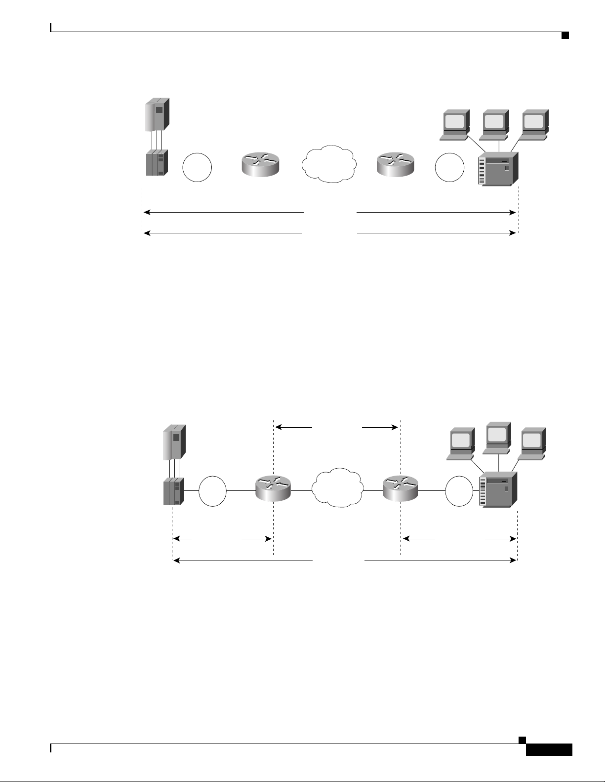
Figure 127 illustrates an LLC2 session in which a 37x5 on a LAN segment communicates with a 3x74
on a different LAN segment separated via a wide-area backbone network. Frames are transported
between Router A and Router B by means of DLSw+. However, the LLC2 session between the 37x5 and
the 3x74 is still end-to-end; that is, every frame generated by the 37 x5 traverses the backbone ne twork
to the 3x74, and the 3x74, on receipt of the frame, acknowledges it.
BC-284
Cisco IOS Bridging and IBM Networking Configuration Guide
78-11737-02
Page 5
Configuring Data-Link Switching Plus
SNA session
3
Figure 127 LLC2 Session without Local Acknowledgment
Technology Overview
Router B
Token
Ring
3x74
S1106a
37x5
Token
Ring
Router A
WAN
LLC2 session
SNA session
On backbone networks consisting of slow serial lin ks, the T1 timer on end hosts could e xpire before th e
frames reach the remote hosts, causing the end host to resend . Resending results in duplicate frames
reaching the remote host at the same time as the first frame reaches the remote host. Such frame
duplication breaks the LLC2 protocol, resulting in the loss of sessions between the two IBM machines.
One way to solve this time delay is to increase the timeout value on the end nodes to account for the
maximum transit time between the two end machines. However, in networks consisting of hundreds or
even thousands of nodes, every machine would need to be reconfigured with new values. With local
acknowledgment for LLC2 enabled, the LLC2 session between the two end nodes would not be not
end-to-end, but instead, would terminate at two local routers. Figure 128 shows the LLC2 session with
the 37x5 ending at Router A and the LLC2 session with the 3x7 4 ending at Router B. Bot h Router A and
Router B execute the full LLC2 protocol as part of local acknowledgment for LLC2.
Figure 128 LLC2 Session with Local Acknowledgment
TCP session
7x5
Token
Ring
Router A
LLC2 session LLC2 session
WAN
Router B
Token
Ring
3x74
S1107a
With local ackno wledgment for LLC2 enabled in both routers, Router A ackno wledges frames received
from the 37x5. The 37x5 still operates as if the acknowledgments it receives are from the 3x74. Router
A looks like the 3x74 to the 37x5. Similarly, Router B acknowledges frames received from the 3x74. The
3x74 operates as if the acknowledgments it receives are from the 37x5. Router B looks like the 3x74 to
37x5. Because the frames do not have to travel the WAN backbone networks to be acknowledged, but
are locally acknowledged by routers, the end machines do not time out, resulting in no loss of sessions.
Cisco IOS Bridging and IBM Networking Configuration Guide
78-11737-02
BC-285
Page 6

Technology Overview
Enabling local acknowledgment for LLC2 has the following advantages:
• Local acknowledgment for LLC2 solves the T1 timer problem without having to change any
configuration on the end nodes. The end nodes are unaware that the sessions are locally
acknowledged. In networks consisting of hun dreds or even thousands of machines, this is a definite
advantage. All the frames acknowledged by the Cisco IOS software appear to the end hosts to be
coming from the remote IBM machine. In fact, by looking at a trace from a protocol analyzer, one
cannot say whether a frame was acknowled ged by the l ocal router or by a remote IBM machin e. The
MAC addresses and the RIFs generated by the Cisco IOS software are identical to those generated
by the remote IBM machine. The only way to f ind out whet her a session is locally ack nowledged is
to use either a show local-ack command or a show sourc e-bridge command on the router.
• All the supervisory (RR, RNR, REJ) frames that are locally acknowledged go no farther than the
router. Without local acknowledgment for LLC2, every frame traverses the backbone.
With local acknowledgment, only data (I-frames) traverse the backbone, resulting in less traffic on
the backbone network. For installations in which customers pay for the amount of traffic passing
through the backbone, this could be a de finite cost-saving measure. A simple p rotocol exists
between the two peers to bring up or down a TCP session.
Notes on Using LLC2 Local Acknowledgment
Configuring Data-Link Switching Plus
LLC2 local acknowledgment is enabled with TCP and DLSw+ Lite remote peers.
If the LLC2 session between the loca l host and the router terminates in either router, the other will be
informed to terminate its connection to its local host.
If the TCP queue length of the connection between the two routers reaches the high-water mark, the
routers sends Receiver -Not- Ready (RNR) messages to the local hosts un ti l the queue limit is r educed to
below this limit. It is possible, ho we ver, to prevent the RNR messages from being sent by using the dlsw
llc2 nornr command.
The configuration of the LLC2 parameters for the local Token Ring interfaces can affect overall
performance. Refer to the chapter “Configuring LLC2 and SDLC Pa rameters” in this manual for more
details about fine-tuning your network through the LLC2 parameters.
The routers at each end of the LLC2 session execute the full LLC2 protocol, which could result in
significant router overhead. The decision to use local acknowledgment for LLC2 should be based on the
speed of the backbone network in relation to the Token Ring speed. For LAN segments separated by
slow-speed serial links (for example, 56 kbps), the T1 timer problem could occur more frequently. In
such cases, it might be wise to turn on local acknowledgment for LLC2. For LAN segments separated
by a T1, backbone delays will be minimal; in such cases, DLSw+, FST or direct encapsulation should
be considered in order to disable local acknowledgement. Speed mismatch between the LAN segments
and the backbone network is one criterion to help you decide to use local acknowledgment for LLC2.
There are some situations (such as the receiving host failing between the time the sending host sends
data and the time the receiving ho st recei ves it), i n which the sending host would determine, at the LLC2
layer, that data was recei ved when it actually was not. This error occurs because the router ackno wledges
that it received data from the sending host before it determines that the receiving host can actually
receive the data. But because both NetBIOS and SNA have error recovery in situations where an end
device goes down, these higher-level protocols will resend any missing or lost data. Because these
transaction request/confirmation prot ocols exist above LLC2, they are not affected by tight timers, as is
LLC2. They also are transparent to local acknowledgment.
BC-286
Cisco IOS Bridging and IBM Networking Configuration Guide
78-11737-02
Page 7

Configuring Data-Link Switching Plus
If you are using NetBIOS applications, note that there are two NetBIOS timers—one at the link level
and one at the next high er lev el. Local acknow ledgment for LLC2 is designed to solv e link timeouts only .
If you are experiencing NetBIOS session timeouts, you have two options:
• Experiment with increasing your NetBIOS timers and decreasing your maximum NetBIOS frame
size.
• Avoid using NetBIOS applications on slow serial lines.
Note By default, the Cisco IOS software translates Token Ring LLC2 to Ethernet 802.3 LLC2. To
configure the router to translat e Token Ring LLC2 frames into Ethernet 0x80d5 format frames, refer
to the section “Enable T ok en Ring LLC2-to-Ethernet Con v ersion” in the “Conf iguring Source-Ro ute
Bridging” chapter of the Cisco IOS Bridging and IBM Networking Command Reference (Volume 1
of 2).
DLSw+ Support for Other SNA Features
DLSw+ can be used as a transport for SNA features such as LNM, DSPU, SNA service point, and SNA
Switching Services (SNASw) through a Cisco IOS feature called virtual data-link control (VDLC).
LNM over DLSw+ allows DLSw+ to be used i n Token Ring networks that are managed by IBM’s LNM
software. Using this feature, LNM can be used to manage Token Ring LANs, control access units, and
Token Ring attached devices over a DLSw+ network. All management functions continue to operate as
they would in a source-route bridged network or an RSRB network.
DSPU over DLSw+ allows Cisco’s DSPU feature to operate in conjunction with DLSw+ in the same
router. DLSw+ can be used either upstream (toward the mainframe) or downstream (away from the
mainframe) of DSPU. DSPU concentration consolidates the appearance of multiple PUs into a single PU
appearance to VTAM , minimizing memory and cycles in central site resources (VTAM, NCP, and
routers) and speeding network startup.
Technology Overview
SNA service point over DLSw+ allo ws Cisco’s SNA service point feature to be used in conjunction with
DLSw+ in the same router. Using this feature, SNA service point can be configured in remote routers,
and DLSw+ can provide the path for the remote service point PU to communicate with NetView. This
allows full management visibility of resou rces from a NetView 390 console, while concurrently of fering
the value-added features of DLSw+ in an SNA network.
SNASw ov er DLSw+ allows Cisco’ s APPN Branch Extender functionality to be used in conjunction with
DLSw+ in the same router. With this feature, DLSw+ can be used to access SNASw in the data center.
DLSw+ can also be used as a transport for SNASw upstream connectivity, providing nondisruptive
recovery from failures.
Using DLSw+ as a transport for other Cisco IOS SNA features requires a feature called VDLC.
Cisco I OS data-link users (such as LNM, DSPU, SNA service point, and SNASw) write to a virtual
data-link control interface. DLSw+ then reads from this interface and sends out the traffic. Similarly,
DLSw+ can receive traffic destined for one of these data-link users and write it to the virtual data-link
control interface, from which the appropriate data-link user will read it.
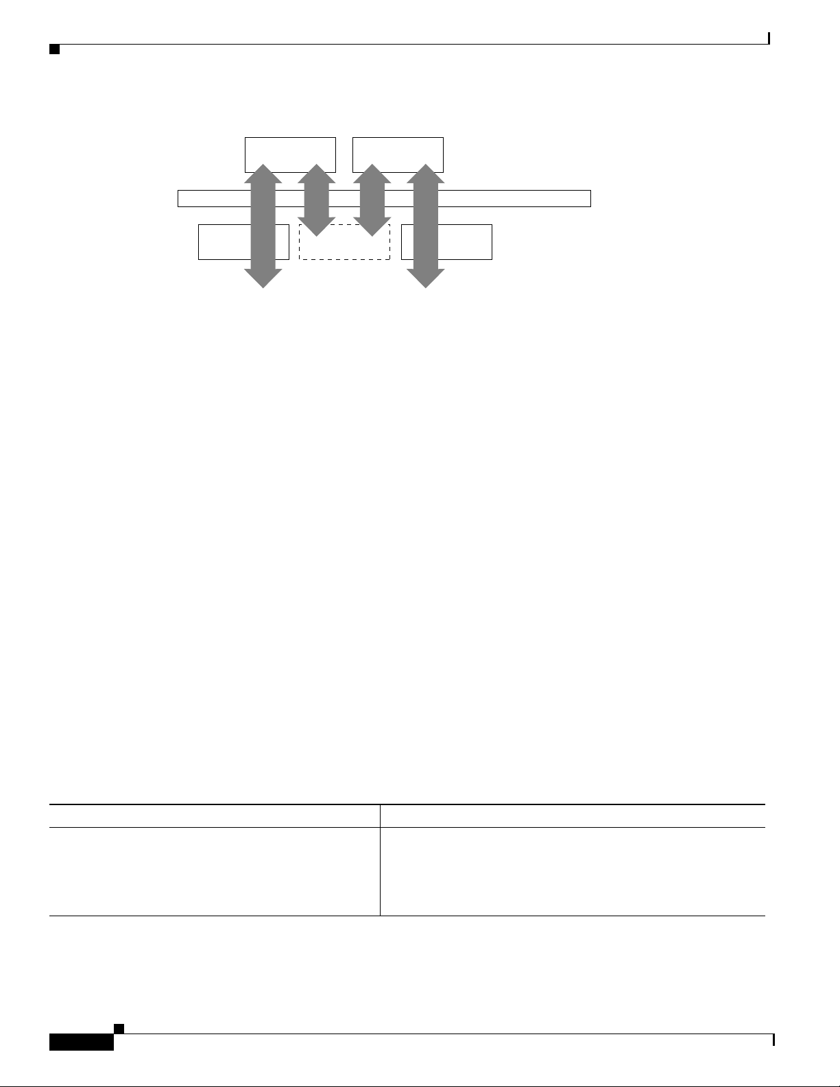
In Figure 129, SNASw and DLSw+ use Token Ring and Ethernet, respectively, as “real” data-link
controls, and use virtual data-link control to communicate between themselves. When one of the
high-layer protocols passes data to the virtual data-link control, the virtual data-link control must pass
it to a higher-layer protocol; nothing leaves the virtual data-link control without going through a
data-link user.
78-11737-02
Cisco IOS Bridging and IBM Networking Configuration Guide
BC-287
Page 8
DLSw+ Configuration Task List
5
ls
Figure 129 VDLC Interaction with Higher-Layer Protocols
Configuring Data-Link Switching Plus
DLSw+ Data-link users
Token
Ring
SNASw
VDLC
The higher-layer protocols make no distinction between the VDLC and any other data-link control, but
they do identify the VDLC as a destination. In the example shown in Figure 129, SNASw has two ports:
a physical port for Token Ring and a virtual port for the VDLC. When you define the SNASw VDLC
port, you can specify the MA C addr ess assigned to it. D ata transpor t from SNASw to DLSw+ by way of
the VDLC is directed to the VDLC MAC address. The type of higher-layer protocol you use determines
how the VDLC MAC address is assigned.
DLSw+ Configuration Task List
DLSw+ supports local or remote media conversion between LANs and SDLC or QLLC.
To configure DLSw+, complete the tasks in the following sections:
• Defining a DLSw+ Local Peer for the Router, page 288
• Defining a DLSw+ Remote Peer, page 289
Ethernet
CLSI
Data-link contro
1909
• Mapping DLSw+ to a Local Data-Link Control, page 292
• Configuring Advanced Features, page 295
• Configuring DLSw+ Timers, page 310
See the “DLSw+ Configuration Examples” section on page 312 for examples.
Defining a DLSw+ Local Peer for the Router
Defining a DLSw+ local peer for a router enables DLSw+. Specify all local DLSw+ parameters as part
of the local peer definition. To define a local peer, use the following command in global configuration
mode:
Command Purpose
Router(config)# dlsw local peer [peer-id
ip-address] [group group] [border] [cluster
cluster-id] [cost cost] [lf size] [keepalive
seconds] [passive] [promiscuous]
[init-pacing-window size] [max-pacing-window
size] [biu-segment]
The following is a sample dlsw local peer statement:
dlsw local peer peer-id 10.2.34.3
Defines the DLSw+ local peer.
BC-288
Cisco IOS Bridging and IBM Networking Configuration Guide
78-11737-02
Page 9

Configuring Data-Link Switching Plus
Defining a DLSw+ Remote Peer
Defining a remote peer in DLSw+ is opti onal, ho we ver , usually at least one side o f a peer connection has
a dlsw remote-peer statement. If you omit the dlsw remote-peer command from a DLSw+ peer
configuration, then you must configure the promiscuous keyword on the dlsw local-peer statement.
Promiscuous routers will accept any peer connection requests from other routers that are not
preconfigured. To define a remote peer, use the dlsw remote-peer command in global configuration
mode.
One of the options in the remote peer statement is to specify an encapsulation type. Configure one of the
following types of encapsulations with the dlsw remote-peer statement:
• TCP Encapsulation, page 289
• TCP/IP with RIF Passthrough Encapsulation, page 290
• FST Encapsulation, page 290
• Direct Encapsulation, page 291
• DLSw Lite Encapsulation, page 291
Which encapsulation type you choose depends on several factors, including whether you want to
terminate the LLC flows. TCP and DLSw+ Lite terminate the LLC, but the other encapsulation types do
not. For details on each encapsulation type, see the DLSw+ Design and Implementation Guide. See the
“Local Acknowledgement” section in the
acknowledgement.
DLSw+ Configuration Task List
overview chapter of this publication for a discussion on local
TCP Encapsulation
To configure TCP encapsulation on a remote peer, use the following command in global configuration
mode:
Command Purpose
Router(config)# dlsw remote-peer list-number tcp
ip-address [
[ip-address | frame-relay interface serial
number dlci-number | interface name]]
[bytes-netbios-out bytes-list-name]
[circuit-weight weight] [cluster cluster-id]
[cost cost] [dest-mac mac-address]
[dmac-output-list access-list-number]
[host-netbios-out host-list-name] [inactivity]
[dynamic] [keepalive seconds] [lf size] [linger
minutes] [lsap-output-list list] [no-llc
minutes] [passive] [priority] [rif-passthru
virtual-ring-number] [tcp-queue-max size]
[timeout seconds]
The following command specifies a dlsw remote peer with TCP encapsulation:
dlsw remote-peer 0 tcp 10.23.4.5
Defines a remote peer with TCP encapsulation.
78-11737-02
Cisco IOS Bridging and IBM Networking Configuration Guide
BC-289
Page 10

DLSw+ Configuration Task List
TCP/IP with RIF Passthrough Encapsulation
To configure TCP/IP with RIF Passthrough encapsulation, use the following command in global
configuration mode:
Command Purpose
Router(config)# dlsw remote-peer list-number tcp
ip-address [backup-peer [ip-address |
frame-relay interface serial number dlci-number
|
interface name]] [bytes-netbios-out
bytes-list-name] [circuit-weight weight] [cost
cost] [dest-mac mac-address] [dmac-output-list
access-list-number] [host-netbios-out
host-list-name] [inactivity] [dynamic]
[keepalive seconds] [lf size] [linger minutes]
[lsap-output-list list] [no-llc minutes]
[passive] [priority] [rif-passthru
virtual-ring-number] [tcp-queue-max size]
[timeout seconds]
The following command specifies a remote peer with TCP/IP with RIF Passthrough encapsulation:
dlsw remote-peer 0 tcp 10.2.23.5 rif-passthru 100
Defines a remote peer with TCP/IP with RIF Passthrough
encapsulation.
Configuring Data-Link Switching Plus
FST Encapsulation
To configure FST encapsulation on a remote peer, use the following command in global configuration
mode:
Command Purpose
Router(config)# dlsw remote-peer list-number fst
ip-address [backup-peer [ip-address |
frame-relay interface serial number dlci-number
| interface name]]
[bytes-netbios-out bytes-list-name]
[circuit-weight weight] [cost cost] [dest-mac
mac-address] [dmac-output-list
access-list-number] [host-netbios-out
host-list-name] [keepalive seconds] [lf size]
[linger minutes] [lsap-output-list list]
The following command specifies a DLSw remote peer with FST encapsulation:
dlsw remote-peer 0 fst 10.2.23.5
Defines a remote peer with FST encapsulation.
BC-290
Cisco IOS Bridging and IBM Networking Configuration Guide
78-11737-02
Page 11

Configuring Data-Link Switching Plus
Direct Encapsulation
To configure direct encapsulation, use the following command in global configuration mode:
Command Purpose
Router(config)# dlsw remote-peer list-number
frame-relay interface serial number dlci-number
[backup-peer [ip-address | frame-relay interface
serial number dlci-number | interface name]]
[bytes-netbios-out bytes-list-name]
[circuit-weight weight] [cost cost] [dest-mac
mac-address] [dmac-output-list
access-list-number] [host-netbios-out
host-list-name] [keepalive seconds] [lf size]
[linger minutes] [lsap-output-list list]
pass-thru
Direct encapsulation is supported over High-Level Data Link Control (HDLC) and Frame Relay.
The following command specifies a DLSw remote peer with direct encapsulation over HDLC:
dlsw remote-peer 0 interface serial 01
Defines a remote peer with direct encapsulation.
DLSw+ Configuration Task List
Direct encapsulation over Frame Relay comes in two forms: DLSw Li te (LLC2 encap sulatio n) and
Passthrough. Specifying the pass-thru option con figures the router so that the traffic will not be locally
acknowledged. (DLSw+ normally locally acknowledges traffic to keep traffic on the WAN to a
minimum.)
The following command specifies a DLSw remote peer with Direct encapsulation with pass-thru over
Frame Relay:
dlsw remote-peer 0 frame-relay interface serial 01 pass-thru
DLSw+ Lite is described in the “DLSw Lite Encapsulation” section on page 291.
DLSw Lite Encapsulation
To configure DLSw Lite encapsulation, use the following command in global configuration mode:
Command Purpose
Router(config)# dlsw remote-peer list-number
frame-relay interface serial number dlci-number
[backup-peer [ip-address | frame-relay interface
serial number dlci-number | interface name]]
[bytes-netbios-out bytes-list-name]
[circuit-weight weight] [cost cost] [dest-mac
mac-address] [dmac-output-list
access-list-number] [host-netbios-out
host-list-name] [keepalive seconds] [lf size]
[linger minutes] [lsap-output-list list]
pass-thru
Defines a remote peer with DLSw Lite encapsula tion.
78-11737-02
The following command specifies a DLSw remote peer with DLSw Lite encapsulation over Frame
Relay:
dlsw remote-peer 0 frame-relay interface serial 01
Cisco IOS Bridging and IBM Networking Configuration Guide
BC-291
Page 12

DLSw+ Configuration Task List
Mapping DLSw+ to a Local Data-Link Control
In addition to configuring local and remote peers, you must map one of the following local data-link
controls to DLSw+:
• Token Ring, page 292
• Ethernet, page 293
• SDLC, page 293
• QLLC, page 294
• FDDI, page 295
Token Ring
Traffic that originates from Token Ring is source-route bridged from the local ring onto a source-bridge
ring group and then picked up b y DLSw+. You must include a sour ce-bridge ring-gr oup command that
specifies a virtual ring number when configuring Token Ring with DLSw+. In addition, you must
configure the source-bridge command that tells the DLSw+ router to bridge from the physical Token
Ring to the virtual ring.
Configuring Data-Link Switching Plus
To specify a virtual ring number, use the following command in global configuration mode:
Command Purpose
Router(config)# source-bridge ring-group
ring-group [virtual-mac-address]
Defines a virtual ring.
To enable DLSw+ to bridge from the physical Token Ring ring to the virtual ring, use the following
command in interface mode:
Command Purpose
Router(config-if)# source-bridge
source-ring-number bridge-number
target-ring-number
Defines SRB on interface.
To enable single-route explorers, use the following command in interface mode:
Command Purpose
Router(config-if)# source-bridge spanning
Enables single-route explorers.
Configuring the source-bridge spanning command is required because DLSw+ uses single-route
explorers by default.
BC-292
The following command configures a source-bridge ring-group and a virtual ring with a value of
100toDLSw+:
source-bridge ring-group 100
int T0
source-bridge 1 1 100
source-bridge spanning
The ring-group number specified in the source-bridge command must be the number of a defined
source-bridge ring-group or DLSw+ will not see this interface.
Cisco IOS Bridging and IBM Networking Configuration Guide
78-11737-02
Page 13

Configuring Data-Link Switching Plus
Ethernet
Traffic that originates from Ethernet is picked up from the local Ethernet interface bridge group and
transported across the DLSw+ network. Therefore, you must map a specific Ethernet bridge group to
DLSw+.
To map an Ethernet bridge group to DLSw+, use the following command in global configuration mode:
Command Purpose
Router(config)# dlsw bridge-group group-number
[llc2 [N2 number] [ack-delay-time milliseconds]
[ack-max number] [idle-time milliseconds]
[local-window number] [t1-time milliseconds]
[tbusy-time milliseconds] [tpf-time
milliseconds] [trej-time milliseconds]
[txq-max number] [xid-neg-val-time milliseconds]
[xid-retry-time milliseconds]] [locaddr-priority
lu address priority list number] [sap-priority
priority list number]
T o assign the Ethernet interface to a bridg e group, use the follo wing command in i nterface conf iguration
mode:
Links DLSw+ to the bridge group of the Ethernet LAN.
DLSw+ Configuration Task List
Command Purpose
Router(config-if)# bridge-group bridge-group
Assigns the Ethernet interface to a bridge group.
The following command maps bridge-group 1 to DLSw+:
dlsw bridge-group 1
int E1
bridge-group 1
bridge 1 protocol ieee
SDLC
Configuring SDLC devices is more complicated than configuring Ethernet and Token Ring. There are
several considerations that affect which interface commands are configured. See the DLSw+ Design and
Implementation Guide for more details.
To establish devices as SDLC stations, use the following commands in interface configuration mode:
Command Purpose
Step 1
Step 2
Step 3
Step 4
Step 5
Router(config-if)# encapsulation
sdlc
Router(config-if)# sdlc role {none |
primary | secondary | prim-xid-poll}
Router(config-if)# sdlc vmac
mac-address
Router(config-if)# sdlc address
hexbyte [echo]
Router(config-if)# sdlc partner
mac-address sdlc-address {inbound |
outbound}
1
Sets the encapsulation type of the serial interface to SDLC.
Establishes the role of the in terface.
Configures a MAC address for the serial interface.
Assigns a set of secondary stations attached to the serial link.
Specifies the destination address with which an LLC session is
established for the SDLC station .
78-11737-02
Cisco IOS Bridging and IBM Networking Configuration Guide
BC-293
Page 14

DLSw+ Configuration Task List
Command Purpose
Step 6
Step 7
Router(config-if)# sdlc xid
Router(config-if)# sdlc dlsw
{sdlc-address | default | partner
mac-address [inbound | outbound]}
1. The last byte of the MAC address must be 00.
Configuring Data-Link Switching Plus
Specifies an XID value appropriate for the designated SDLC station
associated with this serial interface.
Enables DLSw+ on an SDLC interface.
Use the default option if you have more than 10 SDLC devices to attach to the DLSw+ network. To
configure an SDLC multidrop line downstream, you configure the SDLC role as either primary or
prim-xid-poll. SDLC role primary specifies that any PU without the xid-poll parameter in the
sdlc address command is a PU 2.0 device. SDLC role prim-xid-poll specifies that e very PU is ty pe 2.1.
We recommend that you specify sdlc role primary if all SDLC devices are type PU 2.0 or a mix of
PU 2.0 and PU 2.1. Specify sdlc role prim-xid-poll if all devices are type PU 2.1.
To configure DLSw+ to support LLC2-to-SDLC conversion for PU 4 or PU 5 devices, specify the echo
option in the sdlc address command. A PU 4-to-PU 4 configuration requires that none be specified in
the sdlc role command.
Refer to the “DLSw+ with SDLC Multidrop Support Configuration Examples” section on page 318 and
the “DLSw+ with LLC2-to-SDLC Conversion Between PU 4-to-PU 4 Communication Example” section
on page 319 for sample configurations.
The following configuration shows a DLSw+ router configured for SDLC:
dlsw local-peer peer-id 10.2.2.2
dlsw remote-peer 0 tcp 10.1.1.1
interface Serial1
mtu 6000
no ip address
encapsulation sdlc
no keepalive
nrzi-encoding
clockrate 9600
sdlc vmac 4000.3745.0000
sdlc N1 48016
sdlc address 04 echo
sdlc partner 4000.1111.0020 04
sdlc dlsw 4
QLLC
BC-294
SNA devices use QLLC when connecting to X.25 networks. QLLC essentially emulates SDLC over
x.25. Therefore, configuring QLLC devices is also complicated. There are several considerations that
affect which interface commands are configured. See the DLSw+ Design and Implementation Guide for
details.
You can configure DLSw+ for QLLC connectivity, which enables both of the following scenarios:
• Remote LAN-attached devices (physical units) or SDLC-attached devices can access an FEP or an
AS/400 over an X.25 network.
Our QLLC support allows remote X.25-attached SNA devices to access an FEP with out requiring
X.25 NCP Packet Switching Interface (NPSI) in the FEP. This may eliminate the requirement for
NPSI (if GATE and DATE are not required), thereby eliminating the recurring license cost. In
addition, because the QLLC attached devices appear to be Token Ring-attached to the Network
Control Program (NCP), they require no preconf iguration in the FEP. Remote X.25-attached SNA
devices can also connect to an AS/400 over Token Ring using this suppo rt.
Cisco IOS Bridging and IBM Networking Configuration Guide
78-11737-02
Page 15

Configuring Data-Link Switching Plus
• Remote X.25-attached SNA devices can access an FEP or an AS/400 over a Token Ring or over
T o enable QLLC connectivity for DLSw+, use the follo wing commands in interf ace conf iguration mo de:
Command Purpose
Step 1
Step 2
Step 3
Step 4
Router(config-if)# encapsulation x
25
Router(config-if)# x25 address
subaddress
Router(config-if)# x25 map qllc
virtual-mac-addr x121-addr
[cud cud-value] [x25-map-options]
Router(config-if)# qllc dlsw
{subaddress subaddress | pvc pvc-low
[pvc-high]} [vmac vmacaddr
[poolsize]] [partner
partner-macaddr] [sap ssap dsap]
[xid xidstring] [npsi-poll]
DLSw+ Configuration Task List
SDLC.
For environments just beginning to migrate to LANs, our QLLC support allows deployment of
LANs in remote sites while maintaining access to the FEP over existing NPSI links. Remote
LAN-attached devices (physical units) or SDLC-attached devices can access a FEP over an X.25
network without requiring X.25 hardware or software in the LAN-attached devices. The Cisco IOS
software supports direct attachment to the FEP over X.25 without the need for routers at the data
center for SNA traffic.
Specifies an interface as an X.25 device.
Activates X.25 subaddresses.
Associates a virtual MAC address with the X.121 address of the remot e
X.25 device.
Enables DLSw+ over QLLC.
The following configuration enables QLLC connectivity for DLSw+:
dlsw local-peer peer-id 10.3.12.7
dlsw remote-peer 0 tcp 10.3.1.4
interface S0
encapsulation x25
x25 address 3110212011
x25 map qllc 1000.0000.0001 3 1104150101
qllc dlsw partner 4000.1151.1234
FDDI
Configure an FDDI interface the same as a Token Ring or Ethernet interface, depending on whether you
are configuring SRB or Transparent Bridging. If you are configuring the router for SRB, configure the
FDDI interface for T ok en Ring. If you are conf iguring the router for T ransparent Br idging, configur e the
FDDI interface for Ethernet.
Configuring Advanced Features
DLSw+ goes beyond the standard to include additional functionality in the following areas:
• Scalability , page 296⎯Constructs IBM internetworks in a way that reduces the amount of broadcast
traffic, which enhances their scalability.
• Availability, page 303⎯Dynamically finds alternate paths and, optionally, load-balances across
multiple active peers, ports, and channel gateways.
78-11737-02
Cisco IOS Bridging and IBM Networking Configuration Guide
BC-295
Page 16

DLSw+ Configuration Task List
Scalability
Configuring Data-Link Switching Plus
• Modes of Operation, page 306⎯Dynamically detects the capabilities of the peer router and operates
according to those capabilities.
• Network Management, page 307—Works with enhanced network management tools such as
CiscoW orks Blue Maps, CiscoWorks SNA V iew, and CiscoWorks Blue Internetw ork Status Monitor
(ISM).
• Traffic Bandwidth and Queueing Management, page 307—Offers several bandwidth management
and queueing features to enhance the overall performance of your DLSw+ network. Controls
different types of explorer traffic using multiple queues, each with a wide range of depth settings.
• Access Control, page 307—Provides access control to various resources throughout a network.
One significant factor that limits the size of Token Ring internet works is the amount of explorer traffic
that traverses the WAN. DLSw+ includes the following features to reduce the number of explorers:
• Peer Groups and Border Peers, page 296
• Explorer Firewalls, page 300
• NetBIOS Dial-on-Demand Routing, page 300
• SNA Dial-on-Demand Routing, page 301
• UDP Unicast Feature, page 301
• LLC1 Circuits, page 302
• Dynamic Peers, page 302
• Promiscuous Peer Defaults, page 302
Peer Groups and Border Peers
Perhaps the most significant optimization in DLSw+ is a feature kn own as peer groups. Peer groups are
designed to address the broadcast replication that occurs in a fully meshed network. When any-to-any
communication is required (for example, for NetBIOS or Advanced Peer-to-Peer Networking [APPN]
environments), RSRB or standard DLSw implementations require peer connections between every pair
of routers. This setup is not only difficult to configure, but it results in branch access routers having to
replicate search requests for each peer connection. This setup wastes bandwidth and router cycles. A
better concept is to group routers into cl usters and designate a focal router t o be responsible for broadcast
replication. This capability is included in DLSw+.
With DLSw+, a cluster of routers in a region or a division of a company can be combined into a peer
group. Within a peer group, one or more of the ro uters is d esignated to be th e border peer. Inst ea d of all
routers peering to one another, each router within a group peers to the border peer; and border peers
establish peer connections with each other. When a DLSw+ router receives a TEST frame or NetBIOS
NAME-QUERY, it sends a single explorer frame to its border peer. The DLSw+ border peer router
checks its local, remote and group cache for any reachability information before forwarding the explorer .
If no match is found, the border peer forwards the explorer on behalf of the peer group member. If a
match is found, the border peer sends the explorer to the appropriate peer or border peer. This setup
eliminates duplicate explorers on the access links and minimizes the processing required in access
routers.
You can further segment DLSw+ routers within the same border peer group that are serving the same
LANs into a peer cluster. This segmentation reduces explorers because the border peer recognizes that
it only has to forward an explorer to one member within a peer cluster. Only TCP encapsulation can be
used with the DLSw+ Peer Clusters feature.
BC-296
Cisco IOS Bridging and IBM Networking Configuration Guide
78-11737-02
Page 17

Configuring Data-Link Switching Plus
The DLSw+ Peer Clusters feature is configured locally on the member peer or on a border peer . Although
both options can be configured, we recommend that the cluster-id of a particular peer is defined in either
the border peer or on the member peer, but not both because of potential configuration confusion.
DLSw+ Configuration Task List
78-11737-02
Cisco IOS Bridging and IBM Networking Configuration Guide
BC-297
Page 18

DLSw+ Configuration Task List
To define peer groups, configure border peers and assign the local peer to a peer cluster, use the
following command in global configuration mode:
Command Purpose
Router(config)# dlsw local-peer [peer-id
ip-address] [group group] [border] [cost cost]
[cluster cluster-id] [lf size] [keepalive
seconds] [passive] [promiscuous] [biu-segment]
[init-pacing-window size] [max-pacing-window
size]
Use the group keyword to define a peer group, the border keyword to define a border peer and the
cluster keyword to assign the local peer to a peer cluster. When the user defines the cluster option in
the dlsw local-peer command on the member peer router, the cluster information is exchanged with the
border peer during the capabilities exchange as the peers become active. The border peer uses this
information to make explorer replication and forwarding decisions.
The following command configures the router as the Border peer that is a member of group 2:
dlsw local-peer peer-id 10.2.13.4 group 2 border
Enables peer groups and border peers.
Configuring Data-Link Switching Plus
Configure the cluster option in the dlsw remote-peer command on a border peer to enable the DLSw+
Peer Clusters feature without forcing every DLSw+ router in the network to upgrade their software. To
enable the DLSw+ Peer Clusters feature on a Border Peer, use the following command in global
configuration mode:
Command Purpose
Router(config)# dlsw remote-peer list-number tcp
ip-address [backup-peer [ip-address |
frame-relay interface serial number dlci-number
|
interface name]] [bytes-netbios-out
bytes-list-name] [circuit-weight weight]
[cluster cluster-id] [cost cost] [dest-mac
mac-address] [dmac-output-list
access-list-number] [host-netbios-out
host-list-name] [inactivity] [dynamic]
[keepalive seconds] [lf size] [linger minutes]
[lsap-output-list list] [no-llc minutes]
[passive] [priority] [rif-passthru
virtual-ring-number] [tcp-queue-max size]
[timeout seconds]
Defines the border peer router as part of a particular cluster and
enables the DLSw+ Peer Clusters feature.
The following command configures a border router as a member of cluster 5:
dlsw remote-peer tcp 10.2.13.5 cluster 5
A peer-on-demand peer is a non-configured remote-peer that was connected because of an LLC2 session
established through a border peer DLSw+ network. On-demand peers greatly reduce the number of peers
that must be configured. You can use on-demand peers to establish an end-to-end ci rcuit e ven though the
DLSw+ routers servicing the end systems have no specific configuration information about the peers.
This configuration permits casual, any-to-any connection without the burden of configuring the
connection in advance. It also allows an y-to -an y switching in large internetworks where pers is te nt TCP
connections would not be possible.
BC-298
Cisco IOS Bridging and IBM Networking Configuration Guide
78-11737-02
Page 19

Configuring Data-Link Switching Plus
To configure peer-on-demand defaults, use the following command in global configuration mode:
Command Purpose
Router(config)# dlsw peer-on-demand-defaults
[fst] [bytes-netbios-out bytes-list-name] [cost
cost] [dest-mac destination mac-address]
[dmac-output-list access-list-number]
[host-netbios-out host-list-name] [inactivity
minutes] [keepalive seconds] [lf size]
[lsap-output-list list] [port-list
port-list-number] [priority] [tcp-queue-max]
To define the maximum entries maintained in a border peer’s group cache, use the following command
in global configuration mode:
Command Purpose
Router(config)# dlsw group-cache max-entries
number
Configures peer-on-demand defaults.
Defines the maximum entries in a group cache.
DLSw+ Configuration Task List
To remove all entries from the DLSw+ reachability cache, use the following command in privileged
EXEC mode:
Command Purpose
Router# clear dlsw reachability
Removes all entries from the DLSw+ reachability cache.
To reset to zero the number of frames that have been processed in the local, remote and group caches,
use the following command in privileged EXEC mode:
Command Purpose
Router# clear dlsw statistics
Resets to zero the number of frames that have been processed in
the local, remote, and group caches.
To disable the border peer caching feature, use the following command in global configuration mode:
Command Purpose
Router(config-if)# dlsw group-cache disable
Disables the border peer caching feature.
To verify that the peer cluster feature is enabled or that the border peer is configured, issue the show
dlsw capabilities command on the router . To verify the cluster id number of which the peer is a member,
issue the show dlsw capabilities local command on the local router.
78-11737-02
Cisco IOS Bridging and IBM Networking Configuration Guide
BC-299
Page 20

DLSw+ Configuration Task List
To display the contents of the reachability caches, use the following command in privileged EXEC
command mode:
Command Purpose
Router# show dlsw reachability [[group [value] |
local | remote] | [mac-address [address]
[netbios-names [name]
Use the group keyword to display the reachability information for the border peer.
Explorer Firewalls
An explorer fire wall permits only a single expl orer for a particular destination MA C address or NetBIOS
name to be sent across the WAN. While an explorer is outstanding and awaiting a response from the
destination, subsequent explorers for that MAC address or NetBIOS name are merely stored. When the
explorer response is received at the originating DLSw+, all explorers receive an immediate local
response. This eliminates the start-of-day explorer storm that many networks experience. Configure the
dlsw timer command to enable explorer firewalls. See the “Configuring DLSw+ Timers” section on
page 310 for details of the command.
Displays content of group, local and remote caches.
Configuring Data-Link Switching Plus
To enable explorer firewalls, use the following command in global configuration mode:
Command Purpose
Router(config)# dlsw timer
{icannotreach-block-time | netbios-cache-timeout
| netbios-explorer-timeout | netbios-group-cache
| netbios-retry-interval |
netbios-verify-interval | sna-cache-timeout |
explorer-delay-time | sna-explorer-timeout |
explorer-wait-time | sna-group-cache |
sna-retry-interval | sna-verify-interval} time
Tunes an existing configuration parameter.
NetBIOS Dial-on-Demand Routing
This feature allows you to transport NetBIOS in a dial-on-demand routing (DDR) environment by
filtering NetBIOS Session Alive packets from the WAN. NetBIOS periodically sends Session Alive
packets as LLC2 I-frames. These packets do not require a response and are superfluous to the function
of proper data flow. Furthermore, these packets keep dial-on-demand interfaces up and this up time
causes unwanted per-packet charges in DDR networks. By filtering these NetBIOS Session Alive
packets, you reduce traffic on the WAN and you reduce some costs that are associated with
dial-on-demand routing.
To enable NetBIOS DDR, use the following command in global configuration mode:
Command Purpose
Router(config)# dlsw netbios keepalive-filter
Enables NetBIOS DDR.
BC-300
The following command enables NetBIOS DDR:
dlsw netbios keepalive-filter
Cisco IOS Bridging and IBM Networking Configuration Guide
78-11737-02
Page 21

Configuring Data-Link Switching Plus
SNA Dial-on-Demand Routing
This feature allows you to run DLSw+ over a switched line and have the Cisco IOS software take the
switched line down dynamically when it is not in use. Utilizing this feature gives the IP Routing table
more time to converge when a network problem hinders a remote peer connection. In small networks
with good IP convergence time and ISDN lines that start quickly, it is not as necessary to use the
keepalive option. To use this feat ure, you must set th e keepalive value to zero, and you may need to use
a lower value for the timeout option than the default, which is 90 seconds.
To configure SNA DDR, use the following command in global configuration mode:
Command Purpose
Router(config)# dlsw remote-peer list-number tcp
ip-address [backup-peer [ip-address |
frame-relay interface serial number dlci-number
|
interface name]] [bytes-netbios-out
bytes-list-name] [circuit-weight weight]
[cluster cluster-id] [cost cost] [dest-mac
mac-address] [dmac-output-list
access-list-number] [host-netbios-out
host-list-name] [inactivity] [dynamic]
[keepalive seconds] [lf size] [linger minutes]
[lsap-output-list list] [no-llc minutes]
[passive] [priority] [rif-passthru
virtual-ring-number] [tcp-queue-max size]
[timeout seconds]
Configures SNA DDR.
DLSw+ Configuration Task List
The following command configures the SNA DDR feature:
dlsw remote-peer 0 tcp 10.2.13.4 keepalive 0
UDP Unicast Feature
The UDP Unicast feature sends the SSP address resolution packets via UDP unicast service rather than
TCP. (SSP packets include: CANUREACH_EX, NETBIOS_NQ_ex, NETBIOS_ANQ, and
DAT AFRAME.) The UDP unicast feature allows DLSw+ to better control address resolution packets and
unnumbered information frames during periods of congestion. Previously, these frames were carried
over TCP. TCP resends frames that get lost or delayed in transit, and hence aggravate congestion.
Because address resolution packets and unnumbered information frames are not sent on a reliable
transport on the LAN, sending them reliably over the WAN is unnecessary. By using UDP for these
frames, DLSw+ minimizes network congestion.
Note UDP unicast enhancement has no affect on DLSw+ FST or direct peer encapsulation.
This feature is enabled by default. To disable User Datagram Protocol (UDP) Unicast, use the following
command in global configuration mode:
Command Purpose
Router(config)# dlsw udp-disable
Disables UDP Unicast.
78-11737-02
Cisco IOS Bridging and IBM Networking Configuration Guide
BC-301
Page 22

DLSw+ Configuration Task List
LLC1 Circuits
Support for LLC1 circuits more efficiently transports LLC1 UI traffic across a DLSw+ cloud. With
LLC1 circuit support, the LLC1 unnumbered information frames (UI) are no longer subject to input
queueing and are guaranteed to traverse the same path for the duration of the flo w . This featur e improv es
transportation of LLC1 UI traffic because there is no longer the chance of having a specifically routed
LLC1 UI frame broadcast to all remote peers. The circuit establishment process has not changed except
that the circuit is established as soon as the specifically routed LLC1 UI frame is received and the
DLSw+ knows of reachability for the destination MAC address. Furthermore, the connection remains in
the CIRCUIT_EST ABLISHED state (rather than proceeding to the CONNECT state) until there is no UI
frame flow for a MAC/SAP pair for 10 minutes.
This feature is enabled by default.
Dynamic Peers
In TCP encapsulation, the dynamic option and its suboptions no-llc and inactivity allo w you to specify
and control the activation of dynamic peers, which are configured peers that are activated only when
required. Dynamic peer connections are established only when there is DLSw+ data to send. The
dynamic peer connections are taken down when th e last LLC2 connection using them terminates and the
time period specified in the no-llc option expires. You can also use the inactivity option to take down
dynamic peers when the circuits using them are inactive for a specified number of minutes.
Configuring Data-Link Switching Plus
Note Because the inactivity option may cause active LLC2 sessions to be term inated, you should not use
this option unless you want active LLC2 sessions to be terminated.
To configure a dynamic peer, use the following command in global configuration mode:
Command Purpose
Router(config)# dlsw remote-peer list-number tcp
ip-address [backup-peer [ip-address |
frame-relay interface serial number dlci-number
| interface name]] [bytes-netbios-out
bytes-list-name] [circuit-weight weight]
[cluster cluster-id] [cost cost] [dest-mac
mac-address] [dmac-output-list
access-list-number] [host-netbios-out
host-list-name] [inactivity] [dynamic]
[keepalive seconds] [lf size] [linger minutes]
[lsap-output-list list] [no-llc minutes]
[passive] [priority] [rif-passthru
virtual-ring-number] [tcp-queue-max size]
[timeout seconds]
Configures a dynamic peer.
The following command specifies a dynamic peer with TCP encapsulation:
dlsw remote-peer 0 tcp 10.23.4.5 dynamic
Promiscuous Peer Defaults
If you do not configure a dlsw remote-peer statement on the DLSw+ router, then you must specify the
promiscuous keyword on the dlsw local-peer statement. The promiscuous keyword enables the router
to accept peer connection requests from those routers that are not preconfigured. Setting the dlsw
prom-peer-defaults command allows the user to determine various settings for the promiscuous
transport.
BC-302
Cisco IOS Bridging and IBM Networking Configuration Guide
78-11737-02
Page 23

Configuring Data-Link Switching Plus
To configure promiscuous peer defaults, use the following command in global configuration mode :
Command Purpose
Router(config)# dlsw prom-peer-defaults
[bytes-netbios-out bytes-list-name] [cost cost]
[dest-mac destination-mac-address]
[dmac-output-list access-list-number]
[host-netbios-out host-list-name] [keepalive
seconds] [lf size] [lsap-output-list list]
[tcp-queue-max size]
Configures promiscuous peer defaults.
Availability
DLSw+ supports the following features that allow it to dynamically finds alternate paths quickly and
optionally load balances across multiple active peers, ports, and channel gateways:
• Load Balancing, page 303
• Ethernet Redundancy, page 305
• Backup Peers, page 305
DLSw+ Configuration Task List
Load Balancing
DLSw+ offers enhanced availability by caching multiple paths to a given MAC address or NetBIOS
name (where a path is either a remote peer or a local port). Maint aining mul tiple paths per destination is
especially attractive in SNA networks. A common technique used in the hierarchical SNA environment
is assigning the same MAC address to different Token Ring interface couplers (TICs) on the IBM FEPs.
DLSw+ ensures that duplicate TIC addresses are found, and, if multiple DLSw+ peers can be used to
reach the FEPs, they are cached.
The way that multiple capable peers are handled with DLSw+ can be configured to meet either of the
following network needs:
• Fault tolerance—To rapidly reconnect if a data-link connection is lost. If load balancing is not
enabled, the Cisco IOS software, by default, maintains a preferred path and one or more capable
paths to each destination. The preferred path is either the peer or port that responds first to an
explorer frame or the peer with the least cost. If the preferred path to a given destination is
unavailable, the next available capable path is promoted to the new preferred path. No additional
broadcasts are required, and recovery through an alternate peer is immediate. Maintaining multip le
cache entries facilitates a timely reconnection after session outages.
A peer with the least cost can also be the preferred path. Y ou can specify cost in either the dlsw local
peer or dlsw remote peer commands. See the DLSw+ Design and Impl ementation Guide for details
on how cost can be applied to control which path sessions use.
• Load balancing—To distribute the network traffic over multiple DLSw+ peers in the network.
Alternately, when there are duplicate paths to the destination end system, you can configure load
balancing. DLSw+ alternates new circuit requests in either a ro und-robin or enhanced load
balancing fashion through the list of capable peers o r ports. If round-robin is configured, the router
distributes the new circuit in a round-robin fashion, basing it’s decision on which peer or port
established the last circuit. If enhanced load balancing is configured, the router distributes new
circuits based on existing loads and the desired ratio. It detects the path that is underloaded in
comparison to the other capable peers and wil l assign ne w ci rcuits to that path until the d esired ratio
is achieved.
78-11737-02
Cisco IOS Bridging and IBM Networking Configuration Guide
BC-303
Page 24

DLSw+ Configuration Task List
For multiple peer connections, peer costs must be applied. The DLSw+ Enhanced Load Balancing
feature works only with the lowest (or equal) cost peers. For e xample, if the user specif ies dlswrt r1,
dlswrtr2 and dlswrtr3 with costs of 4, 3, and 3 respectively, DLSw+ establishes new circuits with
only dlswrtr 2 and dlswrtr3.
T o enab le the DLSw+ Enha nced Load Ba lancing fea ture on the lo cal router, use the following command
in global configuration mode:
Command Purpose
Router(config)# dlsw load-balance [round-robin |
circuit count circuit-weight]
To adjust the circuit weight for a remote peer with TCP encapsulation, use the following command in
global configuration mode:
Command Purpose
Router(config)# dlsw remote-peer tcp
[circuit-weight value]
Configures the DLSw+ Enhanced Load Balancing feature on the
local router.
Adjusts the circuit weight on the remote peer.
Configuring Data-Link Switching Plus
To adjust the circuit weight for a remote peer with DLSw+ Lite encapsulation, use the following
command in global configuration mode:
Command Purpose
Router(config)# dlsw remote-peer frame-relay
interface serial number dlci number
[circuit-weight value]
Adjusts the circuit weight on the remote peer.
The circuit-weight of a remote peer controls the number of circuits that peer can take. If multiple, equally
low-cost peers can reach a remote source, the circuits to that remote source are distributed among the
remote peers based on the ratio of thei r configured circuit-weights. The peer with the highest
circuit-weight takes more circuits.
Because a DLSw+ peer selects its new circuit paths from within its reachability cache, the user must
configure the dlsw timer explorer-wait-time command with enough time to allow for all the explorer
responses to be received. If the new DLSw+ Enhanced Load Balancing Feature is enabled, a messag e is
displayed on the console to alert the user if the timer is not set.
To configure the amount of time needed for all the explorer responses to be received, use the following
command in global configuration mode:
Command Purpose
Router(config)# dlsw timer {explorer-wait-time}
Sets the time to wait for all stations to respond to explorers.
BC-304
See the DLSw+ Design and Implementation Guide for details on how to configure load balancing in
DLSw+. Refer to the “DLSw+ with Enhanced Load Balanc ing Configuratio n Example” sec tion on
page 327 for a sample configuration.
Cisco IOS Bridging and IBM Networking Configuration Guide
78-11737-02
Page 25

Configuring Data-Link Switching Plus
Ethernet Redundancy
The DLSw+ Ethernet Redundancy feature, introduced in Cisco IOS Release 12.0(5)T, provides
redundancy and load balancing between multiple DLSw+ peers in an Ethernet environment. It enables
DLSw+ to support parallel paths between two points in an Ethernet environment, ensuring resiliency in
the case of a router failure and pro viding load balancing for traf fic load. The feature also enables DLSw+
to support multiple DLSw+ routers on the same transparent bridged domain that can reach the same
MAC address in a switched environment
To enable the DLSw+ Ethernet Redundancy feature, issue the following command in interface
configuration mode:
Command Purpose
Router(config-if)# dlsw transparent
redundancy-enable
Configures transparent redundancy.
To enable the DLSw+ Ethernet Redundancy feature in a switched environment, enter the following
commands in interface configuration mode:
DLSw+ Configuration Task List
.
Step 1
Step 2
Command Purpose
Router(config-if)# dlsw transparent
switch-support
Router(config-if)# dlsw transparent
map local mac mac address remote mac
mac address neighbor mac address
Enables DLSw+ Ethernet Redundancy feature when using a switch
device.
Configures a single destination MAC address to which multiple MAC
addresses on a transparent bridged are mapped.
The Ethernet Redundancy feature is a complex feature. See the DLSw+ Design and Implementation
Guide for more details. Refer to the “DLSw+ with Ethernet Redundancy Configuration Example”
section on page 331 and the “DLSw+ with Ethernet Redundancy Enabled for Switch Support
Configuration Example” section on page 332 for sample configurations.
Backup Peers
The backup-peer option is common to all encapsulation types on a remote peer and specifies that this
remote peer is a backup peer for the router with the specified IP-address, Frame Relay Data-Link Control
Identifier (DLCI) number, or interface name. When the primary peer fails, all circuits ov er this peer are
disconnected and the user can start a new session via their backup peer. Prior to Cisco IOS
Release 11.2(6)F, you could configure backup peers only for primary FST and TCP.
Also, when you specify the backup-peer option in a dlsw remote-peer tcp command, the backup peer
is activated only when the primary peer becomes unreachable. Once the primary peer is reactivated, all
new sessions use the primary peer and the backup peer remains active only as long as there are LLC2
connections using it. You can use the linger option to specify a period (in mi nutes) that t he backu p peer
remains connected after the connection to the primary peer is reestablished. When the linger period
expires, the backup peer connection is taken down.
78-11737-02
Cisco IOS Bridging and IBM Networking Configuration Guide
BC-305
Page 26

DLSw+ Configuration Task List
Note If the linger keyword is set to 0, all existing sessions on the backup router immediately drop when
the primary recovers. If the linger keyword is omitted, all existing sessions on the backup router
remain active (as long as the session is active) when the primary recovers, ho wever, all new sessions
establish via the primary peer. If the linger keyword is set to
x minutes, all existing sessions on the backup router remain active for x minutes once the primary
recovers, howev er, all ne w sessions establish via the primary peer. Once x minutes expire, all existing
sessions on the backup router drop and the backup peer connection is terminated. The linger keyword
can be used to minimize line costs if the backup peer is accessed over dial lines, but can be set high
enough to allow an operator warning to be sent to all the SNA end users. It will not, however, pass
explorers and will not create any new circuits while the primary is up.
To configure a backup peer, use the following command in global configuration mode:
Command Purpose
Router(config)# dlsw remote peer backup-peer
ip-address
Configures a backup peer.
Configuring Data-Link Switching Plus
Modes of Operation
It is sometimes necessary for DLSw+ and RSRB to coexist in the same network and in the same router
(for example, during migration from RSRB to DLSw+). Cisco DLSw+ supports this environment. In
addition, DLSw+ must also interoperate with other vendor s’ implementations that are based upon other
DLSw RFC standards, such as DLSw Version 1 and Version 2.
Cisco routers, implementing Cisco DLSw+, automatically supports three different modes of operation:
Note DLSw+ does not interoperate with the DLSw RFC 1434 standard.
Some enhanced DLSw+ features are also available when a Cisco router is operating in standards
compliance mode with another vendor’s router. In particular, enhancements that are locally controlled
options on a router can be accessed even though the remote router does not have DLSw+. These include
reachability caching, explorer firewalls and media conversion.
• Dual mode⎯A Cisco router can communicate with so me remote peers using RSRB and with others
using DLSw+, providing a smooth migration path from RSRB to DLSw+; in dual mode, RSRB and
DLSw+ coexist on the same box; the local peer must be config ured for both RSRB and DLSw+; and
the remote peers must be configured for either RSRB or DLSw, but not both.
• Standards compliance mode⎯DLSw+ can detect automatically (via the DLSw capabilities
exchange) if the participating router is manufactured by another vendor, therefore operating in
DLSw standard mode (DLSw Version 1 RFC 1795 and DLSw Version 2 RFC 2166).
• Enhanced mode⎯DLSw+ can detect automatically that the participating router is another DLSw+
router, therefore operating in enhanced mode, making all of the features of DLSw+ available to the
SNA and NetBIOS end systems.
BC-306
Cisco IOS Bridging and IBM Networking Configuration Guide
78-11737-02
Page 27

Configuring Data-Link Switching Plus
Network Management
There are several network management tools available to the user to help them more easily manage and
troubleshoot their DLSw+ network. CiscoWorks Blue Maps provides a logical view of the portion of
your router network relevant to DLSw+ (there is a similar tool for RSRB and APPN). CiscoWorks Blue
SNA V iew ad ds to the information provided by Maps b y correlating SNA PU and LU names with DLSw+
circuits and DLSw+ peers. CiscoWorks Blue Internetwork Status Monitor (ISM) support allows you to
manage your router network from the mainframe console using IBM’s NetView or Sterling’s
SOLVE:Netmaster. See the DLSw+ Design and Implementation Guide “Using CiscoWorks Blue: Maps,
SNA View, and Internetwork Status Monitor” chapter for more details.
Traffic Bandwidth and Queueing Management
Cisco offers several bandwidth management and queueing features (such as DLSw+ RSVP) to enhance
the overall performance of your DLSw+ net work. The queueing and bandwidth management f eatures are
described in detail in the DLSw Design and Implementation Guide “Ban dwidth Management Queu eing”
chapter.
Access Control
DLSw+ Configuration Task List
DLSw+ offers the following features that allow it to control access to various resources throughout a
network:
• DLSw+ Ring List or Port List, page 307
• DLSw+ Bridge Group List, page 308
• Static Paths, page 309
• Static Resources Capabilities Exchange, page 309
• Filter Lists in the Remote-Peer Command, page 309
DLSw+ Ring List or Port List
DLSw+ ring lists map traffic on specific local rings to remote peers. You can create a ring list of local
ring numbers and apply the list to remote peer definitions. Traffic received from a remote peer is only
forwarded to the rings specified i n the ring list. Traffic received from a local interf ace is only for ward ed
to peers if the input ring number appears in the ring list applied to the remote peer definition. The
definition of a ring list is optional. If you want all peers and all rings to receive all traffic, you do not
have to define a ring list. Simply specify 0 for the list number in the remote peer statement.
To define a ring list, use the following command in global configuration mode:
Command Purpose
Router(config)# dlsw ring-list list-number rings
ring-number
Defines a ring list.
78-11737-02
DLSw+ port lists map traffic on a local interface (either Token Ring or serial) to remote peer s. Port lists
do not work with Ethernet interfaces, or any other interface types connected to DLSw+ by means of a
bridge group. You can create a port list of local ports and apply the list to remote peer definitions. Traff ic
received from a remote peer is only forwarded to peers if the input port number appears in the port list
applied to the remote peer definition. The por t list comman d pro vides a si ngle command t o specify b oth
serial and Token Ring interfaces. Figure 130 shows how port lists are used to map traffic.
Cisco IOS Bridging and IBM Networking Configuration Guide
BC-307
Page 28

DLSw+ Configuration Task List
Figure 130 Mapping Traffic Using Port Lists
Configuring Data-Link Switching Plus
Token
Ring
Token
Ring
12
Port list 2
22
Peer A
Token
Ring
15
Port list 1
Peer B: Port list 1
Peer C: Port list 2
The definition of a port list is optional. If you want all peers and all interfaces to receive all traffic, you
do not have to define a port list. Simply specify 0 for the list number in the remote peer statement.
To define a port list, use the following command in global configuration mode:
Command Purpose
Router(config)# dlsw port-list list-number type
number
Defines a port list.
Peer B
Peer C
Explorer
Token
Ring
19
51860
Note Either the ring list or the port list command can be used to associate rings with a given ring list. The
ring list command is easier to type in if you have a large number of rings to define.
DLSw+ Bridge Group List
DLSw+ bridge group lists map traffic on the local Ethernet bridge group interface to remote peers. You
can create a bridge group list and apply the list to remote peer definitions. T raff ic recei ved from a remote
peer is only forwarded to the bridge group specified in the bridge group list. T raf fic recei ved from a local
interface is only forwarded to peers if the input bridge group number appears in the bridge group list
applied to the remote peer definition. The definition of a bridge group list is optional. Because each
remote peer has a single list number associated with it, if you want traffic to go to a bridge group and to
either a ring list or port list, you should specify the same list number in each definition
To define a bridge-group list, use the following command in global configuration mode:
Command Purpose
Router(config)# dlsw bgroup-list list-number
bgroups number
Defines a ring list.
BC-308
Cisco IOS Bridging and IBM Networking Configuration Guide
78-11737-02
Page 29

Configuring Data-Link Switching Plus
Static Paths
Static path definitions allow a router to setup circuits without sending explorers. The path specifies the
peer to use to access a MAC address or NetBIOS name.
To configure static paths to minimize explorer traffic originating in this peer, use one of the following
commands in global configuration mode, as needed:
Command Purpose
Router(config)# dlsw mac-addr mac-addr {ring
ring number | remote-peer {interface serial
number | ip-address ip-address} | rif rif string
| group group}
Configures the location or path of a static MAC address.
DLSw+ Configuration Task List
or
Router(config)# dlsw netbios-name netbios-name
{ring ring number | remote-peer {interface
serial number | ip-address ip-address} | rif rif
string | group group}
or
Configures a static NetBIOS name.
Static Resources Capabilities Exchange
T o reduce explorer traff ic destined for this peer , the peer can send other peers a list of resources for which
it has information (icanreach) or does not have information (icannotreach). This information is
exchanged as part of a capabilities exchange.To configure static resources that will be exchanged as part
of a capabilities exch ange, use one of the fo llowing commands in global configuration mode, as needed:
Command Purpose
Router(config)# dlsw icannotreach saps sap
[sap...]
or
Router(config)# dlsw icanreach {mac-exclusive |
netbios-exclusive | mac-address mac-addr [mask
mask] | netbios-name name |
saps}
Configures a resource not locally reachable by the router.
or
Configures a resource locally reachable by the router.
Filter Lists in the Remote-Peer Command
The dest-mac and dmac-output-list options allow you to specify filter lists as part of the dlsw
remote-peer command to control access to remote peers. For static peers in direct, FST, or TCP
encapsulation, these filters control which explorers are sent to remote peers. For dynamic peers in TCP
encapsulation, these filters also control the activ ation of the dynamic peer. For example, you can specify
at a branch office that a remote peer is activated only when there is an explorer frame destined for the
Media Access Control (MAC) address of an FEP.
The dest-mac option permits the connection to be established only when there is an explorer frame
destined for the specified MAC address. The dmac-output-list option permits the connection to be
established only when the explorer frame passes the specified access list. To permit access to a single
MAC address, use the dest-mac option, because it is a configuration “shortcut” compared to the
dmac-output-list option.
78-11737-02
Cisco IOS Bridging and IBM Networking Configuration Guide
BC-309
Page 30

Verifying DLSw+
Configuring DLSw+ Timers
To configure DLSw+ timers, use the following command in global configuration mode:
Command Purpose
Router(config)# dlsw timer
{icannotreach-block-time | netbios-cache-timeout
| netbios-explorer-timeout | netbios-group-cache
|netbios-retry-interval |
netbios-verify-interval |sna-cache-timeout |
sna-explorer-timeout | sna-group-cache |
sna-retry-interval | sna-verify-interval} time
Configures DLSw+ timers.
See the DLSw+ Design and Implementation Guide “Customization” chapter and the Cisco IOS Bridging
and IBM Networking Command Reference (Volume 1 of 2) for command details.
Verifying DLSw+
Configuring Data-Link Switching Plus
T o verify th at DLSw+ is configured on the ro uter , use the followin g command in privile ged EXEC mode:
Command Purpose
Router# show dlsw capabilities local
Displays the DLSw+ configuration of a specific peer.
The following sample shows that DLSw+ is configured on router milan:
milan#show dlsw capabilities local
DLSw:Capabilities for peer 1.1.1.6(2065)
vendor id (OUI) :'00C' (cisco)
version number :1
release number :0
init pacing window :20
unsupported saps :none
num of tcp sessions :1
loop prevent support :no
icanreach mac-exclusive :no
icanreach netbios-excl. :no
reachable mac addresses :none
reachable netbios names :none
cisco version number :1
peer group number :0
border peer capable :no
peer cost :3
biu-segment configured :no
UDP Unicast support :yes
local-ack configured :yes
priority configured :no
Cisco Internetwork Operating System Software IOS GS Software (GS7-K-M),
Experimental Version 11.1(10956) [sbales 139]
Copyright (c) 1986-1996 by cisco Systems, Inc.
Compiled Thu 30-May-96 09:12 by sbales8
BC-310
If only a command prompt appears, then DLSw+ is not configured for the router.
Cisco IOS Bridging and IBM Networking Configuration Guide
78-11737-02
Page 31

Configuring Data-Link Switching Plus
Alternately, to verify that DLSw+ is configured, issue the following command in privileged EXEC
mode:
Command Purpose
Router# show running configuration
The global DLSw+ configuration statements, including the dlsw local-peer statement, appear in the
output before the interface configuration statements. The following sample shows that DLSw+ is
configured on router milan:
milan# show run
version 12.0
!
hostname Sample
!
source-bridge ring-group 110
dlsw local-peer peer-id 10.1.1.1 promiscuous
!
interface TokenRing0/0
no ip address
ring-speed 16
source-bridge 222 1 110
source-bridge spanning
!
Displays the running configuration of a device.
Monitoring and Maintaining the DLSw+ Network
Monitoring and Maintaining the DLSw+ Network
To monitor and maintain activity on the DLSw+ network, use one of the following commands in
privileged EXEC mode, as needed:
Command Purpose
Router# show dlsw capabilities interface type
number
Router# show dlsw capabilities ip-address
ip-address
Router# show dlsw capabilities local
Router# show dlsw circuits
Router# show dlsw fastcache
Router# show dlsw local-circuit
Router# show dlsw peers
Router# show dlsw reachability
Router# dlsw disable
Router# show dlsw statistics [border-peers]
Router# clear dlsw circuit
1. Issuing the clear dlsw circuits command will cause the loss of any associated LLC2 sessions.
Displays capabilities of a direct-encapsulated remote peer.
Displays capabilities of a TCP/FST remote peer.
Displays capabilities of the local peer.
Displays DLSw+ circuit information.
Displays the fast cache for FST and direct-encapsulated peers.
Displays DLSw+ circuit information when doing local
conversion.
Displays DLSw+ peer information.
Displays DLSw+ reachability information.
Disables and re-enable DLSw+ without altering the conf iguration.
Displays the number of frames that have been processed in the
local, remote, and group caches.
Closes all the DLSw+ circuits1. Also used to reset to zero the
number of frames that have been processed in the local, remote,
and group cache.
78-11737-02
Cisco IOS Bridging and IBM Networking Configuration Guide
BC-311
Page 32

DLSw+ Configuration Examples
See the DLSw+ Design and Implementation Guide “Using Sho w and Debug Commands” chapter and the
Cisco IOS Bridging and IBM Networking Command Reference (Volume 1 of 2) for details of the
commands.
DLSw+ Configuration Examples
The following sections provide DLSw+ configuration examples:
• DLSw+ Using TCP Encapsulation and LLC2 Local Acknowledgment—Basic Configuration
Example, page 312
• DLSw+ Using TCP Encapsulation with Local Acknowledgment—Peer Group Configuration
Example 1, page 314
• DLSw+ Using TCP Encapsulation with Local Acknowledgment—Peer Group Configuration
Example 2, page 316
• DLSw+ with SDLC Multidrop Support Configuration Examples, page 318
• DLSw+ with LLC2-to-SDLC Conversion Between PU 4-to-PU 4 Communication Example,
page 319
• DLSw+ Translation Between Ethernet and Token Ring Configuration Example, page 320
Configuring Data-Link Switching Plus
• DLSw+ Translation Between FDDI and Token Ring Configuration Example, page 321
• DLSw+ Translation Between SDLC and Token Ring Media Example, page 322
• DLSw+ over Frame Relay Configuration Example, page 324
• DLSw+ over QLLC Configuration Examples, page 325
• DLSw+ with RIF Passthrough Configuration Example, page 326
• DLSw+ with Enhanced Load Balanc ing Configuration Exam ple, page 327
• DLSw+ Peer Cluster Feature Configuration Example, page 328
• DLSW+ RSVP Bandwidth Reservation Feature Configuratio n Example, pa ge 329
• DLSw+ RSVP Bandwidth Reservation Feature with Border Peers Conf iguration Example, page 330
• DLSw+ with Ethernet Redundancy Configuration Example, page 331
• DLSw+ with Ethernet Redundancy Enabled for Switch Support Configuration Example, page 332
DLSw+ Using TCP Encapsulation and LLC2 Local Acknowledgment—Basic
Configuration Example
This sample configuration requires the following tasks, which are described in earlier sections of this
document:
• Define a Source-Bridge Ring Group for DLSw+
BC-312
• Define a DLSw+ Local Peer for the Router
• Define DLSw+ Remote Peers
• Assign DLSw+ to a local data-link control
Cisco IOS Bridging and IBM Networking Configuration Guide
78-11737-02
Page 33

Configuring Data-Link Switching Plus
3
Figure 131 illustrates a DLSw+ configuration with local acknowledgment. Because the RIF is
terminated, the ring group numbers do not have to be the same.
Figure 131 DLSw+ with Local Acknowledgment—Simple Configuration
DLSw+ Configuration Examples
Ring Group
10
7x5
Token
Ring
25
Router A
10.2.25.1 10.2.5.2
Router A
source-bridge ring-group 10
!
dlsw local-peer peer-id 10.2.25.1
dlsw remote-peer 0 tcp 10.2.5.2
interface loopback 0
ip address 10.2.25.1 255.255.255.0
!
interface tokenring 0
no ip address
ring-speed 16
source-bridge 25 1 10
source-bridge spanning
Router B
source-bridge ring-group 12
dlsw local-peer peer-id 10.2.5.2
dlsw remote-peer 0 tcp 10.2.25.1
interface loopback 0
ip address 10.2.5.2 255.255.255.0
!
interface tokenring 0
no ip address
ring-speed 16
source-bridge 5 1 12
source-bridge spanning
Ring Group
12
Router B
Token
Ring
5
S3241
3x74
Cisco IOS Bridging and IBM Networking Configuration Guide
78-11737-02
BC-313
Page 34

Configuring Data-Link Switching Plus
N
DLSw+ Configuration Examples
DLSw+ Using TCP Encapsulation with Local Acknowledgment—Peer Group
Configuration Example 1
Figure 132 illustrates border peers with TCP encapsula tion. Router A is configured to operate in
promiscuous mode, and border peers Rout ers B and C fo rward broadcasts. Th is configuration reduces
processing requirements in Router A (the access router) and still supports any-to-any networks.
Configure Border peer B and C so that they peer to each other.
Figure 132 DLSw+ with Peer Groups Specified (Example 1)
Token
Ring
s0
3
Router B
Router C
t0
IP cloud
t3/0
t3/1
Token
Ring
33
Token
Ring
200
Router A
t0
128.207.152.5
s0
128.207.150.8
etBIOS
server
Group 70 Group 69
border
Router A
hostname Router A
!
source-bridge ring group 31
dlsw local-peer peer-id 128.207.152.5 group 70 promiscuous
dlsw remote peer 0 tcp 128.207.150.8
interface loopback 0
ip address 128.207.152.5 255.255.255.0
!
interface serial 0
ip unnumbered tokenring
clockrate 56000
!
interface tokenring 0
ip address 128.207.152.5 255.255.255.0
ring-speed 16
source-bridge 200 13 31
source-bridge spanning
!
router igrp 777
network 128.207.0.0
128.207.169.3
border
NetBIOS
requester
3242
Router B
hostname Router B
!
source-bridge ring-group 31
dlsw local-peer peer-id 128.207.150.8 group 70 border promiscuous
dlsw remote-peer 0 tcp 128.207.169.3
interface loopback 0
ip address 128.207.150.8 255.255.255.0
BC-314
Cisco IOS Bridging and IBM Networking Configuration Guide
78-11737-02
Page 35

Configuring Data-Link Switching Plus
!
interface serial 0
ip unnumbered tokenring 0
bandwidth 56
!
interface tokenring 0
ip address 128.207.150.8 255.255.255.0
ring-speed 16
source-bridge 3 14 31
source-bridge spanning
!
router igrp 777
network 128.207.0.0
Router C
hostname Router C
!
source-bridge ring-group 69
dlsw local-peer peer-id 128.207.169.3 group 69 border promiscuous
dlsw remote-peer 0 tcp 128.207.150.8
interface loopback 0
ip address 128.207.169.3 255.255.255.0
!
interface tokenring 3/0
description fixed to flashnet
ip address 128.207.2.152 255.255.255.0
ring-speed 16
multiring all
!
interface tokenring 3/1
ip address 128.207.169.3 255.255.255.0
ring-speed 16
source-bridge 33 2 69
source-bridge spanning
!
router igrp 777
network 128.207.0.0
DLSw+ Configuration Examples
78-11737-02
Cisco IOS Bridging and IBM Networking Configuration Guide
BC-315
Page 36

Configuring Data-Link Switching Plus
5
DLSw+ Configuration Examples
DLSw+ Using TCP Encapsulation with Local Acknowledgment—Peer Group
Configuration Example 2
Figure 133 illustrates a peer group configuration that allows any-to-an y connection except for Router B.
Router B has no connectivity to anything except router C because the promiscuous keyword is omitted.
Figure 133 DLSw+ with Peer Groups Specified (Example 2)
Router A
150.150.99.1
Token
Ring
99
Token
Ring
500
S0
SDLC “01”
controller
FEPMainframe
Group 2
T0
S7
S0
S1
S8
T0
Token
Ring
98
Router C
150.150.100.1
S9
Router B
150.150.98.1
S1/0
Router D
Router A
hostname Router A
!
source-bridge ring-group 2000
dlsw local-peer peer-id 150.150.99.1 group 2 promiscuous
dlsw remote-peer 0 tcp 150.150.100.1
!
interface loopback 0
ip address 150.150.99.1 255.255.255.192
!
interface tokenring 0
no ip address
ring-speed 16
source-bridge 99 1 2000
source-bridge spanning
!
router eigrp 202
network 150.150.0.0
T0/0
Token
Ring
96
S0
S1/1
T0
Token
Ring
97
Group 1
Token
Ring
92
T0/1
T0/2
150.150.96.1
150.150.97.1
Router E
Token
Ring
93
1861
BC-316
Router B
hostname Router B
!
source-bridge ring-group 2000
Cisco IOS Bridging and IBM Networking Configuration Guide
78-11737-02
Page 37

Configuring Data-Link Switching Plus
dlsw local-peer peer-id 150.150.98.1 group 2
dlsw remote-peer 0 tcp 150.150.100.1
!
interface loopback 0
ip address 150.150.98.1 255.255.255.192
!
interface serial 1
no ip address
encapsulation sdlc
no keepalive
clockrate 9600
sdlc role primary
sdlc vmac 4000.8888.0100
sdlc address 01
sdlc xid 01 05d20006
sdlc partner 4000.1020.1000 01
sdlc dlsw 1
!
interface tokenring 0
no ip address
ring-speed 16
source-bridge 98 1 2000
source-bridge spanning
!
router eigrp 202
network 150.150.0.0
DLSw+ Configuration Examples
Router C
hostname Router C
!
source-bridge ring-group 2000
dlsw local-peer peer-id 150.150.100.1 group 2 border promiscuous
dlsw remote-peer 0 tcp 150.150.96.1
!
interface loopback 0
ip address 150.150.100.1 255.255.255.192
interface tokenring 0
no ip address
ring-speed 16
source-bridge 500 1 2000
source-bridge spanning
!
router eigrp 202
network 150.150.0.0
Router D
hostname Router D
!
source-bridge ring-group 2000
dlsw local-peer peer-id 150.150.96.1 group 1 border promiscuous
dlsw remote-peer 0 tcp 150.150.100.1
!
interface loopback 0
ip address 150.150.96.1 255.255.255.192
!
interface tokenring 0/0
no ip address
ring-speed 16
source-bridge 96 1 2000
source-bridge spanning
!
interface tokenring 0/1
78-11737-02
Cisco IOS Bridging and IBM Networking Configuration Guide
BC-317
Page 38

DLSw+ Configuration Examples
no ip address
ring-speed 16
source-bridge 92 1 2000
source-bridge spanning
!
.interface tokenring 0/2
no ip address
ring-speed 16
source-bridge 93 1 2000
source-bridge spanning
!
router eigrp 202
network 150.150.0.0
Router E
hostname Router E
!
source-bridge ring-group 2000
dlsw local-peer peer-id 150.150.97.1 group 1 promiscuous
dlsw remote-peer 0 tcp 150.150.96.1
!
interface loopback 0
ip address 150.150.97.1 255.255.255.192
!
interface tokenring 0
no ip address
ring-speed 16
source-bridge 97 1 2000
source-bridge spanning
!
router eigrp 202
network 150.150.0.0
Configuring Data-Link Switching Plus
DLSw+ with SDLC Multidrop Support Configuration Examples
In the following example, all devices are type PU 2.0:
interface serial 2
mtu 4400
no ip address
encapsulation sdlc
no keepalive
clockrate 19200
sdlc role primary
sdlc vmac 4000.1234.5600
sdlc address C1
sdlc xid C1 05DCCCC1
sdlc partner 4001.3745.1088 C1
sdlc address C2
sdlc xid C2 05DCCCC2
sdlc partner 4001.3745.1088 C2
sdlc dlsw C1 C2
The following example sho ws mixed PU 2.0 (device using address C1) and PU 2.1 (device using address
C2) devices:
interface serial 2
mtu 4400
no ip address
encapsulation sdlc
no keepalive
BC-318
Cisco IOS Bridging and IBM Networking Configuration Guide
78-11737-02
Page 39

Configuring Data-Link Switching Plus
S6283
clockrate 19200
sdlc role primary
sdlc vmac 4000.1234.5600
sdlc address C1
sdlc xid C1 05DCCCC1
sdlc partner 4001.3745.1088 C1
sdlc address C2 xid-poll
sdlc partner 4001.3745.1088 C2
sdlc dlsw C1 C2
In the following example, all devices are type PU 2.1 (Method 1):
interface serial 2
mtu 4400
no ip address
encapsulation sdlc
no keepalive
clockrate 19200
sdlc role primary
sdlc vmac 4000.1234.5600
sdlc address C1 xid-poll
sdlc partner 4001.3745.1088 C1
sdlc address C2 xid-poll
sdlc partner 4001.3745.1088 C2
sdlc dlsw C1 C2
DLSw+ Configuration Examples
In the following example, all devices are type PU 2.1 (Method 2):
interface serial 2
mtu 4400
no ip address
encapsulation sdlc
no keepalive
clockrate 19200
sdlc role prim-xid-poll
sdlc vmac 4000.1234.5600
sdlc address C1
sdlc partner 4001.3745.1088 C1
sdlc address C2
sdlc partner 4001.3745.1088 C2
sdlc dlsw C1 C2
DLSw+ with LLC2-to-SDLC Conversion Between PU 4-to-PU 4 Communication Example
The following example is a sample configuration for LLC2-to-SDLC conversion for PU 4-to-PU 4
communication as shown in Figure 134:
Figure 134 LLC2-to-SDLC Conversion for PU 4-to-PU 4 Communication
78-11737-02
Token
Ring
Frame Relay
Cisco IOS Bridging and IBM Networking Configuration Guide
BC-319
Page 40

DLSw+ Configuration Examples
S3584
Router A
source-bridge ring-group 1111
dlsw local-peer peer-id 10.2.2.2
dlsw remote-peer 0 tcp 10.1.1.1
interface loopback 0
ip address 10.2.2.2 255.255.255.0
interface TokenRing 0
no ip address
ring-speed 16
source-bridge 2 1111
source-bridge spanning
Router B
dlsw local-peer peer-id 10.1.1.1
dlsw remote-peer 0 tcp 10.2.2.2
interface loopback 0
ip address 10.1.1.1 255.255.255.0
interface serial 0
mtu 4096
no ip address
encapsulation sdlc
no keepalive
nzri-encoding
clockrate 9600
sdlc vmac 4000.3745.0000
sdlc N1 48016
sdlc address 04 echo
sdlc partner 4000.1111.0020 04
sdlc dlsw 4
Configuring Data-Link Switching Plus
DLSw+ Translation Between Ethernet and Token Ring Configuration Example
DLSw+ also supports Ethernet media. The configuration is similar to other DLSw+ configurations,
except for configuring for a specific media. The following example shows Ethernet media (see
Figure 135).
Figure 135 DLSw+ Translation Between Ethernet and Token Ring
Router A
e0
128.207.111.1
Router A
hostname Router A
!
dlsw local-peer peer-id 128.207.111.1
dlsw remote-peer 0 tcp 128.207.1.145
Router B
e1/2
128.207.1.145
Token
Ring
7
AS/400
BC-320
Cisco IOS Bridging and IBM Networking Configuration Guide
78-11737-02
Page 41

Configuring Data-Link Switching Plus
H6565
dlsw bridge-group 5
!
interface loopback 0
ip address 128.207.111.1 255.255.255.0
interface Ethernet 0
no ip address
bridge-group 5
!
bridge 5 protocol ieee
Router B
hostname Router B
!
source-bridge transparent 500 1000 1 5
dlsw local-peer peer-id 128.207.1.145
dlsw remote-peer 0 tcp 128.207.111.1
dlsw bridge-group 5
!
interface loopback 0
ip address 128.207.1.145 255.255.255.0
interface ethernet 1/2
no ip address
bridge-group 5
!
interface tokenring 2/0
no ip address
ring-speed 16
source-bridge 7 1 500
source-bridge spanning
!
bridge 5 protocol ieee
DLSw+ Configuration Examples
Because DLSw+ does not do local translation between different LAN types, Router B must be
configured for SR/TLB by issuing the source-bridge transparent command. Also, note that the bridge
groups are configured on the ethernet interfaces.
DLSw+ Translation Between FDDI and Token Ring Configuration Example
DLSw+ also supports FDDI media. The configuration is similar to other DLSw+ configurations except
for configuring for a specific media type. The following example shows FDDI media (see Figure 136).
Figure 136 DLSw+ Translation Between FDDI and Token Ring
FDDI
DLSw+
Router A Router B
In the following configuration, an FDDI ring on Router A is connected to a Token Ring on Router B
across a DLSw+ link.
Router A
source-bridge ring-group 10
dlsw local-peer peer-id 132.11.11.2
dlsw remote-peer 0 tcp 132.11.11.3
interface loopback 0
ip address 132.11.11.2 255.255.255.0
Token
Ring
78-11737-02
Cisco IOS Bridging and IBM Networking Configuration Guide
BC-321
Page 42

Configuring Data-Link Switching Plus
1000.5aed.1F53
DLSw+ Configuration Examples
interface fddi 0
no ip address
source-bridge 26 1 10
source-bridge spanning
Router B
source-bridge ring-group 10
dlsw local peer peer-id 132.11.11.3
dlsw remote-peer 0 tcp 132.11.11.2
interface loopback 0
ip address 132.11.11.3 255.255.255.0
interface tokenring 0
no ip address
source-bridge 25 1 10
source-bridge spanning
DLSw+ Translation Between SDLC and Token Ring Media Example
DLSw+ provides media conversion between local or remote LANs and SDLC. For additional
information about configuring SDLC parameters, refer to the chapter “Configuring LLC2 and SDLC
Parameters.”
Figure 137 illustrates DLSw+ with SDLC encapsulation. For this example, 4000.1020.1000 is the MAC
address of the FEP host (PU 4.0). The MAC address of the AS/400 host is 1000.5aed.1f53, which is
defined as Node Type 2.1. Router B serves as the primary station for the remote secondary station 01.
Router B can serve as either primary station or secondary station to remote station D2.
Figure 137 DLSw+ Translation Between SDLC and Token Ring Media
AS/400
Router B
S0
S2 S1
PU type 2.0
sdlc address
01
Token
Ring
400
Token
Ring
100
51863
FEP
4000.1020.1000
Token
Ring
500
S8
Router A
PU type 2.1
sdlc address
D2
Router A
hostname Router A
!
source-bridge ring-group 2000
dlsw local-peer peer-id 150.150.10.2
dlsw remote-peer 0 tcp 150.150.10.1
BC-322
Cisco IOS Bridging and IBM Networking Configuration Guide
78-11737-02
Page 43

Configuring Data-Link Switching Plus
!
interface loopback 0
ip address 150.150.10.2 255.255.255.0
interface serial 8
ip address 150.150.11.2 255.255.255.192
clockrate 56000
!
interface tokenring 0
no ip address
ring-speed 16
source-bridge 500 1 2000
source-bridge spanning
!
router eigrp 202
network 150.150.0.0
Router B
hostname Router B
!
source-bridge ring-group 2000
dlsw local-peer peer-id 150.150.10.1
dlsw remote-peer 0 tcp 150.150.10.2
!
interface loopback 0
ip address 150.150.10.1 255.255.255.0
interface serial 0
ip address 150.150.11.1 255.255.255.192
!
interface serial 1
description PU2 with SDLC station role set to secondary
no ip address
encapsulation sdlc
no keepalive
clockrate 9600
sdlc role primary
sdlc vmac 4000.9999.0100
sdlc address 01
sdlc xid 01 05d20006
sdlc partner 4000.1020.1000 01
sdlc dlsw 1
!
interface serial 2
description Node Type 2.1 with SDLC station role set to negotiable or primary
encapsulation sdlc
sdlc role prim-xid-poll
sdlc vmac 1234.3174.0000
sdlc address d2
sdlc partner 1000.5aed.1f53 d2
sdlc dlsw d2
DLSw+ Configuration Examples
78-11737-02
!
interface tokenring 0
no ip address
ring-speed 16
source-bridge 100 1 2000
source-bridge spanning
!
interface tokenring 1
no ip address
ring-speed 16
source-bridge 400 1 2000
Cisco IOS Bridging and IBM Networking Configuration Guide
BC-323
Page 44

DLSw+ Configuration Examples
n
source-bridge spanning
!
router eigrp 202
network 150.150.0.0
DLSw+ over Frame Relay Configuration Example
Frame Relay support extends the DLSw+ capabilities to include Frame Relay in direct mode. Frame
Relay support includes permanent virtua l circuit c apability. DLSw+ runs over Frame Relay with or
without local acknowledgement. It supports the Token Ring-to-Token Ring connections similar to FST
and other direct data link controls. Figure 138 illustrates a DLSw+ configuration over Frame Relay with
RIF Passthrough.
Figure 138 DLSw+ over Frame Relay
Configuring Data-Link Switching Plus
End station End statio
Token
Ring
Router A Router B
Frame Relay
Network
Frame Relay
Session
Direct Session
Token
Ring
The following configuration examples are based on Figure 139. The Token Rings in the illustration are
in Ring 2.
Router A
source-bridge ring-group 100
dlsw local-peer 10.2.23.1
dlsw remote-peer 0 frame-relay interface serial 0 30 passthru
interface loopback 0
ip address 10.2.23.1 255.255.255.0
interface tokenring 0
ring-speed 16
source-bridge spanning 1 1 100
!
interface serial 0
mtu 3000
no ip address
encapsulation frame-relay
frame-relay lmi-type ansi
frame-relay map dlsw 30
BC-324
Router B
source-bridge ring-group 100
dlsw local-peer 10.2.23.2
dlsw remote-peer 0 frame-relay interface serial 0 30 passthru
interface loopback 0
ip address 10.2.23.2 255.255.255.0
interface tokenring 0
ring-speed 16
source-bridge spanning 2 1 100
!
Cisco IOS Bridging and IBM Networking Configuration Guide
78-11737-02
Page 45

Configuring Data-Link Switching Plus
interface serial 0
mtu 3000
no ip address
encapsulation frame-relay
frame-relay lmi-type ansi
frame-relay map dlsw 30
DLSw+ over QLLC Configuration Examples
The following three examples describe QLLC support for DLSw+.
Example 1
In this configuration, DLSw+ is used to allow remote devices to connect to a DLSw+ network over an
X.25 public packet-switched network.
In this example, all QLLC traff ic is addressed to destination addr ess 4000.1161.1234, which is the MA C
address of the FEP.
The remote X.25-attached IBM 3174 cluster controller is given a virtual MAC address of
1000.0000.0001. This virtual MAC address is mapped to the X.121 address of the 3174 (31104150101)
in the X.25 attached router.
interface serial 0
encapsulation x25
x25 address 3110212011
x25 map qllc 1000.0000.0001 31104150101
qllc dlsw partner 4000.1611.1234
DLSw+ Configuration Examples
Example 2
In this configuration, a single IBM 3174 cluster controller needs to communicate with both an AS/400
and a FEP. The FEP is associated with subaddress 150101 and the AS/400 is associated with subaddress
151102.
If an X.25 call comes in for 33204150101, the call is mapped to th e FEP and fo rwarded to MAC address
4000.1161.1234. The IBM 3174 appears to the FEP as a Token Ring-attached resource with MAC
address 1000.0000.0001. The IBM 3174 uses a source SAP of 04 when communicating with the FEP,
and a source SAP of 08 when communicating with the AS/400.
interface serial 0
encapsulation x25
x25 address 31102
x25 map qllc 1000.0000.0001 33204
qllc dlsw subaddress 150101 partner 4000.1161.1234
qllc dlsw subaddress 150102 partner 4000.2034.5678 sap 04 08
78-11737-02
Cisco IOS Bridging and IBM Networking Configuration Guide
BC-325
Page 46

DLSw+ Configuration Examples
Example 3
In this example, two different X.25 resources want to communicate over X.25 to the same FEP.
In the router attached to the X.25 network, every X.25 connection request for X.121 address
31102150101 is directed to DLSw+. The first SVC to be established will be mapped to virtual MAC
address 1000.0000.0001. The second SVC to be established will be mapped to virtual MAC address
1000.0000.0002.
interface serial 0
encapsulation x25
x25 address 31102
x25 map qllc 33204
x25 map qllc 35765
qllc dlsw subaddress 150101 vmacaddr 1000.0000.0001 2 partner 4000.1611.1234
DLSw+ with RIF Passthrough Configuration Example
Figure 139 is a sample configuration for DLSw+ us ing the RIF Passthrough feature.
Figure 139 Network Configuration with RIF Passthrough
Configuring Data-Link Switching Plus
3745
25
VR
100
A 10.1.12.1
TCP/IP
VR
100
B 10.1.14.2
Router A
source-bridge ring-group 100
dlsw local-peer peer id 10.1.12.1
dlsw remote-peer 0 tcp 10.1.14.2 rif-passthru 100
interface loopback 0
ip address 10.1.12.1 255.255.255.0
interface tokenring 0
ring-speed 16
source-bridge 25 1 100
source-bridge spanning
Router B
source-bridge ring-group 100
dlsw local-peer peer id 10.1.14.2
dlsw remote-peer 0 tcp 10.1.12.1 rif-passthru 100
interface loopback 0
ip address 10.1.14.2 255.255.255.0
51
3745
10633
BC-326
interface tokenring 0
ring-speed 16
source-bridge 51 1 100
source-bridge spanning
Cisco IOS Bridging and IBM Networking Configuration Guide
78-11737-02
Page 47

Configuring Data-Link Switching Plus
DLSw+ Configuration Examples
DLSw+ with Enhanced Load Balancing Configuration Example
Figure 140 shows DLSw+ with the Enha nced Load B alancing fe ature.
Figure 140 DLSw+ with Enhanced Load Balancing
Token
Ring
RTR B
Token
Ring
RTR A
RTR C
RTR D
Token
Ring
51972
Router A is configured for the DLSw+ Enhanced Load Balancing feature to load balance traffic among
the DLSw+ remote peers B, C, and D .
Router A
dlsw local-peer 10.2.19.1
dlsw remote-peer 0 tcp 10.2 24.2 circuit-weight 10
dlsw remote-peer 0 tcp 10.2.19.5 circuit-weight 6
dlsw remote-peer 0 tcp 10.2.20.1 circuit-weight 20
dlsw load-balance circuit-count
dlsw timer explorer-wait-time 100
Router B
dlsw local-peer 10.2.24.2 cost 1 promiscuous
Router C
dlsw local-peer 10.2.19.5 cost 1 promiscuous
78-11737-02
Router D
dlsw local-peer 10.2.20.1 cost 1 promiscuous
Cisco IOS Bridging and IBM Networking Configuration Guide
BC-327
Page 48

DLSw+ Configuration Examples
Peer group 1 Peer group 2
DLSw+ Peer Cluster Feature Configuration Example
Figure 141 shows a DLSw+ network configured with the DLSw+ Peer Clusters feature.
Figure 141 DLSw+ Peer Cluster Feature
Peer cluster
ID 5
Configuring Data-Link Switching Plus
X
BP1
MPA
BP2
Token
Ring
MPB
Y
17268
Because BP2 is configured as the border peer with the DLSw+ Peer Clusters feature, it does not forward
explorers to both MPA and MPB since they are part of the same peer cluster.
BP2
source-bridge ring-group 310
dlsw local-peer 10.1.1.3 border group 2 promiscuous
MPA
source-bridge ring-group 310
dlsw local-peer 10.1.1.1 group 2 promiscuous cluster 5
dlsw remote-peer 0 tcp 10.1.1.3
MPB
source-bridge ring-group 310
dlsw local-peer 10.1.1.2 group 2 promiscuous cluster 5
dlsw remote-peer tcp 0 10.1.1.3
MPC
dlsw local-peer 10.1.1.4 group 2 promiscuous
dlsw remote-peer tcp 0 10.1.1.3
Cisco IOS Bridging and IBM Networking Configuration Guide
BC-328
78-11737-02
Page 49

Configuring Data-Link Switching Plus
Workstation 3
Workstation 4
W
2
51973
DLSw+ Configuration Examples
DLSW+ RSVP Bandwidth Reservation Feature Configuration Example
Figure 142 shows a DLSw+ network with the DLSw+ RSVP Bandwidth Reservation feature conf igured.
Figure 142 DLSw+ RSVP Bandwidth Reservation Feature Con fig ured
Token
Ring
orkstation 1
DLSW RTR 1
10.2.17.1
DLSWRTR 1 and DLSWRTR 2 are configured for the DLSw+ RSVP Bandwidth Reservation feature
with an average bit rate of 40 and a maximum-burst rate of 10.
DLSWRTR 1
dlsw local-peer peer id 10.2.17.1
dlsw remote-peer 0 tcp 10.2.24.3
dlsw rsvp 40 10
DLSWRTR2
dlsw local-peer peer id 10.2.24.3
dlsw remote-peer 0 tcp 10.2.17.1
dlsw rsvp 40 10
IP RTR 1 IP RTR 2 DLSW RTR 2
10.1.15.2
10.1.16.2
10.2.24.3
Workstation
The following output of the show ip rsvp sender command on the DLSWRTR2 verifies that PATH
messages are being sent from DLSWRTR2:
DLSWRTR2#show ip rsvp sender
To From Pro DPort Sport Prev Hop I/F BPS Bytes
10.2.17.1 10.2.24.3 TCP 2065 11003 10K 28K
10.2.24.3 10.2.17.1 TCP 11003 2065 10.2.17.1 Et1/1 10K 28K
The following output of the show ip rsvp req command on the DLSWRTR2 verifies that RESV
messages are being sent from DLSWRTR2:
DLSWRTR2#show ip rsvp req
To From Pro DPort Sport Next Hop I/F Fi Serv BPS Bytes
10.2.24.3 10.2.17.1 TCP 11003 2065 10.2.17.1 Et1/1 FF RATE 10K 28K
If the IP cloud is able to guarantee the bandwidth requested and the show ip rsvp sender and show ip
rsvp req commands are successful, issue the show ip rsvp res command to verify that a reservation was
made from DLSWRTR1 to DLSWRTR2:
DLSWRTR2#show ip rsvp rese
To From Pro DPort Sport Next Hop I/F Fi Serv BPS Bytes
10.2.17.1 10.2.24.3 TCP 2065 11003 10.2.17.1 Et1/1 FF RATE 10K 28K
10.2.24.3 10.2.17.1 TCP 11003 2065 FF RATE 10K 28K
78-11737-02
Cisco IOS Bridging and IBM Networking Configuration Guide
BC-329
Page 50

Configuring Data-Link Switching Plus
51974
Group 1 Group 2
DLSw+ Configuration Examples
DLSw+ RSVP Bandwidth Reservation Feature with Border Peers Configuration Example
Figure 143 shows a DLSw+ border peer network configured with DLSw+ RSVP.
Figure 143 DLSw+ RSVP Bandwidth Reservation Feature in a Border Peer Network
DLSW RTR 1
Token
Ring
10.2.17.1
Workstation 1
IP RTR 1 IP RTR 2 DLSW RTR 2
10.3.15.2
10.3.16.2
10.14.25.2
Token
Ring
Workstation 2
The following example conf ig ures DLSWRTR1 to send PATH messages at rates of 40 kbps and 10 kbps
and DLSWRTR2 to send PATH messages at rates of 10.
DLSWRTR1
dlsw local-peer peer-id 10.2.17.1 group 1 promiscuous
dlsw rsvp default
dlsw remote-peer 0 tcp 10.3.15.2
dlsw peer-on-demand-defaults rsvp 40 10
IPRTR1
dlsw local-peer peer-id 10.3.15.2 group 1 border promiscuous
dlsw remote-peer 0 tcp 10.3.16.2
BC-330
IPRTR2
dlsw local-peer peer-id 10.3.16.2 group 2 border promiscuous
dlsw remote-peer 0 tcp 10.3.15.2
DLSWRTR2
dlsw local-peer peer-id 10.14.25.2 group 2 promiscuous
dlsw rsvp default
dlsw remote-peer 0 tcp 10.3.16.2
The following output of the sho w ip rsvp sender command on DLSWR TR2 verifies t hat P ATH messages
are being sent from DLSWRTR2:
DLSWRT2#show ip rsvp sender
To From Pro DPort Sport Prev Hop I/F BPS Bytes
10.2.17.1 10.14.25.2 TCP 2065 11003 10K 28K
10.14.25.2 10.2.17.1 TCP 11003 2065 10.2.17.1 Et1/1 10K 28K
The following output of the show ip rsvp request command on DLSWRTR2 verifies that RESV
messages are being sent from DLSWRTR 2:
DLSWRT2#show ip rsvp req
To From Pro DPort Sport Next Hop I/F Fi Serv BPS Bytes
10.14.25.2 10.2.17.1 TCP 11003 2065 10.2.17.1 Et1/1 FF RATE 10K 28K
Cisco IOS Bridging and IBM Networking Configuration Guide
78-11737-02
Page 51

Configuring Data-Link Switching Plus
R
Router D
The following output of the show ip rsvp res command on the DLSWRTR1 verifies that the RSVP
reservation was successful:
DLSWRTR1#show ip rsvp rese
To From Pro DPort Sport Next Hop I/F Fi Serv BPS Bytes
10.2.17.1 10.14.25.2 TCP 2065 11003 10.14.25.2 Et1/1 FF RATE 10K 28K
10.14.25.2 10.2.17.1 TCP 11003 2065 FF RATE 10K 28K
DLSw+ with Ethernet Redundancy Configuration Example
Figure 144 shows that Router A, Router B, and Router C advertise their presence on the Ethernet via
their Ethernet interfaces to the multicast MA C address 999 9.9999.999 9. Because Router B is the master
router, it keeps a database of all circuits handled within the domain and grants or denies permission for
new circuit requests for Router A and Router C. There is no special configuration required for the end
stations or for the remote peer. Only the DLSw+ devices on the LAN need the extra configuration.
Master Router B waits 1.5 seconds after it receives the first IWANTIT primitive before assigning t he new
SNA circuit to one of its ethernet redundancy peers because of the dlsw transparent timers sna 1500
command.
DLSw+ Configuration Examples
Figure 144 DLSw+ with Ethernet Redundancy
Workstation X
outer A
Router B Router C
Router A
dlsw local-peer peer id 10.2.24.2
dlsw remote-peer 0 tcp 10.2.17.1
interface loopback 0
ip address 10.2.24.2 255.255.255.0
17955
int e1
ip address 150.150.2.1 255.255.255.0
dlsw transparent redundancy-enable 9999.9999.9999
Router B
dlsw local-peer peer-id 10.2.24.3
Cisco IOS Bridging and IBM Networking Configuration Guide
78-11737-02
BC-331
Page 52

DLSw+ Configuration Examples
W
Z
W
17956
dlsw remote-peer 0 tcp 10.1.17.1
interface loopback 0
ip address 10.2.24.3 255.255.255.0
int e1
ip address 150.150.2.2 255.255.255.0
dlsw transparent redundancy-enable 9999.9999.9999 master priority 1
dlsw transparent timers sna 1500
Router C
dlsw local-peer peer-id 10.2.24.4
dlsw remote-peer 0 tcp 10.2.17.1
interface loopback 0
ip address 10.2.24.4 255.255.255.0
int e1
ip address 150.150.2.3 255.255.255.0
dlsw transparent redundancy-enable 9999.9999.9999
Router D
dlsw local-peer peer-id 10.2.17.1 promiscuous
Configuring Data-Link Switching Plus
DLSw+ with Ethernet Redundancy Enabled for Switch Support Configuration Example
Figure 145 is a sample configuration of the DLSw+ Ethernet Redundancy feature in a switched
environmen t. The ethernet switch sees the device with MAC address 4000.0010.0001 one port at a time
because Router A and Router B have mapped dif ferent MA C addresses to it. This conf iguration is kno wn
as MAC-address mapping. Router A is configured so that MAC address 4000.0001.0000 maps to the
actual device with MAC address 4000.0010.0001. Router B is configured so that MAC address
4000.0201.0001 maps to the actual device with MAC address 4000.0010.0001. Router A and B backup
one another. Router A is configured as the master with a default priority of 100. Master Router A waits
1.5 seconds after it receives the f irst IWANTIT primitive before assigning the new SN A circuit to one of
its ethernet redundancy peers because of the dlsw transparent timers sna 1500 command.
Figure 145 DLSw+ with Ethernet Redundancy in a Switched Environment
Workstation
orkstation X
Router A
4000.0010.0001
orkstation Y
BC-332
Cisco IOS Bridging and IBM Networking Configuration Guide
Ethernet switch
Router B
78-11737-02
Page 53

Configuring Data-Link Switching Plus
Router A
dlsw local peer peer-id 10.2.17.1
dlsw remote-peer 0 tcp 10.3.2.1
dlsw transparent switch-support
interface loopback 0
ip address 10.2.17.1 255.255.255.0
int e 0
mac-address 4000.0000.0001
ip address 150.150.2.1 255.255.255.0
dlsw transparent redundancy-enable 9999.9999.9999 master-priority
dlsw transparent map local-mac 4000.0001.0000 remote-mac 4000.0010.0001
neighbor 4000.0000.0011
dlsw transparent timers sna 1500
Router B
dlsw local peer peer-id 10.2.17.2
dlsw remote-peer 0 tcp 10.3.2.1
dlsw transport switch-support
interface loopback 0
ip address 10.2.17.2 255.255.255.0
int e 1
mac-address 4000.0000.0011
ip address 150.150.3.1 255.255.255.0
dlsw transparent redundancy-enable 9999.9999.9999
dlsw transparent map local-mac 4000.0201.0001 remote-mac 4000.0010.0001
neighbor 4000.0000.0001
DLSw+ Configuration Examples
78-11737-02
Cisco IOS Bridging and IBM Networking Configuration Guide
BC-333
Page 54

DLSw+ Configuration Examples
Configuring Data-Link Switching Plus
BC-334
Cisco IOS Bridging and IBM Networking Configuration Guide
78-11737-02
 Loading...