

Page 1

Configuring Transparent Bridging
The Cisco IOS software bridging functionality combines the advantages of a spanning-tree bridge and a
full multiprotocol router. This combination provides the speed and protocol transparency of an adaptive
spanning-tree bridge, along with the functionality, reliability, and security of a router.
This chapter describes how to configure transparent bridging and source-route transparent (SRT)
bridging. This chapter also describes the concepts of virtual networking, transparent bridging of virtual
LANs (VLANs), and routing between VLANs. For a complete description of the transparent bridging
commands mentioned in this chapter, refer to the “Transparent Bridging Commands” chapter in the
Cisco IOS Bridging and IBM Networking Command Reference, Volume I. To locate documentation of
other commands that appear in this chapter, use the command reference master index or search online.
This chapter contains the following sections:
• Technology Overview, page 23
• Transparent and SRT Bridging Configuration Task List, page 28
• Tuning the Transparently Bridged Network, page 60
• Monitoring and Maintaining the Transparent Bridge Network, page 62
• Transparent and SRT Bridging Configuration Examples, page 62
Technology Overview
The following sections provide an overview of transparent bridging in the Cisco IOS software:
• Transparent and SRT Bridging, page 23
• Transparent Bridging Features, page 24
• Integrated Routing and Bridging, page 24
• SRT Bridging Features, page 27
Transparent and SRT Bridging
Cisco IOS software supports transparent bridging for Ethernet, Fiber Distributed Data Interface (FDDI),
and serial media, and supports source-route transparent (SRT) bridging for Token Ring media. In
addition, Cisco supports all the mandatory Management Information Base (MIB) variables specified for
transparent bridging in RFC 1286.
Cisco IOS Bridging and IBM Networking Configuration Guide
BC-23
Page 2

Technology Overview
Transparent Bridging Features
Cisco’s transparent bridging software implementation has the following features:
• Complies with the IEEE 802.1D standard.
• Provides the ability to logically segment a transparently bridged network into virtual LANs.
• Provides two Spanning-Tree Protocols—an older bridge protocol data unit (BPDU) format that is
compatible with Digital Equipment Corporation (DEC) and other LAN bridges for backward
compatibility and the IEEE standard BPDU format. In addition to features standard with these
spanning-tree protocols, Cisco’s proprietary software provides for multiple domains for spanning
trees. The spanning-tree parameters are configurable.
• Allows frame filtering based on Media Access Control (MAC) address, protocol type, or the vendor
code. Additionally, the bridging software can be configured to selectively filter local-area transport
(LAT) multicast service announcements.
• Provides deterministic load distribution while maintaining a loop-free spanning tree.
• Provides the ability to bridge over Asynchronous Transfer Mode (ATM), dial-on-demand routing
(DDR), FDDI, Frame Relay, multiprotocol Link Access Procedure, Balanced (LAPB), Switched
Multimegabit Data Service (SMDS), and X.25 networks.
Configuring Transparent Bridging
• Provides concurrent routing and bridging, which is the ability to bridge a given protocol on some
interfaces in a router and concurrently route that protocol on other interfaces in the same router.
• Provides integrated routing and bridging, which is the ability to route a given protocol between
routed interfaces and bridge groups, or to route a given protocol between bridge groups.
• Provides fast-switched transparent bridging for Frame Relay encapsulated serial and High-Speed
Serial Interface (HSSI) interfaces, according to the format specified in RFC 1490.
• Provides fast-switched transparent bridging for the ATM interface on the Cisco 7000, Cisco 4500,
and Cisco 4000 series routers, according to the format specified in RFC 1483.
• Provides for compression of LAT frames to reduce LAT traffic through the network.
• Provides both bridging and routing of VLANs.
Cisco access servers and routers can be configured to serve as both multiprotocol routers and MAC-level
bridges, bridging any traffic that cannot otherwise be routed. For example, a router routing the Internet
Protocol (IP) can also bridge DEC’s LAT protocol or NetBIOS traffic.
Cisco routers also support remote bridging over synchronous serial lines. As with frames received on all
other media types, dynamic learning and configurable filtering applies to frames received on serial lines.
Transit bridging of Ethernet frames across FDDI media is also supported. The term transit refers to the
fact that the source or destination of the frame cannot be on the FDDI media itself. This allows FDDI to
act as a highly efficient backbone for the interconnection of many bridged networks. The configuration
of FDDI transit bridging is identical to the configuration of transparent bridging on all other media types.
Integrated Routing and Bridging
While concurrent routing and bridging makes it possible to both route and bridge a specific protocol on
separate interfaces within a router, the protocol is not switched between bridged and routed interfaces.
Routed traffic is confined to the routed interfaces; bridged traffic is confined to bridged interfaces. A
specified protocol may be either routed or bridged on a given interface, but not both.
Cisco IOS Bridging and IBM Networking Configuration Guide
BC-24
Page 3

Configuring Transparent Bridging
Integrated routing and bridging makes it possible to route a specific protocol between routed interfaces
and bridge groups, or route a specific protocol between bridge groups. Local or unroutable traffic can be
bridged among the bridged interfaces in the same bridge group, while routable traffic can be routed to
other routed interfaces or bridge groups. Figure 7 illustrates how integrated routing and bridging in a
router interconnects a bridged network with a routed network.
Figure 7 Integrated Routing and Bridging Interconnecting a Bridged Network with a Routed
Technology Overview
Network
You can configure the Cisco IOS software to route a specific protocol between routed interfaces and
bridge groups or to route a specific protocol between bridge groups. Specifically, local or unroutable
traffic is bridged among the bridged interfaces in the same bridge group, while routable traffic is routed
to other routed interfaces or bridge groups. Using integrated routing and bridging, you can do the
following:
• Switch packets from a bridged interface to a routed interface
• Switch packets from a routed interface to a bridged interface
• Switch packets within the same bridge group
Bridge-Group Virtual Interface
Because bridging operates in the data link layer and routing operates in the network layer, they follow
different protocol configuration models. Taking the basic IP model as an example, all bridged interfaces
would belong to the same network, while each routed interface represents a distinct network.
In integrated routing and bridging, the bridge-group virtual interface is introduced to avoid confusing
the protocol configuration model when a specific protocol is both bridged and routed in a bridge group.
Figure 8 illustrates the bridge-group virtual interface as a user-configured virtual interface residing
within a router.
Cisco IOS Bridging and IBM Networking Configuration Guide
BC-25
Page 4

Technology Overview
Configuring Transparent Bridging
Figure 8 Bridge-Group Virtual Interface in the Router
Routed
interface
Bridge group 1
E0
E1
E2
Bridged
interfaces
BVI 1
10.0.0.2
E3
10.0.0.1
S4757
The bridge-group virtual interface is a normal routed interface that does not support bridging, but does
represent its corresponding bridge group to the routed interface. It has all the network layer attributes
(such as a network layer address and filters) that apply to the corresponding bridge group. The interface
number assigned to this virtual interface corresponds to the bridge group that this virtual interface
represents. This number is the link between the virtual interface and the bridge group.
When you enable routing for a given protocol on the bridge-group virtual interface, packets coming from
a routed interface, but destined for a host in a bridged domain, are routed to the bridge-group virtual
interface and are forwarded to the corresponding bridged interface. All traffic routed to the bridge-group
virtual interface is forwarded to the corresponding bridge group as bridged traffic. All routable traffic
received on a bridged interface is routed to other routed interfaces as if it is coming directly from the
bridge-group virtual interface.
To receive routable packets arriving on a bridged interface but destined for a routed interface or to
receive routed packets, the bridge-group virtual interface must also have the appropriate addresses. MAC
addresses and network addresses are assigned to the bridge-group virtual interface as follows:
• The bridge-group virtual interface “borrows” the MAC address of one of the bridged interfaces in
the bridge group associated with the bridge-group virtual interface.
• To route and bridge a given protocol in the same bridge group, you must configure the network layer
attributes of the protocol on the bridge-group virtual interface. No protocol attributes should be
configured on the bridged interfaces, and no bridging attributes can be configured on the
bridge-group virtual interface.
Note When a bridged domain contains learning devices (such as switches or bridges) that can learn the
MAC address of a bridge-group virtual interface, the virtual interface must be configured with its
own MAC address—separate from the MAC addresses of the bridged interfaces in the bridge group
that are associated with the virtual interface. The MAC address is configured by using the
mac-address virtual interface command.
Because there can be only one bridge-group virtual interface representing a bridge group, and the bridge
group can be made up of different media types configured for several different encapsulation methods,
you may need to configure the bridge-group virtual interface with the particular encapsulation methods
required to switch packets correctly.
For example, the bridge-group virtual interface has default data link and network layer encapsulations
that are the same as those available on Ethernet interfaces, but you can configure the bridge-group virtual
interface with encapsulations that are not supported on an Ethernet interface. In some cases, the default
encapsulations provide appropriate results; in other cases they do not. For example, with default
encapsulation, Advanced Research Projects Agency (ARPA) packets from the bridge-group virtual
interface are translated to Subnetwork Access Protocol (SNAP) when bridging IP to a Token Ring- or
BC-26
Cisco IOS Bridging and IBM Networking Configuration Guide
Page 5

Configuring Transparent Bridging
FDDI-bridged interface. But for Internet Packet Exchange (IPX), Novell-ether encapsulation from the
bridge-group virtual interface is translated to raw-token or raw-FDDI when bridging IPX to a Token
Ring- or FDDI-bridged interface. Because this behavior is usually not what you want, you must
configure IPX SNAP or Service Advertisement Protocol (SAP) encapsulation on the bridge-group
virtual interface.
Other Considerations
The following are additional facts regarding the support of integrated routing and bridging:
• Integrated routing and bridging is not supported on cBus platforms (AGS+ and Cisco 7000 series).
• Integrated routing and bridging is supported for transparent bridging, but not for source-route
• Integrated routing and bridging is supported on all media interfaces except X.25 and Integrated
• Integrated routing and bridging supports three protocols: IP, IPX, and AppleTalk in both
• Integrated routing and bridging and concurrent routing and bridging cannot operate at the same time.
• With integrated routing and bridging configured, associate Layer-3 attributes only on the
Technology Overview
bridging (SRB).
Services Digital Network (ISDN) bridged interfaces.
fast-switching and process-switching modes.
bridge-group virtual interface and not on the bridging interfaces. Having IP addresses both on the
bridge-group virtual interface and on the bridging interfaces is known to produce inconsistent
behavior.
SRT Bridging Features
Cisco routers support transparent bridging on Token Ring interfaces that support SRT bridging. Both
transparent and SRT bridging are supported on all Token Ring interface cards that can be configured for
either 4- or 16-MB transmission speeds.
As with other media, all the features that use bridge-group commands can be used on Token Ring
interfaces. As with other interface types, the bridge group can be configured to run either the IEEE or
DEC Spanning-Tree Protocols. When configured for the IEEE Spanning-Tree Protocol, the bridge
cooperates with other SRT bridges and constructs a loop-free topology across the entire extended LAN.
You can also run the DEC Spanning-Tree Protocol over Token Ring. Use it when you have other
non-IEEE bridges on other media and you do not have any SRT bridges on Token Ring. In this
configuration, all the Token Ring transparent bridges must be Cisco routers. This is because the DEC
Spanning-Tree Protocol has not been standardized on Token Ring.
As specified by the SRT bridging specification, only packets without a routing information field (RIF)
(RII = 0 in the SA field) are transparently bridged. Packets with a RIF (RII = 1) are passed to the SRB
module for handling. An SRT-capable Token Ring interface can have both SRB and transparent bridging
enabled at the same time. However, with SRT bridging, frames that did not have a RIF when they were
produced by their generating host never gain a RIF, and frames that did have a RIF when they were
produced never lose that RIF.
Note Because bridges running only SRT bridging never add or remove RIFs from frames, they
do not integrate SRB with transparent bridging. A host connected to a source-route bridge
that expects RIFs can never communicate with a device across a bridge that does not
understand RIFs. SRT bridging cannot tie in existing source-route bridges to a transparent
Cisco IOS Bridging and IBM Networking Configuration Guide
BC-27
Page 6

Transparent and SRT Bridging Configuration Task List
bridged network. To tie in existing bridges, you must use source-route translational
bridging (SR/TLB) instead. SR/TLB is described in the chapter “Configuring
Source-Route Bridging.”
Bridging between Token Ring and other media requires certain packet transformations. In all cases, the
MAC addresses are bit-swapped because the bit ordering on Token Ring is different from that on other
media. In addition, Token Ring supports one packet format, logical link control (LLC), while Ethernet
supports two formats (LLC and Ethernet).
The transformation of LLC frames between media is simple. A length field is either created (when the
frame is transmitted to non-Token Ring) or removed (when the frame is transmitted to Token Ring).
When an Ethernet format frame is transmitted to Token Ring, the frame is translated into an LLC-1
SNAP packet. The destination service access point (DSAP) value is AA, the source service access point
(SSAP) value is AA, and the organizational unique identifier (OUI) value is 0000F8. Likewise, when a
packet in LLC-1 format is bridged onto Ethernet media, the packet is translated into Ethernet format.
Caution Bridging between dissimilar media presents several problems that can prevent
communication from occurring. These problems include bit order translation (or using
MAC addresses as data), maximum transmission unit (MTU) differences, frame status
differences, and multicast address usage. Some or all these problems might be present in a
multimedia bridged LAN. Because of differences in the way end nodes implement Token
Ring, these problems are most prevalent when bridging between Token Ring and Ethernet
or between Ethernet and FDDI LANs.
Configuring Transparent Bridging
Problems currently occur with the following protocols when bridged between Token Ring and other
media: Novell IPX, DECnet Phase IV, AppleTalk, Banyan VINES, Xerox Network Systems (XNS), and
IP. Further, problems can occur with the Novell IPX and XNS protocols when bridged between FDDI
and other media. We recommend that these protocols be routed whenever possible.
Transparent and SRT Bridging Configuration Task List
To configure transparent bridging or SRT bridging on your router, complete one or more of the tasks in
the following sections:
• Configuring Transparent Bridging and SRT Bridging, page 29
• Transparently Bridged VLANs for ISL, page 30
• Routing between ISL VLANs, page 32
• Configuring a Subscriber Bridge Group, page 34
• Configuring Transparent Bridging over WANs, page 34
• Configuring Concurrent Routing and Bridging, page 39
• Configuring Integrated Routing and Bridging, page 39
• Configuring Transparent Bridging Options, page 42
• Filtering Transparently Bridged Packets, page 45
• Adjusting Spanning-Tree Parameters, page 52
BC-28
• Configuring Transparent and IRB Bridging on a PA-12E/2FE Ethernet Switch, page 55
Cisco IOS Bridging and IBM Networking Configuration Guide
Page 7

Configuring Transparent Bridging
Transparent and SRT Bridging Configuration Task List
Configuring Transparent Bridging and SRT Bridging
To configure transparent and SRT bridging, you must perform the following tasks:
• Assigning a Bridge Group Number and Defining the Spanning-Tree Protocol
• Assigning Each Network Interface to a Bridge Group
• Choosing the OUI for Ethernet Type II Frames
Assigning a Bridge Group Number and Defining the Spanning-Tree Protocol
The first step in setting up your transparent bridging network is to define a Spanning-Tree Protocol and
assign a bridge group number. You can choose either the IEEE 802.1D Spanning-Tree Protocol, the
earlier DEC protocol upon which this IEEE standard is based or VLAN bridge Spanning Tree Protocol.
Cisco expanded the original 802.1 D Spanning-Tree Protocol in Cisco IOS Release 12.1 by providing
VLAN bridge Spanning-Tree Protocol support and increased port identification capability. Furthermore,
the enhancement provides:
• More than one byte on a port number to distinguish interfaces
• An improved way to form the port ID
Port Number size of the Port ID support is applied only to IEEE and VLAN-bridge Spanning-Tree
Protocols. The DEC protocol only has 8 bits on the Port ID, so the extension of the Port ID cannot be
applied.
The expansion of the Port Number field into the port priority portion of the Port ID changes the useful
values the port priority can be assigned.
The way to calculate the Port Path Cost is only supported in IEEE and VLAN-bridge Spanning-Tree
Protocol environment.
To assign a bridge group number and define a Spanning-Tree Protocol, use the following command in
global configuration mode:
Command Purpose
bridge bridge-group protocol {ieee | dec |
vlan-bridge}
Assigns a bridge group number and defines a Spanning-Tree Protocol
as IEEE 802.1D standard, DEC or VLAN bridge.
The IEEE 802.1D Spanning-Tree Protocol is the preferred way of running the bridge. Use the DEC
Spanning-Tree Protocol only for backward compatibility. The VLAN-bridge Spanning-Tree Protocol,
introduced in Cisco IOS Release 12.1, supports the following media: Ethernet, fast Ethernet, FDDI,
ATM and serial (HDLC, PPP, Frame Relay IETF, SMDS, x25).
Assigning Each Network Interface to a Bridge Group
A bridge group is an internal organization of network interfaces on a router. Bridge groups cannot be
used outside the router on which it is defined to identify traffic switched within the bridge group. Bridge
groups within the same router function as distinct bridges; that is, bridged traffic and bridge protocol
data units (BPDUs cannot be exchanged between different bridge groups on a router. Furthermore,
bridge groups cannot be used to multiplex or de-multiplex different streams of bridged traffic on a LAN.
An interface can be a member of only one bridge group. Use a bridge group for each separately bridged
(topologically distinct) network connected to the router. Typically, only one such network exists in a
configuration.
Cisco IOS Bridging and IBM Networking Configuration Guide
BC-29
Page 8

Transparent and SRT Bridging Configuration Task List
The purpose of placing network interfaces into a bridge group is twofold:
• To bridge all nonrouted traffic among the network interfaces making up the bridge group. If the
packet’s destination address is known in the bridge table, it is forwarded on a single interface in the
bridge group. If the packet’s destination is unknown in the bridge table, it is flooded on all
forwarding interfaces in the bridge group. The bridge places source addresses in the bridge table as
it learns them during the process of bridging.
• To participate in the spanning-tree algorithm by receiving, and in some cases transmitting, BPDUs
on the LANs to which they are attached. A separate spanning process runs for each configured
bridge group. Each bridge group participates in a separate spanning tree. A bridge group establishes
a spanning tree based on the BPDUs it receives on only its member interfaces.
For SRT bridging, if the Token Ring and serial interfaces are in the same bridge group, changing the
serial encapsulation method causes the state of the corresponding Token Ring interface to be
reinitialized. Its state will change from “up” to “initializing” to “up” again within a few seconds.
After you assign a bridge group number and define a Spanning-Tree Protocol, assign each network
interface to a bridge group by using the following command in interface configuration mode:
Command Purpose
bridge-group bridge-group
Assigns a network interface to a bridge group.
Configuring Transparent Bridging
Choosing the OUI for Ethernet Type II Frames
For SRT bridging networks, you must choose the organizational unique identifier (OUI) code that will
be used in the encapsulation of Ethernet Type II frames across Token Ring backbone networks. To
choose the OUI, use the following command in interface configuration mode:
Command Purpose
ethernet-transit-oui [90-compatible |
standard | cisco]
Selects the Ethernet Type II OUI encapsulation code.
Transparently Bridged VLANs for ISL
Traditionally, a bridge group is an independently bridged subnetwork. In this definition, bridge groups
cannot exchange traffic with other bridge groups, nor can they multiplex or de-multiplex different
streams of bridged traffic. The transparently bridged VLAN feature in Cisco IOS software permits a
bridge group to extend outside the router to identify traffic switched within the bridge group.
While bridge groups remain internal organizations of network interfaces functioning as distinct bridges
within a router, transparent bridging on subinterfaces permits bridge groups to be used to multiplex
different streams of bridged traffic on a LAN or HDLC serial interface. In this way, bridged traffic may
be switched out of one bridge group on one router, multiplexed across a subinterface, and demultiplexed
into a second bridge group on a second router. Together, the first bridge group and the second bridge
group form a transparently bridged VLAN. This approach can be extended to impose logical topologies
upon transparently bridged networks.
BC-30
Cisco IOS Bridging and IBM Networking Configuration Guide
Page 9
Configuring Transparent Bridging
The primary application of transparently bridged VLANs constructed in this way is to separate traffic
between bridge groups of local network interfaces, to multiplex bridged traffic from several bridge
groups on a shared interface (LAN or HDLC serial), and to form VLANs composed of collections of
bridge groups on several routers. These VLANs improve performance because they reduce the
propagation of locally bridged traffic, and they improve security benefits because they completely
separate traffic.
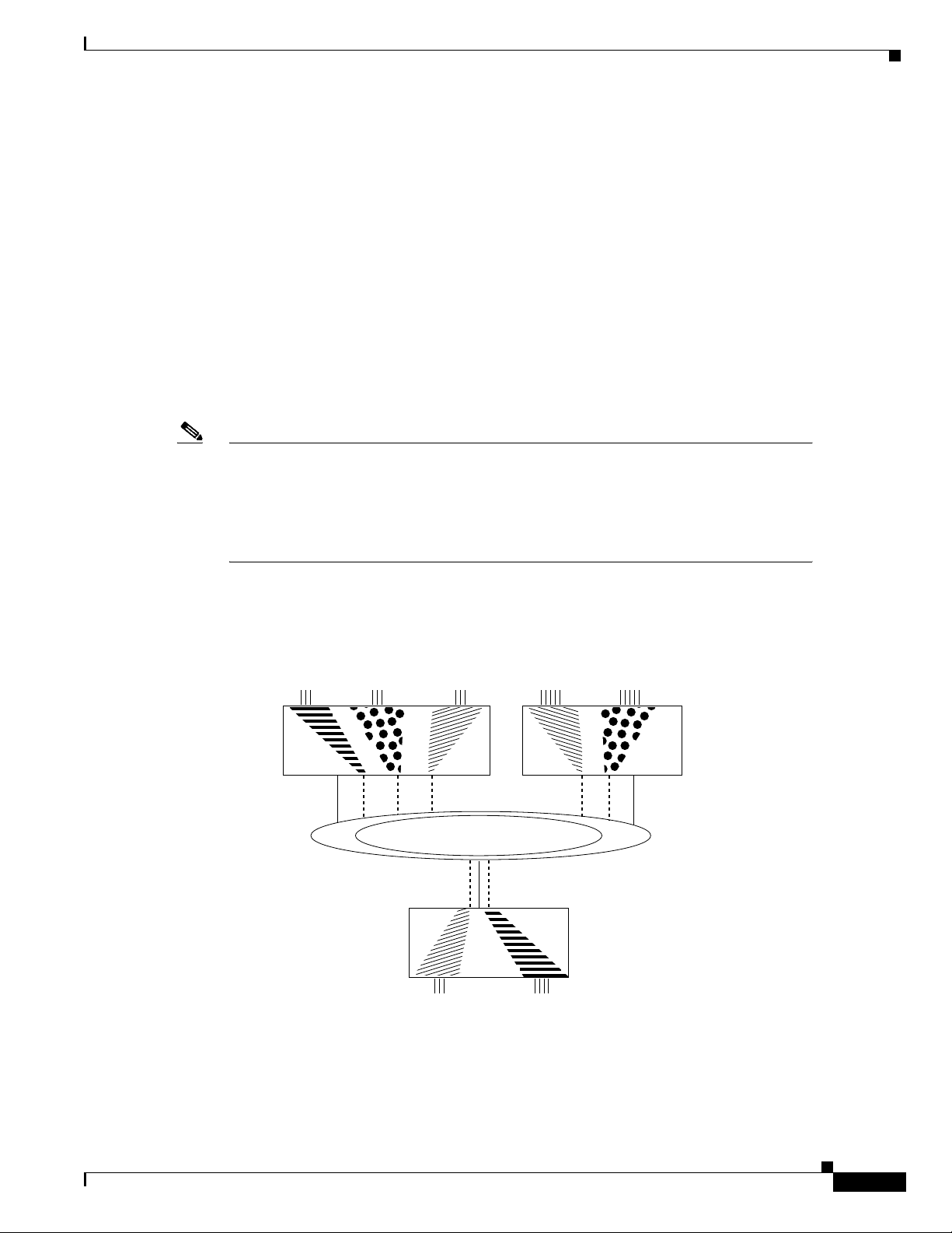
In Figure 9, different bridge groups on different routers are configured into three VLANs that span the
bridged network. Each bridge group consists of conventionally bridged local interfaces and a
subinterface on the backbone FDDI LAN. Bridged traffic on the subinterface is encapsulated and
“colored” with a VLAN identifier known as a security association identifier common to all bridge
groups participating in the VLAN. In addition, bridges only accept packets bearing security association
identifiers for which they have a configured subinterface. Thus, a bridge group is configured to
participate in a VLAN if it contains a subinterface configured with the VLAN’s characteristic security
association identifier. See the “Complex Integrated Routing and Bridging Example” section on page 66
for an example configuration of the topology shown in Figure 9.
Note The 802.10 encapsulation used to “color” transparently bridged packets on subinterfaces
might increase the size of a packet so that it exceeds the MTU size of the LAN from which
the packet originated. To avoid MTU violations on the shared network, the originating
LANs must either have a smaller native MTU than the shared network (as is the case from
Ethernet to FDDI), or the MTU on all packet sources on the originating LAN must be
configured to be at least 16 bytes less than the MTU of the shared network.
Transparent and SRT Bridging Configuration Task List
Figure 9 Transparently Bridged VLANs on an FDDI Backbone
Bridge
group 18
"Striped"
packets
Router 1 Router 2
Shared network
Bridge
group 54
"Dot"
packets
"Striped"
packets
Bridge
group 1
"Sliced"
packets
Bridge
group 3
"Sliced"
packets
"Dot"
packets
Bridge
group 7
"Sliced"
packets
"Sliced"
packets
Bridge
group 6
"Striped"
packets
Bridge
group 8
"Dot"
packets
Router 3
S3228
Cisco IOS Bridging and IBM Networking Configuration Guide
BC-31
Page 10

Transparent and SRT Bridging Configuration Task List
To configure a VLAN on a transparently bridged network, use the following commands beginning in
global configuration mode:
Command Purpose
Step 1
Step 2
Step 3
interface type
slot/port.subinterface-number
encapsulation sde said
bridge-group bridge-group
Transparently bridged VLANs are supported in conjunction with only the IEEE Spanning-Tree Protocol.
When you logically segment a transparently bridged network into VLANs, each VLAN computes its
own spanning-tree topology. Configuring each VLAN to compute its own spanning-tree topology
provides much greater stability than running a single spanning tree throughout. Traffic bridged within
one VLAN is unaffected by physical topology changes occurring within another VLAN.
Note The current implementation of SDE encapsulation is not recommended for serial or
Ethernet media.
Configuring Transparent Bridging
Specifies a subinterface.
Specifies the IEEE 802.10 Security data exchange security association
identifier (in other words, specifies the “color”).
Associates the subinterface with an existing bridge group.
Routing between ISL VLANs
Our VLAN Routing implementation is designed to operate across all router platforms. However, the
Inter-Switch Link (ISL) VLAN trunking protocol currently is defined on 100 BaseTX/FX Fast Ethernet
interfaces only and therefore is appropriate to the Cisco 7000 and higher-end platforms only. The IEEE
802.10 protocol can run over any LAN or HDLC serial interface. VLAN traffic is fast switched. The
actual format of these VLAN encapsulations are detailed in the IEEE Standard 802.10-1992 Secure Data
Exchange and in the Inter-Switch Link (ISL) Protocol Specification.
Our VLAN Routing implementation treats the ISL and 802.10 protocols as encapsulation types. On a
physical router interface that receives and transmits VLAN packets, you can select an arbitrary
subinterface and map it to the particular VLAN “color” embedded within the VLAN header. This
mapping allows you to selectively control how LAN traffic is routed or switched outside of its own
VLAN domain. In the VLAN routing paradigm, a switched VLAN corresponds to a single routed subnet,
and the network address is assigned to the subinterface.
To route a received VLAN packet the Cisco IOS software VLAN switching code first extracts the VLAN
ID from the packet header (this is a 10-bit field in the case of ISL and a 4-byte entity known as the
security association identifier in the case of IEEE 802.10), then demultiplexes the VLAN ID value into
a subinterface of the receiving port. If the VLAN color does not resolve to a subinterface, the Cisco IOS
software can transparently bridge the foreign packet natively (without modifying the VLAN header) on
the condition that the Cisco IOS software is configured to bridge on the subinterface itself. For VLAN
packets that bear an ID corresponding to a configured subinterface, received packets are then classified
by protocol type before running the appropriate protocol specific fast switching engine. If the
subinterface is assigned to a bridge group then non-routed packets are de-encapsulated before they are
bridged. This is termed “fall-back bridging” and is most appropriate for nonroutable traffic types.
BC-32
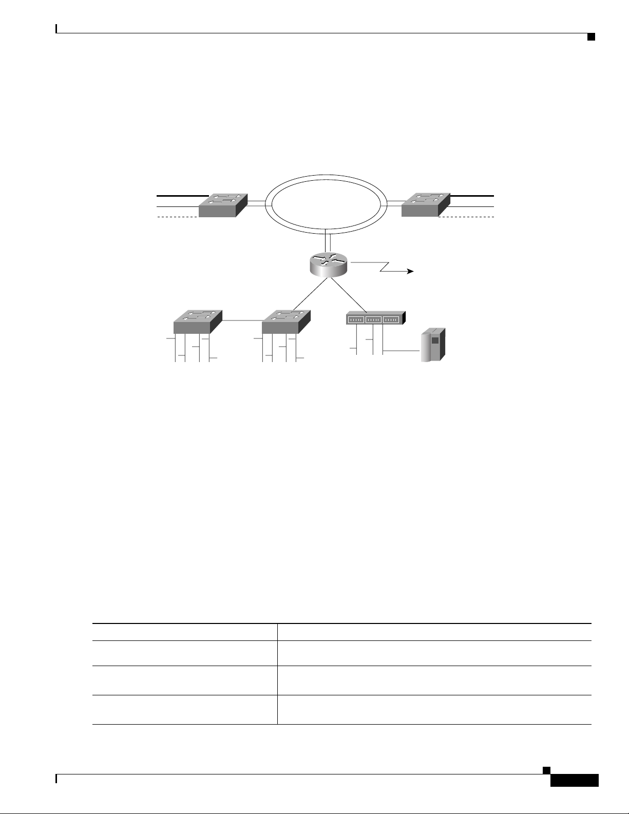
In Figure 10, Router A provides inter-VLAN connectivity between multiple Cisco switching platforms
where there are three distinct virtual topologies present. For example, for VLAN 300 across the two
Catalyst 1200A segments, traffic originating on LAN interface 1 is “tagged” with a VLAN ID of 300 as
it is switched onto the FDDI ring. This ID allows the remote Catalyst 1200A to make an intelligent
Cisco IOS Bridging and IBM Networking Configuration Guide
Page 11
Configuring Transparent Bridging
forwarding decision and only switch the traffic to local interfaces configured as belonging to the same
VLAN broadcast domain. Router A provides an inter-VLAN mechanism that lets Router A function as
a gateway for stations on a given LAN segment by transmitting VLAN encapsulated traffic to and from
other switched VLAN domains or simply transmitting traffic in native (non-VLAN) format.
Figure 10 Inter-VLAN Connectivity between Multiple Switching Platforms
Transparent and SRT Bridging Configuration Task List
VLAN100
1
VLAN200
2
VLAN300
3
Catalyst 1200A Catalyst 1200B
100BT ISL
VLAN400 VLAN500 VLAN400 VLAN500
802.10 FDDI VLAN
Backbone
Router A
2/1
1/1
3/1
100BT ISL
VLAN400 VLAN600
Wide area link
ProStack
Mainframe
VLAN100
VLAN200
VLAN300
S3902
1
2
3
Figure 10 illustrates the following scenarios:
• Clients on VLAN 300 want to establish sessions with a server attached to a port in a different VLAN
(600). In this scenario, packets originating on LAN interface 3 of the Catalyst 1200B switch are
tagged with an 802.10 header with a security association identifier of 300 as they are forwarded onto
the FDDI ring. Router A can accept these packets because it is configured to route VLAN 300,
classify and make a layer 3 forwarding decision based on the destination network address and the
route out (in this case Fast Ethernet 3/1), and adding the ISL VLAN header (color 200) appropriate
to the destination subnet as the traffic is switched.
Step 1
Step 2
Step 3
• There is a network requirement to bridge two VLANs together through the system rather than
selectively route certain protocols. In this scenario the two VLAN IDs are placed in the same bridge
group. Note that they form a single broadcast domain and spanning tree, effectively forming a single
VLAN.
See the “Routing between VLANs Configuration Example” section on page 70 for an example
configuration of the topology shown in Figure 10.
To configure bridging between VLANs, enter the following commands, beginning in interface
configuration mode:
Command Purpose
interface type
slot/port.subinterface-number
encapsulation {sde | isl} domain
Specifies a subinterface.
Specifies the encapsulation type (either ISL or SDE) and associates the
subinterface with the VLAN.
bridge-group bridge-group
Enables bridged traffic between the subinterface and other interfaces in
the same bridge group.
Cisco IOS Bridging and IBM Networking Configuration Guide
BC-33
Page 12

Transparent and SRT Bridging Configuration Task List
Configuring a Subscriber Bridge Group
The Digital Subscriber Line (xDSL) bridge support feature enables you to configure a router for
intelligent bridge flooding for xDSL and other bridge applications. To configure a subscriber bridge
group, use the following commands, beginning in global configuration mode:
Command Purpose
Step 1
Step 2
Step 3
Step 4
Step 5
bridge bridge-group protocol {ieee |
dec | vlan-bridge}
bridge bridge-group subscriber-policy
policy
subscriber-policy policy [[no]
[default] packet [permit] [deny]]
interface type number
bridge-group bridge-group
[subscriber-trunk]
Defines the bridge Spanning-Tree Protocol.
Defines a subscriber bridge group and specifies the subscriber policy
for the group.
Defines or modifies the forward and filter decisions of the subscriber
policy.
Configures a subinterface.
Assigns a subscriber bridge group and indicates whether the
interface is upstream or downstream from the traffic flow.
Configuring Transparent Bridging
Note Standard access lists can coexist with the subscriber policy. However, subscriber policy
will take precedence over the access list by being checked first. A packet permitted by the
subscriber policy will be checked against the access list if it is specified. A packet denied
by subscriber policy will be dropped with no further access list checking.
Configuring Transparent Bridging over WANs
You can configure transparent bridging over a variety of networks, as described in the following sections:
• Configuring Fast-Switched Transparent Bridging over ATM, page 34
• Configuring Transparent Bridging over DDR, page 35
• Configuring Transparent Bridging over Frame Relay, page 36
• Configuring Transparent Bridging over Multiprotocol LAPB, page 37
• Configuring Transparent Bridging over SMDS, page 38
• Configuring Transparent Bridging over X.25, page 38
Configuring Fast-Switched Transparent Bridging over ATM
Our bridging implementation supports IEEE 802.3 frame formats and IEEE 802.10 frame formats. Our
implementation can transparently bridge ARPA style Ethernet packets (also known as Ethernet version
2).
Fast-switched transparent bridging over Asynchronous Transfer Mode (ATM) supports AAL5-SNAP
encapsulated packets only. All bridged AAL5-SNAP encapsulated packets are fast switched.
Fast-switched transparent bridging supports Ethernet, FDDI, and Token Ring packets sent in
AAL5-SNAP encapsulation over ATM. See the section “Fast-Switched Transparent Bridging over ATM
Example (Cisco 7000)” for an example configuration of fast-switched transparent bridging over ATM.
BC-34
Cisco IOS Bridging and IBM Networking Configuration Guide
Page 13

Configuring Transparent Bridging
Support for RFC 1483 was added in Cisco IOS Release 12.0(3)T, enabling transparent bridging between
Token Ring LANs (using AAL5-SNAP PVCs) and LANs, VLANs or ELANS (using bridged PDUs).
RFC 1483 defines an encapsulation type for transferring LAN data via ATM networks.
For more information on configuring ATM, refer to the “Configuring ATM” chapter in the Cisco IOS
Wide-Area Networking Configuration Guide.
Configuring Transparent Bridging over DDR
The Cisco IOS software supports transparent bridging over dial-on-demand routing (DDR) and provides
you some flexibility in controlling access and configuring the interface.
To configure DDR for bridging, complete the tasks in the following sections:
• Defining the Protocols to Bridge
• Specifying the Bridging Protocol
• Determining Access for Bridging
• Configuring an Interface for Bridging
For an example of configuring transparent bridging over DDR, see the section “Transparent Bridging
over DDR Examples” section.
Transparent and SRT Bridging Configuration Task List
Defining the Protocols to Bridge
IP packets are routed by default unless they are explicitly bridged; all others are bridged by default unless
they are explicitly routed.
To bridge IP packets, use the following command in global configuration mode:
Command Purpose
no ip routing
Disables IP routing.
If you choose not to bridge another protocol, use the relevant command to enable routing of that protocol.
For more information about tasks and commands, refer to the relevant protocol chapters in the following
publications:
• Cisco IOS IP and IP Routing Configuration Guide
• Cisco IOS AppleTalk and Novell IPX Configuration Guide
• Cisco IOS Apollo Domain, Banyan VINES, DECnet, ISO CLNS, and XNS Configuration Guide
Specifying the Bridging Protocol
You must specify the type of spanning-tree bridging protocol to use and also identify a bridge group. To
specify the Spanning-Tree Protocol and a bridge group number, use the following command in global
configuration mode:
Command Purpose
bridge bridge-group protocol {ieee | dec |
vlan-bridge}
Defines the type of spanning tree protocol and identify a bridge group.
The bridge-group number is used when you configure the interface and assign it to a bridge group.
Packets are bridged only among members of the same bridge group.
Cisco IOS Bridging and IBM Networking Configuration Guide
BC-35
Page 14

Transparent and SRT Bridging Configuration Task List
Determining Access for Bridging
You can determine access by either permitting all bridge packets or by controlling access according to
Ethernet type codes.
To permit all transparent bridge packets, use the following command in global configuration mode:
Command Purpose
dialer-list dialer-group protocol bridge
permit
Defines a dialer list that permits all transparent bridge packets.
To control access by Ethernet type codes, use the following commands in global configuration mode:
Command Purpose
Step 1
Step 2
access-list access-list-number
{permit | deny} type-code [mask]
dialer-list dialer-group protocol
bridge list access-list-number
Permits packets according to Ethernet type codes (access list numbers
must be in the range 200 to 299).
Defines a dialer list for the specified access list.
Configuring Transparent Bridging
For a table of some common Ethernet types codes, see the “Ethernet Types Codes” appendix in the
Cisco IOS Bridging and IBM Networking Command Reference, Volume I.
Configuring an Interface for Bridging
You can configure serial interfaces or ISDN interfaces for DDR bridging. To configure an interface for
DDR bridging, use the following commands beginning in global configuration mode:
Command Purpose
Step 1
interface type number
Specifies the serial or ISDN interface and enter interface
configuration mode.
Step 2
Step 3
dialer string dial-string
dialer map bridge [name
[broadcast]dial-string[:isdn-subaddress]
bridge-group bridge-group
hostname]
Configures the dial string to call.
or
Configures a dialer bridge map.
Assigns the specified interface to a bridge group.
Configuring Transparent Bridging over Frame Relay
The transparent bridging software supports bridging of packets over Frame Relay networks. This ability
is useful for such tasks as transmitting packets from proprietary protocols across a Frame Relay network.
Bridging over a Frame Relay network is supported both on networks that support a multicast facility and
those that do not. Both cases are described in this section.
BC-36
Fast-Switched Transparent Bridging
The transparent bridging software provides fast-switched transparent bridging for Frame Relay
encapsulated serial and High-Speed Serial Interface (HSSI) networks.
Switched virtual circuits (SVCs) are not supported for transparent bridging in this release. All the
Permanent virtual circuits (PVCs) configured on a subinterface must belong to the same bridge group.
Cisco IOS Bridging and IBM Networking Configuration Guide
Page 15

Configuring Transparent Bridging
Bridging in a Frame Relay Network with No Multicasts
The Frame Relay bridging software uses the same spanning-tree algorithm as the other bridging
functions, but allows packets to be encapsulated for transmission across a Frame Relay network. You
specify IP-to-data-link connection identifier (DLCI) address mapping and the system maintains a table
of both the Ethernet address and the DLCIs.
To configure bridging in a network that does not support a multicast facility, define the mapping between
an address and the DLCI used to connect to the address. To bridge with no multicasts, use the following
command in interface configuration mode:
Command Purpose
frame-relay map bridge dlci broadcast
Defines the mapping between an address and the DLCI used to
connect to the address.
An example configuration is provided in the section “Frame Relay Transparent Bridging Examples” at
the end of this chapter. Frame Relay is discussed in more detail in the “Configuring Frame Relay”
chapter in the Cisco IOS Wide-Area Networking Configuration Guide.
Bridging in a Frame Relay Network with Multicasts
The multicast facility is used to learn about the other bridges on the network, eliminating the need for
you to specify any mappings with the frame-relay map bridge broadcast command. An example
configuration is provided in the section “Frame Relay Transparent Bridging Examples” at the end of the
chapter for use as a configuration guide. Frame Relay is discussed in more detail in the “Configuring
Frame Relay” chapter in the Cisco IOS Wide-Area Networking Configuration Guide.
Transparent and SRT Bridging Configuration Task List
Configuring Transparent Bridging over Multiprotocol LAPB
Cisco IOS software implements transparent bridging over multiprotocol Link Access Protocol-Balanced
(LAPB) encapsulation on serial interfaces. To configure transparent bridging over multiprotocol LAPB,
use the following commands beginning in global configuration mode:
Command Purpose
Step 1
Step 2
Step 3
Step 4
Step 5
interface serial number
no ip address
encapsulation lapb multi
bridge-group bridge-group
bridge bridge-group protocol {ieee | dec | vlan-bridge}
Note Transparent bridging over multiprotocol LAPB requires use of the encapsulation lapb
multi command. You cannot use the encapsulation lapb
keyword to configure this feature.
For an example of configuring transparent bridging over multiprotocol LAPB, see the
“Transparent Bridging over Multiprotocol LAPB Example” section on page 76”.
Specifies the serial interface.
Specifies no IP address to the interface.
Configures multiprotocol LAPB encapsulation.
Assigns the interface to a bridge group.
Specifies the type of Spanning-Tree Protocol.
protocol command with a bridge
Cisco IOS Bridging and IBM Networking Configuration Guide
BC-37
Page 16

Transparent and SRT Bridging Configuration Task List
Configuring Transparent Bridging over SMDS
We support fast-switched transparent bridging for Switched Multimegabit Data Service (SMDS)
encapsulated serial and HSSI networks. Standard bridging commands are used to enable bridging on an
SMDS interface.
To enable transparent bridging over SMDS, use the following commands beginning in global
configuration mode:
Command Purpose
Step 1
Step 2
Step 3
Step 4
interface serial number
encapsulation smds
bridge-group bridge-group
smds multicast bridge smds-address
Broadcast Address Resolution Protocol (ARP) packets are treated differently in transparent bridging
over an SMDS network than in other encapsulation methods. For SMDS, two packets are sent to the
multicast address. One is sent using a standard (SMDS) ARP encapsulation; the other is sent with the
ARP packet encapsulated in an 802.3 MAC header. The native ARP is sent as a regular ARP broadcast.
Our implementation of IEEE 802.6i transparent bridging for SMDS supports 802.3, 802.5, and FDDI
frame formats. The router can accept frames with or without frame check sequence (FCS). Fast-switched
transparent bridging is the default and is not configurable. If a packet cannot be fast switched, it is
process switched.
An example configuration is provided in the section “Fast-Switched Transparent Bridging over SMDS
Example” later in this chapter. For more information on SMDS, refer to the “Configuring SMDS”
chapter in the Cisco IOS Wide-Area Networking Configuration Guide.
Specifies the serial interface.
Configures SMDS encapsulation on the serial interface.
Associates the interface with a bridge group.
Enables transparent bridging of packets across an SMDS network.
Configuring Transparent Bridging
Configuring Transparent Bridging over X.25
The transparent bridging software supports bridging of packets in X.25 frames. This ability is useful for
such tasks as transmitting packets from proprietary protocols across an X.25 network.
The X.25 bridging software uses the same spanning-tree algorithm as the other bridging functions, but
allows packets to be encapsulated in X.25 frames and transmitted across X.25 media. You specify the
IP-to-X.121 address mapping, and the system maintains a table of both the Ethernet and X.121
addresses. To configure X.25 transparent bridging, use the following command in interface
configuration mode:
Command Purpose
x25 map bridge x.121-address broadcast
[options-keywords]
For more information about configuring X.25, refer to the “Configuring X.25 and LAPB” chapter in the
Cisco IOS Wide-Area Networking Configuration Guide.
Specifies IP-to-X.121 mapping.
BC-38
Cisco IOS Bridging and IBM Networking Configuration Guide
Page 17

Configuring Transparent Bridging
Configuring Concurrent Routing and Bridging
You can configure the Cisco IOS software to route a given protocol among one group of interfaces and
concurrently bridge that protocol among a separate group of interfaces, all within one router. The given
protocol is not switched between the two groups. Rather, routed traffic is confined to the routed
interfaces and bridged traffic is confined to the bridged interfaces. A protocol may be either routed or
bridged on a given interface, but not both.
The concurrent routing and bridging capability is, by default, disabled. While concurrent routing and
bridging is disabled, the Cisco IOS software absorbs and discards bridgeable packets in protocols that
are configured for routing on any interface in the router.
When concurrent routing and bridging is first enabled in the presence of existing bridge groups, it will
generate a bridge route configuration command for any protocol for which any interface in the bridge
group is configured for routing. This is a precaution that applies only when concurrent routing and
bridging is not already enabled, bridge groups exist, and the bridge crb command is encountered.
To enable concurrent routing and bridging in the Cisco IOS software, use the following command in
global configuration mode:
Command Purpose
bridge crb
Enables concurrent routing and bridging.
Transparent and SRT Bridging Configuration Task List
Information about which protocols are routed and which are bridged is stored in a table, which can be
displayed with the show interfaces crb privileged EXEC command.
When concurrent routing and bridging has been enabled, you must configure an explicit bridge route
command for any protocol that is to be routed on the interfaces in a bridge group in addition to any
required protocol-specific interface configuration.
To configure specific protocols to be routed in a bridge group, use the following command in interface
configuration mode:
Command Purpose
bridge bridge-group route protocol
Specifies a protocol to be routed on a bridge group.
Configuring Integrated Routing and Bridging
Perform one or more of the following tasks to configure integrated routing and bridging on your router:
• Assigning a Bridge Group Number and Defining the Spanning-Tree Protocol
• Configuring Interfaces
• Enabling Integrated Routing and Bridging
• Configuring the Bridge-Group Virtual Interface
• Configuring Protocols for Routing or Bridging
Cisco IOS Bridging and IBM Networking Configuration Guide
BC-39
Page 18

Transparent and SRT Bridging Configuration Task List
Assigning a Bridge Group Number and Defining the Spanning-Tree Protocol
Prior to configuring the router for integrated routing and bridging, you must enable bridging by setting
up a bridge group number and specifying a Spanning-Tree Protocol. You can choose either the IEEE
802.1D Spanning-Tree Protocol or the earlier Digital protocol upon which this IEEE standard is based.
To assign a bridge group number and define a spanning tree protocol, use the following command in
global configuration mode:
Command Purpose
bridge bridge-group protocol {ieee | dec |
vlan-bridge}
Assigns a bridge group number and defines a Spanning-Tree Protocol.
The IEEE 802.1D Spanning-Tree Protocol is the preferred way of running the bridge. Use the Digital
Spanning-Tree Protocol only for backward compatibility.
Configuring Interfaces
To configure a router interface in the Cisco IOS software, use the following commands beginning in
global configuration mode:
Configuring Transparent Bridging
Command Purpose
Step 1
Step 2
Step 3
interface type number
port
bridge-group bridge-group
Specifies the interface and enters interface configuration mode.
Specifies concentrator port operation.
Assigns bridge-groups to appropriate interfaces.
Enabling Integrated Routing and Bridging
After you have set up the interfaces in the router, you can enable integrated routing and bridging.
To enable integrated routing and bridging in the Cisco IOS software, use the following command in
global configuration mode:
Command Purpose
bridge irb
Enables integrated routing and bridging.
Use the show interfaces irb privileged EXEC command to display the protocols that a given bridged
interface can route to the other routed interface when the packet is routable, and to display the protocols
that a given bridged interface bridges.
Configuring the Bridge-Group Virtual Interface
The bridge-group virtual interface resides in the router. It acts like a normal routed interface that does
not support bridging, but represents the entire corresponding bridge group to routed interfaces within the
router. The bridge-group virtual interface is assigned the number of the bridge group that it represents.
The bridge-group virtual interface number is the link between the bridge-group virtual interface and its
bridge group. Because the bridge-group virtual interface is a virtual routed interface, it has all the
network layer attributes, such as a network address and the ability to perform filtering. Only one
bridge-group virtual interface is supported for each bridge group.
BC-40
Cisco IOS Bridging and IBM Networking Configuration Guide
Page 19

Configuring Transparent Bridging
When you enable routing for a given protocol on the bridge-group virtual interface, packets coming from
a routed interface but destined for a host in a bridged domain are routed to the bridge-group virtual
interface, and are forwarded to the corresponding bridged interface. All traffic routed to the bridge-group
virtual interface is forwarded to the corresponding bridge group as bridged traffic. All routable traffic
received on a bridged interface is routed to other routed interfaces as if it is coming directly from the
bridge-group virtual interface.
To create a bridge-group virtual interface, use the following command in interface configuration mode:
Command Purpose
interface bvi bridge-group
Enables a bridge-group virtual interface.
When you intend to bridge and route a given protocol in the same bridge group, you must configure the
network-layer attributes of the protocol on the bridge-group virtual interface. Do not configure protocol
attributes on the bridged interfaces. No bridging attributes can be configured on the bridge-group virtual
interface.
Although it is generally the case that all bridged segments belonging to a bridge group are represented
as a single segment or network to the routing protocol, there are situations where several individual
networks coexist within the same bridged segment. To make it possible for the routed domain to learn
about the other networks behind the bridge-group virtual interface, configure a secondary address on the
bridge-group virtual interface to add the corresponding network to the routing process.
Transparent and SRT Bridging Configuration Task List
Configuring Protocols for Routing or Bridging
When integrated routing and bridging is enabled, the default route/bridge behavior in a bridge group is
to bridge all packets.
You could then explicitly configure the bridge group to route a particular protocol, so that routable
packets of this protocol are routed, while nonroutable packets of this protocol or packets for protocols
for which the bridge group is not explicitly configured to route will be bridged.
You could also explicitly configure the bridge group so that it does not bridge a particular protocol, so
that routable packets of this protocol are routed when the bridge is explicitly configured to route this
protocol, and nonroutable packets are dropped because bridging is disabled for this protocol.
Note Packets of nonroutable protocols such as LAT are only bridged. You cannot disable
bridging for the nonroutable traffic.
To configure specific protocols to be routed or bridged in a bridge group, use one or more of the
following commands in global configuration mode:
Command Purpose
bridge bridge-group route protocol
no bridge bridge-group route protocol
bridge bridge-group bridge protocol
no bridge bridge-group bridge protocol
Specifies a protocol to be routed in a bridge group.
Specifies that a protocol is not to be routed in a bridge group.
Specifies that a protocol is to be bridged in the bridge group.
Specifies that a protocol is not to be bridged in the bridge group.
Cisco IOS Bridging and IBM Networking Configuration Guide
BC-41
Page 20

Transparent and SRT Bridging Configuration Task List
Note When a bridge group contains Token Ring interfaces, the Token Ring packets must not
include RIF. The IEEE 802.1d transparent bridge standard specifies that frames with source
routing information are to be dropped by transparent bridges; therefore, if Token Ring
traffic includes RIF, it will be dropped. RIF is designated by the RII, which is the first bit
of the MAC address. RII=1 indicates that the packet comes with RIF, RII=0 indicates that
the frame does not come with RIF.
For example, to bridge AppleTalk, bridge and route IPX, and route IP in the same bridge group, you
would do the following:
• Bridge AppleTalk—Because integrated routing and bridging bridges everything by default, no
configuration is required to bridge AppleTalk.
• Bridge and route IPX—After using the bridge irb command to enable integrated routing and
bridging, and the interface bvi command to create the bridge-group virtual interface for the bridge
group, you would use the bridge route command to both bridge and route IPX (bridging is already
enabled by default; the bridge route command enables routing).
• Route IP—Use the bridge route command to enable routing, and then use the no bridge bridge
command to disable bridging.
Configuring Transparent Bridging
Note When integrated routing and bridging is not enabled, routing a given protocol means that
protocol is not bridged, and bridging a protocol means that protocol is not routed. When
integrated routing and bridging is enabled, the disjunct relationship between routing and
bridging is broken down, and a given protocol can be switched between routed and bridged
interfaces on a selective, independent basis.
Configuring Transparent Bridging Options
You can configure one or more transparent bridging options. To configure transparent bridging options,
perform one or more of the tasks in the following sections:
• Disabling IP Routing, page 42
• Enabling Autonomous Bridging, page 43
• Configuring LAT Compression, page 43
• Establishing Multiple Spanning-Tree Domains, page 44
• Preventing the Forwarding of Dynamically Determined Stations, page 45
• Forwarding Multicast Addresses, page 45
• Configuring Bridge Table Aging Time, page 45
Disabling IP Routing
BC-42
If you want to bridge IP, you must disable IP routing because IP routing is enabled by default on the
Cisco IOS software. You can enable IP routing when you decide to route IP packets. To disable or enable
IP routing, use one of the following commands in global configuration mode:
Cisco IOS Bridging and IBM Networking Configuration Guide
Page 21

Configuring Transparent Bridging
Command Purpose
no ip routing
ip routing
Disables IP routing.
Enables IP routing.
All interfaces in the bridge group that are bridging IP should have the same IP address. However, if you
have more than one bridge group, each bridge group should have its own IP address.
Enabling Autonomous Bridging
Normally, bridging takes place on the processor card at the interrupt level. When autonomous bridging
is enabled, bridging takes place entirely on the ciscoBus2 controller, significantly improving
performance. Autonomous bridging is a high-speed switching feature that allows bridged traffic to be
forwarded and flooded on the ciscoBus2 controller between resident interfaces. If you are using the
ciscoBus2 controller, you can maximize performance by enabling autonomous bridging on the following
ciscoBus2 interfaces:
• MEC
Transparent and SRT Bridging Configuration Task List
• FCIT transparent
• HSSI HDLC
Although performance improvements will be seen most in the resident interfaces, the autonomous
bridging feature can also be used in bridge groups that include interfaces that are not on the ciscoBus2
controller. These interfaces include the CTR, FCI with encapsulation bridging, and HSSI with
encapsulation other than HDLC, such as X.25, Frame Relay, or SMDS, MCI, STR, or SBE16.
If you enable autonomous bridging for a bridge group that includes a combination of interfaces that are
resident on the ciscoBus2 controller and some that are not, the ciscoBus2 controller forwards only
packets between resident interfaces. Forwarding between nonresident and resident interfaces is done in
either the fast or process paths. Flooding between resident interfaces is done by the ciscoBus2 controller.
Flooding between nonresident interfaces is done conventionally. If a packet is forwarded from a
nonresident to a resident interface, the packet is conventionally forwarded. If packets are flooded from
a nonresident interface to a resident interface, the packet is autonomously flooded.
To enable autonomous bridging on a per-interface basis, use the following command in interface
configuration mode:
Command Purpose
bridge-group bridge-group cbus-bridging
Note You can filter by MAC-layer address on an interface only when autonomous bridging is
Enables autonomous bridging (if using the ciscoBus2 controller).
enabled on that interface. If any filters or priority queuing is configured, autonomous
bridging is automatically disabled.
Configuring LAT Compression
The local-area transport (LAT) protocol used by Digital and Digital-compatible terminal servers is one
of the common protocols that lacks a well-defined network layer (Layer 3) and so always must be
bridged.
Cisco IOS Bridging and IBM Networking Configuration Guide
BC-43
Page 22

Transparent and SRT Bridging Configuration Task List
To reduce the amount of bandwidth that LAT traffic consumes on serial interfaces, you can specify a
LAT-specific form of compression. Doing so applies compression to LAT frames being sent out by the
Cisco IOS software through the interface in question. To configure LAT compression, use the following
command in interface configuration mode:
Command Purpose
bridge-group bridge-group lat-compression
Reduces the amount of bandwidth that LAT traffic consumes on a
serial interface.
LAT compression can be specified only for serial interfaces. For the most common LAT operations (user
keystrokes and acknowledgment packets), LAT compression reduces LAT’s bandwidth requirements by
nearly a factor of two.
Establishing Multiple Spanning-Tree Domains
The Cisco IEEE 802.1D bridging software supports spanning-tree domains of bridge groups. Domains
are a feature specific to Cisco. This feature is only available if you have specified IEEE as the
Spanning-Tree Protocol. A domain establishes an external identification of the BPDUs sent from a
bridge group. The purpose of this identification is as follows:
Configuring Transparent Bridging
• Bridge groups defined within the domain can recognize that BPDU as belonging to them.
• Two bridged subnetworks in different domains that are sharing a common connection can use the
domain identifier to identify and then ignore the BPDUs that belong to another domain. Each
bridged subnetwork establishes its own spanning tree based on the BPDUs that it receives. The
BPDUs it receives must contain the domain number to which the bridged subnetwork belongs.
Bridged traffic is not domain identified.
Note Domains do not constrain the propagation of bridged traffic. A bridge bridges nonrouted
traffic received on its interfaces regardless of domain.
You can place any number of routers or bridges within the domain. Only the devices within a domain
share spanning-tree information.
When multiple routers share the same cable and you want to use only certain discrete subsets of those
routers to share spanning-tree information with each other, establish spanning-tree domains. This
function is most useful when running other applications, such as IP User Datagram Protocol (UDP)
flooding, that use the IEEE spanning tree. You also can use this feature to reduce the number of global
reconfigurations in large bridged networks.
To establish multiple spanning-tree domains, use the following command in global configuration mode:
Command Purpose
bridge bridge-group domain domain-number
Establishes a multiple spanning-tree domain.
BC-44
For an example of how to configure domains, see the “Complex Transparent Bridging Network Topology
Example” section later in this chapter.
Cisco IOS Bridging and IBM Networking Configuration Guide
Page 23

Configuring Transparent Bridging
Preventing the Forwarding of Dynamically Determined Stations
Normally, the system forwards any frames for stations that it has learned about dynamically. By
disabling this activity, the bridge will only forward frames whose address have been statically configured
into the forwarding cache. To prevent or allow forwarding of dynamically determined stations, use one
of the following command in global configuration mode:
Command Purpose
no bridge bridge-group acquire
bridge bridge-group acquire
Filters out all frames except those whose addresses have been
statically configured into the forwarding cache.
Removes the ability to filter out all frames except those whose
addresses have been statically configured into the forwarding cache.
Forwarding Multicast Addresses
A packet with a RIF, indicated by a source address with the multicast bit turned on, is not usually
forwarded. However, you can configure bridging support to allow the forwarding of frames that would
otherwise be discarded because they have a RIF. Although you can forward these frames, the bridge table
will not be updated to include the source addresses of these frames.
To forward frames with multicast addresses, use the following command in global configuration mode:
Transparent and SRT Bridging Configuration Task List
Command Purpose
bridge bridge-group multicast-source
Allows the forwarding of frames with multicast source addresses.
Configuring Bridge Table Aging Time
A bridge forwards, floods, or drops packets based on the bridge table. The bridge table maintains both
static entries and dynamic entries. Static entries are entered by the network manager or by the bridge
itself. Dynamic entries are entered by the bridge learning process. A dynamic entry is automatically
removed after a specified length of time, known as aging time, from the time the entry was created or
last updated.
If hosts on a bridged network are likely to move, decrease the aging-time to enable the bridge to adapt
to the change quickly. If hosts do not transmit continuously, increase the aging time to record the
dynamic entries for a longer time and thus reduce the possibility of flooding when the hosts transmit
again.
To set the aging time, use the following command in global configuration mode:
Command Purpose
bridge-group bridge-group aging-time seconds
Sets the bridge table aging time.
Filtering Transparently Bridged Packets
A bridge examines frames and transmits them through the internetwork according to the destination
address; a bridge will not forward a frame back to its originating network segment. The bridge software
allows you to configure specific administrative filters that filter frames based upon information other
than paths to their destinations. You can perform administrative filtering by performing one of the tasks
in the following sections:
Cisco IOS Bridging and IBM Networking Configuration Guide
BC-45
Page 24

Transparent and SRT Bridging Configuration Task List
• Setting Filters at the MAC Layer, page 46
• Filtering LAT Service Announcements, page 51
Note When setting up administrative filtering, remember that there is virtually no performance
penalty in filtering by Media Access Control (MAC) address or vendor code, but there can
be a significant performance penalty when filtering by protocol type.
When configuring transparent bridging access control, keep the following points in mind:
• You can assign only one access list to an interface.
• The conditions in the access list are applied to all outgoing packets not sourced by the Cisco IOS
software.
• Access lists are scanned in the order you enter them; the first match is used.
• An implicit deny everything entry is automatically defined at the end of an access list unless you
include an explicit permit everything entry at the end of the list.
• All new entries to an existing list are placed at the end of the list. You cannot add an entry to the
middle of a list. This means that if you have previously included an explicit permit everything entry,
new entries will never be scanned. The solution is to delete the access list and retype it with the new
entries.
• You can create extended access lists to specify more detailed filters, such as address match only.
• You should not use extended access lists on FDDI interfaces doing transit bridging as opposed to
translational bridging.
Configuring Transparent Bridging
• Configuring bridging access lists of type 700 may cause a momentary interruption of traffic flow.
For more information on access lists, refer to the “Traffic Filtering and Firewalls” chapter of the Cisco
IOS Security Configuration Guide.
Setting Filters at the MAC Layer
You can filter transmission of frames at the MAC layer by performing tasks in one of the following
sections:
• Filtering by Specific MAC Address
• Filtering by Vendor Code
• Filtering by Protocol Type
When filtering by a MAC-layer address, you can use two kinds of access lists: standard access lists that
specify a simple address, and extended access lists that specify two addresses. You can also further
restrict access by creating filters for these lists. After you have completed one of the preceding tasks,
perform the task in the following section:
• Defining and Applying Extended Access Lists
Note MAC addresses on Ethernets are “bit swapped” when compared with MAC addresses on
TokenRing and FDDI. For example, address 0110.2222.3333 on Ethernet is
8008.4444.CCCC on Token Ring and FDDI. Access lists always use the canonical Ethernet
representation. When using different media and building access lists to filter on MAC
addresses, keep this point in mind. Note that when a bridged packet traverses a serial link,
it has an Ethernet-style address.
BC-46
Cisco IOS Bridging and IBM Networking Configuration Guide
Page 25

Configuring Transparent Bridging
Transparent and SRT Bridging Configuration Task List
Filtering by Specific MAC Address
You can filter frames with a particular MAC-layer station source or destination address. Any number of
addresses can be configured into the system without a performance penalty. To filter by MAC-layer
address, use the following command in global configuration mode:
Command Purpose
bridge bridge-group address mac-address {forward |
discard}[interface]
When filtering specific MAC destination addresses, allow for multicast or broadcast packets that are
required by the bridged network protocols. Refer to the example in the section “Multicast or Broadcast
Packets Bridging Example” later in this chapter to guide you in building your configuration to allow for
multicast or broadcast packets.
Filtering by Vendor Code
The bridging software allows you to create access lists to administratively filter MAC addresses. These
access lists can filter groups of MAC addresses, including those with particular vendor codes. There is
no noticeable performance loss in using these access lists, and the lists can be of indefinite length. You
can filter groups of MAC addresses with particular vendor codes by performing the first task and one or
both of the other tasks that follow:
• Establish a vendor code access list
Filters particular MAC-layer station addresses.
• Filter source addresses
• Filter destination addresses
To establish a vendor code access list, use the following command in global configuration mode:
Command Purpose
access-list access-list-number {permit |
deny}
address mask
Prepares access control information for filtering of frames by canonical
(Ethernet-ordered) MAC address.
The vendor code is the first three bytes of the MAC address (left to right). For an example of how to filter
by vendor code, see “Multicast or Broadcast Packets Bridging Example” later in this chapter.
Note Remember that, as with any access list using MAC addresses, Ethernets swap their MAC
address bit ordering, and Token Rings and FDDI do not. Therefore, an access list that works
for one medium might not work for others.
Once you have defined an access list to filter by a particular vendor code, you can assign an access list
to a particular interface for filtering on the MAC source addresses of packets received on that interface
or the MAC destination addresses of packets that would ordinarily be forwarded out that interface. To
filter by source or destination addresses, use one of the following commands in interface configuration
mode:
Cisco IOS Bridging and IBM Networking Configuration Guide
BC-47
Page 26

Transparent and SRT Bridging Configuration Task List
Command Purpose
bridge-group bridge-group input-address-list
access-list-number
bridge-group bridge-group
output-address-list access-list-number
Assigns an access list to an interface for filtering by MAC source
addresses.
Assigns an access list to an interface for filtering by the MAC
destination addresses.
Filtering by Protocol Type
You can filter by protocol type by using the access-list mechanism and specifying a protocol type code.
To filter by protocol type, perform the first task and one or more of the other tasks that follow:
• Establish a protocol type access list
• Filter Ethernet- and SNAP-encapsulated packets on input
• Filter Ethernet- and SNAP-encapsulated packets on output
• Filter IEEE 802.2-encapsulated packets on input
• Filter IEEE 802.2-encapsulated packets on output
Configuring Transparent Bridging
Note It is a good idea to have both input and output type code filtering on different interfaces.
The order in which you enter access-list commands affects the order in which the access conditions are
checked. Each condition is tested in succession. A matching condition is then used to execute a permit
or deny decision. If no conditions match, a “deny” decision is reached.
Note Protocol type access lists can have an impact on system performance; therefore, keep the
lists as short as possible and use wildcard bit masks whenever possible.
Access lists for Ethernet- and IEEE 802.2-encapsulated packets affect only bridging functions. It is not
possible to use such access lists to block frames with protocols that are being routed.
You can establish protocol type access lists. Specify either an Ethernet type code for
Ethernet-encapsulated packets or a DSAP/SSAP pair for 802.3 or 802.5-encapsulated packets. Ethernet
type codes are listed in the “Ethernet Type Codes” appendix of the Cisco IOS Bridging and IBM
Networking Command Reference, Volume I.
To establish protocol type access lists, use the following command in global configuration mode:
Command Purpose
access-list access-list-number {permit |
deny} type-code wild-mask
Prepares access control information for filtering frames by protocol
type.
BC-48
You can filter Ethernet- and SNAP-encapsulated packets on input. For SNAP-encapsulated frames, the
access list you create is applied against the two-byte TYPE field given after the DSAP/SSAP/OUI fields
in the frame. The access list is applied to all Ethernet and SNAP frames received on that interface prior
to the bridge learning process. SNAP frames also must pass any applicable IEEE 802.2 DSAP/SSAP
access lists.
You can also filter Ethernet- and SNAP-encapsulated packets on output. The access list you create is
applied just before sending out a frame to an interface.
Cisco IOS Bridging and IBM Networking Configuration Guide
Page 27

Configuring Transparent Bridging
To filter these packets on input or output, use either or both of the following commands in interface
configuration mode:
Command Purpose
bridge-group bridge-group input-type-list
access-list-number
bridge-group bridge-group output-type-list
access-list-number
Adds a filter for Ethernet- and SNAP-encapsulated packets on input.
Adds a filter for Ethernet- and SNAP-encapsulated packets on output.
You can filter IEEE 802-encapsulated packets on input. The access list you create is applied to all IEEE
802 frames received on that interface prior to the bridge-learning process. SNAP frames also must pass
any applicable Ethernet type-code access list.
You can also filter IEEE 802-encapsulated packets on output. SNAP frames also must pass any
applicable Ethernet type-code access list. The access list you create is applied just before sending out a
frame to an interface.
To filter these packets on input or output, use one or both of the following commands in interface
configuration mode:
Transparent and SRT Bridging Configuration Task List
Command Purpose
bridge-group bridge-group input-lsap-list
access-list-number
bridge-group bridge-group output-lsap-list
access-list-number
Adds a filter for IEEE 802-encapsulated packets on input.
Adds a filter for IEEE 802-encapsulated packets on output.
Access lists for Ethernet- and IEEE 802-encapsulated packets affect only bridging functions. You cannot
use such access lists to block frames with protocols that are being routed.
Defining and Applying Extended Access Lists
If you are filtering by the MAC-layer address, whether it is by a specific MAC address, vendor code, or
protocol type, you can define and apply extended access lists. Extended access lists allow finer
granularity of control. They allow you to specify both source and destination addresses and arbitrary
bytes in the packet.
To define an extended access list, use the following command in global configuration mode:
Command Purpose
access-list access-list-number {permit |
deny}
source source-mask destination
destination-mask offset size operator operand
Defines an extended access list for finer control of bridged traffic.
To apply an extended access list to an interface, use one or both of the following commands in interface
configuration mode:
Command Purpose
bridge-group bridge-group input-pattern-list
access-list-number
bridge-group bridge-group output-pattern-list
access-list-number
Applies an extended access list to the packets being received by an
interface.
Applies an extended access list to the packet being sent by an
interface.
Cisco IOS Bridging and IBM Networking Configuration Guide
BC-49
Page 28

Transparent and SRT Bridging Configuration Task List
After an access list is created initially, any subsequent additions (possibly entered from the terminal) are
placed at the end of the list. In other words, you cannot selectively add or remove access list command
lines from a specific access list.
Caution Because of their complexity, only use extended access lists if you are very familiar with the
Cisco IOS software. Further, do not specify an offset value that is greater than the size of
the packet.
Configuring Transparent Bridging
BC-50
Cisco IOS Bridging and IBM Networking Configuration Guide
Page 29

Configuring Transparent Bridging
Filtering LAT Service Announcements
The bridging software allows you to filter LAT frames. LAT bridge filtering allows the selective
inclusion or exclusion of LAT multicast service announcements on a per-interface basis.
Note The LAT filtering commands are not implemented for Token Ring interfaces.
In the LAT protocol, a group code is defined as a decimal number in the range 0 to 255. Some of the LAT
configuration commands take a list of group codes; this is referred to as a group code list. The rules for
entering numbers in a group code list follow:
• Entries can be individual group code numbers separated with a space. (The Digital LAT
implementation specifies that a list of numbers be separated by commas; however, our
implementation expects the numbers to be separated by spaces.)
• Entries can also specify a range of numbers. This is done by separating an ascending order range of
group numbers with hyphens.
• Any number of group codes or group code ranges can be listed in one command; just separate each
with a space.
In LAT, each node transmits a periodic service advertisement message that announces its existence and
availability for connections. Within the message is a group code list; this is a mask of up to 256 bits.
Each bit represents a group number. In the traditional use of LAT group codes, a terminal server only
will connect to a host system when there is an overlap between the group code list of the user on the
terminal server and the group code list in the service advertisement message. In an environment with
many bridges and many LAT hosts, the number of multicast messages that each system has to deal with
becomes unreasonable. The 256 group codes might not be enough to allocate local assignment policies,
such as giving each DECserver 200 device its own group code in large bridged networks. LAT group
code filtering allows you to have very fine control over which multicast messages actually get bridged.
Through a combination of input and output permit and deny lists, you can implement many different LAT
control policies.
Transparent and SRT Bridging Configuration Task List
You can filter LAT service advertisements by performing any of the tasks in the following sections:
• Enabling LAT Group Code Service Filtering
• Specifying Deny or Permit Conditions for LAT Group Codes on Input
• Specifying Deny or Permit Conditions for LAT Group Codes on Output
Enabling LAT Group Code Service Filtering
You can specify LAT group-code filtering to inform the system that LAT service advertisements require
special processing. To enable LAT group-code filtering, use the following command in global
configuration mode:
Command Purpose
bridge bridge-group lat-service-filtering
Specifying Deny or Permit Conditions for LAT Group Codes on Input
Enables LAT service filtering.
You can specify the group codes by which to deny or permit access upon input. Specifying deny
conditions causes the system to not bridge any LAT service advertisement that contain any of the
specified groups. Specifying permit conditions causes the system to bridge only those service
advertisements that match at least one group in the specified group list.
Cisco IOS Bridging and IBM Networking Configuration Guide
BC-51
Page 30

Transparent and SRT Bridging Configuration Task List
To specify deny or permit conditions for LAT groups on input, use one of the following commands in
interface configuration mode:
Command Purpose
bridge-group bridge-group
input-lat-service-deny group-list
bridge-group bridge-group
input-lat-service-permit group-list
If a message specifies group codes in both the deny and permit list, the message is not bridged.
Specifying Deny or Permit Conditions for LAT Group Codes on Output
You can specify the group codes by which to deny or permit access upon output. Specifying deny
conditions causes the system to not bridge onto the output interface any LAT service advertisements that
contain any of the specified groups. Specifying permit conditions causes the system to bridge onto the
output interface only those service advertisements that match at least one group in the specified group
list.
Specifies the group codes with which to deny access upon input.
Specifies the group codes with which to permit access upon input.
Configuring Transparent Bridging
To specify deny or permit conditions for LAT groups on output, use one of the following commands in
interface configuration mode:
Command Purpose
bridge-group bridge-group
output-lat-service-deny group-list
bridge-group bridge-group
output-lat-service-permit group-list
Specifies the group codes with which to deny access upon output.
Specifies the group codes with which to permit access upon output.
If a message matches both a deny and a permit condition, it will not be bridged.
Adjusting Spanning-Tree Parameters
You might need to adjust certain spanning-tree parameters if the default values are not suitable for your
bridge configuration. Parameters affecting the entire spanning tree are configured with variations of the
bridge global configuration command. Interface-specific parameters are configured with variations of
the bridge-group interface configuration command.
You can adjust spanning-tree parameters by performing any of the tasks in the following sections:
• Setting the Bridge Priority
• Setting an Interface Priority
• Assigning Path Costs
• Adjusting BPDU Intervals
BC-52
• Disabling the Spanning Tree on an Interface
Cisco IOS Bridging and IBM Networking Configuration Guide
Page 31

Configuring Transparent Bridging
Note Only network administrators with a good understanding of how bridges and the
Spanning-Tree Protocol work should make adjustments to spanning-tree parameters.
Poorly planned adjustments to these parameters can have a negative impact on
performance. A good source on bridging is the IEEE 802.1d specification; see the
“References and Recommended Reading” appendix in the Cisco IOS Configuration
Fundamentals Command Reference for other references.
Setting the Bridge Priority
You can globally configure the priority of an individual bridge when two bridges tie for position as the
root bridge, or you can configure the likelihood that a bridge will be selected as the root bridge. This
priority is determined by default; however, you can change it. To set the bridge priority, use the following
command in global configuration mode:
Command Purpose
bridge bridge-group priority number
Sets the bridge priority.
Transparent and SRT Bridging Configuration Task List
Setting an Interface Priority
You can set a priority for an interface. When two bridges tie for position as the root bridge, you configure
an interface priority to break the tie. The bridge with the lowest interface value is elected. To set an
interface priority, use the following command in interface configuration mode:
Command Purpose
bridge-group bridge-group priority number
Establishes a priority for a specified interface.
Assigning Path Costs
Each interface has a path cost associated with it. By convention, the path cost is 1000/data rate of the
attached LAN, in Mbps. You can set different path costs. Refer to the entry for this command in the Cisco
IOS Bridging and IBM Networking Command Reference, Volume I for the various media defaults. To
assign path costs, use the following command in interface configuration mode:
Command Purpose
bridge-group bridge-group path-cost cost
Sets a path cost different from the defaults.
Adjusting BPDU Intervals
You can adjust BPDU intervals as described in the following sections:
• Adjusting the Interval between Hello BPDUs
• Defining the Forward Delay Interval
• Defining the Maximum Idle Interval
Cisco IOS Bridging and IBM Networking Configuration Guide
BC-53
Page 32

Transparent and SRT Bridging Configuration Task List
Note Each bridge in a spanning tree adopts the interval between hello BPDUs, the forward delay
interval, and the maximum idle interval parameters of the root bridge, regardless of what
its individual configuration might be.
Adjusting the Interval between Hello BPDUs
You can specify the interval between hello BPDUs. To adjust this interval, use the following command
in global configuration mode:
Command Purpose
bridge bridge-group hello-time seconds
Defining the Forward Delay Interval
Specifies the interval between hello BPDUs.
The forward delay interval is the amount of time spent listening for topology change information after
an interface has been activated for bridging and before forwarding actually begins. To change the default
interval setting, use the following command in global configuration mode:
Configuring Transparent Bridging
Command Purpose
bridge bridge-group forward-time seconds
Defining the Maximum Idle Interval
Sets the default of the forward delay interval.
If a bridge does not hear BPDUs from the root bridge within a specified interval, it assumes that the
network has changed and recomputes the spanning-tree topology. To change the default interval setting,
using the following command in global configuration mode:
Command Purpose
bridge bridge-group max-age seconds
Changes the amount of time a bridge will wait to hear BPDUs from
the root bridge.
Disabling the Spanning Tree on an Interface
When a loop-free path exists between any two bridged subnetworks, you can prevent BPDUs generated
in one transparent bridging subnetwork from impacting nodes in the other transparent bridging
subnetwork, yet still permit bridging throughout the bridged network as a whole. For example, when
transparently bridged LAN subnetworks are separated by a WAN, BPDUs can be prevented from
traveling across the WAN link.
To disable the spanning tree on an interface, use the following command in interface configuration mode:
Command Purpose
bridge-group bridge-group spanning-disabled
Cisco IOS Bridging and IBM Networking Configuration Guide
Disables the spanning tree on an interface.
BC-54
Page 33

Configuring Transparent Bridging
Transparent and SRT Bridging Configuration Task List
Configuring Transparent and IRB Bridging on a PA-12E/2FE Ethernet Switch
The PA-12E/2FE Ethernet switch port adapter provides Cisco 7200 series routers with up to twelve
10-Mbps and two 10/100-Mbps switched Ethernet (10BASE-T) and Fast Ethernet (100BASE-TX)
interfaces for an aggregate bandwidth of 435 Mbps, full-duplex. The PA-12E/2FE port adapter supports
the Ethernet, IEEE 802.3, and IEEE 802.3u specifications for 10-Mbps and 100-Mbps transmission over
UTP cables.
The PA-12E/2FE port adapter offloads Layer 2 switching from the host CPU by using store-and-forward
or cut-through switching technology between interfaces within the same VLAN on the PA-12E/2FE port
adapter. The PA-12E/2FE port adapter supports up to four VLANs (bridge groups).
Note The PA-12E/2FE port adapter is a dual-width port adapter, which means it occupies two
horizontally aligned port adapter slots when installed in a Cisco 7200 series router.
(Single-width port adapters occupy individual port adapter slots in a Cisco 7200 series
router.)
All interfaces on the PA-12E/2FE port adapter support autosensing and autonegotiation of the proper
transmission mode (half-duplex or full-duplex) with an attached device. The first two PA-12E/2FE
interfaces (port 0 and port 1) also support autosensing and autonegotiation of the proper connection
speed (10 Mbps or 100 Mbps) with an attached device. If an attached device does not support
autosensing and autonegotiation of the proper transmission mode, the PA-12E/2FE interfaces attached
to the device automatically enter half-duplex mode. Use the show running-config command to
determine if a PA-12E/2FE interface is autosensing and autonegotiating the proper transmission mode
with an attached device. Use the full-duplex and the half-duplex commands to change the transmission
mode of a PA-12E/2FE interface. After changing the transmission mode, use the show interfaces
command to verify the interface’s transmission mode.
Note If you use the full-duplex and the half-duplex commands to change the transmission mode
of the first two PA-12E/2FE interfaces (port 0 and port 1), the transmission speed of the two
PA-12E/2FE interfaces automatically defaults to 100-Mbps. The first two PA-12E/2FE
interfaces only operate at 10-Mbps when the interfaces are autosensing and autonegotiating
the proper connection speed (10-Mbps or 100-Mbps) with an attached device.
To configure the PA-2E/2FE port adapter, perform the tasks in the following sections (the first task is
required, all other tasks are optional):
• Configuring the PA-12E/2FE Port Adapter
• Monitoring and Maintaining the PA-12E/2FE Port Adapter
• Configuring Bridge Groups Using the 12E/2FE VLAN Configuration WebTool
Cisco IOS Bridging and IBM Networking Configuration Guide
BC-55
Page 34

Transparent and SRT Bridging Configuration Task List
Note If you plan to use a PA-12E/2FE interface to boot from a network (TFTP), ensure that the
interface is configured for a loop-free environment, an IP address is configured for the
interface’s bridge-group virtual interface, and system boot image 11.2(10)P is installed on
your router (use the show version command to view your router’s system boot image).
Then, before booting from the network server, use the bridge-group bridge-group number
spanning-disabled command to disable the Spanning-Tree Protocol configured on the
interface to keep the TFTP server from timing out and closing the session.
For detailed information about boot from a network (TFTP), loading a system image from
a network server, and configuring the Spanning-Tree Protocol on your Cisco 7200 series
router, refer to the PA-12E/2FE Ethernet Switch10BASE-T and 100BASE-TX Port Adapter
Installation and Configuration that accompanies the hardware and to the Cisco IOS
Configuration Fundamentals Configuration Guide and Cisco IOS Bridging and IBM
Networking Configuration Guide publications.
For information on other commands that can be used to configure a PA-12E/2FE port adapter, refer to
the “Configuring Interfaces” chapter in the Cisco IOS Configuration Fundamentals Configuration
Guide.
Configuring Transparent Bridging
For PA-2E/2FE port adapter configuration examples, see “Configuration of Transparent Bridging for
PA-12E/2FE Port Adapter Example” and “Configuration of IRB for PA-12E/2FE Port Adapter Example”
in the Transparent and SRT Bridging Configuration Examples section.
Configuring the PA-12E/2FE Port Adapter
This section provides instructions for a basic configuration. You might also need to enter other
configuration commands depending on the requirements for your system configuration and the protocols
you plan to route on the interface.
To configure the interfaces on the PA-12E/2FE port adapter, perform the following tasks in global
configuration mode:
Command Purpose
Step 1
Step 2
Step 3
Step 4
Step 5
Step 6
Step 7
bridge bridge-group protocol ieee
interface fastethernet slot/port
(for ports 0 and 1)
interface ethernet slot/port
(for ports 2 through 13)
bridge-group bridge-group
cut-through [receive | transmit]
full-duplex
no shutdown
exit
Specifies the type of Spanning-Tree Protocol. The PA-12E/2FE port
adapter supports DEC and IEEE Spanning-Tree Protocols; however,
we recommend using the IEEE protocol when configuring bridge
groups.
Enters the interface you want to configure.
Assigns a bridge group to the interface.
Optionally, configures the interface for cut-through switching
technology. The default is store-and-forward.
Optionally, if an attached device does not support autosensing or
autonegotiation, configures the transmission mode for full-duplex.
The default is half-duplex.
Changes the shutdown state to up.
Returns to configuration mode.
BC-56
Cisco IOS Bridging and IBM Networking Configuration Guide
Page 35

Configuring Transparent Bridging
Command Purpose
Step 8
Step 9
copy running-config startup-config
To enable integrated routing and bridging on the bridge groups, perform the following tasks beginning
in global configuration mode:
Command Purpose
Step 1
Step 2
Step 3
Step 4
Step 5
Step 6
Step 7
Step 8
Step 9
bridge irb
interface bvi bridge-group
ip address address mask
no shutdown
exit
bridge bridge-group route protocol
exit
copy running-config startup-config
Transparent and SRT Bridging Configuration Task List
Repeat Step 1 through Step 7 for each interface.
Saves the new configuration to memory.
Enables integrated routing and bridging.
Enables a virtual interface on a bridge group.
Assigns an IP address and subnet mask to the bridge group virtual
interface.
Changes the shutdown state to up.
Returns to configuration mode.
Repeat Step 1 through Step 5 for each interface.
Specifies the protocol for each bridge group.
Exits configuration mode.
Saves the new configuration to memory.
Monitoring and Maintaining the PA-12E/2FE Port Adapter
After configuring the new interface, you can display its status and verify other information. To display
information about the PA-12E/2FE port adapter, perform the following tasks in EXEC mode:
Command Purpose
show version
show controllers
show interface fastethernet slot/port
(for ports 0 and 1)
show interface ethernet slot/port
(for ports 2 through 13)
show bridge group
show interface ethernet slot/port irb
(ports 2 through 13)
show interface fastethernet slot/port
irb
(ports 0 and 1)
show protocols
show pas eswitch addresses fastethernet
slot/port
(ports 0 and 1)
show pas eswitch addresses ethernet
slot/port
(ports 2 through 13)
Displays the configuration of the system hardware, the software version, the
names and sources of configuration files, and the boot image.
Displays all current port adapters and their interfaces.
Verifies the interfaces have the correct slot number and that the interface and
line protocol are in the correct state.
Verifies all bridge groups and their interfaces.
Verifies the correct routed protocol is configured for each interface.
Displays the protocols configured for the entire system and specific
interfaces.
Displays the Layer 2 learned addresses for each interface.
Cisco IOS Bridging and IBM Networking Configuration Guide
BC-57
Page 36

Transparent and SRT Bridging Configuration Task List
Command Purpose
show running-config
show startup-config
Displays the running configuration file.
Displays the configuration stored in NVRAM.
Configuring Bridge Groups Using the 12E/2FE VLAN Configuration WebTool
The 12E/2FE VLAN Configuration WebTool, shown in Figure 11, is a Web browser-based Java applet
that displays configured interfaces and bridge groups for PA-12E/2FE port adapters installed in
Cisco routers. With the WebTool you can perform the following tasks:
• Create and delete bridge groups (also referred to as VLANs)
• Add and remove PA-12E/2FE interfaces from bridge groups
• Assign colors to bridge groups and PA-12E/2FE interfaces
• Administratively shut down (disable) and bring up (enable) PA-12E/2FE interfaces
• View the bridge-group status of each PA-12E/2FE interface
You can access the 12E/2FE VLAN Configuration WebTool from your router’s home page. For more
information on the router’s home page, refer to the Cisco IOS Configuration Fundamentals
Configuration Guide.
Configuring Transparent Bridging
For complete procedures on how to use the VLAN Configuration WebTool, refer to the PA-12E/2FE
Ethernet Switch10BASE-T and 100BASE-TX Port Adapter Installation and Configuration that
accompanies the hardware.
BC-58
Cisco IOS Bridging and IBM Networking Configuration Guide
Page 37

Configuring Transparent Bridging
Figure 11 Example Home Page for a Cisco 7200 Series Router (Cisco 7206 Shown)
Transparent and SRT Bridging Configuration Task List
Note You must use a Java enabled Web browser to access the 12E/2FE VLAN Configuration
WebTool from your router’s home page.
All Cisco routers running Cisco IOS Release 11.0 or later have a home page. If your router has an
installed PA-12E/2FE port adapter, you can access the 12E/2FE VLAN Configuration WebTool from the
router’s home page.
Note All Cisco router home pages are password protected. Contact your network administrator
if you do not have the name or password for your Cisco 7200 series router.
Cisco IOS Bridging and IBM Networking Configuration Guide
BC-59
Page 38

Tuning the Transparently Bridged Network
Note The VLAN Configuration WebTool hypertext link is listed in the router’s home page only
when a PA-12E/2FE port adapter is installed in the router.
Tuning the Transparently Bridged Network
The following sections describe how to configure features that enhance network performance by
reducing the number of packets that traverse the backbone network:
• Configuring Circuit Groups
• Configuring Constrained Multicast Flooding
Configuring Circuit Groups
In the process of loop elimination, the spanning-tree algorithm always blocks all but one of a group of
parallel network segments between two bridges. When those segments are of limited bandwidth, it might
be preferable to augment the aggregate bandwidth between two bridges by forwarding across multiple
parallel network segments. Circuit groups can be used to group multiple parallel network segments
between two bridges to distribute the load while still maintaining a loop-free spanning tree.
Deterministic load distribution distributes traffic between two bridges across multiple parallel network
segments grouped together into a single circuit group. As long as one port of the circuit group is in the
forwarding state, all ports in that circuit group will participate in load distribution regardless of their
spanning-tree port states. This process guarantees that the computed spanning tree is still adaptive to any
topology change and the load is distributed among the multiple segments. Deterministic load distribution
guarantees packet ordering between source-destination pairs, and always forwards traffic for a
source-destination pair on the same segment in a circuit group for a given circuit-group configuration.
Configuring Transparent Bridging
BC-60
Note You should configure all parallel network segments between two bridges into a single
circuit group. Deterministic load distribution across a circuit group adjusts dynamically to
the addition or deletion of network segments, and to interface state changes.
If a circuit-group port goes down and up as a result of configuration or a line protocol change, the
spanning-tree algorithm will bypass port transition and will time out necessary timers to force the
eligible circuit-group ports to enter the forwarding state. This avoids the long disruption time caused by
spanning-tree topology recomputation and therefore resumes the load distribution as quickly as possible.
To tune the transparently bridged network, perform the following tasks:
1. Define a circuit group.
2. Optionally, configure a transmission pause interval.
3. Modify the load distribution strategy.
Cisco IOS Bridging and IBM Networking Configuration Guide
Page 39

Configuring Transparent Bridging
To define a circuit group, use the following command in interface configuration mode:
Command Purpose
bridge-group bridge-group circuit-group
circuit-group
Adds a serial interface to a circuit group.
For circuit groups of mixed-bandwidth serial interfaces, it might be necessary to configure a pause
interval during which transmission is suspended to avoid misordering packets following changes in the
composition of a circuit group. Changes in the composition of a circuit group include the addition or
deletion of an interface and interface state changes. To configure a transmission pause interval, use the
following command in global configuration mode:
Command Purpose
bridge bridge-group circuit-group
circuit-group pause milliseconds
Configures a transmission pause interval.
For applications that depend on the ordering of mixed unicast and multicast traffic from a given source,
load distribution must be based upon the source MAC address only. To modify the load distribution
strategy to accommodate such applications, use the following command in global configuration mode:
Tuning the Transparently Bridged Network
Command Purpose
bridge bridge-group circuit-group
circuit-group source-based
Distributes base load on the source MAC address only.
For an example of how to configure a circuit group, see the “Complex Transparent Bridging Network
Topology Example” section later in this chapter.
Configuring Constrained Multicast Flooding
In a transparent bridge, multicast packets are flooded on all forwarding ports on the bridge. For some
protocols, it is possible for a bridge to determine the membership of multicast groups, and constrain the
flooding of multicasts to a subset of the forwarding ports. Constrained multicast flooding enables a
bridge to determine group membership of IP multicast groups dynamically and flood multicast packets
only on those ports that reach group members.
To enable constrained multicast flooding, use the following command in global configuration mode:
Command Purpose
bridge cmf
Enables constrained multicast flooding for all configured bridge
groups.
Cisco IOS Bridging and IBM Networking Configuration Guide
BC-61
Page 40

Configuring Transparent Bridging
Monitoring and Maintaining the Transparent Bridge Network
Monitoring and Maintaining the Transparent Bridge Network
This section describes how to monitor and maintain activity on the bridged network. You can use one or
more of the following commands in privileged EXEC mode:
Command Purpose
clear bridge bridge-group
clear bridge [bridge-group] multicast
[router-ports | groups
[group-address] [interface-unit] [counts]
clear sse
clear vlan statistics
show bridge [bridge-group] [interface]
show bridge [bridge-group] [interface]
[address [mask]] [verbose]
show bridge [bridge-group] circuit-group
[circuit-group] [src-mac-address]
[dst-mac-address]
show bridge [bridge-group] multicast
[router-ports | groups] [group-address]
show bridge group [verbose]
show bridge vlan
show interfaces crb
show interfaces [interface] irb
show span
show sse summary
show subscriber-policy policy
show vlans
| counts]
Removes any learned entries from the forwarding database and clears
the transmit and receive counts for any statically configured
forwarding entries.
Removes multicast-group state information and clears the transmit
and receive counts.
Reinitializes the Silicon Switch Processor (SSP) on the Cisco 7000
series.
Removes VLAN statistics from any statically or system configured
entries.
Displays details of the bridge group.
Displays classes of entries in the bridge forwarding database.
Displays the interfaces configured in each circuit group and show
whether they are participating in load distribution.
Displays transparent bridging multicast state information.
Displays information about configured bridge groups.
Displays IEEE 802.10 transparently bridged VLAN configuration.
Displays the configuration for each interface that has been configured
for routing or bridging.
Displays the protocols that can be routed or bridged for the specified
interface.
Displays the spanning-tree topology known to the router, including
whether or not filtering is in effect.
Displays a summary of SSP statistics.
Displays the details of the subscriber policy.
Displays a summary of VLAN subinterfaces.
Transparent and SRT Bridging Configuration Examples
The following sections provide example configurations that you can use as a guide to configuring your
bridging environment:
• Basic Bridging Example, page 63
• Concurrent Routing and Bridging Example, page 64
• Basic Integrated Routing and Bridging Example, page 65
• Complex Integrated Routing and Bridging Example, page 66
Cisco IOS Bridging and IBM Networking Configuration Guide
BC-62
Page 41

Configuring Transparent Bridging
• Integrated Routing and Bridging with Multiple Bridge Groups Example, page 67
• Transparently Bridged VLANs Configuration Example, page 67
• Routing between VLANs Configuration Example, page 70
• Ethernet-to-FDDI Transparent Bridging Example, page 70
• Ethernet Bridging Example, page 71
• SRT Bridging Example, page 72
• Multicast or Broadcast Packets Bridging Example, page 73
• X.25 Transparent Bridging Example, page 74
• Frame Relay Transparent Bridging Examples, page 75
• Transparent Bridging over Multiprotocol LAPB Example, page 76
• Fast-Switched Transparent Bridging over ATM Example (Cisco 7000), page 77
• Transparent Bridging over DDR Examples, page 77
• Fast-Switched Transparent Bridging over SMDS Example, page 78
• Complex Transparent Bridging Network Topology Example, page 78
Transparent and SRT Bridging Configuration Examples
• Fast Ethernet Subscriber Port, Frame Relay Trunk Example, page 82
• ATM Subscriber Ports, ATM Trunk Example, page 82
• Configuration of Transparent Bridging for PA-12E/2FE Port Adapter Example, page 83
• Configuration of IRB for PA-12E/2FE Port Adapter Example, page 84
Basic Bridging Example
Figure 12 is an example of a basic bridging configuration. The system has two Ethernets, one Token
Ring, one FDDI port, and one serial line. IP traffic is routed and everything else is bridged. The
Digital-compatible bridging algorithm with default parameters is being used.
Figure 12 Example of Basic Bridging
FDDI
Token
Ring
T0
E0
F0
Router
E1
S0
S1090a
Cisco IOS Bridging and IBM Networking Configuration Guide
BC-63
Page 42

Transparent and SRT Bridging Configuration Examples
The configuration file for the router in Figure 12 is as follows:
interface tokenring 0
ip address 131.108.1.1 255.255.255.0
bridge-group 1
!
interface fddi 0
ip address 131.108.2.1 255.255.255.0
bridge-group 1
!
interface ethernet 0
ip address 192.31.7.26 255.255.255.240
bridge-group 1
!
interface serial 0
ip address 192.31.7.34 255.255.255.240
bridge-group 1
!
interface ethernet 1
ip address 192.31.7.65 255.255.255.240
bridge-group 1
!
bridge 1 protocol dec
Configuring Transparent Bridging
Concurrent Routing and Bridging Example
In the following example DECnet and IPX are concurrently routed and bridged. IP and AppleTalk are
routed on all interfaces, DECnet and IP are routed on all interfaces not in the bridge group, and all
protocols other than IP and AppleTalk are bridged on all interfaces in the bridge group:
!
ipx routing 0000.0c36.7a43
appletalk routing
!
decnet routing 9.65
decnet node-type routing-iv
!
interface Ethernet0/0
ip address 172.19.160.65 255.255.255.0
ipx network 160
appletalk address 160.65
decnet cost 7
!
interface Ethernet0/1
ip address 172.19.161.65 255.255.255.0
ipx network 161
appletalk address 161.65
decnet cost 7
!
interface Ethernet0/2
ip address 172.19.162.65 255.255.255.0
appletalk address 162.65
bridge-group 1
!
interface Ethernet0/3
ip address 172.19.14.65 255.255.255.0
appletalk address 14.65
appletalk zone california
bridge-group 1
!
router igrp 666
network 172.19.0.0
BC-64
Cisco IOS Bridging and IBM Networking Configuration Guide
Page 43

Configuring Transparent Bridging
!
bridge crb
bridge 1 protocol ieee
bridge 1 route appletalk
bridge 1 route ip
!
Basic Integrated Routing and Bridging Example
Figure 13 is an example of integrated routing and bridging that uses Bridge-Group 1 to bridge and route
IP. The router has three bridged Ethernet interfaces and one routed Ethernet interface.
Figure 13 Basic IP Routing using Integrated Routing and Bridging
Transparent and SRT Bridging Configuration Examples
Bridged
domain
3.0.0.4
Bridge group 1
E0
E1
E2
3.0.0.8
Routed
domain
5.0.0.2
E3
5.0.0.1
BVI 1
3.0.0.1
S4758
The following example shows the relevant portions of the configuration for the router in Figure 13:
interface Ethernet 0
bridge-group 1
!
interface Ethernet 1
bridge-group 1
!
interface Ethernet 2
bridge-group 1
!
interface Ethernet 3
ip address 5.0.0.1 255.0.0.0
!
interface BVI 1
ip address 3.0.0.1 255.0.0.0
!
bridge irb
bridge 1 protocol ieee
bridge 1 route ip
Cisco IOS Bridging and IBM Networking Configuration Guide
BC-65
Page 44

Transparent and SRT Bridging Configuration Examples
Complex Integrated Routing and Bridging Example
Figure 14 is a more complex example of integrated routing and bridging, where bridge group 1 is used
to route IP traffic, bridge IPX traffic, and bridge and route AppleTalk traffic.
Figure 14 Complex Integrated Routing and Bridging Example
Bridge group 1
E2
3.0.0.1
E3
7.0.0.1
BVI 1
The following example shows the relevant portions of the configuration for the router:
appletalk routing
!
interface Ethernet 1
ip address 5.0.0.1 255.0.0.0
appletalk cable-range 35-35 35.1
appletalk zone Engineering
!
interface Ethernet 2
ip address 3.0.0.1 255.0.0.0
bridge-group 1
!
interface Ethernet 3
ip address 7.0.0.1 255.0.0.0
bridge-group 1
!
interface BVI 1
no ip address
appletalk cable-range 33-33 33.1
appletalk zone Accounting
!
bridge irb
bridge 1 protocol ieee
bridge 1 route appletalk
bridge 1 route ip
no bridge 1 bridge ip
E1
5.0.0.1
Configuring Transparent Bridging
S4765
BC-66
Cisco IOS Bridging and IBM Networking Configuration Guide
Page 45

Configuring Transparent Bridging
Transparent and SRT Bridging Configuration Examples
Integrated Routing and Bridging with Multiple Bridge Groups Example
In the example illustrated in Figure 15, integrated routing and bridging is used to route and bridge IP
between two bridge groups.
Figure 15 Integrated Routing and Bridging with Multiple Bridge Groups
Bridge
group 1
E1
E2
BVI
1
3.0.0.1
E2
E3
BVI
2
5.0.0.1
Bridge
group 2
S4772
The following example shows the relevant portions of the configuration for the router in Figure 15:
interface Ethernet 1
bridge-group 1
!
interface Ethernet 2
bridge-group 1
!
interface Ethernet 3
bridge-group 2
!
interface Ethernet 4
bridge-group 2
!
interface BVI 1
ip address 3.0.0.1 255.0.0.0
!
interface BVI 2
ip address 5.0.0.1 255.0.0.0
!
bridge irb
bridge 1 protocol ieee
bridge 1 route ip
bridge 2 protocol ieee
bridge 2 route ip
Transparently Bridged VLANs Configuration Example
The following example shows the configuration for the topology in Figure 9. The “striped” VLAN is
identified as security association identifier 45; the “dot” VLAN is identified as security association
identifier 1008; the “sliced” VLAN is identified as security association identifier 4321. Note that the
assignment of bridge group, interface, and subinterface numbers is of local significance only. You must
coordinate only the configuration of a common Security Association Identifier across bridges.
Cisco IOS Bridging and IBM Networking Configuration Guide
BC-67
Page 46

Transparent and SRT Bridging Configuration Examples
Router One
bridge 18 protocol ieee
interface ethernet 0/1
bridge-group 18
!
interface ethernet 0/2
bridge-group 18
!
interface ethernet 0/3
bridge-group 18
!
interface fddi 4/0.8
encapsulation sde 45
bridge-group 18
!
bridge 54 protocol ieee
interface ethernet 1/1
bridge-group 54
!
interface ethernet 1/2
bridge-group 54
!
interface ethernet 1/3
bridge-group 54
!
interface fddi 4/0.13
encapsulation sde 1008
bridge-group 54
!
bridge 3 protocol ieee
!
interface ethernet 2/1
bridge-group 3
!
interface ethernet 2/2
bridge-group 3
!
interface ethernet 2/3
bridge-group 3
!
interface fddi 4/0.30
encapsulation sde 4321
bridge-group 3
Configuring Transparent Bridging
BC-68
Router Two
bridge 7 protocol ieee
interface ethernet 0/1
bridge-group 7
!
interface ethernet 0/2
bridge-group 7
interface ethernet 0/3
bridge-group 7
!
interface ethernet 0/4
bridge-group 7
!
interface fddi 2/0.11
encapsulation sde 4321
bridge-group 7
Cisco IOS Bridging and IBM Networking Configuration Guide
Page 47

Configuring Transparent Bridging
Router Three
Transparent and SRT Bridging Configuration Examples
!
bridge 8 protocol ieee
interface ethernet 1/1
bridge-group 8
!
interface ethernet 1/2
bridge-group 8
!
interface ethernet 1/3
bridge-group 8
!
interface ethernet 1/4
bridge-group 8
!
interface fddi 2/0.14
encapsulation sde 1008
bridge-group 8
bridge 1 protocol ieee
interface ethernet 0/1
bridge-group 1
!
interface ethernet 0/2
bridge-group 1
!
interface ethernet 0/3
bridge-group 1
!
interface fddi 2/0.5
encapsulation sde 4321
bridge-group 1
!
bridge 6 protocol ieee
interface ethernet 1/1
bridge-group 6
!
interface ethernet 1/2
bridge-group 6
!
interface ethernet 1/3
bridge-group 6
!
interface fddi 2/0.3
encapsulation sde 45
bridge-group 6
Cisco IOS Bridging and IBM Networking Configuration Guide
BC-69
Page 48

Transparent and SRT Bridging Configuration Examples
Routing between VLANs Configuration Example
The following example shows the configuration for the topology shown in Figure 10. IP traffic is routed
to and from switched VLAN domains 300, 400, and 600 to any other IP routing interface, as is IPX for
VLANs 500 and 600. Because Fast Ethernet interfaces 2/1.20 and 3/1.40 are combined in bridge
group 50, all other nonrouted traffic is bridged between these two subinterfaces.
interface FDDI 1/0.10
ip address 131.108.1.1 255.255.255.0
encap sde 300
!
interface FastEthernet 2/1.20.
ip address 171.69.2.2 255.255.255.0
encap isl 400
bridge-group 50
!
interface FastEthernet 2/1.30
ipx network 1000
encap isl 500
!
interface FastEthernet 3/1.40
ip address 198.92.3.3 255.255.255.0
ipx network 1001
encap isl 600
bridge-group 50
!
bridge 50 protocol ieee
Configuring Transparent Bridging
Ethernet-to-FDDI Transparent Bridging Example
The following configuration example shows the configuration commands that enable transparent
bridging between Ethernet and FDDI interfaces. Transparent bridging on an FDDI interface is allowed
only on the CSC-C2FCIT interface card.
hostname tester
!
buffers small min-free 20
buffers middle min-free 10
buffers big min-free 5
!
no ip routing
!
interface ethernet 0
ip address 131.108.7.207 255.255.255.0
no ip route-cache
bridge-group 1
!
interface ethernet 2
ip address 131.108.7.208 255.255.255.0
no ip route-cache
bridge-group 1
!
interface Fddi 0
ip address 131.108.7.209 255.255.255.0
no ip route-cache
no keepalive
bridge-group 1
!
bridge 1 protocol ieee
BC-70
Cisco IOS Bridging and IBM Networking Configuration Guide
Page 49

Configuring Transparent Bridging
If the other side of the FDDI ring were an FDDI interface running in encapsulation mode rather than in
transparent mode, the following additional configuration commands would be needed:
interface fddi 0
fddi encapsulate
Ethernet Bridging Example
In the following example, two buildings have networks that must be connected via a T1 link. For the
most part, the systems in each building use either IP or DECnet, and therefore, should be routed. There
are some systems in each building that must communicate, but they can use only a proprietary protocol.
The example places two Ethernets in each building. One of the Ethernets is attached to the hosts that use
a proprietary protocol, and the other is used to attach to the rest of the building network running IP and
DECnet. The Ethernet attached to the hosts using a proprietary protocol is enabled for bridging to the
serial line and to the other building.
Figure 16 shows an example configuration. The interfaces marked with an asterisk (*) are configured as
part of spanning tree 1. The routers are configured to route IP and DECnet. This configuration permits
hosts on any Ethernet to communicate with hosts on any other Ethernet using IP or DECnet. In addition,
hosts on Ethernet 1 in either building can communicate using protocols not supported for routing.
Transparent and SRT Bridging Configuration Examples
Figure 16 Ethernet Bridging Configuration Example
E0
✱
E1
Router in
Building 1
S0
✱
T1 Link
✱
E0
S0
E1
Router in
Building 2
✱
S1094a
Router/Bridge in Building 1
The configuration file for the router in Building 1 would be as follows. Note that no bridging takes place
over Ethernet 0. Both IP and DECnet routing are enabled on all interfaces.
decnet address 3.34
interface ethernet 0
ip address 128.88.1.6 255.255.255.0
decnet cost 10
!
interface serial 0
ip address 128.88.2.1 255.255.255.0
bridge-group 1
decnet cost 10
!
interface ethernet 1
ip address 128.88.3.1 255.255.255.0
bridge-group 1
decnet cost 10
!
bridge 1 protocol dec
Cisco IOS Bridging and IBM Networking Configuration Guide
BC-71
Page 50

Transparent and SRT Bridging Configuration Examples
Router/Bridge in Building 2
The configuration file for the router in Building 2 is similar to Building 1:
decnet address 3.56
!
interface ethernet 0
ip address 128.88.11.9 255.255.255.0
decnet cost 10
!
interface serial 0
ip address 128.88.2.2 255.255.255.0
bridge-group 1
decnet cost 10
!
interface ethernet 1
ip address 128.88.16.8 255.255.255.0
bridge-group 1
decnet cost 10
!
bridge 1 protocol dec
SRT Bridging Example
Configuring Transparent Bridging
In Figure 17, a Token Ring and an Ethernet at a remote sales site in New York City must be configured
to pass unroutable bridged traffic across a satellite link to the backbone Token Ring at the corporate
headquarters in Thule, Greenland. IP is the only routed protocol. They are running the IEEE
Spanning-Tree Protocol to comply with the SRT bridging standard.
If there were source-routed traffic to bridge, the source-bridge command would also be used to
configure source routing.
Figure 17 Network Configuration Example
Token
Ring
T0
S0
Router
E0
S0
Router
T0
Token
Ring
BC-72
New York City MGS Thule, Greenland AGS+
S1095a
Cisco IOS Bridging and IBM Networking Configuration Guide
Page 51

Configuring Transparent Bridging
Configuration for the New York City Router
Configuration for the Thule, Greenland Router
Transparent and SRT Bridging Configuration Examples
interface tokenring 0
ip address 150.136.1.1 255.255.255.128
bridge-group 1
!
interface ethernet 0
ip address 150.136.2.1 255.255.255.128
bridge-group 1
!
interface serial 0
ip address 150.136.3.1 255.255.255.128
bridge-group 1
!
bridge 1 protocol ieee
interface tokenring 0
ip address 150.136.10.1 255.255.255.128
bridge-group 1
!
interface serial 0
ip address 150.136.11.1 255.255.255.128
bridge-group 1
!
bridge 1 protocol ieee
Multicast or Broadcast Packets Bridging Example
When filtering specific MAC destination addresses, allow for multicast or broadcast packets that are
required by the bridged network protocols.
Assume you are bridging IP in your network as illustrated in Figure 18.
Figure 18 Network Demonstrating Output Address List Filtering
Host A
Router A
LAN A
The MAC address of Host A is 0800.0907.0207, and the MAC address of Host B is 0260.8c34.0864. The
following configuration would work as expected, because input addresses work on the source address on
the incoming interface:
access-list 700 permit 0260.8c34.0864 0000.0000.0000
access-list 700 deny 0000.0000.0000 FFFF.FFFF.FFFF
interface ethernet 0
bridge-group 1 input-address-list 700
Router B
LAN B
Host B
S1091a
Cisco IOS Bridging and IBM Networking Configuration Guide
BC-73
Page 52

Transparent and SRT Bridging Configuration Examples
However, the following configuration might work initially but will eventually fail. The failure occurs
because the configuration does not allow for an ARP broadcast with a destination address of
FFFF.FFFF.FFFF, even though the destination address on the output interface is correct:
access-list 700 permit 0260.8c34.0864 0000.0000.0000
access-list 700 deny 0000.0000.0000 FFFF.FFFF.FFFF
interface ethernet 0
bridge-group 1 output-address-list 700
The correct access list would be as follows:
access-list 700 permit 0260.8c34.0864 0000.0000.0000
access-list 700 permit FFFF.FFFF.FFFF 0000.0000.0000
access-list 700 deny 0000.0000.0000 FFFF.FFFF.FFFF
interface ethernet 0
bridge-group 1 output-address-list 700
X.25 Transparent Bridging Example
Figure 19 is an example configuration illustrating three bridges connected to each other through an X.25
network.
Configuring Transparent Bridging
Figure 19 X.25 Bridging Examples
Bridge 2
X.25
Bridge 3
Bridge 1
S1092a
Following are the configuration commands for each of the bridges depicted in Figure 19:
Configuration for Bridge 1
interface ethernet 2
bridge-group 5
ip address 128.88.11.9 255.255.255.0
!
interface serial 0
encapsulation x25
x25 address 31370019027
bridge-group 5
x25 map bridge 31370019134 broadcast
x25 map bridge 31370019565 broadcast
!
bridge 5 protocol ieee
BC-74
Configuration for Bridge 2
interface serial 1
encapsulation x25
x25 address 31370019134
bridge-group 5
x25 map bridge 31370019027 broadcast
x25 map bridge 31370019565 broadcast
!
bridge 5 protocol ieee
Cisco IOS Bridging and IBM Networking Configuration Guide
Page 53

Configuring Transparent Bridging
Configuration for Bridge 3
interface serial 0
encapsulation x25
x25 address 31370019565
bridge-group 5
x25 map bridge 31370019027 broadcast
x25 map bridge 31370019134 broadcast
!
bridge 5 protocol ieee
Frame Relay Transparent Bridging Examples
Figure 20 illustrates three bridges connected to each other through a Frame Relay network.
Figure 20 Frame Relay Bridging Example
Public
Bridge 2 Bridge 1
Frame Relay
network
Transparent and SRT Bridging Configuration Examples
S1093a
Bridge 3
Bridging in a Frame Relay Network with No Multicasts
The Frame Relay bridging software uses the same spanning-tree algorithm as the other bridging
functions, but allows packets to be encapsulated for transmission across a Frame Relay network. The
command specifies IP-to-DLCI address mapping and maintains a table of both the Ethernet and DLCIs.
Following are the configuration commands for each of the bridges in a network that does not support a
multicast facility:
Configuration for Bridge 1
interface ethernet 2
bridge-group 5
ip address 128.88.11.9 255.255.255.0
!
interface serial 0
encapsulation frame-relay
bridge-group 5
frame-relay map bridge 134 broadcast
frame-relay map bridge 565 broadcast
!
bridge 5 protocol ieee
Configuration for Bridge 2
interface serial 1
encapsulation frame-relay
bridge-group 5
frame-relay map bridge 27 broadcast
frame-relay map bridge 565 broadcast
!
bridge 5 protocol ieee
Cisco IOS Bridging and IBM Networking Configuration Guide
BC-75
Page 54

Transparent and SRT Bridging Configuration Examples
Configuration for Bridge 3
interface serial 0
encapsulation frame-relay
bridge-group 5
frame-relay map bridge 27 broadcast
frame-relay map bridge 134 broadcast
!
bridge 5 protocol ieee
Bridging in a Frame Relay Network with Multicasts
The multicast facility is used to learn about the other bridges on the network, eliminating the need for
the frame-relay map commands.
Following are the configuration commands for each of the bridges in a network that supports a multicast
facility:
Configuration for Bridge 1
interface ethernet 2
bridge-group 5
ip address 128.88.11.9 255.255.255.0
!
interface serial 0
encapsulation frame-relay
bridge-group 5
!
bridge 5 protocol ieee
Configuring Transparent Bridging
Configuration for Bridge 2
interface serial 1
encapsulation frame-relay
bridge-group 5
!
bridge 5 protocol ieee
Configuration for Bridge 3
interface serial 0
encapsulation frame-relay
bridge-group 5
!
bridge 5 protocol ieee
Transparent Bridging over Multiprotocol LAPB Example
The following example illustrates a router configured for transparent bridging over multiprotocol LAPB
encapsulation:
!
no ip routing
!
interface ethernet 1
no ip address
no mop enabled
bridge-group 1
!
interface serial 0
no ip address
BC-76
Cisco IOS Bridging and IBM Networking Configuration Guide
Page 55

Configuring Transparent Bridging
Transparent and SRT Bridging Configuration Examples
encapsulation lapb multi
bridge-group 1
!
bridge 1 protocol ieee
Fast-Switched Transparent Bridging over ATM Example (Cisco 7000)
The following configuration example enables fast-switched transparent bridging over ATM:
interface atm 4/0
ip address 1.1.1.1 255.0.0.0
atm pvc 1 1 1 aal5snap
atm pvc 2 2 2 aal5snap
atm pvc 3 3 3 aal5snap
bridge-group 1
!
bridge 1 protocol dec
Transparent Bridging over DDR Examples
The following two examples differ only in the packets that cause calls to be placed. The first example
specifies by protocol (any bridge packet is permitted to cause a call to be made); the second example
allows a finer granularity by specifying the Ethernet type codes of bridge packets.
The first example configures the serial 1 interface for DDR bridging. Any bridge packet is permitted to
cause a call to be placed.
no ip routing
!
interface Serial1
no ip address
encapsulation ppp
dialer in-band
dialer enable-timeout 3
dialer map bridge name urk broadcast 8985
dialer hold-queue 10
dialer-group 1
ppp authentication chap
bridge-group 1
pulse-time 1
!
dialer-list 1 protocol bridge permit
bridge 1 protocol ieee
bridge 1 hello 10
The second example also configures the serial 1 interface for DDR bridging. However, this example
includes an access-list command that specifies the Ethernet type codes that can cause calls to be placed
and a dialer list protocol list command that refers to the specified access list.
no ip routing
!
interface Serial1
no ip address
encapsulation ppp
dialer in-band
dialer enable-timeout 3
dialer map bridge name urk broadcast 8985
dialer hold-queue 10
dialer-group 1
ppp authentication chap
Cisco IOS Bridging and IBM Networking Configuration Guide
BC-77
Page 56

Transparent and SRT Bridging Configuration Examples
bridge-group 1
pulse-time 1
!
access-list 200 permit 0x0800 0xFFF8
!
dialer-list 1 protocol bridge list 200
bridge 1 protocol ieee
bridge 1 hello 10
Fast-Switched Transparent Bridging over SMDS Example
The following configuration example enables fast-switched transparent bridging over SMDS:
interface serial 0
encapsulation smds
bridge-group 1
smds multicast bridge c141.5797.1313.ffff
Complex Transparent Bridging Network Topology Example
Configuring Transparent Bridging
Figure 21 shows a network topology made up of four bridged subnetworks. Each bridged subnetwork is
defined by the scope of a spanning tree. However, the scope of each spanning tree is not shown in detail
because it is unnecessary for purposes of this discussion. Instead, it is shown by a half cloud labeled
“To other parts of BSN.”
BC-78
Cisco IOS Bridging and IBM Networking Configuration Guide
Page 57

Configuring Transparent Bridging
Figure 21 Bridged Subnetworks with Domains
Transparent and SRT Bridging Configuration Examples
Bridged Subnetwork
33 33
Bridged Subnetwork
Domain 1
To other
parts of BSN
E0 E2 E3
E1
F0
Router A Router B
11
T1 T2
To other
parts of BSN
3
Bridged Subnetwork
FDDI
Domain 3
F0
2
Router C
222
S0 S1 S2
S2 S0 S1
555
Domain 2
1
F0
Circuit group 7
Circuit group 4
Bridged Subnetwork
E1
1
E2
1
To other
parts of BSN
Router D
5
E4
To other
parts of BSN
5
E5
S2322
For proper bridging operation, the bridged subnetworks cannot have connections between them, but they
can be connected to the same backbone. In this example, three of the four bridged subnetworks are
connected to the FDDI backbone and each belongs to a separate domain.
Domains used in this topology allow the bridged subnetworks to be independent of one another while
still bridging traffic onto the backbone destined for other connected bridged subnetworks. Domains can
be used in this manner only if the bridged subnetworks have a single point of attachment to one another.
In this case, the connection to the FDDI backbone is that single point of attachment.
Each router on which a domain is configured and that has a single point of attachment to the other
bridged subnetworks, checks whether a BPDU on the backbone is its own. If the BPDU does not belong
to the bridged subnetwork, the Cisco IOS software ignores the BPDU.
Separate bridged subnetworks, as in this example, allow spanning-tree reconfiguration of individual
bridged subnetworks without disrupting bridging among the other bridged subnetworks.
Cisco IOS Bridging and IBM Networking Configuration Guide
BC-79
Page 58

Transparent and SRT Bridging Configuration Examples
Note To get spanning-tree information by bridge group, use the show span command. Included
in this information is the root bridge of the spanning tree. The root bridge for each spanning
tree can be any router in the spanning tree.
The routers in this network are configured for bridging and demonstrate some of the bridging features
available.
Configuration for Router A
Router A demonstrates multiple bridge groups in one router for bridged traffic separation.
In Router A, the Token Ring interfaces are bridged together entirely independently of the other bridged
interfaces in the router and belong to bridge group 1. Bridge group 1 does not use a bridge domain
because the interfaces are bridged independently of other bridged subnetworks in the network topology
and it has no connection to the FDDI backbone.
Also in Router A, the Ethernet interfaces belong to bridge group 3. Bridge group 3 has a connection to
the FDDI backbone and has a domain defined for it so that it can ignore BPDUs for other bridged
subnetworks.
interface ethernet 0
bridge-group 3
!
interface ethernet 1
bridge-group 3
!
interface ethernet 2
bridge-group 3
!
interface ethernet 3
bridge-group 3
!
interface fddi 0
bridge-group 3
!
interface tokenring 1
bridge-group 1
!
interface tokenring 2
bridge-group 1
!
bridge 1 protocol ieee
bridge 3 domain 1
bridge 3 protocol ieee
Configuring Transparent Bridging
BC-80
Cisco IOS Bridging and IBM Networking Configuration Guide
Page 59

Configuring Transparent Bridging
Configuration for Router B
Router B demonstrates a simple bridge configuration. It is connected to the FDDI backbone and has
domain 2 defined. As such it can bridge traffic with the other FDDI-connected BSNs. Note that bridge
group 1 has no relationship to bridge group 1 in Router A; bridge groups are an organization internal to
each router.
Configuration for Router C
Router C and Router D combine to demonstrate load balancing by means of circuit groups. Circuit
groups are used to load balance across multiple parallel serial lines between a pair of routers. The router
on each end of the serial lines must have a circuit group defined. The circuit group number can be the
same or can be different. In this example, they are different.
Router C and Router D are configured with the same domain, because they must understand one
another’s BPDUs. If they were configured with separate domains, Router D would ignore Router C’s
BPDUs and vice versa.
Transparent and SRT Bridging Configuration Examples
interface ethernet 1
bridge-group 1
!
interface ethernet 2
bridge-group 1
!
interface fddi 0
bridge-group 1
!
bridge 1 domain 2
bridge 1 protocol ieee
interface fddi 0
bridge-group 2
!
interface serial 0
bridge-group 2
bridge-group 2 circuit-group 7
!
interface serial 1
bridge-group 2
bridge-group 2 circuit-group 7
!
interface serial 2
bridge-group 2
bridge-group 2 circuit-group 7
!
bridge 2 domain 3
bridge 2 protocol ieee
Configuration for Router D
interface ethernet 4
bridge-group 5
!
interface ethernet 5
bridge-group 5
!
interface serial 0
bridge-group 5
bridge-group 5 circuit-group 4
!
interface serial 1
bridge-group 5
bridge-group 5 circuit-group 4
!
Cisco IOS Bridging and IBM Networking Configuration Guide
BC-81
Page 60

Transparent and SRT Bridging Configuration Examples
interface serial 2
bridge-group 5
bridge-group 5 circuit-group 4
!
bridge 5 domain 3
bridge 5 protocol ieee
Fast Ethernet Subscriber Port, Frame Relay Trunk Example
The following example uses the Fast Ethernet subinterface as the subscriber port and Frame Relay as the
trunk:
bridge 1 protocol ieee
# Form a subscriber bridge group using policy 1
#
bridge 1 subscriber-policy 1
bridge 1 protocol ieee
interface fast0.1
encapsulation isl 1
#
# Put fast0.1 into subscriber group 1
#
bridge-group 1
interface fast0.2
encapsulation isl 2
#
# put fast0.2 into subscriber group 1
#
bridge-group 1
interface serial0
encapsulation frame-relay
int s0.1 point-to-point
#
# Use PVC 155 as the signal channel for setting up connections with the access-server
#
frame-relay interface-dlci 155
#
# Set the trunk to go upstream
#
bridge-group 1 trunk
Configuring Transparent Bridging
ATM Subscriber Ports, ATM Trunk Example
The following example uses ATM subinterfaces as the subscriber ports and the ATM as the trunk:
bridge 1 protocol ieee
#
# Use subscriber policy 3
#
bridge 1 subscriber-policy 3
#
# Change the ARP behavior from permit to deny
#
subscriber-policy 3 arp deny
#
# Change the multicast from permit to deny
#
subscriber-policy 3 multicast deny
Cisco IOS Bridging and IBM Networking Configuration Guide
BC-82
Page 61

Configuring Transparent Bridging
Transparent and SRT Bridging Configuration Examples
int atm0
int atm0.1 point-to-point
#
# Use AAL5 SNAP encapsulation
#
atm pvc 1 0 101 aal5snap
bridge-group 1
int atm0.2
#
# Use AAL5 SNAP encapsulation
#
atm pvc 2 0 102 aal5snap
bridge-group 1
#
# Configure ATM trunk port
#
int atm1.1
#
# Use AAL5 SNAP encapsulation
#
atm pvc 1 0 101 aal5snap
#
# Specify trunk
#
bridge-group 1 trunk
Configuration of Transparent Bridging for PA-12E/2FE Port Adapter Example
Following is an example of a configuration for the PA-12E/2FE port adapter interface. Bridge groups 10,
20, and 30 use IEEE Spanning-Tree Protocol. The first four interfaces of a PA-12E/2EF port adapter in
port adapter slot 3 use bridge groups 10 and 20. Each interface is assigned to a bridge group and the
shutdown state is set to up. The PA-12E/2FE port adapter supports store-and-forward or cut-through
switching technology between interfaces within the same bridge group; store-and-forward is the default.
In the following example, the cut-through command is used to configure each interface for cut-through
switching of received and transmitted data.
Router# configure terminal
Enter configuration commands, one per line. End with CNTL/Z.
Router(config)# bridge 10 protocol ieee
Router(config)# bridge 20 protocol ieee
Router(config)# bridge 30 protocol ieee
Router(config)# int fastethernet 3/0
Router(config-if)# bridge-group 10
Router(config-if)# cut-through
Router(config-if)# no shutdown
Router(config-if)# exit
Router(config)#
%LINEPROTO-5-UPDOWN: Line protocol on Interface FastEthernet3/0, changed
state to up
%LINK-3-UPDOWN: Interface FastEthernet3/0, changed state to up
Router(config)# int fastethernet 3/1
Router(config-if)# bridge-group 10
Router(config-if)# cut-through
Router(config-if)# no shutdown
Router(config-if)# exit
Router(config)#
Cisco IOS Bridging and IBM Networking Configuration Guide
BC-83
Page 62

Transparent and SRT Bridging Configuration Examples
%LINEPROTO-5-UPDOWN: Line protocol on Interface FastEthernet3/1, changed
state to up
%LINK-3-UPDOWN: Interface FastEthernet3/1, changed state to up
Router(config)# int ethernet 3/2
Router(config-if)# bridge-group 20
Router(config-if)# cut-through
Router(config-if)# no shutdown
Router(config-if)# exit
Router(config)#
%LINEPROTO-5-UPDOWN: Line protocol on Interface Ethernet3/2, changed state to up
%LINK-3-UPDOWN: Interface Ethernet3/2, changed state to up
Router(config)# int ethernet 3/3
Router(config-if)# bridge-group 20
Router(config-if)# cut-through
Router(config-if)# no shutdown
Router(config-if)# exit
Router(config)#
%LINEPROTO-5-UPDOWN: Line protocol on Interface Ethernet3/3, changed state to up
%LINK-3-UPDOWN: Interface Ethernet3/3, changed state to up
Configuring Transparent Bridging
Configuration of IRB for PA-12E/2FE Port Adapter Example
The following example shows integrated routing and bridging enabled on the bridge groups. Bridge
group 10 is assigned an IP address and subnet mask and the shutdown state is changed to up. Bridge
group 10 is configured to route IP.
Router(config)# bridge irb
Router(config)# interface bvi 10
Router(config-if)# ip address 1.1.15.1 255.255.255.0
Router(config-if)# no shutdown
Router(config-if)# exit
Router(config)#
%LINEPROTO-5-UPDOWN: Line protocol on Interface BVI10, changed state to up
Router(config)# bridge 10 route ip
Router(config)# exit
Router#
BC-84
Cisco IOS Bridging and IBM Networking Configuration Guide
 Loading...