

Page 1

Cisco ATA 186 and Cisco ATA 188
Analog Telephone Adaptor
Administrator’s Guide (H.323)
Corporate Headquarters
Cisco Systems, Inc.
170 West Tasman Drive
San Jose, CA 95134-1706
USA
http://www.cisco.com
Tel: 408 526-4000
800 553-NETS (6387)
Fax: 408 526-4100
Customer Order Number: OL-4008-01
Page 2

THE SPECIFICATIONS AND INFORMATION REGARDING THE PRODUCTS IN THIS MANUAL ARE SUBJECT TO CHANGE WITHOUT NOTICE. ALL
STATEMENTS, INFORMATION, AND RECOMMENDATIONS IN THIS MANUAL ARE BELIEVED TO BE ACCURATE BUT ARE PRESENTED WITHOUT
WARRANTY OF ANY KIND, EXPRESS OR IMPLIED. USERS MUST TAKE FULL RESPONSIBILITY FOR THEIR APPLICATION OF ANY PRODUCTS.
THE SOFTWARE LICENSE AND LIMITED WARRANTY FOR THE ACCOMPANYING PRODUCT ARE SET FORTH IN THE INFORMATION PACKET THAT
SHIPPED WITH THE PRODUCT AND ARE INCORPORATED HEREIN BY THIS REFERENCE. IF YOU ARE UNABLE TO LOCATE THE SOFTWARE LICENSE
OR LIMITED WARRANTY, CONTACT YOUR CISCO REPRESENTATIVE FOR A COPY.
The following information is for FCC compliance of Class A devices: This equipment has been tested and found to comply with the limits for a Class A digital device, pursuant
to part 15 of the FCC rules. These limits are designed to provide reasonable protection against harmful interference when the equipment is operated in a commercial
environment. This equipment generates, uses, and can radiate radio-frequency energy and, if not installed and used in accordance with the instruction manual, may cause
harmful interference to radio communications. Operation of this equipment in a residential area is likely to cause harmful interference, in which case users will be required
to correct the interference at their own expense.
The following information is for FCC compliance of Class B devices: The equipment described in this manual generates and may radiate radio-frequency energy. If it is not
installed in accordance with Cisco’s installation instructions, it may cause interference with radio and television reception. This equipment has been tested and found to
comply with the limits for a Class B digital device in accordance with the specifications in part 15 of the FCC rules. These specifications are designed to provide reasonable
protection against such interference in a residential installation. However, there is no guarantee that interference will not occur in a particular installation.
Modifying the equipment without Cisco’s written authorization may result in the equipment no longer complying with FCC requirements for Class A or Class B digital
devices. In that event, your right to use the equipment may be limited by FCC regulations, and you may be required to correct any interference to radio or television
communications at your own expense.
You can determine whether your equipment is causing interference by turning it off. If the interference stops, it was probably caused by the Cisco equipment or one of its
peripheral devices. If the equipment causes interference to radio or television reception, try to correct the interference by using one or more of the following measures:
• Turn the television or radio antenna until the interference stops.
• Move the equipment to one side or the other of the television or radio.
• Move the equipment farther away from the television or radio.
• Plug the equipment into an outlet that is on a different circuit from the television or radio. (That is, make certain the equipment and the television or radio are on circuits
controlled by different circuit breakers or fuses.)
Modifications to this product not authorized by Cisco Systems, Inc. could void the FCC approval and negate your authority to operate the product.
NOTWITHSTANDING ANY OTHER WARRANTY HEREIN, ALL DOCUMENT FILES AND SOFTWARE OF THESE SUPPLIERS ARE PROVIDED “AS IS” WITH
ALL FAULTS. CISCO AND THE ABOVE-NAMED SUPPLIERS DISCLAIM ALL WARRANTIES, EXPRESSED OR IMPLIED, INCLUDING, WITHOUT
LIMITATION, THOSE OF MERCHANTABILITY, FITNESS FOR A PARTICULAR PURPOSE AND NONINFRINGEMENT OR ARISING FROM A COURSE OF
DEALING, USAGE, OR TRADE PRACTICE.
IN NO EVENT SHALL CISCO OR ITS SUPPLIERS BE LIABLE FOR ANY INDIRECT, SPECIAL, CONSEQUENTIAL, OR INCIDENTAL DAMAGES, INCLUDING,
WITHOUT LIMITATION, LOST PROFITS OR LOSS OR DAMAGE TO DATA ARISING OUT OF THE USE OR INABILITY TO USE THIS MANUAL, EVEN IF CISCO
OR ITS SUPPLIERS HAVE BEEN ADVISED OF THE POSSIBILITY OF SUCH DAMAGES.
CCIP, CCSP, the Cisco Arrow logo, the Cisco Powered Network mark, the Cisco Systems Verified logo, Cisco Unity, Follow Me Browsing, FormShare, iQ Net Readiness
Scorecard, Networking Academy, and ScriptShare are trademarks of Cisco Systems, Inc.; Changing the Way We Work, Live, Play, and Learn, The Fastest Way to Increase
Your Internet Quotient, and iQuick Study are service marks of Cisco Systems, Inc.; and Aironet, ASIST, BPX, Catalyst, CCDA, CCDP, CCIE, CCNA, CCNP, Cisco, the
Cisco Certified Internetwork Expert logo, Cisco IOS, the Cisco IOS logo, Cisco Press, Cisco Systems, Cisco Systems Capital, the Cisco Systems logo, Empowering the
Internet Generation, Enterprise/Solver, EtherChannel, EtherSwitch, Fast Step, GigaStack, Internet Quotient, IOS, IP/TV, iQ Expertise, the iQ logo, LightStream, MGX,
MICA, the Networkers l ogo, Network Registrar, Packet, PIX, Post-Routing, Pre-Routing, RateMUX, Registrar, SlideCast, SMARTnet, StrataView Plus, Stratm, SwitchProbe,
TeleRouter, TransPath, and VCO are registered trademarks of Cisco Systems, Inc. and/or its affiliates in the U.S. and certain other countries.
All other trademarks mentioned in this document or Web site are the property of their respective owners. The use of the word partner does not imply a partnership relationship
between Cisco and any other company. (0303R)
Cisco ATA 186 and Cisco ATA 188 Analog Telephone Adaptor Administrator’s Guide (H.323)
Copyright © 2003, Cisco Systems, Inc.
All rights reserved.
Page 3

Preface xi
Overview xi
Audience xi
Organization xii
Conventions xii
Related Documentation xiv
Obtaining Documentation xv
World Wide Web xv
Documentation CD-ROM xv
Ordering Documentation xv
Documentation Feedback xv
Obtaining Technical Assistance xvi
Cisco.com xvi
Technical Assistance Center xvi
Cisco TAC Web Site xvii
Cisco TAC Escalation Center xvii
CONTENTS
CHAPTER
1 Cisco Analog Telephone Adaptor Overview 1-1
H.323 Overview 1-2
H.323 Terminals 1-3
H.323 Gateways 1-3
H.323 Gatekeepers 1-4
H.323 MCUs 1-4
H.323 Proxy Server 1-4
Hardware Overview 1-5
Software Features 1-7
Voice Codecs Supported 1-7
Additional Supported Signaling Protocols 1-7
Other Supported Protocols 1-7
Cisco ATA H.323 Services 1-8
Fax Services 1-9
Supplementary Services 1-9
Installation and Configuration Overview 1-9
OL-4008-01
Cisco ATA 186 and Cisco ATA 188 Analog Telephone Adaptor Administrator’s Guide (H.323)
iii
Page 4

Contents
CHAPTER
CHAPTER
2 Installing the Cisco ATA 2-1
Safety Recommendations 2-1
What the Cisco ATA Package Includes 2-2
What You Need 2-2
Installation Procedure 2-2
Power-Down Procedure 2-5
3 Configuring the Cisco ATA for H.323 3-1
Default Boot Load Behavior 3-2
Specifying a Preconfigured VLAN ID or Disabling VLAN IP Encapsulation 3-3
Steps Needed to Configure the Cisco ATA 3-5
Basic Configuration Steps in a TFTP Server Environment 3-5
Basic Configuration Steps in a Non-TFTP Server Environment 3-6
Configuring the Cisco ATA Using a TFTP Server 3-7
Setting Up the TFTP Server with Cisco ATA Software 3-7
Configurable Features and Related Parameters 3-7
Creating Unique and Common Cisco ATA Configuration Files 3-8
Using atapname.exe Tool to Obtain MAC Address 3-10
Using the EncryptKey Parameter and cfgfmt Tool 3-11
atadefault.cfg Configuration File 3-12
Configuring the Cisco ATA to Obtain its Configuration File from the TFTP Server 3-12
Using a DHCP Server 3-13
Without Using a DHCP Server 3-14
CHAPTER
iv
Voice Configuration Menu 3-15
Using the Voice Configuration Menu 3-16
Entering Alphanumeric Values 3-17
Resetting the Cisco ATA to Factory Default Values 3-18
Cisco ATA Web Configuration Page 3-18
Web Interface Access-Control Configuration 3-20
Refreshing or Resetting the Cisco ATA 3-20
HTTP Procedure to Refresh the Cisco ATA 3-21
HTTP Procedure to Reset the Cisco ATA 3-21
HTTP Refresh and Reset Access-Control Configuration 3-21
Upgrading the H.323 Signaling Image 3-21
4 Basic and Additional H.323 Services 4-1
Important Basic H.323 Services 4-1
Required Parameters 4-1
Cisco ATA 186 and Cisco ATA 188 Analog Telephone Adaptor Administrator’s Guide (H.323)
OL-4008-01
Page 5

Setting the Signaling Image to H.323 Mode 4-2
Setting Up User IDs for the Cisco ATA 4-3
Using the Cisco ATA with an H.323 Gatekeeper 4-3
Choosing Cisco ATA Registration Mode with an H.323 Gatekeeper 4-3
Setting Up Gatekeeper Time-To-Live Value 4-4
Setting Up an Alternate H.323 Gatekeeper 4-4
Establishing Authentication with Cisco H.323 Gatekeeper 4-5
Using the Cisco ATA Without an H.323 Gatekeeper 4-6
Using the Cisco ATA With an H.323 Gateway but Without an H.323 Gatekeeper 4-6
Using Multiple Cisco ATAs Without an H.323 Gatekeeper 4-6
Setting the Audio Codecs 4-7
Additional H.323 Services 4-7
Configuring Audio Packet Settings 4-8
Configuring Billable Features 4-8
Configuring the Call Waiting Permanent Default Setting 4-9
Configuring the Cisco ATA Refresh Interval 4-9
Configuring Hook Flash Timing 4-9
Configuring the Mixing of Call Waiting Tone and Audio 4-9
Configuring Network Ringback Tone 4-9
Configuring On-hook delay 4-10
Configuring Reverse Audio Cut-Through Behavior 4-10
Configuring Supplementary Service Behavior and Parameters 4-10
Debugging Diagnostics 4-10
Hardware Information Display 4-10
Network Timing 4-11
Polarity Settings 4-11
Progress Tones 4-11
Selecting DTMF and Hookflash Transmission Methods 4-11
Selecting H.323 Connection and H.245 Transmission Methods 4-12
Setting Dial Plans 4-12
Contents
CHAPTER
OL-4008-01
Complete Reference Table of all Cisco ATA H.323 Services 4-12
5 Parameters and Defaults 5-1
Configuration Text File Template 5-2
User Interface (UI) Parameter 5-3
UIPassword 5-3
Configuration-Complete Parameter 5-4
ToConfig 5-4
Parameters for Configuration Method and Encryption 5-4
Cisco ATA 186 and Cisco ATA 188 Analog Telephone Adaptor Administrator’s Guide (H.323)
v
Page 6

Contents
UseTFTP 5-5
TftpURL 5-5
CfgInterval 5-6
EncryptKey 5-6
Network Parameters 5-7
DHCP 5-7
StaticIp 5-8
StaticRoute 5-8
StaticNetMask 5-9
Account Information Parameters 5-9
UID0 5-10
PWD0 5-10
UID1 5-11
PWD1 5-12
Gateway 5-12
UseLoginID 5-13
LoginID0 5-13
LoginID1 5-14
AutMethod 5-14
Gatekeeper Parameters 5-15
GkOrProxy 5-15
AltGk 5-16
AltGkTimeOut 5-16
GkTimeToLive 5-17
GkId 5-17
H.323 Mode Parameter 5-18
UseSIP 5-18
Operating Parameters 5-18
MediaPort 5-19
LBRCodec 5-19
AudioMode 5-20
RxCodec 5-21
TxCodec 5-22
NumTxFrames 5-23
CallFeatures 5-24
PaidFeatures 5-25
CallerIdMethod 5-26
Polarity 5-27
ConnectMode 5-28
vi
Cisco ATA 186 and Cisco ATA 188 Analog Telephone Adaptor Administrator’s Guide (H.323)
OL-4008-01
Page 7

TimeZone 5-29
NTPIP 5-30
AltNTPIP 5-30
DNS1IP 5-31
DNS2IP 5-31
UDPTOS 5-31
SigTimer 5-32
OpFlags 5-33
VLANSetting 5-34
Optional Feature Parameters 5-35
NPrintf 5-35
RingOnOffTime 5-36
IPDialPlan 5-36
DialPlan 5-37
About Dial Plan Commands 5-38
Dial Plan Blocking (In Rule) 5-39
'H' Rule to Support Hotline/Warmline 5-40
'P' Rule to Support Dial Prefix 5-40
Call-Progress Tone Parameters 5-41
List of Call-Progress Tone Parameters 5-41
Tone Parameter Syntax 5-41
How to Calculate Scaling Factors 5-42
Recommended Values 5-42
Specific Call-Progress Tone Parameter Information 5-43
CallCmd 5-46
Contents
CHAPTER
CHAPTER
OL-4008-01
6 Call Commands 6-1
Call Command Structure 6-1
Syntax 6-2
Context-Identifiers 6-3
Input Sequence Identifiers 6-4
Action Identifiers 6-4
Call Command Example 6-5
Call Command Behavior 6-7
7 Configuring and Debugging Fax Services 7-1
Using Fax Pass-through Mode 7-1
Configuring the Cisco ATA for Fax Pass-through mode 7-2
AudioMode 7-2
Cisco ATA 186 and Cisco ATA 188 Analog Telephone Adaptor Administrator’s Guide (H.323)
vii
Page 8

Contents
ConnectMode 7-3
Configuring Cisco IOS Gateways to Enable Fax Pass-through 7-3
Enable Fax Pass-through Mode 7-4
Disable Fax Relay Feature 7-5
Using FAX Mode 7-6
Configuring the Cisco ATA for Fax Mode 7-6
Configuring the Cisco ATA for Fax Mode on a Per-Call Basis 7-7
Configuring the Cisco IOS Gateway for Fax Mode 7-7
Debugging the Cisco ATA 186/188 Fax Services 7-7
Common Problems When Using IOS Gateways 7-7
Using prserv for Diagnosing Fax Problems 7-9
prserv Overview 7-9
Analyzing prserv Output for Fax Sessions 7-9
Using rtpcatch for Diagnosing Fax Problems 7-12
rtpcatch Overview 7-12
Example of rtpcatch 7-13
Analyzing rtpcatch Output for Fax Sessions 7-16
Using rtpcatch to Analyze Common Causes of Failure 7-18
rtpcatch Limitations 7-20
CHAPTER
CHAPTER
8 Upgrading the Cisco ATA Signaling Image 8-1
Upgrading the Signaling Image from a TFTP Server 8-1
Upgrading the Signaling Image Manually 8-2
Preliminary Steps 8-3
Running the Executable File 8-3
Upgrade Requirements 8-3
Syntax 8-4
Upgrade Procedure and Verification 8-4
Confirming a Successful Signaling Image Upgrade 8-5
Using a Web Browser 8-5
Using the Voice Configuration Menu 8-6
9 Troubleshooting 9-1
General Troubleshooting Tips 9-1
Symptoms and Actions 9-2
Installation and Upgrade Issues 9-3
Debugging 9-4
Frequently Asked Questions 9-5
viii
Cisco ATA 186 and Cisco ATA 188 Analog Telephone Adaptor Administrator’s Guide (H.323)
OL-4008-01
Page 9

Contacting TAC 9-7
Contents
APPENDIX
APPENDIX
APPENDIX
A Using H.323 Supplementary Services A-1
Changing Call Commands A-1
Cancelling a Supplementary Service A-1
Common Supplementary Services A-1
Caller ID A-2
Call-Waiting Caller ID A-2
Making a Conference Call in the United States A-2
Making a Conference Call in Sweden A-3
Call Waiting in the United States A-3
Call Waiting in Sweden A-3
Calling Line Identification Presentation A-3
About Calling Line Identification Restriction A-4
Calling Line Identification Restriction in the United States A-4
Calling Line Identification Restriction in Sweden A-4
B Voice Menu Codes B-1
C Cisco ATA Specifications C-1
APPENDIX
G
LOSSARY
I
NDEX
Physical Specifications C-1
Electrical Specifications C-2
Environmental Specifications C-2
Immunity Specifications C-2
Physical Interfaces C-3
Ringing Characteristics C-3
Software Specifications C-3
D H.323 Signaling D-1
Supported H.323 Messages D-1
H.323 Signaling Scenarios D-2
H.323 Endpoint-to-Gatekeeper Registration D-2
H.323 Endpoint-to-Endpoint Call Setup with a Common Gatekeeper D-5
H.323 Call Setup from H.323 Network to Circuit Switched Network D-14
OL-4008-01
Cisco ATA 186 and Cisco ATA 188 Analog Telephone Adaptor Administrator’s Guide (H.323)
ix
Page 10

Contents
Cisco ATA 186 and Cisco ATA 188 Analog Telephone Adaptor Administrator’s Guide (H.323)
x
OL-4008-01
Page 11

Preface
This preface includes the following sections:
• Overview, page xi
• Audience, page xi
• Organization, page xii
• Conventions, page xii
• Related Documentation, page xiv
• Obtaining Documentation, page xv
Overview
Note The term Cisco ATA is used throughout this manual to refer to both the Cisco ATA 186 and the
Audience
• Obtaining Technical Assistance, page xvi
The Cisco ATA 186 and Cisco ATA 188 Analog Telephone Adaptor Administrator’s Guide (H.323)
provides the information you need to install, configure and manage the Cisco ATA 186 and
Cisco ATA 188 on an H.323 network.
Cisco ATA 188, unless differences between the Cisco ATA 186 and Cisco ATA 188 are explicitly stated.
This guide is intended for service providers and network administrators who administer Voice over IP
(VoIP) services using the Cisco ATA. Most of the tasks described in this guide are not intended for end
users of the Cisco ATA. Many of these tasks impact the ability of the Cisco ATA to function on the
network, and require an understanding of IP networking and telephony concepts.
OL-4008-01
Cisco ATA 186 and Cisco ATA 188 Analog Telephone Adaptor Administrator’s Guide (H.323)
xi
Page 12

Preface
Organization
Organization
Table 1 provides an overview of the organization of this guide.
Table 1 Cisco ATA 186 and Cisco ATA 188 Analog Telephone Adaptor Administrator’s Guide (H.323) Organization
Chapter Description
Chapter 1, “Cisco Analog Telephone Adaptor Overview” Provides descriptions of hardware and software features of
the Cisco ATA Analog Telephone Adaptor along with a brief
overview of the H.323 protocol.
Chapter 2, “Installing the Cisco ATA” Provides information about installing the Cisco ATA.
Chapter 3, “Configuring the Cisco ATA for H.323” Provides information about configuring the Cisco ATA and
the various methods for configuration.
Chapter 4, “Basic and Additional H.323 Services” Provides information about H.323 services that the
Cisco ATA supports.
Chapter 5, “Parameters and Defaults” Provides information on all parameters and defaults that you
can use to configure the Cisco ATA.
Chapter 6, “Call Commands” Provides the Cisco ATA call commands for H.323.
Chapter 7, “Configuring and Debugging Fax Services” Provides instructions for configuring both ports of the
Cisco ATA to support fax transmission.
Chapter 8, “Upgrading the Cisco ATA Signaling Image” Provides instructions for remotely upgrading Cisco ATA
software.
Chapter 9, “Troubleshooting” Provides basic testing and troubleshooting procedures for the
Cisco ATA.
Appendix A, “Using H.323 Supplementary Services” Provides end-user information about pre-call and mid-call
services.
Appendix B, “Voice Menu Codes” Provides a quick-reference list of the voice configuration
menu options for the Cisco ATA.
Appendix C, “Cisco ATA Specifications” Provides physical specifications for the Cisco ATA.
Appendix D, “H.323 Signaling” Provides Cisco ATA call flows for H.323 scenarios.
Glossary Provides definitions of commonly used terms.
Index Provides reference information.
Conventions
This document uses the following conventions:
Cisco ATA 186 and Cisco ATA 188 Analog Telephone Adaptor Administrator’s Guide (H.323)
xii
• Alternative keywords are grouped in braces and separated by vertical bars (for example, {x | y | z}).
• Arguments for which you supply values are in italic font.
• Commands and keywords are in boldface font.
• Elements in square brackets ([ ]) are optional.
• Information you must enter is in boldface screen font.
• Optional alternative keywords are grouped in brackets and separated by vertical bars (for example,
[x | y | z]).
OL-4008-01
Page 13
Preface
• Terminal sessions and information the system displays are in screen font.
Note Means reader take note. Notes contain helpful suggestions or references to material not covered in the
publication.
Timesaver Means the described action saves time. You can save time by performing the action described in the
paragraph.
Tip Means the following information will help you solve a problem. The tips information might not be
troubleshooting or even an action, but could be useful information, similar to a Timesaver.
Caution Means reader be careful. In this situation, you might do something that could result in equipment
damage or loss of data.
Conventions
Warning
Waarschuwing
Varoitus
Attention
This warning symbol means danger. You are in a situation that could cause bodily injury. Before you
work on any equipment, be aware of the hazards involved with electrical circuitry and be familiar
with standard practices for preventing accidents. (To see translations of the warnings that appear
in this publication, refer to the appendix “Translated Safety Warnings.”)
Dit waarschuwingssymbool betekent gevaar. U verkeert in een situatie die lichamelijk letsel kan
veroorzaken. Voordat u aan enige apparatuur gaat werken, dient u zich bewust te zijn van de bij
elektrische schakelingen betrokken risico’s en dient u op de hoogte te zijn van standaard
maatregelen om ongelukken te voorkomen. (Voor vertalingen van de waarschuwingen die in deze
publicatie verschijnen, kunt u het aanhangsel “Translated Safety Warnings” (Vertalingen van
veiligheidsvoorschriften) raadplegen.)
Tämä varoitusmerkki merkitsee vaaraa. Olet tilanteessa, joka voi johtaa ruumiinvammaan. Ennen
kuin työskentelet minkään laitteiston parissa, ota selvää sähkökytkentöihin liittyvistä vaaroista ja
tavanomaisista onnettomuuksien ehkäisykeinoista. (Tässä julkaisussa esiintyvien varoitusten
käännökset löydät liitteestä "Translated Safety Warnings" (käännetyt turvallisuutta koskevat
varoitukset).)
Ce symbole d’avertissement indique un danger. Vous vous trouvez dans une situation pouvant
entraîner des blessures. Avant d’accéder à cet équipement, soyez conscient des dangers posés par
les circuits électriques et familiarisez-vous avec les procédures courantes de prévention des
accidents. Pour obtenir les traductions des mises en garde figurant dans cette publication, veuillez
consulter l’annexe intitulée « Translated Safety Warnings » (Traduction des avis de sécurité).
OL-4008-01
Cisco ATA 186 and Cisco ATA 188 Analog Telephone Adaptor Administrator’s Guide (H.323)
xiii
Page 14

Related Documentation
Preface
Warnung
Avvertenza
Advarsel
Aviso
Dieses Warnsymbol bedeutet Gefahr. Sie befinden sich in einer Situation, die zu einer
Körperverletzung führen könnte. Bevor Sie mit der Arbeit an irgendeinem Gerät beginnen, seien Sie
sich der mit elektrischen Stromkreisen verbundenen Gefahren und der Standardpraktiken zur
Vermeidung von Unfällen bewußt. (Übersetzungen der in dieser Veröffentlichung enthaltenen
Warnhinweise finden Sie im Anhang mit dem Titel “Translated Safety Warnings” (Übersetzung der
Warnhinweise).)
Questo simbolo di avvertenza indica un pericolo. Si è in una situazione che può causare infortuni.
Prima di lavorare su qualsiasi apparecchiatura, occorre conoscere i pericoli relativi ai circuiti
elettrici ed essere al corrente delle pratiche standard per la prevenzione di incidenti. La traduzione
delle avvertenze riportate in questa pubblicazione si trova nell’appendice, “Translated Safety
Warnings” (Traduzione delle avvertenze di sicurezza).
Dette varselsymbolet betyr fare. Du befinner deg i en situasjon som kan føre til personskade. Før du
utfører arbeid på utstyr, må du være oppmerksom på de faremomentene som elektriske kretser
innebærer, samt gjøre deg kjent med vanlig praksis når det gjelder å unngå ulykker. (Hvis du vil se
oversettelser av de advarslene som finnes i denne publikasjonen, kan du se i vedlegget "Translated
Safety Warnings" [Oversatte sikkerhetsadvarsler].)
Este símbolo de aviso indica perigo. Encontra-se numa situação que lhe poderá causar danos
fisicos. Antes de começar a trabalhar com qualquer equipamento, familiarize-se com os perigos
relacionados com circuitos eléctricos, e com quaisquer práticas comuns que possam prevenir
possíveis acidentes. (Para ver as traduções dos avisos que constam desta publicação, consulte o
apêndice “Translated Safety Warnings” - “Traduções dos Avisos de Segurança”).
¡Advertencia!
Varning!
Este símbolo de aviso significa peligro. Existe riesgo para su integridad física. Antes de manipular
cualquier equipo, considerar los riesgos que entraña la corriente eléctrica y familiarizarse con los
procedimientos estándar de prevención de accidentes. (Para ver traducciones de las advertencias
que aparecen en esta publicación, consultar el apéndice titulado “Translated Safety Warnings.”)
Denna varningssymbol signalerar fara. Du befinner dig i en situation som kan leda till personskada.
Innan du utför arbete på någon utrustning måste du vara medveten om farorna med elkretsar och
känna till vanligt förfarande för att förebygga skador. (Se förklaringar av de varningar som
förekommer i denna publikation i appendix "Translated Safety Warnings" [Översatta
säkerhetsvarningar].)
Related Documentation
• RFC971 (A Survey of Data Representation Standards)
• RFC768 (User Datagram Protocol)
• RFC2198 (RTP Payload for Redundant Audio Data)
• RFC2833 (RTP Payload for DTMF Digits, Telephony Phones and Telephony Signals)
• Read Me First - ATA Boot Load Information
• Cisco ATA 186 and Cisco 188 Analog Telephone Adaptor At a Glance
• Regulatory Compliance and Safety Information for the Cisco ATA 186 and Cisco 188
xiv
• Cisco ATA Release Notes
Cisco ATA 186 and Cisco ATA 188 Analog Telephone Adaptor Administrator’s Guide (H.323)
OL-4008-01
Page 15

Preface
Obtaining Documentation
These sections explain how to obtain documentation from Cisco Systems.
World Wide Web
You can access the most current Cisco documentation on the World Wide Web at this URL:
http://www.cisco.com
Translated documentation is available at this URL:
http://www.cisco.com/public/countries_languages.shtml
Documentation CD-ROM
Cisco documentation and additional literature are available in a Cisco Documentation CD-ROM
package, which is shipped with your product. The Documentation CD-ROM is updated monthly and may
be more current than printed documentation. The CD-ROM package is available as a single unit or
through an annual subscription.
Obtaining Documentation
Ordering Documentation
You can order Cisco documentation in these ways:
• Registered Cisco.com users (Cisco direct customers) can order Cisco product documentation from
the Networking Products MarketPlace:
http://www.cisco.com/cgi-bin/order/order_root.pl
• Registered Cisco.com users can order the Documentation CD-ROM through the online Subscription
Store:
http://www.cisco.com/go/subscription
• Nonregistered Cisco.com users can order documentation through a local account representative by
calling Cisco Systems Corporate Headquarters (California, U.S.A.) at 408 526-7208 or, elsewhere
in North America, by calling 800 553-NETS (6387).
Documentation Feedback
You can submit comments electronically on Cisco.com. In the Cisco Documentation home page, click
the Fax or Email option in the “Leave Feedback” section at the bottom of the page.
You can e-mail your comments to bug-doc@cisco.com.
You can submit your comments by mail by using the response card behind the front cover of your
document or by writing to the following address:
Cisco Systems
Attn: Document Resource Connection
170 West Tasman Drive
San Jose, CA 95134-9883
OL-4008-01
Cisco ATA 186 and Cisco ATA 188 Analog Telephone Adaptor Administrator’s Guide (H.323)
xv
Page 16

Obtaining Technical Assistance
We appreciate your comments.
Obtaining Technical Assistance
Cisco provides Cisco.com as a starting point for all technical assistance. Customers and partners can
obtain online documentation, troubleshooting tips, and sample configurations from online tools by using
the Cisco Technical Assistance Center (TAC) Web Site. Cisco.com registered users have complete access
to the technical support resources on the Cisco TAC Web Site.
Cisco.com
Cisco.com is the foundation of a suite of interactive, networked services that provides immediate, open
access to Cisco information, networking solutions, services, programs, and resources at any time, from
anywhere in the world.
Cisco.com is a highly integrated Internet application and a powerful, easy-to-use tool that provides a
broad range of features and services to help you with these tasks:
Preface
• Streamline business processes and improve productivity
• Resolve technical issues with online support
• Download and test software packages
• Order Cisco learning materials and merchandise
• Register for online skill assessment, training, and certification programs
If you want to obtain customized information and service, you can self-register on Cisco.com. To access
Cisco.com, go to this URL:
http://www.cisco.com
Technical Assistance Center
The Cisco Technical Assistance Center (TAC) is available to all customers who need technical assistance
with a Cisco product, technology, or solution. Two levels of support are available: the Cisco TAC
Web Site and the Cisco TAC Escalation Center.
Cisco TAC inquiries are categorized according to the urgency of the issue:
• Priority level 4 (P4)—You need information or assistance concerning Cisco product capabilities,
product installation, or basic product configuration.
• Priority level 3 (P3)—Your network performance is degraded. Network functionality is noticeably
impaired, but most business operations continue.
• Priority level 2 (P2)—Your production network is severely degraded, affecting significant aspects
of business operations. No workaround is available.
xvi
• Priority level 1 (P1)—Your production network is down, and a critical impact to business operations
will occur if service is not restored quickly. No workaround is available.
The Cisco TAC resource that you choose is based on the priority of the problem and the conditions of
service contracts, when applicable.
Cisco ATA 186 and Cisco ATA 188 Analog Telephone Adaptor Administrator’s Guide (H.323)
OL-4008-01
Page 17

Preface
Cisco TAC Web Site
You can use the Cisco TAC Web Site to resolve P3 and P4 issues yourself, saving both cost and time.
The site provides around-the-clock access to online tools, knowledge bases, and software. To access the
Cisco TAC Web Site, go to this URL:
http://www.cisco.com/tac
All customers, partners, and resellers who have a valid Cisco service contract have complete access to
the technical support resources on the Cisco TAC Web Site. The Cisco TAC Web Site requires a
Cisco.com login ID and password. If you have a valid service contract but do not have a login ID or
password, go to this URL to register:
http://www.cisco.com/register/
If you are a Cisco.com registered user, and you cannot resolve your technical issues by using the Cisco
TAC Web Site, you can open a case online by using the TAC Case Open tool at this URL:
http://www.cisco.com/tac/caseopen
If you have Internet access, we recommend that you open P3 and P4 cases through the Cisco TAC
Web Si te.
Obtaining Technical Assistance
Cisco TAC Escalation Center
The Cisco TAC Escalation Center addresses priority level 1 or priority level 2 issues. These
classifications are assigned when severe network degradation significantly impacts business operations.
When you contact the TAC Escalation Center with a P1 or P2 problem, a Cisco TAC engineer
automatically opens a case.
To obtain a directory of toll-free Cisco TAC telephone numbers for your country, go to this URL:
http://www.cisco.com/warp/public/687/Directory/DirTAC.shtml
Before calling, please check with your network operations center to determine the level of Cisco support
services to which your company is entitled: for example, SMARTnet, SMARTnet Onsite, or Network
Supported Accounts (NSA). When you call the center, please have available your service agreement
number and your product serial number.
OL-4008-01
Cisco ATA 186 and Cisco ATA 188 Analog Telephone Adaptor Administrator’s Guide (H.323)
xvii
Page 18

Obtaining Technical Assistance
Preface
xviii
Cisco ATA 186 and Cisco ATA 188 Analog Telephone Adaptor Administrator’s Guide (H.323)
OL-4008-01
Page 19
CHAPTER
1
Cisco Analog Telephone Adaptor Overview
This section describes the hardware and software features of the Cisco Analog Telephone Adaptor
(Cisco ATA) and includes a brief overview of the H.323 protocol.
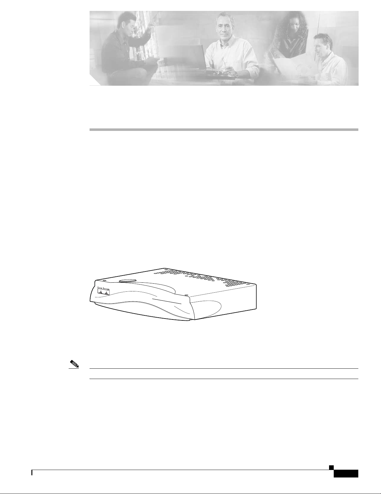
The Cisco ATA analog telephone adaptors are handset-to-Ethernet adaptors that allow regular analog
telephones to operate on IP-based telephony networks. Cisco ATAs support two voice ports, each with
an independent telephone number. The Cisco ATA 188 also has an RJ-45 10/100
This section covers the following topics:
• H.323 Overview, page 1-2
• Hardware Overview, page 1-5
• Software Features, page 1-7
• Installation and Configuration Overview, page 1-9
Figure 1-1 Cisco ATA Analog Telephone Adaptor
BASE-T data port.
OL-4008-01
CISCO ATA 186
ANALOG TELEPHONE ADAPTO
The Cisco ATA, which operates with Cisco voice-packet gateways, makes use of broadband pipes that
are deployed through a digital subscriber line (DSL), fixed wireless-cable modem, and other Ethernet
connections.
Note The term Cisco ATA refers to both the Cisco ATA 186 and the Cisco ATA 188, unless otherwise stated.
Cisco ATA 186 and Cisco ATA 188 Analog Telephone Adaptor Administrator’s Guide (H.323)
R
72209
1-1
Page 20
H.323 Overview
72853
Chapter 1 Cisco Analog Telephone Adaptor Overview
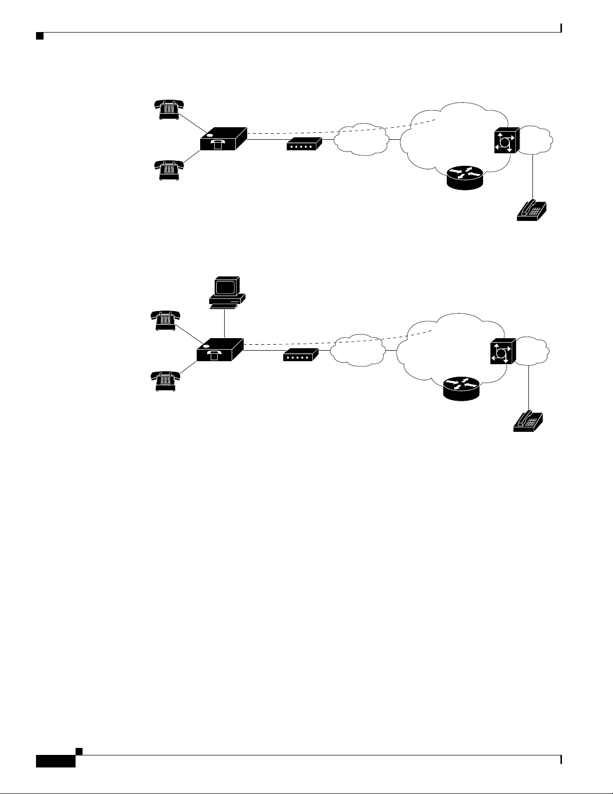
Figure 1-2 Cisco ATA 186 as Endpoint in an H.323 Network
Telephone/fax
Figure 1-3 Cisco ATA 188 as Endpoint in an H.323 Network
Telephone/fax
V
Cisco ATA 186
V
Cisco ATA 188
Ethernet
Broadband CPE
(DSL, cable,
fixed wireless)
Ethernet
Broadband CPE
(DSL, cable,
fixed wireless)
Broadband
Broadband
Layer 3
IP infrastructure
H.323 Gatekeeper
Layer 3
IP infrastructure
V
V
Voice
gateway
PSTN
Voice
gateway
PSTN
H.323 Overview
H.323 is the International Telecommunication Union (ITU) standard for transmitting voice, video, and
data across an IP network. Like other VoIP protocols, the H.323 standard is designed to address the
functions of signaling and session management from within a packet telephony network. Signaling
allows call information to be carried across network boundaries. Session management provides the
ability to control the attributes of an end-to-end call. The H.323 standard includes support for call
signaling and control, multimedia transport and control, and bandwidth control for both point-to-point
and point-to-multipoint conferences.
The H.323 standard includes the following protocols:
• Call signaling using the H.225 protocol
• Media control using the H.245 protocol
• G.711, G.722, G.723, G.728, and G.729 audio codecs
• H.261 and H.263 video codecs
• Data sharing using the T.120 protocol
• Real-time transport protocol (RTP) and RTP Control Protocol (RTCP) for media transport
H.323 Gatekeeper
72854
1-2
Cisco ATA 186 and Cisco ATA 188 Analog Telephone Adaptor Administrator’s Guide (H.323)
OL-4008-01
Page 21
Chapter 1 Cisco Analog Telephone Adaptor Overview
Components that the H.323 standard employs include a system of interconnected voice terminals,
gateways, gatekeepers, multipoint control units (MCUs), and proxy servers. Voice terminals provide
point-to-point and point-to-multipoint conference capability for audio, video, and data. Voice gateways
interconnect the packetized IP network to the PSTN or ISDN network. Gatekeepers provide admission
control and address translation services for H.323 voice terminals and gateways. MCUs enable two or
more gateways to engage in point-to-point or point-to-multipoint audio or video conferences.
This section contains descriptions of the following H.323 components:
• H.323 Terminals, page 1-3
• H.323 Gateways, page 1-3
• H.323 Gatekeepers, page 1-4
• H.323 MCUs, page 1-4
• H.323 Proxy Server, page 1-4
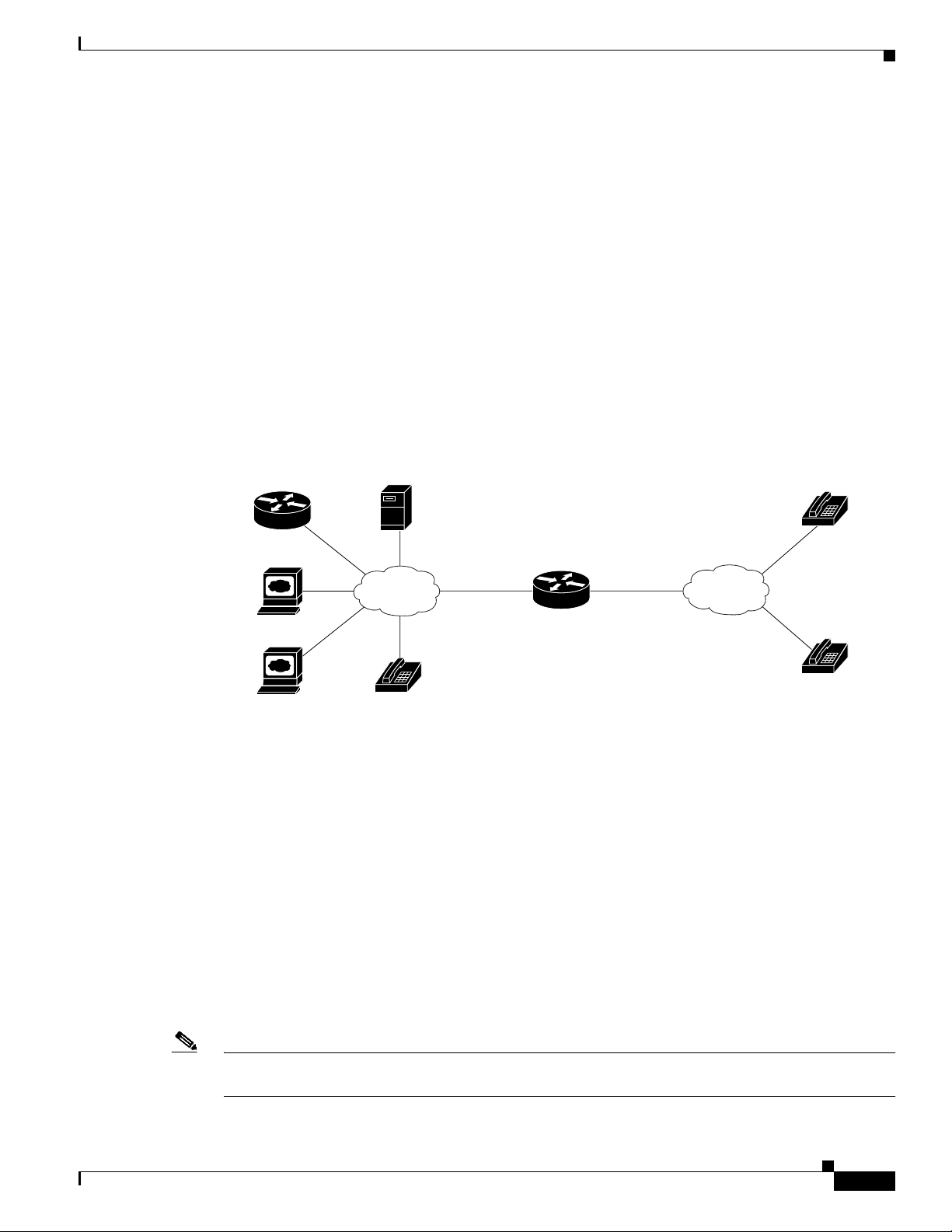
Figure 1-4 H.323 Architecture
Multipoint Control
H.323 Gatekeeper
Unit (MCU)
H.323 Overview
Analog Phone
H.323 Terminals
Voice terminals in an H.323 network must feature system control units, media transmission capabilities,
audio codecs, and network interfaces suitable for transmitting and receiving packetized data.
H.323 Gateways
H.323 gateways feature a mixture of characteristics of both standard Switched Circuit Network (SCN)
access points and H.323 access points. Gateways perform the translation of audio, video, and data
transmission formats as well as interacting with communications systems and various protocols. A
primary responsibility of an H.323 gateway is the call setup and teardown necessary to complete a call
to and from a packetized IP network and a standard switched network.
Terminal
Terminal
H.323
Network
Cisco ATA
H.323 Gateway
CSN/PSTN
72858
Analog Phone
OL-4008-01
Note Gateways are necessary in an H.323 system to connect calls over a packetized IP network to a switched
circuit network such as the PSTN.
Cisco ATA 186 and Cisco ATA 188 Analog Telephone Adaptor Administrator’s Guide (H.323)
1-3
Page 22

H.323 Overview
H.323 Gatekeepers
Gatekeepers are primarily responsible for pre-call and call-level control services for H.323 gateways.
Gatekeepers are an optional component in an H.323 system. However, if present, gatekeepers must
perform the following call setup and management services:
• Address translation for IP addresses originating from H.323 aliases (for example,
address_pool@cisco.com, for example) or E.164 addresses (for example, standard telephone
numbers)
• Admissions control for authorizing or rejecting access to H.323
• Bandwidth control for gateway bandwidth requirements
• Zone management for registered voice terminals, gateways and MCUs
When used in an H.323 system, gatekeepers can also (but are not required to) provide the following
functionality:
• Call control signaling using the gatekeeper Routed Call Signaling model
• Call authorization to restrict access to certain voice terminals or gateways, or to restrict access based
on time-of-day criteria
Chapter 1 Cisco Analog Telephone Adaptor Overview
• Bandwidth management for the H.323 system that will enable the gateway to restrict access when
requested bandwidth is unavailable
• Call management including maintaining a list of active calls to indicate available and unavailable
voice terminals and gateways
H.323 MCUs
MCUs are endpoints in an H.323 network that support point-to-multipoint conferences and consist of a
multipoint controller and at least one multipoint processor responsible for receiving voice, video, and
data streams. These streams are distributed to access points participating in a point-to-multipoint
conference.
H.323 Proxy Server
An H.323 proxy server is a proxy specifically designed for the H.323 protocol and examines packets
between two communicating applications. Proxies can determine the destination of a call and perform
call-connection steps, if necessary.
H.323 proxies perform the following key functions:
• Allow voice terminals that do not support Resource Reservation Protocol (RSVP) to connect to the
proxy through remote access or local area networks with relatively reliable quality of service (QoS).
Pairs of proxies can then be employed to develop tunnels across the IP network.
• Support routing of H.323 traffic that is separate from ordinary data traffic by using
application-specific routing (ASR).
1-4
• Enable H.323 to be deployed in networks that use private address space.
• Ensure network security by configuring the proxy server to allow only H.323 traffic over the
network.
Cisco ATA 186 and Cisco ATA 188 Analog Telephone Adaptor Administrator’s Guide (H.323)
OL-4008-01
Page 23
Chapter 1 Cisco Analog Telephone Adaptor Overview
Hardware Overview
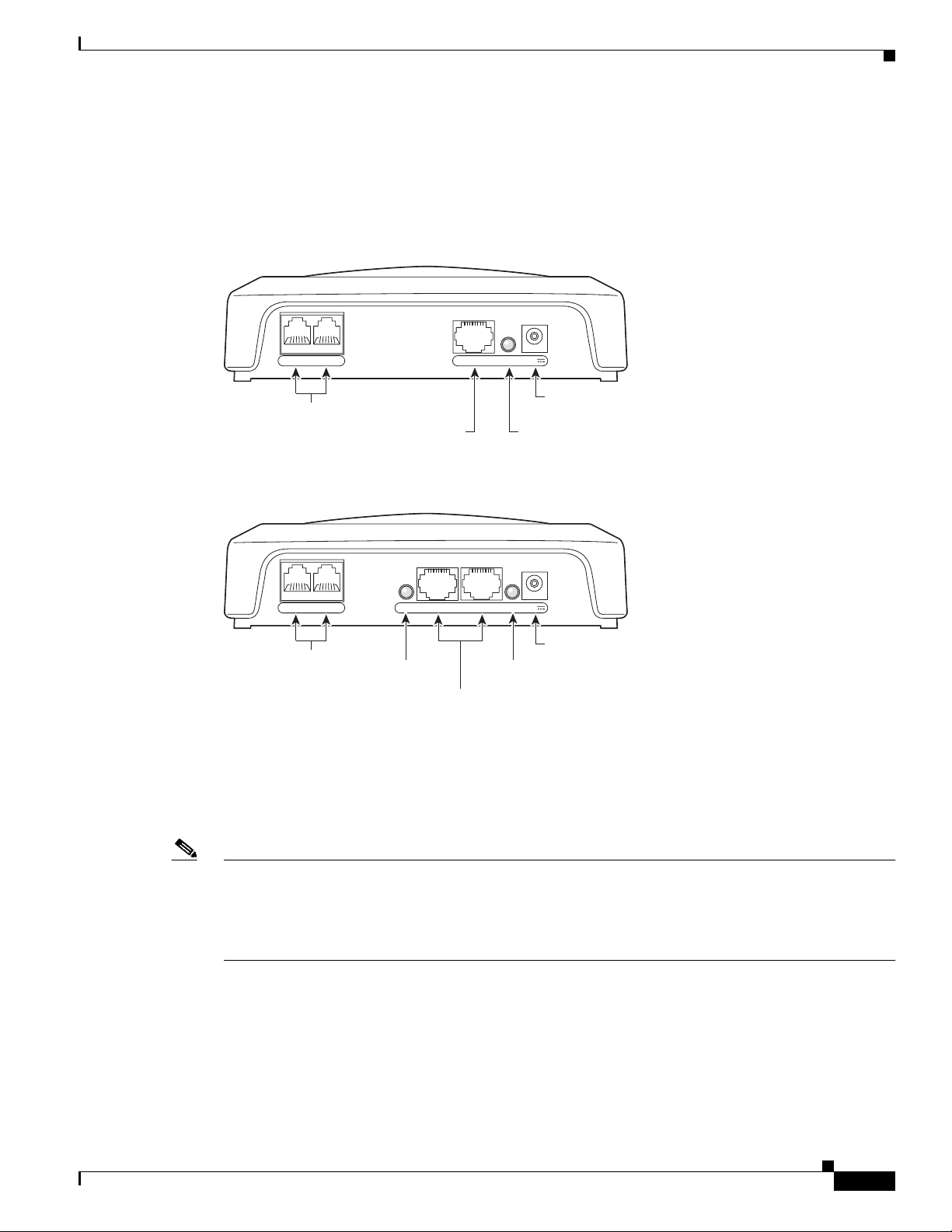
The Cisco ATA 186 and Cisco ATA 188 are compact, easy-to-install devices. Figure 1-5 shows the rear
panel of the Cisco ATA 186. Figure 1-6 shows the rear panel of the Cisco ATA 188.
Figure 1-5 Cisco ATA 186—Rear View
RJ-11 FXS ports
Figure 1-6 Cisco ATA 188—Rear View
RJ-45 10BaseT
Hardware Overview
10BaseT ACT 5VPHONE 1 PHONE 2
72210
Power
connector
ACT LED
10/100 UPLINK10/100 PC LINKLINK 5VPHONE 1 PHONE 2
72211
Power
RJ-11 FXS ports
LINK LED
RJ-45 10/100BaseT ports
LINK LED
connector
The unit provides the following connectors and indicators:
• 5V power connector.
• Two RJ-11 FXS (Foreign Exchange Station) ports—The Cisco ATA supports two independent RJ-11
telephone ports that can connect to any standard analog telephone device. Each port supports either
voice calls or fax sessions, and both ports can be used simultaneously.
Note The Cisco ATA186-I1 and Cisco ATA188-I1 provide 600-ohm resistive impedance. The Cisco
ATA186-I2 and Cisco ATA188-I2 provide 270 ohm + 750 ohm // 150-nF complex impedance. The
impedance option is requested when you place your order and should match your specific application.
If you are not sure of the applicable configuration, check your country or regionaltelephone impedance
requirements.
OL-4008-01
Cisco ATA 186 and Cisco ATA 188 Analog Telephone Adaptor Administrator’s Guide (H.323)
1-5
Page 24
Hardware Overview
Note The Cisco ATA 188 performs auto-negotiation for duplexity and speed and is capable of 10/100 Mbps,
Chapter 1 Cisco Analog Telephone Adaptor Overview
• Ethernet ports
–
The Cisco ATA 186 has one RJ-45 10BASE-T uplink Ethernet port to connect the
Cisco ATA 186 to a 10/100BASE-T hub or another Ethernet device.
–
The Cisco ATA 188 has two Ethernet ports: an RJ-45 10/100BASE-T uplink port to connect the
Cisco ATA 188 to a 10/100BASE-T hub or another Ethernet device and an RJ-45
10/100BASE-T data port to connect an Ethernet-capable device, such as a computer, to the
network.
full-duplex operation. The Cisco ATA 186 is fixed at 10 Mbps, half-duplex operation.
• The Cisco ATA 188 RJ-45 LED shows network link and activity. The LED blinks twice when the
Cisco ATA is first powered on, then turns off if there is no link or activity. The LED blinks to show
network activity and is solid when there is a link.
• The Cisco ATA 186 RJ-45 LED is solid when the Cisco ATA is powered on and blinks to show
network activity.
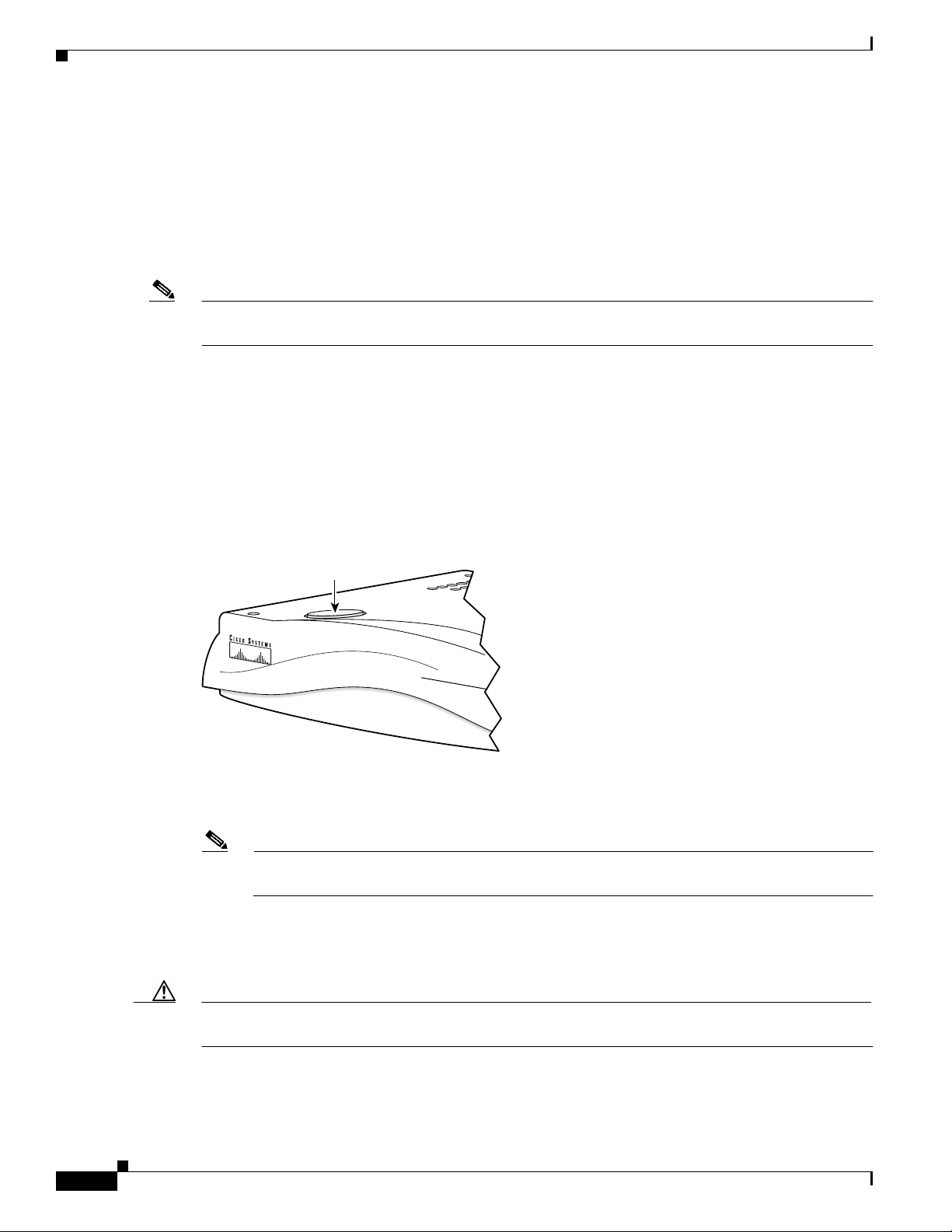
• Function button—The function button is located on the top panel of the unit (see Figure 1-7).
Figure 1-7 Function Button
Function
button
CISCO ATA 186
ANALOG TELEPHONE ADAPTOR
72214
The function button lights when you pick up the handset of a telephone attached to the Cisco ATA.
The button blinks quickly when the Cisco ATA is upgrading its configuration.
Note If the function button blinks slowly, the Cisco ATA cannot find the DHCP server. Check your
Ethernet connections and make sure the DHCP server is available.
Pressing the function button allows you to access to the voice configuration menu. For additional
information about the voice configuration menu, see the “Voice Configuration Menu” section on
page 3-15.
1-6
Caution Never press the function button during an upgrade process. Doing so may interfere with the process and
may permanently disable the Cisco ATA.
Cisco ATA 186 and Cisco ATA 188 Analog Telephone Adaptor Administrator’s Guide (H.323)
OL-4008-01
Page 25

Chapter 1 Cisco Analog Telephone Adaptor Overview
Software Features
The Cisco ATA supports the following protocols, services and methods:
• Voice Codecs Supported, page 1-7
• Additional Supported Signaling Protocols, page 1-7
• Other Supported Protocols, page 1-7
• Cisco ATA H.323 Services, page 1-8
• Fax Services, page 1-9
• Supplementary Services, page 1-9
Voice Codecs Supported
The Cisco ATA supports the following voice codecs (check your other network devices for the codecs
they support):
• G.711µ-law
• G.711A-law
Software Features
• G.723.1
• G.729
• G.729A
• G.729B
• G.729AB
Additional Supported Signaling Protocols
In addition to H.323, the Cisco ATA supports the following signaling protocols:
• Session Initiation Protocol (SIP)
• Skinny Client Control Protocol (SCCP)
• Media Gateway Control Protocol (MGCP)
H.323 and SIP share the same software image. SCCP and MGCP also share a software image, which is
separate from the H.323/SIP image. If you wish to perform a cross-protocol upgrade from H.323 to
another signaling image, see the “Upgrading the Signaling Image from a TFTP Server” section on
page 8-1.
Other Supported Protocols
OL-4008-01
Other protocols that the Cisco ATA supports include the following:
• 802.1Q VLAN tagging
• Cisco Discovery Protocol (CDP)
• Domain Name System (DNS)
• Dynamic Host Configuration Protocol (DHCP)
Cisco ATA 186 and Cisco ATA 188 Analog Telephone Adaptor Administrator’s Guide (H.323)
1-7
Page 26

Software Features
• Internet Control Message Protocol (ICMP)
• Internet Protocol (IP)
• Real-Time Transport Protocol (RTP)
• Transmission Control Protocol (TCP)
• Trivial File Transfer Protocol (TFTP)
• User Datagram Protocol (UDP)
Cisco ATA H.323 Services
For a list of required H.323 parameters as well as descriptions of all supported Cisco ATA H.323 services
and cross references to the parameters for configuring these services, see Chapter 4, “Basic and
Additional H.323 Services.”
These services include the following features:
• Supports direct IP dialing to and from a Cisco ATA without using an H.323 gatekeeper
• Supports direct IP dialing in addition to proxy-routed calls to and from either phone
Chapter 1 Cisco Analog Telephone Adaptor Overview
• Uses the same configurable MediaPort to transmit and receive RTP audio
• Uses UDP only for H.323 RAS message transmission
• Uses a TCP connection for H.225/Q.931 signaling (such as call setup, call proceeding, alerting, and
call connect)
• IP address assignment—DHCP-provided or statically configured
• Cisco ATA configuration by means of a TFTP server, web browser, or voice configuration menu.
• VLAN configuration
• Cisco Discovery Protocol (CDP)
• Low-bit-rate codec selection
• User authentication
• Configurable tones (dial tone, busy tone, alert tone, reorder tone, call waiting tone)
• Dial plans
• User-configurable, call-waiting, permanent default setting
• Silence suppression and comfort noise generation for G.711, G.723.1 (G.723.1 Annex A), and
G.,729 (G.729 Annex B)
• Caller ID format
• Ring cadence format
• Hook-flash detection timing configuration
• UDP Type of Service (ToS) configuration
1-8
• Hotline and warmline support (private line automatic ringdown)
• Debugging and diagnostic tools
Cisco ATA 186 and Cisco ATA 188 Analog Telephone Adaptor Administrator’s Guide (H.323)
OL-4008-01
Page 27

Chapter 1 Cisco Analog Telephone Adaptor Overview
Fax Services
The Cisco ATA supports two modes of fax services, in which fax signals are transmitted using the G.711
codec:
• Fax pass-through mode—Receiver-side Called Station Identification (CED) tone detection with
automatic G.711A-law or G.711µ-law switching.
• Fax mode—The Cisco ATA is configured as a G.711-only device.
How you set Cisco ATA fax parameters depends on what network gateways are being used. You may
need to modify the default fax parameter values (see Chapter 7, “Configuring and Debugging Fax
Services”).
Note Success of fax transmission depends on network conditions and fax modem response to these conditions.
The network must have reasonably low network jitter, network delay, and packet loss rate.
Supplementary Services
Installation and Configuration Overview
H.323 supplementary services are services that you can use to enhance your telephone service. For
information on how to enable and subscribe to these services, see the “CallFeatures” section on
page 5-24 and the “PaidFeatures” section on page 5-25.
For information on how to use these services, see Appendix A, “Using H.323 Supplementary Services.”
The following list contains the H.323 supplementary services that the Cisco ATA supports:
• Caller ID
• Calling line ID presentation/rejection (CLIP/CLIR)
• Call waiting
• Call waiting Caller ID
• Three-way calling
Installation and Configuration Overview
Table 1-1 provides the basic steps required to install and configure the Cisco ATA to make it operational.
Table 1-1 Overview of the Steps Required to Install and Configure the Cisco ATA and Make it Operational
Action Reference
1. Plan the network and Cisco ATA configuration.
2. Install the Ethernet connection.
3. Install and configure the other network devices.
4. Install the Cisco ATA but do not power up the Cisco ATA yet. What the Cisco ATA Package Includes, page 2-2
5. Download the desired Cisco ATA release software zip file from
the Cisco web site, then configure the Cisco ATA.
Chapter 3, “Configuring the Cisco ATA for H.323”
OL-4008-01
Cisco ATA 186 and Cisco ATA 188 Analog Telephone Adaptor Administrator’s Guide (H.323)
1-9
Page 28

Installation and Configuration Overview
Action Reference
6. Power up the Cisco ATA.
7. Periodically, you can upgrade the Cisco ATA to a new signaling
image by using the TFTP server-upgrade method or the
manual-upgrade method.
Chapter 8, “Upgrading the Cisco ATA Signaling
Image”
Chapter 1 Cisco Analog Telephone Adaptor Overview
1-10
Cisco ATA 186 and Cisco ATA 188 Analog Telephone Adaptor Administrator’s Guide (H.323)
OL-4008-01
Page 29

CHAPTER
2
Installing the Cisco ATA
This section provides instructions for installing the Cisco ATA 186 and Cisco ATA 188. Before you
perform the installation, be sure you have met the following prerequisites:
• Planned the network and Cisco ATA configuration.
• Installed the Ethernet connection.
• Installed and configured the other network devices.
This section contains the following topics:
• Safety Recommendations, page 2-1
• What the Cisco ATA Package Includes, page 2-2
• What You Need, page 2-2
• Installation Procedure, page 2-2
• Power-Down Procedure, page 2-5
Note The term Cisco ATA is used throughout this manual to refer to both the Cisco ATA 186 and the
Cisco ATA 188, unless differences between the Cisco ATA 186 and Cisco ATA 188 are explicitly stated.
Safety Recommendations
To ensure general safety, follow these guidelines:
• Do not get this product wet or pour liquids into this device.
• Do not open or disassemble this product.
• Do not perform any action that creates a potential hazard to people or makes the equipment unsafe.
• Use only the power cube that comes with the Cisco ATA.
Warning
Warning
Ultimate disposal of this product should be handled according to all national laws and regulations.
Read the installation instructions before you connect the system to its power source.
OL-4008-01
Cisco ATA 186 and Cisco ATA 188 Analog Telephone Adaptor Administrator’s Guide (H.323)
2-1
Page 30

What the Cisco ATA Package Includes
Chapter 2 Installing the Cisco ATA
Warning
Warning
The plug-socket combination must be accessible at all times because it serves as the main
disconnecting device.
Do not work on the system or connect or disconnect cables during periods of lightning activity.
For translated warnings, see the Regulatory Compliance and Safety Information for the Cisco ATA 186
and Cisco ATA 188 manual.
What the Cisco ATA Package Includes
The Cisco ATA package contains the following items:
• Cisco ATA 186 or Cisco ATA 188 Analog Telephone Adaptor
• Read Me First - ATA Boot Load Information
• Cisco ATA 186 and Cisco ATA 188 Analog Telephone Adaptor at a Glance
• Regulatory Compliance and Safety Information for the Cisco ATA 186 and Cisco ATA 188
• 5V power adaptor
• Power cord
Note The Cisco ATA is intended for use only with the 5V DC power adaptor that comes with the unit.
What You Need
You also need the following items:
• Category-3 10BASE-T or 100BASE-T or better Ethernet cable. One cable is needed for each
Ethernet connection.
A Category-3 Ethernet cable supports 10BASE-T for up to 100 meters without quality degradation,
and a Category-3 Ethernet cable supports 100BASE-T for up to 10 meters without quality
degradation.
For uplink connections, use a crossover Ethernet cable to connect the Cisco ATA to another Ethernet
device (such as a router or PC) without using a hub. Otherwise, use straight-through Ethernet cables
for both uplink and data port connections.
• Access to an IP network
• One or two analog Touch-Tone telephones or fax machines, or one of each
Installation Procedure
After the equipment is in place, see Figure 2-1 (for Cisco ATA 186) or Figure 2-2 (for Cisco ATA 188)
and follow the next procedure to install the Cisco ATA.
2-2
Cisco ATA 186 and Cisco ATA 188 Analog Telephone Adaptor Administrator’s Guide (H.323)
OL-4008-01
Page 31

Chapter 2 Installing the Cisco ATA
Figure 2-1 Cisco ATA 186 Rear Panel Connections
Analog telephones
Installation Procedure
10BaseT ACT 5VPHONE 1 PHONE 2
72212
Power outlet
IP network
(or fax)
5V power
adaptor
Power cord
Figure 2-2 Cisco ATA 188 Rear Panel Connections
10/100 UPLINK10/100 PC LINKLINK 5VPHONE 1 PHONE 2
IP network
Analog telephones
(or fax)
PC
5V power
adaptor
72213
Power outlet
OL-4008-01
Power cord
Procedure
Step 1 Place the Cisco ATA near an electrical power outlet.
Step 2 Connect one end of a telephone line cord to the Phone 1 input on the rear panel of the Cisco ATA.
Connect the other end to an analog telephone set.
Cisco ATA 186 and Cisco ATA 188 Analog Telephone Adaptor Administrator’s Guide (H.323)
2-3
Page 32

Installation Procedure
Chapter 2 Installing the Cisco ATA
If you are connecting a telephone set that was previously connected to an active telephone line, unplug
the telephone line cord from the wall jack and plug it into the Phone 1 input.
Warning
Caution Do not connect the Phone input ports to a telephone wall jack. To avoid damaging the Cisco ATA or
To reduce the risk of fire, use only No. 26 AWG or larger telecommunication line cord.
telephone wiring in the building, do not connect the Cisco ATA to the telecommunications network.
Connect the Phone port to a telephone only, never to a telephone wall jack.
Note The telephone must be switched to tone setting (not pulse) for the Cisco ATA to operate properly.
Step 3 (Optional) Connect the telephone line cord of a second telephone to the Phone 2 input port.
If you are connecting only one telephone to the Cisco ATA, you must use the Phone 1 input port.
Step 4 Connect an Ethernet cable to the uplink RJ-45 connector on the Cisco ATA. For the Cisco ATA 186,
this is the 10BASE-T connector; for the Cisco ATA 188, this is the 10/100UPLINK connector.
Use a crossover Ethernet cable to connect the Cisco ATA to another Ethernet device (such as a router or
PC) without using a hub. Otherwise, use a straight-through Ethernet cable.
Step 5 (Cisco ATA 188 only—optional) Connect a straight-through Ethernet cable from your PC to the 10/100
PC RJ-45 connector on the Cisco ATA.
Step 6 Connect the socket end of the power cord to the 5V DC power adaptor.
Step 7 Insert the power adaptor cable into the power connector on the Cisco ATA.
Warning
This product relies on the building’s installation for short-circuit (overcurrent) protection. Ensure that
a fuse or circuit breaker no larger than 120 VAC, 15A U.S. (240VAC, 10A international) is used on the
phase conductors (all current-carrying conductors).
Step 8 Connect the plug end of the 5V DC power adaptor cord into an electrical power outlet.
When the Cisco ATA is properly connected and powered up, the green activity LED flashes to indicate
network activity. This LED is labeled ACT on the rear panel of the Cisco ATA 186 and is labeled LINK
on the rear panel of the Cisco ATA 188.
Caution Do not cover or block the air vents on either the top or the bottom surface of the Cisco ATA. Overheating
can cause permanent damage to the unit.
For more information about LEDs and the function button, see the “Hardware Overview” section on
page 1-5.
2-4
Cisco ATA 186 and Cisco ATA 188 Analog Telephone Adaptor Administrator’s Guide (H.323)
OL-4008-01
Page 33

Chapter 2 Installing the Cisco ATA
Power-Down Procedure
Caution If you need to power down Cisco ATA 186 or Cisco 188 at any time, use the following power-down
procedure to prevent damage to the unit.
Procedure
Step 1 Unplug the RJ45 Ethernet cable
Step 2 Wait for 20 seconds.
Step 3 Unplug the power cable.
Power-Down Procedure
OL-4008-01
Cisco ATA 186 and Cisco ATA 188 Analog Telephone Adaptor Administrator’s Guide (H.323)
2-5
Page 34

Power-Down Procedure
Chapter 2 Installing the Cisco ATA
2-6
Cisco ATA 186 and Cisco ATA 188 Analog Telephone Adaptor Administrator’s Guide (H.323)
OL-4008-01
Page 35

CHAPTER
3
Configuring the Cisco ATA for H.323
This section describes how to configure the Cisco ATA to operate with the H.323 signaling image and
how the Cisco ATA obtains the latest signaling image.
You can configure the Cisco ATA for use with H.323 with any of the following methods:
• By using a TFTP server—This is the Cisco-recommended method for deploying a large number of
Cisco ATAs. This method allows you to set up a unique Cisco ATA configuration file or a
configuration file that is common to all Cisco ATAs. The Cisco ATA can automatically download its
latest configuration file from the TFTP server when the Cisco ATA powers up, is refreshed or reset,
or when the specified TFTP query interval expires.
• By using manual configuration:
–
Voice configuration menu—This is the method you must use if the process of establishing IP
connectivity for the Cisco ATA requires changing the default network configuration settings. These
settings are CDP, VLAN, and DHCP. You also can use the voice configuration menu to review all IP
connectivity settings. The voice configuration menu can also be used when Web access is not
available.
–
Web-based configuration—This method is convenient if you plan to deploy a small number of
Cisco ATAs in your network. To use this method, the Cisco ATA must first obtain IP connectivity,
either through the use of a DHCP server or by using the voice configuration menu to statically
configure IP addresses.
OL-4008-01
This section contains the following topics:
• Default Boot Load Behavior, page 3-2—This section describes the process that the Cisco ATA
follows by default when it boots up. It is very important to understand this process because, if your
network environment is not set up to follow this default behavior, you need to make the applicable
configuration changes. For example, by default, the Cisco ATA attempts to contact a DHCP server
for the necessary IP addresses to achieve network connectivity. However, if your network does not
use a DHCP server, you must manually configure various IP settings as described in this section.
• Specifying a Preconfigured VLAN ID or Disabling VLAN IP Encapsulation, page 3-3—This section
includes a table of the parameters you can configure for VLAN and CDP settings.
• Steps Needed to Configure the Cisco ATA, page 3-5—This section provides tables that summarize
the general configuration steps you must follow to configure the Cisco ATA.
• Configuring the Cisco ATA Using a TFTP Server, page 3-7—This section describes procedures for
configuring the Cisco ATA by using a TFTP server, which is the recommended configuration
method for the deployment of a large number of Cisco ATAs.
• Voice Configuration Menu, page 3-15—This section includes information on how to obtain basic
network connectivity for the Cisco ATA and how to perform a factory reset if necessary.
Cisco ATA 186 and Cisco ATA 188 Analog Telephone Adaptor Administrator’s Guide (H.323)
3-1
Page 36

Default Boot Load Behavior
• Cisco ATA Web Configuration Page, page 3-18—This section shows the Cisco ATA Web
configuration page and contains a procedure for how to configure Cisco ATA parameters using this
interface.
• Web Interface Access-Control Configuration, page 3-20
• Refreshing or Resetting the Cisco ATA, page 3-20—This section gives the procedure (via the Web
configuration page) for refreshing or resetting the Cisco ATA so that your most recent configuration
changes take effect immediately.
• Upgrading the H.323 Signaling Image, page 3-21—This section provides references to the various
means of upgrading your Cisco ATA signaling image.
Note The term Cisco ATA is used throughout this manual to refer to both the Cisco ATA 186 and the
Cisco ATA 188, unless differences between the Cisco ATA 186 and Cisco ATA 188 are explicitly stated.
Default Boot Load Behavior
Before configuring the Cisco ATA, you need to know how the default Cisco ATA boot load process
works. Once you understand this process, you will be able to configure the Cisco ATA by following the
instructions provided in this section and in the sections that follow.
Chapter 3 Configuring the Cisco ATA for H.323
All Cisco ATAs are shipped with a boot load signaling-protocol image. However, because this image is
not a fully functional signaling image, the image must be upgraded. The image is designed to be
automatically upgraded by a properly configured TFTP server. To configure the Cisco ATA to
automatically upgrade to the latest signaling image, see the “Upgrading the Signaling Image from a
TFTP Server” section on page 8-1.
In addition, the Cisco ATA obtains its configuration file during the boot load process.
The following list summarizes the default Cisco ATA behavior during its boot-up process:
1. The Cisco ATA uses the Cisco Discovery Protocol (CDP) to discover which VLAN to enter. If the
Cisco ATA receives a VLAN ID response from the network switch, the Cisco ATA enters that VLAN
and adds 802.1Q VLAN tags to its IP packets. If the Cisco ATA does not receive a response with a
VLAN ID from the network switch, then the Cisco ATA assumes it is not operating in a VLAN
environment and does not perform VLAN tagging on its packets.
Note If your network environment is not set up to handle this default behavior, make the necessary
configuration changes by referring to the “Specifying a Preconfigured VLAN ID or Disabling
VLAN IP Encapsulation” section on page 3-3.
2. The Cisco ATA contacts the DHCP server to request its own IP address.
Note If your network environment does not contain a DHCP server, you need to statically configure
various IP addresses so that the Cisco ATA can obtain network connectivity. For a list of
parameters that you must configure to obtain network connectivity, see Table 3-5 on page 3-16.
For instructions on how to use the voice configuration menu, which you must use to perform this
configuration, see the “Voice Configuration Menu” section on page 3-15.
3-2
3. Also from the DHCP server, the Cisco ATA requests the IP address of the TFTP server.
Cisco ATA 186 and Cisco ATA 188 Analog Telephone Adaptor Administrator’s Guide (H.323)
OL-4008-01
Page 37

Chapter 3 Configuring the Cisco ATA for H.323
4. The Cisco ATA contacts the TFTP server and downloads the Cisco ATA release software that
contains the correct signaling image for the Cisco ATA to function properly.
Note If you are not using a TFTP server, you need to manually upgrade the Cisco ATA to the correct
signaling image. For information on this procedure, see the “Upgrading the Signaling Image
Manually” section on page 8-2.
5. The Cisco ATA looks for a Cisco ATA-specific configuration file (designated by the MAC address
of the Cisco ATA and named ata<macaddress>) on the TFTP server and downloads this file if it
exists.
6. If the Cisco ATA does not find the ata<macaddress> configuration file, it looks for the
atadefault.cfg configuration file and downloads this file if it exists. This file can contain default
values for the Cisco ATA to use.
Note When the Cisco ATA is downloading its DHCP configuration, the function button on the top panel
blinks.
Specifying a Preconfigured VLAN ID or Disabling VLAN IP Encapsulation
Specifying a Preconfigured VLAN ID or Disabling VLAN IP
Encapsulation
If you want the Cisco ATA to use a preconfigured VLAN ID instead of using the Cisco Discovery
Protocol to locate a VLAN, or if you want to disable VLAN IP encapsulation, refer to Tabl e 3 - 1 for a
reference to the parameters and bits you may need to configure. Use the voice configuration menu to
configure these parameters. (See the “Voice Configuration Menu” section on page 3-15 for instructions
on using this menu.) Also, refer to Table 3-2 for a matrix on which VLAN-related parameters and bits
to configure depending on your network environment.
Table 3-1 Parameters and Bits for Preconfiguring a VLAN ID
Parameter and Bits Reference
OpFlags:
• Bit 4—Enable the use of user-specified voice VLAN ID.
• Bit 5—Disable VLAN encapsulation
• Bit 6—Disable CDP discovery.
VLANSetting:
• Bits 0-2—Specify VLAN CoS bit value (802.1P priority) for TCP
packets.
• Bits 3-5—Specify VLAN CoS bit value (802.1P priority) for UDP
packets
OpFlags, page 5-33
VLANSetting, page 5-34
OL-4008-01
• Bits 18-29—User-specified 802.1Q VLAN ID
Cisco ATA 186 and Cisco ATA 188 Analog Telephone Adaptor Administrator’s Guide (H.323)
3-3
Page 38

Specifying a Preconfigured VLAN ID or Disabling VLAN IP Encapsulation
Table 3-2 VLAN-Related Features and Corresponding Configuration Parameters
OpFlags Bit 4 OpFlags Bit 5 OpFlags Bit 6
Feature
Static VLAN101VLAN ID
CDP-acquired
000N/A
VLAN
No VLAN N/A 1 N/A N/A
No CDP N/A N/A 1 N/A
No CDP and no
011N/A
VLAN
N/A indicates that the variable is not applicable to the feature and the setting of this varaible does not affect the feature.
Chapter 3 Configuring the Cisco ATA for H.323
VLANSetting
Bits 18-29
Example
The following procedure shows you how to configure the OpFlags and VLANSetting parameters to allow
the Cisco ATA to use a user-specified VLAN ID. In this example, the voice VLAN ID is 115 (in decimal
format).
Step 1 Set bits 4-6 of the OpFlags parameter to 1, 0, and 1, respectively. This setting translates to the following
bitmap:
xxxx xxxx xxxx xxxx xxxx xxxx x101 xxxx
The remaining bits of the OpFlags parameter, using all default values, make up the following bitmap
representation:
0000 0000 0000 0000 0000 0000 0xxx 0010
Therefore, the resulting value of the OpFlags parameter becomes the following bitmap representation:
0000 0000 0000 0000 0000 0000 0101 0010
In hexadecimal format, this value is 0x00000052.
Step 2 Set bits 18-29 of the VLANSetting parameter to to voice VLAN ID 115. This setting translates to the
following bitmap
xx00 0001 1100 11xx xxxx xxxx xxxx xxxx
where 000001110011 is the binary representation of the demical value 115.
The remaining bits of the VLANSetting parameter, using all default values, make up the following
representation:
00xx xxxx xxxx xx00 0000 0000 0010 1011
Therefore, the resulting value of the VLANSetting parameter becomes the following bitmap
representation:
0000 0001 1100 1100 0000 0000 0010 1011
In hexadecimal format, this value is 0x01cc002b.
3-4
Cisco ATA 186 and Cisco ATA 188 Analog Telephone Adaptor Administrator’s Guide (H.323)
OL-4008-01
Page 39

Chapter 3 Configuring the Cisco ATA for H.323
Note If you are using the voice configuration menu to set the parameters, you must convert hexadecimal values
to decimal values. For example, the OpFlags setting of 0x00000052 is equivalent to 82 in decimal
format, and the VLANSetting of 0x01cc002b is equivalent to 30146603 in decimal format.
Steps Needed to Configure the Cisco ATA
This section contains the following topics:
• Basic Configuration Steps in a TFTP Server Environment, page 3-5
• Basic Configuration Steps in a Non-TFTP Server Environment, page 3-6
Basic Configuration Steps in a TFTP Server Environment
Table 3-3 shows the basic steps for configuring the Cisco ATA and making it operational in a typical
H.323 environment, which includes a TFTP server.
Steps Needed to Configure the Cisco ATA
Table 3-3 Basic Steps to Configure the Cisco ATA in a TFTP Environment
Action Reference
1. Download the desired Cisco ATA release software zip file from
the Cisco web site and store it on the TFTP server.
2. Follow these basic steps to create a unique Cisco ATA
configuration file, which actually entails creating two files:
a. Create a Cisco ATA configuration text file that contains
Setting Up the TFTP Server with Cisco ATA
Software, page 3-7
Creating Unique and Common Cisco ATA
Configuration Files, page 3-8
parameters that are common to all Cisco ATAs in your
network.
b. Create a unique Cisco ATA configuration text file that
contains parameters that are specific to a Cisco ATA.
Make sure to use an include command in the unique
configuration file to pull in values from the common
configuration file.
c. Convert the unique configuration file to binary format.
d. Place the unique binary configuration file on the TFTP server.
3. Optionally, create a default configuration file called
atadefault.cfg Configuration File, page 3-12
atadefault.cfg, which the Cisco ATA will download from the
TFTP server only if the unique Cisco ATA file called
ata<macaddress> does not exist on the TFTP server.
4. Configure the upgradecode parameter so that the Cisco ATA will
obtain the correct signaling image from the TFTP server when the
Upgrading the Signaling Image from a TFTP Server,
page 8-1
Cisco ATA powers up.
5. Configure the desired interval for the Cisco ATA to contact the
Setting Up User IDs for the Cisco ATA, page 4-3
TFTP server to check for a configuration-file update or an
upgrade of the signaling image file.
OL-4008-01
Cisco ATA 186 and Cisco ATA 188 Analog Telephone Adaptor Administrator’s Guide (H.323)
3-5
Page 40

Chapter 3 Configuring the Cisco ATA for H.323
Steps Needed to Configure the Cisco ATA
Table 3-3 Basic Steps to Configure the Cisco ATA in a TFTP Environment (continued)
Action Reference
6. Configure the method with which the Cisco ATA will locate the
TFTP server at boot up time.
7. Power up the Cisco ATA.
8. If you make configuration changes to the Cisco ATA or upgrade
Configuring the Cisco ATA to Obtain its
Configuration File from the TFTP Server, page 3-12
Refreshing or Resetting the Cisco ATA, page 3-20
the signaling image on the TFTP server, you can refresh the
Cisco ATA so that these changes take effect immediately.
Otherwise, these changes will take effect when the specified
interval (CfgInterval parameter value) for the TFTP query
expires.
Basic Configuration Steps in a Non-TFTP Server Environment
Table 3-4 shows the basic steps for configuring the Cisco ATA without using the TFTP server method.
Table 3-4 Basic Steps to Configure the Cisco ATA Without Using the TFTP Server Method
Action Reference
1. Download the desired Cisco ATA release software zip file from the Cisco web site:
a. If you are a registered CCO user. go to the following URL:
http://www.cisco.com/cgi-bin/tablebuild.pl/ata186
b. Download the zip file that contains the software for the applicable release and signaling
image you are using. The contents of each file are described next to the file name.
c. Extract the files to the desired location on your PC.
Note The file that contains the protocol signaling image has an extension of .zup.
2. Manually upgrade the Cisco ATA to the correct signaling image. Upgrading the Signaling
Image Manually, page 8-2
3. Configure the Cisco ATA by using either one of the manual-configuration methods. • Voice Configuration
Menu, page 3-15
• Cisco ATA Web
Configuration Page,
page 3-18
4. Power up the Cisco ATA.
3-6
Cisco ATA 186 and Cisco ATA 188 Analog Telephone Adaptor Administrator’s Guide (H.323)
OL-4008-01
Page 41

Chapter 3 Configuring the Cisco ATA for H.323
Configuring the Cisco ATA Using a TFTP Server
Configuring the Cisco ATA Using a TFTP Server
The TFTP method of configuration is useful when you have many Cisco ATA because you can use a
TFTP server for remote, batch configuration of Cisco ATAs. A TFTP server can host one unique
configuration file for each Cisco ATA.
This section contains the following topics:
• Setting Up the TFTP Server with Cisco ATA Software, page 3-7
• Configurable Features and Related Parameters, page 3-7
• Creating Unique and Common Cisco ATA Configuration Files, page 3-8
• atadefault.cfg Configuration File, page 3-12
• Configuring the Cisco ATA to Obtain its Configuration File from the TFTP Server, page 3-12
Setting Up the TFTP Server with Cisco ATA Software
This section provides the procedure for the Cisco ATA administrator to obtain the correct Cisco ATA
software and set up the TFTP server with this software.
Procedure
Step 1 If you are a registered CCO user. go to the following URL:
http://www.cisco.com/cgi-bin/tablebuild.pl/ata186
Step 2 Download the zip file that contains the software for the applicable release and signaling image you are
using. The contents of each file are described next to the file name. Save the zip file onto a floppy disc.
Note The file that contains the protocol signaling image has an extension of .zup.
Step 3 Extract the signaling files onto the TFTP server. This should be the same TFTP server that will contain
the binary Cisco ATA configuration file that you create (either ata<macaddress> or atadefault.cfg).
Configurable Features and Related Parameters
Table 4-1 on page 4-2 contains a list of all required H.323 parameters. These parameters must be
properly configured for the Cisco ATA to work.
For descriptions of important Cisco ATA H.323 services that you can configure, and references to their
configuration parameters, see the “Important Basic H.323 Services” section on page 4-1 and the
“Additional H.323 Services” section on page 4-7.
OL-4008-01
Table 4-4 on page 4-12 lists, in alphabetical order, various features that you can configure for the
Cisco ATA. Table 4-4 on page 4-12 also includes links to the related parameter that allows you to
configure each of these features. Each link takes you to a detailed description of the parameter that
includes its default values.
For an example of how to configure parameters for the TFTP Server configuration method, see the
“Creating Unique and Common Cisco ATA Configuration Files” section on page 3-8.
Cisco ATA 186 and Cisco ATA 188 Analog Telephone Adaptor Administrator’s Guide (H.323)
3-7
Page 42

Chapter 3 Configuring the Cisco ATA for H.323
Configuring the Cisco ATA Using a TFTP Server
Note Be sure to configure the UseSIP parameter to the value of 0 (its default) to enable the H.323 protocol.
Creating Unique and Common Cisco ATA Configuration Files
If you have many Cisco ATAs to configure, a good approach is to create two configuration files:
• One file that will contain only parameter values unique to a specific Cisco ATA.
• One file for parameters that will be configured with values common to a group of Cisco ATAs. If
this file is updated, all Cisco ATA devices in this common group can obtain the new configuration
data in a batch-mode environment.
The following procedure demonstrates the steps needed to create these configuration files.
Note The parameters used in this section help illustrate the process of creating a unique Cisco ATA
configuration file, and do not include all required H.323 parameters in the examples. See Chapter 5,
“Parameters and Defaults,” for complete listings and descriptions of required parameters and additional
configurable features. Also, refer back to Table 3-3 on page 3-5 for all main configuration steps.
Procedure
Step 1 Use the example_uprofile.txt file as a template for creating a text file of values that are common to one
group of Cisco ATAs. The example_uprofile.txt file is included in the software-release zip file and
contains all default values. This file is shown without its annotations in the “Configuration Text File
Template” section on page 5-2.
Copy the example_uprofile.txt file and save it with a meaningful name, such as common.txt.
Step 2 Configure all common parameters by editing the text file as desired. For example, you might configure
some parameters as follows:
ToConfig:0
UseTftp:1
DHCP:1
TFtpURL:10.10.10.1
UseSIP:0
Tip It is helpful to always include the parameter/value of ToConfig:0 in the Cisco ATA configuration
file so that every time this file is downloaded to the Cisco ATA, it will set ToConfig to 0, which
the appropriate value for this parameter once the Cisco ATA has been configured. If ToConfig is
1, the Cisco ATA will continue to unnecessarily contact the TFTP server.
The settings in this example indicate that a group of Cisco ATAs is using the TFTP server with an IP
address of 10.10.10.1 to obtain their configuration files. These Cisco ATAs will use a DHCP server to
obtain their own IP addresses but not to obtain the TFTP server IP address (because the TftpURL
parameter has a configured value).
3-8
Step 3 Save your changes.
Cisco ATA 186 and Cisco ATA 188 Analog Telephone Adaptor Administrator’s Guide (H.323)
OL-4008-01
Page 43

Chapter 3 Configuring the Cisco ATA for H.323
Step 4 Use the example_uprofile.txt file again, this time as a template for creating a text file of values that are
specific to one Cisco ATA. For example, you might configure the following parameters:
UserID:8530709
GkorProxy:192.168.1.1
Save this file of Cisco ATA-specific parameters as:
ata<macaddress>.txt
where macaddress is the non-dotted hexadecimal version of the MAC address of the Cisco ATA you are
configuring. This non-dotted hexadecimal MAC address is labeled on the bottom of most Cisco ATAs
next to the word “MAC.” The file name must be exactly 15 characters long. (However, if this filename
is supplied by the DHCP server, the name can be as long as 31 characters and can be any name with
printable ASCII characters.)
If necessary, you can obtain the non-dotted hexadecimal MAC address by using the atapname.exe
command. For information on using the atapname.exe command, see the “Using atapname.exe Tool to
Obtain MAC Address” section on page 3-10. That section includes an example of a dotted decimal MAC
address and its corresponding non-dotted hexadecimal address.
Note The ata<macaddress>.txt file should contain only those parameters whose values are different
from the file of common parameters. Parameter values in the ata<macaddress> configuration file
will overwrite any manually configured values (values configured through the web or voice
configuration menu) when the Cisco ATA powers up or refreshes.
Configuring the Cisco ATA Using a TFTP Server
Step 5 On the top line of the ata<macaddress>.txt file, add an include command to include the name of the
common-parameters file, and save the file.
include:common.txt
UserID:8530709
GkorProxy:192.168.1.1
Step 6 Run the cfgfmt.exe tool, which is bundled with the Cisco ATA software, on the ata<macaddress>.txt text
file to generate the binary configuration file. If you wish to encrypt the binary file for security reasons,
see the “Using the EncryptKey Parameter and cfgfmt Tool” section on page 3-11.
The syntax of the cfgfmt program follows:
Syntax
cfgfmt [-eRC4Password] -tpTagFile input-text-file output-binary-file
–
-eRC4Password is the optional RC 4key to encrypt the binary TFTP file provided by the
cfgfmt program (up to eight alphanumeric characters).
–
pTagFile is the command used to specify the ptag.dat file that is provided with the
Cisco ATA software version you are running. Search on the keyword ptag to find the complete
name of the ptag file that is included with the Cisco ATA software for the signaling protocol
you are using. Be sure this file resides in the same directory from which you are running the
cfgfmt program. The ptag.dat file is used by cfgfmt.exe to format a text input representation of
the parameter/value pairs to its output binary representation.input-text-file is the input
text file representation of the Cisco ATA configuration file.
–
input-text-file is the input text file representation of the Cisco ATA configuration file.
–
output-binary-file is the final output binary file that Cisco ATA uses as the TFTP
configuration file.
OL-4008-01
Cisco ATA 186 and Cisco ATA 188 Analog Telephone Adaptor Administrator’s Guide (H.323)
3-9
Page 44

Configuring the Cisco ATA Using a TFTP Server
Example
cfgfmt -tptag.dat ata0a141e28323c.txt ata0a141e28323c
This example is based on a Cisco ATA MAC address of 10.20.30.40.50.60, which converts to the
two-digit, lower-case hexadecimal representation of each integer as 0a141e28323c.
When you convert the ata<macaddress>.txt file to a binary file, the binary file will merge the two text
files to form one Cisco ATA-specific binary configuration file for your Cisco ATA.
If the same parameter is configured with different values in these two files, the value in the
ata<macaddress>.txt file takes precedence over the value in the common.txt file.
Step 7 Store the binary configuration file in the TFTP server root directory.
When the Cisco ATA powers up, it will retrieve its unique configuration file from the TFTP server.
Step 8 If you want to make configuration changes after boot up, repeat the process of creating or editing the
text files containing the desired parameters, then converting the ata<macaddress>.txt text file to the
binary file and storing the binary file on the TFTP server. For the configuration changes to take effect
immediately, refresh the Cisco ATA. (See the “Refreshing or Resetting the Cisco ATA” section on
page 3-20.)
After being refreshed, the Cisco ATA will download the updated ata<macaddress> configuration file.
Chapter 3 Configuring the Cisco ATA for H.323
Note If you do not perform a refresh procedure, the Cisco ATA will update its configuration the next
time it contacts the TFTP server, which is based on the configured value of the CfgInterval
parameter.
Using atapname.exe Tool to Obtain MAC Address
This bundled tool is useful for converting the dotted decimal version of the Cisco ATA MAC address
(available on the Cisco ATA Web configuration page or from the voice configuration menu code 24#) to
its default Cisco ATA profile name. This name has the following format:
ataxxxxxxxxxxxx
where each xx is the two-digit, lower-case hexadecimal representation of each integer in the dotted,
decimal version of the Cisco ATA MAC address. This is the name you use for the unique Cisco ATA
binary configuration file.
The following command and output show an example of this command.
Command Example
atapname.exe 10.20.30.40.50.60
Command Output
3-10
ata0a141e28323c
Note The same functionality is available from the voice configuration menu (voice menu code 84#), which
will announce the Cisco ATA profile name.
Cisco ATA 186 and Cisco ATA 188 Analog Telephone Adaptor Administrator’s Guide (H.323)
OL-4008-01
Page 45

Chapter 3 Configuring the Cisco ATA for H.323
Using the EncryptKey Parameter and cfgfmt Tool
The EncryptKey parameter encrypts binary files being transferred over TFTP. You can change this key
for each Cisco ATA, so that only one specific Cisco ATA can decode the information.
By default, the Cisco ATA-specific ata<macaddress> configuration file is not encrypted. If encryption
is required, however, you must manually configure the EncryptKey parameter before you boot up the
Cisco ATA so that the TFTP method is secure. Use either the voice configuration menu (see the “Voice
Configuration Menu” section on page 3-15) or the Cisco ATA web configuration page (see the
“Cisco ATA Web Configuration Page” section on page 3-18) to configure the EncryptKey parameter.
Note Because the factory-fresh ATA cannot accept encrypted configuration files, the first unencrypted file, if
intercepted, can easily be read. (You would still have to know the data structure format in order to decode
the binary information from the unencrypted file.) Therefore, the new encryption key in the unencrypted
file can be compromised.
Set the EncryptKey parameter to a nonzero value. When this value is nonzero, the Cisco ATA assumes
that the binary configuration file on the TFTP server is to be encrypted with this key by means of the
RC4 cipher algorithm. The Cisco ATA will use this key to decrypt the configuration file.
The Cisco ATA EncryptKey parameter and the encryption key used in the cfgfmt tool command syntax
must match.
Configuring the Cisco ATA Using a TFTP Server
Note For security reasons, Cisco recommends that you set the UIPassword parameter (if desired) in the
configuration file and not by using one of the manual configuration methods.
The cfgfmt.exe syntax affects how the EncryptKey parameter is used, as shown in the following
examples. In these examples, input_text is the ata<macaddress>.txt file that you will convert to binary
to create the ata<macaddress> configuration file for the Cisco ATA; output_binary is that binary
ata<macaddress> file, and Secret is the encryption key.
Syntax examples
• cfgfmt -tpTagFile input-text-file output-binary-file
If input-text-file sets the Cisco ATA EncryptKey parameter to 0, then output-binary-file is not
encrypted. If the input-text-file sets EncryptKey to a non-zero value, then output-binary-file is
encrypted with that value.
• cfgfmt -eSecret -tpTagFile input-text-file output-binary-file
If the Cisco ATA EncryptKey parameter has the value of 0 or is not included in input-text-file, the
Secret is used to encrypt the output-binary-file. If input-text-file sets the Cisco ATA EncryptKey
parameter to a nonzero value and the -e option is used, then output-binary-file is encrypted with the
EncryptKey parameter set in input-text-file and Secret is ignored.
• cfgfmt -E -tpTagFile input-text-file output-binary-file
The -E (uppercase) option means that any value specified for the Cisco ATA EncryptKey parameter
in input-text-file is ignored. However, because Secret is not specified in this example,
output-binary-file is not encrypted. Nevertheless, the EncryptKey parameter and its value, if
specified in input-file-text, will be included in output-binary-file for possible encryption at a later
time.
OL-4008-01
Cisco ATA 186 and Cisco ATA 188 Analog Telephone Adaptor Administrator’s Guide (H.323)
3-11
Page 46

Configuring the Cisco ATA Using a TFTP Server
• cfgfmt -E -eSecret -tpTagFile input-text-file output-binary-file
The -E (uppercase) option means that any value specified for the Cisco ATA EncryptKey parameter
in input-text-file is ignored and the output-binary-file is encrypted with the Secret key. However, the
EncryptKey parameter and its value, if specified in input-text-file, will be included in
output-binary-file.
atadefault.cfg Configuration File
You can create a configuration file, called atadefault.cfg, that is common to all Cisco ATAs. This configuration
file is applied to a Cisco ATA only if a unique configuration file (ata<macaddress>) does not exist for the
Cisco ATA on the TFTP server during the Cisco ATA power-up procedure.
You can use the atadefault.cfg file to provide limited functionality for when you first install the
Cisco ATA. For example, if your service provider provides the ethernet connection and VoIP telephony
service, you may need to call customer service to activate the service. If the atadefault.cfg file is
configured to provide a direct connection to the customer service center, you can simply pick up the
telephone and wait to be connected without using your regular phone.
The following procedure illustrates how to create the Cisco ATA default configuration file, convert it to
the required binary format that the Cisco ATA can read, and store it on the TFTP server so that the
Cisco ATA will download it during the boot-up process:
Chapter 3 Configuring the Cisco ATA for H.323
Procedure
Step 1 Make a copy of the example_uprofile.txt file and rename it atadefault.txt.
Step 2 Make the desired configuration changes by editing the atadefault.txt file, then save the file.
Step 3 Convert the atadefault.txt file to a binary file by running the cfgfmt.exe tool, which is bundled with the
Cisco ATA software.
Note Be sure to name the output file atadefault.cfg.
Step 4 Store the binary atadefault.cfg configuration file in the TFTP server root directory.
During the boot-up process, the Cisco ATA will download this file as its configuration file unless it first
finds a Cisco ATA-specific configuration file named for the MAC address of the Cisco ATA.
Configuring the Cisco ATA to Obtain its Configuration File from the TFTP Server
This section describes three methods for how the Cisco ATA contacts the TFTP server to obtain its
configuration file:
• Using a DHCP Server, page 3-13
3-12
–
The Cisco ATA contacts the DHCP server, which provides the IP address of the TFTP server
–
The Cisco ATA uses the DHCP server but the DHCP server does not know about the TFTP
server
• Without Using a DHCP Server, page 3-14
Cisco ATA 186 and Cisco ATA 188 Analog Telephone Adaptor Administrator’s Guide (H.323)
OL-4008-01
Page 47

Chapter 3 Configuring the Cisco ATA for H.323
Using a DHCP Server
When using a DHCP server, configuration settings vary depending on whether or not the DHCP server
is under the control of the Cisco ATA system administrator or the service provider. The simplest
configuration is when the DHCP server is under the control of the Cisco ATA administrator, in which
case the DHCP server provides the IP address of the TFTP server. Depending on who controls the DHCP
server, follow the applicable configuration procedure:
• Procedure if DHCP Server is Under Control of Cisco ATA Administrator, page 3-13
• Procedure if DHCP Server is not Under Control of Cisco ATA Administrator, page 3-13
This section also includes the topic:
• Other DHCP Options You Can Set, page 3-14
Note If no DHCP server is found and the Cisco ATA is programmed to find one, the function button
continues to blink.
Procedure if DHCP Server is Under Control of Cisco ATA Administrator
Configuring the Cisco ATA Using a TFTP Server
Procedure
Step 1 On the DHCP server, set one of the following two options:
• DHCP option 150 (TFTP server IP address)
• Standard DHCP option 66 (TFTP server name)
If you use DHCP option 150, the Cisco ATA will ignore DHCP option 66. However, if you use DHCP
option 66, you must turn off DHCP option 150 or set its value to 0.
Note You can turn off the DHCP option 150 request by using the Cisco ATA OpFlags parameter (see
the “OpFlags” section on page 5-33).
Step 2 Make sure to use default values for the following Cisco ATA parameters:
• TftpURL=0
• UseTftp=1
• DHCP=1
This completes the parameter settings and DHCP options you need to configure for this procedure. The
Cisco ATA will contact the DHCP server for the IP address of the TFTP server that contains the
Cisco ATA configuration file.
Procedure if DHCP Server is not Under Control of Cisco ATA Administrator
This is the procedure to use if the DHCP server is not under the control of the Cisco ATA administrator,
which means that the URL of the TFTP server must be manually configured.
Cisco ATA 186 and Cisco ATA 188 Analog Telephone Adaptor Administrator’s Guide (H.323)
OL-4008-01
3-13
Page 48

Configuring the Cisco ATA Using a TFTP Server
Procedure
Step 1 Using the voice configuration menu, set the parameter TftpURL to the IP address or URL of the TFTP
server. For more information on setting the TftpURL parameter, see the “TftpURL” section on page 5-5.
For information about using the Cisco ATA voice configuration menu, see the “Voice Configuration
Menu” section on page 3-15.
Note If you are not using a DHCP server to provide the TFTP server location, you must manually
configure the TftfURL. You can do this by using the voice configuration menu without first
obtaining network connectivity for the Cisco ATA. If you want to configure this value using the
Web configuration page, you first must obtain network connectivity by using the voice
configuration menu to statically configure IP address information (see the “Voice Configuration
Menu” section on page 3-15).
Step 2 Use the default value of 1 for the Cisco ATA parameter DHCP.
Step 3 Use the default value of 1 for the Cisco ATA parameter UseTftp.
This completes the parameter settings you need to configure for this procedure. The Cisco ATA will
contact the manually configured TFTP server that contains the Cisco ATA configuration file.
Chapter 3 Configuring the Cisco ATA for H.323
Other DHCP Options You Can Set
The following parameters can also be configured with DHCP:
• Boot file name of DHCP header—The ata<macaddress> binary Cisco ATA configuration file,
which can have a maximum of 31 characters and can be any name with printable ASCII characters
• Client PC address
• DHCP option 1—Client Subnet Mask
• DHCP option 3—Routers on the client’s subnet
• DHCP option 6—One or two Domain Name servers
• DHCP option 42—One or two Network Time Protocol servers
• DHCP option 43—Set this option to identify the protocol (for example, H.323)
• DHCP Option 60 (DHCP_VENDOR_CLASS_ID)—Use this parameter to identify the type of
Cisco ATA box (ATA1 86 or ATA1 88 ).
Without Using a DHCP Server
Use the following procedure if you are not using a DHCP server in your environment but are still using
a TFTP server to obtain the Cisco ATA configuration file:
Procedure
3-14
Step 1 Set the DHCP parameter to 0.
Step 2 Set the UseTFTP parameter to 1.
Step 3 Set the Cisco ATA parameter TftpURL to the IP address or URL of the TFTP server. For more
information on setting the TftpURL parameter, see the “TftpURL” section on page 5-5.
Cisco ATA 186 and Cisco ATA 188 Analog Telephone Adaptor Administrator’s Guide (H.323)
OL-4008-01
Page 49

Chapter 3 Configuring the Cisco ATA for H.323
Note If you are not using a DHCP server to provide the TFTP server location, you must manually enter
the TftpUrl using either the voice configuration menu or the Web configuration page.
Step 4 If you have done already done so, statically configure the following parameters using the voice
configuration menu (see the “Voice Configuration Menu” section on page 3-15). These are the
parameters you need to configure for the Cisco ATA to obtain network connectivity:
• StaticIP
• StaticRoute
• StaticNetMask
Other parameters that are normally supplied by DHCP may be provided statically by configuring their
values. These parameters are:
• DNS1IP
• DNS2IP
• NTPIP
• AltNTPIP
Voice Configuration Menu
• Domain
This completes the parameter settings you need to configure in order for the Cisco ATA to contact the
TFTP server (without using DHCP) that will contain the configuration file for the Cisco ATA.
Voice Configuration Menu
The main reasons to use the voice configuration menu are to establish IP connectivity for the Cisco ATA
if a DHCP server is not being used in your network environment, and to reset the Cisco ATA to its factory
values if necessary. You can also use the voice configuration menu if you need to configure a small
number of parameters or if the web interface and TFTP configuration are not available.
Note Do not use the voice configuration menu to attempt to change any values that you configured by means
of the TFTP configuration file method. Whenever the Cisco ATA refreshes, it downloads its
ata<macaddress> configuration file or atadefault.cfg default configuration file from the TFTP server,
and the values in either of these files will overwrite the values of any corresponding parameters
configured with the voice configuration menu.
See Chapter 5, “Parameters and Defaults,” for a complete list of parameters and their definitions. Also
see Table 4-4 on page 4-12 for an alphabetical listing of configurable features and references to their
corresponding parameters.
This section contains the following topics:
OL-4008-01
• Using the Voice Configuration Menu, page 3-16
• Entering Alphanumeric Values, page 3-17
• Resetting the Cisco ATA to Factory Default Values, page 3-18
Cisco ATA 186 and Cisco ATA 188 Analog Telephone Adaptor Administrator’s Guide (H.323)
3-15
Page 50

Voice Configuration Menu
Using the Voice Configuration Menu
To manually configure the Cisco ATA by using the voice configuration menu and the telephone keypad,
perform the following steps:
Procedure
Step 1 Connect an analog touch-tone phone to the port labeled Phone 1 on the back of the Cisco ATA.
Step 2 Lift the handset and press the function button located on the top of the Cisco ATA. You should receive
the initial voice configuration menu voice prompt.
Step 3 Using the telephone keypad, enter the voice menu code for the parameter that you want to configure or
the command that you want to execute, then press #. For a list of voice menu codes, see Appendix B,
“Voice Menu Codes.”
Table 3-5 lists the menu options that you need to configure basic IP connectivity for the Cisco ATA, after
which you can use the Cisco ATA web configuration page to configure additional parameters.
Note If you are using the voice configuration menu to statically configure the Cisco ATA IP address,
you must disable DHCP by setting its value to 0.
Chapter 3 Configuring the Cisco ATA for H.323
Table 3-5 Parameters that Provide Basic IP Connectivity for the Cisco ATA
Voice Menu
Number Features
1 StaticIP—IP address of the Cisco ATA.
2 StaticRoute—Default gateway for the Cisco ATA to use.
10 StaticNetMask—Subnet mask of the Cisco ATA.
20 DHCP—Set value to 0 to disable the use of a DHCP server; set value to 1 to enable
DHCP.
21 Review the IP address of the Cisco ATA.
22 Review the default router for the Cisco ATA to use.
23 Review subnet mask of the Cisco ATA.
Step 4 Follow the voice prompts and enter the appropriate values, then press the # key.
Note Use the * key to indicate a delimiter (dot). For example, to enter an IP address of 192.168.3.1,
you would enter 192*168*3*1 on your telephone keypad.
Note When entering values for a field that contains a hexadecimal value, you must convert the
hexadecimal value to a decimal value in order to enter it into the voice configuration menu
system. For example, to enter the hexadecimal value 0x6A, you would enter the number 106 on
the telephone keypad.
3-16
Cisco ATA 186 and Cisco ATA 188 Analog Telephone Adaptor Administrator’s Guide (H.323)
OL-4008-01
Page 51

Chapter 3 Configuring the Cisco ATA for H.323
The voice configuration menu repeats the value you entered, then prompts you to press one of the
following keys:
• 1=Change your entered value
• 2=Review your entered value
• 3=Save your entered value
• 4=Review the current saved value
Step 5 Press the # key after you have entered the desired key. If you do not press the # key, the system will
automatically timeout after 10 seconds.
Step 6 Cisco strongly recommends that you set a password. Use the voice menu code 7387277 (SETPASS) to
configure a password through the voice configuration menu, after which you are prompted for the
password whenever you attempt to change a parameter value.
Step 7 After completing the configuration through the voice configuration menu, press the # key to exit.
Step 8 Hang up the telephone. The Cisco ATA configuration refreshes. The function button fast-blinks when
the refresh completes.
Voice Configuration Menu
Entering Alphanumeric Values
Some voice configuration menu options require you to enter alphanumeric characters. Alphanumeric
entry differs from numeric entry because you must press # after each character selected.
If you need to enter an alphanumeric value, the voice prompt tells you to enter an alphanumeric value;
otherwise, enter a numeric value (0 to 9).
Table 3-6 lists the keys on a telephone keypad and their respective alphanumeric characters.
Using Tabl e 3 - 6 as a guide, enter the appropriate number key on the telephone keypad as many times as
needed to select the number, letter, or symbol required. For example, to enter 58sQ, you would enter:
5 # 8 # 7 7 7 7 7 # 7 7 7 7 7 7 7 # #
Table 3-6 Alphanumeric Characters
Key Alphanumeric Characters
1 1 ./_\ @*space return +-!,?|~^#=$”‘’%<>[] :;{}()&
2 2 a b c A B C
33 d e f D E F
4 4 g h i G H I
5 5 j k l J K L
66 m n o M N O
77 p q r s P Q R S
88 t u v T U V
9 9 w x y z W X Y Z
00
OL-4008-01
Cisco ATA 186 and Cisco ATA 188 Analog Telephone Adaptor Administrator’s Guide (H.323)
3-17
Page 52

Cisco ATA Web Configuration Page
Resetting the Cisco ATA to Factory Default Values
It is possible that you may, under some circumstances, want to reset the Cisco ATA to its factory default
values. For example, this is the only way to recover a forgotten password without contacting your Cisco
representative.
To perform a factory reset, you must use the voice configuration menu and follow these steps:
Procedure
Step 1 Press the function button on the Cisco ATA.
Step 2 Press the digits 322873738 (FACTRESET) then press # on your telephone keypad.
Step 3 Press 3 on your telephone keypad to confirm that you want to reset the Cisco ATA, then hang up the phone.
Cisco ATA Web Configuration Page
Chapter 3 Configuring the Cisco ATA for H.323
You can use the Cisco ATA web configuration page in a non-TFTP configuration environment, or in a
TFTP configuration environment as a read-only record of individual customer parameters.
You can display the most recent Cisco ATA configuration file from the TFTP server by opening your web
browser and typing the following:
http://<ipaddress>/refresh
where ipaddress is the IP address of the Cisco ATA.
Figure 3-1 shows and example of the Cisco ATA web configuration page, which displays all
configurable parameters.
Note Do not use the web configuration page to attempt to change any values that you configured by means of
the TFTP configuration file method. Whenever the Cisco ATA refreshes, it downloads its
ata<macaddress> configuration file or atadefault.cfg default configuration file from the TFTP server,
and the values in either of these files will overwrite the values of any corresponding parameters
configured with the web configuration method.
3-18
Cisco ATA 186 and Cisco ATA 188 Analog Telephone Adaptor Administrator’s Guide (H.323)
OL-4008-01
Page 53

Chapter 3 Configuring the Cisco ATA for H.323
0
4
2
1
Figure 3-1 Cisco ATA Web Configuration Page
Cisco ATA Web Configuration Page
UIPassword: ToConfig:
UseTftp: TftpURL:
CfgInterval: EncryptKey:
Dhcp: StaticIP:
StaticRoute: StaticNetMask:
UID0: PWD0:
UID1: PWD1:
GkOrProxy: Gateway:
GateWay2: UseLoginID:
LoginID0: LoginID1:
AltGk: AltGkTimeOut:
GkTimeToLive: GkId:
UseSIP: SIPRegInterval:
MaxRedirect: SIPRegOn:
NATIP: SIPPort:
MediaPort: OutBoundProxy:
NatServer: NatTimer:
LBRCodec: AudioMode:
RxCodec: TxCodec:
NumTxFrames: CallFeatures:
PaidFeatures: CallerIdMethod:
FeatureTimer: Polarity:
ConnectMode: AutMethod:
TimeZone: NTPIP:
AltNTPIP: DNS1IP:
DNS2IP: UDPTOS:
SigTimer: OpFlags:
VLANSetting: NPrintf:
TraceFlags: RingOnOffTime:
IPDialPlan: DialPlan:
DialTone: BusyTone:
ReorderTone: RingBackTone:
CallWaitTone: AlertTone:
CallCmd:
* 0
0 0
3600 *
1 0.0.0.0
0.0.0.0 0.0.0.0
9300 ****
9301 ****
192.168.2.97 0
0.0.0.0 0
0 0
0 0
300 .
1 3600
5 1
0.0.0.0 5060
16384 0
0 0x00000000
0 0x00040004
2 2
2 0xffffffff
0xffffffff 0x00019e60
0x00000000 0x00000000
0x00060400 0x00000000
17 0.0.0.0
0.0.0.0 0.0.0.0
0.0.0.0 0x000000a0
0x01418564 0x00000002
0x0000002b 192.168.2.159.9300
0x00000001 2,4,25
1 *St4-|#St4-|911|1>#t8.r9t2-|0
2,31538,30831,3100,3885,1,
2,30467,28959,1191,1513,0,
1,30831,0,5493,0,0,2400,240 1,30467,0,5970,0,0,480,480,
Af;AH;BS;NA;CS;NA;Df;EB;F
2,30467,28959,1191,1513,0,
2,30831,30467,1943,2111,0,
85712
OL-4008-01
Cisco ATA 186 and Cisco ATA 188 Analog Telephone Adaptor Administrator’s Guide (H.323)
3-19
Page 54

Web Interface Access-Control Configuration
You can access the web configuration page from any graphics-capable browser, such as
Microsoft Internet Explorer or Netscape. This provides easy initial access to the Cisco ATA
configuration within the administrator’s private network.
Follow these steps to set parameters using the web configuration page:
Procedure
Step 1 Make sure that your PC and the Cisco ATA are already networked and visible to each another.
Step 2 Open your web browser.
Step 3 Enter the URL for your configuration page. The default URL for the web server is:
http://IP Address/dev
For example, the configuration page for a Cisco ATA with the IP address 192.168.3.225 is:
http://192.168.3.225/dev
Step 4 Select the values for the items that you want to configure. See Chapter 5, “Parameters and Defaults,” for
a complete list of parameters and their definitions. Also see Table 4-4 on page 4-12 for an alphabetical
listing of configurable features and references to their corresponding parameters.
Chapter 3 Configuring the Cisco ATA for H.323
Note Cisco strongly recommends that you set a password. Use the UIPassword parameter to configure a
password, after which you are prompted for the password whenever you attempt to change a parameter
value. Configuration parameters cannot be accessed through the voice configuration menu if the
password contains one or more letters and can be changed only by using the web interface or the TFTP
configuration method.
Step 5 Click apply to save your changes.
The Cisco ATA automatically refreshes its configuration.
Step 6 Close your web browser.
Web Interface Access-Control Configuration
To prevent tampering and unauthorized access to the Cisco ATA configuration, the Cisco ATA built-in
web server can be disabled by using the OpFlags parameter.
Related Parameter
OpFlags, page 5-33—Bit 7
Refreshing or Resetting the Cisco ATA
Whenever you make configuration changes to your Cisco ATA configuration file, you can refresh or reset
the Cisco ATA for these configuration changes to immediately take effect. If you do not refresh or reset
the Cisco ATA, the configuration changes will take effect the next time the Cisco ATA contacts the TFTP
server, which occurs based on the configured value of the CfgInterval parameter (see the “Configuring
the Cisco ATA Refresh Interval” section on page 4-9).
Cisco ATA 186 and Cisco ATA 188 Analog Telephone Adaptor Administrator’s Guide (H.323)
3-20
OL-4008-01
Page 55

Chapter 3 Configuring the Cisco ATA for H.323
Note A refresh procedure will update the Cisco ATA configuration file. A reset procedure will also update the
Cisco ATA configuration file, and will additionally power-down and power-up the Cisco ATA. A reset
should not be necessary if your only goal is to update the configuration file.
HTTP Procedure to Refresh the Cisco ATA
To refresh the Cisco ATA, enter the following command from your web browser:
http://<ipaddress>/refresh
where ipaddress is the IP address of the Cisco ATA that you are refreshing.
HTTP Procedure to Reset the Cisco ATA
To reset the Cisco ATA, enter the following command from your web browser:
http://<ipaddress>/reset
Upgrading the H.323 Signaling Image
where ipaddress is the IP address of the Cisco ATA that you are resetting.
HTTP Refresh and Reset Access-Control Configuration
You can configure the Cisco ATA to disable the use of the http://ip/refresh command that forces a
configuration-file update. Use Bit 8 of the OpFlags parameter to control this refresh access.
You can also configure the Cisco ATA to disable the use of the http://ip/reset command that resets the
Cisco ATA. Use Bit 9 of the OpFlags parameter to control this reset access.
Related Configuration Parameter
OpFlags, page 5-33
Upgrading the H.323 Signaling Image
For instructions on how to upgrade the Cisco ATA to the most recent H.323 signaling image, refer to the
following list:
• To use the recommended TFTP method of upgrading the Cisco ATA, see the “Upgrading the
Signaling Image from a TFTP Server” section on page 8-1.
• In the rare instance that you are not using the TFTP server to configure the Cisco ATA and to obtain
software upgrades, you must manually upgrade to the latest signaling image immediately after the
Cisco ATA boots up. In this case, see the “Upgrading the Signaling Image Manually” section on
page 8-2.
OL-4008-01
Cisco ATA 186 and Cisco ATA 188 Analog Telephone Adaptor Administrator’s Guide (H.323)
3-21
Page 56

Upgrading the H.323 Signaling Image
Chapter 3 Configuring the Cisco ATA for H.323
3-22
Cisco ATA 186 and Cisco ATA 188 Analog Telephone Adaptor Administrator’s Guide (H.323)
OL-4008-01
Page 57

CHAPTER
4
Basic and Additional H.323 Services
This section provides information about key basic and additional H.323 services that the Cisco ATA
supports:
• Important Basic H.323 Services, page 4-1—This section includes a list of parameters that you must
configure in order for the Cisco ATA to function in an H.323 environment.
• Additional H.323 Services, page 4-7—This section contains information about additional,
commonly used H.323 features, with references to the parameters for configuring these services.
• Complete Reference Table of all Cisco ATA H.323 Services, page 4-12—This section contains a
complete listing of Cisco ATA services supported for H.323, and includes cross references to the
parameters for configuring these services.
Note The term Cisco ATA refers to both the Cisco ATA 186 and the Cisco ATA 188, unless otherwise stated.
Important Basic H.323 Services
This section provides descriptions and cross references for configuring required H.323 parameters and
also for configuring important H.323 services:
• Required Parameters, page 4-1
• Setting the Signaling Image to H.323 Mode, page 4-2
• Setting Up User IDs for the Cisco ATA, page 4-3
• Using the Cisco ATA with an H.323 Gatekeeper, page 4-3
• Using the Cisco ATA Without an H.323 Gatekeeper, page 4-6
• Setting the Audio Codecs, page 4-7
Required Parameters
If the UseSIP parameter is set to 0 (you are using the H.323 protocol), you need to supply values for the
required H.323 parameters shown in Ta b l e 4-1. The Parameter column provides the name of the
parameter and a cross reference which provides a more-detailed description of the parameter.
Note See Chapter 5, “Parameters and Defaults,” for information about additional Cisco ATA parameters.
OL-4008-01
Cisco ATA 186 and Cisco ATA 188 Analog Telephone Adaptor Administrator’s Guide (H.323)
4-1
Page 58

Chapter 4 Basic and Additional H.323 Services
Important Basic H.323 Services
Table 4-1 Required H.323 Parameters and Defaults
Voice
Menu
Access
Parameter Value Type Description
UID0, page 5-10 Alphanumeric
User ID for the Phone 1 port. 3 0
string
UID1, page 5-11 Alphanumeric
User ID for Phone 2 port. 13 0
string
PWD0, page 5-10 Alphanumeric
Password for the Phone 1 port. 4 0
string
PWD1, page 5-12 Alphanumeric
Password for the Phone 2 port. 14 0
string
LoginID0, page 5-13 Alphanumeric
string
LoginID1, page 5-14 Alphanumeric
string
GkOrProxy, page 5-15 Alphanumeric
Login ID for the Phone 1 port. If this value is 0, the UID0
parameter is used for authentication.
Login ID for the Phone 2 port. If this value is 0, the UID1
parameter is used for authentication.
IP address of the H.323 gatekeeper. 5 0
string
UseLoginID, page 5-13 Boolean Enables the Cisco ATA to use its H.323 ID for
authenticated login.
AltGk, page 5-16 Alphanumeric
IP address of the statically defined alternate gatekeeper. 6 0
string
AltGkTimeOut, page 5-16 Integer The timeout value, in seconds, for an alternate gatekeeper.
The allowed range is 30 to 4294967295 seconds.
GkTimeToLive, page 5-17 Integer The “time to live” value that is used when the Cisco ATA
registers with the H.323 gatekeeper. The registration is
valid until the configured time expires.
GkId, page 5-17 Alphanumeric
Identifier for the primary H.323 gatekeeper. 91 .
string
UseSIP, page 5-18 Boolean H.323 or SIP mode selection. Set to 0 for H.323 mode. 38 0
ToConfig, page 5-4 Boolean Indicates if parameters have been set. Set this value to 0
after you have completed configuration of the Cisco ATA.
If this value remains at 1, the Cisco ATA will
unnecessarily continue to contact the TFTP server.
Code Default
46 0
47 0
93 0
251 0
250 0
80001 1
Setting the Signaling Image to H.323 Mode
If you are using the H.323 signaling protocol, you must set the UseSIP parameter to 0.
Cisco ATA 186 and Cisco ATA 188 Analog Telephone Adaptor Administrator’s Guide (H.323)
4-2
OL-4008-01
Page 59

Chapter 4 Basic and Additional H.323 Services
Setting Up User IDs for the Cisco ATA
Each Cisco ATA can support two FXS ports. You can assign a user ID, which is usually an E.164 phone
number, to each port. Use the Cisco ATA parameter UID0 to configure an ID for the Phone 1 port, and
use the UID1 parameter for the user ID of the Phone 2 port.
Related Configuration Parameters
• UID0, page 5-10
• UID1, page 5-11
Using the Cisco ATA with an H.323 Gatekeeper
The Cisco ATA can function with an H.323 gatekeeper to enable Cisco ATA registration, admission, and
use of directory services on an H.323 network. To use the Cisco ATA with a primary H.323 gatekeeper,
you need to configure the GkOrProxy parameter with the IP address assigned to the primary H.323
gatekeeper. Optionally, you can specify the primary gatekeeper identifier using the GkId parameter if
this identifier is required for the Cisco ATA to successfully register with the H.323 network.
Important Basic H.323 Services
This section contains the following topics:
• Choosing Cisco ATA Registration Mode with an H.323 Gatekeeper, page 4-3
• Setting Up Gatekeeper Time-To-Live Value, page 4-4
• Setting Up an Alternate H.323 Gatekeeper, page 4-4
• Establishing Authentication with Cisco H.323 Gatekeeper, page 4-5
Related Configuration Parameters
• GkOrProxy, page 5-15
• GkId, page 5-17
Choosing Cisco ATA Registration Mode with an H.323 Gatekeeper
The Cisco ATA can register with an H.323 gatekeeper in one of two modes:
• Single registration—Both Cisco ATA FXS ports register at the same time with the H.323 gatekeeper.
This reduces gatekeeper registration traffic by 50 percent when both ports are enabled.
• Dual registration—Each FXS port registers separately with the H.323 gatekeeper.
To configure single-mode registration, you need to set the UseLoginID parameter to 1, and then
configure the LoginID1 and LoginID2 parameters with identical values. The LoginID1 and LoginID2
parameters are used for the H.323 ID, whereas the UID0 and UID1 parameter values are used as E.164
phone numbers.
OL-4008-01
Cisco ATA 186 and Cisco ATA 188 Analog Telephone Adaptor Administrator’s Guide (H.323)
4-3
Page 60

Important Basic H.323 Services
If LoginID1 and LoginID2 are not used or are not set to identical values, the Cisco ATA uses
dual-registration mode.
Related Parameters
• LoginID0, page 5-13
• LoginID1, page 5-14
• UID0, page 5-10
• UID1, page 5-11
Setting Up Gatekeeper Time-To-Live Value
You can specify the valid duration of the H.323 gatekeeper registration, in seconds, by using the
GkTimeToLive parameter.
Related Configuration Parameter
GkTimeToLive, page 5-17
Chapter 4 Basic and Additional H.323 Services
Setting Up an Alternate H.323 Gatekeeper
To provide redundancy in systems that use an H.323 gatekeeper, the Cisco ATA allows you to either
statically configure an alternate H.323 gatekeeper or dynamically assign an H.323 gatekeeper.
To enable the static alternate gatekeeper feature, you need to configure the AltGk parameter with the IP
address assigned to the alternate H.323 gatekeeper. To enable the Cisco ATA to perform full gatekeeper
registration when it switches to a statically configured alternate H.323 gatekeeper, configure Bit 3 of the
ConnectMode parameter to the value of 1.
To enable the dynamic alternate gatekeeper feature, you need to configure the primary H.323 gatekeeper
so that the list of alternate gatekeepers is included in the H.225 RAS messages that the H.323 gatekeeper
sends to the Cisco ATA. The Cisco ATA can accept as many as four dynamic alternate gatekeepers
configured in the H.225 RAS messages. (The Cisco ATA supports the alternate gatekeeper list in
GCF/GRJ, ACF/ARJ, RCF/RRJ, and DRJ RAS messages.)
Dynamic alternate gatekeepers and static alternate gatekeepers can co-exist. When the Cisco ATA
receives an alternate gatekeeper list in an H.225 RAS message, the static alternate gatekeeper is merged
with the dynamic alternate gatekeepers. The static alternate gatekeeper is kept and given the lowest
priority.
You can configure the AltGkTimeout parameter to specify the number of seconds the Cisco ATA should
wait before it automatically switches back to the primary H.323 gatekeeper after being moved to an
alternate gatekeeper. By default, the switch-back procedure is disabled (the AltGkTimeout parameter
value is set to 0).
Related Configuration Parameters
• AltGk, page 5-16
4-4
• AltGkTimeOut, page 5-16
• ConnectMode, page 5-28
Cisco ATA 186 and Cisco ATA 188 Analog Telephone Adaptor Administrator’s Guide (H.323)
OL-4008-01
Page 61

Chapter 4 Basic and Additional H.323 Services
Establishing Authentication with Cisco H.323 Gatekeeper
You can configure the Cisco ATA to establish authentication with a Cisco H.323 Gatekeeper. The
Cisco ATA supports two authentication methods:
• Cisco registration level-security
• Cisco admission-level security (per-call basis)
To configure either authentication method, use the following procedure:
Procedure
Step 1 Set the UseLoginID parameter to 1. This setting indicates that the LoginID0 and LoginID1 fields will be
used for Cisco ATA H.323 registration.
Step 2 Set the UID0 and UID1 parameters to the E.164 phone numbers that are assigned to the FXS ports on
the Cisco ATA.
Step 3 Set the LoginID0 and LoginID1 parameters to the H.323 ID. The H.323 ID is used when the Cisco ATA
registers with the H.323 gatekeeper. This ID is also used as the account ID for the RADIUS server.
Step 4 Set the PWD0 and PWD1 parameters to the passwords for the Phone 1 and Phone 2 FXS ports (the
passwords in the RADIUS server), respectively.
Important Basic H.323 Services
Step 5 Set the NTPIP and AltNTPIP parameters to the IP addresses of the NTP servers in your network.
Step 6 Select the authentication method using the AutMethod parameter (0 indicates no authentication; 1
indicates the Cisco registration level security method; 2 indicates the Cisco admission level security
method).
Note The authentication methods are Cisco Proprietary H.235 implementations, which use the Cisco
access/clear token structure rather than the VocalTec crypto token structure.
Related Configuration Parameters
• UseLoginID, page 5-13
• AutMethod, page 5-14
• LoginID0, page 5-13
• LoginID1, page 5-14
• UID0, page 5-10
• UID1, page 5-11
• PWD0, page 5-10
• PWD1, page 5-12
OL-4008-01
• NTPIP, page 5-30
• AltNTPIP, page 5-30
Cisco ATA 186 and Cisco ATA 188 Analog Telephone Adaptor Administrator’s Guide (H.323)
4-5
Page 62

Chapter 4 Basic and Additional H.323 Services
Important Basic H.323 Services
Using the Cisco ATA Without an H.323 Gatekeeper
You can use the Cisco ATA without using an H.323 gatekeeper, as this section describes with the
following topics:
• Using the Cisco ATA With an H.323 Gateway but Without an H.323 Gatekeeper, page 4-6
• Using Multiple Cisco ATAs Without an H.323 Gatekeeper, page 4-6
Using the Cisco ATA With an H.323 Gateway but Without an H.323 Gatekeeper
You can use a Cisco ATA with an H.323 network that does not contain an H.323 gatekeeper. In this
scenario, all calls initiated from the Cisco ATA are directed to a specified H.323 gateway. To specify this
H.323 gateway, you configure its IP address using the Gateway parameter, and you disable the H.323
gatekeeper feature by setting the GkorProxy parameter to 0.
Note For all calls sent from the H.323 gateway to the Cisco ATA, the E.164 number assigned to each of the
Cisco ATA FXS ports must be included in the H.225 Setup message, either in the DestinationAddress
field or the Q.931 CalledPartyNumber field. The Cisco ATA will reject the call if it cannot find its E.164
number in the H.255 Setup message.
Related Configuration Parameters
• Gateway, page 5-12
• GkOrProxy, page 5-15
Using Multiple Cisco ATAs Without an H.323 Gatekeeper
You can make calls from one Cisco ATA to another Cisco ATA in an H.323 network that does not contain
an H.323 gatekeeper.
For one Cisco ATA to access a specific FXS port on another Cisco ATA, you use an IP dialing procedure.
The Cisco ATA originating the call must have the following information about the destination
Cisco ATA:
• E.164 phone number of the destination FXS port
• IP address of the destination Cisco ATA
To enable the IP dialing procedure, you need to set the IPDialPlan parameter to 1 to instruct the
Cisco ATA to look for the destination IP address in the dialed digits.
Example
Cisco ATA X is going to initiate a call to Cisco ATA Y (with the following pertinent information):
• IP address of Cisco ATA Y—192.168.2.112.
• E.164 phone number for the Phone 1 port of Cisco ATA Y—1:5556666
4-6
• E.164 phone number for the Phone 2 port of Cisco ATA Y—2:5558888
To call the Phone 1 port on Cisco ATA Y, you would dial 5556666**192*168*2*112#.
To call the Phone 2 port on Cisco ATA Y, you would dial 5558888**192*168*2*112#.
Cisco ATA 186 and Cisco ATA 188 Analog Telephone Adaptor Administrator’s Guide (H.323)
OL-4008-01
Page 63

Chapter 4 Basic and Additional H.323 Services
Related Configuration Parameters
• IPDialPlan, page 5-36
• DialPlan, page 5-37
Setting the Audio Codecs
You can configure the following codec-related settings:
• Low-bit-rate codec—When operating with a low-bit-rate codec, the Cisco ATA can support either
two G.723.1 connections or one G.729 connection. You must statically configure the selection of
G.723.1 or G.729 by using the LBRCodec parameter.
When G.723.1 is the low-bit-rate codec, each FXS port is allocated one G.723.1 connection. When
G.729 is used, only one FXS port can use G.729. The G.729 resource is allocated in a dynamic
manner. When a call begins, the FXS port requests and takes an available G.729 resource. The
Cisco ATA releases this resource when the call is completed.
Use Bit 1 of the AudioMode parameter to disable and enable the use of the low-bit-rate codec.
Related Configuration Parameters
–
LBRCodec, page 5-19
Additional H.323 Services
–
AudioMode, page 5-20
• Voice codec—You can configure the preferred voice codec for transmitting and receiving voice data
by using the TxCodec and RxCodec parameters, respectively. Cisco recommends that you configure
the same voice codec for TxCodec and RxCodec.
Related Configuration Parameters
–
TxCodec, page 5-22
–
RxCodec, page 5-21
• Silence suppression—You can configure silence suppression for G.711/G.723.1/G.729 by using the
ConnectMode parameter (Bit 0 for the Phone 1 port and Bit 16 for the Phone 2 port).
Related Configuration Parameter
ConnectMode, page 5-28
Additional H.323 Services
This section describes additional H.323 services and, where applicable, provides configuration
information and cross references to the parameters for configuring these services, described in
alphabetical order:
• Configuring Audio Packet Settings, page 4-8
• Configuring Billable Features, page 4-8
OL-4008-01
• Configuring the Call Waiting Permanent Default Setting, page 4-9
• Configuring the Cisco ATA Refresh Interval, page 4-9
• Configuring Hook Flash Timing, page 4-9
• Configuring the Mixing of Call Waiting Tone and Audio, page 4-9
• Configuring Network Ringback Tone, page 4-9
Cisco ATA 186 and Cisco ATA 188 Analog Telephone Adaptor Administrator’s Guide (H.323)
4-7
Page 64

Additional H.323 Services
• Configuring On-hook delay, page 4-10
• Configuring Reverse Audio Cut-Through Behavior, page 4-10
• Configuring Supplementary Service Behavior and Parameters, page 4-10
• Debugging Diagnostics, page 4-10
• Hardware Information Display, page 4-10
• Network Timing, page 4-11
• Polarity Settings, page 4-11
• Progress Tones, page 4-11
• Selecting DTMF and Hookflash Transmission Methods, page 4-11
• Selecting H.323 Connection and H.245 Transmission Methods, page 4-12
• Setting Dial Plans, page 4-12
Configuring Audio Packet Settings
Chapter 4 Basic and Additional H.323 Services
Table 4-2 lists configurable audio-packet settings and their related configuration parameters.
Table 4-2 Audio Packet Settings and Related Parameters
Feature Related Parameter
Base port for receiving RTP packets MediaPort, page 5-19
Class of Service (CoS) bit specification for UDP packets VLANSetting, page 5-34
RTP-packet size NumTxFrames, page 5-23
Type of Service (ToS) bit specification for UDP packets UDPTOS, page 5-31
Configuring Billable Features
You can customize specific features on a subscription basis by changing the values of specific bits in
several different parameters. Tab le 4-3 contains a list of billable features and their related parameters:
Table 4-3 Billable Features and Related Parameters
Feature Related Parameters
Call Conferencing PaidFeatures, page 5-25, CallFeatures, page 5-24
Call Waiting PaidFeatures, page 5-25, CallFeatures, page 5-24, SigTimer, page 5-32
Caller ID PaidFeatures, page 5-25, CallFeatures, page 5-24, CallerIdMethod, page 5-26
Polarity Polarity, page 5-27
4-8
Note CallWaitCallerID is an obsolete parameter. Do not use it.
Cisco ATA 186 and Cisco ATA 188 Analog Telephone Adaptor Administrator’s Guide (H.323)
OL-4008-01
Page 65

Chapter 4 Basic and Additional H.323 Services
Configuring the Call Waiting Permanent Default Setting
This feature allows you to specify the default call-waiting setting for every call on a permanent basis by
means of the service activation and deactivation codes.
Related Parameter
ConnectMode, page 5-28—Bit 23
Configuring the Cisco ATA Refresh Interval
When the value specified in the CfgInterval parameter is reached, the Cisco ATA attempts to refresh its
configuration file from the TFTP server. Set the CfgInterval parameter to an interval value (in seconds)
for refreshing the Cisco ATA configuration file. Cisco recommends that the interval be semi-random to
prevent many simultaneous contacts with the TFTP server. For more information, see the “CfgInterval”
section on page 5-6.
When the Cisco ATA contacts the TFTP server, it also checks to see if an upgrade signaling image has
been placed on the TFTP server. If such an image exists, the Cisco ATA will download this image.
Additional H.323 Services
Configuring Hook Flash Timing
This feature provides the ability to adjust the hook-flash timing to meet local requirements.
Related Parameter
SigTimer, page 5-32—Bits 26 and 27 are for configuring the minimum on-hook time required for a hook
flash event, and bits 28 through 31 are for configuring maximum on-hook time.
Configuring the Mixing of Call Waiting Tone and Audio
This feature allows the call-waiting tone to be mixed with the audio in an active call. This mixing causes
the call-waiting tone to sound without a pause in the audio.
Related Parameter
ConnectMode, page 5-28
Configuring Network Ringback Tone
You can configure the Cisco ATA to send a ringback tone to a caller by using bit 19 of the ConnectMode
parameter.
OL-4008-01
Related Configuration Parameter
ConnectMode, page 5-28
Cisco ATA 186 and Cisco ATA 188 Analog Telephone Adaptor Administrator’s Guide (H.323)
4-9
Page 66

Additional H.323 Services
Configuring On-hook delay
This feature is available only for the recipient (callee) of a call. If the callee picks up the phone and then
later hangs up to retrieve another call, the hang-up is not considered on-hook until the specified delay
expires.
Related Parameter
Polarity, page 5-27—Bits 8 to 12
Configuring Reverse Audio Cut-Through Behavior
You can configure the reverse audio cut-through behavior of the Cisco ATA by using Bit 5 of the
ConnectMode parameter.
Related Configuration Parameter
ConnectMode, page 5-28
Chapter 4 Basic and Additional H.323 Services
Configuring Supplementary Service Behavior and Parameters
Service providers can offer many supplementary services, which can be activated, configured, or
deactivated in more than one way.
The behavior and activation/deactivation of call supplementary services can be different from one
country to another. You can use the CallCmd parameter to define the behavior and the
activation/deactivation access code for the supplementary services that the Cisco ATA supports.
Related Configuration Parameter
CallCmd, page 5-46
Debugging Diagnostics
You can use the following parameter to troubleshoot operation issues:
• NPrintf, page 5-35—Use this parameter to specify the IP address and port where debug information
is sent.
Hardware Information Display
Cisco ATA hardware information is displayed in the lower-left corner of the Cisco ATA Web
configuration page.
4-10
Cisco ATA 186 and Cisco ATA 188 Analog Telephone Adaptor Administrator’s Guide (H.323)
OL-4008-01
Page 67

Chapter 4 Basic and Additional H.323 Services
Network Timing
You can fine-tune your network timing with the following parameters:
• TimeZone, page 5-29—Use for time-stamping incoming calls (offset from Greenwich Mean Time)
with local time.
• NTPIP, page 5-30—Use for configuring the IP address of the Network Time Protocol server. NTP
is a protocol built on top of TCP that ensures accurate local time-keeping with reference to radio
and atomic clocks located on the Internet.
• AltNTPIP, page 5-30—Use to configure an alternate NTP server IP address.
• ConnectMode, page 5-28—Used to control the connection mode of the H.323 protocol.
Polarity Settings
You can control line polarity of the Cisco ATA FXS ports when a call is connected or disconnected by
configuring the Polarity bitmap parameter (see the “Polarity” section on page 5-27).
Additional H.323 Services
Progress Tones
Values for the following parameters (all defined in the “Call-Progress Tone Parameters” section on
page 5-41) must be determined based on the country in which the Cisco ATA is located:
• DialTone
• BusyTone
• ReorderTone
• RingBackTone
• CallWaitTone
• AltertTone
Selecting DTMF and Hookflash Transmission Methods
The Cisco ATA is designed to use H.245 messages to relay DTMF and hookflash events. Both the H.245
alphanumeric IE method and the H.245 signal IE method are supported for transporting DTMF events.
The H.245 signal IE method has higher precedence if the far end also supports this method.
Use bits 4-5 (Phone 1 port) and 20-21 (Phone 2 port) of the AudioMode parameter to configure the
DTMF transmission method.
Use bit 6-7 (Phone 1 port) and 22-23 (Phone 2 port) of the AudioMode parameter to configure the
hookflash transmission method.
OL-4008-01
Related Configuration Parameter
AudioMode, page 5-20
Cisco ATA 186 and Cisco ATA 188 Analog Telephone Adaptor Administrator’s Guide (H.323)
4-11
Page 68

Chapter 4 Basic and Additional H.323 Services
Complete Reference Table of all Cisco ATA H.323 Services
Selecting H.323 Connection and H.245 Transmission Methods
You can configure the H.323 connection method and the H.245 transmission method. Use Bit 0 of the
ConnectMode parameter to select either the slow-start procedure or the fast-start procedure for the
H.323 connection. Use Bit 1 of the ConnectMode parameter to select either a separate H.245 connection
or H.245 tunneling for H.245-message transmission.
Related Configuration Parameter
ConnectMode, page 5-28—Bits 0 and 1
Setting Dial Plans
You can set specific dial plan rules and timeout values. Many of these values are determined on a
country-by-country basis.
Related Parameter
DialPlan, page 5-37
Complete Reference Table of all Cisco ATA H.323 Services
Table 4-4 is a reference table that lists all configurable features for the Cisco ATA (using H.323), and
includes links to the detailed descriptions of the parameters used for configuring these features.
Table 4-4 Configurable Features and Related Parameters
Configurable Features Related Parameters
Audio Media Features
• Low bit-rate codec selection (G.723.1, G.729)
• Silence suppression
• RTP media port
• Preferred audio codec for transmitting and
receiving voice data
• RTP packet size
Audio cut-through configuration ConnectMode, page 5-28
Caller ID format CallerIdMethod, page 5-26
DTMF and hookflash transmission methods AudioMode, page 5-20
Debug and Diagnosis NPrintf, page 5-35
Dial plans DialPlan, page 5-37
Fax Services Features
• Fax services mode selection
Audio Media Parameters
• LBRCodec, page 5-19
• AudioMode, page 5-20
• MediaPort, page 5-19
• TxCodec, page 5-22, RxCodec, page 5-21
• NumTxFrames, page 5-23
Fax Services Parameters
• AudioMode, page 5-20, ConnectMode,
page 5-28
4-12
• Named Signaling Event (NSE) payload type for
fax pass-through
Cisco ATA 186 and Cisco ATA 188 Analog Telephone Adaptor Administrator’s Guide (H.323)
• ConnectMode, page 5-28
OL-4008-01
Page 69

Chapter 4 Basic and Additional H.323 Services
Table 4-4 Configurable Features and Related Parameters (continued)
Configurable Features Related Parameters
H.323 connection method and H.245 transmission
method
H.323 endpoint configuration:
Complete Reference Table of all Cisco ATA H.323 Services
ConnectMode, page 5-28
H.323 endpoint parameters:
• E.164 phone number configuration
• H.323 gatekeeper configuration
• UID0, page 5-10, UID1, page 5-11
• GkOrProxy, page 5-15, GkId, page 5-17,
GkTimeToLive, page 5-17, AltGk, page
5-16, AltGkTimeOut, page 5-16,
ConnectMode, page 5-28
• Authentication
• AutMethod, page 5-14, UseLoginID,
page 5-13, LoginID0, page 5-13,
LoginID1, page 5-14, UID0, page 5-10,
UID1, page 5-11, PWD0, page 5-10,
PWD1, page 5-12, NTPIP, page 5-30,
AltNTPIP, page 5-30
• Gateway configuration
• Gateway, page 5-12, GkOrProxy, page
5-15
• IP dialing configuration
• IPDialPlan, page 5-36, DialPlan, page
5-37
H.323 mode selection UseSIP, page 5-18
Hook-flash detection timing configuration SigTimer, page 5-32
Warmline/hotline support (PLAR feature) 'H' Rule to Support Hotline/Warmline, page
5-40
Network ringback tone feature ConnectMode, page 5-28
Network-related features:
Network-related Parameters:
OL-4008-01
• Cisco Discovery Protocol (CDP)—on/off
• DHCP configuration
• DNS configuration
• Static IP configuration
• OpFlags, page 5-33
• DHCP, page 5-7, OpFlags, page 5-33
• DNS1IP, page 5-31, DNS2IP, page 5-31
• StaticIp, page 5-8, StaticRoute, page 5-8,
StaticNetMask, page 5-9
• VLAN configuration
• OpFlags, page 5-33, VLANSetting, page
5-34
Network timing configuration TimeZone, page 5-29, NTPIP, page 5-30,
AltNTPIP, page 5-30
Cisco ATA 186 and Cisco ATA 188 Analog Telephone Adaptor Administrator’s Guide (H.323)
4-13
Page 70

Complete Reference Table of all Cisco ATA H.323 Services
Table 4-4 Configurable Features and Related Parameters (continued)
Configurable Features Related Parameters
User Interface and TFTP Features:
• User interface password
Chapter 4 Basic and Additional H.323 Services
User Interface and TFTP Parameters:
• UIPassword, page 5-3
• TFTP Configuration
• UseTFTP, page 5-5, TftpURL, page 5-5,
OpFlags, page 5-33
• TFTP Encryption key
• TFTP image upgrade
• EncryptKey, page 5-6
• upgradecode (see the “Upgrading the
Signaling Image from a TFTP Server”
section on page 8-1)
• TFTP configuration file retrieval interval
• HTTP refresh/reset access—disable/enable
• Web configuration—enable/disable
Packet Precedence Features:
• UDP Type of Service (ToS) configuration
• 802.1P Class of Service (Cos) Bit configuration
• CfgInterval, page 5-6
• OpFlags, page 5-33
• OpFlags, page 5-33
Packet Precedence Parameters:
• UDPTOS, page 5-31
• VLANSetting, page 5-34
Polarity settings for FXS ports Polarity, page 5-27
Ring-cadence format RingOnOffTime, page 5-36
Supplementary services configuration CallCmd, page 5-46, CallFeatures, page 5-24,
PaidFeatures, page 5-25
Tone format: BusyTone, CallWaitTone
ConfirmTone, DialTone, ReorderTone, and
Call-Progress Tone Parameters, page 5-41,
SigTimer, page 5-32
RingBackTone parameters
4-14
Cisco ATA 186 and Cisco ATA 188 Analog Telephone Adaptor Administrator’s Guide (H.323)
OL-4008-01
Page 71

CHAPTER
5
Parameters and Defaults
This section provides information on the parameters and defaults that you can use to create your own
Cisco ATA configuration file. This section also includes the voice configuration menu code for each
parameter that has such a code.
Some parameters on the Web Configuration screen are not used for H.323; only those used for H.323 are
covered in this section.
Parameters are divided into categories based on their functionality. The following categories of
parameters are covered in this section:
• User Interface (UI) Parameter, page 5-3
• Configuration-Complete Parameter, page 5-4
• Parameters for Configuration Method and Encryption, page 5-4
• Network Parameters, page 5-7
• Account Information Parameters, page 5-9
• Gatekeeper Parameters, page 5-15
• H.323 Mode Parameter, page 5-18
• Operating Parameters, page 5-18
• Optional Feature Parameters, page 5-35
The following list contains general configuration information:
• Your configuration file must begin with #txt.
• The Cisco ATA uses the following parameter types:
–
Alphanumeric string
–
Array of short integers
–
Boolean (1 or 0)
–
Bitmap value—unsigned hexadecimal integer (for specifying bits in a 32-bit integer)
–
Extended IP address—IP address followed by port number (for example, 192.168.2.170.9001)
–
IP address (e.g. 192.168.2.170)
–
Integer (32-bit integer)
–
Numeric digit string
OL-4008-01
Cisco ATA 186 and Cisco ATA 188 Analog Telephone Adaptor Administrator’s Guide (H.323)
5-1
Page 72

Configuration Text File Template
Note The term Cisco ATA is used throughout this manual to refer to both the Cisco ATA 186 and the
Cisco ATA 188, unless differences between the Cisco ATA 186 and Cisco ATA 188 are explicitly stated.
Note This section contains recommended values for the United States and Sweden as configuration examples
for certain parameters. For information about other countries, contact the Cisco equipment provider for
a specific country.
Configuration Text File Template
This is a listing of the example_uprofile.txt text file, without its annotations, that comes bundled with
the Cisco ATA software.
You can make a copy of this file and use it as a template for creating your own default configuration file
or Cisco ATA-specific configuration file. For instructions on how to create these configuration files, see
the “Creating Unique and Common Cisco ATA Configuration Files” section on page 3-8.
The example_uprofile.txt file contains all the Cisco ATA default values. The sections that follow this
listing describe all the parameters in this file.
#txt
UIPassword:0
UseTftp:1
TftpURL:0
cfgInterval:3600
EncryptKey:0
ToConfig:0
upgradecode:0,0x301,0x0400,0x0200,0.0.0.0,69,0,none
upgradelang:0,0x301,0x0400,0x0200,0.0.0.0,69,0,none
Dhcp:1
StaticIp:0
StaticRoute:0
StaticNetMask:0
GkOrProxy:0
AltGk:0
AltGkTimeOut:0
GkTimeToLive:300
GateWay:0
GateWay2:0.0.0.0
UseLoginID:0
UID0:0
UID1:0
PWD0:0
PWD1:0
LoginID0:0
LoginID1:0
GkId:.
RxCodec:1
TxCodec:1
LBRCodec:0
AudioMode:0x00150015
NumTxFrames:2
CallWaitCallerId:0x003c33d0
Polarity: 0
ConnectMode:0x00060000
AutMethod:0
TimeZone:17
Chapter 5 Parameters and Defaults
5-2
Cisco ATA 186 and Cisco ATA 188 Analog Telephone Adaptor Administrator’s Guide (H.323)
OL-4008-01
Page 73

Chapter 5 Parameters and Defaults
NTPIP:0
AltNTPIP:0
DNS1IP:0.0.0.0
DNS2IP:0.0.0.0
UDPTOS:0xA0
RingOnOffTime:2,4,25
DialTone:2,31538,30831,1380,1740,1,0,0,1500
BusyTone:2,30467,28959,1191,1513,0,4000,4000,0
ReorderTone:2,30467,28959,1191,1513,0,2000,2000,0
RingBackTone:2,30831,30467,1943,2111,0,16000,32000,0
CallWaitTone:1,30831,0,5493,0,0,2400,2400,4800
AlertTone:1,30467,0,5970,0,0,480,480,1920
DialPlan:*St4-|#St4-|911|1>#t8.r9t2-|0>#t811.rat4-|^1t4>#.IPDialPlan: 1
CallCmd:Af;AH;BS;NA;CS;NA;Df;EB;Ff;EP;Kf;EFh;HQ;Jf;AFh;HQ;I*67;gA*82;fA#90v#;OI;H#72v#;bA#
74v#;cA#75v#;dA#73;eA*67;gA*82;fA*70;iA*69;DA*99;xA;Uh;GQ;
SIPPort:5060
SIPRegOn:0
SIPRegInterval:120
MaxRedirect:5
OutBoundProxy:0
NatServer:0
NatTimer:0
NPrintf:0
TraceFlags:0x00000000
EchoIP:192.168.2.9
SigTimer:0x01418564
OpFlags:0x2
VLANSetting:0x0000002b
FeatureTimer:0x00000000
User Interface (UI) Parameter
The sections that follow describe these parameters.
User Interface (UI) Parameter
This section contains only one parameter—UIPassword.
UIPassword
Description
This parameter controls access to web page or voice configuration menu interface. To set a password,
enter a value other than zero. To have the user prompted for this password when attempting to perform
a factory reset or upgrade using the voice configuration menu, see the “OpFlags” section on page 5-33.
To clear a password, change the value to 0.
You cannot recover a forgotten password unless you reset the entire configuration of the Cisco ATA (see
the “Resetting the Cisco ATA to Factory Default Values” section on page 3-18). If you forget a password,
you can contact your Cisco representative.
Note When UIPassword contains letters, you cannot enter the password from the telephone keypad.
OL-4008-01
Value Type
Alphanumeric string
Cisco ATA 186 and Cisco ATA 188 Analog Telephone Adaptor Administrator’s Guide (H.323)
5-3
Page 74

Configuration-Complete Parameter
Range
Maximum nine characters
Default
0
Voice Configuration Menu Access Code
7387277
Related Parameters
OpFlags, page 5-33—Bit 7
Configuration-Complete Parameter
This section contains only one parameter—ToConfig.
Chapter 5 Parameters and Defaults
ToConfig
Description
After you configure the Cisco ATA, set the parameter to 0, or the Cisco ATA will unnecessarily contact
the TFTP server.
Value Type
Boolean
Range
0 or 1
Default
1—This indicates that the operating parameters have not previously been set.
Voice Configuration Menu Access Code
80001
Parameters for Configuration Method and Encryption
This section describes parameters for instructing the Cisco ATA about how to locate its TFTP server and
how to encrypt its configuration file:
• UseTFTP, page 5-5
5-4
• TftpURL, page 5-5
• CfgInterval, page 5-6
• EncryptKey, page 5-6
Cisco ATA 186 and Cisco ATA 188 Analog Telephone Adaptor Administrator’s Guide (H.323)
OL-4008-01
Page 75

Chapter 5 Parameters and Defaults
UseTFTP
Settings
1—Use the TFTP server for Cisco ATA configuration.
0—Do not use the TFTP server for Cisco ATA configuration.
Value Type
Boolean
Range
0 or 1
Default
1
Voice Configuration Menu Access Code
305
Parameters for Configuration Method and Encryption
TftpURL
Related Parameters
• TftpURL, page 5-5
• EncryptKey, page 5-6
• OpFlags, page 5-33—bits 0 and 3
• CfgInterval, page 5-6
Description
Use this parameter to specify the IP address or URL of the TFTP server. This string is needed if the DHCP
server does not provide the TFTP server IP address. When the TftpURL parameter is set to a non-zero value,
this parameter has priority over the TFTP server IP address supplied by the DHCP server.
Optionally, you can include the path prefix to the TFTP file to download.
For example, if the TFTP server IP address is 192.168.2.170 or www.cisco.com, and the path to
download the TFTP file is in /ata186, you can specify the URL as 192.168.2.170/ata186 or
www.cisco.com/ata186.
Note From the voice configuration menu, you can only enter the IP address; from the web server, you can enter
the actual URL.
OL-4008-01
Value Type
Alphanumeric string
Range
Maximum number of characters: 31
Cisco ATA 186 and Cisco ATA 188 Analog Telephone Adaptor Administrator’s Guide (H.323)
5-5
Page 76

Parameters for Configuration Method and Encryption
Default
0
Voice Configuration Menu Access Code
905
Related Parameters
• UseTFTP, page 5-5
• CfgInterval, page 5-6
CfgInterval
Description
Use this parameter to specify the number of seconds between each configuration update. The Cisco ATA
will also upgrade its signaling image if it detects that the TFTP server contains an upgraded image.
For example, when using TFTP for configuration, the Cisco ATA contacts TFTP each time the interval
expires to get its configuration file.
Chapter 5 Parameters and Defaults
EncryptKey
You can set CfgInterval to a random value to achieve random contact intervals from the Cisco ATA to
the TFTP server.
Value Type
Decimal
Range
60 to 4294967295
Default
3600
Voice Configuration Menu Access Code
80002
Related Parameters
• UseTFTP, page 5-5
• TftpURL, page 5-5
5-6
Description
This parameter specifies the encryption key that is used to encrypt the Cisco ATA configuration file on
the TFTP server.
The cfgfmt tool, which is used to create a Cisco ATA binary configuration file (see the “Using the
EncryptKey Parameter and cfgfmt Tool” section on page 3-11), automatically encrypts the binary file,
using the rc4 encryption algorithm, when the EncryptKey parameter has a value other than 0.
Cisco ATA 186 and Cisco ATA 188 Analog Telephone Adaptor Administrator’s Guide (H.323)
OL-4008-01
Page 77

Chapter 5 Parameters and Defaults
Note If the Cisco ATA configuration file is not encrypted, the value must be set to 0.
Value Type
Alphanumeric string
Range
Maximum number of characters: 8
Default
0
Voice Configuration Menu Access Code
320
Related Parameters
• UseTFTP, page 5-5
• TftpURL, page 5-5
Network Parameters
Network Parameters
This section describes the parameter for enabling or disabling the use of a DHCP server to obtain IP
address information, and parameters that you need to statically configure if you disable DHCP:
• DHCP, page 5-7
• StaticIp, page 5-8
• StaticRoute, page 5-8
• StaticNetMask, page 5-9
DHCP
Description
A DHCP server can be used to automatically set the Cisco ATA IP address, the network route IP address,
the subnet mask, DNS, NTP, TFTP, and other parameters.
• 1—Enable DHCP
• 0—Disable DHCP
Value Type
Boolean
OL-4008-01
Range
0 or 1
Cisco ATA 186 and Cisco ATA 188 Analog Telephone Adaptor Administrator’s Guide (H.323)
5-7
Page 78

Network Parameters
StaticIp
Chapter 5 Parameters and Defaults
Default
1
Voice Configuration Menu Access Code
20
Related Parameters
• StaticIp, page 5-8
• StaticRoute, page 5-8
• StaticNetMask, page 5-9
• OpFlags, page 5-33—Bits 3 and 11
Description
Use this parameter to statically assign the Cisco ATA IP address if the DHCP parameter is set to 0.
StaticRoute
Value Type
IP address
Default
0.0.0.0
Voice Configuration Menu Access Code
1
Related Parameters
• DHCP, page 5-7
• StaticRoute, page 5-8
• StaticNetMask, page 5-9
Description
Use this parameter to statically assign the Cisco ATA route if the DHCP parameter is set to 0.
Value Type
IP address
5-8
Default
0.0.0.0
Cisco ATA 186 and Cisco ATA 188 Analog Telephone Adaptor Administrator’s Guide (H.323)
OL-4008-01
Page 79

Chapter 5 Parameters and Defaults
Voice Configuration Menu Access Code
2
Related Parameters
• DHCP, page 5-7
• StaticIp, page 5-8
• StaticNetMask, page 5-9
StaticNetMask
Description
Use this parameter to statically assign the Cisco ATA subnet mask if the DHCP parameter is set to 0
Value Type
IP address
Account Information Parameters
Default
255.255.255.0
Voice Configuration Menu Access Code
10
Related Parameters
• DHCP, page 5-7
• StaticIp, page 5-8
• StaticRoute, page 5-8
Account Information Parameters
This section describes the following identification parameters:
• UID0, page 5-10
• PWD0, page 5-10
• UID1, page 5-11
• PWD1, page 5-12
• Gateway, page 5-12
• UseLoginID, page 5-13
OL-4008-01
• LoginID0, page 5-13
• LoginID1, page 5-14
• AutMethod, page 5-14
Cisco ATA 186 and Cisco ATA 188 Analog Telephone Adaptor Administrator’s Guide (H.323)
5-9
Page 80

Account Information Parameters
UID0
Chapter 5 Parameters and Defaults
Description
This parameter is the User ID (E.164 phone number) for the Phone 1 port. If the value is set to zero, the
port will be disabled and no dial tone will sound.
Value Type
Alphanumeric string
Range
Maximum number of characters: 31
Default
0
Voice Configuration Menu Access Code
3
PWD0
Related Parameters
• UID1, page 5-11
• PWD0, page 5-10
• PWD1, page 5-12
• UseLoginID, page 5-13
• LoginID0, page 5-13
• LoginID1, page 5-14
Description
This parameter is the password for the Phone 1 port.
Value Type
Alphanumeric string
Range
Maximum number of characters: 31
Default
0
5-10
Cisco ATA 186 and Cisco ATA 188 Analog Telephone Adaptor Administrator’s Guide (H.323)
OL-4008-01
Page 81

Chapter 5 Parameters and Defaults
Voice Configuration Menu Access Code
4
Related Parameters
• UID0, page 5-10
• UID1, page 5-11
• PWD1, page 5-12
• UseLoginID, page 5-13
• LoginID0, page 5-13
• LoginID1, page 5-14
• AutMethod, page 5-14
UID1
Description
This parameter is the User ID (E.164 phone number) for the Phone 2 port. If the value is set to zero, the
port will be disabled and no dial tone will sound.
Account Information Parameters
Value Type
Alphanumeric string
Range
Maximum number of characters: 31
Default
0
Voice Configuration Menu Access Code
13
Related Parameters
• UID0, page 5-10
• PWD0, page 5-10
• PWD1, page 5-12
• UseLoginID, page 5-13
• LoginID0, page 5-13
• LoginID1, page 5-14
OL-4008-01
Cisco ATA 186 and Cisco ATA 188 Analog Telephone Adaptor Administrator’s Guide (H.323)
5-11
Page 82

Account Information Parameters
PWD1
Chapter 5 Parameters and Defaults
Description
This parameter is the password for the Phone 2 port.
Value Type
Alphanumeric string
Range
Maximum number of characters: 31
Default
0
Voice Configuration Menu Access Code
14
Related Parameters
• UID0, page 5-10
Gateway
• UID1, page 5-11
• PWD0, page 5-10
• UseLoginID, page 5-13
• LoginID0, page 5-13
• LoginID1, page 5-14
• AutMethod, page 5-14
Description
Use this parameter to specify the H.323 gateway IP address if the network does not contain an H.323
gatekeeper. In this scenario, all calls originating from the Cisco ATA will be directed to the gateway
specified in this parameter.
Value Type
Alphanumeric string
Range
Maximum number of characters: 31
5-12
Default
0
Voice Configuration Menu Access Code
11
Cisco ATA 186 and Cisco ATA 188 Analog Telephone Adaptor Administrator’s Guide (H.323)
OL-4008-01
Page 83

Chapter 5 Parameters and Defaults
UseLoginID
Description
0—Use UID0 and UID1 as the authentication ID.
1—Use LoginID0 and LoginID1 as the authentication ID.
Value Type
Boolean
Range
0 or 1
Default
0
Voice Configuration Menu Access Code
93
Account Information Parameters
LoginID0
Description
This parameter is the H.323 login ID for the Phone 1 port of the Cisco ATA.
This value is used for registration and authentication if the UseLoginID parameter is set to 1.
If the LoginID0 and LoginID1 parameter values are identical, only one gatekeeper registration is
performed for both ports, in which case the LoginID0 value is used as the H.323 ID, and the UID0 and
UID1 parameter values are used for the two E.164 phone numbers.
Value Type
Alphanumeric string
Range
Maximum number of characters: 51
Default
0
Voice Configuration Menu Access Code
46
Related Parameters
• LoginID1, page 5-14
OL-4008-01
• PWD0, page 5-10
• PWD1, page 5-12
• UseLoginID, page 5-13
• AutMethod, page 5-14
Cisco ATA 186 and Cisco ATA 188 Analog Telephone Adaptor Administrator’s Guide (H.323)
5-13
Page 84

Account Information Parameters
LoginID1
Chapter 5 Parameters and Defaults
Description
This parameter is the H.323 login ID for the Phone 2 port of the Cisco ATA.
This value is used for registration and authentication if the UseLoginID parameter is set to 1.
If the LoginID0 and LoginID1 parameter values are identical, only one gatekeeper registration is
performed for both ports, in which case the LoginID0 value is used as the H.323 ID, and the UID0 and
UID1 parameter values are used for the two E.164 phone numbers.
Value Type
Alphanumeric string
Range
Maximum number of characters: 51
Default
0
AutMethod
Voice Configuration Menu Access Code
47
Related Parameters
• LoginID0, page 5-13
• PWD0, page 5-10
• PWD1, page 5-12
• UseLoginID, page 5-13
• AutMethod, page 5-14
Description
Use this parameter to select the desired authentication method, with the following possible values:
• 0—Do not use authentication (default)
• 1—Use Cisco registration-level security
• 2—Use Cisco administration-level security on a per-call basis
Value Type
Bitmap
5-14
Default
0x00000000
Cisco ATA 186 and Cisco ATA 188 Analog Telephone Adaptor Administrator’s Guide (H.323)
OL-4008-01
Page 85

Chapter 5 Parameters and Defaults
Voice Configuration Menu Access Code
92
Related Parameters
• LoginID0, page 5-13
• LoginID1, page 5-14
• PWD0, page 5-10
• PWD1, page 5-12
• NTPIP, page 5-30
• AltNTPIP, page 5-30
Gatekeeper Parameters
This section describes the following parameters that are related to H.323 gatekeeper configuration:
• GkOrProxy, page 5-15
Gatekeeper Parameters
GkOrProxy
• AltGk, page 5-16
• AltGkTimeOut, page 5-16
• GkTimeToLive, page 5-17
• GkId, page 5-17
Description
This parameter is the IP address of the primary H.323 gatekeeper.
Value Type
Alphanumeric string
Range
Maximum number of characters: 31
Default
0—Disables gatekeeper-routed calls.
Voice Configuration Menu Access Code
5
OL-4008-01
Related Parameters
• AltGk, page 5-16
• AltGkTimeOut, page 5-16
• GkTimeToLive, page 5-17
• GkId, page 5-17
Cisco ATA 186 and Cisco ATA 188 Analog Telephone Adaptor Administrator’s Guide (H.323)
5-15
Page 86

Gatekeeper Parameters
AltGk
Chapter 5 Parameters and Defaults
Description
You have the option of using this parameter to statically specify the IP address of an alternate H.323
gatekeeper.
Value Type
Alphanumeric string
Range
Maximum number of characters: 31
Default
0
Voice Configuration Menu Access Code
6
AltGkTimeOut
Related Parameter
AltGkTimeOut, page 5-16
Description
You can use this parameter to specify the timeout in seconds before the Cisco ATA fails back to the
primary gatekeeper from the backup gatekeeper. When the Cisco ATA switches to a different H.323
gatekeeper, the setting of Bit 3 of the ConnectMode parameter (see the “ConnectMode” section on
page 5-28) determines whether the Cisco ATA re-registers with the H.323 gatekeeper.
Value Type
Integer
Default
0—The Cisco ATA continues to use the backup gatekeeper until it fails before attempting to fail back to
the primary gatekeeper.
Range
30 to 4294967295 seconds
Voice Configuration Menu Access Code
251
5-16
Related Parameters
• AltGk, page 5-16
• ConnectMode, page 5-28—Bit 3
Cisco ATA 186 and Cisco ATA 188 Analog Telephone Adaptor Administrator’s Guide (H.323)
OL-4008-01
Page 87

Chapter 5 Parameters and Defaults
GkTimeToLive
Description
This parameter specifies the “time to live” value that is used when the Cisco ATA registers with the
H.323 gatekeeper. The registration is valid until the configured time expires.
Value Type
Integer
Default
0
Range
30 to 4294967295 seconds
Voice Configuration Menu Access Code
250
Gatekeeper Parameters
GkId
Description
This parameter is the identifier for the primary H.323 gatekeeper.
Value Type
Alphanumeric string
Default
. (not specified)
Range
Maximum 31 characters
Voice Configuration Menu Access Code
91
OL-4008-01
Cisco ATA 186 and Cisco ATA 188 Analog Telephone Adaptor Administrator’s Guide (H.323)
5-17
Page 88

H.323 Mode Parameter
H.323 Mode Parameter
This section describes the UseSIP parameter, which is used to set the Cisco ATA to H.323 mode if you
are using the H.323 signaling protocol.
UseSIP
Description
0—Use H.323 mode.
1—Use SIP mode.
Value Type
Boolean
Range
0 or 1
Chapter 5 Parameters and Defaults
Default
0
Voice Configuration Menu Access Code
38
Operating Parameters
The parameters for configuring codecs, fax features and VLAN settings are included in this section:
• MediaPort, page 5-19
• LBRCodec, page 5-19
• AudioMode, page 5-20
• RxCodec, page 5-21
• TxCodec, page 5-22
• NumTxFrames, page 5-23
• CallFeatures, page 5-24
• PaidFeatures, page 5-25
• CallerIdMethod, page 5-26
• Polarity, page 5-27
5-18
• ConnectMode, page 5-28
• TimeZone, page 5-29
• NTPIP, page 5-30
• AltNTPIP, page 5-30
• DNS1IP, page 5-31
Cisco ATA 186 and Cisco ATA 188 Analog Telephone Adaptor Administrator’s Guide (H.323)
OL-4008-01
Page 89

Chapter 5 Parameters and Defaults
• DNS2IP, page 5-31
• UDPTOS, page 5-31
• SigTimer, page 5-32
• OpFlags, page 5-33
• VLANSetting, page 5-34
MediaPort
Description
Use this parameter to specify the base port where the Cisco ATA transmits and receives RTP media. This
parameter must be an even number. Each connection uses the next available even-numbered port for RTP.
Value Type
Integer
Operating Parameters
LBRCodec
Range
1 to 65535
Default
16384
Voice Configuration Menu Access Code
202
Related Parameters
• UDPTOS, page 5-31
• VLANSetting, page 5-34
Description
This parameter allows you to specify which low-bit-rate codecs are available. The Cisco ATA is capable
of supporting two G.723.1 connections or one G.729 connection. When G.723.1 is selected as the low-bit-rate
codec, each FXS port is allocated with one G.723.1 connection. When G.729 is selected, only one FXS port
is capable of operating with the G.729 codec. The allocation of the G.729 resource to the FXS port is dynamic.
The G.729 resource, if available, is allocated to an FXS port when a call is initiated or received; the resource
is released when a call is completed.
The following values are valid:
OL-4008-01
• 0—Select G.723.1 as the low-bit-rate codec.
• 3—Select either G.729 as the low-bit-rate codec.
Cisco ATA 186 and Cisco ATA 188 Analog Telephone Adaptor Administrator’s Guide (H.323)
5-19
Page 90

Operating Parameters
Chapter 5 Parameters and Defaults
Related Parameters
• RxCodec, page 5-21
• TxCodec, page 5-22
Value Type
Integer
Range
0 or 3
Default
0
Voice Configuration Menu Access Code
300
Related Parameters
• AudioMode, page 5-20—Bits 1 and 17
AudioMode
• TxCodec, page 5-22
• RxCodec, page 5-21
• NumTxFrames, page 5-23
Description
This parameter represents the audio operating mode. The lower 16 bits are for the Phone 1 port, and the
upper 16 bits are for the Phone 2 port. Table 5-1 on page 5-21 provides definitions for each bit.
Value Type
Bitmap
Default
0x00150015
Voice Configuration Menu Access Code
312
Related Parameters
• LBRCodec, page 5-19
5-20
• ConnectMode, page 5-28
• RxCodec, page 5-21
Cisco ATA 186 and Cisco ATA 188 Analog Telephone Adaptor Administrator’s Guide (H.323)
OL-4008-01
Page 91

Chapter 5 Parameters and Defaults
Operating Parameters
Table 5-1 AudioMode Parameter Bit Definitions
Bit Number Definition
0 and 16 0/1—Disable/enable silence suppression for all audio codecs. Silence suppression is enabled by
default.
1 and 17 0—Enable selected low-bit-rate codec in addition to G.711. This setting is the default.
1—Enable G.711 only.
2 and 18 0/1—Disable/enable fax CED tone detection. This feature is enabled by default.
3 and 19 Reserved.
4-5 and 20-21 DTMF Transmission Method:
• 0—Always in-band.
• 1—By negotiation.
• 2—Always out-of-band.
• 3—Reserved.
6-7 and 22-23 Hookflash Transmission Method:
• 0—Disable sending OOB hookflash message.
• 1—By negotiation (H.245 message).
• 2—Always out-of-band (H.245 message).
• 3—Use Q931message to send user keypad information for DTMF or hookflash transmission.
8-15 and 23-31 Reserved.
RxCodec
Description
Use this parameter to specify receiving-audio codec preference. The following values are valid:
• 0—G.723 (can be selected only if LBRCodec is set to 0)
• 1—G.711A-law
• 2—G.711µ-law
• 3—G.729A (can be selected only if LBRCodec is set to 3)
Value Type
Integer
Range
0-3
OL-4008-01
Default
2
Cisco ATA 186 and Cisco ATA 188 Analog Telephone Adaptor Administrator’s Guide (H.323)
5-21
Page 92

Operating Parameters
TxCodec
Chapter 5 Parameters and Defaults
Voice Configuration Menu Access Code
36
Related Parameters
• LBRCodec, page 5-19
• NumTxFrames, page 5-23
• TxCodec, page 5-22
• AudioMode, page 5-20
Description
Use this parameter to specify the transmitting-audio codec preference. The following values are valid:
• 0—G.723 (can be selected only if LBRCodec is set to 0)
• 1—G.711A-law
• 2—G.711µ-law
• 3—G.729A (can be selected only if LBRCodec is set to 3)
Value Type
Integer
Range
0-3
Default
2
Voice Configuration Menu Access Code
37
Related Parameters
• LBRCodec, page 5-19
• NumTxFrames, page 5-23
• RxCodec, page 5-21
• AudioMode, page 5-20
5-22
Cisco ATA 186 and Cisco ATA 188 Analog Telephone Adaptor Administrator’s Guide (H.323)
OL-4008-01
Page 93

Chapter 5 Parameters and Defaults
NumTxFrames
Description
Use this parameter to select the number of frames per packet that the Cisco ATA transmits:
• The frame size for each G.729 data packet is 10 ms.
• The frame size for each G.723 data packet is 30 ms.
Note The frame size for G.711 is fixed at 20 ms per packet and is not configurable.
Examples
• To obtain 60 ms of G.723 audio, set the parameter value to 2.
• To obtain 120 ms of G.723 audio, set the parameter value to 4.
Note Cisco recommends using the default value of 2.
Operating Parameters
Value Type
Integer
Range
1-6
Default
2
Voice Configuration Menu Access Code
35
Related Parameters
• LBRCodec, page 5-19
• RxCodec, page 5-21
• TxCodec, page 5-22
OL-4008-01
Cisco ATA 186 and Cisco ATA 188 Analog Telephone Adaptor Administrator’s Guide (H.323)
5-23
Page 94

Operating Parameters
CallFeatures
Note The subscribed features that can be permanently disabled by the user are CLIP_CLIR, call waiting and
Chapter 5 Parameters and Defaults
Description
Disable/enable CallFeatures by setting each corresponding bit to 0 or 1.
The lower 16 bits are for the Phone 1 port, and the upper 16 bits are for the Phone 2 port. Ta b l e 5 -2
provides definitions of each bit.
Fax mode. A subscribed service enable/disabled by the user can be disabled/enabled dynamically on a
per-call basis.
Value Type
Bitmap
Default
0xffffffff
Voice Configuration Menu Access Code
314
Related Parameters
• PaidFeatures, page 5-25
• CallCmd, page 5-46
• CallerIdMethod, page 5-26
Table 5-2 CallFeatures Parameter Bit Definitions
Bit
Number Definition
0 and 16 Not used for H.323.
1 and 17 Not used for H.323.
2 and 18 Not used for H.323.
3 and 19 CLIP (if set to 1)/CLIR (if set to 0)
4 and 20 Call waiting
5 and 21 Three-way calling
6 and 22 Not used for H.323.
7 and 23 Not used for H.323.
8 and 24 Caller ID.
9 and 25 Not used for H.323.
10 and 26 Not used for H.323.
11 and 27 Call Waiting Caller ID.
5-24
Cisco ATA 186 and Cisco ATA 188 Analog Telephone Adaptor Administrator’s Guide (H.323)
OL-4008-01
Page 95

Chapter 5 Parameters and Defaults
Table 5-2 CallFeatures Parameter Bit Definitions (continued)
Bit
Number Definition
12-14
Reserved.
and
28-30
15 and 31 Fax mode. This service allows the user to set the Cisco ATA to Fax mode on a per-call basis.
PaidFeatures
Description
Unsubscribe/subscribe to CallFeatures by setting each corresponding bit to either 0 or 1. The lower 16
bits are for the Phone 1 port, and the upper 16 bits are for the Phone 2 port. Table 5-3 provides
definitions of each bit.
Value Type
Bitmap
Operating Parameters
Default
0xffffffff
Voice Configuration Menu Access Code
315
Related Parameters
• CallFeatures, page 5-24
• CallCmd, page 5-46
• CallerIdMethod, page 5-26
• SigTimer, page 5-32
Table 5-3 PaidFeatures Parameter Bit Definitions
Bit Number Definition
0 and 16 Not used for H.323.
1 and 17 Not used for H.323.
2 and 18 Not used for H.323.
3 and 19 CLIP (if set to 1)/CLIR (if set to 0)
4 and 20 Call waiting
5 and 21 Three-way calling
6 and 22 Not used for H.323.
7 and 23 Not used for H.323.
8 and 24 Caller ID.
9 and 25 Not used for H.323.
OL-4008-01
Cisco ATA 186 and Cisco ATA 188 Analog Telephone Adaptor Administrator’s Guide (H.323)
5-25
Page 96

Chapter 5 Parameters and Defaults
Operating Parameters
Table 5-3 PaidFeatures Parameter Bit Definitions (continued)
Bit Number Definition
10 and 26 Not used for H.323.
11 and 27 Call Waiting Caller ID.
12-14 and
Reserved.
28-30
15 and 31 Fax mode. This service allows the user to set the Cisco ATA to Fax mode on a per-call basis.
CallerIdMethod
Description
This 32-bit parameter specifies the signal format to use for both FXS ports for generating Caller ID
format. Possible values are:
• Bits 0-1 (method)—0=Bellcore (FSK), 1=DTMF, values 2 and 3 are reserved.
If method=0, set the following bits:
• Bit 2—Reserved.
• Bit 3 to 8—Maximum number of digits in phone number (valid values are 1 to 20; default is 12)
• Bit 9 to 14—Maximum number of characters in name (valid values are 1 to 20; default is 15)
• Bit 15—If this bit is enabled (it is by default), send special character O (out of area) to CID device
if the phone number is unknown.
• Bit 16—If this bit is enabled (it is by default), send special character P (private) to CID device if the
phone number is restricted.
• Bits 17 to 27—Reserved.
If method=1, set the following bits:
• Bits 3-6—Start digit for known numbers (valid values are 12 for “A,” 13 for “B,” 14 for “C,” and
15 for “D.”)
• Bits 7-10—End digit for known numbers (valid values are 11 for “#,” 12 for “A,” 13 for “B,” 14 for
“C,” and 15 for “D.”)
• Bits 11—Polarity reversal before and after Caller ID signal (value of 0/1 disables/enables polarity
reversal)
• Bits 12-16—Maximum number of digits in phone number (valid values are 1 to 20)
• Bits 17 to 19—Start digit for unknown or restricted numbers (valid values are 4 for “A,” 5 for “B,”
6 for “C,” and 7 for “D.”)
• Bits 20 to 22—End digit for unknown or restricted numbers (valid values are 3 for “#,” 4 for “A,” 5
for “B,” 6 for “C,” and 7 for “D.”)
• Bits 23 to 24—Code to send to the CID device if the number is unknown (valid values are 0 for “00,”
1 for “0000000000,” and 2 for “2.” 3 is reserved and should not be used.
5-26
• Bits 25 to 26—Code to send to the CID device if the number is restricted (valid values are 0 for “10,”
and 1 for “1.” 2 and 3 are reserved and should not be used.
• Bits 27 to 31—Reserved.
Cisco ATA 186 and Cisco ATA 188 Analog Telephone Adaptor Administrator’s Guide (H.323)
OL-4008-01
Page 97

Chapter 5 Parameters and Defaults
Examples
The following examples are recommended values for the CallerID Method parameter:
• USA=0x19e60
• Sweden=0x0ff61 or 0x006aff61
• Denmark=0x0fde1 or 0x033efde1
Value Type
Bitmap
Default
0x00019e60
Voice Configuration Menu Access Code
316
Polarity
Operating Parameters
Description
You can control line polarity of the Cisco ATA FXS ports when a call is connected or disconnected by
configuring the Polarity bitmap parameter as follows:
• Bit 0: CALLER_CONNECT_POLARITY. Polarity to use when the Cisco ATA is the caller and the
call is connected.
–
0 =Use forward polarity (Default)
–
1 =Use reverse polarity
• Bit 1: CALLER_DISCONNECT_POLARITY. Polarity to use when the Cisco ATA is the caller and
the call is disconnected.
–
0 =Use forward polarity (Default)
–
1 =Use reverse polarity
• Bit 2: CALLEE_CONNECT_POLARITY. Polarity to use when the Cisco ATA is the callee and the
call is connected.
–
0 =Use forward polarity (Default)
–
1 =Use reverse polarity
• Bit 3: CALLEE_DISCONNECT_POLARITY. Polarity to use when the Cisco ATA is the callee and
the call is disconnected.
–
0 =Use forward polarity (Default)
–
1 =Use reverse polarity
OL-4008-01
Note Bits 4-31 are reserved.
Value Type
Bitmap
Cisco ATA 186 and Cisco ATA 188 Analog Telephone Adaptor Administrator’s Guide (H.323)
5-27
Page 98

Operating Parameters
ConnectMode
Chapter 5 Parameters and Defaults
Default
0x00000000
Voice Configuration Menu Access Code
304
Description
This parameter is a 32-bit bitmap used to control the connection mode of the selected call signaling
protocol. Table 5-4 on page 5-28 provides bit definitions for this parameter.
Value Type
Bitmap
Default
0x00060400
Voice Configuration Menu Access Code
311
Table 5-4 ConnectMode Parameter Bit Definitions
Bit Number Definition
0 0—Use slow-start procedure (for H.225/Q.931 and H.245).
1—Use fast-start procedure (for H.225/Q.931).
1 0/1—Disable/enable h245 tunneling.
2 0—Use the dynamic payload type 126/127 as the RTP payload type (fax pass-through mode) for G.711
µ-law/G.711 A-law.
1—Use the standard payload type 0/8 as the RTP payload type (fax pass-through mode) for G.711
µ-law/G.711 A-law.
3 0—Do not perform full gatekeeper registration when the Cisco ATA switches to an alternate H.323
gatekeeper.
1—Perform full gatekeeper registration when the Cisco ATA switches to an alternate H.323 gatekeeper.
4 0—Denotes a non-Cisco CallManager environment.
1—Enable the Cisco ATA to operate in a Cisco CallManager environment.
5 0/1—Enable/disable two-way cut-through of voice path before the Cisco ATA receives the CONNECT
message.
6 0/1—Disable/enable using the Progress Indicator to determine if ringback is supplied by the far end with
RTP.
7 0/1—Disable/enable fax pass-through redundancy.
8-12 Specifies the fax pass-through NSE payload type. The value is the offset to the NSE payload base number
of 96. The valid range is 0-23; the default is 4.
For example, if the offset is 4, the NSE payload type is 100.
5-28
Cisco ATA 186 and Cisco ATA 188 Analog Telephone Adaptor Administrator’s Guide (H.323)
OL-4008-01
Page 99

Chapter 5 Parameters and Defaults
Operating Parameters
Table 5-4 ConnectMode Parameter Bit Definitions (continued)
Bit Number Definition
13 0—Use G.711µ-law for fax pass-through codec.
1—Use G.711A-law for fax pass-through codec.
14-15 0—Use fax pass-through.
1—Use codec negotiation in sending fax.
2—Reserved.
3—Reserved.
16—18 Not used for H.323.
19 0—Disable sending ringback tone to the caller.
1—Enable sending ringback tone to the caller.
20-22 Not used by H.323.
23 0—Do not allow the end-user to configure the permanent default call-waiting setting for every call.
Instead, use the service provider's default call-waiting setting for every call.
1—Allows the end-user to configure the permanent default call-waiting setting for every call, and
override the service provider's default call-waiting setting.
24 0/1—Disable/enable the mixing of audio and call waiting tone during a call.
25 Not used for H.323.
26 to 31 Reserved.
TimeZone
Description
This parameter is the timezone offset from Greenwich Mean Time (GMT) for time-stamping incoming
calls with local time (to use for Caller ID display, for example).
Local time is generated by the following formula:
• Local Time=GMT + TimeZone, if TimeZone <= 12
• Local Time=GMT + TimeZone - 25, if TimeZone > 12
Value Type
Integer
Range
0-24
Default
17
Voice Configuration Menu Access Code
302
OL-4008-01
Cisco ATA 186 and Cisco ATA 188 Analog Telephone Adaptor Administrator’s Guide (H.323)
5-29
Page 100

Operating Parameters
NTPIP
Chapter 5 Parameters and Defaults
Related Parameters
• NTPIP, page 5-30
• AltNTPIP, page 5-30
Description
This parameter is the NTP IP address, required if DHCP server does not provide one.
The Cisco ATA requires an NTP Server from which to obtain Coordinated Universal Time (UTC) to
time-stamp incoming calls (H.323 and SIP) to drive an external Caller-ID device.
DHCP may also supply a NTP server. If NTPIP is specified, it overwrites the value supplied by DHCP.
NTPIP is ignored if its value is 0 or 0.0.0.0.
The user must not specify a port parameter. The Cisco ATA uses the default NTP port only.
Value Type
IP address
AltNTPIP
Default
0.0.0.0
Voice Configuration Menu Access Code
141
Related Parameters
• AltNTPIP, page 5-30
• TimeZone, page 5-29
Description
This parameter is the alternate NTP IP address, if you want redundancy. You can set this parameter to 0
or point to the same NTPIP if only one NTP server exists.
Value Type
IP address
Default
0.0.0.0
5-30
Voice Configuration Menu Access Code
142
Cisco ATA 186 and Cisco ATA 188 Analog Telephone Adaptor Administrator’s Guide (H.323)
OL-4008-01
 Loading...