

Page 1

Cisco ASR 9000 Series
Aggregation Services Router
Overview and Reference Guide
September 2013
Cisco Systems, Inc.
www.cisco.com
Cisco has more than 200 offices worldwide.
Addresses, phone numbers, and fax numbers
are listed on the Cisco website at
www.cisco.com/go/offices.
Text Part Number: OL-17501-09
Page 2

THE SPECIFICATIONS AND INFORMATION REGARDING THE PRODUCTS IN THIS MANUAL ARE SUBJECT TO CHANGE WITHOUT NOTICE. ALL
STATEMENTS, INFORMATION, AND RECOMMENDATIONS IN THIS MANUAL ARE BELIEVED TO BE ACCURATE BUT ARE PRESENTED WITHOUT
WARRANTY OF ANY KIND, EXPRESS OR IMPLIED. USERS MUST TAKE FULL RESPONSIBILITY FOR THEIR APPLICATION OF ANY PRODUCTS.
THE SOFTWARE LICENSE AND LIMITED WARRANTY FOR THE ACCOMPANYING PRODUCT ARE SET FORTH IN THE INFORMATION PACKET THAT
SHIPPED WITH THE PRODUCT AND ARE INCORPORATED HEREIN BY THIS REFERENCE. IF YOU ARE UNABLE TO LOCATE THE SOFTWARE LICENSE
OR LIMITED WARRANTY, CONTACT YOUR CISCO REPRESENTATIVE FOR A COPY.
The following information is for FCC compliance of Class A devices: This equipment has been tested and found to comply with the limits for a Class A digital device, pursuant
to part 15 of the FCC rules. These limits are designed to provide reasonable protection against harmful interference when the equipment is operated in a commercial
environment. This equipment generates, uses, and can radiate radio-frequency energy and, if not installed and used in accordance with the instruction manual, may cause
harmful interference to radio communications. Operation of this equipment in a residential area is likely to cause harmful interference, in which case users will be required
to correct the interference at their own expense.
The following information is for FCC compliance of Class B devices: The equipment described in this manual generates and may radiate radio-frequency energy. If it is not
installed in accordance with Cisco’s installation instructions, it may cause interference with radio and television reception. This equipment has been tested and found to
comply with the limits for a Class B digital device in accordance with the specifications in part 15 of the FCC rules. These specifications are designed to provide reasonable
protection against such interference in a residential installation. However, there is no guarantee that interference will not occur in a particular installation.
Modifying the equipment without Cisco’s written authorization may result in the equipment no longer complying with FCC requirements for Class A or Class B digital
devices. In that event, your right to use the equipment may be limited by FCC regulations, and you may be required to correct any interference to radio or television
communications at your own expense.
You can determine whether your equipment is causing interference by turning it off. If the interference stops, it was probably caused by the Cisco equipment or one of its
peripheral devices. If the equipment causes interference to radio or television reception, try to correct the interference by using one or more of the following measures:
• Turn the television or radio antenna until the interference stops.
• Move the equipment to one side or the other of the television or radio.
• Move the equipment farther away from the television or radio.
• Plug the equipment into an outlet that is on a different circuit from the television or radio. (That is, make certain the equipment and the television or radio are on circuits
controlled by different circuit breakers or fuses.)
Modifications to this product not authorized by Cisco Systems, Inc. could void the FCC approval and negate your authority to operate the product.
The Cisco implementation of TCP header compression is an adaptation of a program developed by the University of California, Berkeley (UCB) as part of UCB’s public
domain version of the UNIX operating system. All rights reserved. Copyright © 1981, Regents of the University of California.
NOTWITHSTANDING ANY OTHER WARRANTY HEREIN, ALL DOCUMENT FILES AND SOFTWARE OF THESE SUPPLIERS ARE PROVIDED “AS IS” WITH
ALL FAULTS. CISCO AND THE ABOVE-NAMED SUPPLIERS DISCLAIM ALL WARRANTIES, EXPRESSED OR IMPLIED, INCLUDING, WITHOUT
LIMITATION, THOSE OF MERCHANTABILITY, FITNESS FOR A PARTICULAR PURPOSE AND NONINFRINGEMENT OR ARISING FROM A COURSE OF
DEALING, USAGE, OR TRADE PRACTICE.
IN NO EVENT SHALL CISCO OR ITS SUPPLIERS BE LIABLE FOR ANY INDIRECT, SPECIAL, CONSEQUENTIAL, OR INCIDENTAL DAMAGES, INCLUDING,
WITHOUT LIMITATION, LOST PROFITS OR LOSS OR DAMAGE TO DATA ARISING OUT OF THE USE OR INABILITY TO USE THIS MANUAL, EVEN IF CISCO
OR ITS SUPPLIERS HAVE BEEN ADVISED OF THE POSSIBILITY OF SUCH DAMAGES.
CCVP, the Cisco logo, and Welcome to the Human Network are trademarks of Cisco Systems, Inc.; Changing the Way We Work, Live, Play, and Learn is a service mark of
Cisco Systems, Inc.; and Access Registrar, Aironet, Catalyst, CCDA, CCDP, CCIE, CCIP, CCNA, CCNP, CCSP, Cisco, the Cisco Certified Internetwork Expert logo,
Cisco IOS, Cisco Press, Cisco Systems, Cisco Systems Capital, the Cisco Systems logo, Cisco Unity, Enterprise/Solver, EtherChannel, EtherFast, EtherSwitch, Fast Step,
Follow Me Browsing, FormShare, GigaDrive, HomeLink, Internet Quotient, IOS, iPhone, IP/TV, iQ Expertise, the iQ logo, iQ Net Readiness Scorecard, iQuick Study,
LightStream, Linksys, MeetingPlace, MGX, Networkers, Networking Academy, Network Registrar, PIX, ProConnect, ScriptShare, SMARTnet, StackWise, The Fastest Way
to Increase Your Internet Quotient, and TransPath are registered trademarks of Cisco Systems, Inc. and/or its affiliates in the United States and certain other countries.
Cisco and the Cisco logo are trademarks or registered trademarks of Cisco and/or its affiliates in the U.S. and other countries. To view a list of Cisco trademarks, go to this
URL: www.cisco.com/go/trademarks
relationship between Cisco and any other company. (1110R)
Any Internet Protocol (IP) addresses used in this document are not intended to be actual addresses. Any examples, command display output, and figures included in the
document are shown for illustrative purposes only. Any use of actual IP addresses in illustrative content is unintentional and coincidental.
Cisco ASR 9000 Series Aggregation Services Router Overview and Reference Guide
© 2019–2013 Cisco Systems, Inc. All rights reserved.
. Third-party trademarks mentioned are the property of their respective owners. The use of the word partner does not imply a partnership
Page 3

Preface xiii
CONTENTS
CHAPTER
1 Overview and Physical Description 1-1
Chassis Physical Overview 1-1
Cisco ASR 9010 Router 1-2
Cisco ASR 9006 Router 1-4
Cisco ASR 9904 Router 1-5
Cisco ASR 9922 Router 1-5
Cisco ASR 9912 Router 1-7
Field Replaceable Units 1-8
Rack-Mounting Considerations 1-9
Chassis Slots 1-14
Fiber and Interface Cable Management 1-16
Routing of DC Power Tray Source Cables 1-17
Slot Numbering and Marking 1-18
Power Module Hardware and Software Identification 1-23
Route Switch Processor and Route Processor Cards 1-24
RSP Front Panel and Access Ports 1-24
RP Front Panel and Access Ports 1-27
Management Features 1-29
Alarm Connector 1-29
Serviceability 1-30
RSP and RP Card Ejector Levers 1-30
OL-17501-09
Fabric Controller Card 1-30
FC Card Ejector Levers 1-32
Ethernet Line Cards 1-32
Line Card Front Panel and Access Ports 1-33
Line Card Serviceability 1-33
Line Card Ejector Levers 1-33
Power System 1-33
Line Card Front Panel and Access Ports 1-33
Line Card Serviceability 1-33
Line Card Ejector Levers 1-33
Power System 1-33
Cisco ASR 9000 Series Aggregation Services Router Overview and Reference Guide
iii
Page 4

Contents
AC and DC Power Modules 1-34
Cooling System 1-36
Cooling Path 1-37
Fan Trays 1-37
Management and Configuration 1-37
CHAPTER
2 Functional Description 2-1
Router Operation 2-1
Route Switch Processor Card 2-5
Route Processor Card 2-8
Front Panel Connectors 2-9
Management LAN Ports 2-9
Console Port 2-9
Auxiliary Port 2-9
Alarm Out 2-9
Synchronization Ports 2-9
RP USB Port 2-10
Front Panel Indicators 2-10
LED Matrix Display 2-12
LED Matrix Boot Stage and Runtime Display 2-12
LED Matrix CAN Bus Controller Error Display 2-14
Push Buttons 2-14
Functional Description 2-14
Switch Fabric 2-14
Unicast Traffic 2-16
Multicast Traffic 2-16
Route Processor Functions 2-17
Processor-to-Processor Communication 2-18
Route Processor/Fabric Interconnect 2-18
iv
Fabric Controller Card 2-19
FC Card Front Panel Indicator 2-21
Ethernet Line Cards 2-21
Functional Description 2-22
40-Port Gigabit Ethernet (40x1GE) Line Card 2-24
8-Port 10-Gigabit Ethernet (8x10GE) 2:1 Oversubscribed Line Card 2-26
4-Port 10-Gigabit Ethernet (4x10GE) Line Card 2-28
8-port 10-Gigabit Ethernet (8x10GE) 80-Gbps Line Rate Card 2-30
2-Port 10-Gigabit Ethernet + 20-port 1-Gigabit Ethernet (2x10GE + 20x1GE) Combination Line
Card 2-32
Cisco ASR 9000 Series Aggregation Services Router Overview and Reference Guide
OL-17501-09
Page 5

16-port 10-Gigabit Ethernet (16x10GE) Oversubscribed Line Card 2-34
24-Port 10-Gigabit Ethernet Line Card 2-36
36-port 10-Gigabit Ethernet Line Card 2-38
2-port 100-Gigabit Ethernet Line Card 2-40
1-Port 100-Gigabit Ethernet Line Card 2-42
Modular Line Cards 2-44
20-port Gigabit Ethernet Modular Port Adapter 2-44
8-port 10-Gigabit Ethernet Modular Port Adapter 2-45
4-Port 10-Gigabit Ethernet Modular Port Adapter 2-46
2-port 10-Gigabit Ethernet Modular Port Adapter 2-47
2-Port 40-Gigabit Ethernet Modular Port Adapter 2-48
1-Port 40-Gigabit Ethernet Modular Port Adapter 2-49
Power System Functional Description 2-50
Power Modules 2-63
Power Module Status Indicators 2-64
System Power Redundancy 2-65
AC Power Trays 2-66
AC Tray Power Switch 2-67
AC Input Voltage Range 2-67
DC Output Levels 2-67
AC System Operation 2-68
Power Up 2-68
Power Down 2-68
DC Power Trays 2-68
DC Tray Power Switch 2-68
DC Power Tray Read Panel 2-68
DC Power Tray Power Feed Indicator 2-69
DC System Operation 2-70
Power Up 2-70
Power Down 2-71
Contents
OL-17501-09
Cooling System Functional Description 2-71
Cooling Path 2-72
Fan Trays 2-76
Cisco ASR 9010 Router Fan Trays 2-76
Cisco ASR 9006 Router Fan Trays 2-76
Cisco ASR 9904 Router Fan Tray 2-77
Cisco ASR 9922 Router and Cisco ASR 9912 Router Fan Trays 2-78
Status Indicators 2-79
Fan Tray Servicing 2-79
Cisco ASR 9000 Series Aggregation Services Router Overview and Reference Guide
v
Page 6

Contents
Slot Fillers 2-80
Chassis Air Filter 2-80
Speed Control 2-86
Temperature Sensing and Monitoring 2-86
Servicing 2-87
System Shutdown 2-87
System Management and Configuration 2-87
Cisco IOS XR Software 2-87
System Management Interfaces 2-87
Command-Line Interface 2-88
Craft Works Interface 2-88
XML 2-88
SNMP 2-88
SNMP Agent 2-88
MIBs 2-89
CHAPTER
Online Diagnostics 2-89
3 High Availability and Redundant Operation 3-1
Features Overview 3-1
High Availability Router Operations 3-1
Stateful Switchover 3-1
Fabric Switchover 3-2
Active/Standby Status Interpretation 3-2
Non-Stop Forwarding 3-2
Nonstop Routing 3-2
Graceful Restart 3-2
Process Restartability 3-3
Fault Detection and Management 3-3
Power Supply Redundancy 3-3
AC Power Redundancy 3-4
DC Power Redundancy 3-6
Detection and Reporting of Power Problems 3-8
Cooling System Redundancy 3-8
Cooling Failure Alarm 3-9
APPENDIX
vi
A Technical Specifications A-1
Cisco ASR 9000 Series Aggregation Services Router Overview and Reference Guide
OL-17501-09
Page 7

Audience
Preface
This guide provides an overview of the basic hardware configuration and features of the
Cisco ASR 9000 Series Aggregation Services Routers.
• Audience, page vii
• Related Documentation, page vii
• Changes to This Document, page viii
• Document Conventions, page viii
• Obtaining Additional Information and Support, page ix
This guide is written for hardware installers and system administrators of Cisco routers.
This publication assumes that the reader has a substantial background in installing and configuring
router and switch-based hardware. The reader should also be familiar with electronic circuitry and
wiring practices, and have experience as an electronic or electromechanical technician.
Related Documentation
For more information on the Cisco ASR 9000 Series Aggregation Services Router, additional documents
found at:
http://www.cisco.com/en/US/products/ps9853/prod_installation_guides_list.html
OL-17501-09
Cisco ASR 9000 Series Aggregation Services Router Overview and Reference Guide
-vii
Page 8

Changes to This Document
Table 1 lists the technical changes made to this document since it was first created.
Table 1 Changes to This Document
Revision Date Change Summary
OL-17501-09 September 2013 Information added about the Cisco ASR 9904 Aggregation
OL-17501-08 July 2013 Information added about the Cisco ASR 9912 Aggregation
OL-17501-07 May 2013 Information added about the new 8-port 10-GE Modular Port
OL-17501-06 September 2012 Information added about the new Cisco ASR 9922 Router, RP card,
OL-17501-05 March 2012 Information about the two types of image files, -P PIE files, and
OL-17501-04 December 2011 Information added about the new RSP-440 card, 24-port 10-GE
OL-17501-03 May 2010 Information added about the new 16x10-GE SFP+ line card and
OL-17501-02 December 2009 Information added about new 8x10GE 80-Gbps line rate card and
OL-17501-01 March 2009 Initial release of this document.
Services Router.
Services Router.
Adapter (MPA).
FC card, and the new 1-port 40-GE Modular Port Adapter (MPA),
the new 36-Port 10-Gigabit Ethernet Line Card and the new 1-Port
100-Gigabit Ethernet Line Card.
x86-based -PX PIE files added to the Functional Description
chapter.
fixed line card, 2-port 100-GE fixed line card, and the modular line
card supporting the 20-port GE Modular Port Adapter (MPA),
4-port 10-GE MPA, and 2-port 10-GE MPA.
Information added about the new version 2 power system. The
Cisco ASR 9006 Router and Cisco ASR 9010 Router now support
both version 1 and version 2 power systems.
additional versions of existing cards.
2x10GE + 20x1GE combination line card.
Document Conventions
This publication uses the following conventions:
• Ctrl represents the key labeled Control. For example, the key combination Ctrl-Z means hold down
the Control key while you press the Z key.
Command descriptions use these conventions:
• Examples that contain system prompts denote interactive sessions, indicating the commands that
you enter at the prompt. For example:
RP/0/RSP0/CPU0:router#
• Commands and keywords are in bold font.
• Arguments for which you supply values are in italic font.
Cisco ASR 9000 Series Aggregation Services Router Overview and Reference Guide
-viii
OL-17501-09
Page 9
• Elements in square brackets ([ ]) are optional.
• Alternative but required keywords are grouped in braces ({ }) and separated by vertical bars (|).
Caution Means be careful. You are capable of doing something that might result in equipment damage or loss of
data.
Note Means take note. Notes contain helpful suggestions or references to materials not contained in this
manual.
Timesaver Means the described action saves time. You can save time by performing the action described in the
paragraph.
Warning
This warning symbol means danger. You are in a situation that could cause bodily injury. Before you
work on any equipment, be aware of the hazards involved with electrical circuitry and be familiar
with standard practices for preventing accidents. To see translations of the warnings that appear in
this publication, refer to the Regulatory Compliance and Safety Information document that
accompanied this device.
Obtaining Additional Information and Support
For information on obtaining documentation, submitting a service request to obtain support, and
gathering additional information, see the monthly What’s New in Cisco Product Documentation, which
also lists all new and revised Cisco technical documentation:
http://www.cisco.com/en/US/docs/general/whatsnew/whatsnew.html
Subscribe to the What’s New in Cisco Product Documentation as a Really Simple Syndication (RSS) feed,
and set content to be delivered directly to your desktop using a reader application. The RSS feeds are a free
service, and Cisco currently supports RSS Version 2.0.
OL-17501-09
Cisco ASR 9000 Series Aggregation Services Router Overview and Reference Guide
-ix
Page 10

-x
Cisco ASR 9000 Series Aggregation Services Router Overview and Reference Guide
OL-17501-09
Page 11

CHA P T ER
1
Overview and Physical Description
This chapter provides an overview of the Cisco ASR 9000 Series Aggregation Services Routers and
description of the system components.
• Chassis Physical Overview, page 1-1
• Rack-Mounting Considerations, page 1-9
• Route Switch Processor and Route Processor Cards, page 1-24
• Fabric Controller Card, page 1-30
• Ethernet Line Cards, page 1-32
• Power System, page 1-33
• Cooling System, page 1-36
• Management and Configuration, page 1-37
Chassis Physical Overview
The Cisco ASR 9000 Series Routers are next-generation edge access routers optimized for service
provider applications, designed to fulfill various roles in:
• Layer 2 and Layer 3 Ethernet aggregation
• Subscriber-aware broadband aggregation
The Cisco ASR 9000 Series Routers meet carrier-class requirements for redundancy, availability,
packaging, power, and other requirements traditional to the service provider.
The Cisco ASR 9000 Series consists of seven routers:
• Cisco ASR 9001 Router
• Cisco ASR 9001-S Router
• Cisco ASR 9010 Router
• Cisco ASR 9006 Router
• Cisco ASR 9904 Router
• Cisco ASR 9922 Router
• Cisco ASR 9912 Router
OL-17501-09
Cisco ASR 9000 Series Aggregation Services Router Overview and Reference Guide
1-1
Page 12
Chassis Physical Overview
This chapter briefly describes the chassis configuration and components of the Cisco ASR 9000 Series
Routers. For information on the Cisco ASR 9001 and Cisco ASR 9001-S Routers, see:
Cisco ASR 9001 and Cisco ASR 9001-S Routers Hardware Installation Guide
Cisco ASR 9010 Router
The Cisco ASR 9010 Router chassis is centered around a redundant pair of RSP cards, along with eight
line cards. The 10-slot chassis size fits in Telco, EIA, and ETSI racks and cabinets.
The version 1 power system has three power modules in each of two power trays. The version 2 power
system has four power modules in each of two power trays.
Figure 1-1 shows the slot locations for the chassis with version 1 power trays.
Figure 1-2 shows the slot locations for the chassis with version 2 power trays.
Figure 1-1 Cisco ASR 9010 Router Chassis Components—Version 1 Power Trays
Chapter 1 Overview and Physical Description
Rear air exhaust
Cable management
tray
Two center slots
reserved for
redundant RSPs
Eight slots
(four on each side)
for line cards
Two fan trays
Front air intake
Six AC/DC or DC/DC
power modules
Rack mount bracket
242893
1-2
Cisco ASR 9000 Series Aggregation Services Router Overview and Reference Guide
OL-17501-09
Page 13
Chapter 1 Overview and Physical Description
284400
Eight AC/DC or
DC/DC power modules
Front air intake
Eight slots
(four on each side)
for line cards
Rear air exhaust
Rack mount bracket
Two fan trays
Two center slots
reserved for
redundant RSPs
Cable management
tray
Figure 1-2 Cisco ASR 9010 Router Chassis Components—Version 2 Power Trays
Chassis Physical Overview
OL-17501-09
Cisco ASR 9000 Series Aggregation Services Router Overview and Reference Guide
1-3
Page 14
Chassis Physical Overview
Cisco ASR 9006 Router
The Cisco ASR 9006 Router chassis is centered around a redundant pair of RSP cards, along with four
line cards. The 6-slot chassis size fits in Telco, EIA, and ETSI racks and cabinets.
The version 1 power system has three power modules in the single power tray. The version 2 power
system has four power modules in the single power tray.
Figure 1-3 shows the slot locations for the chassis with a version1 power tray.
Figure 1-4 shows the slot locations for the chassis with a version 2 power tray.
Figure 1-3 Cisco ASR 9006 Router Chassis Components—Version 1 Power Tray
Chapter 1 Overview and Physical Description
Rear air exhaust
Fan tray door
(two fan trays)
Four slots
for line cards
reserved for redundant RSPs
Two bottom slots
243378
Power shelf
Three AC/DC or DC/DC
power modules
Figure 1-4 Cisco ASR 9006 Router Chassis Components—Version 2 Power Tray
Fan tray door
(two fan trays)
Four slots
for line cards
Rack mount bracket
Side air intake
Rear air exhaust
Rack mount bracket
Side air intake
1-4
reserved for redundant RSPs
Two bottom slots
Power shelf
Four AC/DC or DC/DC
power modules
Cisco ASR 9000 Series Aggregation Services Router Overview and Reference Guide
284274
OL-17501-09
Page 15
Chapter 1 Overview and Physical Description
390179
Power shelf
Four AC/DC or DC/DC
power modules
Two slots reserved for
redndant RSPs
Line card 1
Line card 0
Side air exhaust
Side air intake
Cisco ASR 9904 Router
The Cisco ASR 9904 Router chassis is centered around a redundant pair of RSP cards, along with two
line cards. The 4-slot chassis size fits in Telco, EIA, and ETSI racks and cabinets.
The router supports the version 2 power system that has four power modules in the single power tray.
Figure 1-5 shows the slot locations for the chassis with a version 2 power tray.
Figure 1-5 Cisco ASR 9904 Router Chassis Components—Version 2 Power Tray
Chassis Physical Overview
Cisco ASR 9922 Router
The Cisco ASR 9922 Router chassis is centered around a redundant pair of RP cards, seven redundant
FC cards, and twenty line cards. The 22-slot chassis size fits in Telco, EIA, and ETSI racks and cabinets.
The Cisco ASR 9922 Router chassis has two backplanes connected via up to seven FC cards and two RP
cards. The upper backplane connects to its one backplane identification (BPID) card, ten line cards, two
fan trays, and four power trays. The lower backplane connects to its BPID card, ten line cards, and two
fan trays.
The version 2 power system has four power modules in each of four power trays.
Figure 1-6 shows the slot locations for the chassis.
OL-17501-09
Cisco ASR 9000 Series Aggregation Services Router Overview and Reference Guide
1-5
Page 16
Chassis Physical Overview
Figure 1-6 Cisco ASR 9922 Router Chassis Components
Sixteen AC/DC
or DC/DC
power modules
Ten slots for
line cards
Two fan trays
Chapter 1 Overview and Physical Description
Rear air exhaust
Rack mount bracket
Seven center slots
reserved for redundant
fabric controller cards
Two fan trays
Ten slots for
line cards
Two edge slots
reserved for
redundant RPs
Rear air exhaust
344085
1-6
Cisco ASR 9000 Series Aggregation Services Router Overview and Reference Guide
OL-17501-09
Page 17
Chapter 1 Overview and Physical Description
7
1
6
2
3
4
5
304170
Cisco ASR 9912 Router
The Cisco ASR 9912 Router chassis is centered around a redundant pair of RP cards, seven redundant
FC cards, and ten line cards. The chassis fits in Telco, EIA, and ETSI racks and cabinets.
Figure 1-7 shows the slot locations for the chassis.
Figure 1-7 Cisco ASR 9912 Router Chassis Components
Chassis Physical Overview
1 Ten slots for line cards 5 Two fan trays (rear insertion)
2 Seven center slots for FC cards 6 Rack mount bracket
3 Three bays for power trays 7 Two edge slots for RP cards
4 Rear air exhaust
OL-17501-09
Cisco ASR 9000 Series Aggregation Services Router Overview and Reference Guide
1-7
Page 18

Chassis Physical Overview
Field Replaceable Units
In the Cisco ASR 9010 Router, Cisco ASR 9006 Router, and Cisco ASR 9904 Router, the following
components are field replaceable units (FRUs):
• All line cards
• RSP cards
• Power modules
• Power trays
–
Only version 2 power trays are FRUs.
–
Router must be powered down before power tray removal.
• Fan trays
• Air filters
• Line card and RSP blank fillers
• Compact flash disk
• Gigabit Ethernet small form-factor pluggable (SFP) transceiver modules
• 10-Gigabit Ethernet small form-factor pluggable (SFP+) transceiver modules
Chapter 1 Overview and Physical Description
• 10-Gigabit Ethernet small form-factor pluggable (XFP) transceiver modules
• Optional card cage doors (Cisco ASR 9010 Router only)
Note The backplane, BPID, and version 1 power trays are not FRUs.
In the Cisco ASR 9922 Router and the Cisco ASR 9912 Router, the following components are FRUs:
• All line cards
• RP cards
• FC cards
• Power modules
• Power trays
–
These routers use only version 2 power trays.
–
These routers must be powered down before power tray removal.
• Fan trays and covers
• Air filters and foam media
• Line card and RP blank fillers
• Gigabit Ethernet small form-factor pluggable (SFP) transceiver modules
• 10-Gigabit Ethernet small form-factor pluggable (SFP+) transceiver modules
• 100-Gigabit Ethernet small form-factor pluggable (CFP) transceiver modules
1-8
• Optional card cage doors
Note The backplanes and BPID cards are not FRUs.
Cisco ASR 9000 Series Aggregation Services Router Overview and Reference Guide
OL-17501-09
Page 19

Chapter 1 Overview and Physical Description
Rack-Mounting Considerations
The chassis width of the Cisco ASR 9000 Series Routers fits into the following racks:
• Telco racks with a rail-to-rail dimension of 17.50 inches (44.54 cm) for the Cisco ASR 9010 Router
• Telco racks with a rail-to-rail dimension of 17.75 inches (45.09 cm) for the Cisco ASR 9006 Router
• Telco racks with a rail-to-rail dimension of 17.75 inches (45.09 cm) for the Cisco ASR 9904 Router
• Telco racks with a rail-to-rail dimension of 17.75 inches (45.09 cm) for the Cisco ASR 9922 Router
• Telco racks with a rail-to-rail dimension of 17.75 inches (45.09 cm) for the Cisco ASR 9912 Router
• EIA racks 19 inches (48.26 cm) wide
• Adaptable to 23 inches (58.42 cm) to fit into ETSI racks 23.62 inches (60.00 cm) wide
The Cisco ASR 9010 Router chassis height is 36.75 inches (93.35 cm) or 21 RU (rack units), which
includes a rack/tray mounting option.Two chassis fit into a commonly used 42 RU rack, and therefore
will fit into an ETSI 45 RU rack with a height of 78.74 inches (200.00 cm).
The Cisco ASR 9006 Router chassis height is 17.50 inches (44.45 cm) or 10 RU (rack units), which
includes a rack/tray mounting option. Four chassis fit into a commonly used 42 RU rack, and therefore
will fit into an ETSI 45 RU rack with a height of 78.74 inches (200.00 cm).
The Cisco ASR 9904 Router chassis height is 10.38 inches (26.36 cm) or 6 RU (rack units), which
includes a rack/tray mounting option. Seven chassis fit into a commonly used 42 RU rack, and therefore
will fit into an ETSI 45 RU rack with a height of 78.74 inches (200.00 cm).
The Cisco ASR 9922 Router chassis height is 77.00 inches (195.58 cm) or 44 RU (rack units). The rail
mounting option height is 1.00 inch. The Cisco ASR 9922 Router chassis will fit into an ETSI 45 RU
rack with a height of 78.74 inches (200.00 cm).
Rack-Mounting Considerations
The Cisco ASR 9912 Router chassis height is 52.50 inches (133.35 cm) or 30 RU (rack units). The rail
mounting option height is 1.00 inch. The Cisco ASR 9912 Router chassis will fit into an ETSI 45 RU
rack with a height of 78.74 inches (200.00 cm).
The chassis depth for these five Cisco ASR 9000 Series Routers fits into a 31.50 inch (80.00 cm) deep
EIA rack or an equivalent 80.00 cm deep ETSI rack. This space includes cable management space front
and rear. The chassis has fixed rack mount rails that are set back 5.00 inches (12.7 cm), including front
cable management space.
Note Racks and cabinets require adjustable front rails if the rack/cabinet doors must be able to close with the
chassis installed.
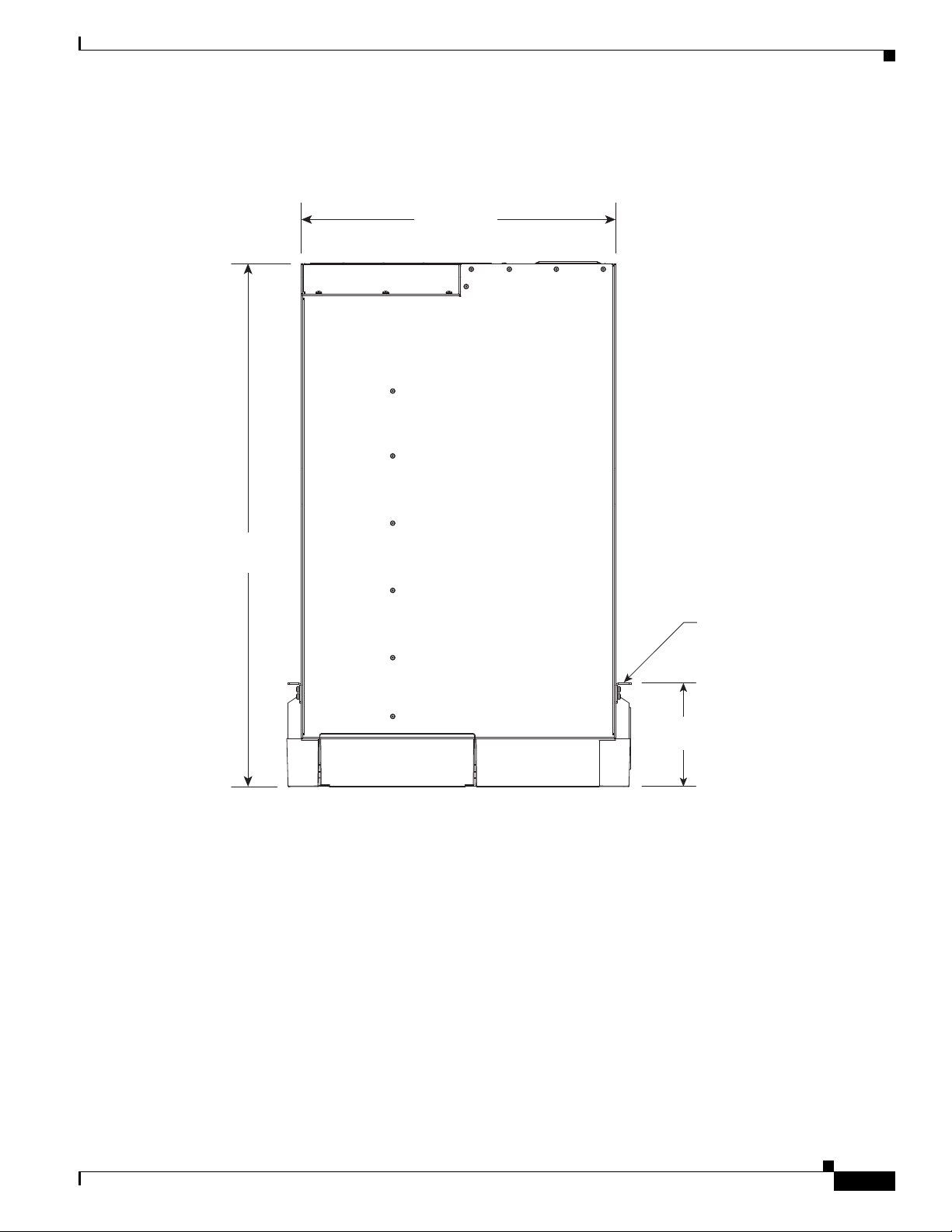
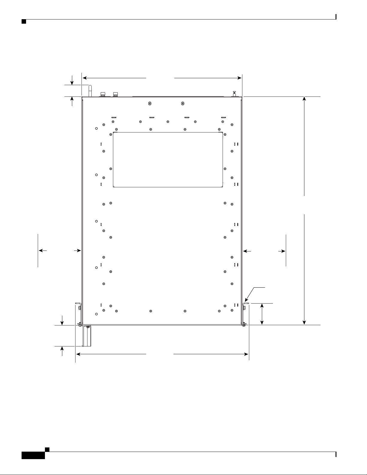
Figure 1-8 shows the top-down view dimensions of the Cisco ASR 9010 Router.
Figure 1-9 shows the top-down view dimensions of the Cisco ASR 9006 Router.
Figure 1-10 shows the top-down view dimensions of the Cisco ASR 9904 Router.
Figure 1-11 shows the top-down view dimensions of the Cisco ASR 9922 Router.
Figure 1-12 shows the top-down view dimensions of the Cisco ASR 9912 Router.
OL-17501-09
Cisco ASR 9000 Series Aggregation Services Router Overview and Reference Guide
1-9
Page 20
Rack-Mounting Considerations
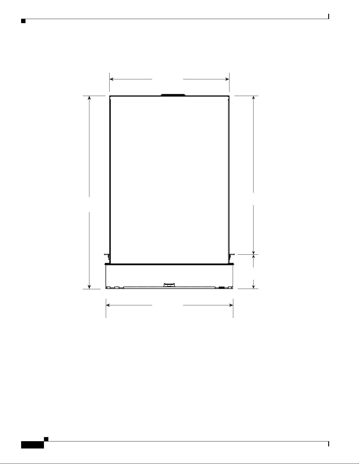
Figure 1-8 Cisco ASR 9010 Router Chassis Footprint Dimensions—Top Down View
Chapter 1 Overview and Physical Description
Rear of chassis
17.38 in
(44.15 cm)
28.93 in
(73.48 cm)
18.92 in
(48.06 cm)
Front of chassis
23.21 in
(58.95 cm)
5.04 in
(12.80 cm)
243432
1-10
Cisco ASR 9000 Series Aggregation Services Router Overview and Reference Guide
OL-17501-09
Page 21
Chapter 1 Overview and Physical Description
243430
Rear of chassis
Front of chassis
28.93 in
(73.48 cm)
17.38 in
(44.15 cm)
5.73 in
(14.55 cm)
Rack
mounting
surface
Figure 1-9 Cisco ASR 9006 Router Chassis Footprint Dimensions—Top Down View
Rack-Mounting Considerations
OL-17501-09
Cisco ASR 9000 Series Aggregation Services Router Overview and Reference Guide
1-11
Page 22
Rack-Mounting Considerations
Figure 1-10 Cisco ASR 9904 Router Chassis Footprint Dimensions—Top Down View
2.45 in
(6.22 cm)
Chapter 1 Overview and Physical Description
Rear of chassis
17.57 in
(44.64 cm)
6.00 in
(15.24 cm)
2.282 in
(5.79 cm)
18.97 in
(48.19 cm)
Front of chassis
25.02 in
(63.54 cm)
6.00 in
(15.24 cm)
Rack
mounting
surface
2.45 in
(6.22 cm)
351294
1-12
Cisco ASR 9000 Series Aggregation Services Router Overview and Reference Guide
OL-17501-09
Page 23
Chapter 1 Overview and Physical Description
343945
Rear of chassis
Front of chassis
5.05 in
(13.97 cm)
17.60 in
(44.70 cm)
30.11 in
(76.48 cm)
22 in
(55.88 cm)
Figure 1-11 Cisco ASR 9922 Router Chassis Footprint Dimensions—Top Down View
Rack-Mounting Considerations
OL-17501-09
Cisco ASR 9000 Series Aggregation Services Router Overview and Reference Guide
1-13
Page 24
Rack-Mounting Considerations
303667
Rear of chassis
Front of chassis
17.60 in
(44.70 cm)
29.44 in
(74.78 cm)
18.97 in
(48.18 cm)
22 in
(55.88 cm)
Figure 1-12 Cisco ASR 9912 Router Chassis Footprint Dimensions—Top Down View
Chapter 1 Overview and Physical Description
Chassis Slots
All Cisco ASR 9010 Router chassis line cards and RSP cards are front-facing and mounted vertically,
with ejector levers and captive screws at the top and bottom of each card.
All Cisco ASR 9006 Router and Cisco ASR 9904 Router chassis line cards and RSP cards are
front-facing and mounted horizontally, with ejector levers and captive screws at the left and right ends
of each card.
All Cisco ASR 9922 Router chassis RP, FC, and line cards are front-facing and mounted vertically, with
ejector levers and captive screws at the top and bottom of each card.
1-14
Cisco ASR 9000 Series Aggregation Services Router Overview and Reference Guide
OL-17501-09
Page 25

Chapter 1 Overview and Physical Description
All Cisco ASR 9912 Router chassis RP, FC, and line cards are front-facing and mounted vertically, with
ejector levers and captive screws at the top and bottom of each card.
The chassis components include:
• Two RSP cards in the Cisco ASR 9010 Router, Cisco ASR 9006 Router, and
Cisco ASR 9904 Router.
• Two RP and seven FC cards in the Cisco ASR 9922 Router and Cisco ASR 9912 Router
• Ethernet line cards
–
Cisco ASR 9010 Router—Up to eight
–
Cisco ASR 9006 Router—Up to four
–
Cisco ASR 9904 Router—Up to two
–
Cisco ASR 9922 Router—Up to twenty
–
Cisco ASR 9912 Router—Up to ten
• Backplane(s)
–
Cisco ASR 9010 Router—One
–
Cisco ASR 9006 Router—One
–
Cisco ASR 9904 Router—One
Rack-Mounting Considerations
–
Cisco ASR 9922 Router—Two
–
Cisco ASR 9912 Router—One
• BPID card(s)
–
Cisco ASR 9010 Router—One
–
Cisco ASR 9006 Router—One
–
Cisco ASR 9904 Router—One
–
Cisco ASR 9922 Router—Two
–
Cisco ASR 9912 Router—One
• Fan tray controllers
–
Cisco ASR 9010 Router—Two
–
Cisco ASR 9006 Router—Two
–
Cisco ASR 9904 Router—One
–
Cisco ASR 9922 Router—Four
–
Cisco ASR 9912 Router—Two
• Power trays
–
Cisco ASR 9010 Router—Two AC power trays in AC-powered systems or two DC power trays
in DC-powered systems
–
Cisco ASR 9006 Router—One AC power tray in AC-powered systems or one DC power tray in
DC-powered systems
OL-17501-09
–
Cisco ASR 9904 Router—One AC power tray in AC-powered systems or one DC power tray in
DC-powered systems
–
Cisco ASR 9922 Router—Four AC power trays in AC-powered systems or four DC power trays
in DC-powered systems
Cisco ASR 9000 Series Aggregation Services Router Overview and Reference Guide
1-15
Page 26
Rack-Mounting Considerations
242979
–
Cisco ASR 9912 Router—Three AC power trays in AC-powered systems or three DC power
trays in DC-powered systems
Note The line card slots are dedicated to only line cards; RSP/RP/FC cards cannot occupy these slots. The
RSP/RP/FC slots are dedicated to only RSP/RP/FC cards; line cards cannot occupy these slots. A keying
mechanism keeps line cards from entering RSP/RP/FC slots and RSP/RP/FC cards from entering line
card slots; the keying mechanism pins engage before the card alignment pins engage.
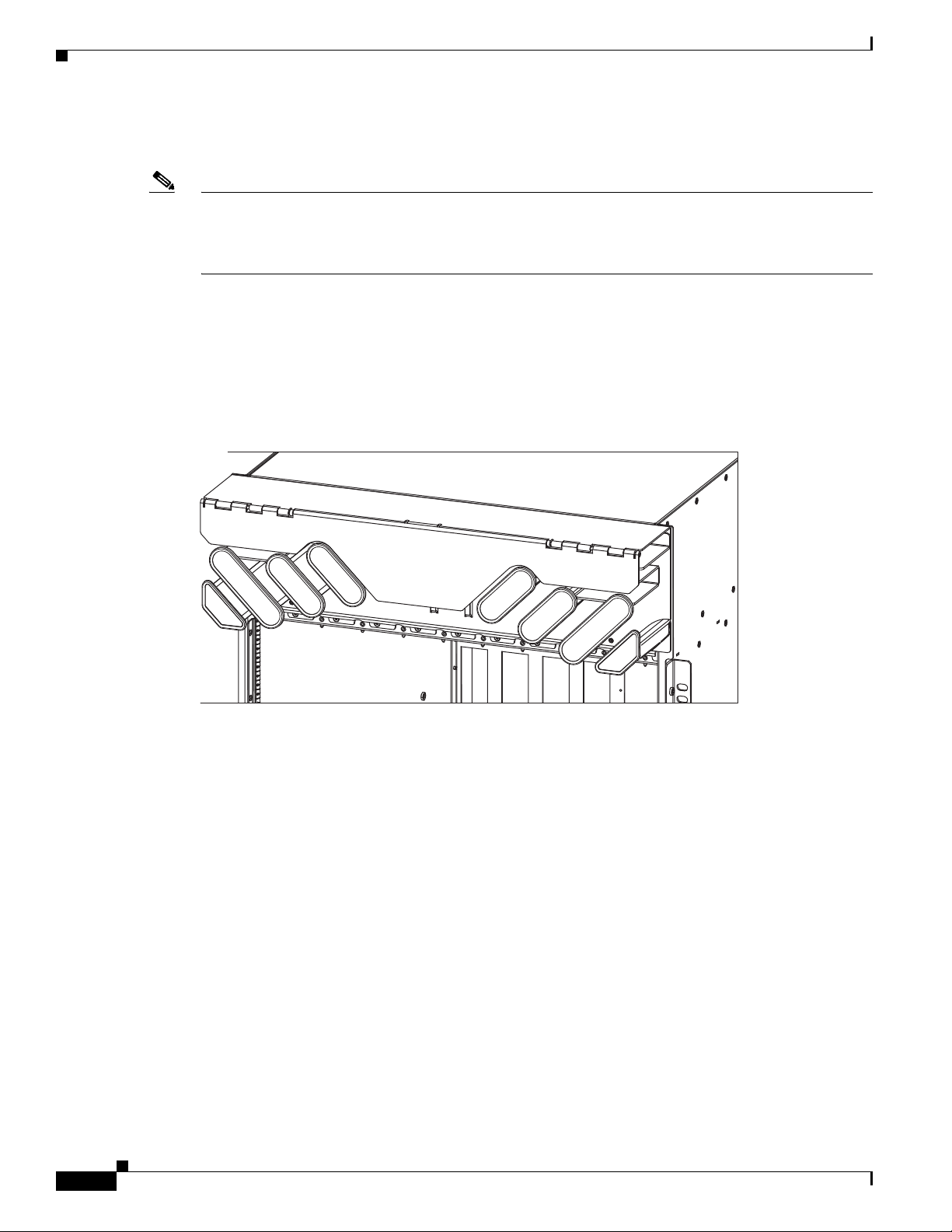
Fiber and Interface Cable Management
Figure 1-13 shows how card interface cables are managed at the front of the Cisco ASR 9010 Router chassis
using a cable management tray.
Figure 1-13 Cable Management Tray
Chapter 1 Overview and Physical Description
1-16
The cable management tray is located above the card cage (the Cisco ASR 9922 Router and
Cisco ASR 9912 Router have an additional cable management tray below the bottom card cage) and does
not interfere with the insertion or removal of cards. A hinged cover at the top of the tray can be raised
for ease of access for routing cables.
Line cards and RSP/RP cards share the same cable management tray. Cables to a card must be
disconnected before its removal (this does not affect adjacent cards). Removal of a line card or RSP/RP
card does not require removal or adjustment of cables other than those associated with the card itself.
A cable management bend radius of 1.5 inches (3.81 cm) is accommodated. Line card slots at the
extreme ends of the cable management trays use space outside of the chassis width to accommodate the
1.5-inch (3.81-cm) radii due to limited space per slot.
Space for the fiber bend radii and strain relief is 3.75 inches (9.53 cm) in front of the faceplate.
Figure 1-14 shows how the fiber and cables are routed upward away from slot number labels. Therefore slot
number labels, located at the lower part of the card cage, are not obscured by the cables.
Cisco ASR 9000 Series Aggregation Services Router Overview and Reference Guide
OL-17501-09
Page 27
Chapter 1 Overview and Physical Description
242895
Figure 1-14 Fiber/Cable Routing in the Cisco ASR 9010 Router
Rack-Mounting Considerations
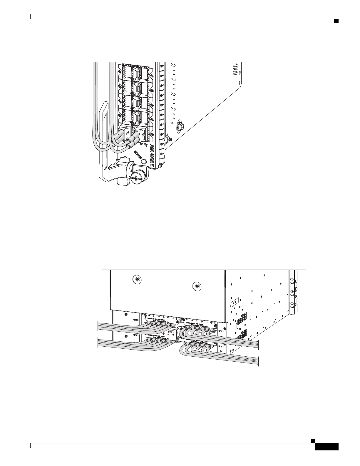
Routing of DC Power Tray Source Cables
Power cables are located in the rear. The A and B source feeds to the DC power supply modules are
separated so the cables route to opposite sides of the chassis. A cable tie down point is provided.
Figure 1-15 shows the DC power cable routing on the power trays.
Figure 1-15 Routing of DC Power Tray Source Cables
242894
OL-17501-09
Cisco ASR 9000 Series Aggregation Services Router Overview and Reference Guide
1-17
Page 28
Rack-Mounting Considerations
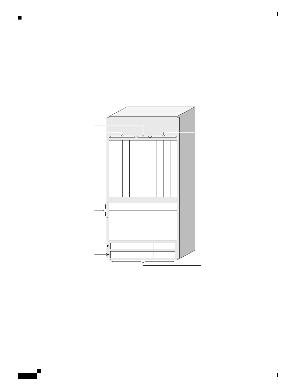
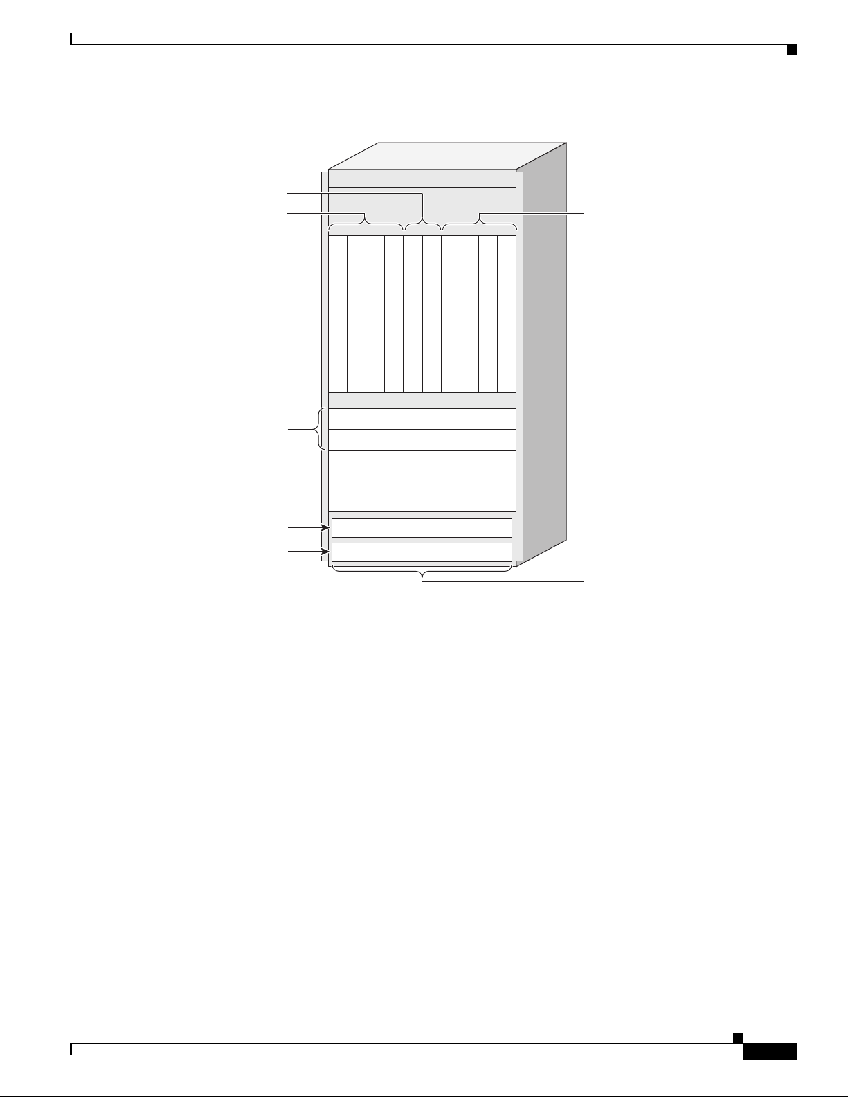
Slot Numbering and Marking
All card slots are clearly numbered. Labels identifying slots are visible from the front of the chassis and
are clearly numbered below each slot. As mentioned previously, fiber and cables are routed upward and
do not obscure the slot ID labels.
Figure 1-16 shows slot ID numbering for the Cisco ASR 9010 Router with version 1 power trays.
Figure 1-17 shows slot ID numbering for the Cisco ASR 9010 Router with version 2 power trays.
Figure 1-16 Cisco ASR 9010 Router Router Slot ID Numbering—Version 1 Power Trays
RSP cards
Line cards 0-3
Chapter 1 Overview and Physical Description
Line cards 4-7
0123 4567
Fan trays
Power shelves
PS0
PS1
RSP0
Line card
Line card
Line card
Slot 0
Slot 1
Slot 2
Front air intake
M0 M1 M2
M0 M1 M2
RSP1
Line card
Slot 3
Slot 4
Slot 5
FT0
FT1
Line card
Slot 6
Line card
Line card
Line card
Slot 7
Slot 8
Slot 9
242689
Power modules
1-18
Cisco ASR 9000 Series Aggregation Services Router Overview and Reference Guide
OL-17501-09
Page 29
Chapter 1 Overview and Physical Description
Figure 1-17 Cisco ASR 9010 Router Slot ID Numbering—Version 2 Power Trays
RSP cards
Line cards 0-3
0123 4567
RSP0
Line card
Line card
Line card
Slot 0
Slot 1
Slot 2
RSP1
Line card
Slot 3
Slot 4
Slot 5
Line card
Line card
Line card
Slot 6
Slot 7
Slot 8
Rack-Mounting Considerations
Line cards 4-7
Line card
Slot 9
Fan trays
Power shelves
PS0
PS1
FT0
FT1
Front air intake
M0 M1 M2
M0 M1 M2M3M3
284401
Power modules
OL-17501-09
Cisco ASR 9000 Series Aggregation Services Router Overview and Reference Guide
1-19
Page 30
Rack-Mounting Considerations
243377
Line card 3
FT0
M0 M1 M2
FT1
Line card 2
Line card 1
Line card 0
RSP1
RSP0
Slot 5
Slot 4
Slot 3
Slot 2
Slot 1
Slot 0
Power shelf
Power modules
Fan trays
RSP cards
Line cards
284273
Line card 3
FT0
M0 M1 M2 M3
FT1
Line card 2
Line card 1
Line card 0
RSP1
RSP0
Slot 5
Slot 4
Slot 3
Slot 2
Slot 1
Slot 0
Power shelf
Power modules
Fan trays
RSP cards
Line cards
Figure 1-18 shows slot ID numbering for the Cisco ASR 9006 Router with the version 1 power tray.
Figure 1-19 shows slot ID numbering for the Cisco ASR 9006 Router with the version 2 power tray.
Figure 1-18 Cisco ASR 9006 Router Slot ID Numbering—Version 1 Power Tray
Chapter 1 Overview and Physical Description
Figure 1-19 Cisco ASR 9006 Router Slot ID Numbering—Version 2 Power Tray
1-20
Cisco ASR 9000 Series Aggregation Services Router Overview and Reference Guide
OL-17501-09
Page 31

Chapter 1 Overview and Physical Description
390180
M0 M1 M2 M3
Line card 1
RSP1
RSP0
Slot 3
Line card 0Slot 0
Slot 2
Slot 1
Power shelf
Power modules
RSP cards
Line card 1
Single fan tray
(rear view)
Line card 0
Figure 1-20 shows slot ID numbering for the Cisco ASR 9904 Router with the version 2 power tray.
Figure 1-20 Cisco ASR 9904 Router Slot ID Numbering—Version 2 Power Tray
Rack-Mounting Considerations
Figure 1-21 shows slot numbering for the Cisco ASR 9922 Router with version 2 power trays.
Figure 1-22 shows slot numbering for the Cisco ASR 9912 Router with version 2 power trays.
Note For the Cisco ASR 9922 Router, line cards must be installed upside down in slots 10 through 19 of the
bottom card cage, whereas in slots 0 though 9 of the top card cage, the line cards are installed right side
up.
OL-17501-09
Cisco ASR 9000 Series Aggregation Services Router Overview and Reference Guide
1-21
Page 32

Rack-Mounting Considerations
302423
M3M2M1M0
M7M6M5M4
M11M10M9M8
M15M14M13M12
Power shelves/trays
PS0
Power modules
PS1
PS2
PS3
Fan trays
Fan trays
Line cards
Line cards
LC0
LC1
LC2
LC3
LC4
LC5
LC6
LC7
LC8
LC9
Slot 0
Slot 1
Slot 2
Slot 3
Slot 4
Slot 5
Slot 6
Slot 7
Slot 8
Slot 9
FT0
FT1
FT2
FT3
LC19
LC18
LC17
LC16
LC15
LC14
LC13
LC12
LC11
LC10
Slot 19
Slot 18
Slot 17
Slot 16
Slot 15
Slot 14
Slot 13
Slot 12
Slot 11
Slot 10
RP0
FC0
FC6
RP1
FC1
FC2
FC3
FC4
FC5
Chapter 1 Overview and Physical Description
Figure 1-21 Cisco ASR 9922 Router Components and Slot Numbering
1-22
Cisco ASR 9000 Series Aggregation Services Router Overview and Reference Guide
OL-17501-09
Page 33

Chapter 1 Overview and Physical Description
303672
M3M2M1M0
M7M6M5M4
M11M10M9M8
PS0
Power modules
PS1
PS2
Fan trays
(rear instertion)
Line cards
LC0
LC1
LC2
LC3
LC4
LC5
LC6
LC7
LC8
LC9
Slot 0
Slot 1
Slot 2
Slot 3
Slot 4
Slot 5
Slot 6
Slot 7
Slot 8
Slot 9
FT0
FT1
RP0
FC0
FC6
RP1
FC1
FC2
FC3
FC4
FC5
Power shelves/trays
Figure 1-22 Cisco ASR 9912 Router Components and Slot Numbering
Rack-Mounting Considerations
Power Module Hardware and Software Identification
OL-17501-09
The power modules have software IDs that differ from the hardware ID labels on the chassis shown in
the figures above. Table 1-1 lists the hardware IDs and the corresponding software IDs for the power
modules.
Table 1-1 Power Module Hardware and Software IDs
Hardware ID Software ID
PS0 M0 PM0
PS0 M1 PM1
PS0 M2 PM2
PS0 M3 PM3
PS1 M0 PM4
Cisco ASR 9000 Series Aggregation Services Router Overview and Reference Guide
1-23
Page 34

Route Switch Processor and Route Processor Cards
Table 1-1 Power Module Hardware and Software IDs
Hardware ID Software ID
PS1 M1 PM5
PS1 M2 PM6
PS1 M3 PM7
PS2 M0 PM8
PS2 M1 PM9
PS2 M2 PM10
PS2 M3 PM11
PS3 M0 PM12
PS3 M1 PM13
PS3 M2 PM14
PS3 M3 PM15
Chapter 1 Overview and Physical Description
Route Switch Processor and Route Processor Cards
The RSP card is the main control and switch fabric element in the Cisco ASR 9010 Router, and
Cisco ASR 9006 Router, and Cisco ASR 9904 Router. To provide redundancy, there can be two RSP
cards in each router, one as the active control RSP and the other as the standby RSP. The standby RSP
takes over all control functions should the active RSP fail.
The RP card is the main control element in the Cisco ASR 9922 Router and Cisco ASR 9912 Router.
The RP card provides centralized chassis control, management, and data-plane switching. To provide
redundancy, there are two RP cards in each router, one as the active control RP and the other as the
standby RP. The standby RP takes over all control functions should the active RP fail.
On the Cisco ASR 9922 Router and Cisco ASR 9912 Router, the switch fabric has been moved to FC
cards.
RSP Front Panel and Access Ports
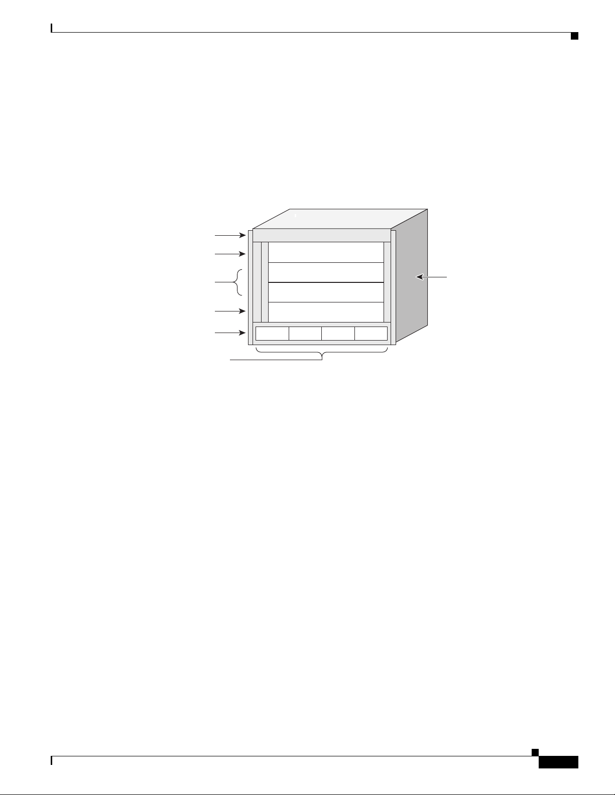
System alarms reside on the RSP. Alarms consist of visual indicators with three levels: Critical (red),
Major (red), and Minor (yellow). There is a console interface for remote viewing of alarms and fault
information. The RSP has the following information and alarm LEDs and connectors:
• One external Compact Flash type I/II (not on RSP-440)
• Two EIA/TIA-232 RJ232 serial RJ-45 ports—one each for Console and Auxiliary modem ports, with
Manufacturing Test connections to the backplane
• Two dual-speed 100/1000 Mbit Ethernet Management ports
• One 4 character 5x7 LED dot matrix display and discrete status LEDs
1-24
• Alarm Cut Off (ACO) and Lamp Test momentary push buttons
• Two RJ-45 Sync timing ports with Link and Fault LEDs built into the RJ-45
• Alarm Output DB9 port with three alarm outputs
Cisco ASR 9000 Series Aggregation Services Router Overview and Reference Guide
OL-17501-09
Page 35

Chapter 1 Overview and Physical Description
242983
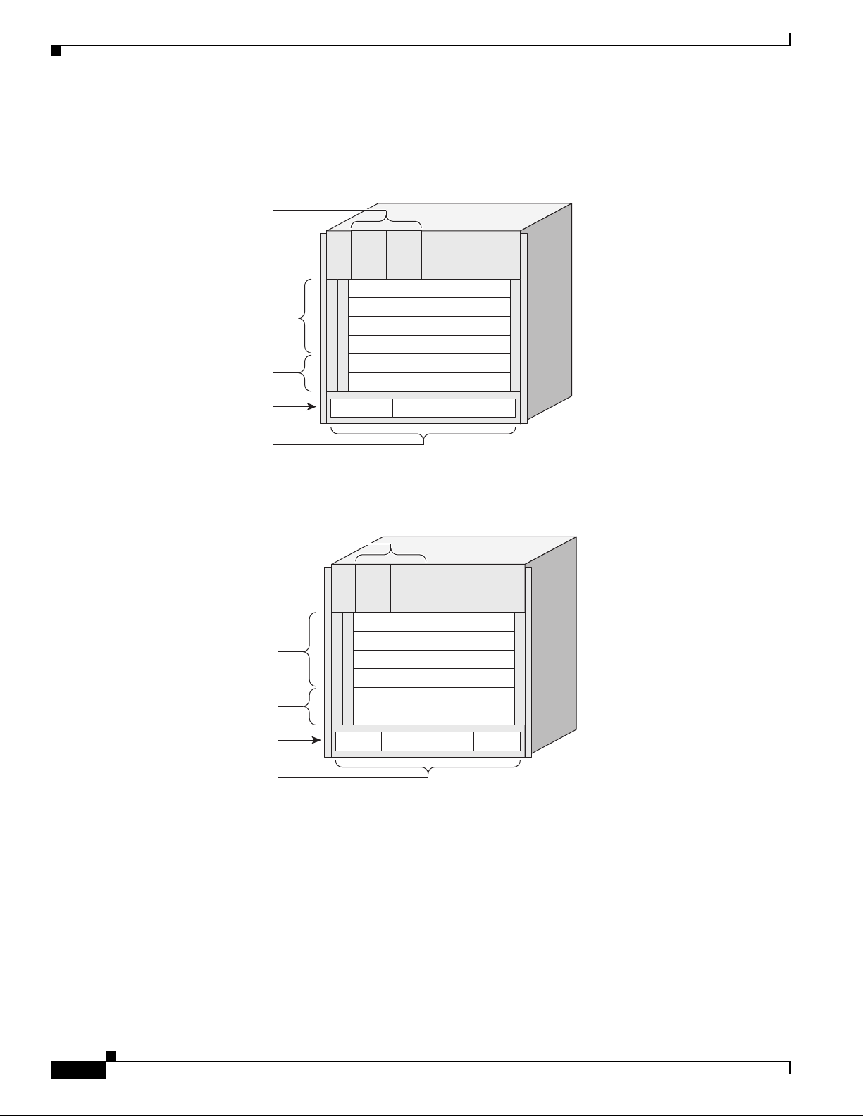
Figure 1-23 shows the front panel of the RSP card.
Figure 1-23 RSP Card Front Panel
Route Switch Processor and Route Processor Cards
OL-17501-09
Cisco ASR 9000 Series Aggregation Services Router Overview and Reference Guide
1-25
Page 36

Route Switch Processor and Route Processor Cards
Figure 1-24 shows the front panel of the RSP-440 card.
Figure 1-24 RSP-440 Card Front Panel
BITS J211 BITS J211
SYNC 0 SYNC 1
1
Chapter 1 Overview and Physical Description
2
3
4
5
6
7
8
9
10
11
12
SFP + 1
LINK ACT
10MHz 1PPS
BITS J.211
BITS J.211
ACO
LAMP
TEST
SSD
CRIT
FAIL
ACO
FC FAULT
MAJ
MIN
GPS
SYNC
A9K-RSP440-SE
IEEE 1588 ICS0
ICS1/TOD
GPS INTERFACE
ALARM OUT
MGT LAN 0
CONSOLEMGT LAN 1
AUX
SFP + 0
330841
1 SYNC (BITS/J.211) ports 7 External USB port
2 SFP/SFP+ ports 8 Management LAN ports
3 IEEE 1588 port 9 CONSOLE and AUX ports
4 ToD por t 10 Alarm Cutoff (ACO) and Lamp Test push buttons
5 10 MHz and 1 PPS indicators 11 Eight discrete LED indicators
6 Alarm Out DB9 connector 12 LED matrix display
Cisco ASR 9000 Series Aggregation Services Router Overview and Reference Guide
1-26
OL-17501-09
Page 37

Chapter 1 Overview and Physical Description
RP Front Panel and Access Ports
System alarms reside on the RP. Alarms consist of visual indicators with three levels: Critical (red),
Major (red), and Minor (amber). There is a console interface for remote viewing of alarms and fault
information. The RP front panel has the following information and alarm LEDs and connectors:
• Two BITS RJ-45 Sync timing ports
• Two 10 GE SFP/SFP+ ports
• IEEE1588 RJ-45 Timestamp port
• RS232/422 GPS TOD RJ-45 port for system timing input
• 10 MHz and 1 PPS clock input SMB ports
• Alarm Output DB9 port with three alarm outputs
• External USB2, class-A port
• Two RJ-45 100/1000 Mbit Ethernet Management ports
• RJ-45 Console port
• RJ-45 Auxiliary (AUX) port
• Alarm Cut Off (ACO) and Lamp Test momentary push buttons
• RP Discrete Status LEDs
Route Switch Processor and Route Processor Cards
–
SSD LED
–
FC Fault LED
–
GPS LED
–
Critical Alarm LED (red)
–
Major Alarm LED (red)
–
Minor Alarm LED (amber)
–
Power Fail LED
–
ACO LED (amber)
–
SYNC LED (green and amber)
• One 4-character 5x7 LED dot-matrix display
Figure 1-25 shows the front panel of the RP card.
OL-17501-09
Cisco ASR 9000 Series Aggregation Services Router Overview and Reference Guide
1-27
Page 38

Route Switch Processor and Route Processor Cards
7
3
4
5
8
13
1
9
10
12
11
2
6
344073
Figure 1-25 RP Card Front Panel
Chapter 1 Overview and Physical Description
1 SYNC (BITS/J.211) ports 8 External USB port
2 SFP/SFP+ ports 9 Management LAN ports
3 IEEE 1588 port 10 CONSOLE and AUX ports
4 Inter-chassis nv Sync0 11 Alarm Cutoff (ACO) and Lamp Test push buttons
5 Inter-chassis nv Sync1 GPS ToD 12 Nine discrete LED indicators
6 10 MHz and 1 PPS indicators 13 LED matrix display
7 Alarm Out DB9 connector
Figure 1-26 shows the RP card.
1-28
Cisco ASR 9000 Series Aggregation Services Router Overview and Reference Guide
OL-17501-09
Page 39

Chapter 1 Overview and Physical Description
Figure 1-26 RP Card
Route Switch Processor and Route Processor Cards
Management Features
Two management LAN ports (MGT LAN 0, MGT LAN 1) are provided on the RSP/RP front panel.
These are triple-speed RJ-45 connectors for use as out-of-band management ports.
An Auxiliary (AUX) port and Console port are also provided on the RSP/RP front panel. These are
EIA/TIA-232 (also known as RS-232) asynchronous serial ports for connecting external devices to
monitor and manage the system.
The RSP/RP card front panel also has a two synchronization (SYNC) timing ports that can be configured
as BITS or J.211 ports. These ports provide connections for external timing and synchronization sources.
Alarm Connector
Each RSP/RP card drives a set of three alarm output contacts. Alarm circuitry on the RSP/RP card
activates dry contact closures that are accessible through a nine-pin connector on the RSP/RP faceplate.
Both normally open and normally closed contacts are available.
302406
OL-17501-09
Cisco ASR 9000 Series Aggregation Services Router Overview and Reference Guide
1-29
Page 40

Fabric Controller Card
Serviceability
RSP/RP cards can be inserted or removed when adjacent (cabled) RSP/RP or line cards are installed.
Compact Flash is serviceable without the need to remove the RSP card. Servicing the hard drive requires
removal of the RSP/RP card.
RSP and RP Card Ejector Levers
Ejector levers are provided for inserting and removing the RSP/RP cards. The insertion and removal
force of the card ejector levers is about 16 lbs (7.27 kg). Longer ejector levers are provided for the
RSP/RP cards than for the line cards due to the higher pin count of the RSP/RP card.
Fabric Controller Card
On the Cisco ASR 9922 Router and Cisco ASR 9912 Router, the switch fabric has been moved to FC
cards.
The switch fabric is configured as a single stage of switching with multiple parallel planes. The switch
fabric is responsible for transporting packets from one line card to another but has no packet processing
capabilities. Each fabric plane is a single-stage, non-blocking, packet-based, store-and-forward switch.
To manage fabric congestion, the RP provides centralized Virtual Output Queue (VOQ) arbitration.
The switch fabric is capable of delivering 550-Gbps per line card slot. When five FC cards are installed
in the chassis, the switch fabric is 4+1 redundant. When all seven FC cards are installed in the chassis,
the switch fabric is 6+1 redundant. The switch fabric is fully redundant, with one copy of the fabric on
each FC, and each FC carries enough switching capacity to meet the chassis throughput specifications.
Chapter 1 Overview and Physical Description
1-30
Cisco ASR 9000 Series Aggregation Services Router Overview and Reference Guide
OL-17501-09
Page 41

Chapter 1 Overview and Physical Description
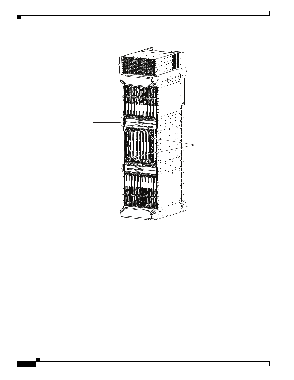
Figure 1-27 shows the FC card.
Figure 1-27 FC Card
Fabric Controller Card
OL-17501-09
302403
Figure 1-28 shows the front panel of the FC card. The front panel has a status LED, ejector levers, ejector
lever release buttons, and mounting screws.
Figure 1-28 FC Card Front Panel
302405
Cisco ASR 9000 Series Aggregation Services Router Overview and Reference Guide
1-31
Page 42

Ethernet Line Cards
FC Card Ejector Levers
Ejector levers are provided for inserting and removing the FC cards from the backplane connectors. The
insertion and removal force of the card ejector levers is about 16 lbs (7.27 kg). To release the ejector
levers, push in the ejector lever release buttons.
Note Once any ejector lever release button is pushed in, the FC card must by physically removed and
reinserted (OIR) to restart the FC card.
Ethernet Line Cards
This set of line cards for the Cisco ASR 9000 Series Routers is based on a single base card containing
the processors, fabric interface, power, and forwarding circuitry. Mounted on the base card are daughter
cards containing I/O circuitry.
• 40-port Gigabit Ethernet with SFP (small form-factor pluggable) optics
• 4-port 10-Gigabit Ethernet line rate card with XFP optics
Chapter 1 Overview and Physical Description
• 8-port 10-Gigabit Ethernet 2:1 oversubscribed card with XFP optics
• 8-port 10-Gigabit Ethernet 80-Gbps line rate card with XFP optics
• Combination 2-port 10-Gigabit Ethernet plus 20-port Gigabit Ethernet card with XFP and SFP
optics
• 16-port 10-Gigabit Ethernet oversubscribed card with SFP+ optics
• 24-port 10-GE DX Line Card, Packet Transport Optimized with SFP+ optics
• 24-port 10-GE DX Line Card, Service Edge Optimized with SFP+ optics
• 36-port 10-GE DX Line Card, Packet Transport Optimized with SFP+ optics
• 36-port 10-GE DX Line Card, Service Edge Optimized with SFP+ optics
• 2-port 100-GE DX Line Card, Packet Transport Optimized with CFP optics
• 2-port 100-GE DX Line Card, Service Edge Optimized with CFP optics
• 1-port 100-GE DX Line Card, Packet Transport Optimized with CFP optics
• 1-port 100-GE DX Line Card, Service Edge Optimized with CFP optics
• 80 Gigabyte Modular Line Card, Packet Transport Optimized
• 80 Gigabyte Modular Line Card, Service Edge Optimized
• 160 Gigabyte Modular Line Card, Packet Transport Optimized
• 160 Gigabyte Modular Line Card, Service Edge Optimized
• 20-port GE Modular Port Adapter (MPA) with SFP optics
1-32
• 8-port 10-GE MPA with SFP+ optics
• 4-port 10-GE MPA with XFP optics
• 2-port 10-GE MPA with XFP optics
• 2-port 40-GE MPA with QSFP+ optics
• 1-port 40-GE MPA with QSFP+ optics
Cisco ASR 9000 Series Aggregation Services Router Overview and Reference Guide
OL-17501-09
Page 43

Chapter 1 Overview and Physical Description
For line card installation information, see the Cisco ASR 9000 Series Aggregation Services Routers
For line card installation information, see:
Ethernet Line Card Installation Guide.
Cisco ASR 9000 Series Aggregation Services Routers Ethernet Line Card Installation Guide
In addition to the line cards listed here, a SPA Interface Processor (SIP) and Shared Port Adapters (SPA)
In addition to the line cards listed here, a SPA Interface Processor (SIP) and Shared Port Adapters (SPA)
are supported on the Cisco ASR 9000 Series Routers. For information about these components, see the
are supported on the Cisco ASR 9000 Series Routers. For information about these components, see:
Cisco ASR 9000 Aggregation Services Router SIP and SPA Hardware Installation Guide.
Cisco ASR 9000 Aggregation Services Router SIP and SPA Hardware Installation Guide
Line Card Front Panel and Access Ports
Line Card Front Panel and Access Ports
Each line card drives a set of three alarm output contacts, one set for each of Critical, Major, and Minor.
Each line card drives a set of three alarm output contacts, one set for each of Critical, Major, and Minor.
Alarm circuitry on the RSP/RP activates dry contact closures that are accessible through a nine-pin
Alarm circuitry on the RSP/RP activates dry contact closures that are accessible through a nine-pin
connector on the RSP/RP faceplate.
connector on the RSP/RP faceplate.
See the “Ethernet Line Cards” section on page 2-21 for a description of each line card’s front panel
See the “Ethernet Line Cards” section on page 2-21 for a description of each line card’s front panel
indicators and their meaning.
indicators and their meaning.
Line Card Serviceability
Line Card Serviceability
Line cards can be inserted or removed when adjacent (cabled) RSP or line cards are installed.
Line cards can be inserted or removed when adjacent (cabled) RSP or line cards are installed.
Power System
Line Card Ejector Levers
Line Card Ejector Levers
Ejector levers are provided for inserting and removing line cards from the backplane connectors.
Ejector levers are provided for inserting and removing line cards from the backplane connectors.
Insertion and removal force of the card ejector levers is about 16 lbs (7.27 kg).
Insertion and removal force of the card ejector levers is about 16 lbs (7.27 kg).
Power System
Power System
The Cisco ASR 9000 Series Routers can be powered with an AC or DC source power. The power system
The Cisco ASR 9000 Series Routers can be powered with an AC or DC source power. The power system
provides power for the cards and fan trays.
provides power for the cards and fan trays.
The power system is based on a distributed power architecture centered around a –54 VDC printed
The power system is based on a distributed power architecture centered around a –54 VDC printed
circuit power bus on the system backplane.
circuit power bus on the system backplane.
The –54 VDC system backplane power bus can be sourced from one of two options:
The –54 VDC system backplane power bus can be sourced from one of two options:
• AC systems—AC/DC bulk power supply tray connected to the user 200 to 240 VAC +/- 10 percent
• AC systems—AC/DC bulk power supply tray connected to the user 200 to 240 VAC +/- 10 percent
(180 to 264 VAC) source
(180 to 264 VAC) source
• DC systems—DC/DC bulk power supply tray connected to the user Central Office DC battery
• DC systems—DC/DC bulk power supply tray connected to the user Central Office DC battery
source –48 VDC/–60 VDC (–54 VDC nominal)
source –48 VDC/–60 VDC (–54 VDC nominal)
DC output power from each power tray is connected to the router by two power blades that mate to the
DC output power from each power tray is connected to the router by two power blades that mate to the
power bus on the backplane. The system backplane distributes DC power through connectors on the
power bus on the backplane. The system backplane distributes DC power through connectors on the
backplane to each card and the fan trays. Each card has on-board DC–DC converters to convert the
backplane to each card and the fan trays. Each card has on-board DC–DC converters to convert the
–54 VDC from the distribution bus voltage to the voltages required by each particular card.
–54 VDC from the distribution bus voltage to the voltages required by each particular card.
OL-17501-09
Cisco ASR 9000 Series Aggregation Services Router Overview and Reference Guide
1-33
Page 44

Power System
242900
AC and DC Power Modules
Each AC or DC power tray houses up to four power modules.
• The AC and DC power trays in the Cisco ASR 9006 Router and Cisco ASR 9904 Router provide
N+1 redundancy.
• The AC power trays in the Cisco ASR 9010 Router, Cisco ASR 9922 Router, and Cisco ASR 9912
Router provide N+N redundancy. The DC power trays provide N+1 redundancy.
The power trays drive a single output bus that delivers –54 V to all cards and fan trays that are plugged
into the backplane.
Figure 1-29 shows a front view of six version 1 power modules in the Cisco ASR 9010 Router.
Figure 1-29 Front System View of Power Trays—Cisco ASR 9010 Router with Version 1 Power
Tr a y s
Chapter 1 Overview and Physical Description
1-34
Cisco ASR 9000 Series Aggregation Services Router Overview and Reference Guide
OL-17501-09
Page 45

Chapter 1 Overview and Physical Description
331401
Figure 1-30 shows a front view of eight version 2 power modules in the Cisco ASR 9010 Router.
Figure 1-30 Front System View of Power Trays—Cisco ASR 9010 Router with Version 2 Power
Power System
Tr a y s
The Cisco ASR 9006 Router and Cisco ASR 9904 Router are similar, except that:
• The Cisco ASR 9006 Router supports one power tray with up to three version 1 power modules or
four version 2 power modules.
• The Cisco ASR 9904 Router supports one power tray with up to four version 2 power modules (see
Figure 1-31).
Figure 1-31 Front System View of Power Tray—Cisco ASR 9904 Router with Version 2 Power Tray
390181
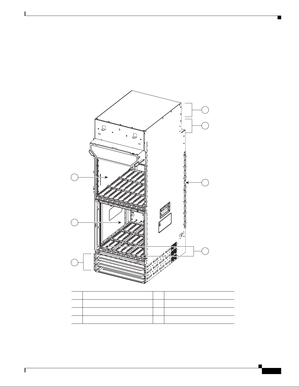
To operate the Cisco ASR 9922 Router on AC power, four AC power trays should be installed, each
•
with up to four power modules which are fed by a single-phase 220-V 20-A branch circuit. Eight
power modules are enough to power a fully-populated chassis. Sixteen power modules are required
for N+N redundancy. Fewer power modules can be used if the chassis is populated with fewer line
cards.
• To operate the Cisco ASR 9922 Router on DC power, four DC power trays should be installed, each
with up to four power modules which are fed by separate pairs of redundant –48-V 60-A branch
sources. Fifteen power modules are enough to power a fully-populated chassis. Sixteen power
modules are required for N+1 redundancy. Fewer power modules can be used if the chassis is
populated with fewer line cards.
OL-17501-09
Cisco ASR 9000 Series Aggregation Services Router Overview and Reference Guide
1-35
Page 46

Cooling System
344075
Chapter 1 Overview and Physical Description
• To operate the Cisco ASR 9912 Router on AC power, three AC power trays should be installed, each
with up to four power modules which are fed by a single-phase 220-V 20-A branch circuit. Six
power modules are enough to power a fully-populated chassis. Twelve power modules are required
for N+N redundancy. Fewer power modules can be used if the chassis is populated with fewer line
cards.
• To operate the Cisco ASR 9912 Router on DC power, three DC power trays should be installed, each
with up to four power modules which are fed by separate pairs of redundant –48-V 60A branch
sources. Eleven power modules are enough to power a fully-populated chassis. Twelve power
modules are required for N+1 redundancy. Fewer power modules can be used if the chassis is
populated with fewer line cards.
Figure 1-32 shows the front view of sixteen version 2 power modules installed in the
Cisco ASR 9922 Router.
Figure 1-32 Front System View of Power Trays —Cisco ASR 9922 Router with Version 2 Power
Tr a y s
Cooling System
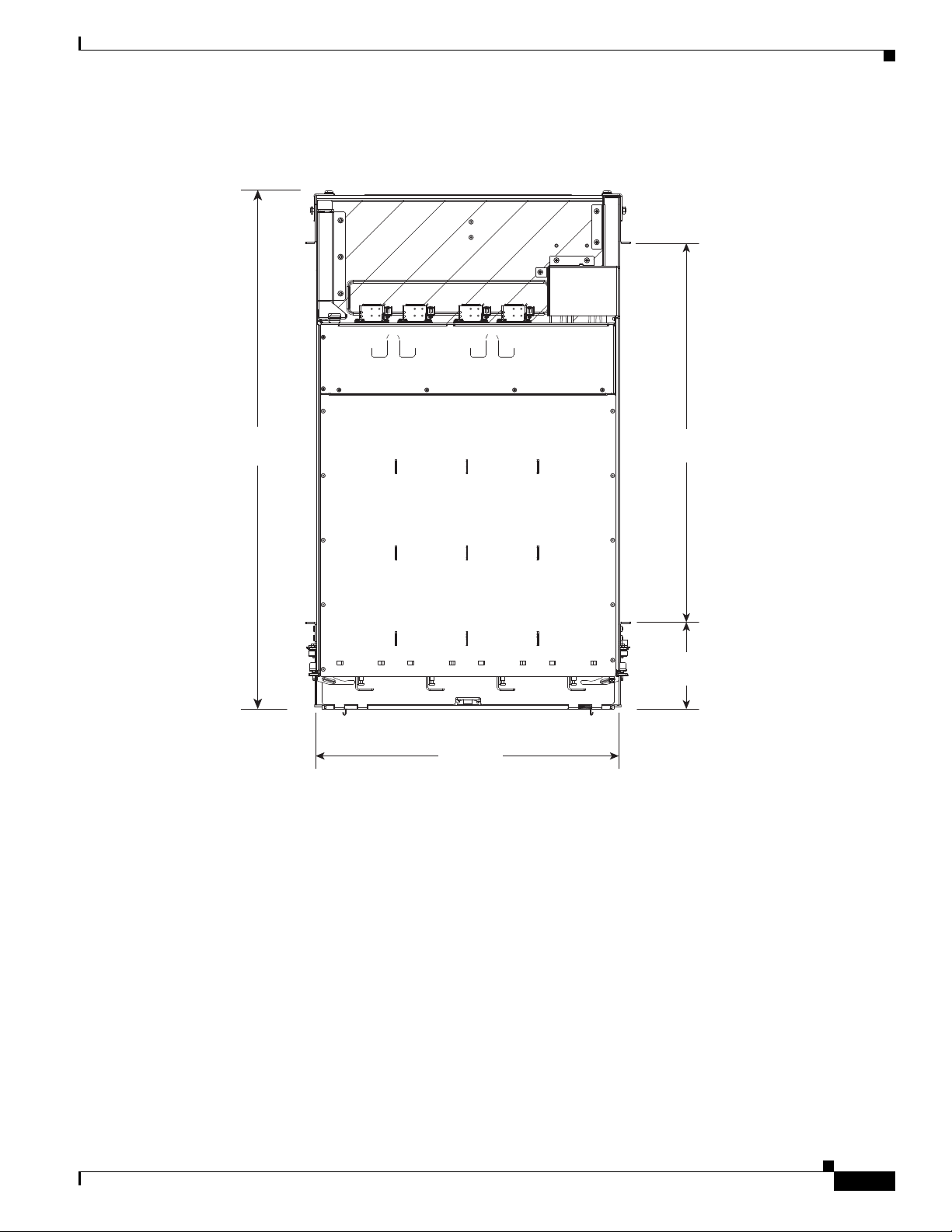
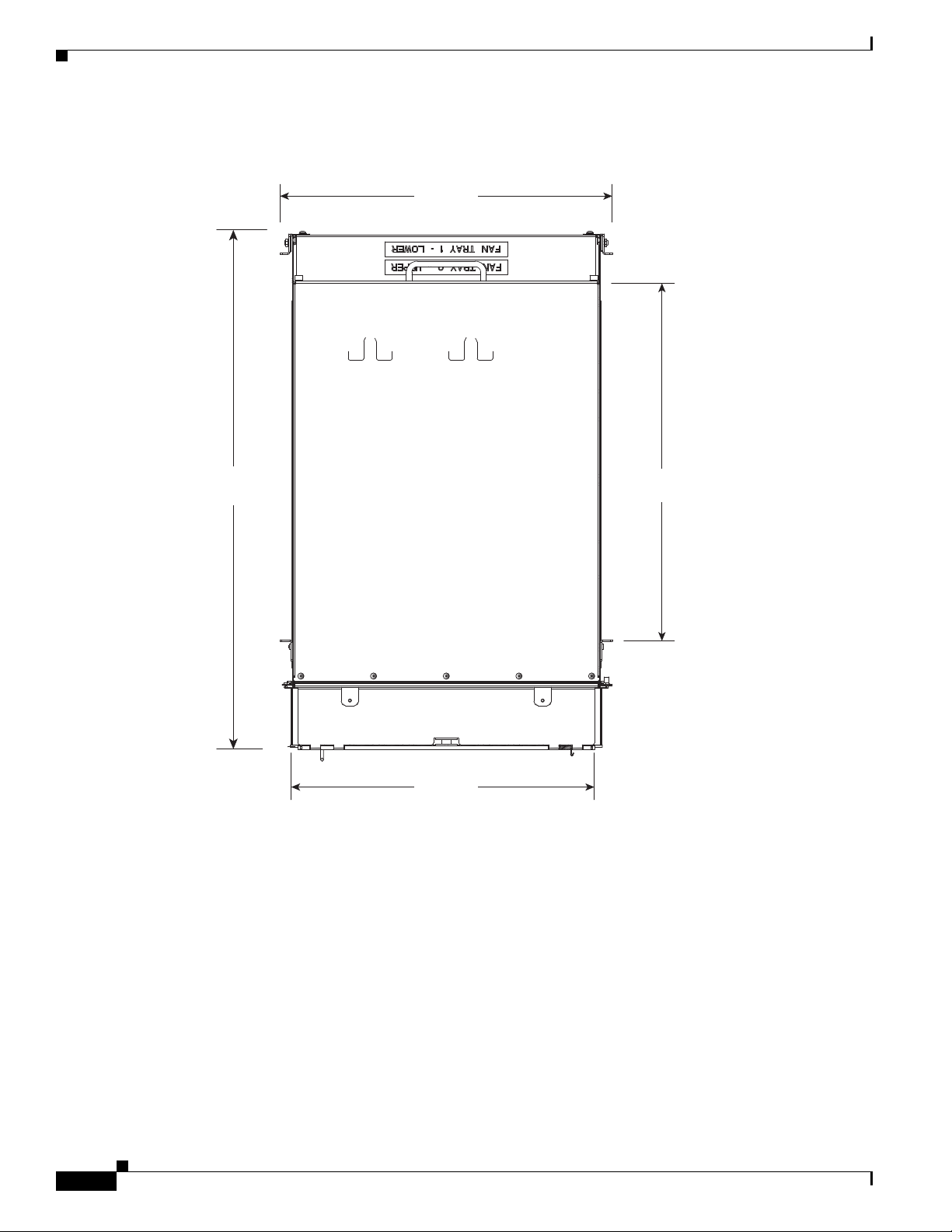
The Cisco ASR 9000 Series chassis is cooled by removable fan trays. The fan trays provide full
redundancy and maintain required cooling if a single fan failure should occur.
In the Cisco ASR 9010 Router, the two fan trays are located one above the other below the card cage and
are equipped with handles for easy removal.
In the Cisco ASR 9006 Router, the two fan trays are located above the card cage, left of center, and side
by side. They are covered by a fan tray door hinged at the bottom, which must be opened before
removing the fan trays.
In the Cisco ASR 9904 Router, a single fan tray is located in the rear, right side of the card cage and is
equipped with a handle for easy insertion.
In the Cisco ASR 9922 Router, the two top fan trays are located between the top and middle cages,
whereas the two bottom fan trays are located between the middle and bottom cages. The two bottom fan
trays are inserted upside down compared to the two top fan trays. In the Cisco ASR 9912 Router, the two
fan trays are located above the line card cage. Each fan tray holds 12 axial fans and includes a controller
that reduces the speed of the fans when the chassis temperature is within limits, thereby reducing the
generation of acoustic noise. The fan controller also senses and reports individual fan failures.
Cisco ASR 9000 Series Aggregation Services Router Overview and Reference Guide
1-36
OL-17501-09
Page 47

Chapter 1 Overview and Physical Description
Cooling Path
• The Cisco ASR 9010 Router chassis has a front-to-rear cooling path. The inlet is at the bottom front
of the chassis, and the exhaust is at the upper rear. Figure 2-64 shows the cooling path of the
Cisco ASR 9010 Router chassis.
• The Cisco ASR 9006 Router chassis has a side-to- top-to-rear cooling path. The inlet is at the right
side of the chassis, and the exhaust is at the upper rear. Figure 2-65 shows the cooling path of the
Cisco ASR 9006 Router chassis.
• The Cisco ASR 9904 Router has a side-to-side cooling path. Figure 2-66 shows the cooling path of
the Cisco ASR 9904 Router chassis. The inlet is at the right side of the chassis, and the exhaust is
at the left side.
If the router is installed in a 2-post 23-inch rack, air flow is circulated front-to-back. An optional air
baffle accessory kit (ASR-9904-BAFFLE=) is available for mounting the router chassis in this
configuration. For air baffle installation information, see:
Cisco ASR 9000 Series Aggregation Services Router Hardware Installation Guide
• The cages of the Cisco ASR 9922 Router chassis have a front-to-rear cooling path. The inlet is at
the front of the middle cage, and the exhaust is at the upper and lower rear. Figure 2-67 shows the
cooling path of the Cisco ASR 9922 Router chassis.
• The Cisco ASR 9912 Router chassis has a front-to-rear cooling path. The inlet is at the front of the
RP/FC card cage, and the exhaust is at the upper rear. Figure 2-68 shows the cooling path of the
Cisco ASR 9912 Router chassis.
Management and Configuration
Fan Trays
The Cisco ASR 9010 Router, Cisco ASR 9006 Router, and Cisco ASR 9912 Router contain two fan
trays for redundancy (see Figure 2-69, Figure 2-70, Figure 2-72). The Cisco ASR 9904 Router contains
a single fan tray for redundancy (see Figure 2-71). The Cisco ASR 9922 Router contains four fan trays
for redundancy (see Figure 2-72). The fan tray has an LED indicator to indicate fan tray status. If a fan
fails, it is possible to swap a single fan tray assembly while the system is operational. Fan tray removal
does not require removal of any cables.
Note Due to air leakage, the chassis should not be operated with any of the fan trays completely missing.
Replace any missing fan tray within five minutes. Any fan tray replacement should be performed when
the chassis is back to room temperature.
Management and Configuration
The Cisco ASR 9000 Series Routers run IOS XR software and use the system manageability
architecture of that operating system. The system management interfaces consist of the following three
protocols running on the Cisco ASR 9000 Series Routers:
• CLI—Command-line interface
• XML—Extensible Markup Language
• SNMP—Simple Network Management Protocol
By default, only CLI on the console is enabled.
OL-17501-09
Cisco ASR 9000 Series Aggregation Services Router Overview and Reference Guide
1-37
Page 48

Management and Configuration
Craft Works Interface (CWI), a graphical craft tool for performance monitoring, is embedded with the
Cisco IOS XR software and can be downloaded through the HTTP protocol. You can use CWI to edit
the router configuration file, open Telnet/SSH application windows, and create user-defined
applications.
Chapter 1 Overview and Physical Description
1-38
Cisco ASR 9000 Series Aggregation Services Router Overview and Reference Guide
OL-17501-09
Page 49

CHA P T ER
2
Functional Description
This chapter provides a functional description of the Cisco ASR 9000 Series Router, Route Switch
Processor (RSP) card, Route Processor (RP) card, Fabric Controller (FC) card, Ethernet line cards,
power and cooling systems, and subsystems such as management, configuration, alarms, and
monitoring.
• Router Operation, page 2-1
• Route Switch Processor Card, page 2-5
• Route Processor Card, page 2-8
• Fabric Controller Card, page 2-19
• Ethernet Line Cards, page 2-21
• Modular Line Cards, page 2-44
• Power System Functional Description, page 2-50
• Cooling System Functional Description, page 2-71
• System Management and Configuration, page 2-86
Router Operation
The ASR 9000 Series Routers are fully distributed routers that use a switch fabric to interconnect a
series of chassis slots, each of which can hold one of several types of line cards. Each line card in the
Cisco ASR 9000 Series has integrated I/O and forwarding engines, plus sufficient control plane
resources to manage line card resources. Two slots in the chassis are reserved for RSP/RP cards to
provide a single point of contact for chassis provisioning and management.
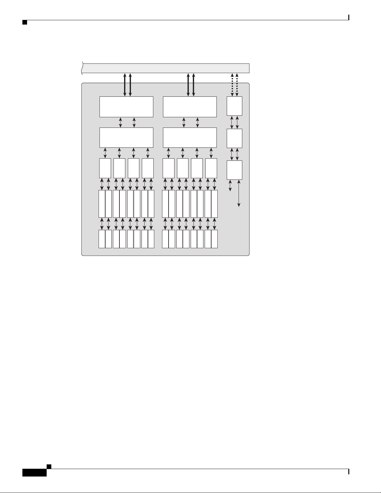
Figure 2-1 shows the platform architecture of the Cisco ASR 9010 Router, Cisco ASR 9006 Router, and
Cisco ASR 9904 Router.
OL-17501-09
Cisco ASR 9000 Series Aggregation Services Router Overview and Reference Guide
2-1
Page 50

Router Operation
RSP 0
RSP 1
Switch Fabric
Route Processor
Distributed
Forwarding
Line Card
Distributed
Forwarding
Line Card
Distributed
Forwarding
Line Card
RP 0
RP 1
Fabric Controller cards FC0 to FC6
Route Processor
Distributed
Forwarding
Line Card
344071
Distributed
Forwarding
Line Card
Distributed
Forwarding
Line Card
Chapter 2 Functional Description
Figure 2-1 Cisco ASR 9010 Router, Cisco ASR 9006 Router, and Cisco ASR 9904 Router Platform
Architecture
Figure 2-2 shows the platform architecture of the Cisco ASR 9922 Router and Cisco ASR 9912 Router.
Figure 2-2 Cisco ASR 9922 Router and Cisco ASR 9912 Router Platform Architecture
Figure 2-3 shows the major system components and interconnections of the
Cisco ASR 9000 Series Routers.
2-2
Cisco ASR 9000 Series Aggregation Services Router Overview and Reference Guide
OL-17501-09
Page 51

Chapter 2 Functional Description
RSP 0
Fabric
Chip
Fabric
Interface
Chip
System
Timing
GE
Switch
CPU
VOQ
Scheduler
40x1GE
Line Card
FPGA
Fabric
Interface
Chip
10 x
SFP
10 x
SFP
FPGA
10 x
SFP
NPU NPU NPU NPU
10 x
SFP
CPU
8x10GE 2:1
Oversubscribed
Line Card
FPGA
Fabri c
Interface
Chip
FPGA
CPU
4x10GE
Line Card
FPGA
Fabric
Interface
Chip
FPGA
GE PHYGE PHYGE PHY
CPU
RSP 1
Backplane
Backplane
Fabric
Chip
Fabric
Interface
Chip
System
Timing
GE
Switch
CPU
VOQ
Scheduler
Data Plane
Control Plane
10
GE
X
F
P
10
GE
X
F
P
10
GE
X
F
P
10
GE
X
F
P
10
GE
X
F
P
10
GE
X
F
P
10
GE
X
F
P
10
GE
X
F
P
10
GE
X
F
P
10
GE
X
F
P
10
GE
X
F
P
10
GE
X
F
P
247272
8x10GE 80G
Line Rate Card
GE
PHY
Fabric
Interface
Chip
FPGA
NPU
10
GE
X
F
P
NPU
10
GE
X
F
P
NPU
10
GE
X
F
P
NPU
10
GE
X
F
P
Fabric
Interface
Chip
FPGA
NPU
10
GE
X
F
P
NPU
10
GE
X
F
P
NPU
10
GE
X
F
P
NPU
10
GE
X
F
P
CPU
GE
SW
To
FPGAs
To
NPUs
2x10GE + 20x1GE
Combo Line Card
FPGAFPGA
NPU
10x
S
F
P
NPU
10x
S
F
P
NPU
10
GE
X
F
P
NPU
10
GE
X
F
P
GE
PHY
CPU
GE
SW
To
FPGAs
To
NPUs
Fabric
Interface
Chip
NPU NPU NPU NPU NPU NPU NPU NPU
Figure 2-3 Major System Components and Interconnections in the Cisco ASR 9000 Series Routers
Router Operation
OL-17501-09
Cisco ASR 9000 Series Aggregation Services Router Overview and Reference Guide
2-3
Page 52
Router Operation
Chapter 2 Functional Description
Figure 2-4 Additional System Components in the Cisco ASR 9000 Series Routers
Backplane
16x10GE SFP+
Line Card
Fabric
Interface
Chip
Fabric
Interface
Chip
GE
PHY
FPGA
NPU NPU NPU NPU
10G PHYSFP+
10G PHYSFP+
10G PHYSFP+
10G PHYSFP+
10G PHYSFP+
10G PHYSFP+
10G PHYSFP+
FPGA
NPU NPU NPU NPU
10G PHYSFP+
10G PHYSFP+
10G PHYSFP+
10G PHYSFP+
10G PHYSFP+
10G PHYSFP+
10G PHYSFP+
10G PHYSFP+
10G PHYSFP+
CPU
GE
SW
To
NPUs
To
FPGAs
248890
2-4
Cisco ASR 9000 Series Aggregation Services Router Overview and Reference Guide
OL-17501-09
Page 53

Chapter 2 Functional Description
Route Switch Processor Card
Figure 2-5 Major System Components and Interconnections in the Cisco ASR 9922 Series Router
RP 0
System
Timing
FC0
Interface
LC0
GE PHY Arbiter
Punt
Fabric
Interface
Chip
Control
CPU
Fabric
Interface
Chip
VOQ
Scheduler
Fabric
Interface
Chip
Fabric
Interface
Chip
VOQ
Scheduler
NPU
Optical
Module
CPU
GE
Switch
FC1
BPID
Control
Interface
Control
Interface
Arbiter
Backplanes
Fabric
Interface
Chip
Backplanes
LC19
GE PHY Arbiter
CPU
RP 1
System
Timing
Fabric
Interface
Chip
Punt
Fabric
Interface
Chip
Fabric
Interface
Chip
VOQ
Scheduler
NPU
Optical
Module
VOQ
Scheduler
FC6
Interface
BPID
CPU
GE
Switch
Control
Control
Interface
Fabric
Interface
Chip
Legend
Interface
EOBC
Arbitration Plane
Punt Path
Control Plane
Data Plane
Arbiter
Fabric
Chip
302428
Route Switch Processor Card
The RSP card is the main control and switch fabric element in the Cisco ASR 9010 Router,
Cisco ASR 9006 Router, and Cisco ASR 9904 Router chassis. The RSP card provides system control,
packet switching, and timing control for the system. To provide redundancy, there can be two RSP cards
in the system, one as the active control RSP and the other as the standby RSP. The standby RSP takes
over all control functions should the active RSP fail.
Figure 2-6 shows the front panel connectors and indicators of the RSP card.
Cisco ASR 9000 Series Aggregation Services Router Overview and Reference Guide
OL-17501-09
2-5
Page 54

Route Switch Processor Card
Figure 2-6 RSP Card Front Panel Indicators and Connectors
1
2
3
4
Chapter 2 Functional Description
LINK ACT LINK ACT
MGT LAN 0 MGT LAN 1 CONSOLE AUX SYNC 0 SYNC 1
BITS J.211 BITS J.211
ALARM OUT
COMPACT FLASH ACCESS
KEEP CLOSED
5
6
7
8
ACO
LAMP
TEST
FAIL
CRIT
MAJ
MIN
A9K-RSP-4G
SYNC
HDD
CF
ACO
243091
1 Management LAN ports 5 Compact Flash type I/II
2 CONSOLE and AUX ports 6 Alarm Cutoff (ACO) and LAMP TEST push buttons
3 SYNC (BITS/J.211) ports 7 Eight discrete LED indicators
4 Alarm Out DB9 connector 8 LED matrix display
2-6
Cisco ASR 9000 Series Aggregation Services Router Overview and Reference Guide
OL-17501-09
Page 55

Chapter 2 Functional Description
330841
SYNC 0 SYNC 1
SFP + 0
SFP + 1
IEEE 1588 ICS0
A9K-RSP440-SE
BITS J211 BITS J211
LINK ACT
ALARM OUT
ACO
LAMP
TEST
AUX
CONSOLEMGT LAN 1
BITS J.211
MGT LAN 0
BITS J.211
10MHz 1PPS
FC FAULT
MAJ
ACO
SSD
CRIT
FAIL
GPS
MIN
SYNC
GPS INTERFACE
ICS1/TOD
6
7
12
1
8
9
11
10
2
3
4
5
Figure 2-7 shows the front panel of the RSP-440 card.
Figure 2-7 RSP-440 Card Front Panel
Route Switch Processor Card
1 SYNC (BITS/J.211) ports 7 External USB port
2 SFP ports 8 Management LAN ports
3 IEEE 1588 port 9 CONSOLE and AUX ports
4 ToD port 10 Alarm Cutoff (ACO) and LAMP TEST push buttons
5 10MHz and 1PPS indicators 11 Eight discrete LED indicators
6 Alarm Out DB9 connector 12 LED matrix display
OL-17501-09
Cisco ASR 9000 Series Aggregation Services Router Overview and Reference Guide
2-7
Page 56

Route Processor Card
7
3
4
5
8
13
1
9
10
12
11
2
6
344073
Route Processor Card
The RP card is the main control element in the Cisco ASR 9922 Router and Cisco ASR 9912 Router
chassis. The switch fabric element has been moved to the FC cards. The RP card provides system control,
packet switching, and timing control for the system. To provide redundancy, there are two RP cards in
the system, one as the active control RP and the other as the standby RP. The standby RP takes over all
control functions should the active RP fail.
Figure 2-8 shows the front panel connectors and indicators of the RP card.
Figure 2-8 RP Card Front Panel Connectors and Indicators
Chapter 2 Functional Description
2-8
Cisco ASR 9000 Series Aggregation Services Router Overview and Reference Guide
OL-17501-09
Page 57

Chapter 2 Functional Description
Route Processor Card
1 SYNC (BITS/J.211) ports 8 External USB port
2 SFP/SFP+ ports 9 Management LAN ports
3 IEEE 1588 port 10 CONSOLE and AUX ports
4 Inter-chassis nv Sync0 11 Alarm Cutoff (ACO) and Lamp Test push buttons
5 Inter-chassis nv Sync1 GPS ToD 12 Nine discrete LED indicators
6 10 MHz and 1 PPS indicators 13 LED matrix display
7 Alarm Out DB9 connector
Front Panel Connectors
This section describes the front panel ports and connectors of the RSP/RP card.
Management LAN Ports
Console Port
Auxiliary Port
Alarm Out
Two dual-speed (100M/1000M) management LAN RJ-45 connectors are provided for use as out-of-band
management ports. The speed of the management LAN is autonegotiated.
The EIA/TIA-232 RJ-45 Console Port provides a data circuit-terminating equipment (DCE) interface for
connecting a console terminal. This port defaults to 9600 Baud, 8 data, no parity, 2 stop bits with flow
control none.
The EIA/TIA-232 RJ-45 auxiliary port provides a data circuit-terminating equipment (DCE) interface
that supports flow control. Use this port to connect a modem, a channel service unit (CSU), or other
optional equipment for Telnet management. This port defaults to 9600 Baud, 8 data, no parity, 1 stop bit
with software handshake.
Alarm circuitry on the RSP/RP activates dry contact closures that are accessible through the nine-pin
Alarm Out connector on the RSP/RP front panel. Each RSP/RP card drives a set of three alarm output
contacts. Both normally-open and normally-closed contacts are available.
Only the active RSP/RP drives the alarm outputs. Should a switchover to the standby RSP/RP occur, the
newly active RSP/RP drives the alarm outputs.
Synchronization Ports
The SYNC 0 and SYNC 1 ports are timing ports that can be configured as Building Integrated Timing
System (BITS) ports. A BITS port provides a connection for an external synchronization source to
establish precise frequency control at multiple network nodes, if required for your application. The
RSP/RP card contains a Synchronous Equipment Timing Source (SETS) that can receive a frequency
reference from an external BITS timing interface or from a clock signal recovered from any incoming
OL-17501-09
Cisco ASR 9000 Series Aggregation Services Router Overview and Reference Guide
2-9
Page 58

Route Processor Card
interface, such as a Gigabit Ethernet, 10-Gigabit Ethernet, or SONET interface. The RSP/RP SETS
circuit filters the received timing signal and uses it to drive an outgoing Ethernet interface or BITS output
port.
The timing port(s) can also be configured as J.211 or DTI ports. A DOCSIS Timing Interface (DTI) port is
used to connect to an external DTI server to synchronize timing and frequency across multiple routers.
The timing function allows precise synchronization of real-time clocks in a network for measurements
of network performance, for example, measuring delay across a VPN. The frequency reference acts like a
BITS input.
RP USB Port
The RP card has a single external Universal Serial Bus (USB) port. A USB flash memory device can be
inserted to load and transfer software images and files. This memory device can be used to turboboot the
system or as the installation source for Package Information Envelopes (PIE) and Software Maintenance
Up g rades (SM U ). This m e mory dev ice can a l so be use d for users ' data fi les, core files, and configurati o n
backups.
Front Panel Indicators
Chapter 2 Functional Description
The RSP card has eight discrete LED indicators and an LED dot-matrix display for system information.
The RSP-440 adds three USB-specific LEDs. The RP has nine discrete LED indicators and an LED
dot-matrix display for system information.
Table 2-1 shows the display definitions of the eight discrete LEDs on the RSP front panel and the three
RSP-440 specific USB LEDs.
Table 2-1 RSP and RSP-440 Discrete LED Display Definitions
Indicator (Label) Color Description
Power Fail
(FAIL)
Critical Alarm
(CRIT)
Major Alarm
(MAJ)
Minor Alarm
(MIN)
Synchronization
(SYNC)
Red Standby Power Fail LED. The LED is turned off by the Controller Area
Network (CAN) bus controller after it is up and running.
Off Standby power is normal.
Red Critical Alarm LED. A critical alarm has occurred.
Off
(Default after reset)
Red Major alarm LED. A major alarm has occurred.
Off
(Default after reset)
Amber Minor alarm LED. A minor alarm has occurred.
Off
(Default after reset)
Green System timing is synchronized to an external timing source.
Amber System timing is free running.
Off LED never turns off.
No critical alarm has occurred.
No major alarm has occurred.
No minor alarm has occurred.
2-10
Cisco ASR 9000 Series Aggregation Services Router Overview and Reference Guide
OL-17501-09
Page 59

Chapter 2 Functional Description
Table 2-1 RSP and RSP-440 Discrete LED Display Definitions (continued)
Indicator (Label) Color Description
Internal Hard
Disk Drive
(HDD)
External
Compact Flash
(CF)
Alarm Cutoff
(ACO)
Green Hard Disk Drive is busy/active. The LED is driven by the SAS controller.
Off
Hard Disk Drive is not busy/active
(Default after reset)
Green Compact Flash is busy/active.
Off
Compact Flash is not busy/active.
(Default after reset)
Amber Alarm Cutoff has been enabled. The ACO push button was pressed after at
least one alarm has occurred.
Off
Alarm Cutoff is not enabled.
(Default after reset)
External USB
2.0
[RSP-440]
Internal USB 2.0
A
[RSP-440]
Internal USB 2.0
B
[RSP-440]
Green External USB is busy/active.
Off
External USB is not busy/active.
(Default after reset)
Green Internal USB is busy/active.
Off
Internal USB is not busy/active.
(Default after reset)
Green Internal USB is busy/active.
Off
Internal USB is not busy/active.
(Default after reset)
Route Processor Card
Table 2-2 lists the display definitions of the nine discrete LEDs on the RP front panel.
Table 2-2 RP Discrete LED Display Definitions
Indicator (Label) Color Description
Power Fail
(FAIL)
Red
(Default after power on)
Standby Power Fail LED. The LED is turned off by the CAN bus controller
after it is up and running.
Off Standby power is normal.
Critical Alarm
(CRIT)
Red Critical Alarm LED. A critical alarm has occurred.
Off
No critical alarm has occurred.
(Default after reset)
Major Alarm
(MAJ)
Red Major alarm LED. A major alarm has occurred.
Off
No major alarm has occurred.
(Default after reset)
Minor Alarm
(MIN)
Amber Minor alarm LED. A minor alarm has occurred.
Off
No minor alarm has occurred.
(Default after reset)
Alarm Cutoff
(ACO)
Amber Alarm Cutoff has been enabled. The ACO push button was pressed after at
least one alarm has occurred.
Off
Alarm Cutoff is not enabled.
(Default after reset)
OL-17501-09
Cisco ASR 9000 Series Aggregation Services Router Overview and Reference Guide
2-11
Page 60

Chapter 2 Functional Description
Route Processor Card
Table 2-2 RP Discrete LED Display Definitions (continued)
Indicator (Label) Color Description
Synchronization
(SYNC)
Internal Solid
State Hard Disk
Drive (SSD)
FC Fault Amber A fault has occurred on any or all of the FC cards installed. This LED will
GPS Green GPS interface provisioned and ports are turned on. ToD, 1 PPS, 10 Mhz are
Green System timing is synchronized to an external timing source including
IEEE 1588.
Amber System timing is free running.
Off
(Default after reset)
Green Internal Solid State Hard Disk Drive (SSD0) is busy/active. The LED is
Off
(Default after reset)
Off
(Default after reset)
Off
(Default after reset)
LED never turns off.
driven by the SSD controller.
Internal Solid State Hard Disk Drive is not busy/active.
be on during the boot phase of the FC.
FC cards are booted up and ready.
all valid.
Either the interface is not provisioned, or the ports are not turned on. ToD,
1 PPS, and 10 Mhz are not valid.
LED Matrix Display
The LED matrix displays one row of four characters. The matrix becomes active when the CPU powers
on and displays the stages of the boot process, as well as displaying runtime information during normal
operation. If there are CAN Bus Controller problems, error messages are displayed.
LED Matrix Boot Stage and Runtime Display
Table 2-3 describes the RSP LED matrix displays of the stages of the boot process and runtime information.
Table 2-4 describes the RSP-440 and RP LED matrix displays of the stages of the boot process and runtime
information.
Not all of these messages are seen during a successful boot up process because the screen is updated too
quickly for the message to be visible. A failure detected during the boot up process results in the message
remaining visible indicating the stage where the boot up process stopped. When possible, the RSP/RP
card logs the failure information and reboots.
Table 2-3 RSP LED Matrix Boot Stage and Runtime Display
LED Matrix Display Description
INIT Card is inserted and microcontroller is initialized.
BOOT Card is powered on and CPU is booting.
IMEM Starting initialization of memory.
IGEN Starting initialization of card.
ICBC Initializing communication with the microcontroller.
2-12
Cisco ASR 9000 Series Aggregation Services Router Overview and Reference Guide
OL-17501-09
Page 61

Chapter 2 Functional Description
Table 2-3 RSP LED Matrix Boot Stage and Runtime Display (continued)
LED Matrix Display Description
PDxy Loading programmable devices (x = FPGA, y = ROMMON).
PSTx Power on self test x.
RMN All tests finished and ROMMON is ready for commands.
LOAD Downloading Minimum Boot Image (MBI) image to CPU.
MBI Starting execution of MBI.
IOXR Cisco IOS XR Software is starting execution.
ACTV RSP role is determined to be active RSP.
STBY RSP role is determined to be standby RSP.
PREP Preparing disk boot.
Table 2-4 RSP-440 and RP LED Matrix Boot Stage and Runtime Display
Route Processor Card
LED Matrix Display Description
INIT Card is inserted and microcontroller is initialized.
BOOT Card is powered on and CPU is booting.
IMEM Starting initialization of memory.
IGEN Starting initialization of card.
ICBC Initializing communication with the microcontroller.
SCPI Board is not plugged in properly.
STID CBC was unable to read slot ID pins correctly.
PSEQ CBC detected power sequencer failure.
DBPO CBC detected an issue during board power up.
KPWR CBC detected an issue during board power up.
LGNP CBC detected an issue during board power up.
LGNI CBC detected an issue during board power up.
RMN All tests finished and ROMMON is ready for commands.
LOAD Downloading Minimum Boot Image (MBI) image to CPU.
RRST ROMMON rebooting board after MBI validation timeout.
MVB ROMMON trying MBI validation boot.
MBI Starting execution of MBI.
IOXR Cisco IOS XR Software is starting execution.
LDG The RSP/RP is loading (MBI started and card preparing for
activity).
INCP The software or configuration is incompatible with the
RSP/RP.
OOSM The RSP/RP is in Out of Service, Maintenance mode.
OL-17501-09
Cisco ASR 9000 Series Aggregation Services Router Overview and Reference Guide
2-13
Page 62

Route Processor Card
Table 2-4 RSP-440 and RP LED Matrix Boot Stage and Runtime Display (continued)
LED Matrix Display Description
ACT The RSP/RP is active (IOS-XR completely up and ready for
traffic)
STBY The RSP/RP is standby (IOS-XR completely up and ready)
LED Matrix CAN Bus Controller Error Display
Table 2-5 shows the error messages the LED matrix displays if the RSP card fails one of the power on self
tests.
Table 2-5 RSP LED Matrix CAN Bus Controller Status Display
LED Matrix Display Description
PST1 Failed DDR RAM memory test
PST2 Failed FPGA image cyclic redundancy checking (CRC) check
PST3 Failed card type and slot ID verification
Chapter 2 Functional Description
Push Buttons
Two push buttons are provided on the RSP/RP card front panel.
• Alarm Cutoff (ACO)—ACO activation suppresses alarm outputs. When the ACO button is pushed
while critical alarms are active, the ACO LED turns on and the corresponding alarm output contacts
revert to the normally open (non-alarm) state, thus suppressing the alarm. If subsequent critical
alarms are detected and activated after the ACO activation, the ACO function is deactivated to notify
the user of the arrival of the new alarm(s). In this case, the ACO LED will turn off and any active
alarms are again indicated by driving their alarm output contacts to the alarm state.
• Lamp Test—When the Lamp Test button is pushed, the RSP/RP status LED, line card status and port
LEDs, and Fan Tray LEDs light until the button is released. The LED matrix display is not affected.
Functional Description
The switch fabric and route processor functions are combined on a single RSP card in the
Cisco ASR 9010 Router, Cisco ASR 9006 Router, and Cisco ASR 9904 Router. In the
Cisco ASR 9922 Router and Cisco ASR 9912 Router, the route processor functions are on the RP card.
whereas the switch fabric is on the FC card. The RSP/RP card also provides shared resources for
backplane Ethernet, timing, and chassis control. Redundant RSP/RP cards provide the central point of
control for chassis provisioning, management, and data-plane switching.
Switch Fabric
2-14
The switch fabric portion of the RSP card links the line cards together. The switch fabric is configured
as a single stage of switching with multiple parallel planes. The fabric is responsible for getting packets
from one line card to another, but has no packet processing capabilities. Each fabric plane is a
single-stage, non-blocking, packet-based, store-and-forward switch. To manage fabric congestion, the
RSP card also provides centralized Virtual Output Queue (VOQ) arbitration.
Cisco ASR 9000 Series Aggregation Services Router Overview and Reference Guide
OL-17501-09
Page 63

Chapter 2 Functional Description
RSP 0
Local fabric interface
chip connects route
processor to fabric
Each path is
nominally 20 Gbps,
double line is 40 Gbps
Fabric
Chip
FIC
Line Card
(LC 0)
Fabric
Chip
RP
FIC
RSP 1
Line cards connect to two
primary and two redundant
paths, for 80 Gbps total bandwidth
(when using 80G line rate cards)
Fabric
Chip
Fabric
Chip
RP
FIC
Line Card
(LC 3)
Line Card
(LC 4)
Line Card
(LC 7)
242917
FIC
FIC
FIC
ASR 9006
Series Router
ASR 9010
Series Router
In systems with the RSP card, the switch fabric is capable of delivering 80-Gbps per line card slot. In
systems with the RSP-440 card, the switch fabric is capable of delivering 200-Gbps per line card slot.
The switch fabric is 1+1 redundant, with one copy of the fabric on each redundant RSP card. Each RSP
card carries enough switching capacity to meet the router throughput specifications, allowing for full
redundancy.
In the Cisco ASR 9922 Router and Cisco ASR 9912 Router, the switch fabric element has been moved
to dedicated FC cards that connect to the backplanes alongside the RP cards. The switch fabric is capable
of delivering 550-Gbps per line card slot.
When five FC cards are installed in the chassis, the switch fabric is 4+1 redundant. When all seven FC
cards are installed in the chassis, the switch fabric is 6+1 redundant. The switch fabric is fully redundant,
with one copy of the fabric on each FC, and each FC carries enough switching capacity to meet the
chassis throughput specifications.
Figure 2-9 shows the switch fabric interconnections.
Figure 2-9 Switch Fabric Interconnections
Route Processor Card
OL-17501-09
Cisco ASR 9000 Series Aggregation Services Router Overview and Reference Guide
2-15
Page 64

Route Processor Card
Chapter 2 Functional Description
Figure 2-10 shows the Cisco ASR 9922 Router switch fabric.
Figure 2-10 Cisco ASR 9922 Router Switch Fabric
Unicast Traffic
Multicast Traffic
Cisco ASR 9000 Series Aggregation Services Router Overview and Reference Guide
2-16
Unicast traffic through the switch is managed by a VOQ scheduler chip. The VOQ scheduler ensures that
a buffer is available at the egress of the switch to receive a packet before the packet can be sent into the
switch. This mechanism ensures that all ingress line cards have fair access to an egress card, no matter
how congested that egress card may be.
The VOQ mechanism is an overlay, separate from the switch fabric itself. VOQ arbitration does not
directly control the switch fabric, but ensures that traffic presented to the switch will ultimately have a
place to go when it exits the switch, preventing congestion in the fabric.
The VOQ scheduler is also one-for-one redundant, with one VOQ scheduler chip on each of the two
redundant RSP/RP cards.
Multicast traffic is replicated in the switch fabric. For multicast (including unicast floods), the
Cisco ASR 9000 Series Routers replicate the packet as necessary at the divergence points inside the
system, so that the multicast packets can replicate efficiently without having to burden any particular
path with multiple copies of the same packet.
OL-17501-09
Page 65

Chapter 2 Functional Description
RSP
B
a
c
k
p
l
a
n
e
Fabric
Interface
Chip
Fabric
Chip
System
Timing
GE
Switch
CPU
Packet
Diversion
FPGA
CPU
Interface
FPGA
VOQ
Scheduler
The switch fabric has the capability to replicate multicast packets to downlink egress ports. In addition,
the line cards have the capability to put multiple copies inside different tunnels or attachment circuits in
a single port.
There are 64-K Fabric Multicast Groups (RSP 2-based line cards) or 128-K Fabric Multicast Groups
(RSP 440-based line cards) in the system, which allow the replication to go only to the downlink paths
that need them, without sending all multicast traffic to every packet processor. Each multicast group in
the system can be configured as to which line card and which packet processor on that card a packet is
replicated to. Multicast is not arbitrated by the VOQ mechanism, but it is subject to arbitration at
congestion points within the switch fabric.
Route Processor Functions
The Route Processor performs the ordinary chassis management functions. The ASR 9000 Series
Routers run Cisco IOS XR software, so the Route Processor runs the centralized portions of the software
for chassis control and management.
Secondary functions of the Route Processor include boot media, system timing (frequency and time of
date) synchronization, precision clock synchronization, backplane Ethernet communication, and power
control (through a separate CAN bus controller network).
The Route Processor communicates with other route processors and linecards over a switched Ethernet
out-of-band channel (EOBC) for management and control purposes.
Route Processor Card
Figure 2-11 shows the route processor interconnections on the RSP.
Figure 2-12 shows the component interconnections on the RP.
Figure 2-13 shows the component interconnections on the FC.
Figure 2-11 Route Processor Interconnections
OL-17501-09
Cisco ASR 9000 Series Aggregation Services Router Overview and Reference Guide
2-17
Page 66

Route Processor Card
RP
302426
B
a
c
k
p
l
a
n
e
s
System
Timing
Arbiter
Control
Interface
GE
Switch
Punt
VOQ
Scheduler
Fabric
Interface
CPU
FC
302427
B
a
c
k
p
l
a
n
e
s
Control
Interface
Fabric
Interface
Fabric
Interface
Chapter 2 Functional Description
Figure 2-12 RP Component Interconnections
Figure 2-13 FC Component Interconnections
Processor-to-Processor Communication
The RSP/RP card communicates with the control processors on each line card through the Ethernet Over
Backplane Channel (EOBC) Gigabit Ethernet switch. This path is for processor-to-processor
communication, such as IPC (InterProcess Communication). The Active RSP/RP card also uses the EOBC
to communicate to the Standby RSP/RP card, if installed.
Route Processor/Fabric Interconnect
2-18
Cisco ASR 9000 Series Aggregation Services Router Overview and Reference Guide
The RSP card has a fabric interface chip (FIC) attached to the switch fabric and linked to the Route
Processor through a Gigabit Ethernet interface through a packet diversion FPGA. This path is used for
external traffic diverted to the RSP card by line card network processors.
OL-17501-09
Page 67

Chapter 2 Functional Description
The packet diversion FPGA has three key functions:
• Packet header translation between the header used by the fabric interface chip and the header
exchanged with the Ethernet interface on the route processor.
• I/O interface protocol conversion (rate-matching) between the 20-Gbps DDR bus from the fabric
interface chip and the 1-Gbps interface on the processor.
• Flow control to prevent overflow in the from-fabric buffer within the packet diversion FPGA, in case
of fabric congestion.
The Route Processor communicates with the switch fabric via a FIC to process control traffic. The FIC
has sufficient bandwidth to handle the control traffic and flow control in the event of fabric congestion.
External traffic is diverted to the Route Processor by the line card network processors.
The RP and FC cards in the Cisco ASR 9922 Router have control interface chips and FICs attached to
the backplanes that provide control plane and punt paths.
Fabric Controller Card
On the Cisco ASR 9922 Router and Cisco ASR 9912 Router, the switch fabric has been moved to FC
cards.
The switch fabric is configured as a single stage of switching with multiple parallel planes. The switch
fabric is responsible for transporting packets from one line card to another but has no packet processing
capabilities. Each fabric plane is a single-stage, non-blocking, packet-based, store-and-forward switch.
To manage fabric congestion, the RP provides centralized Virtual Output Queue (VOQ) arbitration.
Fabric Controller Card
The switch fabric is capable of delivering 550-Gbps per line card slot. When five FC cards are installed
in the chassis, the switch fabric is 4+1 redundant. When all seven FC cards are installed in the chassis,
the switch fabric is 6+1 redundant. The switch fabric is fully redundant, with one copy of the fabric on
each FC, and each FC carries enough switching capacity to meet the chassis throughput specifications.
OL-17501-09
Cisco ASR 9000 Series Aggregation Services Router Overview and Reference Guide
2-19
Page 68

Fabric Controller Card
Chapter 2 Functional Description
Figure 2-14 shows the FC card.
Figure 2-14 FC Card
2-20
302403
Figure 2-15 shows the front panel of the FC card. The front panel has a status LED, ejector levers, ejector
lever release buttons, and mounting screws.
Figure 2-15 FC Card Front Panel
302405
Cisco ASR 9000 Series Aggregation Services Router Overview and Reference Guide
OL-17501-09
Page 69

Chapter 2 Functional Description
FC Card Front Panel Indicator
The front panel of the FC card has one tri-color LED indicator for system information.
Table 2-6 lists the display definitions of the discrete LED on the FC card front panel.
Table 2-6 FC Card LED Display Definitions
Indicator (Label) Color Description
Power Fail
(FAIL)
Green FC card powered on and FPGA is programmed.
Note Fabric Data Link failure is not detected so LED remains green.
Monitor CLI messages for status.
Red Fault or malfunction in FC card power up or FPGA programming.
Note Once any ejector lever release button is pushed in, the FC card must
be physically removed and reinserted (OIR) to restart the FC card.
During this time before the FC card is restarted, the LED is red.
Amber FC card powered on but fabric not active.
Off
FC card powered off via CLI.
(Default after reset)
Ethernet Line Cards
Ethernet Line Cards
Table 2-7 lists the Ethernet line cards available for the Cisco ASR 9000 Series Routers.
.
Table 2-7 Ethernet Line Cards Available for the Cisco ASR 9000 Series Routers
Line Card Module Type
40-port Gigabit Ethernet (40x1GE) line card SFP
8-port 10-Gigabit Ethernet (8x10GE) 2:1 oversubscribed line card XFP
4-port 10-Gigabit Ethernet (4x10GE) line card XFP
8-port 10-Gigabit Ethernet (8x10GE) 80G line rate card XFP
2-port 10-Gigabit Ethernet plus 20-port Gigabit Ethernet (2x10GE + 20x1GE)
combination line card
16-port 10-Gigabit Ethernet (16x10GE) oversubscribed line card SFP+
24-port 10-GE DX Line Card, Packet Transport Optimized Requires
SFP+ Modules
24-port 10-GE DX Line Card, Service Edge Optimized Requires
SFP+ Modules
36-port 10-GE DX Line Card, Packet Transport Optimized Requires
SFP+ Modules
36-port 10-GE DX Line Card, Service Edge Optimized Requires
SFP+ Modules
2-port 100-GE DX Line Card, Packet Transport Optimized Requires
CFP Modules
1
2
XFP for 10GE ports
SFP for 1GE ports
3
SFP+
SFP+
SFP+
SFP+
4
CFP
OL-17501-09
Cisco ASR 9000 Series Aggregation Services Router Overview and Reference Guide
2-21
Page 70

Ethernet Line Cards
Chapter 2 Functional Description
Table 2-7 Ethernet Line Cards Available for the Cisco ASR 9000 Series Routers (continued)
Line Card Module Type
2-port 100-GE DX Line Card, Service Edge Optimized Requires
CFP
CFP Modules
1-port 100-GE DX Line Card, Packet Transport Optimized Requires
CFP
CFP Modules
1-port 100-GE DX Line Card, Service Edge Optimized Requires
CFP
CFP Modules
80 Gigabyte Modular Line Card, Packet Transport Optimized N/A
80 Gigabyte Modular Line Card, Service Edge Optimized N/A
160 Gigabyte Modular Line Card, Packet Transport Optimized N/A
160 Gigabyte Modular Line Card, Service Edge Optimized N/A
20-port GE Modular Port Adapter (MPA) SFP
8-port 10-GE MPA SFP+
4-port 10-GE MPA XFP
2-port 10-GE MPA XFP
2-port 40-GE MPA QSFP+
1-port 40-GE MPA QSFP+
1. SFP = Gigabit Ethernet small form-factor pluggable transceiver module
2. XFP = 10-Gigabit Ethernet small form-factor pluggable transceiver module
3. SFP+ = 10-Gigabit Ethernet small form-factor pluggable transceiver module
4. CFP = 100-Gigabit Ethernet small form-factor pluggable transceiver module
5. QSFP+ = 40-Gigabit Ethernet quad small form-factor pluggable transceiver module
6. QSFP+ = 40-Gigabit Ethernet quad small form-factor pluggable transceiver module
5
6
Functional Description
Ethernet line cards for the Cisco ASR 9000 Series Routers provide forwarding throughput of line rate
for packets as small as 64 bytes. The small form factor pluggable (SFP, SFP+, QSFP+, XFP, or CFP)
transceiver module ports are polled periodically to keep track of state changes and optical monitor values.
Packet features are implemented within network processor unit (NPU) ASICs (see Figure 2-16).
Cisco ASR 9000 Series Aggregation Services Router Overview and Reference Guide
2-22
OL-17501-09
Page 71

Chapter 2 Functional Description
Figure 2-16 General Line Card Data Plane Block Diagram
Ethernet Line Cards
Network
Processor Unit
0
Fabric
Interface
B
a
c
k
p
l
a
n
e
Control
CAN
Controller
Plane
Processor
Power Converters
Network
Processor Unit
n
Optics
Optics
Optics
Optics
Timing
243063
Most of the line cards have four NPUs per card (the 80-G line rate card has eight). The 2-port 100GE
DX line card has eight NPUs per card, while the 2-port 100GE DX line card, the 80-gigabyte modular
line card, the 160-gigabyte modular line card, and the modular port adapters (MPAs) they support have
four NPUs per card. There are two data paths from the NPUs. The primary path is to a bridge FPGA,
which manipulates the header and does interface conversion, then to the fabric interface ASIC where
packets are where packets are queued using VOQ and then sent to the backplane where they flow to the
RSP/RP fabric. This path handles all main data and also control data that are routed to the RSP/RP card
CPU. The second path is to the local CPU through a switched Gigabit Ethernet link. This second link is
used to process control data routed to the line card CPU or packets sent to the RSP/RP card through the
fabric link.
The backplane Gigabit Ethernet links, one to each RSP/RP card, are used primarily for control plane
functions such as application image download, system configuration data from the IOS XR software,
statistics gathering, and line card power-up and reset control.
A CAN bus controller (CBC) supervises power supply operation and power-on reset functions. The CBC
local 3.3 V regulator uses 10 V from the backplane to be operational at boot up. It then controls a power
sequencer to control the power-up of the rest of the circuits on the card.
OL-17501-09
Each NPU can handle a total of approximately 25 to 30 million packets per second, accounting for
ingress and egress, with a simple configuration. The more packet processing features enabled, the lower
the packets per second that can be processed in the pipeline. This corresponds to up to 15-Gbps of
bidirectional packet processing capability for an NPU. There is a minimum packet size of 64 bytes, and
a maximum packet size of 9 KB (9216) from the external interface. The NPU can handle frames up to
16 KB, and the bridge FPGA and fabric interface chip have been designed to handle a frame size of
10 KB.
Packet streams are processed by the NPUs and are routed either locally over the Gigabit Ethernet link to
the local CPU or to the RSP/RP fabric card through two bridge FPGAs and the fabric interface chip. The
total bandwidth of the path from four NPUs to two bridge FPGAs is 60-Gbps. The total bandwidth of
Cisco ASR 9000 Series Aggregation Services Router Overview and Reference Guide
2-23
Page 72

Ethernet Line Cards
the path from the two bridge FPGAs to the fabric interface chip is 60-Gbps. The total bandwidth from
fabric interface chip to the backplane is 46-Gbps redundant. The fabric interface chip connects through
four 23-Gbps links to the backplane.
Each NPU can handle up to 15-Gbps of line rate traffic (depending on the packet size and processing
requirements). The line cards can handle many different Ethernet protocols to provide Layer2/Layer3
switching. Each NPU can handle 30-Gbps of line rate data in a fully subscribed configuration. All
switching between ports is handled on the RSP/RP card, which is connected through the backplane to
all line cards. VOQ is implemented in the fabric interface chip both on the line cards and on the RSP/RP
card, which assures that all ingress data paths have equal access to their egress data ports.
Although the usable fabric bandwidth over the backplane from the fabric interface ASIC is 80-Gbps,
only up to 40-Gbps (usable data) flows over the interface plus any added overhead traffic (46-Gbps).
40-Port Gigabit Ethernet (40x1GE) Line Card
The 40-port Gigabit Ethernet (40x1GE) line card has 40 ports connected to SFP modules handling 40
Gigabit Ethernet interfaces through SGMII connections to four NPUs. The 40 SFP ports are organized
into four blocks of 10 ports. Each block of 10 ports connects to one NPU through an SGMII serial bus
interface.
The 40x1GE line card is available in base, extended, and low-queue versions. All versions are
functionally equivalent, with the extended version of the line card providing typically twice the service
scale of the base line card.
Chapter 2 Functional Description
Figure 2-17 shows a block diagram for the 40x1GE line card, and Figure 2-18 shows the front panel
connectors and indicators.
Figure 2-17 40-Port Gigabit Ethernet (40x1GE) Line Card Block Diagram
GE
PHY
B
a
c
k
p
l
a
n
e
Fabric
Interface
Chip
40x1GE
Line Card
CPU
FPGA
FPGA
NPU
NPU
NPU
NPU
10 x SFP
10 x SFP
10 x SFP
10 x SFP
243067
2-24
Cisco ASR 9000 Series Aggregation Services Router Overview and Reference Guide
OL-17501-09
Page 73

Chapter 2 Functional Description
Figure 2-18 40-Port Gigabit Ethernet (40x1GE) Line Card Front Panel
1
2
3
Ethernet Line Cards
8
CLASS 1
LASER
7
3 5 7 9 11 13 15 17 19
10 12 14 16 18
20 22
30 3224 26 2868
4
5
21 23 25 27 29
31 33 35 37
6
A9K-40GE-E
STATUS
242982
1 Ejector lever (one of two) 5 Line Card Status LED
2 Port 0 SFP cage 6 Port 39 SFP cage
3 Port Status LED (one per port) 7 Port 1 SFP cage
4 Port 38 SFP cage 8 Captive installation screw (one of two)
OL-17501-09
Cisco ASR 9000 Series Aggregation Services Router Overview and Reference Guide
2-25
Page 74

Ethernet Line Cards
8x10GE
Line Card
B
a
c
k
p
l
a
n
e
Fabric
Interface
Chip
GE
PHY
FPGA
NPU
NPU
FPGA
10GE XFP
10GE XFP
NPU
NPU
10GE XFP
10GE XFP
10GE XFP
10GE XFP
10GE XFP
10GE XFP
CPU
8-Port 10-Gigabit Ethernet (8x10GE) 2:1 Oversubscribed Line Card
The 8-port 10-Gigabit Ethernet (8x10GE) 2:1 oversubscribed line card has eight 10-Gigabit Ethernet,
oversubscribed, XFP module ports. Two 10 Gigabit Ethernet ports connect to XAUI interfaces on each
of the four NPUs.
The 8x10GE 2:1 oversubscribed line card is available in base, extended, and low-queue versions. All
versions are functionally equivalent, with the extended version of the line card providing typically twice
the service scale of the base line card.
Figure 2-19 shows the block diagram for the 8x10GE 2:1 oversubscribed line card, and Figure 2-20
shows the front panel connectors and indicators.
Figure 2-19 8-Port 10-Gigabit Ethernet (8x10GE) 2:1 Oversubscribed Line Card Block Diagram
Chapter 2 Functional Description
Cisco ASR 9000 Series Aggregation Services Router Overview and Reference Guide
2-26
OL-17501-09
Page 75

Chapter 2 Functional Description
Figure 2-20 8-Port 10-Gigabit Ethernet (8x10GE) 2:1 Oversubscribed Line Card Front Panel
1
CLASS 1
LASER
Ethernet Line Cards
6
2
0123 4567
3
4
A9K-8T/4E
5
STATUS
242984
1 Ejector lever (one of two) 4 Port 7 XFP cage
2 Port 0 XFP cage 5 Line Card Status LED
3 Port Status LED (one per port) 6 Captive installation screw (one of two)
4-Port 10-Gigabit Ethernet (4x10GE) Line Card
The 4-port 10-Gigabit Ethernet (4x10GE) line card has four 10-Gigabit Ethernet XFP module ports. One
10-Gigabit Ethernet port connects to an XAUI interface on each of the four NPUs.
Cisco ASR 9000 Series Aggregation Services Router Overview and Reference Guide
OL-17501-09
2-27
Page 76

Ethernet Line Cards
4x10GE
Line Card
B
a
c
k
p
l
a
n
e
Fabric
Interface
Chip
GE
PHY
CPU
FPGA
NPU
NPU
FPGA
10GE XFP
10GE XFP
NPU
NPU
10GE XFP
10GE XFP
Chapter 2 Functional Description
The 4x10GE line card is available in base, extended, and low-queue versions. All versions are
functionally equivalent, with the extended version of the line card providing typically twice the service
scale of the base line card.
Figure 2-21 shows the block diagram for the 4x10GE Line card, and Figure 2-22 shows the front panel
connectors and indicators.
Figure 2-21 4-Port 10-Gigabit Ethernet (4x10GE) Line Card Block Diagram
Cisco ASR 9000 Series Aggregation Services Router Overview and Reference Guide
2-28
OL-17501-09
Page 77

Chapter 2 Functional Description
242985
STATUS
1
6
2
4
5
3
CLASS 1
LASER
01 32
A9K-4T-E
Figure 2-22 4-Port 10-Gigabit Ethernet (4x10GE) Line Card Front Panel
Ethernet Line Cards
1 Ejector lever (one of two) 4 Port 3 XFP cage
2 Port 0 XFP cage 5 Line Card Status LED
3 Port Status LED (one per port) 6 Captive installation screw (one of two)
OL-17501-09
Cisco ASR 9000 Series Aggregation Services Router Overview and Reference Guide
2-29
Page 78

Ethernet Line Cards
8x10GE 80G Line Rate Card
B
a
c
k
p
l
a
n
e
Fabric
Interface
Chip
GE
PHY
FPGA
NPU
NPU
NPU
NPU
10GE XFP
10GE XFP
10GE XFP
10GE XFP
Fabric
Interface
Chip
FPGA
NPU
NPU
NPU
NPU
10GE XFP
10GE XFP
10GE XFP
10GE XFP
CPU
GE
SW
To FPGAs
To NPUs
8-port 10-Gigabit Ethernet (8x10GE) 80-Gbps Line Rate Card
The 8-port 10-Gigabit Ethernet (8x10GE) 80-Gbps line rate card has eight 10-Gigabit Ethernet XFP
module ports. One 10-Gigabit Ethernet port connects to an XAUI interface on each of the eight NPUs.
The 8x10GE 80-Gbps line rate card supports WAN PHY and OTN modes as well as the default LAN
mode.
The 8x10GE 80-Gbps line rate card is available in base, extended, and low-queue versions. All versions
are functionally equivalent, with the extended version of the line card providing typically twice the
service scale of the base line card.
Figure 2-23 shows the block diagram for the 8x10GE 80-G line rate card, and Figure 2-24 shows the
front panel connectors and indicators.
Figure 2-23 8-Port 10-Gigabit Ethernet (8x10GE) 80-Gbps Line Rate Card Block Diagram
Chapter 2 Functional Description
Cisco ASR 9000 Series Aggregation Services Router Overview and Reference Guide
2-30
OL-17501-09
Page 79

Chapter 2 Functional Description
Figure 2-24 8-Port 10-Gigabit Ethernet (8x10GE) 80-Gbps Line Rate Card Front Panel
1
2
3
6
CLASS 1
LASER
0 123 5467
Ethernet Line Cards
4
A9K-8T-B
5
STATUS
194795
1 Ejector lever (one of two) 4 Port 7 XFP cage
2 Port Status LED (one per port) 5 Line Card Status LED
3 Port 0 XFP cage 6 Captive installation screw (one of two)
Cisco ASR 9000 Series Aggregation Services Router Overview and Reference Guide
OL-17501-09
2-31
Page 80

Chapter 2 Functional Description
2x10GE + 20x1GE Combination Line Card
B
a
c
k
p
l
a
n
e
Fabric
Interface
Chip
GE
PHY
CPU
GE
SW
To FPGAs
To NPUs
FPGA
NPU
NPU
FPGA
10GE XFP
10GE XFP
NPU
NPU
10x1GE SFP
10x1GE SFP
Ethernet Line Cards
2-Port 10-Gigabit Ethernet + 20-port 1-Gigabit Ethernet (2x10GE + 20x1GE) Combination Line Card
The 2-port 10-Gigabit Ethernet + 20-port 1-Gigabit Ethernet (2x10GE + 20x1GE) combination line card
has two 10-Gigabit Ethernet XFP module ports and 20 Gigabit Ethernet SFP module ports. Each port
(XFP or SFP) connects to an XAUI interface on one of the four NPUs. The 2x10GE + 20x1GE
combination line card supports WAN PHY and OTN modes as well as the default LAN mode.
The 2x10GE + 20x1GE combination line card is available in base, extended, and low-queue versions. All
versions are functionally equivalent, with the extended version of the line card providing typically twice
the service scale of the base line card.
Figure 2-25 shows the block diagram for the 2x10GE + 20x1GE combination line card, and Figure 2-26
shows the front panel connectors and indicators.
Figure 2-25 2-Port 10-Gigabit Ethernet + 20-Port Gigabit Ethernet (2x10GE + 20x1GE) Combination
Line Card Block Diagram
Cisco ASR 9000 Series Aggregation Services Router Overview and Reference Guide
2-32
OL-17501-09
Page 81

Chapter 2 Functional Description
A9K-2T2-GE-E
STATU S
CLASS 1
LASER
1
02468
1 3 579 1113
10 12
15 17 19
0
194911
1
5
4
6
2
3
7
10
9
8
Figure 2-26 2-port 10-Gigabit Ethernet + 20-Port 1-Gigabit Ethernet (2x10GE + 20x1GE)
Ethernet Line Cards
Combination Line Card Front Panel
1 Ejector lever (one of two) 6 1GE Port 18 SFP cage
2 10GE Port 0 XFP cage 7 Line Card Status LED
3 XFP Port Status LED (one per XFP port) 8 1GE Port 19 SFP cage
4 1GE Port 0 SFP cage 9 1GE Port 1 SFP cage
5 SFP Port Status LED (one per SFP port) 10 Captive installation screw (one of two)
OL-17501-09
Cisco ASR 9000 Series Aggregation Services Router Overview and Reference Guide
2-33
Page 82

Ethernet Line Cards
16x10GE SFP+ Line Card
B
a
c
k
p
l
a
n
e
Fabric
Interface
Chip
GE
PHY
FPGA
NPU
NPU
NPU
NPU
10G PHY SFP+
10G PHY SFP+
10G PHY SFP+
10G PHY SFP+
10G PHY SFP+
10G PHY SFP+
10G PHY SFP+
10G PHY SFP+
10G PHY SFP+
10G PHY SFP+
10G PHY SFP+
10G PHY SFP+
10G PHY SFP+
10G PHY SFP+
10G PHY SFP+
10G PHY SFP+
Fabric
Interface
Chip
FPGA
NPU
NPU
NPU
NPU
CPU
GE
SW
To FPGAs
To NPUs
16-port 10-Gigabit Ethernet (16x10GE) Oversubscribed Line Card
The 16-port 10-Gigabit Ethernet (16x10GE) oversubscribed line card has sixteen 10-Gigabit Ethernet,
oversubscribed, SFP+ (10-Gigabit Ethernet SFP) module ports. Two 10-Gigabit Ethernet ports connect
to XAUI interfaces on each of the eight NPUs.
The 16x10GE oversubscribed line card is available in a base version.
Figure 2-27 shows the block diagram for the 16x10GE oversubscribed line card, and Figure 2-28 shows
the front panel connectors and indicators.
Figure 2-27 16x10GE Oversubscribed Line Card Block Diagram
Chapter 2 Functional Description
Cisco ASR 9000 Series Aggregation Services Router Overview and Reference Guide
2-34
OL-17501-09
Page 83

Chapter 2 Functional Description
Figure 2-28 16-Port 10-Gigabit Ethernet (16x10GE) Oversubscribed Line Card Front Panel
1
CLASS 1
LASER
Ethernet Line Cards
8
2
0245
1357
3
7
A/L
A/L
4
8 101214
9 111315
6
A/L
A/L
A9K-16T/8-B
5
STATUS
248671
1 Ejector lever (one of two) 5 Line Card Status LED
2 Port 0 SFP+ cage 6 Port 15 SFP+ cage
3 Port Status LED (one per port) 7 Port 7 SFP+ cage
4 Port 8 SFP+ cage 8 Captive installation screw (one of two)
Cisco ASR 9000 Series Aggregation Services Router Overview and Reference Guide
OL-17501-09
2-35
Page 84

Ethernet Line Cards
330786
24-Port 10-Gigabit Ethernet Line Card
The 24-port 10-Gigabit Ethernet line card provides two stacked 2x6 cage assemblies for SFP+ Ethernet
optical interface modules. The 24 SFP+ modules operate at a rate of 10-Gbps.
With two RSP cards installed in the router, the 24-port 10-Gigabit Ethernet line card runs at line rate.
With a single RSP card installed in the router, the 24-port 10-Gigabit Ethernet line card is a 220-Gbps
line rate card.
The 24-port 10-Gigabit Ethernet line card is available in either an -SE (Service Edge Optimized) or -TR
(Packet Transport Optimized) version.
Each SFP+ cage on the 24-port 10-Gigabit Ethernet line card has an adjacent Link LED visible on the
front panel. The Link LED indicates the status of the associated SFP+ port.
Figure 2-29 shows the front panel and connectors of the 24-port 10-Gigabit Ethernet line card.
Figure 2-29 24-Port 10-Gigabit Ethernet Line Card
Chapter 2 Functional Description
2-36
Cisco ASR 9000 Series Aggregation Services Router Overview and Reference Guide
OL-17501-09
Page 85

Chapter 2 Functional Description
Figure 2-30 24-port 10-Gigabit Ethernet (24x10GE) Line Card Front Panel
1
3
Ethernet Line Cards
2
4
5
6
OL-17501-09
7
333944
Cisco ASR 9000 Series Aggregation Services Router Overview and Reference Guide
2-37
Page 86

Ethernet Line Cards
1 Ejector lever (one of two) 5 Port 12 SFP+ cage
2 Captive installation screw (one of two) 6 Port 23 SFP+ cage
3 Port 0 SFP+ cage 7 Line Card Status LED
4 Port 11 SFP+ cage
36-port 10-Gigabit Ethernet Line Card
The 36-port 10-Gigabit Ethernet line card provides three stacked 2x6 cage assemblies for SFP+ Ethernet
optical interface modules. The 36 SFP+ modules operate at a rate of 10-Gbps.
The card consists of two boards: a motherboard and a daughter board. Major components on the
motherboard include two Network Processors, a CPU, and ASICs. Major components on the daughter
board include four Network Processors, two ASICs, six Hex Phys, and three 2x6 SFP+ cages.
With two RP cards installed in the Cisco ASR 9922 Router, the 36-port10-Gigabit Ethernet line card
runs at line rate. With a single RP card installed in the Cisco ASR 9922 Router, the 36-port 10-Gigabit
Ethernet line card is a 220-Gbps line rate card.
The 36-port 10-Gigabit Ethernet line card is available in either an -SE (Service Edge Optimized) or -TR
(Packet Transport Optimized) version. Both versions are functionally equivalent but vary in
configuration scale and buffer capacity.
Figure 2-31 shows the front panel connectors and indicators of the 36-port 10-GE line card.
Chapter 2 Functional Description
2-38
Cisco ASR 9000 Series Aggregation Services Router Overview and Reference Guide
OL-17501-09
Page 87

Chapter 2 Functional Description
1
2
343820
4
6
8
3
5
7
9
Ethernet Line Cards
Figure 2-31 36-Port 10-Gigabit Ethernet (36x10GE) Line Card Front Panel
OL-17501-09
Cisco ASR 9000 Series Aggregation Services Router Overview and Reference Guide
2-39
Page 88

Ethernet Line Cards
1 Ejector lever (one of two) 6 Port 23 SFP+ cage
2 Captive installation screw (one of two) 7 Port 24 SFP+ cage
3 Port 0 SFP+ cage 8 Port 35 SFP+ cage
4 Port 11 SFP+ cage 9 Line Card Status LED
5 Port 12 SFP+ cage
2-port 100-Gigabit Ethernet Line Card
The 2-port 100-GE line card provides two CFP cages for CFP Ethernet optical interface modules that
operate at a rate of 100-Gbps.
The two CFP modules can be100-Gigabit Ethernet multimode connections.
The 2-port 100-GE line card is available in either an -SE (Service Edge Optimized) or -TR (Packet
Transport Optimized) version. Both versions are functionally equivalent, but vary in configuration scale
and buffer capacity.
Each CFP cage on the 2-port 100-GE line card has an adjacent Link LED visible on the front panel. The
Link LED indicates the status of the associated CFP port.
Figure 2-32 shows the front panel and connectors of the 2-port 100-GE line card.
Chapter 2 Functional Description
2-40
Cisco ASR 9000 Series Aggregation Services Router Overview and Reference Guide
OL-17501-09
Page 89

Chapter 2 Functional Description
A9K-2T2-GE-E
STATU S
CLASS 1
LASER
330754
3
2
4
1
5
Figure 2-32 2-Port 100-Gigabit Ethernet (2x100GE) Line Card Front Panel
Ethernet Line Cards
1 Ejector lever (one of two) 4 100-GE CFP connector (two of two)
2 Captive installation screw (one of two) 5 Line Card Status LED
3 100-GE CFP connector (one of two)
1-Port 100-Gigabit Ethernet Line Card
The 1-port 100-GE line card provides one CFP cage for a CFP Ethernet optical interface module that
operates at a rate of 100-Gbps. The CFP module can be a 100-Gigabit Ethernet multimode connection.
OL-17501-09
Cisco ASR 9000 Series Aggregation Services Router Overview and Reference Guide
2-41
Page 90

Ethernet Line Cards
Chapter 2 Functional Description
The 1-port 100-GE line card is available in either an -SE (Service Edge Optimized) or -TR (Packet
Transport Optimized) version. Both versions are functionally equivalent, but vary in configuration scale
and buffer capacity.
The CFP cage has an adjacent Link LED visible on the front panel. The Link LED indicates the status
of the CFP port.
Figure 2-33 shows the front panel of the 1-port 100-GE line card.
2-42
Cisco ASR 9000 Series Aggregation Services Router Overview and Reference Guide
OL-17501-09
Page 91
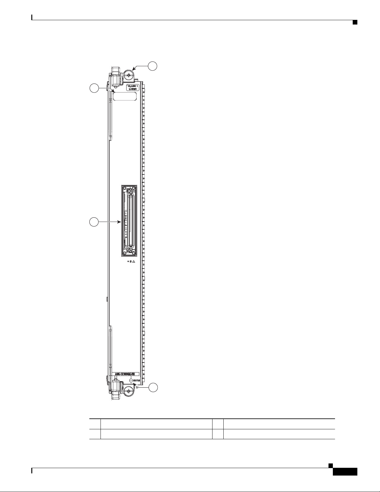
Chapter 2 Functional Description
1
4
2
3
Ethernet Line Cards
Figure 2-33 1-Port 100-Gigabit Ethernet (1x100GE) Line Card Front Panel
1 Ejector lever (one of two) 3 100-GE Port
2 Captive installation screw (one of two) 4 Line Card Status LED
Cisco ASR 9000 Series Aggregation Services Router Overview and Reference Guide
OL-17501-09
2-43
Page 92

Modular Line Cards
330785
Modular Line Cards
The modular line card is available in two network processing unit (80-gb throughput) and in four
network processing unit (160-gb throughput) versions. Each version is available in either a Service Edge
Optimized (-SE) or Packet Transport Optimized (-TR) version. Both versions are functionally
equivalent, but vary in configuration scale and buffer capacity.
Figure 2-34 shows a modular line card with a 20-port Gigabit Ethernet modular port adapter (MPA)
installed in the lower bay. As shown in Figure 2-34, Bay 0 is the “upper” or “left” bay, and Bay 1 is the
“lower” or “right” bay.
Figure 2-34 Modular Line Card
Chapter 2 Functional Description
The MPA has Active/Link (A/L) LEDs visible on the front panel. Each A/L LED shows the status of both
the port and the link. A green A/L LED means the state is on, the port is enabled, and the link is up. An
amber A/L LED means the state is on, the port is enabled, and the link is down. An A/L LED that is off
means the state is off, the port is not enabled, and the link is down.
The modular line card provides two bays that support the following MPAs:
• 20-port GE MPA
• 8-port 10-GE MPA
• 4-port 10-GE MPA
• 2-port 10-GE MPA
• 2-port 40-GE MPA
• 1-port 40-GE MPA
20-port Gigabit Ethernet Modular Port Adapter
The 20-port Gigabit Ethernet MPA provides 10 double-stacked SFP (20 total) cages that support either
fiber-optic or copper Gigabit Ethernet transceivers. It also supports copper SFP modules with
10/100-1000 Mbps speed.
Each SFP cage on the Gigabit Ethernet MPA has an adjacent A/L LED visible on the front panel. The
A/L LED indicates the status of the associated SFP port.
Figure 2-35 shows an example of the 20-port Gigabit Ethernet MPA.
2-44
Cisco ASR 9000 Series Aggregation Services Router Overview and Reference Guide
OL-17501-09
Page 93

Chapter 2 Functional Description
Figure 2-35 20-Port Gigabit Ethernet MPA
Modular Line Cards
330784
8-port 10-Gigabit Ethernet Modular Port Adapter
The 8-Port 10-Gigabit Ethernet modular port adapter provides eight cages for SFP+ Ethernet optical
interface modules that operate at a rate of 10-Gbps.
The 8-Port 10-Gigabit Ethernet modular port adapter has the following guidelines and limitations:
• The 8-Port 10-Gigabit Ethernet modular port adapter is supported on the 160-Gigabyte Modular
Line Card only (A9K-MOD160-TR and A9K-MOD160-SE).
• The 8-Port 10-Gigabit Ethernet modular port adapter is not supported on the 80-Gigabyte Modular
Line Card (A9K-MOD80-TR and A9K-MOD80-SE).
• The 8-Port 10-Gigabit Ethernet modular port adapter is not supported on the Cisco ASR 9001
Router.
Each SFP+ cage on the 8-Port 10-Gigabit Ethernet modular port adapter has an adjacent A/L
(Active/Link) LED visible on the front panel. The A/L (Active/Link) LED indicates the status of the
associated SFP+ port.
Figure 2-36 shows an example of the 8-Port 10-Gigabit Ethernet MPA.
OL-17501-09
Cisco ASR 9000 Series Aggregation Services Router Overview and Reference Guide
2-45
Page 94

Modular Line Cards
Figure 2-36 8-Port 10-Gigabit Ethernet MPA
A9K-MP A-8X 10GE
A/L
A/L
A/L
0
A/L
1
2
A/L
3
A/L
A/L
4
A/L
5
6
7
STATUS
Chapter 2 Functional Description
303443
A9K-MP A-8X 10GE
4-Port 10-Gigabit Ethernet Modular Port Adapter
The 4-Port 10-Gigabit Ethernet MPA provides four cages for XFP Ethernet optical interface modules
that operate at a rate of 10-Gbps. The four XFP modules can be 10-Gigabit Ethernet multimode
connections.
Each XFP cage on the 4-Port 10-Gigabit Ethernet MPA has an adjacent A/L LED visible on the front
panel. The A/L LED indicates the status of the associated XFP port.
Figure 2-37 shows an example of the 4-Port 10-Gigabit Ethernet MPA.
2-46
Cisco ASR 9000 Series Aggregation Services Router Overview and Reference Guide
OL-17501-09
Page 95

Chapter 2 Functional Description
Figure 2-37 4-Port 10-Gigabit Ethernet MPA
A9K-MPA-2X10GE
Modular Line Cards
0
STATUS
A9K-MPA-2X10GE
2-port 10-Gigabit Ethernet Modular Port Adapter
The 2-Port10-Gigabit Ethernet MPA provides two cages for XFP Ethernet optical interface modules that
operate at a rate of 10-Gbps. The two XFP modules can be 10-Gigabit Ethernet multimode connections.
Each XFP cage on the 2-Port10-Gigabit Ethernet MPA has an adjacent A/L LED visible on the front
panel. The A/L LED indicates the status of the associated XFP port.
Figure 2-38 shows an example of the 2-port10-Gigabit Ethernet MPA.
333949
OL-17501-09
Cisco ASR 9000 Series Aggregation Services Router Overview and Reference Guide
2-47
Page 96

Modular Line Cards
Chapter 2 Functional Description
Figure 2-38 2-Port 10-Gigabit Ethernet MPA
A9K-MPA-2X10GE
0
STATUS
A9K-MPA-2X10GE
2-Port 40-Gigabit Ethernet Modular Port Adapter
The 2-Port 40-Gigabit Ethernet MPA provides two cages for QSFP+ Ethernet optical interface modules
that operate at a rate of 40 Gbps. The two QSFP+ modules can be 40-Gigabit Ethernet multimode or
single mode connections.
Each QSFP+ cage on the 2-Port 40-Gigabit Ethernet MPA has an adjacent A/L LED visible on the front
panel. The A/L LED indicates the status of the associated QSFP+ port.
Figure 2-39 shows an example of the 2-Port 40-Gigabit Ethernet MPA.
330782
2-48
Cisco ASR 9000 Series Aggregation Services Router Overview and Reference Guide
OL-17501-09
Page 97

Chapter 2 Functional Description
330782
STATUS
A9K-MPA-2X10GE
A9K-MPA-2X10GE
0
Figure 2-39 2-Port 40-Gigabit Ethernet MPA
Modular Line Cards
1-Port 40-Gigabit Ethernet Modular Port Adapter
The 1-Port 40-Gigabit Ethernet modular port adapter provides a cage for a QSFP+ Ethernet optical
interface module that operates at a rate of 40-Gbps. The QSFP+ module can support either a 40-Gigabit
Ethernet multimode connection or a 40-Gigabit Ethernet single mode connection.
Each QSFP cage on the 1-Port 40 Gigabit Ethernet modular port adapter has an adjacent A/L
(Active/Link) LED visible on the front panel. The A/L LED indicates the status of the associated QSFP+
port.
Refer to Figure 2-40 below for an example of the 1-Port 40-Gigabit Ethernet modular port adapter.
OL-17501-09
Cisco ASR 9000 Series Aggregation Services Router Overview and Reference Guide
2-49
Page 98

Power System Functional Description
Figure 2-40 1-Port 40-Gigabit Ethernet Modular Port Adapter
Chapter 2 Functional Description
333939
Power System Functional Description
The Cisco ASR 9000 Series Routers can be powered with an AC or DC source power. The power system
is based on a distributed power architecture centered around a –54 VDC printed circuit power bus on the
system backplane.
The –54 VDC system backplane power bus can be sourced from one of two options:
• AC systems—AC/DC bulk power supply tray connected to the user’s 200 to 240 V +/- 10 percent
(180 to 264 VAC) source.
• DC systems—DC/DC bulk power supply tray connected to the user’s Central Office DC battery
source (–54 VDC nominal).
The system backplane distributes DC power from the backplane to each card and the fan trays. Each card
has on-board DC-DC converters to convert the –54 VDC from the distribution bus voltage to the voltages
required by each particular card.
The power system has single-point grounding on the –54 VDC Return, that is, the –54 VDC Return is
grounded to the chassis ground on the backplane only. In the Cisco ASR 9922 Router and Cisco ASR
9912 Router, the internal –54 VDC power distribution is isolated from the central office by the
transformers inside the power modules. It has single-point grounding on the –54 VDC Return internal
distribution bus.
All field replaceable modules of the power system are designed for Online Insertion and Removal (OIR),
so they can be installed or removed without causing interruption to system operation.
2-50
Cisco ASR 9000 Series Aggregation Services Router Overview and Reference Guide
OL-17501-09
Page 99

Chapter 2 Functional Description
AC Power Shelf-0
w/AC/DC Power Supply Modules
Powe r Distribution
Backplane
Fan Tray 0
AC/DC
Pwr Sply
Module-
PM0
3KW
EMI
Filter
–54V
–54V
–54V
–54V
–54V RTN
–54V
–54V
AC1-1
220V
20A 1O
243303
Soft-Start
Circuit,
EMI Filter
Fan
Controller
and
Cooling
Fans
AC/DC
Pwr Sply
Module-
PM1
3KW
EMI
Filter
AC1-2
220V
20A 1O
AC/DC
Pwr Sply
Module-
PM2
3KW
EMI
Filter
AC1-3
220V
20A 1O
AC Power Shelf-1
w/AC/DC Power Supply Modules
AC/DC
Pwr Sply
Module-
PM3
3KW
EMI
Filter
–54V
AC2-1
220V
20A 1O
AC/DC
Pwr Sply
Module-
PM4
3KW
EMI
Filter
AC2-2
220V
20A 1O
AC/DC
Pwr Sply
Module-
PM5
3KW
EMI
Filter
AC2-3
220V
20A 1O
Line Card (x8)
Soft-Start
Circuit,
EMI Filter
Narrow
Range,
Fixed
Ratio
(5:1)
10.8V
Converter
Point of
Load
(POL)
Converters
RSP Card (x2)
Soft-Start
Circuit,
EMI Filter
Narrow
Range,
Fixed
Ratio
(5:1)
10.8V
Converter
Point of
Load
(POL)
Converters
Fan Tray 1
Soft-Start
Circuit,
EMI Filter
Fan
Controller
and
Cooling
Fans
–54V
–54V
–54V
–10.8V
–10.8V
Power System Functional Description
Figure 2-41 and Figure 2-42 show block diagrams of the ASR 9010 Router AC power system with
version 1 and version 2 power systems. Figure 2-43 and Figure 2-44 show block diagrams of the
ASR 9010 Router DC power system with version 1 and version 2 power systems.
Note The Cisco ASR 9000 Series Routers have two available DC version 1 power modules, a 2100 W module
and a 1500 W module. Both types of power modules can be used in a single chassis. The
ASR 9000 Series Routers have one available DC version 2 power module (2100 W).
Figure 2-41 Cisco ASR 9010 Router AC Power System Block Diagram—Version 1 Power System
OL-17501-09
Cisco ASR 9000 Series Aggregation Services Router Overview and Reference Guide
2-51
Page 100

Chapter 2 Functional Description
Power System Functional Description
Figure 2-42 Cisco ASR 9010 Router AC Power System Block Diagram—Version 2 Power System
AC1-1
220V
20A 1O
AC1-2
220V
20A 1O
AC1-3
220V
20A 1O
AC1-4
220V
20A 1O
AC2-1
220V
20A 1O
AC2-2
220V
20A 1O
AC Power Shelf-0
w/AC/DC Power Supply Modules
AC/DC
EMI
Filter
EMI
Filter
EMI
Filter
EMI
Filter
w/AC/DC Power Supply Modules
EMI
Filter
EMI
Filter
Pwr Sply
Module-
PM0
3 KW
AC/DC
Pwr Sply
Module-
PM1
3 KW
AC/DC
Pwr Sply
Module-
PM2
3 KW
AC/DC
Pwr Sply
Module-
PM3
3 KW
AC Power Shelf-1
AC/DC
Pwr Sply
Module-
PM4
3 KW
AC/DC
Pwr Sply
Module-
PM5
3 KW
–54V
–54V
Power Distribution
Backplane
–54V RTN
–54V
–54V
–54V
Soft-Start
Circuit,
EMI Filter
Soft-Start
Circuit,
EMI Filter
Soft-Start
Circuit,
EMI Filter
Fan Tray 0
Fan
Controller
–54V
–54V –10.8V
–54V –10.8V
and
Cooling
Fans
Line Card (x8)
Narrow
Range,
Fixed
Ratio
(5:1)
10.8V
Converter
RSP Card (x2)
Narrow
Range,
Fixed
Ratio
(5:1)
10.8V
Converter
Point of
Load
(POL)
Converters
Point of
Load
(POL)
Converters
AC2-3
220V
20A 1O
AC2-4
220V
20A 1O
2-52
AC/DC
EMI
Filter
EMI
Filter
Cisco ASR 9000 Series Aggregation Services Router Overview and Reference Guide
Pwr Sply
Module-
PM6
3 KW
AC/DC
Pwr Sply
Module-
PM7
3 KW
–54V
Soft-Start
Circuit,
EMI Filter
–54V
Fan Tray 1
Fan
Controller
and
Cooling
Fans
24402
OL-17501-09
 Loading...