

Page 1

Hardware Installation Guide for the Cisco 900 Series Integrated
Services Router
Last Modified: 2019-01-11
Americas Headquarters
Cisco Systems, Inc.
170 West Tasman Drive
San Jose, CA 95134-1706
USA
http://www.cisco.com
Tel: 408 526-4000
800 553-NETS (6387)
Fax: 408 527-0883
Page 2

©
2019–2019 Cisco Systems, Inc. All rights reserved.
Page 3

CONTENTS
CHAPTER 1
CHAPTER 2
Overview of Cisco 900 Series Integrated Services Routers 1
About Cisco 900 Series Integrated Service Routers 1
Chassis Views 2
LED Indicators 5
Power Supply 6
Specifications of Cisco 900 Series Integrated Services Routers 7
Periodic Inspection and Cleaning 7
Prepare for Router Installation 9
Safety Recommendations 9
Safety With Electricity 9
Prevent Electrostatic Discharge Damage 10
General Site Requirements 10
Site Selection Guidelines 11
Rack Requirements 11
Router Environmental Requirements 12
Power Guidelines and Requirements 12
Network Cabling Specifications 13
Console Port Connections 13
EIA/TIA-232 13
Console Port Considerations 14
Preparing for Network Connections 14
Ethernet Connections 14
Required Tools and Equipment for Installation 14
CHAPTER 3
Install and Connect the Router 17
Hardware Installation Guide for the Cisco 900 Series Integrated Services Router
iii
Page 4

Contents
Unpack the Router 17
Set up Router on Desktop, Rack, Shelf, or Wall 17
Rack Mount 18
Attach the Brackets to the Router 18
Mount the Router 19
Wall Mount 21
Mount the Router on Desk or Shelf 24
Mount the Router under a Desk or a Shelf 25
Chassis Grounding 27
Connect Power Cable 28
Connect the Router to a Console 29
Connect to the Serial Port with Microsoft Windows 30
Connect to the Console Port with Mac OS X 30
CHAPTER 4
Connect to the Console Port with Linux 31
Connect WAN and LAN Interfaces 31
Ports and Cabling 32
Connection Procedures and Precautions 32
Configure the Router at Startup 32
ROM Monitor Overview and Basic Procedures 33
ROM Monitor Overview 33
Hardware Installation Guide for the Cisco 900 Series Integrated Services Router
iv
Page 5
CHAPTER 1
Overview of Cisco 900 Series Integrated Services
Routers
Cisco 900 Series Integrated Services Routers (ISRs) with Cisco IOS Software are high-performance devices
that are easy to deploy and manage. The routers combine Internet access, comprehensive security, and wireless
services (LTE Advanced 3.0, Wireless WAN and Wireless LAN).
• About Cisco 900 Series Integrated Service Routers, on page 1
• Periodic Inspection and Cleaning, on page 7
About Cisco 900 Series Integrated Service Routers
The Cisco 900 series Integrated Services Routers are the SOHO routers that offer unmatched throughput
levels. They are available in fixed form factors. The Cisco 900 series is best suited for small and midsize
businesses, enterprise branches and as customer premises equipment in managed services environments.
Table 1: Base models of the Cisco 900 series ISR
DSLConsole PortsWAN PortsSwitch PortsModel
None124C921-4P
None124C921J-4P
1114C926-4P
1114C927-4P
1114C927-4PM
None124C931-4P
For more information on the features and specifications of Cisco 900 Series Integrated Services Routers
(ISRs), refer to the Cisco 900 Series Integrated Services Routers datasheet.
Hardware Installation Guide for the Cisco 900 Series Integrated Services Router
1
Page 6

Chassis Views
Chassis Views
Overview of Cisco 900 Series Integrated Services Routers
This section contains front and back panel views of the Cisco 900 Series ISR-showing locations of the power
and signal interfaces, interface slots, status indicators, and chassis identification labels.
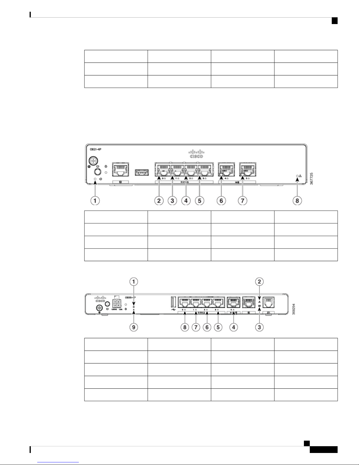
Figure 1: Cisco C921-4P- I/O View
Power button2#6-32 Ground screw1
Figure 2: Cisco C921J-4P - I/O View
Console Port4Reset button3
GE LAN port6USB2.0 port5
GE LAN port8GE LAN port7
GE WAN port10GE LAN port9
VPN LED12GE WAN port11
Power button2#6-32 Ground screw1
Hardware Installation Guide for the Cisco 900 Series Integrated Services Router
2
Reset button412VDC input3
VPN LED6System LED5
GE LAN port8USB2.0 port7
GE LAN port10GE LAN port9
Page 7

Overview of Cisco 900 Series Integrated Services Routers
Figure 3: Cisco C926-4P- I/O View
Chassis Views
GE WAN port12GE LAN port11
Console port14GE WAN port13
Kensington Lock15
Power button2#6-32 Ground screw1
Figure 4: Cisco C927-4P - I/O View
Reset button412VDC input3
USB2.0 port6System LED5
DSL port8xDSL CD LED7
Console port10xDSL DATA LED9
GE LAN port12GE WAN port11
GE LAN port14GE LAN port13
VPN LED16GE LAN port15
Power button2#6-32 Ground screw1
Reset button412VDC input3
USB2.0 port6System LED5
DSL port8xDSL CD LED7
Console port10xDSL DATA LED9
Hardware Installation Guide for the Cisco 900 Series Integrated Services Router
3
Page 8

Chassis Views
Overview of Cisco 900 Series Integrated Services Routers
GE LAN port12GE WAN port11
GE LAN port14GE LAN port13
VPN LED16GE LAN port15
Figure 5: Cisco C927-4PM - I/O View
Power button2#6-32 Ground screw1
Figure 6: Cisco C931-4P - I/O View
Reset button412VDC input3
USB2.0 port6System LED5
DSL port8xDSL CD LED7
Console port10xDSL DATA LED9
GE LAN port12GE WAN port11
GE LAN port14GE LAN port13
VPN LED16GE LAN port15
Hardware Installation Guide for the Cisco 900 Series Integrated Services Router
4
Power button2#6-32 Ground screw1
Console port4Reset button3
GE LAN port6USB2.0 port5
Page 9
Overview of Cisco 900 Series Integrated Services Routers
LED Indicators
The following figures and table summarize the LED indicators that are located in the bezel or chassis of the
900 series.
Figure 7: LED Indicators on Ethernet SKUs- I/O Side
LED Indicators
GE LAN port8GE LAN port7
GE WAN port10GE LAN port9
VPN LED12GE WAN port11
Figure 8: LED Indicators on DSL SKUs- I/O Side
LAN LED2Power LED1
LAN LED4LAN LED3
WAN LED6LAN LED5
VPN LED8WAN LED7
xDSL CD LED2System LED1
WAN LED4xDSL DATA LED3
LAN LED6LAN LED5
LAN LED8LAN LED7
VPN LED9
Hardware Installation Guide for the Cisco 900 Series Integrated Services Router
5
Page 10
Power Supply
Overview of Cisco 900 Series Integrated Services Routers
The following table summarizes the LED indicators that are located in the chassis of the Cisco ISR 900 series
routers.
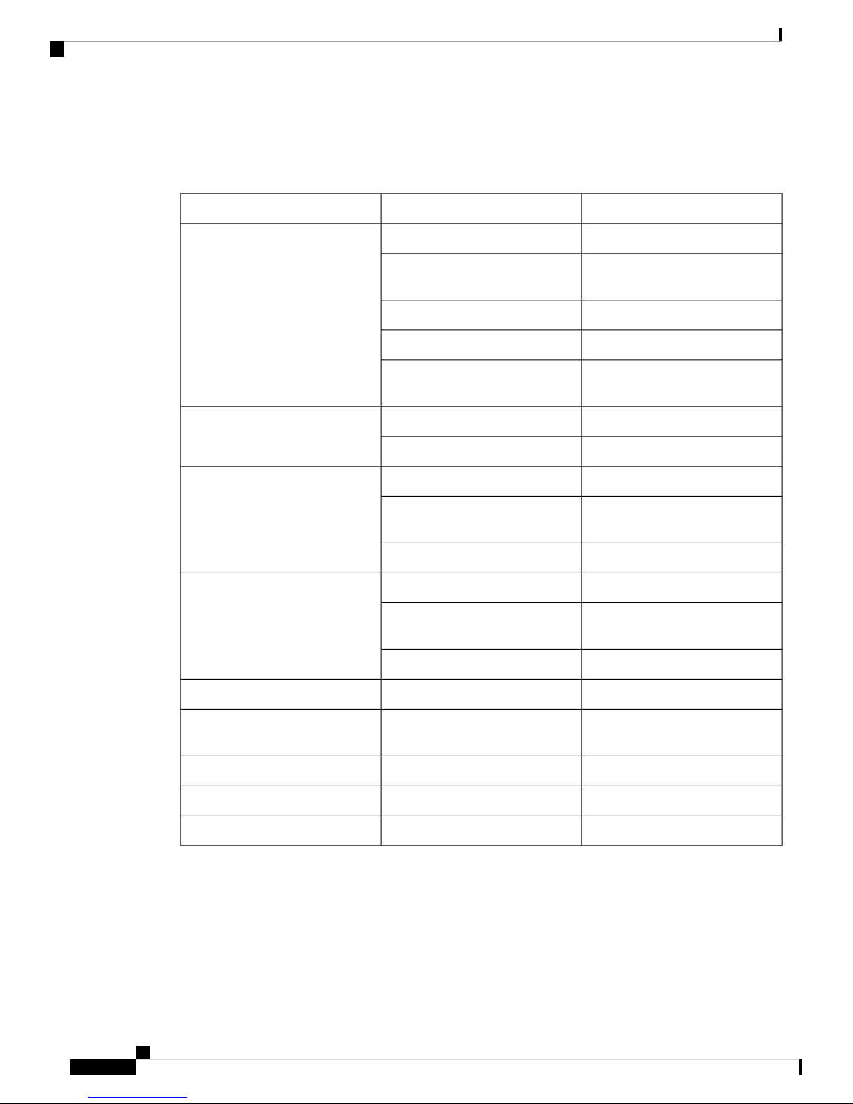
Table 2: LED Indicators for Cisco ISR 900 Series Routers
DescriptionLED ColorPort
System is offOFFSYS
Blink
Amber(blink)
GreenVPN OK
Green(Solid)LAN
Green (Blinking)
Green(Solid)WAN
Green (Blinking)
Boot up phase or in ROM Monitor
mode
Normal operationSteady on
Thermal tripAmber(steady)
ROMMON code signing
verification failure
At least one VPN session is active
VPN not connectedOFF
LAN connection is established.
Data transmission is happening on
the link.
LAN is not connectedOFF
WAN link is established
Data transmission is happening on
the link.
WAN link is not connected.OFF
Power Supply
The product power specifications for external power supply units are as follows:
• AC input voltage: Universal 100 to 240 VAC
• Frequency: 50 to 60 Hz
Hardware Installation Guide for the Cisco 900 Series Integrated Services Router
6
OFFDSL CD
Green(Blinking)
Shut
Training, or no shut and cable
disconnected.
TrainedGreen (solid)
ShutOFFDSL Data
TX/RX DataGreen(Blinking)
Page 11

Overview of Cisco 900 Series Integrated Services Routers
Specifications of Cisco 900 Series Integrated Services Routers
• Maximum output power: 18W or 30W depending on the SKU
• Output voltage: +12VDC for system power
Specifications of Cisco 900 Series Integrated Services Routers
For specifications on the Cisco 900 Series ISRs, refer to the Cisco 900 series Specifications document.
Periodic Inspection and Cleaning
We recommend to periodically inspect and clean the external surface of the router to minimize the negative
impact from environmental dust or debris. The frequency of inspection and cleaning is dependent upon the
severity of the environmental conditions, but we recommend a minimum once in every six months. Cleaning
involves vacuuming router air intake and exhaust vents.
Note
Sites with ambient temperatures consistently above 25°C and with potentially high levels of dust or debris
might require periodic preventative maintenance cleaning.
Hardware Installation Guide for the Cisco 900 Series Integrated Services Router
7
Page 12

Periodic Inspection and Cleaning
Overview of Cisco 900 Series Integrated Services Routers
Hardware Installation Guide for the Cisco 900 Series Integrated Services Router
8
Page 13

Prepare for Router Installation
Before you install the Cisco 900 Series Integrated Services Routers, you must prepare your site for the
installation. This chapter provides pre-installation information, such as recommendations and requirements
that should be considered before installing your router.
See the following sections to prepare for installation:
• Safety Recommendations, on page 9
• General Site Requirements, on page 10
• Rack Requirements, on page 11
• Router Environmental Requirements, on page 12
• Power Guidelines and Requirements, on page 12
• Network Cabling Specifications, on page 13
• Required Tools and Equipment for Installation , on page 14
Safety Recommendations
CHAPTER 2
Warning
IMPORTANT SAFETY INSTRUCTIONS
This warning symbol means danger. You are in a situation that could cause bodily injury. Before you work
on any equipment, be aware of the hazards involved with electrical circuitry and be familiar with standard
practices for preventing accidents. Use the statement number provided at the end of each warning to locate
its translation in the translated safety warnings that accompanied this device. Statement 1071
SAVE THESE INSTRUCTIONS
Safety With Electricity
Warning
No user-serviceable parts inside. Do not open. Statement 1073
Hardware Installation Guide for the Cisco 900 Series Integrated Services Router
9
Page 14

Prevent Electrostatic Discharge Damage
Prepare for Router Installation
Warning
Warning
Only trained and qualified personnel should be allowed to install, replace, or service this equipment. Statement
1030.
Ultimate disposal of this product should be handled according to all national laws and regulations. Statement
1040.
Prevent Electrostatic Discharge Damage
Electrostatic discharge (ESD) can damage equipment and impair electrical circuitry. It can occur if electronic
printed circuit cards are improperly handled and can cause complete or intermittent failures. Always follow
ESD prevention procedures when removing and replacing modules:
• Ensure that the router chassis is electrically connected to ground.
• Wear an ESD-preventive wrist strap, ensuring that it makes good skin contact. Connect the clip to an
unpainted surface of the chassis frame to channel unwanted ESD voltages safely to ground. To guard
against ESD damage and shocks, the wrist strap and cord must operate effectively.
• If no wrist strap is available, ground yourself by touching a metal part of the chassis.
Caution
For the safety of your equipment, periodically check the resistance value of the anti-static strap. It should be
between 1 and 10 megohms (Mohm).
General Site Requirements
Warning
Warning
Warning
Warning
10
Installation of the equipment must comply with local and national electrical codes. Statement 1074
Connect the Chassis to Earth Ground—To reduce the risk of electric shock, the chassis of this equipment
needs to be connected to permanent earth ground during normal use. Statement 445
This product relies on the building’s installation for short-circuit (overcurrent) protection. Ensure that the
protective device is rated not greater than: 20A. Statement 1005
Take care when connecting units to the supply circuit so that wiring is not overloaded. Statement 1018
Hardware Installation Guide for the Cisco 900 Series Integrated Services Router
Page 15

Prepare for Router Installation
Site Selection Guidelines
Warning
Note
Note
To prevent the system from overheating, do not operate the devices in an area that exceeds the maximum
recommended ambient temperature. Statement 1047.
Table 3: Ambient Temperature of SKUs
Ambient TemperatureSKU
Internal PSU
C931-4P
External PSU
C926-4P
C927-4P
C927-4PM
For altitudes above sea-level, de-rate the ambient operating temperature 1°C per 1000-feet of elevation.
Cisco 900 series routers are fanless, normally run warm to the touch, and require adequate clearances for
proper heat dissipation and ventilation.
50 °CC921-4P
45 °CC921J-4P
Site Selection Guidelines
The Cisco 900 Series ISRs require specific environmental operating conditions. Temperature, humidity,
altitude, and vibration can affect the performance and reliability of the router. The following sections provide
specific information to help you plan for the proper operating environment.
The Cisco 900 Series ISRs are designed to meet the industry EMC, safety, and environmental standards
described in the Regulatory Compliance and Safety Information for the Cisco 900 Series ISR document.
Rack Requirements
Routers with internal Power Supplies can be mounted in a 19-inch rack using rack-mount brackets (optional
kit). Routers with external Power Supplies require a customer-provided tray for mounting in a rack.
The following information helps you plan your equipment rack configuration:
• Allow clearance around the rack for maintenance.
• Allow at least one rack unit of vertical space between routers; more clearance is required when stacking
multiple Cisco 900 Series ISRs. Provide adequate heat removal mechanism so that heat does not build
up in the rack and the air surrounding the router is well within the specified operating ambient temperature
condition.
Hardware Installation Guide for the Cisco 900 Series Integrated Services Router
11
Page 16

Router Environmental Requirements
Note
More spacing may be required depending on the installation environment.
• Enclosed racks must have adequate ventilation. Ensure that the rack is not congested, because each router
generates heat. An enclosed rack should have louvered sides and a fan to provide cooling air. Heat
generated by equipment near the bottom of the rack can be drawn upward into the intake ports of the
equipment above it.
Router Environmental Requirements
Cisco 900 Series ISRs can be installed on a desk or a shelf, under a desk or a shelf, on a wall, and in a rack,
depending on the SKU. The location of your router and the layout of your equipment rack or wiring room are
extremely important considerations for proper operation. Equipment installed too close together, inadequate
ventilation, and inaccessible panels can cause malfunctions and shutdowns, and can make maintenance difficult.
Plan your installation site for accessing both front and rear panels of the router.
Prepare for Router Installation
When planning your site layout and equipment locations, refer to the General Site Requirements , section. If
you are currently experiencing shutdowns or an unusually high number of errors with your existing equipment,
these precautions and recommendations may help you isolate the cause of failure and prevent future problems.
• Ensure that the room where your router operates has adequate air circulation. Electrical equipment
generates heat. Without adequate air circulation, ambient air temperature may not cool equipment to
acceptable operating temperatures.
• Always follow ESD-prevention procedures described in the Preventing Electrostatic Discharge Damage
to avoid damage to equipment. Damage from static discharge can cause immediate or intermittent
equipment failure.
• When equipment installed in a rack (particularly in an enclosed rack) fails, try operating the equipment
by itself, if possible. Power off other equipment in the rack (and in adjacent racks) to allow the router
under test a maximum of cooling air and clean power.
Power Guidelines and Requirements
Cisco 900 series routers come with the following power options:
• Routers with internal AC power supply
• Routers with external AC power supply
Table 4: SKUs with Internal and External Power Supplies
Internal
Hardware Installation Guide for the Cisco 900 Series Integrated Services Router
12
SKUPower Supply
C921-4P
C931-4P
Page 17

Prepare for Router Installation
Network Cabling Specifications
SKUPower Supply
External
Note
Do not hang the Power Supply Unit (PSU) from the power socket. Place it on a surface.
Note
Check the power at your site to ensure that you are receiving power that is free of spikes and noise. Install a
power conditioner if necessary
Table 5: Power Requirements for Cisco 900 Series ISRs
Supply
(PWR-18W-AC(=))
C921J-4P
C926-4P
C927-4P
C927-4PM
Output RatedInput RatedSKU modelsPower Source
12VDC, 1.5A100-240V, 0.5A• C921J-4P18W AC External Power
30W AC External Power
Supply
(PWR-30W-AC(=))
• C927-4P
• C927-4PM
Network Cabling Specifications
The following sections describe the cables and thee specifications required to install Cisco 900 Series ISRs:
Console Port Connections
The Cisco 900 ISR has both EIA/TIA-232 asynchronous (RJ-45) and USB2.0 compliant serial console ports.
The console ports do not have any hardware flow control. Shielded USB cables with properly terminated
shields are recommended.
EIA/TIA-232
Depending on the cable and the adapter used, this port appears as a DTE or DCE device at the end of the
cable.
12VDC, 2.5A100-240V, 1.0A• C926-4P
Hardware Installation Guide for the Cisco 900 Series Integrated Services Router
13
Page 18

Console Port Considerations
The default parameters for the console port are 9600 baud, 8 data bits, 1 stop bit, and no parity. The console
port does not support hardware flow control. For detailed information about installing a console terminal, see
the Connecting to a Console Terminal or Modem section.
For cable and port pinouts, see the Cisco Modular Access Router Cable Specifications document available
on cisco.com.
Console Port Considerations
The router includes an asynchronous serial console port. The console ports provide access to the router using
a console terminal connected to the console port. This section discusses important cabling information to
consider before connecting the router to a console terminal or modem.
Console terminals send data at speeds slower than modems do; therefore, the console port is ideally suited
for use with console terminals.
Preparing for Network Connections
When setting up your router, consider distance limitations and potential electromagnetic interference (EMI)
as defined by the applicable local and international regulations.
Prepare for Router Installation
Network connection considerations are provided for:
See the following online document for more information about network connections and interfaces:
• Cisco Modular Access Router Cable Specifications
Ethernet Connections
The IEEE has established Ethernet as standard IEEE 802.3. The routers support the following Ethernet
implementations:
• 1000BASE-T—1000 Mb/s full-duplex transmission over a Category 5 or better unshielded twisted-pair
(UTP) cable. Supports the Ethernet maximum length of 328 feet (100 meters).
• 100BASE-T—100 Mb/s full-duplex transmission over a Category 5 or better unshielded twisted-pair
(UTP) cable. Supports the Ethernet maximum length of 328 feet (100 meters).
• 10BASE-T—10 Mb/s full-duplex transmission over a Category 5 or better unshielded twisted-pair (UTP)
cable. Supports the Ethernet maximum length of 328 feet (100 meters).
See the Cisco Modular Access Router Cable Specifications document on Cisco.com for information about
Ethernet cables, connectors, and pinouts.
Required Tools and Equipment for Installation
You need the following tools and equipment to install and upgrade the router and its components:
• ESD-preventive cord and wrist strap
• Number 2 Phillips screwdriver
• Phillips screwdrivers: small, 3/16-in. (4 to 5 mm) and medium, 1/4-in. (6 to 7 mm)
• Screws that fit your rack
Hardware Installation Guide for the Cisco 900 Series Integrated Services Router
14
Page 19

Prepare for Router Installation
Required Tools and Equipment for Installation
• Wire crimper
• Wire for connecting the chassis to an earth ground:
• AWG 14 (2 mm2) or larger wire for chassis grounding
• For grounding, an appropriate user-supplied ring terminal sized appropriately for a #6-32 screw.
Hardware Installation Guide for the Cisco 900 Series Integrated Services Router
15
Page 20

Required Tools and Equipment for Installation
Prepare for Router Installation
Hardware Installation Guide for the Cisco 900 Series Integrated Services Router
16
Page 21

CHAPTER 3
Install and Connect the Router
This chapter describes how to install and connect Cisco 900 Series Integrated Services Router (ISR) to LAN
and WAN networks.
Warning
Read the installation instructions before using, installing or connecting the system to the power source.
Statement 1004
Installing the Cisco 900 Series ISRs involves these tasks:
• Unpack the Router, on page 17
• Set up Router on Desktop, Rack, Shelf, or Wall, on page 17
• Connect Power Cable, on page 28
• Connect the Router to a Console, on page 29
• Connect WAN and LAN Interfaces, on page 31
• Configure the Router at Startup, on page 32
Unpack the Router
Unpack the router only when you are ready to install it. If the installation site is not ready, to prevent accidental
damage, keep the chassis in its shipping container until you are ready to install.
The router, accessory kit, publications, and any optional equipment you order may be shipped in more than
one container. When you unpack the containers, check the packing list to ensure that you have received all
listed items.
Set up Router on Desktop, Rack, Shelf, or Wall
After unpacking, based on your requirements, you can set up a Cisco 900 Series Integrated Services Routers
(ISRs) on a desk or a shelf, under a desk or a shelf, in a rack, or on a wall.
Depending on the model, the available options for mounting a Cisco 900 ISR are:
Hardware Installation Guide for the Cisco 900 Series Integrated Services Router
17
Page 22

Rack Mount
Install and Connect the Router
Table 6: Models and Mounting Options
Kit RequiredMounting OptionsSKU
Rack Mount
Note
Internal PSU
C931-4P
None: Mounting feet are part of the router.On a desk or shelf.C921-4P
Yes: You must order Under-desk kit.Under a desk or
shelf.
Yes: You must order rack-mount-bracket kit.In a rack
External PSU
C921J-4P
C926-4P
C927-4P
None: Mounting feet are part of the router.On a desk or shelf.
None: You must provide your own tray.In a rack.
None: You must provide wall-mount hardware.On a wall.
C927-4PM
If you choose to setup the router on a desktop, you can place the router on a desktop, bench top, or shelf.
Installing the router in a rack requires an optional bracket kit that is not included with the router. You can
order these kits from your Cisco representative.
Cisco 900 Series Routers are fanless. When stacking multiple Cisco 900 ISRs, ensure that there is ample
surrounding space. Ample space, in turn, ensures more heat removal to enable the surrounding air temperature
to stay within the specified operating conditions. A minimum of 1RU space is required above and below the
router in the rack for proper ventilation. Refer Figure 13: Mounting the Cisco ISR 900 Series Router in a
Rack, on page 20
Attach the Brackets to the Router
This procedure describes how to attach the brackets on the router chassis:
Attach a 19-inch bracket to one side of the router using flat-head screw (Refer Figure 10: Flat-head Machine Screws, on
page 19). Follow the same steps to attach the second bracket to the opposite side.
Figure 9: Attaching Brackets to the Cisco ISR 900 Series Router
Hardware Installation Guide for the Cisco 900 Series Integrated Services Router
18
Page 23

Install and Connect the Router
Figure 10: Flat-head Machine Screws
Figure 11: Router with Bracket Attached to Back Panel
Mount the Router
Figure 12: Router with Bracket Attached to Front Panel
Mount the Router
Warning
Before mounting the router on to the rack, refer to the following safety warning statements:
To prevent airflow restriction, allow clearance around the ventilation openings to be at least: 1.75 in. (4.4
cm). Statement 1076.
Hardware Installation Guide for the Cisco 900 Series Integrated Services Router
19
Page 24

Mount the Router
Install and Connect the Router
Warning
To prevent bodily injury when mounting or servicing this unit in a rack, you must take special precautions to
ensure that the system remains stable. The following guidelines are provided to ensure your safety:
• This unit should be mounted at the bottom of the rack if it is the only unit in the rack.
• When mounting this unit in a partially filled rack, load the rack from the bottom to the top with the
heaviest component at the bottom of the rack.
• If the rack is provided with stabilizing devices, install the stabilizers before mounting or servicing the
unit in the rack. Statement 1006.
After the brackets are attached to the router, insert the router into the rack, and align the bracket in the rack. Use the
machine screws to secure the router in the rack.
Figure 13: Mounting the Cisco ISR 900 Series Router in a Rack
Note
Allow at least one rack unit (1RU) of vertical space between routers. More clearance may be required when
stacking multiple products in the rack that could build up heat in the rack. Ensure that the ambient around the
router is within the ambient temperature specified in Table 3: Ambient Temperature of SKUs, on page 11.
Note
The local ambient (not room ambient) is measured below the router.
Routers with external power supply can be mounted in a tray as shown in figure below.
Hardware Installation Guide for the Cisco 900 Series Integrated Services Router
20
Page 25

Install and Connect the Router
Figure 14: Mounting the Cisco ISR 900 Series Router in a Tray
Wall Mount
Wall Mount
Warning
Note
Note
Cisco 900 ISRs designed for wall-mounting (refer Table 6: Models and Mounting Options, on page 18) have
mounting holes on the bottom of the chassis for securing with screws or anchors to a vertical surface.
Read the wall-mounting instructions carefully before beginning installation. Failure to use the correct hardware
or to follow the correct procedures could result in a hazardous situation to people and damage to the system.
Statement 378
The recommended clearance when a router is horizontally mounted is 1.5 inches on both sides for clearance
and 1.75 inches on top. I/O side clearance is needed as it is required to access the cable connections. Clearance
is not required on the backside (opposite side from I/O face).
For safety reasons, the only supported wall-mount orientation is as shown in step 3 below. The mounting slots
support only this orientation. Marking is provided on the bottom of the router (see step 1) showing the correct
orientation.
Note
When choosing a location for wall mounting the router, consider cable limitations and wall structure.
To mount the router on a wall, follow these steps:
Hardware Installation Guide for the Cisco 900 Series Integrated Services Router
21
Page 26

Install and Connect the Router
Wall Mount
Step 1 Determine the required distance between mounting holes on the router. For Cisco 900 routers, the distance between
mounting holes is 4.15 inches. Figure below shows the wall-mount holes located on the underside of the router.
Figure 15: Router with Wall-mount Holes on the Underside
Step 2 Use a 0.144-inch (3.7 mm) or a #27 drill bit to drill a hole in the wall.
Step 3 Insert the screws, with anchors, into the wall. Leave 1/8 inch (0.32 cm) between the screw head and the wall.
Hardware Installation Guide for the Cisco 900 Series Integrated Services Router
22
Page 27

Install and Connect the Router
Wall Mount
Step 4 Hang the router on the screw without forcibly pushing towards the wall side.
Hardware Installation Guide for the Cisco 900 Series Integrated Services Router
23
Page 28

Mount the Router on Desk or Shelf
Install and Connect the Router
Mount the Router on Desk or Shelf
This procedure describes how to mount router on a desk or a shelf.
Place the router on the desk or shelf. At the bottom of the router there are four rubber feet that protect the router and the
surface it is on.
Figure 16: Mounting the Cisco ISR 900 Series Router on a Desk or a Shelf
Hardware Installation Guide for the Cisco 900 Series Integrated Services Router
24
Page 29

Install and Connect the Router
Figure 17: Bottom of the Router with Rubber Feet
1. Rubber Feet (1 of 4)
Mount the Router under a Desk or a Shelf
Note
Do not stack up routers.
Mount the Router under a Desk or a Shelf
Installing the router under a desk requires an optional bracket kit that is not included with the router. The kit
contains the rack-mount brackets and screws to secure the brackets to the router and the underside of the desk.
You can order these kits from your Cisco representative. This procedure describes how to mount router under
a desk or a shelf .
Step 1 Attach a bracket to one side of the router using the flat-head screws (Refer Figure 19: Flat-head Machine Screws, on page
26). Follow the same steps to attach the second bracket to the opposite side.
Hardware Installation Guide for the Cisco 900 Series Integrated Services Router
25
Page 30

Mount the Router under a Desk or a Shelf
Figure 18: Attaching Brackets to the Router
Figure 19: Flat-head Machine Screws
Install and Connect the Router
Figure 20: Router with Brackets Attached
Step 2 After the brackets are attached, drill a 2 mm hole under the desk and insert the wooden screws provided. Mount the router
under the desk or shelf using the pan-head wood screws (Refer Figure 22: Pan-head Wood Screws, on page 27 ).
Hardware Installation Guide for the Cisco 900 Series Integrated Services Router
26
Page 31

Install and Connect the Router
Figure 21: Mounting the Router under a Desk or Shelf
Figure 22: Pan-head Wood Screws
Chassis Grounding
Chassis Grounding
After you set up the router, connect the chassis to a reliable earth ground; the ground wire must be installed
in accordance with local electrical safety standards. For safety information on grounding the chassis, refer to
the chassis ground connection procedures.
1. For grounding the chassis, use size 14 AWG copper wire and the ground lug. These are not a part of the
accessory kit.
2. Use the UNC 6-32 screw provided with the chassis, which have a length of about 0.25 inches.
To install the ground connection for your router, perform these steps:
1. Strip one end of the ground wire to the length required for the ground lug or terminal.
2. Crimp the ground wire to the ground lug or ring terminal, using a crimp tool of the appropriate size.
3. Attach the ground lug or ring terminal to the chassis as shown in Figure 23: Chassis Ground
Connection-Cisco 900, on page 28. The screw for the ground lug is provided. Tighten the screw; the
recommended torque is 8 to 10 inch-lbf (0.9 to 1.1 N-m).
• For user-provided ring terminal—as required
Hardware Installation Guide for the Cisco 900 Series Integrated Services Router
27
Page 32

Connect Power Cable
Install and Connect the Router
Figure 23: Chassis Ground Connection-Cisco 900
Connect Power Cable
Cisco 900 series routers come with the following power options:
• Routers with internal AC power supply
• Routers with external AC power supply
To power the units that come with an internal power supply, plug in the power cord directly to the power
socket in the front panel. To power the units that come with an external power supply, plug in the DC power
supply to the router's 4-pin power connector in the back panel.
Screw (UNC 6-32)1
Ground Lug2
Hardware Installation Guide for the Cisco 900 Series Integrated Services Router
28
Page 33

Install and Connect the Router
Figure 24: Router with Internal Power Supply
1. Power Cable
Connect the Router to a Console
Figure 25: Router with External Power Supply
1. Power Cable
Connect the Router to a Console
The Cisco 900 Series ISR has an asynchronous serial port. This port provides administrative access to the
router through a console terminal or a PC.
Use the RJ-45 console port on the router to access the Cisco Internet Operating System (IOS) command line
interface (CLI) on the router and perform configuration tasks. A terminal emulation program is required to
establish communication between the router and a PC.
To configure the router through the Cisco IOS CLI, you must establish a connection between the router console
port and either a PC or a terminal.
Hardware Installation Guide for the Cisco 900 Series Integrated Services Router
29
Page 34

Connect to the Serial Port with Microsoft Windows
Use the following cables and adapters to establish a local or remote connection.
Table 7: Local and Remote Connections
Install and Connect the Router
SectionCablePort Type
Cisco 900 ISR: RJ-45 Serial console cableSerial
(RJ-45)
Connecting to the Serial Port with Microsoft
Windows
Connect to the Serial Port with Microsoft Windows
To establish a physical connectivity between the router and a PC, you need to install a Microsoft Windows
USB.
Use the USB Console cable plugged into the USB serial port to establish this connection.ß
1. Connect the end of the console cable with the RJ-45 connector to the light blue console port on the router.
2. Connect the end of the cable with the DB-9 connector (or USB Type-A) to the terminal or PC. If your
terminal or PC has a console port that does not accommodate a DB-9 connector, you must provide an
appropriate adapter for that port.
3. Start a terminal emulator application to communicate with the router. Configure the software with the
following parameters:
• 9600 baud
• 8 data bits
• no parity
• 1 stop bit
• no flow control
Connect to the Console Port with Mac OS X
This procedure describes how to connect a Mac OS X system USB port to the console using the built in OS
X Terminal utility.
Step 1 Use the Finder to go to Applications > Utilities > Terminal.
Step 2 Connect the OS X USB port to the router.
Step 3 Enter the following commands to find the OS X USB port number
Example:
macbook:user$ cd /dev
macbook:user$ ls -ltr /dev/*usb*
crw-rw-rw- 1 root wheel 9, 66 Apr 1 16:46 tty.usbmodem1a21 DT-macbook:dev user$
Step 4 Connect to the USB port with the following command followed by the router USB port speed
Example:
Hardware Installation Guide for the Cisco 900 Series Integrated Services Router
30
Page 35

Install and Connect the Router
macbook:user$ screen /dev/tty.usbmodem1a21 9600
To disconnect the OS X USB console from the Terminal window
Enter Ctrl-a followed by Ctrl-\
Connect to the Console Port with Linux
This procedure shows how to connect a Linux system USB port to the console using the built in Linux Terminal
utility.
Step 1 Open the Linux Terminal window.
Step 2 Connect the Linux USB port to the router.
Step 3 Enter the following commands to find the Linux USB port number
Example:
Connect to the Console Port with Linux
root@usb-suse# cd /dev
root@usb-suse /dev# ls -ltr *ACM*
crw-r--r-- 1 root root 188, 0 Jan 14 18:02 ttyACM0
root@usb-suse /dev#
Step 4 Connect to the USB port with the following command followed by the router USB port speed
Example:
root@usb-suse /dev# screen /dev/ttyACM0 9600
To disconnect the Linux USB console from the Terminal window
Enter Ctrl-a followed by : then quit
Connect WAN and LAN Interfaces
This section describes how to connect WAN and LAN interface cables. Before you connect the interface
cables, refer to the following warning statements:
Warning
For connections outside the building where the equipment is installed, the following ports must be connected
through an approved network termination unit with integral circuit protection: LAN. Statement 1044.
Warning
Avoid using or servicing any equipment that has outdoor connections during an electrical storm. There may
be a risk of electric shock from lightning. Statement 1088.
Hardware Installation Guide for the Cisco 900 Series Integrated Services Router
31
Page 36

Ports and Cabling
Ports and Cabling
This section summarizes typical WAN and LAN connections for Cisco 900 Series ISRs. The connections
summarized here are described in detail in the Cisco Modular Access Router Cable Specifications document
on cisco.com.
Table 8: WAN and LAN Connections
Install and Connect the Router
Port or
Connection
1
Cable color codes are specific to Cisco cables.
Color
1
Ethernet hub or Ethernet switchRJ-45, yellowEthernet
Connection Procedures and Precautions
After you have installed the router chassis, perform these steps to connect the WAN and LAN interfaces:
• Connect each WAN and LAN to the appropriate connector on the chassis.
• Position the cables carefully so that you do not strain the connectors.
• Organize cables in bundles so that cables do not intertwine.
• Inspect the cables to make sure that the routing and bend radius is satisfactory. If necessary, reposition
the cables.
• Install cable ties in accordance with site requirements.
Configure the Router at Startup
CableConnectionPort Type,
Category 5 or higher
Ethernet
After installing the router and connecting the cables, you can configure the router with basic configurations.
For more information on how to configure the router, see the Cisco 900 Series Software Configuration Guide.
Hardware Installation Guide for the Cisco 900 Series Integrated Services Router
32
Page 37

ROM Monitor Overview and Basic Procedures
The ROM Monitor (ROMMON) is a bootstrap program that initializes the hardware and boots the Cisco 900
ISR when you power on or reload a router.
If your router does not find a valid system image to load when it is booting, the system enters the ROMMON
mode. ROMMON mode can also be accessed by interrupting the boot sequence during startup.
• ROM Monitor Overview, on page 33
ROM Monitor Overview
The ROM Monitor software is also known as ROMMON, boot software, boot image, or boot helper. Although
it is distributed with routers that use the Cisco IOS software, the ROMMON is a separate program from the
Cisco IOS software. During normal startup, ROMMON initializes the router, and then, the control passes to
the Cisco IOS software.
When you connect a terminal to the router that is in ROMMON mode, the ROMMON command-line interface
(CLI) prompt is displayed.
Access the ROMMON mode to perform these tasks:
CHAPTER 4
• Specify config-register value to use for the next boot up
• Boot a valid IOS image
• Bypass NVRAM settings and config-register value for password recovery
Note
After the Cisco IOS software boots up, ROMMON is no longer in use.
Environmental Variables and the Configuration Register
Two primary connections exist between ROMMON and the Cisco IOS software: the ROMMON environment
variables and the configuration register.
The ROMMON environment variables define the location of the Cisco IOS software and describe how to
load it. After ROMMON has initialized the router, it uses the environment variables to locate and load the
Cisco IOS software.
Hardware Installation Guide for the Cisco 900 Series Integrated Services Router
33
Page 38

ROM Monitor Overview
ROM Monitor Overview and Basic Procedures
The configuration register is a software setting that controls how a router starts up. One of the primary uses
of the configuration register setting is to control whether the router starts in ROMMON mode or Administration
EXEC mode. The configuration register is set in either ROMMON mode or Administration EXEC mode as
needed. You can set the configuration register using the Cisco IOS software prompt when you need to use
ROMMON mode. When maintenance in ROMMODE mode is complete, change the configuration register
back so that the router reboots with the Cisco IOS software.
Access ROMMON Mode with a Terminal Connection
When the router is in ROMMON mode, you can access the ROMMODE software only from a terminal
connected directly to the console port of the card. Because the Cisco IOS software (EXEC mode) is in operation,
the nonmanagement interfaces are not accessible. Therefore, all Cisco IOS software resources are unavailable.
Network Management Access and ROMMON Mode
ROMMON mode is a router mode, not a mode within the Cisco IOS software. The ROMMON software and
the Cisco IOS software are two separate programs that run on the same router. At any given time, the router
is running one of these programs, but it never runs both at the same time.
One area that can be confusing when using ROMMON and the Cisco IOS software is the area that defines
the IP configuration for the Management Ethernet interface. Most users are comfortable with configuring the
Management Ethernet interface in the Cisco IOS software. When the router is in ROMMON mode, however,
the router is not running the Cisco IOS software, therefore, Management Ethernet interface configuration is
not available.
When you want to access other devices, such as a TFTP server, while in ROMMON mode on the router, you
must configure the ROMMON variables with IP access information.
For more information on ROMMON and Basic Procedures, see Cisco ISR 900 Software Configuration Guide.
Hardware Installation Guide for the Cisco 900 Series Integrated Services Router
34
 Loading...