

Page 1

Cisco ASR 9001 and Cisco ASR 9001-S Routers Hardware Installation Guide
May 2013
Americas Headquarters
Cisco Systems, Inc.
170 West Tasman Drive
San Jose, CA 95134-1706
USA
http://www.cisco.com
Tel: 408 526-4000
800 553-NETS (6387)
Fax: 408 527-0883
Text Part Number: OL-26701-02
Page 2

THE SPECIFICATIONS AND INFORMATION REGARDING THE PRODUCTS IN THIS MANUAL ARE SUBJECT TO CHANGE WITHOUT NOTICE. ALL
STATEMENTS, INFORMATION, AND RECOMMENDATIONS IN THIS MANUAL ARE BELIEVED TO BE ACCURATE BUT ARE PRESENTED WITHOUT
WARRANTY OF ANY KIND, EXPRESS OR IMPLIED. USERS MUST TAKE FULL RESPONSIBILITY FOR THEIR APPLICATION OF ANY PRODUCTS.
THE SOFTWARE LICENSE AND LIMITED WARRANTY FOR THE ACCOMPANYING PRODUCT ARE SET FORTH IN THE INFORMATION PACKET THAT
SHIPPED WITH THE PRODUCT AND ARE INCORPORATED HEREIN BY THIS REFERENCE. IF YOU ARE UNABLE TO LOCATE THE SOFTWARE LICENSE
OR LIMITED WARRANTY, CONTACT YOUR CISCO REPRESENTATIVE FOR A COPY.
The following information is for FCC compliance of Class A devices: This equipment has been tested and found to comply with the limits for a Class A digital device, pursuant
to part 15 of the FCC rules. These limits are designed to provide reasonable protection against harmful interference when the equipment is operated in a commercial
environment. This equipment generates, uses, and can radiate radio-frequency energy and, if not installed and used in accordance with the instruction manual, may cause
harmful interference to radio communications. Operation of this equipment in a residential area is likely to cause harmful interference, in which case users will be required
to correct the interference at their own expense.
The following information is for FCC compliance of Class B devices: The equipment described in this manual generates and may radiate radio-frequency energy. If it is not
installed in accordance with Cisco’s installation instructions, it may cause interference with radio and television reception. This equipment has been tested and found to
comply with the limits for a Class B digital device in accordance with the specifications in part 15 of the FCC rules. These specifications are designed to provide reasonable
protection against such interference in a residential installation. However, there is no guarantee that interference will not occur in a particular installation.
Modifying the equipment without Cisco’s written authorization may result in the equipment no longer complying with FCC requirements for Class A or Class B digital
devices. In that event, your right to use the equipment may be limited by FCC regulations, and you may be required to correct any interference to radio or television
communications at your own expense.
You can determine whether your equipment is causing interference by turning it off. If the interference stops, it was probably caused by the Cisco equipment or one of its
peripheral devices. If the equipment causes interference to radio or television reception, try to correct the interference by using one or more of the following measures:
• Turn the television or radio antenna until the interference stops.
• Move the equipment to one side or the other of the television or radio.
• Move the equipment farther away from the television or radio.
• Plug the equipment into an outlet that is on a different circuit from the television or radio. (That is, make certain the equipment and the television or radio are on circuits
controlled by different circuit breakers or fuses.)
Modifications to this product not authorized by Cisco Systems, Inc. could void the FCC approval and negate your authority to operate the product.
The Cisco implementation of TCP header compression is an adaptation of a program developed by the University of California, Berkeley (UCB) as part of UCB’s public
domain version of the UNIX operating system. All rights reserved. Copyright © 1981, Regents of the University of California.
NOTWITHSTANDING ANY OTHER WARRANTY HEREIN, ALL DOCUMENT FILES AND SOFTWARE OF THESE SUPPLIERS ARE PROVIDED “AS IS” WITH
ALL FAULTS. CISCO AND THE ABOVE-NAMED SUPPLIERS DISCLAIM ALL WARRANTIES, EXPRESSED OR IMPLIED, INCLUDING, WITHOUT
LIMITATION, THOSE OF MERCHANTABILITY, FITNESS FOR A PARTICULAR PURPOSE AND NONINFRINGEMENT OR ARISING FROM A COURSE OF
DEALING, USAGE, OR TRADE PRACTICE.
IN NO EVENT SHALL CISCO OR ITS SUPPLIERS BE LIABLE FOR ANY INDIRECT, SPECIAL, CONSEQUENTIAL, OR INCIDENTAL DAMAGES, INCLUDING,
WITHOUT LIMITATION, LOST PROFITS OR LOSS OR DAMAGE TO DATA ARISING OUT OF THE USE OR INABILITY TO USE THIS MANUAL, EVEN IF CISCO
OR ITS SUPPLIERS HAVE BEEN ADVISED OF THE POSSIBILITY OF SUCH DAMAGES.
Cisco and the Cisco logo are trademarks or registered trademarks of Cisco and/or its affiliates in the U.S. and other countries. To view a list of Cisco trademarks, go to this
URL: www.cisco.com/go/trademarks. Third-party trademarks mentioned are the property of their respective owners. The use of the word partner does not imply a partnership
relationship between Cisco and any other company. (1110R)
Any Internet Protocol (IP) addresses used in this document are not intended to be actual addresses. Any examples, command display output, and figures included in the
document are shown for illustrative purposes only. Any use of actual IP addresses in illustrative content is unintentional and coincidental.
Cisco ASR 9001 and Cisco ASR 9001-S Routers Hardware Installation Guide
© 2013 Cisco Systems, Inc. All rights reserved.
Page 3

Preface vii
CONTENTS
CHAPTER
1 Preparing for Installation 1-1
Cisco ASR 9001 Router 1
Cisco ASR 9001-S Router 1
Safety Guidelines 1-2
General Safety Guidelines 1-2
Compliance and Safety Information 1-3
Laser Safety 1-3
Energy Hazard 1-3
Preventing Electrostatic Discharge Damage 1-4
Lifting Guidelines 1-4
Site Requirement Guidelines 1-5
Site Layout and Equipment Dimensions 1-5
Site Wiring Guidelines 1-7
Chassis Air Flow Guidelines 1-7
Rack-Mounting and Air Flow Clearance Guidelines 1-8
Telco 2-Post Rack 1-9
Open 4-Post Rack 1-10
Enclosed Rack with Perforated Sides 1-10
Air Flow Guidelines for Enclosed Rack Installation 1-11
Temperature and Humidity Guidelines 1-12
Power Connection Guidelines 1-12
AC Powered Routers 1-13
AC Power Cord Illustrations 1-13
DC Powered Router 1-17
NEBS Supplemental Unit Bonding and Grounding Guidelines 1-20
OL-26701-02
Cisco ASR 9001 Router Port Connection Guidelines 1-21
Console Port and Auxiliary Port Connection Guidelines 1-23
Console Port Signals 1-23
Auxiliary Port Signals 1-24
Management LAN Ports Connection Guidelines 1-24
Management LAN Port LED Indicators 1-25
Management LAN RJ-45 Cabling 1-25
Sync Ports Connection Guidelines 1-26
Cisco ASR 9001 and Cisco ASR 9001-S Routers Hardware Installation Guide
iii
Page 4

Contents
SYNC Port LED Indicators 1-26
RP External USB Port 1-27
CHAPTER
CHAPTER
2 Unpacking and Installing the Chassis 2-1
Pre-Installation Considerations and Requirements 2-1
Installation Overview 2-1
Required Tools and Equipment 2-2
Unpacking the Cisco ASR 9001 Router 2-2
Positioning the Router 2-3
Rack-Mounting the Router Chassis 2-4
Verifying Rack Dimensions 2-4
Installing the Chassis in a 2-Post Rack 2-4
Installing the Chassis in a 4-post Rack 2-7
Supplemental Bonding and Grounding Connections 2-7
3 Installing Modules and Cables in the Chassis 3-1
Fixed 4x10-Gigabit Ethernet Ports 3-1
Modular Port Adapters 3-2
20-Port Gigabit Ethernet Modular Port Adapter 3-2
4-Port 10 Gigabit Ethernet Modular Port Adapter 3-3
2-Port 10 Gigabit Ethernet Modular Port Adapter 3-4
Installing and Removing Modular Port Adapters 3-5
Handling Modular Port Adapters (MPAs) 3-6
Online Insertion and Removal 3-6
Modular Port Adapter (MPA) Installation and Removal 3-7
Optical Device Installation and Removal 3-8
Cleaning Optical Devices 3-8
Checking the Installation 3-8
Verifying the Installation 3-8
Using show Commands to Verify Modular Port Adapter (MPA) Status 3-9
Using show Commands to Display Modular Port Adapter (MPA) Information 3-10
Using the ping Command to Verify Network Connectivity 3-10
Installing and Removing SFP Modules 3-11
Installing and Removing XFP Modules 3-11
Cable Management 3-12
Cable Management Tray 3-12
Installing a Cable Management Tray 3-12
Removing a Cable-Management Tray 3-13
iv
Cisco ASR 9001 and Cisco ASR 9001-S Routers Hardware Installation Guide
OL-26701-02
Page 5

Cable Management Bracket 3-14
Installing a Cable Management Bracket 3-14
Removing a Cable-Management Bracket 3-15
Connecting Route Processor Cables 3-16
Connecting to the RP Console Port 3-17
Connecting to the RP Auxiliary Port 3-17
Connecting to the RP Ethernet Management Ports 3-17
Connecting Power to the Router 3-18
Connecting Power to an AC-Powered Router 3-18
Connecting Power to a DC-Powered Router 3-20
Powering on the Router 3-21
Contents
CHAPTER
4 Troubleshooting the Installation 4-1
Troubleshooting Overview 4-1
Troubleshooting Using a Subsystem Approach 4-1
Normal Router Startup Sequence 4-2
Identifying Startup Issues 4-2
Troubleshooting the Power Subsystem 4-3
Troubleshooting the AC-Input Power Subsystem 4-3
Troubleshooting the DC-Input Power Subsystem 4-5
Troubleshooting a DC Power Module 4-5
Additional Power Subsystem Troubleshooting Information 4-6
Hardware and Software Identification 4-6
Obtaining Temperature and Environmental Information 4-6
Troubleshooting the Power Distribution System 4-8
Troubleshooting the Route Processor Subsystem 4-9
Route Processor Overview 4-9
RP Front Panel Indicators 4-10
Ethernet Ports and Status LEDs 4-11
Auxiliary and Console Ports 4-11
Monitoring Critical, Major, and Minor Alarm Status 4-12
OL-26701-02
Troubleshooting the Line Card 4-12
Initial Boot Process 4-12
Status LEDs 4-12
Configuring and Troubleshooting Line Card Interfaces 4-13
Configuration Parameters 4-13
Line Card Interface Address 4-14
Using Configuration Commands 4-14
Basic Line Card Configuration 4-14
Cisco ASR 9001 and Cisco ASR 9001-S Routers Hardware Installation Guide
v
Page 6

Contents
Verifying the Transceiver Modules 4-15
Advanced Line Card Troubleshooting 4-17
Troubleshooting the Cooling Subsystem 4-18
Fan Tray Operation 4-18
Power Module Fans 4-18
Over-temperature Conditions 4-19
Isolating Cooling Subsystem Problems 4-19
CHAPTER
APPENDIX
APPENDIX
5 Replacing Cisco ASR 9001 Router Components 5-1
Prerequisites and Preparation 5-1
Field Replaceable Units 5-1
Online Insertion and Removal 5-2
Powering Off the Router 5-2
Removing and Replacing the Fan Tray 5-2
Removing and Replacing AC or DC Power System Components 5-3
Power Module Replacement Guidelines 5-4
Removing and Replacing an AC or DC Power Module 5-4
Removing an AC or DC Power Module 5-4
Installing an AC or DC Power Module 5-5
Removing a Chassis from the Equipment Rack 5-5
Installing a Replacement Chassis in the Equipment Rack 5-6
Packing a Chassis for Shipment 5-6
A Technical Specifications A-1
B Site Log B-1
I
NDEX
vi
Cisco ASR 9001 and Cisco ASR 9001-S Routers Hardware Installation Guide
OL-26701-02
Page 7

Preface
This Cisco ASR 9001 and Cisco ASR 9001-S Routers Hardware Installation Guide preface contains these
sections:
• Changes to This Document, page vii
• Audience, page vii
• Purpose, page vii
• Document Organization, page viii
• Document Conventions, page viii
• Obtaining Documentation and Submitting a Service Request, page ix
Changes to This Document
Table 1 lists the technical changes made to this document since it was first developed.
Table 1 Changes to This Document
Revision Date Change Summary
OL-26701-02 May 2013 Added information about Cisco ASR 9001-S Router.
OL-26701-01 June 2012 Initial release of this document.
Audience
This Cisco ASR 9001 and Cisco ASR 9001-S Routers Hardware Installation Guide is written for
hardware installers and system administrators of Cisco routers.
These users must have a substantial background in installing and configuring router and switch-based
hardware. Also, they should be familiar with electronic circuitry and wiring practices, and have
experience as an electronic or electromechanical technician.
Purpose
OL-26701-02
This installation guide contains procedures for installing the router hardware, creating a basic startup
configuration file, and powering the router on for the first time.
Cisco ASR 9001 and Cisco ASR 9001-S Routers Hardware Installation Guide
vii
Page 8

Document Organization
This installation guide is organized into these chapters and appendixes:
• Chapter 1, “Preparing for Installation,” describes safety considerations, required tools and
equipment, an overview of the installation, and procedures to perform before installation.
• Chapter 2, “Unpacking and Installing the Chassis,” provides instructions for installing the chassis
into a rack.
• Chapter 3, “Installing Modules and Cables in the Chassis,” provides instructions for installing the
cards and modules into the chassis after it is mounted in a rack, and for connecting external network
interface cables.
• Chapter 4, “Troubleshooting the Installation,” provides guidelines for troubleshooting the router
hardware installation.
• Chapter 5, “Replacing Cisco ASR 9001 Router Components,” provides removal and replacement
procedures for primary router components and field-replaceable units (FRUs).
• Appendix A, “Technical Specifications,” provides a summary of physical, electrical, and
environmental specifications for the router.
• Appendix B, “Site Log,” provides a sample site log that can be used to record actions relevant to the
operation and maintenance of the router.
Preface
Document Conventions
This publication uses these conventions:
• Ctrl represents the key labeled Control. For example, the key combination Ctrl-Z means hold down
the Control key while you press the Z key.
Command descriptions use these conventions:
• Examples that contain system prompts denote interactive sessions, indicating the commands that
you should enter at the prompt. For example:
RP/0/RSP0/CPU0:router#
• Commands and keywords are in bold font.
• Arguments for which you supply values are in italic font.
• Elements in square brackets ([ ]) are optional.
• Alternative but required keywords are grouped in braces ({ }) and separated by vertical bars (|).
Caution Means be careful. You are capable of doing something that might result in equipment damage or loss of
data.
Note Means take note. Notes contain helpful suggestions or references to materials not contained in this
manual.
viii
Cisco ASR 9001 and Cisco ASR 9001-S Routers Hardware Installation Guide
OL-26701-02
Page 9

Preface
Timesaver Means the described action saves time. You can save time by performing the action described in the
paragraph.
Warning
This warning symbol means danger. You are in a situation that could cause bodily injury. Before you
work on any equipment, be aware of the hazards involved with electrical circuitry and be familiar
with standard practices for preventing accidents. To see translations of the warnings that appear in
this publication, see the Regulatory Compliance and Safety Information document that accompanied
this device.
Obtaining Documentation and Submitting a Service Request
For information on obtaining documentation, submitting a service request, and gathering additional
information, see the monthly What’s New in Cisco Product Documentation, which also lists all new and
revised Cisco technical documentation, at:
http://www.cisco.com/en/US/docs/general/whatsnew/whatsnew.html
Subscribe to the What’s New in Cisco Product Documentation as a Really Simple Syndication (RSS) feed
and set content to be delivered directly to your desktop using a reader application. The RSS feeds are a free
service and Cisco currently supports RSS Version 2.0.
OL-26701-02
Cisco ASR 9001 and Cisco ASR 9001-S Routers Hardware Installation Guide
ix
Page 10

Preface
Cisco ASR 9001 and Cisco ASR 9001-S Routers Hardware Installation Guide
x
OL-26701-02
Page 11
Cisco ASR 9001 Router
CHAP T ER
1
Preparing for Installation
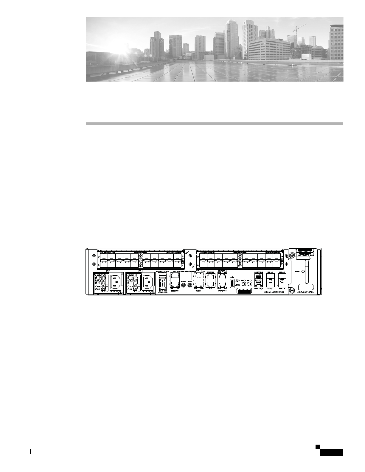
The Cisco ASR 9001 Router is a compact high-capacity provider edge (PE) router that delivers 120
Gbps of non-blocking, full-duplex fabric capacity in a two-rack-unit (2RU) form factor. Similar to other
routers in the Cisco ASR 9000 Series, running Cisco IOS XR software images, the
Cisco ASR 9001 Router delivers the features and services found on the ASR 9000 Series platforms,
allowing customers to standardize on the same Cisco IOS XR image. The Cisco ASR 9001 Router has
an integrated route processor (RP) and two modular bays that support 1 GE and 10 GE modular port
adapters (MPAs). The base chassis has four integrated 10 GE enhanced small form-factor pluggable
(SFP+) ports, a GPS input for stratum-1 clocking, building integrated timing supply (BITS) ports, and
management ports. Figure 1-1 shows the front panel of the Cisco ASR 9001 Router.
Figure 1-1 Front Panel of the Cisco ASR 9001 Router
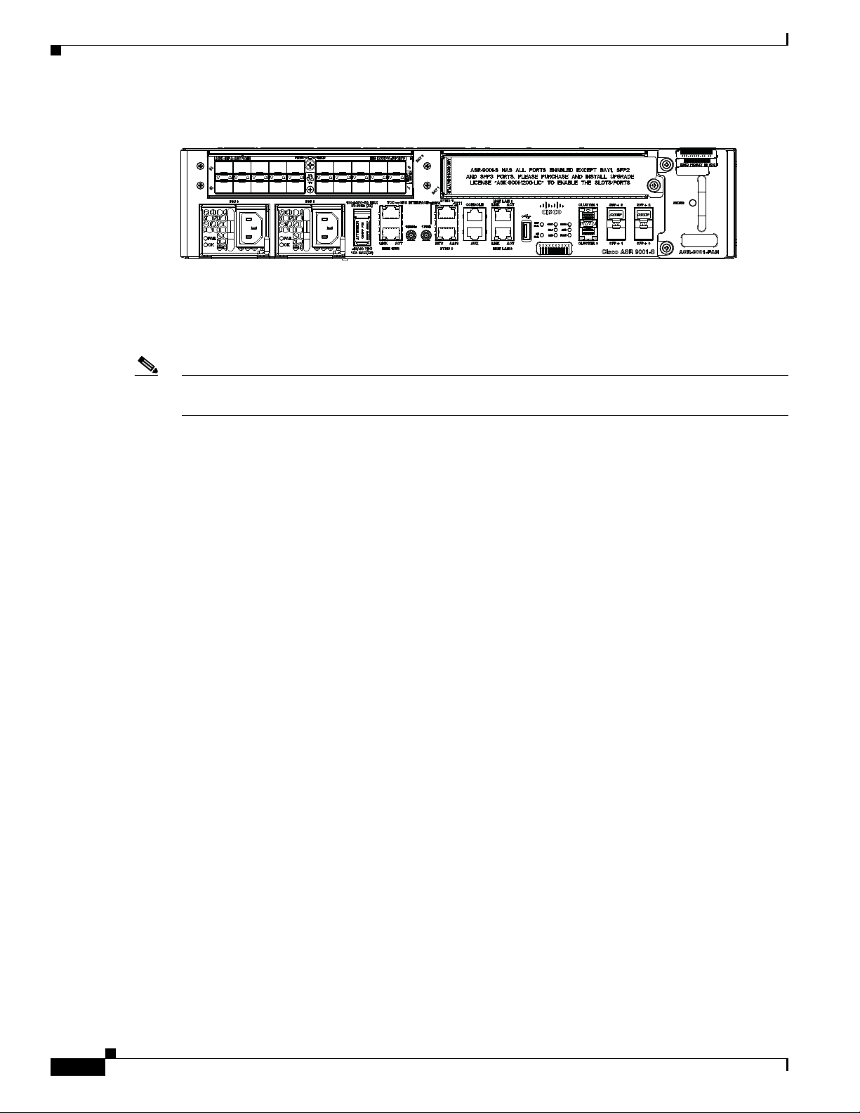
Cisco ASR 9001-S Router
The Cisco ASR 9001-S Router is a 60 Gbps variant of the Cisco ASR 9001 Router. Similar to other
routers in the Cisco ASR 9000 Series, running Cisco IOS XR software images, the
Cisco ASR 9001-S Router delivers the features and services found on the ASR 9000 Series platforms,
allowing customers to standardize on the same Cisco IOS XR image. The Cisco ASR 9001-S Router
comes standard with one modular bay (BAY 0) that supports either a 1 GE, 10 GE, or 40 GE modular
port adapters (MPAs). The chassis also comes usable with two fixed SFP+ ports (SFP+0 and SFP+1).
The second MPA slot (BAY 1) and other two SFP+ ports (SFP+2 and SFP+3) are disabled and covered
with dust caps by default. It supports the same set of features and scaling for each NPU as does the
Cisco ASR 9001 Router. Figure 1-2 shows the front panel of the Cisco ASR 9001-S Router.
OL-26701-02
360033
Cisco ASR 9001 and Cisco ASR 9001-S Routers Hardware Installation Guide
1-1
Page 12
Safety Guidelines
360032
Note The Cisco ASR 9001-S Router follows the same hardware installation procedure as the procedure for the
Chapter 1 Preparing for Installation
Figure 1-2 Front Panel of the Cisco ASR 9001-S Router
In order to achieve the full bandwidth of 120 Gbps and to enable the disabled ports, a Cisco license can
be obtained. Once the license is obtained and installed, the Cisco ASR 9001-S Router must be reloaded
to bring up the full 120 Gbps capacity. For information on configuring the Cisco license for
Cisco ASR 9001-S Router, refer to the Cisco ASR 9001-S 120G Upgrade License Configuration Guide.
Cisco ASR 9001 Router, described in this document.
This chapter guides you through the process of preparing for router installation.
Before installing your Cisco ASR 9001 Router, you must consider these requirements:
• power and cabling requirements must be in place at your installation site
• special equipments must be available for installing the router
• the environmental conditions that your installation site must meet to maintain normal operation
The shipping package for the router is engineered to reduce chances of product damage that may result
from routine material handling during shipment:
• Keep the router in the shipping container until you have determined the installation site.
• The router should always be transported or stored in its shipping package in the upright position.
Inspect all items for shipping damage. If an item appears damaged, contact a Cisco customer service
representative immediately.
This chapter contains these installation topics:
• Safety Guidelines, page 1-2
• Site Requirement Guidelines, page 1-5
• Cisco ASR 9001 Router Port Connection Guidelines, page 1-21
Safety Guidelines
Before you perform any procedure in this publication, you must review the safety guidelines in this
section to avoid injuring yourself or damaging the equipment.
Note that this section contains guidelines, and do not include every potentially hazardous situation.
When you install a router, always use caution and common sense.
General Safety Guidelines
• Never attempt to lift an object that might be too heavy for you to lift by yourself.
Cisco ASR 9001 and Cisco ASR 9001-S Routers Hardware Installation Guide
1-2
OL-26701-02
Page 13

Chapter 1 Preparing for Installation
• Always disconnect the power source and unplug all power cables before lifting, moving, or working
on the router.
• Keep the work area clear and dust free during and after installation.
• Keep tools and router components away from walkways and equipment rack aisles.
• Do not wear loose clothing, jewelry (including rings and chains), or other items that could get caught
in the router.
• Fasten your tie or scarf and sleeves.
• Operate Cisco equipment safely by using it in accordance with its electrical ratings and product
usage instructions.
• Do not work alone if potentially hazardous conditions exist.
• Always unplug power cables when performing maintenance or working on the router, unless the
replacement part is hot swappable and designed for online insertion and removal (OIR).
• Ensure that the installation of the router is in compliance with national and local electrical codes: in
the United States, National Fire Protection Association (NFPA) 70, United States National
Electrical Code; in Canada, Canadian Electrical Code, part I, CSA C22.1; in other countries,
International Electrotechnical Commission (IEC) 364, part 1 through part 7.
Safety Guidelines
Compliance and Safety Information
Both the Cisco ASR 9001 Router and the Cisco ASR 9001-S Router are designed to meet the regulatory
compliance and safety approval requirements. See Regulatory Compliance and Safety Information for
Cisco 12000 Series Routers.
Laser Safety
The line card ports in Cisco ASR 9001 Router are equipped with lasers. The lasers emit invisible
radiation. Do not stare into open line card ports. Observe this warning to prevent eye injury:
Warning
Because invisible laser radiation may be emitted from the aperture of the port when no cable is
connected, avoid exposure to laser radiation and do not stare into open apertures.
Energy Hazard
The Cisco ASR 9001 Router can be configured for a DC power source. Do not touch terminals while
they are live. Observe this warning to prevent injury.
Warning
Hazardous voltage or energy may be present on power terminals. Always replace cover when
terminals are not in service. Be sure uninsulated conductors are not accessible when cover is in
place.
Statement 1086
Statement 70
OL-26701-02
Cisco ASR 9001 and Cisco ASR 9001-S Routers Hardware Installation Guide
1-3
Page 14
Safety Guidelines
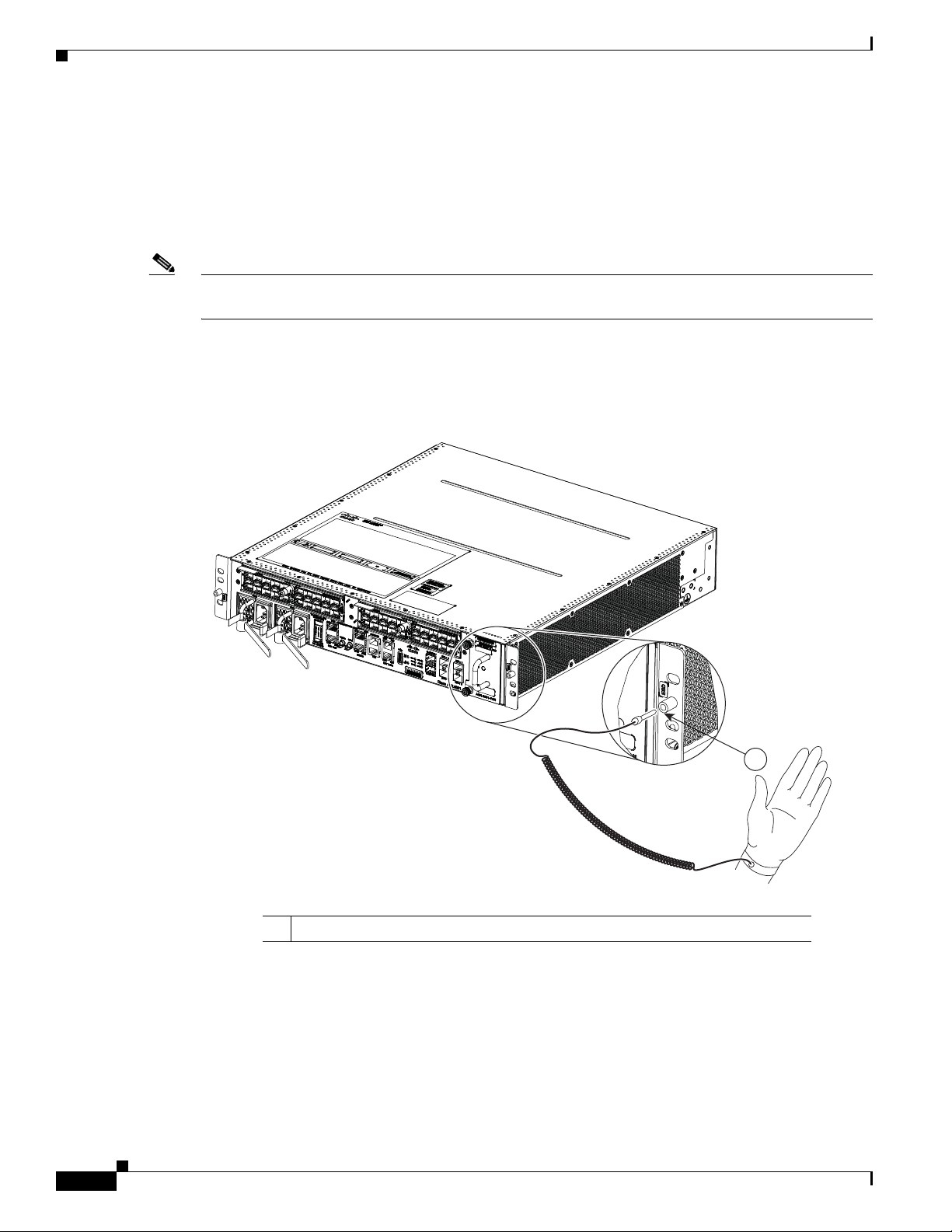
Preventing Electrostatic Discharge Damage
Many router components can be damaged by static electricity. Not exercising the proper electrostatic
discharge (ESD) precautions can result in intermittent or complete component failures. To minimize the
potential for ESD damage, always use an ESD-preventive antistatic wrist strap (or ankle strap) and
ensure that it makes good skin contact.
Note Check the resistance value of the ESD-preventive strap periodically. The measurement should be
between 1 and 10 megohms.
Before you perform any procedure in this guide, attach an ESD-preventive strap to your wrist and
connect the leash to the chassis as shown in Figure 1-3.
Figure 1-3 Connecting an ESD-Preventive Wrist Strap to the Cisco ASR 9001 Router Chassis
Chapter 1 Preparing for Installation
Lifting Guidelines
A fully-configured Cisco ASR 9001 Router can weigh as much as 37.91 pounds (17.2 kg). These
systems are not intended to be moved frequently. Before you install the router, ensure that you have
planned the installation and migration of the router into your network so that you can avoid having to
move the router later to accommodate power sources and network connections.
Use these lifting guidelines to avoid injury to yourself or damage to the equipment:
331880
1
1 Location of chassis socket for ESD strap on the Cisco ASR 9001 Router
1-4
Cisco ASR 9001 and Cisco ASR 9001-S Routers Hardware Installation Guide
OL-26701-02
Page 15

Chapter 1 Preparing for Installation
• Do not lift equipment alone; have another person help you to lift the equipment.
• Ensure that your footing is solid; balance the weight of the object between your feet.
• Lift the equipment slowly; never move suddenly or twist your body as you lift.
• Keep your back straight and lift with your legs, not your back. When bending down to lift
equipment, bend at the knees (not at the waist), to reduce the strain on your lower back muscles.
Site Requirement Guidelines
Warning
To prevent injury and equipment damage, never attempt to lift or tilt the router chassis using the
handles on the fan tray or on line cards. These handles do not support the weight of the chassis.
Site Requirement Guidelines
These sections contain the site requirement guidelines that you should be familiar with before installing
the router:
• Site Wiring Guidelines, page 1-7
• Rack-Mounting and Air Flow Clearance Guidelines, page 1-8
• Chassis Air Flow Guidelines, page 1-7
• Temperature and Humidity Guidelines, page 1-12
• Power Connection Guidelines, page 1-12
• NEBS Supplemental Unit Bonding and Grounding Guidelines, page 1-20
Site Layout and Equipment Dimensions
To help maintain trouble-free operation, adhere to these precautions and guidelines when planning your
rack installation:
• Install the system in a restrictive access location with means for a permanent grounding.
OL-26701-02
• Ensure the site of the rack includes provisions for source AC or DC power, grounding, and network
interface cables.
• Allow sufficient space to work around the rack during the installation. You need at least 3 feet (91.44
cm) adjacent to the rack to move, align, and insert the chassis.
• Maintain at least 24 inches (61 cm) of clearance in front of, and behind the chassis for maintenance
after installation.
• To mount the router between two posts or rails, the usable aperture (the width between the inner
edges of the two mounting flanges) must be at least 17.75 inches (45.09 cm) for the
Cisco ASR 9001 Router.
• Height of the Cisco ASR 9001 Router is 3.47 inches (8.8 cm).
• When fully populated with cards, the router can weigh as much as 37.91 pounds (17.2 kg). To
maintain equipment rack stability and to ensure your safety, the rack is provided with stabilizing
devices. Make sure you install the stabilizers before installing the router.
• If you use a telco-style rack, the weight of the chassis is cantilevered off the two rack posts. Make
sure that:
–
Weight of the router does not make the frame unstable.
Cisco ASR 9001 and Cisco ASR 9001-S Routers Hardware Installation Guide
1-5
Page 16
Site Requirement Guidelines
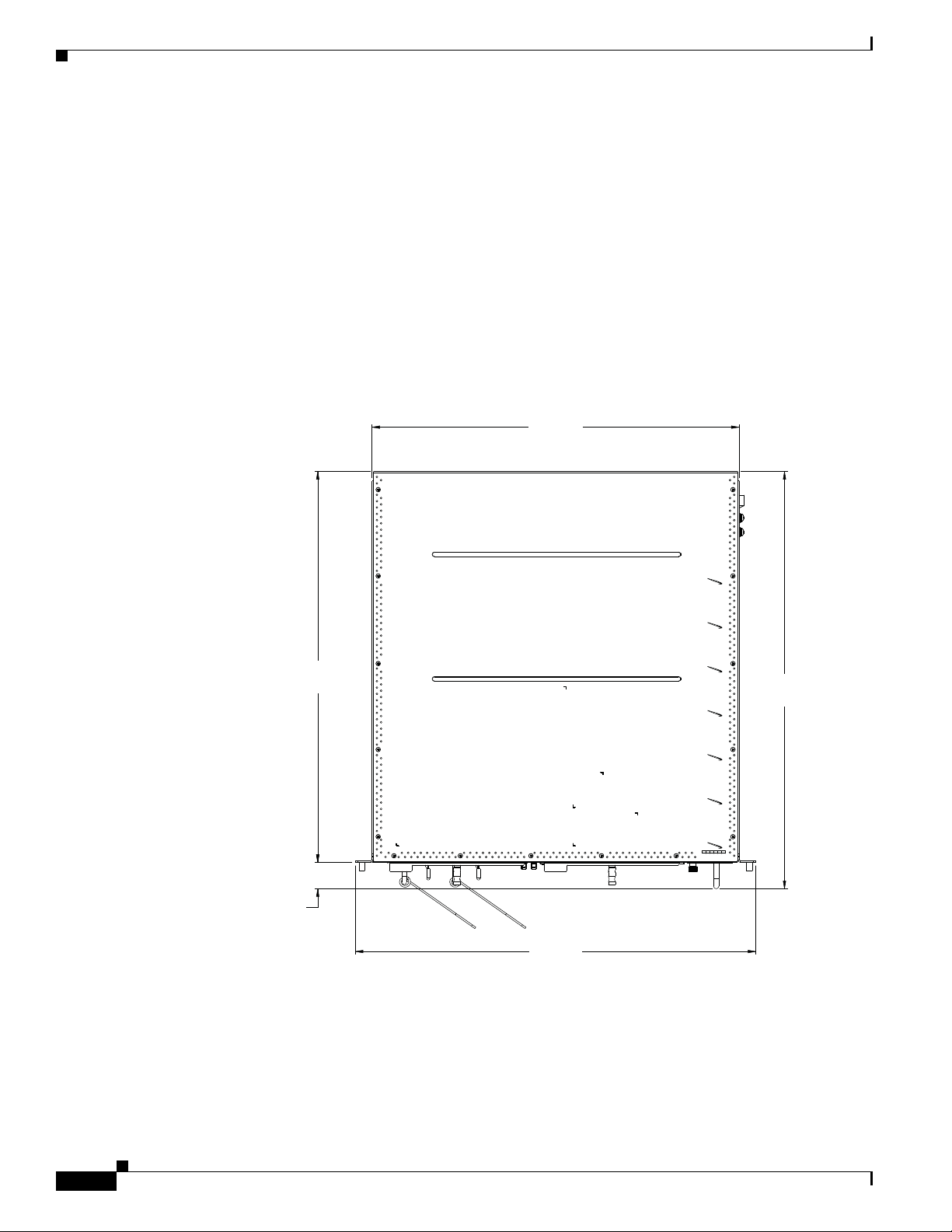
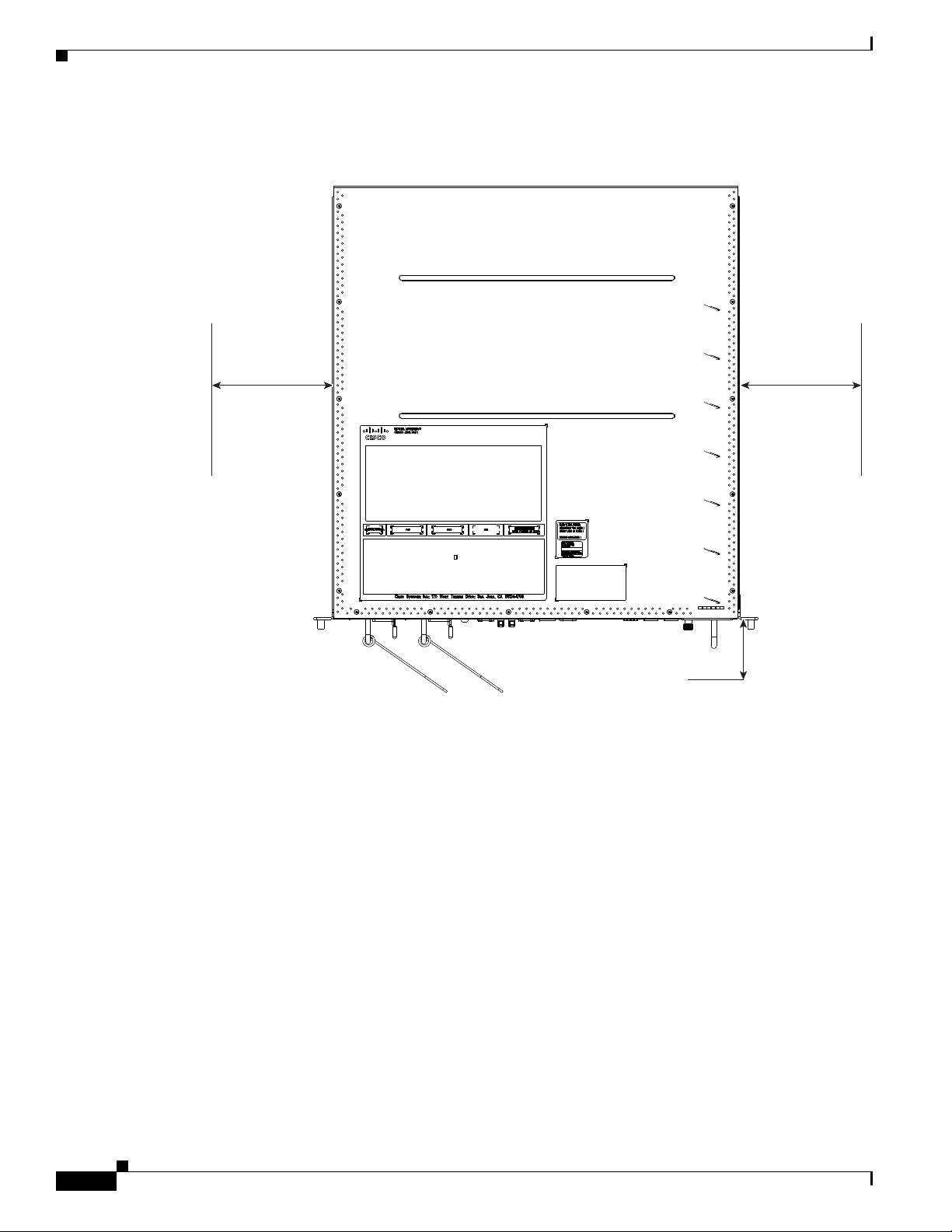
Rear of chassis
Front of chassis
19 inch
(48.3 cm)
17.42 Inch
(44.2 cm)
18.54 Inch
(47.1 cm)
19.79 inch
(50.3 cm)
1.25 inch
(3.2 cm)
• When mounting the router in a telco-style rack or 4-post rack, be sure to use all the screws provided
• Install the cable-management brackets included with the router to keep cables organized. Be sure to
• To avoid noise interference in network interface cables, do not route them directly across or along
Figure 1-4 shows the top-down view chassis dimensions of the Cisco ASR 9001 Router.
Figure 1-4 Cisco ASR 9001 Router Chassis Footprint and Dimensions—Top View
Chapter 1 Preparing for Installation
–
Frame is bolted to the floor and is secured to the building structure using either wall brackets or
overhead brackets.
to secure the chassis to the rack posts.
use appropriate strain-relief methods to protect cables and equipment connections.
power cables.
1-6
Cisco ASR 9001 and Cisco ASR 9001-S Routers Hardware Installation Guide
OL-26701-02
Page 17

Chapter 1 Preparing for Installation
Site Wiring Guidelines
When planning the location of the router, consider distance limitations for signaling, electromagnetic
interference (EMI), and connector compatibility. If the wiring is run for any significant distance in an
electromagnetic field, interference can occur between the field and the signals on the wires. Poor wiring
can cause:
• Radio interference emanating from the wires.
• Strong EMI, especially when caused by lightning or radio transmitters. EMI can destroy the signal
drivers and receivers in the router, and can even create an electrical hazard by conducting power
surges through lines and into equipment.
Note To predict and remedy strong EMI, you may need to consult with radio frequency interference
(RFI) experts.
Site wiring is unlikely to emit radio interference if you use twisted-pair cable with good distribution of
grounding conductors. Use a high-quality twisted-pair cable with one ground conductor for each data
signal, when applicable.
Give special consideration to the effect of lightning strikes in your vicinity, especially if the wiring
exceeds recommended distances, or if it passes between buildings. The electromagnetic pulse (EMP)
caused by lightning or other high-energy phenomena can easily induce enough energy into unshielded
conductors, and destroy electronic devices. If you have experienced EMP problems in the past, you may
want to consult experts in electrical surge suppression and shielding.
Most data centers cannot resolve infrequent, but potentially catastrophic, problems without pulse meters
and other special equipment. In addition, these problems can take a great deal of time to identify and
resolve. We recommend that you take the necessary precautions to avoid these problems by providing a
properly grounded and shielded environment, with special attention to issues of electrical surge
suppression.
Site Requirement Guidelines
Chassis Air Flow Guidelines
Cool air is circulated through the Cisco ASR 9001 Router by one fan tray located along the right side of
the router (see Figure 1-5).
The fan tray maintains acceptable operating temperatures for the internal components by drawing in cool
air through the vents, and circulating the air through the chassis. Each power supply is also equipped
with fans that draw cool air into the front of the power supply and force warm air out of the air exhaust.
Note See the “Rack-Mounting and Air Flow Clearance Guidelines” section on page 1-8 section for details on
air flow clearance requirements for installation in an enclosed 4-post rack.
OL-26701-02
Cisco ASR 9001 and Cisco ASR 9001-S Routers Hardware Installation Guide
1-7
Page 18
Site Requirement Guidelines
Figure 1-5 Air Flow Path through the Cisco ASR 9001 Router
Chapter 1 Preparing for Installation
Air exhaust
When selecting a site to install the router, observe these guidelines:
• Dust free area—Site should be as dust free as possible. Dusty environments can clog the power
supply intake vents, reducing the cooling air flow through the router. Clogged filters and vents can
cause an over-temperature condition in the router.
• Unrestricted air flow—Allow sufficient air flow by maintaining a minimum of 6 inches (15.24 cm)
of clearance at both the inlet and exhaust openings on the chassis and the power modules. If the air
flow is blocked or restricted, or if the inlet air is too warm, an over-temperature condition can occur
within the router. Under extreme conditions, the environmental monitoring system powers off the
router to protect the components.
See “Rack-Mounting and Air Flow Clearance Guidelines” for details on air flow clearance requirements
for installation in an enclosed 4-post rack.
Rack-Mounting and Air Flow Clearance Guidelines
The router can be mounted in most 2-post, 4-post, or telco-style 19-inch equipment racks that comply
with the Electronics Industries Association (EIA) standard for equipment racks (EIA-310-D). The rack
must have at least two posts with mounting flanges to mount the router chassis. The distance between
the center lines of the mounting holes on the two mounting posts must be 18.31 inches ± 0.06 inch
(46.50 cm ± 0.15 cm).
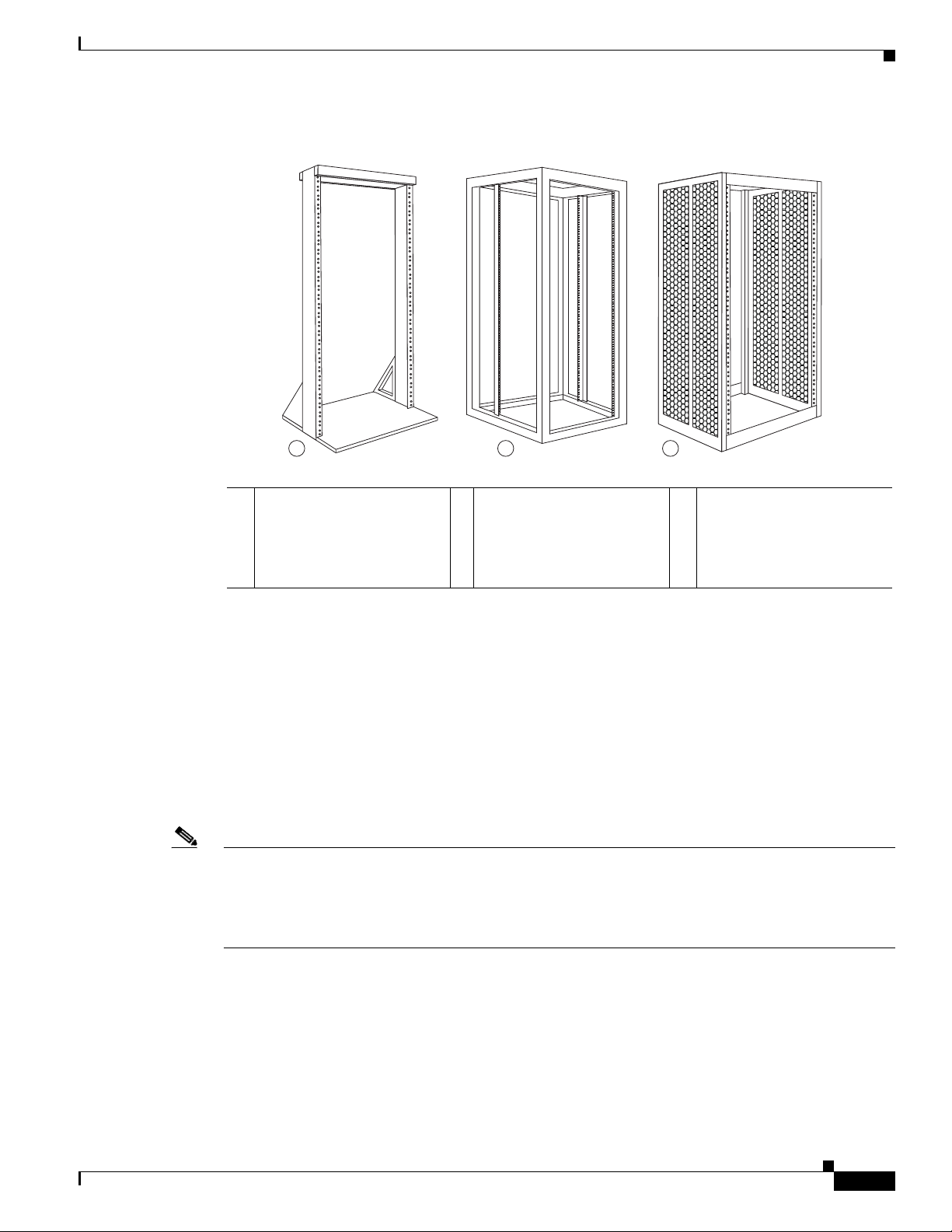
Figure 1-6 shows examples of typical 2-post, 4-post, and telco-type equipment racks.
Room air
331882
1-8
Cisco ASR 9001 and Cisco ASR 9001-S Routers Hardware Installation Guide
OL-26701-02
Page 19
Chapter 1 Preparing for Installation
243453
a b c
Figure 1-6 Equipment Rack Types
Site Requirement Guidelines
Telco 2-Post Rack
Note The mounting brackets on the Cisco ASR 9001 Router chassis have a pair of holes at the top and bottom
a Telco-style rack b Free-standing, 4-post open
rack with two mounting
posts in the front, two
mounting posts in the back
c Free-standing enclosed rack
with perforated sides and
two mounting posts in the
front
or along each side
Item a in Figure 1-6 shows a telco-style rack. The telco-style rack is an open frame consisting of two
posts tied together by a cross-bar at the top and a floor-stand at the bottom.
This type of rack is usually secured to the floor, and sometimes to an overhead structure or wall for
additional stability. The router chassis can be installed in the telco-style rack only in a front-mounted
position.
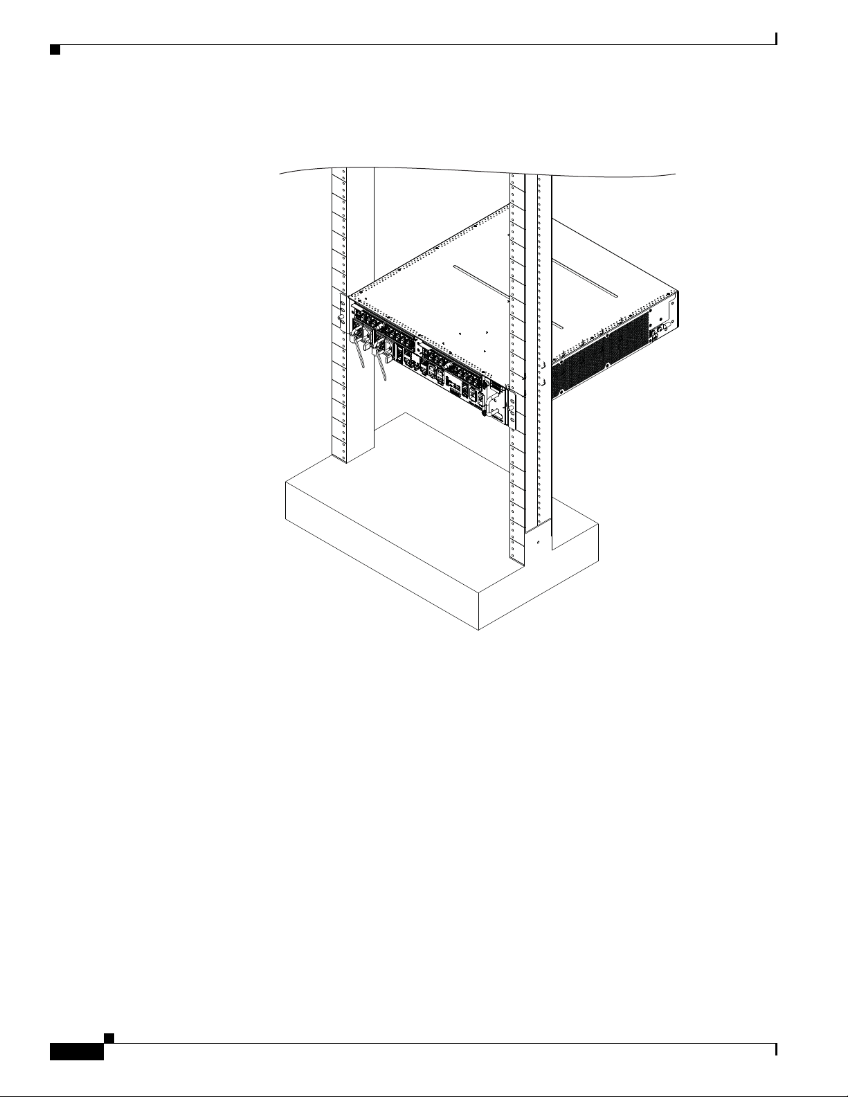
In the front-mounted position, you secure the chassis rack-mounting brackets directly to the rack posts
(see Figure 1-7 as an example of a Cisco ASR 9001 Router rack mounting). Two rear mounting brackets
are provided for mounting the Cisco ASR 9001 Router in a 2-post rack.
of each bracket; the remaining openings in the brackets are slots. If the Cisco ASR 9001 Router is to be
mounted in a 2-post 19-inch rack, you must first use the holes to locate and position the brackets on the
rack. Insert screws through the bracket holes into the rack before inserting screws through the bracket
slots.
OL-26701-02
Cisco ASR 9001 and Cisco ASR 9001-S Routers Hardware Installation Guide
1-9
Page 20
Site Requirement Guidelines
331928
Figure 1-7 Cisco ASR 9001 Router Mounted in a 2-Post Rack
Chapter 1 Preparing for Installation
Open 4-Post Rack
Item b in Figure 1-6 shows a free-standing, 4-post open rack with two mounting posts in the front and
two mounting posts in the back or along the side. The mounting posts in this type of rack are often
adjustable so that you can position the rack-mounted unit within the depth of the rack rather than
flush-mount it with the front of the rack.
Two rear mounting brackets are provided for mounting the Cisco ASR 9001 Router in a 4-post rack.
Enclosed Rack with Perforated Sides
Item c in Figure 1-6 shows a free-standing 4-post enclosed rack with perforated sides and two mounting
posts in the front.
Cisco ASR 9001 and Cisco ASR 9001-S Routers Hardware Installation Guide
1-10
OL-26701-02
Page 21

Chapter 1 Preparing for Installation
Caution Do not install the Cisco ASR 9001 Router in any type of fully-enclosed rack that does not have the
required perforated sides or doors; the router requires an unobstructed flow of cooling air to maintain
acceptable operating temperatures for its internal components. Installing the router in any type of
fully-enclosed rack without proper perforation could disrupt the air flow, trap heat next to the chassis,
and cause an over-temperature condition inside the router.
Air Flow Guidelines for Enclosed Rack Installation
To install a Cisco ASR 9001 Router in a 4-post enclosed cabinet, the front and rear doors of the cabinet
must be removed or be perforated with a minimum of 65% open area (70% for ETSI 800mm racks).
If you are mounting the chassis in a 4-post enclosed cabinet, ensure that you have these clearances aound
the chassis:
• Rear: Minimum of 3.15 inches (8.00 cm) of clearance
• Sides: Minimum of 6 inches (15.24 cm) of clearance on each side of the chassis.
Figure 1-8 shows the side and rear chassis air flow clearance requirements for mounting the
Cisco ASR 9001 Router in a 4-post enclosed rack.
Site Requirement Guidelines
OL-26701-02
Cisco ASR 9001 and Cisco ASR 9001-S Routers Hardware Installation Guide
1-11
Page 22
Site Requirement Guidelines
Figure 1-8 ASR 9001 Clearance Requirements for an Enclosed 4-Post Rack Installation
Chapter 1 Preparing for Installation
Rear of chassis
6 Inches
152.0 mm
Temperature and Humidity Guidelines
Front of chassis
3.25 Inches
82.55 mm
6 Inches
152.0 mm
331929
The operating and nonoperating environmental site requirements are listed in Tab l e A-2. The router
normally operates within the ranges listed in Tab le A-3; however, if a temperature measurement is
approaching a minimum or maximum parameter, it indicates a potential problem. Maintain normal
operation by anticipating and correcting environmental anomalies before they approach critical values,
by properly planning and preparing your site before you install the router.
Power Connection Guidelines
You can configure the router with either an AC-input or DC-input power subsystem, so the site power
source requirements differ depending on the power subsystem in your router. Ensure all power
connection wiring conforms to the rules and regulations in the National Electrical Code (NEC) as well
as local codes.
Cisco ASR 9001 and Cisco ASR 9001-S Routers Hardware Installation Guide
1-12
OL-26701-02
Page 23
Chapter 1 Preparing for Installation
Caution Each Cisco ASR 9001 Router is powered by only one type of input: AC or DC. A hybrid (AC+DC)
power configuration is not supported.
Caution Proper grounding is necessary to avoid damage from lightning and power surges. See the “NEBS
Supplemental Unit Bonding and Grounding Guidelines” section on page 1-20 for grounding
requirements.
AC Powered Routers
AC power modules operate in the input range of 100 VAC to 240 VAC, 50 to 60 Hz and require a
minimum service of:
• 15 A for operation in North America and Japan
• 10 A for international operation
• 13 A for operation in the UK
Site Requirement Guidelines
Each of the AC power inputs requires a separate dedicated branch circuit. For a list of the nominal and
acceptable value ranges for source AC power, see Tab le A-5.
Table 1-1 lists the AC-input power cord options, specifications, and Cisco product numbers for the
AC-input power supply modules. Tab le 1-1 also references power cord illustrations. For more
information on Cisco product numbers (PIDs) and their detailed description of power cords, refer to
Dynamic Configuration Tool.
Table 1-1 AC-Input Power Cord Options for ASR 9001 Router
Locale Part Number Length
Power Cord
Rating
Reference
Illustration
USA CAB-AC 8.2 feet (2.5 m) 15 A, 250 V Figure 1-9
Japan CAB-L620P-C13-JPN 8.2 feet (2.5 m) 15 A, 250 V Figure 1-10
Australia CAB-ACA 8.2 feet (2.5 m) 10 A, 250 V Figure 1-11
Italy CAB-ACI 8.2 feet (2.5 m) 10 A, 250 V Figure 1-12
Argentina CAB-ACR 8.2 feet (2.5 m) 10 A, 250 V Figure 1-13
Switzerland CAB-ACS 8.2 feet (2.5 m) 10 A, 250 V Figure 1-14
UK CAB-ACU 8.2 feet (2.5 m) 13 A, 250 V Figure 1-15
China CAB-ACC 8.2 feet (2.5 m) 10 A, 250 V Figure 1-16
South Africa/India CAB-ACSA 8.2 feet (2.5 m) 10 A, 250 V Figure 1-17
Europe CAB-9K10A-EU 8.2 feet (2.5 m) 10 A, 250 V Figure 1-18
Israel SFS-250V-10A-IS 8.2 feet (2.5 m) 10 A, 250 V Figure 1-19
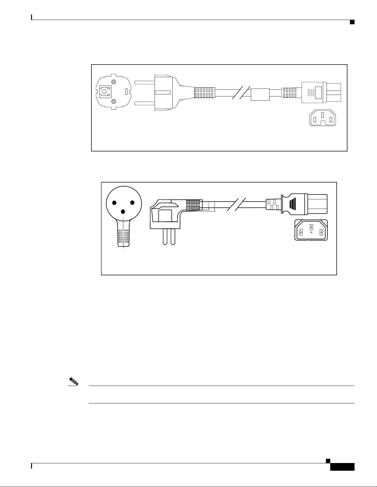
AC Power Cord Illustrations
This section contains the AC power cord illustrations, as described in Table 1-1. Note that an AC power
cord may be used with several power supplies.
OL-26701-02
Cisco ASR 9001 and Cisco ASR 9001-S Routers Hardware Installation Guide
1-13
Page 24
Site Requirement Guidelines
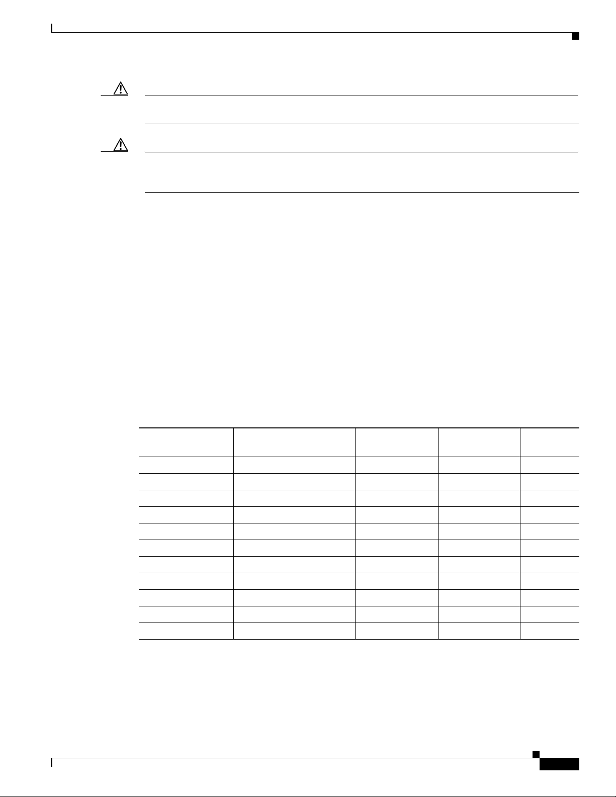
Cordset rating: 15 A, 250 V
Length: 8 ft 2 in. (2.5 m)
Connector: WS 002
Plug: NEMA L6-20P
332009
Figure 1-9 AC Power Cord CAB-AC
Figure 1-10 AC Power Cord CAB-L620P-C13-JPN
Plug: EL701B
Chapter 1 Preparing for Installation
Cordset rating: 15 A, 250 V
Length: 8 ft 2 in. (2.5 m)
Connector: IEC 60320 C13
332012
1-14
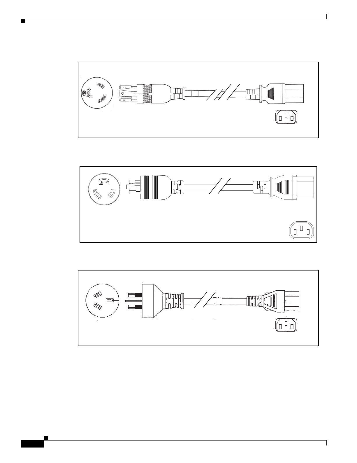
Figure 1-11 AC Power Cord CAB-ACA
Cordset rating: 10 A, 250 V
Length: 8 ft 2 in. (2.5 m)
Plug: NEMA L6-20
Cisco ASR 9001 and Cisco ASR 9001-S Routers Hardware Installation Guide
Connector: IEC 60320 C13
332013
OL-26701-02
Page 25
Chapter 1 Preparing for Installation
Cordset rating: 10 A, 250 V
Length: 8 ft 2 in. (2.5 m)
Connector: IEC 60320 C13
Plug: CEI 23-16
332008
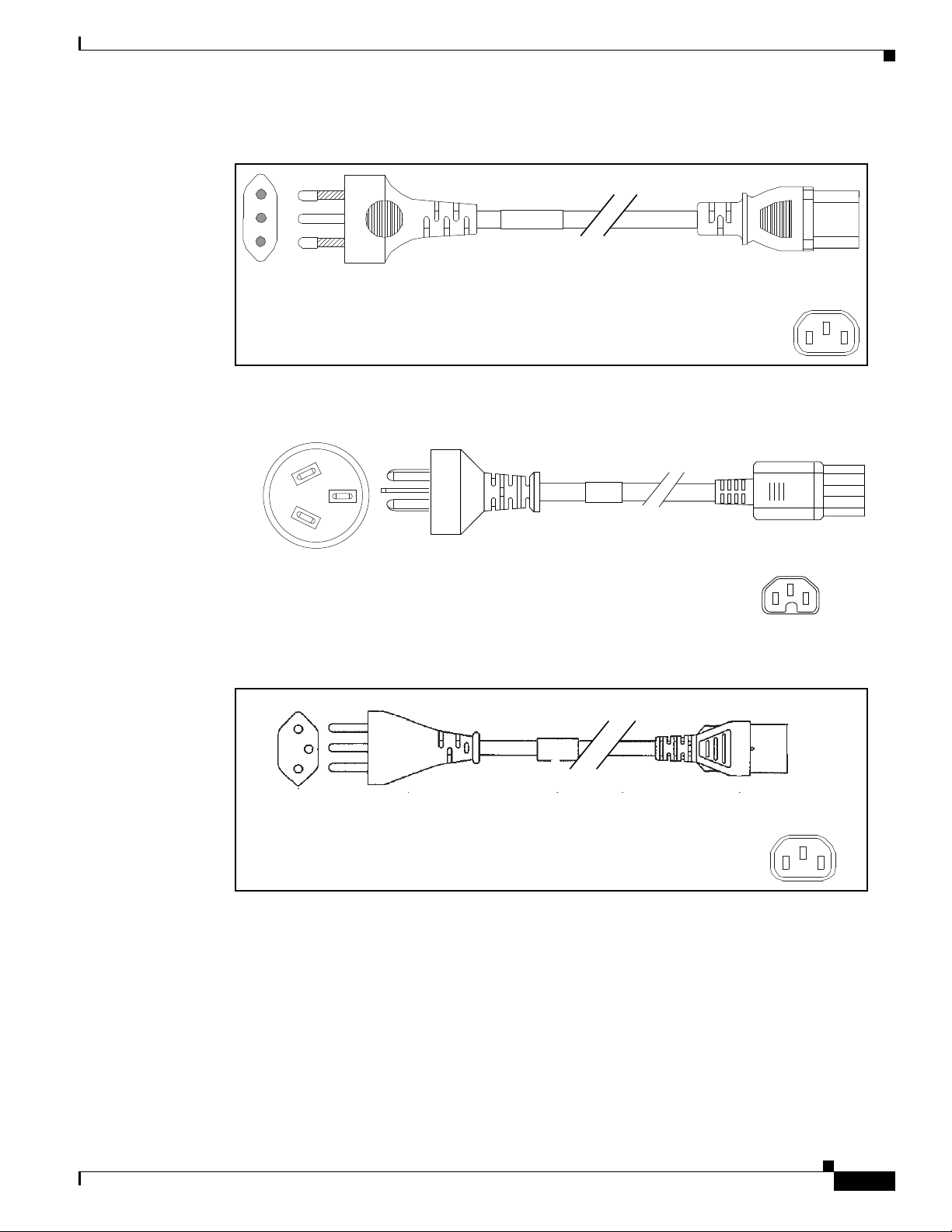
Cordset rating: 10 A, 250 V
Length: 8 ft 2 in. (2.5 m)
Connector: WS 002
Plug: NEMA L6-20P
332011
Figure 1-12 AC Power Cord CAB-ACI
Figure 1-13 AC Power Cord CAB-ACR
Site Requirement Guidelines
Plug: EL 219 (IRAM 2073)
Figure 1-14 AC Power Cord CAB-ACS
Cordset rating: 10 A/250 V
Length: 8 ft 2 in. (2.5 m)
Connector: IEC 60320 C13
285303
OL-26701-02
Cisco ASR 9001 and Cisco ASR 9001-S Routers Hardware Installation Guide
1-15
Page 26
Site Requirement Guidelines
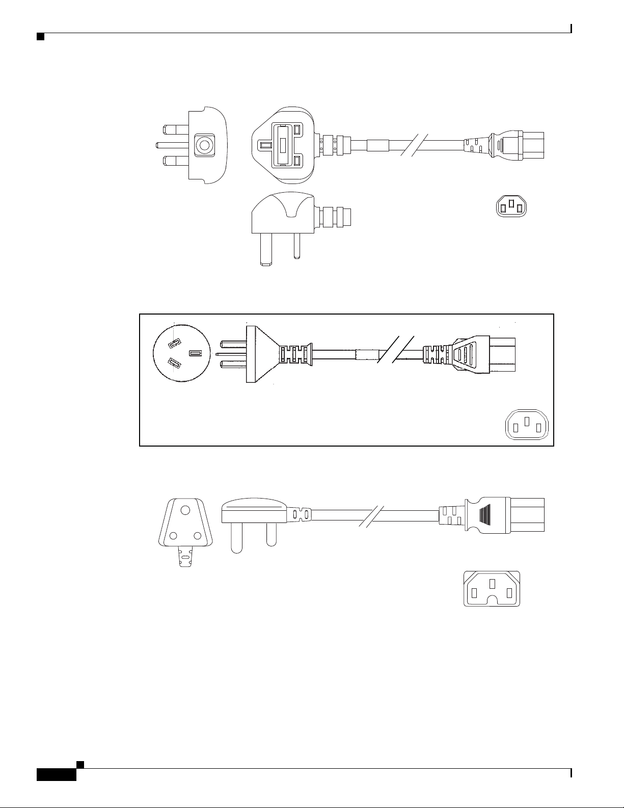
Cordset rating: 10 A, 250 V
Length: 8 ft 2 in. (2.5 m)
Connector: WS 002
Plug: NEMA L6-20P
332010
285302
Connector: IEC 60320 C15
Plug: EL 208
(SABS 164-1)
Cordset rating: 10 A, 250 V
Length: 8 ft 2 in. (2.5 m)
Figure 1-15 AC Power Cord CAB-ACU
Figure 1-16 AC Power Cord CAB-ACC
Chapter 1 Preparing for Installation
Cordset rating: 13 A, 250 V
Length: 8 ft 2 in. (2.5 m)
Plug: BSI 1363
Connector: IEC 60320 C13
285301
1-16
Figure 1-17 AC Power Cord CAB-ACSA
Cisco ASR 9001 and Cisco ASR 9001-S Routers Hardware Installation Guide
OL-26701-02
Page 27
Chapter 1 Preparing for Installation
Connector: WS 002
Cordset rating: 10A, 250 V
Length: 8 ft 2 in. (2.5 m)
Plug:
M2511
Figure 1-18 AC Power Cord CAB-9K10A-EU
Figure 1-19 AC Power Cord SFS-250V-10A-IS
Site Requirement Guidelines
DC Powered Router
Connections to DC power modules are rated at 20 A maximum. The system accepts a nominal input voltage
of –48 VDC with an operational tolerance range of –48 VDC to –60 VDC. One dedicated, commensurately
rated DC power source is required for each power module connection.
Power connections to the each DC power module requires two cables: one source cable and one return
cable.
For DC power cables, we recommend that you use 20-A-rated, high-strand-count copper wire cables.
The length of the cables depends on your router location from the source power.
Note DC power cables are not available from Cisco, but they are available from external commercial cable
vendors.
Cordset rating: 10 A, 250V
Length: 8 ft 2 in. (2.5 m)
Connector: WS 002
Plug:
EL 212
(SI-32)
332624
OL-26701-02
You must terminate DC power cables using terminal blocks. The terminal blocks are supplied along with
the DC power supply modules from Cisco. The terminal block part number is PC 5/2-STF-7.62 BD:+,from Phoenix contact.
Cisco ASR 9001 and Cisco ASR 9001-S Routers Hardware Installation Guide
1-17
Page 28
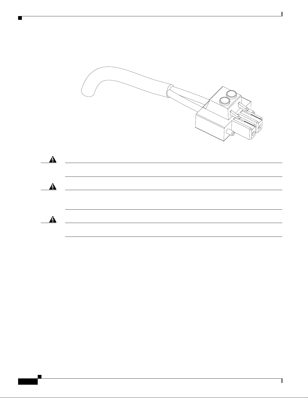
Site Requirement Guidelines
Figure 1-20 shows the type of terminal block required for DC-input cable connections.
Figure 1-20 DC Power Cable Terminal Block
Figure 1-21 shows DC power source cable connections for single DC power module.
Chapter 1 Preparing for Installation
Warning
Warning
Warning
To avoid shock hazard, be sure to apply shrink wrap tubing around the wire entry area of the terminal
block.
Hazardous voltage or energy may be present on power terminals. Always replace cover when
terminals are not in service. Be sure uninsulated conductors are not accessible when cover is in
place.
Statement 1086
Only trained and qualified personnel should be allowed to install, replace, or service this equipment.
Statement 1030
1-18
Cisco ASR 9001 and Cisco ASR 9001-S Routers Hardware Installation Guide
OL-26701-02
Page 29
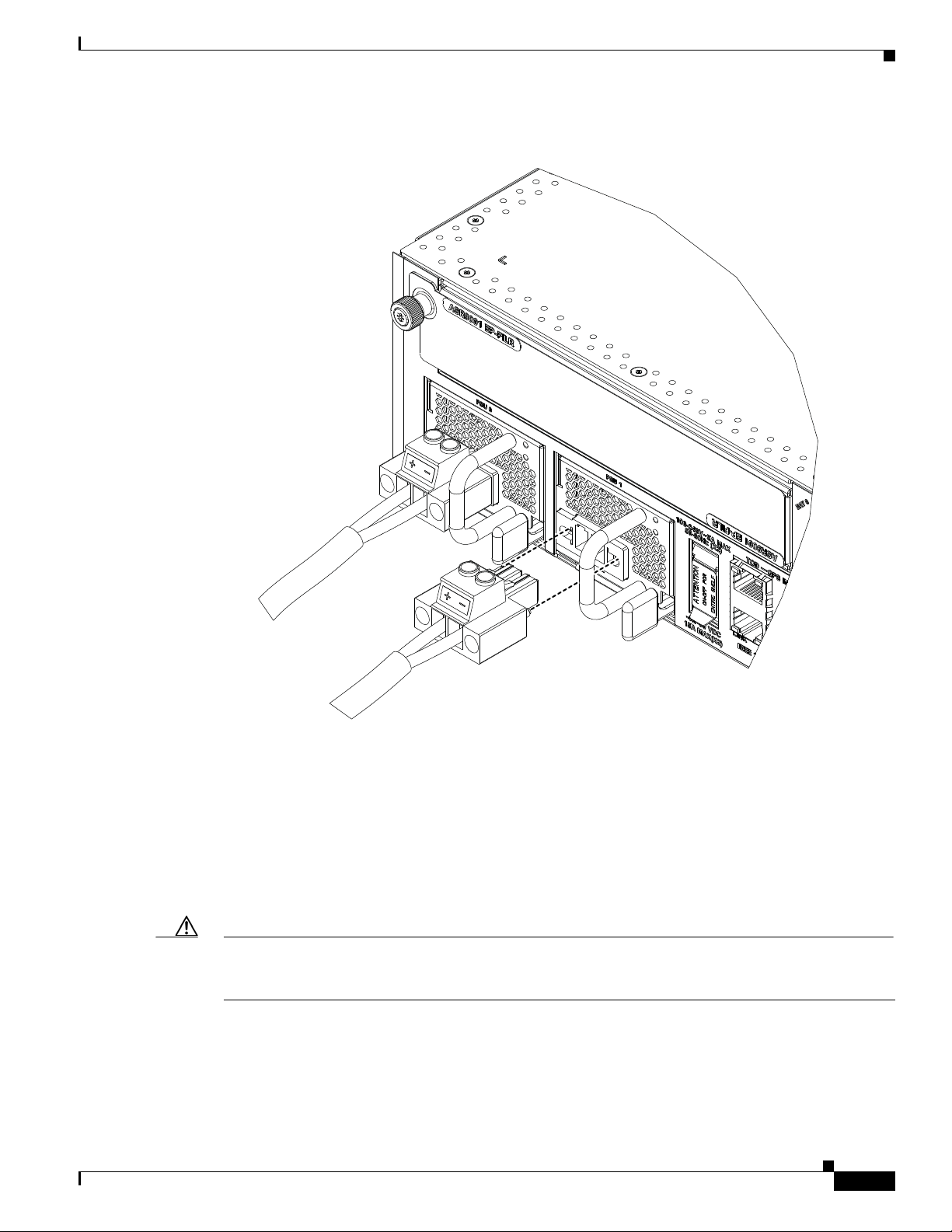
Chapter 1 Preparing for Installation
Figure 1-21 DC Power Source Cabling Scheme for a Single DC Power Module
Site Requirement Guidelines
331933
The color coding of the source DC power cable leads depends on the color coding of the site DC power
source. Because there is no color code standard for source DC wiring, be sure that power source cables
are connected to the power modules using the proper positive (+) and negative (–) polarity:
• In some cases, the source DC cable leads might have a positive (+) or a negative (–) label. This is a
relatively safe indication of the polarity, but you must also verify the polarity by measuring the
voltage between the DC cable leads. Be sure that the positive (+) and negative (–) cable leads match
the positive (+) and negative (–) labels on the power module when making the measurement.
• Green (or green and yellow) cable typically indicates that it is a ground cable.
Caution DC power modules contain reverse voltage protection circuitry to prevent damage to the power module
if it detects a reverse polarity condition. No damage should occur from reverse polarity, but you should
correct a reverse polarity condition immediately.
For a list of the nominal and acceptable value ranges for source DC power, see Table A-4 on page A-3.
OL-26701-02
Cisco ASR 9001 and Cisco ASR 9001-S Routers Hardware Installation Guide
1-19
Page 30
Chapter 1 Preparing for Installation
Site Requirement Guidelines
NEBS Supplemental Unit Bonding and Grounding Guidelines
Although the router chassis requires a safety earth ground connection as part of the power cabling to
power modules, you must permanently connect the central office ground system or interior equipment
grounding system to the supplemental bonding and grounding connection on the side of the router
chassis to meet network equipment building system (NEBS) requirements as well as safety compliance
requirements. These grounding points are referred to as the NEBS bonding and grounding points.
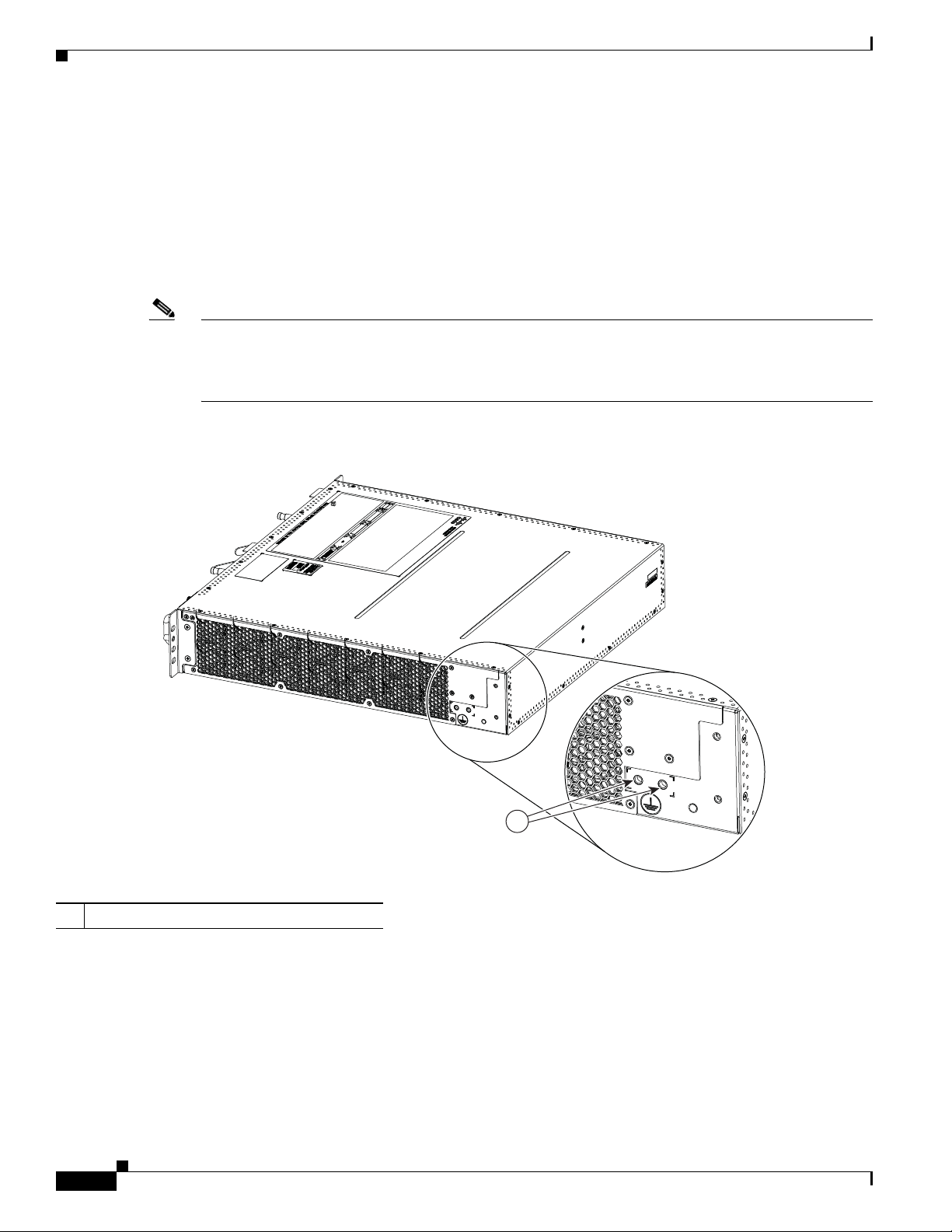
Figure 1-22 shows the NEBS grounding locations for the Cisco ASR 9001 Router.
Note These bonding and grounding connections satisfy the Telcordia NEBS requirements for supplemental
bonding and grounding connections. If you are not installing the router in a NEBS environment, you can
choose to bypass these guidelines and rely on the safety earth ground connections to the AC or DC power
modules.
Figure 1-22 NEBS Bonding and Grounding Points on the Cisco ASR 9001 Router
1 NEBS grounding point on side of chassis
To ensure a satisfactory supplemental ground connection to the router, use these parts:
• One grounding lug, which has two M6 bolt holes with 0.625- to 0.75-inch (15.86- to 19.05-mm)
spacing between them, and a wire receptacle large enough to accept a six AWG or larger, multistrand
copper wire. For four AWG cable, use Panduit part number LCD4-14AF-L; for six AWG, use
Panduit part number LCD6-14AF-L.
• Two 10-32 round-head screws and two locking washers (nickel-plated brass is ideal).
Cisco ASR 9001 and Cisco ASR 9001-S Routers Hardware Installation Guide
1-20
1
332017
OL-26701-02
Page 31

Chapter 1 Preparing for Installation
1 3 4 5 6 687
332426
92
Cisco ASR 9001 Router Port Connection Guidelines
• One grounding wire. Although we recommend at least six AWG multistrand copper wire, the wire
diameter and length depend on your router location and site environment.
Note These parts are not available from Cisco, but they are available from external commercial vendors.
Cisco ASR 9001 Router Port Connection Guidelines
This section contains detailed cabling and signal information for all interface and port connections to the
RP. It also provides information for Ethernet routing and equipment.
Caution Ports labeled Ethernet, SYNC, CONSOLE, and AUX are safety extra-low voltage (SELV) circuits. SELV
circuits should only be connected to other SELV circuits.
Note In Cisco ASR 9001-S Router, two 10 GE fixed SFP+ ports (SFP+2 and SFP+3) are disabled by default,
and can be enabled by a license upgrade.
Figure 1-23 shows all the port connections on the front panel of the Cisco ASR 9001 Router.
Figure 1-23 Cisco ASR 9001 Router Front Panel Ports
1 Service LAN and ToD ports 6 External USB port
2 10MHz and 1PPS indicators 7 Eight discrete LED indicators
3 SYNC (BITS/J.211) ports 8 CLUSTER ports
4 CONSOLE and AUX ports 9 Fixed SFP+ ports
5 Management LAN ports
OL-26701-02
Table 1-2 lists the Cisco ASR 9001 Router front panel ports description.
Cisco ASR 9001 and Cisco ASR 9001-S Routers Hardware Installation Guide
1-21
Page 32

Cisco ASR 9001 Router Port Connection Guidelines
Port Name Connector Type Description
TOD Port RJ45 Time of Day Input/Output Port along with 1PPS
Service LAN Port (IEEE
1588)
10MHz Connector SMB 10MHz Input for GPS Synchronization. This signal
1PPS Connector SMB 1PPS Input for GPS Synchronization. This signal can
SYNC Ports (SYNC
0/SYNC 1)
CONSOLE Port RJ45 Local Craft Terminal for connecting the box with PC.
AUX Port RJ45 Local Craft Terminal with modem handshaking
Management LAN Ports
(MGT LAN 0/1)
USB Port USB TYPE-A
Chapter 1 Preparing for Installation
Table 1-2 Cisco ASR 9001 Router Front Panel Ports Description
Signal. Signal type is RS422.
RJ45 A 10/100Mbps Ethernet Port for IEEE1588 Grand
Master Connection through CAT5 cable. Signal type is
MLT3.
can provide 10MHz output as well from Cisco ASR
9001 Router. Signal type is sinusoidal.
provide output as well from Cisco ASR 9001 Router.
Signal type is square wave.
RJ45 Used as BITS or DTI (one at a time) Input/Output Port
based on the configuration used. CAT5 ethernet cable
can be used for DTI. In DTI mode link resembles an
Ethernet (802.3) 10BaseT link. Signal type depends
on the mode such as B8ZS for T1, HDB3 for E1,
Manchester Coded Data for DTI, Sinusoidal for
6.3128 Out.
Used to command the CPU and to collect CPU log.
This console port operates at default 115200 baud rate
however other standard baud rates can be configured
through confreg setting at Rommon. Signal type is
RS232.
signals. This port operates at default 115200 baud rate
however other standard baud rates can be configured
through confreg setting at Rommon. The hardware has
design option (through IMIO FPGA) to connect the
AUX port with RP CPU or LC CPU. This can be used
as console port for the LC CPU. Signal type is RS232.
RJ45 Management Port for TFTP boot. It is a tri speed
(10/100/1000 Mbps) Ethernet port with auto
negotiation enabled. Connection through CAT5E
cable. Signal type is 8B/10B for 1G, MLT3 for 100
Mbps, Manchester coded for 10 Mbps.
For connecting USB Device. This port can be used to
Receptacle
upload installable modules, temporary binaries,
scripts etc through USB disk. Also, it can be used to
transfer router log from the internal eUSB to the
external memory stick. Signal type is NRZI.
1-22
Cisco ASR 9001 and Cisco ASR 9001-S Routers Hardware Installation Guide
OL-26701-02
Page 33

Chapter 1 Preparing for Installation
Cisco ASR 9001 Router Port Connection Guidelines
Table 1-2 Cisco ASR 9001 Router Front Panel Ports Description
Port Name Connector Type Description
CLUSTER Ports (0/1) SFP For Cascading two Cisco ASR 9001 Router systems.
The pinout and signal level is as per the SFP standard.
This supports copper/optical SFP modules.
Fixed SFP+ Ports (0/1/2/3) SFP+ Fixed ports include 4X10G SFP+ ports and supports
20X1G, 4X10G and 2X10G ports through Ethernet
Plugs.
Console Port and Auxiliary Port Connection Guidelines
The RP has two EIA/TIA-232 (formerly RS232) serial RJ-45 connection ports (see Figure 1-23):
• Console port—RJ-45 interface for connecting a data terminal device to the router, which you need
to perform the initial configuration of the router.
• Auxiliary port—RJ-45 interface for connecting a modem.
Note The console and auxiliary ports are asynchronous serial ports. Ensure that devices connected to
Console Port Signals
The RP console port is an RJ-45 interface for connecting a terminal to the router. The console port does
not support modem control or hardware flow control and requires a straight-through RJ-45 cable.
Before connecting a terminal to the console port, check the terminal setting for the data transmission
rate, in bits per second (bps). The terminal transmission rate setting must match the default rate of the
RP console port, which is 115200 bps. Set the terminal to these operational values: 115200 bps, 8 data
bits, no parity, 1 stop bits (115200 8N1).
Table 1-3 lists the signals used on the RP console port.
Table 1-3 RP Console Port Signals
Console Port Pin Signal Input/Output Description
these ports are capable of asynchronous transmission.
1 RTS Output Request to Send
2 — — (Not connected)
3 TxD Output Transmit data
4 GND — Signal ground
5 GND — Signal ground
6 RxD Input Receive data
7 — — (Not connected)
8 CTS Input Clear to Send
OL-26701-02
Cisco ASR 9001 and Cisco ASR 9001-S Routers Hardware Installation Guide
1-23
Page 34

Cisco ASR 9001 Router Port Connection Guidelines
Auxiliary Port Signals
The RP Auxiliary (AUX) port is a RJ-45 interface for connecting a modem or other data communication
equipment (DCE) device (such as another router) to the RP. The AUX port supports hardware flow
control and modem control.
Table 1-4 lists the signals used on the Auxiliary port.
Table 1-4 RP AUX Port Signals
AUX Port Pin Signal Input/Output Description
1 RTS Output Request to send
2 DTR Output Data terminal ready
3 TxD Output Transmit data
4 GND — Signal ground
5 GND — Signal ground
6 RxD Input Receive data
7 DSR Input Data set ready
8 CTS Input Clear to send
Chapter 1 Preparing for Installation
Management LAN Ports Connection Guidelines
The RP has two RJ45 media-dependent interface (MDI) Ethernet management LAN ports: MGT LAN 0
and MGT LAN 1 (see Figure 1-23).
These ports are used for IEEE 802.3 10BASE-T (10 Mbps), IEEE 802.3u 100BASE-TX (100 Mbps), or
1000BASE-T (1000 Mbps) Ethernet connections.
The transmission speed of the management LAN ports is not user-configurable. The transmission speed
is set through an auto-sensing scheme on the RP; the speed is determined by the network to which that
the Ethernet port is connected. The combined total input rate of both MGT LAN 0 and MGT LAN 1 is
about 12 Mbps.
Management port characteristics are:
• Maximum transmission unit (MTU) is fixed at 1514 and cannot be configured.
• Flow control is disabled and cannot be configured.
• Input unicast packets with an unknown destination address are filtered and dropped.
• Autonegotiation of port speed (10/100/1000) and duplex (full/half) is supported. Autonegotiation
cannot be disabled.
Table 1-5 lists the signals used on the Management LAN ports.
Table 1-5 RP Management LAN Port Signals
MGT LAN Port Pin 10Base-T, 100Base-TX Signal 1000Base-T Signal
1 Transmit+ BI_DA+
2 Transmit– BI_DA–
3 Receive+ BI_DB+
1-24
Cisco ASR 9001 and Cisco ASR 9001-S Routers Hardware Installation Guide
OL-26701-02
Page 35

Chapter 1 Preparing for Installation
332427
Table 1-5 RP Management LAN Port Signals (continued)
MGT LAN Port Pin 10Base-T, 100Base-TX Signal 1000Base-T Signal
4— BI_DC+
5— BI_DC–
6 Receive– BI_DB–
7— BI_DD+
8— BI_DD–
Management LAN Port LED Indicators
The Management LAN connectors have integral LED indicators (see Figure 1-24). When lit, these LEDs
indicate:
• Green (LINK)—Connection is alive.
• Amber (ACT)—Connection is active.
Cisco ASR 9001 Router Port Connection Guidelines
Figure 1-24 RP Management LAN Port LED Indicators
Management LAN RJ-45 Cabling
When connecting the RJ-45 port to a hub, repeater, or switch, use the straight-through cable pinout
shown in Figure 1-25.
Note To comply with the intra-building lightning surge requirements of Telecordia GR-1089-CORE, Issue II,
Revision 01, February 1999, you must use a shielded cable when connecting the management LAN ports
on the RP card. The shielded cable is terminated by shielded connectors on both ends, with the cable
shield material tied to both connectors.
OL-26701-02
Cisco ASR 9001 and Cisco ASR 9001-S Routers Hardware Installation Guide
1-25
Page 36

Cisco ASR 9001 Router Port Connection Guidelines
MDI-X wiringMDI wiring
1 TxD+
2 TxD–
3 RxD+
6 RxD–
1 RxD+
2 RxD–
3 TxD+
6 TxD–
H11007
PRP
1 TxD+
2 TxD–
3 RxD+
6 RxD–
1 TxD+
2 TxD–
3 RxD+
6 RxD–
75431
PRP
Figure 1-25 Straight-Through Cable Pinout to a Hub, Repeater or Switch
When connecting to a router, use the crossover cable pinout shown in Figure 1-26.
Figure 1-26 Crossover Cable Pinout Between RP
Chapter 1 Preparing for Installation
Sync Ports Connection Guidelines
The SYNC 0 and SYNC 1 ports are timing synchronization ports. They can be configured as Building
Integrated Timing Supply (BITS) ports or J.211 ports (see Figure 1-23).
Note Both ports must be configured to be in the same mode. It is not possible to use external BITS and J.211
sources at the same time.
When configured as BITS ports, they provide connections for an external synchronization source. Such
connections are for establishing precise frequency control at multiple network nodes, if required for your
application. The RP card contains a synchronous equipment timing source (SETS) that can receive a
frequency reference from an external BITS timing interface or from a clock signal recovered from any
incoming Gigabit Ethernet or 10-Gigabit Ethernet interface. The RP SETS circuit filters the received
timing signal and uses it to drive outgoing Ethernet interfaces.
The BITS input can be T1, E1 or 64K 4/. The BITS output can be T1, E1 or 6.312M 5/.
When configured as J.211 ports, they can be used as Universal Timing Interface (UTI) ports to
synchronize timing across multiple routers by connecting to an external timing source.
SYNC Port LED Indicators
The SYNC port connector has integral LED indicators (see Figure 1-27). When lit, these LEDs indicate:
• in BITS mode:
–
Green — Connection is alive.
–
Amber — A fault has occurred.
1-26
Cisco ASR 9001 and Cisco ASR 9001-S Routers Hardware Installation Guide
OL-26701-02
Page 37

Chapter 1 Preparing for Installation
332428
12345678
• in J.211 mode:
–
–
Figure 1-27 SYNC Port Connector
Cisco ASR 9001 Router Port Connection Guidelines
Green — DTI is operating in normal mode.
Amber — DTI is operating in fast mode.
Table 1-6 BITS/J.211 Connector Pinout
Pin Signal Note
1 DTI_P/BITS_RX_P Bi-direction for DTI, T1/E1/64K Input
2 DTI_P/BITS_RX_N Bi-direction for DTI, T1/E1/64K Input
3— —
4 BITS_TX_P* T1/E1/6.321M Output
5 BITS_TX_N* T1/E1/6.321M Output
6— —
7— —
8 — —
RP External USB Port
The Cisco ASR 9001 Router RP card has an external USB Type A slot accessible on the front panel. The
front panel USB slot accepts widely available USB thumb drives. The only restriction on devices you
can plug into the front panel external USB slot is that they need to be USB 2.0 devices. These devices
can be formatted with FAT16, FAT32 or QNX4 file systems.
The mount point /disk1: is reserved for the front panel USB device.
OL-26701-02
Note Do not connect a USB hub device to the front panel USB port.
Cisco ASR 9001 and Cisco ASR 9001-S Routers Hardware Installation Guide
1-27
Page 38

Cisco ASR 9001 Router Port Connection Guidelines
Chapter 1 Preparing for Installation
1-28
Cisco ASR 9001 and Cisco ASR 9001-S Routers Hardware Installation Guide
OL-26701-02
Page 39

CHAP T ER
Unpacking and Installing the Chassis
This chapter contains the procedures for installing the router in a rack. The installation is presented in
these sections:
• Pre-Installation Considerations and Requirements, page 2-1
• Installation Overview, page 2-1
• Unpacking the Cisco ASR 9001 Router, page 2-2
• Rack-Mounting the Router Chassis, page 2-4
• Supplemental Bonding and Grounding Connections, page 2-7
Pre-Installation Considerations and Requirements
Before you perform any procedures in this chapter, review these sections:
• Safety Guidelines, page 1-2
• Site Requirement Guidelines, page 1-5
2
In particular, observe the guidelines for preventing electrostatic discharge (ESD) damage described in
the “Preventing Electrostatic Discharge Damage” section on page 1-4. Use Figure 1-3 as a reference in
locating and using the ESD sockets on the front of the router chassis.
For additional safety and compliance information, see the Regulatory Compliance and Safety
Information for the Cisco ASR 9000 Series Aggregation Services Routers document that accompanied
your router.
Warning
This router is not designed to be installed as a shelf-mounted or a free-standing router. The router
must be installed in a rack that is secured to the building structure. You must install the router in
either a telco-style frame or a 4-post equipment rack.
Installation Overview
A fully-equipped router with two power modules can weigh as much as 37.91 pounds (17.2 kg); an
empty chassis weighs 24.69 pounds (11.2 kg). The chassis is designed to be lifted by two persons.
OL-26701-02
Cisco ASR 9001 and Cisco ASR 9001-S Routers Hardware Installation Guide
2-1
Page 40

Unpacking the Cisco ASR 9001 Router
Required Tools and Equipment
Before you begin the rack-mount installation, you must read and understand the information in the
“Rack-Mounting and Air Flow Clearance Guidelines” section on page 1-8 and have these tools and
equipment:
• ESD-preventive wrist strap
• Number 1 and number 2 Phillips screwdrivers
• 1/4-inch (6.35-mm) and 3/16-inch (4.5-mm) flat-blade screwdrivers
• Tape measure
• Level (optional)
• Minimum of 10 slotted binderhead screws (usually provided with the rack) to secure the chassis to
the mounting flanges (also called rails) in the rack. Three screws should be installed on each side of
the chassis.
Unpacking the Cisco ASR 9001 Router
Chapter 2 Unpacking and Installing the Chassis
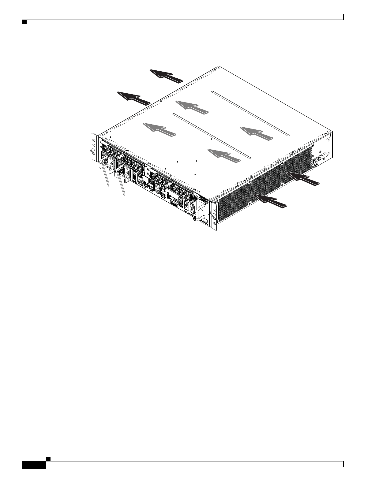
Follow these unpacking steps to unpack the Cisco ASR 9001 Router from its shipping container (see
Figure 2-1).
Step 1 Cut the packaging tape and open the cardboard shipping container.
Step 2 Remove the accessory box.
Step 3 Remove the packaging material (see Figure 2-1).
a. Remove the foam packaging material from the top of the router.
b. Remove cardboard caps from both sides.
c. Remove the router from the bag.
Step 4 Save the packaging materials in case the router needs repackaging or shipping.
2-2
Cisco ASR 9001 and Cisco ASR 9001-S Routers Hardware Installation Guide
OL-26701-02
Page 41

Chapter 2 Unpacking and Installing the Chassis
Figure 2-1 Unpacking the Cisco ASR 9001 Router from the Shipping Container
3
Unpacking the Cisco ASR 9001 Router
2
4
5
5
6
1
1 Cardboard packaging container 4 Bag containing router
2 Accessory box 5 Cardboard caps
3 Foam packaging material- top caps 6 Foam packaging material - bottom cap
332150
Positioning the Router
Use a safety hand truck to move the router to the location where it is being installed in a rack.
OL-26701-02
Cisco ASR 9001 and Cisco ASR 9001-S Routers Hardware Installation Guide
2-3
Page 42

Rack-Mounting the Router Chassis
Rack-Mounting the Router Chassis
The router chassis is installed in a front-mounted position, as shown in Figure 1-7 for the
Cisco ASR 9001 Router chassis.
In a front-mounted position, the chassis rack-mounting flanges are secured directly to the rack posts.
The PID of the rack mounting kit for Cisco ASR 9001 Router and Cisco ASR 9001-S Router is
ASR-9001-2P-KIT=.
Verifying Rack Dimensions
Before you install the chassis, measure the space between the vertical mounting flanges (rails) on your
equipment rack to verify that the rack conforms to the measurements shown in Figure 2-2.
Step 1 Mark and measure the distance between two holes on the left and right mounting rails.
The distance should measure 18.31 inches ± 0.06 inches (46.5 cm ± 0.15 cm).
Chapter 2 Unpacking and Installing the Chassis
Note Measure the distance for pairs of holes near the bottom, middle and top of the equipment rack
to ensure that the rack posts are parallel.
Step 2 Measure the space between the inner edges of the left front and right front mounting flanges on the
equipment rack.
The space must be at least 17.7 inches (45 cm) to accommodate the chassis, which is approximately
17.45 in. (44.32 cm) wide, and fits between the mounting posts on the rack.
Figure 2-2 Verifying Equipment Rack Dimensions
Mounting flanges
Minimum usable
aperture 17.7 inches
(45.0 cm)
Hole centerline
to hole centerline
18.31 inches ± 0.06 inches
(46.5 cm ± 0.15 cm)
247170
Installing the Chassis in a 2-Post Rack
Two people must lift the router chassis using the handles on the sides. To accommodate racks with
different hole patterns in their mounting flanges, the chassis rack-mounting flanges have three oblong
screw holes on each side.
Cisco ASR 9001 and Cisco ASR 9001-S Routers Hardware Installation Guide
2-4
OL-26701-02
Page 43

Chapter 2 Unpacking and Installing the Chassis
332151
1
1
This section describes how to install the chassis in a 2-post telco-style rack.
Figure 2-3 shows the orientation of the Cisco ASR 9001 Router chassis to the rack posts and
components used in the installation.
Figure 2-3 Installing the Cisco ASR 9001 Router Chassis in a 2-Post Rack
Rack-Mounting the Router Chassis
1 Three screws on each side (minimum two) to attach the router chassis to the
rack
Cisco ASR 9001 and Cisco ASR 9001-S Routers Hardware Installation Guide
OL-26701-02
2-5
Page 44

Rack-Mounting the Router Chassis
Use this procedure to install the chassis in the equipment rack:
Step 1 With two people’s aid, lift the chassis into the rack holding top and bottom of the chassis (see
Figure 2-4).
Figure 2-4 Correct Lifting Positions
Chapter 2 Unpacking and Installing the Chassis
Caution Do not grasp air inlet or exhaust when lifting the router chassis.
Step 2 Position the chassis until the rack-mounting flanges are flush against the mounting rails on the rack.
Step 3 Hold the chassis in position against the mounting rails while the second person finger-tightens a screw
to the rack rails on each side of the chassis.
Step 4 Finger-tighten two more screws to the rack rails on each side of the chassis. Space the screws evenly
between the top and bottom of the chassis.
Step 5 Attach the side brackets to the left and right side of the chassis by finger-tightening two screws through
each bracket into the chassis.
Step 6 Attach the side bracket front flanges to the rack by finger-tightening two screws through each bracket
flange into the front mounting rails of the rack.
Step 7 Fully tighten both the screws on the chassis mounting flanges on each side to secure the chassis to the
rack rails.
Step 8 Fully tighten the two screws on each side bracket to secure the brackets to the chassis.
Step 9 Fully tighten the two screws on each side bracket flange to secure the brackets to the rack rails.
2-6
Cisco ASR 9001 and Cisco ASR 9001-S Routers Hardware Installation Guide
OL-26701-02
Page 45

Chapter 2 Unpacking and Installing the Chassis
Installing the Chassis in a 4-post Rack
To mount the Cisco ASR 9001 Router chassis in a 4-post open rack, two side brackets must be attached
to the chassis and the rear posts (see Figure 2-5).
Figure 2-5 Installing the Cisco ASR 9001 Router Chassis in a 4-Post Rack
Supplemental Bonding and Grounding Connections
Supplemental Bonding and Grounding Connections
Before you power on the router for the first time, we recommend that you connect the central office
ground system or Network Equipment Building System (NEBS) to the threaded supplemental bonding
and grounding receptacles on the router. For more information on supplemental bonding and grounding
cable requirements, see the “NEBS Supplemental Unit Bonding and Grounding Guidelines” section on
page 1-20.
Cisco ASR 9001 and Cisco ASR 9001-S Routers Hardware Installation Guide
OL-26701-02
332153
2-7
Page 46

Supplemental Bonding and Grounding Connections
Use this procedure to attach a grounding cable lug to the router:
Step 1 Insert the grounding screws through the locking washers, and into the threaded grounding receptacle on
the Cisco ASR 9001 Router chassis as shown in Figure 2-6.
Step 2 Tighten the grounding screws securely to the receptacles.
Step 3 Prepare the other end of the grounding wire, and connect it to the appropriate grounding point at your
site to ensure an adequate earth ground.
Figure 2-6 NEBS Bonding and Grounding for the Cisco ASR 9001 Router
Chapter 2 Unpacking and Installing the Chassis
2-8
332154
Cisco ASR 9001 and Cisco ASR 9001-S Routers Hardware Installation Guide
OL-26701-02
Page 47

CHAP T ER
3
Installing Modules and Cables in the Chassis
This chapter contains the procedures for installing cards and modules into the chassis, after it has been
installed in a rack. It also describes how to connect cables to the ports and RP.
The installation is presented in these sections:
• Fixed 4x10-Gigabit Ethernet Ports, page 3-1
• Modular Port Adapters, page 3-2
• Installing and Removing Modular Port Adapters, page 3-5
• Installing and Removing SFP Modules, page 3-11
• Installing and Removing XFP Modules, page 3-11
• Cable Management, page 3-12
• Connecting Route Processor Cables, page 3-16
• Connecting Power to the Router, page 3-18
• Powering on the Router, page 3-21
Fixed 4x10-Gigabit Ethernet Ports
The Cisco ASR 9001 Router has four integrated 10 GE small form-factor pluggable (SFP+) ports that
operate at a rate of 10 Gbps.
Each fixed SFP+ port has an adjacent Link LED visible on the front panel. The Link LED indicates the
status of the associated SFP+ port.
Note In Cisco ASR 9001-S Router, two 10 GE fixed SFP+ ports (SFP+2 and SFP+3) are disabled by default,
and can be enabled by a license upgrade.
Figure 3-1 shows the front panel of the chassis and connectors of the fixed 4x10-Gigabit Ethernet ports.
Cisco ASR 9001 and Cisco ASR 9001-S Routers Hardware Installation Guide
OL-26701-02
3-1
Page 48

Modular Port Adapters
1 3 4 5 6 687
92
Figure 3-1 .4x10-Gigabit Ethernet SFP+ Ports
9 Fixed 10 GE SFP+ ports
Modular Port Adapters
Chapter 3 Installing Modules and Cables in the Chassis
The Cisco ASR 9001 Router has two ethernet pluggable ports that support these Modular Port Adapters
(MPAs):
• 20-Port GE MPA
• 4-Port 10-GE MPA
• 2-Port 10-GE MPA
Note In Cisco ASR 9001-S Router, one ethernet pluggable port (MPA1) is disabled by default, and can be
enabled by license upgrade.
20-Port Gigabit Ethernet Modular Port Adapter
The 20-Port Gigabit Ethernet modular port adapter provides 10 double-stacked SFP (20 total) cages that
support either fiber-optic or copper Gigabit Ethernet transceivers.
Each SFP cage on the Gigabit Ethernet modular port adapter has an adjacent Link LED visible on the
front panel. The Link LED indicates the status of the associated SFP port, as described in Table 4-4.
Refer to Figure 3-2 for an example of the 20-Port Gigabit Ethernet Modular Port Adapter.
3-2
Cisco ASR 9001 and Cisco ASR 9001-S Routers Hardware Installation Guide
OL-26701-02
Page 49

Chapter 3 Installing Modules and Cables in the Chassis
Figure 3-2 20-Port Gigabit Ethernet Modular Port Adapter
Modular Port Adapters
330784
Table 3-1 describes the 20-Port Gigabit Ethernet modular port adapter LEDs.
Table 3-1 20-Port Gigabit Ethernet Modular Port Adapter LEDs
LED Label Color State Meaning
A/L Off Off Port is not enabled.
Green On Port is enabled and the link is up. The MPA A/L LED will
blink green when there is traffic activity.
Amber On Port is enabled and the link is down.
STATUS Off Off Modular port adapter power is off.
Green On Modular port adapter is ready and operational.
Amber On Modular port adapter power is on and good, and modular
port adapter is being configured.
4-Port 10 Gigabit Ethernet Modular Port Adapter
The 4-Port 10 Gigabit Ethernet modular port adapter provides four cages for XFP Ethernet optical
interface modules that operate at a rate of 10 Gbps. The four XFP modules can be 10-Gigabit Ethernet
multimode or single mode connections.
Each XFP cage on the 4-Port 10 Gigabit Ethernet modular port adapter has an adjacent Link LED visible
on the front panel. The Link LED indicates the status of the associated XFP port, as described in
Table 4-4.
Refer to Figure 3-3 for an example of the 4-Port 10 Gigabit Ethernet modular port adapter.
OL-26701-02
Cisco ASR 9001 and Cisco ASR 9001-S Routers Hardware Installation Guide
3-3
Page 50

Modular Port Adapters
330784
STATUS
A9K-MPA-4X10GE
A9K-MPA-4X10GE
0
3
2
1
Chapter 3 Installing Modules and Cables in the Chassis
Figure 3-3 4-Port 10 Gigabit Ethernet Modular Port Adapter
Table 3-2 describes the 4-Port 10 Gigabit Ethernet modular port adapter LEDs.
Table 3-2 4-Port 10 Gigabit Ethernet Modular Port Adapter LEDs
LED Label Color State Meaning
A/L Off Off Port is not enabled.
Green On Port is enabled and the link is up. The MPA A/L LED will
Amber On Port is enabled and the link is down.
STATUS Off Off Modular port adapter power is off.
Green On Modular port adapter is ready and operational.
Amber On Modular port adapter power is on and good, and the
2-Port 10 Gigabit Ethernet Modular Port Adapter
The 2-Port 10 Gigabit Ethernet modular port adapter provides two cages for XFP Ethernet optical
interface modules that operate at a rate of 10 Gbps. The two XFP modules can be 10-Gigabit Ethernet
multimode or single mode connections.
Each XFP cage on the 2-Port 10 Gigabit Ethernet modular port adapter has an adjacent Link LED visible
on the front panel. The Link LED indicates the status of the associated XFP port, as described in
Table 4-4.
Refer to Figure 3-4 for an example of the 2-Port 10 Gigabit Ethernet modular port adapter.
blink green when there is traffic activity.
modular port adapter is being configured.
3-4
Cisco ASR 9001 and Cisco ASR 9001-S Routers Hardware Installation Guide
OL-26701-02
Page 51

Chapter 3 Installing Modules and Cables in the Chassis
330784
STATUS
A9K-MPA-2X10GE
A9K-MPA-2X10GE
0
Figure 3-4 2-Port 10 Gigabit Ethernet Modular Port Adapter
Installing and Removing Modular Port Adapters
Table 3-2 describes the 2-Port 10 Gigabit Ethernet modular port adapter LEDs.
Table 3-3 2-Port 10 Gigabit Ethernet Modular Port Adapter LEDs
LED Label Color State Meaning
A/L Off Off Port is not enabled.
Green On Port is enabled and the link is up. The MPA A/L LED will
blink green when there is traffic activity.
Amber On Port is enabled and the link is down.
STATUS Off Off Modular port adapter power is off.
Green On Modular port adapter is ready and operational.
Amber On Modular port adapter power is on and good, and the
modular port adapter is being configured.
Installing and Removing Modular Port Adapters
These sections describe how to install or remove modular port adapters (MPAs) on the
Cisco ASR 9001 Router.
• Handling Modular Port Adapters (MPAs), page 3-6
• Online Insertion and Removal, page 3-6
OL-26701-02
• Modular Port Adapter (MPA) Installation and Removal, page 3-7
• Optical Device Installation and Removal, page 3-8
Cisco ASR 9001 and Cisco ASR 9001-S Routers Hardware Installation Guide
3-5
Page 52

Installing and Removing Modular Port Adapters
H6420
Metal carrier
Printed circuit board
• Checking the Installation, page 3-8
Handling Modular Port Adapters (MPAs)
Each modular port adapter (MPA) circuit board is mounted on a metal carrier, and is sensitive to
electrostatic discharge (ESD) damage. Before you begin installation, refer to the Preparing to Install
Modular Line Cards (MLCs) or Modular Port Adapters (MPAs) section of the Cisco ASR 9000 Series
Aggregation Services Router Ethernet Line Card Installation Guide for a list of parts and tools required
for installation.
Caution Always handle the modular port adapter (MPA) by the carrier edges and handle; never touch the modular
port adapter (MPA) components or connector pins. (See Figure 3-5.)
When a bay is not in use, a blank ASR 9000 MPA Slot Filler (A9K-MPA-FILR) must fill the empty bay
to allow the router or switch to conform to electromagnetic interference (EMI) emissions requirements
and to allow proper airflow across the installed modules. If you plan to install a modular port adapter
(MPA) in a bay that is not in use, you must first remove the blank.
Chapter 3 Installing Modules and Cables in the Chassis
Figure 3-5 Handling a Modular Port Adapter (MPA)
Online Insertion and Removal
Cisco ASR 9001 Router modular port adapters (MPAs) support online insertion and removal (OIR).
Modular port adapters (MPAs) support three types of OIR:
• Soft OIR
Soft OIR uses the IOS XR hw-module subslot 0/0/1 reload, hw-module subslot 0/0/1 shutdown,
and no hw-module subslot 0/0/1 shutdown commands to complete online insertion and removal.
Refer to the Hardware Redundancy and Node Administration Commands on the Cisco ASR 9000
Series Router chapter of the Cisco ASR 9000 Series Aggregation Services Router System
Management Command Reference online for command syntax.
• Managed OIR
A managed online insertion and removal of Modular port adapters (MPAs) is comprised of these
steps:
Cisco ASR 9001 and Cisco ASR 9001-S Routers Hardware Installation Guide
3-6
1. Shut down the MPA with the hw-module subslot 0/0/1 shutdown command.
2. Confirm that the LEDs have gone from green to off.
OL-26701-02
Page 53

Chapter 3 Installing Modules and Cables in the Chassis
3. Execute the do show plat command to verify that the MPA to be removed is in the disabled
state.
4. Physically remove the MPA to be replaced.
5. Physically insert the replacement MPA
6. Return the MPA to the up state with the no hw-module subslot 0/0/1 shutdown command.
• Hard OIR
Hard OIR is the physical online insertion and removal of Modular port adapters (MPAs) without
software commands. Four types of hard OIR are supported:
If the bay is empty when the Cisco ASR 9001 Router modular line card (MLC) boots you can do the
following:
–
Insert a 20 GE MPA
–
Remove and then insert a replacement 20 GE MPA
If the MLC boots with a 20 GE MPA in the bay you can remove and then insert a replacement 20
GE MPA
If the MLC boots with a 4 10-GE MPA in the bay you can remove and then insert a replacement 4
10-GE MPA
Installing and Removing Modular Port Adapters
If the MLC boots with a 2 10-GE MPA in the bay you can remove and then insert a replacement 2
10-GE MPA
Note Only replacement with same types of MPA is supported by Managed OIR and Hard OIR. An
empty bay during the Cisco ASR 9001 Router modular line card (MLC) bootup defaults to
20 GE MPA mode.
Modular Port Adapter (MPA) Installation and Removal
This section provides step-by-step instructions for removing and installing a modular port adapter
(MPA).
Warning
Step 1 To insert the modular port adapter (MPA), locate the guide rails that hold the modular port adapter
Step 2 Carefully slide the modular port adapter (MPA) all the way until it is firmly seated in the modular port
When performing these procedures, wear a grounding wrist strap to avoid ESD damage to the modular
port adapter (MPA). Some platforms have an ESD connector for attaching the wrist strap. Do not
directly touch the midplane or backplane with your hand or any metal tool, or you could shock
yourself.
To remove and install a modular port adapter (MPA), perform these steps:
(MPA) in place. They are at the top-left and top-right of the modular port adapter (MPA) slot and are
recessed about an inch.
adapter (MPA) interface connector.
OL-26701-02
Cisco ASR 9001 and Cisco ASR 9001-S Routers Hardware Installation Guide
3-7
Page 54

Installing and Removing Modular Port Adapters
Note The modular port adapter (MPA) will slide easily into the slot if it is properly aligned on the
tracks. If the modular port adapter (MPA) does not slide easily, do NOT force it. Remove the
modular port adapter (MPA) and reposition it, paying close attention to engaging it on the tracks.
Step 3 After the modular port adapter (MPA) is properly seated, use a number 2 Philips screwdriver to tighten
the jackscrew on the modular port adapter (MPA).
Note Avoid over torquing the modular port adapter (MPA) jackscrew when installing the modular port
adapter (MPA).
Step 4 To remove the modular port adapter (MPA), use a number 2 Philips screwdriver to loosen the lock screw
on the modular port adapter (MPA).
Step 5 Grasp the modular port adapter (MPA) and pull the modular port adapter (MPA). (You have already
disconnected the cables from the modular port adapter (MPA)).
Chapter 3 Installing Modules and Cables in the Chassis
Optical Device Installation and Removal
Any contamination of the fiber connection can cause failure of the component or failure of the whole
system. A particle that partially or completely blocks the core generates strong back reflections, which
can cause instability in the laser system. Inspection, cleaning, and reinspection are critical steps to take
before making fiber-optic connections.
Cleaning Optical Devices
Refer to the Inspection and Cleaning Procedures for Fiber-Optic Connections document for information
on cleaning optical devices.
Checking the Installation
This section describes the procedures you can use to verify the modular port adapter (MPA) installation,
and includes information on these topics:
• Verifying the Installation, page 3-8
• Using show Commands to Verify Modular Port Adapter (MPA) Status, page 3-9
• Using show Commands to Display Modular Port Adapter (MPA) Information, page 3-10
• Using the ping Command to Verify Network Connectivity, page 3-10
Verifying the Installation
This section describes how to verify the modular port adapter (MPA) installation by observing the
modular port adapter (MPA) LED states.
Cisco ASR 9001 and Cisco ASR 9001-S Routers Hardware Installation Guide
3-8
OL-26701-02
Page 55

Chapter 3 Installing Modules and Cables in the Chassis
When the system has reinitialized all interfaces, the modular port adapter (MPA) STATUS LEDs should
be on (green). The port LEDs (C/A and A/L) may be on (green), depending on your connections and
configuration.
Use this procedure to verify that a modular port adapter (MPA) is installed correctly:
Step 1 Observe the console display messages and verify that the system discovers the modular line card (MLC),
while the system reinitializes each interface, thus:
• As a modular port adapter (MPA) is initialized, the STATUS LED will first be amber, indicating that
power is on. When the modular port adapter card (MPA) is active, the STATUS LED will illuminate
green.
Step 2 When the modular port adapter (MPA) STATUS LEDs are green, all associated interfaces are
configurable.
• If a modular port adapter (MPA) is replaced with a module of the same type (as in an OIR or
hardware swap), the previous configuration is reinstated when the modular port adapter (MPA)
becomes active.
• If a modular port adapter (MPA) has not been previously installed in the same slot or subslot, then
the configuration for all associated interfaces is empty.
Installing and Removing Modular Port Adapters
Note New interfaces are not made available until you configure them.
Step 3 If the modular port adapters (MPAs) do not become active within three minutes, refer to the system
console messages. If there is no indication that a field-programmable device (FPD) upgrade is underway,
see Troubleshooting the Installation.
Using show Commands to Verify Modular Port Adapter (MPA) Status
This procedure uses show commands to verify that the new modular port adapters (MPAs) are configured
and operating correctly.
Step 1 Use the show running-config command to display the system configuration. Verify that the
configuration includes the new modular port adapter (MPA) interfaces.
Step 2 Use the show diag command to display information about the installed modular line cards (MLCs).
Step 3 Use the show hw-module fpd location <rack/slot/subslot> command to verify the FPD version
information of the modular port adapters (MPAs) installed in the system.
Note If a modular port adapter (MPA) does not meet the minimum version required, the FPD may need
to be updated. Refer to Cisco ASR 9000 Series Aggregation Services Router System Management
Configuration Guide for instructions. If the update fails, the failing module is powered down and
an error message displays on the system console.
OL-26701-02
Step 4 Use the show platform command to check the state of all boards in the chassis, including the modular
line card (MLC) and the modular port adapters (MPAs).
The modular port adapter (MPA) state should be “OK” and the modular line card (MLC) card state
should be “IOS XR RUN” in the show platform command output.
Cisco ASR 9001 and Cisco ASR 9001-S Routers Hardware Installation Guide
3-9
Page 56

Chapter 3 Installing Modules and Cables in the Chassis
Installing and Removing Modular Port Adapters
Step 5 Use the show version command to obtain software version information for the installed modular line
cards (MLCs) as well as interfaces available.
Using show Commands to Display Modular Port Adapter (MPA) Information
Table 3-4 describes the show commands you can use to display modular port adapter (MPA)
information.
Table 3-4 show Commands to Display Modular Port Adapter (MPA) Information
Command Type of Information Provided
show running-config Router’s running configuration and interfaces available in the
system.
show platform Router’s installed linecard and modular port adapter (MPA) type,
slot, and state information.
show diag Modular port adapter (MPA) type in that slot, number of ports,
hardware revision, part number, and EEPROM contents.
show hw-module fpd location
<rack/slot/subslot>
show version Cisco IOS XR software version, names and sources of configuration
FPD version information of modular port adapters (MPAs) in the
system.
files, and boot images.
Table 3-5 show Commands to Display Modular Port Adapter (MPA) Information
Command Type of Information Provided Example
show controllers type
rack/slot/subslot/port
show interfaces type
rack/slot/subslot/port
Network link status, register contents, and
controller chip errors.
Line status and data link protocol status for a
particular modular port adapter (MPA) port.
show controllers GigabitEthernet
0/0/1/1
show interfaces GigabitEthernet
0/0/1/1
Statistics about data traffic sent and received by
the port.
show diag rack/slot/subslot/ Modular port adapter (MPA) type in that slot,
show diag 0/0/1
number of ports, hardware revision, part number,
and EEPROM contents.
show version Cisco IOS XR software version and boot images. show version
Using the ping Command to Verify Network Connectivity
The ping command allows you to verify whether a modular port adapter (MPA) port is functioning
properly and to check the path between a specific port and connected devices at various locations on the
network. After you verify that the system and the modular line card (MLC) have booted successfully and
are operational, you can use this command to verify the status of the modular port adapter (MPA) ports.
Refer to Cisco ASR 9000 Series Aggregation Services Router Getting Started Guide and Cisco ASR 9000
Series Aggregation Services Router Interface and Hardware Component Configuration Guide for more
information on bringing up and configuring the Cisco ASR 9000 Series Router and the Cisco ASR 9000
A9K-MOD80G-H.
3-10
Cisco ASR 9001 and Cisco ASR 9001-S Routers Hardware Installation Guide
OL-26701-02
Page 57

Chapter 3 Installing Modules and Cables in the Chassis
The ping command sends an echo request out to a remote device at an IP address that you specify. After
sending a series of signals, the command waits a specified time for the remote device to echo the signals.
Each returned signal is displayed as an exclamation point (!) on the console terminal; each signal that is
not returned before the specified timeout is displayed as a period (.). A series of exclamation points
(!!!!!) indicates a good connection; a series of periods (.....) or the messages [timed out] or [failed]
indicate that the connection failed.
This is an example of a successful ping command to a remote server with the IP address 10.1.1.60:
Router# ping 10.1.1.60
Type escape sequence to abort.
Sending 5, 100-byte ICMP Echoes to 10.1.1.60, timeout is 2 seconds:
!!!!!
Success rate is 100 percent (5/5), round-trip min/avg/max = 1/15/64 ms
Router#
If the connection fails, verify that you have the correct IP address for the destination device and that the
destination device is active (powered on), and then repeat the ping command.
Installing and Removing SFP Modules
Installing and Removing SFP Modules
Refer to the Installing and Removing SFP Modules section on the Installing Line Cards in the Cisco ASR
9000 Series Router chapter of the Cisco ASR 9000 Series Aggregation Services Router Ethernet Line
Card Installation Guide.
Installing and Removing XFP Modules
Refer to the Installing and Removing XFP Modules section on the Installing Line Cards in the Cisco ASR
9000 Series Router chapter of the Cisco ASR 9000 Series Aggregation Services Router Ethernet Line
Card Installation Guide.
OL-26701-02
Cisco ASR 9001 and Cisco ASR 9001-S Routers Hardware Installation Guide
3-11
Page 58

Cable Management
332700
Cable Management
Cisco ASR 9001 Router includes a cable-management system that organizes the interface cables
entering and exiting the router, keeping them out of the way, and free of sharp bends.
Caution Excessive bending of interface cables can damage the cables.
The cable-management system consists of thse separate components:
• A cable-management tray
• A cable-management bracket
Cable Management Tray
A cable-management tray is mounted at the bottom of the Cisco ASR 9001 Router chassis for routing
interface cables to the RP. Figure 3-6 shows a typical cable routing through the cable-management tray.
Chapter 3 Installing Modules and Cables in the Chassis
Figure 3-6 Example Cable Routing through the Cisco ASR 9001 Router Cable Management Tray
Installing a Cable Management Tray
To install a cable-management tray, follow these steps:
Step 1 Attach an ESD-preventive wrist or ankle strap and follow its instructions for use.
Step 2 Position the cable-management tray at the bottom of the chassis front panel.
Cisco ASR 9001 and Cisco ASR 9001-S Routers Hardware Installation Guide
3-12
OL-26701-02
Page 59

Chapter 3 Installing Modules and Cables in the Chassis
1
332147
Figure 3-7 Cable-Management Tray Installation and Removal
Cable Management
1 Cable-Management Tray
Step 3
Step 4 Connect all the cables to the intended ports and pass them throught the cable management tray in an
Insert and tighten the captive screw(s) to secure the tray. (see Figure 3-7).
organized manner.
Removing a Cable-Management Tray
To remove a cable-management tray, follow these steps (see Figure 3-7):
Step 1 Attach an ESD-preventive wrist or ankle strap and follow its instructions for use.
Step 2 Note the current interface cable connections to the ports on the RP.
Step 3 Starting with the interface cable for the bottom port on the RP, disconnect the cable from the RP
interface.
Step 4 Repeat Step 3 for all remaining interface cables, proceeding from the bottom ports upward, then proceed
to Step 5.
Step 5 Loosen the captive installation screw on the cable-management tray and remove the tray from the chassis
(see Figure 3-7).
OL-26701-02
Cisco ASR 9001 and Cisco ASR 9001-S Routers Hardware Installation Guide
3-13
Page 60

Cable Management
Cable Management Bracket
The Cisco ASR 9001 Router provides a cable management bracket at the middle of the router chassis.
Figure 3-8 shows a typical cable routing for the Cisco ASR 9001 Router.
Figure 3-8 Example Cable Routing through Cisco ASR 9001 Router Cable Management Brackets
Chapter 3 Installing Modules and Cables in the Chassis
Note When shipped, the cable-management bracket is not attached to the router chassis. You must attach the
cable-management bracket to the chassis before you insert the cables into the line card ports.
Caution Do not use the cable-management bracket as a handle to pull out or push in the line card. The
cable-management bracket is designed to hold the interface cables and may break if you use the bracket
to push, pull, or carry the line card after it is removed from the router.
Installing a Cable Management Bracket
To install a cable-management bracket, follow these steps:
Step 1 Attach an ESD-preventive wrist or ankle strap and follow its instructions for use.
Step 2 Position the cable-management bracket over the front of the chassis front panel.
332699
3-14
Cisco ASR 9001 and Cisco ASR 9001-S Routers Hardware Installation Guide
OL-26701-02
Page 61

Chapter 3 Installing Modules and Cables in the Chassis
1
Figure 3-9 Cable-Management Bracket Installation and Removal
Cable Management
1 Cable-Management Bracket
Step 3
Step 4 Connect all the cables to the intended ports and pass them throught the cable management bracket in an
Insert and tighten the captive screw(s) to secure the bracket. (see Figure 3-9).
organized manner.
Removing a Cable-Management Bracket
To remove a cable-management bracket, follow these steps (see Figure 3-9):
Step 1 Attach an ESD-preventive wrist or ankle strap and follow its instructions for use.
Step 2 Note the current interface cable connections to the ports on the RP.
Step 3 Starting with the interface cable for the bottom port on the RP, disconnect the cable from the RP
interface.
Step 4 Repeat Step 3 for all remaining interface cables, proceeding from the bottom ports upward, then proceed
to Step 5.
Step 5 Loosen the captive installation screw on the cable-management bracket and remove the bracket from the
chassis (see Figure 3-9).
OL-26701-02
Cisco ASR 9001 and Cisco ASR 9001-S Routers Hardware Installation Guide
3-15
Page 62

Connecting Route Processor Cables
1
3
2
4
Connecting Route Processor Cables
This section describes how to connect cables to the console, auxiliary, and Ethernet ports on the RP. The
console and auxiliary ports are both asynchronous serial ports; any devices connected to these ports must
be capable of asynchronous transmission. Most modems are asynchronous devices.
Figure 3-10 shows an example of an RP with data terminal and modem connections called out.
Figure 3-10 RP Console and Auxiliary Port Connections
Chapter 3 Installing Modules and Cables in the Chassis
1 Console terminal 3 RJ-45 Ethernet cables
2 Modem 4 Console and Auxiliary port
Caution The ports labeled Ethernet, Console, and AUX are safety extra-low voltage (SELV) circuits. SELV
circuits should only be connected to other SELV circuits.
Note RP cables are not available from Cisco, but they are available from external commercial cable vendors.
Note To comply with the intra-building lightning surge requirements of Telecordia GR-1089-CORE, Issue II,
Revision 01, February 1999, you must use a shielded cable when connecting to the console, auxiliary,
and Ethernet ports. The shielded cable is terminated by shielded connectors on both ends, with the cable
shield material tied to both connectors.
3-16
Cisco ASR 9001 and Cisco ASR 9001-S Routers Hardware Installation Guide
OL-26701-02
Page 63

Chapter 3 Installing Modules and Cables in the Chassis
Connecting to the RP Console Port
The system console port on the RP is an RJ-45 receptacle for connecting a data terminal to perform the
initial configuration of the router. The console port requires a straight-through RJ-45 cable.
See the “Cisco ASR 9001 Router Port Connection Guidelines” section on page 1-21 for additional
information about the console port.
See Figure 3-10 and use this procedure to connect a data terminal to the RP console port:
Step 1 Set your terminal to these operational values: 115200 bps, 8 data bits, no parity, 1 stop bits (115200
8N1).
Step 2 Power off the data terminal.
Step 3 Attach the terminal end of the cable to the interface port on the data terminal.
Step 4 Attach the other end of the cable to the RP console port.
Step 5 Power on the data terminal.
Connecting Route Processor Cables
Connecting to the RP Auxiliary Port
The auxiliary port on the RP is a RJ-45 receptacle for connecting a modem or other data communication
equipment (DCE) device (such as another router) to the RP. The asynchronous auxiliary port supports
hardware flow control and modem control.
See the “Cisco ASR 9001 Router Port Connection Guidelines” section on page 1-21 for additional
information about the auxiliary port.
See Figure 3-10 and use this procedure to connect an asynchronous serial device to the RP auxiliary port:
Step 1 Power off the asynchronous serial device.
Step 2 Attach the device end of the cable to the interface port on the asynchronous serial device.
Step 3 Attach the other end of the cable to the RP auxiliary port.
Step 4 Power on the asynchronous serial device.
Connecting to the RP Ethernet Management Ports
To connect cables to the RP management ports, attach Category 5 UTP cables directly to the
MGT LAN 0 and MGT LAN 1 RJ-45 receptacles on the RP.
See the “Management LAN Ports Connection Guidelines” section on page 1-24 for additional
information about the Ethernet management LAN ports.
OL-26701-02
Note RJ-45 cables are not available from Cisco Systems; they are available from external commercial cable
vendors. Use cables that comply with EIA/TIA-568 standards.
Cisco ASR 9001 and Cisco ASR 9001-S Routers Hardware Installation Guide
3-17
Page 64

Connecting Power to the Router
Caution Ethernet management ports are primarily used as Telnet ports into the Cisco ASR 9001, and for booting
or accessing Cisco software images over a network to which an Ethernet port is directly connected. We
strongly caution you to consider the security implications of enabling routing functions on these ports.
Note The Ethernet interfaces on the RP are end-station devices only, not repeaters.
Use this procedure to connect an Ethernet cable to the RP RJ-45 Ethernet receptacle:
Step 1 Plug the cable directly into the RJ-45 receptacle.
Step 2 Connect the network end of your RJ-45 cable to a switch, hub, repeater, or other external equipment.
Connecting Power to the Router
Chapter 3 Installing Modules and Cables in the Chassis
Use one of these procedures to connect power to your router.
• Connecting Power to an AC-Powered Router, page 3-18
• Connecting Power to a DC-Powered Router, page 3-20
Caution A router must be operated with all its power modules installed at all times for electromagnetic
compatibility (EMC).
Connecting Power to an AC-Powered Router
Use this procedure to connect the AC power cords to the router.
Note Connect each AC power supply to a dedicated power source (branch circuit). Each AC-input
power supply operates at a nominal input level of 100 to 240 VAC and requires at least a 15 A
service for use in North America and Japan, or a 10 A service for international use. For more
information on AC power input levels, see the “Power Connection Guidelines” section on
page 1-12.
Step 1 Check that the power switch at the front of the chassis is set to the OFF position.
Step 2 Check that the circuit breaker assigned to the AC power source you are connecting is set to OFF.
Step 3 Connect the permanent ground connection (central office grounding system) to the NEBS grounding
location on the router chassis.
3-18
Note To ensure that power remains off while you are performing this procedure, turn the circuit breaker switch
in the off (0) position until you are ready to turn it on.
Cisco ASR 9001 and Cisco ASR 9001-S Routers Hardware Installation Guide
OL-26701-02
Page 65

Chapter 3 Installing Modules and Cables in the Chassis
332894
Step 4 Plug the AC power cord into the receptacle at the front of the chassis (see Figure 3-11).
Step 5 Close the cable wrap to secure the AC power cord plug to the power module receptacle.
Figure 3-11 Typical AC Power Connections
Connecting Power to the Router
Step 6
Plug the other end of the AC power cord into the AC source receptacle.
Step 7 Proceed to the “Powering on the Router” section on page 3-21.
OL-26701-02
Cisco ASR 9001 and Cisco ASR 9001-S Routers Hardware Installation Guide
3-19
Page 66

Connecting Power to the Router
Connecting Power to a DC-Powered Router
This section contains the procedures to connect the DC source power cables to a DC-powered router.
The color coding of source DC power cable leads depends on the color coding of the site DC power
source. Because there is no color code standard for source DC wiring, you must be sure that power
source cables are connected to the power module with the proper positive (+) and negative (–) polarity:
• In some cases, the source DC cable leads might have a positive (+) or a negative (–) label. This is a
relatively safe indication of the polarity, but you must verify the polarity by measuring the voltage
between the DC cable leads. Be sure that the positive (+) and negative (–) cable leads match the
positive (+) and negative (–) labels on the power module when making the measurement.
• Green (or green and yellow) cable typically indicates that it is a ground cable.
Caution DC power modules contain circuitry to trip the breaker on the power module if the power module detects
a reverse polarity condition. No damage would occur from reverse polarity, but you should correct a
reverse-polarity condition immediately.
Chapter 3 Installing Modules and Cables in the Chassis
Note The length of the cables depends on the location of your router in relation to the source of DC power.
These cables are not available from Cisco Systems. They are available from external commercial cable
vendors. For more information on site power and source DC cable requirements, see the “Power
Connection Guidelines” section on page 1-12.
Note To ensure that power remains off while you are performing this procedure, tape the DC circuit breaker
switch in the off (0) position.
Use this procedure to connect the DC source power cables to a DC power module:
Step 1 Verify that the power switch is set to the OFF position.
Step 2 Connect the DC power cables in the following order (see Figure 3-12):
a. Ground cables first.
b. Positive cables next.
c. Negative cable last.
Step 3 Repeat Step 2 for the other power modules installed in the chassis.
Warning
To prevent injury and damage to the equipment, always attach the ground and source DC power cable
to power module terminals in the following order: (1) ground to ground, (2) positive (+) to positive (+),
(3) negative (–) to negative (–).
3-20
Cisco ASR 9001 and Cisco ASR 9001-S Routers Hardware Installation Guide
OL-26701-02
Page 67

Chapter 3 Installing Modules and Cables in the Chassis
Figure 3-12 Typical Power Connections for a Single DC Power Module
Powering on the Router
Step 4
Proceed to the “Powering on the Router” section on page 3-21.
Powering on the Router
Use this procedure to turn on power to either an AC-powered or DC-powered router:
Step 1 Power on the circuit breaker to your power sources.
Step 2 Verify that the Power Input LED on each power module is lit.
Step 3 Set the power switch to the ON position.
Step 4 Verify that the Green Power LED on each power module is lit.
331933
OL-26701-02
Cisco ASR 9001 and Cisco ASR 9001-S Routers Hardware Installation Guide
3-21
Page 68

Powering on the Router
Chapter 3 Installing Modules and Cables in the Chassis
3-22
Cisco ASR 9001 and Cisco ASR 9001-S Routers Hardware Installation Guide
OL-26701-02
Page 69

CHAP T ER
4
Troubleshooting the Installation
This chapter contains general troubleshooting information to help isolate the cause of any difficulties
you might encounter during the installation and initial startup of the system.
Although an over-temperature condition is unlikely at initial startup, environmental monitoring
functions are included in this chapter because these too monitor internal voltages.
Troubleshooting the installation is presented in these sections:
• Troubleshooting Overview, page 4-1
• Troubleshooting the Power Subsystem, page 4-3
• Troubleshooting the Route Processor Subsystem, page 4-9
• Troubleshooting the Line Card, page 4-12
• Troubleshooting the Cooling Subsystem, page 4-18
Troubleshooting Overview
This section describes the methods used in troubleshooting the router. The troubleshooting methods are
organized according to the major subsystems in the router.
If you are unable to solve a problem on your own, you can contact a Cisco customer service
representative for assistance. When you call, have this information ready:
• Date you received the router and the chassis serial number (located on a label on the back of the
chassis).
• Installed line card and Cisco software release number:
–
Use the show version command to determine the Cisco software release number.
• Brief description of the symptoms and steps you have taken to isolate and solve the issue.
• Maintenance agreement or warranty information.
Troubleshooting Using a Subsystem Approach
To solve a system problem, try to isolate the problem to a specific subsystem. Compare the current router
behavior with the expected router behavior. Because a startup issue is usually attributable to one
component, it is most efficient to examine each subsystem, rather than trying to troubleshoot each router
component.
OL-26701-02
Cisco ASR 9001 and Cisco ASR 9001-S Routers Hardware Installation Guide
4-1
Page 70

Troubleshooting Overview
For troubleshooting purposes in this chapter, the router consists of these subsystems:
• Power subsystem—Router chassis is shipped with up to two AC-input or DC-input power supply
modules installed in the Cisco ASR 9001 Router chassis.
• Chassis backplane power distribution—System transfers +12 VDC power from the power modules
to the chassis backplane and distributes it to all the cards through the backplane connectors. The fan
tray receives power from the chassis backplane and communicate to the RP CAN Bus controller.
• Processor subsystem—Includes the active Route Processor (RP) card with line card. The RP is
equipped with onboard processors. The RP downloads a copy of the Cisco software image to the line
card processor.
• Cooling subsystem—Consists of one fantray with 14 fans, which circulate cooling air through the
chassis.
Normal Router Startup Sequence
You can generally determine when and where the router failed during the startup sequence by checking
the status LEDs on the power modules and RP.
Chapter 4 Troubleshooting the Installation
In a normal router startup sequence, this sequence of events and conditions occur:
1. The fan in each power module receives power and begins drawing air through the power supply.
The power module input power and output power indicators are on.
2. The fans in the fan tray receive power and begin drawing air through the chassis.
The fan tray OK indicator is on.
3. As the power-on and boot process progresses for the RP, the status of the RP appears on the front
panel of the card.
Identifying Startup Issues
Table 4-1 shows the LED states on the power modules (AC or DC), RP, and the fan tray after a successful
system startup.
Table 4-1 LEDs at System Startup
Component Type of Indicator Display Contents/LED Status and Meaning
Line Card Status LED Green: The line card is enabled and ready for use.
AC Power
Modules
DC Power
Modules
Fan Tray Fan tray status LED Green (ON): Fan Tray OK.
Power status LEDs Green (ON): Input AC power OK.
Amber (OFF): No fault is present.
The correct power module voltages are present and no faults have been detected.
Power status LEDs Green (ON): Input DC power OK.
Amber (OFF): No fault is present.
The correct power module voltages are present and no faults have been detected.
The fan tray fans are operating correctly.
4-2
Cisco ASR 9001 and Cisco ASR 9001-S Routers Hardware Installation Guide
OL-26701-02
Page 71

Chapter 4 Troubleshooting the Installation
Troubleshooting the Power Subsystem
This section contains information to troubleshoot the power subsystems:
• Troubleshooting the AC-Input Power Subsystem, page 4-3
• Troubleshooting the DC-Input Power Subsystem, page 4-5
• Troubleshooting the Power Distribution System, page 4-8
Note For the RP card to communicate properly to a power module, input power to at least one of the two power
modules should be present.
Troubleshooting the AC-Input Power Subsystem
AC-input power modules are monitored for internal temperature, voltage, and current load by the RP. If
the router detects an extreme condition, it generates an alarm and logs the appropriate warning messages
on the console.
Figure 4-1 shows the status indicators for the power module. The indicator definitions are provided after
the figure.
Troubleshooting the Power Subsystem
OL-26701-02
Cisco ASR 9001 and Cisco ASR 9001-S Routers Hardware Installation Guide
4-3
Page 72

Troubleshooting the Power Subsystem
Figure 4-1 Power Module Status Indicators
Chapter 4 Troubleshooting the Installation
2
1 OK (Green) Power
LED
1
ON when the power supply is ON and OK
BLINKING when the input AC power voltage is present
332384
OFF when no input voltage is present
2 FAIL (Amber)
LED
ON when power supply failure occurs (due to over voltage, over current, over
temperature, and fan failure)
BLINKING when alarm condition or power supply warning events occur, where
the power supply continues to operate (due to high temperature, high power, or
slow fan)
OFF when no power supply failure has occurred
Use this procedure to troubleshoot the AC power module if it is not operating properly:
Step 1 Make sure the power module is seated properly by ejecting and reseating the power module. Verify that:
• Latch on the ejector lever is locked securely.
• Power switch on the front panel is set to the ON position.
Step 2 Make sure the router is powered on and that all power cords are connected properly. Verify that:
• Power cables are securely attached to their power module terminal studs.
• Power cords at the power source end are securely plugged into their own AC power outlets.
4-4
• Source AC circuit breaker is switched on.
Step 3 Check the power supply status LED indicators:
• OK (green) Power LED—Indicates that the input AC power is OK.
If the OK LED is blinking, AC power input is operating normally, and the source AC input voltage
of 100 to 240 VAC is within the nominal operating range.
Cisco ASR 9001 and Cisco ASR 9001-S Routers Hardware Installation Guide
OL-26701-02
Page 73

Chapter 4 Troubleshooting the Installation
• FAIL (amber) LED —Indicates the power supply failure, includes over voltage, over current, over
temperature and fan failure conditions.
If the FAIL LED is blinking, it indicates alarm condition or power supply warning events, while the
power supply continues to operate; this includes high temperature, high power, or slow fan
conditions. Make sure that each power cord is connected to a dedicated AC power source. Verify
that each AC power source is operating in the nominal range of 100 to 240 VAC and is supplying a
minimum service of 15 A, North America (or 10 A, international).
Troubleshooting the DC-Input Power Subsystem
DC-input power supplies are monitored for internal temperature, voltage, and current load by the RP. If
the router detects an extreme condition, it generates an alarm and logs the appropriate warning messages
on the console.
Figure 4-1 shows the status indicators for the power module. The indicator definitions are provided after
the figure.
Troubleshooting the Power Subsystem
Troubleshooting a DC Power Module
Use this procedure to troubleshoot a DC power module if it is not operating properly.
Step 1 Make sure the power module is seated properly by ejecting and reseating the power module. Verify that:
• Latch on the ejector lever is locked securely.
• Power switch on the front panel is set to the ON position.
Step 2 Make sure the router is powered on and that all power cords are connected properly. Verify that:
• Power cables are securely attached to their power module terminal studs.
• Power cables are securely attached at the DC source end.
• Source DC circuit breaker is switched on.
Step 3 Check the power supply status LED indicators:
• OK (green) Power LED—Indicates that the input DC power is OK.
If the OK LED is blinking, DC power input is operating normally, and the source DC input voltage
of –40 to –72 VDC is within the nominal operating range.
• FAIL (amber) LED —Indicates the power supply failure, includes over voltage, over current, over
temperature and fan failure conditions.
If the FAIL LED is blinking, it indicates alarm condition or power supply warning events, while the
power supply continues to operate; this includes high temperature, high power, or slow fan
conditions. Make sure that each power cable is connected to a dedicated DC power source. Verify
that each DC power source is operating in the nominal range of –40 to –72 VDC.
OL-26701-02
Cisco ASR 9001 and Cisco ASR 9001-S Routers Hardware Installation Guide
4-5
Page 74

Chapter 4 Troubleshooting the Installation
Troubleshooting the Power Subsystem
Additional Power Subsystem Troubleshooting Information
This section contains additional troubleshooting information to help you isolate the cause of a power
problem.
Hardware and Software Identification
The power modules have software IDs that differ from the hardware ID labels on the chassis. Table 4-2
is a table for converting power module hardware IDs to software IDs.
Table 4-2 Power Module Hardware and Software IDs
Hardware ID Software ID
PS0 M0 PM0
PS0 M1 PM1
Obtaining Temperature and Environmental Information
If both the RP and the fan tray are operating, all internal correct DC voltages are present.
Enter the show environment command at the router admin prompt to display temperature and voltage
information for each installed card, fan tray, and power module as shown in this example:
RP/0/RSP0/CPU0:router(admin)#show environment
Sat Apr 15 04:57:35.185 UTC
Temperature Information
---------------------------------------------
R/S/I Modules Sensor (deg C)
0/RSP0/*
host Inlet0 31.1
host Inlet1 30.3
host Hotspot0 45.8
host Hotspot1 38.3
host Hotspot2 45.5
host Hotspot3 46.0
0/0/*
ep0 Inlet0 33.1
ep0 Hotspot0 38.5
ep1 Inlet0 33.6
ep1 Hotspot0 37.5
host Hotspot0 43.5
host Hotspot1 37.8
host Hotspot2 45.7
host Hotspot3 41.6
host Hotspot4 45.9
host Inlet0 36.0
4-6
Voltage Information
---------------------------------------------
R/S/I Modules Sensor (mV) Margin
Cisco ASR 9001 and Cisco ASR 9001-S Routers Hardware Installation Guide
OL-26701-02
Page 75

Chapter 4 Troubleshooting the Installation
0/RSP0/*
host 5.0V 5000 n/a
host VP3P3_CAN 3299 n/a
host 0.75V 750 n/a
host 3.3V_RSP 3299 n/a
host 2.5V_RSP 2499 n/a
host 1.8V_RSP 1799 n/a
host 1.5V_RSP 1500 n/a
host 1.2V_RSP 1199 n/a
host 1.9V_LDO_RSP 1900 n/a
host 1.2V_TIMEX 1199 n/a
host 1.0V_IMIO_CORE 1000 n/a
host 1.8V_USB 1799 n/a
host 12.0V 12004 n/a
host 7.0V_RSP 7000 n/a
host 3.3V_OCXO_RSP 3301 n/a
host 1.0V_RSP 1000 n/a
0/0/*
ep0 IBV 7960 n/a
ep0 VP3P3 3319 n/a
ep0 VP1P2 1200 n/a
ep0 VP1P2_PHY 1193 n/a
ep0 VP3P3_AUX 3276 n/a
ep1 VP2P5 2499 n/a
ep1 VP3P3 3300 n/a
ep1 VP1P2 1200 n/a
ep1 VP1P8 1799 n/a
ep1 VP5P0 5000 n/a
ep1 VP0P9_HEXP0 899 n/a
ep1 VP0P9_LDO 900 n/a
ep1 VP1P2_LDO 1199 n/a
host 5.0V 5000 n/a
host VP3P3_CAN 3299 n/a
host 2.5V 2500 n/a
host 0.75V 749 n/a
host 2.5V_DB 2499 n/a
host 1.8V_DB 1799 n/a
host 7.0V 6998 n/a
host VP1P0_SAC_CORE 1000 n/a
host VP1P0_SAC_VDDA 1000 n/a
host VP1P0_SAC_VDDD 1000 n/a
host VP1P2_SAC_VDDT 1199 n/a
host VP1P8_SAC_VDDR 1799 n/a
host VP1P0_SKT1_CORE 1000 n/a
host VP1P0_SKT2_CORE 1000 n/a
host VP1P0_CPU_CORE 999 n/a
host VP1P2 1199 n/a
host VP1P5 1500 n/a
host VP3P3_DB 3300 n/a
host VP1P5_DB 1499 n/a
host 1.2V_BLWDO 1200 n/a
host 1.0V_BLWDO 1000 n/a
host 1.8V_LC 1799 n/a
host 1.0V_FPGA_CORE_LC 999 n/a
host 1.2V_LC 1199 n/a
host 1.2V_PHY_LDO 1200 n/a
host 0.9V_PHY_LDO 900 n/a
host 0.9V_PHY_CORE 899 n/a
host 1.0V_LC_MB 999 n/a
host 3.3V_LC 3300 n/a
Troubleshooting the Power Subsystem
OL-26701-02
Cisco ASR 9001 and Cisco ASR 9001-S Routers Hardware Installation Guide
4-7
Page 76

Troubleshooting the Power Subsystem
host 1.8V_ZAR_LDO 1799 n/a
host 3.3V_ZAR_LDO 3300 n/a
host 2.5V_SKT_SKM 2500 n/a
host 1.8V_LGTNG 1800 n/a
host 1.5V_NP4C_1 1500 n/a
host 1.5V_SKT 1500 n/a
host 1.05V_NP4C_CORE 1050 n/a
host 1.0V_SKT 1000 n/a
host 1.0V_SKM 999 n/a
host 1.0V_LGTNG_CORE 1000 n/a
host 0.9V_TCAM0_CORE 910 n/a
host 0.9V_TCAM1_CORE 909 n/a
host 3.3V_CLK_LDO 3299 n/a
host 2.5V_CLK_LDO 2499 n/a
host 1.2V_WL_LDO 1199 n/a
host 1.0V_WL_LDO 999 n/a
host 1.0V_PEX1 992 n/a
host 1.0V_PEX2 999 n/a
host 1.5V_NP4C2 1500 n/a
LED Information
---------------------------------------------
Chapter 4 Troubleshooting the Installation
R/S/I Modules LED Status
0/RSP0/*
host Critical-Alarm Off
host Major-Alarm Off
host Minor-Alarm Off
host ACO Off
host Fail Off
RP/0/RSP0/CPU0:ios#
Troubleshooting the Power Distribution System
The power distribution system consists of:
• AC or DC power modules that supply +12 VDC to the backplane.
• Chassis backplane that carries voltage to chassis components.
• DC-to-DC converters that convert +12 VDC from the backplane to the correct voltages required by
the line card.
Use this procedure to troubleshoot the power distribution system:
Step 1 Check each power module to make sure that:
• Power module is fully inserted and properly secured by its latch.
• Green LED is on.
4-8
• Amber LED is off.
If the power modules meet the above criteria, then the correct source power is present and within
tolerance, and output DC power is present. The power modules are functioning properly.
Step 2 Make sure the fan tray is operating:
• If the fan tray is functioning, then the +12 VDC from the chassis backplane to the fan tray is
functioning properly.
Cisco ASR 9001 and Cisco ASR 9001-S Routers Hardware Installation Guide
OL-26701-02
Page 77

Chapter 4 Troubleshooting the Installation
1 3 4 5 6 687
92
Troubleshooting the Route Processor Subsystem
• If the fan tray is still not operating, there could be a problem with either the fan tray or with the
+12 VDC distribution through backplane.
• Contact your Cisco representative if replacing the fan tray does not fix the problem.
Troubleshooting the Route Processor Subsystem
The router processor subsystem consists of the route processor located on the RP card. The RP and the
line card each has the same onboard CPU serving as the main processor. The Controller Area Network
(CAN) microcontroller processor monitors the environment and controls the onboard DC-to-DC
converters.
This section contains information to troubleshoot the route processor subsystem, including:
• Route Processor Overview, page 4-9
• Configuring and Troubleshooting Line Card Interfaces, page 4-13
Route Processor Overview
The CPU on the RP card provides chassis control and management, boot media functionality, telecom
timing and precision clock synchronization, communication to the line card through the backplane
Ethernet network, and power control through the CAN bus. In addition, the CPU on the RP card also
runs the routing protocols.
Figure 4-2 identifies the slots, ports, and LEDs on the RP card front panel.
Figure 4-2 Cisco ASR 9001 Router Chassis Front Panel
1 Service LAN and ToD ports 6 External USB port
2 10MHz and 1PPS indicators 7 Eight discrete LED indicators
3 SYNC (BITS/J.211) ports 8 CLUSTER ports
4 CONSOLE and AUX ports 9 Line Card SFP+ ports
5 Management LAN ports
Cisco ASR 9001 and Cisco ASR 9001-S Routers Hardware Installation Guide
OL-26701-02
4-9
Page 78

Chapter 4 Troubleshooting the Installation
Troubleshooting the Route Processor Subsystem
RP Front Panel Indicators
The RP card has eight discrete LED indicators for display of system information.
Table 4-3 lists the display definitions of the eight discrete LEDs on the RP front panel as well as the
normal LED states on the power modules (AC or DC) and the fan tray after a successful system startup.
Table 4-3 RP Discrete LED Display Definitions
Indicator (Label) LED Color Description
RSP FAIL Bi-color Red RSP in initializing or failed state.
Green RSP is up and running.
Off RSP is normal.
LC FAIL Bi-color Red LC in initializing or failed state.
Green LC is up and running.
Off LC is normal.
Critical Alarm
(CRIT)
Major Alarm (MAJ) Single color Red Major alarm LED. A major alarm has occurred.
Minor Alarm (MIN) Single color Amber Minor alarm LED. A minor alarm has occurred.
External USB 2.0
(EUSB)
Alarm Cutoff (ACO) Single color Amber Alarm Cutoff has been enabled. The ACO push button
Synchronization
(SYNC)
FAIL/OK
(Power Module)
Single color Red Critical Alarm LED. A critical alarm has occurred.
Off
(Default after reset)
Off
(Default after reset)
Off
(Default after reset)
Single color Green External USB is busy/active. The LED is driven by the
Off
(Default after reset)
Off
(Default after reset)
Bi-color Green Sync - Time core is synchronized to an external source
Amber Not used.
Off
(Default after reset)
Bi-color Green Refer Figure 4-1 for detailed description.
Amber Refer Figure 4-1 for detailed description.
No critical alarm has occurred.
No major alarm has occurred.
No minor alarm has occurred.
USB controller.
External USB is not busy/active.
was pressed after at least one alarm has occurred.
Alarm Cutoff is not enabled.
Note: ACO LED is not in use and will always be OFF.
(either GPS or IEEE1588).
Time core clock synchronization is either disabled OR
Time core is synchronized with external source
excluding GPS and IEEE1588
4-10
Cisco ASR 9001 and Cisco ASR 9001-S Routers Hardware Installation Guide
OL-26701-02
Page 79

Chapter 4 Troubleshooting the Installation
Table 4-3 RP Discrete LED Display Definitions (continued)
Indicator (Label) LED Color Description
STATUS
(Fan tray)
Bi-color Amber Fan tray power ON state.
Green Fan tray fully functional.
Red Fan failure condition.
Ethernet Ports and Status LEDs
The RP has two 8-pin media-dependent interface (MDI) RJ-45 Management LAN ports for 10 Mbps,
100 Mbps, and 1000Mbps Ethernet connections. These ports are labeled MGT LAN 0 and MGT LAN 1.
The transmission speed of the Ethernet port is not user-configurable. You set the speed through an
auto-sensing scheme on the RP, the speed is determined by the network to which the Ethernet port is
connected. However, even at an auto-sensed data transmission rate of 100 Mbps, the Ethernet port can
only provide a usable bandwidth of substantially less than 100 Mbps. You can expect a maximum usable
bandwidth of approximately 12 Mbps when using an Ethernet connection.
These LEDs on the front panel indicate traffic status and port selection (see Figure 4-3):
• LINK—Indicates link activity.
• ACT—Indicates which Ethernet port is selected (ETH 0 or ETH 1).
Troubleshooting the Route Processor Subsystem
Note Because both ports are supported on the RP card, MGT LAN 0 is always on. MGT LAN 0 lights
when it is selected.
Figure 4-3 Management LAN Port Activity LEDs
Auxiliary and Console Ports
The auxiliary and console ports on the RP are EIA/TIA-232 (also known as RS-232) asynchronous serial
ports connect external devices to monitor and manage the system:
• Auxiliary port—RJ45 interface that supports flow control and is often used to connect a modem, a
channel service unit (CSU), or other optional equipment for Telnet management.
• Console port—Receptacle (female) that provides a RJ45 interface for connecting a console terminal.
332427
OL-26701-02
Cisco ASR 9001 and Cisco ASR 9001-S Routers Hardware Installation Guide
4-11
Page 80

Troubleshooting the Line Card
Monitoring Critical, Major, and Minor Alarm Status
Alarms warn of:
• Overtemperature condition on a component in the card
• Fan failure in the fan tray
• Overcurrent condition in a power supply
• Out-of-tolerance voltage on the card
The alarm LEDs are controlled by the CAN microcontoller software, which sets the threshold levels for
triggering the different stages of alarms.
The RP card continuously polls the system for temperature, voltage, current, and fan speed values. If a
threshold value is exceeded, the RP sets the appropriate alarm severity level on the alarm card, which
lights the corresponding LED, and energizes the appropriate alarm display relays to activate any external
audible or visual alarms wired to the alarm display. The RP also logs a message about the threshold
violation on the system console.
Note If one or more of the alarm LEDs is on, check the system console for messages describing the alarm.
Chapter 4 Troubleshooting the Installation
Troubleshooting the Line Card
Initial Boot Process
During a typical line card boot process, thse events occur:
1. The line card receives power and begins executing initialization software.
2. The line card performs internal checks, and prepares to accept the Cisco IOS XR software from the
RP.
3. The RP loads the line card with its Cisco IOS XR software.
To verify that the line card is working properly:
Step 1 Check that the LC FAIL LED is ON (green) to verify that the card is operating normally.
Step 2 Check that the RSP FAIL LED for the port of interest is ON (green or blinking) to verify that the port is
active. If the RSP FAIL LED is not ON, verify that the associated interface is not shut down.
Step 3 If one of the conditions above is not met, see the “Advanced Line Card Troubleshooting” section on
page 4-17 to identify any possible problems.
Status LEDs
Cisco ASR 9001 and Cisco ASR 9001-S Routers Hardware Installation Guide
4-12
You can use the LC FAIL LED or the RSP FAIL LED on the RP card front panel to verify proper
operation or troubleshoot a failure (see Table 4-4 ).
OL-26701-02
Page 81

Chapter 4 Troubleshooting the Installation
Table 4-4 RSP FAIL and LC FAIL LEDs
RSP FAIL LED
Green Port state is up and a valid physical layer link is established.
Blinking Line activity is occurring. The LED blinks green-amber-green.
Red Port state is up, but there is a link loss or SFP/XFP failure.
Off Port is administratively shut down.
LC FAIL LED
Green Line card has booted properly, and is ready to pass or is passing traffic.
Red Line card has encountered a hardware error, and is not passing traffic.
Off Line card is powered off. The LED might turn off momentarily when switching
between the states described above, although the line card has not powered off.
Configuring and Troubleshooting Line Card Interfaces
Troubleshooting the Line Card
After the person who installed the hardware verifies that the line card is working properly by examining
the LEDs, the network administrator can configure the new interface. These sections provide
information on configuring and troubleshooting the line card:
• Configuration Parameters, page 4-13
• Line Card Interface Address, page 4-14
• Using Configuration Commands, page 4-14
• Basic Line Card Configuration, page 4-14
• Verifying the Transceiver Modules, page 4-15
• Advanced Line Card Troubleshooting, page 4-17
Configuration Parameters
Table 4-5 lists the default interface configuration parameters that are present when an interface is
enabled on a 10-Gigabit Ethernet line card. See Cisco IOS XR software documentation for complete
information about these parameters.
Table 4-5 Line Card Configuration Default Values
Parameter Configuration File Entry Default Value
Flow control flow-control egress on
MTU mtu 1514 bytes for normal frames
ingress off
OL-26701-02
1518 bytes for IEEE 802.1Q tagged frames
1522 bytes for Q-in-Q frames
MAC address mac address Hardware burned-in address (BIA)
Cisco ASR 9001 and Cisco ASR 9001-S Routers Hardware Installation Guide
4-13
Page 82

Troubleshooting the Line Card
Line Card Interface Address
A Cisco ASR 9001 Router identifies an interface address by its rack number, line card slot number,
instance number, and port number, in the format rack/slot/instance/port. The rack parameter is reserved
for multirack systems; so, the rack parameter is always 0 (zero) for the Cisco ASR 9001 Router.
The line card slot is numbered 0 with three subslots. The subslots on the line card are numbered 0, 1,
and 2. 0 and 1 are reserved for EP ports and 2 is for native ports on the line card. Even if the line card
contains only one port, you must use the rack/slot/instance/port notation.
Using Configuration Commands
The command line interface (CLI) for Cisco IOS XR software is divided into different command modes.
To configure a line card, you enter the correct mode and then enter the commands you need.
When you first log in, you are automatically in EXEC mode. Next, enter the configure command to
access configuration mode. Then, enter the interface command to enter interface configuration mode
and specify the interface. You are now in the command mode where you can configure the new interface.
Be prepared with the information you will need, such as the interface IP address.
Chapter 4 Troubleshooting the Installation
Basic Line Card Configuration
This procedure is for creating a basic configuration—enabling an interface and specifying IP routing.
You might also need to enter other configuration subcommands, depending on the requirements for your
system configuration.
This example shows one way to configure the basic parameters of a line card:
Step 1 Enter EXEC mode:
Username: username
Password: password
RP/0/RSP0/CPU0:router#
Step 2 Check the status of each port by entering the show interface command:
RP/0/RSP0/CPU0:router# show interface
Step 3 Enter global configuration mode and specify that the console terminal will be the source of the
configuration commands:
RP/0/RSP0/CPU0:router# configure terminal
Step 4 At the prompt, specify the new interface to configure by entering the interface command, followed by
the type (for example, gigabitethernet or tengige) and rack/slot/instance/port (line card rack, slot
number, subslot number, port number). Remember that Cisco ASR 9001 Router rack and subslot values
are always 0 (zero). For example, to configure port 4 on bay 0 of the line card:
RP/0/RSP0/CPU0:router# interface tengige 0/0/0/3
4-14
You are now in interface configuration mode.
Step 5 Assign an IP address and subnet mask to the interface with the ipv4 address configuration subcommand,
as in the following example:
RP/0/RSP0/CPU0:router(config-if)# ipv4 address 10.1.2.3 255.255.255.0
Step 6 Use the no shutdown command to enable the interface:
Cisco ASR 9001 and Cisco ASR 9001-S Routers Hardware Installation Guide
OL-26701-02
Page 83

Chapter 4 Troubleshooting the Installation
RP/0/RSP0/CPU0:router(config-if)# no shutdown
The no shutdown command passes an enable command to the line card. It also causes the line card to
configure itself based on the most recent configuration commands received by the line card.
Step 7 If you want to disable the Cisco Discovery Protocol (CDP), which is not required, use this command:
RP/0/RSP0/CPU0:router(config-if)# no cdp
Step 8 Add any other configuration subcommands required to enable routing protocols and adjust the interface
characteristics. Examples of such subcommands are:
RP/0/RSP0/CPU0:router(config-if)# flow-control ingress
RP/0/RSP0/CPU0:router(config-if)# mtu 1448
RP/0/RSP0/CPU0:router(config-if)# mac-address 0001.2468.ABCD
Step 9 When you have included all the configuration subcommands to complete the configuration, enter the
commit command to commit all changes you made to the running configuration.
RP/0/RSP0/CPU0:router(config-if)# commit
Step 10 Enter Ctrl-Z to exit configuration mode. If you did not enter the commit command, you will be
prompted to do so:
RP/0/RSP0/CPU0:router(config-if)#
Uncommitted changes found, commit them before exiting(yes/no/cancel)? [cancel]:
Troubleshooting the Line Card
Answer yes to commit, no to exit without a commit, or cancel to cancel the exit (default).
Step 11 Write the new configuration to memory:
RP/0/RSP0/CPU0:router# copy run disk0:/config/running/alternate_cfg:/router.cfg
Destination file name (control-c to abort): [/router.cfg]?
The destination file already exists. Do you want to overwrite? [no]: yes
Building configuration.
223 lines built in 1 second
[OK]
The system displays an OK message when the configuration has been stored.
Verifying the Transceiver Modules
Use the show inventory all command to display SFP or XFP module information for all transceiver
modules currently installed in the router. To display SFP or XFP module information for a particular
module, you can use the show inventory location <slot ID> command.
The output of these commands lists such information as the slot ID, transceiver type, description,
product ID, version, and serial number.
For example, to list module information for all modules in the router:
RP/0/RSP0/CPU0:router# show inventory all
Mon Mar 26 13:08:28.805 UTC
NAME: "module 0/RSP0/CPU0", DESCR: "ASR9001CHASSIS"
PID: ASR-9001, VID: V00, SN: FOC154682GG
OL-26701-02
NAME: "module 0/0/CPU0", DESCR: "ASR9001CHASSIS"
PID: ASR-9001, VID: V00, SN: FOC1547809S
NAME: "module 0/0/0", DESCR: "ASR 9000 4-port 10GE Modular Port Adapter"
PID: A9K-MA-4X10GE, VID: V01, SN: FOC1539862S
Cisco ASR 9001 and Cisco ASR 9001-S Routers Hardware Installation Guide
4-15
Page 84

Troubleshooting the Line Card
NAME: "module mau 0/0/0/0", DESCR: "XFP"
PID: XFP-10G-MM-SR , VID: V02 , SN: ONT1535101F
NAME: "module mau 0/0/0/1", DESCR: "XFP"
PID: XFP-10G-MM-SR , VID: V01 , SN: ONT15011038
NAME: "module mau 0/0/0/2", DESCR: "XFP"
PID: XFP-10G-MM-SR , VID: V02 , SN: ONT1535103K
NAME: "module mau 0/0/0/3", DESCR: "XFP"
PID: XFP-10G-MM-SR , VID: V01 , SN: ONT150111N5
NAME: "module 0/0/1", DESCR: "ASR 9000 20-port 1GE Modular Port Adapter"
PID: A9K-MPA-20X1GE, VID: V01, SN: FOC155181Q7
NAME: "module mau 0/0/1/0", DESCR: "SFP"
PID: SFP-GE-S , VID: V01 , SN: FNS15501BQS
NAME: "module mau 0/0/1/1", DESCR: "SFP"
PID: SFP-GE-S , VID: V01 , SN: AGM1501P2VN
NAME: "module mau 0/0/1/2", DESCR: "SFP"
PID: SFP-GE-S , VID: V01 , SN: FNS15501BDQ
Chapter 4 Troubleshooting the Installation
NAME: "module mau 0/0/1/3", DESCR: "SFP"
PID: SFP-GE-S , VID: V01 , SN: FNS15501YHS
NAME: "module mau 0/0/1/4", DESCR: "SFP"
PID: SFP-GE-S , VID: V01 , SN: FNS15501YJA
NAME: "module mau 0/0/1/5", DESCR: "SFP"
PID: SFP-GE-S , VID: V01 , SN: FNS15501AJD
NAME: "module mau 0/0/1/6", DESCR: "SFP"
PID: SFP-GE-S , VID: V01 , SN: FNS15501SPE
NAME: "module mau 0/0/1/7", DESCR: "SFP"
PID: SFP-GE-S , VID: V01 , SN: FNS15501AHA
NAME: "module mau 0/0/1/8", DESCR: "SFP"
PID: SFP-GE-S , VID: V01 , SN: FNS15501AGX
NAME: "module mau 0/0/1/9", DESCR: "SFP"
PID: SFP-GE-S , VID: V01 , SN: FNS15501AKF
NAME: "module mau 0/0/1/10", DESCR: "SFP"
PID: SFP-GE-S , VID: V01 , SN: FNS15501BDT
NAME: "module mau 0/0/1/11", DESCR: "SFP"
PID: SFP-GE-S , VID: V01 , SN: FNS15501BET
NAME: "module mau 0/0/1/12", DESCR: "SFP"
PID: SFP-GE-S , VID: V01 , SN: FNS15501AKX
4-16
NAME: "module mau 0/0/1/13", DESCR: "SFP"
PID: SFP-GE-S , VID: V01 , SN: FNS15501AJ5
NAME: "module mau 0/0/1/14", DESCR: "SFP"
PID: SFP-GE-S , VID: V01 , SN: FNS15501AK4
NAME: "module mau 0/0/1/15", DESCR: "SFP"
PID: SFP-GE-S , VID: V01 , SN: FNS155009QS
NAME: "module mau 0/0/1/16", DESCR: "SFP"
Cisco ASR 9001 and Cisco ASR 9001-S Routers Hardware Installation Guide
OL-26701-02
Page 85

Chapter 4 Troubleshooting the Installation
PID: SFP-GE-S , VID: V01 , SN: FNS15501AJX
NAME: "module mau 0/0/1/17", DESCR: "SFP"
PID: SFP-GE-S , VID: V01 , SN: FNS155009TE
NAME: "module mau 0/0/1/18", DESCR: "SFP"
PID: SFP-GE-S , VID: V01 , SN: FNS155009TR
NAME: "module mau 0/0/1/19", DESCR: "SFP"
PID: SFP-GE-S , VID: V01 , SN: FNS15501AJQ
NAME: "module mau 0/0/2/0", DESCR: "SFP"
PID: SFP-10G-SR , VID: V03 , SN: SPC1503050L
NAME: "module mau 0/0/2/1", DESCR: "SFP"
PID: SFP-10G-SR , VID: V03 , SN: FNS15210Q2K
NAME: "module mau 0/0/2/2", DESCR: "SFP"
PID: SFP-10G-SR , VID: V03 , SN: SPC150305MD
NAME: "module mau 0/0/2/3", DESCR: "SFP"
PID: SFP-10G-LR , VID: V02 , SN: ECL150200Y9
Troubleshooting the Line Card
Advanced Line Card Troubleshooting
This section briefly describes advanced troubleshooting commands that can be used if a line card fails.
Note This section assumes that you possess basic proficiency in the use of Cisco IOS XR software commands.
By using the commands listed in this section, you should be able to determine the nature of the problems
you are having with your line card. The first step is to identify the cause of the line card failure or console
errors that you are seeing.
To discover which card may be at fault, it is essential to collect the output from these commands:
• show logging
• show diag slot
• show context location slot
Along with these show commands, you should also gather the following information:
• Console Logs and Syslog Information—This information is crucial if multiple symptoms are
occurring. If the router is configured to send logs to a Syslog server, you may see some information
on what has occurred. For console logs, it is best to be directly connected to the router on the console
port with logging enabled.
• Additional Data—The show tech-support command is a compilation of many different commands,
including show version, show running-config, show tech ethernet, show tech pfi, and show
stacks. This information is required when working on issues with the Cisco Technical Assistance
Center (Cisco TAC).
For examples of how to use these commands and the resulting output, see the Cisco ASR 9000 Series
Troubleshooting Guide.
OL-26701-02
Cisco ASR 9001 and Cisco ASR 9001-S Routers Hardware Installation Guide
4-17
Page 86

Troubleshooting the Cooling Subsystem
Note It is important to collect the show tech-support command data before doing a reload or power cycle.
Failure to do so can cause all information about the problem to be lost. Output from these commands
varies slightly depending on which line card you are using, but the basic information is the same.
Troubleshooting the Cooling Subsystem
You may need to troubleshoot the cooling subsystem if an over-temperature condition occurs. The
cooling subsystem of the router consists of a fan tray in the chassis and a fan in each of the power
supplies. The fan tray and the power supply fans circulate air to maintain acceptable operating
temperatures within the router.
This section contains information to troubleshooting the cooling subsystem and includes:
• Fan Tray Operation, page 4-18
• Power Module Fans, page 4-18
• Over-temperature Conditions, page 4-19
Chapter 4 Troubleshooting the Installation
• Isolating Cooling Subsystem Problems, page 4-19
Fan Tray Operation
The fan tray maintains acceptable operating temperatures for the internal components by drawing
cooling air into the system chassis. The fan tray receives power from the chassis backplane.
The fan tray contains 14 fans, a controller card, and one front panel STATUS LED indicator:
• Green—Fan tray is functioning properly.
• Red—There is a fault detected in the fan tray.
If the air temperature inside the chassis rises, blower speed increases to provide additional cooling air to
the internal components. If the internal air temperature continues to rise beyond the specified threshold,
the system environmental monitor shuts down all internal power to prevent equipment damage because
of excessive heat.
If the system detects that one or more of the fans in the fan tray has failed, it displays a warning message
on the system console. In addition, the remaining fans go to full speed to compensate for the loss of the
failed fan.
Power Module Fans
Each AC or DC power module is equipped with one fan that draws cooling air in through the front of the
power module and force warm air out through the air exhaust of the chassis:
• If the power source is within the required voltage range, the power supply fan remains on.
• If a fan fails:
4-18
–
Power module detects an internal over-temperature condition.
–
Fault and Temp indicators light.
–
Power module sends an over-temperature warning to the system and then power supply
switchover to the redundant power module.
Cisco ASR 9001 and Cisco ASR 9001-S Routers Hardware Installation Guide
OL-26701-02
Page 87

Chapter 4 Troubleshooting the Installation
For additional power supply troubleshooting information, see the “Troubleshooting the Power
Subsystem” section on page 4-3.
Note For the RSP to communicate properly to a power module, input power to at least one of the two power
modules should be present.
Over-temperature Conditions
This console error message indicates that the system has detected an over-temperature condition or
out-of-tolerance power value inside the system:
Queued messages:
%ENVM-1-SHUTDOWN: Environmental Monitor initiated shutdown
The preceding message could also indicate a faulty component or temperature sensor. Enter the show
environment command or the show environment all command at the user EXEC prompt to display
information about the internal system environment. The information generated by these commands
includes:
Troubleshooting the Cooling Subsystem
• Voltage measurements on each card from the DC-to-DC converter
• The +5 VDC for the I2C module
• Operating voltage for the fan tray
• Temperature measurements received by all sensors of RP and LC module as well as temperature
measurements from sensors located in each power module
If an environmental shutdown results from an over-temperature or out-of-tolerance condition, the Fault
indicator on the power supply lights before the system shuts down.
Although an over-temperature condition is unlikely at initial system startup, make sure that:
• Heated exhaust air from other equipment in the immediate environment is not entering the chassis
card cage vents.
• You allow sufficient air flow by maintaining a minimum of 6 inches (15.24 cm) of clearance at both
the inlet and exhaust openings on the chassis and the power modules to allow cool air to enter freely
and hot air to be expelled from the chassis.
Isolating Cooling Subsystem Problems
Use this procedure to isolate a problem with the chassis cooling system if you have an over-temperature
condition:
Step 1 Make sure the fan tray is operating properly when you power on the system. To determine if the fan tray
is operating, check the LED indicator on the fan tray front panel:
OL-26701-02
• OK (green)—Fan tray is functioning properly and receiving +12 VDC power, indicating that the
cables from the chassis backplane to the fan tray are good.
• Fail (red)—Fault is detected in the fan tray. Replace the fan tray.
• If neither indicator is on and the blower is not operating, there may be a problem with either the fan
tray or the +12 VDC power supplied to the fan tray. Go to Step 2.
Cisco ASR 9001 and Cisco ASR 9001-S Routers Hardware Installation Guide
4-19
Page 88

Troubleshooting the Cooling Subsystem
Step 2 Eject and reseat the fan tray making sure the captive screws are securely tightened to a torque of
10 +/–1 in-lb.
If the fan tray still does not function, go to Step 3.
Step 3 Check for +12 VDC power by looking at the LED indicators on each power module:
• If the Pwr OK indicator is on and the Fault indicator is off on each power module, it indicates that
the fan tray is receiving +12 VDC:
–
If the fan tray is still not functioning, there could be a problem with the fan tray controller card
or an undetected problem in the fan tray cable. Replace the fan tray.
–
If the new fan tray does not function, contact a Cisco customer service representative for
assistance.
• If the Fault indicator is on, the power supply is faulty. Replace the power supply.
• If the Temp and Fault indicators are on, an over-temperature condition exists:
–
Verify that the power supply fan is operating properly.
–
If the fan is not operating, replace the power supply.
–
Contact your Cisco representative if replacing the power supply does not fix the problem.
Chapter 4 Troubleshooting the Installation
4-20
Cisco ASR 9001 and Cisco ASR 9001-S Routers Hardware Installation Guide
OL-26701-02
Page 89

Replacing Cisco ASR 9001 Router Components
The router is equipped as ordered and is ready for installation and startup when it is shipped. As network
requirements change, you may need to upgrade the system by adding or changing components. This
chapter describes how to maintain router components.
Procedures for maintaining the router are described in these sections:
• Prerequisites and Preparation, page 5-1
• Removing and Replacing the Fan Tray, page 5-2
• Removing and Replacing AC or DC Power System Components, page 5-3
• Removing a Chassis from the Equipment Rack, page 5-5
• Installing a Replacement Chassis in the Equipment Rack, page 5-6
Prerequisites and Preparation
CHAP T ER
5
Before you perform any of the procedures in this chapter, be sure that you:
• Review the “Safety Guidelines” section on page 1-2.
• Read the safety and ESD-prevention guidelines described in the “Compliance and Safety
Information” section on page 1-3.
• Ensure that you have all the necessary tools and equipment before beginning the procedure.
• Have access to these documents during the installation:
–
Regulatory Compliance and Safety Information for the Cisco ASR 9000 Aggregation Services
Router publication that shipped with the router.
Field Replaceable Units
These components are field replaceable units (FRUs):
• Chassis
• Power modules
• Fan tray
• Gigabit Ethernet small form-factor pluggable transceiver modules (SFPs)
• 10-Gigabit Ethernet small form-factor pluggable transceiver modules (XFPs)
OL-26701-02
Cisco ASR 9001 and Cisco ASR 9001-S Routers Hardware Installation Guide
5-1
Page 90

Removing and Replacing the Fan Tray
Online Insertion and Removal
The Cisco ASR 9000 Series Router field-replaceable units (FRUs) can be removed and replaced with the
power on and the system operating. This facility is known as online insertion and removal (OIR). Unless
otherwise noted, the maintenance tasks described in this chapter can be performed while the router
remains powered on.
Powering Off the Router
If it becomes necessary to turn all power off to the router, use this procedure:
Step 1 Power off all circuit breakers for the source power lines connected to the power modules.
Step 2 Verify that the power OK indicator on each power module is off.
Step 3 Verify that the STATUS indicator on the fan tray is off.
Chapter 5 Replacing Cisco ASR 9001 Router Components
Removing and Replacing the Fan Tray
Use these procedures to remove and replace the fan tray:
Note The OIR of the fan tray is supported from Cisco IOS XR Release 4.2.3.
Caution To prevent automatic shutdown of the system, be sure to power off the router before removing fan tray.
Warning
Step 1 Power off the router.
Step 2 Loosen the captive screw(s) that secure the fan tray.
Step 3 Use the handle on the fan tray front panel to pull the fan tray halfway out of the module bay.
Step 4 Slide out the fan tray completely from the chassis while supporting it with your other hand.
Be sure that the fans have stopped running before removing the fan tray. The fans can take from 3 to
5 seconds to completely stop running after disengaging the fan tray latch. Handling the fan tray before
the fans have stopped running could cause fingertip injury.
To remove a fan tray from the chassis (see Figure 5-1):
5-2
Warning
Cisco ASR 9001 and Cisco ASR 9001-S Routers Hardware Installation Guide
The fan tray weighs approximately 2.6 pounds (1.2 kg). Use both hands when handling the fan tray.
OL-26701-02
Page 91

Chapter 5 Replacing Cisco ASR 9001 Router Components
Figure 5-1 Removing or Installing the Fan Tray on the Cisco ASR 9000 Series Router Chassis
Removing and Replacing AC or DC Power System Components
332382
To install a fan tray into the chassis:
Step 1 Lift the fan tray (with two hands) and slide it halfway into the module bay.
Step 2 Slowly push the fan tray into the chassis until it mates with the backplane connector at the back of the
module bay.
Caution To prevent damage to the connectors, do not use excessive force when inserting the fan tray into the
chassis.
Step 3 Tighten the captive screw(s) on the fan tray to a torque of 10 +/–1 in-lb to secure it to the chassis.
Step 4 Verify that the (green) OK status indicator on the front of the fan tray goes on. If the OK indicator does
not light, see the “Troubleshooting the Cooling Subsystem” section on page 4-18.
Removing and Replacing AC or DC Power System Components
This section contains removal and replacement procedures for the AC and DC power systems used in the
Cisco ASR 9000 Series Router.
OL-26701-02
Cisco ASR 9001 and Cisco ASR 9001-S Routers Hardware Installation Guide
5-3
Page 92

Chapter 5 Replacing Cisco ASR 9001 Router Components
Removing and Replacing AC or DC Power System Components
Power Module Replacement Guidelines
The Cisco ASR 9000 Series Router support online insertion and removal (OIR) for power modules. If
you are replacing a redundant power module, you can remove and install the power module while the
system remains powered on without causing an electrical hazard or damage to the system. This feature
enables you to replace a power module while the
session preservation.
However, to maintain operational redundancy and proper cooling, and to meet EMI compliance
standards, you must have at least one working power module installed (more than one for a fully
configured system). When you remove a failed power module with the router in operation, perform the
replacement as soon as possible. Make sure you have the replacement power module ready before
beginning the removal and installation procedure.
system maintains all routing information and ensures
Removing and Replacing an AC or DC Power Module
This section contains the procedure to remove and replace an AC or DC power module from the chassis.
Removing an AC or DC Power Module
To remove an AC or DC power module from the chassis (see Figure 5-2):
Step 1 Pull the keying lever towards left side to unlock the module from the chassis.
Step 2 Slide the power module out of its bay while supporting it with your other hand.
5-4
Cisco ASR 9001 and Cisco ASR 9001-S Routers Hardware Installation Guide
OL-26701-02
Page 93

Chapter 5 Replacing Cisco ASR 9001 Router Components
332383
Figure 5-2 Removing or Installing an AC or DC Power Module
Removing a Chassis from the Equipment Rack
Installing an AC or DC Power Module
To install an AC or DC power module (see Figure 5-2):
Step 1 Slide the power module into the bay until it mates with its backplane connector.
Step 2 Make sure that keying lever locks with the chassis.
Step 3 Verify that the OK (green) power indicator on the front of the power module comes ON. If the indicator
does not light up, see the “Troubleshooting the Power Subsystem” section on page 4-3.
Removing a Chassis from the Equipment Rack
Use this procedure to remove the chassis and its components from the equipment rack:
Warning
Step 1 Power off the router (see the “Powering Off the Router” section on page 5-2).
Step 2 Power off the circuit breakers to the power supplies.
You must use two people to remove the chassis from the equipment rack safely. An empty chassis can
weigh up to approximately
24.69 pounds (11.2 kg)
.
OL-26701-02
Cisco ASR 9001 and Cisco ASR 9001-S Routers Hardware Installation Guide
5-5
Page 94

Chapter 5 Replacing Cisco ASR 9001 Router Components
Installing a Replacement Chassis in the Equipment Rack
Step 3 Disconnect the power from the power modules on the front of the chassis:
Step 4 Disconnect the supplemental bonding and grounding connection from the chassis (see the
“Supplemental Bonding and Grounding Connections” section on page 2-7).
Step 5 Disconnect RP cables connected to the console port, auxiliary port, or either of the management Ethernet
ports.
Be sure to label each of the RP cables before you disconnect the cables.
Step 6 Disconnect the line card interface cables.
Step 7 Remove the chassis from the rack.
a. Remove the screws that attach the chassis rack mount flanges and the side rack mount brackets to
the rack posts.
b. Carefully lift the chassis out of the rack and set it aside.
Installing a Replacement Chassis in the Equipment Rack
Use this procedure to install the replacement chassis and components in the equipment rack:
Step 1 Install the new chassis in the rack (see the “Rack-Mounting the Router Chassis” section on page 2-4).
Step 2 Connect all line card and interface cables (see the “Connecting Route Processor Cables” section on
page 3-16).
Step 3 Connect the supplemental bonding and grounding connection (if there is one) to the chassis (see the
“Supplemental Bonding and Grounding Connections” section on page 2-7).
Step 4 Connect power to the power modules on the front of the chassis.
Step 5 To turn on power to the router, see the “Powering on the Router” section on page 3-21.
Packing a Chassis for Shipment
Use the packaging that came with the replacement chassis to repack and ship the chassis being replaced.
5-6
Cisco ASR 9001 and Cisco ASR 9001-S Routers Hardware Installation Guide
OL-26701-02
Page 95

APPENDIX
Technical Specifications
This appendix lists certain technical specifications for the Cisco ASR 9001 Router.
The specifications are presented in these tables:
• Table A-1, Cisco ASR 9001 Router Physical Specifications
• Table A-2, Cisco ASR 9001 Router Environmental Specifications
• Table A-3, Cisco ASR 9001 AC Electrical Specifications
• Table A-4, Cisco ASR 9001 DC Electrical Specifications
• Table A-5, AC Input Voltage Range
• Table A-6, DC Input Voltage Range
• Table A-7, DC Output Levels for ASR 9001 Power System
• Table A-8, RP Port Specifications
• Table A-9, Cisco ASR 9001 Router Chassis Power Consumption Specifications
• Table A-10, Supported Fast Ethernet and Gigabit Ethernet SFP Modules
A
• Table A-11, Supported SFP+ Transceivers
• Table A-12, Supported CWDM SFP Transceivers
• Table A-13, Supported DWDM SFP Transceivers
• Table A-14, Supported 10-Gigabit Ethernet XFP Modules
• Table A-15, Supported DWDM XFP Transceivers
OL-26701-02
Cisco ASR 9001 and Cisco ASR 9001-S Routers Hardware Installation Guide
A-1
Page 96

Appendix A Technical Specifications
Table A-1 lists the physical specifications for the Cisco ASR 9001 Router.
Table A-1 Cisco ASR 9001 Router Physical Specifications
Description Value
Chassis height 3.46 in. (8.79 cm)
Chassis width 17.42 in. (44.2 cm)
Chassis depth 18.5 in. (47.0 cm)
Chassis weight
• Chassis only
• Chassis: fully configured
1
24.69 pounds (11.2 kg)
37.91 pounds (17.2 kg)
with two MPAs, two power
modules, and one fan tray
1. Chassis only does not include cards, power modules, fan tray, or chassis accessories.
Table A-2 lists the environmental specifications for the Cisco ASR 9001 Router.
Table A-2 Cisco ASR 9001 Router Environmental Specifications
Description Value
Operating Temperature
(Nominal):
Operating Temperature
(Short term)
1
:
° to 104°F
41
(5
° to 40°C)
23° to 131° F
(–5
° to 55°C)
Humidity Operating: 10 to 85 percent noncondensing
Nonoperating: 5 to 95 percent noncondensing
Altitude Operating: 0 to 13,000 ft (0 to 4,000 m)
Nonoperating: 0 to 15,000 ft (0 to 4,570 m)
Power Dissipation 750 W maximum
Acoustic noise 70 dB at 80.6
°F (27°C) maximum
Shock Operating (halfsine): 21 in/sec (0.53 m/sec)
Nonoperating (trapezoidal pulse): 20 G
2
, 52 in/sec (1.32 m/sec)
Vibration Operating: 0.35 Grms3 from 3 to 500 Hz
Nonoperating: 1.0 Grms from 3 to 500 Hz
1. Short-term refers to a period of not more than 96 consecutive hours, and a total of no more than 15 days in a year.
(This refers to a total of 360 hours in any given year, but no more than 15 occurrences during that 1-year period.).
2. G is a value of acceleration, where 1G equals 32.17 ft/sec2 (9.81 m/sec2).
3. Grms is the root mean square value of acceleration.
A-2
Cisco ASR 9001 and Cisco ASR 9001-S Routers Hardware Installation Guide
OL-26701-02
Page 97

Appendix A Technical Specifications
Table A-3 lists the AC electrical specifications for the Cisco ASR 9001 Router.
Table A-3 Cisco ASR 9001 AC Electrical Specifications
Description Value
Power modules per system Up to two AC power modules per system
Total AC input power 765 VA (volt-amps) per AC power supply
Rated input voltage
Rated input line frequency
Input current rating
Source AC service
requirement
Redundancy Power redundancy requirements vary, based on system configuration
1. For each AC power supply module.
(up to two AC power supply modules per system)
1
100–240 VAC nominal (range: 90 to 264 VAC)
220–240 VAC (UK)
1
50/60 Hz nominal (range: 47 to 63 Hz)
50/60 Hz (UK)
1
15 A maximum at 100 VAC
13 A maximum at 220 to 240 VRMS (UK)
15 A North America and Japan; 10 A international; 13 A UK
1
(number and type of line cards, etc). AC powered systems are 2N
protected and DC powered systems are N+1 protected.
Caution Be sure that the chassis configuration complies with the required power budgets. Failure to properly
verify the configuration may result in an unpredictable state if one of the power units fails. Contact your
local sales representative for assistance.
Table A-4 lists the DC electrical specifications for the Cisco ASR 9001 Router.
Table A-4 Cisco ASR 9001 DC Electrical Specifications
Description Value
Power modules per system Up to two DC power modules per system
Total DC input power per
750 W
power module
Rated input voltage per
power module
–48 VDC nominal in North America
–60 VDC nominal in the European Community
(range: –40.5 to –72 VDC [–75 VDC for 5 ms])
Input current rating
1
15 A maximum at –48 VDC nominal
15 A maximum at –60 VDC nominal
Source DC service
requirement
1
Sufficient to supply the rated input current. Local codes apply.
Redundancy Power redundancy requirements vary, based on system configuration
(number and type of line cards, etc). AC powered systems are 2N
protected and DC powered systems are N+1 protected.
1. For each DC power supply module. Some power/chassis configurations may operate at lower current ratings than those
specified in this table. Contact your Cisco technical representative for more information.
OL-26701-02
Cisco ASR 9001 and Cisco ASR 9001-S Routers Hardware Installation Guide
A-3
Page 98

Appendix A Technical Specifications
Table A-5 lists the AC input voltage range for the AC-powered Cisco ASR 9001 Router (single phase
power source).
Table A-5 AC Input Voltage Range
Range Minimum
Minimum
Nominal Nominal
Maximum
Nominal Maximum
Input Voltage 90 VAC 100 VAC 220 VAC 240 VAC 264 VAC
Line Frequency 47 Hz 50 Hz 50/60 Hz 60 Hz 63 Hz
Table A-6 lists the DC input voltage range for the DC-powered Cisco ASR 9001 Router.
Table A-6 DC Input Voltage Range
Range Minimum Nominal Maximum
Input Voltage –40 VDC –48 VDC –72 VDC
Table A-7 lists the DC output tolerances for either AC or DC power modules.
Table A-7 DC Output Levels for ASR 9001 Power System
Parameter Value
Voltage
Maximum 12.6 VDC
Nominal 12 VDC
Minimum 11.4 VDC
Power
Minimum (one power module) 750 W
Maximum (two 750 W power modules) 1500 W
A-4
Table A-8 lists the RP port specifications.
Table A-8 RP Port Specifications
Description Value
Console port EIA/TIA-232 RJ-45 interface, 115200 Baud, 8 data, no
parity, 1 stop bit with software handshake (default)
Auxiliary port EIA/TIA-232 RJ-45 interface, 115200 Baud, 8 data, no
parity, 1 stop bit with software handshake (default)
Management ports (0, 1) Triple-speed (10M/100M/1000M) RJ-45
Sync ports (0, 1) Can be configured as one of the following:
• BITS (Building Integrated Timing System) port
• J.211 or UTI (Universal Timing Interface) port
Cisco ASR 9001 and Cisco ASR 9001-S Routers Hardware Installation Guide
OL-26701-02
Page 99

Appendix A Technical Specifications
Table A-9 lists the power consumption specifications for a fully configured chassis.
Caution Be sure that the chassis configuration complies with the required power budgets. Failure to properly
verify the configuration may result in an unpredictable state if one of the power units fails. Contact your
local sales representative for assistance.
Table A-9 Cisco ASR 9001 Router Chassis Power Consumption Specifications
Description Value
Power consumption 400 W at 77
Table A-10 lists the supported Gigabit Ethernet SFP modules and describes their operating parameters.
Table A-10 Supported Fast Ethernet and Gigabit Ethernet SFP Modules
425 W at 104
450 W at 131
°F (25°C)
°F (40°C)
°F (55°C)
Typical Maximum
Part Number Description Wavelength Fiber Type
Supported Trirate Copper SFPs
Distance
SFP-GE-T Transceiver Module for Category 5 copper wire n/a Copper 328.08 feet (100 m)
Supported Gigabit Ethernet SFPs
GLC-GE-100FX 100BASE-FX SFP for Gigabit Ethernet ports 1310 nm MMF 1.24 miles (2 km)
GLC-BX-D 1000BASE-BX SFP 1490 nm TX
SMF 6.2 miles (10 km)
1310 nm RX
GLC-BX-U 1000BASE-BX SFP 1310 nm TX
SMF 6.2 miles (10 km)
1490 nm RX
GLC-SX-MMD 1000BASE-SX Short Reach (DOM) 850 nm MMF 984.25 feet (300 m)
GLC-LH-SMD 1000BASE-LX/LH Long Reach (DOM) 1310 nm SMF 6.21 miles (10 km)
GLC-EX-SMD 1000BASE-EX Long Reach (DOM) 1310 nm SMF 24.85 miles (40 km)
GLC-ZX-SMD 1000BASE-ZX Extended Reach (DOM) 1550 nm SMF 49.7 miles (80 km)
Table A-11 lists the supported 10-Gigabit Ethernet
SFP+ transceivers modules and describes their
operating parameters.
Table A-11 Supported SFP+ Transceivers
Part Number Description Wavelength Fiber Type
SFP-10G-ER Cisco SFP+ for 10-Gigabit Ethernet
1550 nm SMF 24.85 miles
Extended Reach
Cisco ASR 9001 and Cisco ASR 9001-S Routers Hardware Installation Guide
OL-26701-02
Typical Maximum
Distance
(40 km)
A-5
Page 100

Table A-11 Supported SFP+ Transceivers (continued)
Part Number Description Wavelength Fiber Type
SFP-10G-LR Cisco SFP+ for 10-Gigabit Ethernet
1310 nm SMF 6.21 miles (10 km)
Long Reach
SFP-10G-SR Cisco SFP+ for 10-Gigabit Ethernet
Short Reach
850 nm 62.5 micron (FDDI
grade)
Appendix A Technical Specifications
Typical Maximum
Distance
82.02feet (25m)
62.5 micron (OM1
65.62feet (20m)
grade)
50 micron (OM2 grade)
50 micron (OM3 grade)
262.47 feet (80 m)
984.25 feet (300 m)
Table A-12 lists the supported CWDM SFP transceivers modules and describes their operating parameters.
Table A-12 Supported CWDM SFP Transceivers
Part Number Description Wavelength Fiber Type Color Identifier
CWDM-SFP-1470 Cisco CWDM SFP for Gigabit Ethernet and 1G/2G FC 1470 nm SMF Gray
CWDM-SFP-1490 Cisco CWDM SFP for Gigabit Ethernet and 1G/2G FC 1490 nm SMF Violet
CWDM-SFP-1510 Cisco CWDM SFP for Gigabit Ethernet and 1G/2G FC 1510 nm SMF Blue
CWDM-SFP-1530 Cisco CWDM SFP for Gigabit Ethernet and 1G/2G FC 1530 nm SMF Green
CWDM-SFP-1550 Cisco CWDM SFP for Gigabit Ethernet and 1G/2G FC 1550 nm SMF Yellow
CWDM-SFP-1570 Cisco CWDM SFP for Gigabit Ethernet and 1G/2G FC 1570 nm SMF Orange
CWDM-SFP-1590 Cisco CWDM SFP for Gigabit Ethernet and 1G/2G FC 1590 nm SMF Red
CWDM-SFP-1610 Cisco CWDM SFP for Gigabit Ethernet and 1G/2G FC 1610 nm SMF Brown
Table A-13 lists the supported
DWDM SFP transceivers modules and describes their operating parameters.
Table A-13 Supported DWDM SFP Transceivers
Part Number Description Wavelength ITU Grid
DWDM-SFP-5979 Cisco 1000BASE-DWDM SFP (100 GHz ITU grid) 1559.79 nm 22
DWDM-SFP-5898 Cisco 1000BASE-DWDM SFP (100 GHz ITU grid) 1558.98 nm 23
DWDM-SFP-5817 Cisco 1000BASE-DWDM SFP (100 GHz ITU grid) 1558.17 nm 24
DWDM-SFP-5736 Cisco 1000BASE-DWDM SFP (100 GHz ITU grid) 1557.36 nm 25
DWDM-SFP-5655 Cisco 1000BASE-DWDM SFP (100 GHz ITU grid) 1556.55 nm 26
DWDM-SFP-5575 Cisco 1000BASE-DWDM SFP (100 GHz ITU grid) 1555.75 nm 27
DWDM-SFP-5494 Cisco 1000BASE-DWDM SFP (100 GHz ITU grid) 1554.94 nm 28
DWDM-SFP-5413 Cisco 1000BASE-DWDM SFP (100 GHz ITU grid) 1554.13 nm 29
DWDM-SFP-5332 Cisco 1000BASE-DWDM SFP (100 GHz ITU grid) 1553.32 nm 30
DWDM-SFP-5252 Cisco 1000BASE-DWDM SFP (100 GHz ITU grid) 1552.52 nm 31
DWDM-SFP-5172 Cisco 1000BASE-DWDM SFP (100 GHz ITU grid) 1551.72 nm 32
Cisco ASR 9001 and Cisco ASR 9001-S Routers Hardware Installation Guide
A-6
OL-26701-02
 Loading...