

Page 1

Cisco ASR 9000 Series Aggregation Services Router Hardware Installation Guide
January 2015
Cisco Systems, Inc.
www.cisco.com
Cisco has more than 200 offices worldwide.
Addresses, phone numbers, and fax numbers
are listed on the Cisco website at
www.cisco.com/go/offices.
Page 2

THE SPECIFICATIONS AND INFORMATION REGARDING THE PRODUCTS IN THIS MANUAL ARE SUBJECT TO CHANGE WITHOUT NOTICE. ALL
STATEMENTS, INFORMATION, AND RECOMMENDATIONS IN THIS MANUAL ARE BELIEVED TO BE ACCURATE BUT ARE PRESENTED WITHOUT
WARRANTY OF ANY KIND, EXPRESS OR IMPLIED. USERS MUST TAKE FULL RESPONSIBILITY FOR THEIR APPLICATION OF ANY PRODUCTS.
THE SOFTWARE LICENSE AND LIMITED WARRANTY FOR THE ACCOMPANYING PRODUCT ARE SET FORTH IN THE INFORMATION PACKET THAT
SHIPPED WITH THE PRODUCT AND ARE INCORPORATED HEREIN BY THIS REFERENCE. IF YOU ARE UNABLE TO LOCATE THE SOFTWARE LICENSE
OR LIMITED WARRANTY, CONTACT YOUR CISCO REPRESENTATIVE FOR A COPY.
The following information is for FCC compliance of Class A devices: This equipment has been tested and found to comply with the limits for a Class A digital device, pursuant
to part 15 of the FCC rules. These limits are designed to provide reasonable protection against harmful interference when the equipment is operated in a commercial
environment. This equipment generates, uses, and can radiate radio-frequency energy and, if not installed and used in accordance with the instruction manual, may cause
harmful interference to radio communications. Operation of this equipment in a residential area is likely to cause harmful interference, in which case users will be required
to correct the interference at their own expense.
The following information is for FCC compliance of Class B devices: The equipment described in this manual generates and may radiate radio-frequency energy. If it is not
installed in accordance with Cisco’s installation instructions, it may cause interference with radio and television reception. This equipment has been tested and found to
comply with the limits for a Class B digital device in accordance with the specifications in part 15 of the FCC rules. These specifications are designed to provide reasonable
protection against such interference in a residential installation. However, there is no guarantee that interference will not occur in a particular installation.
Modifying the equipment without Cisco’s written authorization may result in the equipment no longer complying with FCC requirements for Class A or Class B digital
devices. In that event, your right to use the equipment may be limited by FCC regulations, and you may be required to correct any interference to radio or television
communications at your own expense.
You can determine whether your equipment is causing interference by turning it off. If the interference stops, it was probably caused by the Cisco equipment or one of its
peripheral devices. If the equipment causes interference to radio or television reception, try to correct the interference by using one or more of the following measures:
• Turn the television or radio antenna until the interference stops.
• Move the equipment to one side or the other of the television or radio.
• Move the equipment farther away from the television or radio.
• Plug the equipment into an outlet that is on a different circuit from the television or radio. (That is, make certain the equipment and the television or radio are on circuits
controlled by different circuit breakers or fuses.)
Modifications to this product not authorized by Cisco Systems, Inc. could void the FCC approval and negate your authority to operate the product.
The Cisco implementation of TCP header compression is an adaptation of a program developed by the University of California, Berkeley (UCB) as part of UCB’s public
domain version of the UNIX operating system. All rights reserved. Copyright © 1981, Regents of the University of California.
NOTWITHSTANDING ANY OTHER WARRANTY HEREIN, ALL DOCUMENT FILES AND SOFTWARE OF THESE SUPPLIERS ARE PROVIDED “AS IS” WITH
ALL FAULTS. CISCO AND THE ABOVE-NAMED SUPPLIERS DISCLAIM ALL WARRANTIES, EXPRESSED OR IMPLIED, INCLUDING, WITHOUT
LIMITATION, THOSE OF MERCHANTABILITY, FITNESS FOR A PARTICULAR PURPOSE AND NONINFRINGEMENT OR ARISING FROM A COURSE OF
DEALING, USAGE, OR TRADE PRACTICE.
IN NO EVENT SHALL CISCO OR ITS SUPPLIERS BE LIABLE FOR ANY INDIRECT, SPECIAL, CONSEQUENTIAL, OR INCIDENTAL DAMAGES, INCLUDING,
WITHOUT LIMITATION, LOST PROFITS OR LOSS OR DAMAGE TO DATA ARISING OUT OF THE USE OR INABILITY TO USE THIS MANUAL, EVEN IF CISCO
OR ITS SUPPLIERS HAVE BEEN ADVISED OF THE POSSIBILITY OF SUCH DAMAGES.
Cisco and the Cisco logo are trademarks or registered trademarks of Cisco and/or its affiliates in the U.S. and other countries. To view a list of Cisco trademarks, go to this
URL: www.cisco.com/go/trademarks. Third-party trademarks mentioned are the property of their respective owners. The use of the word partner does not imply a partnership
relationship between Cisco and any other company. (1110R)
Any Internet Protocol (IP) addresses used in this document are not intended to be actual addresses. Any examples, command display output, and figures included in the
document are shown for illustrative purposes only. Any use of actual IP addresses in illustrative content is unintentional and coincidental.
Cisco ASR 9000 Series Aggregation Services Router Hardware Installation Guide
© 2015 Cisco Systems, Inc. All rights reserved.
Page 3

Preface 1
Audience 1
Document Conventions 1
Related Documentation 2
Changes to This Document 2
Obtaining Additional Information and Support 3
CONTENTS
CHAPTER
1 Preparing for Installation 1-1
Safety Guidelines 1-1
General Safety Guidelines 1-1
Compliance and Safety Information 1-2
Laser Safety 1-2
Energy Hazard 1-2
Preventing Electrostatic Discharge Damage 1-2
Lifting Guidelines 1-7
Site Requirement Guidelines 1-8
Site Layout and Equipment Dimensions 1-8
Site Wiring Guidelines 1-15
Chassis Air Flow Guidelines 1-15
Rack-Mounting and Air Flow Clearance Guidelines 1-20
Telco 2-Post Rack 1-21
Open 4-Post Rack 1-24
4-Post Enclosed Rack with Perforated Sides 1-26
Air Flow Guidelines for Enclosed Rack Installation 1-26
Cisco ASR 9010 Router Clearance Requirements 1-26
Cisco ASR 9006 Clearance Requirements 1-28
Cisco ASR 9904 Clearance Requirements 1-30
Cisco ASR 9922 Clearance Requirements 1-32
Cisco ASR 9912 Clearance Requirements 1-34
Temperature and Humidity Guidelines 1-36
Power Connection Guidelines 1-36
AC-Powered Routers 1-37
AC Power Cord Illustrations (Version 1 Power) 1-38
Cisco ASR 9000 Series Aggregation Services Router Hardware Installation Guide
iii
Page 4

Contents
AC Power Cord Illustrations (Version 2 and Version 3 Power) 1-43
DC-Powered Router 1-46
NEBS Supplemental Unit Bonding and Grounding Guidelines 1-52
RSP and RP Port Connection Guidelines 1-55
Console Port and Auxiliary Port Connection Guidelines 1-55
Console Port Signals 1-56
Auxiliary Port Signals 1-56
Management LAN Ports Connection Guidelines 1-57
Management LAN Port LED Indicators 1-57
Management LAN RJ-45 Cabling 1-58
Alarm Connection Guidelines 1-59
Sync Port Connection Guidelines 1-60
SFP/SFP+ Port 1-61
GPS Interface 1-61
Inter Chassis Synchronization Port 1-61
CMP Port 1-62
RSP Compact Flash Slot 1-62
USB Port 1-62
CHAPTER
2 Unpacking and Installing the Chassis 2-1
Pre-Installation Considerations and Requirements 2-1
Installation Overview 2-2
Required Tools and Equipment 2-3
Unpacking the Router 2-3
Unpacking the Cisco ASR 9010 Router 2-3
Unpacking the Cisco ASR 9006 Router 2-5
Unpacking the Cisco ASR 9904 Router 2-7
Unpacking the Cisco ASR 9922 Router 2-9
Unpacking the Cisco ASR 9912 Router 2-13
Positioning the Router 2-17
Positioning the Cisco ASR 9010 Router, Cisco ASR 9006 Router, and Cisco 9904 Router 2-17
Positioning the and Cisco ASR 9922 Router and Cisco ASR 9912 Router 2-17
Removing Components Before Installing the Chassis 2-18
Removing Power Modules 2-18
Removing Fan Trays 2-18
Removing a Fan Tray from the Cisco ASR 9010 Router, Cisco ASR 9922 Router, and Cisco ASR
9912 Router
2-18
Removing a Fan Tray from the Cisco ASR 9006 Router 2-21
Removing a Fan Tray from the Cisco ASR 9904 Router 2-22
iv
Cisco ASR 9000 Series Aggregation Services Router Hardware Installation Guide
Page 5

Removing Cards from the Chassis 2-23
Removing RSP Cards and Line Cards from the Cisco ASR 9010 Router, Cisco ASR 9006 Router,
and Cisco ASR 9904 Router
Removing RP Cards, Fabric Cards, and Line Cards from the Cisco ASR 9922 Router and Cisco ASR
9912 Router
2-31
Rack-Mounting the Router Chassis 2-42
Verifying Rack Dimensions 2-42
Installing the Chassis in a 2-Post Rack 2-43
Installing the Chassis in a 4-post Open Rack 2-49
Preparing the 19 Inch 45-RU Rack 2-49
Supplemental Bonding and Grounding Connections 2-56
Installing Chassis Accessories 2-61
Base Accessories 2-61
Optional Accessories 2-61
Installing Base Chassis Accessories on the Cisco ASR 9010 Router 2-61
Installing Optional Chassis Accessories on the Cisco ASR 9010 Router 2-64
Installing Base Chassis Accessories on the Cisco ASR 9006 Router 2-69
Installing Optional Chassis Accessories on the Cisco ASR 9006 Router 2-72
Installing Optional Air Baffles on the Cisco ASR 9006 Router 2-75
Installing Optional Air Baffles on the Cisco ASR 9904 Router 2-82
Installing Optional Chassis Accessories on the Cisco ASR 9922 Router 2-91
Installing Base Chassis Accessories on the Cisco ASR 9912 Router 2-93
Installing Optional Chassis Accessories on the Cisco ASR 9912 Router 2-95
2-23
Contents
CHAPTER
3 Installing Cards and Modules in the Chassis 3-1
Installing Power Modules 3-1
Installing AC Power Modules 3-2
Prerequisites 3-2
Required Tools and Equipment 3-2
Steps 3-2
Installing DC Power Modules 3-4
Required Tools and Equipment 3-4
Steps 3-4
Installing Fan Trays 3-4
Prerequisites 3-4
Required Tools and Equipment 3-4
Steps 3-4
Installing Cards in the Chassis 3-6
Installing RSP Cards in the Chassis 3-7
Cisco ASR 9000 Series Aggregation Services Router Hardware Installation Guide
v
Page 6

Contents
RSP Cable Management Ties 3-9
Installing RP Cards in the Chassis 3-10
Installing Fabric Cards in the Chassis 3-11
Installing Line Cards in the Chassis 3-11
Connecting Line Card Network Interface Cables 3-17
Connecting Cables to the RSP or RP 3-22
Connecting to the Console Port 3-24
Connecting to the Auxiliary Port 3-24
Connecting to the Ethernet Management Ports 3-24
Connecting the Alarm Cable 3-25
Connecting Power to the Router 3-26
Connecting Power to an AC-Powered Router 3-26
Connecting Power to a DC-Powered Router 3-28
Powering On the Router 3-32
CHAPTER
4 Troubleshooting the Installation 4-1
Troubleshooting Overview 4-1
Troubleshooting Using a Subsystem Approach 4-2
Normal Router Startup Sequence 4-3
Identifying Startup Issues 4-4
Troubleshooting the Power Subsystem 4-7
Troubleshooting the AC Input Power Subsystem 4-7
Troubleshooting the DC Input Power Subsystem 4-12
Troubleshooting a DC Power Module 4-13
Additional Power Subsystem Troubleshooting Information 4-14
Obtaining Temperature and Environmental Information 4-14
Troubleshooting the Power Distribution System 4-18
Troubleshooting the Route Processor Subsystem 4-19
Route Processor Overview 4-19
RSP and RP Front Panel Indicators 4-25
LED Display Definitions 4-25
Compact Flash and Status LEDs 4-27
Ethernet Ports and Status LEDs 4-27
Auxiliary and Console Ports 4-28
Alphanumeric Message Displays 4-28
Flash Memory 4-29
Troubleshooting RSP and RP Cards 4-29
Fabric Card Front Panel Indicator 4-31
Troubleshooting Line Cards and Modular Port Adapters 4-31
vi
Cisco ASR 9000 Series Aggregation Services Router Hardware Installation Guide
Page 7

Monitoring Critical, Major, and Minor Alarm Status 4-32
Troubleshooting the Cooling Subsystem 4-32
Chassis Cooling Requirements 4-32
Fan Tray Operation 4-33
Power Module Fans 4-34
Overtemperature Conditions 4-34
Isolating Cooling Subsystem Problems 4-35
Contents
CHAPTER
5 Replacing Cisco ASR 9000 Series Router Components 5-1
Prerequisites and Preparation 5-1
Field Replaceable Units 5-2
Online Insertion and Removal 5-2
OIR Monitoring 5-3
Powering Off the Router 5-4
Replacing the Chassis Air Filter 5-4
Removing and Replacing the Fan Trays 5-11
Prerequisites 5-11
Required Tools and Equipment 5-11
Steps 5-11
Removing and Replacing Power System Components 5-12
Changing Between Version 1, Version 2, Version 3, AC, and DC Power Modules 5-13
Removing a Version 1 AC or DC Power Module 5-14
Removing a Version 2 or Version 3 AC or DC Power Module 5-15
Installing a Version 1 AC or DC Power Module 5-16
Installing a Version 2 or Version 3 AC or DC Power Module 5-16
Disconnecting AC Power 5-17
Reconnecting AC Power 5-17
Disconnecting DC Power 5-19
Reconnecting DC Power 5-20
Removing an AC or DC Power Tray from a Cisco ASR 9000 Series Router 5-21
Installing an AC or DC Power Tray into a Cisco ASR 9000 Series Router 5-23
Removing and Replacing Cards from the Chassis 5-25
Removing Cards from the Chassis 5-26
Replacing Cards in the Chassis 5-26
Removing a Chassis from the Equipment Rack 5-27
Installing a Replacement Chassis in the Equipment Rack 5-28
Packing a Chassis for Shipment 5-28
Cisco ASR 9000 Series Aggregation Services Router Hardware Installation Guide
vii
Page 8

Contents
APPENDIX
A Technical Specifications A-1
Cisco ASR 9000 Series Routers Physical Descriptions A-2
Cisco ASR 9000 Series Routers Environmental Specifications= A-3
Cisco ASR 9000 Series Routers AC Electrical Specifications A-4
Cisco ASR 9000 Series Routers DC Electrical Specifications A-6
AC Input and DC Input Voltage Range A-7
AC Input Voltage Range A-7
DC Input Voltage Range A-7
Power System DC Output Levels A-8
DC Output Levels for Version 1 Power System A-8
DC Output Levels for Version 2 Power System A-8
DC Output Levels for Version 3 Power System A-9
RSP/RP Port Specifications. A-9
RSP Cards, RP Cards, and Fabric Card Power Consumption Specifications A-10
Fan Tray Power Consumption Specifications A-12
A-13
APPENDIX
B Site Log B-1
viii
Cisco ASR 9000 Series Aggregation Services Router Hardware Installation Guide
Page 9
Preface
This guide describes how to install a Cisco ASR 9000 Series Aggregation Services Router and its
components.
• Audience, page 1
• Document Conventions, page 1
• Related Documentation, page 2
• Changes to This Document, page 2
• Obtaining Additional Information and Support, page 3
Audience
This guide is written for hardware installers and system administrators of Cisco routers.
This publication assumes that the user has a substantial background in installing and configuring router
and switch-based hardware. The reader should also be familiar with electronic circuitry and wiring
practices, and have experience as an electronic or electromechanical technician.
Document Conventions
Note Means take note. Notes contain helpful suggestions or references to materials not contained in this
manual.
Timesaver Means that the described action saves time. You can save time by performing the action described in the
paragraph.
Caution Means be careful. You are capable of doing something that might result in equipment damage or loss of
data.
Cisco ASR 9000 Series Aggregation Services Router Hardware Installation Guide
1
Page 10

Warning
This warning symbol means danger. You are in a situation that could cause bodily injury. Before you
work on any equipment, be aware of the hazards involved with electrical circuitry and be familiar
with standard practices for preventing accidents. To see translations of the warnings that appear in
this publication, see the Regulatory Compliance and Safety Information document that accompanied
this device.
Statement 1071
Related Documentation
For more information on the Cisco ASR 9000 Series Aggregation Services Router, refer to additional
documents found at:
http://www.cisco.com/c/en/us/support/routers/asr-9000-series-aggregation-services-routers/products-in
stallation-guides-list.html
Changes to This Document
Table 1 lists the technical changes made to this document since it was first created.
Table 1 Changes to This Document
Date Change Summary
January 2015 Added new route processor cards RSP-440 Lite and RSP-880, FC2
fabric card, Cisco ASR 9222 support for the version 2 air filter,
support for the version 3 power system, and supported optics for
Cisco IOS XR software release 5.3.0.
October 2014 Information added for Cisco ASR 9922 version 2 fan tray.
June 2014 Information added about installing optional air baffles on the Cisco
ASR 9006 Aggregation Services Router.
September 2013 Information added about the Cisco ASR 9904 Aggregation
Services Router.
August 2013 Information added about the Cisco ASR 9912 Aggregation
Services Router.
May 2013 Information added about the Cisco ASR 9000v satellite shelf
adding support for the Cisco CRS Line Card Chassis in either the
8-slot or 16-slot variation.
February 2013 Updates and corrections made to various portions of the document.
December 2012 Information added about the Cisco ASR 9000v satellite shelf
adding support for the Cisco ASR 9922 Aggregation Services
Router and the Cisco ASR 9001 Aggregation Services Router.
Also, information added about the Cisco ASR 901 Series
Aggregation Services Router as a satellite shelf and the Cisco ASR
903 Series Aggregation Services Router as a satellite shelf.
Cisco ASR 9000 Series Aggregation Services Router Hardware Installation Guide
2
Page 11
Table 1 Changes to This Document (continued)
Date Change Summary
September 2012 Information added about the new 1-port 40GE Modular Port
Adapter (MPA), 36-port 10GE line card, 1-port 100GE line card,
Cisco ASR 9922 Aggregation Services Router, RP card, FC card,
and Cisco ASR 9000v satellite shelf (adding support for the
A9K-36X10GE-TR [36-port 10GE line card, Packet Transport
Optimized] and A9K-36X10GE-SE [36-port 10GE line card,
Service Edge Optimized]).
May 2012 Information added about the new Cisco ASR 9000v (a satellite
system with the Cisco ASR 9000).
The Cisco ASR 9000v satellite shelf provides 44 1GE SFP ports
and 4 10GE SFP+ ports.
December 2011 Information added about the new RSP-440 Route Processor card,
the new 24-port 10GE fixed line card, the 2-port 100GE fixed line
card, and the modular line card supporting the 20-port 1GE MPA,
the 4-port 10GE MPA, and the 2-port 10GE MPA.
Information added about the new version 2 power system. The
Cisco ASR 9006 Router and Cisco ASR 9010 Router now support
version 1 and version 2 power systems.
May 2010 Added power consumption specifications for the new 16-port
10GE SFP+ line card. Updates and corrections made to various
portions of the document.
December 2009 Updates and corrections made to various portions of the document.
March 2009 Initial release of this document.
Obtaining Additional Information and Support
For information on obtaining documentation, submitting a service request to obtain support, and
gathering additional information, see the monthly What’s New in Cisco Product Documentation, which
also lists all new and revised Cisco technical documentation:
http://www.cisco.com/en/US/docs/general/whatsnew/whatsnew.html
Subscribe to the What’s New in Cisco Product Documentation as a Really Simple Syndication (RSS) feed,
and set content to be delivered directly to your desktop using a reader application. The RSS feeds are a free
service, and Cisco currently supports RSS Version 2.0.
Cisco ASR 9000 Series Aggregation Services Router Hardware Installation Guide
3
Page 12

Cisco ASR 9000 Series Aggregation Services Router Hardware Installation Guide
4
Page 13

CHA P T ER
1
Preparing for Installation
This chapter provides preinstallation information, such as recommendations and requirements you should be
perform before installing your Cisco ASR 9000 Series Router.
The shipping package for the router is engineered to reduce the chances of product damage associated
with routine material handling experienced during shipment:
• Always transport or store the router in its shipping package in the upright position.
• Keep the router in the shipping container until you have determined the installation site.
Inspect all items for shipping damage. If an item appears damaged, contact a Cisco customer service
representative immediately.
• Safety Guidelines, page 1-1
• Site Requirement Guidelines, page 1-8
• RSP and RP Port Connection Guidelines, page 1-55
Safety Guidelines
Before you perform any procedure in this guide, you must review the safety guidelines in this section to
avoid injuring yourself or damaging the equipment.
Note that this section contains guidelines and do not include every potentially hazardous situation. When
you install a router, always use common sense and caution.
General Safety Guidelines
• Never attempt to lift an object that might be too heavy for you to lift by yourself.
• Always disconnect the power source and unplug all power cables before lifting, moving, or working
on the router.
• Keep the work area clear and dust free during and after the installation.
• Keep tools and router components away from walkways and equipment rack aisles.
• Do not wear loose clothing, jewelry (including rings and chains), or other items that could get caught
in the router.
• Fasten your tie or scarf and sleeves.
Cisco ASR 9000 Series Aggregation Services Router Hardware Installation Guide
1-1
Page 14
Safety Guidelines
• Operate Cisco equipment safely by using it in accordance with its electrical ratings and product
usage instructions.
• Do not work alone if potentially hazardous conditions exist.
• Always unplug the power cables when performing maintenance or working on the router, unless the
replacement part is hot swappable and designed for online insertion and removal (OIR).
• Ensure that the installation of the router is in compliance with national and local electrical codes: in
the United States, National Fire Protection Association (NFPA) 70, United States National
Electrical Code; in Canada, Canadian Electrical Code, part I, CSA C22.1; in other countries,
International Electrotechnical Commission (IEC) 364, part 1 through part 7.
Compliance and Safety Information
The Cisco ASR 9000 Series Routers are designed to meet the regulatory compliance and safety approval
requirements. For detailed safety information, see:
Regulatory Compliance and Safety Information for the Cisco ASR 9000 Series Routers
Chapter 1 Preparing for Installation
Laser Safety
Single-mode Cisco ASR 9000 Series line cards are equipped with lasers. The lasers emit invisible
radiation. Do not stare into open line card ports. Observe the following warning to prevent eye injury:
Warning
Because invisible laser radiation may be emitted from the aperture of the port when no cable is
connected, avoid exposure to laser radiation and do not stare into open apertures.
Energy Hazard
The Cisco ASR 9000 Series Routers can be configured for a DC power source. Do not touch terminals
while they are live. Observe the following warning to prevent injury.
Warning
Hazardous voltage or energy may be present on power terminals. Always replace cover when
terminals are not in service. Be sure uninsulated conductors are not accessible when cover is in
place.
Statement 1086
Preventing Electrostatic Discharge Damage
Many router components can be damaged by static electricity. Not exercising the proper electrostatic
discharge (ESD) precautions can result in intermittent or complete component failures. To minimize the
potential for ESD damage, always use an ESD-preventive antistatic wrist strap (or ankle strap) and
ensure that it makes good skin contact.
Statement 70
1-2
Note Check the resistance value of the ESD-preventive strap periodically. The measurement should be
between 1 and 10 megohms.
Cisco ASR 9000 Series Aggregation Services Router Hardware Installation Guide
Page 15
Chapter 1 Preparing for Installation
333558
243184
A
C
O
F
A
I
L
C
R
I
T
M
A
J
M
IN
S
Y
N
C
H
D
D
C
F
A
C
O
L
A
M
P
T
E
S
T
A
C
O
F
A
I
L
C
R
I
T
M
A
J
M
IN
S
Y
N
C
H
D
D
C
F
A
C
O
L
A
M
P
T
E
S
T
6
7
1
IMPORTANT - CARDS ARE PROPERLY INSTALLED WHEN SCREWS ARE TIGHTENED TO10 IN/LB
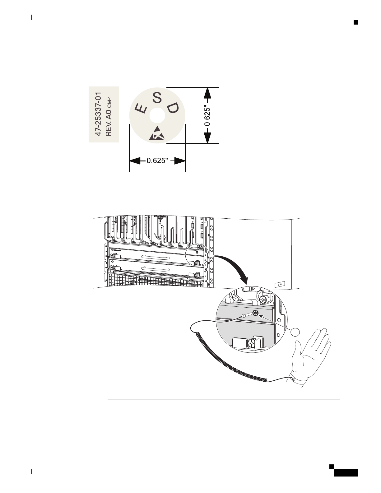
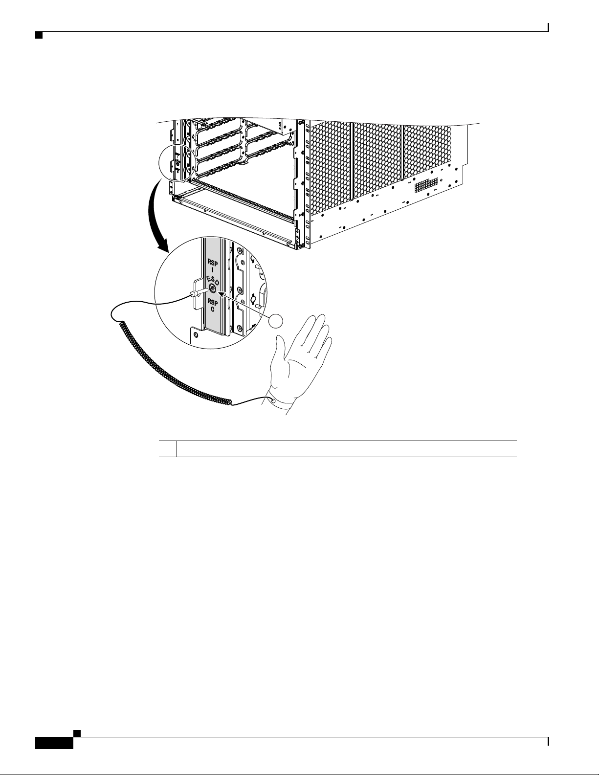
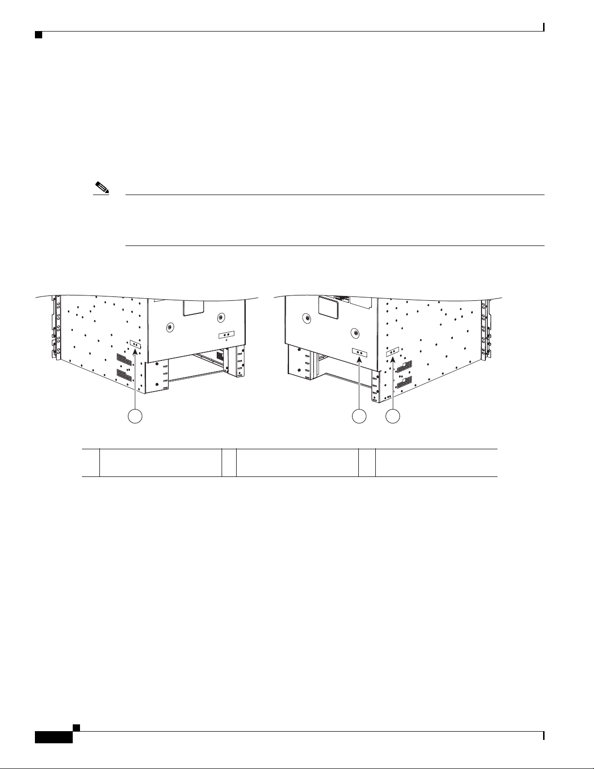
Before you perform any of the procedures in this guide, attach an ESD-preventive strap to your wrist and
connect the leash to the chassis as shown in the figures below.
Figure 1-1 ESD Label Information on Router Chassis
Figure 1-2 Connecting an ESD-Preventive Wrist Strap to the Cisco ASR 9010 Router Chassis
Safety Guidelines
1 Location of chassis socket for ESD strap on the Cisco ASR 9010 Router chassis.
Cisco ASR 9000 Series Aggregation Services Router Hardware Installation Guide
1-3
Page 16
Safety Guidelines
243408
1
Chapter 1 Preparing for Installation
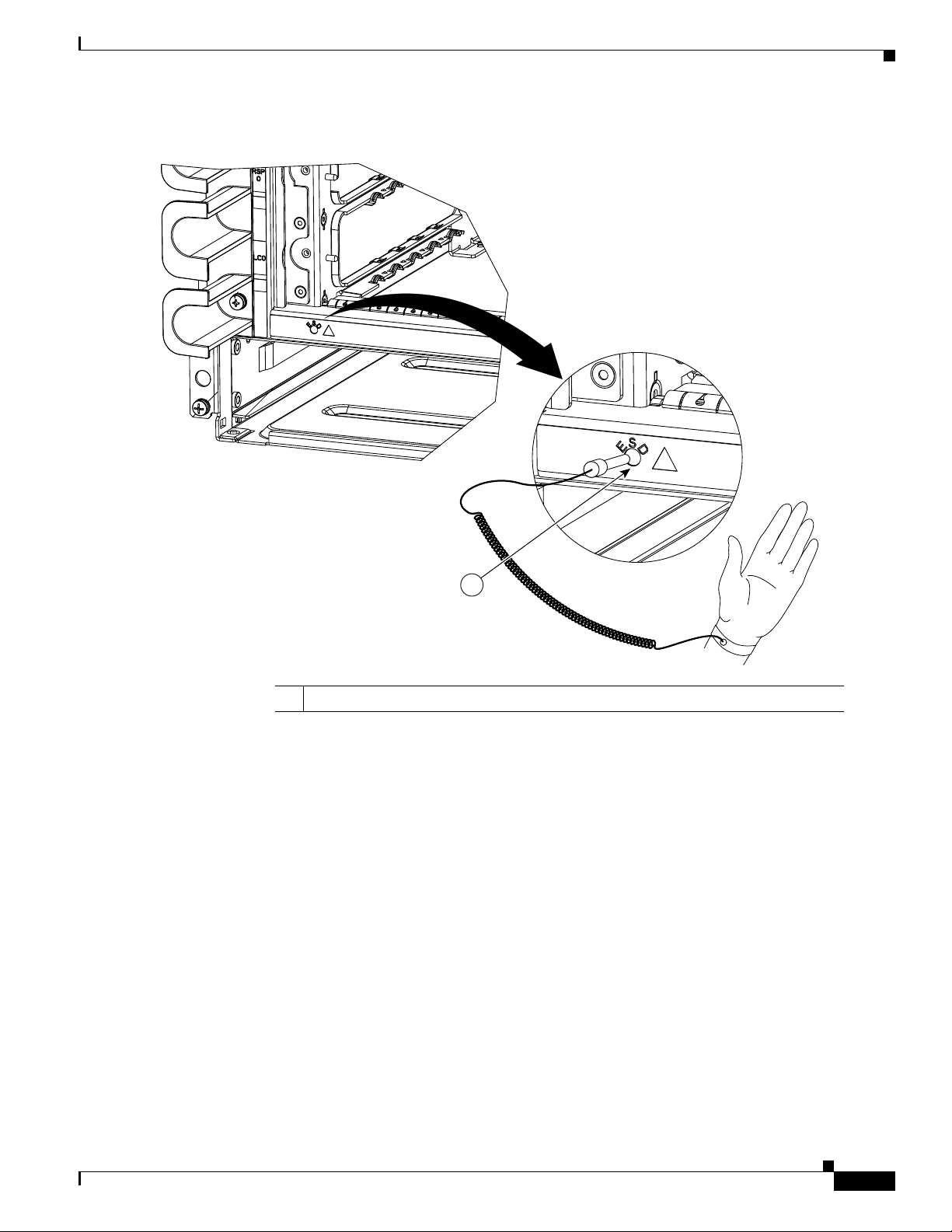
Figure 1-3 Connecting an ESD-Preventive Wrist Strap to the Cisco ASR 9006 Router Chassis
1-4
1 Location of chassis socket for ESD strap on the Cisco ASR 9006 Router chassis.
Cisco ASR 9000 Series Aggregation Services Router Hardware Installation Guide
Page 17
Chapter 1 Preparing for Installation
351293
1
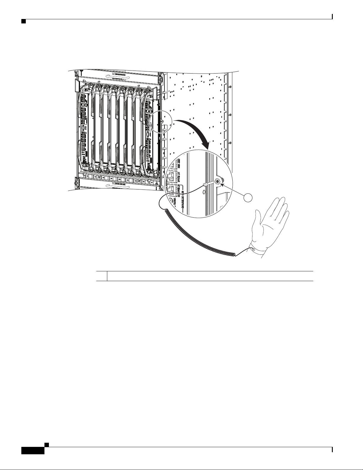
Figure 1-4 Connecting an ESD-Preventive Wrist Strap to the Cisco ASR 9904 Router Chassis
Safety Guidelines
1 Location of chassis socket for ESD strap on the Cisco ASR 9904 Router chassis.
Cisco ASR 9000 Series Aggregation Services Router Hardware Installation Guide
1-5
Page 18
Safety Guidelines
Chapter 1 Preparing for Installation
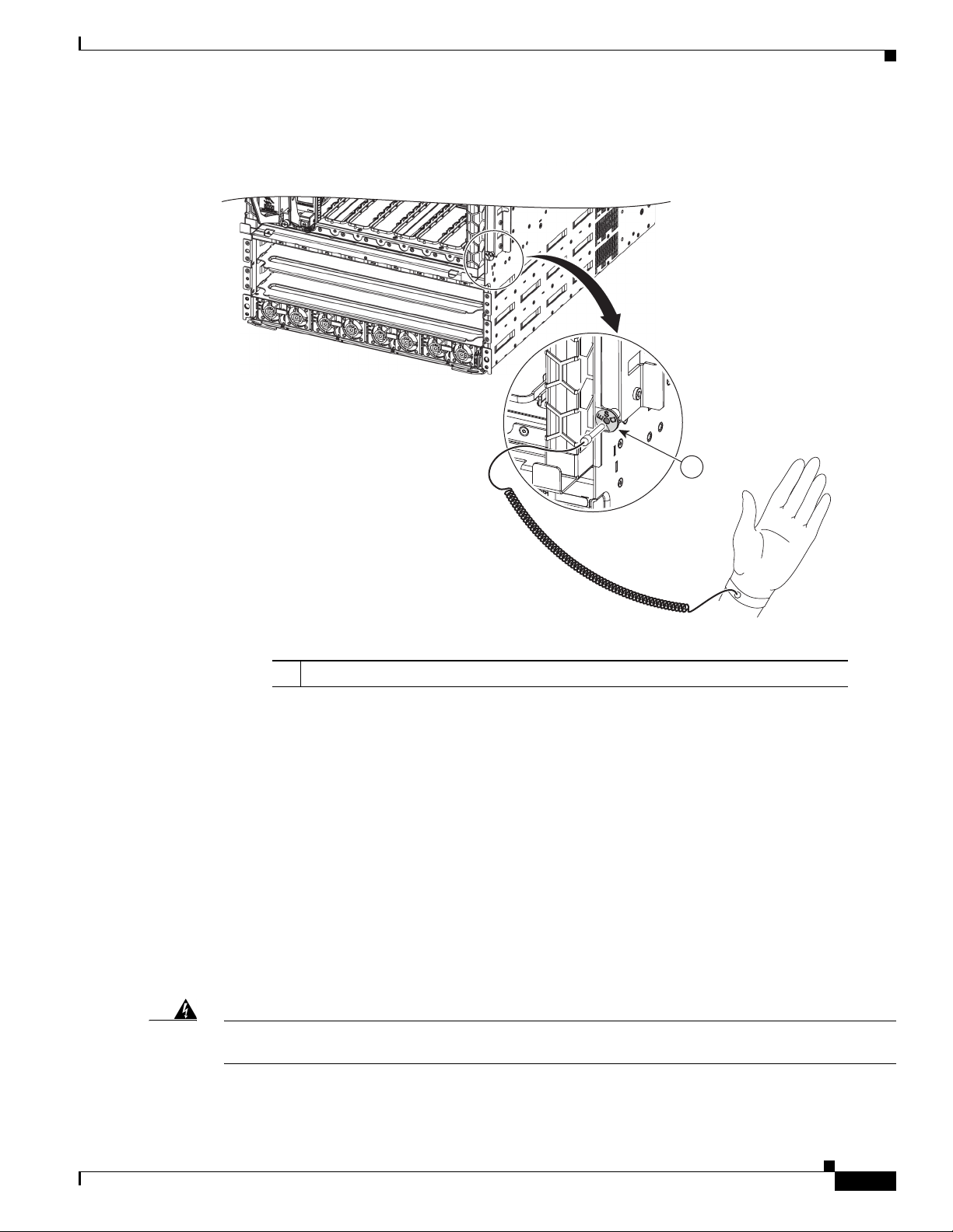
Figure 1-5 Connecting an ESD-Preventive Wrist Strap to the Cisco ASR 9922 Router Chassis
1
302358
1 Location of chassis socket for ESD strap on the Cisco ASR 9922 Router chassis.
1-6
Cisco ASR 9000 Series Aggregation Services Router Hardware Installation Guide
Page 19
Chapter 1 Preparing for Installation
1
303659
Figure 1-6 Connecting an ESD-Preventive Wrist Strap to the Cisco ASR 9912 Router Chassis
Safety Guidelines
Lifting Guidelines
Fully configured Cisco ASR 9000 Series Routers can weigh as much as 1038 pounds (470.28 kg), and
an empty chassis weighs up to 300 pounds (136 kg). These systems are not intended to be moved
frequently. Before you install the router, ensure that your site is properly prepared to prevent moving the
router later to accommodate power sources and network connections.
Use the following lifting guidelines to avoid injury to yourself or damage to the equipment:
• Do not lift equipment alone; have another person help you to lift heavy equipment.
• Ensure that your footing is solid; balance the weight of the object between your feet.
• Lift the equipment slowly; never move suddenly or twist your body as you lift.
• Keep your back straight and lift with your legs, not your back. When bending down to lift
Warning
To prevent injury and equipment damage, never attempt to lift or tilt the router chassis using the
handles on the fan tray or on line cards. These handles do not support the weight of the chassis.
1 Location of chassis socket for ESD strap on the Cisco ASR 9912 Router chassis.
equipment, bend at the knees (not at the waist), to reduce the strain on your lower back muscles.
Cisco ASR 9000 Series Aggregation Services Router Hardware Installation Guide
1-7
Page 20

Site Requirement Guidelines
Site Requirement Guidelines
The following sections contain the site requirement guidelines that you should be familiar with before
installing the router:
• Site Wiring Guidelines, page 1-15
• Chassis Air Flow Guidelines, page 1-15
• Rack-Mounting and Air Flow Clearance Guidelines, page 1-20
• Temperature and Humidity Guidelines, page 1-36
• Power Connection Guidelines, page 1-36
• NEBS Supplemental Unit Bonding and Grounding Guidelines, page 1-52
Site Layout and Equipment Dimensions
To help maintain trouble-free operation, adhere to the following precautions and guidelines when
planning your rack installation:
• Install the system in a restrictive access location with means for a permanent ground.
• Ensure the site of the rack includes provisions for source AC or DC power, grounding, and network
interface cables.
Chapter 1 Preparing for Installation
• Allow sufficient space to work around the rack during the installation. You need:
–
At least 3 ft (91.44 cm) adjacent to the rack to move, align, and insert the chassis.
–
At least 2 ft (60.96 cm) in front of the power tray to insert power modules.
• Maintain at least 24 inches (61 cm) of clearance in front of and behind the chassis for maintenance
after installation.
• To mount the router between two posts or rails, the usable aperture (the width between the inner
edges of the two mounting flanges) must be at least:
–
17.50 inches (44.45 cm) for the Cisco ASR 9010 Router.
–
17.75 inches (45.09 cm) for the Cisco ASR 9006 Router.
–
4.74 inches (12.06 cm) for the Cisco ASR 9904 Router.
• To mount the router in a 4-post rack, the usable aperture (the width between the inner edges of the
two mounting flanges) must be at least 17.75 inches (45.09 cm) for the Cisco ASR 9922 Router or
Cisco ASR 9912 Router.
• Height of the Cisco ASR 9010 Router is 37.00 inches (93.98 cm). Most racks accommodate two
ASR 9010 routers.
• Height of the Cisco ASR 9006 Router is 17.50 inches (44.45 cm). Most racks accommodate four
ASR 9006 routers,
• Height of the Cisco ASR 9904 Router is 10.38 inches (26.7 cm). Most racks accommodate four or
more ASR 9904 routers.
• Height of the Cisco ASR 9922 Router is 77.00 inches (195.58 cm). Most racks accommodate one
ASR 9912 router.
• Height of the Cisco ASR 9912 Router is 52.50 inches (133.35 cm). Most racks accommodate one
ASR 9912 router.
1-8
Cisco ASR 9000 Series Aggregation Services Router Hardware Installation Guide
Page 21

Chapter 1 Preparing for Installation
• When fully populated with cards, the router can weigh up to 1038 pounds (470.28 kg). To maintain
equipment rack stability and to ensure your safety, the rack is provided with stabilizing devices.
Make sure you install the stabilizers before installing the router.
• If you use a telco-style rack, the weight of the chassis is cantilevered off of the two rack posts. Make
sure that:
–
–
• When mounting the router in a telco-style rack or 4-post rack, be sure to use all of the screws
provided to secure the chassis to the rack posts.
• Install the cable-management brackets included with the router to keep cables organized. Be sure to:
–
–
• To avoid noise interference in network interface cables, do not route them directly across or along
power cables.
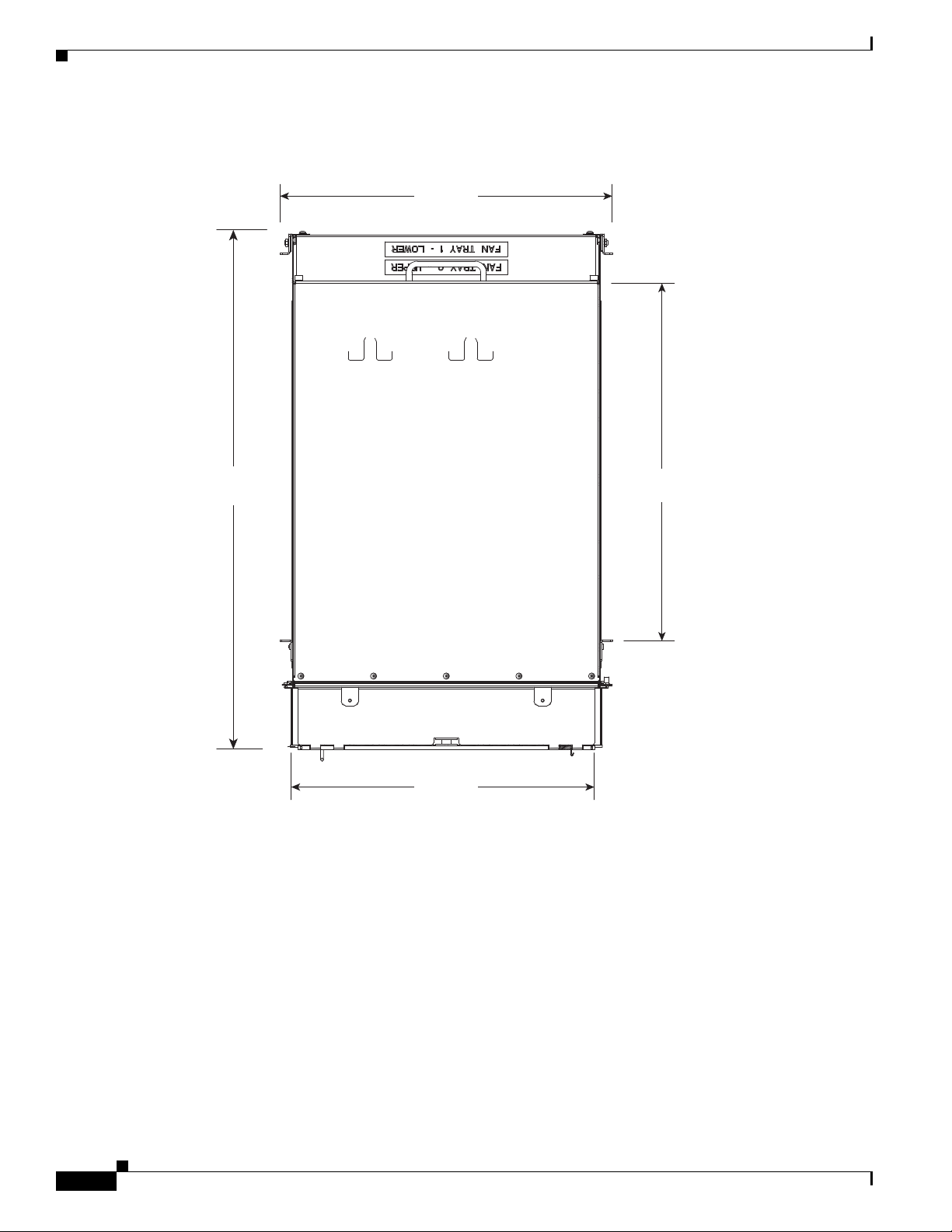
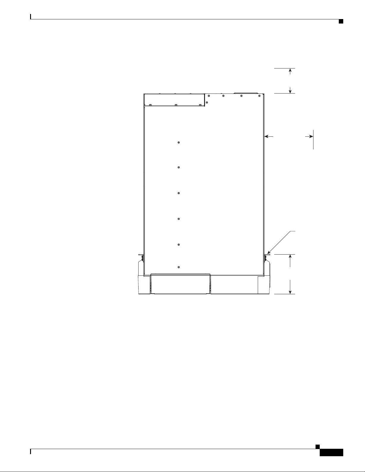
Figure 1-7 shows the top-down view chassis dimensions of the Cisco ASR 9010 Router.
Figure 1-8 shows the top-down view chassis dimensions of the Cisco ASR 9006 Router.
Site Requirement Guidelines
Weight of the router does not make the frame unstable.
Frame is bolted to the floor and is secured to the building structure using either wall brackets or
overhead brackets.
Use appropriate strain-relief methods to protect cables and equipment connections.
Make sure that cables from other equipment installed in the rack do not restrict access to the
card cages.
Figure 1-9 shows the top-down view chassis dimensions of the Cisco ASR 9904 Router.
Figure 1-10 shows the top-down view chassis dimensions of the Cisco ASR 9922 Router.
Figure 1-11 shows the top-down view chassis dimensions of the Cisco ASR 9912 Router.
Cisco ASR 9000 Series Aggregation Services Router Hardware Installation Guide
1-9
Page 22
Site Requirement Guidelines
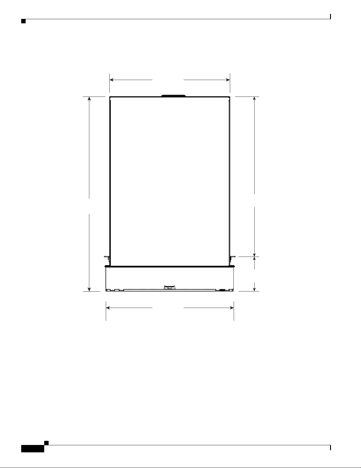
Figure 1-7 Cisco ASR 9010 Router Chassis Footprint and Dimensions—Top-Down View
Chapter 1 Preparing for Installation
Rear of chassis
17.38 in
(44.15 cm)
28.93 in
(73.48 cm)
18.92 in
(48.06 cm)
Front of chassis
23.21 in
(58.95 cm)
5.04 in
(12.80 cm)
243432
1-10
Cisco ASR 9000 Series Aggregation Services Router Hardware Installation Guide
Page 23
Chapter 1 Preparing for Installation
243430
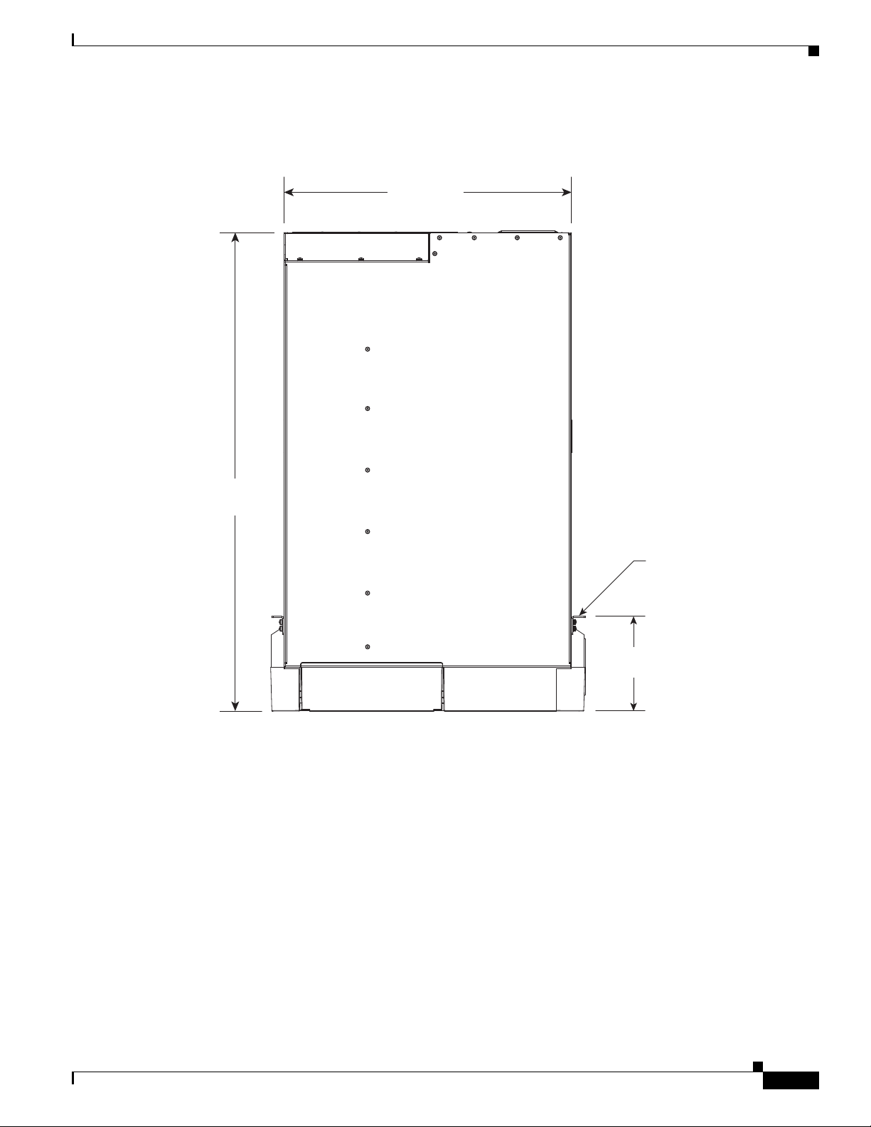
Rear of chassis
Front of chassis
28.93 in
(73.48 cm)
17.38 in
(44.15 cm)
5.73 in
(14.55 cm)
Rack
mounting
surface
Figure 1-8 Cisco ASR 9006 Router Chassis Footprint and Dimensions—Top-Down View
Site Requirement Guidelines
Cisco ASR 9000 Series Aggregation Services Router Hardware Installation Guide
1-11
Page 24
Site Requirement Guidelines
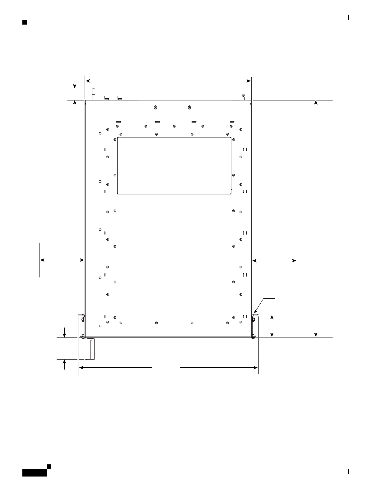
Figure 1-9 Cisco ASR 9904 Router Chassis Footprint and Dimensions—Top-Down View
2.45 in
(6.22 cm)
Chapter 1 Preparing for Installation
Rear of chassis
17.57 in
(44.64 cm)
6.00 in
(15.24 cm)
2.282 in
(5.79 cm)
18.97 in
(48.19 cm)
Front of chassis
25.02 in
(63.54 cm)
6.00 in
(15.24 cm)
Rack
mounting
surface
2.45 in
(6.22 cm)
351294
1-12
Cisco ASR 9000 Series Aggregation Services Router Hardware Installation Guide
Page 25
Chapter 1 Preparing for Installation
343945
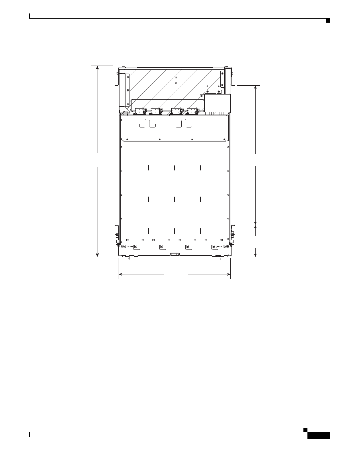
Rear of chassis
Front of chassis
5.05 in
(13.97 cm)
17.60 in
(44.70 cm)
30.11 in
(76.48 cm)
22 in
(55.88 cm)
Figure 1-10 Cisco ASR 9922 Router Chassis Footprint and Dimensions—Top-Down View
Site Requirement Guidelines
Cisco ASR 9000 Series Aggregation Services Router Hardware Installation Guide
1-13
Page 26
Site Requirement Guidelines
303667
Rear of chassis
Front of chassis
17.60 in
(44.70 cm)
29.44 in
(74.78 cm)
18.97 in
(48.18 cm)
22 in
(55.88 cm)
Figure 1-11 Cisco ASR 9912 Router Chassis Footprint and Dimensions—Top-Down View
Chapter 1 Preparing for Installation
1-14
Cisco ASR 9000 Series Aggregation Services Router Hardware Installation Guide
Page 27
Chapter 1 Preparing for Installation
Site Wiring Guidelines
When planning the location of the router, consider distance limitations for signaling, electromagnetic
interference (EMI), and connector compatibility. If the wiring is run for any significant distance in an
electromagnetic field, interference can occur between the field and the signals on the wires. Poor wiring
can cause:
• Radio interference emanating from the wires.
• Strong EMI, especially when caused by lightning or radio transmitters. EMI can destroy the signal
drivers and receivers in the router, and can even create an electrical hazard by conducting power
surges through lines and into equipment.
Note To predict and remedy strong EMI, you may need to consult with experts in radio frequency
interference (RFI).
Site wiring is unlikely to emit radio interference if you use twisted-pair cable with a good distribution
of grounding conductors. Use a high-quality twisted-pair cable with one ground conductor for each data
signal, when applicable.
Give special consideration to the effect of a lightning strike in your vicinity, especially if the wiring
exceeds the recommended distances, or if it passes between buildings. The electromagnetic pulse (EMP)
caused by lightning or other high-energy phenomena can easily induce enough energy into unshielded
conductors to destroy electronic devices. If you have experienced EMP problems in the past, you may
want to consult experts in electrical surge suppression and shielding.
Most data centers cannot resolve infrequent but potentially catastrophic problems without pulse meters
and other special equipment. In addition, these problems can take a great deal of time to identify and
resolve. We recommend that you take the necessary precautions to avoid these problems by providing a
properly grounded and shielded environment, with special attention to issues of electrical surge
suppression.
Site Requirement Guidelines
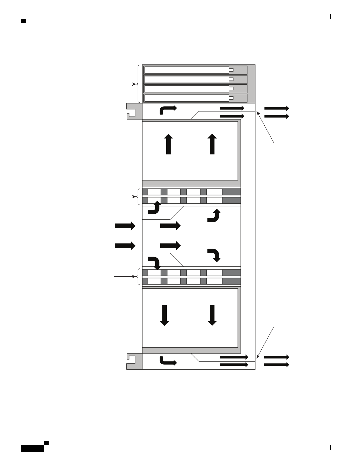
Chassis Air Flow Guidelines
Table 1-1 describes how cool air is circulated through the Cisco ASR 9000 Series Routers.
Table 1-1 Chassis Air Flow Guidelines
Router Type Chassis Air Flow
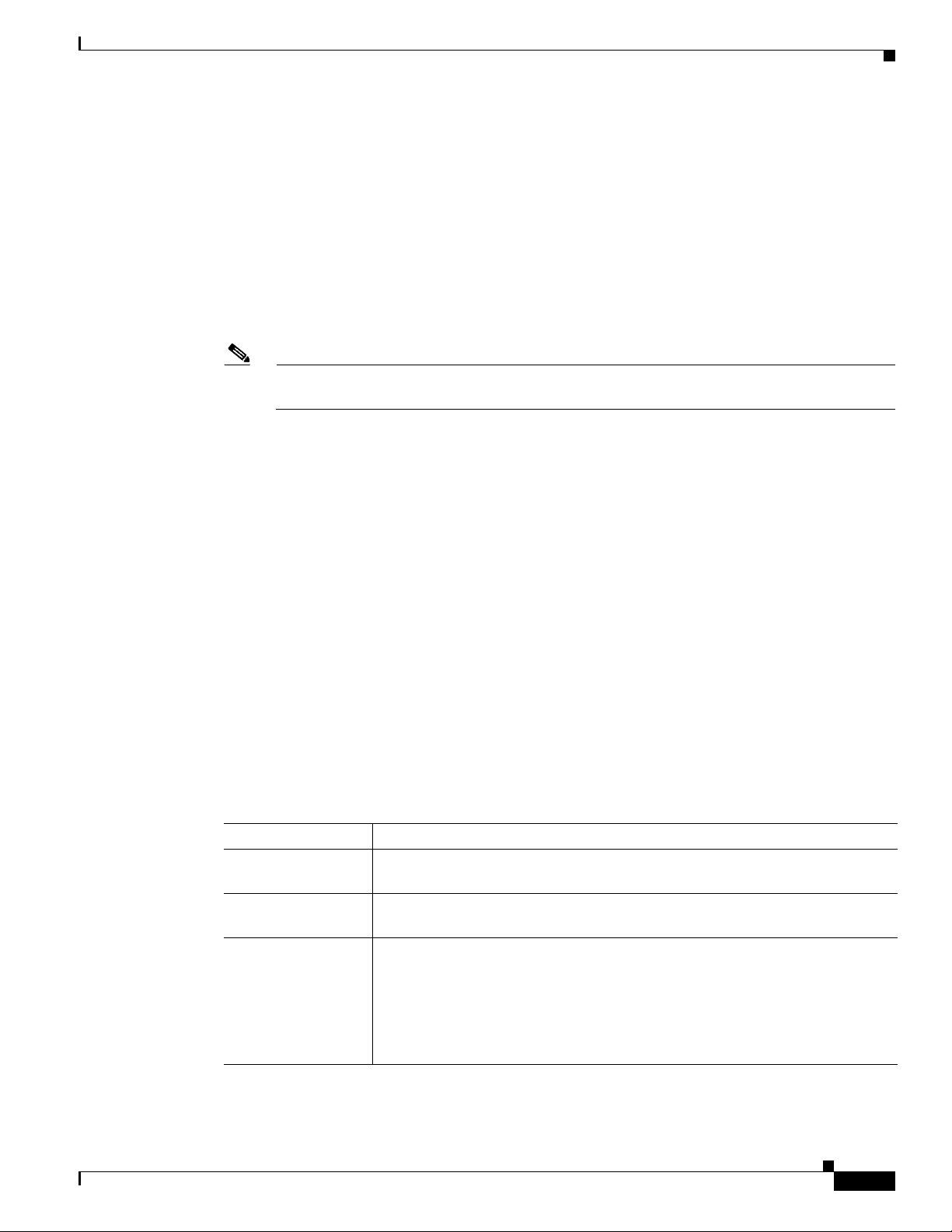
Cisco ASR 9010 Air is circulated by two fan trays located underneath the Route Switch Processor
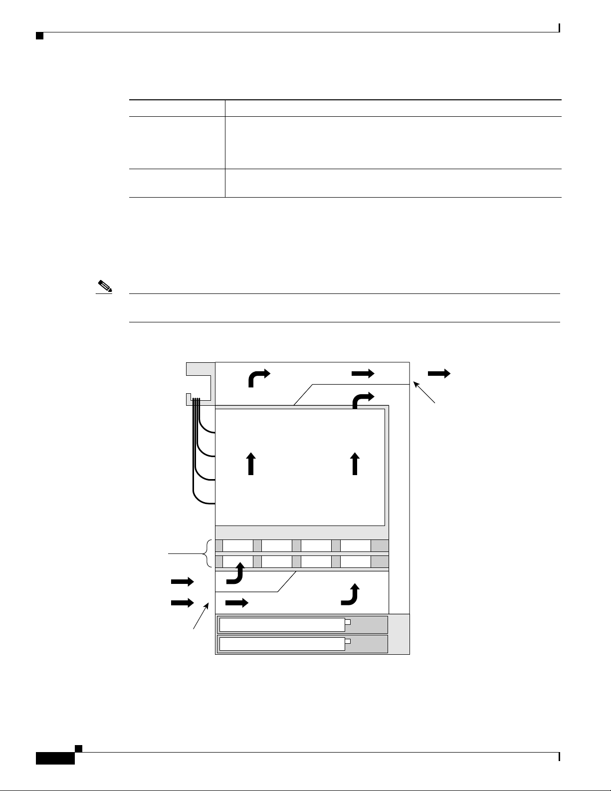
Cisco ASR 9006 Air is circulated by two fan trays located along the top left side above the RSP
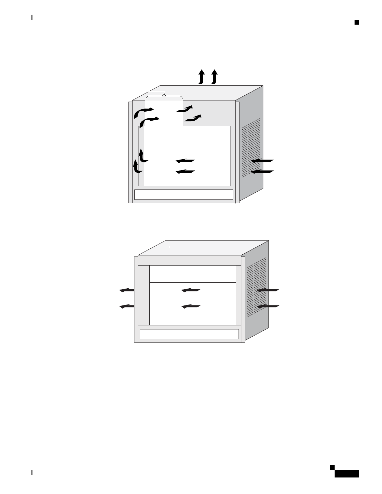
Cisco ASR 9904 Air is circulated side-to-side by a single fan tray located along the left side of
(RSP) and line cards as shown in Figure 1-12.
and line cards as shown in Figure 1-13.
the chassis as shown in Figure 1-14.
If the router is installed in a 2-post 23-inch rack, air flow is circulated
front-to-back. Optionally, you can install air baffles on the chassis to help
isolate the exhaust air from the intake air. For more information, see Installing
Optional Air Baffles on the Cisco ASR 9904 Router, page 2-82.
Cisco ASR 9000 Series Aggregation Services Router Hardware Installation Guide
1-15
Page 28
Site Requirement Guidelines
242696
Power modules
Power modules
Fan trays
Front air
intake
Rear air
exhaust plenum
Air exhaust
Room air
RSPs and line cards
Table 1-1 Chassis Air Flow Guidelines (continued)
Router Type Chassis Air Flow
Cisco ASR 9922 Air circulated by four fan trays as shown in Figure 1-15. Two fan trays are
Cisco ASR 9912 Air is circulated by two fan trays located above the line cards as shown in
The fan trays maintain acceptable operating temperatures for the internal components by drawing in cool
air through the air filter, and circulating the air through the card cage. Each power supply is also
equipped with fans that draw cooler air into the front of the power supply and force warmer air out of
the back of the chassis. For information about the types of fan trays used in the chassis, see Power
Module Fans, page 4-34.
Note See Rack-Mounting and Air Flow Clearance Guidelines, page 1-20 for details on air-flow clearance
requirements for installation in an enclosed 4-post rack.
Chapter 1 Preparing for Installation
located between the line cards in the top cage and the RP and Switch Fabric
Cards (FCs) in the middle cage. Another two fan trays are located between the
middle cage and the line cards in the bottom cage.
Figure 1-16.
Figure 1-12 Air Flow Path through the Cisco ASR 9010 Router—Side View
1-16
Cisco ASR 9000 Series Aggregation Services Router Hardware Installation Guide
Page 29
Chapter 1 Preparing for Installation
243379
Air exhaust
RSPs and line cards
Room air
Power modules
Fan trays
Figure 1-13 Air Flow Path through the Cisco ASR 9006 Router—Front View
Site Requirement Guidelines
Figure 1-14 Air Flow Path through the Cisco ASR 9904 Router—Front View
RSPs and line cards
Air exhaust
Room air
Power modules
351295
Cisco ASR 9000 Series Aggregation Services Router Hardware Installation Guide
1-17
Page 30
Site Requirement Guidelines
Rear Air
exhaust plenum
Rear Air
exhaust plenum
Air exhaust
Air exhaust
Line cards
RPs and FCs
Fan trays
Fan trays
Power modules
Line cards
RPs and FCs
343957
Chapter 1 Preparing for Installation
Figure 1-15 Air Flow Path through the Cisco ASR 9922 Router—Side View
1-18
Cisco ASR 9000 Series Aggregation Services Router Hardware Installation Guide
Page 31

Chapter 1 Preparing for Installation
Rear Air
exhaust plenum
Air exhaust
Line cards
RPs and FCs
Fan trays
Power trays
303670
Figure 1-16 Air Flow Path through the Cisco ASR 9912 Router—Side View
Site Requirement Guidelines
When selecting a site to install the router, observe the following guidelines:
• Dust-free area—The site should be as dust-free as possible. Dusty environments can clog the air
filter or power supply intake vents, reducing the cooling air flow through the router. Clogged filters
and vents can cause an overtemperature condition in the router.
• Unrestricted air-flow—Allow sufficient air-flow by maintaining a minimum of 6 in (15.24 cm) of
clearance at both the inlet and exhaust openings on the chassis and the power modules. If the air flow
is blocked or restricted, or if the inlet air is too warm, an overtemperature condition can occur within
the router. Under extreme conditions, the environmental monitoring system powers off the router to
protect the components.
Cisco ASR 9000 Series Aggregation Services Router Hardware Installation Guide
1-19
Page 32
Site Requirement Guidelines
243453
a b c
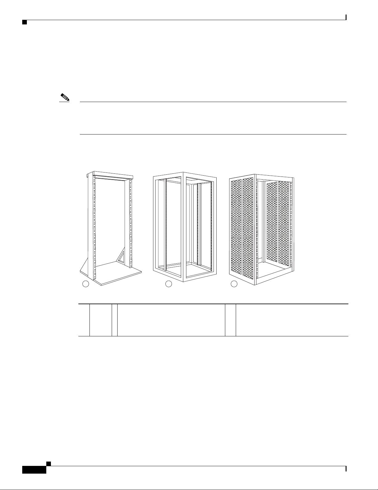
Rack-Mounting and Air Flow Clearance Guidelines
The Cisco ASR 9010 Router, Cisco ASR 9006 Router, and Cisco ASR 9904 Router c an be installed in
most 2-post, 4-post, or telco-style 19-inch equipment racks that comply with the Electronics Industries
Association (EIA) standard for equipment racks (EIA-310-D).
Note The Cisco ASR 9922 Router and Cisco ASR 9912 Router can be mounted only in a 4-post rack. The rack
must have at least two posts with mounting flanges to mount the router chassis. The distance between
the center lines of the mounting holes on the two mounting posts must be 18.31 inches ± 0.06 inch
(46.50 cm ± 0.15 cm).
Figure 1-17 shows an examples of typical 2-post and 4-post telco-type equipment racks.
Figure 1-17 Telco-Type Equipment Racks
Chapter 1 Preparing for Installation
a Tel c o -
style
rack
b Free-standing, 4-post open rack with
two mounting posts in the front, two
mounting posts in the back or along each
side.
Cisco ASR 9000 Series Aggregation Services Router Hardware Installation Guide
1-20
c Free-standing enclosed rack with
perforated sides and two mounting posts
in the front.
Page 33
Chapter 1 Preparing for Installation
Telco 2-Post Rack
Item a in Figure 1-17 shows a telco-style rack. The telco-style rack is an open frame consisting of two
posts tied together by a cross-bar at the top and a floor stand at the bottom.
This type of rack is usually secured to the floor and sometimes to an overhead structure or wall for
additional stability. The router chassis can be installed in the telco-style rack only in a front-mounted
position.
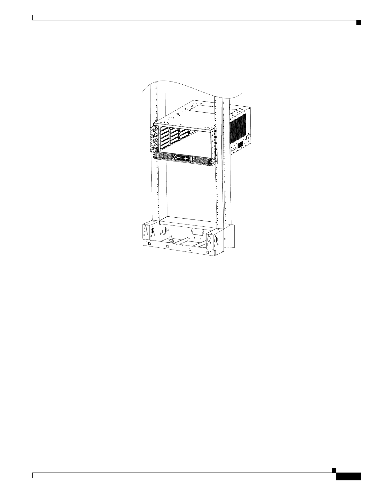
In the front-mounted position, you secure the chassis rack-mounting brackets directly to the rack posts
(see Figure 1-18 for the Cisco ASR 9010 Router, Figure 1-19 for the Cisco ASR 9006 Router, and
Figure 1-20 for the Cisco ASR 9904 Router). Two rear mounting brackets are provided for mounting the
Cisco ASR 9010 Router in a 2-post rack.
Note The mounting brackets on the Cisco ASR 9006 Router chassis have a pair of holes at the top and bottom
of each bracket; the remaining openings in the brackets are slots. When mounting the router in a 2-post
rack, you must first use the holes to locate and position the brackets on the rack. Insert the screws through
the bracket holes into the rack before inserting screws through the bracket slots.
Site Requirement Guidelines
Figure 1-18 Cisco ASR 9010 Router Mounted in a 2-Post Rack
243186
Cisco ASR 9000 Series Aggregation Services Router Hardware Installation Guide
1-21
Page 34
Site Requirement Guidelines
243496
Figure 1-19 Cisco ASR 9006 Router Mounted in a 2-Post Rack
Chapter 1 Preparing for Installation
1-22
Cisco ASR 9000 Series Aggregation Services Router Hardware Installation Guide
Page 35
Chapter 1 Preparing for Installation
351296
Figure 1-20 Cisco ASR 9904 Router Mounted in a 2-Post Rack
Site Requirement Guidelines
Cisco ASR 9000 Series Aggregation Services Router Hardware Installation Guide
1-23
Page 36
Site Requirement Guidelines
302352
Open 4-Post Rack
Chapter 1 Preparing for Installation
Item b in Figure 1-17 shows a free-standing, 4-post open rack with two mounting posts in the front and
two mounting posts in the back or along the side. The mounting posts in this type of rack are often
adjustable so that you can position the rack-mounted unit within the depth of the rack rather than
flush-mount it with the front of the rack.
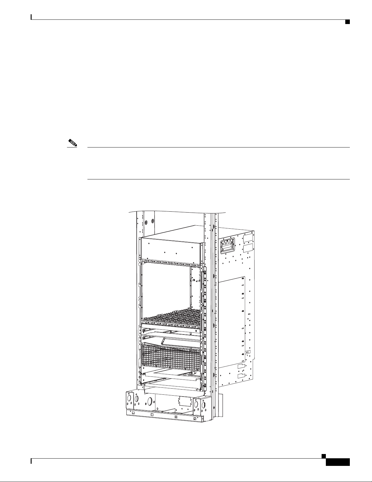
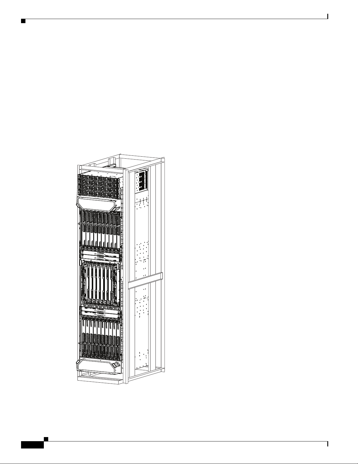
• Two rear mounting brackets are provided for mounting the Cisco ASR 9010 Router in a 4-post rack.
• Two rear mounting brackets and two bottom guide rails are provided for mounting the
Cisco ASR 9922 Router (Figure 2-8) and Cisco ASR 9912 Router (Figure 2-12) in a 4-post rack.
• Rear brackets or are necklaces are not provided for mounting the Cisco ASR 9904 Router in a 4-post
rack.
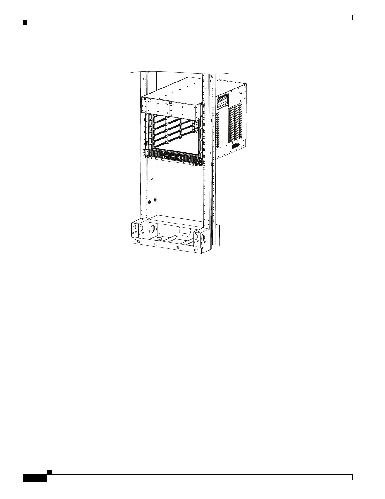
Figure 1-21 Cisco ASR 9912 Router Mounted in an Open 4-Post Rack
1-24
Cisco ASR 9000 Series Aggregation Services Router Hardware Installation Guide
Page 37
Chapter 1 Preparing for Installation
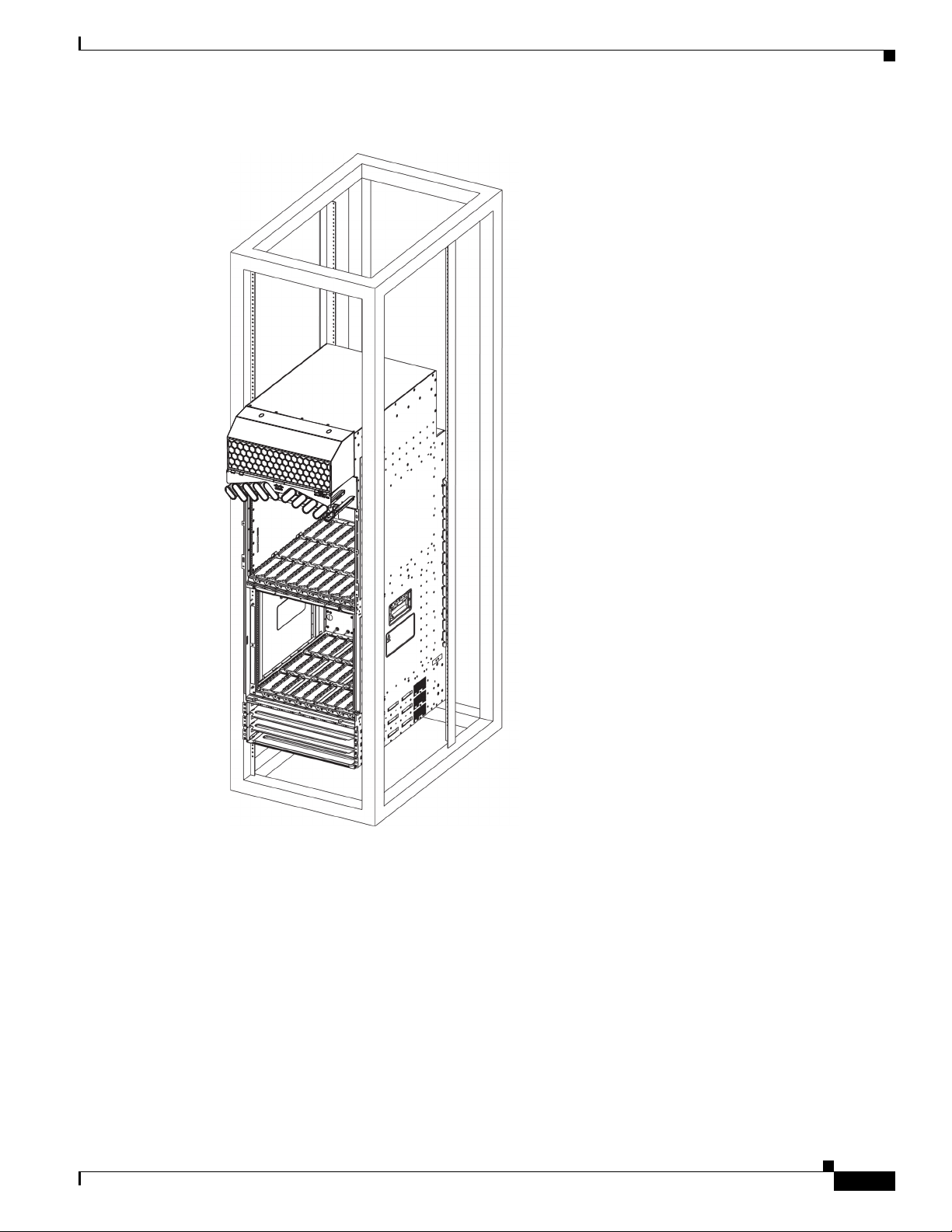
Figure 1-22 Cisco ASR 9912 Router Mounted in an Open 4-Post Rack
Site Requirement Guidelines
303660
Cisco ASR 9000 Series Aggregation Services Router Hardware Installation Guide
1-25
Page 38

Site Requirement Guidelines
4-Post Enclosed Rack with Perforated Sides
Item c in Figure 1-17 shows a free-standing 4-post enclosed rack with perforated sides and two mounting
posts in the front.
Caution Do not install the Cisco ASR 9000 Series Router in any type of fully enclosed rack that does not have
the required perforated sides or doors; the router requires an unobstructed flow of cooling air to maintain
acceptable operating temperatures for its internal components. Installing the router in any type of fully
enclosed rack without proper perforation could disrupt the air-flow, trap heat next to the chassis, and
cause an overtemperature condition inside the router.
Air Flow Guidelines for Enclosed Rack Installation
Follow these guidelines when installing the Cisco ASR 9000 Series Routers in a 4-post enclosed rack.
Cisco ASR 9010 Router Clearance Requirements
Chapter 1 Preparing for Installation
To install a Cisco ASR 9010 Router in a 4-post enclosed cabinet:
• The front and rear doors of the cabinet must be removed or be perforated with a minimum open area
of 65 percent (70 percent for ETSI 800-mm racks).
• Ensure that you have the following clearances around the chassis:
–
Rear: Minimum of 3.15 inches (8.00 cm) of clearance.
–
Sides: Minimum of 2.87 inches (7.28 cm) of clearance on each side of the chassis.
Figure 1-23 shows the side and rear chassis air-flow clearance requirements for mounting the
Cisco ASR 9010 Router in a 4-post enclosed rack.
1-26
Cisco ASR 9000 Series Aggregation Services Router Hardware Installation Guide
Page 39
Chapter 1 Preparing for Installation
245629
Rear of chassis
Front of chassis
ASR 9010
2.87 in
(7.28 cm)
2.87 in
(7.28 cm)
5.04 in
(12.80 cm)
Rack
mounting
surface
3.15 in
(8.00 cm)
Figure 1-23 Cisco ASR 9010 Router Clearance Requirements for an Enclosed 4-Post Rack
Site Requirement Guidelines
Installation
Cisco ASR 9000 Series Aggregation Services Router Hardware Installation Guide
1-27
Page 40

Site Requirement Guidelines
Cisco ASR 9006 Clearance Requirements
To install a Cisco ASR 9006 Router in a 4-post enclosed cabinet:
• The front and rear doors of the cabinet must be removed or be perforated with a minimum open area
of 70 percent. In addition, the right side panel must be removed or perforated with a minimum of 65
percent open area (70 percent for ETSI 800-mm racks).
• There must be a minimum unobstructed space of 6 inches (15.24 cm) between the router’s right side
air inlet and the adjacent wall or cabinet side panel, and a minimum unobstructed space of 6 inches
(15.24 cm) between adjacent cabinets. In addition, there should be no exhaust from any source
blowing into the right side panel of the cabinet.
–
Rear chassis clearance: Minimum of 2.50 inches (6.40 cm) of clearance.
–
Sides chassis clearance: Minimum of 6 inches (15.24 cm) of clearance on the right side of the
chassis (as viewed from the front). There is no clearance requirement for the left side of the
chassis.
Figure 1-24 shows the side and rear chassis air-flow clearance requirements for mounting the Cisco ASR
9006 Router in a 4-post enclosed rack.
Chapter 1 Preparing for Installation
1-28
Cisco ASR 9000 Series Aggregation Services Router Hardware Installation Guide
Page 41
Chapter 1 Preparing for Installation
Figure 1-24 Cisco ASR 9006 Router Clearance Requirements for an Enclosed 4-Post Rack
Site Requirement Guidelines
Installation
Rear of chassis
2.50 in
(6.40 cm)
No minimum clearance
requirement for left
side of chassis.
6.00 in
(15.20 cm)
ASR 9006
Rack
mounting
surface
5.73 in
(14.55 cm)
Front of chassis
Cisco ASR 9000 Series Aggregation Services Router Hardware Installation Guide
245630
1-29
Page 42

Site Requirement Guidelines
Cisco ASR 9904 Clearance Requirements
To install the Cisco ASR 9904 Router in a 4-post enclosed cabinet:
• Ensure that you have the following clearances around the chassis:
–
Rear: Minimum of 2.45 inches (62.2 cm) of clearance.
–
Sides: Minimum of 6.00 inches (152.4 cm) of clearance on each side of the chassis.
Figure 1-25 shows the side and rear chassis air-flow clearance requirements for mounting the Cisco ASR
9904 Router in a 4-post enclosed rack.
Chapter 1 Preparing for Installation
1-30
Cisco ASR 9000 Series Aggregation Services Router Hardware Installation Guide
Page 43

Chapter 1 Preparing for Installation
Figure 1-25 Cisco ASR 9904 Router Clearance Requirements in a 4-Post Rack Installation
Rear of chassis
2.45 in
(6.22 cm)
17.57 in
(44.64 cm)
Site Requirement Guidelines
6.00 in
(15.24 cm)
2.282 in
(5.79 cm)
18.97 in
(48.19 cm)
Front of chassis
25.02 in
(63.54 cm)
6.00 in
(15.24 cm)
Rack
mounting
surface
2.45 in
(6.22 cm)
351294
Cisco ASR 9000 Series Aggregation Services Router Hardware Installation Guide
1-31
Page 44

Site Requirement Guidelines
Cisco ASR 9922 Clearance Requirements
To install the Cisco ASR 9922 Router in a 4-post enclosed cabinet:
• The front and rear doors of the cabinet must be removed or be perforated with a minimum open area
of 70 percent (80 percent for ETSI 800-mm racks).
• Ensure that you have the following clearances around the chassis:
–
Rear: Minimum of 10 inches (25.4 cm) of clearance.
–
Sides: Minimum of 2.87 inches (7.28 cm) clearance on each side of the chassis.
Figure 1-26 shows the clearance requirements for mounting the Cisco ASR 9922 Router in a 4-post
enclosed rack.
Chapter 1 Preparing for Installation
1-32
Cisco ASR 9000 Series Aggregation Services Router Hardware Installation Guide
Page 45

Chapter 1 Preparing for Installation
Figure 1-26 Cisco ASR 9922 Router Clearance Requirements in a 4-Post Rack Installation
Site Requirement Guidelines
10 in
(25.40 cm)
Rear of chassis
2.87 in
(7.28 cm)
Front of chassis
2.87 in
(7.28 cm)
Rack
mounting
surface
4.50 in
(11.43 cm)
302422
Cisco ASR 9000 Series Aggregation Services Router Hardware Installation Guide
1-33
Page 46

Site Requirement Guidelines
Cisco ASR 9912 Clearance Requirements
To install the Cisco ASR 9912 Router in a 4-post enclosed cabinet:
• The front and rear doors of the cabinet must be removed or be perforated with a minimum open area
of 70 percent open area (80 percent for ETSI 800-mm racks).
• Ensure that you have the following clearances around the chassis:
–
Rear: Minimum of 10 inches (25.4 cm) of clearance.
–
Sides: Minimum of 2.87 inches (7.28 cm) of clearance on each side of the chassis.
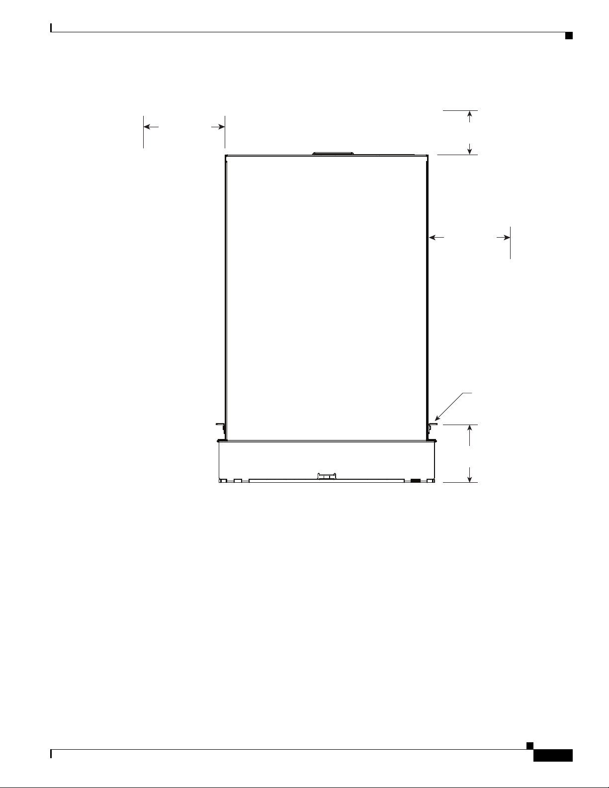
Figure 1-27 shows the side and rear chassis air-flow clearance requirements for mounting the router in
a 4-post enclosed rack.
Chapter 1 Preparing for Installation
1-34
Cisco ASR 9000 Series Aggregation Services Router Hardware Installation Guide
Page 47

Chapter 1 Preparing for Installation
Figure 1-27 Cisco ASR 9912 Router Clearance Requirements in a 4-Post Rack Installation
Site Requirement Guidelines
10 in
(25.40 cm)
Rear of chassis
2.87 in
(7.28 cm)
Front of chassis
2.87 in
(7.28 cm)
Rack
mounting
surface
6.30 in
(16 cm)
303661
Cisco ASR 9000 Series Aggregation Services Router Hardware Installation Guide
1-35
Page 48
Site Requirement Guidelines
Temperature and Humidity Guidelines
The operating and nonoperating environmental site requirements are listed in Tab l e A-2. The router
normally operates within the ranges listed in the table; however, if a temperature measurement is
approaching a minimum or maximum parameter, it indicates a potential problem. Maintain normal
operation by anticipating and correcting environmental anomalies before they approach critical values
by properly planning and preparing your site before you install the router.
Power Connection Guidelines
You can configure the router with either an AC input or DC input power subsystem, so the site power
source requirements differ depending on the power subsystem in your router. Ensure all power
connection wiring conforms to the rules and regulations in the National Electrical Code (NEC) as well
as local codes.
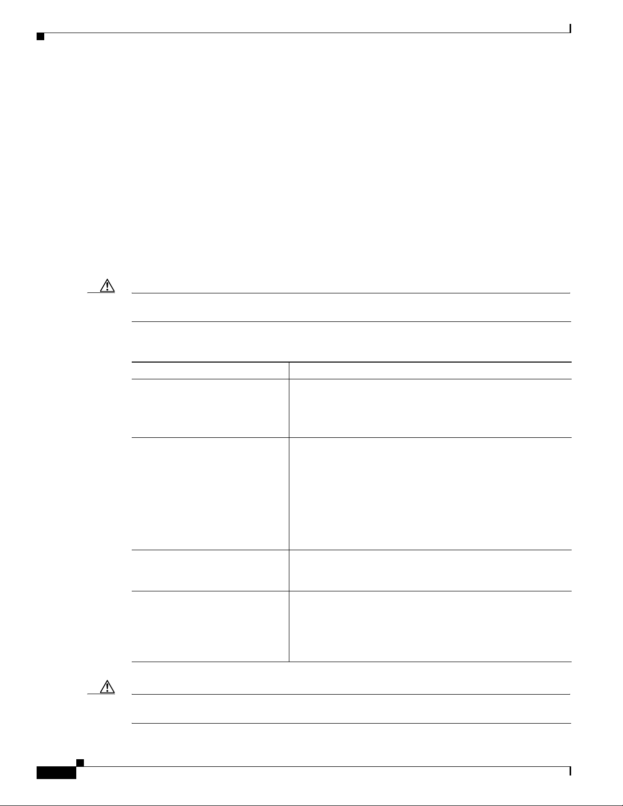
Caution Each Cisco ASR 9000 Series Router is powered by only one type of input: AC or DC. A hybrid (AC+DC)
power configuration is not supported.
Chapter 1 Preparing for Installation
Table 1-2 Cisco ASR 9000 Series Routers Supported Power Systems
Router Supported Power Systems
Cisco ASR 9006 Version 1: Supports up to three power modules in the power tray.
Version 2: Supports up to four power modules in the power tray
Compatible only with Cisco IOS XR Software Release 4 and
later Cisco IOS XR software releases.
Cisco ASR 9010 Version 1: Supports up to three power modules in the power tray.
Version 2: Supports up to four power modules in the power tray
Compatible only with Cisco IOS XR Software Release 4 and
later Cisco IOS XR software releases.
Version 3: Supports up to four DC power modules in the DC
power tray and up to three AC power modules in the AC power
tray. Compatible only with Cisco IOS XR Software Release
5.3.0 and later Cisco IOS XR software releases.
Cisco ASR 9904 Version 2: Supports up to four power modules in the power tray.
Compatible only with Cisco IOS XR Software Release 4 and
later Cisco IOS XR software releases.
Cisco ASR 9922, Cisco ASR 9912 Version 2: Supports up to four power modules in the power tray.
Version 3: Supports up to four DC power modules in the DC
power tray and up to three AC power modules in the AC power
tray. Compatible only with Cisco IOS XR Software Release
5.3.0 and later Cisco IOS XR software releases.
1-36
Caution Proper grounding is necessary to avoid damage from lightning and power surges. See NEBS
Supplemental Unit Bonding and Grounding Guidelines, page 1-52 for grounding requirements.
Cisco ASR 9000 Series Aggregation Services Router Hardware Installation Guide
Page 49
Chapter 1 Preparing for Installation
AC-Powered Routers
AC power modules operate in the input range of 180 VAC to 264 VAC, 47 to 63 Hz (nominal input level
of 200 to 240 VAC). Refer to Tab le 1-3 and Tabl e 1-4 for the minimum required AC service for version
1 and version 2 power modules.
Power redundancy requirements vary based on the system configuration (number and type of line cards,
etc.). AC-powered systems are 2N protected. A minimum of two power supplies are required for
redundant operation. Refer to the Cisco ASR 9000 Power Calculator at the following URL to determine
actual redundancy requirements for any given configuration: http://tools.cisco.com/cpc/launch.jsp.
Each of the AC power inputs requires a separate dedicated branch circuit. Note that the circuit breaker
and fuse lockout procedures should follow the rules and regulations in the National Electrical Code
(NEC) and any local codes. For a list of the nominal and acceptable value ranges for source AC power,
see Tabl e A- 5.
Table 1-3 lists the AC input power cord options, specifications, and Cisco product numbers for the AC
input version 1 power supply modules. Tabl e 1- 4 lists the AC input power cord options, specifications,
and Cisco product numbers for the AC input version 2 power supply modules.
Note Before connecting AC input power cords to the power system, make sure that the power cords are not
energized.
Site Requirement Guidelines
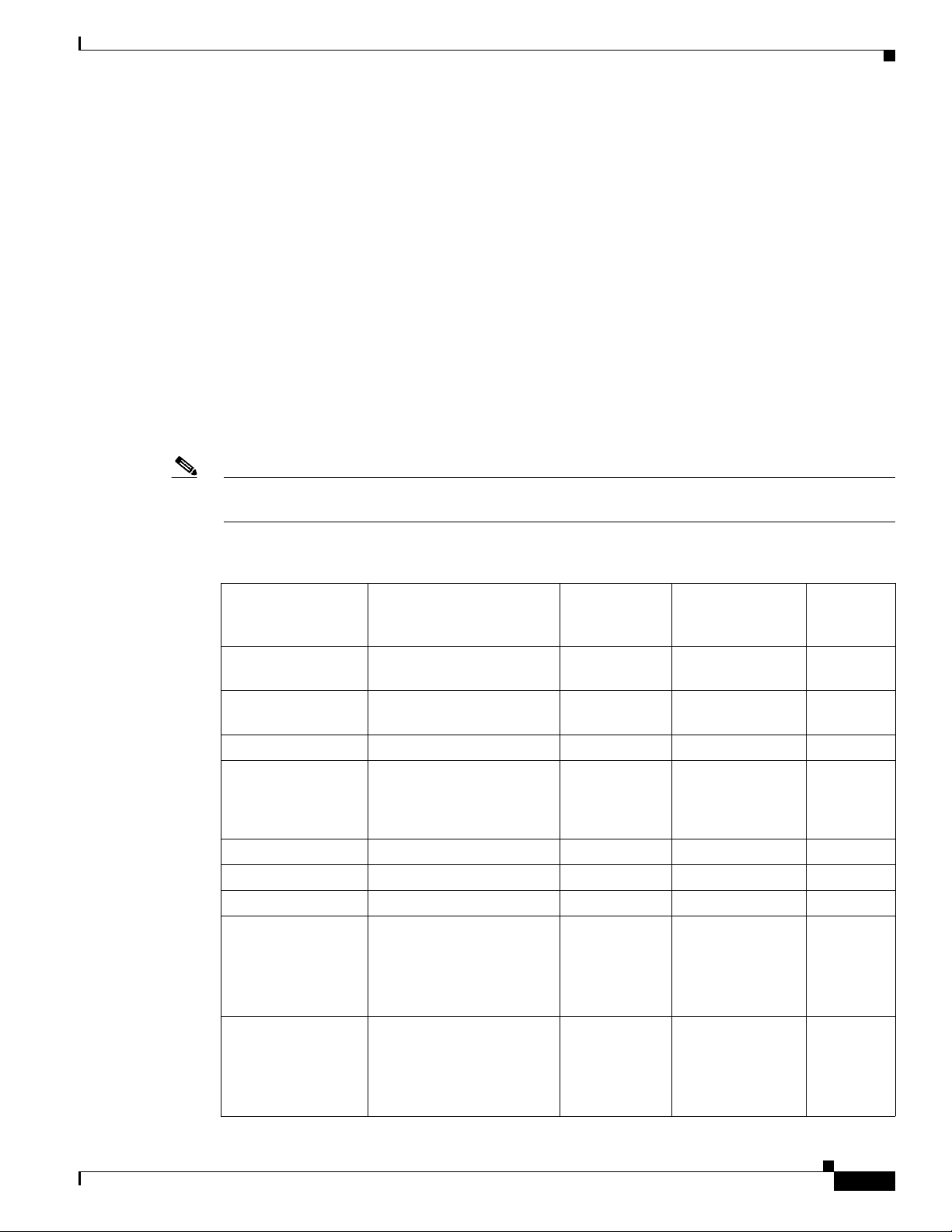
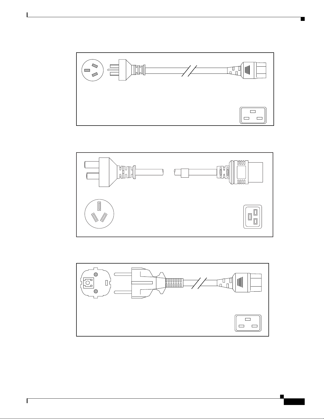
Table 1-3 AC Input Power Cord Options for Version 1 Power System
Power Cord
Reference
Locale Part Number Length Plug Rating
Australia,
CAB-7513ACA= 14 ft (4.3 m) 15 A, 250 VAC Figure 1-28
Illustration
New Zealand
Australia,
CAB-AC-16A-AUS= 14 ft (4.3 m) 16A, 250 VAC Figure 1-29
New Zealand
China CAB-AC16A-CH= 14 ft (4.3 m) 16 A, 250 VAC Figure 1-30
Continental Europe CAB-7513ACE=
CAB-2500W-EU=
CAB-AC-2500W-EU=
14 ft (4.3 m) 16 A, 250 VAC
16 A, 250 VAC
16 A, 250 VAC
Figure 1-31
Figure 1-32
Figure 1-33
International CAB-AC-2500W-INT= 14 ft (4.3 m) 16 A, 250 VAC Figure 1-34
Israel CAB-AC-2500W-ISRL= 14 ft (4.3 m) 16 A, 250 VAC Figure 1-35
Italy CAB-7513ACI= 14 ft (4.3 m) 16 A, 250 VAC Figure 1-36
Japan, North
CAB-AC-2500W-US1= 14 ft (4.3 m) 20 A, 250 VAC Figure 1-37
America
(nonlocking plug)
200–240VAC
operation
Japan, North
CAB-AC-C6K-TWLK= 14 ft (4.3 m) 20 A, 250 VAC Figure 1-38
America (locking
plug)
200–240VAC
operation
Cisco ASR 9000 Series Aggregation Services Router Hardware Installation Guide
1-37
Page 50
Site Requirement Guidelines
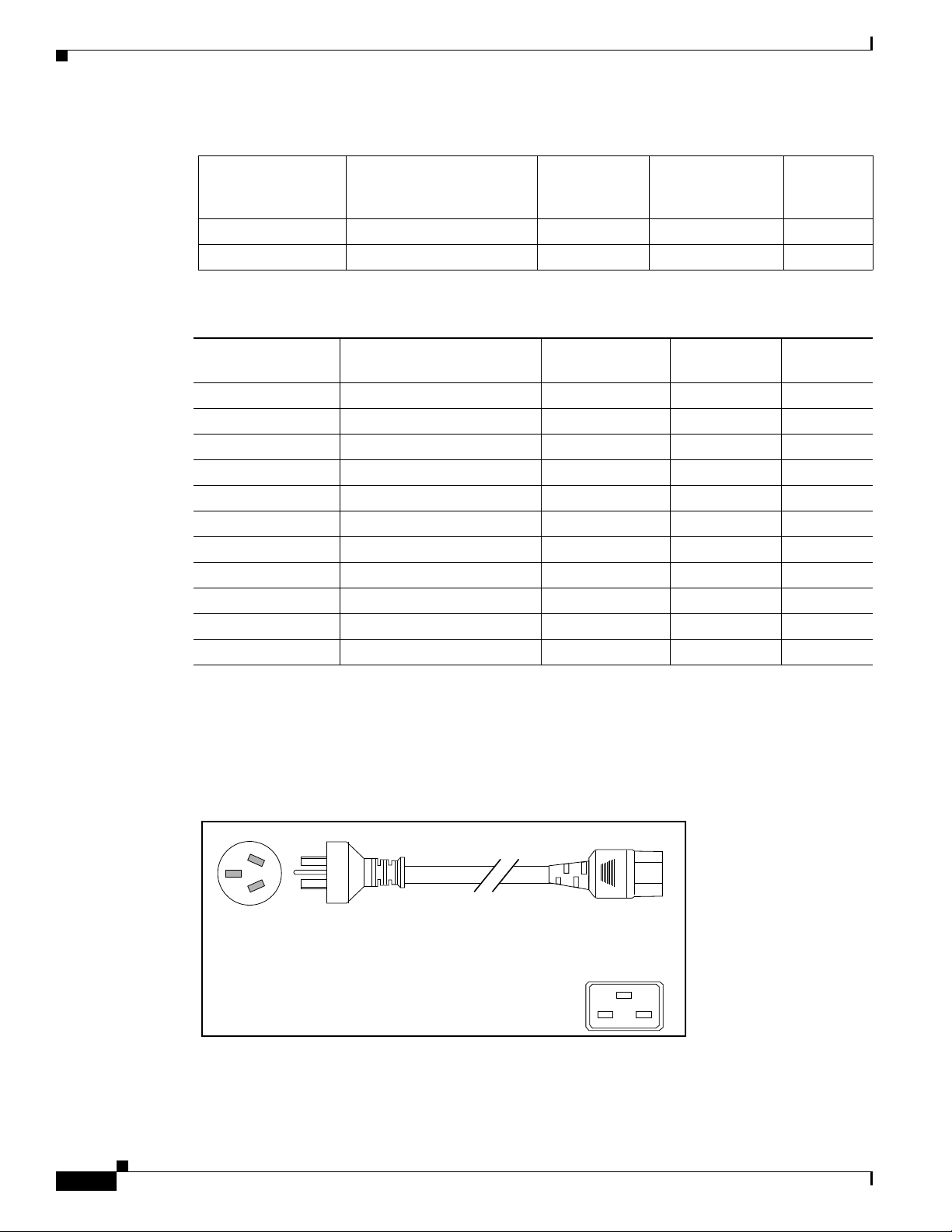
Cordset rating: 15 A, 250 V
Length: 14 ft 0 in. (4.26 m)
Connector: IEC 60320 C19
Plug: SAA AS 3112
Table 1-3 AC Input Power Cord Options for Version 1 Power System
Locale Part Number Length Plug Rating
South Africa CAB-7513ACSA= 14 ft (4.3 m) 16 A, 250 VAC Figure 1-39
Switzerland CAB-ACS-16= 14 ft (4.3 m) 16 A, 250 VAC Figure 1-40
Table 1-4 AC Input Power Cord Options for Version 2 and Version 3 Power System
Locale Part Number Length Plug Rating
China PWR-CAB-AC-CHN= 13.9 ft (4.3 m) 16 A, 250 V Figure 1-41
Europe PWR-CAB-AC-EU= 13.9 ft (4.3 m) 16 A, 250 V Figure 1-42
Israel PWR-CAB-AC-ISRL= 13.9 ft (4.3 m) 16 A, 250 V Figure 1-43
USA PWR-CAB-AC-USA= 13.9 ft (4.3 m) 20 A, 250 V Figure 1-44
Australia PWR-CAB-AC-AUS= 13.9 ft (4.3 m) 16 A, 250 V Figure 1-45
Italy PWR-CAB-AC-ITA= 13.9 ft (4.3 m) 16 A, 250 V Figure 1-46
Brazil PWR-CAB-AC-BRA= 13.9 ft (4.3 m) 16 A, 250 V Figure 1-47
South Africa PWR-CAB-AC-SA= 13.9 ft (4.3 m) 16 A, 250 V Figure 1-48
UK PWR-CAB-AC-UK= 13.9 ft (4.3 m) 16 A, 250 V Figure 1-49
Switzerland PWR-CAB-AC-SUI= 13.9 ft (4.3 m) 16 A, 250 V Figure 1-50
Japan PWR-CAB-AC-JPN= 13.9 ft (4.3 m) 20 A, 250 V Figure 1-51
Chapter 1 Preparing for Installation
Power Cord
Reference
Illustration
Reference
Illustration
AC Power Cord Illustrations (Version 1 Power)
This section contains the AC power cord illustrations for version 1 power, as described in Table 1-3.
Note that an AC power cord may be used with several power supplies.
Figure 1-28 AC Power Cord CAB-7513ACA=
1-38
Cisco ASR 9000 Series Aggregation Services Router Hardware Installation Guide
Page 51
Chapter 1 Preparing for Installation
Cordset rating: 16 A, 250 V
Length: 14 ft 0 in. (4.26 m)
140586
Connector: IEC 60320 C19
Plug: AU20S3
126792
Cordset rating: 16A, 250V
Length: 14 ft 0 in. (4.26 m)
Plug: GB16C
Connector: IEC
60320-1 C19
Cordset rating: 16 A, 250 V
Length: 14 ft 0 in. (4.26 m)
113354
Connector: IEC 60320 C19
Plug: CEE 7/7
Figure 1-29 AC Power Cord CAB-AC-16A-AUS
Figure 1-30 AC Power Cord CAB-AC16A-CH=
Site Requirement Guidelines
Figure 1-31 AC Power Cord CAB-7513ACE=
Cisco ASR 9000 Series Aggregation Services Router Hardware Installation Guide
1-39
Page 52
Site Requirement Guidelines
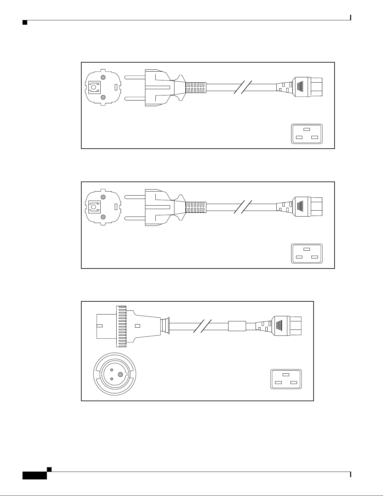
Cordset rating: 16 A, 250 V
Length: 14 ft 0 in. (4.26 m)
Connector: IEC 60320 C19
Plug: CEE 7/7
Cordset rating: 16 A, 250 V
Length: 14 ft 0 in. (4.26 m)
113360
Connector: IEC 60320 C19
Plug: CEE 7/7
Cordset rating: 16 A, 250 V
Length: 14 ft 0 in. (4.26 m)
113361
Connector: IEC 60320 C19
Plug: IEC 309
Figure 1-32 AC Power Cord CAB-2500W-EU=
Figure 1-33 AC Power Cord CAB-AC-2500W-EU=
Chapter 1 Preparing for Installation
1-40
Figure 1-34 AC Power Cord CAB-AC-2500W-INT=
Cisco ASR 9000 Series Aggregation Services Router Hardware Installation Guide
Page 53

Chapter 1 Preparing for Installation
Plug: SI16S3
Cordset rating: 16 A, 250 V
Length: 14 ft 0 in. (4.26 m)
130113
Connector: IEC 60320 C19
Cordset rating: 15 A, 250 V
Length: 14 ft 0 in. (4.26 m)
Connector: IEC 60320 C19
Plug: SAA AS 3112
Cordset rating: 20 A, 250 V
Length: 14 ft 0 in. (4.26 m)
Connector: IEC 60320 C19
Plug: NEMA 6-20
Figure 1-35 AC Power Cord CAB-AC-2500W-ISRL=
Figure 1-36 AC Power Cord CAB-7513ACI=
Site Requirement Guidelines
Figure 1-37 AC Power Cord CAB-AC-2500W-US1=
Cisco ASR 9000 Series Aggregation Services Router Hardware Installation Guide
1-41
Page 54

Site Requirement Guidelines
Cordset rating: 20 A, 250 V
Length: 14 ft 0 in. (4.26 m)
Connector: IEC 60320 C19
Plug: NEMA L6-20
Cord
set rating: 16 A, 250 V
Length: 14 ft 0 in. (4.26 m)
Connector: IEC 60320 C19
Plug: IEC 884
Plug: SEV 5934-2
Type 23
Cordset rating: 16 A, 250 V
Length: 8 ft 2 in. (2.5 m)
113364
Connector: IEC 60320 C19
Figure 1-38 AC Power Cord CAB-AC-C6K-TWLK=
Figure 1-39 AC Power Cord CAB-7513ACSA=
Chapter 1 Preparing for Installation
Cisco ASR 9000 Series Aggregation Services Router Hardware Installation Guide
1-42
Figure 1-40 AC Power Cord CAB-ACS-16=
Page 55
Chapter 1 Preparing for Installation
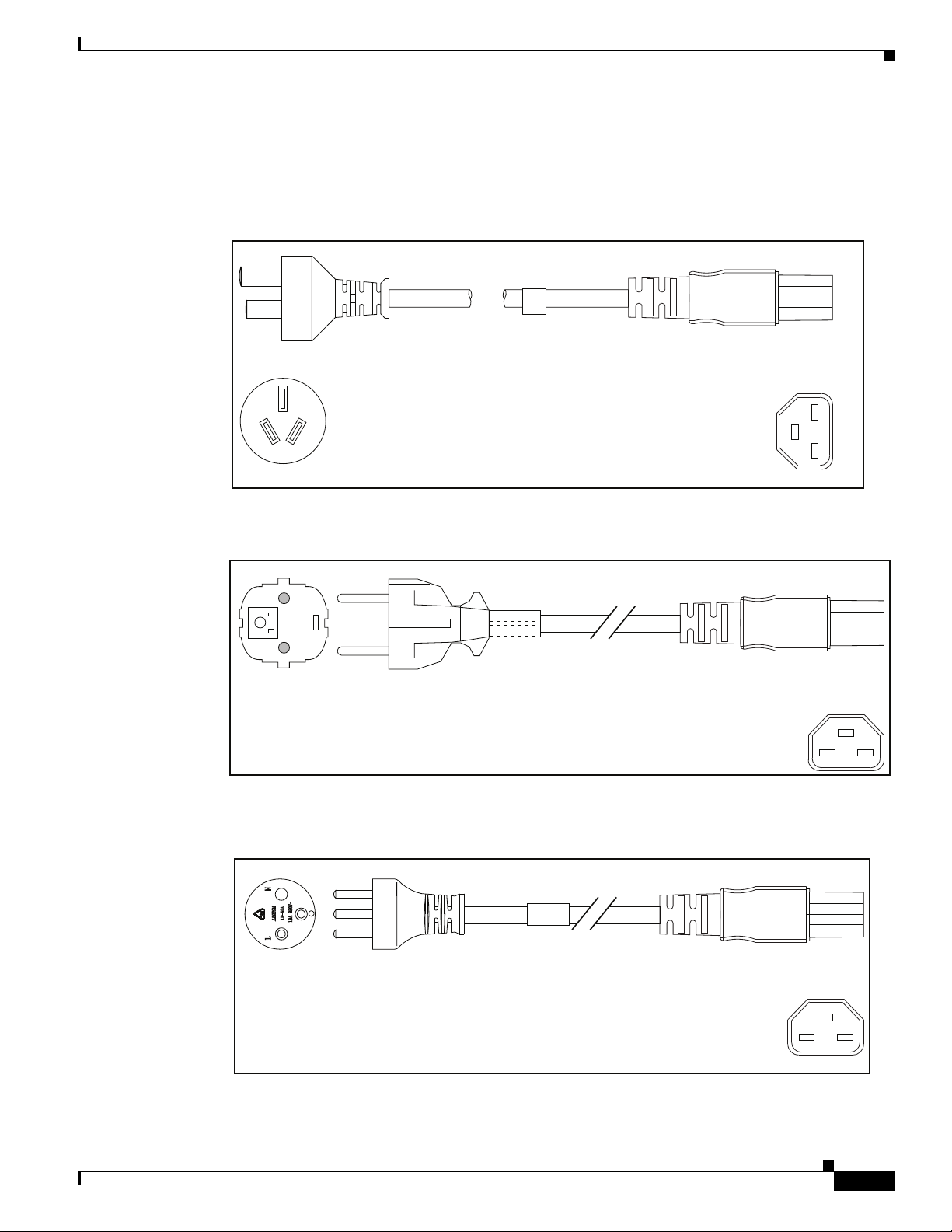
331430
Cordset rating: 16A, 250V
Length: 13.94 ft. (4.25 m)
Plug: GB2099.1/GB1002
Connector: IEC-320-C21
Cordset rating: 16 A, 250 V
Length: 13.94 ft. (4.25 m)
Connector: IEC-320-C21
Plug: CEE 7/7
AC Power Cord Illustrations (Version 2 and Version 3 Power)
This section contains the AC power cord illustrations for version 2 power, as described in Table 1-4.
Figure 1-41 AC Power Cord PWR-CAB-AC-CHN=
Site Requirement Guidelines
Figure 1-42 AC Power Cord PWR-CAB-AC-EU=
Figure 1-43 AC Power Cord PWR-CAB-AC-ISRL=
Cordset rating: 16 A, 250 V
Pl
ug: SI 32
Length: 13.94 ft. (4.25 m)
Connector: IEC-320-C21
Cisco ASR 9000 Series Aggregation Services Router Hardware Installation Guide
331429
1-43
Page 56
Site Requirement Guidelines
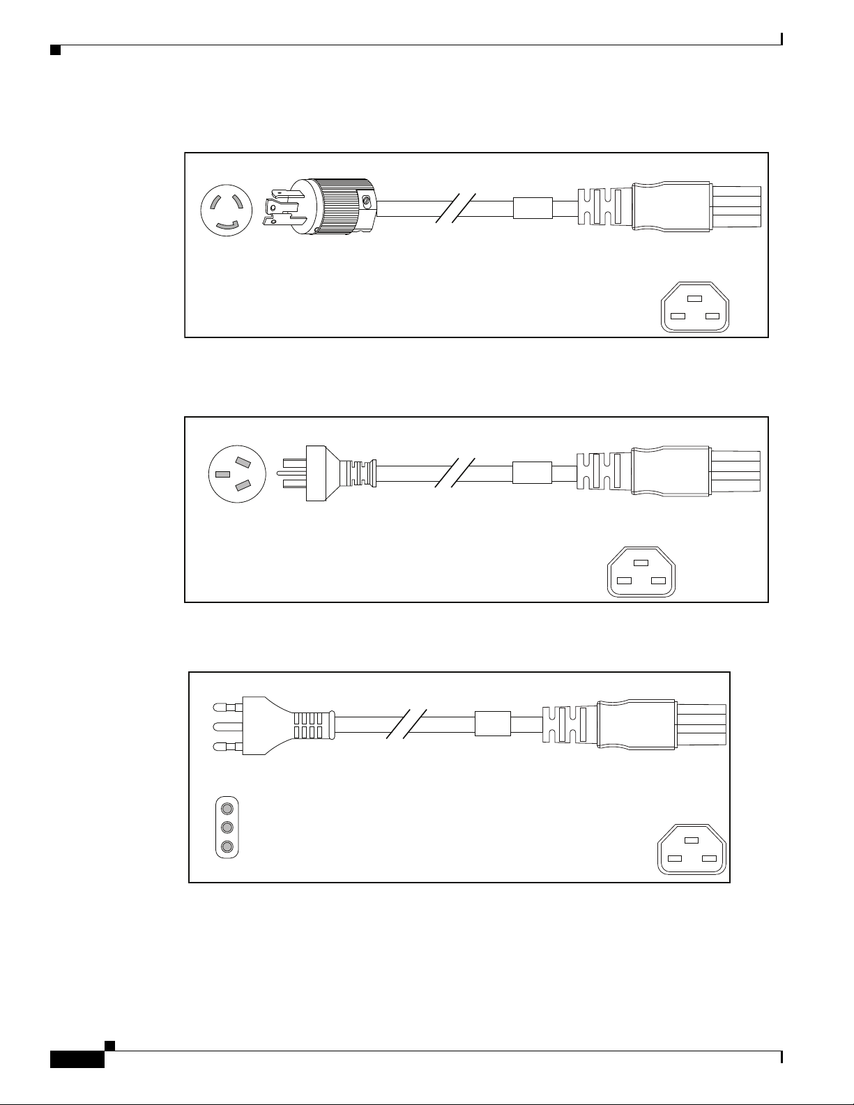
Cordset rating: 20 A, 250 V
Length: 13.94 ft. (4.25 m)
Connector: IEC-320-C21
Plug: NEMA L6-20 P
Cordset rating: 15 A, 250 V
Length: 13.94 ft. (4.25 m)
Connector: IEC-320-C21
Plug: AU20S3
Figure 1-44 AC Power Cord PWR-CAB-AC-USA=
Figure 1-45 AC Power Cord PWR-CAB-AC-AUS=
Chapter 1 Preparing for Installation
Cisco ASR 9000 Series Aggregation Services Router Hardware Installation Guide
1-44
Figure 1-46 AC Power Cord PWR-CAB-AC-ITA=
Cordset rating: 16 A, 250 V
Plug: CEI-23-50
Length: 13.94 ft. (4.25 m)
Connector: IEC-320-C21
331425
Page 57

Chapter 1 Preparing for Installation
Plug: NBR 14136
Cordset rating: 16 A, 250 V
Length: 13.94 ft. (4.25 m)
Connector: IEC-320-C21
331431
Plug: EN-60309-2
Cordset rating: 16 A, 250 V
Length: 13.94 ft. (4.25 m)
Connector: IEC-320-C21
331431
Figure 1-47 AC Power Cord PWR-CAB-AC-BRA=
Figure 1-48 AC Power Cord PWR-CAB-AC-SA=
Site Requirement Guidelines
Cordset rating: 16 A, 250 V
Plug: SABS 164
Length: 13.94 ft. (4.25 m)
Figure 1-49 AC Power Cord PWR-CAB-AC-UK=
Connector: IEC-320-C21
331428
Cisco ASR 9000 Series Aggregation Services Router Hardware Installation Guide
1-45
Page 58

Site Requirement Guidelines
Plug: SEV 5934
Cordset rating: 16 A, 250 V
Length: 13.94 ft. (4.25 m)
Connector: IEC-320-C21
Cordset rating: 20 A, 250 V
Length: 13.94 ft. (4.25 m)
Connector: IEC-320-C21
Plug: JIS C8303
Figure 1-50 AC Power Cord PWR-CAB-AC-SUI=
Figure 1-51 AC Power Cord PWR-CAB-AC-JPN=
Chapter 1 Preparing for Installation
DC-Powered Router
Note A separate ground connection is not required for the version 2 and version 3 power systems. For more
Cisco ASR 9000 Series Aggregation Services Router Hardware Installation Guide
1-46
Connections to DC power modules are rated at 60 A maximum. The system accepts a nominal input voltage
of –48 VDC with an operational tolerance range of –40 VDC to –72 VDC. One dedicated, commensurately
rated DC power source is required for each power module connection.
Power redundancy requirements vary based on the system configuration (number and type of line cards,
etc.). DC-powered systems are N+1 protected. A minimum of two power supplies are required for
redundant operation. Refer to the Cisco ASR 9000 Power Calculator to determine actual redundancy
requirements for any given configuration. See: http://tools.cisco.com/cpc/launch.jsp.
Power connections to the power tray for each DC power module requires four cables: two source cables
and two return cables. In addition, each DC power tray requires one earth ground, so the minimum
number of cables for connecting a single DC power module in a power tray is five (two source, two
return, one ground).
information see NEBS Supplemental Unit Bonding and Grounding Guidelines, page 1-52.
Page 59

Chapter 1 Preparing for Installation
For DC power cables, we recommend that you use 60-A-rated, high-strand-count copper wire cables.The
length of the cables depends on your router location from the source power. DC power cables are not
available from Cisco, but they are available from any commercial cable vendor.
You must terminate DC power cables using cable lugs at the power tray end. Ensure that the lugs are
dual-hole and that they fit over M6 terminal studs at 0.625-inch (15.88-mm) centers. For #4 AWG cable,
use Panduit part number LCD4-14AF-L or equivalent; for #6 AWG, use Panduit part number
LCD6-14AF-L or equivalent.
Site Requirement Guidelines
Warning
Warning
Note Before connecting DC power cords to the power system, make sure that the input power cords are not
Hazardous voltage or energy may be present on power terminals. Always replace cover when
terminals are not in service. Be sure uninsulated conductors are not accessible when cover is in
place.
Statement 1086
Only trained and qualified personnel should be allowed to install, replace, or service this equipment.
Statement 1030
energized.
Note Ensure that there is a readily accessible disconnect device incorporated in the building’s installation
wiring.
Note Circuit breaker and fuse lockout procedures should follow the rules and regulations in the National
Electrical Code (NEC) and any local codes.
Cisco ASR 9000 Series Aggregation Services Router Hardware Installation Guide
1-47
Page 60

Site Requirement Guidelines
Figure 1-52 shows the lug type required for DC input cable connections.
Figure 1-52 Typical DC Power Cable Lug
.25 in +/- .04 in
(6.35 mm +/- 1.016 mm)
Chapter 1 Preparing for Installation
0.63 in +/- .02 in
(16 mm +/- 0.508 mm)
0.48 in +/- .04 in
(12.192 mm +/- 1.016 mm)
(6.858 mm +/- .508 mm)
0.08 in +/- .01 in
(2.032 mm +/- 0.254 mm)
0.27 in +/- .02 in
90 degrees +/- 5 degrees
0.22 in
(5.588 mm)
0.31 in
(7.874 mm)
Beveled wire entry
0.81 in +/- .04 in
(20.574 mm +/- 1.016 mm)
1.16 in
(29.464 mm)
1-48
1.25 in +/- .04 in
(31.75 mm +/- 1.016 mm)
1.66 in (42.164 mm )
Figure 1-53 shows typical DC power source cable connections for a version 1 single DC power
•
243275
module, in this case, a module installed in slot M2 of the power tray.
• Figure 1-54 shows typical DC power source cable connections for a version 2 single DC power
module, in this case, a module installed in slot M3 of the power tray.
• Figure 1-55 shows the plastic safety cover for the version 2 and version 3 DC power tray connection
terminals.
• Figure 1-56 shows typical DC power source cable connections for a version 3 single DC power
module, in this case, a module installed in slot M3 of the power tray.
Note The DC power trays and power modules for the Cisco ASR 9000 Series Routers are identical, so the
examples shown in Figure 1-53, Figure 1-54, Figure 1-55 and Figure 1-55 apply to all of these routers.
Cisco ASR 9000 Series Aggregation Services Router Hardware Installation Guide
Page 61

Chapter 1 Preparing for Installation
Site Requirement Guidelines
Warning
To avoid shock hazard, be sure to apply shrink wrap tubing around the wire entry area of the lug.
Figure 1-53 Typical Source DC Power Cabling Scheme for a Single DC Power Module—Version 1 Power System
243183
PWR A–
–48/60V PWR
Feed A, Slot M2
RTN A+
–48/60V RTN
PWR B–
–48/60V PWR
Feed B, Slot M2
RTN B+
–48/60V RTN
Ground
Cisco ASR 9000 Series Aggregation Services Router Hardware Installation Guide
1-49
Page 62

Chapter 1 Preparing for Installation
Site Requirement Guidelines
Figure 1-54 Typical Source DC Power Cabling Scheme for a Single DC Power Module—Version 2 Power System
M3
M2
M1
M3
M2
M1
344255
PWR A–
–48/60V PWR
RTN A+
–48/60V RTN
PWR B–
Feed A, Slot M3
–48/60V PWR
RTN B+
–48/60V RTN
Feed B, Slot M3
Figure 1-55 Typical Plastic Safety Cover over the Power Tray Connection Terminals—Version 2 and Version 3 Power
System
344357
1-50
Cisco ASR 9000 Series Aggregation Services Router Hardware Installation Guide
Page 63

Chapter 1 Preparing for Installation
Site Requirement Guidelines
Figure 1-56 Typical Source DC Power Cabling Scheme for a Single DC Power Module—Version 3 Power System
PWR A–
–48/60V PWR
Feed A, Slot M3
RTN A+
–48/60V RTN
PWR B–
–48/60V PWR
–48/60V RTN
RTN B+
Feed B, Slot M3
364234
Note A separate ground connection is not required for the version 2 or version 3 power systems. For more
information see the NEBS Supplemental Unit Bonding and Grounding Guidelines, page 1-52.
The color coding of source DC power cable leads depends on the color coding of the site DC power
source. Because there is no color code standard for source DC wiring, be sure that power source cables
are connected to the power modules using the proper positive (+) and negative (–) polarity:
• In some cases, the source DC cable leads might have a positive (+) or a negative (–) label. This is a
relatively safe indication of the polarity, but you must verify the polarity by measuring the voltage
between the DC cable leads. Be sure that the positive (+) and negative (–) cable leads match the
positive (+) and negative (–) labels on the power module when making the measurement.
• Green (or green and yellow) cable typically indicates that it is a ground cable.
Caution DC power modules contain reverse voltage protection circuitry to prevent damage to the power module
if it detects a reverse polarity condition. No damage should occur from reverse polarity, but you should
correct a reverse polarity condition immediately.
For a list of the nominal and acceptable value ranges for source DC power, see “Appendix A.”
Cisco ASR 9000 Series Aggregation Services Router Hardware Installation Guide
1-51
Page 64
Chapter 1 Preparing for Installation
243182
1 2 3
Site Requirement Guidelines
NEBS Supplemental Unit Bonding and Grounding Guidelines
Although the router chassis requires a safety earth ground connection as part of the power cabling to
power modules, you must permanently connect the central office ground system or interior equipment
grounding system to one of the three supplemental bonding and grounding connections on the back or
side of the router chassis to meet Network Equipment Building System (NEBS) requirements as well as
safety compliance requirements. These grounding points are referred to as the NEBS bonding and
grounding points.
Note These bonding and grounding connections satisfy the Telcordia NEBS requirements for supplemental
bonding and grounding connections. If you are not installing the router in a NEBS environment, you can
choose to bypass these guidelines and rely on the safety earth ground connections to the AC or DC power
modules.
Figure 1-57 NEBS Bonding and Grounding Points on the Cisco ASR 9006 Router Chassis
1-52
1 NEBS grounding point on
right side of the chassis
Cisco ASR 9000 Series Aggregation Services Router Hardware Installation Guide
2 NEBS grounding point on
rear of the chassis
3 NEBS grounding point on
left side of the chassis
Page 65

Chapter 1 Preparing for Installation
243373
2 31
1
2
390155
Figure 1-58 NEBS Bonding and Grounding Point on the Cisco ASR 9006 Router Chassis
Site Requirement Guidelines
1 NEBS grounding point on right
side of chassis
Figure 1-59 NEBS Bonding and Grounding Point on the Cisco ASR 9904 Router Chassis
2 NEBS grounding point on rear
of the chassis
3 NEBS grounding point on left
side of the chassis
1 NEBS grounding point on right side of chassis 2 NEBS grounding point on rear of the chassis
Cisco ASR 9000 Series Aggregation Services Router Hardware Installation Guide
1-53
Page 66
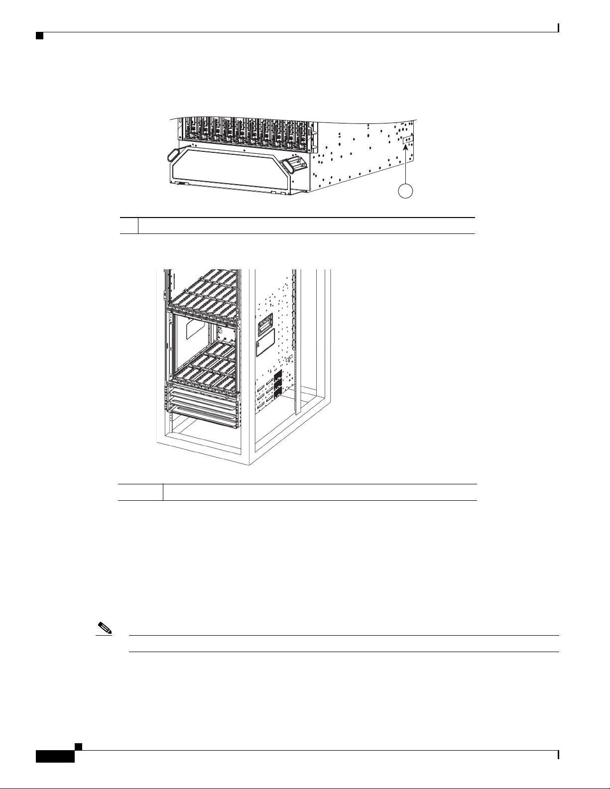
Site Requirement Guidelines
344078
1
303660
Figure 1-60 NEBS Bonding and Grounding Point on the Cisco ASR 9912 Router
1 NEBS grounding point near bottom, rear, right side of the chassis
Figure 1-61 NEBS Bonding and Grounding Point on the Cisco ASR 9922 Router
Chapter 1 Preparing for Installation
1-54
1 NEBS grounding point near bottom, rear, right side of the chassis
To ensure a satisfactory supplemental ground connection to the router, use the following parts:
• One grounding lug, which has two M6 bolt holes with 0.625- to 0.75-inch (15.86- to 19.05-mm)
spacing between them, and a wire receptacle able to accept a 2-6 AWG or larger, multistrand copper
wire. This lug is similar to those used for the DC input power supply leads (Figure 1-52).
• Two 10-32 round-head screws and two locking washers (nickel-plated brass is ideal).
• One grounding wire. Although we recommend at least 2-6 AWG multistrand copper wire, the wire
diameter and length depend on your router location and site environment.
Note These parts are not available from Cisco, but they are available from commercial vendors.
Cisco ASR 9000 Series Aggregation Services Router Hardware Installation Guide
Page 67
Chapter 1 Preparing for Installation
RSP and RP Port Connection Guidelines
This section contains detailed cabling and signal information for interface and port connections to the
Route System Processor (RSP) or Route Processor (RP) cards. It also provides information for Ethernet
routing and equipment.
Note The generic term RSP card refers to the RSP-440, RSP-440 Lite, and RSP-880 cards, unless otherwise
specified.
Caution Ports labeled Ethernet, SYNC, CONSOLE, and AUX are safety extra-low voltage (SELV) circuits. SELV
circuits should only be connected to other SELV circuits.
Console Port and Auxiliary Port Connection Guidelines
Each RSP/RP card has two EIA/TIA-232 (formerly RS232) serial RJ-45 connection ports:
• Console port—RJ-45 interface for connecting a data terminal device to the router, which you need
to perform the initial configuration of the router.
RSP and RP Port Connection Guidelines
• Auxiliary port—RJ-45 interface for connecting a modem.
Note The console and auxiliary ports are asynchronous serial ports. Ensure that devices connected to
these ports are capable of asynchronous transmission.
For the console and auxiliary port locations, see Route Processor Overview, page 4-19.
Cisco ASR 9000 Series Aggregation Services Router Hardware Installation Guide
1-55
Page 68
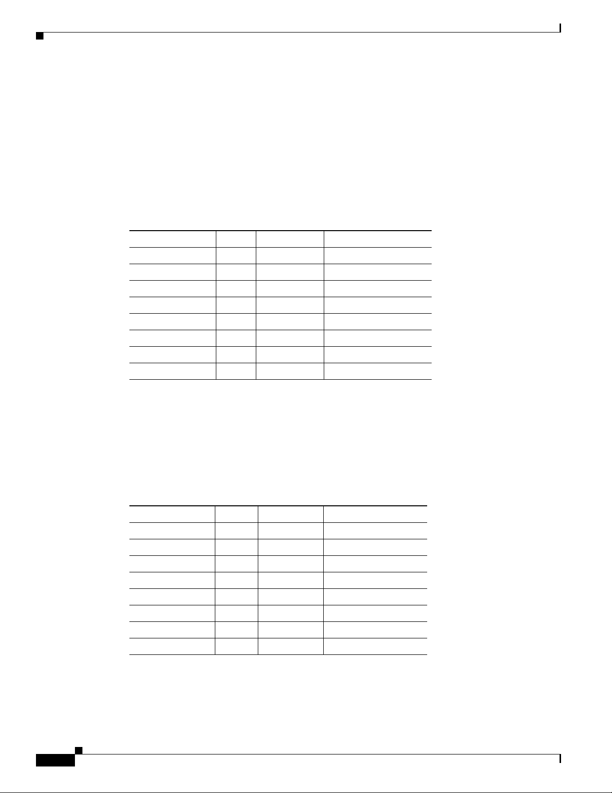
RSP and RP Port Connection Guidelines
Console Port Signals
The console port is an RJ-45 interface for connecting a terminal to the router. The console port does not
support modem control or hardware flow control and requires a straight-through RJ-45 cable.
Before connecting a terminal to the console port, check the terminal setting for the data transmission
rate, in bits per second (bps). The terminal transmission rate setting must match the default rate of the
console port, which is 9600 bps. Set the terminal to these operational values: 9600 bps, 8 data bits, no
parity, 2 stop bits (9600 8N2).
Table 1-5 lists the signals used on the console port.
Table 1-5 RSP/RP Console Port Signals
Console Port Pin Signal Input/Output Description
Chapter 1 Preparing for Installation
1—— —
2 DTR Output Data Terminal Ready
3 TxD Output Transmit data
4 GND — Signal ground
5 GND — Signal ground
6 RxD Input Receive data
7 DSR Input Data Set Ready
8—— —
Auxiliary Port Signals
The Auxiliary (AUX) port is an RJ-45 interface for connecting a modem or other data communication
equipment (DCE) device (such as another router) to the RSP/RP. The AUX port supports hardware flow
control and modem control.
Table 1-6 lists the signals used on the auxiliary port.
Table 1-6 RSP/RP AUX Port Signals
AUX Port Pin Signal Input/Output Description
1 RTS Output Request to send
2 DTR Output Data terminal ready
3 TxD Output Transmit data
4 GND — Signal ground
5 GND — Signal ground
6 RxD Input Receive data
7 DSR Input Data set ready
8 CTS Input Clear to send
1-56
Cisco ASR 9000 Series Aggregation Services Router Hardware Installation Guide
Page 69
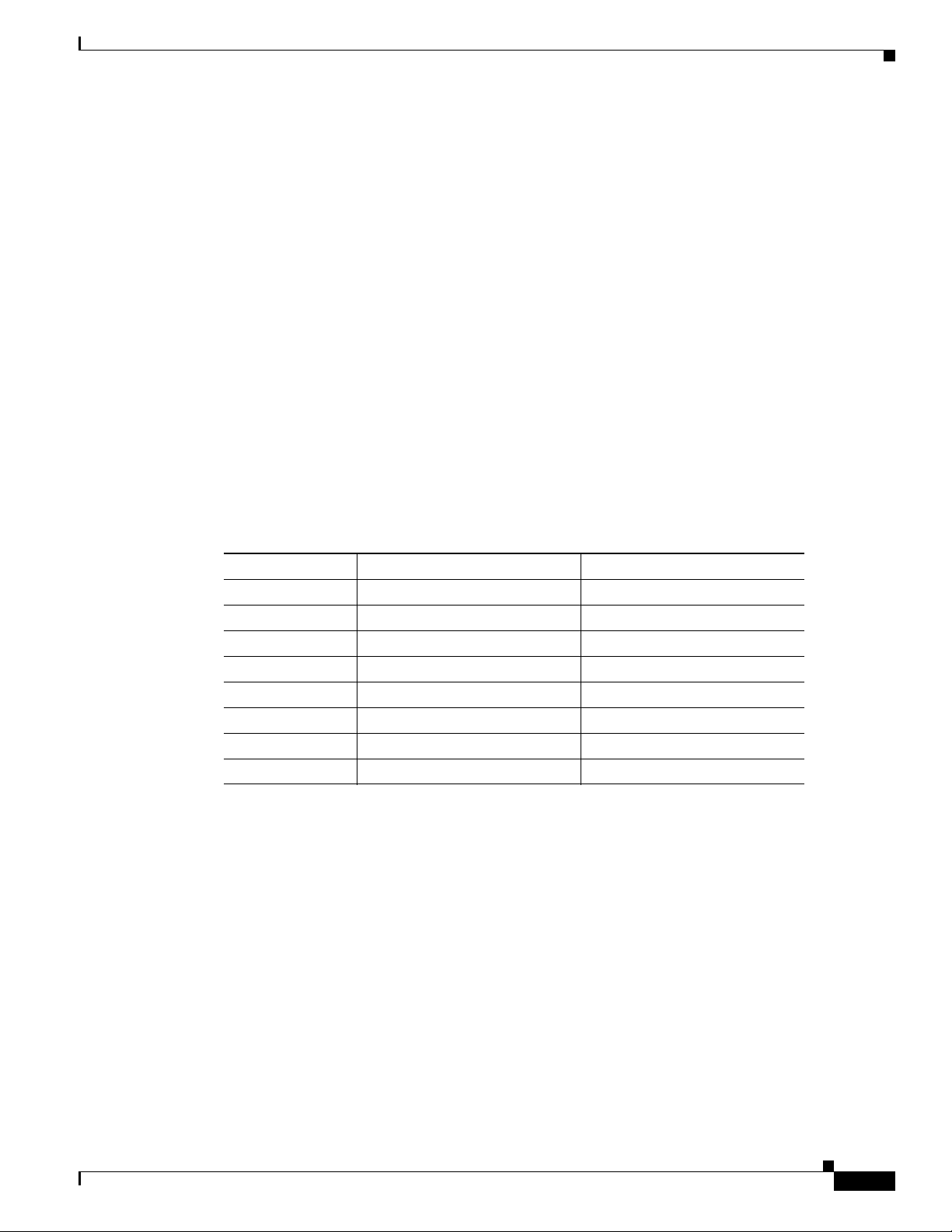
Chapter 1 Preparing for Installation
Management LAN Ports Connection Guidelines
Each RSP/RP card has two RJ-45 media-dependent interface (MDI) Ethernet management LAN ports:
MGT LAN 0 and MGT LAN 1. These ports are used for IEEE 802.3u 100BASE-TX (100 Mbps), or
1000BASE-T (1000 Mbps) Ethernet connections. For the management port locations, see Route
Processor Overview, page 4-19.
The transmission speed of the management LAN ports is not user-configurable. The transmission speed
is set through an autosensing scheme on the RSP/RP; the speed is determined by the network that the
Ethernet port is connected to. The combined total input rate of both MGT LAN 0 and MGT LAN 1 is
about 12 Mbps.
Management port characteristics are:
• Maximum transmission unit (MTU) is fixed at 1514 and cannot be configured.
• Flow control is disabled and cannot be configured.
• Input unicast packets with an unknown destination address are filtered and dropped.
• Autonegotiation of port speed (100/1000) and duplex (full/half) is supported. Autonegotiation
cannot be disabled.
RSP and RP Port Connection Guidelines
Table 1-7 lists the signals used on the Management LAN ports.
Table 1-7 RSP/RP Management LAN Port Signals
MGT LAN Port Pin 100Base-TX Signal 1000Base-T Signal
1 Transmit+ BI_DA+
2 Transmit– BI_DA–
3 Receive+ BI_DB+
4 Unused BI_DC+
5 Unused BI_DC–
6 Receive– BI_DB–
7 Unused BI_DD+
8 Unused BI_DD–
Management LAN Port LED Indicators
The Management LAN connectors have integral LED indicators (Figure 1-62). When lit, these LEDs
indicate:
• Green (LINK)—Connection is alive.
• Amber (ACT)—Connection is active.
Cisco ASR 9000 Series Aggregation Services Router Hardware Installation Guide
1-57
Page 70
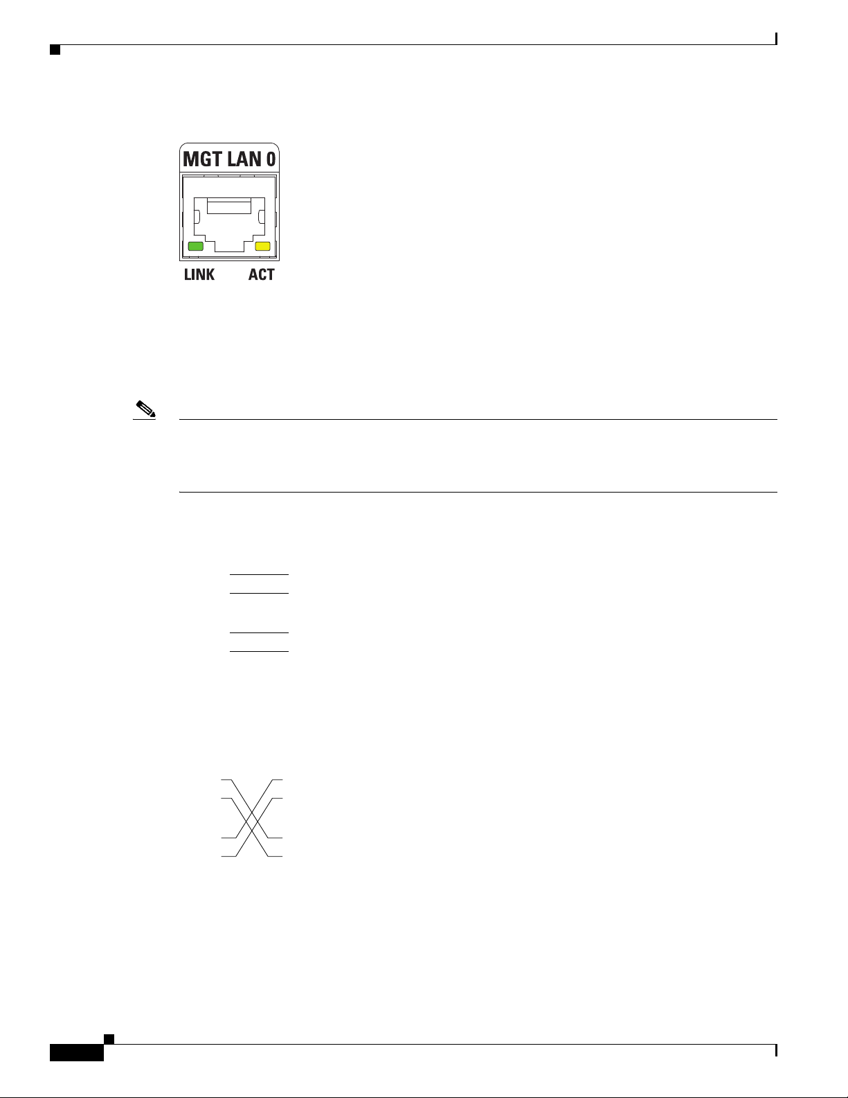
RSP and RP Port Connection Guidelines
MDI-X wiringMDI wiring
1 TxD+
2 TxD–
3 RxD+
6 RxD–
1 RxD+
2 RxD–
3 TxD+
6 TxD–
H11007
PRP
1 TxD+
2 TxD–
3 RxD+
6 RxD–
1 TxD+
2 TxD–
3 RxD+
6 RxD–
75431
PRP
Figure 1-62 RSP/RP Management LAN Port LED Indicators
Management LAN RJ-45 Cabling
When connecting the RJ-45 port to a hub, repeater, or switch, use the straight-through cable pinout as
shown in Figure 1-63.
Note To comply with the intrabuilding lightning surge requirements of Telecordia GR-1089-CORE, Issue II,
Revision 01, February 1999, you must use a shielded cable when connecting to the management LAN
ports on the RSP/RP card. The shielded cable is terminated by shielded connectors on both ends, with
the cable shield material tied to both connectors.
Chapter 1 Preparing for Installation
Figure 1-63 Straight-Through Cable Pinout to a Hub, Repeater or Switch
When connecting the RJ-45 port to a router, use the crossover cable pinout as shown in Figure 1-64.
Figure 1-64 Crossover Cable Pinout Between RSPs/RPs
1-58
Cisco ASR 9000 Series Aggregation Services Router Hardware Installation Guide
Page 71
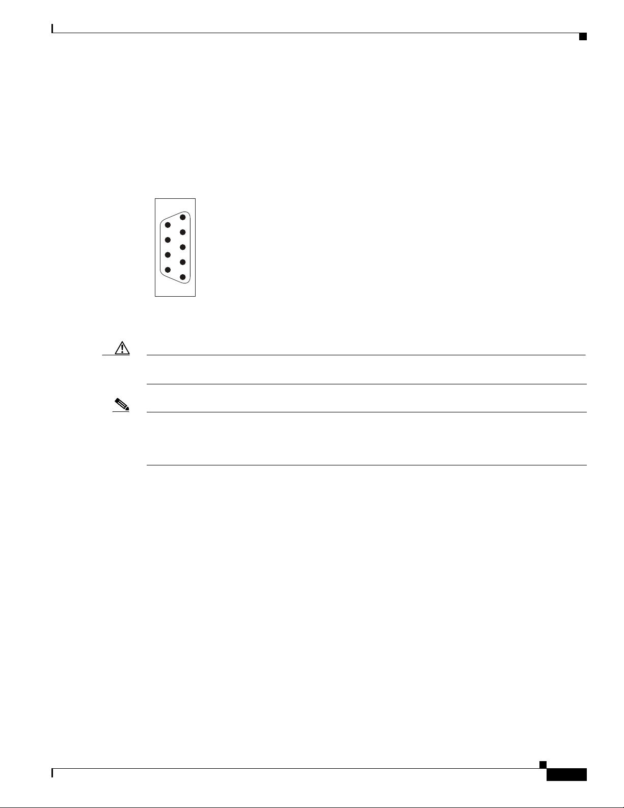
Chapter 1 Preparing for Installation
243085
5
4
3
2
1
9
8
7
6
Alarm Connection Guidelines
The RSP/RP card has an alarm connector on its front panel. This 9-pin D-subconnectors (ALARM OUT)
connects the router to an external site alarm maintenance system (Figure 1-65). When a critical, major,
or minor alarm is generated, it energizes the alarm relays on the RSP/RP card to activate the external site
alarm.
Figure 1-65 Alarm Connector on the RSP/RP Card Front Panel
The alarm relay contacts on the RSP/RP card consist of standard common, normally open, and normally
closed relay contacts that are wired to the pins on the connectors.
RSP and RP Port Connection Guidelines
Caution Only safety extra-low voltage (SELV) circuits can be connected to the alarm connector. Maximum rating
for the alarm circuit is 100 mA, 50 V.
Note To comply with the intrabuilding lightning surge requirements of Telecordia GR-1089-CORE, Issue II,
Revision 01, February 1999, you must use a shielded cable when connecting to the external alarm port
on the RSP/RP card. The shielded cable is terminated by shielded connectors on both ends, with the
cable shield material tied to both connectors.
Cisco ASR 9000 Series Aggregation Services Router Hardware Installation Guide
1-59
Page 72
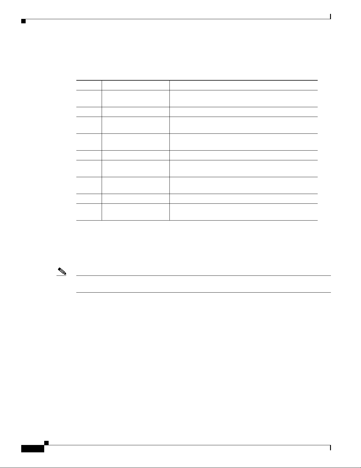
RSP and RP Port Connection Guidelines
Table 1-8 lists the pin-to-signal correspondence between the cable connector pins and the alarm
connector relay contacts.
Table 1-8 Alarm Connector Pinout
Pin Signal Note
1 Critical alarm NC NC (normally closed) connected to CM (common) when
2 Critical alarm CM Common
3 Critical alarm NO NO (normally open) connected to CM (common) during a
4 Major alarm NC NC (normally closed) connected to CM (common) when
5 Major alarm CM Common
6 Major alarm NO NO (normally open) connected to CM (common) during a
7 Minor alarm NC NC (normally closed) connected to CM (common) when
8 Minor alarm CM Common
9 Minor alarm NO NO (normally open) connected to CM (common) during a
Chapter 1 Preparing for Installation
there is no Critical alarm
Critical alarm
there is no Major alarm
Major alarm
there is no Minor alarm
Minor alarm
Sync Port Connection Guidelines
The SYNC 0 and SYNC 1 ports are timing synchronization ports. They can be configured as Building
Integrated Timing Supply (BITS) ports or J.211 ports (Figure 1-66).
Note Both ports must be configured to be the same mode. It is not possible to use external BITS and J.211
sources at the same time.
When configured as BITS ports, they provide connections for an external synchronization source for
establishing precise frequency control at multiple network nodes, if required for your application. The
RSP/RP card contains a synchronous equipment timing source (SETS) that can receive a frequency
reference from an external BITS timing interface or from a clock signal recovered from any incoming
Gigabit Ethernet or 10-Gigabit Ethernet interface. The RSP/RP SETS circuit filters the received timing
signal and uses it to drive outgoing Ethernet interfaces.
The BITS input can be T1, E1 or 64K 4/. The BITS output can be T1, E1 or 6.312M 5/.
When configured as J.211 ports, they can be used as Universal Timing Interface (UTI) ports to
synchronize timing across multiple routers by connecting to an external timing source.
When lit, these LEDs indicate for BITS:
• Green (LINK)—Connection is alive.
• Amber (FAULT)—A fault has occurred.
1-60
Cisco ASR 9000 Series Aggregation Services Router Hardware Installation Guide
Page 73

Chapter 1 Preparing for Installation
When lit, these LEDs indicate for UTI:
• Green (NORMAL)—UTI is operating in normal mode.
• Amber (FAST)—UTI is operating in fast mode.
Figure 1-66 SYNC Port Connector
Table 1-9 BITS/J.211 Connector Pinout
Pin Signal Note
1 DTI_P/BITS_RX_P Bi-direction for DTI, T1/E1/64K Input
2 DTI_P/BITS_RX_N Bi-direction for DTI, T1/E1/64K Input
3— —
4 BITS_TX_P* T1/E1/6.321M Output
5 BITS_TX_N* T1/E1/6.321M Output
6— —
7— —
8 — —
RSP and RP Port Connection Guidelines
12345678
243166
SFP/SFP+ Port
The RSP-440 and RSP-440 Lite support two 10-GE Small Form-Factor Pluggable Plus (SFP+)
virtualization cluster ports. The RSP-880 supports four 10-GE SFP+ ports that are used for external
server connectivity capability.
GPS Interface
The RSP-440, RSP-440 Lite, and RSP-880 have a Time of Day (ToD) port, 10-MHz connector, and
1-PPS connector that allow you to configure input or output clocking with a GPS device.
Inter Chassis Synchronization Port
The nV Sync 0 and nV Sync 1 ports on the RSP-440, RSP-440 Lite, and RSP-880 are the RJ-45
inter-chassis synchronization clock interfaces for synchronizing frequency and time.
Cisco ASR 9000 Series Aggregation Services Router Hardware Installation Guide
1-61
Page 74

RSP and RP Port Connection Guidelines
CMP Port
The Connectivity Management Processor (CMP) on the RSP-440, RSP-440 Lite, and RSP-880 card, is
a secondary, lightweight processor that provides a second network interface to the system. Each CMP
contains its own RAM, bootflash, and front panel management Ethernet port.
The CMP port provides the following functions:
• RSP4 ROMMON console access through the CMP port. This eliminates the need to use external
terminal servers.
• SSH/telnet into a designated CMP port.
RSP Compact Flash Slot
The Cisco ASR 9000 Series Router RSP cards support a single ATA/IDE type I/II compact flash external
slot accessible on the front panel. The compact flash slot has a door that can be closed whether a compact
flash device is present or not. The file systems supported on compact flash are DOS/FAT or QNX4. The
compact flash comes with a DOS format. The supported flash disk sizes and their Cisco part numbers
are listed in Table 4-5.
Chapter 1 Preparing for Installation
USB Port
The RSP-440, RSP-440 Lite, and RSP-880 cards do not have an ATA/IDE type I/II compact flash external
slot.
The RSP-440, RSP-440 Lite, RSP-880, and Cisco ASR 9922 Router RP cards have a single external
Universal Serial Bus (USB) port. A USB flash memory device can be inserted to load and transfer
software images and files. This memory device can be used to turboboot the system or as the installation
source for Package Information Envelopes (PIE) and Software Maintenance Upgrades (SMU). This
memory device can also be used for users' data files, core files, and configuration backups.
1-62
Cisco ASR 9000 Series Aggregation Services Router Hardware Installation Guide
Page 75

CHA P T ER
Unpacking and Installing the Chassis
This chapter describes how to unpack and install the chassis into a rack.
• Pre-Installation Considerations and Requirements, page 2-1
• Installation Overview, page 2-2
• Unpacking the Router, page 2-3
• Removing Components Before Installing the Chassis, page 2-18
• Rack-Mounting the Router Chassis, page 2-42
• Supplemental Bonding and Grounding Connections, page 2-56
• Installing Chassis Accessories, page 2-61
Pre-Installation Considerations and Requirements
2
Before you perform any procedures in this chapter, review the following sections:
• Safety Guidelines, page 1-1
• Site Requirement Guidelines, page 1-8
Observe the guidelines for preventing electrostatic discharge (ESD) damage described in the “Preventing
Electrostatic Discharge Damage” section on page 1-2.
See the Regulatory Compliance and Safety Information for the Cisco ASR 9000 Series Router document
for additional safety and compliance information,
Caution This router is not designed to be installed as a shelf-mounted or a free-standing router. The router must
be installed in a rack that is secured to the building structure. You must install the router in either a
telco-style frame or a 4-post equipment rack.
Cisco ASR 9000 Series Aggregation Services Router Hardware Installation Guide
2-1
Page 76

Installation Overview
243355
Installation Overview
Figure 2-1 shows how the Cisco ASR 9010 Router is shipped and strapped to a shipping pallet.
Figure 2-1 Cisco ASR 9010 Router Packaged on a Shipping Pallet
Chapter 2 Unpacking and Installing the Chassis
2-2
A fully equipped router with six power modules can weigh as much as 375 lbs (170.5 kg); an empty
chassis weighs 150 lbs (67.8 kg). The chassis is designed to be lifted by two persons after you remove
some of the components, such as line cards, power supplies, and the fan tray, to reduce the weight before
lifting the chassis. See Removing Components Before Installing the Chassis, page 2-18 for procedures
to remove these components.
Cisco ASR 9000 Series Aggregation Services Router Hardware Installation Guide
Page 77

Chapter 2 Unpacking and Installing the Chassis
Required Tools and Equipment
Before you begin the rack-mount installation, you must read and understand the information in the
Rack-Mounting and Air Flow Clearance Guidelines, page 1-20, and have the following tools and
equipment:
• ESD-preventive wrist strap
• Number 1 and number 2 Phillips screwdrivers
• 1/4-inch (6.35-mm) and 3/16-inch (4.5-mm) flat-blade screwdrivers
• Tape measure
• Level (optional)
• Minimum of 10 slotted binderhead screws (usually provided with the rack) to secure the chassis to
the mounting flanges (also called rails) in the rack. Five screws should be installed on each side of
the chassis.
• 11/16-inch (17.46-mm) wrench (for chassis hold-down bolts and pallet hold-down bracket bolts)
• 3/4-inch (19-mm) socket and ratchet wrench
Unpacking the Router
Unpacking the Router
The following instructions describe how to unpack the Cisco ASR 9000 Series Router from its shipping
container.
• Unpacking the Cisco ASR 9010 Router, page 2-3
• Unpacking the Cisco ASR 9006 Router, page 2-5
• Unpacking the Cisco ASR 9904 Router, page 2-7
• Unpacking the Cisco ASR 9922 Router, page 2-9
• Unpacking the Cisco ASR 9912 Router, page 2-13
Unpacking the Cisco ASR 9010 Router
Follow these steps to unpack the Cisco ASR 9010 Router from its shipping container.
Step 1 Cut the straps that secure the cardboard shipping container to the pallet.
Step 2 Remove the cardboard shipping container.
Step 3 Remove the packaging material (see Figure 2-2).
a. Remove the foam packaging material from the top of the router.
b. Remove all screws that secure the four hold-down brackets to the router chassis. The forward
hold-down brackets are secured to the router mounting brackets by two screws. The rear hold-down
brackets are secured to the chassis by four screws. Save these four screws used to hold the rear
bracket to the chassis to use later to attach the ground strap.
Step 4 Remove two bolts per hold-down bracket that secure the brackets to the pallet.
Cisco ASR 9000 Series Aggregation Services Router Hardware Installation Guide
2-3
Page 78

Unpacking the Router
243356
LINK ACT
MGT LAN 1 CONSOLE 0
BITS J.211
1
ALARM OUT
BITS J.211
MGT LAN 0
ACO
FAIL
CRIT
MAJ
MIN
SYNC
HDD
CF
ACO
LAMP
TEST
LINK ACT
MGT LAN 1 CONSOLE 0
BITS J.211
1
ALARM OUT
BITS J.211
MGT LAN 0
ACO
FAIL
CRIT
MAJ
MIN
SYNC
HDD
CF
ACO
LAMP
TEST
1
2
2
3
Chapter 2 Unpacking and Installing the Chassis
Figure 2-2 Unpacking the Cisco ASR 9010 Router from the Shipping Container and Pallet
1 Foam packaging material-
top cap
2 Front hold-down bracket
secured by two screws to the
chassis mounting brackets,
and by two bolts to the
3 Rear hold-down bracket
secured by four screws to the
chassis, and by two bolts to
the pallet (two places)
pallet (two places)
Step 5
Remove components, such as line cards and the fan tray, to reduce the weight before lifting or moving
the chassis. See the Removing Components Before Installing the Chassis, page 2-18 for more
information.
Step 6 Save the packaging materials in case the router needs repackaging or shipping.
2-4
Cisco ASR 9000 Series Aggregation Services Router Hardware Installation Guide
Page 79

Chapter 2 Unpacking and Installing the Chassis
Unpacking the Cisco ASR 9006 Router
Follow these steps to unpack the Cisco ASR 9006 Router from its shipping container (Figure 2-3).
Step 1 Cut the straps that secure the cardboard shipping container to the pallet.
Step 2 Remove the cardboard shipping container.
Step 3 Remove the packaging material (Figure 2-3).
a. Remove the foam packaging material from the top of the router.
b. Remove all screws that secure the four hold-down brackets to the router chassis. The forward
hold-down brackets are secured to the router mounting brackets by two screws. The rear hold-down
brackets are secured to the chassis by four screws.
c. Remove two bolts per hold-down bracket that secure the brackets to the pallet.
Unpacking the Router
Cisco ASR 9000 Series Aggregation Services Router Hardware Installation Guide
2-5
Page 80
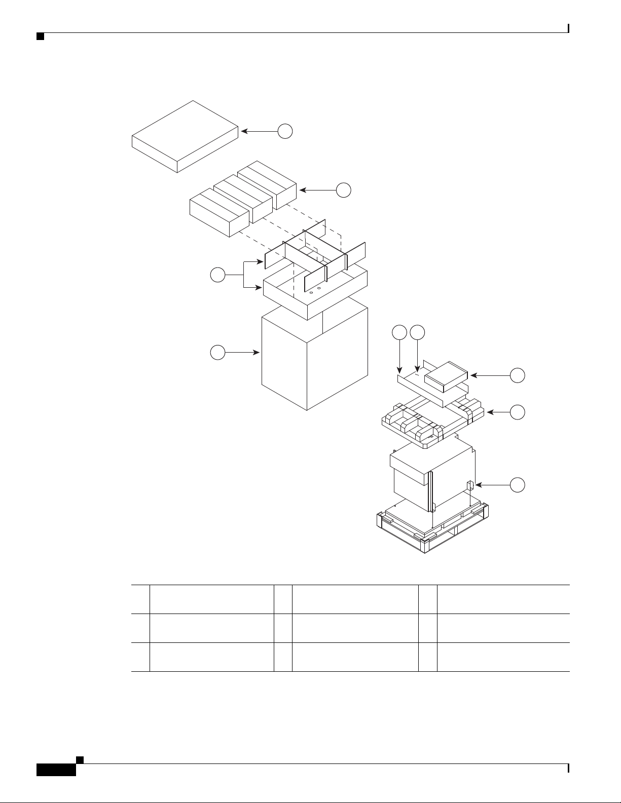
Unpacking the Router
1
2
3
4
7
5 6
8
9
243454
Chapter 2 Unpacking and Installing the Chassis
Figure 2-3 Unpacking the Cisco ASR 9006 Router from the Shipping Container and Pallet
cap
2 Three packaged power
modules
3 Cardboard packaging
dividers
1 Top cardboard packaging
4 Cardboard packaging
7 Chassis accessories
container
5 Cardboard accessory tray 8 Foam packaging material-
top cap
6 Accessories and power
cables
9 Hold-down brackets
(four places)
2-6
Cisco ASR 9000 Series Aggregation Services Router Hardware Installation Guide
Page 81

Chapter 2 Unpacking and Installing the Chassis
Step 4 Remove components, such as line cards, power supplies, and the fan tray, to reduce the weight before
lifting or moving the chassis. See Removing Components Before Installing the Chassis, page 2-18 for
more information.
Step 5 Save the packaging materials in case the router needs repackaging or shipping.
Unpacking the Cisco ASR 9904 Router
Follow these steps to unpack the Cisco ASR 9904 Router from its wooden shipping container.
Step 1 Cut the straps that secure the cardboard shipping container to the pallet.
Step 2 Remove the corrugated top shipping container.
Step 3 Remove the accessories and corrugated packing accessory tray.
Step 4 Remove the packing material (Figure 2-4).
a. Remove the foam packaging material from the top of the router.
b. Remove the plastic covering from the router and remove it from the bottom foam.
Unpacking the Router
Cisco ASR 9000 Series Aggregation Services Router Hardware Installation Guide
2-7
Page 82
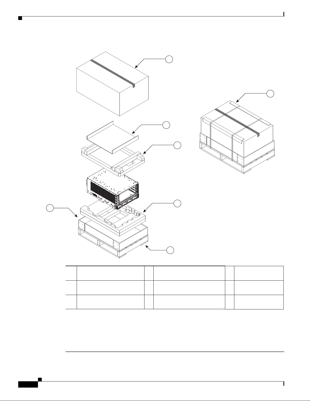
Unpacking the Router
351310
1
7
3
4
5
6
2
Chapter 2 Unpacking and Installing the Chassis
Figure 2-4 Unpacking the Cisco ASR 9904 Router from the Shipping Container and Pallet
1 Shipping pallet 4 Foam packaging material
2 Top corrugated packaging cap 5 Foam packaging material
3 Corrugated packaging
accessory tray
Step 5 Remove components, such as line cards, power supplies, and the fan tray, to reduce the weight before
(top cap)
(bottom cap)
7 Cardboard shipping
container
6 Corrugated packaging
(lower tray)
lifting or moving the chassis. See Removing Components Before Installing the Chassis, page 2-18 for
more information.
Step 6 Save the packaging materials in case the router needs repackaging or shipping.
2-8
Cisco ASR 9000 Series Aggregation Services Router Hardware Installation Guide
Page 83

Chapter 2 Unpacking and Installing the Chassis
302353
Unpacking the Cisco ASR 9922 Router
Follow these steps to unpack the Cisco ASR 9922 Router from its wooden shipping container.
Step 1 Remove any strapping on the outside of the crate.
Step 2 Remove the crate cap door. Disengage the twist locks located along the bottom first. Then, disengage the
twist locks located along the sides, working your way up from the bottom to the top. Refer to the right
and middle figures in Figure 2-5.
Step 3 Remove the crate cap. Disengage the twist locks located around the bottom of the crate cap (Figure 2-5).
Note Two people are required to evenly slide the crate cap back off of the plastic pallet base.
Step 4 Remove the foam packaging material from the top of the router.
Figure 2-5 Unpacking the Cisco ASR 9922 Router from the Shipping Container
Unpacking the Router
Step 5
Using a 5/16” wrench or ratchet, remove the four attachment bolts and cross-brace from the shipping
rack (Figure 2-6).
Cisco ASR 9000 Series Aggregation Services Router Hardware Installation Guide
2-9
Page 84

Unpacking the Router
344358
Chapter 2 Unpacking and Installing the Chassis
Figure 2-6 Cross-brace and Attachment Bolts on the Shipping Rack
2-10
Cisco ASR 9000 Series Aggregation Services Router Hardware Installation Guide
Page 85
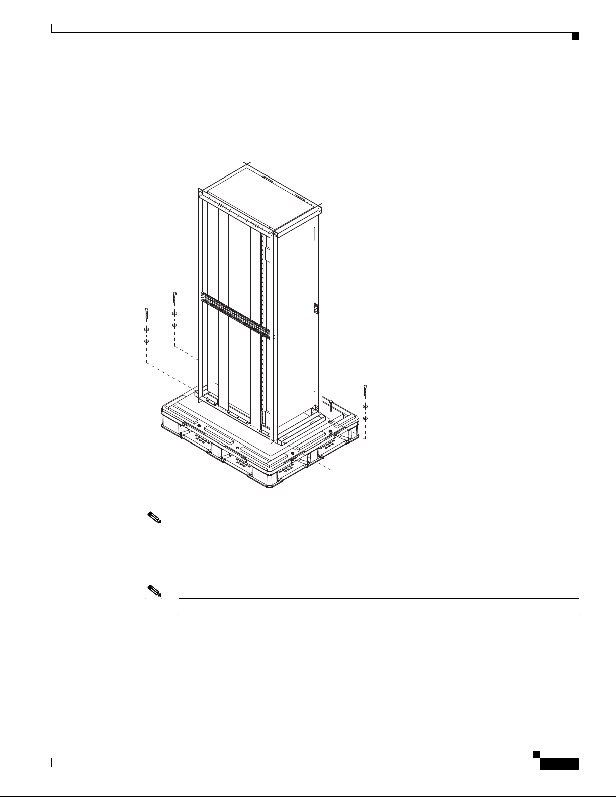
Chapter 2 Unpacking and Installing the Chassis
302355
Step 6 Use a Phillips screwdriver to unscrew the rear mounting flange from the system and rack.
Step 7 Use a Phillips screwdriver to unscrew the front mounting flange from the rack.
Step 8 Remove two bolts per hold-down bracket that secure the brackets to the pallet (Figure 2-7).
Figure 2-7 Hold-Down Brackets on the Cisco ASR 9922 Router Shipping Pallet
Unpacking the Router
Note Do not unbolt the shipping rack from the pallet.
Step 9 Save the rear brackets and screws from the shipping packaging for reuse in rack mounting of the chassis
(Figure 2-8).
Note The two guide rails at the bottom of the rack come in the ASR-9922-ACC-KIT accessory kit.
Cisco ASR 9000 Series Aggregation Services Router Hardware Installation Guide
2-11
Page 86
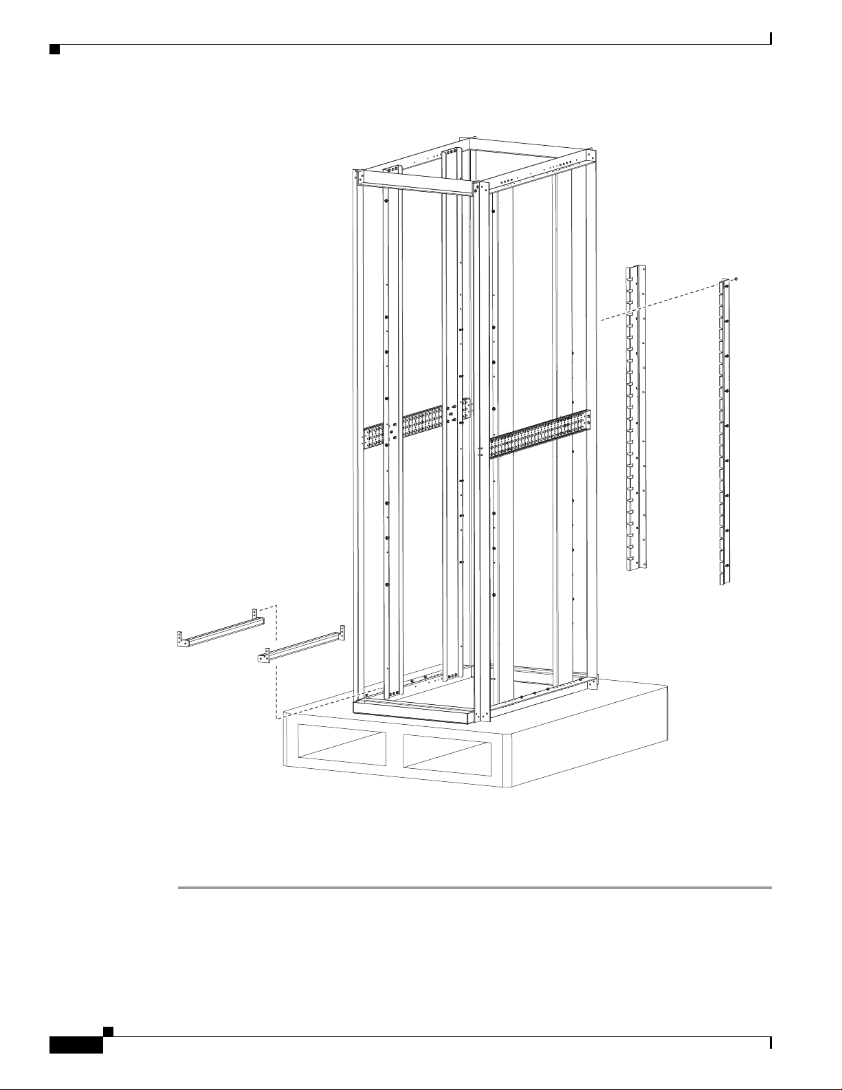
Unpacking the Router
Chapter 2 Unpacking and Installing the Chassis
Figure 2-8 Rack Mount Installation Kit for the Cisco ASR 9922 Router
2-12
Step 10
Remove components, such as line cards and fan trays, to reduce the weight before lifting or moving the
chassis. See Removing Components Before Installing the Chassis, page 2-18 for procedures showing
how to remove these components.
Step 11 Save the packaging materials in case the router needs to be repackaged for shipping.
Cisco ASR 9000 Series Aggregation Services Router Hardware Installation Guide
344377
Page 87
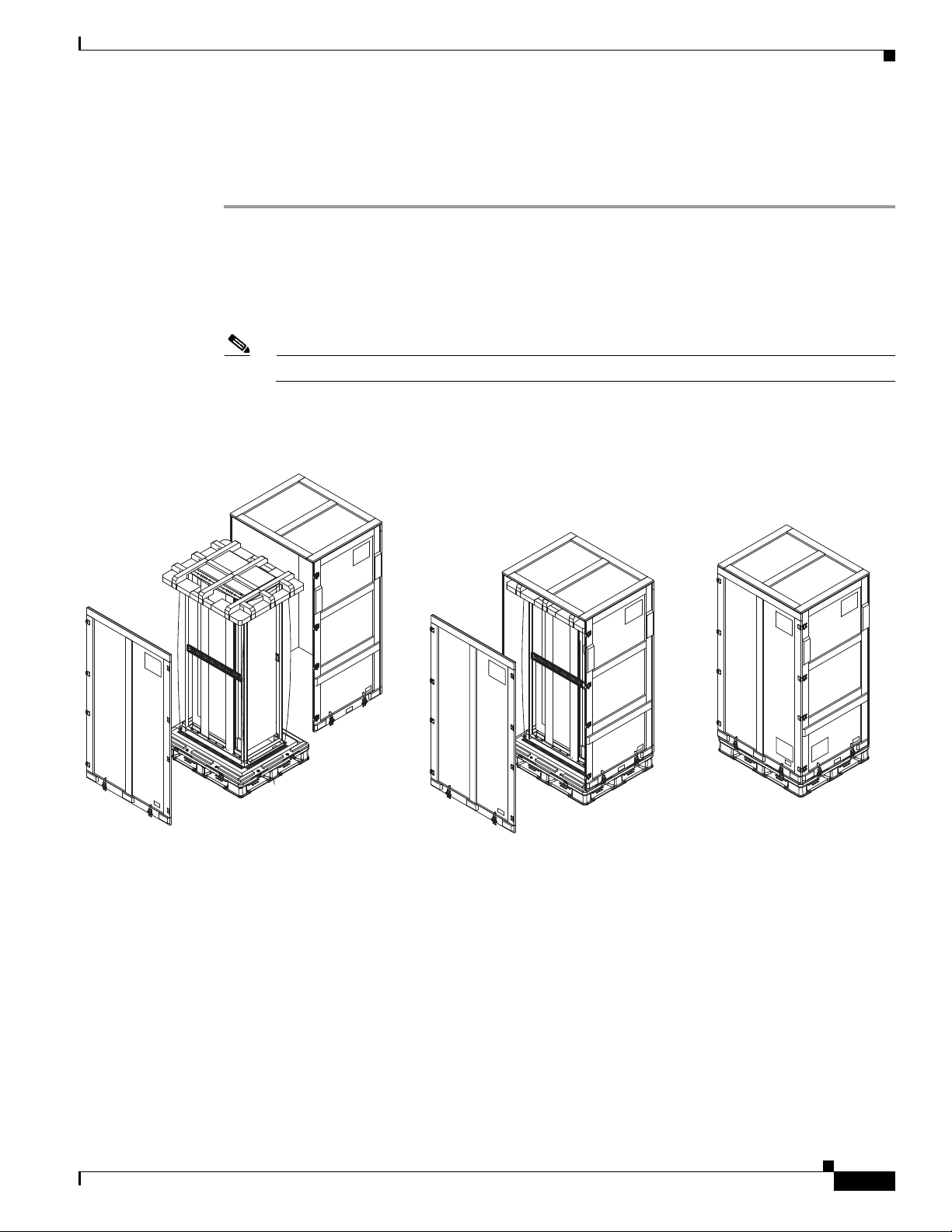
Chapter 2 Unpacking and Installing the Chassis
302353
Unpacking the Cisco ASR 9912 Router
Follow these steps to unpack the Cisco ASR 9912 Router from its wooden shipping container.
Step 1 Remove any strapping on the outside of the crate.
Step 2 Remove the crate cap door. Disengage the twist locks located along the bottom first. Then, disengage the
twist locks located along the sides, working your way up from the bottom to the top. Refer to the right
and middle figures in Figure 2-9.
Step 3 Remove the crate cap. Disengage the twist locks located around the bottom of the crate cap (Figure 2-9).
Note Two people are required to evenly slide the crate cap back off of the plastic pallet base.
Step 4 Remove the foam packaging material from the top of the router.
Figure 2-9 Unpacking the Cisco ASR 9912 Router from the Shipping Container
Unpacking the Router
Step 5
Using a 5/16” wrench or ratchet, remove the four attachment bolts and cross-brace from the shipping
rack (Figure 2-10).
Cisco ASR 9000 Series Aggregation Services Router Hardware Installation Guide
2-13
Page 88
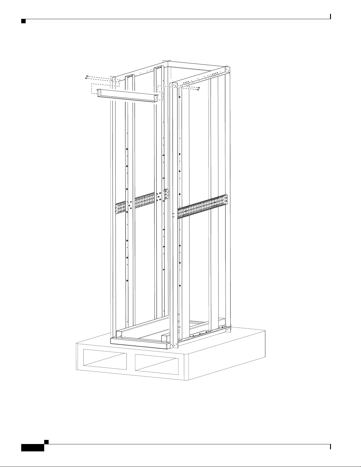
Unpacking the Router
344358
Chapter 2 Unpacking and Installing the Chassis
Figure 2-10 Cross-brace and Attachment Bolts on the Shipping Rack
2-14
Cisco ASR 9000 Series Aggregation Services Router Hardware Installation Guide
Page 89

Chapter 2 Unpacking and Installing the Chassis
302355
Step 6 Use a Phillips screwdriver to unscrew the rear mounting flange from the system and rack.
Step 7 Use a Phillips screwdriver to unscrew the front mounting flange from the rack.
Step 8 Remove two bolts per hold-down bracket that secure the brackets to the pallet (Figure 2-11).
Figure 2-11 Hold-Down Brackets on the Cisco ASR 9912 Router Shipping Pallet
Unpacking the Router
Note Do not unbolt the shipping rack from the pallet.
Step 9 Save the rear brackets and screws from the shipping packaging for reuse in rack mounting of the chassis
(Figure 2-12).
Note The two guide rails at the bottom of the rack come in the ASR-9912-ACC-KIT accessory kit.
Cisco ASR 9000 Series Aggregation Services Router Hardware Installation Guide
2-15
Page 90

Unpacking the Router
Chapter 2 Unpacking and Installing the Chassis
Figure 2-12 Rack Mount Installation Kit for the Cisco ASR 9912 Router
2-16
Step 10
Remove components, such as line cards and fan trays, to reduce the weight before lifting or moving the
chassis. See Removing Components Before Installing the Chassis, page 2-18 for procedures showing
how to remove these components.
Step 11 Save the packaging materials in case the router needs to be repackaged for shipping.
Cisco ASR 9000 Series Aggregation Services Router Hardware Installation Guide
344377
Page 91

Chapter 2 Unpacking and Installing the Chassis
Unpacking the Router
Positioning the Router
Positioning the Cisco ASR 9010 Router, Cisco ASR 9006 Router, and Cisco 9904 Router
Use a safety hand truck to move the Cisco ASR 9010 Router, Cisco ASR 9006 Router, or
Cisco ASR 9904 Router router to its final location for rack installation.
Positioning the and Cisco ASR 9922 Router and Cisco ASR 9912 Router
TheCisco ASR 9922 Router and Cisco ASR 9912 Router and each ship in a carton similar to the CRS-1
16-Slot shipping carton. Each chassis is installed in a shipping rack used only for shipping purposes.
Remove the chassis from the shipping rack before installing it into the rack.
To prepare the 19-inch 45-RU rack:
Step 1 Install the two guide rails onto the bottom of the rack.
The guide rails are included with the ASR-9922-ACC-KIT and ASR-9912-ACC-KIT accessory kits.
Each accessory kit ships with the chassis and includes the guide rails, grounding lug, associated
hardware, and a warranty card.
Step 2 Use screws to fasten these two guide rails onto the front and rear rails of the rack.
The two guide rails at the bottom of the rack (Figure 2-8) have six holes (three per rail) that
accommodate 12-24 or M6 screws. If you are using smaller 10-32 screws, you must use bushings to fit
the larger holes (Figure 2-13).
Figure 2-13 One 10-32 Screw with Bushings in Guide Rail Holes
303498
Note Delrin bushings with part number 17234-D-1 can be obtained from ASM at
www.accuratescrew.com.
Step 3 Remove the shipping carton, plastic covering, rear brackets, attachment screws and bolts, shipping rack
bar, and any cosmetic accessories included with the chassis.
Cisco ASR 9000 Series Aggregation Services Router Hardware Installation Guide
2-17
Page 92

Removing Components Before Installing the Chassis
Step 4 Use a scissors jack to remove the chassis from the shipping rack. Place a pallet jack next to the chassis
inside the shipping rack and push/pull the chassis onto the pallet jack for transport to the rack.
Caution Tilt the chassis only when absolutely necessary. The chassis is large and heavy. If it were to fall, it could
cause harm to itself and its surroundings. Before attempting to tilt the chassis, reduce the weight of the
system by removing all of the components in the chassis. The chassis should then be tilted in a direction
so that the rear of the chassis is facing downward. The distance the chassis travels without its packaging
should be as short as possible.
Step 5 On the rear of the chassis is an integrated handle which is used to pull the chassis from the pallet jack
into the rack where the chassis is to be installed. Position the chassis so that the rear handle is facing the
front of the rack.
Step 6 From the rear of the rack, pull the chassis by the handle into the rack, making sure that the chassis sits
on top of the guide rails in the rack.
Step 7 Once the chassis is pulled into the rack and sits on top of the guide rails, use screws to fasten the chassis
to the rack.
Chapter 2 Unpacking and Installing the Chassis
Removing Components Before Installing the Chassis
The Cisco ASR 9000 Series Routers are designed to be lifted for mounting into a rack. To reduce the
weight of the system, you must remove some of the components before attempting to mount it into the
rack.
• Removing Power Modules, page 2-18
• Removing Fan Trays, page 2-18
• Removing Cards from the Chassis, page 2-23
Removing Power Modules
The power modules for the Cisco ASR 9000 Series Routers are shipped separately. If you need to
remove an AC or DC power module at a later time, see Removing and Replacing Power System
Components, page 5-12.
Removing Fan Trays
Note If an accessory grill or fan tray cover is installed on the front of the router, you must remove it first.
Removing a Fan Tray from the Cisco ASR 9010 Router, Cisco ASR 9922 Router, and Cisco ASR 9912 Router
Follow these steps to remove a fan tray from the Cisco ASR 9010 Router (Figure 2-14), Cisco ASR 9922
Router (Figure 2-15), or Cisco ASR 9912 Router (Figure 2-16).
Cisco ASR 9000 Series Aggregation Services Router Hardware Installation Guide
2-18
Page 93

Chapter 2 Unpacking and Installing the Chassis
243179
Note If an accessory grill is installed on the front of the Cisco ASR 9010 Router, remove the grill by pulling
it towards you until it comes loose. See Installing Base Chassis Accessories on the
Cisco ASR 9010 Router, page 2-61 and Figure 2-56 for information.
Note If a fan tray cover is installed on the front of the Cisco ASR 9922 Router, remove the fan tray cover by
pulling on the cover until it comes loose. See Installing Optional Chassis Accessories on the
Cisco ASR 9922 Router, page 2-91 for more information.
Note On the Cisco ASR 9922 Router, the third and fourth fan trays (under the middle cage) are installed upside
down compared to the first and second fan trays (above the middle cage).
Step 1 Loosen the captive screw on each side of the fan tray.
Step 2 Using the handle on the front panel, pull the fan tray halfway out of the chassis.
Removing Components Before Installing the Chassis
Note Wait a few seconds for all the fans to stop rotating before lifting the fan tray from the chassis.
Step 3 Slide out the fan tray completely from the chassis while supporting it with your other hand.
Caution Use two hands when handling the fan tray. Each version 1 fan tray weighs about 16 pounds (7.27 kg).
Each version 2 fan tray weighs about 18 pounds (8.18 kg).
Figure 2-14 Removing or Installing the Fan Tray on the Cisco ASR 9010 Router Chassis
Cisco ASR 9000 Series Aggregation Services Router Hardware Installation Guide
2-19
Page 94

Removing Components Before Installing the Chassis
303663
Figure 2-15 Removing or Installing the Fan Tray on the Cisco ASR 9922 Router Chassis
Chapter 2 Unpacking and Installing the Chassis
Figure 2-16 Removing or Installing the Fan Tray on the Cisco ASR 9912 Router Chassis
344040
2-20
Cisco ASR 9000 Series Aggregation Services Router Hardware Installation Guide
Page 95

Chapter 2 Unpacking and Installing the Chassis
Removing a Fan Tray from the Cisco ASR 9006 Router
Follow these steps to remove a fan tray from the Cisco ASR 9006 Router (Figure 2-17).
Step 1 Loosen the captive screw that secures the fan tray door to the chassis and open the door.
Step 2 Loosen the captive installation screw on the front of the fan tray you want to remove.
Step 3 Using the handle on the front panel, pull the fan tray halfway out of the chassis.
Note Wait a few seconds for all the fans to stop rotating before lifting the fan tray from the chassis.
Step 4 Slide out the fan tray completely from the chassis while supporting it with your other hand.
Caution Use two hands when handling the fan tray. The fan tray weighs about 7.6 pounds (3.45 kg).
Figure 2-17 Removing or Installing the Fan Tray on the Cisco ASR 9006 Router Chassis
Removing Components Before Installing the Chassis
243374
Cisco ASR 9000 Series Aggregation Services Router Hardware Installation Guide
2-21
Page 96
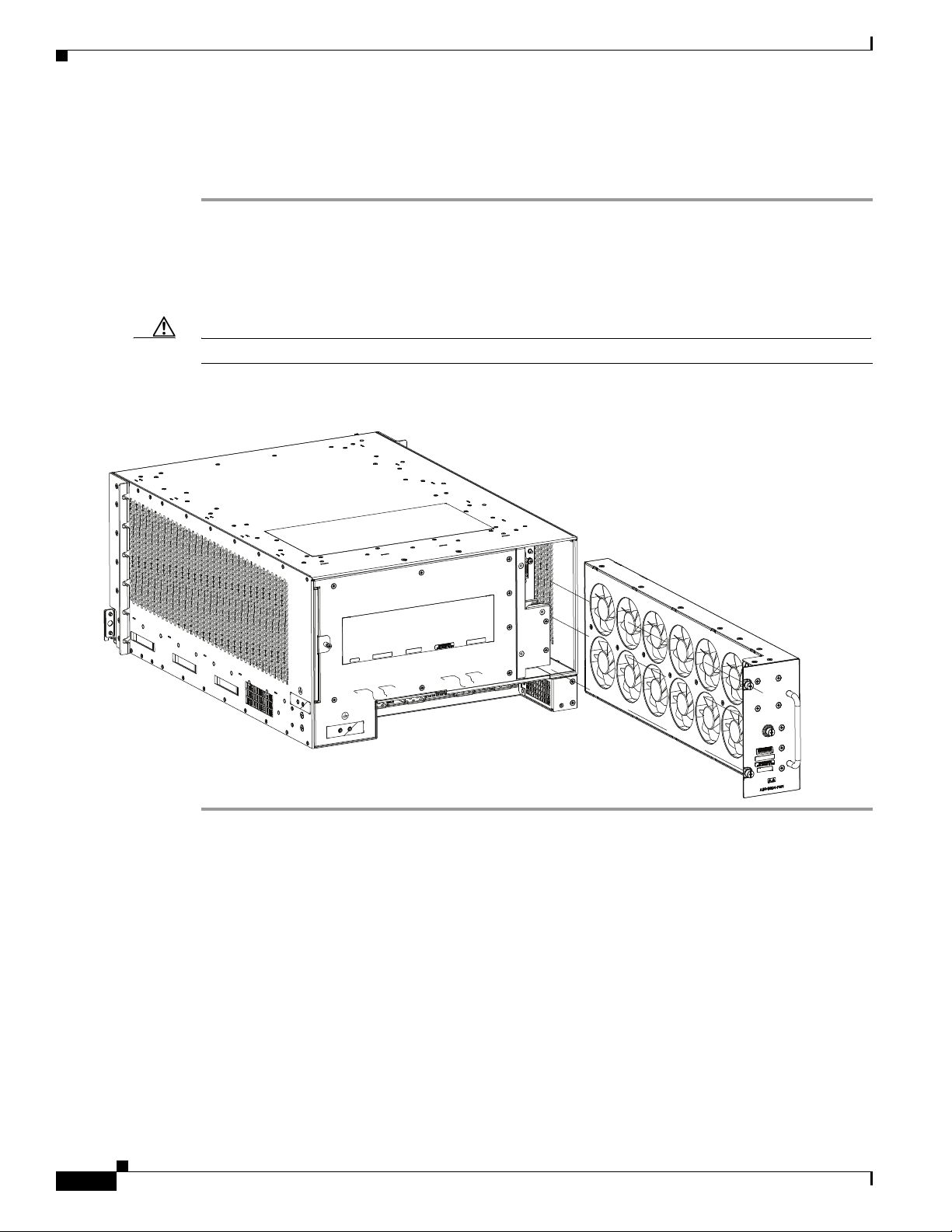
Removing Components Before Installing the Chassis
351299
Removing a Fan Tray from the Cisco ASR 9904 Router
Follow these steps to remove a fan tray from the Cisco ASR 9904 Router (Figure 2-18).
Step 1 Loosen the three captive installation screws on the front of the fan tray.
Step 2 Using the handle on the front panel, pull the fan tray halfway out of the chassis.
Step 3 Wait a few seconds for all the fans to stop rotating before lifting the fan tray from the chassis.
Step 4 Slide out the fan tray completely from the chassis while supporting it with your other hand.
Caution Use two hands when handling the fan tray. The fan tray weighs about 11.0 pounds (4.99 kg).
Figure 2-18 Removing or Installing the Fan Tray on the Cisco ASR 9904 Router Chassis
Chapter 2 Unpacking and Installing the Chassis
2-22
Cisco ASR 9000 Series Aggregation Services Router Hardware Installation Guide
Page 97
Chapter 2 Unpacking and Installing the Chassis
Removing Cards from the Chassis
To reduce additional weight from the chassis, you can remove all Route Switch Processor (RSP), Route
Processor (RP), Switch Fabric Card (FC), shared port adapter (SPA), SPA interface processor (SIP), and
line cards (LCs).
This section describes how to remove the RSP cards, RP cards, FCs, and LCs. For information about
removing SPA and SIP cards, see:
Cisco ASR 9000 Series Aggregation Services Router SIP and SPA Hardware Installation Guide
Caution Handle all cards by the metal card carrier edges only; avoid touching the board or any connector pins.
After removing a card, carefully place it in an antistatic bag or similar environment to protect it from
ESD and dust in the optic ports (fiber-optic line cards).
Caution Be careful to avoid damaging the electromagnetic interference (EMI) gasket that runs along the full
height of the card front panel edge. Damage to the EMI gasket can affect the ability of your system to
meet EMI requirements.
Removing Components Before Installing the Chassis
Caution To avoid damaging card mechanical components, never carry a card by the captive installation screws or
ejector levers. Doing so can damage these components and cause card insertion problems.
Removing RSP Cards and Line Cards from the Cisco ASR 9010 Router, Cisco ASR 9006 Router, and Cisco ASR 9904 Router
This section describes how to remove RSP and line cards from the Cisco ASR 9010 Router,
Cisco ASR 9006 Router, and Cisco ASR 9904 Router. Tabl e 2-1 and Ta ble 2-2 describe the router
components and slot numbering for each router.
Cisco ASR 9000 Series Aggregation Services Router Hardware Installation Guide
2-23
Page 98

Chapter 2 Unpacking and Installing the Chassis
Removing Components Before Installing the Chassis
Table 2-1 Router Components and Slot Numbering for the Cisco ASR 9010 Router, Cisco ASR 9006 Router, and
Cisco ASR 9904 Router
Router Model Number Router Components and Slot Numbering
Cisco ASR 9010 Router
Cisco ASR 9006 Router
Cisco ASR 9904 Router
• 10 slots.
• Version 1 power system (Figure 2-19), Version 2 power system (Figure 2-20), or Version
3 power system (Figure 2-19 for AC and Figure 2-20 for DC).
• Two RSP cards installed in the two center slots (labeled RSP0 and RSP1).
• Four line cards installed in slots 0 through 3 to the left of the RSP card slots.
• Four line cards installed in slots 4 though 7 to the right of the RSP card slots.
• 6 slots.
• Version 1 power system (Figure 2-21) or Version 2 power system (Figure 2-22).
• Two RSP cards installed in the two lowest slots (labeled RSP0 and RSP1) located above
the power modules.
• Four line cards installed in slots 2 through 5 above the RSP card slots.
• 4 slots.
• Version 2 power system (Figure 2-21).
• One line card installed in the top slot (labeled LC1). Two RSP cards installed in the
middle two slots (labeled RSP1 and RSP0) located between the line cards (LC0 and
LC1).
• One line card installed in the lowest slot (LC0) located above the power modules.
2-24
Cisco ASR 9000 Series Aggregation Services Router Hardware Installation Guide
Page 99
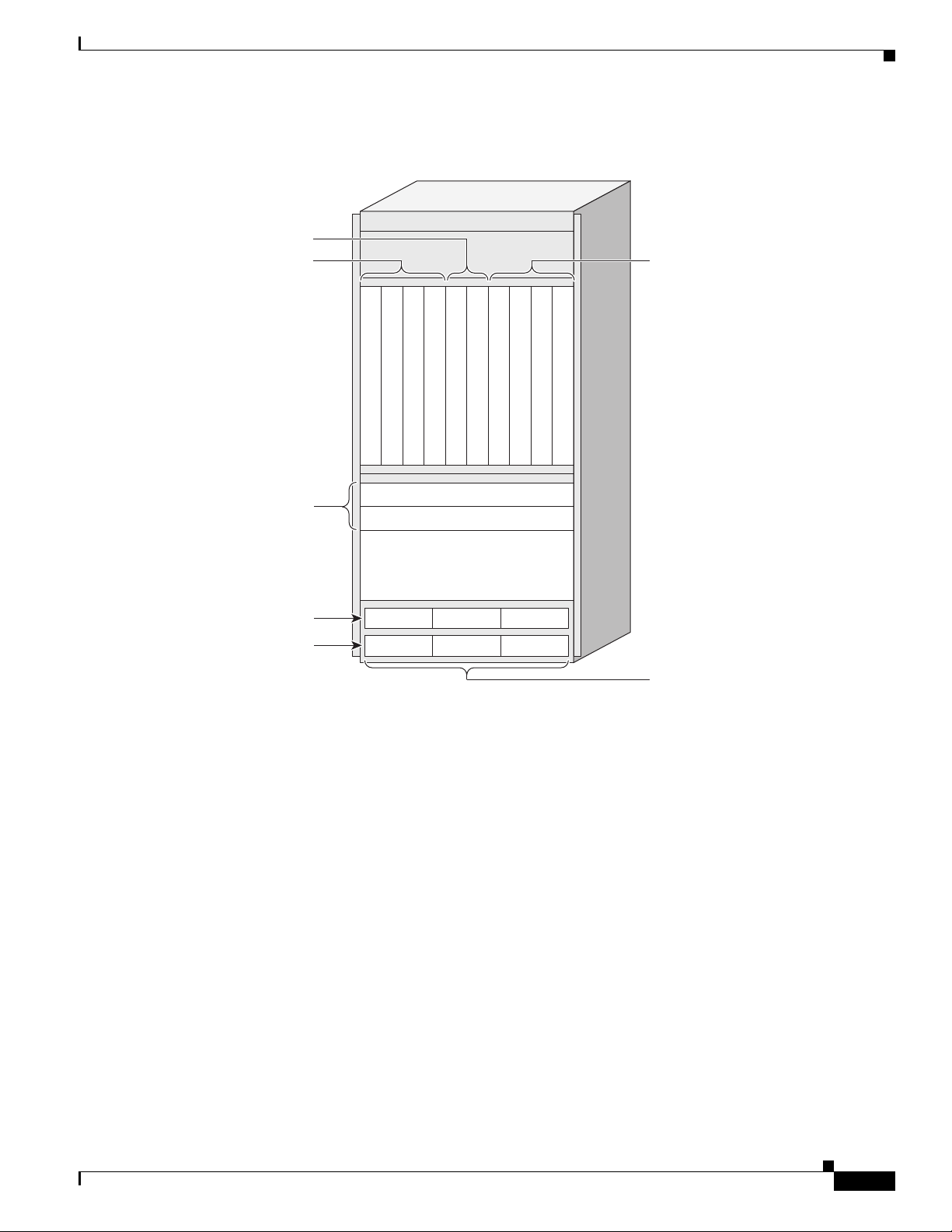
Chapter 2 Unpacking and Installing the Chassis
242689
Line card
Line card
Line card
Line card
RSP0
RSP1
FT0
FT1
Front air intake
Line card
Line card
Line card
Line card
Slot 0
Slot 1
Slot 2
Slot 3
Slot 4
Slot 5
Slot 6
Slot 7
Slot 8
Slot 9
Power shelves
PS0
PS1
Power modules
M0 M1 M2
M0 M1 M2
Line cards 0-3
Fan trays
Line cards 4-7
RSP cards
0123 4567
Figure 2-19 Cisco ASR 9010 Router Components and Slot Numbering with Version 1 Power
Removing Components Before Installing the Chassis
System or Version 3 AC Power System
Cisco ASR 9000 Series Aggregation Services Router Hardware Installation Guide
2-25
Page 100
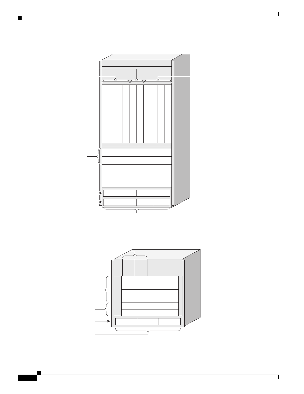
Removing Components Before Installing the Chassis
284401
Line card
Line card
Line card
Line card
RSP0
RSP1
FT0
FT1
Front air intake
Line card
Line card
Line card
Line card
Slot 0
Slot 1
Slot 2
Slot 3
Slot 4
Slot 5
Slot 6
Slot 7
Slot 8
Slot 9
PS0
PS1
Power modules
M0 M1 M2
M0 M1 M2
M3
M3
Fan trays
Line cards 4-7
RSP cards
0123 4567
243377
Line card 3
FT0
M0 M1 M2
FT1
Line card 2
Line card 1
Line card 0
RSP1
RSP0
Slot 5
Slot 4
Slot 3
Slot 2
Slot 1
Slot 0
Power shelf
Power modules
Fan trays
RSP cards
Line cards
Figure 2-20 Cisco ASR 9010 Router Components and Slot Numbering with Version 2 Power
System or Version 3 DC Power System
Chapter 2 Unpacking and Installing the Chassis
2-26
Figure 2-21 Cisco ASR 9006 Router Components and Slot Numbering with Version 1 Power
System
Cisco ASR 9000 Series Aggregation Services Router Hardware Installation Guide
 Loading...