

Page 1
Screws
(4)
Anchors
(4)
Machine
screws
(2)
Ethernet
cable
Lock-down
key
Wall bracketPhone bracket
274935
APPENDIX
E
Installing the Wall Mount for the
Cisco Unified IP Phone
This appendix contains information about installing the wall mount for use with the following:
• Installing the Wall Mount for Cisco Unified IP Phone 8961, 9951, and 9971
• Installing a Wall Mount for a Phone with a Key Expansion Module
Installing the Wall Mount for Cisco Unified IP Phone 8961, 9951, and 9971
This section describes how to install a wall mount for the Cisco Unfilled IP Phone 8961, 9951, and 9971.
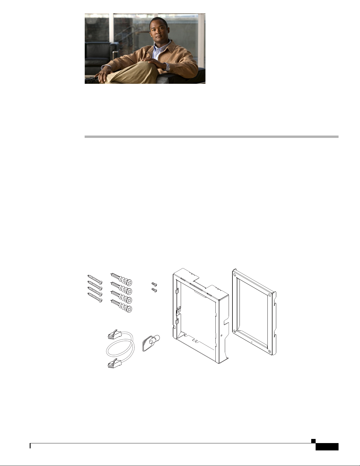
Figure E-1 Wall Mount Kit for a Single Phone Assembly
The package includes these items:
• 1 phone bracket
• 1 wall bracket
• 4 10-12x1 inch Phillips-head screws with 4 anchors
• 1 sheet metal screw
Cisco Unified IP Phone 8961, 9951, and 9971 Administration Guide for Cisco Unified Communications Manager 8.6 (SIP)
E-1
Page 2

Installing the Wall Mount for Cisco Unified IP Phone 8961, 9951, and 9971
• 2 4-40x1/4 inch machine screws
• 1 six-inch Ethernet cable
• 1 key if the bracket includes the optional lock
Before You Begin
You need these tools to install the bracket:
• #1 and #2 Phillips-head screwdrivers
• Level
You must also install an Ethernet jack for the telephone in the desired location if an Ethernet jack does
not currently exist. This jack must be wired appropriately for an Ethernet connection. You cannot use a
regular telephone jack. For more information about phone installation requirements and warnings, see
the Setting Up the Cisco Unified IP Phone chapter.
Installing the Bracket
Appendix E Installing the Wall Mount for the Cisco Unified IP Phone
To install the phone on the wall, perform the following steps:
Procedure
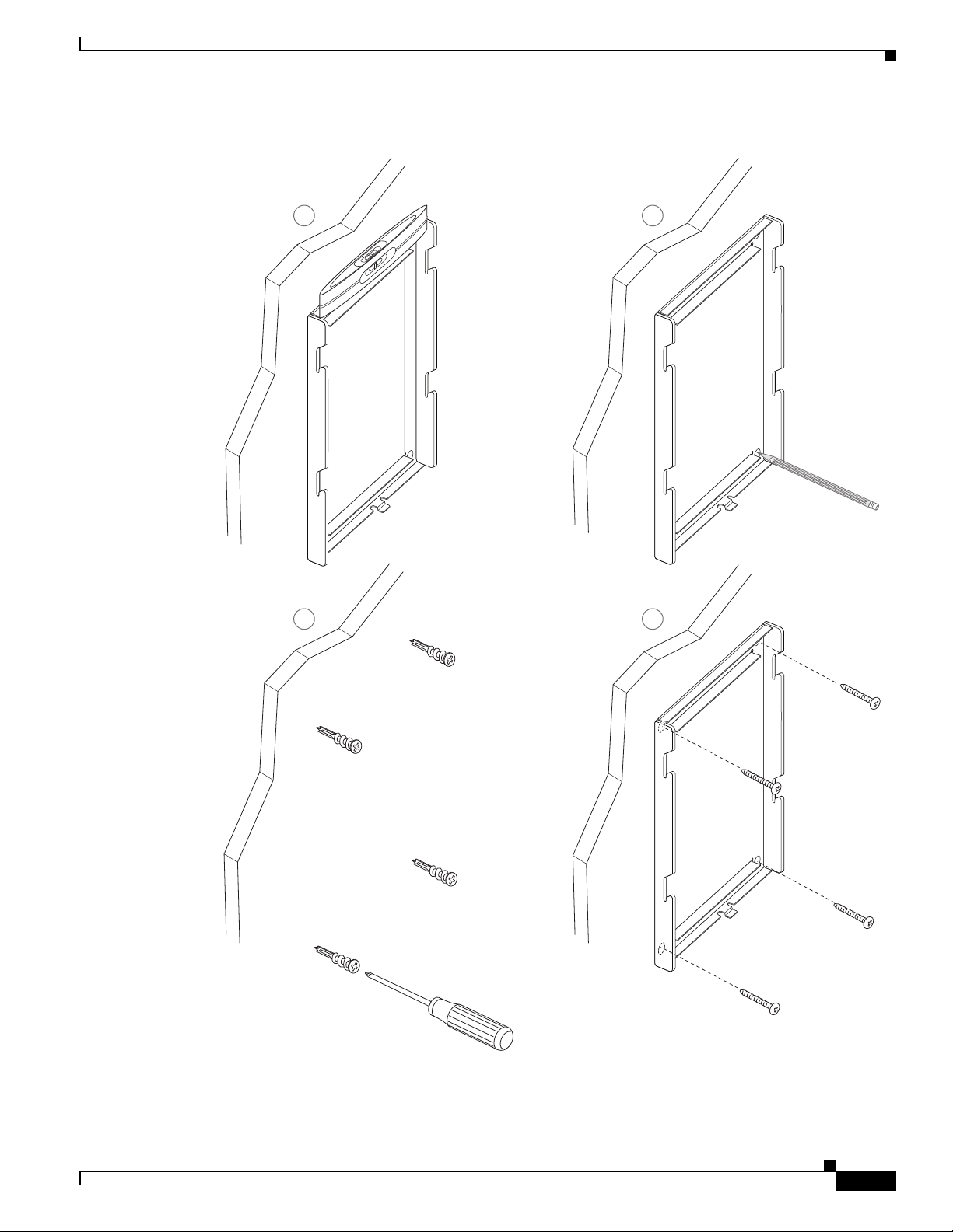
Step 1 Mount the wall bracket in the desired location (Figure E-2). You can install the bracket over an Ethernet
jack, or you can run the Ethernet network cable to a jack nearby.
a. Use the Level to ensure the bracket is level, then use a pencil to mark the screw holes.
b. Using a #2 Phillips-head screwdriver, carefully center the anchor over the pencil mark and press the
anchor into the wall.
c. Screw the anchor clockwise into the wall until it is seated flush.
d. Use the included screws and a #2 Phillips-head screwdriver to attach the bracket to the wall.
E-2
Cisco Unified IP Phone 8961, 9951, and 9971 Administration Guide for Cisco Unified Communications Manager 8.6 (SIP)
Page 3
Appendix E Installing the Wall Mount for the Cisco Unified IP Phone
Figure E-2 Mounting the Wall Bracket
Installing the Wall Mount for Cisco Unified IP Phone 8961, 9951, and 9971
A
Level wall
bracket on wall
C D
B
Mark mounting
holes through
bracket on wall
Screw bracket
to wall using
Insert anchors
into wall
Cisco Unified IP Phone 8961, 9951, and 9971 Administration Guide for Cisco Unified Communications Manager 8.6 (SIP)
Phillips head
screws
274936
E-3
Page 4
Installing the Wall Mount for Cisco Unified IP Phone 8961, 9951, and 9971
274937
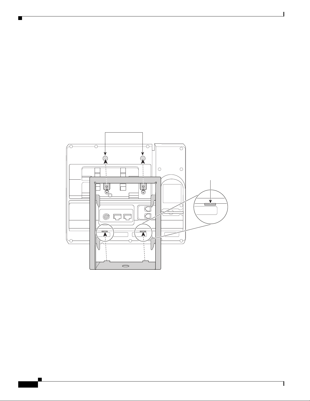
Screw holes
Slot for
mounting tabs
Step 2 Attach the phone bracket to the IP Phone (Figure E-3).
a. Detach the handset cord (and headset cord, if there is a headset), power cord, and any other attached
cords from the base of the phone.
b. Remove the label covers that are concealing the screw holes.
c. Attach the phone bracket by inserting the tabs into the mounting tabs on the phone. The ports of the
phone should be accessible through the holes in the bracket.
d. Secure the phone bracket to the IP Phone with the machine screws.
e. Thread the handset cord (and headset cord, if using one). Reattach the cords and seat them in the
clips incorporated into the phone body.
Figure E-3 Attaching the Phone Bracket
Appendix E Installing the Wall Mount for the Cisco Unified IP Phone
E-4
Cisco Unified IP Phone 8961, 9951, and 9971 Administration Guide for Cisco Unified Communications Manager 8.6 (SIP)
Page 5
Appendix E Installing the Wall Mount for the Cisco Unified IP Phone
21 3
192897
4
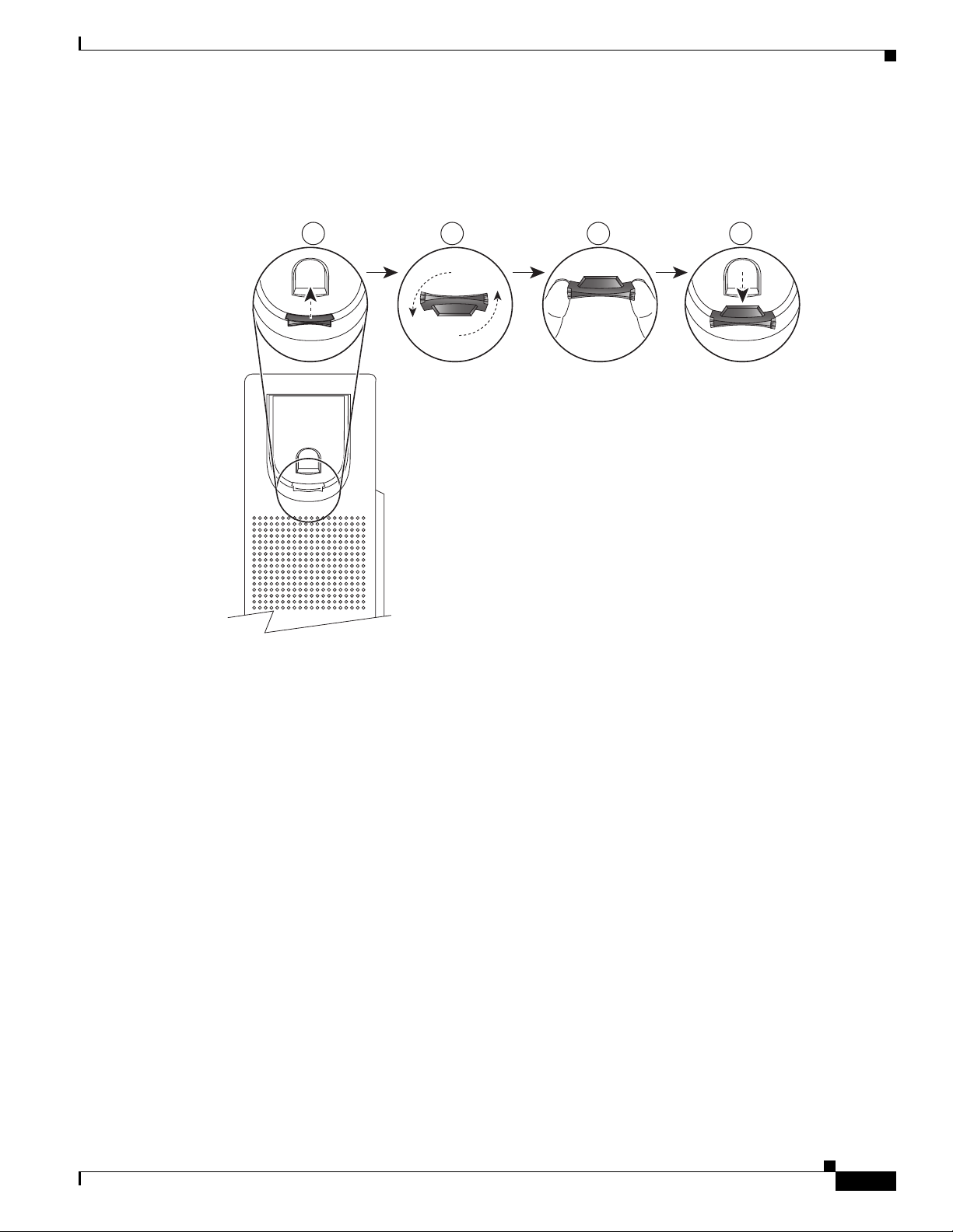
Step 3 Remove the handset wall hook in the handset rest, rotate the hook 180 degrees, and reinsert the hook.
The hook should have a lip on which the handset catches when the phone is vertical (Figure E-4).
Figure E-4 Preparing the Handset Hook
Installing the Wall Mount for Cisco Unified IP Phone 8961, 9951, and 9971
Cisco Unified IP Phone 8961, 9951, and 9971 Administration Guide for Cisco Unified Communications Manager 8.6 (SIP)
E-5
Page 6

Installing the Wall Mount for Cisco Unified IP Phone 8961, 9951, and 9971
(optional power
cable)
AC adapter
port
Phone bracket
Handset port
Wall bracket
Network
port
206801
Step 4 Attach the Ethernet cable to the 10/100/1000 SW network port and wall jack.
If you are connecting a network device (such as a computer) to the phone, attach the cable to the
10/100/1000 Computer (PC access) port.
If you are using an external power supply, plug the power cord into the phone and dress the cord by
clipping it into the clips incorporated into the phone body next to the PC port (Figure E-5).
Figure E-5 Attaching the Cables
Appendix E Installing the Wall Mount for the Cisco Unified IP Phone
E-6
Cisco Unified IP Phone 8961, 9951, and 9971 Administration Guide for Cisco Unified Communications Manager 8.6 (SIP)
Page 7

Appendix E Installing the Wall Mount for the Cisco Unified IP Phone
Step 5 Attach the phone to the wall bracket by inserting the tabs on the top of the phone bracket into the slots
on the wall bracket. Ensure that the power cord and any other cable that does not terminate in the wall
behind the bracket are positioned in one of the cable-access openings in the bottom of the bracket. The
phone and wall brackets’ openings together form circular openings with room for one cable per opening
(Figure E-6).
Step 6 Use the locking key to lock the phone to the wall bracket.
Figure E-6 Attaching the Phone to the Wall Bracket
Installing the Wall Mount for Cisco Unified IP Phone 8961, 9951, and 9971
Cisco Unified IP Phone 8961, 9951, and 9971 Administration Guide for Cisco Unified Communications Manager 8.6 (SIP)
E-7
Page 8

Appendix E Installing the Wall Mount for the Cisco Unified IP Phone
screw
Machine
screws
(3)
Ethernet
cable
Lock-down
key
206769
(4) (4)
Installing a Wall Mount for a Phone with a Key Expansion Module
Installing a Wall Mount for a Phone with a Key Expansion
Module
This section describes how to install a wall mount for the Cisco Unified IP Phone 8961, 9951, and 9971
connected with the Key Expansion Module.
Figure E-7 Wall Mount Kit for Phone with Key Expansion Module
Before You Begin
The package includes these items:
• 1 phone bracket
• 1 wall bracket
• 4 10-12x1 inch Phillips-head screws with 4 anchors
• 1 sheet metal screw
• 3 4-40x1/4 inch machine screws
• 1 six-inch Ethernet cable
• 1 key if the bracket includes the optional lock
You need these tools to install the bracket:
• #1 and #2 Phillips-head screwdrivers
• Level
You must also install an Ethernet jack for the telephone in the desired location if an Ethernet jack does
not currently exist. This jack must be wired appropriately for an Ethernet connection. You cannot use a
regular telephone jack. For more information about phone installation requirements and warnings, see
the Setting Up the Cisco Unified IP Phone chapter.
E-8
Cisco Unified IP Phone 8961, 9951, and 9971 Administration Guide for Cisco Unified Communications Manager 8.6 (SIP)
Page 9

Appendix E Installing the Wall Mount for the Cisco Unified IP Phone
Installing the Bracket
To install the phone on the wall, perform the following steps:
Note Be sure to connect to connect the Cisco Unified IP Phone to the Key Expansion Module before installing
the phone bracket.
Procedure
Step 1 Mount the wall bracket in the desired location (Figure E-8). You can install the bracket over an Ethernet
jack, or you can run the Ethernet network cable to a jack nearby.
a. Use the level to ensure the bracket is level, then use a pencil to mark the screw holes.
b. Using a #2 Phillips-head screwdriver, carefully center the anchor over the pencil mark and press the
anchor into the wall.
c. Screw the anchor clockwise into the wall until it is seated flush.
d. Use the included screws and a #2 Phillips-head screwdriver to attach the bracket to the wall.
Installing a Wall Mount for a Phone with a Key Expansion Module
Cisco Unified IP Phone 8961, 9951, and 9971 Administration Guide for Cisco Unified Communications Manager 8.6 (SIP)
E-9
Page 10

Installing a Wall Mount for a Phone with a Key Expansion Module
Figure E-8 Mounting the Wall Bracket
Appendix E Installing the Wall Mount for the Cisco Unified IP Phone
A
Level wall
bracket on wall
C D
B
Mark mounting
holes through
bracket on wall
E-10
Insert anchors
into wall
Cisco Unified IP Phone 8961, 9951, and 9971 Administration Guide for Cisco Unified Communications Manager 8.6 (SIP)
Screw bracket
to wall using
Phillips head
screws
206799
Page 11

Appendix E Installing the Wall Mount for the Cisco Unified IP Phone
206770
Slot for
mounting tabs
Screw holes
Step 2 Attach the phone bracket to the IP Phone and key expansion assembly (Figure E-9).
a. Detach the handset cord (and headset cord, if there is a headset), power cord, and any other attached
cords from the base of the phone.
b. Remove the label covers that are concealing the screw holes.
c. Attach the phone bracket by inserting the tabs into the mounting tabs on the phone. The ports of the
phone should be accessible through the holes in the bracket.
d. Secure the phone bracket to the IP Phone with the machine screws.
e. Thread the handset cord (and headset cord, if using one). Reattach the cords and seat them in the
clips incorporated into the phone body.
Figure E-9 Attaching the Phone Bracket
Installing a Wall Mount for a Phone with a Key Expansion Module
Cisco Unified IP Phone 8961, 9951, and 9971 Administration Guide for Cisco Unified Communications Manager 8.6 (SIP)
E-11
Page 12

Installing a Wall Mount for a Phone with a Key Expansion Module
Step 3 Remove the handset wall hook in the handset rest, rotate the hook 180 degrees, and reinsert the hook.
The hook should have a lip on which the handset catches when the phone is vertical (Figure E-10).
Figure E-10 Preparing the Handset Hook
Appendix E Installing the Wall Mount for the Cisco Unified IP Phone
192897
21 3
4
E-12
Cisco Unified IP Phone 8961, 9951, and 9971 Administration Guide for Cisco Unified Communications Manager 8.6 (SIP)
Page 13

Appendix E Installing the Wall Mount for the Cisco Unified IP Phone
(optional power
cable)
AC adapter
port
Phone bracket
Handset port
Wall bracket
Network
port
206771
Step 4 Attach the Ethernet cable to the 10/100/1000 SW Network port and wall jack.
If you are connecting a network device (such as a computer) to the phone, attach the cable to the
10/100/1000 Computer (PC access) port.
If you are using an external power supply, plug the power cord into the phone and dress the cord by
clipping it into the clips incorporated into the phone body next to the port (Figure E-11).
Figure E-11 Plugging the Power Cord into the Phone
Installing a Wall Mount for a Phone with a Key Expansion Module
Cisco Unified IP Phone 8961, 9951, and 9971 Administration Guide for Cisco Unified Communications Manager 8.6 (SIP)
E-13
Page 14

Installing a Wall Mount for a Phone with a Key Expansion Module
Step 5 Attach the phone to the wall bracket by inserting the tabs on the top of the phone bracket into the slots
on the wall bracket. Ensure that the power cord and any other cable that does not terminate in the wall
behind the bracket are positioned in one of the cable-access openings in the bottom of the bracket. The
phone and wall brackets’ openings together form circular openings with room for one cable per opening
(Figure E-12).
Step 6 Use the locking key to lock the phone to the wall bracket.
Figure E-12 Attaching the Phone to the Wall Bracket
Appendix E Installing the Wall Mount for the Cisco Unified IP Phone
E-14
Cisco Unified IP Phone 8961, 9951, and 9971 Administration Guide for Cisco Unified Communications Manager 8.6 (SIP)
 Loading...