

Page 1

Cisco Unified IP Phone 8961, 9951, and 9971 Administration Guide for Cisco Unified Communications Manager 8.5 (SIP)
Americas Headquarters
Cisco Systems, Inc.
170 West Tasman Drive
San Jose, CA 95134-1706
USA
http://www.cisco.com
Tel: 408 526-4000
800 553-NETS (6387)
Fax: 408 527-0883
Text Part Number: OL-20862-01
Page 2

THE SPECIFICATIONS AND INFORMATION REGA RDING THE P RODUCTS IN THIS MA NUAL ARE SUBJECT TO CHANGE W ITH OUT NOT ICE. A LL
STATEMENTS, INFORMATION, AND RECOMMENDATIONS IN THIS MANUAL ARE BELIEVED TO BE ACCURATE BUT ARE PRESENTED WITHOUT
WARRANTY OF ANY KIND, EXPRESS OR IMPLIED. USERS MUST TAKE FULL RESPONSIBILIT Y FOR THEIR APPLICATION OF ANY PRODUCTS.
THE SOFTWARE LICENSE AND LIMITED WARRA NTY FO R THE A CCOMPA NYING PRODUCT A RE SET FORTH IN T HE INFORM ATION P ACKET THAT
SHIPPED WITH THE PRODUCT AND ARE INCORPORATED HEREIN BY THIS REFERENCE. IF YOU ARE UNABLE TO LOCATE THE SOFTWARE LICENSE
OR LIMITED WARRANTY, CONTACT YOUR CISCO REPRESENTATIVE FOR A COPY.
The following information is for FCC compliance of Class A devices: This equipment has been tested and found to comply with the limits for a Class A di gital device, pursuant
to part 15 of the FCC rules. These limits are designed to provide reasonable protection against harmful interference when the equipment is operated in a commercial
environment. This equipment generates, uses, and can radiate radio-frequency energy and, if not installed and used in accordance with the instruction manual, may cause
harmful interference to radio communications. Operation of this equipment in a residential area is likely to cause harmful interference, in which case users will be required
to correct the interference at their own expense.
The following information is for FCC compliance of Class B devices: The equipment described in this manual generates and may radiate radio-frequency energy. If it is not
installed in accordance with Cisco’s installation instructions, it may cause interference with radio and television reception. This equipment has been tested and found to
comply with the limits for a Class B digital device in accordance with the specifications in part 15 of the FCC rules. These specifications are designed to provide reasonable
protection against such interference in a residential installation. However, there is no guarantee that interference will not occur in a particular installation.
Modifying the equipment without Cisco’s written authorization may result in the equipment no longer complying with FCC requirements for Class A or Class B digital
devices. In that event, your right to use the equipment may be limited by FCC regulations, and you may be required to correct any interference to radio or television
communications at your own expense.
You can determine whether your equipment is causing interference by turning it off. If the interference stops, it was probabl y caused by the Cisco equipment or one of its
peripheral devices. If the equipment causes interference to radio or television reception, try to correct the interference by using one or more of the following measures:
• Turn the television or radio antenna until the interference stops.
• Move the equipment to one side or the other of the television or radio.
• Move the equipment farther away from the television or radio.
• Plug the equipment into an outlet that is on a different circuit from the television or radio. (That is, make certain the equipment and the television or radio are on circuits
controlled by different circuit breakers or fuses.)
Modifications to this product not authorized by Ci sco Systems, Inc. cou ld void th e FCC approval and negate your auth ority to op erate the product.
The Cisco implementation of TCP header compression is an adaptation of a program developed by the University of California, Berkeley (UCB) as part of UCB’s public
domain version of the UNIX operating system. All rights reserved. Copyright © 1981, Regents of the University of California.
NOTWITHSTANDING ANY OTHER WARRANTY HEREIN, ALL DO CUMENT FILES AND SOFTWARE OF THESE SUPPL IERS ARE PROVI DED “AS IS” WITH
ALL FAULTS. CISCO AND THE ABOVE-NAMED SUPPLIERS DISCLAI M ALL WARRANTIE S, EXPRESSED OR IMPLIE D, INCLUDING, WITHOUT
LIMITATION, THOSE OF MERCHANTABILITY, FITNESS FOR A PARTICUL AR PURPOSE AN D NONINFRINGEM ENT OR ARISING FROM A COURSE OF
DEALING, USAGE, OR TRADE PRACTICE.
IN NO EVENT SHALL CISCO OR ITS SUPPLIERS BE LIABLE FOR ANY INDIRECT, SPECIAL, CONSEQUENTIAL, OR INCIDENTAL DAMAGES, INCLUDING,
WITHOUT LIMITATION, LOS T PROFITS OR LOSS OR DAMAGE TO DATA ARISIN G OUT OF THE USE OR INABILI TY TO USE THIS MA NUAL, EVEN I F CISCO
OR ITS SUPPLIERS HAVE BEEN ADVISED OF THE POSSIBILITY OF SU CH DAMA GES.
Cisco and the Cisco logo are trademarks or registered trademarks of Cisco and/or its affiliates in the U.S. and other countries. To view a list of Cisco trademarks, go to this
URL: www.cisco.com/go/trademarks. Third-p arty tr ademarks mentio ned are the p roperty o f their respective owners. The use of the wo rd partner does not imply a partnership
relationship between Cisco and any other company. (1110R)
The Java logo is a trademark or registered trademark of Sun Microsystems, Inc. in the U.S. or other countries.
Cisco Unified IP Phone 8961, 9951, and 9971 Administration Guide for Cisco Unified Communications Manager 8.5 (SIP)
© 2013 Cisco Systems, Inc. All rights reserved.
Page 3

CONTENTS
Preface xi
Overview xi
Audience xi
Organization xi
Related Documentation xiii
Obtaining Documentation, Obtaining Support, and Security Guidelines xiii
Document Conventions xiv
CHAPTER
1 An Overview of the Cisco Unified IP Phone 1-1
Understanding the Cisco Unified IP Phone 8961, 9951, and 9971 1-2
What Networking Protocols are Used? 1-10
What Features are Supported on the Cisco Unified IP Phone 8961, 9951, and 9971? 1-13
Feature Overview 1-13
Configuring Telephony Features 1-14
Configuring Network Parameters Using the Cisco Unified IP Phone 1-14
Providing Users with Feature Information 1-15
Understanding Security Features for Cisco Unified IP Phones 1-15
Overview of Supported Security Features 1-16
Understanding Security Profiles 1-19
Identifying Secure (Encrypted) Phone Calls 1-19
Establishing and Identifying Secure Conference Calls 1-19
Establishing and Identifying Secure Calls 1-20
Call Security Interactions and Restrictions 1-20
Supporting 802.1X Authentication on Cisco Unified IP Phones 1-22
Overview 1-22
Required Network Components 1-22
Best Practices—Requirements and Recommendations 1-22
Security Restrictions 1-23
OL-20861-01
Overview of Configuring and Installing Cisco Unified IP Phones 1-23
Configuring Cisco Unified IP Phones in Cisco Unified Communications Manager 1-24
Checklist for Configuring the Cisco Unified IP Phone 8961, 9951, and 9971 in Cisco Unified
Communications Manager
1-25
Installing Cisco Unified IP Phones 1-28
Checklist for Installing the Cisco Unified IP Phone 8961, 9951, and 9971 1-28
Cisco Unified IP Phone 8961, 9951, and 9971 Administration Guide for Cisco Unified Communications Manager 8.5 (SIP)
iii
Page 4

Contents
Terminology Information 1-30
CHAPTER
2 Preparing to Install the Cisco Unified IP Phone on Your Network 2-1
Understanding Interactions with Other Cisco Unified IP Telephony Products 2-1
Understanding How the Cisco Unified IP Phone Interacts with Cisco Unified Communications
Manager
2-2
Understanding How the Cisco Unified IP Phone Interacts with the VLAN 2-2
Providing Power to the Cisco Unified IP Phone 2-3
Power Guidelines 2-4
Power Outage 2-4
Reducing Power Consumption on the Phone 2-4
Power Negotiation over LLDP 2-5
Obtaining Additional Information About Power 2-5
Understanding Phone Configuration Files 2-6
Understanding the Phone Startup Process 2-7
Adding Phones to the Cisco Unified Communications Manager Database 2-9
Adding Phones with Auto-Registration 2-10
Adding Phones with Auto-Registration and TAPS 2-11
Adding Phones with Cisco Unified Communications Manager Administration 2-12
Adding Phones Using BAT Phone Template 2-12
CHAPTER
Determining the MAC Address for a Cisco Unified IP Phone 2-13
3 Setting Up the Cisco Unified IP Phone 3-1
Before You Begin 3-1
Network Requirements 3-1
Cisco Unified Communications Manager Configuration 3-2
Understanding the Cisco Unified IP Phone Components 3-2
Network and Computer Ports 3-3
Handset Rest 3-3
Speakerphone 3-4
Accessory Support on the Cisco Unified IP Phone 8961, 9951, and 9971 3-4
USB Port Data Information 3-5
External Speakers and Microphone 3-5
Headsets 3-5
Audio Quality Subjective to the User 3-6
Wired Headsets 3-6
USB Headsets 3-6
Analog Headsets 3-7
Wireless Headsets 3-8
iv
Cisco Unified IP Phone 8961, 9951, and 9971 Administration Guide for Cisco Unified Communications Manager 8.5 (SIP)
OL-20861-01
Page 5

Using Bluetooth Wireless Headsets 3-8
Handsfree Profile 3-8
Important Note about Headset Types 3-10
Using External Devices 3-11
Installing the Cisco Unified IP Phone 3-11
Connecting the Footstand 3-19
Phone Display Viewing Angle 3-20
Securing the Phone with a Cable Lock 3-20
Mounting the Phone to the Wall 3-20
Verifying the Phone Startup Process 3-21
Configuring Startup Network Settings 3-21
Configuring Security on the Cisco Unified IP Phone 3-21
Contents
CHAPTER
CHAPTER
4 Setting Up the Cisco Unified IP Color Key Expansion Module 4-1
Installing a Key Expansion Module on the Cisco Unified IP Phone 4-2
Power Information 4-2
Connecting a Single KEM to the Cisco Unified IP Phone 4-2
Connecting Two or More KEMs to the Phone Using the KEM Spine Connector 4-3
Configuring the Key Expansion Module in Cisco Unified Communications Manager Administration 4-4
Key Expansion Module Settings on the Phone 4-5
Upgrading the Key Expansion Module 4-5
Removing a Key Expansion Module 4-6
Troubleshooting 4-6
5 Setting Up the Cisco Unified Video Camera 5-1
Configuring the Cisco Unified Video Camera 5-1
Attaching the Cisco Unified Video Camera 5-2
Adjusting the Camera Settings 5-2
Adjusting the Camera View Area 5-2
Adjusting the Brightness Setting 5-3
Adjusting Auto Transmit Setting 5-3
CHAPTER
OL-20861-01
Post-Installation Steps 5-4
Using the Cisco Unified Video Camera 5-4
6 Understanding the VoIP Wireless Network 6-1
Understanding the Wireless LAN 6-1
Understanding WLAN Standards and Technologies 6-2
Cisco Unified IP Phone 8961, 9951, and 9971 Administration Guide for Cisco Unified Communications Manager 8.5 (SIP)
v
Page 6

Contents
802.11 Standards for WLAN Communications 6-3
World Mode (802.11d) 6-4
Radio Frequency Ranges 6-5
802.11 Data Rates, Tx Power, Ranges, and Decibel Tolerances 6-5
Wireless Modulation Technologies 6-6
AP, Channel, and Domain Relationships 6-7
WLANs and Roaming 6-7
Bluetooth Wireless Technology 6-7
Components of the VoIP Wireless Network 6-8
Interacting with Cisco Unified Wireless APs 6-8
Associating to APs 6-8
Voice QoS in a Wireless Network 6-9
Interacting with Cisco Unified Communications Manager 6-11
Security for Voice Communications in WLANs 6-11
Authentication Methods 6-11
Authenticated Key Management 6-12
Encryption Methods 6-13
Choosing AP Authentication and Encryption Methods 6-13
CHAPTER
VoIP WLAN Configuration 6-15
Supported Access Points 6-15
Supported APs and Modes 6-15
Supported Antennas 6-16
Configuring Wireless LAN 6-16
Summary of Configuring the Wireless LAN in Cisco Unified Communications Manager
Administration
6-17
Summary of Configuring the Wireless LAN on the Cisco Unified IP Phone 6-17
7 Configuring Settings on the Cisco Unified IP Phone 7-1
Setup Menus on the Cisco Unified IP Phone 7-1
Displaying a Setup Menu 7-2
Unlocking and Locking Options 7-3
Editing Values 7-3
Ethernet Setup Menu 7-4
WLAN Setup Menu 7-7
IPv4 Setup Menu Options 7-10
Security Setup Menu 7-13
Trust List Menu 7-14
802.1X Authentication and Transaction Status 7-15
VPN Configuration Menu 7-16
vi
Cisco Unified IP Phone 8961, 9951, and 9971 Administration Guide for Cisco Unified Communications Manager 8.5 (SIP)
OL-20861-01
Page 7

Connecting to VPN 7-16
VPN Configuration Settings 7-17
Contents
CHAPTER
8 Configuring Features, Templates, Services, and Users 8-1
Telephony Features Available for the Cisco Unified IP Phone 8-2
Park Monitoring 8-23
Setting the Service Parameters for Park Monitoring 8-24
Setting Park Monitoring Parameters in Directory Number Configuration Window 8-25
Setting Park Monitoring Parameter in Hunt Pilot Configuration Window 8-25
Configuring Product Specific Configuration Parameters 8-26
Configuring Corporate and Personal Directories 8-27
Configuring Corporate Directories 8-27
Configuring Personal Directory 8-27
Feature Buttons and Softkeys 8-28
Modifying Phone Button Templates 8-29
Modifying a Phone Button Template for All Calls 8-29
Modifying a Phone Button Template for Personal Address Book or Speed Dials 8-30
Configuring Feature Control Policies 8-31
Setting Up Services 8-32
Adding Users to Cisco Unified Communications Manager 8-33
CHAPTER
Managing the User Options Web Pages 8-34
Giving Users Access to the User Options Web Pages 8-34
Specifying Options that Appear on the User Options Web Pages 8-36
9 Customizing the Cisco Unified IP Phone 9-1
Customizing and Modifying Configuration Files 9-1
Creating Custom Phone Rings 9-2
Ringlist.xml File Format Requirements 9-2
PCM File Requirements for Custom Ring Types 9-3
Configuring a Custom Phone Ring 9-3
Creating Custom Background Images 9-4
List.xml File Format Requirements 9-4
PNG File Requirements for Custom Background Images 9-5
Configuring a Custom Background Image 9-5
Configuring Wideband Codec 9-6
Configuring the Idle Display 9-7
Automatically Disabling the Cisco Unified IP Phone Display 9-7
OL-20861-01
Cisco Unified IP Phone 8961, 9951, and 9971 Administration Guide for Cisco Unified Communications Manager 8.5 (SIP)
vii
Page 8

Contents
CHAPTER
CHAPTER
10 Viewing Model Information, Status, and Statistics on the Cisco Unified IP Phone 10-1
Model Information Screen 10-1
Status Menu 10-2
Status Messages Screen 10-3
Ethernet Statistics Screen 10-7
WLAN Statistics Screen 10-9
Call Statistics Screen 10-11
Video Statistics Screen 10-13
Current Access Point Screen 10-15
11 Monitoring the Cisco Unified IP Phone Remotely 11-1
Accessing the Web Page for a Phone 11-2
Enabling and Disabling Web Page Access 11-3
Configuring the Cisco Unified IP Phone to use HTTP/HTTPS Protocols 11-3
Device Information 11-4
Network Setup 11-5
Network Statistics 11-8
Device Logs 11-11
CHAPTER
Streaming Statistics 11-11
12 Troubleshooting and Maintenance 12-1
Resolving Startup Problems 12-1
Symptom: The Cisco Unified IP Phone Does Not Go Through its Normal Startup Process 12-2
Symptom: The Cisco Unified IP Phone Does Not Register with Cisco Unified Communications
Manager
12-2
Identifying Error Messages 12-3
Checking Network Connectivity 12-3
Verifying TFTP Server Settings 12-3
Verifying IP Addressing and Routing 12-3
Verifying DNS Settings 12-4
Cisco CallManager and TFTP Services Are Not Running 12-4
Creating a New Configuration File 12-5
Registering the Phone with Cisco Unified Communications Manager 12-5
Symptom: Cisco Unified IP Phone Unable to Obtain IP Address 12-6
Cisco Unified IP Phone Resets Unexpectedly 12-6
Verifying the Physical Connection 12-6
Identifying Intermittent Network Outages 12-6
Verifying DHCP Settings 12-7
viii
Cisco Unified IP Phone 8961, 9951, and 9971 Administration Guide for Cisco Unified Communications Manager 8.5 (SIP)
OL-20861-01
Page 9

Checking Static IP Address Settings 12-7
Verifying the Voice VLAN Configuration 12-7
Verifying that the Phones Have Not Been Intentionally Reset 12-7
Eliminating DNS or Other Connectivity Errors 12-8
Checking Power Connection 12-8
Troubleshooting Cisco Unified IP Phone Security 12-9
General Troubleshooting Tips 12-10
Resetting the Cisco Unified IP Phone 12-15
Using the Quality Report Tool 12-16
Monitoring the Voice Quality of Calls 12-16
Troubleshooting Tips 12-17
Where to Go for More Troubleshooting Information 12-17
Cleaning the Cisco Unified IP Phone 12-17
Contents
APPENDIX
APPENDIX
APPENDIX
A Providing Information to Users Via a Website A-1
How Users Obtain Support for the Cisco Unified IP Phone A-1
Giving Users Access to the User Options Web Pages A-1
How Users Subscribe to Services and Configure Phone Features A-2
How Users Access a Voice Messaging System A-2
How Users Configure Personal Directory Entries A-3
Installing and Configuring the Cisco Unified IP Phone Address Book Synchronizer A-3
B Supporting International Users B-1
Installing the Cisco Unified Communications Manager Locale Installer B-1
Support for International Call Logging B-1
C Technical Specifications C-1
Physical and Operating Environment Specifications C-1
Cable Specifications C-2
Network and Computer Port Pinouts C-2
APPENDIX
OL-20861-01
D Basic Phone Administration Steps D-1
Example User Information for these Procedures D-1
Adding a User to Cisco Unified Communications Manager D-2
Adding a User From an External LDAP Directory D-2
Adding a User Directly to Cisco Unified Communications Manager D-2
Configuring the Phone D-3
Cisco Unified IP Phone 8961, 9951, and 9971 Administration Guide for Cisco Unified Communications Manager 8.5 (SIP)
ix
Page 10

Contents
Performing Final End User Configuration Steps D-6
APPENDIX
APPENDIX
E Installing the Wall Mount for the Cisco Unified IP Phone E-1
Installing the Wall Mount for Cisco Unified IP Phone 8961, 9951, and 9971 E-1
Before You Begin E-2
Installing the Bracket E-2
Installing a Wall Mount for a Phone with a Key Expansion Module E-8
Before You Begin E-8
Installing the Bracket E-9
F Cisco Unified IP Phone Non-Lockable Wall Mount F-1
ADA Non-Lockable Wall Mount Kit for 8961 Series and 9900 Series IP Phones F-1
Components F-3
Before you begin F-4
Install Non-Lockable Wall Mount for phone F-4
Remove Phone from Non-Lockable Wall Mount F-8
ADA Non-Lockable Wall Mount Kit for 8961 Series and 9900 Series IP Phones with Key Expansion
Module
F-10
Components F-12
Before You Begin F-13
Install Non-Lockable Wall Mount Kit for Phone with Key Expansion Module F-13
Remove Phone and Key Expansion Module from Non-Lockable Wall Mount F-17
I
NDEX
Cisco Unified IP Phone 8961, 9951, and 9971 Administration Guide for Cisco Unified Communications Manager 8.5 (SIP)
x
OL-20861-01
Page 11

Overview
Preface
Cisco Unified IP Phone 8961, 9951, and 9971 Admini stration Guide for Cisco Unified Commu nications
Manager 8.5 (SIP) provides the information you need to understand, install, configure, manage, and
troubleshoot the phones on a Voice-over-IP (VoIP) network.
Because of the complexity of an IP telephony network, this g uide does not provide complete and detailed
information for procedures that you need to perform in Cisco Unified Communications Man ager or other
network devices. See the “Related Documentation” section on page xiii.
Audience
Network engineers, system administrators, or telecom engineers should review this guide to learn the
steps required to properly set up the Cisco Unified IP Phone on the network.
The tasks described are administration-level tasks and are not intended for end-users of the phones.
Many of the tasks involve configuring network settings and affect the phone’s ability to function in the
network.
Because of the close interaction between the Cisco Unified IP Phone and Ci sco Unified Communications
Manager, many of the tasks in this manual require familiarity with Cisco Unified Communications
Manager.
Organization
This manual is organized as follows:
Chapter Description
Chapter 1, “An Overview of the Cisco
Unified IP Phone”
Chapter 2, “Preparing to Install the Cisco Unified IP
Phone on Your Network”
Provides a conceptual overview and description of the Cisco Uni fied
IP Phone.
Describes how the Cisco Unified IP Phone int eracts with o ther key
IP telephony components, and provides an overview of the tasks
required prior to installation.
OL-20861-01
Cisco Unified IP Phone 8961, 9951, and 9971 Administration Guide for Cisco Unified Communications Manager 8.5 (SIP)
xi
Page 12

Preface
Chapter 3, “Setting Up the Cisco Unified IP Phone” Describes how to properly and safely install th e Cisco Unif ied IP
Phone on your network. Also provides procedures on how to
configure and add accessories, such as Bluetooth wireless headsets,
USB headsets, and analog wideband headsets, to the Cisco Unified
IP Phone.
Chapter 4, “Setting Up the Cisco Unified IP Color
Key Expansion Module”
Chapter 5, “Setting Up the Cisco Unified Video
Camera”
Chapter 6, “Understanding the VoIP Wireless
Network”
Chapter 7, “Configuring Settings on the Cisco
Unified IP Phone”
Chapter 8, “Configuring Features, Templates,
Services, and Users”
Chapter 9, “Customizing the Cisco Unified IP
Phone”
Chapter 10, “Viewing Model Information, S tatus, and
Statistics on the Cisco Unified IP Phone”
Chapter 11, “Monitoring the Cisco Unified IP Phone
Remotely”
Chapter 12, “Troubleshooting and Maintenance” Provides tips for troubleshooting the Cisco Unified IP Phone and the
Appendix A, “Providing Information to Users Via a
Website”
Appendix B, “Supporting International Users” Provides information about setting up phones in non-English
Appendix C, “Technical Specifications” Provides technical specifications of the Cisco Unified IP Phone.
Appendix D, “Basic Phone Administration Steps” Provides procedures for basic administration tasks such as adding a
Appendix E, “Installing the Wall Mount for the
Cisco Unified IP Phone”
Appendix F, “Cisco Unified IP Phone Non-Lockable
Wall Mount”
Describes how to connect and configure supported Key Expansion
Modules for the Cisco Unified IP Phone.
Describes how to configure the Cisco Unified Video Camera and add
it to the Cisco Unified IP Phone (Cisco Unified IP Phone 9951 and
9971 only).
Provides an overview and describes the setup of the wireless local
area network (WLAN), which the Cisco Unified IP Phone 9971
supports.
Describes how to configure network settings, verify status, and make
global changes to the Cisco Unified IP Phone.
Provides an overview of procedures for configuring telephony
features, configuring directories, configuring phone button and
softkey templates, setting up services, and adding users to Cisco
Unified Communications Manager.
Explains how to customize phone ring sounds and the phone idle
display at your site.
Explains how to view model information, status messages, network
statistics, and firmware information from the Cisco Unified IP
Phone.
Describes the information that you can obtain from the phone’s web
page to remotely monitor the operation of a phone and to assist with
troubleshooting.
Cisco Unified IP Phone Expansion Modules.
Provides suggestions for setting up a website for providing users
with important information about their Cisco Unified IP Phones.
environments.
user and phone to Cisco Unified Communications Manager and then
associating the user to the phone.
Contains instructions for installing the wall mount for the Cisco
Unified IP Phone.
Contains instructions for installing the Cisco Unified IP Phone
Non-Lockable Wall Mount.
xii
Cisco Unified IP Phone 8961, 9951, and 9971 Administration Guide for Cisco Unified Communications Manager 8.5 (SIP)
OL-20861-01
Page 13

Preface
Related Documentation
For more information about Cisco Unified IP Phones or Cisco Unified Communications Manager, refer
to the following publications:
Cisco Unified IP Phones 8961, 9951, and 9971
These publications are available at the following URL:
http://www.cisco.com/en/US/products/ps10453/tsd_products_support_series_home.html
• Cisco Unified IP Phone 8961, 9951, and 9971 User Guide for Cisco Unified Communications
Manager
• Regulatory Compliance and Safety Information for Cisco Unified IP Phones
• Cisco Unified IP Phones 8900 Series
Cisco Unified Communications Manager Administration
Related publications are available at the following URL:
http://www.cisco.com/en/US/products/sw/voicesw/ps556/tsd_products_support_series_home.html
Cisco Unified Communications Manager Business Edition
Related publications are available at the following URL:
http://www.cisco.com/en/US/products/ps7273/tsd_products_support_series_home.html
Obtaining Documentation, Obtaining Support, and Security
Guidelines
For information on obtaining documentation, obtaining support, providing documentation feedback,
security guidelines, and also recommended aliases and general Cisco do cuments, see the monthly What’s
New in Cisco Product Documentation, which also lists all new and revised Cisco technical
documentation, at:
http://www.cisco.com/en/US/docs/general/whatsnew/whatsnew.html
Subscribe to the What’s New in Cisco Product Documentation as a Really Simple Syndication (RSS)
feed and set content to be delivered directly to your desktop using a reader application. The RSS feeds
are a free service and Cisco currently supports RSS Version 2.0.
Cisco Product Security Overview
This product contains cryptographic features and is subject to United States and local country laws
governing import, export, transfer and use. Delivery of Cisco cryptographic products does not imply
third-party authority to import, export, distribute or use encryption. Importers, exporters, distributors
and users are responsible for compliance with U.S. and local country laws. By using this product you
agree to comply with applicable laws and regulations. If you are unable to comply with U.S. and local
laws, return this product immediately.
OL-20861-01
Further information regarding U.S. export regulations may be found at
http://www.access.gpo.gov/bis/ear/ear_data.html.
Cisco Unified IP Phone 8961, 9951, and 9971 Administration Guide for Cisco Unified Communications Manager 8.5 (SIP)
xiii
Page 14

Document Conventions
This document uses the following conventions:
Convention Description
boldface font Commands and keywords are in boldface.
italic font Arguments for which you supply values are in italics.
[ ] Elements in square brackets are optional.
{ x | y | z } Alternative keywords are grouped in braces and separated by vertical bars.
[ x | y | z ] Optional alternative keywords are grouped in brackets and separated by vertical bars.
string A nonquoted set of characters. Do not use quotation marks around t he string or the string will
include the quotation marks.
screen font Terminal sessions and information the system displays are in screen font.
boldface screen font Information you must enter is in boldface screen font.
italic screen font Arguments for which you supply values are in italic screen font.
^ The symbol ^ represents the key labeled Control—for example, the key combination ^D in a
screen display means hold down the Control key while you press the D key.
< > Nonprinting characters, such as passwords are in angle brackets.
Preface
Note Means reader take note. Notes contain helpful suggestions or references to material not covered in the
publication.
Caution Means read er be caref ul. In this situation, you might do something that could result in equipment
damage or loss of data.
Warnings use the following convention:
Warning
IMPORTANT SAFETY INSTRUCTIONS
This warning symbol means danger. You are in a situation that could cause bodily injury. Before you
work on any equipment, be aware of the hazards involved with electrical circuitry and be familiar
with standard practices for preventing accidents. Use the statement number provided at the end of
each warning to locate its translation in the translated safety warnings that accompanied this
device.
SAVE THESE INSTRUCTIONS
Statement 1071
xiv
Cisco Unified IP Phone 8961, 9951, and 9971 Administration Guide for Cisco Unified Communications Manager 8.5 (SIP)
OL-20861-01
Page 15

CHAP T E R
1
An Overview of the Cisco Unified IP Phone
The Cisco Unified IP Phone 8961, 9951, and 9971 provide voice communication over an Internet
Protocol (IP) network. The Cisco Unified IP Phone functions much like a digital business phone,
allowing you to place and receive phone calls and to access features such as mute, hold, transfer, speed
dial, call forward, and more. In addition, because the phone is connected to your data network, it offers
enhanced IP telephony features, including access to network information and services, and
customizeable features and services.
The Cisco Unified IP Phone 8961, 9951, and 9971 have the following features:
• 24-bit color phone screen (Cisco Unified IP Phone 9971 has touchscreen support)
• Programmable feature buttons that support up to 5 lines (6 lines for the Cisco Unified
IP
Phone 9971) or can be programmed for other features
• Full video capabilities (Cisco Unified IP Phone 9951 and 9971 only)
• Gigabit ethernet connectivity
• Support for an external microphone and speakers
• Bluetooth support for wireless headsets (Cisco Unified IP Phone 9951 and 9971 only)
• Network connectivity by Wi-Fi (Cisco Unified IP Phone 9971 only)
OL-20861-01
• 2 USB ports for Cisco Unified IP Phones 9951 and 9971 and one USB port for Cisco Unified IP
Phone 8961
A Cisco Unified IP Phone, like other network devices, must be configured and managed. These phones
encode G.711a-law, G.711µ-law, G.722, G.729a, G.729ab, and iLBC, and decode G.711a-law,
G.711µ-law, G.722, G.729, G.729a, G.729b, G.729ab, and iLBC.
This chapter includes the following topics:
• Understanding the Cisco Unified IP Phone 8961, 9951, and 9971, page 1-2
• What Networking Protocols are Used?, page 1-10
• What Features are Supported on the Cisco Unified IP Phone 8961, 9951, and 9971?, page 1-13
• Understanding Security Features for Cisco Unified IP Phones, page 1-15
• Overview of Configuring and Installing Cisco Unified IP Phones, page 1-23
• Terminology Information, page 1-30
Caution Using a cell, mobile, or GSM phone, or two-way radio in close proximity to a Cisco Unified IP Phone
might cause interference. For more information, refer to the manufacturer’s documentation of the
interfering device.
Cisco Unified IP Phone 8961, 9951, and 9971 Administration Guide for Cisco Unified Communications Manager 8.5 (SIP)
1-1
Page 16
Chapter 1 An Overview of the Cisco Unified IP Phone
Understanding the Cisco Unified IP Phone 8961, 9951, and 9971
Understanding the Cisco Unified IP Phone 8961, 9951, and 9971
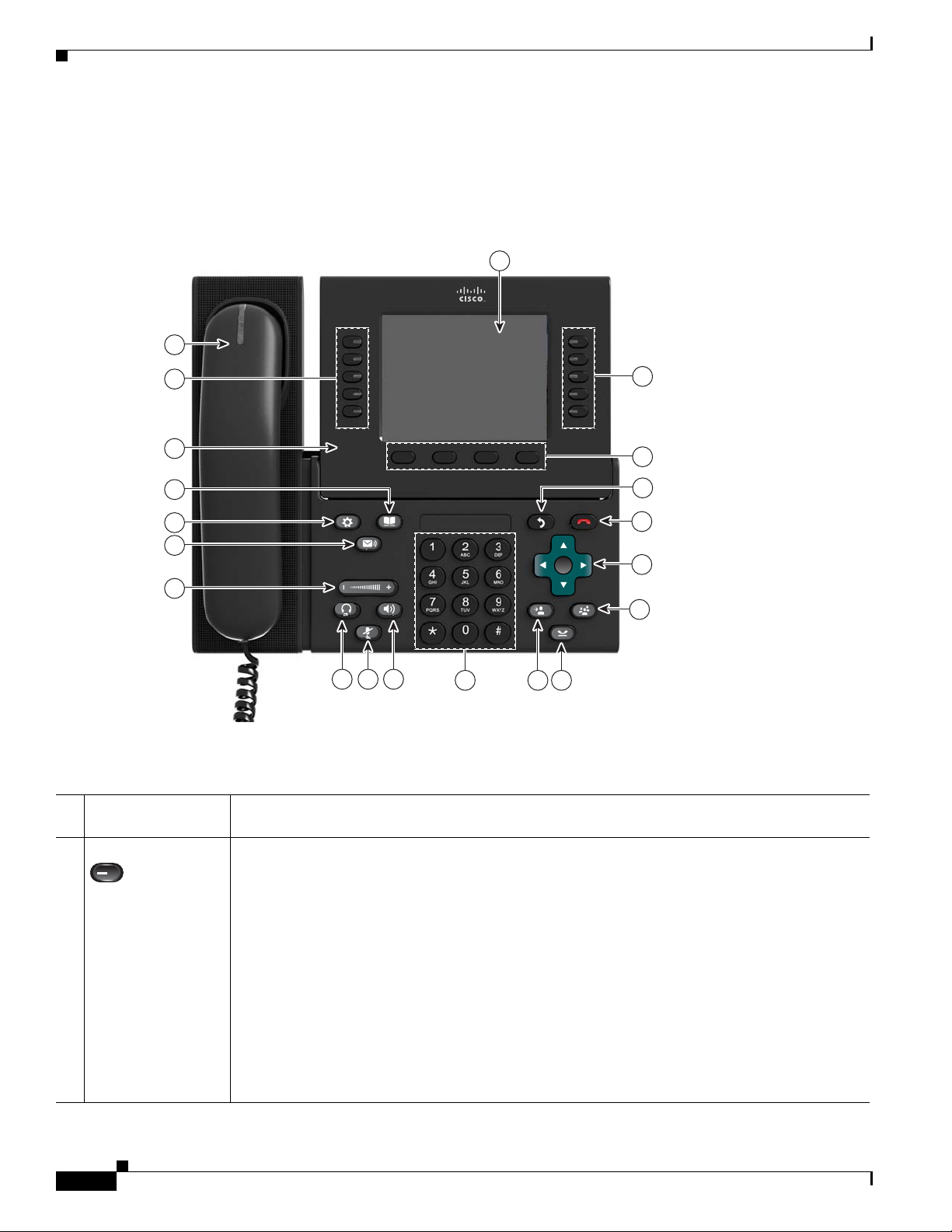
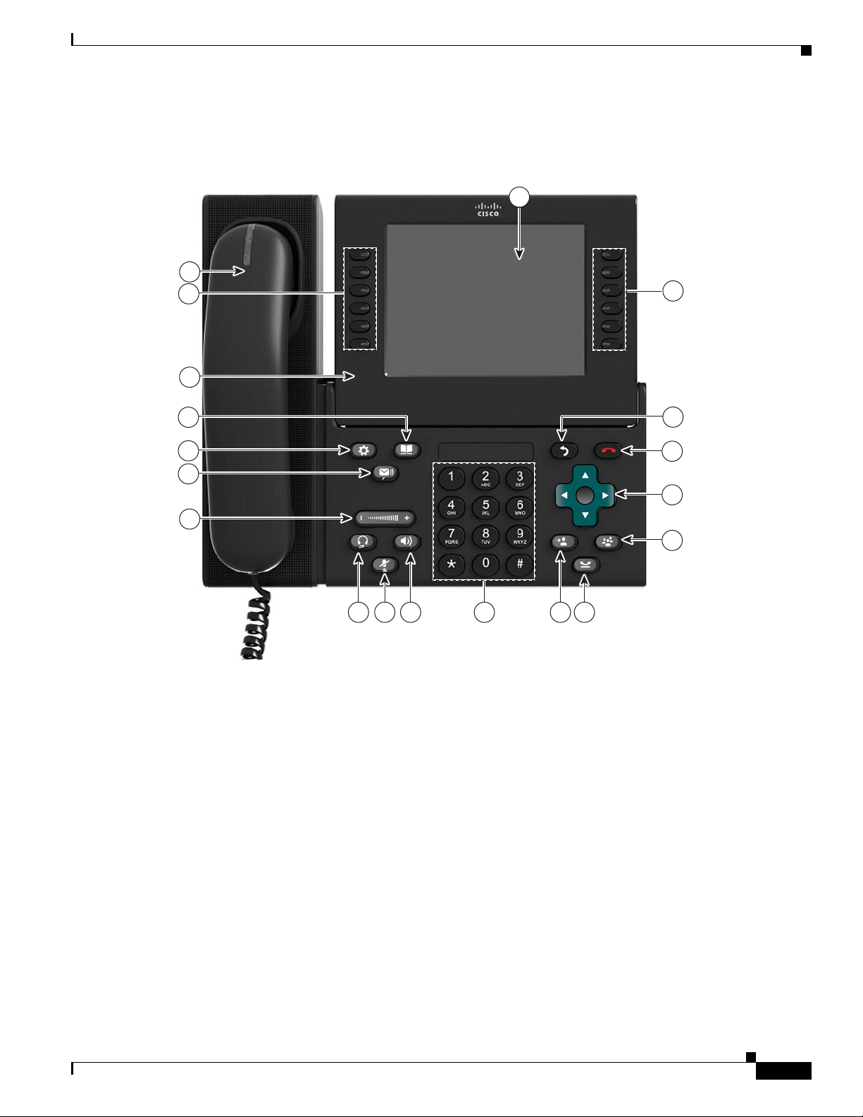
Figure 1-1 shows the main components of the Cisco Unified IP Phone 8961.
Figure 1-1 Cisco Unified IP Phone 8961
1
20
19
18
17
16
15
14
12 1113
10 9
8
2
3
4
5
6
7
194674
Ta ble 1- 1 describes the buttons on the Cisco Unified IP Phone 8961.
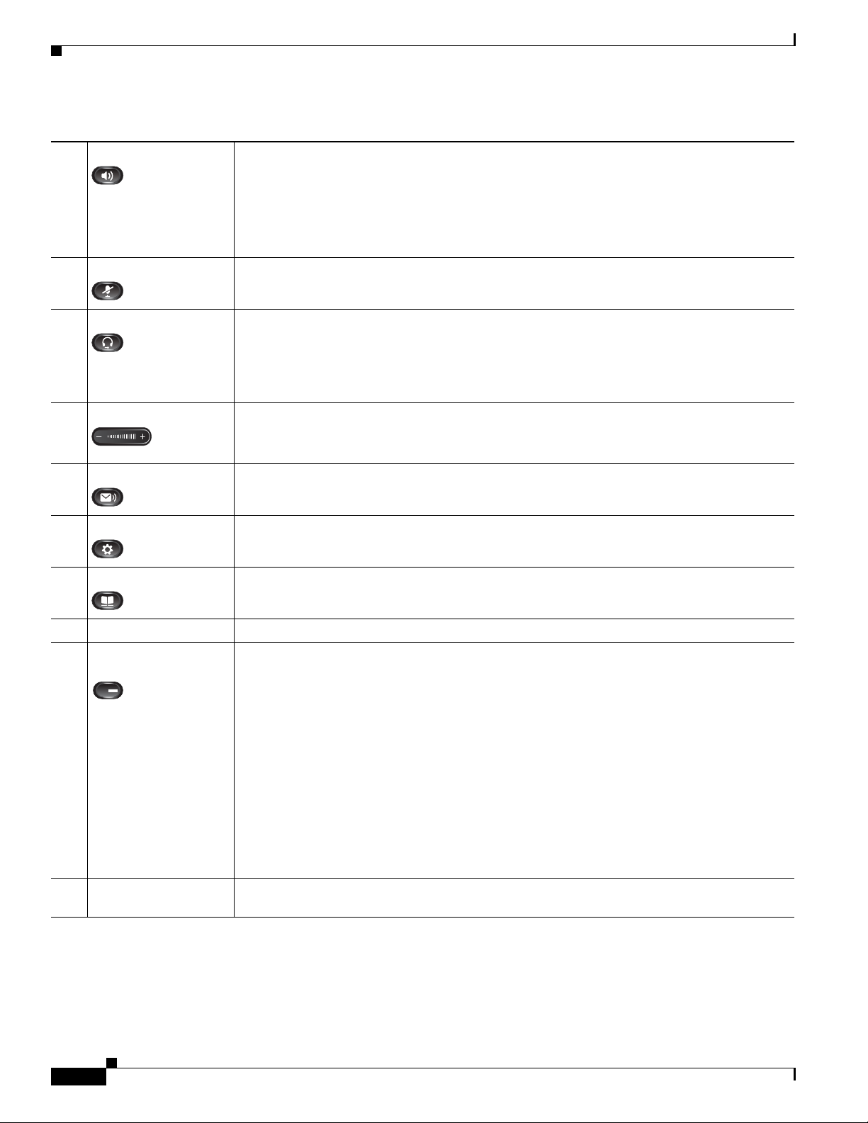
Table 1-1 Features on the Cisco Unified IP Phone 8961
Phone screen Shows information about your phone, including directory number, call information (for
1
example caller ID, icons for an active call or call on hold) and available softkeys.
Session buttons Each represents a call session and takes the default action for that session. For example, pressing
2
the session button for a ringing call answers the call, while pressing the session button for a held
call resumes the call.
Color LEDs reflect the call state. LEDs can flash (blink on and off rapidly), pulse (alternately
dim and brighten), or appear solid (glow without interruption).
• Flashing amber—Ringing call
• Solid green—Connected call or an outgoing call that is not yet connected
• Pulsing green—Held call
• Solid red—Shared line in-use remotely
• Pulsing red—Shared line call put on hold remotely (when Privacy is off)
(The position of session buttons may be reversed with that of programmable feature buttons on
phones using a locale with a right-to-left reading orientation, such as Hebrew and Arabic.)
1-2
Cisco Unified IP Phone 8961, 9951, and 9971 Administration Guide for Cisco Unified Communications Manager 8.5 (SIP)
OL-20861-01
Page 17
Chapter 1 An Overview of the Cisco Unified IP Phone
Understanding the Cisco Unified IP Phone 8961, 9951, and 9971
Table 1-1 Features on the Cisco Unified IP Phone 8961 (continued)
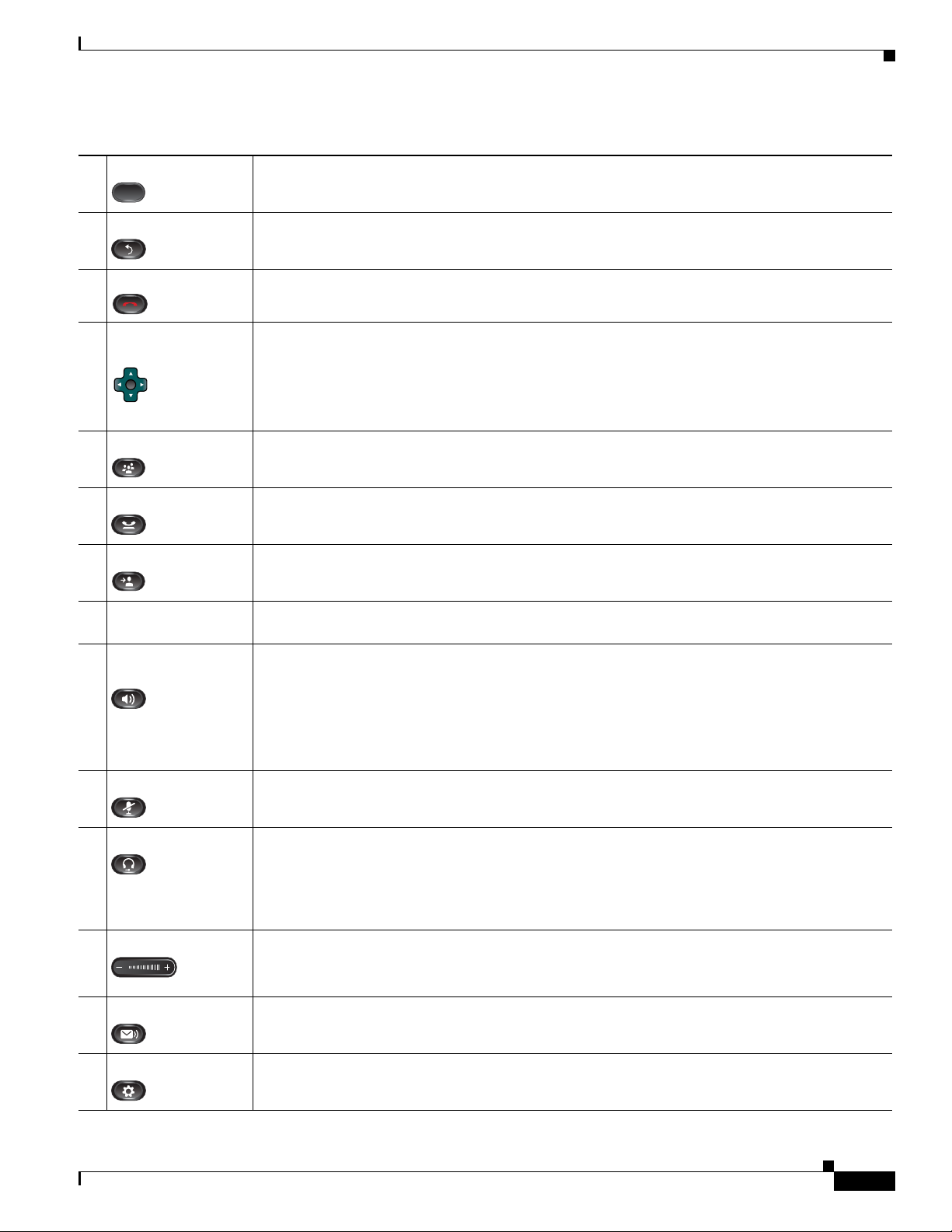
Softkey buttons Allow you to access the softkey options displayed on your phone screen.
3
Back button Returns to the previous screen or menu.
4
Release button Ends a connected call or session.
5
Navigation pad and
6
Select button
Conference button Creates a conference call.
7
Hold button Places a connected call on hold.
8
Transfer button Transfers a call.
9
Keypad Allows you to dial phone numbers, enter letters, and choose menu items (by entering the item
10
Speakerphone
11
button
Mute button Toggles the microphone on or off during a call. When the microphone is muted, the button is
12
The four-way Navigation pad allows you to scroll through menus, highlight items, and move
within a text input field.
The Select button (center of the Navigation pad) allows you to select a highlighted item, disable
the phone screen for cleaning, or enable the phone screen if it is in power-save mode.
The Select button is lit (white) when the phone is in power-save mode.
number).
Selects the speakerphone as the default audio path and initiates a new call, picks up an incoming
call, or ends a call. During a call, the button is lit green.
The speakerphone audio path does not change until a new default audio path is selected (for
example, by picking up the handset).
If external speakers are connected, the Speakerphone button selects them as the default audio
path.
lit red.
Headset button Selects the wired headset as the default audio path and initiates a new call, picks up an incoming
13
call, or ends a call. During a call, the button is lit green.
A headset icon in the phone screen header line indicates the headset is the default audio path.
This audio path does not change until a new default audio path is selected (for example, by
picking up the handset).
Volume button Controls the handset, headset, and speakerphone volume (off-hook) and the ringer volume
14
(on-hook).
Silences the ringer on the phone if an incoming call is ringing.
Messages button Auto-dials your voicemail system (varies by system).
15
Applications button Opens the Applications menu. Depending on how your system administrator sets up the phone,
16
use it to access applications such as call history, preferences, and phone information.
Cisco Unified IP Phone 8961, 9951, and 9971 Administration Guide for Cisco Unified Communications Manager 8.5 (SIP)
OL-20861-01
1-3
Page 18
Chapter 1 An Overview of the Cisco Unified IP Phone
Understanding the Cisco Unified IP Phone 8961, 9951, and 9971
Table 1-1 Features on the Cisco Unified IP Phone 8961 (continued)
Contacts button Opens the Contacts menu. Depending on how your system administrator sets up the phone, use
17
it to access personal directory, corporate directory, or call history.
Phone display Phone display that can be positioned to your preferred viewing angle.
18
Programmable
19
feature buttons
Handset with light
20
strip
Programmable feature buttons that correspond to phone lines, speed dials, and calling features.
Pressing a button for a phone line displays the active calls for that line. If you have multiple
lines, you might have an All Calls feature button that displays a consolidated list of calls from
all lines.
Color LEDs indicate the line state:
• Amber—Ringing call on this line
• Green—Active or held call on this line
• Red—Shared line in-use remotely
(The position of programmable feature buttons may be reversed with that of session buttons on
phones using a locale with a right-to-left reading orientation, such as Hebrew and Arabic.)
The handset light strip lights up to indicate a ringing call (flashing red) or a new voice message
(steady red).
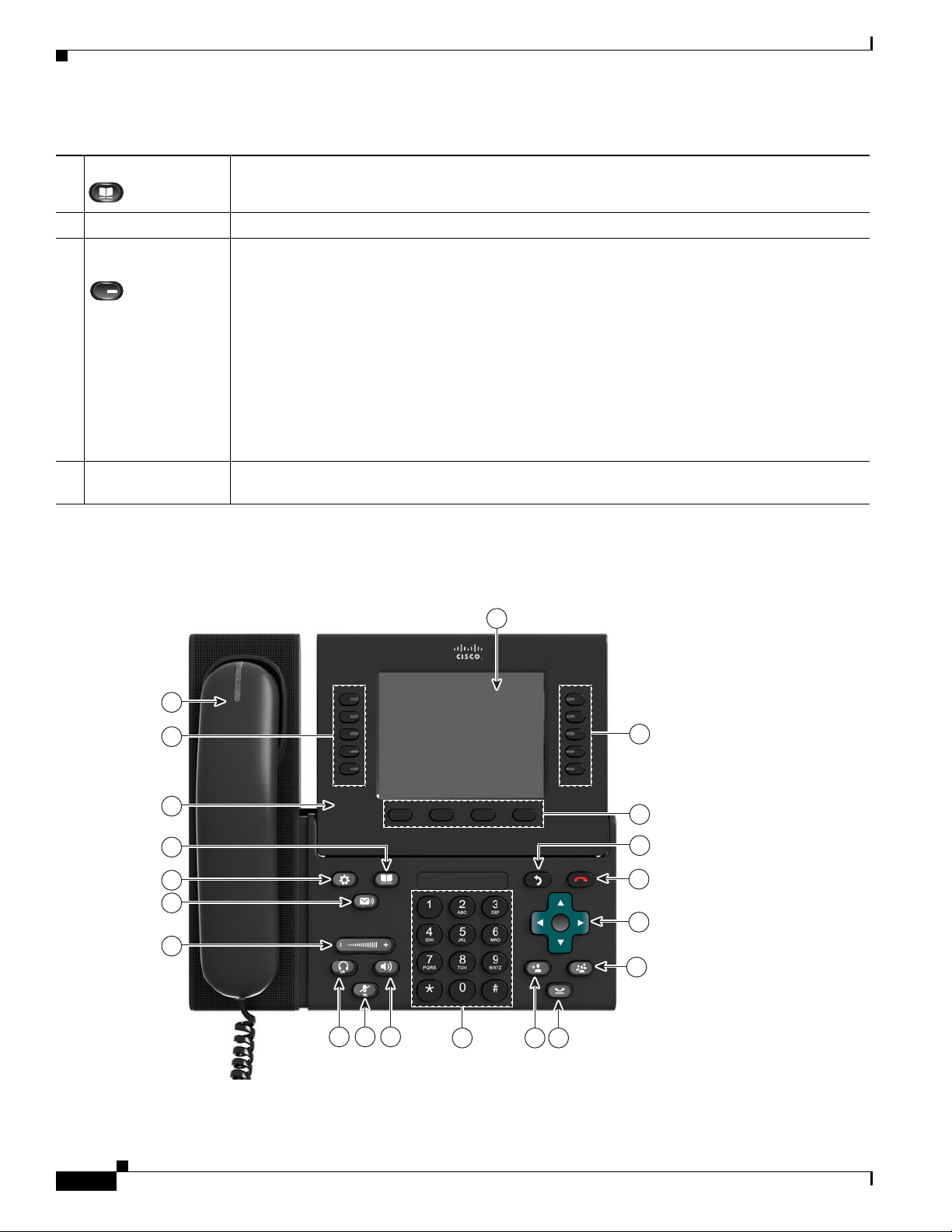
Figure 1-2 shows the main components of the Cisco Unified IP Phone 9951.
Figure 1-2 Cisco Unified IP Phone 9951
20
19
18
17
16
15
14
1
2
3
4
5
6
7
1-4
12 1113
Cisco Unified IP Phone 8961, 9951, and 9971 Administration Guide for Cisco Unified Communications Manager 8.5 (SIP)
10 9
8
194674
OL-20861-01
Page 19
Chapter 1 An Overview of the Cisco Unified IP Phone
Understanding the Cisco Unified IP Phone 8961, 9951, and 9971
Ta ble 1- 2 describes the buttons on the Cisco Unified IP Phone 9951.
Table 1-2 Features on the Cisco Unified IP Phone 9951
Phone screen Shows information about your phone, including directory number, call information (for
1
example caller ID, icons for an active call or call on hold) and available softkeys.
Session buttons Each represents a call session and takes the default action for that session. For example,
2
pressing the session button for a ringing call answers the call, while pressing the session
button for a held call resumes the call.
Color LEDs reflect the call state. LEDs can flash (blink on and off rapidly), pulse (alternately
dim and brighten), or appear solid (glow without interruption).
• Flashing amber—Ringing call
• Solid green—Connected call or an outgoing call that is not yet connected
• Pulsing green—Held call
• Solid red—Shared line in-use remotely
• Pulsing red—Shared line call put on hold remotely
(The position of session buttons may be reversed with that of programmable feature buttons
on phones using a locale with a right-to-left reading orientation, such as Hebrew and
Arabic.)
Softkey buttons Allow you to access the softkey options displayed on your phone screen.
3
Back button Returns to the previous screen or menu.
4
Release button Ends a connected call or session.
5
Navigation pad and
6
Select button
The four-way Navigation pad allows you to scroll through menus, highlight items, and move
within a text input field.
The Select button (center of the Navigation pad) allows you to select a highlighted item,
disable the phone screen for cleaning, or enable the phone screen if it is in power-save mode.
The Select button is lit (white) when the phone is in power-save mode.
Conference button Creates a conference call.
7
Hold button Places a connected call on hold.
8
Transfer button Transfers a call.
9
Keypad Allows you to dial phone numbers, enter letters, and choose menu items (by entering the
10
item number).
OL-20861-01
Cisco Unified IP Phone 8961, 9951, and 9971 Administration Guide for Cisco Unified Communications Manager 8.5 (SIP)
1-5
Page 20
Chapter 1 An Overview of the Cisco Unified IP Phone
Understanding the Cisco Unified IP Phone 8961, 9951, and 9971
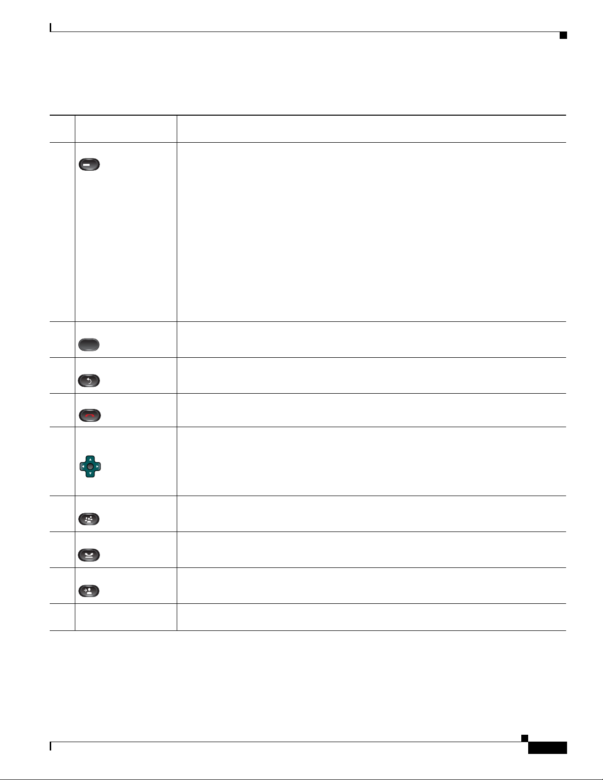
Table 1-2 Features on the Cisco Unified IP Phone 9951 (continued)
Speakerphone button Selects the speakerphone as the default audio path and initiates a new call, picks up an
11
incoming call, or ends a call. During a call, the button is lit green.
The speakerphone audio path does not change until a new default audio path is selected (for
example, by picking up the handset).
If external speakers are connected, the Speakerphone button selects them as the default
audio path.
Mute button Toggles the microphone on or off during a call. When the microphone is muted, the button
12
is lit red.
Headset button Selects the wired headset as the default audio path and initiates a new call, picks up an
13
incoming call, or ends a call. During a call, the button is lit green.
A headset icon in the phone screen header line indicates the headset is the default audio path.
This audio path does not change until a new default audio path is selected (for example, by
picking up the handset).
Volume button Controls the handset, headset, and speakerphone volume (off-hook) and the ringer volume
14
(on-hook).
Silences the ringer on the phone if an incoming call is ringing.
Messages button Auto-dials your voicemail system (varies by system).
15
Applications button Opens the Applications menu. Depending on how your system administrator sets up the
16
phone, use it to access applications such as call history, preferences, and phone information.
Contacts button Opens the Contacts menu. Depending on how your system administrator sets up the phone,
17
use it to access personal directory, corporate directory, or call history.
Phone display Phone display that can be positioned to your preferred viewing angle.
18
Programmable feature
19
buttons
Programmable feature buttons that correspond to phone lines, speed dials, and calling
features.
Pressing a button for a phone line displays the active calls for that line. If you have multiple
lines, you might have an All Calls feature button that displays a consolidated list of calls
from all lines.
Color LEDs indicate the line state:
• Amber—Ringing call on this line
• Green—Active or held call on this line
• Red—Shared line in-use remotely
(The position of programmable feature buttons may be reversed with that of session buttons
on phones using a locale with a right-to-left reading orientation, such as Hebrew and
Arabic.)
Handset with light
20
strip
The handset light strip lights up to indicate a ringing call (flashing red) or a new voice
message (steady red).
1-6
Cisco Unified IP Phone 8961, 9951, and 9971 Administration Guide for Cisco Unified Communications Manager 8.5 (SIP)
OL-20861-01
Page 21
Chapter 1 An Overview of the Cisco Unified IP Phone
Figure 1-3 shows the main components of the Cisco Unified IP Phone 9971.
Figure 1-3 Cisco Unified IP Phone 9971
19
18
17
Understanding the Cisco Unified IP Phone 8961, 9951, and 9971
1
2
16
15
14
13
3
4
5
6
711 1012 9 8
194675
OL-20861-01
Cisco Unified IP Phone 8961, 9951, and 9971 Administration Guide for Cisco Unified Communications Manager 8.5 (SIP)
1-7
Page 22

Chapter 1 An Overview of the Cisco Unified IP Phone
Understanding the Cisco Unified IP Phone 8961, 9951, and 9971
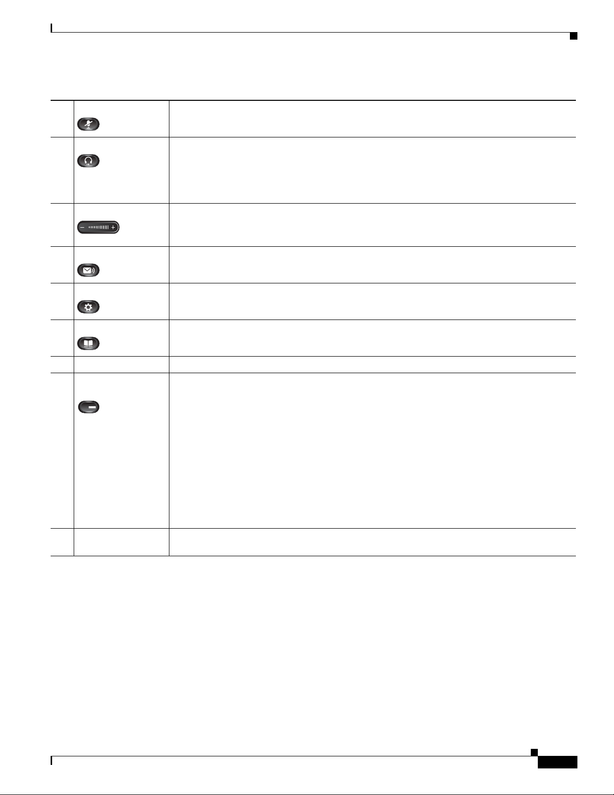
Table 1-3 describes the buttons on the Cisco Unified IP Phone 9971.
Table 1-3 Features on the Cisco Unified IP Phone 9971
Phone screen Shows information about your phone, including directory number, call information (for
1
example caller ID, icons for an active call or call on hold) and available softkeys.
Phone screen items, such as menu options and softkeys, are touch-sensitive.
Session buttons Each represents a call session and takes the default action for that session. For example,
2
pressing the session button for a ringing call answers the call, while pressing the session button
for a held call resumes the call.
Color LEDs reflect the call state. LEDs can flash (blink on and off rapidly), pulse (alternately
dim and brighten), or appear solid (glow without interruption).
• Flashing amber—Ringing call
• Solid green—Connected call or an outgoing call that is not yet connected
• Pulsing green—Held call
• Solid red—Shared line in-use remotely
• Pulsing red—Shared line call put on hold remotely
(The position of session buttons may be reversed with that of programmable feature buttons
on phones using a locale with a right-to-left reading orientation, such as Hebrew and Arabic.)
Back button Returns to the previous screen or menu.
3
Release button Ends a connected call or session.
4
Navigation pad and
5
Select button
The four-way Navigation pad allows you to scroll through menus, highlight items, and move
within a text input field.
The Select button (center of the Navigation pad) allows you to select a highlighted item,
disable the phone screen for cleaning, or enable the phone screen if it is in power-save mode.
The Select button is lit (white) when the phone is in power-save mode.
Conference button Creates a conference call.
6
Hold button Places a connected call on hold.
7
Transfer button Transfers a call.
8
Keypad Allows you to dial phone numbers, enter letters, and choose menu items (by entering the item
9
number).
Speakerphone
10
button
Selects the speakerphone as the default audio path and initiates a new call, picks up an
incoming call, or ends a call. During a call, the button is lit green.
The speakerphone audio path does not change until a new default audio path is selected (for
example, by picking up the handset).
If external speakers are connected, the Speakerphone button selects them as the default audio
path.
1-8
Cisco Unified IP Phone 8961, 9951, and 9971 Administration Guide for Cisco Unified Communications Manager 8.5 (SIP)
OL-20861-01
Page 23
Chapter 1 An Overview of the Cisco Unified IP Phone
Understanding the Cisco Unified IP Phone 8961, 9951, and 9971
Table 1-3 Features on the Cisco Unified IP Phone 9971 (continued)
Mute button Toggles the microphone on or off during a call. When the microphone is muted, the button is
11
lit red.
Headset button Selects the wired headset as the default audio path and initiates a new call, picks up an
12
incoming call, or ends a call. During a call, the button is lit green.
A headset icon in the phone screen header line indicates the headset is the default audio path.
This audio path does not change until a new default audio path is selected (for example, by
picking up the handset).
Volume button Controls the handset, headset, and speakerphone volume (off-hook) and the ringer volume
13
(on-hook).
Silences the ringer on the phone if an incoming call is ringing.
Messages button Auto-dials your voicemail system (varies by system).
14
Applications button Opens the Applications menu. Depending on how your system administrator sets up the
15
phone, use it to access applications such as call history, preferences, and phone information.
Contacts button Opens the Contacts menu. Depending on how your system administrator sets up the phone,
16
use it to access personal directory, corporate directory, or call history.
Phone display Phone display that can be positioned to your preferred viewing angle.
17
Programmable
18
feature buttons
Programmable feature buttons that correspond to phone lines, speed dials, and calling
features.
Pressing a button for a phone line displays the active calls for that line. If you have multiple
lines, you might have an All Calls feature button that displays a consolidated list of calls from
all lines.
Color LEDs indicate the line state:
• Amber—Ringing call on this line
• Green—Active or held call on this line
• Red—Shared line in-use remotely
(The position of programmable feature buttons may be reversed with that of session buttons
on phones using a locale with a right-to-left reading orientation, such as Hebrew and Arabic.)
Handset with light
19
strip
The handset light strip lights up to indicate a ringing call (flashing red) or a new voice message
(steady red).
OL-20861-01
Cisco Unified IP Phone 8961, 9951, and 9971 Administration Guide for Cisco Unified Communications Manager 8.5 (SIP)
1-9
Page 24

Chapter 1 An Overview of the Cisco Unified IP Phone
What Networking Protocols are Used?
What Networking Protocols are Used?
Cisco Unified IP Phones support several industry-standard and Cisco networking protocols required for
voice communication. Table 1 -4 provides an overview of the networking protocols that the
Cisco Unified IP Phone 8961, 9951, and 9971 support.
Table 1-4 Supported Networking Protocols on the Cisco Unified IP Phone
Networking Protocol Purpose Usage Notes
Bluetooth Bluetooth is a wireless personal area
network (WPAN) protocol that specifies
how devices communicate over short
distances.
Bootstrap Protocol
(BootP)
Cisco Audio Session
Tunnel (CAST)
Cisco Discovery Protocol
(CDP)
Cisco Peer-to-Peer
Distribution Protocol
(CPPDP)
Dynamic Host
Configuration Protocol
(DHCP)
BootP enables a network devi ce such as
the Cisco Unified IP Phone to discover
certain startup information, such as its IP
address.
The CAST protocol allows the Cisco
Unified IP Phones and associated
applications to discover and communicate
with the remote IP phones without
requiring changes to the traditional
signaling components such as Cisco
Unified CM and gateway s.
CDP is a device-discovery protocol that
runs on all Cisco-manufactured
equipment.
Using CDP, a device can advertise its
existence to other devices and receive
information about other devices in the
network.
CPPDP is a Cisco proprietary protocol
used to form a peer to peer hierarchy of
devices. This hierarchy is used to
distribute firmware files from peer devices
to their neighboring devices.
DHCP dynamically allocates and assigns
an IP address to network devices.
DHCP enables you to connect an IP phone
into the network and have the phone
become operational without your needing
to manually assign an IP address or to
configure additional network parameters.
Cisco Unified IP Phone 9951 and 9971 support
Bluetooth 2.1
—
The Cisco Unified IP Phone uses CAST as an
interface between CUVA and Unified CM using the
Cisco IP Phone as a SIP proxy.
The Cisco Unified IP Phone uses CDP to
communicate information such as auxiliary VLAN ID,
per port power management details, and Quality of
Service (QoS) configuration information with the
Cisco Catalyst switch.
CPPDP is used by the Peer Firmware Sharing
feature.
DHCP is enabled by default. If disabled, you must
manually configure the IP address, subnet mask,
gateway, and a TFTP server on each phone locally.
Cisco recommends that you use DHCP custom
option 150. With this method, you configure the
TFTP server IP address as the option value. For
additional supported DHCP configurations, go to
the Dynamic Host Configuration Protocol chapter
and the Cisco TFTP chapter in the Cisco Unified
Communications Manager System Guide.
Note If you cannot use option 150, you may try
using DHCP option 66.
1-10
Cisco Unified IP Phone 8961, 9951, and 9971 Administration Guide for Cisco Unified Communications Manager 8.5 (SIP)
OL-20861-01
Page 25

Chapter 1 An Overview of the Cisco Unified IP Phone
What Networking Protocols are Used?
Table 1-4 Supported Networking Protocols on the Cisco Unified IP Phone (continued)
Networking Protocol Purpose Usage Notes
Hypertext Transfer
Protocol (HTTP)
Hypertext Transfer
Protocol Secure (HTTPS)
IEEE 802.1X The IEEE 802.1X standard defines a
IEEE 802.11a/b/g The IEEE 802.11 standard specifies how
Internet Protocol (IP) IP is a messa ging protocol that addresses
HTTP is the standard way of transferring
information and moving documents across
the Internet and the web.
Hypertext Transfer Protocol Secure
(HTTPS) is a combination of the
Hypertext Transfer Protocol with the
SSL/TLS protocol to provide encryption
and secure identification of servers.
client-server-based access control and
authentication protocol that restricts
unauthorized clients from connecting to a
LAN through publicly accessible ports.
Until the client is authenticated, 802.1X
access control allows only Extensible
Authentication Protocol over LAN
(EAPOL) traffic through the port to which
the client is connected. After
authentication is successful, normal traffic
can pass through the port.
devices communication over a wireless
local area network (WLAN).
802.11a operates at the 5 GHz band and
802.11b and 802.11g operate at the 2.4
GHz band
and sends packets across the network.
Cisco Unified IP Phones use HTTP for the XML
services and for troubleshooting purposes
Web applications with both HTTP and HTTPS
support have two URLs configured. Cisco Unified
IP Phones that support HTTPS choose the HTTPS
URL.
The Cisco Unified IP Phone implements the IEEE
802.1X standard by providing suppo rt for the
following authentication methods: EAP-FAST,
EAP-TLS, and EAP-MD5.
When 802.1X authentication is enabled on the
phone, you should disable the PC port and voice
VLAN. Refer to the “Supporting 802.1X
Authentication on Cisco Unified IP Phon es” section
on page 1-22 for additional information.
(Cisco Unified IP Phone 9971 only) The 802.11
interface is a deployment option for cases when
Ethernet cabling is unavailable or undesirable.
To communicate using IP, network devices must
have an assigned IP address, subnet, and gatewa y.
Link Layer Discovery
Protocol (LLDP)
Cisco Unified IP Phone 8961, 9951, and 9971 Administration Guide for Cisco Unified Communications Manager 8.5 (SIP)
OL-20861-01
LLDP is a standardized network discovery
protocol (similar to CDP) that is supported
on some Cisco and third-party devices.
IP addresses, subnets, and gateways identificati ons
are automatically assigned if you are using the
Cisco Unified IP Phone with Dynamic Host
Configuration Protocol (DHCP). If you are not
using DHCP, you must manually assign these
properties to each phone locally.
The Cisco Unified IP Phone supports LLDP on the
PC port.
1-11
Page 26

Chapter 1 An Overview of the Cisco Unified IP Phone
What Networking Protocols are Used?
Table 1-4 Supported Networking Protocols on the Cisco Unified IP Phone (continued)
Networking Protocol Purpose Usage Notes
Link Layer Discovery
Protocol-Media Endpoint
Devices (LLDP-MED)
Real-Time Transport
Protocol (RTP)
Real-Time Control
Protocol (RTCP)
Session Description
Protocol (SDP)
Session Initiation Protocol
(SIP)
Transmission Control
Protocol (TCP)
Transport Layer Security TLS is a standard protocol for securing
LLDP-MED is an extension of the LLDP
standard developed for voice products.
RTP is a standard protocol for transporting
real-time data, such as interactive voice
and video, over data networks.
RTCP works in conjunction with RTP to
provide QoS data (such as jitter, latency,
and round trip delay) on RTP streams.
SDP is the portion of the SIP protocol that
determines which parameters are available
during a connection between two
endpoints. Conferences are established by
using only the SDP capabilities that are
supported by all endpoints in the
conference.
SIP is the Internet Engineering T ask Force
(IETF) standard for multimedia
conferencing over IP. SIP is an
ASCII-based application-layer control
protocol (defined in RFC 3261) that can be
used to establish, maintain, and terminate
calls between two or more endpoints.
TCP is a connection-oriented transport
protocol.
and authenticating communications.
The Cisco Unified IP Phone supports LLDP-MED
on th e S W p o r t t o communicate information such as:
• Voice VLAN configuration
• De vice disco very
• Power management
• Inv entory m anage ment
For more information about LLDP-MED support,
see the LLDP-MED and Cisco Discovery Protocol
white paper:
http://www.cisco.com/en/US/tech/tk652/tk701/tech
nologies_white_paper0900aecd804cd46d.shtml
Cisco Unified IP Phones use the RTP protocol to
send and receive real-time voice traffic from other
phones and gateways.
RTCP is disabled by default, but you can enable it
on a per phone basis by using Cis co Unified
Communications Manager.
SDP capabilities, such as codec types, DTMF
detection, and comfort noise, are normally
configured on a global basis by Cisco Unified
Communications Manager or Media Gateway in
operation. Some SIP endpoints may allow these
parameters to be configured on the endpoint itself.
Like other VoIP protocols, SIP is designed to
address the functions of signaling and session
management within a packet telephony network.
Signaling allows call information to be carried
across network boundaries. Session management
provides the ability to control the attributes of an
end-to-end call.
Cisco Unified IP Phones use TCP to connect to
Cisco Unified Communication s Manage r and to
access XML services.
When security is implemented, Cisco Unified IP
Phones use the TLS protocol when securely
registering with Cisco Unified Communications
Manager.
1-12
Cisco Unified IP Phone 8961, 9951, and 9971 Administration Guide for Cisco Unified Communications Manager 8.5 (SIP)
OL-20861-01
Page 27

Chapter 1 An Overview of the Cisco Unified IP Phone
What Features are Supported on the Cisco Unified IP Phone 8961, 9951, and 9971?
Table 1-4 Supported Networking Protocols on the Cisco Unified IP Phone (continued)
Networking Protocol Purpose Usage Notes
Trivial File Transfer
Protocol (TFTP)
User Datagram Protocol
(UDP)
Related Topics
• Understanding Interactions with Other Cisco Unified IP Telephony Products, page 2-1
• Understanding the Phone Startup Process, page 2-7
• Ethernet Setup Menu, page 7-4
TFTP allows you to transfer files over the
network.
On the Cisco Unified IP Phone, TFTP
enables you to obtain a configuration file
specific to the phone type.
UDP is a connectionless messaging
protocol for delivery of data packets.
TFTP requires a TFTP server in your network,
which can be automatically identified from the
DHCP server. If you want a phone to use a TFTP
server other than the one specified by the DHCP
server, you must manually assign the IP address of
the TFTP server by using the Network
Configuration menu on the phone.
For more information, go to the Cisco TFTP chapter
in the Cisco Unified Communications Manager
System Guide.
Cisco Unified IP Phones transmit and receive RTP
streams, which utilize UDP.
What Features are Supported on the Cisco Unified
IP
Phone 8961, 9951, and 9971?
Cisco Unified IP Phones function much like a digital business phone, allowing you to place and receive
phone calls. In addition to traditional telephony features, the Cisco Unified IP Phone includes features
that enable you to administer and monitor the phone as a network device.
This section includes the following topics:
• Feature Overview, page 1-13
• Configuring Telephony Features, page 1-14
• Configuring Network Parameters Using the Cisco Unified IP Phone, page 1-14
• Providing Users with Feature Information, page 1-15
Feature Overview
Cisco Unified IP Phones provide traditional telephony functionality, such as call forwarding and
transferring, redialing, speed dialing, conference calling, and voice messaging system access.
Cisco Unified IP phones also provide a variety of other features. For an overview of the telephony
features that the Cisco Unified IP Phone supports and for tips on configuring them, see the “Telephony
Features Available for the Cisco Unified IP Phone” section on page 8-2 .
As with other network devices, you must configure Cisco Unified IP Phones to prepare them to access
Cisco Unified Communications Manager and the rest of the IP network. By using DHCP , you have fewer
settings to configure on a phone, but if your network requires it, you can manually configure an IP
OL-20861-01
Cisco Unified IP Phone 8961, 9951, and 9971 Administration Guide for Cisco Unified Communications Manager 8.5 (SIP)
1-13
Page 28

What Features are Supported on the Cisco Unified IP Phone 8961, 9951, and 9971?
address, TFTP server, subnet information, and so on. For instructions on configuring the network
settings on the Cisco Unified IP Phones, see Chapter 7, “Configuring Settings on the Cisco Unified
IP Phone.”
Cisco Unified IP Phones can interact with other services and devices on your IP network to provide
enhanced functionality. For example, you can integrate Cisco Unified Communications Manager with
the corporate Lightweight Directory Access Protocol 3 (LDAP3) standard directory to enable users to
search for co-worker contact information directly from their IP phones. You can also use XML to enable
users to access information such as weather, stocks, quote of the day , and other web-based information.
For information about configuring such services, see the “Configuring Corporate and Personal
Directories” section on page 8-27 and the “Setting Up Services” section on page 8-32.
Finally, because the Cisco Unified IP Phone is a network device, you can obtain detailed status
information from it directly. This information can assist you with troubleshooting any problems users
might encounter when using their IP p hones. See Chapter 10, “Viewing Model Inform at ion, S t atus, and
Statistics on the Cisco Unified IP Phone,” for more information.
Related Topics
• Configuring Settings on the Cisco Unified IP Phone, page 7-1
• Configuring Features, Templates, Services, and Users, page 8-1
Chapter 1 An Overview of the Cisco Unified IP Phone
• Troubleshooting and Maintenance, page 12-1
Configuring Telephony Features
You can modify additional settings for the Cisco Unified IP Phone from Cisco Unified Communications
Manager Administration. Use this web-based application t o set up phone registration criteria and calling
search spaces, to configure corporate directories and services, and to modify phone button templates,
among other tasks. See the “Telephony Features Available for the Cisco Unified IP Phone” section on
page 8-2 and the Cisco Unified Communications Manager documentation for additional information.
For more information about Cisco Unified Communications Manager Administration, refer to
Cisco Unified Communications Manager documentation, including Cisco Unified Communications
Manager Administration Guide. You can also use the context-sensitive help available within the
application for guidance.
You can access Cisco Unified Communications Manager docume ntati on at thi s location :
http://www.cisco.com/en/US/products/sw/voicesw/ps556/tsd_products_support_series_home.html
You can access Cisco Unified Communications Manager Business Edition documentation at this
location:
http://www.cisco.com/en/US/products/ps7273/tsd_products_support_series_home.html
Related Topic
• Telephony Features Available for the Cisco Unified IP Phone, page 8-2
Configuring Network Parameters Using the Cisco Unified IP Phone
You can configure parameters such as DHCP, TFTP, and IP settings on the phone itself. You can also
obtain statistics about a current call or firmware versions on the phone.
Cisco Unified IP Phone 8961, 9951, and 9971 Administration Guide for Cisco Unified Communications Manager 8.5 (SIP)
1-14
OL-20861-01
Page 29

Chapter 1 An Overview of the Cisco Unified IP Phone
For more information about configuring features and viewing statistics from the phone, see Chapter 7,
“Configuring Settings on the Cisco Unified IP Phone” and see Chapter 10, “Viewing Model
Information, Status, and Statistics on the Cisco Unified IP Phone.”
Providing Users with Feature Information
If you are a system administrator, you ar e likely th e pr imary source of in format ion for Cisco Unified IP
Phone users in your network or company. To ensure that you distribute the most current feature and
procedural information, familiarize yourself with Cisco Unified IP Phone documentation. Make sure to
visit the Cisco Unified IP Phone web sit e:
http://www.cisco.com/en/US/products/ps10453/products_user_guide_list.html
From this site, you can view various user guid es.
In addition to providing documentation, it is important to inform users of available Cisco Unified IP
Phone features, including those specific to your company or network, and of how to access and
customize those features, if appropriate.
For a summary of some of the key information that phone users need their system administrators to
provide, see Appendix A, “Providing Information to Users Via a Website.”
Understanding Security Features for Cisco Unified IP Phones
Understanding Security Features for Cisco Unified IP Phones
Implementing security in the Cisco Unified Communications Manager system prevents identity theft of
the phone and Cisco Unified Communications Manager server, prevents data tampering, and prevents
call signaling and media stream tampering.
To alleviate these threats, the Cisco IP telephony network establishes and maintains secure (encrypted)
communication streams between a phone and the server, digitally signs files before they are transferred
to a phone, and encrypts media streams and call signaling between Cisc o Unified IP p hones.
The Cisco Unified IP Phone 8961, 9951, and 9971 use the Phone security profile, which defines whether
the device is nonsecure or secure. For information on applying the securit y profile to th e phone, refer t o
the Cisco Unified Communications Manager Security Guide.
If you configure security-related settings in Cisco Unified Communications Manager Administration,
the phone configuration file will contain sensitive information. To ensure the privacy of a configuration
file, you must configure it for encryption. For detailed in formation, ref er to the “Confi guring Encrypted
Phone Configuration Files” chapter in Cisco Unified Communications Manager Security Guide.
Ta ble 1- 5 shows where you can find information about security in this and other documents.
Table 1-5 Cisco Unified IP Phone and Cisco Unified Communications Manager Security Topics
Topic Reference
Detailed explanation of security, including set
up, configuration, and troubleshooting
information for Cisco Unified Communications
Manager and Cisco Unified IP Phon es
Security features supported on the Cisco
Unified IP Phone
Restrictions regarding security features See the “Security Restrictions” section on page 1-23
Refer to the Cisco Unified Communications Manager Security Guide.
See the “Overview of Supported Security Features” section on page 1-16
OL-20861-01
Cisco Unified IP Phone 8961, 9951, and 9971 Administration Guide for Cisco Unified Communications Manager 8.5 (SIP)
1-15
Page 30

Chapter 1 An Overview of the Cisco Unified IP Phone
Understanding Security Features for Cisco Unified IP Phones
Table 1-5 Cisco Unified IP Phone and Cisco Unified Communications Manager Security Topics (continued)
Topic Reference
Viewing a security profile name Table 1-6 provides an overview of the security features that the
Cisco Unified IP Phone 8961, 9951, and 9971 support. For more
information about these features and about Cisco Unified Communications
Manager and Cisco Unified IP Phone security, refer to the Cisco
Unified Communications Manager Security Guide.
Identifying phone calls for which security is
implemented
Extension Mobility HTTPS Support See the “What Networking Protocols are Used?” section on page 1-10
TLS connection
Security and the phone startup process See the “Understanding the Phone Startup Process” section on page 2-7
Security and phone configuration files See the “Adding Phones to the Cisco Unified Communications Manager
Changing the TFTP Server 1 or TFTP Server 2
option on the phone when security is
implemented.
Items on the Security Setup menu that you
access from the phone
Disabling access to a phone’s web pages See the “Enabl ing and Di sabling Web Page Access” section on page 11-3
Troubleshooting
Deleting the CTL file from the phone See the “Resetting the Cisco Unified IP Phone” section on page 12-15
Resetting or restoring the phone See the “Resetting the Cisco Unified IP Phone” section on page 12-15
802.1X Authentication for Cisco Unified IP
Phones
See the “Identifying Secure (Encrypted) Phone Calls” section on page 1-19
• See the “What Networking Protocols are Used?” section on page 1-10
• See the “Adding Phones to the Cisco Unified Communications
Manager Database” section on page 2-9
Database” section on page 2-9
See the “IPv4 Setup Menu Options” section on page 7-10
See the “Security Setup Menu” section on page 7-13
• See the “Troubleshooting Cisco Unified IP Phone Security” section on
page 12-9
• Refer to the Troubleshooting Gu ide for Cisco Unified Communications
Manager
See these sections:
• “Supporting 802.1X Authentication on Cisco Unified IP Phones”
section on page 1-22
• “Security Setup Menu” section on page 7-13
• “Status Menu” section on page 10-2
• “Troubleshooting Cisco Unified IP Phone Security” section on
page 12-9
Overview of Supported Security Features
Ta ble 1- 6 provides an overview of the security features that the Cisco Unified IP Phone 8961, 9951, and
9971 support. For more information about these features and about Cisco Unified Communications
Manager and Cisco Unified IP Phone security, refer to Cisco Unified Communications Manager
Security Guide.
Cisco Unified IP Phone 8961, 9951, and 9971 Administration Guide for Cisco Unified Communications Manager 8.5 (SIP)
1-16
OL-20861-01
Page 31

Chapter 1 An Overview of the Cisco Unified IP Phone
Understanding Security Features for Cisco Unified IP Phones
For information about current security settings on a phone, press and choose Administrator
Settings > Security Setup. For more information, see the “Security Setup Menu” section on page 7-13.
Table 1-6 Overview of Security Features
Feature Description
Image authentication Signed binary files (with the extension .sbn) prevent tampering with the firmware
image before it is loaded on a phone. Tampering with the image causes a phone to fail
the authentication process and reject the new image.
Image Encryption Encrypted binary files (with the extension .sebn) prevent tampering with the firmware
image before it is loaded on a phone.
Tampering with the image causes a phone to fail the authentication process and reject
the new image.
Customer-site certificate
installation
Device authentication Occurs between the Cisco Unified Communications Manager server and the phone
File authentication Validates digitally signed files that the phone downloads. The phone validates the
File encryption Encryption prevents sensitive information from being revealed while the file is in
Signaling Authentication Uses the TLS pro tocol to validate that no tampering has occurred to signaling packets
Manufacturing installed certificate Each Cisco Unified IP Phone contains a unique manufacturing installed certificate
Media encryption Uses SR TP to ensure that the media streams between supported devices proves secure
Each Cisco Unified IP Phone requires a unique certificate for device authentication.
Phones include a manufacturing installed certificate (MIC), but for addi tional security ,
you can specify in Cisco Unified Communications Manager Administration that a
certificate be installed by using the Certificate Authority Proxy Function (CAPF).
Alternatively , you can install a Locally Sign ificant Certificate (LSC) from the Security
Configuration menu on the phone. See the “Configuring Security on th e Cisco Unified
IP Phone” section on page 3-21 for more information.
when each entity accepts the certificate of the other entity. Determines whether a
secure connection between the phone and a Cisco Unified Communications Manager
should occur; and, if necessary, creates a secure signaling path between t he entiti es by
using TLS protocol. Cisco Unified Communications Man ager will not regist er ph ones
unless they can be authenticated by the Cisco Unified Communications Manager.
signature to make sure that file tampering did not occur after the file creation. Files that
fail authentication are not written to Flash memory on the phone. The phone rejects
such files without further processing.
transit to the phone. In addition the phone validat es the signat ure to make sure that file
tampering did not occur after the file creation. Files that fail authentication are not
written to Flash memory on the phone. The phone rejects such files without further
processing.
during transmission.
(MIC), which is used for device authentication. The MIC is a permanent unique proof
of identity for the phone, and allows Cisco Unified Communications Manager to
authenticate the phone.
and that only the intended device receives and reads the data. Includes creating a media
master key pair for the devices, delivering the keys to the devices, and securing the
delivery of the keys while the keys are in transport.
OL-20861-01
Cisco Unified IP Phone 8961, 9951, and 9971 Administration Guide for Cisco Unified Communications Manager 8.5 (SIP)
1-17
Page 32

Chapter 1 An Overview of the Cisco Unified IP Phone
Understanding Security Features for Cisco Unified IP Phones
Table 1-6 Overview of Security Features (continued)
Feature Description
CAPF (Certificate Authority Proxy
Function)
Security profiles Defines whether the phone is nonsecure, authenticated, encrypted, or protected. See
Encrypted configuration files Lets you ensure the privacy of phone configuration files.
Optional disabling of the web
server functionality for a phone
Phone hardening Additional security options, which you control from Cisco Unified Communications
Implements parts of the certificate generation procedure that are too
processing-intensive for the phone, and interacts with the phone for key generation and
certificate installation. The CAPF can be configured to request certificates from
customer-specified certificate authorities on behalf of the phone, or it can be
configured to generate certificates locally.
Ta ble 1- 6, which provides an overview of the security features that the Cisco Unified
IP Phone 9971 supports. For more information about these features and about
Cisco Unified Communications Manager and Cisco Unified IP Phone security, refer to
the Cisco Unified Communications Manager Security Guide.
For security purposes, you can prevent access to a phone’s web page (which displays
a variety of operational statistics for the phone) and user options pages. For more
information, see the “Enabling and Disabling Web Page Access” section on page 11-3.
Manager Administration:
• Disabling PC port
• Disabling Gratuitous ARP (GARP)
• Disabling PC Voice VLAN access
• Disabling acce ss to the Setting menus, or providing restricted access that allows
access to the Preferences menu and saving volume changes only
• Disabling acce ss to web pages for a phone
• Disabling Bluetooth Accessory Port
802.1X Authentication The Cisco Unified IP Phone can use 802.1X authentication to request and gain access
to the network. See the “Supporting 802.1X Authentication on Cisco Unified IP
Phones” section on page 1-22 for more information.
Secure SIP Failover for SRST After you configure an SRST reference for security and then reset the dependent
devices in Cisco Unified CM Administration, the TFTP server adds the SRST
certificate to the phone cnf.xml file and sends the file to the phone. A secure phone then
uses a TLS connection to interact with the SRST-enabled router.
Signaling encryption Ensures that all SCCP and SIP signaling messages that are sent between the device and
the Cisco Unified CM server are encrypted.
Related Topics
• Identifying Secure (Encrypted) Phone Calls, page 1-19
• Security Restrictions, page 1-23
1-18
Cisco Unified IP Phone 8961, 9951, and 9971 Administration Guide for Cisco Unified Communications Manager 8.5 (SIP)
OL-20861-01
Page 33

Chapter 1 An Overview of the Cisco Unified IP Phone
Understanding Security Profiles
All Cisco Unified IP Phones that support Cisco Unified Communications Manager use a security profile,
which defines whether the phone is nonsecure, authenticated, or encrypted. For information about
configuring the security profile and applying the profile to the phone, refer to Cisco Unified
Communications Manager Security Guide.
To view the security mode that is set for the phone, look at the Security Mode setting in the Security
Configuration menu. For more information, see the “Security Setup Menu” section on page 7-13.
Related Topics
• Identifying Secure (Encrypted) Phone Calls, page 1-19
• Security Restrictions, page 1-23
Identifying Secure (Encrypted) Phone Calls
When security is implemented for a phone, you can identify secure phone calls by icons on the phone
screen. You can also determine if the connected phone is secure and protected if a security tone plays at
the beginning of the call.
Understanding Security Features for Cisco Unified IP Phones
In a secure call, all call signaling and media streams are encrypted. A secure call offers a high level of
security, providing integrity and privacy to the call. When a call in progress is being encrypted, the call
progress icon to the right of the call duration timer in the phone screen changes to the following icon:
.
Note If the call is routed through non-IP call legs, for example, PSTN, the call may be nonsecure even though
it is encrypted within the IP network and has a lock icon associated with it.
In a secure call, a security tone plays at the beginning of a call to indicate that the other connected phone
is also receiving and transmitting secure audio and video (if video is inv olved). If your call is connected
to a non-secure phone, the security tone does not play.
Note Secure calling is supported for connections between two phones only . Some features, such as conference
calling, shared lines, and Extension Mobility are not available when secure calling is configured.
Related Topic
• Understanding Security Features for Cisco Unified IP Phones, page 1-15
• Security Restrictions, page 1-23
Establishing and Identifying Secure Conference Calls
OL-20861-01
You can initiate a sec ure conference call and monitor the security level of participants. A secure
conference call is established using this process:
1. A user initiates the conference from a secure phone.
2. Cisco Unified Comm unication s Manage r assigns a secure confere nce bridge to the call.
3. As participants are added, Cisco Unified Communications Manager verifies the security mode of
each phone and maintains the secure level for the conference.
Cisco Unified IP Phone 8961, 9951, and 9971 Administration Guide for Cisco Unified Communications Manager 8.5 (SIP)
1-19
Page 34

Understanding Security Features for Cisco Unified IP Phones
4. The phone displays the security level of the conference call. A secure conference displays icon
to the right of “Conference” on the phone screen.
Note There are interactions, restrictions, and limitations that affect the security level of the conference call
depending on the security mode of the participant’s phones and the availability of secure conference
bridges. See Table 1-7 and Table 1-8 for information about these interactions .
Establishing and Identifying Secure Calls
A secure call is established when your phone, and the phone on the other end, is configured for secure
calling. The other phone can be in the same Cisco IP network, or on a network outside the IP network.
Secured calls can only be made between two phones. Conference calls and other multiple-line calls are
not supported.
A secured call is established using this process:
1. A user initiates th e call from a secured phon e (secured secu rity mode).
2. The phone displays the icon (secure) on the phone screen. This icon indicates that the phone is
configured for secure calls, but this does not mean that the other connected phone is also secured.
Chapter 1 An Overview of the Cisco Unified IP Phone
3. A security tone plays if the call is connected to another secured phone, indicating that both ends of
the conversation are encrypted and secured. If the call is connected to a non-secured phone, then the
secure tone is not played.
Note Secured calling is supported for conversations between two phones. Some features, such as conference
calling, shared lines, and Cisco Extension Mobility are not available when secured calling is configured.
Call Security Interactions and Restrictions
Cisco Unified Communication s Manage r checks the phone security status when conferences are
established and changes the security indication for the conference or blocks the completion of the call
to maintain integrity and also security in the system.
call security levels when using Barge.
Table 1-7 Call Security Interactions When Using Barge
Initiator’s Phone
Security Level Feature Used Call Security Level Results of Action
Non-secure Barge Encrypted call Call barged and identified as non-secure call
Secure Barge Encrypted call Call barged and identified as secure call
Ta ble 1- 8 provides information about changes to conference security levels depending on the in itiat or’s
phone security level, the security levels of participants, and the availability of secure conference bridges.
Table 1-7 provides information about changes to
1-20
Cisco Unified IP Phone 8961, 9951, and 9971 Administration Guide for Cisco Unified Communications Manager 8.5 (SIP)
OL-20861-01
Page 35

Chapter 1 An Overview of the Cisco Unified IP Phone
Understanding Security Features for Cisco Unified IP Phones
Ta b l e 1-8 Security Restrictions with Conference Calls
Initiator’s Phone
Security Level Feature Used Security Level of Participants Results of Action
Non-secure Conference Secure Non-secure conference bridge
Non-secure conference
Secure Conference At least one member is
non-secure.
Secure Conference Secure. Secure conference bridge
Non-secure MeetMe Minimum security level is
encrypted
Secure MeetMe Minimum security level is
non-secure
Secure conference bridge
Non-secure conference
Secure encrypted level conference
Initiator receives message “Does not meet Security
Level, call rejected.”
Only secure conference bridge available and used
Conference accepts all calls
OL-20861-01
Cisco Unified IP Phone 8961, 9951, and 9971 Administration Guide for Cisco Unified Communications Manager 8.5 (SIP)
1-21
Page 36

Chapter 1 An Overview of the Cisco Unified IP Phone
Understanding Security Features for Cisco Unified IP Phones
Supporting 802.1X Authentication on Cisco Unified IP Phones
These sections provide information about 802.1X support on the Cisco Unified IP Phones:
• Overview, page 1-22
• Required Network Components, pa ge 1-22
• Best Practices—Requirements and Recommendations, page 1-22
Overview
Cisco Unified IP phones and Cisco Catalyst switches have traditionally used Cisco Discovery Protocol
(CDP) to identify each other and determine parameters such as VLAN allocation and inline power
requirements. However, CDP is not used to identify any locally attached PCs; therefore, Cisco Unified
IP Phones provide an EAPOL pass-through mechanism, whereby a PC locally attached to the IP phone,
may pass through EAPOL messages to the 8 02.1X auth enticator in the LAN switch. This prevents the
IP phone from having to act as the authe nticator, yet allows the LAN switch to authenticate a data
endpoint prior to accessing the network.
In conjunction with the EAPOL pass-through mechanism, Cisco Unified IP Phones provide a proxy
EAPOL-Logoff mechanism. In the event that the locally attached PC is disconnected from the IP phone,
the LAN switch would not see the physical link fail, because the link between the LAN switch and the
IP phone is maintained. T o avoid compromising networ k integrity , the IP phone sends an EAPOL-Logo ff
message to the switch, on behalf of the downstream PC, which triggers the LAN switch to clear the
authentication entry for the downstream PC.
The Cisco Unified IP phones also contain an 802.1X supplicant , in additio n to the EA POL pass-through
mechanism. This supplicant allows network administrators to control the connectivity of IP phones to
the LAN switch ports. The current release of the phone 802.1X supplicant uses the EAP-FAST,
EAP-TLS, and EAP-MD5 options for network authentication.
Required Network Components
Support for 802.1X authentication on Cisco Unified IP Phones requires several components, including:
• Cisco Unified IP Phone—The phone acts as the 802.1X supplicant, which initiates the request to
access the network.
• Cisco Secure Access Control Server (ACS) (or other third-party authentication server)—The
authentication server and the phone must both be configured with a shared secret that is used to
authenticate the phone.
• Cisco Catalyst Switch (or other third-party switch)—The switch must support 802.1X, so it can act
as the authenticator and pass the messages between the phone and the authentication server. When
the exchange is completed, the switch then grants or denies the phone access to the network.
Best Practices—Requirements and Recommendations
• Enable 802.1X Authentication—If you want to use the 802.1X standard to authenticate Cisco
Unified IP Phones, be sure that you have properly configured the other components before enabling
it on the phone. See the
more information.
“802.1X Authentication and Transaction Status” section on page 7-15 for
1-22
Cisco Unified IP Phone 8961, 9951, and 9971 Administration Guide for Cisco Unified Communications Manager 8.5 (SIP)
OL-20861-01
Page 37

Chapter 1 An Overview of the Cisco Unified IP Phone
• Configure PC Port—The 802.1X standard does not take into account the use of VLANs and thus
recommends that only a single device should be authenticated to a specific switch port. However,
some switches (including Cisco Catalyst switches) support multi-domain authentication. The switch
configuration determines whether you can connect a PC to the phone’s PC port.
–
Enabled—If you are using a switch that supports multi-domain authentication, you can enable
the PC port and connect a PC to it. In this case, Cisco Unified IP Phones support proxy
EAPOL-Logoff to monitor the authentication exchanges between the switch and the attached
PC. For more information about IEEE 802.1X support on the Cisco Catalyst switches, refer to
the Cisco Catalyst switch configuration guides at:
http://www.cisco.com/en/US/products/hw/switches/ps708/tsd_products_support_series_home.
html
–
Disabled—If the switch does not suppor t multi ple 802 .1X- compli ant devices on the same port ,
you should disable the PC Port when 802.1X authentication is enabl ed. See the
Menu” section on page 7-4 for more information. If you do not disable this port and
subsequently attempt to attach a PC to it, the switch will deny network access to both the phone
and the PC.
• Configure Voice VLAN—Because the 802.1X standard does not account for VLANs, you should
configure this setting based on the switch support.
Overview of Configuring and Installing Cisco Unified IP Phones
“Ethernet Setup
–
Enabled—If you are using a switch that supports multi-domain authenticatio n, you can continue
to use the voice VLAN.
–
Disabled—If the switch does not support multi-domain authentication, di sable the Voice VLAN
and consider assigning the port to the native VLAN. See the
page 7-4 for more information.
• Enter MD5 Shared Secret—If you disable 802.1X authentication or perform a factory reset on the
phone, the previously configured MD5 shared secret is deleted. See the
Transaction Status” section on page 7-15 for more information.
Security Restrictions
A user cannot barge into an encrypted call if the phone that is used to barge is not configured for
encryption. When barge fails in this case, a reorder tone (fast busy tone) plays on the phone on which
the user initiated the barge.
If the initiator phone is configured for encr yption, the barge ini tiator can barge into a nonsecure cal l from
the encrypted phone. After the bar ge occurs, Cisco Unified Communications Manager classifies the call
as nonsecure.
If the initiator phone is configured for encryption, the barge initiator can barge into an encrypted call,
and the phone indicates that the call is encrypted.
“Ethernet Setup Menu” section on
“802.1X Authentication and
Overview of Configuring and Installing Cisco Unified IP Phones
When deploying a new IP telephony system, system administrators and network administrators must
complete several initial configuration tasks to prepare the network for IP telephony service. For
information and a checklist for setting up and configuring a Cisco IP telephony network, go to the
System Configuration Overview chapter in Cisco Unified Communications Manager System Guide.
After you have set up the IP telephony system and configured system-wide features in Cisco Unified
Communications Manager, you can add IP phones to the system.
Cisco Unified IP Phone 8961, 9951, and 9971 Administration Guide for Cisco Unified Communications Manager 8.5 (SIP)
OL-20861-01
1-23
Page 38

Chapter 1 An Overview of the Cisco Unified IP Phone
Overview of Configuring and Installing Cisco Unified IP Phones
The following topics provide an overview of procedures for adding Cisco Unified IP Phones to your
network:
• Configuring Cisco Unified IP Phones in Cisco Unified Communications Manager, page 1-24
• Installing Cisco Unified IP Phones, page 1-28
Configuring Cisco Unified IP Phones in Cisco Unified Communications Manager
To add phones to the Cisco Unified Communications Manager database, you can use:
• Auto-registration
• Cisco Unified Communications Manager Administration
• Bulk Administration Tool (BAT)
• BAT and the Tool for Auto-Registered Phones Support (TAPS)
For more information about these choices, see the “Adding Phones to the Cisco Unified
Communications Manager Database” section on page 2-9.
For general information about configuring phones in Cisco Unified Communications Manager, refer to
the following documentation:
• Cisco Unified IP Phones, Cisco Unified Communications Manager System Guide
• Cisco Unified IP Phone Configuration, Cisco Unified Communications Manager Administ ration
Guide.
• Autoregistration Configuration, Cisco Unified Communications Manager Administration Guide.
• Cisco Unified Communications Manager Bulk Administration Guide.
1-24
Cisco Unified IP Phone 8961, 9951, and 9971 Administration Guide for Cisco Unified Communications Manager 8.5 (SIP)
OL-20861-01
Page 39

Chapter 1 An Overview of the Cisco Unified IP Phone
Overview of Configuring and Installing Cisco Unified IP Phones
Checklist for Configuring the Cisco Unified IP Phone 8961, 9951, and 9971 in Cisco Unified Communications Manager
Ta ble 1- 9 provides a checklist of configuration tasks for the Cisco Unified IP Phone 8961, 9951, and
9971 in Cisco Unified Communications Manager Administration. The list presents a suggested order to
guide you through the phone confi gurat ion process. Some t ask s are opti onal, depend ing on y our syst em
and user needs. For detailed procedures and information, refer to the sources in the list.
Table 1-9 Checklist for Configuring the Cisco Unified IP Phone 8961, 9951, and 9971 in Cisco Unified
Communications Manager
Task Purpose For More Information
1. Gather the following information about the phone:
• Phone Model
• MAC address
• Physica l location of t he phone
• Name or user ID of phone user
• Device pool
• Partition, calling search space, and loc ation
information
For more information, go to the “Cisco Unified IP
Phones chapter in the Cisco Unified Communications
Manager System Guide.
See the “Telephony Features Available for the Cisco
Unified IP Phone” section on page 8-2 .
• Number of lines and associated directory numbers
(DNs) to assign to the phone
• Cisco Unified Communications Manager user to
associate with the phone
• Phone usage information that affects phone
button template, phone features, IP Phone
services, or phone applications
Provides list of configuration requirements for setting
up phones.
Identifies preliminary configuration that you need to
perform before configuring individual phones, such as
phone button templates.
2. Verify that you have sufficient unit license for your
phone.
3. Customize phone button templates (if required).
Changes the number of line buttons, speed-dial
buttons or service URL buttons. You can add a
Privacy, All Calls, or Mobility button to meet user
needs.
For more information, go to the “Licensing” section in
the Cisco Unified Communications Manager System
Guide.
For more information, go to the Phone Button Template
Configuration chapter in the Cisco Unified
Communications Manager Administration Guide.
See the “Modifying Phone Button T emplates” section on
page 8-29.
OL-20861-01
Cisco Unified IP Phone 8961, 9951, and 9971 Administration Guide for Cisco Unified Communications Manager 8.5 (SIP)
1-25
Page 40

Chapter 1 An Overview of the Cisco Unified IP Phone
Overview of Configuring and Installing Cisco Unified IP Phones
Table 1-9 Checklist for Configuring the Cisco Unified IP Phone 8961, 9951, and 9971 in Cisco Unified
Communications Manager (continued)
Task Purpose For More Information
4. Add and configure the phone by completing the
required fields in the Phone Configuration window.
Required fields are indicated by an asterisk (*) next to
the field name; for example, MAC address and device
pool.
Adds the device with its defau lt settin gs to the Cisco
Unified Communications Manager database.
5. Add and configure directory numbers (lines) on the
phone by completing the required fields in the
Directory Number Configurati on wind ow. Required
fields are indicated by an asterisk (*) next to the field
name; for example, directory number and presence
group.
For more information, go to the Cisco Unified IP Phone
Configuration chapter in the Cisco Unified
Communications Manager Administration Guide.
For information about Product Specific Configuration
fields, refer to “?” Button Help in the Phone
Configuration window.
Note If you want to add both the phone and user to the
Cisco Unified Communicatio ns Manager
database at the same time, go to the User/Phone
Add Configuration chapter in the Cisco Unified
Communications Manager Administration
Guide.
For more information, go to the “Directory Number
Configuration” chapter in the Cisco Unified
Communications Manager Administration Guide.
See the “Telephony Features Available for the Cisco
Unified IP Phone” section on page 8-2 .
Adds primary and secondary directory numbers and
features associated with directory numbers to the
phone.
6. Configure speed-dial buttons and assign speed-dial
numbers (optional).
Adds speed-dial buttons and numbers.
Users can change speed-dial settings on their phones
by using Cisco Unified CM User Options.
7. Configure Cisco Unified IP Phone services and assign
services (optional).
Provides IP Phone services.
Users can add or change services on their phones by
using the Cisco Unified CM User Options.
Note Users can subscribe to the IP phone service
only if the Enterprise Subscription check box
is unchecked when the IP phone service is first
configured in Cisco Unified Communications
Manager Administration.
Note Some Cisco-provided default services are
classified as enterprise subscriptions, so the
user cannot add them through the user optio ns
pages. They are on the phone by default, and
they can only be removed from the phone if
you disable them in Cisco Unified
Communications Manager administration.
For more information, go to the “Configuring
Speed-Dial Buttons or Abbreviated Dialing” section in
the “Cisco Unified IP Phone Configuration” chapter in
the Cisco Unified Communications Manager
Administration Guide.
For more information, go to the “IP Phone Services
Configuration” chapter in the Cisco Unified
Communications Manager Administration Guide.
See the “Setting Up Services” section on page 8-32.
1-26
Cisco Unified IP Phone 8961, 9951, and 9971 Administration Guide for Cisco Unified Communications Manager 8.5 (SIP)
OL-20861-01
Page 41

Chapter 1 An Overview of the Cisco Unified IP Phone
Overview of Configuring and Installing Cisco Unified IP Phones
Table 1-9 Checklist for Configuring the Cisco Unified IP Phone 8961, 9951, and 9971 in Cisco Unified
Communications Manager (continued)
Task Purpose For More Information
8. Assign services to programmable buttons (optional).
Provides access to an IP phone service or URL.
9. Add user information by configuring required fields.
Required fields are indicated by an asterisk (*); for
example, User ID and last name.
Note Assign a password (for User Options web
pages) and PIN (for Cisco Extension Mobility
and Personal Directory)
Adds user information to the global directory for
Cisco Unified Communications Manager.
For more information, go to the “ Adding a Service URL
Button” section in the Cisco Unified IP Phone
Configuration chapter in the Cisco Unified
Communications Manager Administration Guide.
For more information, go to the End User Configuration
chapter in the Cisco Unified Communications Manager
Administration Guide.
See the “Adding Users to Cisco Unified
Communications Manager” section on page 8-33.
Note If your company uses a a Lightweight Directory
Access Protocol (LDAP) directory to store
information on users, you can install and
configure Cisco Unified Communications to use
your existing LDAP directory, refe r t o t h e
“Configuring Corporate Directories” section on
page 8-27.
10. Associate a user to a user group.
Assigns users a common list of roles and permissions
that apply to all users in a user group. Administrators
can manage user groups, roles, and perm issions to
control the level of access (and, therefore, the level of
security) for system users. For example, you must add
users to the standard Cisco CCM End Users group so
users can access Cisco Unified CM User Options.
11. Associate a user with a phone (optional).
Provides users with control over their phone such a
forwarding calls or adding speed-dial numbers or
services.
Note Some phones, such as those in conference
rooms, do not have an associated user.
Note If you want to add both the phone and user to the
Cisco Unified Communications Manager
database at the same time, go to the User/Phone
Add Configurations chapter in the Cisco Unified
Communications Manager Administration
Guide.
Refer to the following sectio ns in th e Cisco U nified
Communications Manager Administration Guide:
• “End User Configuration Settings” section in the
“End User Configuration” chapter.
• “Adding Users to a User Group” section in the “User
Group Configuration” chapter.
For more information, go to the “Asso ciating Devices to
an End User” section in the End User Configuration
chapter in the Cisco Unified Communications Manager
Administration Guide.
OL-20861-01
Cisco Unified IP Phone 8961, 9951, and 9971 Administration Guide for Cisco Unified Communications Manager 8.5 (SIP)
1-27
Page 42

Overview of Configuring and Installing Cisco Unified IP Phones
Installing Cisco Unified IP Phones
After you have added the phones to th e Cisco Unified Communications Manager database, you can
complete the phone installation. You (or the phone users) can install the phone at the users’s location.
The Cisco
directions for connecting the phone handset, cables, and other accessories.
Note Before you install a phone, even if it is new, upgrade the phone to the current firmware image. For
information about upgrading, refer to the Readme file for your phone, which is located at:
http://tools.cisco.com/support/downloads/go/Redirect.x?mdfid=278875240
After the phone is connected to the network, the phone startup process begins, and the phone registers
with Cisco Unified Communications Manager. To finish installing the phone, configure the network
settings on the phone depending on whether you enable or disable DHCP service.
If you used auto-registration, you need to update the specific configuration information for the phone
such as associating the phone with a user, changing the button table, or directory number.
Unified IP Phone Installation Guide, which is provided on the cisco.com web site, provides
Chapter 1 An Overview of the Cisco Unified IP Phone
Checklist for Installing the Cisco Unified IP Phone 8961, 9951, and 9971
Table 1-10 provides an overview and checklist of installation tasks for the Cisco Unified IP Phone 8961,
9951, and 9971. The list presents a suggested order to guide you through the phone installation. Some
tasks are optional, depending on your system and user needs. For detailed procedures and information,
refer to the sources in the list.
Table 1-10 Installation Checklist for the Cisco Unified IP Phone 8961, 9951, and 9971
Task Purpose For More Information
1. Choose the power source for the phone:
• Power over Ethernet (PoE)
• External power supply
Determines how the phone receives power.
Note The Cisco Unified IP Phone 9971, when being used in a
WLAN environment, requires an external power supply.
2. Assemble the phone, adjust phone placement, and connect the
network cable. (If you are using the Cisco Unified IP Phone 9971
in a WLAN environment, refer to Task 5.)
Locates and installs the phone in the network.
3. Monitor the phone startup process.
Adds primary and secondary directory numbers and features
associated with directory numbers to the phone.
See the “Providing Power to the Cisco
Unified IP Phone” section on page 2-3.
See the “Installing the Cisco Unified IP
Phone” section on page 3-11.
See the “Connecting the Footstand” section
on page 3-19.
See the “Verifying the Phone Startup
Process” section on page 3-21.
1-28
Verifies that phone is configured properly.
Cisco Unified IP Phone 8961, 9951, and 9971 Administration Guide for Cisco Unified Communications Manager 8.5 (SIP)
OL-20861-01
Page 43

Chapter 1 An Overview of the Cisco Unified IP Phone
Overview of Configuring and Installing Cisco Unified IP Phones
Table 1-10 Installation Checklist for the Cisco Unified IP Phone 8961, 9951, and 9971 (continued)
Task Purpose For More Information
4. If you choose to deploy the Cisco Unified IP Phone 9971 on a
wireless network, skip to Task 5.
See the “Configuring Startup Network
Settings” section on page 3-21.
If you are configuring the ethernet network settings on the phone
for an IP network, you can set up an IP address for the phone by
either using DHCP or manually entering an IP address.
Using DHCP—To enable DHCP and allow the DHCP server to
automatically assign an IP address to the Cisco Unified IP Phone
and direct the phone to a TFTP server, press Applications and
choose Administrator Settings > Network Setup > Ethernet
Setup > IPv4 Setup and:
• To enable DHCP, set DHCP Enabled to Yes. DHCP is enabled
by default.
• To use an alternate TFTP server, set Alternate TFTP Server to
Yes, and enter the IP address for the TFTP Server.
Note Consult with the network administrator to determine
whether you need to assign an alternative TFTP server
instead of using the TFTP server assigned by DHCP.
Without DHCP—You must configure the IP address, subnet mask,
TFTP server, and default router locally on the phone. Press
Applications and choose > Administrator Settings > Network
Setup > Ethernet Setup > IPv4 Setup:
To disable DHCP and manually set an IP address:
a. Set DHCP Enabled to No.
See the “Ethernet Setup Menu” section on
page 7-4.
b. Enter the static IP address for phone.
c. Enter the subnet mask.
d. Enter the default router IP addresses.
e. Set Alternate TFTP Server to Yes, and enter the IP address for
TFTP Server 1.
You must also enter the domain name where the phone resides.
Press Applications and choose Administrator Settings >
Network Setup> Ethernet Setup.
5. (Cisco Unified IP Phone 9971 only)
If you choose to deploy the phone on the wireless network, you
must configure the following:
• Configure the wireless network.
• Enable wireless LAN for phones on Cisco Unified
Communications Administration.
• Configure a wireless network profile on the phone.
Note The wireless LAN on the phone does not activate when
there are ethernet cables connected on the phone.
See Chapter 6, “Understanding the VoIP
Wireless Network.”
OL-20861-01
Cisco Unified IP Phone 8961, 9951, and 9971 Administration Guide for Cisco Unified Communications Manager 8.5 (SIP)
1-29
Page 44

Chapter 1 An Overview of the Cisco Unified IP Phone
Terminology Information
Table 1-10 Installation Checklist for the Cisco Unified IP Phone 8961, 9951, and 9971 (continued)
Task Purpose For More Information
6. Make calls with the Cisco Unified IP Phone.
Verifies that the phone and features work correctly.
7. Provide information to end users about how to us e their phones and
how to configure their phone options.
Ensures that users have adequate information to successfully use
their Cisco Unified IP Phones.
Refer to the Cisco Unified IP Phone 8961,
9951, and 9971 User Guide for Cisco
Unified Communications Manager.
See Appendix A, “Providing Information
to Users Via a Website.”
Terminology Information
Ta ble 1- 1 1 highlights some of the differences in terminolo gy found in the Cisco Unified IP Phone 8961,
9951, and 9971 User Guide and the Cisco Unified IP Phone 8961, 9951, and 9971 Administration Guide
and Cisco Unified Communications Administration Guide.
Table 1-11 Terminology Differences
User Guide Administration Guide
Line Status Busy Lamp Field (BLF)
Message Indicators Message Waiting Indicator (MWI) or Message Waiting Lamp
Programmable Feature Button Programmable Button or Programmable Line Key (PLK)
Voicemail System Voice Messaging System
1-30
Cisco Unified IP Phone 8961, 9951, and 9971 Administration Guide for Cisco Unified Communications Manager 8.5 (SIP)
OL-20861-01
Page 45

CHAP T E R
2
Preparing to Install the Cisco Unified IP Phone on Your Network
Cisco Unified IP Phones enable you to communicate by using voice over a data network. To provide this
capability, the IP Phones depend upon and interact with several other key Cisco Unifie d IP Telephony
components, including Cisco Unified Communications Manager.
This chapter focuses on the interactions between the Cisco Unified IP Phone 8961, 9951, and 9971 and
Cisco Unified Communications Manager, DNS and DHCP servers, TFTP servers, and switches. It also
describes options for powering phon es.
For related information about voice and IP communications, refer to this URL:
http://www.cisco.com/en/US/products/sw/voicesw/index.html
This chapter provides an overview of the interaction between the Cisco Unified IP Phone and other key
components of the Voice over IP (VoIP) network. It includes the following topics:
• Understanding Interactions with Other Cisco Unified IP Telephony Products, page 2-1
• Providing Power to the Cisco Unified IP Phone, page 2-3
• Understanding Phone Configuration Fi les, page 2-6
• Understanding the Phone Startup Process, page 2-7
• Adding Phones to the Cisco Unified Communications Manager Database, page 2-9
• Determining the MAC Address for a Cisco Unified IP Phone, page 2-13
Understanding Interactions with Other Cisco Unified IP Telephony Products
T o function in the IP telephony network, the Cisco Unified IP Phone must be connected to a networking
device, such as a Cisco Catalyst switch. You must also register the Cisco Unified IP Phone with a Cisco
Unified Communications Manager system before sending and receiving calls.
This section includes the following topics:
• Understanding How the Cisco Unified IP Phone Interacts with Cisco Unified Communications
Manager, page 2-2
• Understanding How the Cisco Unified IP Phone Interacts with the VLAN, page 2-2
Cisco Unified IP Phone 8961, 9951, and 9971 Administration Guide for Cisco Unified Communications Manager 8.5 (SIP)
OL-20861-01
2-1
Page 46

Chapter 2 Preparing to Install the Cisco Unified IP Phone on Your Network
Understanding Interactions with Other Cisco Unified IP Telephony Products
Understanding How the Cisco Unified IP Phone Interacts with Cisco Unified Communications Manager
Cisco Unified Communications M anager is a n open and industry-standard call processing system.
Cisco Unified Communications M anager soft ware sets up and tears do wn calls b etween ph ones,
integrating traditional PBX functionality wit h the corporate IP network. Cisco Unified Communications
Manager manages the components of the IP telephony system, such as the phones, the access gateways,
and the resources necessary for features such as call conferencing and route planni ng. Cisco U nified
Communications Manager also provides:
• Firmware for phones
• Configuration file, CTL, and Identity Trust List (ITL) files via the TFTP service
• Phone registration
• Call preservation, so that a media session continues if signaling is lost between the primary
Communications Manager and a phone
For information about configuring Cisco Unified Communications Manager to work with the IP devices
described in this chapter, go to the Cisco Unified IP Phone Configuration chapter in the
Cisco Communications Manager Administration Guide.
For an overview of security functionality for the Cisco Unified IP Phone, see the “Understanding
Security Features for Cisco Unified IP Phones” section on page 1-15.
Note If the Cisco Unified IP Phone model that you want to configure does not appear in the Phone Type
drop-down list in Cisco Unified Communicati ons Manager Administration, go to th e following URL and
install the latest support patch for your version of Cisco Unified
http://www.cisco.com/kobayashi/sw-center/sw-voice.shtml
Related Topic
• Telephony Features Available for the Cisco Unified IP Phone, page 8-2
Communications Manager:
Understanding How the Cisco Unified IP Phone Interacts with the VLAN
The Cisco Unified IP Phone 8961, 9951, and 9971 have an internal Ethernet switch, enabling forwarding
of packets to the phone, and to the Computer (access) port and the Network port on the back of the phone.
If a computer is connected to the Computer (access) port, the computer and the phone share the same
physical link to the switch and share the same port on the switch. This shared physical link has the
following implications for the VLAN configuration on the network:
• The current VLANs might be configured on an IP subnet basis. However, additional IP addresses
might not be available to assign the phone to the same subnet as other devices connected to the same
port.
• Data traffic present on the VLAN supporting phones might reduce the quality of Voice-over-IP
traffic.
• Network security may indicate a need to isolate the VLAN voice traffic from the VLAN data traf fic.
You can resolve these issues by isolating the voice traffic onto a separate VLAN. The switch port that
the phone is connected to would be configured to have separate VLANs for carrying:
2-2
Cisco Unified IP Phone 8961, 9951, and 9971 Administration Guide for Cisco Unified Communications Manager 8.5 (SIP)
OL-20861-01
Page 47

Chapter 2 Preparing to Install the Cisco Unified IP Phone on Your Network
Providing Power to the Cisco Unified IP Phone
• Voice traffic to and from the IP phone (auxiliary VLAN on the Cisco Catalyst 6000 series, for
example)
• Data traffic to and from the PC connected to the switch through the Computer (access) Port of the
IP phone (native VLAN)
Isolating the phones on a separate, auxiliary VLAN increases the quality of the voice traffic and allows
a large number of phones to be added to an existing network where there are not enough IP addresses
for each phone.
For more information, refer to the documentation included with a Cisco switch. You can also access
switch information at this URL:
http://cisco.com/en/US/products/hw/switches/index.html
Related Topics
• Understanding the Phone Startup Process, page 2-7
• Ethernet Setup Menu, page 7-4
Providing Power to the Cisco Unified IP Phone
The Cisco Unified IP Phone 8961, 9951, and 9971 can be powered with external power or with Power
over Ethernet (PoE). External power is provided through a separate power supply. PoE is provided by a
switch through the Ethernet cable attached to a phone.
Note When you install a phone that is powered with external power, connect the power supply to the phone
and to a power outlet before you connect the Ethernet cable to the phone. When you remove a phone that
is powered with external power, disco nnect the Ethernet cable from the phone before you disconnect the
power supply.
The following sections provide more information about powering a phone:
• Power Guidelines, page 2-4
• Power Outage, page 2-4
• Reducing Power Consumption on the Phone, page 2-4
• Power Negotiation over LLDP, page 2-5
• Obtaining Additional Information About Power, page 2-5
OL-20861-01
Cisco Unified IP Phone 8961, 9951, and 9971 Administration Guide for Cisco Unified Communications Manager 8.5 (SIP)
2-3
Page 48

Chapter 2 Preparing to Install the Cisco Unified IP Phone on Your Network
Providing Power to the Cisco Unified IP Phone
Power Guidelines
Table 2-1 provides guidelines for powering the Cisco Unified IP Phone 8961, 9951, and 9971.
Table 2-1 Guidelines for Powering the Cisco Unified IP Phone 8961, 9951, and 9971
Power Type Guidelines
External power—Provided
through the CP-PWR-CUBE-4=
external power supply.
External power—Provided
through the Cisco Unified IP
Phone Power Injector.
PoE power—Provided by a
switch through the Ethernet
cable attached to the phone.
The Cisco Unified IP Phone 8961, 9951, and 9971 use the CP-PWR-CUBE-4 power
supply.
Note You must use the CP-PWR-CUBE-4 when you deploy the Cisco Unified IP phone
9971 on a wireless Network.
The Cisco Unified IP Phone Power Injector may be used with any Cisco Unified IP Phone.
Functioning as a midspan device, the injector delivers inline power to the attached phone.
The Cisco Unified IP Phone Power Injector is connected between a switch port and the IP
Phone, and supports a maximum cable length of 100m between the unpower ed switch and
the IP Phone.
• Cisco Unified IP Phone 8961, 9951, and 9971 support IEEE 802.3af Class 3 power on
signal pairs and spare pairs.
• Cisco Unified IP Phone 8961, 9951, and 9971 support IEEE 802.3at for external
add-on devices.
• To ensure uninterruptible operation of the phone, make sure that the switch has a
backup power supply.
• Make sure that the CatOS or IOS version running on your switch supports your
intended phone deployment. Refer to the documentati on for your switch for operating
system version information.
External power—Provided
through inline power patch
panel WS-PWR-PANEL
The inline power patch panel WS-PWR-PANEL is compatible with the Cisco Unified
IP Phone 8961, 9951, and 9971.
Power Outage
Your accessibility to emergency service through the phone is dependent on the phone being powered. If
there is an interruption in the power supply, Service and Emergency Calling Service dialing will not
function until power is restored. In the case of a power failure or disruption, you may need to reset or
reconfigure equipment before using the Service or Emergency Calling Service dialing.
Reducing Power Consumption on the Phone
You can reduce the amount of energy that the Cisco Unified IP Phone consumes by scheduling when the
phone goes into power save mode. In power save m ode, the backlight on the screen is not lit when the
phone is not in use. The phone remains in power save mode for the scheduled duration or until the user
lifts the handset or presses any button. In the Phone Configuration page on Cisco Unified
Communications Administration, configure the following parameters.
• Days Display Not Active—Specify the days that the backlight remains inactive.
• Display on Time—Schedule the time of day that the backlight automatically activates. on the days
listed in the off schedule.
2-4
Cisco Unified IP Phone 8961, 9951, and 9971 Administration Guide for Cisco Unified Communications Manager 8.5 (SIP)
OL-20861-01
Page 49

Chapter 2 Preparing to Install the Cisco Unified IP Phone on Your Network
• Display on Duration—Indicates the length of time that the backlight is active once the backlight is
enabled by the programmed schedule
• Display Idle Timeout—Defines the period of user inactivity on the phone before the backlight is
turned off.
Power Negotiation over LLDP
The phone and the switch negotiate the power that the ph one can consume. Cisco Unified IP Phone 8961,
9951, 9971 operate at multiple power settings, which lowers their consumption when less power is
available.
After a phone reboots, the switch l ocks to one protoco l (CDP or LLDP) fo r powe r ne gotiat ion. It locks
to the first protocol (containing a power Threshold Limit Value (TLV)) that the phone transmits. If the
system administrator disables that protocol on the phone, it cannot power up any accessori es because the
switch does not respond to power requests in the other protocol.
Cisco recommends that Power Negotiation always be en abled (default) when connecting to a switch that
supports power negotiation.
If disabled, the switch may disconnect power to the phone. If the switch does not support power
negotiation, then disable the Power Negotiation feature before you power up accessories over PoE.
When the Power Negotiation feature is disabled, the phone can power the accessories up to 12.9W.
Providing Power to the Cisco Unified IP Phone
Note When CDP and Power Negotiation are disabled, the phone can power the accessories up to 15.4W.
To enable or disable power negotiation, see Table 8-1 , “ Telephony Features for the Cisco Unified IP
Phone”.
Obtaining Additional Information About Power
For related information about power, refer to the documents shown in Tab le 2-2. These documents
provide information about the following topics:
• Cisco switches that work with Cisco Unified IP Phones
• The Cisco IOS releases that support bidirectional power negotiation
• Other requirements and restrictions regarding power
Table 2-2 Related Documentation for Power
Document Topics URL
Cisco Unified IP Phone Power
Injector
PoE Solutions http://www.cisco.com/en/US/netsol/ns340/ns394/ns147/ns412/net
Cisco Catalyst Switches http://cisco.com/en/US/products/hw/switches/index.html
Integrated Service Routers http://www.cisco.com/en/US/products/hw/routers/index.html
Cisco IOS Software http://www.cisco.com/en/US/products/sw/iosswrel/products_ios_
http://www.cisco.com/en/US/products/ps6951/index.html
working_solutions_package.html
cisco_ios_software_category_home.html
OL-20861-01
Cisco Unified IP Phone 8961, 9951, and 9971 Administration Guide for Cisco Unified Communications Manager 8.5 (SIP)
2-5
Page 50

Chapter 2 Preparing to Install the Cisco Unified IP Phone on Your Network
Understanding Phone Configuration Files
Understanding Phone Configuration Files
Configuration files for a phone are stored on the TFTP server and define parameters for connecting to
Cisco Unified Communicati ons Mana ger. In general, any time you make a change in Cisco Unified
Communications Manager that requires the phone to be reset, a change is automatically made to the
phone’s configuration file.
Configuration files also contain information about which i mage load the phone should be running. If this
image load differs from the one currently loaded on a phone, the phone contacts the TFTP server to
request the required load files.
A phone accesses a default configuration file named XmlDefault.cnf.xml from the TFTP server when
the following conditions exist:
• You have enabled auto-registration in Cisco Unified Communications Manager
• The phone has not been added to the Cisco Unified Communications Manager database
• The phone is registering for the first time
Note If the device security mode in the configuration file is set to Authenticated or Encrypted, but the phone
has not received a CTL or ITL file, the phone trie s four times to obtain the file so it can register securely.
If auto registration is not enabled and the phone has not been added to the Cisco Unified
Communications Manager database, the phone registration request will be rejected and display a blank
screen.
If the phone has registered before, the phone will access the configuration file named
SEPmac_address.cnf.xml, where mac_address is the MAC address of the phone.
The filenames are derived from the MAC address and description fiel ds in the Phon e Config uration
window of Cisco Unified Communications Manager Administration. The MAC address uniquely
identifies the phone.
2-6
Cisco Unified IP Phone 8961, 9951, and 9971 Administration Guide for Cisco Unified Communications Manager 8.5 (SIP)
OL-20861-01
Page 51

Chapter 2 Preparing to Install the Cisco Unified IP Phone on Your Network
Understanding the Phone Startup Process
Understanding the Phone Startup Process
When connecting to the VoIP network, the Cisco Unified IP Phone 8961, 9951, and 9971 go through a
standard startup process that is described in
configuration, not all of these steps may occur on your Cisco Unified IP Phone.
Table 2-3 Cisco Unified IP Phone Startup Process
Task Purpose Related Topics
1. Obtain power from the switch.
If a phone is not using external power, th e switch provides in-line power
through the Ethernet cable attached to the phone.
2. (For a Cisco Unified IP Phone 9971 in a wireless LAN only) Scanning
for an access point.
The Cisco Unified IP Phone scans the RF coverage area with its radio.
The phone searches its network profiles and scans for access points that
have a matching SSID and authentication type. The phone associates
with the access point with the highest RSSI that matches with its
network profile.
3. (For a Cisco Unified IP Phone 9971 in a wireless LAN only)
Authenticating with the access point.
The Cisco Unified IP Phone begins the authentication process:
• If set for Open, then any device can authenticate to the access
point. For added security, static WEP encryption might optionally
be used.
Table 2-3. Depending on your specific network
• Ad ding Phones to the C isco
Unified Communications Manager
Database, page 2-9.
• Resolving Startup Problems,
page 12-1.
• Interacting with Cisco Unified
Wireless APs, page 6-8.
• Authentication Methods,
page 6-11.
• If set to Shared Key, the phone encrypts the challenge text using
the WEP key and the access point must verify that the WEP key
was used to encrypt the challenge text before network access is
available.
• If set for LEAP or EAP-FAST, then the user name and password
are authenticated by the RADIUS server before network access is
available. For more information about the name and password
authentication, see “WLAN Setup Menu” section on page 7-7.
• If set for Auto (AKM), the phone looks for an access point with
one of the following key management options enabled:
–
WPA, WPA2, or CCKM—The username and password are
authenticated by the RADIUS server before network access is
available.
–
WPA-Pre-shared key, WPA2-Pre-shared key—The phone
authenticates with the access point using the pre-shared key.
OL-20861-01
Cisco Unified IP Phone 8961, 9951, and 9971 Administration Guide for Cisco Unified Communications Manager 8.5 (SIP)
2-7
Page 52

Chapter 2 Preparing to Install the Cisco Unified IP Phone on Your Network
Understanding the Phone Startup Process
Table 2-3 Cisco Unified IP Phone Startup Process (continued)
Task Purpose Related Topics
4. Load the stored phone image.
The Cisco Unified IP Phone has non-volatile Flash memory in which it
stores firmware images and user-defined preferences. At startup, the
phone runs a bootstrap loader that loads a phone image stored in Flash
memory. Using this image, the phone initializes its software and
hardware.
5. Configure the VLAN.
If the Cisco Unified IP Phone is connected to a Cisco Catalyst switch,
the switch next informs the phone of the voice VLAN defined on the
switch. The phone needs to know its VLAN membership before it can
proceed with the Dynamic Host Configuration Protocol (DHCP)
request for an IP address.
6. Obtain an IP address.
If the Cisco Unified IP Phone is using DHCP to obtain an IP address,
the phone queries the DHCP server to obtain one. If you are no t using
DHCP in your network, you must assign static IP addresses to each
phone locally.
7. Requesting the CTL file.
The TFTP server stores the CTL file. This file contains the certificates
necessary for establishing a secure connection between the phone and
Cisco Unified CM.
8. Requesting the ITL file.
The phone requests the ITL file after it requests the CTL file. The ITL
file contains the certificates of the entities that the phone can trust. The
certificates are used for authenticating a secure connection with the
servers or authenticating a digital signature signed by the servers. The
ITL file is supported on the Cisco Unified CM 8.5 and later.
9. Access a TFTP server.
• Resolving Startup Problems,
page 12-1.
• Ethernet Setup Menu, page 7-4.
• Resolving Startup Problems,
page 12-1.
• Ethernet Setup Menu, page 7-4.
• Resolving Startup Problems,
page 12-1.
Refer to Cisco Unified
Communications Manager Security
Guide, Configuring the Cisco CTL
Client.
See the “Preparing to Install the Cisco
Unified IP Phone on Your Network”
chapter.
See the “Troubleshooting and
Maintenance” chapter.
• Ethernet Setup Menu, page 7-4.
2-8
In addition to assigning an IP address, the DHCP server directs the
Cisco Unified IP Phone to a TFTP Server. If the phone has a statically
• Resolving Startup Problems,
page 12-1.
defined IP address, you must configure the TFTP server locally on the
phone; the phone then contacts the TFTP server directly.
Note You can also assign an alternative TFTP server to use instead of
the one assigned by DHCP.
Cisco Unified IP Phone 8961, 9951, and 9971 Administration Guide for Cisco Unified Communications Manager 8.5 (SIP)
OL-20861-01
Page 53

Chapter 2 Preparing to Install the Cisco Unified IP Phone on Your Network
Adding Phones to the Cisco Unified Communications Manager Database
Table 2-3 Cisco Unified IP Phone Startup Process (continued)
Task Purpose Related Topics
10. Request the configuration file.
The TFTP server has configuration files, which define parameters for
connecting to Cisco Unified Communications Manager and other
information for the phone.
11. Contact Cisco Unified CM
The configuration file defines how the Cisco U nified IP Phone
communicates with Cisco Unified CM and provides a phone with its
load ID. After obtaining the file from the TFTP server, the phone
attempts to make a connection to the highest priority Cisco Unified CM
on the list.
If the security profile of the phone is configured for secure signaling
(encrypted or authenticated), and the Cisco Unified CM is set to secure
mode, the phone makes a TLS connection. Otherwise, it makes a
nonsecure TCP connection.
• Ad ding Phones to the C isco
Unified Communications Manager
Database, page 2-9.
• Resolving Startup Problems,
page 12-1.
See the “Preparing to Install the Cisco
Unified IP Phone on Your Network”
chapter.
See the “Troubleshooting and
Maintenance” chapter.
If the phone was manually added to the database, Cisco
Unified Communications Manager identifies the phone. If the phone
was not manually added to the database and auto-registr ation is enabled
in Cisco Unified Communications Manager, the phone attempts to
auto-register itself in the Cisco Unified Communications Manager
database.
Note Autoregistration is disabled when you configure the CTL client.
In this case, the phone must be manually added to the Cisco
Unified CM database.
Adding Phones to the Cisco Unified Communications Manager
Database
Before installing the Cisco Unified IP phone, you must choose a method for adding phones to the
Cisco Unified Communication s Manage r database. These sections describe the methods:
• Adding Phones with Auto-Registration, page 2-10
• Adding Phones with Auto-Registration and TAPS, page 2-11
• Adding Phones with Cisco Unified Communications Manager Administration, page 2-12
• Adding Phones Using BAT Phone Template, page 2-12
OL-20861-01
Cisco Unified IP Phone 8961, 9951, and 9971 Administration Guide for Cisco Unified Communications Manager 8.5 (SIP)
2-9
Page 54

Adding Phones to the Cisco Unified Communications Manager Database
Table 2-4 provides an overview of these methods for adding phones to the Cisco Unified
Communications Manager database.
Table 2-4 Methods for Adding Phones to the Cisco Unified Communications Manager
Database
Requires MAC
Method
Address? Notes
Auto-registration No Results in automatic assignment of directory numbers
Auto-registration with
No Requires auto-registration and the Bulk Administration
TAPS
Using the Cisco Unified
Yes Requires phones to be added individually
Communications Manager
Administration
Using BAT Y es Allows for simultaneous registration of multiple phones
Chapter 2 Preparing to Install the Cisco Unified IP Phone on Your Network
Tool (BAT); updates information in the Cisco Unified
IP Phone and in Cisco Unified Communications
Manager Administration
Adding Phones with Auto-Registration
By enabling auto-registration before you begin installing phones, you can:
• Add phones without first gathering MAC addresses from the phones.
• Automatically add a Cisco Unified IP Phone to the Cisco Unified Communications Manager
database when you physically connect the phone to your IP telephony network. During
auto-registration, Cisco
directory number to the phone.
• Quickly enter phones into the Cisco Unified Communications Manager database and modify any
settings, such as the directory numbers, from Cisco
• Move auto-registered phones to new locations and assign them to different device pools without
affecting their directory numbers.
Note Cisco recommends you use auto-registration to add less than 100 phones to your network. To add more
than 100 phones to your network, use the Bulk Administration Tool (BAT). See the
Using BAT Phone Template” section on page 2-12.
Auto-registration is disabled by default. In some cases, you might not want to use auto-registration; for
example, if you want to assign a specific directory number to the ph one, or use a secure connecti on with
Cisco Unified CM as described in Cisco Unified CM Security Guide. For information about enabling
auto-registration, go to the “Enabling Aut o-Regist ratio n ” section in the Cisco Unified Communications
Manager Administration Guide.
Unified Communications Manager assigns the next available sequential
Unified Communications Manager.
“Adding Phones
2-10
Related Topics
• Adding Phones with Auto-Registration and TAPS, page 2-11
• Adding Phones with Cisco Unified Communications Manager Administration, page 2-12
• Adding Phones Using BAT Phone Template, page 2-12
Cisco Unified IP Phone 8961, 9951, and 9971 Administration Guide for Cisco Unified Communications Manager 8.5 (SIP)
OL-20861-01
Page 55

Chapter 2 Preparing to Install the Cisco Unified IP Phone on Your Network
Adding Phones to the Cisco Unified Communications Manager Database
Adding Phones with Auto-Registration and TAPS
You can add phones with auto-registration and TAPS, the Tool for Auto-Registered Phones Support,
without first gathering MAC addresses from phones.
TAPS works with the Bulk Administration Tool (BAT) to update a batch of phones that were already
added to the Cisco Unified Communications Manager database with dummy MAC addresses. Use TAPS
to update MAC addresses and download pre-defined configurations for phones.
Note Cisco recommends you use auto-registration and TAPS to add less than 100 phones to your network. T o
add more than 100 phones to your network, use the Bulk Administration Tool (BAT). See the
Phones Using BAT Phone Template” section on page 2-12.
T o implement TAPS, you or the end-user dial a T APS directory number and follow voice prompts. When
the process is complete, the phone will have downloaded its directory number and other settings, and the
phone will be updated in Cisco Unified Communications Manager Administration with the correct MAC
address.
Auto-registration must be enabled in Cisco Unified Communications Manager Administration
(System > Cisco Unified CM) for TAPS to function.
“Adding
Note When you configure the cluster for mixed mode through the Cisco CTL client, auto-registration is
automatically disabled. When you configure the cluster for non-secure mode through the Cisco CTL
client, auto-registration is not enabled automatically.
For more information, refer to the Cisco Unified Communications Manager Bulk Administration Guide.
Related Topics
• Adding Phones with Auto-Registration, page 2-10
• Adding Phones with Cisco Unified Communications Manager Administration, page 2-12
• Adding Phones Using BAT Phone Template, page 2-12
OL-20861-01
Cisco Unified IP Phone 8961, 9951, and 9971 Administration Guide for Cisco Unified Communications Manager 8.5 (SIP)
2-11
Page 56

Chapter 2 Preparing to Install the Cisco Unified IP Phone on Your Network
Adding Phones to the Cisco Unified Communications Manager Database
Adding Phones with Cisco Unified Communications Manager Administration
You can add phones individually to the Cisco Unified Communications Manager database by using
Cisco Unified Communications Manager Administration. To do so, you first need to obtain the MAC
address for each phone.
For information about determining a MAC address, see the “Determining the MAC Address for a Cisco
Unified IP Phone” section on page 2-13.
After you have collected MAC addresses, in Cisco Unified Communications Manager Administration,
choose Device > Phone and click Add New to begin.
For complete instructions and conceptual information about Cisco Unified Communications Manager,
go to the “Cisco Unified Communications Manager Overview” chapter in the Cisco Unified
Communications Manager System Guide.
Related Topics
• Adding Phones with Auto-Registration, page 2-10
• Adding Phones with Auto-Registration and TAPS, page 2-11
• Adding Phones Using BAT Phone Template, page 2-12
Adding Phones Using BAT Phone Template
The Cisco Unified Communications Bulk Administration Tool (BAT) enables you to perform batch
operations including registration on multiple phones.
To add phones using BAT only (not in conjunction with TAPS), you must obtain the appropriate MAC
address for each phone.
For information about determining a MAC address, see the “Determining the MAC Address for a Cisco
Unified IP Phone” section on page 2-13.
For detailed instructions about adding phones using Bulk Administration menu, refer to the Cisco
Unified Communications Manager Bulk Administration Guide, chapter Inserting Phones.
To add a phone to the Cisco Unified Communications Manager, follow these steps:
Procedure
Step 1 From Cisco Unifi ed Commu nications Manager, choose Bulk Administration > Phones > Phone
Template.
Step 2 Click Add New.
Step 3 Choose a Phone Type and click Next.
Step 4 Enter the details of phone specific parameters like Device Pool, Phone Button Template, Device Security
Profile and so on.
Step 5 Click Save.
Step 6 From Cisco Unifi ed Commu nications Manager, choose Device > Phone > Add New to add a phone
using an existing BAT phone template.
2-12
Cisco Unified IP Phone 8961, 9951, and 9971 Administration Guide for Cisco Unified Communications Manager 8.5 (SIP)
OL-20861-01
Page 57

Chapter 2 Preparing to Install the Cisco Unified IP Phone on Your Network
Determining the MAC Address for a Cisco Unified IP Phone
For more information about using BAT, refer to the Cisco Unified Communications Manager Bulk
Administration Guide. For more information about creating of BAT Phone Templates, see the Cisco
Unified Communications Manager Bulk Administration Guide, Phone Template.
Related Topics
• Adding Phones with Auto-Registration, page 2-10
• Adding Phones with Auto-Registration and TAPS, page 2-11
• Adding Phones with Cisco Unified Communications Manager Administration, page 2-12
Determining the MAC Address for a Cisco Unified IP Phone
Several procedures described in this manual require you to determine the MAC address of a
Cisco Unified IP Phone. Yo u can determine a phone’s MAC address in these ways:
• From the phone, press the Applications button and choose Phone Information and look at the
MAC
Address field.
• Look at the MAC label on the back of the phone.
• Display the web page for the phone and click the Device Information hyperlink.
For information about accessing the web page, see the “Accessing the Web Page for a Phone”
section on page 11-2.
OL-20861-01
Cisco Unified IP Phone 8961, 9951, and 9971 Administration Guide for Cisco Unified Communications Manager 8.5 (SIP)
2-13
Page 58

Determining the MAC Address for a Cisco Unified IP Phone
Chapter 2 Preparing to Install the Cisco Unified IP Phone on Your Network
2-14
Cisco Unified IP Phone 8961, 9951, and 9971 Administration Guide for Cisco Unified Communications Manager 8.5 (SIP)
OL-20861-01
Page 59

CHAP T E R
3
Setting Up the Cisco Unified IP Phone
This chapter includes the following topics, which help you install the Cisco Unified IP Phone on an IP
telephony network:
• Before You Begin, page 3-1
• Understanding the Cisco Unified IP Phone Components, page 3-2
• Installing the Cisco Unified IP Phone, page 3-11
• Connecting the Footstand, page 3-19
• Phone Display Viewing Angle, page 3-20
• Verifying the Phone Startup Process, page 3-21
• Configuring Startup Network Settings, page 3-21
• Configuring Security on the Cisco Unified IP Phone, page 3-21
Note Before you install a Cisco Unified IP phone, you must decide how to configure the phone in your
network. Then you can install the phone and verify its functionality. For more information, see
Chapter 2, “Preparing to Install the Cisco Unified IP Phone on Your Network.”
Before You Begin
Before installing the Cisco Unified IP Phone, review the requirements in these sections:
• Network Requirements, page 3-1
• Cisco Unified Communications M anager Co nfiguratio n, page 3-2
Network Requirements
For the Cisco Unified IP Phone to successfully operate as a Cisco Unified IP Phone endpoint in your
network, your network must meet the following requirements:
• Working Voice over IP (VoIP) Network:
–
VoIP configured on your Cisco routers and gateways
–
Cisco Unified Communications Manager installed in your network and configured to handle
call processing
OL-20861-01
Cisco Unified IP Phone 8961, 9951, and 9971 Administration Guide for Cisco Unified Communications Manager 8.5 (SIP)
3-1
Page 60

Chapter 3 Setting Up the Cisco Unified IP Phone
Understanding the Cisco Unified IP Phone Components
• IP network that supports DHCP or manual assignment of IP address, gateway, and subnet mask
Note The Cisco Unified IP Phone displays the date and time from Cisco Unified Communications Manager.
• Voice over Wireless LAN (Optional for Cisco Unified IP Phone 9971)
–
Cisco Aironet Access Points (APs) configured to support Voice over WLAN (VoWLAN)
–
Controllers and switches configured to support VoWLAN
–
Security implemented for authenticating wireless voice devices and users
Cisco Unified Communications Manager Configuration
The Cisco Unified IP Phone requires Cisco Unified Communications Manager to handle call processing.
Refer to Cisco Unified Communications Manager Administration Guide or to context-sensitive help in
the Cisco Unified Communications Manager application to ensure that Cisco Unified Communications
Manager is set up properly to manage the phone and to properly route and process calls.
If you plan to use auto-registration, verify that it is enabled and properly configured in Cisco Unified
Communications Manager Administration before connecting any Cisco Unified IP Phone to the
network. For information about enabling and configuring auto-registration, refer to Cisco Unified
Communications Manager Administration Guide. Also, see the “Adding Phones to the Cisco Unified
Communications Manager Database” section on page 2-9.
You must use Cisco Unified Communications Manager Administration to configure and assign
telephony features to the Cisco Unified IP Phones. See the “Telephony Features Available for the Cisco
Unified IP Phone” section on page 8-2 for details.
In Cisco Unified Communications Manager Administration, you can add users to the database and
associate them with specific phones. In this way, users gain access their Cisco Unified CM User Option
page to configure items such as call forwarding, speed dialing, and voice messaging system options. See
the “Adding Users to Cisco Unified Communications Manager” section on page 8-33 for details.
Understanding the Cisco Unified IP Phone Components
The Cisco Unified IP Phone includes these components on the phone or as accessories for the phone:
• Network and Computer Ports, page 3-3
• Handset Rest, page 3-3
• Speakerphone, page 3-4
• Accessory Support on the Cisco Unified IP Phone 8961, 9951, and 9971, page 3-4
• USB Port Data Information, page 3-5
• External Speakers and Microphone, page 3-5
• Headsets, page 3-5
• Using External Devices, page 3-11
3-2
Cisco Unified IP Phone 8961, 9951, and 9971 Administration Guide for Cisco Unified Communications Manager 8.5 (SIP)
OL-20861-01
Page 61

Chapter 3 Setting Up the Cisco Unified IP Phone
Network and Computer Ports
The back of the Cisco Unified IP Phone includes these ports:
• Network port
• Computer port
Each port supports 10/100/1000 Mbps half- or full-duplex (except for full-duplex only for 1000 Mbps)
connections to external devices. You can use either Category 3 or 5 cabling for 10-Mbps connections,
but you must use Category 5/5e for 100 and 1000 Mbps connections.
Use the SW network port to connect the phone to the network. You must use a straight-through cable on
this port. The phone can also obtain inline power from a switch over this connection. See the “Adding
Phones to the Cisco Unified Communications Manager Database” section on page 2-9 for details.
Use the Computer port to connect a network device, such as a computer, to the phone. You must use a
straight-through cable on this port.
Handset Rest
Understanding the Cisco Unified IP Phone Components
The wideband-capable handset is designed especially for use with a Cisco Unified IP Phone. It includes
a light strip that indicates incoming calls and voice messages waiting.
T o connect a handset to the Cisco Unified IP Phone, plug the cable into the handset and the Handset p ort
on the back of the phone.
With a wall-mounted phone, you might n eed to adjust the handset rest to ensure that the recei ver will not
slip out of the cradle, as shown in Figure 3-1.
Figure 3-1 Removing the Hookswitch Clip
21 3
4
OL-20861-01
275943
Cisco Unified IP Phone 8961, 9951, and 9971 Administration Guide for Cisco Unified Communications Manager 8.5 (SIP)
3-3
Page 62

Chapter 3 Setting Up the Cisco Unified IP Phone
Understanding the Cisco Unified IP Phone Components
Remove handset from the cradle and pull the plastic tab from the handset rest.
1
Rotate the tab 180 degrees.
2
Hold the tab between two fingers, with the corner notches facing you.
3
Line up the tab with the slot in the cradle, and press the tab evenly into the slot. An extension
4
protrudes from the top of the rotated tab. Return the handset to the handset rest.
Speakerphone
By default, the wideband-capable speakerphone is enabled on the Cisco Unified IP Phone.
Y ou can disable the speakerphone by using Cisco Unified Communications Manager Administration. T o
do so, choose Device > Phone and locate the phone you want to modify. In the Phone Configuration
window for the phone, check the Disable Speakerphone check box.
Accessory Support on the Cisco Unified IP Phone 8961, 9951, and 9971
Ta ble 3- 1 indicates the accessories that the Cisco Unified IP Phones 8961, 9951, and 9971 support; an
“X” indicates support for a particular phone model and a dash (—) indicates non-support:
Table 3-1 Accessory support for the Cisco Unified IP Phone 8961, 9951, and 9971
Accessory Type
8961 9951 9971
Cisco Accessory
Cisco Unified IP Color Key Expansion
Add-on module 1 up to 2 up to 3
Module—See Chapter 4, “Setting Up the Cisco
Unified IP Color Key Expansion Module.”
Cisco Unified Video Camera—See Chapter 5,
Add-on module — X X
“Setting Up the Cisco Unified Video Camera.”
Third-Party Accessories
Headsets—See the “Headsets” section on
page 3-5. This section includes information on
each headset type.
Microphone—See “External Speakers and
Analog X X X
Analog Wideband X X X
Bluetooth — X X
USB(wired or
wireless)
External PC — X X
XXX
Microphone” section on page 3-5.
Speakers—See “External Speakers and
External PC — X X
Microphone” section on page 3-5.
Cisco Unified IP Phone
3-4
Cisco Unified IP Phone 8961, 9951, and 9971 Administration Guide for Cisco Unified Communications Manager 8.5 (SIP)
OL-20861-01
Page 63

Chapter 3 Setting Up the Cisco Unified IP Phone
USB Port Data Information
The Cisco Unified IP Phone supports a maximum of five devices connected to each USB port. Each
device connected to the phone is included in the maximum device count. For example, your phone can
support five USB devices (such as three Cisco Unified IP Color Key Expansion modules, one hub, and
one other standard USB device) on the side port and five additional standard USB devices on the back
port (the Cisco Unified IP Phone 8961 does not have a back USB port). (Many third-party USB products
count as several USB devices, so refer to documentation that came with a third-party product.)
Note Unpowered hubs are not supported, and powered hubs with more than four ports are not supported.
Note USB headsets connected to the phone through a USB hub are not supported.
The Cisco Unified Video Camera connected to the phone through a USB hub is not supported.
External Speakers and Microphone
Understanding the Cisco Unified IP Phone Components
Headsets
External speakers and microphones are plug-and-play accessories. Y ou can connect an external PC-type
microphone and powered speakers (with amplifier) on the Cisco Unified IP Phone 9951 or 9971 using
the line in/out jacks. Connecting an external microphone disables the internal microphone and
connecting an external speaker will disable the phone’s internal speaker.
Note Using poor quality external audio devices, playing loudspeakers at very loud volumes or placing the
microphone very close to the loudspeaker may result in undesirable echo heard by other parties on your
speakerphone calls.
Although Cisco Systems performs internal testing of third -party headsets for use with the Cisco Unified
IP Phones, Cisco does not certify or support products from headset or handset vendors.
The phone reduces some background noise that is detected by a headset microphone, but if you want to
further reduce the background nois e and impro ve the overall audio quality, use a noise cancelling
headset.
Cisco recommends the use of good quality external devices, for example, headsets that are screened
against unwanted radio frequency (RF) and audio frequency (AF) signals. Depending on the quality of
headsets and their proximity to other devices such as mobile (cell) phones and two-way radios, s ome
audio noise or echo may still occur. An audible hum or buzz may be heard by either the remote party or
by both the remote party and the Cisco Unified IP Phone user. Humming or buzzing sounds can be
caused by a range of outside sources; for example, electric lights, electric motors, or large PC monitors.
See Using External Devices, page 3-11, for more information.
OL-20861-01
Note In some cases, hum may be reduced or eliminated by using a local power cube or power injector.
These environmental and hardware inconsistencies in the locations where Cisco Unified IP Phones are
deployed means that there is not a single headset solution that is optimal for all environments.
Cisco Unified IP Phone 8961, 9951, and 9971 Administration Guide for Cisco Unified Communications Manager 8.5 (SIP)
3-5
Page 64

Understanding the Cisco Unified IP Phone Components
Cisco recommends that customers test headsets in their intended environment to det ermine performance
before making a purchasing decision and deploying en masse.
Audio Quality Subjective to the User
Beyond the physical, mechanical and technical performance, the audio portion of a headset must sound
good to the user and to the party on the far end. Sound quality is subjective and Cisco cannot guarantee
the performance of any headsets. However, a variety of headsets from leading headset manufacturers
have been reported to perform well with Cisco Unifie d IP Phones. See manufacturer’s sites for details.
Wired Headsets
To connect a wired headset to the Cisc o Unified IP Ph one, plug it into the Headset port on the back of
the phone. Press the Headset button on the phone to place and answer calls using the headset.
You can use the wired headset with all of the features on the Cisco Unified IP Phone, including the
Volume and Mute buttons. Use these buttons to adjust the ear piece volume and to mute the speech path
from the headset microphone.
If the headset is analog, see the “Analog Headsets” section on page 3-7 for the procedure on configuring
the wideband codec.
Chapter 3 Setting Up the Cisco Unified IP Phone
USB Headsets
Disabling a Wired Headset
You can disable the headset by using Cisco Unified Communications Manager Administration. If you
do so, you also will disable the speakerphone.
To disable the headset from Cisco Unified Communications Manager Administration, choose Device >
Phone and locate the phone that you want to modify. In the Phone Configuration window (Product
Specific Configuration layout portion), select the Disable Speakerphone and Headset check box.
Wired and wireless USB headsets are also supported. You can connect a USB headset (or the base station
for a wireless headset) to either the Back USB port (if your phone has this port) or the Side USB port.
(The Cisco Unified IP Phone 9951 and 9971 contain both a back USB port and a side USB port, while
the Cisco Unified IP Phone 8961 contains only a side USB port). For more information about wireless
headsets, see the “Wireless Headsets” section on page 3-8.
You must enable the applicable USB Port (either the Back USB Port parameter or the Side USB Port
parameter) in Cisco Unified Communications Manager Administration (in the Product Specific
Configuration layout portion on the window). Also, for the Enable/Disable USB Classes parameter in
Cisco Unified Communications Manager Administration, make sure that “Audio Class” is selected.
These parameters can be enabled on either the Phone Configuration window (Device > Phone), the
Enterprise Phone Configuration window (System > Enterprise Phone Configuration), or the Common
Phone Profile window (Device > Device Settings > Common Phone Profile). Also check the
corresponding Override Common Settings parameter in the configuration window.
3-6
For more information about parameters that can be configured in any of these three configuration
windows, see the “Configuring Product Specific Configuration Parameters” section on page 8-26.
Cisco Unified IP Phone 8961, 9951, and 9971 Administration Guide for Cisco Unified Communications Manager 8.5 (SIP)
OL-20861-01
Page 65

Chapter 3 Setting Up the Cisco Unified IP Phone
Disabling the USB Headset
To disable the USB headset, disable the USB port (or disable the Audio Class parameter) that you
enabled in Cisco Unified Communications Manager Administration. Also, you can select another type
of headset in the Accessories window on the phone, thus disabling the previously enabled headset.
Analog Headsets
Analog headsets are supported on the Cisco Unified IP Phone 8961, 9951, and 9971. However, the
Cisco Unified IP Phone 8961, 9951, and 9971 cannot detect when there is an analog heads et plugged in .
For this reason, the analog hea dset will a ppea r by default in the Accessories pa ge on t he ph one screen .
(Press the Applications button and select Accessories.)
The main reason for this is to allow users to enable wideband for the analog headset. The phone is unable
to detect if the headset supports the wideband codec, but the user can enable wideband on analog
headsets by following these steps:
Procedure
Step 1 On the Cisco Unified IP Phone, press the Applications button .
Step 2 Select Accessories.
Step 3 Highlight the analog headset, then press the Setup softkey.
Understanding the Cisco Unified IP Phone Components
Step 4 Turn wideband on/off for the selected headset by using the on/off toggle.
If the wideband on/off toggle is not enabled, follow the steps below to make sure the user can enable
wideband codec on an analog headset:
Procedure
Step 1 In Cisco Unified Communications Manager Administration, go to Device > Phone.
Step 2 In the Find and List Phones window, enter the search criteri a for the phone to wh ich you want to add the
analog headset, then click Find.
Step 3 Click on the Device Name you want; the Phone Configuration window displays.
Step 4 On the Product Specific Configuration Layout portion of the Phone Configuration window, be sure the
option called Wideband Headset UI Control is enabled (enabled by default).
Step 5 (Optional) Also on the Product Specific Configuration Layout portion of the Phone Configuration
window, you can set the Wideband Headset option (also enabled by default) in that window.
OL-20861-01
Cisco Unified IP Phone 8961, 9951, and 9971 Administration Guide for Cisco Unified Communications Manager 8.5 (SIP)
3-7
Page 66

Understanding the Cisco Unified IP Phone Components
Wireless Headsets
The Cisco website provides information about wireless headsets that work with y our IP phone. Go to the
following URL:
http://www.cisco.com/en/US/partner/prod/voicesw/ucphone_headsets.html
1. Choose IP Communications from the Enter Solution drop-down list box. The Select a Solution
Category drop-down list box displays.
2. Choose IP Phone Headsets to see a list of Technology Development Program partners.
Refer to the wireless headset documentation for information about co nnecting the head set and u sing th e
features.
Using Bluetooth Wireless Headsets
The Cisco Unified IP Phone 9951 and 9971 support Bluetooth Class 2 technology when the headsets
support Bluetooth. Bluetooth enables low-bandwidth wireless connections within a range of 30 feet
(10 meters). The best performance is in the 3- to 6-foot range (1 to 2 meters). You can pair up to
5 headsets, but only the last one connected is used as the default.
There can be a potential interference issues. Cisco recommends that you reduce the proximity of other
802.11b/g devices, Bluetoot h devices, microwave ovens, and large metal objects. If possible, configure
other 802.11 devices to use the 802.11a channels.
Chapter 3 Setting Up the Cisco Unified IP Phone
Handsfree Profile
For a Bluetooth wireless headset to work, it does not need to be wit hin direct line-o f-sig ht of the phon e,
but some barriers, such as walls or doors, and interference from other electronic devices, could affect
the connection.
Your phone supports various Handsfree Profile features that enable you to use handsfree devices (such
as Bluetooth wireless headsets) to perform certain tasks without having to handle the phone. For
example, instead of pressing Redial on the phone, users can redial a number from their Bluetooth
wireless headset according to instructions from the headset manufacturer.
These handsfree features apply to Bluetooth wireless headsets used with the Cisco Unified IP
Phone 9951 and 9971:
• Answer a call
• End a call
• Change the headset volume for a call
• Redial
• Caller ID
• Reject
• Divert
• Hold and Accept
3-8
• Release and Accept
Handsfree devices may differ in how features are activated. Device manufacturers may also use different
terms when referring to the same feature.
For more information, see the manufacturer’s documentation.
Cisco Unified IP Phone 8961, 9951, and 9971 Administration Guide for Cisco Unified Communications Manager 8.5 (SIP)
OL-20861-01
Page 67

Chapter 3 Setting Up the Cisco Unified IP Phone
Adding a Bluetooth Wireless Headset to the Phone
The Cisco Unified IP Phones 9951 and 9971 support Bluetooth wireless headsets.
You can enable your bluetooth wireless headset by following these steps:
Procedure
Step 1 In Cisco Unified Communications Manager administration, choose Device > Phone, locate the phone
you want to modify, and go to the Phone Configuration window for that phone.
Step 2 In the Phone Configuration window, select Enable for the Bluetooth setting and Handsfree for the
Bluetooth Profiles settings.
Step 3 Save your changes.
After the bluetooth wireless headset is enabled through Cisco Unified Communications Man ager
Administration, you must add the headset as an accessory to the phone by using following these steps:
Procedure
Understanding the Cisco Unified IP Phone Components
Step 1 On the Cisco Unified IP Phones 9951 or 9971, press the Applications button and select
Accessories.
Step 2 Select Add Bluetooth Accessory.
The Adding Bluetooth Accessory window appears. A message tells you to make sure your accessory is
“discoverable,” which means that the Bluetooth should be powered on and in “discoverable” or
“pairing” mode.
Once the Bluetooth device is located, its name will appear in the window, and a message appears that
asks for a PIN so that the Bluetooth device can be paired with the Cisco Unified IP Phone.
Step 3 The Cisco Unified IP Phone automatically tries to pair with the headset by using a PIN of “0000.” If t he
headset uses a different PIN, enter the correct PIN by referring to the user guide that came with the
headset.
Note It is recommended that users read the headset user guide for more information about pairing and
connecting the headsets.
Once the phone has the correct pin, the phone will try to connect to the accessory. The phone will provide
feedback to the user while it is trying to connect the accessory. If unable to co nnect, an error alert will
be shown to let the user know the reason for the failure. There will be a timeout of 10 seconds for the
phone to try to connect the accessory. If the timer expires without a successful connection, an error alert
will be displayed.
OL-20861-01
The Cisco Unified IP Phone connects with headsets using a shared key authentication and encryption
method. The Cisco Unified IP Phone can be connected with up to five headsets at a time. The last one
connected is used as the default. Pairing is typically performed once for each headset.
Cisco Unified IP Phone 8961, 9951, and 9971 Administration Guide for Cisco Unified Communications Manager 8.5 (SIP)
3-9
Page 68

Understanding the Cisco Unified IP Phone Components
Once a device has been paired, its Bluetooth connection is maintained as long as both devices (phone
and headset) are enabled and within range of each other. The connection typically re-establishes itself
automatically if either of the devices powers down then powers up. However , some head sets require user
action to re-establish the connection.
The Bluetooth icon indicates whether or not a device is connected.
When headsets are more than 30 feet (10 met ers) away from the Cisco Unified IP Phone, Bluetooth drops
the connection after a 15- to 20-second timeout. If the paired headset comes back into range of the Cisco
Unified IP Phone and the phone is not connected to another Bluetooth headset, the in-range Bluetooth
headset automatically reconnects. For certain phone types that operate in power-save modes, the user
may have to “wake-up” the headset by tapping on its operational button to initiate the reconnect.
Removing a Bluetooth Device From the Phone
To remove a Bluetooth device from the Cisco Unified IP Phone 9951 or 9971, follow these steps:
Procedure
Step 1 Press the Applications button .
Step 2 Select Accessories.
Step 3 Highlight the device you want to remove and press the Delete softkey.
Chapter 3 Setting Up the Cisco Unified IP Phone
Related Documentation About Bluetooth Wireless Headsets
For information about how to use your Bluetooth wireless headset, see:
• Cisco Unified IP Phone 8961, 9951, and 9971 User Guide for Cisco Unified Communications
Manager
• User guides that were provided with your headset
Important Note about Headset Types
Only one headset type will work at any given time, so if yo u have both a Bluetooth headset an d an analog
headset attached to the phone, enabling the Bluetooth headset disables the analog headset. T o enable the
analog headset, disable the Bluetooth headset. Plugging a USB headset into a phone that has Bluetooth
headset enabled disables both the Bluetooth and analog headset. If yo u unplug the USB headset , then
you can either enable the Bluetooth headset or disable the Bl uetooth headset to use the ana log headse t.
3-10
Cisco Unified IP Phone 8961, 9951, and 9971 Administration Guide for Cisco Unified Communications Manager 8.5 (SIP)
OL-20861-01
Page 69

Chapter 3 Setting Up the Cisco Unified IP Phone
Using External Devices
Cisco recommends the use of good quality external devices (such as speakers, microphones, and
headsets) that are shielded (screened) against unwanted radio frequency (RF) and audio frequency (AF)
signals.
Depending on the quality of these devices and their proximity to other devices such as mob ile phones or
two-way radios, some audio noise may still occur. In these cases, Cisco recommends that you take one
or more of the following actions:
• Move the external device away from the source of the RF or AF signals.
• Route the external device cables away from the source of the RF or AF signals.
• Use shielded cables for the external device, or use cables with a better shield and connector.
• Shorten the length of the external device cable.
• Apply ferrites or other such devices on the cables for the external device.
Cisco cannot guarantee the performance of the system because Cisco has no control over the quality of
external devices, cables, and connectors. The system will perform adequately when suitable devices are
attached using good quality cables and connectors.
Installing the Cisco Unified IP Phone
Caution In European Union countries, use only external headsets that are fully compliant with the EMC Directive
[89/336/EC].
Installing the Cisco Unified IP Phone
You must connect the Cisco Unified IP Phone to the network and to a power source before using it. See
Figure 3-2, Figure 3-4 and Figure 3-6 for graphical representations of the back connections for Cisco
Unified IP Phones 8961, 9951, and 9971, respectively. See Figure 3-3, Figure 3-5, and Figure 3-7 for
graphical representations of the side connections for Cisco Unified IP Phones 8961, 9951, and 9971,
respectively.
Note Before you install a phone, even if it is new, upgrade the phone to the current firmware image.
Before using external devices, read the “Using External Devices” section on page 3-11 for safety and
performance information.
Note Firmware upgrades over the WLAN interface may take longer than upgrading over the wired interface,
depending on the quality and bandwidth of the wireless connection. Some upgrades may take more than
hour.
OL-20861-01
Cisco Unified IP Phone 8961, 9951, and 9971 Administration Guide for Cisco Unified Communications Manager 8.5 (SIP)
3-11
Page 70

Chapter 3 Setting Up the Cisco Unified IP Phone
Installing the Cisco Unified IP Phone
To install a Cisco Unified IP Phone, you must perform the task described in Table 3-2.
Table 3-2 Installing the Cisco Unified IP Phone
Task Purpose Related Topics
1. Connect the handset to the handset port. —
2. Connect a headset to the headset port.
Optional. You can add a headset later if you do not connect one now.
3. (Optional) Connect a wireless headset (for the Cisco Unified IP
Phone 9951 and 9971 only).
Yo u can add a wirele ss headset later if you do no t want to conne ct
one now.
4. Connect a straight-through Ethernet cable from the switch to the
network port labeled 10/100/1000 SW on the Cisco Unified IP
Phone.
Each Cisco Unified IP Phone ships with one Ethernet cable in the
box.
See the “Headsets” section on page 3-5 for
more information.
Refer to your wireless headset
documentation for information.
See the “Network and Computer Ports”
section on page 3-3 for guidelines.
Use either Category 3/5/5e cabling for 10-Mbps connections, use
Category 5/5e for 100 Mbps connections, and use Category 5e for
1000Mbps connections.
5. Connect a straight-through Ethernet cable from another network
device, such as a desktop computer, to the Computer port on the
Cisco Unified IP Phone.
Optional. Y ou can connect another ne twork device later if you do not
connect one now.
You can use either Category 3/5/5e cabling for 10-Mbps
connections, use Category 5/5e for 100 Mbps connections, and use
Category 5e for 1000Mbps connections.
6. (Optional) Enable the phone to use the wireless local area network
(WLAN).
Note You must disconnect all ethernet connections if you deploy
the Cisco Unified IP Phone 9971 on a wireless LAN.
See the “Network and Computer Ports”
section on page 3-3 for guidelines.
3-12
Cisco Unified IP Phone 8961, 9951, and 9971 Administration Guide for Cisco Unified Communications Manager 8.5 (SIP)
OL-20861-01
Page 71

Chapter 3 Setting Up the Cisco Unified IP Phone
277213
8
ComputerNetwork
ComputerNetwork
2
3
4
5
6
7
1
ComputerNetwork
ComputerNetwork
Figure 3-2 Cisco Unified IP Phone 8961 Connections (Back)
Installing the Cisco Unified IP Phone
1
DC adaptor port (DC48V)
2
AC-to-DC power supply (optional)
3
AC power wall plug (optional)
4
Network port (10/100/1000 SW) with IEEE
802.3af and 802.3at power enabled
5
Computer port (10/100/1000 PC) connection
6
Handset Connection
7
Analog Headset Connection (optional)
8
Anti-theft security lock connector (lock optional)
Cisco Unified IP Phone 8961, 9951, and 9971 Administration Guide for Cisco Unified Communications Manager 8.5 (SIP)
OL-20861-01
3-13
Page 72

Installing the Cisco Unified IP Phone
Figure 3-3 Cisco Unified IP Phone 8961 Cable Connections (Side)
Chapter 3 Setting Up the Cisco Unified IP Phone
197210
USB port
1
Accessory connector (such as for the Cisco Unified
2
IP Color Key Expansion Module)
3-14
Cisco Unified IP Phone 8961, 9951, and 9971 Administration Guide for Cisco Unified Communications Manager 8.5 (SIP)
OL-20861-01
Page 73

Chapter 3 Setting Up the Cisco Unified IP Phone
Figure 3-4 Cisco Unified IP Phone 9951 Cable Connections (Back)
10
8
9
4
5
ComputerNetwork
ComputerNetwork
7
Installing the Cisco Unified IP Phone
1
2
3
1
DC adaptor port (DC48V)
2
AC-to-DC power supply (optional)
3
AC power wall plug (optional)
4
Network port (10/100/1000 SW) with IEEE 802.3af
power enabled
5
Computer port (10/100/1000 PC) Connection
6
277214
6
Handset Connection
7
Analog Headset Connection (optional)
8
USB Port
9
Anti-theft Security lock connector (lock optional)
10
Camera pin holes (for Cisco Unified Video Camera)
OL-20861-01
Cisco Unified IP Phone 8961, 9951, and 9971 Administration Guide for Cisco Unified Communications Manager 8.5 (SIP)
3-15
Page 74

Installing the Cisco Unified IP Phone
Figure 3-5 Cisco Unified IP Phone 9951 Cable Connections (Side)
Chapter 3 Setting Up the Cisco Unified IP Phone
197155
Side USB port
1
Accessory connector (such as for the Cisco
2
Unified IP Color Key Expansion Module)
General purpose output port (speakers)
3
General purpose input port (microphone)
4
3-16
Cisco Unified IP Phone 8961, 9951, and 9971 Administration Guide for Cisco Unified Communications Manager 8.5 (SIP)
OL-20861-01
Page 75

Chapter 3 Setting Up the Cisco Unified IP Phone
Figure 3-6 Cisco Unified IP Phone 9971 Cable Connections (Back)
1011
8
9
4
5
ComputerNetwork
ComputerNetwork
7
Installing the Cisco Unified IP Phone
1
2
3
1
DC adaptor port (DC48V)
2
AC-to-DC power supply (optional)
3
AC power wall plug (optional)
4
Network port (10/100/1000 SW) with IEEE
802.3af and IEEE 802.3at power enabled
5
Computer port (10/100/1000 PC) Connection
6
Handset Connection
6
277215
7
Analog Headset Connection (optional)
8
USB Port
9
Anti-theft Security lock connector (lock optional)
10
Camera pin holes (for Cisco Unified Video Camera)
11
SDIO slot (not used for this release)
OL-20861-01
Cisco Unified IP Phone 8961, 9951, and 9971 Administration Guide for Cisco Unified Communications Manager 8.5 (SIP)
3-17
Page 76

Installing the Cisco Unified IP Phone
Figure 3-7 Cisco Unified IP Phone 9971 Cable Connections (Side)
Chapter 3 Setting Up the Cisco Unified IP Phone
197155
Side USB port
1
Accessory connector (such as for the Cisco
2
Unified IP Color Key Expansion Module)
Related Topics
• Connecting the Footstand, page 3-19
• Verifying the Phone Startup Process, page 3-21
• Configuring Startup Network Settings, page 3-21
General purpose output port (speakers)
3
General purpose input port (microphone)
4
3-18
Cisco Unified IP Phone 8961, 9951, and 9971 Administration Guide for Cisco Unified Communications Manager 8.5 (SIP)
OL-20861-01
Page 77

Chapter 3 Setting Up the Cisco Unified IP Phone
Connecting the Footstand
If your phone is placed on a table or desk, connect the footstand to the back of the phone.
Figure 3-8 illustrates the footstand on the Cisco Unified IP Phone 8961, 9951, and 9971. To attach the
footstand to the phone, align the tabs to the appropriate set of holes on the phone and snap into place.
Figure 3-8 Cisco Unified IP Phone 8961, 9951, and 9971
Connecting the Footstand
2
1
1
2
Insert the curved connectors into the lower
1
slots.
2
1
1
2
193118
Lift the footstand until the connectors snap into the upper slots.
2
Note Connecting and disconnecting the footstand requires a
little extra force than you might expect.
OL-20861-01
Cisco Unified IP Phone 8961, 9951, and 9971 Administration Guide for Cisco Unified Communications Manager 8.5 (SIP)
3-19
Page 78

Phone Display Viewing Angle
193119
Phone Display Viewing Angle
The phone display viewing angle can be adjusted according to your preference. Hold the handset and
cradle with your left hand, hold the right side of the bezel (to the right of the display) with your right
hand, then move your hands back and fort h in opposi te direction s to adjust the angle.
Chapter 3 Setting Up the Cisco Unified IP Phone
Securing the Phone with a Cable Lock
You can secure the Cisco Unified IP Phone 8961, 9951, and 9971 to a desktop by using a laptop cable
lock. The lock connects to the anti-theft security connector on the back of the phone, and the cable can
be secured to a desktop.
The security slot can accommodate a lock up to 20 mm. Compatible laptop cable locks include the
Kensington laptop cable lock and laptop cable locks from other manufacturers that can fit into the
security slot on the back of the phone.
Mounting the Phone to the Wall
You ca n mount the Cisco U nified IP Phone o n the wal l by using special brackets available in a Cisco
Unified IP Phone wall mount kit. (Wall mount kits must be ordered separately from the phone.) For
detailed information, see Appendix E, “Installing the Wall Mount for the Cisco Unified IP Phone” or
Appendix F, “Cisco Unified IP Phone Non-Lockable Wall Mount.”
3-20
Cisco Unified IP Phone 8961, 9951, and 9971 Administration Guide for Cisco Unified Communications Manager 8.5 (SIP)
OL-20861-01
Page 79

Chapter 3 Setting Up the Cisco Unified IP Phone
Verifying the Phone Startup Process
After the Cisco Unified IP Phone has power connect ed to it, the p hone begins its startup di agnostic
process. by cycling through the following steps.
1. The buttons on the Feature and Session buttons flash amber and then green in sequence during the
various stages of bootup as the phone checks its hardware.
2. The main screen displays a “Registering to Cisco Unified Communications Manager” message.
If the phone successfully passes through these stages, it has started up properly and the Select button
stays lit until it is selected. If the phone does not start up pro perly, see the “Resolving Startup Problems”
section on page 12-1.
Configuring Startup Network Settings
If you are not using DHCP in your network, you must configure these network settings on the Cisco
Unified IP Phone after installing the phone on the network:
• IP address
Verifying the Phone Startup Process
• IP subnet information
• TFTP server IP address
• You also may configure the domain name and the DNS server settings, if necessary.
Collect this information and see the instructions in Chapter 7, “Configuring Settings on the Cisco
Unified IP Phone.”
Configuring Security on the Cisco Unified IP Phone
The security features protect against several threats, including threats to the identity of the phone and to
data. These features establish and maintain authenticated communication streams between the phone and
the Cisco Unified Communications Manager ser ver , and ensure that the phone uses only dig itally signed
files.
Cisco Unified Communications Manager (beginning with Release 8.5(1)) includes Secu rity by Default,
which provides the following security features for Cisco Unified IP phones without running the CTL
client:
• Signing of the phone configuration files.
• Phone configuration file encryption.
• https with Tomcat and other Web services.
OL-20861-01
Note Secure signaling and media features still require you to run the CTL client and use hardware eTokens.
For more information about the security features, see the “Understanding Security Features for Cisco
Unified IP Phones” section on page 1-15. Also, refer to the Cisco Unified Communications Manager
Security Guide.
Cisco Unified IP Phone 8961, 9951, and 9971 Administration Guide for Cisco Unified Communications Manager 8.5 (SIP)
3-21
Page 80

Configuring Security on the Cisco Unified IP Phone
A Locally Significant Certificate (LSC) installs on phones after you perform the necessary tasks that are
associated with the Certificate Authority Proxy Function (CAPF). You can use Cisco Unified
Communications Manager Administration to configure an LSC, as described in the Cisco Unified
Communications Manager Security Guide.
Alternatively, you can initiate the installation of an LSC from the Security Setup menu on the phone.
This menu also lets you update or remove an LSC.
Before You Begin
Make sure that the appropriate Cisco Unified Communications Manager and the Certificate Authority
Proxy Function (CAPF) security configurations are complete:
• The CTL or ITL file should have a CAPF certificate.
• On Cisco Unified Communications Operating System Administration, verify that the CAPF
certificate has been installed
• The CAPF is running and configured.
Refer to the Cisco Unified Communications Manager Security Guide for more information.
To configure an LSC on the phone, perform these steps:
Chapter 3 Setting Up the Cisco Unified IP Phone
Procedure
Step 1 Obtain the CAPF authentication code that was set when the CAPF was configured.
Step 2 From the phone, press Applications and choose Administrator Settings > Security Setup.
Note You can c ontrol access to the Settings Menu by using the Settings Acces s field in the Cisco
Unified Communications Manager Administration Phone Configuration window. For more
information, see the Cisco Unified Communications Manager Administration Guide.
Step 3 Choose LSC and press the Select button or Update softkey.
The phone prompts for an authentication string.
Step 4 Enter the authentication code and press the Submit softkey.
The phone begins to install, update, or remove the LSC, depending on how the CAPF was configured.
During the procedure, a series of messages appears in the LSC option field in the Security Configuration
menu, so you can monitor progress. When the procedur e comp letes successfully, the phone will display
Installed or Not Installed.
The LSC install, update, or removal process can take a long time to complete. You can stop the process
at any time by pressing the Stop softkey from the Security Setup menu.
When the phone successfully completes the installation procedure, it displays “Installed.” If the phone
displays, “Not Installed,” the au thorizat ion string may be in correct or t he phone m ay not enab led for
upgrading. If the CAPF operation was to delete the LSC, the phone will display “Not Installed” to
indicate that the operation was successful. Refer to error messages generated on the CAPF server and
take appropriate actions.
3-22
Cisco Unified IP Phone 8961, 9951, and 9971 Administration Guide for Cisco Unified Communications Manager 8.5 (SIP)
OL-20861-01
Page 81

CHAP T E R
4
Setting Up the Cisco Unified IP Color Key Expansion Module
The Cisco Unified IP Color Key Expansion Module (KEM) attaches to your Cisco Unified IP Phone
8961, Cisco Unified IP Phone 9951, and Cisco Unified IP Phone 99 71 to add additional line appearances,
speed dials, or programmable buttons to your phone.
You can add one Key Expansion Module (KEM) to the Cisco Unified IP Phone 8961 to add up to 36
extra lines or buttons, two Expansion Modules to the Cisco Unified Phone 9951 to add up to 72 extra
lines or buttons, and three Expansion Modules to the Cisco Unified IP Phone 9971 to add up to 108 extra
lines or buttons.
The programmable buttons can be set up as phone line buttons, speed-dial buttons, or phone feature
buttons.
Most call functions, such as answering a call, placing a call on hold, and transferring a call, can be
performed with the Cisco Unified IP Color Key Expansion Module.
Ta ble 4- 1 lists the Cisco Unified IP Phones and the number of Key Expansion Modules supported by
each model.
OL-20861-01
Note For information on installing a wall mount kit for a phone that includes a Cisco Unified IP Color Key
Expansion Module, see the
on page E-8.
Table 4-1 Cisco Unified IP Phones and Supported KEMs
Cisco Unified IP Phone Model KEMs Supported
9971 3 KEMs with 108 lines or buttons
9951 2 KEMs with 72 lines or buttons
8961 1 KEM with 36 lines or buttons
This chapter includes the following topics:
• Installing a Key Expansion Module on the Cisco Unified IP Phone, page 4-2
• Configuring the Key Expansion Module in Cisco Unified Communications Manager
Administration, page 4-4
• Key Expansion Module Settings on the Phone, page 4-5
• Upgrading the Key Expansion Module, page 4-5
Cisco Unified IP Phone 8961, 9951, and 9971 Administration Guide for Cisco Unified Communications Manager 8.5 (SIP)
“Installing a W al l Mount for a Phone with a Key Expans ion Module” section
4-1
Page 82

Chapter 4 Setting Up the Cisco Unified IP Color Key Expansion Module
Installing a Key Expansion Module on the Cisco Unified IP Phone
• Removing a Key Expansion Module, page 4-6
• Troubleshooting, page 4-6
Installing a Key Expansion Module on the Cisco Unified IP
Phone
This section contains the following topics:
• Power Information, page 4-2
• Connecting a Single KEM to the Cisco Unified IP Phone, page 4-2
• Connecting Two or More KEMs to the Phone Using the KEM Spine Connector, page 4-3
Power Information
The Cisco Unified IP Color Key Expansion Module for the Cisco Unified IP Phone 8961, 9951, and
9971 have the following power consumption and power scheme.
Power Consumption
48V DC, 5W per KEM
Power Scheme
• At least one KEM can be po we re d up if the Ci sco Unified IP Phone 8961, 9951, and 9971 uses AT
PoE.
• If the phone uses a power adapter, three KEMs can be powered up for the Cisco Unified
IP
Phone 9971, two KEMs can be powered up for the Cisco Unified IP Phone 9951, and one KEM
can be powered up for the Cisco Unified IP Phone 8961.
• A KEM cannot be powered up if t he Cisco Unified IP Phone 8961, 9951, and 9971 uses AF PoE.
• With AT power, the Cisco Unified IP Phones 9951 and 9971 can support two KEMs plus a USB
headset or another USB device that is independently powered and only uses USB for signaling.
• The Cisco Unified IP Phone 9971 needs a power cube to support three KEMs.
• With AF power, the Cisco Unified IP Phones 9951 and 9971 need power cubes for any KEMS. The
Cisco Unified IP Phone 8961 can support one KEM with CDP, AF power, and no power cube.
Connecting a Single KEM to the Cisco Unified IP Phone
To connect a single KEM to the Cisco Unified IP Phone, follow these steps:
Procedure
4-2
Step 1 Position the phone so that the front of the phone is facing up.
Step 2 Connect one end of the KEM spine connector to the Accessory Connector on the Cisco Unified IP Phone.
Step 3 Connect the other end of the KEM spine connector to the KEM as shown in Figure 4-1.
Cisco Unified IP Phone 8961, 9951, and 9971 Administration Guide for Cisco Unified Communications Manager 8.5 (SIP)
OL-20861-01
Page 83

Chapter 4 Setting Up the Cisco Unified IP Color Key Expansion Module
206800
Figure 4-1 Connecting the KEM Spine Connector to the Cisco Unified IP Phone and KEM
Installing a Key Expansion Module on the Cisco Unified IP Phone
Step 4 Fasten the screws on the spine connector after connecting both the ends.
Note You can use a coin or screwdriver to fasten the screws. Make sure tha t the sides of the screw
heads are fully inserted into the spine connector cavity and tightened.
Connecting Two or More KEMs to the Phone Using the KEM Spine Connector
To connect two or more KEMs to th e Cisco Unified IP Phone, follow these steps:
Procedure
Step 1 Position the phone so that the front of the phone is facing up.
Step 2 Connect one end of the KEM spine connector to the Accessory Connector on the Cisco Unified IP Phone
and the other end of the spine connector to a KEM, as shown in the (
KEM is now connected to the Cisco Unified IP Phone.
Step 3 Using a second KEM spine connector, connect the second KEM to the first KEM.
Step 4 (Optional) Using a third KEM spine connector, connect the third KEM to the second (middle) KEM.
Figure 4-2 shows a Cisco Unified IP Phone with three KEMs attache d.
Step 5 Fasten the screws on the spine connectors after connecting both the ends.
Figure 4-1 on page 4-3). The first
OL-20861-01
Cisco Unified IP Phone 8961, 9951, and 9971 Administration Guide for Cisco Unified Communications Manager 8.5 (SIP)
4-3
Page 84

Chapter 4 Setting Up the Cisco Unified IP Color Key Expansion Module
Configuring the Key Expansion Module in Cisco Unified Communications Manager Administration
Figure 4-2 Cisco Unified IP Phone with Three KEMs Attached
Note Cisco offers two other methods of connecting KEMs to you r phone in case you ei ther have a shortage of
desk space that prevents you from using the spine connectors as shown in
access to the speaker and microphone ports (o n the Cisco Unified IP Phone 9951 and 9971) that the KEM
spine connector covers up.
197184
Figure 4-2, or in case you need
Configuring the Key Expansion Module in Cisco Unified
Communications Manager Administration
T o configure the Cisco Unified IP Colo r Key Expansion Module on the Cisco Unified IP Phone, perform
the following:
Procedure
Step 1 In Cisco Unified Communications Manager Administration, choose Device > Phone.
The Find and List Phones page appears. You can search for one or more phones that you want to
configure for the Cisco Unified IP Color Key Expansion Module.
Step 2 Select and enter your search criteria and click Find.
The Find and List Phones window appears with a list of phones that match your search criteria.
Step 3 Click the IP Phone that you want to configure for the Cisco Unified IP Color Key Expansio n Module.
The Phone Configuration window appears.
Scroll down to the Expansion Module Information section on the right pane of the Phone Configuration
window, and choose the appropriate expansion module (or “none) for the Module 1, Module 2 and
Module 3 fields, in this order.
For the Module Load Name, enter the custom software for the appropriate expansion module, if
applicable. The value that you enter overrides the default value for the current model. Ensure the
firmware load matches the module load. If the Module Load Name is left blank, the default load (the
load bundled with the phone load) is installed.
For the number of supported KEMs per phone model, refer to Table 4-1 on page 4-1.
4-4
Step 4 Make sure the Side USB Port parameter is enabled.
Cisco Unified IP Phone 8961, 9951, and 9971 Administration Guide for Cisco Unified Communications Manager 8.5 (SIP)
OL-20861-01
Page 85

Chapter 4 Setting Up the Cisco Unified IP Color Key Expansion Module
Key Expansion Module Settings on the Phone
Note If the Side USB Port is disabled, the KEM will not work.
Step 5 Be sure to select the phone button template (in the Device Information portion of the Phone
Configuration window) that has been configured to make full use of the KEM(s) attached to the phone.
Step 6 Click Save.
Key Expansion Module Settings on the Phone
Once you have installed one or more KEMs on the phone and have configured them in Cisco Unified
Communications Manager Administration, the KEMs are automatically recognized by the Cisco Unified
IP Phone 8961, 9951, and 9971.
On the phone, press the Applications button and then press Accessories. All KEMs that have been
properly installed and configured should appear in the list of accessories.
When multiple KEMs are attached, they will be numbered according to the order in which they are
connected with respect to the phone. For example (refer to Figure 4-2):
• Key Expansion Module 1 is the KEM closest to the phone.
• Key Expansion Module 2 is the KEM in the middle.
• Key Expansion Module 3 is the KEM farthest to the right.
You can se lect a KEM, and then choose one of the following softkeys:
• Exit—Returns to the Applications menu.
• Details—Provides details ab out the se lected KEM .
• Setup—Allows you to configure the brightness of the selected KEM. This can also be done by mean s
of the Preferences menu. For details, refer to the Cisco Unified IP Phone 8961, 99 51, and 9971 User
Guide for Cisco Unified Communications Manager, “Accessories” chapter, “Adjust the Brightness
on the Cisco Unified IP Color Key Expansion Module” section.
Upgrading the Key Expansion Module
To automatically upgrade KEMs to the latest load, follow these steps:
Procedure
Step 1 Power on the KEM, press Page 1, and do not release. When the LCD turns white, continue pressing Page
1 for at least one second.
Step 2 Release Page 1; LEDs should turn red. Immediately press Page 2 and continue pressing Page 2 for at
least one second.
Step 3 Release Page 2; all LEDs should turn amber.
Step 4 Press Lines 5, 14, 1, 18, 10, and 9 in sequence.
OL-20861-01
The LCD should turn blue, and the spinning loader is displayed in the center.
Cisco Unified IP Phone 8961, 9951, and 9971 Administration Guide for Cisco Unified Communications Manager 8.5 (SIP)
4-5
Page 86

Chapter 4 Setting Up the Cisco Unified IP Color Key Expansion Module
Removing a Key Expansion Module
The KEM starts to upgrade.
Removing a Key Expansion Module
If you need to remove all existing KEMs from the phone, detach them from the phone, then go to Cisco
Unified Communications Manager administration and update the phone configuration file accordingly.
If you are removing one or more KEMs but still leaving one or more KEMs attached to the phone, refer
to the “Installing a Key Expansion Module on the Cisco Unified IP Phone” section on page 4-2 for
instructions on how the KEMs and phone should be connected based on how many KEMs will remain.
Also, go to Cisco Unified Communications Manager Admi nistration and update the phon e configuration
file accordingly.
Troubleshooting
To obtain KEM troubleshooting information, follow these steps:
Procedure
Step 1 Open a command line interface.
Step 2 Enter the following command to enter debug mode:
debugsh
Step 3 Enter ? to see all available commands and options.
Step 4 Use the applicable commands and options to find the KEM information desired.
To exit debug mode, either perform a Ctrl-C.
4-6
Cisco Unified IP Phone 8961, 9951, and 9971 Administration Guide for Cisco Unified Communications Manager 8.5 (SIP)
OL-20861-01
Page 87

CHAP T E R
5
Setting Up the Cisco Unified Video Camera
The Cisco Unified IP Phone 9951 and 9971 supports t he add-on accessory Cisco U nified Video Camera.
The Cisco Unified Video Camera connects to your Cisco Unified IP Phone and allows you to make a
point-to-point video call with another Cisco Unified IP Phone with a Cisco Unified Video Camera
attached. If a phone does not have a Cisco Unified Video Camera attached, it can only receive one-way
video.
This chapter contains the following information:
• Configuring the Cisco Unified Video Camera, page 5-1
• Attaching the Cisco Unified Video Camera, page 5-2
• Adjusting the Camera Settings, page 5-2
• Post-Installation Steps, page 5-4
• Using the Cisco Unified Video Camera, page 5-4
Configuring the Cisco Unified Video Camera
To configure the Cisco Unified Video Camera, you must perform the following configuration steps in
Cisco Unified Communications Manager administration:
Note The parameters described in the following procedure can be enabled on either the Phone Configuration
window (Device > Phone), the Enterprise Phone Configuration window (System > Enterprise Phone
Configuration), or the Common Phone Profile window (Device > Device Settings > Common Phone
Profile). Be sure to also check the corresponding Override Common Settings parameter in the
configuration window. The Phone Configuration window is referenced below for purposes of the
procedure description.
For more information about parameters that can be configured in any of these three configuration
windows, see the “Configuring Product Specific Configuration Parameters” section on page 8-26.
Procedure
Step 1 In the phone configuration window (Device > Phone) of the phone to which you are adding the C isco
Unified V ideo Camera, enabl e the Cisco Camera paramet er. This field is located in the Product Specific
Configuration layout portion of the window.
OL-20861-01
Cisco Unified IP Phone 8961, 9951, and 9971 Administration Guide for Cisco Unified Communications Manager 8.5 (SIP)
5-1
Page 88

Chapter 5 Setting Up the Cisco Unified Video Camera
Attaching the Cisco Unified Video Camera
Step 2 On the same window, enable the Video Capabilities parameter.
Step 3 Click Save.
Attaching the Cisco Unified Video Camera
To install the Cisco Unified Video Camera, you can either:
• Attach the camera to your phone.
• Attach the camera to your computer monitor (or to another object in your work area).
The USB port connector on the bottom of the Cisco Unified Video Camera attaches to the back port (not
the side port) on the Cisco Unified IP Phone 9951 or 9971. As yo u attach the USB connector t o the back
port on the phone, the camera should slide easily into the camera pin holes on the phone.
Figure 3-4 on page 3-15 shows the location of the back USB port and the camera pin holes for the Cisco
Unified IP Phone 9951. Figure 3-6 on page 3-17 shows the location of the back USB port and the camera
pin holes for the Cisco Unified IP Phone 9971.
Installation Procedure
For the complete installation procedure, see the Cisco Unified Video Camera Quick Start Guide at this
location:
http://www.cisco.com/en/US/products/ps10655/products_user_guide_list.html
Adjusting the Camera Settings
Once you have attached the camera on your phone, you can control the features of the camera.
This section provides information on the features you can control from the phone:
• Adjusting the Camera View Area, page 5-2
• Adjusting the Brightness Setting, page 5-3
• Adjusting Auto Transmit Setting, page 5-3
Adjusting the Camera View Area
The View Area feature acts as a wide angle and zoom functio n for you r camera and allows y ou to ad just
the view area that is shared during video streaming. The View Area feature acts as a wide angle and zoom
function for your camera.
To adjust the camera view area, follow these steps:
5-2
Procedure
Step 1 On the Cisco Unified IP Phone, press the Applications button .
Step 2 Select Accessories.
Step 3 Highlight Cisco Unified Camera.
Cisco Unified IP Phone 8961, 9951, and 9971 Administration Guide for Cisco Unified Communications Manager 8.5 (SIP)
OL-20861-01
Page 89

Chapter 5 Setting Up the Cisco Unified Video Camera
Step 4 Press the Set-up softkey.
Step 5 Select View Area.
Step 6 Use the arrows on the Navigation pad to increase or decrease the view area.
Step 7 Press the Save softkey.
Adjusting the Brightness Setting
The Brightness setting affects the video that yo u transmit to others. Ho wever , it does not af fect the video
that you receive from other parties. You can adjust the brightness setting to improve the quality of the
video during streaming.
Note As the field of view can affect brightness, adjust the View Area feature for your camera before adjusting
the Brightness setting.
To adjust the Brightness setting, follow these steps:
Adjusting the Camera Settings
Procedure
Step 1 On the Cisco Unified IP Phone, press the Applications button .
Step 2 Select Accessories.
Step 3 Highlight Cisco Unified Camera.
Step 4 Press the Set-up softkey.
Step 5 Select Brightness.
Step 6 Use the arrows on the Navigation pad to increase or decrease brightness.
Step 7 Press the Save softkey.
Adjusting Auto Transmit Setting
The Auto Transmit feature allows you to control the streaming of videos for both inound and outbound
calls.
When Auto Transmit is on (default setting), the camera streams video automatically during calls.
When Auto Transmit is off, video for each call is automatically muted (however, your phone still
receives video). To resume video transmission in this case, press the Unmute Video softkey .
To turn the Auto Transmit setting on or off, follow these steps:
OL-20861-01
Procedure
Step 1 On the Cisco Unified IP Phone, press the Applications button .
Step 2 Select Accessories.
Cisco Unified IP Phone 8961, 9951, and 9971 Administration Guide for Cisco Unified Communications Manager 8.5 (SIP)
5-3
Page 90

Post-Installation Steps
Step 3 Highlight Cisco Unified Camera.
Step 4 Press the Set-up softkey.
Step 5 Press the Tur n On or Turn Off softkey.
Post-Installation Steps
After installing the Cisco Unified Video Camera, perform the following checks:
1. Wait till the “camera ready” message appears.
Note The camera may need to upgrade after installation. This may take a few minutes before the
camera is operational.
2. Press the Vi deo P r e vi ew softkey to check the picture quality.
–
If the video preview image looks too blue, try increasing the camera Brightness setting.
–
If the background looks washed out, try decreasing the camera Brightness setting.
Chapter 5 Setting Up the Cisco Unified Video Camera
Note For information about adjusting camera settings on the phone, see the Cisco Unified Video
Camera Quick Start Guide at this location:
http://www.cisco.com/en/US/products/ps10655/products_user_guide_list.html
3. Move the phone/camera to a position where there are no bright lights in the field of view.
4. Move the phone/camera so that the user is illuminated by light coming from the front.
Using the Cisco Unified Video Camera
For information about placing and receiving video calls, setting up video conferences, and adjusting
camera settings on the phone, see the Cisco Unified Video Camera Quick Start Guide at this location:
http://www.cisco.com/en/US/products/ps10655/products_user_guide_list.html
5-4
Cisco Unified IP Phone 8961, 9951, and 9971 Administration Guide for Cisco Unified Communications Manager 8.5 (SIP)
OL-20861-01
Page 91

CHAP T E R
6
Understanding the VoIP Wireless Network
This chapter provides an overview of the interaction between a wireless-capable Cisco Unified IP Phone
9971 and other key components of a VoIP network in a wireless local area network (WLAN)
environment. This chapter contains the following sections:
• Understanding the Wireless LAN, page 6-1
• Understanding WLAN Standards and Technologies, page 6-2
• Bluetooth Wireless Technology, page 6-7
• Components of the VoIP Wireless Network, page 6-8
• Security for Voice Communications in WLANs, page 6-11
• VoIP WLAN Configuration, page 6-15
• Configuring Wireless LAN, page 6-16
Note For instructions on deploying and confi guring a wireless Cisco Unified IP Phone 9971, refer to the Cisco
Unified IP Phone 9971 Wireless LAN Deployment Guide at this location:
http://www.cisco.com/en/US/docs/voice_ip_comm/cuipph/9971_9951_8961/7_1_3/english/deploymen
t/guide/9971dply.pdf
Understanding the Wireless LAN
With the introduction of wireless communication, Cisco Unified IP Phones with wireless capability , such
as the Cisco Unified IP Phone 9971, can provide voice communication within the corporate WLAN. The
Cisco Unified IP Phone depends upon and interacts with wireless access points (APs) and key Cisco IP
telephony components, including Cisco Unified Communications Manager Administration, to provide
wireless voice communication. Cisco Access Points can run in standalone or unified mode. Unified
mode requires the Cisco Unified Wireless LAN Controller.
The Cisco Unified IP Phone 9971 exhibits Wi-fi capabilities which can be used 802.11a, 802.11b and
802.11g Wi-Fi.
Cisco Unified IP Phone 8961, 9951, and 9971 Administration Guide for Cisco Unified Communications Manager 8.5 (SIP)
OL-20861-01
6-1
Page 92

Understanding WLAN Standards and Technologies
2
Figure 6-1 shows a typical WLAN topology that enables the wireless tran smission o f voice for wi reless
IP telephony.
Figure 6-1 WLAN with Wireless IP Phones
IP IP IP IP
Chapter 6 Understanding the VoIP Wireless Network
M
06565
When a Cisco Unified IP Phone powers on, it searches for and becomes associated with an AP if the
phone Wireless access is set to On.
The AP uses its connection to the wired network to transmit data and voice packets to and from the
switches and routers. Voice signaling is transmitted to the Cisco Unified Communications Manager
server for call processing and routing.
APs are critical components in a WLAN because they provide the wireless links or “hot spots” to the
network. Cisco requires that the APs supporting voice communications use Cisco IOS Release 12.3(8)JA
or later. Cisco IOS software provides features for managing voice traffic.
In some WLANs, each AP has a wired connection to an Ethernet switch, such as a Cisco Catalyst 3750,
that is configured on a LAN. The switch provides access to gateways and the Cisco Unified
Communications Manager server to support wireless IP telephony.
Some networks have wired components that support wireless components. The wired components can
comprise switches, routers, and bridges with special modules to enable wireless capability.
For more information about Cisco Unified Wireless Networks, refer to
http://www.cisco.com/en/US/products/hw/wireless/index.html
Understanding WLAN Standards and Technologies
This section describes the following concepts:
• 802.11 Standards for WLAN Communications, page 6-3
• World Mode (802.11d), page 6-4
6-2
• Radio Frequency Ranges, page 6-5
• 802.11 Data Rates, Tx Power, Ranges, and Decibel Tolerances, page 6-5
Cisco Unified IP Phone 8961, 9951, and 9971 Administration Guide for Cisco Unified Communications Manager 8.5 (SIP)
OL-20861-01
Page 93

Chapter 6 Understanding the VoIP Wireless Network
• Wireless Modulation Technologies, page 6-6
• AP, Channel, and Domain Relationships, page 6-7
• WLANs and Roaming, page 6-7
802.11 Standards for WLAN Communications
Wireless LANs must follow the Institute of Electrical and Electronics Engineers (IEEE) 802.11
standards that define the protocols that govern all Ethernet-based wireless traffic. The Cisco Uni fied I P
Phone supports the following standards:
• 802.11a—Uses the 5 GHz band that provides more channels and improved data rates by using
OFDM technology. Dynamic Frequency Selection (DFS) and Transmit Power Control (TPC)
support this standard.
• 802.11b—Specifies the radio frequency (RF) of 2.4 Ghz for both transmitting and receiving da ta at
lower data rates (1,2,5.5, 11 Mbps).
• 802.11d—Enables access points to advertise their currently supported radio channels and transmit
power levels. The 802.11d enabled client then uses that information to determine which channels
and powers to use. The Cisco Unified IP Phone 9971 requires world mode (802.11d) to determine
which channels are legally allowed for any given country. For supported channels, see
Make sure that 802.11d is properly configured on the Cisco IOS Access Points or Cisco Unified
Wireless LAN Controller; for more information, see the
page 6-4.
• 802.11e—QoS
• 802.11g—Uses the same unlicensed 2.4 Ghz band as 802.11b, but extends the data rates to provide
greater performance by using Orthogonal Frequency Division Multiplexing (OFDM) technology.
OFDM is a physical-layer encoding technology for transmitting signals by using RF.
Understanding WLAN Standards and Technologies
Table 6-1.
“World Mode (802.11d)” section on
• 802.11h—5 GHz spectrum and transmit power management
• 802.11i—Security
Table 6-1 Supported Channels for the Cisco Unified IP Phone 9971
Part Number Band Range Available Channels 5 GHz Channel Set
CP-9971-K9 2.412 – 2.484 GHz
5.180 – 5.240 GHz
5.260 – 5.320 GHz
5. 500 – 5.700 GHz
5.745 – 5.805 GHz
Note 802.11j (channels 34, 38, 42, 46) and channel 165 are not supported.
13 (14 in Japan)
4
4
11
4
UNII-2
UNII-2
UNII-2 Extended
UNII-3
OL-20861-01
Cisco Unified IP Phone 8961, 9951, and 9971 Administration Guide for Cisco Unified Communications Manager 8.5 (SIP)
6-3
Page 94

Understanding WLAN Standards and Technologies
World Mode (802.11d)
If you are using the Cisco Unified IP Phone 9971 in the World Mode, you must enable Wo rld mode
(802.11d). The Cisco Unified IP Phone 9971 uses 802.11d to determine which channels and transmit
powers to use and inherits its client configuration from the associated access point.
Note Enabling W orld Mode (802.1 1d) may n ot be necessary if the frequency is 2.4GHz and the current access
point is transmitting on a channel 1-11.
As all countries support these frequencies, you can attempt to scan these channels regardless of
supporting World Mode (802.11d). For the countries which support 2.4GHz, refer to Cisco Unified IP
Phone 9971 Wireless LAN Deployment Guide.
Enable World Mode (802.11d) for the corresponding country where the access point is located. World
Mode is enabled automatically for the Cisco Unified Wireless LAN Controller.
World Mode must be enabled manually for Cisco Autonomous Access Points using the following
commands:
Interface dot11radio X
world-mode dot11d country US both
Chapter 6 Understanding the VoIP Wireless Network
Supported Countries
The following countries are supported by the Cisco Unified IP Phone 9971:
Argentina (AR) India (IN) Poland (PL)
Australia (AU) Indonesia (ID) Portugal (PT)
Austria (AT) Ireland (IE) Puerto Rico (PR)
Belgium (BE) Israel (IL) Romania (RO)
Brazil (BR) Italy (IT) Russian Federation (RU)
Bulgaria (BG) Japan (JP) Saudi Arabia (SA)
Canada (CA) Korea (KR / KP) Singapore (SG)
Chile (CL) Latvia (LV) Slovakia (SK)
Colombia (CO) Liechtenstein (LI) Slovenia (SI)
Costa Rica (CR) Lithuania (LT) South Africa (ZA)
Cyprus (CY) Luxembourg (LU) Spain (ES)
Czech Republic (CZ) Malaysia (MY) Sweden (SE)
Denmark (DK) Malta (MT) Switzerland (CH)
Estonia (EE) Mexico (MX) Taiwan (TW)
Finland (FI) Monaco (MC) Thailand (TH)
France (FR) Netherlands (NL) Turkey (TR)
Germany (DE) New Zealand (NZ) Ukraine (UA)
Gibraltar (GI) Norway (NO) United Arab Emirates (AE)
Greece (GR) Oman (OM) United Kingdom (GB)
Hong Kong (HK) Panama (PA) United States (US)
6-4
Cisco Unified IP Phone 8961, 9951, and 9971 Administration Guide for Cisco Unified Communications Manager 8.5 (SIP)
OL-20861-01
Page 95

Chapter 6 Understanding the VoIP Wireless Network
Understanding WLAN Standards and Technologies
Hungary (HU) Peru (PE) Venezuela (VE)
Iceland (IS) Philippines (PH) Vietnam (VN)
Radio Frequency Ranges
WLAN communications use the following radio frequency (RF) ranges:
• 2.4 GHz—Many devices that utilize 2.4 GHz can potentially interfere with the 802.11b/g
connection. An interferer can produce a Denial of Service (DoS) scenario, possibly preventing
successful 802.11 transmissions.
• 5 GHz—Divided into several sections called Unlicensed National Information Infrastructure (UNII)
bands and has four channels each. The channels are spaced at 20
channels and more channels than with 2.4
GHz.
MHz to provide non-overlapping
802.11 Data Rates, Tx Power, Ranges, and Decibel Tolerances
Ta ble 6- 2 lists the Tx power capacities, data rates, ranges in feet and meters, and decibels tolerated by
the receiver by 801.11 standard.
Table 6-2 Tx Power, Data Rates, Ranges, and Decibels by Standard
Standard Maximum Tx Power1Data Rate
802.11a
16 dBm 6 Mbps 604 ft (184 m) -91 dBm
9 Mbps 604 ft (184 m) -90 dBm
12 Mbps 551 ft (168 m) -88 dBm
18 Mbps 545 ft (166 m) -86 dBm
24 Mbps 512 ft (156 m) -82 dBm
36 Mbps 420 ft (128 m) -80 dBm
48 Mbps 322 ft (98 m) -77 dBm
54 Mbps 289 ft (88 m) -75 dBm
802.11g
16 dBm 6 Mbps 709 ft (216 m) -91 dBm
9 Mbps 650 ft (198 m) -90 dBm
12 Mbps 623 ft (190 m) -87 dBm
18 Mbps 623 ft (190 m) -86 dBm
24 Mbps 623 ft (190 m) -82 dBm
36 Mbps 495 ft (151 m) -80 dBm
48 Mbps 413 ft (126 m) -77 dBm
54 Mbps 394 ft (120 m) -76 dBm
2
Range Receiver Sensitivity
OL-20861-01
Cisco Unified IP Phone 8961, 9951, and 9971 Administration Guide for Cisco Unified Communications Manager 8.5 (SIP)
6-5
Page 96

Understanding WLAN Standards and Technologies
Table 6-2 Tx Power, Data Rates, Ranges, and Decibels by Standard (continued)
Chapter 6 Understanding the VoIP Wireless Network
Standard Maximum Tx Power1Data Rate
802.11b
17 dBm 1 Mbps 1,010 ft (308 m) -96 dBm
1. Adjusts dynamically when associating with an AP if the AP client setting is enabled.
2. Advertised rates by the APs are used. If the Restricted Data Rates functionality is enabled in the Cisco Unified
Communications Manager Administration phone configuration, then the Traffic Stream Rate Set IE (CCX V4) is used.
For more information about supported data rates, tx power and rx sensitivity for WLANs, see Cisco
Unified IP Phone 9971 Wireless LAN Deployment Guide.
Wireless Modulation Technologies
Wireless communications uses the following modulation technologies for signaling:
• Direct-Sequence Spread Spectrum (DSSS)—Prevents interference by spreading the signal over the
frequency range or bandwidth. DSSS technology multiplexes chunks of data over several
frequencies so that multiple devices can communicate without interference. Each device has a
special code that identifies its data packets and all others are ignored. Cisco wireless 802.11b/g
products use DSSS technology to support multiple devices on the WLAN.
• Orthogonal Frequency Division Multiplexing (OFDM)—Transmits signals by using RF. OFDM is
a physical-layer encoding technology that breaks one high-speed data carrier into several
lower-speed carriers to transmit in parallel across the RF spectrum. OFDM, when used with 802.1 1g
and 802.11a, can support data rates as high as 54
Table 6-3 provides a comparison of data rates, number of channels, and modulation technologies by
standard.
2
Range Receiver Sensitivity
2 Mbps 951 ft (290 m) -85 dBm
5.5 Mbps 919 ft (280 m) -90 dBm
11 Mbps 902 ft (275 m) -87 dBm
Mbps.
6-6
Table 6-3 Data Rates, Number of Channels, and Modulation Technologies by IEEE Standard
Item 802.11b 802.11g 802.11a
Data Rates 1, 2, 5.5, 11 Mbps 6, 9, 12, 18, 24, 36, 48,
54 Mbps
Non-overlapping
3 (Japan uses 4) 3 U p to 23
6, 9, 12, 18, 24, 36, 48,
54 Mbps
Channels
Wireless
DSSS OFDM OFDM
Modulation
Cisco Unified IP Phone 8961, 9951, and 9971 Administration Guide for Cisco Unified Communications Manager 8.5 (SIP)
OL-20861-01
Page 97

Chapter 6 Understanding the VoIP Wireless Network
AP, Channel, and Domain Relationships
APs transmit and receive RF signals over channels within the 2.4 GHz or 5 GHz frequency band. To
provide a stable wireless environment and reduce channel interference, you must specify
non-overlapping channels for each AP. The recommended channels for 802.11b and 802.11g in North
America are 1, 6, and 11.
Note In a non controller-based wireless network, it is recommended t hat you stat ically config ure channels for
each AP. If your wireless network uses a controller, use the Auto-RF feature with minimal voice
disruption.
For more information about APs, see the “VoIP WLAN Configuration” section on page 6-15.
For more information about AP, channel and domain relationships, see Cisco Unified IP Phone 9971
Wireless LAN Deployment Guide.
WLANs and Roaming
Bluetooth Wireless Technology
The Cisco Unified IP Phone 9971 supports Cisco Centralized Key Management (CCKM), a centralized
key management protocol, and prov ides a cache of session credentials on the wireless d omain server
(WDS). APs must register to the WDS for fast roaming to work. CCKM is also supported on the Cisco
Unified Wireless LAN Controller alone.
The Cisco Unified IP Phone 9971 supports CCKM with 802.1x+WEP or WPA(TKIP) only. CCKM is
not supported with WPA2 or WPA(AES). For details about CCKM, refer to the “Cisco Fast Secure
Roaming Application Note” at:
http://www.cisco.com/en/US/products/hw/wireless/ps4570/prod_technical_reference09186a00801c522
3.html
Related Topics
• Voice QoS in a Wireless Network, page 6-9
• VoIP WLAN Configuration, page 6-15
Bluetooth Wireless Technology
Bluetooth enables low bandwidth wireless connections within a range of 30 feet (10 meters). The best
performance is in the 3-to 6-foot (1- to 2-meter) range. Bluetooth wireless technology operates in the 2.4
GHz band which is the same as the 802.11b/g band. There can be a potential interference issues. It is
recommended that you:
• Use 802.11a that operates in the 5 GHz band.
OL-20861-01
• Reduce the proximity of other 802.11b/g devices, Bluetooth devices, microwave ovens, and large
metal objects.
For more information about using Bluetooth headsets with your Cisco Uni fied IP Phone, see th e “Using
Bluetooth Wireless Headsets” section on page 3-8.
Cisco Unified IP Phone 8961, 9951, and 9971 Administration Guide for Cisco Unified Communications Manager 8.5 (SIP)
6-7
Page 98

Chapter 6 Understanding the VoIP Wireless Network
Components of the VoIP Wireless Network
Components of the VoIP Wireless Network
The Cisco Unified IP Phone must interact with several network components in the WLAN to
successfully place and receive calls. The following topics describe network components:
• Interacting with Cisco Unified Wireless APs, page 6-8
• Associating to APs, page 6-8
• Voice QoS in a Wireless Network, page 6-9
• Interacting with Cisco Unified Communications Manager, page 6-11
Interacting with Cisco Unified Wireless APs
Cisco Unified IP Phones use the same APs as wireless data devices. However , voice traf fic over a WLAN
requires different equipment configurations and layouts than a WLAN that is used exclusively for data
traffic. Data transmission can tolerate a higher level of RF noise, packet loss, and channel contention
than voice transmission. Packet loss during voice transmission can cause choppy or broken audio and
make the phone call inaudible. Packet errors can also cause blocky or frozen video.
Because the Cisco Unified IP Phone 9971 are desktop and not mobile phones, changes in the local
environment can cause phones to roam between access points and can affect the voice and video
performance. In contrast, data users remain in one place or occasionally move to another location. The
ability to roam while maintaining a call is one of the advantages of wireless voice, so RF coverage needs
to include stairwells, elevators, quiet corners outside conference rooms, and passage ways.
To ensure good voice quality and optimal RF signal coverage, you must perform a site survey. The site
survey determines settings suitable to wireless voice and assists in the design and layout of the WLAN;
for example AP placement, power levels, and channel assignments.
After deploying and using wireless voice, you should contin ue to perfo rm post in stallati on si te surveys.
When you add a group of new users, install more equipment, or stack large amounts of inventory, you
are changing the wireless environment. A post installation surve y verifies that the A P covera ge is still
adequate for optimal voice communications.
Note There are packet loss during roaming; however, the security mode and the presence of fast roaming
depicts how much packet is lost during tran smission.
For more information on Voice QoS in a wireless network, see Cisco Unified IP Phone 9971 Wireless
LAN Deployment Guide.
Associating to APs
At startup, the Cisco Unified IP Phone scans for APs with SSIDs and encryption types th at it recognizes.
The phone builds and maintains a list of eligible APs and uses the following variables to determine the
best AP.
• Received Signal Strength Indicator (RSSI)—Sign al strength of available APs within the RF
coverage area. The phone attempts to associate with the AP with the highest RSSI value.
6-8
Cisco Unified IP Phone 8961, 9951, and 9971 Administration Guide for Cisco Unified Communications Manager 8.5 (SIP)
OL-20861-01
Page 99

Chapter 6 Understanding the VoIP Wireless Network
Downstream QoS only
• Traffic Specification (TSpec)—Calculation of call limits and WLAN load balancing. The TSpec
value of each voice stream allows the system to allocate bandwidth to voice devices on a first-come,
first-served basis. For more information, see
page 6-9.
The Cisco Unified IP Phone associates with the AP with the highest RSSI and lowest channel usage
values (QBSS) that have matching SSID and encryption types. To ensure that voice traffic is handled
properly, you must configure the correct QoS in the AP.
Related Topics
• Security for Voice Communications in WLANs, page 6-11
• VoIP WLAN Configuration, page 6-15
Voice QoS in a Wireless Network
Voice traffic on the Wireless LAN, like data traffic, is susceptible to delay, jitter, and packet loss. These
issues do not impact the data end user, but have serious impl ications for a voice call. T o ensure that voi ce
traffic receives timely and reliable treatment with low delay and low jitter, you must use Quality of
Service (QoS), and use separate virtual LANs (VLANs) for voice and data. By isola ting the vo ice traf fic
onto a separate VLAN, you can use QoS to provide priority treatment for voice packets when traveling
across the network. Also, use a separate VLAN for data traffic, not the default native VLAN which is
typically used for all network devices.
You need the following VLANs on the network switches and the APs that support voice connections on
the WLAN:
Components of the VoIP Wireless Network
“Voice QoS in a Wireless Network” section on
• Voice VLAN—Voice traffic to and from the wireless IP phone
• Native VLAN—Data traffic to and from other wireless devices
Assign separate SSIDs to the voice and to the data VLANs. If you configure a separate management
VLAN in the WLAN, do not associate an SSID with the management VLAN.
By separating the phones into a voice VLAN and marking voice packets with higher QoS, you can ensure
that voice traffic gets priority treatment over data traffic resulting in lower packet delay and fewer lost
packets.
Unlike wired networks with dedicated bandwidths, wireless LANs consider traffic direction when
implementing QoS. Traffic is classified as upstream or downstream from the point of view of the AP as
shown in Figure 6-2.
Figure 6-2 Voice Traffic in a Wireless Network
Downstream
IP
Upstream
Downstream
Upstream
Bi-Directional QoS
Network
206564
OL-20861-01
Cisco Unified IP Phone 8961, 9951, and 9971 Administration Guide for Cisco Unified Communications Manager 8.5 (SIP)
6-9
Page 100

Components of the VoIP Wireless Network
Beginning with Cisco IOS release 12.2(1 1)JA, Cisco Aironet APs supp ort the conten tion-based channel
access mechanism called Enhanced Distributed Coordination Function (EDCF). The EDCF-type of QoS
has up to eight queues for downstream (toward the 802.11b/g clients) QoS. You can allocate the queues
based on these options:
• QoS or Differentiated Services Code Point (DSCP) settings for the packets
• Layer 2 or Layer 3 access lists
• VLANs for specific traffic
• Dynamic registration of devices
Although you can have up to eight queues on the AP, you should use only two queues for voice traffic
to ensure the best possible voice QoS. Place voice (RTP) and signaling (SCCP) traffic in the highest
priority queue, and place data traffic in a best-effort queue.Although 802.11b/g EDCF does not
guarantee that voice traffic is protected from data traffic, you should get the best statistical results by
using this queuing model.
Note The Cisco Unified IP Phone marks the SCCP signaling packets with a DSCP value of 24 (CS3)
and RTP packets with DSCP value of 46 (EF).
Chapter 6 Understanding the VoIP Wireless Network
To improve reliability of voice transmissions in a nondeterministic environment, the Cisco Unified IP
Phone supports the IEEE 802.11e industry standard and is Wi-Fi Multimedia (WMM) capable. WMM
enables differentiated services for voice, video, best effort data and other traffic. However, in order for
these differentiated services to provide sufficient QoS for voice packets, only a certain amount of voice
bandwidth can be serviced or admitted on a channel at one time. If the network can handle “N” voice
calls with reserved bandwidth, when the amount of voice traffic is increased beyond this limit (to N+1
calls), the quality of all calls suffers.
To help address the problems of VoIP stability and roaming, an initial Call Admission Control (CAC)
scheme is required. With CAC, QoS is maintained in a network overload scenario by ensuring that the
number of active voice calls does not exceed the configured limits on the AP. The Cisco Unified IP
Phone can integrate layer 2 TSpec admission control with layer 3 Cisco Unified Communications
Manager admission control (RSVP). During times of network congestion, calling or called parties
receive a fast busy indication. The system maintains a small bandwidth reserve so wireless phone clients
can roam into a neighboring AP (AP), even when the AP is at “full capacity.” After reaching the voice
bandwidth limit, the next call is load-balanced to a neighboring AP without affecting the quality of the
existing calls on the channel.
Implementing QoS in the connected Ethernet switch is highly desirable to maintain good voice quality.
The COS and DSCP values that the Cisco Unified IP Phone sets do not need to be modified.
The DSCP, COS and UP (WMM) markings correctly for the optimum transmission of video frames.
Note The Cisco Unified IP Phone 9971 does not support Video CAC; however, Voice CAC is supported for
WLANs.
6-10
Related Topics
• Authentication Methods, page 6-11
• Interacting with Cisco Unified Communications Manager, page 6-11
• VoIP WLAN Configuration, page 6-15
Cisco Unified IP Phone 8961, 9951, and 9971 Administration Guide for Cisco Unified Communications Manager 8.5 (SIP)
OL-20861-01
 Loading...