

Page 1

Cisco Unified IP Phone 8941 and 8945
Administration Guide for Cisco Unified
Communications Manager 8.5 (SCCP and
SIP)
Americas Headquarters
Cisco Systems, Inc.
170 West Tasman Drive
San Jose, CA 95134-1706
USA
http://www.cisco.com
Tel: 408 526-4000
800 553-NETS (6387)
Fax: 408 527-0883
Text Part Number: OL-20851-01
Page 2

THE SPECIFICATIONS AND INFORMATION REGARDING THE PRODUCTS IN THIS MANUAL ARE SUBJECT TO CHANGE WITHOUT NOTICE. ALL
STATEMENTS, INFORMATION, AND RECOMMENDATIONS IN THIS MANUAL ARE BELIEVED TO BE ACCURATE BUT ARE PRESENTED WITHOUT
WARRANTY OF ANY KIND, EXPRESS OR IMPLIED. USERS MUST TAKE FULL RESPONSIBILITY FOR THEIR APPLICATION OF ANY PRODUCTS.
THE SOFTWARE LICENSE AND LIMITED WARRANTY FOR THE ACCOMPANYING PRODUCT ARE SET FORTH IN THE INFORMATION PACKET THAT
SHIPPED WITH THE PRODUCT AND ARE INCORPORATED HEREIN BY THIS REFERENCE. IF YOU ARE UNABLE TO LOCATE THE SOFTWARE LICENSE
OR LIMITED WARRANTY, CONTACT YOUR CISCO REPRESENTATIVE FOR A COPY.
The following information is for FCC compliance of Class A devices: This equipment has been tested and found to comply with the limits for a Class A digital device, pursuant
to part 15 of the FCC rules. These limits are designed to provide reasonable protection against harmful interference when the equipment is operated in a commercial
environment. This equipment generates, uses, and can radiate radio-frequency energy and, if not installed and used in accordance with the instruction manual, may cause
harmful interference to radio communications. Operation of this equipment in a residential area is likely to cause harmful interference, in which case users will be required
to correct the interference at their own expense.
The following information is for FCC compliance of Class B devices: The equipment described in this manual generates and may radiate radio-frequency energy. If it is not
installed in accordance with Cisco’s installation instructions, it may cause interference with radio and television reception. This equipment has been tested and found to
comply with the limits for a Class B digital device in accordance with the specifications in part 15 of the FCC rules. These specifications are designed to provide reasonable
protection against such interference in a residential installation. However, there is no guarantee that interference will not occur in a particular installation.
Modifying the equipment without Cisco’s written authorization may result in the equipment no longer complying with FCC requirements for Class A or Class B digital
devices. In that event, your right to use the equipment may be limited by FCC regulations, and you may be required to correct any interference to radio or television
communications at your own expense.
You can determine whether your equipment is causing interference by turning it off. If the interference stops, it was probably caused by the Cisco equipment or one of its
peripheral devices. If the equipment causes interference to radio or television reception, try to correct the interference by using one or more of the following measures:
• Turn the television or radio antenna until the interference stops.
• Move the equipment to one side or the other of the television or radio.
• Move the equipment farther away from the television or radio.
• Plug the equipment into an outlet that is on a different circuit from the television or radio. (That is, make certain the equipment and the television or radio are on circuits
controlled by different circuit breakers or fuses.)
Modifications to this product not authorized by Cisco Systems, Inc. could void the FCC approval and negate your authority to operate the product.
The Cisco implementation of TCP header compression is an adaptation of a program developed by the University of California, Berkeley (UCB) as part of UCB’s public
domain version of the UNIX operating system. All rights reserved. Copyright © 1981, Regents of the University of California.
NOTWITHSTANDING ANY OTHER WARRANTY HEREIN, ALL DOCUMENT FILES AND SOFTWARE OF THESE SUPPLIERS ARE PROVIDED “AS IS” WITH
ALL FAULTS. CISCO AND THE ABOVE-NAMED SUPPLIERS DISCLAIM ALL WARRANTIES, EXPRESSED OR IMPLIED, INCLUDING, WITHOUT
LIMITATION, THOSE OF MERCHANTABILITY, FITNESS FOR A PARTICULAR PURPOSE AND NONINFRINGEMENT OR ARISING FROM A COURSE OF
DEALING, USAGE, OR TRADE PRACTICE.
IN NO EVENT SHALL CISCO OR ITS SUPPLIERS BE LIABLE FOR ANY INDIRECT, SPECIAL, CONSEQUENTIAL, OR INCIDENTAL DAMAGES, INCLUDING,
WITHOUT LIMITATION, LOST PROFITS OR LOSS OR DAMAGE TO DATA ARISING OUT OF THE USE OR INABILITY TO USE THIS MANUAL, EVEN IF CISCO
OR ITS SUPPLIERS HAVE BEEN ADVISED OF THE POSSIBILITY OF SUCH DAMAGES.
CCDE, CCENT, CCSI, Cisco Eos, Cisco HealthPresence, Cisco IronPort, the Cisco logo, Cisco Nurse Connect, Cisco Pulse, Cisco SensorBase, Cisco StackPower,
Cisco StadiumVision, Cisco TelePresence, Cisco Unified Computing System, Cisco WebEx, DCE, Flip Channels, Flip for Good, Flip Mino, Flipshare (Design), Flip Ultra,
Flip Video, Flip Video (Design), Instant Broadband, and Welcome to the Human Network are trademarks; Changing the Way We Work, Live, Play, and Learn, Cisco Capital,
Cisco Capital (Design), Cisco:Financed (Stylized), Cisco Store, Flip Gift Card, and One Million Acts of Green are service marks; and Access Registrar, Aironet, AllTouch,
AsyncOS, Bringing the Meeting To You, Catalyst, CCDA, CCDP, CCIE, CCIP, CCNA, CCNP, CCSP, CCVP, Cisco, the Cisco Certified Internetwork Expert logo,
Cisco IOS, Cisco Lumin, Cisco Nexus, Cisco Press, Cisco Systems, Cisco Systems Capital, the Cisco Systems logo, Cisco Unity, Collaboration Without Limitation,
Continuum, EtherFast, EtherSwitch, Event Center, Explorer, Follow Me Browsing, GainMaker, iLYNX, IOS, iPhone, IronPort, the IronPort logo, Laser Link, LightStream,
Linksys, MeetingPlace, MeetingPlace Chime Sound, MGX, Networkers, Networking Academy, PCNow, PIX, PowerKEY, PowerPanels, PowerTV, PowerTV (Design),
PowerVu, Prisma, ProConnect, ROSA, SenderBase, SMARTnet, Spectrum Expert, StackWise, WebEx, and the WebEx logo are registered t
and/or its affiliates in the United States and certain other countries.
Cisco and the Cisco Logo are trademarks of Cisco Systems, Inc. and/or its affiliates in the U.S. and other countries. A listing of Cisco's trademarks can be found at
www.cisco.com/go/trademarks. Third party trademarks mentioned are the property of their respective owners. The use of the word partner does not imply a partnership
relationship between Cisco and any other company. (1005R)
rademarks of Cisco Systems, Inc.
The Java logo is a trademark or registered trademark of Sun Microsystems, Inc. in the U.S. or other countries.
Page 3

CONTENTS
Preface ix
Overview ix
Audience ix
Organization ix
Related Documentation x
Obtaining Documentation, Obtaining Support, and Security Guidelines xi
Document Conventions xi
CHAPTER
1 An Overview of the Cisco Unified IP Phone 1-1
Understanding the Cisco Unified IP Phones 8941 and 8945 1-2
What Networking Protocols are Used? 1-4
What Features are Supported on the Cisco Unified IP Phone 8941 and 8945? 1-7
Feature Overview 1-8
Configuring Telephony Features 1-8
Configuring Network Parameters Using the Cisco Unified IP Phone 1-9
Providing Users with Feature Information 1-9
Understanding Security Features for Cisco Unified IP Phones 1-9
Overview of Supported Security Features 1-11
Understanding Security Profiles 1-13
Identifying Encrypted Phone Calls 1-13
Supporting 802.1X Authentication on Cisco Unified IP Phones 1-16
Security Restrictions 1-17
Overview of Configuring and Installing Cisco Unified IP Phones 1-17
Configuring Cisco Unified IP Phones in Cisco Unified CM 1-18
Installing Cisco Unified IP Phones 1-22
Terminology Differences 1-24
CHAPTER
OL-20851-01
2 Preparing to Install the Cisco Unified IP Phone on Your Network 2-1
Understanding Interactions with Other Cisco Unified IP Telephony Products 2-1
Understanding How the Cisco Unified IP Phone Interacts with Cisco Unified CM 2-2
Understanding How the Cisco Unified IP Phone Interacts with the VLAN 2-2
Providing Power to the Cisco Unified IP Phone 2-3
Power Guidelines 2-4
Cisco Unified IP Phone 8941 and 8945 Administration Guide for Cisco Unified Communications Manager 8.5 (SCCP and SIP)
iii
Page 4

Contents
Power Outage 2-4
Obtaining Additional Information about Power 2-5
Understanding Phone Configuration Files 2-5
Understanding the Phone Startup Process 2-6
Adding Phones to the Cisco Unified CM Database 2-8
Adding Phones with Auto-Registration 2-8
Adding Phones with Auto-Registration and TAPS 2-9
Adding Phones with Cisco Unified CM Administration 2-10
Adding Phones with BAT 2-10
Determining the MAC Address for a Cisco Unified IP Phone 2-11
CHAPTER
3 Setting Up the Cisco Unified IP Phone 3-1
Before You Begin 3-1
Network Requirements 3-1
Cisco Unified Communications Manager Configuration 3-2
Understanding the Cisco Unified IP Phones 8941 and 8945 Components 3-2
Network and Access Ports 3-2
Handset 3-3
Speakerphone 3-3
Headset 3-3
Installing the Cisco Unified IP Phone 3-5
Reducing Power Consumption on the Phone 3-7
Footstand 3-7
Higher Viewing Angle 3-9
Lower Viewing Angle 3-10
Verifying the Phone Startup Process 3-10
Configuring Startup Network Settings 3-11
Configuring Security on the Cisco Unified IP Phone 3-11
CHAPTER
iv
4 Configuring Settings on the Cisco Unified IP Phone 4-1
Configuration Menus on the Cisco Unified IP Phone 4-1
Displaying a Configuration Menu 4-2
Unlocking and Locking Options 4-3
Editing Values 4-3
Network Setup Menu 4-4
IPv4 Setup Menu Options 4-6
Security Configuration Menu 4-8
Trust List Menu 4-8
Cisco Unified IP Phone 8941 and 8945 Administration Guide for Cisco Unified Communications Manager 8.5 (SCCP and SIP)
OL-20851-01
Page 5

802.1X Authentication and Status 4-8
Contents
CHAPTER
CHAPTER
5 Configuring Features, Templates, Services, and Users 5-1
Telephony Features Available for the Cisco Unified IP Phone 5-1
Join and Direct Transfer Policy 5-16
Configuring Corporate and Personal Directories 5-17
Configuring Corporate Directories 5-17
Configuring Personal Directory 5-17
Modifying Phone Button Templates 5-18
Modifying a Phone Button Template for Personal Address Book or Speed Dials 5-18
Configuring Softkey Templates 5-20
Setting Up Services 5-21
Adding Users to Cisco Unified Communications Manager 5-22
Managing the User Options Web Pages 5-23
Giving Users Access to the User Options Web Pages 5-23
Specifying Options that Appear on the User Options Web Pages 5-24
6 Customizing the Cisco Unified IP Phone 6-1
Customizing and Modifying Configuration Files 6-1
CHAPTER
CHAPTER
Creating Custom Phone Rings 6-2
DistinctiveRingList File Format Requirements 6-2
PCM File Requirements for Custom Ring Types 6-3
Configuring a Custom Phone Ring 6-3
Configuring the Idle Display 6-4
Automatically Disabling the Cisco Unified IP Phone Backlight 6-4
7 Viewing Model Information, Status, and Statistics on the Cisco Unified IP Phone 7-1
Model Information Screen 7-1
Status Menu 7-2
Status Messages Screen 7-2
Network Statistics Screen 7-6
Call Statistics Screen 7-8
Security Configuration 7-10
8 Monitoring the Cisco Unified IP Phone Remotely 8-1
Accessing the Web Page for a Phone 8-2
Disabling and Enabling Web Page Access 8-3
OL-20851-01
Cisco Unified IP Phone 8941 and 8945 Administration Guide for Cisco Unified Communications Manager 8.5 (SCCP and SIP)
v
Page 6

Contents
Device Information 8-3
Network Setup 8-4
Network Statistics 8-7
Device Logs 8-9
Streaming Statistics 8-9
CHAPTER
9 Troubleshooting and Maintenance 9-1
Resolving Startup Problems 9-1
Symptom: The Cisco Unified IP Phone Does Not Go Through its Normal Startup Process 9-2
Symptom: The Cisco Unified IP Phone Does Not Register with Cisco Unified Communications
Manager
9-2
Symptom: Cisco Unified IP Phone Unable to Obtain IP Address 9-5
Cisco Unified IP Phone Resets Unexpectedly 9-6
Verifying the Physical Connection 9-6
Identifying Intermittent Network Outages 9-6
Verifying DHCP Settings 9-6
Checking Static IP Address Settings 9-7
Verifying the Voice VLAN Configuration 9-7
Verifying that the Phones Have Not Been Intentionally Reset 9-7
Eliminating DNS or Other Connectivity Errors 9-7
Checking Power Connection 9-8
Troubleshooting Cisco Unified IP Phone Security 9-8
General Troubleshooting Tips 9-9
Resetting or Restoring the Cisco Unified IP Phone 9-12
Performing a Basic Reset 9-12
Performing a Factory Reset 9-12
APPENDIX
vi
Monitoring the Voice Quality of Calls 9-13
Troubleshooting Tips 9-14
Where to Go for More Troubleshooting Information 9-15
Cleaning the Cisco Unified IP Phone 9-15
A Providing Information to Users Via a Website A-1
How Users Obtain Support for the Cisco Unified IP Phone A-1
Giving Users Access to the User Options Web Pages A-1
How Users Subscribe to Services and Configure Phone Features A-2
How Users Access a Voice Messaging System A-2
How Users Configure Personal Directory Entries A-3
Installing and Configuring the Cisco Unified IP Phone Address Book Synchronizer A-3
Cisco Unified IP Phone 8941 and 8945 Administration Guide for Cisco Unified Communications Manager 8.5 (SCCP and SIP)
OL-20851-01
Page 7

Contents
APPENDIX
APPENDIX
APPENDIX
B Supporting International Users B-A
Installing the Cisco Unified CM Locale Installer B-A
Support for International Call Logging B-A
C Technical Specifications C-1
Physical and Operating Environment Specifications C-1
Cable Specifications C-2
Network and Access Port Pinouts C-2
D Basic Phone Administration Steps D-1
Example User Information for these Procedures D-1
Adding a User to Cisco Unified CM D-2
Adding a User From an External LDAP Directory D-2
Adding a User Directly to Cisco Unified Communications Manager D-2
Configuring the Phone D-3
Performing Final End User Configuration Steps D-6
APPENDIX
I
NDEX
E Feature Support by Protocol for the Cisco Unified IP Phone 8941 and 8945 E-1
OL-20851-01
Cisco Unified IP Phone 8941 and 8945 Administration Guide for Cisco Unified Communications Manager 8.5 (SCCP and SIP)
vii
Page 8

Contents
viii
Cisco Unified IP Phone 8941 and 8945 Administration Guide for Cisco Unified Communications Manager 8.5 (SCCP and SIP)
OL-20851-01
Page 9

Overview
Preface
Cisco Unified IP Phone 8941 and 8945 Administration Guide for Cisco Unified Communications
Manager 8.5 (SCCP and SIP) provides the information you need to understand, install, configure,
manage, and troubleshoot the phones on a Voice-over-IP (VoIP) network.
Because of the complexity of an IP telephony network, this guide does not provide complete and detailed
information for procedures that you need to perform in Cisco Unified Communications Manager (Cisco
Unified CM) or other network devices. See the “Obtaining Documentation, Obtaining Support, and
Security Guidelines” section on page xi.
Audience
Network engineers, system administrators, or telecom engineers should review this guide to learn the
steps required to properly set up the Cisco Unified IP Phone on the network.
The tasks described are administration-level tasks and are not intended for end-users of the phones.
Many of the tasks involve configuring network settings and affect the phone’s ability to function in the
network.
Because of the close interaction between the Cisco Unified IP Phone and Cisco Unified CM, many of
the tasks in this manual require familiarity with Cisco Unified CM.
Organization
This manual is organized as follows.
Chapter Description
Chapter 1, “An Overview of the Cisco
Unified IP Phone”
Chapter 2, “Preparing to Install the Cisco Unified IP
Phone on Your Network”
Chapter 3, “Setting Up the Cisco Unified IP Phone” Describes how to install and configure the Cisco Unified IP Phone on
Provides a conceptual overview and description of the Cisco
Unified IP Phone.
Describes how the Cisco Unified IP Phone interacts with other key
IP telephony components, and provides an overview of the tasks
required prior to installation.
your network properly and safely.
OL-20851-01
Cisco Unified IP Phone 8941 and 8945 Administration Guide for Cisco Unified Communications Manager 8.5 (SCCP and SIP)
ix
Page 10

Chapter 4, “Configuring Settings on the Cisco
Unified IP Phone”
Chapter 5, “Configuring Features, Templates,
Services, and Users”
Chapter 6, “Customizing the Cisco
Unified IP Phone”
Chapter 7, “Viewing Model Information, Status, and
Statistics on the Cisco Unified IP Phone”
Chapter 8, “Monitoring the Cisco Unified IP Phone
Remotely”
Chapter 9, “Troubleshooting and Maintenance” Provides tips for troubleshooting the Cisco Unified IP Phone and the
Appendix A, “Providing Information to Users Via a
Website”
Appendix B, “Supporting International Users” Provides information about setting up phones in non–English
Appendix C, “Technical Specifications” Provides technical specifications of the Cisco Unified IP Phone.
Appendix D, “Basic Phone Administration Steps” Provides procedures for basic administration tasks such as adding a
Describes how to configure network settings, verify status, and make
global changes to the Cisco Unified IP Phone.
Provides an overview of procedures for configuring telephony
features, configuring directories, configuring phone button and
softkey templates, setting up services, and adding users to Cisco
Unified Communications Manager.
Explains how to customize phone ring sounds and the phone idle
display at your site.
Explains how to view model information, status messages, network
statistics, and firmware information from the Cisco Unified
IP Phone.
Describes the information that you can obtain from the phone’s web
page to remotely monitor the operation of a phone and to assist with
troubleshooting.
Cisco Unified IP Phone Expansion Modules.
Provides suggestions for setting up a website for providing users
with important information about their Cisco Unified IP Phones.
environments.
user and phone to Cisco Unified CM and then associating the user to
the phone.
Related Documentation
For more information about Cisco Unified IP Phones or Cisco Unified CM, refer to the
following publications.
Cisco Unified IP Phone 8900 Series
These publications are available at the following URL:
http://www.cisco.com/en/US/products/ps10451/tsd_products_support_series_home.html
• Cisco Unified IP Phone 8941 and 8945 User Guide for Cisco Unified Communications Manager 8.5
(SCCP and SIP)
• Quick Start Guide for the Cisco Unified IP Phone 8941 and 8945.
• Regulatory Compliance and Safety Information for Cisco Unified IP Phones
Cisco Unified Communications Manager Administration
Related publications are available at the following URL:
http://www.cisco.com/en/US/products/sw/voicesw/ps556/tsd_products_support_series_home.html
Cisco Unified Communications Manager Business Edition
Related publications are available at the following URL:
Cisco Unified IP Phone 8941 and 8945 Administration Guide for Cisco Unified Communications Manager 8.5 (SCCP and SIP)
x
OL-20851-01
Page 11

http://www.cisco.com/en/US/products/ps7273/tsd_products_support_series_home.html
Obtaining Documentation, Obtaining Support, and Security
Guidelines
For information on obtaining documentation, obtaining support, providing documentation feedback,
security guidelines, and also recommended aliases and general Cisco documents, see the monthly
What’s New in Cisco Product Documentation, which also lists all new and revised Cisco technical
documentation, at:
http://www.cisco.com/en/US/docs/general/whatsnew/whatsnew.html
Cisco Product Security Overview
This product contains cryptographic features and is subject to United States and local country laws
governing import, export, transfer and use. Delivery of Cisco cryptographic products does not imply
third-party authority to import, export, distribute or use encryption. Importers, exporters, distributors
and users are responsible for compliance with U.S. and local country laws. By using this product you
agree to comply with applicable laws and regulations. If you are unable to comply with U.S. and local
laws, return this product immediately.
Further information regarding U.S. export regulations may be found at
http://www.access.gpo.gov/bis/ear/ear_data.html.
Document Conventions
This document uses the following conventions:
Convention Description
boldface font Commands and keywords are in boldface.
italic font Arguments for which you supply values are in italics.
[ ] Elements in square brackets are optional.
{ x | y | z } Alternative keywords are grouped in braces and separated by vertical bars.
[ x | y | z ] Optional alternative keywords are grouped in brackets and separated by
string A nonquoted set of characters. Do not use quotation marks around the string
screen font Terminal sessions and information the system displays are in screen font.
boldface screen font Information you must enter is in boldface screen font.
italic screen font Arguments for which you supply values are in italic screen font.
vertical bars.
or the string will include the quotation marks.
OL-20851-01
Cisco Unified IP Phone 8941 and 8945 Administration Guide for Cisco Unified Communications Manager 8.5 (SCCP and SIP)
xi
Page 12

Convention Description
^ The symbol ^ represents the key labeled Control—for example, the key
combination ^D in a screen display means hold down the Control key while
you press the D key.
< > Nonprinting characters, such as passwords are in angle brackets.
Note Means reader take note. Notes contain helpful suggestions or references to material not covered in the
publication.
Caution Means reader be careful. In this situation, you might do something that could result in equipment
damage or loss of data.
Warnings use the following convention:
Warning
IMPORTANT SAFETY INSTRUCTIONS
This warning symbol means danger. You are in a situation that could cause
bodily injury. Before you work on any equipment, be aware of the hazards
involved with electrical circuitry and be familiar with standard practices for
preventing accidents. Use the statement number provided at the end of each
warning to locate its translation in the translated safety warnings that
accompanied this device.
SAVE THESE INSTRUCTIONS
Statement 1071
xii
Cisco Unified IP Phone 8941 and 8945 Administration Guide for Cisco Unified Communications Manager 8.5 (SCCP and SIP)
OL-20851-01
Page 13

CHAP T ER
1
An Overview of the Cisco Unified IP Phone
The Cisco Unified IP Phones 8941 and 8945 provide voice communication over an IP network. The
Cisco Unified IP Phone functions much like a digital business phone, allowing you to place and receive
phone calls and to access features such as mute, hold, transfer, speed dial, call forward, and more. In
addition, because the phone is connected to your data network, it offers enhanced IP telephony features,
including access to network information and services, and customizeable features and services.
A Cisco Unified IP Phone, like other network devices, must be configured and managed. These
phones encode G.711a, G.711µ, G.729, G.729a, G.729ab, iLBC, and decode G.711a, G.711µ, G.729,
G.729a, G.729ab, and iLBC.
This chapter includes the following topics:
• Understanding the Cisco Unified IP Phones 8941 and 8945, page 1-2
• What Networking Protocols are Used?, page 1-4
• What Features are Supported on the Cisco Unified IP Phone 8941 and 8945?, page 1-7
• Overview of Configuring and Installing Cisco Unified IP Phones, page 1-17
• Terminology Differences, page 1-24
OL-20851-01
Caution Using a cell, mobile, or GSM phone, or two-way radio in close proximity to a Cisco Unified IP Phone
may cause interference. For more information, refer to the manufacturer’s documentation of the
interfering device.
Cisco Unified IP Phone 8941 and 8945 Administration Guide for Cisco Unified Communications Manager 8.5 (SCCP and SIP)
1-1
Page 14
Understanding the Cisco Unified IP Phones 8941 and 8945
Understanding the Cisco Unified IP Phones 8941 and 8945
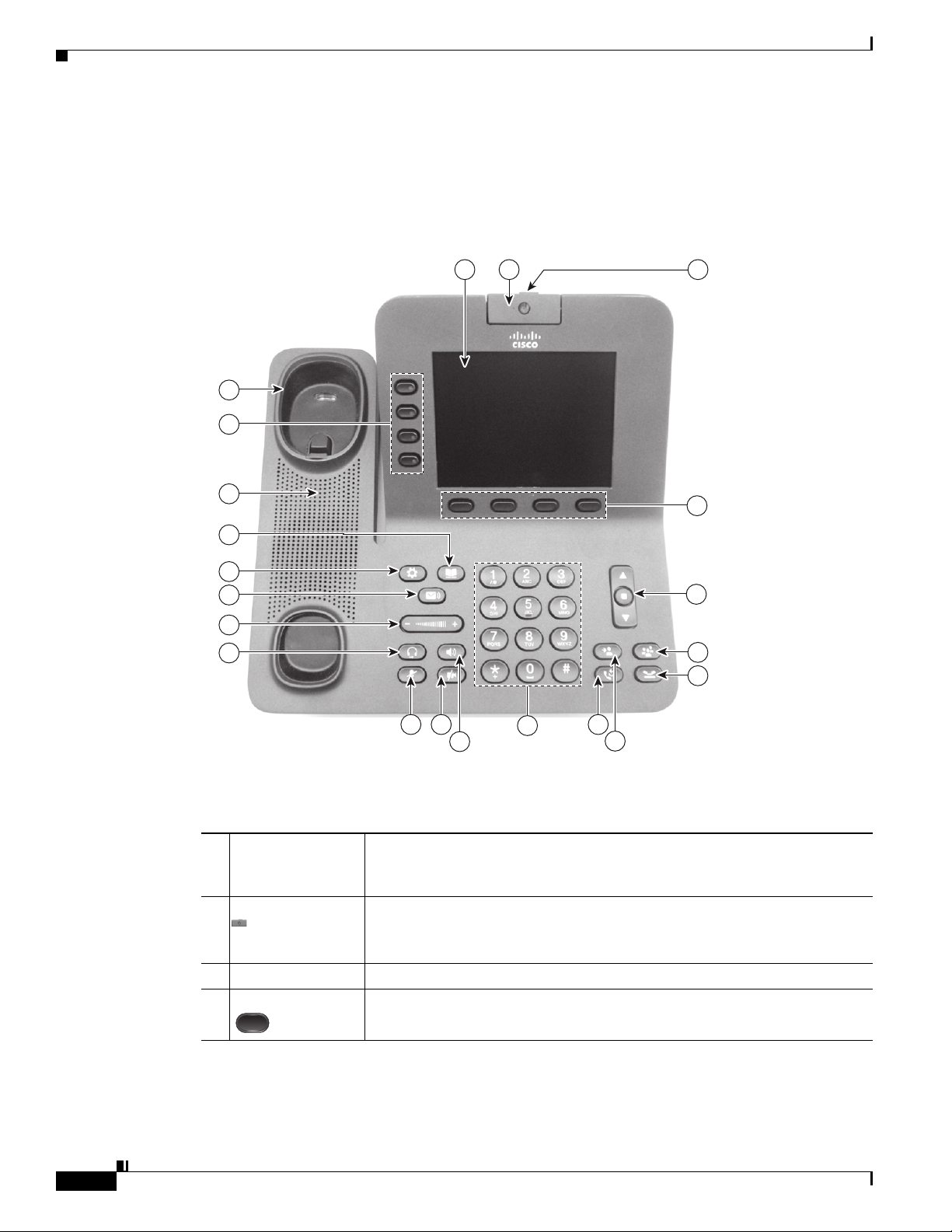
Figure 1-1 shows the main components of the Cisco Unified IP Phone 8941 and 8945.
Figure 1-1 Cisco Unified IP Phone 8941 and 8945
1 2 3
21
20
Chapter
19
18
17
16
15
14
13 12 9
11
10
8
4
5
6
7
236961
Table 1-1 describes the buttons on the Cisco Unified IP Phone 8941 and 8945.
Table 1-1 Features on the Cisco Unified IP Phone 8941 and 8945
1 Phone screen Shows information about your phone, including directory number, call
information (for example caller ID, icons for an active call or call on hold)
and available softkeys.
2 Video Camera Connects to your Cisco Unified IP Phone and allows you to make a
point-to-point video call with another Cisco Unified IP Phone.
1-2
Lens Cover button Integrated lens cover protects the camera lens.
3
4 Softkey buttons Allows you to access the softkey options (for the selected call or menu item)
displayed on your phone screen.
Cisco Unified IP Phone 8941 and 8945 Administration Guide for Cisco Unified Communications Manager 8.5 (SCCP and SIP)
OL-20851-01
Page 15

Chapter
Understanding the Cisco Unified IP Phones 8941 and 8945
Table 1-1 Features on the Cisco Unified IP Phone 8941 and 8945
5 Navigation pad
and Select button
The two-way Navigation pad allows you to scroll through menus, highlight
items, and move within a text input field.
The Select button (center of the Navigation pad) allows you to select a
highlighted item.
The Select button is lit (white) when the phone is in power-save mode.
6 Conference button Creates a conference call.
7 Hold button Places a connected call on hold.
8 Transfer button Transfers a call.
9 Redial button Redials a call.
10 Keypad Allows you to dial phone numbers, enter letters, and choose menu items (by
entering the item number).
11 Speakerphone
button
Selects the speakerphone as the default audio path and initiates a new call,
picks up an incoming call, or ends a call. During a call, the button is lit green.
The speakerphone audio path does not change until a new default audio path
is selected (for example, by picking up the handset).
If external speakers are connected, the Speakerphone button selects them as
the default audio path.
12 Video Mute button
Mutes the video from the phone screen during a video call. When Video
Mute is on, the Video Mute button is lit red.
13 Mute button Toggles the microphone on or off during a call. When the microphone is
muted, the button is lit red.
14 Headset button Selects the headset as the default audio path and initiates a new call, picks up
an incoming call, or ends a call. During a call, the button is lit green.
A headset icon in the phone screen header line indicates the headset is the
default audio path. This audio path does not change until a new default audio
path is selected (for example, by picking up the handset).
15 Volume button Controls the handset, headset, and speakerphone volume (off hook) and the
ringer volume (on hook).
Silences the ringer on the phone if an incoming call is ringing.
16 Messages button Auto-dials your voicemail system (varies by system).
OL-20851-01
Cisco Unified IP Phone 8941 and 8945 Administration Guide for Cisco Unified Communications Manager 8.5 (SCCP and SIP)
1-3
Page 16

What Networking Protocols are Used?
Table 1-1 Features on the Cisco Unified IP Phone 8941 and 8945
Chapter
17 Applications
button
18 Contacts button Opens the Contacts menu. Depending on how your system administrator sets
19 Phone Speaker Speaker for the phone.
20 Programmable
feature buttons
(also called Line
buttons)
21 Handset rest To rest the phone handset.
Opens the Applications menu. Depending on how your system administrator
sets up the phone, use it to access applications such as call history,
preferences, and phone information.
up the phone, use it to access personal directory, corporate directory, or call
history.
Each corresponds with a phone line, speed dial, and calling feature.
Pressing a button for a phone line displays the active calls for that line.
Color LEDs indicate the line state:
• Amber —Ringing call on this line
• Green —Active or held call on this line
• Red —Shared line in-use remotely
What Networking Protocols are Used?
Cisco Unified IP Phones support several industry-standard and Cisco networking protocols required for
voice communication. Table 1-2 provides an overview of the networking protocols that the Cisco Unified
IP Phones 8941 and 8945 support.
Table 1-2 Supported Networking Protocols on the Cisco Unified IP Phone
Networking Protocol Purpose Usage Notes
Bootstrap Protocol
(BootP)
Cisco Audio Session
Tunneling (CAST)
BootP enables a network device such as
the Cisco Unified IP Phone to discover
certain startup information, such as its IP
address.
The CAST protocol allows IP phones and
associated applications behind the phone
to discover and communicate with the
remote endpoints without requiring
changes to the traditional signaling
components like Cisco Unified
Communications Manager (Cisco Unified
CM) and gateways. The Cast protocol
allows separate hardware devices to
synchronize related media and it allows
PC applications to augment non Video
capable phones to become video enabled
by using the PC as the video resource.
—
—
1-4
Cisco Unified IP Phone 8941 and 8945 Administration Guide for Cisco Unified Communications Manager 8.5 (SCCP and SIP)
OL-20851-01
Page 17

Chapter
What Networking Protocols are Used?
Table 1-2 Supported Networking Protocols on the Cisco Unified IP Phone (continued)
Networking Protocol Purpose Usage Notes
Cisco Discovery Protocol
(CDP)
CDP is a device-discovery protocol that
runs on all Cisco-manufactured
equipment.
Using CDP, a device can advertise its
existence to other devices and receive
information about other devices in the
network.
Dynamic Host
Configuration Protocol
(DHCP)
DHCP dynamically allocates and assigns
an IP address to network devices.
DHCP enables you to connect an IP phone
into the network and have the phone
become operational without your needing
to manually assign an IP address or to
configure additional network parameters.
Hypertext Transfer
Protocol (HTTP)
HTTP is the standard way of transferring
information and moving documents across
the Internet and the web.
IEEE 802.1X The IEEE 802.1X standard defines a
client-server-based access control and
authentication protocol that restricts
unauthorized clients from connecting to a
LAN through publicly accessible ports.
Until the client is authenticated, 802.1X
access control allows only Extensible
Authentication Protocol over LAN
(EAPOL) traffic through the port to which
the client is connected. After
authentication is successful, normal traffic
can pass through the port.
Internet Protocol (IP) IP is a messaging protocol that addresses
and sends packets across the network.
Link Layer Discovery
Protocol (LLDP)
LLDP is a standardized network discovery
protocol (similar to CDP) that is supported
on some Cisco and third-party devices.
The Cisco Unified IP Phone uses CDP to
communicate information such as auxiliary VLAN ID,
per port power management details, and Quality of
Service (QoS) configuration information with the
Cisco Catalyst switch.
DHCP is enabled by default. If disabled, you must
manually configure the IP address, subnet mask,
gateway, and a TFTP server on each phone locally.
Cisco recommends that you use DHCP custom
option 150. With this method, you configure the
TFTP server IP address as the option value. For
additional supported DHCP configurations, go to
the Dynamic Host Configuration Protocol chapter
and the Cisco TFTP chapter in the Cisco Unified
Communications Manager System Guide.
Note If you cannot use option 150, you may try
using DHCP option 66.
Cisco Unified IP Phones use HTTP for the XML
services and for troubleshooting purposes.
The Cisco Unified IP Phone implements the IEEE
802.1X standard by providing support for the
following authentication methods: EAP-FAST,
EAP-TLS, and EAP-MD5.
When 802.1X authentication is enabled on the
phone, you should disable the PC port and voice
VLAN. Refer to the “Supporting 802.1X
Authentication on Cisco Unified IP Phones” section
on page 1-16 for additional information.
To communicate using IP, network devices must
have an assigned IP address, subnet, and gateway.
IP addresses, subnets, and gateways identifications
are automatically assigned if you are using the
Cisco Unified IP Phone with Dynamic Host
Configuration Protocol (DHCP). If you are not
using DHCP, you must manually assign these
properties to each phone locally.
The Cisco Unified IP Phone supports LLDP on the
PC port.
OL-20851-01
Cisco Unified IP Phone 8941 and 8945 Administration Guide for Cisco Unified Communications Manager 8.5 (SCCP and SIP)
1-5
Page 18

What Networking Protocols are Used?
Table 1-2 Supported Networking Protocols on the Cisco Unified IP Phone (continued)
Networking Protocol Purpose Usage Notes
Link Layer Discovery
Protocol-Media Endpoint
Devices (LLDP-MED)
Real-Time Transport
Protocol (RTP)
Real-Time Control
Protocol (RTCP)
Session Initiation Protocol
(SIP)
Skinny Client Control
Protocol (SCCP)
Secure Real-Time
Transfer protocol (SRTP)
Transmission Control
Protocol (TCP)
LLDP-MED is an extension of the LLDP
standard developed for voice products.
RTP is a standard protocol for transporting
real-time data, such as interactive voice
and video, over data networks.
RTCP works in conjunction with RTP to
provide QoS data (such as jitter, latency,
and round trip delay) on RTP streams.
SIP is the Internet Engineering Task Force
(IETF) standard for multimedia
conferencing over IP. SIP is an
ASCII-based application-layer control
protocol (defined in RFC 3261) that can be
used to establish, maintain, and terminate
calls between two or more endpoints.
SCCP includes a messaging set that allows
communications between call control
servers and endpoint clients such as
IP Phones. SCCP is proprietary to Cisco
Systems.
SRTP is an extension of the Real-Time
Protocol (RTP) Audio/Video Profile and
ensures the integrity of RTP and
Real-Time Control Protocol (RTCP)
packets providing authentication,
integrity, and encryption of media packets
between two endpoints.
TCP is a connection-oriented transport
protocol.
The Cisco Unified IP Phone supports LLDP-MED
on the SW port to communicate information such as:
• Voice VLAN configuration
• Device discovery
• Power management
• Inventory management
For more information about LLDP-MED support,
see the LLDP-MED and Cisco Discovery Protocol
white paper:
http://www.cisco.com/en/US/tech/tk652/tk701/tech
nologies_white_paper0900aecd804cd46d.shtml
Cisco Unified IP Phones use the RTP protocol to
send and receive real-time voice traffic from other
phones and gateways.
RTCP is disabled by default, but you can enable it
on a per phone basis by using Cisco Unified CM.
Like other VoIP protocols, SIP is designed to
address the functions of signaling and session
management within a packet telephony network.
Signaling allows call information to be carried
across network boundaries. Session management
provides the ability to control the attributes of an
end-to-end call.
You can configure the Cisco Unified IP Phone to use
either SIP or Skinny Client Control Protocol
(SCCP). Cisco Unified IP Phones do not support the
SIP protocol when the phones are operating in IPv6
address mode.
Cisco Unified IP Phone 8941 and 8945 use SCCP,
version 20 for call control.
Cisco Unified IP Phones use SRTP for media
encryption.
Cisco Unified IP Phones use TCP to connect to
Cisco Unified CM and to access XML services.
Chapter
1-6
Cisco Unified IP Phone 8941 and 8945 Administration Guide for Cisco Unified Communications Manager 8.5 (SCCP and SIP)
OL-20851-01
Page 19

Chapter
What Features are Supported on the Cisco Unified IP Phone 8941 and 8945?
Table 1-2 Supported Networking Protocols on the Cisco Unified IP Phone (continued)
Networking Protocol Purpose Usage Notes
Transport Layer Security
(TLS)
Trivial File Transfer
Protocol (TFTP)
User Datagram Protocol
(UDP)
TLS is a standard protocol for securing
and authenticating communications.
TFTP allows you to transfer files over the
network.
On the Cisco Unified IP Phone, TFTP
enables you to obtain a configuration file
specific to the phone type.
UDP is a connectionless messaging
protocol for delivery of data packets.
When security is implemented, Cisco
Unified IP Phones use the TLS protocol when
securely registering with Cisco Unified CM.
For more information, refer to the Cisco Unified
Communications Manager Security Guide.
TFTP requires a TFTP server in your network,
which can be automatically identified from the
DHCP server. If you want a phone to use a TFTP
server other than the one specified by the DHCP
server, you must manually assign the IP address of
the TFTP server by using the Network Setup menu
on the phone.
For more information, refer to the Cisco TFTP
chapter in the Cisco Unified Communications
Manager System Guide.
Cisco Unified IP Phones transmit and receive RTP
streams, which utilize UDP.
Related Topics
• Understanding Interactions with Other Cisco Unified IP Telephony Products, page 2-1
• Understanding the Phone Startup Process, page 2-6
• Network Setup Menu, page 4-4
What Features are Supported on the Cisco Unified
Phone 8941 and 8945?
IP
Cisco Unified IP Phones function much like a digital business phone, allowing you to place and receive
phone calls. In addition to traditional telephony features, the Cisco Unified IP Phone includes features
that enable you to administer and monitor the phone as a network device.
This section includes the following topics:
• Feature Overview, page 1-8
• Configuring Telephony Features, page 1-8
• Configuring Network Parameters Using the Cisco Unified IP Phone, page 1-9
• Providing Users with Feature Information, page 1-9
OL-20851-01
Cisco Unified IP Phone 8941 and 8945 Administration Guide for Cisco Unified Communications Manager 8.5 (SCCP and SIP)
1-7
Page 20

What Features are Supported on the Cisco Unified IP Phone 8941 and 8945?
Feature Overview
Cisco Unified IP Phones provide traditional telephony functionality, such as call forwarding and
transferring, redialing, speed dialing, conference calling, and voice messaging system access.
Cisco Unified IP phones also provide a variety of other features. For an overview of the telephony
features that the Cisco Unified IP Phone supports and for tips on configuring them, see the “Telephony
Features Available for the Cisco Unified IP Phone” section on page 5-1.
As with other network devices, you must configure Cisco Unified IP Phones to prepare them to access
Cisco Unified CM and the rest of the IP network. By using DHCP, you have fewer settings to configure
on a phone, but if your network requires it, you can manually configure an IP address, TFTP server,
subnet information, and so on. For instructions on configuring the network settings on the Cisco Unified
IP Phones, see Chapter 4, “Configuring Settings on the Cisco Unified IP Phone.”
Cisco Unified IP Phones can interact with other services and devices on your IP network to provide
enhanced functionality. For example, you can integrate Cisco Unified CM with the corporate
Lightweight Directory Access Protocol 3 (LDAP3) standard directory to enable users to search for
co-worker contact information directly from their IP phones. You can also use XML to enable users to
access information such as weather, stocks, quote of the day, and other web-based information. For
information about configuring such services, see the “Join and Direct Transfer Policy” section on
page 5-16 and the “Setting Up Services” section on page 5-21.
Finally, because the Cisco Unified IP Phone is a network device, you can obtain detailed status
information from it directly. This information can assist you with troubleshooting any problems users
might encounter when using their IP phones. See Chapter 7, “Viewing Model Information, Status, and
Statistics on the Cisco Unified IP Phone,” for more information.
Chapter
Related Topics
• Configuring Settings on the Cisco Unified IP Phone, page 4-1
• Configuring Features, Templates, Services, and Users, page 5-1
• Troubleshooting and Maintenance, page 9-1
Configuring Telephony Features
You can modify additional settings for the Cisco Unified IP Phone from Cisco Unified CM
Administration. Use Cisco Unified CM Administration to set up phone registration criteria and calling
search spaces, to configure corporate directories and services, and to modify phone button templates,
among other tasks. See the “Telephony Features Available for the Cisco Unified IP Phone” section on
page 5-1 and the Cisco Unified CM documentation for additional information.
For more information about Cisco Unified CM Administration, refer to Cisco Unified CM
documentation, including Cisco Unified Communications Manager Administration Guide. You can also
use the context-sensitive help available within the application for guidance.
You can access Cisco Unified CM documentation at this location:
http://www.cisco.com/en/US/products/sw/voicesw/ps556/tsd_products_support_series_home.html
You can access Cisco Unified Communications Manager Business Edition documentation at
this location:
http://www.cisco.com/en/US/products/ps7273/tsd_products_support_series_home.html
1-8
Related Topic
• Telephony Features Available for the Cisco Unified IP Phone, page 5-1
Cisco Unified IP Phone 8941 and 8945 Administration Guide for Cisco Unified Communications Manager 8.5 (SCCP and SIP)
OL-20851-01
Page 21

Chapter
Understanding Security Features for Cisco Unified IP Phones
Configuring Network Parameters Using the Cisco Unified IP Phone
You can configure parameters such as DHCP, TFTP, and IP settings on the phone itself. You can also
obtain statistics about a current call or firmware versions on the phone.
For more information about configuring features and viewing statistics from the phone, see Chapter 4,
“Configuring Settings on the Cisco Unified IP Phone” and see Chapter 7, “Viewing Model Information,
Status, and Statistics on the Cisco Unified IP Phone.”
Providing Users with Feature Information
If you are a system administrator, you are likely the primary source of information for Cisco Unified IP
Phone users in your network or company. To ensure that you distribute the most current feature and
procedural information, familiarize yourself with Cisco Unified IP Phone documentation on the
Cisco Unified IP Phone web site:
http://www.cisco.com/en/US/products/ps10451/tsd_products_support_series_home.html
From this site, you can view various user documentation.
In addition to providing documentation, it is important to inform users of available Cisco Unified IP
Phone features—including those specific to your company or network—and of how to access and
customize those features, if appropriate.
For a summary of some of the key information that phone users need their system administrators to
provide, see Appendix A, “Providing Information to Users Via a Website.”
Understanding Security Features for Cisco Unified IP Phones
Implementing security in the Cisco Unified CM system prevents identity theft of the phone and
Cisco Unified CM server, prevents data tampering, and prevents call signaling and media stream
tampering.
To alleviate these threats, the Cisco IP telephony network establishes and maintains secure
communication streams between a phone and the server, digitally signs files before they are transferred
to a phone, and encrypts media streams and call signaling between Cisco Unified IP phones.
The Cisco Unified IP Phone 8941 and 8945 use the Phone security profile, which defines whether the
device is nonsecure or encrypted. For information on applying the security profile to the phone, refer to
the Cisco Unified Communications Manager Security Guide.
If you configure security-related settings in Cisco Unified CM Administration, the phone configuration
file will contain sensitive information. To ensure the privacy of a configuration file, you must configure
it for encryption. For detailed information, refer to the “Configuring Encrypted Phone Configuration
Files” chapter in Cisco Unified Communications Manager Security Guide.
Table 1-3 shows where you can find additional information about security in this and other documents.
OL-20851-01
Cisco Unified IP Phone 8941 and 8945 Administration Guide for Cisco Unified Communications Manager 8.5 (SCCP and SIP)
1-9
Page 22

Chapter
Understanding Security Features for Cisco Unified IP Phones
Table 1-3 Cisco Unified IP Phone and Cisco Unified CM Security Topics
Topic Reference
Detailed explanation of security, including set
up, configuration, and troubleshooting
information for Cisco Unified CM and Cisco
Unified IP Phones
Security features supported on the Cisco Unified
IP Phone
Restrictions regarding security features See the “Security Restrictions” section on page 1-17
Viewing a security profile name See the “Understanding Security Profiles” section on page 1-13
Identifying phone calls for which security is
implemented
TLS connection
Security and the phone startup process See the “Understanding the Phone Startup Process” section on page 2-6
Security and phone configuration files See the “Adding Phones to the Cisco Unified CM Database” section on
Changing the TFTP Server 1 or TFTP Server 2
option on the phone when security is
implemented
Items on the Security Configuration menu that
you access from the Device Configuration menu
on the phone
Items on the Security Configuration menu that
you access from the Settings menu on the phone
Applying a password to the phone so that no
changes can be made to the administrative
options
Disabling access to a phone’s web pages See the “Disabling and Enabling Web Page Access” section on page 8-3
Troubleshooting
Deleting the CTL file from the phone See the “Resetting or Restoring the Cisco Unified IP Phone” section on
Refer to the Cisco Unified Communications Manager Security Guide.
See the “Overview of Supported Security Features” section on page 1-11
See the “Identifying Encrypted Phone Calls” section on page 1-13
• See the “What Networking Protocols are Used?” section on page 1-4
• See the “Adding Phones to the Cisco Unified CM Database” section on
page 2-8
page 2-8
See Table 4- 2 , in the “Network Setup Menu” section on page 4-4
See the “Security Configuration Menu” section on page 4-8
See the “Security Configuration Menu” section on page 4-8
See the “Unlocking and Locking Options” section on page 4-3
• See the “Troubleshooting Cisco Unified IP Phone Security” section on
page 9-8
• Refer to the Troubleshooting Guide for Cisco Unified
Communications Manager
page 9-12
1-10
Cisco Unified IP Phone 8941 and 8945 Administration Guide for Cisco Unified Communications Manager 8.5 (SCCP and SIP)
OL-20851-01
Page 23

Chapter
Understanding Security Features for Cisco Unified IP Phones
Table 1-3 Cisco Unified IP Phone and Cisco Unified CM Security Topics (continued)
Topic Reference
Resetting or restoring the phone See the “Resetting or Restoring the Cisco Unified IP Phone” section on
page 9-12
802.1X Authentication for Cisco Unified IP
Phones
All Cisco Unified IP Phones that support Cisco Unified CM use a security profile, which defines whether
the phone is nonsecure or secure.
For information about configuring the security profile and applying the profile to the phone, refer to
Cisco Unified Communications Manager Security Guide.
See these sections:
• “Supporting 802.1X Authentication on Cisco Unified IP Phones”
section on page 1-16
• “Security Configuration Menu” section on page 4-8
• “Status Menu” section on page 7-2
• “Troubleshooting Cisco Unified IP Phone Security” section on
page 9-8
Overview of Supported Security Features
Table 1-4 provides an overview of the security features that the Cisco Unified IP Phone 8941 and 8945
support. For more information about these features and about Cisco Unified CM and
Cisco Unified IP Phone security, refer to Cisco Unified Communications Manager Security Guide.
For information about current security settings on a phone, choose Applications > Administrator
Settings > Security Setup. For more information, see the “Security Configuration Menu” section on
page 4-8.
Note Most security features are available only if a certificate trust list (CTL) is installed on the phone. For
more information about the CTL, refer to “Configuring the Cisco CTL Client” chapter in Cisco Unified
Communications Manager Security Guide.
Table 1-4 Overview of Security Features
Feature Description
Image authentication Signed binary files (with the extension .sgn) prevent tampering with the
firmware image before it is loaded on a phone. Tampering with the image causes
a phone to fail the authentication process and reject the new image.
Customer-site certificate installation Each Cisco Unified IP Phone requires a unique certificate for device
authentication. Phones include a manufacturing installed certificate (MIC), but
for additional security, you can specify in Cisco Unified CM Administration that
a certificate be installed by using the Certificate Authority Proxy Function
(CAPF). Alternatively, you can install a Locally Significant Certificate (LSC)
from the Security Configuration menu on the phone. See the “Configuring
Security on the Cisco Unified IP Phone” section on page 3-11 for more
information.
OL-20851-01
Cisco Unified IP Phone 8941 and 8945 Administration Guide for Cisco Unified Communications Manager 8.5 (SCCP and SIP)
1-11
Page 24

Chapter
Understanding Security Features for Cisco Unified IP Phones
Table 1-4 Overview of Security Features (continued)
Feature Description
Device authentication Occurs between the Cisco Unified CM server and the phone when each entity
accepts the certificate of the other entity. Determines whether a secure
connection between the phone and a Cisco Unified CM should occur; and, if
necessary, creates a secure signaling path between the entities by using TLS
protocol. Cisco Unified CM will not register phones unless they can be
authenticated by the Cisco Unified CM.
File authentication Validates digitally signed files that the phone downloads. The phone validates
the signature to make sure that file tampering did not occur after the file creation.
Files that fail authentication are not written to Flash memory on the phone. The
phone rejects such files without further processing.
Signaling Authentication Uses the TLS protocol to validate that no tampering has occurred to signaling
packets during transmission.
Manufacturing installed certificate Each Cisco Unified IP Phone contains a unique manufacturing installed
certificate (MIC), which is used for device authentication. The MIC is a
permanent unique proof of identity for the phone, and allows Cisco Unified CM
to authenticate the phone.
Secure SRST reference After you configure a SRST reference for security and then reset the dependent
devices in Cisco Unified CM Administration, the TFTP server adds the SRST
certificate to the phone cnf.xml file and sends the file to the phone. A secure
phone then uses a TLS connection to interact with the SRST-enabled router.
Media encryption Uses SRTP to ensure that the media streams between supported devices proves
secure and that only the intended device receives and reads the data. Includes
creating a media master key pair for the devices, delivering the keys to the
devices, and securing the delivery of the keys while the keys are in transport.
Signaling encryption Ensures that all SCCP signaling messages that are sent between the device and
the Cisco Unified CM server are encrypted.
CAPF (Certificate Authority Proxy
Function)
Security profiles Defines whether the phone is nonsecure or encrypted. See the “Understanding
Encrypted configuration files Lets you ensure the privacy of phone configuration files.
Optional disabling of the web server
functionality for a phone
Implements parts of the certificate generation procedure that are too
processing-intensive for the phone, and interacts with the phone for key
generation and certificate installation. The CAPF can be configured to request
certificates from customer-specified certificate authorities on behalf of the
phone, or it can be configured to generate certificates locally.
Security Profiles” section on page 1-13 for more information.
You can prevent access to a phone’s web page, which displays a variety of
operational statistics for the phone. See the “Disabling and Enabling Web Page
Access” section on page 8-3.
1-12
Cisco Unified IP Phone 8941 and 8945 Administration Guide for Cisco Unified Communications Manager 8.5 (SCCP and SIP)
OL-20851-01
Page 25

Chapter
Understanding Security Features for Cisco Unified IP Phones
Table 1-4 Overview of Security Features (continued)
Feature Description
Phone hardening Additional security options, which you control from Cisco Unified CM
Administration:
• Disabling PC port
• Disabling PC Voice VLAN access
• Disabling access to web pages for a phone
Note You can view current settings for the PC Port Disabled, GARP Enabled,
and Voice VLAN enabled options by looking at the phone’s Security
Configuration menu. For more information, see the “Security
Configuration Menu” section on page 4-8.
802.1X Authentication The Cisco Unified IP Phone can use 802.1X authentication to request and gain
access to the network. See the “Supporting 802.1X Authentication on Cisco
Unified IP Phones” section on page 1-16 for more information.
Related Topics
• Understanding Security Profiles, page 1-13
• Identifying Encrypted Phone Calls, page 1-13
• Security Restrictions, page 1-17
Understanding Security Profiles
All Cisco Unified IP Phones that support Cisco Unified CM use a security profile, which defines whether
the phone is nonsecure or encrypted. For information about configuring the security profile and applying
the profile to the phone, refer to Cisco Unified Communications Manager Security Guide.
To view the security mode that is set for the phone, look at the Security Mode setting in the Security
Configuration menu. For more information, see the “Security Configuration Menu” section on page 4-8.
Related Topics
• Identifying Encrypted Phone Calls, page 1-13
• Security Restrictions, page 1-17
Identifying Encrypted Phone Calls
When security is implemented for a phone, you can identify encrypted phone audio calls by icons on the
screen on the phone. You can also determine if the connected phone is secure and protected if a security
tone plays at the beginning of the call.
In a secure call, all call signaling and media streams are encrypted. An encrypted call offers a high level
of security, providing integrity and privacy to the call. When a call in progress is being encrypted, the
call progress icon to the right of the call duration timer in the phone LCD screen changes to the lock
icon: .
If the call is routed through non-IP call legs, for example, PSTN, the call may be nonsecure even though
it is encrypted within the IP network and has a lock icon associated with it.
OL-20851-01
Cisco Unified IP Phone 8941 and 8945 Administration Guide for Cisco Unified Communications Manager 8.5 (SCCP and SIP)
1-13
Page 26

Understanding Security Features for Cisco Unified IP Phones
In a secure call, a security tone plays at the beginning of a call to indicate that the other connected phone
is also receiving and transmitting encrypted audio. For video calls, the user may first hear secure
indication tone for the audio portion of the call and then nonsecure indication tone for overall nonsecure
media. If your call is connected to a non-protected phone, the security tone does not play.
Note Secured calling is supported for connections between two phones only. Some features, such as
conference calling, shared lines, and Cisco Extension Mobilityare not available when secured calling is
configured.
Related Topic
• Understanding Security Profiles, page 1-13
• Understanding Security Features for Cisco Unified IP Phones, page 1-9
• Security Restrictions, page 1-17
Establishing and Identifying Secure Audio Conference Calls
You can initiate a secure conference audio call and monitor the security level of participants. A secure
conference call is established using this process:
Chapter
1. A user initiates the conference from a secure phone.
2. Cisco Unified CM assigns a secure conference bridge to the call.
3. As participants are added, Cisco Unified CM verifies the security mode of each phone and maintains
the secure level for the conference.
4. The phone displays the security level of the conference call. A secure conference displays the
to the right of “Conference” on the phone screen.
Note There are interactions, restrictions, and limitations that affect the security level of the audio conference
call depending on the security mode of the participant’s phones and the availability of secure conference
bridges. See Tabl e 1-5 and Tab l e 1-6 for information about these interactions.
Establishing and Identifying Protected Calls
A protected call is established when your phone, and the phone on the other end, is configured for
protected calling. The other phone can be in the same Cisco IP network, or on a network outside the IP
network. Protected calls can only be made between two phones. Conference calls and other multiple-line
calls are not supported.
A protected call is established using this process:
1. A user initiates the call from a protected phone (protected security mode).
2. The phone displays the icon (encrypted) on the phone screen. This icon indicates that the phone
is configured for secure (encrypted) calls, but this does not mean that the other connected phone is
also protected.
1-14
3. A security tone plays if the call is connected to another protected phone, indicating that both ends
of the conversation are encrypted and protected. For video calls, the user may first hear secure
indication tone for the audio portion of the call and then nonsecure indication tone for overall
nonsecure media. If the call is connected to a non-protected phone, then the secure tone is not
played.
Cisco Unified IP Phone 8941 and 8945 Administration Guide for Cisco Unified Communications Manager 8.5 (SCCP and SIP)
OL-20851-01
Page 27

Chapter
Note Protected calling is supported for conversations between two phones. Some features, such as conference
calling, shared lines, Cisco Extension Mobility, and Join Across Lines are not available when protected
calling is configured.
Call Security Interactions and Restrictions
Cisco Unified CM checks the phone security status when audio conferences are established and changes
the security indication for the conference or blocks the completion of the call to maintain integrity and
also security in the system.
using Barge.
Table 1-5 Call Security Interactions When Using Barge
Initiator’s Phone
Security Level Feature Used Call Security Level Results of Action
Non-secure cBarge Encrypted call Call barged and identified as nonsecure call
Secure cBarge Secure call Call barged and identified as Secure call
Table 1-5 provides information about changes to call security levels when
Understanding Security Features for Cisco Unified IP Phones
Table 1-6 provides information about changes to conference security levels depending on the initiator’s
phone security level, the security levels of participants, and the availability of secure conference bridges.
Table 1-6 Security Restrictions with Conference Calls
Initiator’s Phone
Security Level Feature Used Security Level of Participants Results of Action
Non-secure Conference Encrypted Nonsecure conference bridge
Nonsecure conference
Secure Conference At least one member is
non-secure
Secure conference bridge
Nonsecure conference
Secure Conference All participants are encrypted Secure conference bridge
Secure encrypted level
conference
Secure Join Encrypted Secure conference bridge
Conference remains secure
Non-secure cBarge All participants are encrypted Secure conference bridge
Conference changes to
non-secure
Non-secure MeetMe Minimum security level is
encrypted
Only non-secure conference
bridge is available and used
Non-secure conference
Secure MeetMe Minimum security level is
nonsecure
Only secure conference bridge
available and used
Conference accepts all calls
OL-20851-01
Cisco Unified IP Phone 8941 and 8945 Administration Guide for Cisco Unified Communications Manager 8.5 (SCCP and SIP)
1-15
Page 28

Understanding Security Features for Cisco Unified IP Phones
Supporting 802.1X Authentication on Cisco Unified IP Phones
These sections provide information about 802.1X support on the Cisco Unified IP Phones:
• Overview, page 1-16
• Required Network Components, page 1-16
• Best Practices—Requirements and Recommendations, page 1-16
Overview
Cisco Unified IP phones and Cisco Catalyst switches have traditionally used Cisco Discovery Protocol
(CDP) to identify each other and determine parameters such as VLAN allocation and inline power
requirements. However, CDP is not used to identify any locally attached PCs; therefore, Cisco Unified
IP Phones provide an EAPOL pass-through mechanism, whereby a PC locally attached to the IP phone,
may pass through EAPOL messages to the 802.1X authenticator in the LAN switch. This prevents the
IP phone from having to act as the authenticator, yet allows the LAN switch to authenticate a data end
point prior to accessing the network.
In conjunction with the EAPOL pass-through mechanism, Cisco Unified IP Phones provide a proxy
EAPOL-Logoff mechanism. In the event that the locally attached PC is disconnected from the IP phone,
the LAN switch would not see the physical link fail, because the link between the LAN switch and the
IP phone is maintained. To avoid compromising network integrity, the IP phone sends an EAPOL-Logoff
message to the switch, on behalf of the downstream PC, which triggers the LAN switch to clear the
authentication entry for the downstream PC.
The Cisco Unified IP phones also contain an 802.1X supplicant, in addition to the EAPOL pass-through
mechanism. This supplicant allows network administrators to control the connectivity of IP phones to
the LAN switch ports. The current release of the phone 802.1X supplicant uses the EAP-FAST,
EAP-TLS, and EAP-MD5 options for network authentication.
Chapter
Required Network Components
Support for 802.1X authentication on Cisco Unified IP Phones requires several components, including:
• Cisco Unified IP Phone—The phone acts as the 802.1X supplicant, which initiates the request to
access the network.
• Cisco Secure Access Control Server (ACS) (or other third-party authentication server)—The
authentication server and the phone must both be configured with a shared secret that is used to
authenticate the phone.
• Cisco Catalyst Switch (or other third-party switch)—The switch must support 802.1X, so it can act
as the authenticator and pass the messages between the phone and the authentication server. When
the exchange is completed, the switch then grants or denies the phone access to the network.
Best Practices—Requirements and Recommendations
• Enable 802.1X Authentication—If you want to use the 802.1X standard to authenticate Cisco
Unified IP Phones, be sure that you have properly configured the other components before enabling
it on the phone. See the
information.
“802.1X Authentication and Status” section on page 4-8 for more
1-16
Cisco Unified IP Phone 8941 and 8945 Administration Guide for Cisco Unified Communications Manager 8.5 (SCCP and SIP)
OL-20851-01
Page 29

Chapter
Overview of Configuring and Installing Cisco Unified IP Phones
• Configure PC Port—The 802.1X standard does not take into account the use of VLANs and thus
recommends that only a single device should be authenticated to a specific switch port. However,
some switches (including Cisco Catalyst switches) support multi-domain authentication. The switch
configuration determines whether you can connect a PC to the phone’s PC port.
–
Enabled—If you are using a switch that supports multi-domain authentication, you can enable
the PC port and connect a PC to it. In this case, Cisco Unified IP Phones support proxy
EAPOL-Logoff to monitor the authentication exchanges between the switch and the attached
PC. For more information about IEEE 802.1X support on the Cisco Catalyst switches, refer to
the Cisco Catalyst switch configuration guides at:
http://www.cisco.com/en/US/products/hw/switches/ps708/tsd_products_support_series_home.
html
–
Disabled—If the switch does not support multiple 802.1X-compliant devices on the same port,
you should disable the PC Port when 802.1X authentication is enabled. See the
Configuration Menu” section on page 4-8 for more information. If you do not disable this port
and subsequently attempt to attach a PC to it, the switch will deny network access to both the
phone and the PC.
• Configure Voice VLAN—Because the 802.1X standard does not account for VLANs, you should
configure this setting based on the switch support.
“Security
–
Enabled—If you are using a switch that supports multi-domain authentication, you can continue
to use the voice VLAN.
–
Disabled—If the switch does not support multi-domain authentication, disable the Voice VLAN
and consider assigning the port to the native VLAN. See the
section on page 4-8 for more information.
• Enter MD5 Shared Secret—If you disable 802.1X authentication or perform a factory reset on the
phone, the previously configured MD5 shared secret is deleted. See the
Status” section on page 4-8 for more information.
“Security Configuration Menu”
“802.1X Authentication and
Security Restrictions
A user cannot barge into an encrypted call if the phone that is used to barge is not configured for
encryption. When barge fails in this case, a reorder tone (fast busy tone) plays on the phone on which
the user initiated the barge.
If the initiator phone is configured for encryption, the barge initiator can barge into a nonsecure call from
the encrypted phone. After the barge occurs, Cisco Unified CM classifies the call as nonsecure.
If the initiator phone is configured for encryption, the barge initiator can barge into an encrypted call,
and the phone indicates that the call is encrypted.
Overview of Configuring and Installing Cisco Unified IP Phones
OL-20851-01
When deploying a new IP telephony system, system administrators and network administrators must
complete several initial configuration tasks to prepare the network for IP telephony service. For
information and a checklist for setting up and configuring a Cisco IP telephony network, go to the
System Configuration Overview chapter in Cisco Unified Communications Manager System Guide.
After you have set up the IP telephony system and configured system-wide features in Cisco Unified
CM, you can add IP phones to the system.
Cisco Unified IP Phone 8941 and 8945 Administration Guide for Cisco Unified Communications Manager 8.5 (SCCP and SIP)
1-17
Page 30

Overview of Configuring and Installing Cisco Unified IP Phones
The following topics provide an overview of procedures for adding Cisco Unified IP Phones to
your network:
• Configuring Cisco Unified IP Phones in Cisco Unified CM, page 1-18
• Installing Cisco Unified IP Phones, page 1-22
Configuring Cisco Unified IP Phones in Cisco Unified CM
To add phones to the Cisco Unified CM database, you can use:
• Auto-registration
• Cisco Unified CM Administration
• Bulk Administration Tool (BAT)
• BAT and the Tool for Auto-Registered Phones Support (TAPS)
For more information about these choices, see the “Adding Phones to the Cisco Unified CM Database”
section on page 2-8.
For general information about configuring phones in Cisco Unified CM, refer to the
following documentation:
• Cisco Unified IP Phones, Cisco Unified Communications Manager System Guide
• Cisco Unified IP Phone Configuration, Cisco Unified Communications Manager Administration
Guide
Chapter
• Autoregistration Configuration, Cisco Unified Communications Manager Administration Guide
1-18
Cisco Unified IP Phone 8941 and 8945 Administration Guide for Cisco Unified Communications Manager 8.5 (SCCP and SIP)
OL-20851-01
Page 31

Chapter
Overview of Configuring and Installing Cisco Unified IP Phones
Checklist for Configuring the Cisco Unified IP Phones 8941 and 8945 in Cisco Unified CM
Table 1-7 provides an overview and checklist of configuration tasks for the Cisco Unified IP Phones
8941 and 8945 in Cisco Unified CM Administration. The list presents a suggested order to guide you
through the phone configuration process. Some tasks are optional, depending on your system and user
needs. For detailed procedures and information, refer to the sources in the list.
Table 1-7 Checklist for Configuring the Cisco Unified IP Phones 8941 and 8945 in Cisco Unified CM
Task Purpose For More Information
1. Gather the following information about the phone:
• Phone Model
• MAC address
• Physical location of the phone
• Name or user ID of phone user
• Device pool
• Partition, calling search space, and location
information
• Number of lines and associated directory numbers
(DNs) to assign to the phone
• Cisco Unified CM user to associate with
the phone
For more information, go to the “Cisco Unified
IP Phones chapter in the Cisco Unified Communications
Manager System Guide.
See the “Telephony Features Available for the Cisco
Unified IP Phone” section on page 5-1.
• Phone usage information that affects phone button
template, softkey template, phone features, IP
Phone services, or phone applications
Provides list of configuration requirements for setting
up phones.
Identifies preliminary configuration that you need to
perform before configuring individual phones, such as
phone button templates or softkey templates.
2. Verify that you have sufficient unit licenses for your
phone.
3. Customize phone button templates (if required).
Changes the number of line buttons, speed-dial
buttons, Service URL buttons or adds a Privacy button
to meet user needs.
For more information, go to the License Unit Report
chapter in the Cisco Communications Manager
Administration Guide.
For more information, go to the Phone Button Template
Configuration chapter in the Cisco Communications
Manager Administration Guide.
See the “Modifying Phone Button Templates” section on
page 5-18.
OL-20851-01
Cisco Unified IP Phone 8941 and 8945 Administration Guide for Cisco Unified Communications Manager 8.5 (SCCP and SIP)
1-19
Page 32

Overview of Configuring and Installing Cisco Unified IP Phones
Table 1-7 Checklist for Configuring the Cisco Unified IP Phones 8941 and 8945 in Cisco Unified CM (continued)
Task Purpose For More Information
4. Add and configure the phone by completing the
required fields in the Phone Configuration window.
Required fields are indicated by an asterisk (*) next to
the field name; for example, MAC address and device
pool.
The device with its default settings gets added to the
Cisco Unified CM database.
5. Add and configure directory numbers (lines) on the
phone by completing the required fields in the
Directory Number Configuration window. Required
fields are indicated by an asterisk (*) next to the field
name; for example, directory number and presence
group.
Adds primary and secondary directory numbers and
features associated with directory numbers to the
phone.
6. Customize softkey templates.
Adds, deletes, or changes order of softkey features
that display on the user’s phone to meet feature usage
needs.
7. Configure speed-dial buttons and assign speed-dial
numbers (optional).
Adds speed-dial buttons and numbers.
For more information, go to the Cisco Unified IP Phone
Configuration chapter in the Cisco Communications
Manager Administration Guide.
For information about Product Specific Configuration
fields, refer to “?” Button Help in the Phone
Configuration window.
Note If you want to add both the phone and user to the
Cisco Unified CM database at the same time, go
to the User/Phone Add Configuration chapter in
the Cisco Communications Manager
Administration Guide.
For more information, go to the “Directory Number
Configuration” chapter in the Cisco Unified
Communications Manager Administration Guide.
See the “Telephony Features Available for the Cisco
Unified IP Phone” section on page 5-1.
For more information, see the Cisco Unified
Communications Manager Administration Guide,
Softkey Template Configuration.
For more information, see the Cisco Unified
Communications Manager Administration Guide, Cisco
Unified IP Phone Configuration.
For more information, see the Cisco Unified
Communications Manager Administration Guide, Cisco
Unified IP Phone Configuration.
Chapter
1-20
Users can change speed-dial settings on their phones
by using Cisco Unified CM User Options.
Cisco Unified IP Phone 8941 and 8945 Administration Guide for Cisco Unified Communications Manager 8.5 (SCCP and SIP)
OL-20851-01
Page 33

Chapter
Overview of Configuring and Installing Cisco Unified IP Phones
Table 1-7 Checklist for Configuring the Cisco Unified IP Phones 8941 and 8945 in Cisco Unified CM (continued)
Task Purpose For More Information
8. Add user information by configuring required fields.
Required fields are indicated by an asterisk (*); for
example, User ID and last name.
For more information, see the Cisco Unified
Communications Manager Administration Guide, End
User Configuration.
Note Assign a password (for User Options web
pages) and PIN (for Cisco Extension Mobility
and Personal Directory).
Adds user information to the global directory for
Cisco Unified CM.
9. Associate a user to a user group.
Assigns users a common list of roles and permissions
that apply to all users in a user group. Administrators
can manage user groups, roles, and permissions to
control the level of access (and, therefore, the level of
security) for system users.
Note In order for end users to access Cisco Unified
CM User Options, you must add users to the
standard Cisco CCM End Users group.
10. Associate a user with a phone (optional).
Provides users with control over their phone such a
forwarding calls or adding speed-dial numbers or
services.
Note Some phones, such as those in conference
rooms, do not have an associated user.
Note If your company uses a a Lightweight Directory
Access Protocol (LDAP) directory to store
information on users, you can install and
configure Cisco Unified Communications to use
your existing LDAP directory, refer to
the“Configuring Corporate Directories” section
on page 5-17. Once the Enable Synchronization
from the LDAP Server field is enabled, you will
not be able to add additional users from Cisco
Unified CM Administration.
Note If you want to add both the phone and user to the
Cisco Unified CM database at the same time, see
User/Phone Add Configurations in the Cisco
Unified Communications Manager
Administration Guide.
Refer to the following sections in the Cisco Unified
Communications Manager Administration Guide, End
User Configuration and User Group Configuration.
For more information, see the Cisco Unified
Communications Manager Administration Guide, End
User Configuration.
OL-20851-01
Cisco Unified IP Phone 8941 and 8945 Administration Guide for Cisco Unified Communications Manager 8.5 (SCCP and SIP)
1-21
Page 34

Overview of Configuring and Installing Cisco Unified IP Phones
Installing Cisco Unified IP Phones
After you have added the phones to the Cisco Unified CM database, you can complete the phone
installation. You (or the phone users) can install the phone at the users’s location. The Cisco
Phone Installation Guide, which is provided on the cisco.com web site, provides directions for
connecting the phone handset, cables, and other accessories.
Note Before you install a phone, even if it is new, upgrade the phone to the current firmware image. For
information about upgrading, refer to the Readme file for your phone, which is located at:
http://www.cisco.com/kobayashi/sw-center/index.shtml
After the phone is connected to the network, the phone startup process begins, and the phone registers
with Cisco Unified CM. To finish installing the phone, configure the network settings on the phone
depending on whether you enable or disable DHCP service.
If you used auto-registration, you need to update the specific configuration information for the phone
such as associating the phone with a user, changing the button table, or directory number.
Chapter
Unified IP
Checklist for Installing the Cisco Unified IP Phone 8941 and 8945
Table 1-8 provides an overview and checklist of installation tasks for the Cisco Unified IP Phone 8941
and 8945. The list presents a suggested order to guide you through the phone installation. Some tasks
are optional, depending on your system and user needs. For detailed procedures and information, refer
to the sources in the list.
Table 1-8 Installation Checklist for the Cisco Unified IP Phone 8941 and 8945
Task Purpose For More Information
1. Choose the power source for the phone:
• Power over Ethernet (PoE)
• External power supply
Determines how the phone receives power.
2. Assemble the phone, adjust phone placement, and
connect the network cable.
Locates and installs the phone in the network.
3. Monitor the phone startup process.
Adds primary and secondary directory numbers and
features associated with directory numbers to the
phone.
See the “Providing Power to the Cisco Unified IP Phone”
section on page 2-3.
See the “Installing the Cisco Unified IP Phone” section
on page 3-5.
See the “Footstand” section on page 3-7.
See the “Verifying the Phone Startup Process” section on
page 3-10.
1-22
Verifies that phone is configured properly.
Cisco Unified IP Phone 8941 and 8945 Administration Guide for Cisco Unified Communications Manager 8.5 (SCCP and SIP)
OL-20851-01
Page 35

Chapter
Overview of Configuring and Installing Cisco Unified IP Phones
Table 1-8 Installation Checklist for the Cisco Unified IP Phone 8941 and 8945 (continued)
Task Purpose For More Information
4. If you are configuring the network settings on the
phone, you can set up an IP address for the phone by
either using DHCP or manually entering an IP
address.
Using DHCP—To enable DHCP and allow the DHCP
server to automatically assign an IP address to the
Cisco Unified IP Phone and direct the phone to a
TFTP server, choose Applications > Administrator
Settings > Network Setup > IPv4 Setup and:
• To enable DHCP, set DHCP Enabled to Yes .
DHCP is enabled by default.
• To use an alternate TFTP server, set Alternate
TFTP Server to Yes , and enter the IP address for
the TFTP Server.
Note Consult with the network administrator to
determine whether you need to assign an
alternative TFTP server instead of using the
TFTP server assigned by DHCP.
See the “Configuring Startup Network Settings” section
on page 3-11.
See the “Network Setup Menu” section on page 4-4.
Without DHCP—You must configure the IP address,
subnet mask, TFTP server, and default router locally
on the phone, choose Applications > Administrator
Settings > Network Setup > IPv4 Setup:
To disable DHCP and manually set an IP address:
a. To disable DHCP, set DHCP Enabled to No.
b. Enter the static IP address for phone.
c. Enter the subnet mask.
d. Enter the default router IP addresses.
e. Set Alternate TFTP Server to Ye s, and enter the IP
address for TFTP Server 1.
You must also enter the domain name where the phone
resides by choosing Applications > Administrator
Settings > Network Setup.
5. Set up security on the phone.
Provides protection against data tampering threats and
identity theft of phones.
6. Make calls with the Cisco Unified IP Phone.
Verifies that the phone and features work correctly.
7. Provide information to end users about how to use
their phones and how to configure their phone options.
Ensures that users have adequate information to
successfully use their Cisco Unified IP Phones.
See the “Configuring Security on the Cisco Unified IP
Phone” section on page 3-11.
Refer to Cisco Unified IP Phone 8941 and 8945 User
Guide for Cisco Unified Communications Manager 8.5.
See Appendix A, “Providing Information to Users Via a
Website.”
OL-20851-01
Cisco Unified IP Phone 8941 and 8945 Administration Guide for Cisco Unified Communications Manager 8.5 (SCCP and SIP)
1-23
Page 36

Terminology Differences
Terminology Differences
Table 1-9 highlights some of the important differences in terminology that is used in these documents:
• Cisco Unified IP Phone 8941 and 8945 User Guide for Cisco Unified Communications Manager 8.5
(SCCP and SIP)
• Cisco Unified IP Phone 8941 and 8945 Administration Guide for Cisco Unified Communications
Manager 8.5 (SCCP and SIP)
• Cisco Unified Communications Manager Administration Guide
• Cisco Unified Communications Manager System Guide
Table 1-9 Terminology Differences
User Guide Administration and System Guides
Speed-Dialing (Placing a call with a speed-dial code) Abbreviated Dialing
Conference across Lines Join Across Lines
Conference Join or Conference
Line Status Busy Lamp Field (BLF)
Message Indicators Message Waiting Indicator (MWI) or
Programmable Feature Button Programmable Line Button or
Voicemail System Voice Messaging System
Chapter
Message Waiting Lamp
Programmable Line Key (PLK)
1-24
Cisco Unified IP Phone 8941 and 8945 Administration Guide for Cisco Unified Communications Manager 8.5 (SCCP and SIP)
OL-20851-01
Page 37

CHAP T ER
2
Preparing to Install the Cisco Unified IP Phone on Your Network
Cisco Unified IP phones enable you to communicate by using voice over a data network. To provide this
capability, the IP Phones depend upon and interact with several other key Cisco Unified IP Telephony
components, including Cisco Unified Communications Manager (Cisco Unified CM).
This chapter focuses on the interactions between the Cisco Unified IP Phone 8941 and 8945 and
Cisco Unified CM, DNS and DHCP servers, TFTP servers, and switches. It also describes options for
powering phones.
For related information about voice and IP communications, refer to this URL:
http://www.cisco.com/en/US/products/sw/voicesw/index.html
This chapter provides an overview of the interaction between the Cisco Unified IP Phone and other key
components of the Voice over IP (VoIP) network. It includes the following topics:
• Understanding Interactions with Other Cisco Unified IP Telephony Products, page 2-1
• Providing Power to the Cisco Unified IP Phone, page 2-3
• Understanding Phone Configuration Files, page 2-5
• Understanding the Phone Startup Process, page 2-6
• Adding Phones to the Cisco Unified CM Database, page 2-8
• Determining the MAC Address for a Cisco Unified IP Phone, page 2-11
Understanding Interactions with Other Cisco Unified IP Telephony Products
To function in the IP telephony network, the Cisco Unified IP Phone must be connected to a networking
device, such as a Cisco Catalyst switch. You must also register the Cisco Unified IP Phone with a Cisco
Unified CM system before sending and receiving calls.
This section includes the following topics:
• Understanding How the Cisco Unified IP Phone Interacts with Cisco Unified CM, page 2-2
• Understanding How the Cisco Unified IP Phone Interacts with the VLAN, page 2-2
Cisco Unified IP Phone 8941 and 8945 Administration Guide for Cisco Unified Communications Manager 8.5 (SCCP and SIP)
OL-20851-01
2-1
Page 38

Understanding Interactions with Other Cisco Unified IP Telephony Products
Understanding How the Cisco Unified IP Phone Interacts with Cisco
Chapter
Unified
CM
Cisco Unified CM is an open and industry-standard call processing system. Cisco Unified CM software
sets up and tears down calls between phones, integrating traditional PBX functionality with the corporate
IP network. Cisco Unified CM manages the components of the IP telephony system—the phones, the
access gateways, and the resources necessary for features such as call conferencing and route planning.
Cisco Unified CM also provides:
• Firmware for phones
• Configuration file via TFTP service
• Authentication and encryption (if configured for the telephony system)
• Phone registration
• Call preservation, so that a media session continues if signaling is lost between the primary CM and
a phone
For information about configuring Cisco Unified CM to work with the IP devices described in this
chapter, go to the Cisco Unified IP Phone Configuration chapter in the Cisco Communications Manager
Administration Guide.
For an overview of security functionality for the Cisco Unified IP Phone, see the “Understanding
Security Features for Cisco Unified IP Phones” section on page 1-9.
Note If the Cisco Unified IP Phone model that you want to configure does not appear in the Phone Type
drop-down list in Cisco Unified CM Administration, go to the following URL and install the latest
support patch for your version of Cisco Unified
http://www.cisco.com/kobayashi/sw-center/sw-voice.shtml
For more information, refer to “Software Upgrades” chapter in the Cisco Unified Communications
Operating System Administration Guide.
CM:
Related Topic
• Telephony Features Available for the Cisco Unified IP Phone, page 5-1
Understanding How the Cisco Unified IP Phone Interacts with the VLAN
The Cisco Unified IP Phone 8941 and 8945 have an internal Ethernet switch, enabling forwarding of
packets to the phone, and to the access port and the network port on the back of the phone.
If a computer is connected to the access port, the computer and the phone share the same physical link
to the switch and share the same port on the switch. This shared physical link has the following
implications for the VLAN configuration on the network:
• The current VLANs might be configured on an IP subnet basis. However, additional IP addresses
might not be available to assign the phone to the same subnet as other devices connected to the same
port.
• Data traffic present on the VLAN supporting phones might reduce the quality of Voice-over-IP
traffic.
• Network security may indicate a need to isolate the VLAN voice traffic from the VLAN data traffic.
Cisco Unified IP Phone 8941 and 8945 Administration Guide for Cisco Unified Communications Manager 8.5 (SCCP and SIP)
2-2
OL-20851-01
Page 39

Chapter
Providing Power to the Cisco Unified IP Phone
You can resolve these issues by isolating the voice traffic onto a separate VLAN. The switch port that
the phone is connected to would be configured to have separate VLANs for carrying:
• Voice traffic to and from the IP phone (auxiliary VLAN on the Cisco Catalyst 6000 series, for
example)
• Data traffic to and from the PC connected to the switch through the access port of the IP phone
(native VLAN)
Isolating the phones on a separate, auxiliary VLAN increases the quality of the voice traffic and allows
a large number of phones to be added to an existing network where there are not enough IP addresses
for each phone.
For more information, refer to the documentation included with a Cisco switch. You can also access
switch information at this URL:
http://cisco.com/en/US/products/hw/switches/index.html
Related Topics
• Understanding the Phone Startup Process, page 2-6
• Network Setup Menu, page 4-4
Providing Power to the Cisco Unified IP Phone
The Cisco Unified IP Phone 8941 and 8945 can be powered with external power or with Power over
Ethernet (PoE). External power is provided through a separate power supply. PoE is provided by a switch
through the Ethernet cable attached to a phone.
Note When you install a phone that is powered with external power, connect the power supply to the phone
and to a power outlet before you connect the Ethernet cable to the phone. When you remove a phone that
is powered with external power, disconnect the Ethernet cable from the phone before you disconnect the
power supply.
The following sections provide more information about powering a phone:
• Power Guidelines, page 2-4
• Power Outage, page 2-4
• Obtaining Additional Information about Power, page 2-5
OL-20851-01
Cisco Unified IP Phone 8941 and 8945 Administration Guide for Cisco Unified Communications Manager 8.5 (SCCP and SIP)
2-3
Page 40

Providing Power to the Cisco Unified IP Phone
Power Guidelines
Table 2-1 provides guidelines for powering the Cisco Unified IP Phone 8941 and 8945.
Table 2-1 Guidelines for Powering the Cisco Unified IP Phone 8941 and 8945
Power Type Guidelines
External power—Provided
through the CP-PWR-CUBE-3
external power supply.
External power—Provided
through the Cisco Unified IP
Phone Power Injector.
PoE power—Provided by a
switch through the Ethernet
cable attached to the phone.
The Cisco Unified IP Phone 8941 and 8945 use the CP-PWR-CUBE-3 power supply.
The Cisco Unified IP Phone Power Injector may be used with any Cisco Unified IP Phone.
Functioning as a midspan device, the injector delivers inline power to the attached phone.
The Cisco Unified IP Phone Power Injector is connected between a switch port and the IP
Phone, and supports a maximum cable length of 100m between the unpowered switch and
the IP Phone.
• The Cisco Unified IP Phone 8941 supports IEEE 802.3af Class 1 power on signal pairs
and spare pairs.
• The Cisco Unified IP Phone 8945 supports IEEE 802.3af Class 2 power on signal pairs
and spare pairs
• To ensure uninterruptible operation of the phone, make sure that the switch has a
backup power supply.
Chapter
External power—Provided
through inline power patch
panel WS-PWR-PANEL
Power Outage
Your accessibility to emergency service through the phone is dependent on the phone being powered. If
there is an interruption in the power supply, Service and Emergency Calling Service dialing will not
function until power is restored. In the case of a power failure or disruption, you may need to reset or
reconfigure equipment before using the Service or Emergency Calling Service dialing.
• Make sure that the CatOS or IOS version running on your switch supports your
intended phone deployment. Refer to the documentation for your switch for operating
system version information.
The inline power patch panel WS-PWR-PANEL is compatible with the Cisco Unified
IP Phone 8941 and 8945.
2-4
Cisco Unified IP Phone 8941 and 8945 Administration Guide for Cisco Unified Communications Manager 8.5 (SCCP and SIP)
OL-20851-01
Page 41

Chapter
Obtaining Additional Information about Power
For related information about power, refer to the documents shown in Tab le 2- 2 . These documents
provide information about the following topics:
• Cisco switches that work with the Cisco Unified IP Phone 8941 and 8945
• The Cisco IOS releases that support bidirectional power negotiation
• Other requirements and restrictions regarding power
Table 2-2 Related Documentation for Power
Document Topics URL
Cisco Unified IP Phone Power
Injector
PoE Solutions http://www.cisco.com/en/US/netsol/ns340/ns394/ns147/ns412/net
Cisco Catalyst Switches http://cisco.com/en/US/products/hw/switches/index.html
Integrated Service Routers http://www.cisco.com/en/US/products/hw/routers/index.html
Cisco IOS Software http://www.cisco.com/en/US/products/sw/iosswrel/products_ios_
http://www.cisco.com/en/US/products/ps6951/index.html
working_solutions_package.html
cisco_ios_software_category_home.html
Understanding Phone Configuration Files
Understanding Phone Configuration Files
Configuration files for a phone are stored on the TFTP server and define parameters for connecting to
Cisco Unified CM. In general, any time you make a change in Cisco Unified CM that requires the phone
to be reset, a change is automatically made to the phone’s configuration file.
Configuration files also contain information about which image load the phone should be running. If this
image load differs from the one currently loaded on a phone, the phone contacts the TFTP server to
request the required load files.
A phone accesses a default configuration file named XmlDefault.cnf.xml from the TFTP server when
the following conditions exist:
• You have enabled auto-registration in Cisco Unified CM
• The phone has not been added to the Cisco Unified CM database
• The phone is registering for the first time
In addition, if the device security mode in the configuration file is set to Authenticated and the CTL file
on the phone has a valid certificate for Cisco Unified CM, the phone establishes a TLS connection to
Cisco Unified CM. Otherwise, the phone establishes a TCP connection.
Note If the device security mode in the configuration file is set to secure, but the phone has not received a CTL
file, the phone tries four times to obtain a CTL file so it can register securely.
OL-20851-01
Note Cisco Extension Mobility Cross Cluster is an exception, in that the phone permits a TLS connection to
Cisco Unified CM for secure signaling even without the CTL file.
Cisco Unified IP Phone 8941 and 8945 Administration Guide for Cisco Unified Communications Manager 8.5 (SCCP and SIP)
2-5
Page 42

Understanding the Phone Startup Process
If you configure security-related settings in Cisco Unified CM Administration, the phone configuration
file will contain sensitive information. To ensure the privacy of a configuration file, you must configure
it for encryption. For detailed information, refer to the “Configuring Encrypted Phone Configuration
Files” chapter in Cisco Unified Communications Manager Security Guide. A phone requests a
configuration file whenever it resets and registers with Cisco Unified CM.
A phone accesses a default configuration file named XmlDefault.cnf.xml only when the phone has not
received a valid Trust List file containing a certificate assigned to the Cisco Unified CM and TFTP.
If auto registration is not enabled and you did not add the phone to the Cisco Unified CM database, the
phone does not attempt to register with Cisco Unified CM. The phone continually displays the
"Configuring IP" message until you either enable auto-registration or add the phone to the Cisco Unified
CM database.
If the phone has registered before, the phone will access the configuration file named
SEPmac_address.cnf.xml, where mac_address is the MAC address of the phone.
The filenames are derived from the MAC Address and Description fields in the Phone Configuration
window of Cisco Unified CM Administration. The MAC address uniquely identifies the phone.
For more information on phone configuration settings, go to the Cisco Unified IP Phone Configuration
chapter in the Cisco Communications Manager Administration Guide.
For more information also refer to the Cisco Unified Communications Manager Security Guide.
Chapter
Understanding the Phone Startup Process
When connecting to the VoIP network, the Cisco Unified IP Phone 8941 and 8945 go through a standard
startup process that is described in
steps may occur on your Cisco Unified IP Phone.
Table 2-3 Cisco Unified IP Phone Startup Process
Task Purpose Related Topics
1. Obtaining Power from the Switch
If a phone is not using external power, the switch
provides in-line power through the Ethernet cable
attached to the phone.
2. Loading the Stored Phone Image
The Cisco Unified IP Phone has non-volatile Flash
memory in which it stores firmware images and
user-defined preferences. At startup, the phone runs a
bootstrap loader that loads a phone image stored in
Flash memory. Using this image, the phone initializes
its software and hardware.
3. Configuring VLAN
If the Cisco Unified IP Phone is connected to a
Cisco Catalyst switch, the switch next informs the
phone of the voice VLAN defined on the switch. The
phone needs to know its VLAN membership before it
can proceed with the Dynamic Host Configuration
Protocol (DHCP) request for an IP address.
Table 2-3. Depending on your specific network setup, not all of these
• Adding Phones to the Cisco Unified CM Database,
page 2-8.
• Resolving Startup Problems, page 9-1.
Resolving Startup Problems, page 9-1.
• Network Setup Menu, page 4-4.
• Resolving Startup Problems, page 9-1.
2-6
Cisco Unified IP Phone 8941 and 8945 Administration Guide for Cisco Unified Communications Manager 8.5 (SCCP and SIP)
OL-20851-01
Page 43

Chapter
Table 2-3 Cisco Unified IP Phone Startup Process (continued)
Task Purpose Related Topics
4. Obtaining an IP Address
• Network Setup Menu, page 4-4.
Understanding the Phone Startup Process
If the Cisco Unified IP Phone is using DHCP to obtain
an IP address, the phone queries the DHCP server to
obtain one. If you are not using DHCP in your
network, you must assign static IP addresses to each
phone locally.
5. Accessing a TFTP Server
In addition to assigning an IP address, the DHCP
server directs the Cisco Unified IP Phone to a TFTP
Server. If the phone has a statically defined IP address,
you must configure the TFTP server locally on the
phone; the phone then contacts the TFTP server
directly.
Note You can also assign an alternative TFTP server
to use instead of the one assigned by DHCP.
6. Requesting the CTL file
The TFTP server stores the certificate trust list (CTL)
file. The CTL file contains the certificates necessary
for establishing a secure connection between the
phone and Cisco Unified CM.
7. Requesting the Configuration File
The TFTP server has configuration files, which define
parameters for connecting to Cisco Unified CM and
other information for the phone.
8. Contacting Cisco Unified CM
The configuration file defines how the Cisco
Unified IP Phone communicates with Cisco
Unified CM and provides a phone with its load ID.
After obtaining the file from the TFTP server, the
phone attempts to make a connection to the highest
priority Cisco Unified CM on the list.
If the phone was manually added to the database,
Cisco Unified CM identifies the phone. If the phone
was not manually added to the database and
auto-registration is enabled in Cisco Unified CM, the
phone attempts to auto-register itself in the Cisco
Unified CM database.
• Resolving Startup Problems, page 9-1.
• Network Setup Menu, page 4-4.
• Resolving Startup Problems, page 9-1.
Refer to the Cisco Unified Communications Manager
Security Guide, “Configuring the Cisco CTL Client”
chapter.
• Adding Phones to the Cisco Unified CM Database,
page 2-8.
• Resolving Startup Problems, page 9-1.
Resolving Startup Problems, page 9-1.
OL-20851-01
Cisco Unified IP Phone 8941 and 8945 Administration Guide for Cisco Unified Communications Manager 8.5 (SCCP and SIP)
2-7
Page 44

Adding Phones to the Cisco Unified CM Database
Adding Phones to the Cisco Unified CM Database
Before installing the Cisco Unified IP phone, you must choose a method for adding phones to the Cisco
Unified CM database. Be aware that each phone type requires a fixed number of device license units and
the number of unit licenses that are available on the server may impact phone registration. For more
information on licensing go to the Licenses for Phones section in the Cisco Unified Communications
Manager System Guide.
These sections describe the methods:
• Adding Phones with Auto-Registration, page 2-8
• Adding Phones with Auto-Registration and TAPS, page 2-9
• Adding Phones with Cisco Unified CM Administration, page 2-10
• Adding Phones with BAT, page 2-10
Table 2-4 provides an overview of these methods for adding phones to the Cisco Unified CM database.
Table 2-4 Methods for Adding Phones to the Cisco Unified CM Database
Requires MAC
Method
Auto-registration No
Address? Notes
• Results in automatic assignment of directory
numbers
• Not available when security or encryption is
enabled
Chapter
Auto-registration with
TAPS
Using the Cisco Unified
CM Administration
Using BAT Yes Allows for simultaneous registration of multiple
No Requires auto-registration and the Bulk
Yes Requires phones to be added individually
Adding Phones with Auto-Registration
By enabling auto-registration before you begin installing phones, you can:
• Add phones without first gathering MAC addresses from the phones.
• Automatically add a Cisco Unified IP Phone to the Cisco Unified CM database when you physically
connect the phone to your IP telephony network. During auto-registration, Cisco
assigns the next available sequential directory number to the phone.
• Quickly enter phones into the Cisco Unified CM database and modify any settings, such as the
directory numbers, from Cisco
Unified CM.
Note Auto-registration is disabled when security
is enabled on Cisco Unified CM. In this
case, the phone must be manually added to
the Cisco Unified CM database.
Administration Tool (BAT); updates information
in the Cisco Unified IP Phone and in Cisco
Unified CM Administration
phones
Unified CM
2-8
Cisco Unified IP Phone 8941 and 8945 Administration Guide for Cisco Unified Communications Manager 8.5 (SCCP and SIP)
OL-20851-01
Page 45

Chapter
Adding Phones to the Cisco Unified CM Database
• Move auto-registered phones to new locations and assign them to different device pools without
affecting their directory numbers.
Note Cisco recommends you use auto-registration to add less than 100 phones to your network. To add more
than 100 phones to your network, use the Bulk Administration Tool (BAT). See the
BAT” section on page 2-10.
Auto-registration is disabled by default. In some cases, you might not want to use auto-registration; for
example, if you want to assign a specific directory number to the phone. For information about enabling
auto-registration, go to the “Enabling Auto-Registration” section in the Cisco Unified Communications
Manager Administration Guide.
Note When you configure the cluster for mixed mode through the Cisco CTL client, auto-registration is
automatically disabled. When you configure the cluster for non-secure mode through the Cisco CTL
client, auto-registration is automatically enabled.
Related Topics
• Adding Phones with Auto-Registration and TAPS, page 2-9
• Adding Phones with Cisco Unified CM Administration, page 2-10
“Adding Phones with
• Adding Phones with BAT, page 2-10
Adding Phones with Auto-Registration and TAPS
You can add phones with auto-registration and TAPS, the Tool for Auto-Registered Phones Support,
without first gathering MAC addresses from phones.
TAPS works with the Bulk Administration Tool (BAT) to update a batch of phones that were already
added to the Cisco Unified CM database with dummy MAC addresses. Use TAPS to update
MAC addresses and download pre-defined configurations for phones.
Note Cisco recommends you use auto-registration and TAPS to add less than 100 phones to your network. To
add more than 100 phones to your network, use the Bulk Administration Tool (BAT). See the
Phones with BAT” section on page 2-10.
To implement TAPS, you or the end-user dial a TAPS directory number and follow voice prompts. When
the process is complete, the phone will have downloaded its directory number and other settings, and the
phone will be updated in Cisco Unified CM Administration with the correct MAC address.
Auto-registration must be enabled in Cisco Unified CM Administration (System > Cisco Unified CM)
for TAPS to function.
Note When you configure the cluster for mixed mode through the Cisco CTL client, auto-registration is
automatically disabled. When you configure the cluster for non-secure mode through the Cisco CTL
client, auto-registration is automatically enabled.
“Adding
OL-20851-01
For more information, refer to the “Bulk Administration” chapter in Cisco Unified Communications
Manager Administration Guide.
Cisco Unified IP Phone 8941 and 8945 Administration Guide for Cisco Unified Communications Manager 8.5 (SCCP and SIP)
2-9
Page 46

Adding Phones to the Cisco Unified CM Database
Related Topics
• Adding Phones with Auto-Registration, page 2-8
• Adding Phones with Cisco Unified CM Administration, page 2-10
• Adding Phones with BAT, page 2-10
Adding Phones with Cisco Unified CM Administration
You can add phones individually to the Cisco Unified CM database by using Cisco Unified CM
Administration. To do so, you first need to obtain the MAC address for each phone.
For information about determining a MAC address, see the “Determining the MAC Address for a Cisco
Unified IP Phone” section on page 2-11.
After you have collected MAC addresses, in Cisco Unified CM Administration, choose Device > Phone
and click Add New to begin.
For complete instructions and conceptual information about Cisco Unified CM, go to the “Cisco Unified
Communications Manager Overview” chapter in the Cisco Unified Communications Manager System
Guide.
Chapter
Related Topics
• Adding Phones with Auto-Registration, page 2-8
• Adding Phones with Auto-Registration and TAPS, page 2-9
• Adding Phones with BAT, page 2-10
Adding Phones with BAT
Cisco Unified Communications Manager Bulk Administration Tool (BAT) enables you to perform batch
operations, including registration, on multiple phones. To access BAT, choose Bulk Administration
drop-down menu in Cisco Unified Communications Manager Administration,
To add phones by using BAT only (not in conjunction with TAPS), you can use the MAC address for
each phone or dummy MAC addresses if you have a large number of new phones.
For information about determining a MAC address, see the “Determining the MAC Address for a Cisco
Unified IP Phone” section on page 2-11.
For detailed instructions about using BAT, go to the “Bulk Administration” chapter in the Cisco Unified
Communications Manager Administration Guide.
Related Topics
• Adding Phones with Auto-Registration, page 2-8
• Adding Phones with Auto-Registration and TAPS, page 2-9
2-10
• Adding Phones with Cisco Unified CM Administration, page 2-10
Cisco Unified IP Phone 8941 and 8945 Administration Guide for Cisco Unified Communications Manager 8.5 (SCCP and SIP)
OL-20851-01
Page 47

Chapter
Determining the MAC Address for a Cisco Unified IP Phone
Determining the MAC Address for a Cisco Unified IP Phone
Several procedures described in this manual require you to determine the MAC address of a
Cisco
Unified IP Phone. You can determine a phone’s MAC address in these ways:
• From the phone, press the Applications button and select Phone Information and look at the
MAC
Address field.
• Look at the MAC label on the back of the phone.
• Display the web page for the phone and click the Device Information hyperlink.
For information about accessing the web page, see the “Accessing the Web Page for a Phone” section
on page 8-2.
OL-20851-01
Cisco Unified IP Phone 8941 and 8945 Administration Guide for Cisco Unified Communications Manager 8.5 (SCCP and SIP)
2-11
Page 48

Determining the MAC Address for a Cisco Unified IP Phone
Chapter
2-12
Cisco Unified IP Phone 8941 and 8945 Administration Guide for Cisco Unified Communications Manager 8.5 (SCCP and SIP)
OL-20851-01
Page 49

CHAP T ER
3
Setting Up the Cisco Unified IP Phone
This chapter includes the following topics, which help you install the Cisco Unified IP Phone on an IP
telephony network:
• Before You Begin, page 3-1
• Understanding the Cisco Unified IP Phones 8941 and 8945 Components, page 3-2
• Installing the Cisco Unified IP Phone, page 3-5
• Footstand, page 3-7
• Reducing Power Consumption on the Phone, page 3-7
• Verifying the Phone Startup Process, page 3-10
• Configuring Startup Network Settings, page 3-11
• Configuring Security on the Cisco Unified IP Phone, page 3-11
Note Before you install a Cisco Unified IP phone, you must decide how to configure the phone in your
network. Then you can install the phone and verify its functionality. For more information, see
Chapter 2, “Preparing to Install the Cisco Unified IP Phone on Your Network.”
Before You Begin
Before installing the Cisco Unified IP Phone, review the requirements in these sections:
• Network Requirements, page 3-1
• Cisco Unified Communications Manager Configuration, page 3-2
Network Requirements
For the Cisco Unified IP Phone to successfully operate as a Cisco Unified IP Phone endpoint in your
network, your network must meet the following requirements:
• Working VoIP network:
–
VoIP configured on your Cisco routers and gateways
–
Cisco UnifiedCM installed in your network and configured to handle call processing
• IP network that supports DHCP or manual assignment of IP address, gateway, and subnet mask
OL-20851-01
Cisco Unified IP Phone 8941 and 8945 Administration Guide for Cisco Unified Communications Manager 8.5 (SCCP and SIP)
3-1
Page 50

Understanding the Cisco Unified IP Phones 8941 and 8945 Components
Note The Cisco Unified IP Phone displays the date and time from Cisco Unified CM. If the Cisco Unified CM
server is located in a different time zone than the phones, the phones will not display the correct
local time.
Cisco Unified Communications Manager Configuration
The Cisco Unified IP Phone requires Cisco Unified CM to handle call processing. Refer to Cisco
Unified Communications Manager Administration Guide or to context-sensitive help in the
Cisco Unified Communications Manager application to ensure that Cisco Unified CM is set up properly
to manage the phone and to properly route and process calls.
If you plan to use auto-registration, verify that it is enabled and properly configured in Cisco Unified
Communications Manager Administration before connecting any Cisco Unified IP Phone to the
network. For information about enabling and configuring auto-registration, refer to Cisco
Unified Communications Manager Administration Guide. Also, see the “Adding Phones to the Cisco
Unified CM Database” section on page 2-8.
You must use Cisco Unified Communications Manager Administration to configure and assign
telephony features to the Cisco Unified IP phones. See the “Telephony Features Available for the Cisco
Unified IP Phone” section on page 5-1 for details.
Chapter
In Cisco Unified Communications Manager Administration, you can add users to the database, add users
to user groups, and associate users to specific phones. In this way, users gain access their Cisco Unified
CM User Option page to configure items such as call forwarding, speed dialing, and voice messaging
system options. See the “Adding Users to Cisco Unified Communications Manager” section on
page 5-22 for details.
Understanding the Cisco Unified IP Phones 8941 and 8945
Components
The Cisco Unified IP Phone 8941 and 8945 include these components on the phone or as accessories for
the phone:
• Network and Access Ports, page 3-2
• Handset, page 3-3
• Speakerphone, page 3-3
• Headset, page 3-3
Network and Access Ports
The back of the Cisco Unified IP Phone 8941 and 8945 includes these ports:
• Network port—Labeled network
3-2
• Access port—Labeled computer
Cisco Unified IP Phone 8941 and 8945 Administration Guide for Cisco Unified Communications Manager 8.5 (SCCP and SIP)
OL-20851-01
Page 51

Chapter
Handset
Understanding the Cisco Unified IP Phones 8941 and 8945 Components
Each port supports 10/100 Mbps half- or full-duplex connections to external devices. Cisco Unified IP
Phone 8945 also supports 1000 Mbps full-duplex connections to external devices.You can use either
Category 3/5/5e cabling for 10-Mbps connections, but you must use Category 5/5e for 100 or 1000
Mbps connections.
Use the SW network port to connect the phone to the network. You must use a straight-through cable on
this port. The phone can also obtain inline power from a switch over this connection. See the “Adding
Phones to the Cisco Unified CM Database” section on page 2-8 for details.
Use the PC access port to connect a network device, such as a computer, to the phone. You must use a
straight-through cable on this port.
The handset is designed especially for use with a Cisco Unified IP Phone. It includes a light strip that
indicates incoming calls and voice messages waiting.
To connect a handset to the Cisco Unified IP Phone, plug the cable into the handset and the Handset port
on the back of the phone.
Speakerphone
Headset
Note In some cases, hum may be reduced or eliminated by using a local power cube or power injector.
By default, the speakerphone is enabled on the Cisco Unified IP Phone.
You can disable the speakerphone by using Cisco Unified Communications Manager Administration. To
do so, choose Device > Phone and locate the phone you want to modify. In the Phone Configuration
window for the phone, check the Disable Speakerphone check box.
Although Cisco Systems performs internal testing of third-party headsets for use with the Cisco Unified
IP Phones, Cisco Systems does not certify or support products from headset or handset vendors.
Cisco recommends the use of good quality external devices, for example, headsets that are screened
against unwanted radio frequency (RF) and audio frequency (AF) signals. Depending on the quality of
headsets and their proximity to other devices such as cell phones and two-way radios, some audio noise
or echo may still occur. An audible hum or buzz may be heard by either the remote party or by both the
remote party and the Cisco Unified IP Phone user. Humming or buzzing sounds can be caused by a range
of outside sources; for example, electric lights, electric motors, or large PC monitors. See the “Using
External Devices” section on page 3-4 for more information.
These environmental and hardware inconsistencies in the locations where Cisco Unified IP Phones are
deployed means that there is not a single headset solution that is optimal for all environments.
Cisco recommends that customers test headsets in their intended environment to determine performance
before making a purchasing decision and deploying en masse.
OL-20851-01
Note The Cisco Unified IP Phone 8941 and 8945 support wideband headsets.
Cisco Unified IP Phone 8941 and 8945 Administration Guide for Cisco Unified Communications Manager 8.5 (SCCP and SIP)
3-3
Page 52

Understanding the Cisco Unified IP Phones 8941 and 8945 Components
Audio Quality Subjective to the User
Beyond the physical, mechanical and technical performance, the audio portion of a headset must sound
good to the user and to the party on the far end. Sound quality is subjective and Cisco cannot guarantee
the performance of any headsets. However, a variety of headsets from leading headset manufacturers
have been reported to perform well with Cisco Unified IP Phones.
For additional information, see the Headsets for Cisco Unified IP Phones and Desktop Clients page on
Cisco.com.
Connecting a Headset
To connect a wired headset to the Cisco Unified IP Phone, plug it into the Headset port on the back of
the phone. Press the Headset button on the phone to place and answer calls using the headset.
You can use the wired headset with all of the features on the Cisco Unified IP Phone, including the
Volume and Mute buttons. Use these buttons to adjust the ear piece volume and to mute the speech path
from the headset microphone.
Disabling a Headset
Chapter
You can disable the headset by using Cisco Unified Communications Manager Administration. If you do
so, you also will disable the speakerphone.
To disable the headset from Cisco Unified Communications Manager Administration, choose Device >
Phone and locate the phone that you want to modify. In the Phone Configuration window for the phone,
check the Disable Speakerphone and Headset check box.
Using External Devices
The following information applies when you use external devices with the Cisco Unified IP Phone:
Cisco recommends the use of good quality external devices that are shielded (screened) against
unwanted radio frequency (RF) and audio frequency (AF) signals.
Depending on the quality of these devices and their proximity to other devices such as mobile phones or
two-way radios, some audio noise may still occur. In these cases, Cisco recommends that you take one
or more of the following actions:
• Move the external device away from the source of the RF or AF signals.
• Route the external device cables away from the source of the RF or AF signals.
• Use shielded cables for the external device, or use cables with a better shield and connector.
• Shorten the length of the external device cable.
• Apply ferrites or other such devices on the cables for the external device.
Cisco cannot guarantee the performance of the system because Cisco has no control over the quality of
external devices, cables, and connectors. The system will perform adequately when suitable devices are
attached using good quality cables and connectors.
3-4
Caution In European Union countries, use only external headsets that are fully compliant with the EMC Directive
[89/336/EC].
Cisco Unified IP Phone 8941 and 8945 Administration Guide for Cisco Unified Communications Manager 8.5 (SCCP and SIP)
OL-20851-01
Page 53

Chapter
Installing the Cisco Unified IP Phone
You must connect the Cisco Unified IP Phone to the network and to a power source before using it. See
Figure 3-1 shows the connections for Cisco Unified IP phones 8941and 8945.
Note Before you install a phone, even if it is new, upgrade the phone to the current firmware image. Before
using external devices, read the
performance information.
To install a Cisco Unified IP Phone, perform the tasks described in Tab le 3- 1 .
Table 3-1 Installing the Cisco Unified IP Phone 8941 and 8945
Task Purpose Related Topics
1. Connect the handset to the Handset port. —
2. Connect a headset to the Headset port.
Optional. You can add a headset later if you do not
connect one now.
3. Optional. Connect the power supply to the Cisco DC
Adapter port.
4. Connect a straight-through Ethernet cable from the
switch to the network port labeled Network on the
Cisco Unified IP Phone 8941 and 8945.
Each Cisco Unified IP Phone ships with one Ethernet
cable in the box.
“Using External Devices” section on page 3-4 for safety and
See the “Headset” section on page 3-3 for supported
headsets.
See the “Adding Phones to the Cisco Unified CM
Database” section on page 2-8 for guidelines.
See the “Network and Access Ports” section on page 3-2
for guidelines.
Installing the Cisco Unified IP Phone
You can use either Category 3/5/5e cabling for
10-Mbps connections, but you must use Category 5/5e
for 100 or 1000 Mbps connections.
5. Connect a straight-through Ethernet cable from
another network device, such as a desktop computer,
to the access port labeled Computer on the
Cisco Unified IP Phone 8941 and 8945.
Optional. You can connect another network device
later if you do not connect one now.
You can use either Category 3/5/5e cabling for
10-Mbps connections, but you must use Category 5/5e
for 100 or 1000 Mbps connections.
See the “Network and Access Ports” section on page 3-2
for guidelines.
OL-20851-01
Cisco Unified IP Phone 8941 and 8945 Administration Guide for Cisco Unified Communications Manager 8.5 (SCCP and SIP)
3-5
Page 54

Installing the Cisco Unified IP Phone
Figure 3-1 Cisco Unified IP Phone 8941 and 8945 Cable Connections
Chapter
236959
1
AUX
3
2
6
7
5
4
1 DC adapter port (DC48V) 5 Computer port (10/100 PC) connection (For
Cisco Unified IP Phone 8941.
Computer port (10/100/1000 PC) connection
(For Cisco Unified IP Phone 8945.
2 AC-to-DC power supply (optional) 6 Handset connection
3 AC power wall plug (optional) 7 Analog headset connection (headset optional)
4 Network port (10/100 with IEEE 802.3af and
802.3at power enabled
(For Cisco Unified IP
Phone 8941.)
3-6
Network port (10/100/1000 SW) with IEEE
802.3af and 802.3at power enabled
(For Cisco
Unified IP Phone 8945.)
Cisco Unified IP Phone 8941 and 8945 Administration Guide for Cisco Unified Communications Manager 8.5 (SCCP and SIP)
OL-20851-01
Page 55

Chapter
Related Topics
• Footstand, page 3-7
• Verifying the Phone Startup Process, page 3-10
• Configuring Startup Network Settings, page 3-11
Reducing Power Consumption on the Phone
You can reduce the amount of energy that the Cisco Unified IP Phone 8941 and 8945 consumes by
scheduling when the phone goes into power save mode. In power save mode, the backlight on the screen
is not lit when the phone is not in use. The phone remains in power save mode for the scheduled duration
or until the user lifts the handset or presses any button. In the Phone Configuration window on Cisco
Unified Communications Administration, configure the following parameters.
• Days Backlight Not Active—Specify the days that the backlight remains inactive.
• Backlight on Time—Schedule the time of day that the backlight automatically activates. on the days
listed in the off schedule.
• Backlight on Duration—Indicates the length of time that the backlight is active once the backlight
is enabled by the programmed schedule
• Backlight Idle Timeout—Defines the period of user inactivity on the phone before the backlight is
turned off.
Reducing Power Consumption on the Phone
Footstand
Note The 8945 IP Phone cannot be wall-mounted due to the angle of the phone.
If your phone is placed on a table or desk, the footstand can be connected to the back of the phone for a
higher or lower viewing angle, depending on your preference.
Figure 3-2 shows the footstand and the alignment of the tabs on the footstand with the two different sets
of holes on the Cisco Unified IP phones 8941 and 8945.
OL-20851-01
Cisco Unified IP Phone 8941 and 8945 Administration Guide for Cisco Unified Communications Manager 8.5 (SCCP and SIP)
3-7
Page 56

Footstand
236960
1
1
2
2
2
2
1
1
Chapter
Figure 3-2 Cisco Unified IP Phone 8941 and 8945
Footstand slots for a higher viewing angle
1
Footstand slots for a lower viewing angle
2
3-8
Cisco Unified IP Phone 8941 and 8945 Administration Guide for Cisco Unified Communications Manager 8.5 (SCCP and SIP)
OL-20851-01
Page 57

Chapter
Higher Viewing Angle
Footstand
195159
OL-20851-01
Cisco Unified IP Phone 8941 and 8945 Administration Guide for Cisco Unified Communications Manager 8.5 (SCCP and SIP)
3-9
Page 58

Verifying the Phone Startup Process
195160
Lower Viewing Angle
Chapter
Verifying the Phone Startup Process
After the Cisco Unified IP Phone has power connected to it, the phone begins its startup diagnostic
process by cycling through the following steps.
1. The following LED buttons flash on and off during the various stages of bootup as the phone checks
its hardware. See
Table 3-2 LED Diagnostic Status
Hardware Test MWI Hold Mute Speaker
Power is Ready OnOnOnOn
Flash is Accessible — On On On
RAM Test Successful — — On On
Ethernet Test Successful———On
2. The screen displays the Cisco Systems, Inc., logo screen.
3. These messages appear as the phone starts up.
–
Phone not registered
4. The home screen displays:
Table 3-2 for a list of the hardware test and the LED diagnostic status.
3-10
Cisco Unified IP Phone 8941 and 8945 Administration Guide for Cisco Unified Communications Manager 8.5 (SCCP and SIP)
OL-20851-01
Page 59

Chapter
–
Current date and time
–
Primary directory number
–
Additional directory numbers and speed dial numbers, if configured (Only on Cisco Unified IP
Phone 8941)
–
Softkeys
If the phone successfully passes through these stages, it has started up properly. If the phone does not
start up properly, see the “Resolving Startup Problems” section on page 9-1.
Configuring Startup Network Settings
If you are not using DHCP in your network, you must configure these network settings on the
Cisco Unified IP Phone after installing the phone on the network:
• IP address
• IP subnet information
• TFTP server IP address
• You also may configure the domain name and the DNS server settings, if necessary.
Collect this information and see the instructions in Chapter 4, “Configuring Settings on the Cisco
Unified IP Phone.”
Configuring Startup Network Settings
Configuring Security on the Cisco Unified IP Phone
The security features protect against several threats, including threats to the identity of the phone and to
data. These features establish and maintain secure communication streams between the phone and the
Cisco Unified Communications Manager server, and digitally sign files before they are delivered.
For more information about the security features, see the “Understanding Security Features for Cisco
Unified IP Phones” section on page 1-9. Also, refer to Cisco Unified Communications Manager Security
Guide.
You can initiate the installation of an LSC from the Security Configuration menu on the phone. This
menu also lets you update or remove an LSC.
Before You Begin
Make sure that the appropriate Cisco Unified CM and the Certificate Authority Proxy Function (CAPF)
security configurations are complete:
• The CTL file should have a CAPF certificate.
• Using Cisco Unified Communications Operating System Administration, verify that the CAPF
certificate has been installed.
• The CAPF is running and configured.
Refer to Cisco Unified Communications Manager Security Guide for more information.
To manually configure an LSC on the phone, perform these steps:
OL-20851-01
Cisco Unified IP Phone 8941 and 8945 Administration Guide for Cisco Unified Communications Manager 8.5 (SCCP and SIP)
3-11
Page 60

Configuring Security on the Cisco Unified IP Phone
Procedure
Step 1 Obtain the CAPF authentication code that was set when the CAPF was configured.
Step 2 From the phone, choose Applications > Administrator Settings > Security Setup.
Note You can control access to the Administrator Settings Menu by using the Settings Access field in
the Cisco
Unified Communications Manager Administration Phone Configuration window. For
more information, see the Cisco Unified Communications Manager Administration Guide.
Step 3 To unlock settings, see the “Unlocking and Locking Options” section on page 4-3.
Step 4 Scroll to LSC and press the Update softkey.
The phone prompts for an authentication string.
Step 5 Enter the authentication code and press the Submit softkey.
The phone begins to install, update, or remove the LSC, depending on how the CAPF was configured.
During the procedure, a series of messages appears in the LSC option field in the Security Configuration
menu, so you can monitor progress.
You can verify that an LSC is installed on the phone by choosing Administrator Settings > Security
Setup and ensuring that the LSC setting shows Installed.
Chapter
Related Topic
Understanding Security Features for Cisco Unified IP Phones, page 1-9
3-12
Cisco Unified IP Phone 8941 and 8945 Administration Guide for Cisco Unified Communications Manager 8.5 (SCCP and SIP)
OL-20851-01
Page 61

CHAP T ER
4
Configuring Settings on the Cisco Unified IP Phone
The Cisco Unified IP Phone includes many configurable network settings that you may need to modify
before the phone is functional for your users. You can access these settings, and change some of them,
through menus on the phone. Settings that are display-only on the phone are configured in Cisco Unified
CM Administration.
This chapter includes the following topics:
• Configuration Menus on the Cisco Unified IP Phone, page 4-1
• Network Setup Menu, page 4-4
• IPv4 Setup Menu Options, page 4-6
• Security Configuration Menu, page 4-8
Configuration Menus on the Cisco Unified IP Phone
The Cisco Unified IP Phone includes the following configuration menus:
• Network Setup—Provides options for viewing and making a variety of network settings. For more
information, see the
• IPv4 Configuration—A sub-menu of the Network Setup menu, the IPv4 menu items provide
additional network options for viewing and setting. For more information, see the
Options” section on page 4-6.
Before you can change option settings on the Network Setup menu, you must unlock options for editing.
See the “Unlocking and Locking Options” section on page 4-3 for instructions.
For information about the keys you can use to edit or change option settings, see the “Editing Values”
section on page 4-3.
You can control whether a phone user has access to phone settings by using the Settings Access field in
the Cisco Unified CM Administration Phone Configuration window.
Related Topics
• Displaying a Configuration Menu, page 4-2
• Unlocking and Locking Options, page 4-3
• Editing Values, page 4-3
• Network Setup Menu, page 4-4
“Network Setup Menu” section on page 4-4.
“IPv4 Setup Menu
OL-20851-01
Cisco Unified IP Phone 8941 and 8945 Administration Guide for Cisco Unified Communications Manager 8.5 (SCCP and SIP)
4-1
Page 62

Configuration Menus on the Cisco Unified IP Phone
• IPv4 Setup Menu Options, page 4-6
Displaying a Configuration Menu
To display a configuration menu, perform the following steps.
Note You can control whether a phone has access to the Settings menu or to options on this menu by using
the Settings Access field in the Cisco
Settings Access field accepts these values:
• Enabled—Allows access to the Settings menu.
• Disabled—Prevents access to the Settings menu.
• Restricted—Allows access to the User Preferences menu and allows volume changes to be saved.
Prevents access to other options on the Settings menu.
If you cannot access an option on the Administrator Settings menu, check the Settings Access field.
Chapter
Unified CM Administration Phone Configuration window. The
Procedure
Step 1 Press the Applications button.
Step 2 Select Administrator Settings.
Note For information about the Status menu, see Chapter 7, “Viewing Model Information, Status, and
Statistics on the Cisco Unified IP Phone.” For information about the Reset Settings menu, see
Chapter 9, “Troubleshooting and Maintenance.”
Step 3 Enter the password and then press the Select button. The Administrator Settings password is configured
in the Local Phone Unlock Password parameter in the Common Phone Profile Configuration on
Cisco
Unified CM Administration.
Note Users can access the Administrator Settings without entering a password when the Local Phone
Unlock Password parameter is not configured
Step 4 Perform one of these actions to display the desired menu:
• Use the navigation bar to select the desired menu and then press the Select button.
• Use the keypad on the phone to enter the number that corresponds to the menu.
Step 5 To display a submenu repeat Step 4.
4-2
Step 6 To exit a menu, press the Exit softkey.
Related Topics
• Unlocking and Locking Options, page 4-3
• Editing Values, page 4-3
Cisco Unified IP Phone 8941 and 8945 Administration Guide for Cisco Unified Communications Manager 8.5 (SCCP and SIP)
OL-20851-01
Page 63

Chapter
• Network Setup Menu, page 4-4
• IPv4 Setup Menu Options, page 4-6
Unlocking and Locking Options
You can apply a password to the phone so that no changes can be made to the administrative options on
the phone without the password being entered on the Administrator Settings phone screen.
To apply a password to the phone, in Cisco Unified CM administration, navigate to the Common Phone
Profile Configuration window (Device > Device Settings > Common Phone Profile). Enter a password
in the Local Phone Unlock Password option. Apply the password to the common phone profile that the
phone uses.
Related Topics
• Displaying a Configuration Menu, page 4-2
• Editing Values, page 4-3
• Network Setup Menu, page 4-4
• IPv4 Setup Menu Options, page 4-6
Configuration Menus on the Cisco Unified IP Phone
Editing Values
Note The Cisco Unified IP Phone provides several methods you can use to reset or restore option settings, if
When you edit the value of an option setting, follow these guidelines:
• Use the keys on the keypad to enter numbers and letters.
• To enter letters by using the keypad, use a corresponding number key. Press the key one or more
times to display a particular letter. For example, press the 2 key once for “a,” twice quickly for “b,”
and three times quickly for “c.” After you pause, the cursor automatically advances to allow you to
enter the next letter.
• To enter a period (for example, in an IP address), press * on the keypad.
• Press the up arrow on the navigation bar to move the cursor to the left most character, and press the
down arrow on the navigation bar to move the cursor to the right most character.
• Press if you make a mistake. This softkey deletes the character to the left of the cursor.
• Press the Cancel softkey before pressing the Save softkey to discard any changes that you have
made.
necessary. For more information, see the
“Resetting or Restoring the Cisco Unified IP Phone” section
on page 9-12.
Related Topics
• Displaying a Configuration Menu, page 4-2
• Unlocking and Locking Options, page 4-3
• Network Setup Menu, page 4-4
OL-20851-01
Cisco Unified IP Phone 8941 and 8945 Administration Guide for Cisco Unified Communications Manager 8.5 (SCCP and SIP)
4-3
Page 64

Network Setup Menu
Network Setup Menu
The Network Setup menu provides options for viewing and making a variety of network settings.
Table 4-1 describes these options and, where applicable, explains how to change them.
For information about how to access the Network Setup menu, see the “Displaying a Configuration
Menu” section on page 4-2.
For information about the keys you can use to edit options, see the “Editing Values” section on page 4-3.
Table 4-1 Network Setup Menu Options
Option Description To Change
IPv4 Setup In the IPv4 Setup submenu, you can do the following:
• Enable or disable the phone to use the IP address that
is assign by the DHCP server.
• Manually set the IP Address, Subnet Mask, Default
Routers, DNS Server, and Alternate TFTP servers.
For more information on the IPv4 address fields, refer to
Tabl e 4 -2.
Host Name Unique host name that the DHCP server assigned to the
phone.
Domain Name Name of the Domain Name System (DNS) domain in
which the phone resides.
Operational VLAN ID Auxiliary Virtual Local Area Network (VLAN)
configured on a Cisco Catalyst switch in which the phone
is a member.
If the phone has not received an auxiliary VLAN, this
option indicates the Administrative VLAN.
If neither the auxiliary VLAN nor the Administrative
VLAN are configured, this option defaults to a VLAN ID
of 4095.
Admin. VLAN ID Auxiliary VLAN in which the phone is a member.
Used only if the phone does not receive an auxiliary
VLAN from the switch; otherwise it is ignored.
Scroll to IPv4 Setup and press
Select.
Display only—Cannot configure.
1. Set the DHCP Enabled option to
No.
2. Scroll to the Domain Name
option, press the Edit softkey,
and then enter a new domain
name.
3. Press the Apply softkey, then
press Save.
Display only—Cannot configure.
The phone obtains its Operational
VLAN ID via Cisco Discovery
Protocol (CDP) from the switch to
which the phone is attached. To
assign a VLAN ID manually, use the
Admin VLAN ID option.
1. Scroll to the Admin. VLAN ID
option, press the Edit softkey,
and then enter a new Admin
VLAN setting.
Chapter
4-4
2. Press the Apply softkey, then
press Save.
Cisco Unified IP Phone 8941 and 8945 Administration Guide for Cisco Unified Communications Manager 8.5 (SCCP and SIP)
OL-20851-01
Page 65

Chapter
Table 4-1 Network Setup Menu Options (continued)
Option Description To Change
PC VLAN Allows the phone to interoperate with 3rd party switches
that do not support a voice VLAN. The Admin VLAN ID
option must be set before you can change this option.
SW Port Setup Speed and duplex of the network port. Valid values:
• Auto Negotiate
• 1000 Full—1000-BaseT/full duplex (Supported only
for Cisco Unified IP Phone 8945.)
• 100 Half—100-BaseT/half duplex
• 100 Full—100-BaseT/full duplex
• 10 Half—10-BaseT/half duplex
• 10 Full—10-BaseT/full duplex
If the phone is connected to a switch, configure the port
on the switch to the same speed/duplex as the phone, or
configure both to auto-negotiate.
1. Make sure the Admin VLAN ID
option is set.
2. Scroll to the PC VLAN option,
press the Edit softkey, and then
enter a new PC VLAN setting.
3. Press the Apply softkey, then
press Save.
1. Unlock network setup options.
2. Scroll to the SW Port Setup
option and then press the Edit
softkey.
3. Scroll to the setting that you
want and then press the Select
button.
Network Setup Menu
If you change the setting of this option, you must change
the PC Port Configuration option to the same setting.
PC Port Setup Speed and duplex of the access port. Valid values:
• Auto Negotiate
• 1000 Full—1000-BaseT/full duplex
• 100 Half—100-BaseT/half duplex
• 100 Full—100-BaseT/full duplex
• 10 Half—10-BaseT/half duplex
• 10 Full—10-BaseT/full duplex
If the phone is connected to a switch, configure the port
on the switch to the same speed/duplex as the phone, or
configure both to auto-negotiate.
If you change the setting of this option, you must change
the SW Port Configuration option to the same setting.
LLDP-MED: Switch Port Enables and disables Link Layer Discovery Protocol
Media Endpoint Discovery (LLDP-MED) on the switch
port. Use this setting to force the phone to use a specific
discovery protocol, which should match the protocol
supported by the switch. Settings include:
• Enabled—default
• Disabled
1. Unlock network setup options.
2. Scroll to the PC Port Setup
option and then press the Edit
softkey.
3. Scroll to the setting that you
want and then press the Select
button.
From Cisco Unified CM
Administration, choose
Device > Phone > Phone
Configuration.
OL-20851-01
Cisco Unified IP Phone 8941 and 8945 Administration Guide for Cisco Unified Communications Manager 8.5 (SCCP and SIP)
4-5
Page 66

IPv4 Setup Menu Options
IPv4 Setup Menu Options
The IPv4 Setup menu is a submenu of the Network Setup menu. To reach the IPv4 Setup menu, select
the IPv4 option on the Network Setup menu.
Table 4-2 describes the IPv4 Setup menu options.
For information about the keys you can use to edit options, see the “Editing Values” section on page 4-3.
Table 4-2 IPv4 Setup Menu Options
Option Description To Change
DHCP Indicates whether the phone has DHCP enabled or
disabled.
When DHCP is enabled, the DHCP server assigns the
phone an IP address. When DHCP is disabled, the
administrator must manually assign an IP address to
the phone.
IP Address Internet Protocol (IP) address of the phone.
If you assign an IP address with this option, you must also
assign a subnet mask and default router. See the Subnet
Mask and Default Router options in this table.
Scroll to the DHCP option, press the
Edit softkey, then press either the No
softkey to disable DHCP, or press the
Ye s softkey to enable DHCP.
1. Set the DHCP option to No.
2. Scroll to the IP Address option,
press the Edit softkey, and then
enter a new IP Address.
Chapter
Subnet Mask Subnet mask used by the phone.
Default Router 1 Default router used by the phone (Default Router 1).
DNS Server 1 Primary Domain Name System (DNS) server
(DNS Server 1).
3. Press the Apply softkey, then
press Save.
1. Set the DHCP Enabled option to
No.
2. Scroll to the Subnet Mask
option, press the Edit softkey,
and then enter a new subnet
mask.
3. Press the Apply softkey, then
press Save.
1. Set the DHCP Enabled option to
No.
2. Scroll to the appropriate Default
Router option, press the Edit
softkey, and then enter a new
router IP address.
3. Press the Apply softkey, then
press Save.
1. Set the DHCP Enabled option to
No.
2. Scroll to the appropriate DNS
Server option, press the Edit
softkey, and then enter a new
DNS server IP address.
3. Press the Apply softkey, then
press Save.
4-6
Cisco Unified IP Phone 8941 and 8945 Administration Guide for Cisco Unified Communications Manager 8.5 (SCCP and SIP)
OL-20851-01
Page 67

Chapter
Table 4-2 IPv4 Setup Menu Options (continued)
Option Description To Change
Alternate TFTP Indicates whether the phone is using an alternative TFTP
server.
TFTP Server 1 Primary Trivial File Transfer Protocol (TFTP) server used
by the phone. If you are not using DHCP in your network
and you want to change this server, you must use the TFTP
Server 1 option.
If you set the Alternate TFTP option to yes, you must enter
a non-zero value for the TFTP Server 1 option.
TFTP Server 2 Optional backup TFTP server that the phone uses if the
primary TFTP server is unavailable.
Scroll to the Alternate TFTP option
and press the Ye s softkey if the
phone should use an alternative
TFTP server; press the No softkey if
the phone should not use an
alternative TFTP server.
1. If DHCP is enabled, set the
Alternate TFTP option to Yes .
2. Scroll to the TFTP Server 1
option, press the Edit softkey,
and then enter a new TFTP
server IP address.
3. Press the Apply softkey, then
press Save.
1. Enter an IP address for the TFTP
Server 1 option.
2. Scroll to the TFTP Server 2
option, press the Edit softkey,
and then enter a new backup
TFTP server IP address.
IPv4 Setup Menu Options
DHCP Address
Released
3. Press the Apply softkey, then
press Save.
Releases the IP address assigned by DHCP. Scroll to the DHCP Address
Released option and press the Edit
softkey, then press the Ye s softkey to
release the DHCP Address.
Related Topics
• Displaying a Configuration Menu, page 4-2
• Unlocking and Locking Options, page 4-3
• Editing Values, page 4-3
OL-20851-01
Cisco Unified IP Phone 8941 and 8945 Administration Guide for Cisco Unified Communications Manager 8.5 (SCCP and SIP)
4-7
Page 68

Security Configuration Menu
Security Configuration Menu
The Security Configuration menu provides information about various security settings. It provides
access to the Trust List File screen and the 802.1x authentication.
Table 4-3 describes the options in this menu.
Table 4-3 Security Menu Settings
Option Description To Change
Security Mode Displays the security mode that is set for the
phone.
LSC Indicates if a locally significant certificate (used
for the security features) is installed on the
phone (Installed) or is not installed on the phone
(Not Installed).
Trust List The Trust List provides submenus for CTL
signature and Call Manager/TFTP Server.
802.1X
Authentication
Displays the device authentication, EAP/MD5,
and transaction status.
From Cisco Unified CM Administration, choose
Device > Phone > Phone Configuration.
For information about how to manage the LSC for
your phone, refer to the “Using the Certificate
Authority Proxy Function” chapter in Cisco
Unified Communications Manager Security
Guide.
For more information, see the “Trust List Menu”
section on page 4-8.
See the “802.1X Authentication and Status”
section on page 4-8.
Chapter
Trust List Menu
The Trust List menu displays information about all of the servers that the phone trusts and includes the
options described in Table 4-4.
To exit the Trust List menu, press the back softkey.
Table 4-4 Trust List Menu Settings
Option Description To Change
CTL Signature Displays the MD5 hash of the CTL file. For more information about this file, go to
Configuring the Cisco CTL Client in Cisco Unified
Communications Manager Security Guide.
Call Manager/TFTP
Server
Common Name (from the Cisco Unified CM
Certificate) of a Cisco Unified CM and the
TFTP server used by the phone. Displays a
Certified icon if the server is an
authenticated server
For more information about this file, go to
Configuring the Cisco CTL Client in the Cisco
Unified Communications Manager Security Guide.
802.1X Authentication and Status
The 802.1X Authentication and 802.1X Authentication Status menus allow you to enable 802.1X
authentication and view transaction status. These options are described in Tab l e 4 - 5.
To exit these menus, press the Exit softkey.
4-8
Cisco Unified IP Phone 8941 and 8945 Administration Guide for Cisco Unified Communications Manager 8.5 (SCCP and SIP)
OL-20851-01
Page 69

Chapter
Table 4-5 802.1X Authentication Settings
Option Description To Change
Device Authentication Determines whether 802.1X authentication
is enabled:
• Enabled—Phone uses 802.1X
authentication to request network
access.
• Disabled—Default setting in which the
phone uses CDP to acquire VLAN and
network access.
EAP-MD5 Device ID—A derivative of the phone’s
model number and unique MAC address
displayed in this format:
CP-<model>-SEP-<MAC>
Shared Secret—Choose a password to use on
the phone and on the authentication server.
The password must be between 6 and 32
characters, consisting of any combination of
numbers or letters.
Note If you disable 802.1X authentication
or perform a factory reset of the
phone, the shared secret is deleted.
Realm—Indicates the user network domain,
always set as Network.
Transaction Status Displays the transaction status of your
802.1X Authentication.
1. Choose Applications > Administrator
Settings > Security Config > 802.1X
Authentication > Device Authentication.
2. Press Edit softkey.
3. Set the Device Authentication option to
Enabled or Disabled.
4. Press the Save softkey.
The Device ID cannot be changed.
1. Choose Applications > Administrator
Settings > Security Setup > 802.1X
Authentication > EAP-MD5 > Shared
Secret.
2. Press the Select button.
3. Enter the shared secret.
4. Press the Apply softkey.
See the “Troubleshooting Cisco Unified IP Phone
Security” section on page 9-8 for assistance in
recovering from a deleted shared secret.
The Realm cannot be changed.
To view the transaction status of your 802.1X
Authentication, choose Applications >
Administrator Settings > Security
Configuration > 802.1X Authentication Status.
Security Configuration Menu
OL-20851-01
Cisco Unified IP Phone 8941 and 8945 Administration Guide for Cisco Unified Communications Manager 8.5 (SCCP and SIP)
4-9
Page 70

Security Configuration Menu
Chapter
4-10
Cisco Unified IP Phone 8941 and 8945 Administration Guide for Cisco Unified Communications Manager 8.5 (SCCP and SIP)
OL-20851-01
Page 71

CHAP T ER
5
Configuring Features, Templates, Services, and Users
After you install Cisco Unified IP Phones in your network, configure their network settings, and add
them to Cisco Unified CM, you must use the Cisco Unified Communications Manager Administration
application to configure telephony features, optionally modify phone templates, set up services, and
assign users.
This chapter provides an overview of these configuration and setup procedures. The Cisco Unified CM
documentation provides detailed instructions for these procedures.
To list supported features for all phones or for a particular phone model on your Cisco Unified
Communications Manager, you can generate a Unified CM Phone Feature List report on Cisco Unified
Reporting.
For suggestions about how to provide users with information about features, and what information to
provide, see Appendix A, “Providing Information to Users Via a Website.”
For information about setting up phones in non-English environments, see Appendix C, “Technical
Specifications.”
This chapter includes following topics:
• Telephony Features Available for the Cisco Unified IP Phone, page 5-1
• Join and Direct Transfer Policy, page 5-16
• Modifying Phone Button Templates, page 5-18
• Configuring Softkey Templates, page 5-20
• Setting Up Services, page 5-21
• Adding Users to Cisco Unified Communications Manager, page 5-22
• Managing the User Options Web Pages, page 5-23
Telephony Features Available for the Cisco Unified IP Phone
After you add Cisco Unified IP Phones to Cisco Unified Communications Manager, you can add
functionality to the phones. Table 5 - 1 includes a list of supported telephony features, many of which you
can configure using Cisco Unified Communications Manager Administration. The Reference column
lists Cisco Unified Communications Manager and other documentation that contains configuration
procedures and related information.
OL-20851-01
Cisco Unified IP Phone 8941 and 8945 Administration Guide for Cisco Unified Communications Manager 8.5 (SCCP and SIP)
5-1
Page 72

Telephony Features Available for the Cisco Unified IP Phone
For information about using most of these features on the phone, refer to Cisco Unified IP Phone 8941
and 8945 User Guide for Cisco Unified Communications Manager 8.5.
Note Cisco Unified Communications Manager Administration also provides several service parameters that
you can use to configure various telephony functions. For more information on accessing and
configuring service parameters, refer to Cisco Unified
For more information on the functions of a service, select the name of the parameter or the question mark
help button in the Service Parameter Configuration window.
Ta b l e 5-1 Telephony Features for the Cisco Unified IP Phone
Feature Description Configuration Reference
Abbreviated dialing Allows users to speed dial a phone number by
entering an assigned index code (1-99) on the
phone keypad.
Note You can use Abbreviated Dialing while
on-hook or off-hook.
Users assign index codes from the User Options
web pages.
Agent Greeting Allows an agent to create and update a prerecorded
greeting that plays at the beginning of a call, such
as a customer call, before the agent begins the
conversation with the caller. The agent can
prerecord a single greeting or multiple ones as
needed.
When a customer calls, both the agent and the
customer hear the prerecorded greeting. The agent
can remain on mute until the greeting ends or
answer the call over the greeting.
All codecs supported for the phone are supported
for Agent Greeting calls.
Communications Manager Administration Guide.
For more information, see the following:
• Cisco Unified Communications Manager
Administration Guide,
Phone Configuration.
• Cisco Unified Communications Manager
System Guide,
Cisco Unified IP Phone.
For more information, see the following:
• Cisco Unified Communications Manager
Features and Services Guide,
Privacy.
• Cisco Unified Communications Manager
System Guide,
Cisco Unified IP Phone.
Chapter
Cisco Unified IP
Barge and
To enable Agent Greeting in the Cisco Unified CM
Administration application, choose Device >
Phone, locate the IP Phone that you want to
configure. Scroll to the Device Information Layout
pane and set Built In Bridge to On or Default.
If Built In Bridge is set to Default, in the
Cisco Unified CM Administration application,
choose System > Service Parameter and select
the appropriate Server and Service. Scroll to the
Clusterwide Parameters (Device - Phone) pane and
set Builtin Bridge Enable to On.
Any Call Pickup Allows users to pick up a call on any line in their
call pickup group, regardless of how the call was
routed to the phone.
Cisco Unified IP Phone 8941 and 8945 Administration Guide for Cisco Unified Communications Manager 8.5 (SCCP and SIP)
5-2
For more information, see the Cisco Unified
Communications Manager Features and
Services Guide, “Call Pickup Configuration.”
OL-20851-01
Page 73

Chapter
Telephony Features Available for the Cisco Unified IP Phone
Table 5-1 Telephony Features for the Cisco Unified IP Phone (continued)
Feature Description Configuration Reference
Audible Message
Waiting Indicator
(AMWI)
Auto Answer Connects incoming calls automatically after a ring
Automatic Port
Synchronization
A stutter tone from the handset, headset, or
speakerphone indicates that a user has one or more
new voice messages on a line.
Note The stutter tone is line-specific. You hear it
only when using the line with the waiting
messages.
or two.
Auto Answer works with either the speakerphone
or the headset.
When the Cisco Unified CM administrator uses the
Remote Port Configuration feature to set the speed
and duplex function of an IP phone remotely, loss
of packets can occur if one port is slower than the
other.
The Automatic Port Synchronization feature
synchronizes the ports to the lowest speed among
the two ports, which eliminates packet loss. When
automatic port synchronization is enabled, it is
recommended that both ports be configured for
autonegotiate. If one port is enabled for
autonegotiate and the other is at a fixed speed, the
phone synchronizes to the fixed port speed.
For more information, see the Cisco Unified
Communications Manager System Guide,
Cisco Unified IP Phone.
For more information, see the Cisco Unified
Communications Manager Administration
Guide, Directory Number Configuration.
To configure the parameter in the Cisco
Unified CM Administration application,
choose Device > Phone, select the appropriate
IP phones, and scroll to the Product Specific
Configuration Layout pane.
To configure the setting on multiple phones
simultaneously, enable Automatic Port
Synchronization in either the Enterprise Phone
Configuration (System > Enterprise Phone
Configuration) or the Common Phone Profile
Configuration (Device > Device Settings >
Common Phone Profile).
Note If both the ports are configured for fixed
speed, the Automatic Port Synchronization
feature is ineffective.
The Remote Port Configuration and
Automatic Port Synchronization features
are compatible only with IEEE 802.3AF
Power of Ethernet (PoE) switches.
Switches that support only Cisco Inline
Power are not compatible. Enabling this
feature on phones that are connected to
these types of switches could result in loss
of connectivity to Cisco Unified CM, if the
phone is powered by PoE.
Auto-Pickup Allows a user to use one-touch pickup
functionality for call pickup features.
Block External to
External Transfer
Busy Lamp Field
(BLF)
Prevents users from transferring an external call to
another external number.
Allows a user to monitor the call state of a
directory number associated with a speed-dial
button on the phone.
For more information, see the Cisco Unified
Communications Manager Features and
Services Guide, Call Pickup.
For more information, see the Cisco Unified
Communications Manager Features and
Services Guide, External Call Transfer
Restrictions.
For more information, go to the Cisco Unified
Communications Manager Features and
Services Guide, Presence.
OL-20851-01
Cisco Unified IP Phone 8941 and 8945 Administration Guide for Cisco Unified Communications Manager 8.5 (SCCP and SIP)
5-3
Page 74

Telephony Features Available for the Cisco Unified IP Phone
Table 5-1 Telephony Features for the Cisco Unified IP Phone (continued)
Feature Description Configuration Reference
Busy Lamp Field
(BLF) Pickup
Provides enhancements to BLF speed dial. Allows
you to configure a Directory Number (DN) that a
user can monitor for incoming calls. When the DN
receives an incoming call, the system alerts the
monitoring user, who can then pick up the call.
Call Back Provides users with an audio and visual alert on the
phone when a busy or unavailable party becomes
available.
Call Display
Restrictions
Determines the information that will display for
calling or connected lines, depending on the parties
who are involved in the call.
For more information, see the Cisco Unified
Communications Manager Features and
Services Guide, Call Pickup.
For more information, see the following:
• Cisco Unified Communications Manager
System Guide,
• Cisco Unified Communications Manager
Cisco Unified IP Phone.
Features and Services Guide,
Back.
For more information, refer to:
• Cisco Unified Communications Manager
Administration Guide,
Phone Configuration.
Chapter
Cisco Call
Cisco Unified IP
Call Forward Allows users to redirect incoming calls to another
number. Call forward options include Call Forward
All, Call Forward Busy, Call Forward No Answer,
and Call Forward No Coverage.
Call Forward All Loop
Breakout
Detects and prevents Call Forward All loops.
When a Call Forward All loop is detected, the Call
Forward All configuration is ignored and the call
rings through.
Call Forward All Loop
Prevention
Prevents a user from configuring a Call Forward
All destination directly on the phone that creates a
Call Forward All loop or that creates a Call
Forward All chain with more hops than the existing
Forward Maximum Hop Count service parameter
allows.
• Cisco Unified Communications Manager
System Guide,
Understanding Route
Plans.
• Cisco Unified Communications Manager
Features and Services Guide,
Call Display
Restrictions.
For more information, see the following:
• Cisco Unified Communications Manager
Administration Guide,
Directory Number
Configuration.
• Cisco Unified Communications Manager
System Guide,
• “Specifying Options that Appear on the
Cisco Unified IP Phone.
User Options Web Pages” section on
page 5-24
For more information, see the Cisco Unified
Communications Manager System Guide,
Cisco Unified IP Phone.
For more information, see the Cisco Unified
Communications Manager System Guide,
Cisco Unified IP Phone.
5-4
Cisco Unified IP Phone 8941 and 8945 Administration Guide for Cisco Unified Communications Manager 8.5 (SCCP and SIP)
OL-20851-01
Page 75

Chapter
Telephony Features Available for the Cisco Unified IP Phone
Table 5-1 Telephony Features for the Cisco Unified IP Phone (continued)
Feature Description Configuration Reference
Call Forward
Configurable Display
Allows you to specify information that appears on
a phone when a call is forwarded. This information
can include the caller name, caller number,
redirected number, and original dialed number.
Call Forward
Destination Override
Allows you to override Call Forward All (CFA) in
cases where the CFA target places a call to the CFA
initiator. This feature allows the CFA target to
reach the CFA initiator for important calls. The
override works whether the CFA target phone
number is internal or external.
Call Park Allows users to park (temporarily store) a call and
then retrieve the call by using another phone in the
Cisco Unified Communications Manager system.
Call Pickup Allows users to redirect a call that is ringing on
another phone within their pickup group to their
phone.
You can configure an audio and/or visual alert for
the primary line on the phone. This alert notifies
the users that a call is ringing in their pickup group.
Call Recording Allows a supervisor to record an active call. The
user might hear a recording audible alert tone
during a call when it is being recorded.
For more information, see the following:
• Cisco Unified Communications Manager
Administration Guide,
Configuration.
• Cisco Unified Communications Manager
System Guide,
Cisco Unified IP Phone.
For more information, see the Cisco Unified
Communications Manager System Guide,
Understanding Directory Numbers.
For more information, see the Cisco Unified
Communications Manager Features and
Services Guide, Call Park and Directed Call
Park.
For more information, see the Cisco Unified
Communications Manager Features and
Services Guide, Call Pickup.
For more information, see the Cisco Unified
Communications Manager Features and
Services Guide, Monitoring and Recording.
Directory Number
OL-20851-01
When a call is secured, the security status of the
call is displayed as a lock icon on Cisco Unified IP
Phones. The connected parties might also hear an
audible alert tone that indicates the call is secured
and is being recorded.
Note When an active call is being monitored or
recorded, you can receive or place
intercom calls; however, if you place an
intercom call, the active call will be put on
hold, which causes the recording session to
terminate and the monitoring session to
suspend. To resume the monitoring
session, the party whose call is being
monitored must resume the call.
Cisco Unified IP Phone 8941 and 8945 Administration Guide for Cisco Unified Communications Manager 8.5 (SCCP and SIP)
5-5
Page 76

Telephony Features Available for the Cisco Unified IP Phone
Table 5-1 Telephony Features for the Cisco Unified IP Phone (continued)
Feature Description Configuration Reference
Call Waiting Indicates (and allows users to answer) an incoming
call that rings while on another call. Incoming call
information appears on the phone display.
The Cisco Unified IP phones 8941 and 8945
support three calls per line. Cisco Unified CM sets
the Maximum Number of Calls (MNC) per line to
3 and Busy Trigger (BT) per line to 2 which is
configurable. When there is no call on the line, the
user can make or receive a new call. When there is
one call on the line, the user can make a
consultation call (Transfer or Conference) and
receive another call. When there are two calls on
the line, then the user can make only a consultation
call.
Caller ID Caller identification such as a phone number,
name, or other descriptive text appear on the phone
display.
For more information, refer to:
• Cisco Unified Communications Manager
System Guide,
Understanding Directory
Numbers.
For more information, refer to:
• Cisco Unified Communications Manager
Administration Guide,
Phone Configuration.
• Cisco Unified Communications Manager
System Guide,
Understanding Route
Plans.
Chapter
Cisco Unified IP
Caller ID Blocking Allows a user to block their phone number or
e-mail address from phones that have caller
identification enabled.
cBarge Allows a user to join a non-private call on a shared
phone line. cBarge adds a user to a call and
converts it into a conference, allowing the user and
other parties to access conference features
• Cisco Unified Communications Manager
Features and Services Guide,
Call Display
Restrictions.
• Cisco Unified Communications Manager
Administration Guide,
Directory Number
Configuration.
For more information, refer to:
• Cisco Unified Communications Manager
System Guide,
Understanding Route
Plans.
• Cisco Unified Communications Manager
Administration Guide,
Directory Number
Configuration.
For more information, refer to:
• Cisco Unified Communications Manager
Administration Guide,
Cisco Unified IP
Phone Configuration.
• Cisco Unified Communications Manager
System Guide,
• Cisco Unified Communications Manager
Features and Services Guide,
Cisco Unified IP Phone.
Barge and
Privacy.
5-6
Cisco Unified IP Phone 8941 and 8945 Administration Guide for Cisco Unified Communications Manager 8.5 (SCCP and SIP)
OL-20851-01
Page 77

Chapter
Telephony Features Available for the Cisco Unified IP Phone
Table 5-1 Telephony Features for the Cisco Unified IP Phone (continued)
Feature Description Configuration Reference
Cisco Extension
Mobility
Allows users to temporarily access their Cisco
Unified IP Phone configuration such as line
appearances, services, and speed dials from shared
Cisco Unified IP Phone by logging into the Cisco
Extension Mobility service on that phone when
they log into the Cisco Extension Mobility service
on that phone.
Cisco Extension Mobility can be useful if users
work from a variety of locations within your
company or if they share a workspace with
coworkers.
Cisco Extension
Mobility Cross Cluster
Enables a user configured in one cluster to log into
a Cisco Unified IP Phone in another cluster.
Users from a home cluster log into a Cisco Unified
IP Phone at a visiting cluster.
Note Configure Cisco Extension Mobility on
Cisco Unified IP Phones before you
configure EMCC.
Cisco Web Dialer Allows users to make calls from web and desktop
applications.
Client Matter Codes
(CMC)
Enables a user to specify that a call relates to a
specific client matter.
(SCCP phones only)
Conference
• Allows a user to talk simultaneously with
multiple parties by calling each participant
individually. Conference features include
Conference and Meet-Me.
• Allows a non-initiator in a standard (ad hoc)
conference to add or remove participants; also
allows any conference participant to join
together two standard conferences on the same
line.
For more information, go to the "Cisco
Extension Mobility" chapter in the Cisco
Unified Communications Manager Features
and Services Guide.
For more information, see the Cisco Unified
Communications Manager Features and
Services Guide, Cisco Extension Mobility
Cross Cluster.
For more information, see the Cisco Unified
Communications Manager Features and
Services Guide, Cisco Web Dialer.
For more information, see the Cisco
Unified Communications Manager Features
and Services Guide, Client Matter Codes and
Forced Authorization Codes.
The service parameter, Advance Adhoc
Conference, (disabled by default in Cisco
Unified CM Administration) allows you to
enable these features.
For information on conferences, see the
Cisco Unified Communications Manager
System Guide, Conference Bridges.
For more information, see the Cisco Unified
Communications Manager System Guide,
Cisco Unified IP Phone.
CTI Applications A computer telephony integration (CTI) route
point can designate a virtual device to receive
multiple, simultaneous calls for
application-controlled redirection.
Direct Transfer Allows users to connect two calls to each other
(without remaining on the line).
Cisco Unified IP Phone 8941 and 8945 Administration Guide for Cisco Unified Communications Manager 8.5 (SCCP and SIP)
OL-20851-01
Note Be sure to inform your users whether
these features are activated.
For more information, see the Cisco Unified
Communications Manager Administration
Guide, CTI Route Point Configuration.
For more information, see the Cisco Unified
Communications Manager System Guide,
Cisco Unified IP Phone.
5-7
Page 78

Telephony Features Available for the Cisco Unified IP Phone
Table 5-1 Telephony Features for the Cisco Unified IP Phone (continued)
Feature Description Configuration Reference
Directed Call Park Allows a user to transfer an active call to an
available directed call park number that the user
dials or speed dials.
A Call Park BLF button indicates whether a
directed call park number is occupied and provides
speed-dial access to the directed call park number.
Note If you implement Directed Call Park, avoid
configuring the Park softkey. This prevents
users from confusing the two Call Park
features.
Directed Call Pickup Allows a user to answer a call that is ringing on a
particular directory number.
Distinctive Ring Users can customize how their phone indicates an
incoming call and a new voice mail message.
Immediate Divert Allows a user to transfer a ringing, connected, or
held call directly to a voice-messaging system.
When a call is diverted, the line becomes available
to make or receive new calls.
Do Not Disturb (DND) When DND is turned on, either no audible rings
occur during the ringing-in state of a call, or no
audible or visual notifications of any type occur.
You can configure the phone to have a
phone-button template with DND as one of the
selected features.
For more information, see the Cisco Unified
Communications Manager Features and
Services Guide, Call Park and Directed Call
Park.
For more information, see the Cisco Unified
Communications Manager Features and
Services Guide, Call Pickup.
For more information, see the Cisco Unified
Communications Manager Features and
Services Guide, Call Pickup.
For more information, see the Cisco
Unified Communications Manager Features
and Services Guide, Immediate Divert.
For more information, see the Cisco Unified
Communications Manager Features and
Services Guide, Do Not Disturb.
Chapter
5-8
The following DND-related parameters are
configurable in Cisco Unified Communications
Manager Administration:
• Do Not Disturb—This check box allows you to
enable DND on a per-phone basis. Use Cisco
Unified Communications Manager
Administration > Device > Phone > Phone
Configuration.
• DND Incoming Call Alert—Choose the type
of alert to play, if any, on a phone for incoming
calls when DND is active. This parameter is
located on both the Common Phone Profile
window and the Phone configuration window
(Phone Configuration window value takes
precedence).
• BLF Status Depicts DND—Enables DND
status to override busy/idle state.
Cisco Unified IP Phone 8941 and 8945 Administration Guide for Cisco Unified Communications Manager 8.5 (SCCP and SIP)
OL-20851-01
Page 79

Chapter
Telephony Features Available for the Cisco Unified IP Phone
Table 5-1 Telephony Features for the Cisco Unified IP Phone (continued)
Feature Description Configuration Reference
Fast Dial Service Allows a user to enter a Fast Dial code to place a
call. Fast Dial codes can be assigned to phone
numbers or Personal Address Book entries. (See
“Services” in this table.)
Forced Authorization
Codes (FAC)
Controls the types of calls that certain users can
place.
(SCCP phones only)
Group Call Pickup Allows a user to answer a call that is ringing on a
directory number in another group.
Hold Reversion
Limits the amount of time that a call can be on hold
before reverting back to the phone that put the call
on hold and alerting the user.
Reverting calls are distinguished from incoming
calls by a single ring (or beep, depending on the
new call indicator setting for the line). This
notification repeats at intervals if not resumed.
A call that triggers Hold Reversion also displays an
animated icon in the call bubble.
You can configure call focus priority to favor
incoming or reverting calls.
Hold Status Enables phones with a shared line to distinguish
between the local and remote lines that placed a
call on hold.
Hold/Resume Allows the user to move a connected call from an
active state to a held state.
Hunt Group Provides load sharing for calls to a main directory
number. A hunt group contains a series of directory
numbers that can answer the incoming calls. When
the first directory number in the hunt group is busy,
the system hunts in a predetermined sequence for
the next available directory number in the group
and directs the call to that phone.
For more information, see Modifying a Phone
Button Template for Personal Address Book or
Speed Dials, page 5-18.
For more information, see the Cisco
Unified Communications Manager Features
and Services Guide, Client Matter Codes and
Forced Authorization Codes.
For more information, see the Cisco Unified
Communications Manager Features and
Services Guide, Call Pickup.
For more information about configuring this
feature, see the Cisco Unified Communications
Manager Features and Services Guide, Hold
Reversion.
No configuration is required.
• Requires no configuration, unless you
want to use music on hold. See
“Music-on-Hold” in this table for
information.
• See “Hold Reversion” in this table.
For more information, see the following:
• Cisco Communications Manager
Administration Guide,
Configuration.
• Cisco Unified Communications Manager
System Guide,
Understanding Route
Plans.
Hunt Group
OL-20851-01
Cisco Unified IP Phone 8941 and 8945 Administration Guide for Cisco Unified Communications Manager 8.5 (SCCP and SIP)
5-9
Page 80

Telephony Features Available for the Cisco Unified IP Phone
Table 5-1 Telephony Features for the Cisco Unified IP Phone (continued)
Feature Description Configuration Reference
Intercom Allows users to place and receive intercom calls
using programmable phone buttons. You can
configure intercom line buttons to:
• Directly dial a specific intercom extension.
• Initiate an intercom call and then prompt the
user to enter a valid intercom number.
Note If your user logs into the same phone on a
daily basis using their Cisco Extension
Mobility profile, assign the phone button
template that contains intercom
information to their profile, and assign the
phone as the default intercom device for
the intercom line.
Join Across Lines Allows users to combine calls that are on multiple
phone lines to create a conference call.
For more information, see the Cisco Unified
Communications Manager Feature and
Services Guide, Intercom.
Some JTAPI/TAPI applications are not
compatible with the Join and Direct Transfer
feature implementation on the Cisco Unified
IP Phone 8941 and 8945 and you may need to
configure the Join and Direct Transfer Policy
to disable join and direct transfer on the same
line or possibly across lines. For more
information, see the “Join and Direct Transfer
Policy” section on page 5-16.
Chapter
Join Allows users to combine two calls that are on one
line to create a conference call and remain on
the call.
For more information, see the Cisco Unified
Communications Manager System Guide,
Cisco Unified IP Phone.
Some JTAPI/TAPI applications are not
compatible with the Join and Direct Transfer
feature implementation on the Cisco Unified
IP Phone 8941 and 8945 and you may need to
configure the Join and Direct Transfer Policy
to disable join and direct transfer on the same
line or possibly across lines. For more
information, see the “Join and Direct Transfer
Policy” section on page 5-16.
For more information:
• Refer to Cisco Unified Communications
Manager System Guide,
Cisco Unified IP
Phone”
• Cisco Unified IP Phone 8941 and 8945
User Guide, “Basic Call Handling”
chapter, “Making Conference Calls”
section
5-10
Cisco Unified IP Phone 8941 and 8945 Administration Guide for Cisco Unified Communications Manager 8.5 (SCCP and SIP)
OL-20851-01
Page 81

Chapter
Telephony Features Available for the Cisco Unified IP Phone
Table 5-1 Telephony Features for the Cisco Unified IP Phone (continued)
Feature Description Configuration Reference
Log Out of Hunt Group Allows users to log out of a hunt group and
temporarily block calls from ringing their phone
when they are not available to take calls. Logging
out of hunt groups does not prevent non-hunt group
calls from ringing their phone.
Malicious Caller
Identification (MCID)
Allows users to notify the system administrator
about suspicious calls that are received.
Meet-Me Conference Allows a user to host a Meet-Me conference in
which other participants call a predetermined
number at a scheduled time.
Message Waiting Defines directory numbers for message-waiting on
and message-waiting off indicator. A directly
connected voice-messaging system uses the
specified directory number to set or to clear a
message-waiting indication for a particular Cisco
Unified IP Phone.
Message Waiting
Indicator
A light on the handset that indicates that a user has
one or more new voice messages.
Mobile Connect Enables users to manage business calls using a
single phone number and pick up in-progress calls
on the desk phone and a remote device such as a
mobile phone. Users can restrict the group of
callers according to phone number and time of day.
Mobile Voice Access Extends Mobile Connect capabilities by allowing
users to access an interactive voice response (IVR)
system to originate a call from a remote device
such as a cellular phone.
Music On Hold Plays music while callers are on hold. For more information, see the Cisco Unified
Mute Mutes the microphone from the handset or headset. Requires no configuration.
For more information:
• See the “Configuring Softkey Templates”
section on page 5-20.
• Cisco Unified Communications Manager
System Guide,
Understanding Route
Plans.
For more information refer to:
• Cisco Unified Communications Manager
System Guide,
• Cisco Unified Communications Manager
Features and Services Guide,
Cisco Unified IP Phone”
Malicious
Call Identification.
For more information, see the Cisco Unified
Communications Manager Administration
Guide, Meet-Me Number/Pattern
Configuration.
For more information, see the following:
• Cisco Unified Communications Manager
Administration Guide,
Message Waiting
Configuration.
• Cisco Unified Communications Manager
System Guide,
Voice Mail Connectivity to
Cisco Unified Communications Manager.
For more information refer to:
• Cisco Unified Communications Manager
Administration Guide,
Message Waiting
Configuration.
• Cisco Unified Communications Manager
System Guide,
Voice Mail Connectivity to
Cisco Unified Communications Manager.
For more information, see the Cisco Unified
Communications Manager Features and
Services Guide, Cisco Unified Mobility.
For more information, see the Cisco Unified
Communications Manager Features and
Services Guide, Cisco Unified Mobility.
Communications Manager Features and
Services Guide, Music On Hold.
OL-20851-01
Cisco Unified IP Phone 8941 and 8945 Administration Guide for Cisco Unified Communications Manager 8.5 (SCCP and SIP)
5-11
Page 82

Telephony Features Available for the Cisco Unified IP Phone
Table 5-1 Telephony Features for the Cisco Unified IP Phone (continued)
Feature Description Configuration Reference
Onhook Pre Dialing Allows a user to dial a number without going off
hook. The user can then either pick up the handset
or press the Dial softkey.
Other Group Pickup Allows a user to answer a call ringing on a phone
in another group that is associated with the user's
group.
Plus Dialing Allows the user to dial E.164 numbers prefixed
with a “+” sign.
To dial the + sign, the user needs to press and hold
the “*” key for at least 1 second. This applies to
dialing the first digit for an on-hook (including edit
mode) or off-hook call.
Privacy Prevents users who share a line from adding
themselves to a call and from viewing information
on their phone display about the call of the other
user.
For more information, refer to the Cisco
Unified IP Phone 8941 and 8945 User Guide,
“Basic Call Handling.”
For more information, see the Cisco Unified
Communications Manager Features and
Services Guide, Call Pickup.
For more information, see the following:
• Cisco Unified Communications Manager
Administration Guide,
Phone Configuration.
• Cisco Unified Communications Manager
System Guide,
Cisco Unified IP Phone.
Chapter
Cisco Unified IP
Private Line
Automated Ringdown
(PLAR)
The Cisco Unified Communications Manager
administrator can configure a phone number that
the Cisco Unified IP Phone dials as soon as the
handset goes off hook. This can be useful for
phones that are designated for calling emergency
or “hotline” numbers.
Programmable Feature
Buttons
The administrator can assign features, such as New
Call, Call Back, and Forward All, etc. to line
buttons.
Quality Reporting Tool
(QRT)
Allows users to submit information about problem
phone calls by pressing a button. QRT can be
configured for either of two user modes, depending
upon the amount of user interaction desired with
QRT.
Redial Allows users to call the most recently dialed phone
number by pressing a button or the Redial button.
• Cisco Unified Communications Manager
Features and Services Guide
Barge and
Privacy.
For more information, see the Cisco Unified
Communications Manager Administration
Guide, Directory Number Configuration.
For more information, refer to:
• Cisco Unified Communications Manager
System Guide,
• Cisco Unified Communications Manager
Administration Guide,
Cisco Unified IP Phone.
Phone Button
Template Configuration.
For more information refer to:
• Cisco Unified Communications Manager
System Guide,
• Cisco Unified Communications Manager
Features and Services Guide,
Cisco Unified IP Phone.
Quality
Report Tool.
Requires no configuration.
5-12
Cisco Unified IP Phone 8941 and 8945 Administration Guide for Cisco Unified Communications Manager 8.5 (SCCP and SIP)
OL-20851-01
Page 83

Chapter
Telephony Features Available for the Cisco Unified IP Phone
Table 5-1 Telephony Features for the Cisco Unified IP Phone (continued)
Feature Description Configuration Reference
Reroute Direct Calls to
Remote Destination to
Enterprise Number
Reroutes a direct call to users’ mobile phone to the
enterprise number (desk phone). For an incoming
call to remote destination (mobile phone), only
remote destination rings; desk phone does not ring.
When the call is answered on their mobile phone,
the desk phone displays a Remote In Use message.
During these calls, users can make use of various
features of their mobile phone.
Remote Port
Configuration
Allows the administrator to configure the speed
and duplex function of the phone Ethernet ports
remotely by using Cisco Unified CM
Administration. This enhances the performance for
large deployments with specific port settings.
Note If the ports are configured for Remote Port
Configuration in Cisco Unified CM, the
data cannot be changed on the phone.
Ring Tone Setting Identifies ring type used for a line when a phone
has another active call.
Secure Conference • Allows secure phones to place audio
conference calls using a secured conference
bridge.
• As new participants are added by using
Confrn, Join, cBarge, Barge softkeys or
MeetMe conferencing, the secure call icon
displays as long as all participants use secure
phones.
• The Conference List displays the security level
of each conference participant. Initiators can
remove non-secure participants from the
Conference List. (Non-initiators can add or
remove conference participants if the
Advanced Adhoc Conference Enabled
parameter is set.)
For more information, see the Cisco Unified
Communications Manager Features and
Services Guide, Cisco Unified Mobility.
To configure the parameter in the Cisco
Unified CM Administration application,
choose Device > Phone, select the appropriate
IP phone, and scroll to the Product Specific
Configuration Layout pane (Switch Port
Remote Configuration or PC Port Remote
Configuration).
To configure the setting on multiple phones
simultaneously, configure the remote
configuration in either Enterprise Phone
Configuration (System > Enterprise Phone
Configuration) or Common Phone Profile
Configuration (Device > Device Settings >
Common Phone Profile.
(Switch Port Remote Configuration or PC Port
Remote Configuration)
For more information, see the following:
• Cisco Unified Communications Manager
Administration Guide,
Configuration.
• “Creating Custom Phone Rings” section
on page 6-2.
For more information about security, see the
“Overview of Supported Security Features”
section on page 1-11.
For additional information, see the following:
• Cisco Unified Communications Manager
System Guide, “Conference Bridges.”
• Cisco Unified Communications Manager
Administration Guide, “
Bridge Configuration”.
• Cisco Unified Communications Manager
Security Guide.
Directory Number
Conference
OL-20851-01
Cisco Unified IP Phone 8941 and 8945 Administration Guide for Cisco Unified Communications Manager 8.5 (SCCP and SIP)
5-13
Page 84

Telephony Features Available for the Cisco Unified IP Phone
Table 5-1 Telephony Features for the Cisco Unified IP Phone (continued)
Feature Description Configuration Reference
Services URL button Allows users to access services from a
programmable button rather than by using the
Services menu on a phone.
Services Allows you to use the Cisco Unified IP Phone
Services Configuration menu in Cisco
Unified Communications Manager Administration
to define and maintain the list of phone services to
which users can subscribe.
Shared Line Allows a user to have multiple phones that share
the same phone number or allows a user to share a
phone number with a coworker.
Monitoring and
Recording
Allows a supervisor to silently monitor an active
call. The supervisor cannot be heard by either party
on the call. The user might hear a monitoring
audible alert tone during a call when it is being
monitored.
When a call is secured, the security status of the
call is displayed as a lock icon on Cisco Unified IP
Phones. The connected parties might also hear an
audible alert tone that indicates the call is secured
and is being monitored.
For more information, see the following:
• Cisco Unified Communications Manager
Administration Guide,
Phone Configuration.
• Cisco Unified Communications Manager
System Guide,
Cisco Unified IP Phone
Services.
For more information refer to:
• Cisco Unified Communications Manager
Administration Guide,
Phone Configuration.
• Cisco Unified Communications Manager
System Guide,
Cisco Unified IP Phone
Services.
For more information, see the Cisco Unified
Communications Manager System Guide,
Understanding Directory Numbers.
For more information, see the Cisco Unified
Communications Manager Features and
Services Guide, Monitoring and Recording.
Chapter
Cisco Unified IP
Cisco Unified IP
Note When an active call is being monitored or
recorded, you can receive or place
intercom calls; however, if you place an
intercom call, the active call will be put on
hold, which causes the recording session to
terminate and the monitoring session to
suspend. To resume the monitoring
session, the party whose call is being
monitored must resume the call.
Speed-Dialing Dials a specified number that has been previously
stored.
Cisco Unified IP Phone 8941 and 8945 Administration Guide for Cisco Unified Communications Manager 8.5 (SCCP and SIP)
5-14
For more information, see the following:
• Cisco Unified Communications Manager
Administration Guide,
Cisco Unified IP
Phone Configuration.
• Cisco Unified Communications Manager
System Guide,
Cisco Unified IP Phone.
OL-20851-01
Page 85

Chapter
Telephony Features Available for the Cisco Unified IP Phone
Table 5-1 Telephony Features for the Cisco Unified IP Phone (continued)
Feature Description Configuration Reference
Time-of-Day Routing Restricts access to specified telephony features by
time period.
Time Zone Update Updates the Cisco Unified IP Phone with time zone
changes.
Transfer Allows users to redirect connected calls from their
phones to another number.
Transfer - Direct
Transfer
Transfer—The first invocation of Transfer will
always initiate a new call by using the same
directory number, after putting the active call on
hold.
Direct Transfer—This transfer joins two
established calls (call is in hold or in connected
state) into one call and drops the feature initiator
from the call. Direct Transfer does not initiate a
consultation call and does not put the active call on
hold.
Video mode Allows a user to select the video display mode for
viewing a video conference, depending on the
modes configured in the system.
Video Mute Mutes the video from the phone screen during a
video call.
For more information refer to:
• Cisco Unified Communications Manager
Administration Guide,
Configuration.
• Cisco Unified Communications Manager
System Guide,
Time-of-Day Routing.
For more information, see the Cisco Unified
Communications Manager Administration
Guide, Date/Time Group Configuration.
Some JTAPI/TAPI applications are not
compatible with the Join and Direct Transfer
feature implementation on the Cisco Unified
IP Phone 8941 and 8945 and you may need to
configure the Join and Direct Transfer Policy
to disable join and direct transfer on the same
line or possibly across lines. For more
information, see the “Join and Direct Transfer
Policy” section on page 5-16.
For more information, see the Cisco Unified
Communications Manager System Guide,
Understanding Directory Numbers.
For more information:
• Refer to Cisco Unified Communications
Manager Administration Guide,
“Conference Bridge Configuration”
chapter.
• Refer to Cisco Unified Communications
Manager System Guide, “Understanding
Video Telephony” chapter.
Requires no configuration.
Time Period
OL-20851-01
Cisco Unified IP Phone 8941 and 8945 Administration Guide for Cisco Unified Communications Manager 8.5 (SCCP and SIP)
5-15
Page 86

Telephony Features Available for the Cisco Unified IP Phone
Table 5-1 Telephony Features for the Cisco Unified IP Phone (continued)
Feature Description Configuration Reference
Video Support Enables video support on the phone. For more information refer to:
• Cisco Unified Communications Manager
Administration Guide, “
Bridge Configuration” chapter.
• Cisco Unified Communications Manager
System Guide, “Understanding Video
Telephony” chapter.
• Cisco VT Advantage Administration
Guide, “Overview of Cisco VT
Advantage” chapter.
Voice Messaging
System
Enables callers to leave messages if calls are
unanswered.
For more information, see the following:
• Cisco Unified Communications Manager
Administration Guide,
Cisco Voice-Mail
Port Configuration.
• Cisco Unified Communications Manager
System Guide,
Voice Mail Connectivity to
Cisco Unified Communications Manager.
Chapter
Conference
Join and Direct Transfer Policy
Some JTAPI/TAPI applications are not compatible with the Join and Direct Transfer feature
implementation on the Cisco Unified IP Phone 8941 and 8945. In order for these applications to control
and monitor these phones, you must configure the Join and Direct Transfer Policy to disable join and
direct transfer on the same line or possibly across lines. You can configure the Join and Direct Transfer
Policy for the following:
• To configure the policy for all phones on the system, choose System > Enterprise Phone
Configurations from Cisco
• To configure the policy to a group of phones, choose Device > Device Settings > Common Phone
Profile from Cisco
• To configure the policy on an individual phone, configure the Join and Direct Transfer Policy in the
Phone Configuration for the specific phone.
Because this parameter can be configured in three different windows, the setting that takes precedence
is determined in the following order:
1. Device Configuration window settings
2. Common Phone Profile window settings
3. Enterprise Phone Configuration window settings.
When you change the setting of the Join and Direct Transfer Policy Parameter, you must check the
“Override Common Settings” box for the setting to take effect. The default policy is to have Same line,
across line enabled for join and direct transfer.
Unified Communications Manager Administration.
Unified Communications Manager Administration.
5-16
To determine the proper setting for this parameter, refer to the documentation of the JTAPI/TAPI
application.
Cisco Unified IP Phone 8941 and 8945 Administration Guide for Cisco Unified Communications Manager 8.5 (SCCP and SIP)
OL-20851-01
Page 87

Chapter
Configuring Corporate and Personal Directories
Configuring Corporate and Personal Directories
The Contact button on the Cisco Unified IP Phone 8941 and 8945 gives users access to several
directories. These directories can include:
• Corporate Directory—Allows a user to look up phone numbers for co-workers.
To support this feature, you must configure corporate directories. See the “Configuring Corporate
Directories” section on page 5-17 for more information.
• Personal Directory—Allows a user to store a set of personal numbers.
To support this feature, you must provide the user with software to configure the personal directory.
See the
Configuring Corporate Directories
Cisco Unified Communications Manager uses a Lightweight Directory Access Protocol (LDAP)
directory to store authentication and authorization information about users of Cisco Unified
Communications Manager applications that interface with Cisco Unified Communications Manager.
Authentication establishes the users’ rights to access the system. Authorization identifies the telephony
resources that a user is permitted to use, such as a specific phone extension.
For more information, go to Understanding Directory Numbers” in the Cisco Unified Communications
Manager System Guide.
“Configuring Personal Directory” section on page 5-17 for more information.
After completing the LDAP directory configuration, users can use the Corporate Directory service on
their Cisco Unified IP Phone 8941 and 8945 to look up users in the corporate directory.
Configuring Personal Directory
Personal Directory consists of the following features:
• Personal Address Book (PAB)
• Speed Dials
• Address Book Synchronization Tool (TABSynch)
Users can access Personal Directory features by these methods:
• From a web browser—Users can access the PAB and Speed Dials features from the Cisco Unified
Communications Manager User Options web pages
• From the Cisco Unified IP Phone—Choose Contacts to search the corporate directory or the user’s
personal directory.
• From a Microsoft Windows application—Users can use the TABSynch tool to synchronize their
PABs with Microsoft Windows Address Book (WAB). Customers who want to use the Microsoft
Outlook Address Book (OAB) should begin by importing the data from the OAB into the Windows
Address Book (WAB). TabSync can then be used to synchronize the WAB with Personal Directory.
To ensure that Cisco IP Phone Address Book Synchronizer users have access only to end-user data that
pertains to them, activate the Cisco UXL Web Service in Cisco Unified Serviceability.
To configure Personal Directory from a web browsers, users must access their User Options web pages.
You must provide users with a URL and login information.
OL-20851-01
Cisco Unified IP Phone 8941 and 8945 Administration Guide for Cisco Unified Communications Manager 8.5 (SCCP and SIP)
5-17
Page 88

Modifying Phone Button Templates
To synchronize with Microsoft Outlook, users must install the TABSynch utility, provided by you. To
obtain the TABSynch software to distribute to users, choose Application > Plugins from Cisco Unified
Communications Manager Administration, then locate and click Cisco IP Phone Address Book
Synchronizer.
Modifying Phone Button Templates
Phone button templates let you assign speed dials and call-handling features to programmable line
buttons. Call-handling features that can be assigned to buttons include call forward, hold, and
conference.
Ideally, you modify templates before registering phones on the network. In this way, you can access
customized phone button template options from Cisco Unified Communications Manager during
registration.
To modify a phone button template, choose Device > Device Settings > Phone Button Template in
Cisco Unified Communications Manager Administration. To assign a phone button template to a phone,
use the Phone Button Template field in the Cisco Unified Communications Manager Administration
Phone Configuration window. Refer to Cisco Unified Communications Manager Administration Guide
and Cisco Unified Communications Manager System Guide for more information.
• The default Cisco Unified IP Phone 8941 template that ships with the phone uses buttons 1 through
4 for lines.
Chapter
• The default Cisco Unified IP Phone 8945 template that ships with the phone uses buttons 1 through
4 for lines.
To avoid confusion for users, do not assign a feature to a button and a softkey at the same time.
For more information about softkey templates, see Configuring Softkey Templates, page 5-20.
Modifying a Phone Button Template for Personal Address Book or Speed Dials
You can modify a phone button template to associate a service URL with a line button. Doing so enables
users to have single-button access to the PAB and Speed Dials. Before you modify the phone button
template, you must configure PAB or Speed Dials as an IP phone service.
To configure PAB or Speed Dial as an IP phone service (if it is not already a service), follow these steps:
Procedure
Step 1 From Cisco Unified Communications Manager Administration, choose Device >Device Settings >
Phone Services.
The Find and List IP Phone Services window displays.
Step 2 Click Add New.
The IP Phone Services Configuration window displays.
Step 3 Enter the following settings:
• Service Name and ASCII Service Name—Enter Personal Address Book.
• Service Description—Enter an optional description of the service.
5-18
• Service URL
Cisco Unified IP Phone 8941 and 8945 Administration Guide for Cisco Unified Communications Manager 8.5 (SCCP and SIP)
OL-20851-01
Page 89

Chapter
Modifying Phone Button Templates
For PAB, enter the following URL:
http://<Unified CM-server-name>:8080/ccmpd/login.do?name=#DEVICENAME#&service=pab
For Fast Dial, enter the following URL:
http://<Unified-CM-server-name>:8080/ccmpd/login.do?name=#DEVICENAME#&service=fd
• Service Category—Select XML Service.
• Service Type—Select Directories.
• Enable—Select the check box.
Step 4 Click Save.
You can add, update, or delete service parameters as needed as described in the Cisco Unified
Communications Manager Administration Guide, Cisco Unified IP Phone Services Configuration.
Note If you change the service URL, remove an IP phone service parameter, or change the name
of a phone service parameter for a phone service to which users are subscribed, you must
click Update Subscriptions to update all currently subscribed users with the changes, or
users must resubscribe to the service to rebuild the correct URL.
To modify a phone button template for PAB or Fast Dial, follow these steps:
Procedure
Step 1 From Cisco Unified Communications Manager Administration, choose Device > Device Settings >
Phone Button Template.
Step 2 Click Find.
Step 3 Select the phone model.
Step 4 Click Copy, enter a name for the new template, and then click Save.
The Phone Button Template Configuration window opens.
Step 5 Identify the button you would like to assign, and select Service URL from the Features drop-down list
box associated with the line.
Step 6 Click Save to create a new phone button template using the service URL.
Step 7 Choose Device > Phone and open the Phone Configuration window for the phone.
Step 8 Select the new phone button template from the Phone Button Template drop-down list box.
Step 9 Click Save to store the change and then click Reset to implement the change.
The phone user can now access the User Options pages and associate the service with a button on the
phone.
For additional information on IP phone services, see the Cisco Unified Communications Manager
Administration Guide, Cisco Unified IP Phone Services Configuration. For additional information on
configuring line buttons, go to the chapter in the Cisco Unified Communications Manager
Administration Guide, Cisco Unified IP Phone Configuration.
OL-20851-01
Cisco Unified IP Phone 8941 and 8945 Administration Guide for Cisco Unified Communications Manager 8.5 (SCCP and SIP)
5-19
Page 90

Configuring Softkey Templates
Configuring Softkey Templates
Using Cisco Unified CM Administration, you can associate up to 18 softkeys with applications that are
supported by the Cisco Unified IP Phone 8941 and 8945. Cisco Unified CM support the Standard User
and Standard Feature softkey template.
An application that supports softkeys can have one or more standard softkey templates associated with
it. You can modify a standard softkey template by making a copy of it, giving it a new name, and making
updates to that copied softkey template. You can also modify a nonstandard softkey template.
To configure softkey templates, select Device > Device Settings > Softkey Template from
Cisco Unified CM Administration. To assign a softkey template to a phone, use the Softkey Template
field in the Cisco Unified CM Administration Phone Configuration window. Refer to the in the Cisco
Unified Communications Manager Administration Guide, Softkey Template Configuration and the
Cisco Unified Communications Manager System Guide, Softkey Template.
The Cisco Unified IP Phones 8941 and 8945 do not support all the softkeys that are configurable in
Softkey Template Configuration on Cisco Unified CM Administration. Cisco Unified Communications
Manager allows you to enable or disable some softkeys in the control policy configuration settings, but
the Cisco Unified IP Phones 8941 and 8945 do not support feature control policy configuration settings.
Table 5-2 lists the features, softkeys that can be configured on a softkey template, and note whether it is
supported on the Cisco Unified IP Phones 8941 and 8945.
Chapter
Note Cisco Unified Communications Manager allows you to configure any softkey in a softkey template, but
unsupported softkeys do not display on the phone.
Table 5-2 Configurable Softkeys
Supported as a
Configurable Softkeys in the
Softkey Template
Feature
Answer Answer (Answer) Yes —
Barge Barge (Barge) No —
Call Back Call Back (CallBack) Yes —
Call Forward All Forward All (cfwdAll) Yes Phone displays Fwd ALL or Fwd Off.
Call Park Call Park (Park) Yes —
Call Pickup Pick Up (Pickup) Yes —
Conference Conference (Confrn) Yes Conference is a dedicated button.
Conference List Conference List (ConfList) Yes Phone displays Detail.
Divert Immediate Divert (iDivert) Yes Phone displays Divert.
Do Not Disturb Toggle Do Not Disturb
End Call End Call (EndCall) Yes Phone displays Cancel if the call is not
Group Pickup Group Pick UP (GPickUp) Yes —
Configuration
(DND)
softkey on Cisco
Unified IP Phone
8941 and 8945 Notes
Only exists on video call.
Yes Configure Do Not Disturb as a
programmable line button.
answered.
5-20
Cisco Unified IP Phone 8941 and 8945 Administration Guide for Cisco Unified Communications Manager 8.5 (SCCP and SIP)
OL-20851-01
Page 91

Chapter
Setting Up Services
Table 5-2 Configurable Softkeys (continued)
Supported as a
Configurable Softkeys in the
Softkey Template
Feature
Hold Hold (Hold) No Hold is a dedicated button.
Hunt Group HLog (HLog) Yes Configure Hunt Group as a
Join Join (Join) No —
Malicious Call
Identification
Meet Me Meet Me (MeetMe) Yes —
Mobile Connect Mobility (Mobility) Yes Configure Mobile Connect as a
New Call New Call (NewCall) Yes Phone displays New Call.
Other Pickup Other Pickup (oPickup) Yes —
Quality Reporting Tool Quality Reporting Tool
Redial Redial (Redial) No —
Remove Last Conference
Participant
Resume Resume (Resume) Yes —
Select Select (Select) No —
Speed Dial Abbreviated Dial
Transfer Direct Transfer (DirTrfr) Yes Transfer is a dedicated button.
Configuration
Toggle Malicious Call
Identification (MCID)
(QRT)
Remove Last Conference
Participant (Remove)
(AbbrDial)
softkey on Cisco
Unified IP Phone
8941 and 8945 Notes
programmable feature button.
Yes Configure Malicious Call Identification
as a programmable feature button.
programmable feature button.
Yes Configure Quality Reporting Tool as a
programmable feature button.
Yes Phone displays Remove when a
participant is selected.
Yes Phone displays SpeedDial.
Video Mode Command Video Mode Command
(VidMode)
Setting Up Services
You can give users access to Cisco Unified IP Phone Services on the Cisco Unified IP Phone 8941 and
8945. You can also assign a button or a softkey to different phone services. These services comprise
XML applications that enable the display of interactive content with text and graphics on the phone.
Examples of services include local movie times, stock quotes, and weather reports.
Before a user can access any service,
• You must use Cisco Unified Communications Manager Administration to configure available
services.
Cisco Unified IP Phone 8941 and 8945 Administration Guide for Cisco Unified Communications Manager 8.5 (SCCP and SIP)
OL-20851-01
Configure transfer (Direct Transfer
policy) in the Product Specific
Configuration Layout section in Phone
Configuration.
Only exists on video call.
No —
5-21
Page 92

Adding Users to Cisco Unified Communications Manager
• The user must subscribe to services using the Cisco Unified CM User Options application. This
web-based application provides a graphical user interface (GUI) for limited, end-user configuration
of IP Phone applications.
Before you set up services, gather the URLs for the sites you want to set up and verify that users can
access those sites from your corporate IP telephony network.
To set up these services, choose Device > Device Settings > Phone Services from Cisco Unified
Communications Manager Administration. For more information, see the Cisco
Unified Communications Manager Administration Guide, Cisco Unified IP Phone Services
Configuration, and the Cisco Unified Communications Manager System Guide, Cisco Unified IP Phone
Services.
After you configure these services, verify that your users have access to the Cisco Unified
Communications Manager User Options web-based application, from which they can select and
subscribe to configured services. See the “How Users Subscribe to Services and Configure Phone
Features” section on page A-2 for a summary of the information that you must provide to end users.
Note To configure Cisco Extension Mobility services for users, go to the Cisco Unified Mobility” chapter in
the Cisco Unified Communications Manager Features and Services Guide.
Chapter
Adding Users to Cisco Unified Communications Manager
Adding users to Cisco Unified Communications Manager allows you to display and maintain
information about users and allows each user to perform these tasks:
• Access the corporate directory and other customized directories from a Cisco Unified IP Phone.
• Create a personal directory.
• Set up speed dial and call forwarding numbers.
• Subscribe to services that are accessible from a Cisco Unified IP Phone.
You can add users to Cisco Unified Communications Manager using one of these following methods:
• To add users individually, choose User Management > End User from Cisco Unified
Communications Manager Administration.
For more information, see the Cisco Unified Communications Manager Administration Guide, End
User Configuration.
• To add users in batches, use the Bulk Administration Tool. This method also enables you to set an
identical default password for all users.
For more information, see the Cisco Unified Communications Manager Administration Guide, Bulk
Administration.
• To add users from your corporate LDAP directory, choose System > LDAP > LDAP System from
Cisco Unified Communications Manager Administration.
5-22
Note Once the Enable Synchronization from the LDAP Server is enabled, you will not be able to
add additional users from Cisco Unified Communications Manager Administration
For more information on LDAP, see the Cisco Unified Communications Manager System Guide,
Understanding the Directory.
Cisco Unified IP Phone 8941 and 8945 Administration Guide for Cisco Unified Communications Manager 8.5 (SCCP and SIP)
OL-20851-01
Page 93

Chapter
• To add a user and phone at the same time choose User Management > User/Phone Add from Cisco
Unified Communications Manager.
Managing the User Options Web Pages
From the User Options web page, users can customize and control several phone features and settings.
For detailed information about the User Options web pages, refer to Cisco Unified IP Phone 8941 and
8945 Phone Guide.
Giving Users Access to the User Options Web Pages
Before a user can access the User Options web pages, you must add the user to the standard Cisco
Unified Communications Manager end user group and associate the appropriate phone with the user.
To add the user to the standard Cisco Unified Communications Manager end user group, you must follow
these steps:
Managing the User Options Web Pages
Procedure
Step 1 From Cisco Unified Communications Manager Administration, choose User Management > User
Groups.
The Find and List Users window displays.
Step 2 Enter the appropriate search criteria and click Find.
Step 3 Click the Standard CCM End Users link. The User Group Configuration window for the Standard
CCM End Users displays.
Step 4 Click Add End Users to Group. The Find and List Users window displays.
Step 5 Use the Find User drop-down list boxes to find the end users that you want to add and click Find.
Step 6 A list of end users that matches your search criteria displays.
Step 7 In the list of records that display, click the check box next to the users that you want to add to this user
group. If the list comprises multiple pages, use the links at the bottom to see more results.
Note The list of search results does not display end users that already belong to the user group.
Step 8 Click Add Selected.
To associate phones with the user, you must follow these steps:
OL-20851-01
Procedure
Step 1 From Cisco Unified Communications Manager Administration, choose User Management > End User.
The Find and List Users window displays.
Step 2 Enter the appropriate search criteria and click Find.
Step 3 In the list of records that display, click the link for the user.
Cisco Unified IP Phone 8941 and 8945 Administration Guide for Cisco Unified Communications Manager 8.5 (SCCP and SIP)
5-23
Page 94

Managing the User Options Web Pages
Step 4 Click Device Association.
The User Device Association window displays.
Enter the appropriate search criteria and click Find.
Step 5 Choose the device that you want to associate with the end user by checking the box to the left of the
device.
Step 6 Click Save Selected/Changes to associate the device with the end user.
Step 7 From Related Links drop-down list box in the upper, right corner of the window, select Back to User,
and click Go.
The End User Configuration window displays and the associated devices that you chose display in the
Controlled Devices pane.
Step 8 Click Save Selected/Changes.
Make sure to provide end users with the following information about the User Options web pages:
The URL required to access the application. This URL is:
http://<server_name:portnumber>/ccmuser/, where server_name is the host name of the
Cisco
Unified Communications Manager.
• A user ID and default password are needed to access the application.
These settings correspond to the values you entered when you added the user to Cisco Unified
Communications Manager (see the
section on page 5-22).
Chapter
“Adding Users to Cisco Unified Communications Manager”
For additional information, see the following:
• Cisco Unified Communications Manager Administration Guide, User Group Configuration.
• Cisco Unified Communications Manager Administration Guide, End User Configuration.
Specifying Options that Appear on the User Options Web Pages
Most options that are on the User Options web pages appear by default. However, the following options
must be set by the system administrator by using Enterprise Parameters Configuration settings in Cisco
Unified Communications Manager Administration:
• Show Ring Settings
• Show Line Text Label Settings
• Show Call Forwarding
Note The settings apply to all User Options web pages at your site.
To specify the options that appear on the User Options web pages, follow these steps:
Procedure
Step 1 From Cisco Unified Communications Manager Administration, choose System > Enterprise
Parameters.
5-24
Cisco Unified IP Phone 8941 and 8945 Administration Guide for Cisco Unified Communications Manager 8.5 (SCCP and SIP)
OL-20851-01
Page 95

Chapter
Managing the User Options Web Pages
The Enterprise Parameters Configuration window appears.
Step 2 In the CCMUser Parameters area, specify whether a parameter appears on the User Options web pages
by choosing one of these values from the Parameter Value drop-down list box for the parameter:
• Tru e—Option displays on the User Options web pages (default except for Show Ring Settings,
Show Line Text Label, and Show Call Forwarding).
• False—Option does not display on the User Options web pages.
• Show All Settings—All call forward settings display on the User Options web pages (default).
• Hide All Settings—No call forward settings display on the User Options web pages.
• Show Only Call Forward All—Only call forward all calls displays on the User Options web pages.
OL-20851-01
Cisco Unified IP Phone 8941 and 8945 Administration Guide for Cisco Unified Communications Manager 8.5 (SCCP and SIP)
5-25
Page 96

Managing the User Options Web Pages
Chapter
5-26
Cisco Unified IP Phone 8941 and 8945 Administration Guide for Cisco Unified Communications Manager 8.5 (SCCP and SIP)
OL-20851-01
Page 97

CHAP T ER
Customizing the Cisco Unified IP Phone
This chapter explains how you customize configuration files and phone ring sounds, and how to disable
the phone screen to conserve power. Ring sounds play when the phone receives a call.
This chapter includes these topics:
• Customizing and Modifying Configuration Files, page 6-1
• Creating Custom Phone Rings, page 6-2
• Configuring the Idle Display, page 6-4
• Automatically Disabling the Cisco Unified IP Phone Backlight, page 6-4
Customizing and Modifying Configuration Files
You can modify configuration files (for example, edit the xml files) and add customized files (for
example, custom ring tones, call back tones) to the TFTP directory. You can modify files and add
customized files to the TFTP directory in Cisco Unified Communications Operating System
Administration, from the TFTP Server File Upload window. Refer to Cisco Unified Communications
Operating System Administration Guide for information about how to upload files to the TFTP folder
on a Cisco Unified Communications Manager server.
You can obtain a copy of the DistinctiveRinglist.xml and List.xml files from the system using the
following admin command-line interface (CLI) “file” commands (for exact syntax, refer to the
Command Line Interface Reference Guide for Cisco Unified Communications Solutions
• admin:file
6
):
OL-20851-01
–
file list
–
file view
–
file search
–
file get
–
file dump
–
file tail
–
file delete
Cisco Unified IP Phone 8941 and 8945 Administration Guide for Cisco Unified Communications Manager 8.5 (SCCP and SIP)
6-1
Page 98

Creating Custom Phone Rings
Creating Custom Phone Rings
The Cisco Unified IP Phone ships with two default ring types that are implemented in hardware: Chirp1
and Chirp2. Cisco Unified Communications Manager also provides a default set of additional phone ring
sounds that are implemented in software as pulse code modulation (PCM) files. The PCM files, along
with an XML file (named DistinctiveRinglist.xml) that describes the ring list options that are available
at your site, exist in the TFTP directory on each Cisco Unified Communications Manager server.
For more information, see the Cisco Unified Communications Manager System Guide, Cisco TFTP, and
the Cisco Unified Communications Operating System Administration Guide, Software Upgrades.
The following sections describe how you can customize the phone rings that are available at your site by
creating PCM files and editing the DistinctiveRinglist.xml file:
• DistinctiveRingList File Format Requirements, page 6-2
• PCM File Requirements for Custom Ring Types, page 6-3
• Configuring a Custom Phone Ring, page 6-3
DistinctiveRingList File Format Requirements
Chapter
The DistinctiveRingList.xml file defines an XML object that contains a list of phone ring types. This file
can include up to 50 ring types. Each ring type contains a pointer to the PCM file that is used for that
ring type and the text that will appear on the Ring Type menu on a Cisco Unified IP Phone for that ring.
The Cisco TFTP server for each Cisco Unified Communications Manager contains this file.
The CiscoIPPhoneRinglist XML object uses the following simple tag set to describe the information:
<CiscoIPPhoneRingList>
<Ring>
<DisplayName/>
<FileName/>
</Ring>
</CiscoIPPhoneRingList>
The following characteristics apply to the definition names. You must include the required DisplayName
and FileName for each phone ring type.
• DisplayName defines the name of the custom ring for the associated PCM file that will display on
the Ring Type menu of the Cisco
• FileName specifies the name of the PCM file for the custom ring to associate with DisplayName.
Note The DisplayName and FileName fields must not exceed 25 characters.
Unified IP Phone.
This example shows a DistinctiveRinglist.xml file that defines two phone ring types:
<CiscoIPPhoneRingList>
<Ring>
<DisplayName>Analog Synth 1</DisplayName>
<FileName>Analog1.raw</FileName>
</Ring>
<Ring>
<DisplayName>Analog Synth 2</DisplayName>
<FileName>Analog2.raw</FileName>
</Ring>
<Ring>
<DisplayName>Are You There 1</DisplayName>
6-2
Cisco Unified IP Phone 8941 and 8945 Administration Guide for Cisco Unified Communications Manager 8.5 (SCCP and SIP)
OL-20851-01
Page 99

Chapter
<FileName>AreYouThere.raw</FileName>
</Ring>
<Ring>
<DisplayName>Are You There 2</DisplayName>
<FileName>AreYouThereF.raw</FileName>
</Ring>
<Ring>
<DisplayName>Bass</DisplayName>
<FileName>Bass.raw</FileName>
</Ring>
</CiscoIPPhoneRingList>
PCM File Requirements for Custom Ring Types
The PCM files for the rings must meet the following requirements for proper playback on
Cisco Unified IP Phones:
• Raw PCM (no header)
• 8000 samples per second
• 8 bits per sample
Creating Custom Phone Rings
• uLaw compression
• Maximum ring size—16080 samples
• Minimum ring size—240 samples
• Number of samples in the ring is evenly divisible by 240.
• Ring starts and ends at the zero crossing.
• To create PCM files for custom phone rings, you can use any standard audio editing packages that
support these file format requirements.
Configuring a Custom Phone Ring
To create custom phone rings for the Cisco Unified IP Phone, follow these steps:
Procedure
Step 1 Create a PCM file for each custom ring (one ring per file). Ensure the PCM files comply with the format
guidelines that are listed in the
Upload the new PCM files that you created to the Cisco TFTP server for each Cisco Unified
Communications Manager in your cluster. For more information, see the Cisco Unified Communications
Operating System Administration Guide, Software Upgrades.
Step 2 Use an text editor to edit the DistinctiveRinglist.xml file. See the “DistinctiveRingList File Format
Requirements” section on page 6-2 for information about how to format this file and for a sample
DistinctiveRinglist.xml file.
Step 3 Save your modifications and close the DistinctiveRinglist.xml file.
“PCM File Requirements for Custom Ring Types” section on page 6-3.
OL-20851-01
Cisco Unified IP Phone 8941 and 8945 Administration Guide for Cisco Unified Communications Manager 8.5 (SCCP and SIP)
6-3
Page 100

Configuring the Idle Display
Step 4 To cache the new DistinctiveRinglist.xml file, stop and start the TFTP service by using Cisco Unified
Serviceability or disable and re-enable the “Enable Caching of Constant and Bin Files at Startup” TFTP
service parameter (located in the Advanced Service Parameters).
Configuring the Idle Display
You can specify an idle display (text only; text-file size should not exceed 1M bytes) that appears on the
phone LCD screen. The idle display is an XML service that the phone invokes when the phone has been
idle (not in use) for a designated period and no feature menu is open.
For detailed instructions about creating and displaying the idle display, refer to Creating Idle URL
Graphics on Cisco Unified IP Phone at this URL:
http://www.cisco.com/en/US/products/sw/voicesw/ps556/products_tech_note09186a00801c0764.shtm
l
In addition, you can refer to Cisco Unified Communications Manager Administration Guide or to Cisco
Unified Communications Manager Bulk Administration Guide for the following information:
• Specifying the URL of the idle display XML service:
–
For a single phone—Idle field on the Cisco Unified Communications Manager Phone
configuration window
Chapter
–
For multiple phones simultaneously—URL Idle field on the Cisco Unified Communications
Manager Enterprise Parameters configuration window, or the Idle field in the Bulk
Administration Tool (BAT)
• Specifying the length of time that the phone is not used before the idle display XML service is
invoked:
–
For a single phone—Idle Timer field on the Cisco Unified Communications Manager Phone
configuration window
–
For multiple phones simultaneously—URL Idle Time field on the
Cisco
Unified Communications Manager Enterprise Parameters configuration window, or the
Idle Timer field in the Bulk Administration Tool (BAT)
From a phone, you can see settings for the idle display XML service URL and the length of time that the
phone is not used before this service is invoked. To see these settings, choose Administrator Settings
> Device Configuration and scroll to the Idle URL and the Idle URL Time parameters.
Automatically Disabling the Cisco Unified IP Phone Backlight
To conserve power and ensure the longevity of the phone screen backlight, you can set the backlight to
turn off when it is not needed.
You can configure settings in Cisco Unified Communications Manager Administration to turn off the
backlight at a designated time on some days and all day on other days. For example, you may choose to
turn off the backlight after business hours on weekdays and all day on Saturdays and Sundays.
You can take any of these actions to turn on the backlight any time it is off:
6-4
• Press any button on the phone.
The phone takes the action designated by that button in addition to turning on the backlight.
Cisco Unified IP Phone 8941 and 8945 Administration Guide for Cisco Unified Communications Manager 8.5 (SCCP and SIP)
OL-20851-01
 Loading...