

Page 1
APPENDIX
Specifications and Cables
This appendix provides system, port, and cabling specifications for the Cisco 827 routers.
System Specifications
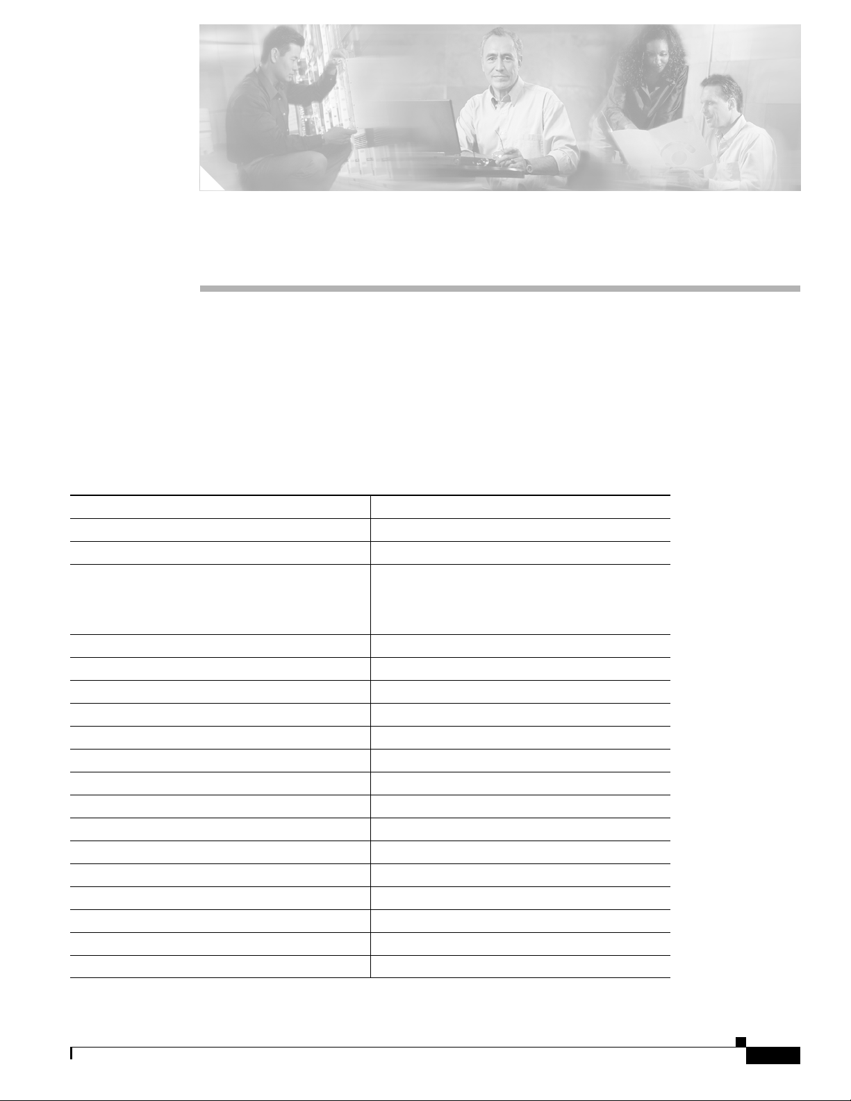
Table A-1 outlines the system specifications for the routers.
Table A-1 System Specifications
Description Design Specification
Physical Dimensions
Dimensions (H x W x D) 2.0 x 9.7 x 8.5 in. (5.1 x 24.6 x 21.6 cm)
Weight (does not include desktop power supply)
• Cisco 827-4V router: 1.5 lb. (0.68 kg)
A
• Cisco 827H router: 1.48 lb. (0.67 kg)
• Cisco 827 router: 1.48 lb. (0.67 kg)
Environmental Operating Ranges
Nonoperating temperature –4 to 149°F (–20 to 65°C)
Nonoperating humidity 5 to 95%, relative humidity
Nonoperating altitude 0 to 15,000 ft (4570 m)
Operating temperature 32 to 104°F (0 to 40°C)
Operating humidity 10 to 85% relative humidity
Operating altitude 0 to 10,000 ft (3000 m)
Router Power (Cisco 827, 827-4V, and SOHO 77)
AC input voltage 100 to 250 VAC
Frequency 50 to 60 Hz
Power consumption 29W
Router Power (Cisco 827H and SOHO 77H)
AC input voltage 100 to 240 VAC
Frequency 50 to 60 Hz
Power consumption 15W
78-6854-03
Cisco 827 and SOHO 77 Routers Hardware Installation Guide
A-1
Page 2
Port Connector Pinouts
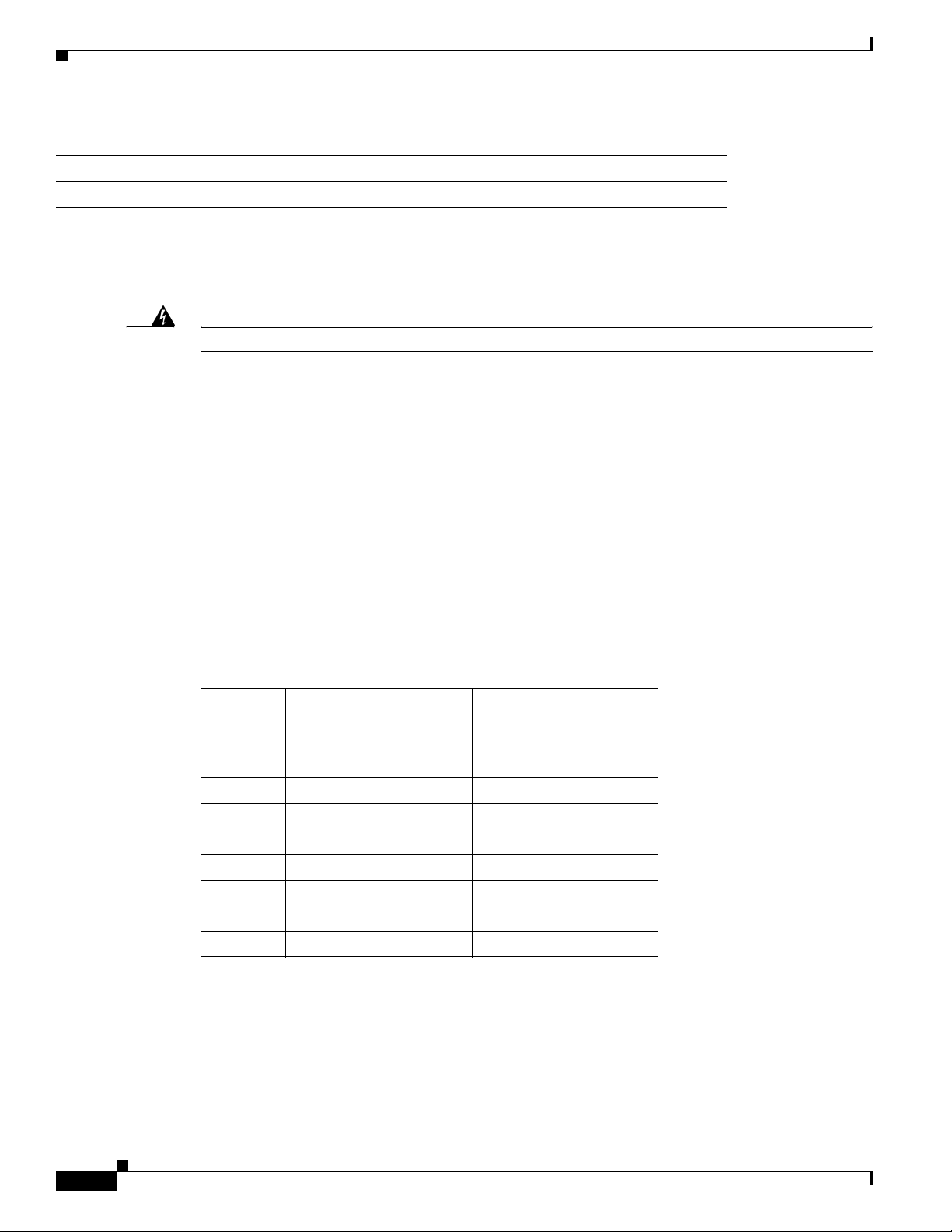
Table A-1 System Specifications (continued)
Description Design Specification
Telephone Port Power (Cisco 827-4V)
Voltage -24V and -71V
For information on regulatory compliance, refer to the Regulatory Compliance and Safety Information
for Cisco 827 Routers document that shipped with your router.
Appendix A Specifications and Cables
Warning
Ultimate disposal of this product should be handled according to all national laws and regulations.
Port Connector Pinouts
This section provides pinouts for the following connectors:
• Ethernet—See Table A-2.
• Console (for connecting a terminal or PC)—See Ta bl e A- 3.
• Telephone—See Tab le A-4.
• ADSL—See Tab l e A- 5
• Power—See Tab le A-6 and Ta b le A- 7 .
Table A-2 shows the Ethernet connector pinouts for the Cisco 827-4V, Cisco 827, Cisco 827H,
SOHO 77, and SOHO 77H routers.
Table A-2 Ethernet Connector Pinouts (RJ-45)
Function
(TO HUB/TO PC Button –
Pin
1TX+ RX+
2TX– RX–
3RX+ TX+
4 Unused Unused
5 Unused Unused
6RX– TX–
7 Unused Unused
8 Unused Unused
IN Position)
Function
(TO HUB/TO PC Button –
OUT Position)
A-2
Table A-3 shows the Ethernet connector pinouts for the Cisco 827-4V, Cisco 827, Cisco 827H,
SOHO 77, and SOHO 77H routers.
Cisco 827 and SOHO 77 Routers Hardware Installation Guide
78-6854-03
Page 3

Appendix A Specifications and Cables
Table A-3 Console Connector Pinouts (RJ-45)
Pin Function
1RTS
2DTR
3TXD
4GND
5GND
6RXD
7DSR
8CTS
Port Connector Pinouts
78-6854-03
Cisco 827 and SOHO 77 Routers Hardware Installation Guide
A-3
Page 4

Port Connector Pinouts
Appendix A Specifications and Cables
The console port is configured as a data communications equipment (DCE) device. The default
parameters for the console port are as follows:
• 9600 baud
• Eight data bits
• No parity
• One stop bit
Table A-4 shows telephone connector pinouts for the Cisco 827-4V router.
Table A-4 Cisco 827-4V Router Telephone Connector Pinouts (RJ-11)
Pin Function
1Unused
2Tip
3Ring
4Unused
Table A-5 shows ADSL connector pinouts for the Cisco 827-4V, Cisco 827, Cisco 827H, SOHO 77, and
SOHO 77H routers.
Table A-5 ADSL Connector Pinouts (RJ-11)
Pin Function
1 Loopback to pin 6
2Unused
3Tip
4Ring
5Unused
6 Loopback to pin 1
A-4
Cisco 827 and SOHO 77 Routers Hardware Installation Guide
78-6854-03
Page 5

Appendix A Specifications and Cables
Table A-6 shows the power connector pinouts for the Cisco 827, Cisco 827-4V, and SOHO 77 routers.
Table A-6 Cisco 827, Cisco 827-4V, and SOHO 77 Power Connector Pinouts
Pin Function
1ROF
2RTN
3+12
4 –12
5+5
6RTN
7 –71
8 –24
Table A-7 shows the power connector pinouts for the Cisco 827H and SOHO 77H routers.
Cabling Specifications
Table A-7 Cisco 827H and SOHO 77H Power Connector Pinouts
Pin Function
1ROF
2RTN
3AC_Lost
4Unused
5+5VF
6RTN
7Unused
8Unused
Cabling Specifications
This section provides specifications for the following Ethernet cables, which you might need to provide:
• Straight-through cables
• Crossover cables
This section also provides information on Ethernet and telephone cable distance limitations. (Telephone
cable connects a device to a telephone port.)
Ethernet Cable Specifications
Table A-8 lists the specifications for straight-through and crossover Ethernet cables.
78-6854-03
Cisco 827 and SOHO 77 Routers Hardware Installation Guide
A-5
Page 6

Cabling Specifications
Table A-8 Ethernet Cable Specifications
Type Category Shielding
10BASE-T Category 3 or 5 Shielded twisted-pair (STP)
10BASE-T – Unshielded twisted-pair (UTP)
Maximum Cable Distances
Table A-9 provides the maximum distances of Ethernet and telephone cables that you can use to connect
equipment to the router.
Table A-9 Maximum Cable Distances
Cable Maximum Distance
Ethernet cables 328 ft (100 m)
Telephone cable 500 ft (152 m)
Appendix A Specifications and Cables
A-6
Cisco 827 and SOHO 77 Routers Hardware Installation Guide
78-6854-03
 Loading...