

Page 1

CHA PTER
PIX 535
This chapter describes the installation of the PIX 535, and includes the following sections:
• PIX 535 Product Overview, page 7-1
• Installing the PIX 535, page 7-5
• PIX 535 Feature Licenses, page 7-6
• Installing Failover, page 7-8
• Installing LAN-Based Failover, page 7-9
• Replacing a Lithium Battery, page 7-10
• Installing a Memory Upgrade, page 7-11
• Installing a Circuit Board in the PIX 535, page 7-14
• Installing the PIX 535 DC Model, page 7-21
7
PIX 535 Product Overview
Note The PIX 535 chassis cover should not be removed. The user-serviceable components are accessed by a
removable tray at the back panel of each model. If you need to remove the PIX 535 chassis cover for any
reason, use the related information in the “Removing and Replacing the PIX 515/515E Chassis Cover”
section on page 4-13 as a guideline.
78-15170-03
Cisco PIX Security Appliance Hardware Installation Guide
7-1
Page 2
PIX 535 Product Overview
Chapter 7 PIX 535
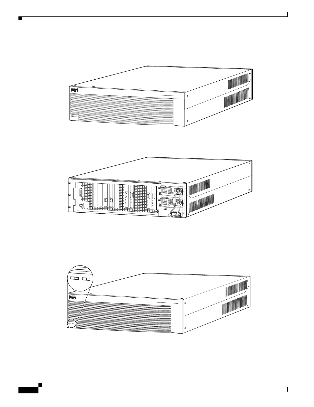
Figure 7-1 shows the front view of the PIX 535.
Figure 7-1 PIX 535 Front Panel
CISCO SECURITY PIX 535
POWER
ACTIVE
FIREWALL
S
E
R
IE
S
61915
Figure 7-2 shows the rear view of the PIX 535.
Figure 7-2 PIX 535 Rear Panel
S
T
A
T
U
S
S
T
A
T
U
S
61916
The PIX 535 has a fixed RJ-45 Console connector and a DB-15 Failover cable connector the USB port
is not used at the present time.
Figure 7-3 shows the PIX 535 front panel LEDs.
.
Figure 7-3 PIX 535 Front Panel LEDs
POW
ER ACTIVE
7-2
POWER
ACTIVE
Cisco PIX Security Appliance Hardware Installation Guide
CISCO SECURITY PIX 535
FIREWALL
S
E
R
IE
S
61918
78-15170-03
Page 3
Chapter 7 PIX 535
PIX 535 Product Overview
Table 7-1 lists the states of the PIX 535 front panel LEDs.
Table 7-1 PIX 535 Front Panel LEDs
LEDs State Description
POWER On Unit has power.
ACT On On when the unit is the active failover unit. If failover is present the light
is on when the unit is the active unit.
Off Off when the unit is in standby mode.
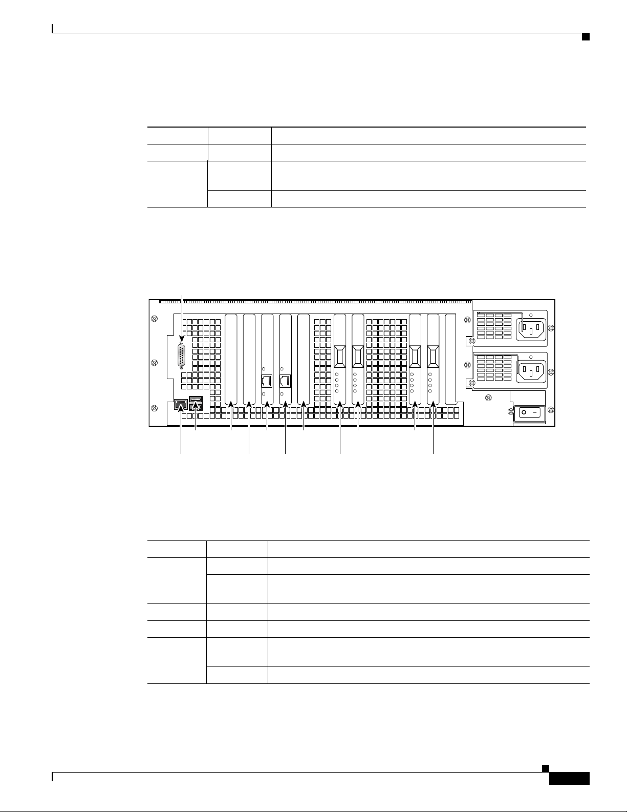
Figure 7-4 shows the PIX 535 rear panel LEDs.
Figure 7-4 PIX 535 Rear Panel LEDs
DB-15
failover
61919
Slot 1
Slot 0
RJ-45
USB
port
Slot 6Slot 8
Slot 7Console
Slot 5
Slot 4
Slot 2
Slot 3
Table 7-2 lists the states of the PIX 535 LEDs.
Table 7-2 PIX 535 Rear Panel LEDs
LEDs State Description
100 Mbps On 100 megabits per second 100BaseTX communication.
Off If the light is off during network activity, that port is using 10 megabits per
second data exchange.
ACT On Shows network activity.
LINK Shows that data is passing through that interface.
FDX On Shows that the connection uses full-duplex data exchange where data can
be transmitted and received simultaneously.
Off If this light is off, half duplex is in effect.
78-15170-03
Cisco PIX Security Appliance Hardware Installation Guide
7-3
Page 4

PIX 535 Product Overview
PIX 535 Network Interface Description
There are three separate buses for the nine interface slots in the PIX 535. The interfaces are counted from
right to left on the PIX 535.
The slots and buses are configured as follows:
• Slots 0 and 1-64-bit/66 MHz Bus 0
• Slots 2 and 3-64-bit/66 MHz Bus 1
• Slots 4 to 8-32-bit/33 MHz Bus 2
For optimum performance and throughput for the interface circuit boards, use the following guidelines:
• A total of two 10/100 Fast Ethernet interfaces, and support for up to twelve additional 10/100 Fast
Ethernet or nine Gigabit Ethernet interfaces are configurable with the unrestricted license.
• For best performance, the PIX-1GE-66 (66 MHz) circuit boards should be installed in a 64bit/66
MHz card slot, before they are installed in a 32-bit/33 MHz card slot. You can install up to nine
PIX-1GE-66 circuit boards in the PIX 535. If it is necessary to install PIX-1GE-66 circuit boards in
a 32-bit/33 MHz card slot, it would be best to use these for interfaces with lower throughput
requirements.
• If Stateful Failover is enabled for PIX-1GE-66 traffic, the failover link must be PIX-1GE-66. The
amount of Stateful Failover information is proportional to the amount of traffic flowing through the
PIX security appliance and if not configured properly, loss of state information or 256-byte block
depletion can occur.
• The PIX-1FE circuit board (33 MHz) can be installed in any bus or slot (32-bit/33 MHz or 64-bit/66
MHz). Up to nine PIX-1FE circuit boards, or up to two PIX-4FE, circuit boards can be installed.
The PIX-1FE circuit boards should be installed in the 32-bit/33 MHz card slots first.
Chapter 7 PIX 535
• The PIX-4FE card can only be installed in a 32-bit/33 MHz card slot and must never be installed in
a 64-bit/66 MHz card slot. Installation of this circuit board in a 64-bit/66 MHz card slot can cause
the system to hang at boot time.
• The PIX-4FE-66 may be installed in any slot. If there is a shortage of 64-bit/66 MHz card slots (the
slots are being used for 1GE-66 or PIX-VACPLUS), the PIX-4FE-66 should be installed in 32-bit/33
MHz card slot.
Note On the PIX-4FE card, port 0 is on the top and port 3 is on the bottom.
• Do not mix the PIX-1FE circuit boards with the PIX-1GE-66 circuit boards on the same 64-bit/66
MHz bus (Bus 0 or Bus 1). The overall speed of the bus is reduced by the lower speed circuit board.
• The PIX-1GE circuit board is not recommended for use in the PIX 535, as it can severely degrade
performance. It is only capable of half the throughput of the PIX-1GE-66 circuit board. If this circuit
board is detected in the PIX 535, a warning about degraded performance will be issued.
• The VPN Accelerator (PIX-VPN-ACCEL) can only be installed in a 32-bit/33 MHz card slot.
• The VPN Accelerator Card+ (PIX-VACPLUS) should always be installed in a 64-bit/66 MHz card
slot. VPN performance will be degraded by roughly a factor of 4 if this recommendation is not
followed.
For more information on the number of interfaces for each of the PIX Firewall models, click here.
7-4
Cisco PIX Security Appliance Hardware Installation Guide
78-15170-03
Page 5

Chapter 7 PIX 535
Table 7-3 lists the relative throughput of the Gigabit Ethernet combinations.
Table 7-3 Relative Throughput of Gigabit Ethernet Combinations
Gigabit Ethernet Card Bus Type
PIX-1GE-66 64/66 No 100%
PIX-1GE-66 64/66 Yes 50%
PIX-1GE-66 32/33 No 25%
PIX-1GE 64/66 No 50%
PIX-1GE 32/33 No 25%
Installing the PIX 535
This section includes the following topics:
• Before Installing the PIX 535, page 7-5
Installing the PIX 535
Shared with
33 MHz Device Speed
• Mounting the PIX 535, page 7-5
• PIX 535 Network Interface Installation, page 7-6
Before Installing the PIX 535
Observe the following before installing the PIX security appliance:
• Review the safety precautions outlined in the Regulatory Compliance and Safety Information
document.
• Place the PIX security appliance on a stable work surface.
Mounting the PIX 535
To mount the PIX 535 on a rack, perform the following steps:
Step 1 Attach the mounting brackets to the unit using the supplied screws.
Step 2 Attach the brackets to the holes near the front on both sides of the unit.
Step 3 Attach the unit to the equipment rack.
78-15170-03
Cisco PIX Security Appliance Hardware Installation Guide
7-5
Page 6

PIX 535 Feature Licenses
PIX 535 Network Interface Installation
Note If your PIX security appliance model supports a failover configuration, complete the steps that follow
only on the active (primary) unit.
To connect interfaces to the PIX 535, perform the following steps:
Step 1 Connect the cable so that you have either a DB-9 or DB-25 connector on one end as required by the serial
port for your computer, and the other end is the RJ-45 connector.
Note Use the Console port to connect to a computer to enter configuration commands. Locate the
serial cable from the accessory kit. The serial cable assembly consists of a null modem cable
with RJ-45 connectors, and one DB-9 connector and a DB-25 connector.
Step 2 Connect the cable to the PIX 535 RJ-45 Console connector port and connect the other end of the cable
to the serial port connector on your computer.
Chapter 7 PIX 535
Step 3 Connect the inside, outside, or perimeter network cables to the interface ports. Starting from the right
and moving left, the connectors are Ethernet 0, Ethernet 1, Ethernet 2, and so forth. The maximum
number of allowed interfaces is 8. The inside or outside network connections can be made to any
available interface port on the PIX 535.
Note If you have a second PIX security appliance to use as a failover unit, install the failover feature
and cable as described in the “Installing Failover” section on page 7-8.
Caution Do not power on the failover units until the active unit is configured.
Step 4 When you are ready to start the PIX 535, power on the unit from the switch at the rear of the unit.
PIX 535 Feature Licenses
If you have the PIX-535-UR unrestricted feature license, the following options are available:
• If you have a second PIX 535 to use as a failover unit, install the failover feature and cable as
described in the “Installing Failover” section on page 7-8.
• If needed, install the PIX security appliance syslog server as described in the logging command page
in the command reference online at:
http://cisco.com/en/US/products/sw/secursw/ps2120/prod_command_reference_list.html
7-6
• If you need to install an optional circuit board, refer to the “Installing a Circuit Board in the
PIX 535” section on page 7-14.
• If you need to install additional memory, refer to the “Installing a Memory Upgrade” section on
page 7-11.
Cisco PIX Security Appliance Hardware Installation Guide
78-15170-03
Page 7

Chapter 7 PIX 535
For information on upgrading feature licenses or downloading the latest software versions, refer to the
configuration guide online at:
http://www.cisco.com/en/US/products/sw/secursw/ps2120/prod_configuration_guides_list.html.
This section includes the following topics:
VPN Accelerator Card, page 7-7
VPN Accelerator Card+, page 7-7
VPN Accelerator Card
The VPN Accelerator Card (VAC) for the Cisco PIX security appliance series is a card that provides
high-performance, tunneling and encryption services suitable for site-to-site and remote access applications.
The VAC is integrated with PIX 535 unrestricted (UR) and failover (FO) bundles. You can also purchase the
VAC as a spare for use with PIX 535 units that have a restricted (R) license.
Note Installing a VAC and an 82557 based FE card on the PIX 535 could result in a system hang.
PIX 535 Feature Licenses
VPN Accelerator Card+
The VAC+ is a 64-bit/66 MHz PCI card that provides faster tunneling and encryption services for Virtual
Private Network (VPN) remote access, and site-to-site intranet and extranet applications, than the VAC.
Each VAC+ occupies a single PCI slot in the system. The VAC+ is supported on any chassis that runs
Version 6.3 software, has an appropriate license to run VPN software, and at least one PCI slot available.
While the VAC continues to be supported in Version 6.3, if both types of cards, the VAC and the VAC+,
are installed in a system running Version 6.3, the VAC card is ignored. The VAC+ runs at both
32-bit/33MHz and 64-bit/66 MHz, and does not slow down the bus when other 66 MHz cards are
installed. We strongly recommend that you install the VAC+ in a 64bit/66 MHz slot. Performance is degraded
if this recommendation is not followed.
The VAC+ driver supports the following:
• 3DES, DES, AES, SHA1, MD5 for (IPSec) ESP protocol (For AES, only the CBC mode and key
sizes of 128, 192, and 256 bits are supported).
• SHA1, MD5 for the (IPSec) AH protocol.
• Load sharing ESP and AH activity between up to three VAC+.
• Diffie-Hellman public key and shared secret generation.
• Any other crypto-related activity uses a software implementation.
78-15170-03
Cisco PIX Security Appliance Hardware Installation Guide
7-7
Page 8
Installing Failover
Installing Failover
To set up a failover connection, perform the following steps:
Step 1 Power off both the primary and secondary units.
Note Both chassis must be the same model number, have at least as much RAM, have the same Flash
memory size, and be running the same software version. Note that the PIX-4FE and PIX-4FE-66
cards are considered equivalent and interchangeable. You can install a PIX-4FE in the primary
unit and a PIX-4FE-66 in the secondary unit, as long as you install them in the same slot number
of each chassis. For example, if you install a PIX-4FE in Slot 1 of the primary unit, you must
also install the PIX-4FE-66 in Slot 1 of the secondary unit.
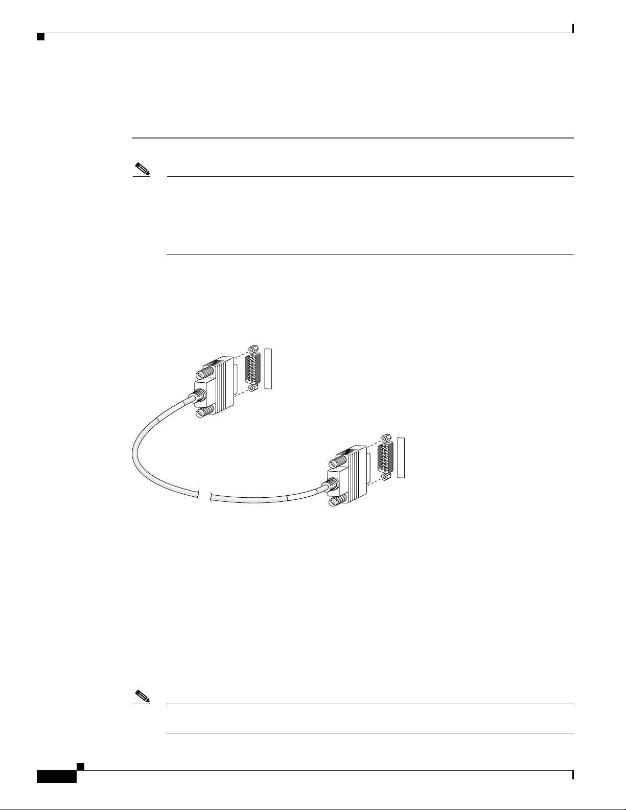
Step 2 Locate the failover cable (shown in Figure 7-5). This cable is shipped separately from the PIX security
appliance. The cable is labeled “Primary” on one end and “Secondary” on the other.
Install the cable for the PIX 535 as shown in Figure 7-5.
Chapter 7 PIX 535
Figure 7-5 PIX 535 Failover Cable Connection
F
A
I
L
O
V
E
R
Y
R
A
M
I
R
P
Primary end
F
A
I
L
O
V
E
R
Y
R
A
D
N
O
C
E
S
12395
Secondary end
Step 3
Connect the Primary end of the failover cable to the first PIX security appliance, that is, the one you have
already configured.
Step 4 Connect the Secondary end of the failover cable to the standby unit.
Step 5 Connect a power cord to the power connector on the rear panel of each unit, and the other end of each
power cord to (preferably separate) power outlets.
Step 6 If you are using Stateful Failover, use one of the following types of connections, that is appropriate for
your system, between the dedicated interfaces on the PIX security appliance:
• Category 5 crossover cable directly connecting the primary unit to the secondary unit
7-8
• 100BaseTX full duplex on a dedicated switch or dedicated VLAN of a switch
• 1000BaseTX full duplex on a dedicated switch or dedicated VLAN of a switch
Note For Stateful Failover on the PIX 535, you must use a Gigabit Ethernet (GE) failover link with
GE interfaces.
Cisco PIX Security Appliance Hardware Installation Guide
78-15170-03
Page 9

Chapter 7 PIX 535
Caution Do not turn the power on until the units are connected and the primary unit is configured completely.
Step 7 Power the primary unit on first, then power on the secondary unit. Within a few seconds, the active unit
automatically downloads its configuration to the standby unit.
If the primary unit fails, the secondary unit automatically becomes active.
Note All enabled interfaces must be connected between the active and standby units. Only configure the active
unit. On the PIX 535, the active unit is indicated by the ACT LED on the front panel (see Figure 7-1).
Installing LAN-Based Failover
LAN-based failover supports failover between two units connected over a dedicated Ethernet interface.
LAN-based failover eliminates the need for a special failover cable and overcomes the distance
limitations imposed by the failover cable.
Installing LAN-Based Failover
Note Both PIX security appliances must be the same model number, have the same amount of RAM, Flash
memory, number and type of interfaces, and be running the same software version.
To set up a LAN-based failover connection, perform the following steps:
Step 1 Disconnect both PIX security appliance, so that there is no traffic flow between them. If the failover
cable is connected to the PIX security appliance, disconnect it.
Step 2 Configure the PIX security appliance for LAN-based failover. Refer to the chapter on configuring
LAN-based failover in the configuration guide online at:
http://www.cisco.com/en/US/products/sw/secursw/ps2120/prod_configuration_guides_list.html
Step 3 Power off both units.
Step 4 Connect the LAN failover interfaces to the dedicated switch/hub, as shown in Figure 7-6.
Note A dedicated LAN interface and a dedicated switch (or VLAN) is required to implement
LAN-based failover. You cannot use a crossover Ethernet cable to connect the two PIX security
appliances.
78-15170-03
Cisco PIX Security Appliance Hardware Installation Guide
7-9
Page 10

Replacing a Lithium Battery
Figure 7-6 LAN-Based Failover Connections
Chapter 7 PIX 535
Step 5
PIX 535
S
T
A
T
U
S
S
T
A
T
U
S
PIX 535
S
T
A
T
U
S
S
T
A
T
U
S
87366
87368
Dedicated Ethernet
interface
Dedicated Ethernet
interface
Hub/switch
If you are using Stateful Failover, use one of the following types of connections, that is appropriate for
your system, between the dedicated interfaces on the PIX security appliance:
• 100BaseTX full duplex on a dedicated switch or dedicated VLAN of a switch
• 1000BaseTX full duplex on a dedicated switch or dedicated VLAN of a switch
Note For Stateful Failover on the PIX 535, you must use a Gigabit Ethernet (GE) failover link with
GE interfaces.
Caution Do not turn the power on until the units are connected and the primary unit is configured completely.
Step 6 Power the primary unit on first, then power on the secondary unit. Within a few seconds, the active unit
automatically downloads its configuration to the standby unit.
If the primary unit fails, the secondary unit automatically becomes active.
Replacing a Lithium Battery
The PIX security appliance has a lithium battery on its main circuit board. This battery has an operating
life of about ten years. When the battery loses its charge, the PIX security appliance cannot function.
The lithium battery is not a field-replaceable unit (FRU). Contact Cisco TAC to replace the battery.
Note Do not attempt to replace this battery yourself.
Warning
Danger of explosion exists if the lithium battery is incorrectly replaced. Replace only with the same
or equivalent type recommended by the manufacturer. Dispose of used batteries according to the
manufacturer's instructions.
7-10
Cisco PIX Security Appliance Hardware Installation Guide
78-15170-03
Page 11

Chapter 7 PIX 535
Installing a Memory Upgrade
The following statement applies to DC models only:
Installing a Memory Upgrade
Warning
Before performing any of the following procedures, ensure that power is removed from
the DC circuit. To ensure that all power is OFF, locate the circuit breaker on the panel
board that services the DC circuit, switch the circuit breaker to the OFF position, and
tape the switch handle of the circuit breaker in the OFF position.
The following statement applies to both AC and DC models:
Warning
Caution Running the PIX security appliance without the chassis cover causes the system to overheat and
Before working on a system that has an On/Off switch, turn OFF the power and unplug the
power cord.
damages the electrical components. If you remove the chassis cover to perform a maintenance
procedure, like installing additional memory, be sure to replace the cover after you have finished
the procedure.
To install additional system memory, perform the following steps:
Step 1 Power off the security appliance.
Step 2 Remove all cables connected to the security appliance and unplug it from its power source.
Step 3 If the chassis is rack-mounted, remove it from the rack and set it on flat, stable surface.
Step 4 Unpack the items in the memory upgrade kit.
Step 5 Locate the grounding strap in the upgrade kit. Connect one end of the strap to an unpainted metal surface
on the PIX security appliance chassis. Attach the other end to your wrist, making sure that it contacts
your bare skin.
Step 6 At the rear panel of the chassis, loosen the attachment screws that hold the component tray in place and
slide the tray out.
78-15170-03
Cisco PIX Security Appliance Hardware Installation Guide
7-11
Page 12

Installing a Memory Upgrade
Step 7 Locate the system memory sockets (see Figure 7-7).
Populate memory Bank 0 first, then Bank 1. Memory sockets J40 and J43 comprise Bank 0; J41 and J44
comprise Bank 1. The PIX security appliance comes with 512 MB of RAM installed by default, so
Bank 0 (J40 and J43) should be populated already. Install the additional 512 MB of RAM in Bank 1 (J41
and J44).
The memory DIMM pair that comprises a memory bank must be identical. Make sure that memory from
the same vendor is placed together in the each memory bank (J40 and J43 in Bank 0 or J41 and J44 in
Bank 1).
Figure 7-7 System Memory Location on the PIX 535 Component Tray
Chapter 7 PIX 535
7-12
Cisco PIX Security Appliance Hardware Installation Guide
78-15170-03
Page 13

Chapter 7 PIX 535
Step 8 Install the first DIMM strip in socket J41 and the second DIMM strip in socket J44, as shown in
Installing a Memory Upgrade
Figure 7-8 and Figure 7-9.
a. Carefully grasp the DIMM strip from either end, being careful not to touch the components on the
strip. Note that the DIMM strip is notched, which prevents it from being installed incorrectly. So,
do not force installation.
b. Open the two plastic wing connectors at the sides of the memory socket, insert the DIMM strip, and
close the wing connectors to secure it in place.
Figure 7-8 Inserting a DIMM Memory Strip in the PIX 535
DIMM
89067
J45
J44
J43
Wing
connector
J42
J41
J40
Figure 7-9 Securing a DIMM Memory Strip in the PIX 535
Step 9
Reinstall the component tray and the screws that hold the assembly in place.
Step 10 Remove the grounding wrist-strap.
78-15170-03
Step 11 Rack-mount the chassis or place it on a flat, stable surface.
Cisco PIX Security Appliance Hardware Installation Guide
7-13
Page 14

Installing a Circuit Board in the PIX 535
Step 12 Reconnect all cables to the security appliance and plug it into its power source.
Step 13 Power on the security appliance.
Note You can verify that the security appliance recognizes the new RAM memory that you installed by
looking at the system startup messages or by entering the show version command.
Installing a Circuit Board in the PIX 535
The 4-port 64 bit/66 MHz FE card (PIX-4FE-66) is supported in software Versions 6.3, 6.2(2), 6.1(4),
and 5.2(9), and later versions. These are the minimum software versions that support the card.
Note The PIX-4FE card continues to be supported but is no longer manufactured. The PIX-4FE and
PIX-4FE-66 cards are considered equivalent and interchangeable. You can install a PIX-4FE in the
primary unit and a PIX-4FE-66 in the secondary unit, as long as you install them in the same slot number
of each chassis. For example, if you install a PIX-4FE in Slot 1 of the primary unit, you must also install
the PIX-4FE-66 in Slot 1 of the secondary unit.
Chapter 7 PIX 535
The new card has the following characteristics:
• Includes an Intel 21154BE bridge and four Intel 82559 Ethernet MAC/PHY devices.
• Supports 10/100 mbps full/half-duplex operation on each port.
• Retains bus performance when installed with other 66-MHz devices.
• Does not support auto MDI/MDIX operation.
This section includes the following topics:
• PIX 535 Circuit Board Options, page 7-14
• Circuit Board Slot Description, page 7-16
• Installing a Circuit Board, page 7-17
• 16 MB Flash Circuit Board, page 7-18
• VPN Accelerator Circuit Board, page 7-20
• Gigabit Ethernet Circuit Board, page 7-20
PIX 535 Circuit Board Options
Table 7-4 lists the optional circuit board combinations that are available for the PIX 535. A maximum
of eight interfaces are available with a restricted license, and 14 interfaces are available with an
unrestricted license.
7-14
Note Table 7-4 applies only to PIX security appliance Version 6.1(1) and later. Earlier versions of
PIX security appliance support fewer interface options.
For more information on the number of interfaces for each of the PIX Firewall models, click here.
Cisco PIX Security Appliance Hardware Installation Guide
78-15170-03
Page 15

Chapter 7 PIX 535
Installing a Circuit Board in the PIX 535
Table 7-4 PIX 535 Interface Options
Restricted Interface Options Unrestricted Interface Options
8 GE 9 GE
8 GE + 1 VPN Accelerator 8 GE + 1 FE
7 GE + 1 FE 8 GE + 1 VPN Accelerator
7 GE + 1 FE + 1 VPN Accelerator 7 GE + 2 FE
6 GE + 2 FE 7 GE + 1 FE + 1 VPN Accelerator
6 GE + 2 FE + 1 VPN Accelerator 6 GE + 3 FE
5 GE + 3 FE 6 GE + 2 FE + 1 VPN Accelerator
5 GE + 3 FE + 1 VPN Accelerator 5 GE + 4 FE
4 GE + 4 FE 5 GE + 3 FE + 1 VPN Accelerator
4 GE + 4 FE + 1 VPN Accelerator 5 GE + 1 FE + 1 4-port FE
3 GE + 5 FE 5 GE + 1 FE + 1 4-port FE + 1 VPN Accelerator
3 GE + 5 FE + 1 VPN Accelerator 4 GE + 5 FE
2 GE + 6 FE 4 GE + 4 FE + 1 VPN Accelerator
2 GE + 6 FE + 1 VPN Accelerator 4 GE + 2 FE + 1 4-port FE
2 GE + 2FE + 1 4-port FE 4 GE + 2 FE + 1 4-port FE + 1 VPN Accelerator
2 GE + 2FE + 1 4-port FE + 1 VPN
3 GE + 6 FE
Accelerator
1 GE + 3 FE + 1 4-port FE 3 GE + 5 FE + 1 VPN Accelerator
1 GE + 3 FE + 1 4-port FE + 1 VPN
3 GE + 1 4-port FE + 3 FE
Accelerator
8 FE 3 GE + 5 FE + 1 VPN Accelerator
8 FE + 1 VPN Accelerator 3 GE + 3 FE + 1 4-port FE
4 FE + 1 4-port 3 GE + 3 FE+ 1 4-port FE + 1 VPN Accelerator
4 FE + 1 4-port + 1 VPN Accelerator 2 GE + 2 4-port FE
2 4-port + 1 VPN Accelerator 2 GE + 2 4-port FE + 1 VPN Accelerator
2 GE + 4 FE +1 4-port FE
2 GE + 4 FE + 1 4-port FE + + 1 VPN Accelerator
2 GE + 7 FE
2 GE + 6 FE + 1 VPN Accelerator
9 FE
8 FE + 1 VPN Accelerator
2 4-port FE + 2 FE
2 4-port FE + 2 FE + 1 VPN Accelerator
1 4-port FE card + 6 FE
1 4-port FE card + 6 FE + 1 VPN Accelerator
1GE + 1FE + 2 x 4FE cards
78-15170-03
Cisco PIX Security Appliance Hardware Installation Guide
7-15
Page 16

Installing a Circuit Board in the PIX 535
Circuit Board Slot Description
There are nine circuit board slots (see Figure 7-10) using three separate buses for the PIX 535.
Figure 7-10 PIX 535 Back Panel Detail
DB-15
failover
USB
port
Slot 7Console
RJ-45
Chapter 7 PIX 535
61919
Slot 6Slot 8
Slot 5
Slot 4
Slot 2
Slot 3
Slot 1
Slot 0
The slots and buses are configured as follows:
• Slots 0 and 1—64-bit/66 MHz Bus 0
• Slots 2 and 3—64-bit/66 MHz Bus 1
• Slots 4 to 8—32-bit/33 MHz Bus 2
For optimum performance and throughput for the interface circuit boards, you must use the following
guidelines:
• A total of two 10/100 Fast Ethernet interfaces, and support for up to twelve additional 10/100 Fast
Ethernet or nine Gigabit Ethernet interfaces are configurable with the unrestricted license
• PIX-1GE-66 (66 MHz) circuit boards can be installed in any slot, but should be installed in the
64-bit/66 MHz Bus first. Up to eight PIX-1GE-66 circuit boards can be installed.
• The FE circuit board (33 MHz) can be installed in any bus or slot (32-bit/33 MHz or
64-bit/66 MHz). Up to eight single-port FE circuit boards or up to two four-port FE circuit boards
can be installed.
–
The four-port FE circuit board should only be installed in the 32-bit/33 MHz Bus.
Note The numbering of the FE circuit boards in monitor mode begins at the 32-bit slots; do not
install any FE circuit boards in the 64-bit slots.
• Do not mix the 33 MHz circuit boards with the 66 MHz GE circuit boards on the same
64-bit/66 MHz bus (Bus 0 or Bus 1). The overall speed of the bus will be reduced by the lower speed
circuit board.
• The VPN Accelerator circuit board should only be installed in the 32-bit/33 MHz Bus.
For more information on the number of interfaces for each of the PIX Firewall models, click here.
7-16
Cisco PIX Security Appliance Hardware Installation Guide
78-15170-03
Page 17

Chapter 7 PIX 535
Installing a Circuit Board
Note It is not necessary to remove the chassis cover on the PIX 535 to install or replace a circuit board. A
component tray, that slides out from the rear panel, contains slots for installing circuit boards and
memory boards.
To install a circuit board in the PIX 535, perform the following steps:
Step 1 Locate the grounding strap from the accessory kit. Fasten the grounding strap to your wrist so that it
contacts your bare skin. Attach the other end to bare metal on the PIX 535 chassis.
Figure 7-11 The Component Tray at the Back of the PIX 535
Installing a Circuit Board in the PIX 535
S
T
A
T
U
Step 2
S
S
T
A
T
U
S
Loosen the attachment screws from the rear panel of the component tray and slide the tray out.
61917
Step 3 Select a slot for the circuit board and remove the screw and slot cover plate from the back panel on the
component tray.
Step 4 Install the circuit board into the slot. The front plate on the circuit board should be against the slot
opening on the component tray back panel.
Step 5 Use the screw that was removed in Step 3 to attach the circuit board front plate to the component tray
rear panel.
Step 6 Reinstall the component tray and tighten the attachment screws.
78-15170-03
Cisco PIX Security Appliance Hardware Installation Guide
7-17
Page 18

Installing a Circuit Board in the PIX 535
Figure 7-12 4-Port Circuit Board Overlap
Chapter 7 PIX 535
Overlap
Note If you are installing a 4-port circuit board, note that the circuit board will overlap the slot
connector on the motherboard. This does not affect the use or operation of the circuit board.
Figure 7-12 illustrates how this appears.
16 MB Flash Circuit Board
Along with upgrading your Flash memory to 16 MB, the PIX security appliance 16 MB Flash circuit
board includes pre-installed PIX security appliance software and a UR (unrestricted) 56-bit DES
encryption license. The 16 MB Flash circuit board installs into the PIX security appliance ISA slot.
27884
7-18
Cisco PIX Security Appliance Hardware Installation Guide
78-15170-03
Page 19

Chapter 7 PIX 535
Installing a Circuit Board in the PIX 535
An illustration of the 16 MB Flash circuit board is shown in Figure 7-13.
Figure 7-13 16 MB Flash Circuit Board
33011
You must observe the following when installing a 16 MB Flash circuit board:
• The PIX security appliance must have a minimum of 32 MB of RAM memory.
• You must obtain a new activation key if you use 3DES.
• The PIX security appliance should not be downgraded to a software revision lower than 5.0(3) after
the new software from the 16 MB circuit board is installed.
• If you downgrade from software Version 5.3 to 5.2 or lower, you will lose private data (keys,
certifications, and CRLs) that are stored in Flash memory. You need to use the clear flashfs
command, downgrade 5.0 | 5.1 | 5.2 options if your PIX security appliance has 16 MB Flash
memory, private data stored in the Flash memory, and you used the ca save all command to save
these items in Flash memory.
To install the 16 MB Flash circuit board, perform the following steps:
Step 1 Record the present PIX security appliance serial number.
Step 2 Record the new serial number from the 16 MB Flash circuit board.
After installation, the serial number of the PIX security appliance becomes the serial number supplied
with the 16 MB Flash circuit board.
Step 3 Create a backup of your present configuration (to use later to reconfigure your system).
Step 4 Obtain a new Activation key (if using 3DES).
78-15170-03
Cisco PIX Security Appliance Hardware Installation Guide
7-19
Page 20

Installing a Circuit Board in the PIX 535
Step 5 Remove any previously installed Flash memory circuit boards from the unit.
Step 6 The jumper on the PIX security appliance 16 MB Flash circuit board must not be removed or
repositioned. The PIX security appliance system will not work if this jumper is moved.
Step 7 Install the 16 MB Flash circuit board into an available ISA slot in the PIX security appliance chassis.
VPN Accelerator Circuit Board
The VPN Accelerator (PIX-VPN-ACCEL) is an encryption and accelerator circuit board. The VPN
Accelerator uses a PCI interface and therefore can only be installed in PIX security appliance platforms
with PCI slots. The VPN Accelerator begins to function immediately after installation without the need
of special installation configurations.
Note The new VPN Accelerator cannot be used with the former PIX security appliance IPSec accelerator in
the same chassis. The PIX security appliance IPSec accelerator was also known as the Private Link card.
Chapter 7 PIX 535
An illustration of the VPN Accelerator is shown in Figure 7-14.
Figure 7-14 PIX Security Appliance VPN Accelerator Circuit Board
Gigabit Ethernet Circuit Board
61921
7-20
PIX security appliance supports 1000 Mbps (Gigabit) Ethernet. The Gigabit Ethernet circuit board has
only one hardware speed and supports the following duplex options:
• 1000SXfull—Forces full-duplex operation
• 1000BaseSX—Forces half-duplex operation
• 1000auto—Auto negotiates full or half duplex
Cisco PIX Security Appliance Hardware Installation Guide
78-15170-03
Page 21

Chapter 7 PIX 535
Note You must use a GE failover link when connecting the PIX 535 with GE interfaces.
Installing the PIX 535 DC Model
The Gigabit Ethernet circuit board and the fiber optic cable connection are shown in Figure 7-15.
Figure 7-15 Gigabit Ethernet Circuit Board
33010
TX
RX
LINK
The Gigabit Ethernet circuit board has three LEDs:
• TX—Transmitting data
• RX—Receiving data
• LINK—The Gigabit Ethernet circuit board has established a network connection
Installing the PIX 535 DC Model
Warning
Before performing any of the following procedures, ensure that power is removed from the DC circuit.
To ensure that all power is OFF, locate the circuit breaker on the panel board that services the DC
circuit, switch the circuit breaker to the OFF position, and tape the switch handle of the circuit
breaker in the OFF position.
78-15170-03
To install the PIX 535 DC power model, perform the following steps:
Step 1 Remove the blank cover plate, if a blank cover plate is installed on the PIX 535.
Step 2 Read the Regulatory Compliance and Safety Information document for your respective software version.
Cisco PIX Security Appliance Hardware Installation Guide
7-21
Page 22

Installing the PIX 535 DC Model
Step 3 Terminate the DC input wiring on a DC source capable of supplying at least 15 amps. A 15-amp circuit
breaker is required at the -48 VDC facility power source. An easily accessible disconnect device should
be incorporated into the facility wiring.
Step 4 Be sure the PIX 535 power is off by checking the power switch at the rear of the unit.
Step 5 As shown in Figure 7-16, the PIX 535 is equipped with two grounding holes at the back of the unit,
which you can use to connect a two-hole grounding lug to the PIX 535. Use M3.5 x 7 mm thread-forming
screws to connect a copper standard barrel grounding lug to the holes. The PIX 535 requires a grounding
lug where the distance between the center of each hole is 0.56 inches. A grounding lug is not supplied
with the PIX 535.
Figure 7-16 Attaching a Grounding Lug to the PIX 535 DC
Chassis grounding receptacles
S
T
A
T
U
S
Ð
+
S
T
A
T
U
S
Ð
+
Chapter 7 PIX 535
52714
Screws
Grounding lug
Grounding wire
Step 6 Ensure that power is removed from the DC circuit. To ensure that all power is OFF, locate the circuit
breaker on the panel board that services the DC circuit, switch the circuit breaker to the OFF position,
and tape the switch handle of the circuit breaker in the OFF position.
Step 7
Step 8 Refer to Figure 7-17 and insert the ground wire into the connector for the earth ground and tighten the
Strip the ends of the wires for insertion into the power connect lugs, located to the left of the power switch.
screw on the connector. Using the same method as for the ground wire, connect the negative wire and
then the positive wire.
Figure 7-17 Attaching DC Power Cables
–
+
11779
7-22
Cisco PIX Security Appliance Hardware Installation Guide
78-15170-03
Page 23

Chapter 7 PIX 535
Step 9 Reconnect power to the PIX 535. After wiring the DC power supply, remove the tape from the circuit
Step 10 If needed, install the interface boards as described in the “Installing a Circuit Board in the PIX 535”
Step 11 Power on the unit from the switch at the rear of the unit.
Note If you need to power cycle the DC PIX 535, wait at least 5 seconds between powering off the unit and
Installing the PIX 535 DC Model
breaker switch handle and reinstate power by moving the handle of the circuit breaker to the ON position.
section on page 7-14.
powering it back on.
Your unit is now ready to configure. Refer to the configuration guide online at:
http://www.cisco.com/en/US/products/sw/secursw/ps2120/prod_configuration_guides_list.html.
78-15170-03
Cisco PIX Security Appliance Hardware Installation Guide
7-23
Page 24

Installing the PIX 535 DC Model
Chapter 7 PIX 535
7-24
Cisco PIX Security Appliance Hardware Installation Guide
78-15170-03
 Loading...