

Page 1

Cisco Model DPQ3925 8x4
Notices ................................................................................................................. 106
DOCSIS 3.0 Wireless Residential
Gateway with Embedded Digital
Voice Adapter User Guide
In Thi s Doc um en t
IMPORTA NT SAFETY INSTRUCTIONS............................................................. 2
Introduction .......................................................................................................... 14
What's In th e Carto n? ........................................................................................... 16
Front Panel Description ....................................................................................... 17
Back Panel Desc ription ........................................................................................ 18
What Are t he Syste m Requirements for I nte rnet Servic e? ................................ 19
How Do I Subscribe to High-Sp eed Int ernet a nd Telep hone S er vic e?............. 20
Where Is the Best Locatio n for My DOCSIS Resid ential Gateway? ................. 22
How Do I Mount the Modem on a Wall? (Optional)......................................... 23
What Are t he Requirements for Telep hone S er vice?......................................... 26
How Do I Co nnect My Gat eway for Internet and Telep hone Se rvice? ............ 27
How Do I Maintain the Battery? (Optional)....................................................... 30
How Do I Configu re My DOCSIS Resid ent ial Gateway? ................................. 32
Configure Wireless Settings ................................................................................ 41
Configure S ecurity ............................................................................................... 57
Control Access to the Gateway ........................................................................... 66
Configure Appl ica tions a nd Gaming .................................................................. 75
Manage the Gateway ........................................................................................... 81
Monitor Gateway Status ...................................................................................... 90
Frequently Asked Questio ns ............................................................................... 97
Tips for Improv ed Performa nce ........................................................................ 101
Fro nt Pane l LED Status Indica t or Functio ns .................................................... 102
Page 2
IMPORTANT SAFETY INSTRUCTIONS
IMPORTANT SAFETY INSTRUCTIONS
Notice to Installers
The servicing i nstructions in this notice a re for use by qual ified service personnel only. To r educe the
risk of electric shock, do not perform any servi cing other than that contained in the operating
instructions, unless you are qualified to do so.
Notice à l’attent ion des in st allateu rs de réseaux câblés
Les instructions r elatives aux inter ventions d’ entretien, four nies d ans la prés ente noti ce, s’ad r essent
exclusivement au per sonnel technique qual ifié. Pour rédui re l es r isques de chocs électriques, n’ effectuer
aucune interventi on autre que celles décrites d ans le mode d'empl oi et l es instructions rela tives au
fonctionnement, à moins que vous ne soyez qualifié pour ce faire.
2 OL-30824-01
Page 3
IMPORTANT SAFETY INSTRUCTIONS
Mitteilung für CA TV -Techniker
Die in dieser Mitteilung aufgeführten Wartungsanweisungen sind ausschließlich für qualifiziertes
Fachper sonal bestimmt. Um d ie Gefahr eines el ektrischen Schlags zu reduzier en, sollten Si e keine
Wartungsarbeiten d urchführen, d ie nicht ausdrücklich in der B edienungsanleitung aufgeführt si nd,
außer Sie sind zur Durchführung solcher Arbeiten qualifiziert.
Aviso a los instaladores de sistem as CA TV
Las i nstrucci ones de r eparación contenidas en el pres ente aviso son para uso exclusivo por parte de
pers ona l de ma nteni miento cua lificado. Con el fin d e reducir el riesgo d e descar ga eléctri ca , no real ice
ninguna otra operación de reparación distinta a las contenidas en las instrucciones de funcionamiento, a
menos que posea la cualificación necesaria para hacerlo.
20080814_Installer820_Intl
OL-30824-01 3
Page 4

IMPORTANT SAFETY INSTRUCTIONS
2)
Keep these i nstructi ons.
3)
Heed all warnings.
6)
Clean only with dr y cloth.
7)
Do not block any ventilation openings. Install i n accord ance w ith the manufa cturer's
8)
Do not install near any heat sources such as radiators, heat registers, stoves, or other
9)
Do not d efeat the safety pur pose of the pol ariz ed or gr oundi ng-type plug. A
Use only with the cart, stand, tripod, bracket, or table specified by the manufacturer,
13)
Unplug this apparatus during lightning storms or w hen unused for long periods of
damaged, liquid has been spilled or objects have fallen into the apparatus, the
WARNING: Avoid electric shock a nd fire hazard! If this p r oduct connects to co a x ia l
cable wiring, be sure the cable system is grounded (earthed). Grounding provides some
IMPORTANT SAFETY I NSTRUCTIO NS
1) Read these ins tr uctions.
4) Follow all instructions.
5) Do not use this appa r a tus near wa ter.
instructions.
apparatus (including amplifiers) that produce heat.
polar ized plug has two bl ades w ith one w ider than the other. A grounding-type
plug has two blades and a third grounding prong. The wide blade or the third
prong are provided for your safety. If the provided plug does not fit into your
outl et, consult an electrician for repla cement of the obsolete outlet.
10) Protect the power cord from being walked on or pinched particularly at plugs,
convenience recepta cl es, and the point w her e they exi t fr om the a pparatus.
11) Only use atta chments/accessor ies specified by the manufacturer.
12)
or sold with the appar atus. When a cart is used, use cauti on w hen moving the
cart/apparatus combination to avoid injury from tip-over .
time.
14) Refer all servicing to qualified servi ce per sonnel. Servicing is r equi red when the
apparatus has been damaged in any way, such as a power-supply cord or plug i s
apparatus has been exposed to rain or moisture, does not operate normally, or has
been d ropped.
P ower Source W arni ng
A label on this product indicates the correct power source for this product. Operate this product only
from an electr ica l outlet with the voltage and frequency ind ica ted on the product label. If you are
uncertain of the type of power supply to your home or business, consult your service provider or your
local power company.
The AC inlet on the unit must remain accessible and operable at all times.
Ground the Product
protection against voltage surges and built-up static charges.
4 OL-30824-01
Page 5

IMPORTANT SAFETY INSTRUCTIONS
WARNING: Avoid e lec tr i c shoc k and fir e haz a r d! Do not overload AC mains, out le t s,
enience receptacles. For products that require battery
power or other power sources to operate them, refer to the operating instructions for
WARNING: There is danger of explosion if the battery is mishandled or incorrectly
replaced. Replace only with the same type of battery. Do not disassemble it or attempt
P rotect the P roduct from Lightni ng
In addition to d isconnecting the AC power from the wall outlet, disconnect the si gna l inputs.
Verify the Power Sour ce from the On/Off Power Light
When the on/off power light is not illumina ted , the a ppar atus may still be connected to the power
source. The li ght may go out when the a pparatus is turned off, r ega r dless of whether it is still plugged
into an AC power source.
Eliminate AC Mains Overloads
exte nsion cords, o r i nte g r a l c onv
those p r oducts.
Handling Optio nal, Rechargeab le Batter y
This product may contain a rechargeable Lithium-Ion battery to provide stand-by opera tion in the
event of a n AC pow er fa ilur e.
Heed the following warning, follow the Battery Safety and Battery Disposal instructions below, and see
the instr ucti ons la ter in this guide for ha ndli ng, repla cing, and disposing of the battery.
to recha r ge it outside the system. Do not cr ush, p unctur e , disp ose of in f ire, short the
external contacts, or expose to water or other liquids. Dispose of the battery in
accordance with local regulations and instructions from your service p rovider.
Battery Safety
Insert batteri es cor rectly. Ther e may be a r isk of explosion if the batter ies a re i ncorrectly inser ted .
Do not attempt to recharge ‘disposable’ or ‘non-reusa bl e’ ba tteries.
Please follow instructions provided for charging ‘rechargeable’ batteries.
Replace ba tteri es w ith the same or equival ent type that we recommend .
Do not expose batter ies to excessive hea t (such a s sunli ght or fire).
Do not expose batteries to temperatures above 100°C (212°F).
OL-30824-01 5
Page 6

IMPORTANT SAFETY INSTRUCTIONS
Battery Disposal
WARNING: Avoid e lectric shock and fire hazard! Do not expose this product to
WARNING: Avoid e lectric shock a nd f ire ha z a r d! Unplug this product before cleaning.
Do not use a liquid cleaner or an aerosol cleaner. Do not use a magnetic/static cleaning
WARNING: Avoid e lectric shock a nd fire hazard! Neve r p ush ob je cts thr ough the
WARNING: Avoid e lec tr i c shoc k! Do not open the cove r of this product. Opening or
The batteries may contain substances tha t could be harmful to the environment.
Recycle or d ispose of ba tteries in accordance with the battery manufacturer’s instructions and
local/national disposal and recycling regulations.
The batteries may contain perchlorate, a known hazardous substance, so special handling and
disposal of this product might be necessary. For more infor ma tion a bout perchlor ate a nd best
ma nagement practices for perchlor ate-containi ng substa nce, see
www.dtsc.ca.gov/hazardouswaste/perchlorate
Provide V entilation and Select a Location
Remove all packaging material before applying power to the product.
Do not place this apparatus on a bed, sofa, rug, or similar surface.
Do not place this apparatus on an unstable surface.
Do not insta ll this apparatus in a n enclosure, such a s a bookcase or r ack, unless the installation
provi d es proper ventilation.
Do not place entertainment devices (such as VCRs or DVDs), lamps, books, vases with liquids, or
other objects on top of this product.
Do not block ventilation openings.
P rotect from E xpos ure to Moisture and Fore ign O bject s
dripping or splashing liquids, rain, or moisture . Objects filled with liquids, such as
vases, should not be placed on this apparatus.
device (dust remover) to clean this product.
op e nings in this product. Foreign objects can cause electrical shorts that can result in
electric shock or fire.
Service Warnings
removing the cover may expose you to dangerous voltages. If you open the cover, your
warranty will be void. This product contains no user-serviceable parts.
Check Product Safety
Upon completion of any service or r epair s to this pr od uct, the service technicia n must per form sa fety
checks to determine that this product is in proper operating condition.
6 OL-30824-01
Page 7

IMPORTANT SAFETY INSTRUCTIONS
CAUTI ON: To reduce the risk of f ire, use only No. 26 AWG o r la rger
P rotect the P roduct W hen Movi ng It
Alwa ys d isconnect the pow er sour ce when movi ng the appara tus or connecting or di sconnecti ng
cabl es.
T el ephone E quipm e nt Not ice
When using your tel ephone equipment, bas ic sa fety precautions should alwa ys be foll owed to red uce
the risk of fire, electric stock and injury to persons, including the following:
1. Do not use this product near water, for example, near a bath tub, wash bowl, kitchen sink or laundry
tub, i n a wet basement or near a swimming pool.
2. Avoid using a telephone (other than a cordless type) d uring an electri ca l storm. There may be a
remote ri sk of el ectric shock fr om lightning.
3. Do not use the telephone to report a gas leak in the vicini ty of the lea k.
telecommunication line cord.
SAVE THESE I NSTRUCTIONS
20090915_Modem No Battery_Safety
OL-30824-01 7
Page 8

Page 9

IMPORTANT SAFETY INSTRUCTIONS
4021193 Rev C 9
United States F CC Compliance
conditions: 1) the device may not cause harmful
This device has been tested and found to comply with the limits for a Class B digital device,
pursuant to part 15 of the F CC Rules. These limits are designed to provide reasonable
protection against such interference in a residential installation. This equipment generates,
uses, and can radiate radio frequency energy. If not installed and used in accordance with the
instructions, it may cause harmful interference to radio communications. However, there is
no guarantee that interference will not occur in a particular installation. If this equipment
does cause harmful interference to radio or television reception, which can be determined by
turning the equipment OFF and ON, the user is encouraged to try to correct the interference
by one or more of the following measures:
Reorient or relocate the receiving antenna.
Increase the separation between the equipment and receiver.
Connect the equipment into an outlet on a circuit different from that to which the
receiver is connected.
Consult the service provider or an experienced radio/television technician for help.
An y chang es or modifications not expressly approv ed b y Cisco Systems, Inc., could v oid the
user's authority to operate the eq uipment.
The information shown in the FCC Declaration of Conformity paragraph below is a
requirement of the FCC and is intended to supply you with information regarding the FCC
approval of this device. The phone numbers listed are for FCC-related questions only and not
intended for questions regarding the connection or operation for this device. Please contact your
service provider for any questions you may have regarding the operation or installation of this device.
De cla ration of Conform it y
This device complies with Part 15 of FCC Rules.
Operation is sub je ct to the following two
interference, and 2) the device must accept any
interference received, including interference
that may cause undesired operation.
DOCSIS Residential Gateway
Model: DPQ3925
Manufactured by:
Cisco Systems, Inc.
5030 Sugarloaf Parkway
Lawrenceville, Georgia 30044 USA
Canada EMI R egulation
This Class B digital apparatus complies with Canadian ICES-003.
Cet appareil numérique de la class B est conforme à la norme NMB-003 du Canada.
Dynamic Frequency Selection (DFS) Dual Band Fr equencies
Some configurations of this product may operate in the 5150-5250MHz and
5470-5725MHz bands. If you select a channel in these frequency ranges, the product is
restricted to indoor operation only per FCC guidance. The use of this product on the affected
frequencies when outside is in non-compliance of the FCC regulations and guidelines.
Page 10

IMPORTANT SAFETY INSTRUCTIONS
10 4021193 Rev C
RF Expos ure Statements
Note: This transmitter must not be co-located or operated in conjunction with any other
antenna or transmitter. This equipment should be installed and operated with a minimum
distance of 7.9 inches (20 cm) between the radiator and your body.
US
This system has b een evaluated for RF exposure for humans in reference to ANSI C 95.1
(American National Standards Institute) limits. The evaluation was based in accordance with
FCC OET Bulletin 65C rev 01.01 in compliance with Part 2.1091 and Part 15.27. The minimum
separation distance from the antenna to general bystander is 7.9 inches (20 cm) to maintain
compliance.
Canada
This equipment complies with IC RF exposure limits set forth for an uncontrolled
environment. This system has been evaluated for RF exposure for humans in reference to
Canada Health Code 6 (2009) limits. The evaluation was based on evaluation per RSS-102
Rev 4. The minimum separation distance from the antenna to general bystander is 7.9 inches
(20 cm) to maintain compliance.
EU
This system has b een evaluated for RF e xposure for humans in reference to the ICNIRP
(International Commission on Non-Ionizing Radiation Protection) limits. The evaluation was
based on the EN 50385 Product Standard to Demonstrate Compliance of Radio Base Stations
and Fixed Terminals for Wireless Telecommunications Systems with basic restrictions or
reference levels related to Human Exposure to Radio Frequency Electromagnetic Fields from
300 MHz to 40 GHz. The minimum separation distance from the antenna to general
bystander is 20 cm (7.9 inches).
Australia
This system has been evaluated for RF exposure as referenced in the Australian Radiation
Protection standard and has been evaluated to the ICNIRP (International Comm ission on
Non-Ionizing Radiation Protection) limits. The minimum separation distance from the
antenna to general bystander is 20 cm (7.9 inches).
20100527 FC C DomandIntl
Page 11
IMPORTANT SAFETY INSTRUCTIONS
4021193 Rev C 11
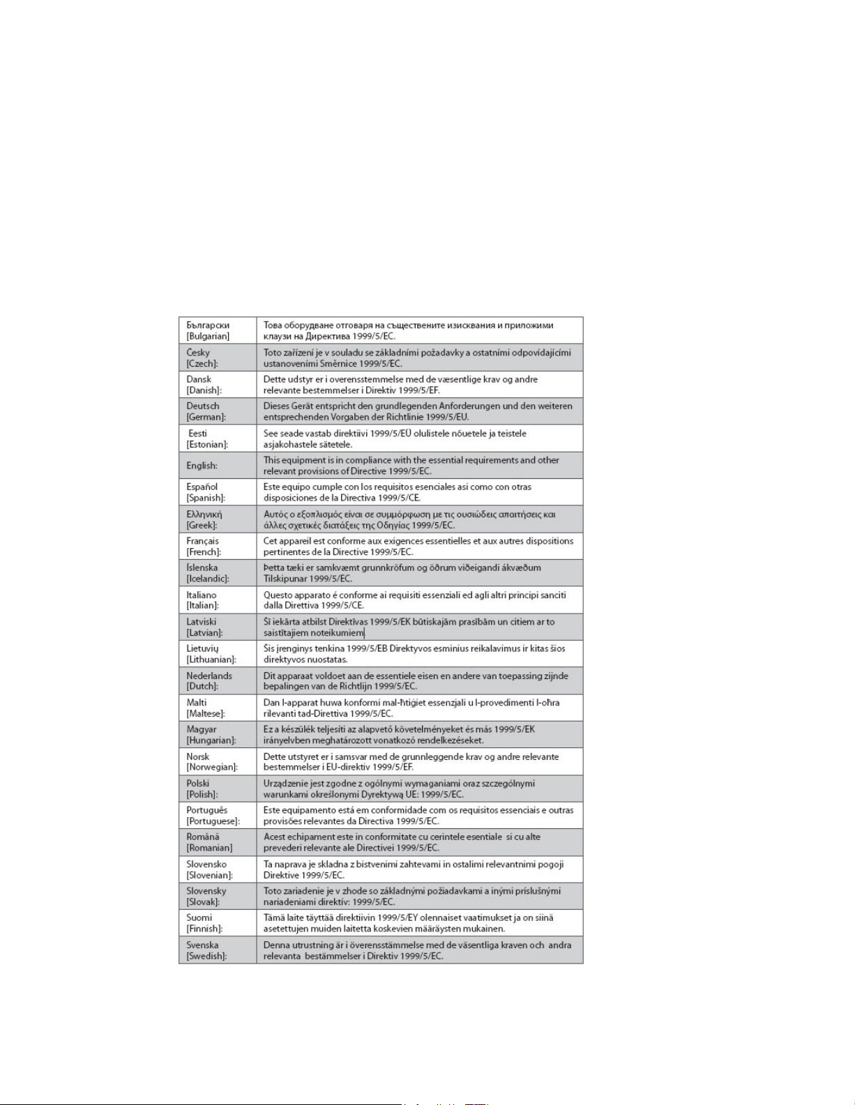
CE Compliance
Declaration of Conformity with Regard to the EU Directive 1999/5/E C (R&TTE Directive)
This declaration is only valid for configurations (combinations of software, firmware and
hardware) supported or provided by Cisco Systems for use within the EU. The use of
software or firmware not supported or provided by Cisco Systems may result in the
equipment no longer being compliant with the regulatory requirements.
Page 12

IMPORTANT SAFETY INSTRUCTIONS
12 4021193 Rev C
Note: The full de claration of conformity for this product can be found in the Declarations of
Conform ity and Regulatory Information section of the appropriate product hardware
installation guide, which is available on Cisco.com.
The following standards were applied during the assessment of the product against the
requirements of the Directive 1999/5/EC:
Radio: EN 300 328
EMC: EN 301 489-1 and EN 301 489-17
Safety: EN 60950 and EN 50385
The CE mark and class-2 identifier are affixed to the product and its packaging. This product
conforms to the following Europe an directives:
-1999/5/EC
National Restrictions
This product is for indoor use on ly.
France
For 2.4 GHz, the output power is restricted to 10 mW EIRP when the product is used
outdoors in the band 2454 - 2483, 5 MHz. There are no restrictions when used in other parts
of the 2.4 GHz band. Check http://www.arcep.fr/ for more details.
Pour la bande 2,4 GHz, la puissance est limitée à 10 mW en p.i.r.e. pour les équipements
utilisés en extérieur dans la bande 2454 - 2483,5 MHz. Il n'y a pas de restrictions pour des
utilisations dans d'autres parties de la bande 2,4 GHz. Consultez http://www.arcep.fr/ pour
de plus amples détails.
Italy
This product meets the National Radio Interface and the requirements specified in the
National Frequency Allocation Table for Italy. Unless this wireless LAN product is operating
within the boundaries of the owner's property, its use requires a “general authorization.”
Please check http://www.comuni cazioni.it/i t/ for more details.
Questo prodotto è conforme alla specifiche di Interfaccia Radio Nazionali e rispetta il Piano
Nazionale di ripartizione delle frequenze in Italia. Se non viene installato all 'interno del
proprio fondo, l'utilizzo di prodotti Wireless LAN richiede una “Autorizzazione Generale”.
Consultare http://www.comuni cazioni.it/i t/ per maggiori dettagli.
Latvia
The outdoor usage of the 2.4 GHz band requires an authorization from the Electronic
Communications Office. Please check http://www.esd.lv for more details.
2,4 GHz frekven?u joslas izmantošanai ?rpus telp?m nepieciešama at?auja no Elektronisko
sakaru direkcijas. Vair?k inform?cijas: http://www.esd.lv.
Note: The regulatory limits for maximum output power are specified in EIRP. The EIRP level
of a device can be calculated by adding the gain of the antenna used (specified in dBi) to the
output power available at the connector (specified in dBm).
Page 13

IMPORTANT SAFETY INSTRUCTIONS
4021193 Rev C 13
Antennas
Use only the antenna supplied with the product.
20090312 CE_Gateway
Page 14

Introduction
Introduction
Welcome to the exciting world of high-speed Internet and high-quality digital
telephone service. Your new Cisco
Residential Gateway with Embedded Digital Voice Adapter is a cable modem that
meets industry standards for high-speed data connectivity along with reliable digital
telephone service. The DPQ3925 residential gateway delivers data, voice and wired
(Ethernet) or wireless gateway capa bilities to connect a variety of devices in the
home or small office and support high-speed data access and cost-effective voice
services, all in one device. With a DPQ3925 residential gateway, your Internet
enjoyment, home and business communications, and p ers onal productivit y will
surely soar.
This guide provides procedures and recommendations for placing, installing,
configuring, opera ting, and troubleshooting your DPQ3925 residential gateway for
high-speed Internet and digital telephone service for your home or office. Refer to
the appropriate section in this guide for the specific information you need for your
situation. Contact your service provider for more information about subscribing to
these services.
Benefits and Features
®
Model DPQ3925 DOCSIS® 3.0 Wireless
Your new DPQ3925 residential gateway offers the following outstanding benefits
and features:
Compliant with DOCSIS 3.0, 2.0, and 1. x st andards along wit h PacketCa ble™
specifications to deliver high-end performance and reliability
High performance broa dband Int ernet connectivit y to energize your online
experience
Two-line embedded digital voice adapter for wired telephony service
Four 1000/100/10BASE-T Ethernet ports to provide wired connectivity
802.11n Wireless Access Point
Ma y inclu de one or two optional internal Lithium-Ion ca rtridge-style batteries
for convenient and long-lasting backup power
Wi-Fi Protected Setup (WPS), including a push button switch to activate WPS for
simplified and secure wireless setup
User configurable Parental Control blocks access to undesirable Internet sites
Advanced firewall technology deters hackers and protects the home network
from una uthorized a ccess
14 OL-30824-01
Page 15

Introduction
Attractive compact design that allows for vertical, horizontal, or wall-mounted
operation
Color-coded interface ports and corresponding cables simplify installation and
setup
DOCSIS-5 compliant LED labeling and behavior provides a user and technician
friendly method to check operational status and act as a troubleshooting tool
Allows automatic software upgrades by your service provider
OL-30824-01 15
Page 16
What's In the Carton?
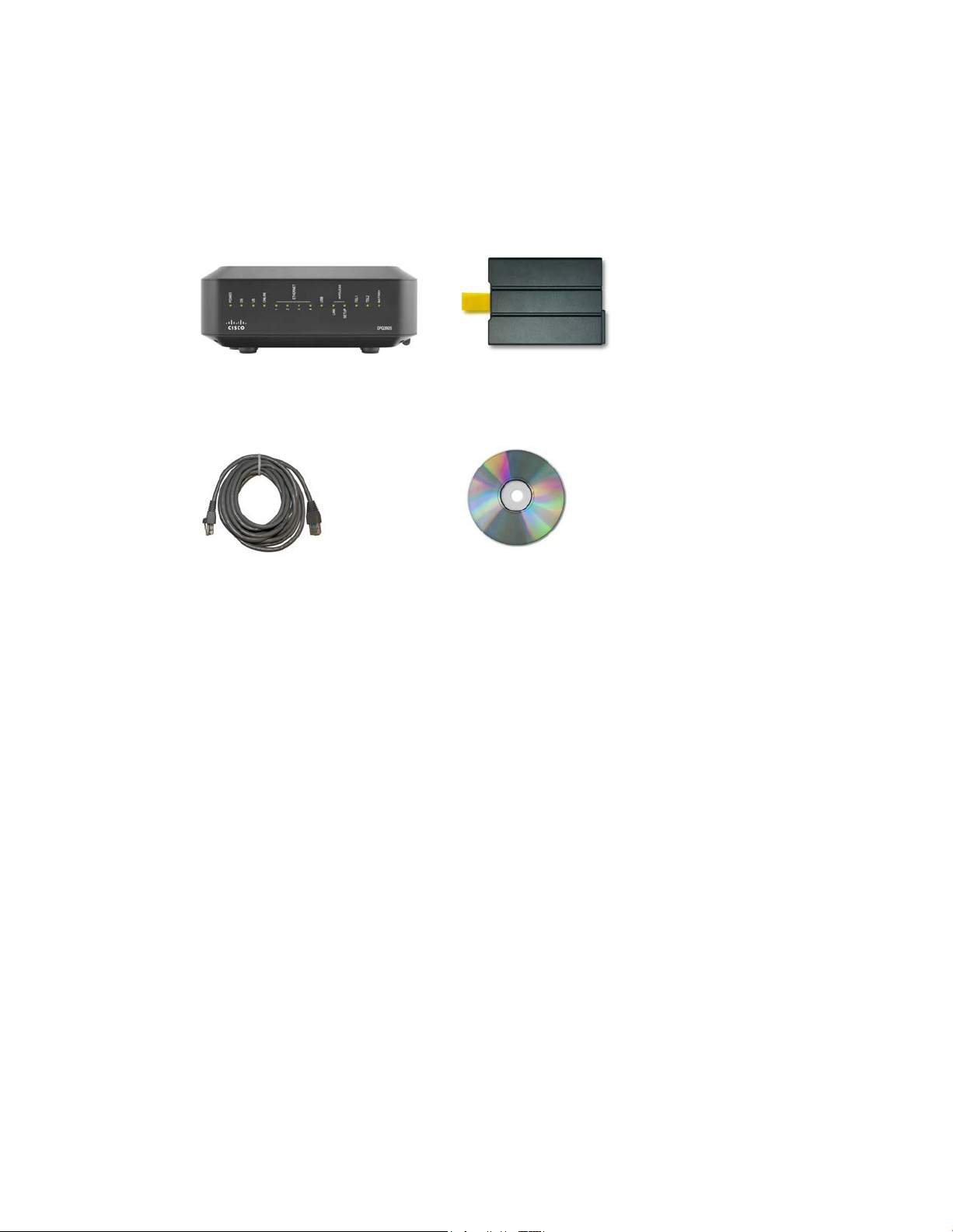
What's In the Carton?
When you receive your wireless residential gateway, you should check the
equipment and accessories to verify that each item is in the ca rt on and that each item
is undama ged. The ca rton cont ains the following items:
One DPQ3925 DOCSIS Residential
Gateway
One Ethernet cable (CAT5/RJ-45)
Lithium Ion cartridg e battery
(optional)
One CD-ROM
If any of these items are missing or damaged, please contact your service provider
for assistance.
Notes:
You will need an optional cable signal splitter and additional standard RF
coaxial cables if you want to connect a VCR, a Digital Home Communications
Terminal (DHCT) or a set-top converter, or a TV to the same cable connection as
your wireless residential gateway.
16 OL-30824-01
Cables and other equipment needed for telephone service must be purchased
separately. Contact your service provider to inquire about the equipment and
cables you need for telephone service.
Page 17
Front Panel Description
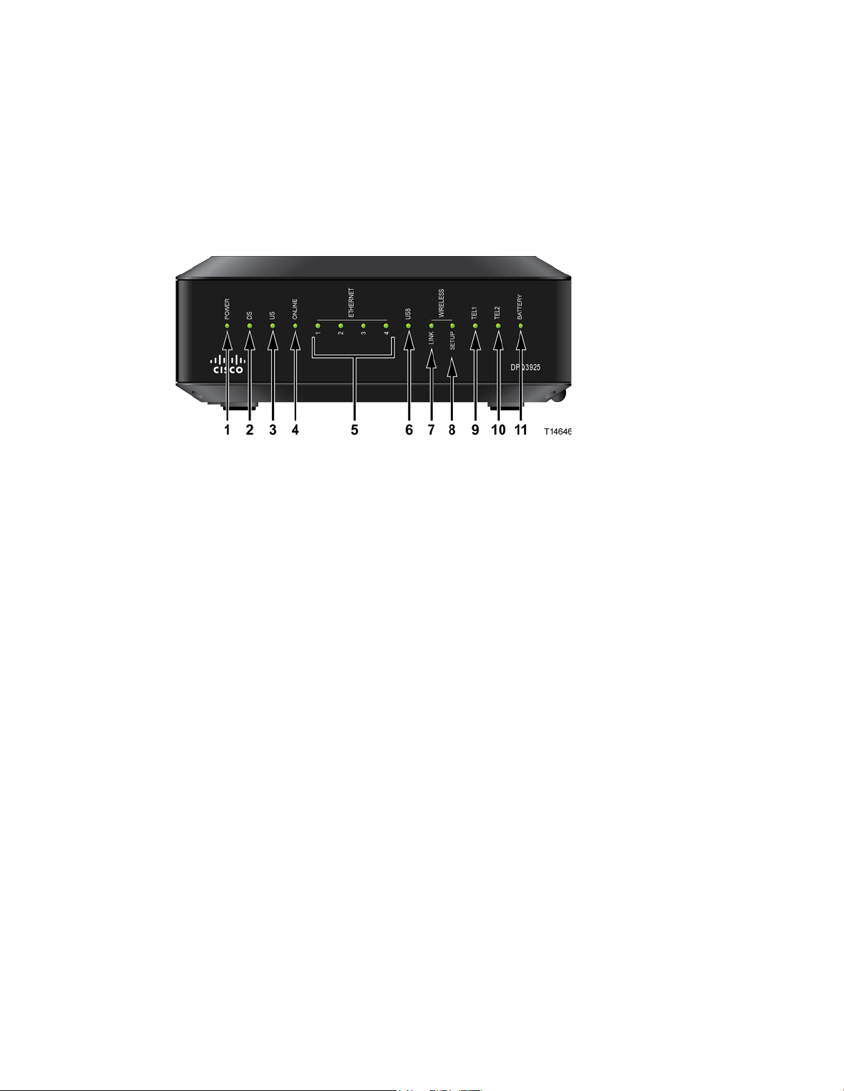
Front Panel Descriptio n
The front panel of your residential gateway provides LED status indicators that
indicate how well and at what state your residential gateway is operating. See Front
Panel LED Status Indicator Functions (on pa ge 102), for more information on front
panel LED sta tus indicat or fu nctions.
Model DPQ3925 sho wn h er e
1 POWER—ON, power is applied to the wireless residential gateway
2 DS—ON, the wireless residential gateway is receiving data from the cable
network
3 US—On, the wireless residential gateway is sending data to the cable network
4 ONLINE—ON, the wireless residentia l gateway is registered on the network and
fully operational
5 ETHERNET 1 - 4—ON, a device is connected to one of the Ethernet ports.
BLINKING indicates that dat a is being transferred over the Ethernet connection
6 USB—ON, a device is connected to the USB port. BLINKING indicates that data is
being transferred over the USB connection
7 WIRELESS LINK—ON, the Wireless Access Point is operational. BLINKING
indicates that data is being transferred over the wireless connection. OFF indicates
that the wireless access point has been disabled by the user
8 WIRELESS SETUP—OFF (normal condition) wireless setup is not active.
BLINKING indicates the user has activated wireless setup to add new wireless
clients on the wireless network
9 TEL1—ON indicates telephony service is enabled. Blinks when line 1 is in use.
OFF indicates t hat phone service for TEL 1 is not enabled
10 TEL2—ON indicates telephony service is enabled. Blinks when line 2 is in use.
OFF indicates t hat phone service for TEL 2 is not enabled
11 BATTERY—If a battery is included, this light illuminates when the battery is fully
cha rged
OL-30824-01 17
Page 18
Back Panel Description
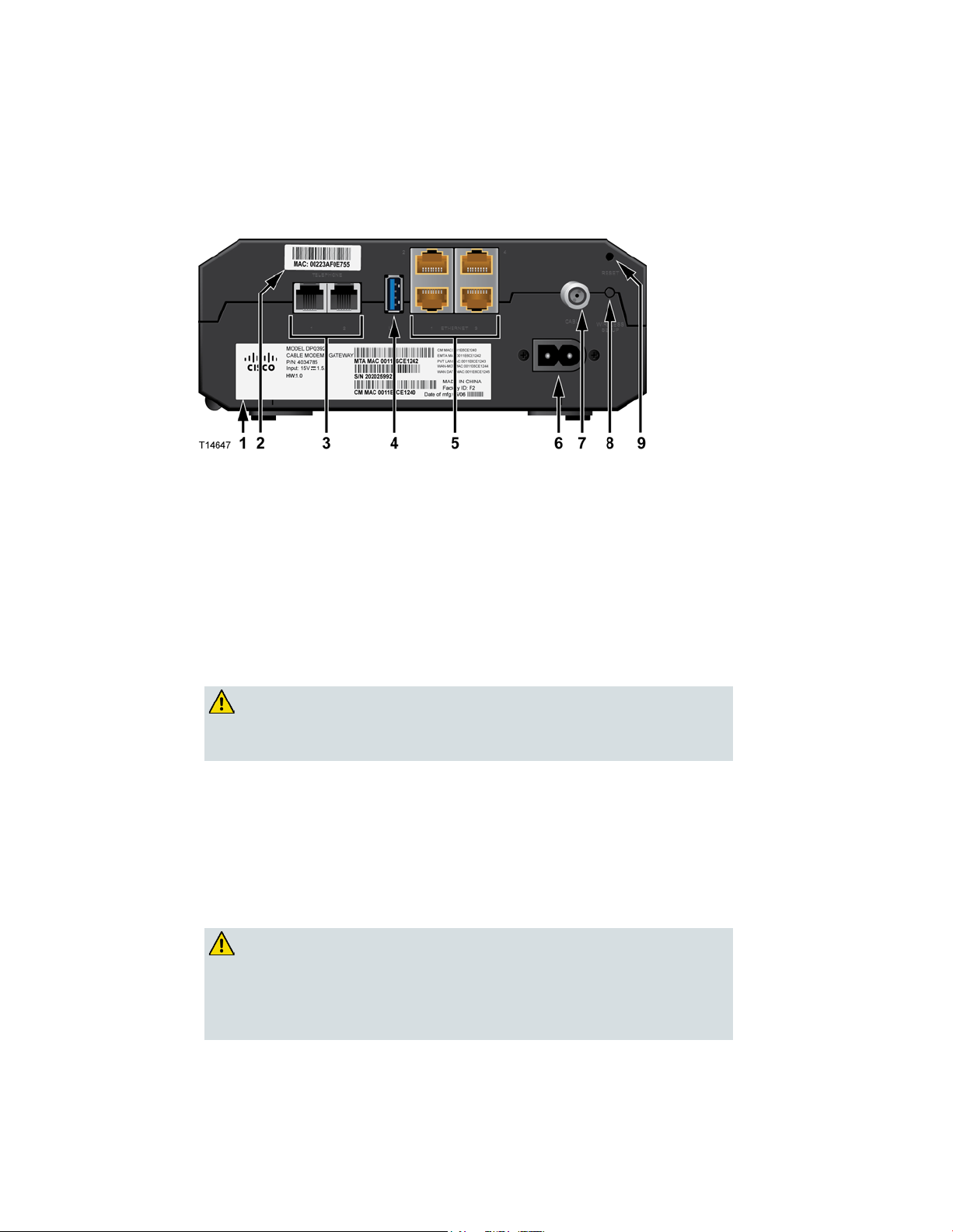
Back Panel D escription
5 Ethernet ports connect to the Ethernet port on your PC or
default of
CAUTION:
The following illust ra tions show the description a nd f unction of the back panel
comp onents on the Cis co DPQ3925 residential gateway.
1 LABEL—Displays technical information regarding the ga teway
2 MAC ADDRESS LABEL—Displays the MAC address of the residential gateway
3 TELEPHONE 1 and 2—RJ-11 telephone p orts connect to home telep hone wiring to
conventiona l telephones or fax machines
4 USB—Connects to selected client devices
5 ETHERNET—Four RJ-4
your home network
6 POWER—Connects the residential gateway to the AC power cord that is provided
with your residential gateway
CAUTION:
Avoid damage to your equipment. Only use the power cord that
is pro vided with your residential gateway .
18 OL-30824-01
7 CABLE—F-connector connects to an a ctive cable signal from your service provider
8 WIRELESS SETUP—Pressing this switch initiates wireless setup, this feature allows
the user to add new Wi-Fi Protected Setup (WPS™) compliant wireless clients to the
home network
9 RESET—A momentary pressing (1-2 seconds) of this switch reboots the EMTA.
Pressing the switch for more than ten seconds first causes a reset-to-factoryall settings and then reboots the gateway
The Reset button is for maintenance purposes only. Do not use
unless instructed to do so by your cable or telephone service
provider. Doing so may cause you to lose any cable modem
settings you have selected.
Page 19

What Are the System Requ irem ents for I n t ernet Service?
What Are the System Requirem ents for Internet Service?
To ensure that your residential gateway operates efficiently for high-speed Internet
service, verify that all of the Internet devices on your system meet or exceed the
following minimum hardware and software requirements.
Note: You will a ls o need an active cable input line and an Internet connect ion.
Minimum System Requirements for a PC
A PC with a Pentium MMX 133 processor or great er
3 2 MB of RAM
Web browsing software
CD-ROM drive
Minimum System Requirements for Macin tosh
MA C OS 7.5 or later
3 2 MB of RAM
System Requirements for an E thernet Connection
A PC with Microsoft Windows 2000 operating system (or later) with TCP/IP
protocol installed, or an Apple Macintosh computer with TCP/IP protocol
installed
An active 10/100/1000BASE-T Ethernet network interface card (NIC) installed
OL-30824-01 19
Page 20
How Do I Subsc r ibe to High-Speed In tern et and Telephone S ervi ce?
How D o I Subscribe to High-Speed Interne t and Telephone
Service?
Before you can use your residential gatewa y, you need to have a high-speed Internet
access a ccount . If you do not have a high-speed Internet a ccess account, you need to
set up an account with your local service provider. Choose one of the options in this
section.
I Do Not Have a High-Sp eed Internet Access Account
If you do not have a high-speed Internet access account, your service provider will
set up your account and become your Internet Service Provider (ISP). Internet access
enables you to send and receive e-mail, access the World Wide Web, and receive
other Internet services.
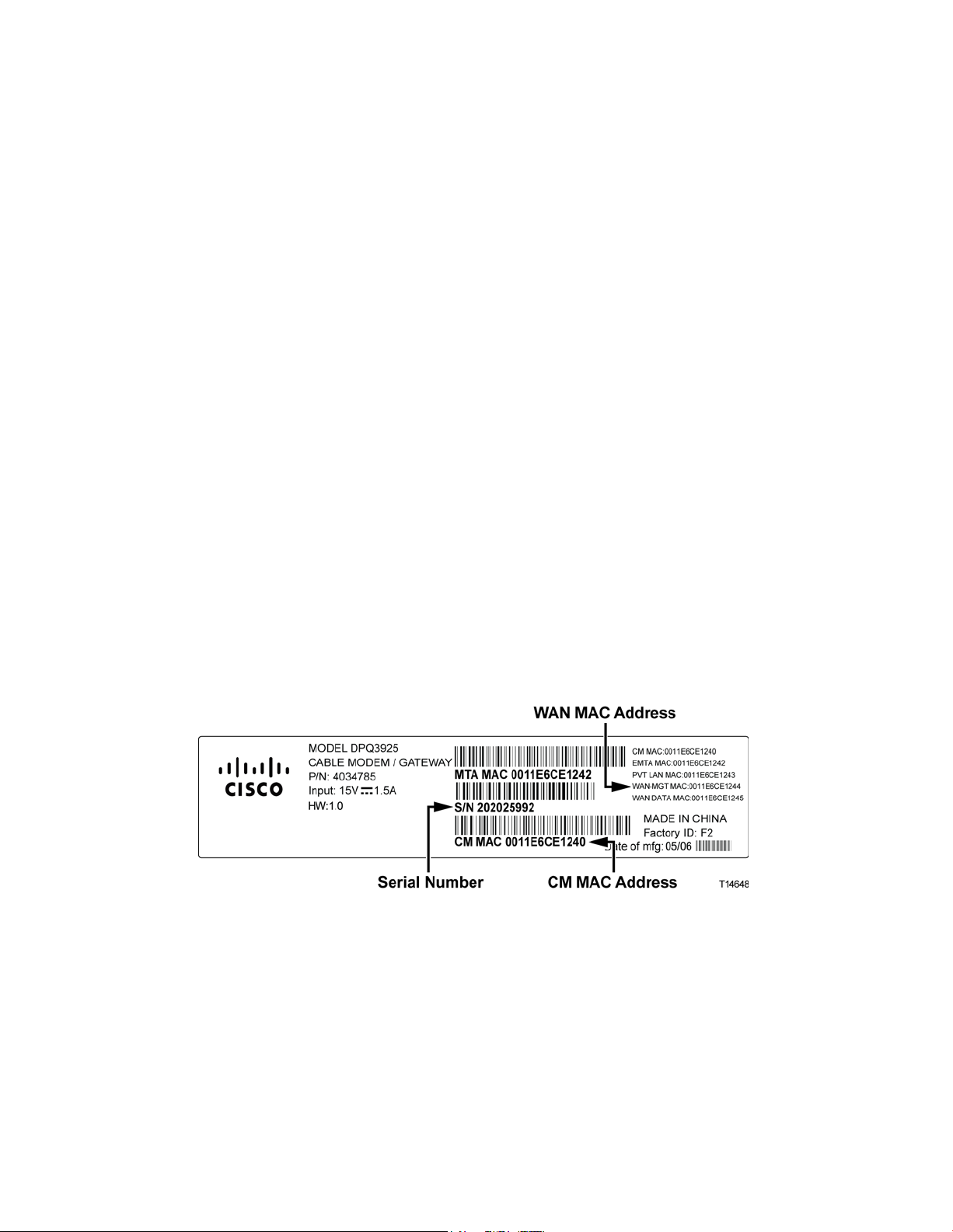
You will need to give your service provider the following information:
The serial number of the modem
The Media Access Control (MAC) address of the modem (CM MAC)
Other MAC address numbers as needed
These numbers a ppear on a bar code la bel located on the residentia l ga teway. The
serial number consists of a series of alphanumeric characters preceded by S/N. The
MAC address consists of a series of alphanumeric characters preceded by CM MAC.
The following illustration shows a sample bar code label.
Write down these numbers in the space provided here.
Serial Number _______________________
MAC Address ________________________
20 OL-30824-01
Page 21

How Do I Subs c r ibe to High-S peed Internet and Telephone Service?
I Already Have an Existing High-Speed Internet Access A ccount
If you have an existing high-speed Internet access account, you must give your
service provider the serial number and the MAC address of the residential gateway.
Refer to the serial number and MAC address information listed previously in this
section.
I Want to Use the Application Server for Tel ephone Service
You will also need to set up a telephone account with your local service provider to
use your residential gateway for telephone service. When you contact your service
provider, you may be able to transfer your existing telephone numbers, or your cable
telephony service provider will assign a new telephone number for each current or
additional active telephone line. Discuss these options with your telephony service
provider.
OL-30824-01 21
Page 22

Where Is the Best Locati on for My D OCSIS R esident ial Gateway?
Where Is the B est Location for My DOCS IS Residential
Gateway?
The ideal location for your residential gateway is where it has access to outlets and
other devices. Think about the layout of your home or office, and consult with your
service provider to select the best location for your residential gateway. Read this
user guide thoroughly before you decide where to place your residential gateway.
Consider these recommendations:
Choose a location close to your computer if you will also use the residential
gateway for high-speed Internet service.
Choose a location tha t is nea r a n existing RF coaxia l connection to eliminate the
need for an additional RF coaxial outlet.
Choose a location for the residential gateway that is adjacent to your telephone
equipment if you are using only one or two pieces of telephone equipment.
Note: If you are using the residential gateway to provide service to several
telephones, a professional installer can connect the residential gatewa y to your
existing home telep hone wiring. To minimize cha nges t o the home telephone
wiring, you may want to locate the residential gateway near an existing
telephone outlet.
Choose a location that is relatively protected from accidental disturbance or
harm, such as a closet, basement, or other protected area.
Choose a location so that there is plenty of room to guide the cables away from
the modem without straining or crimping them.
Airflow around the residential gateway should not be restricted.
Read this user guide thoroughly before installing the residential gateway.
22 OL-30824-01
Page 23
How Do I Mount the M odem on a Wall? (Optional)
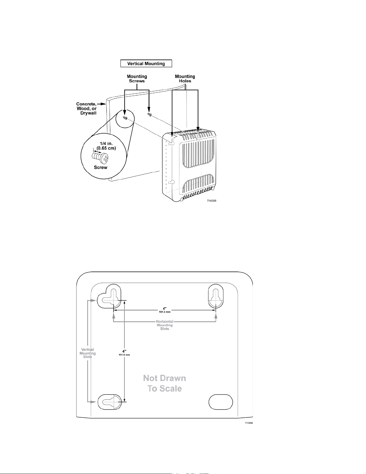
How D o I Mount the Modem on a W all? (O ptional)
You can mount the residential gatewa y on a wall using two wall anchors, two
screws, and the mounting slots located on the unit. The modem can be mounted
vertically or horizontally.
Be fore You Begin
Before you begin, choose an appropriate mounting place. The wall can be made of
cement, wood, or drywall. The mounting location should be free of obstructions on
all sides, and the cables should be able to easily reach the residential ga teway
without strain. Leave sufficient clearance between the bottom of the residentia l
gateway a nd any flooring or shelving undernea t h to a llow a ccess to cabling. In
addition, leave enough slack in all ca bles so that the residential gateway can be
removed for a ny required maintenance without disconnecting the cables . Also,
verify that you have the following items:
Two wall anchors for #8 x 1-inch screws
Two #8 x 1-inch pan head sheet metal screws
Drill with a 3/16-in. wood or masonry bit, as appropriate for the wall
composition
A copy of the wall-mounting illustrations shown on the following pages
Mount the modem a s shown in one of the following illustrations.
OL-30824-01 23
Page 24
How Do I Mount the M odem on a Wall? (Optional)
Locati on and Dim ensions of the Wall-Mounting Slots
The following illustration shows the location and dimensions of the wall-mounting
slots on the bottom of the modem. Use the information on this page as a guide for
mounting your modem to the wall.
24 OL-30824-01
Page 25

How Do I Mount the M odem on a Wall? (Optional)
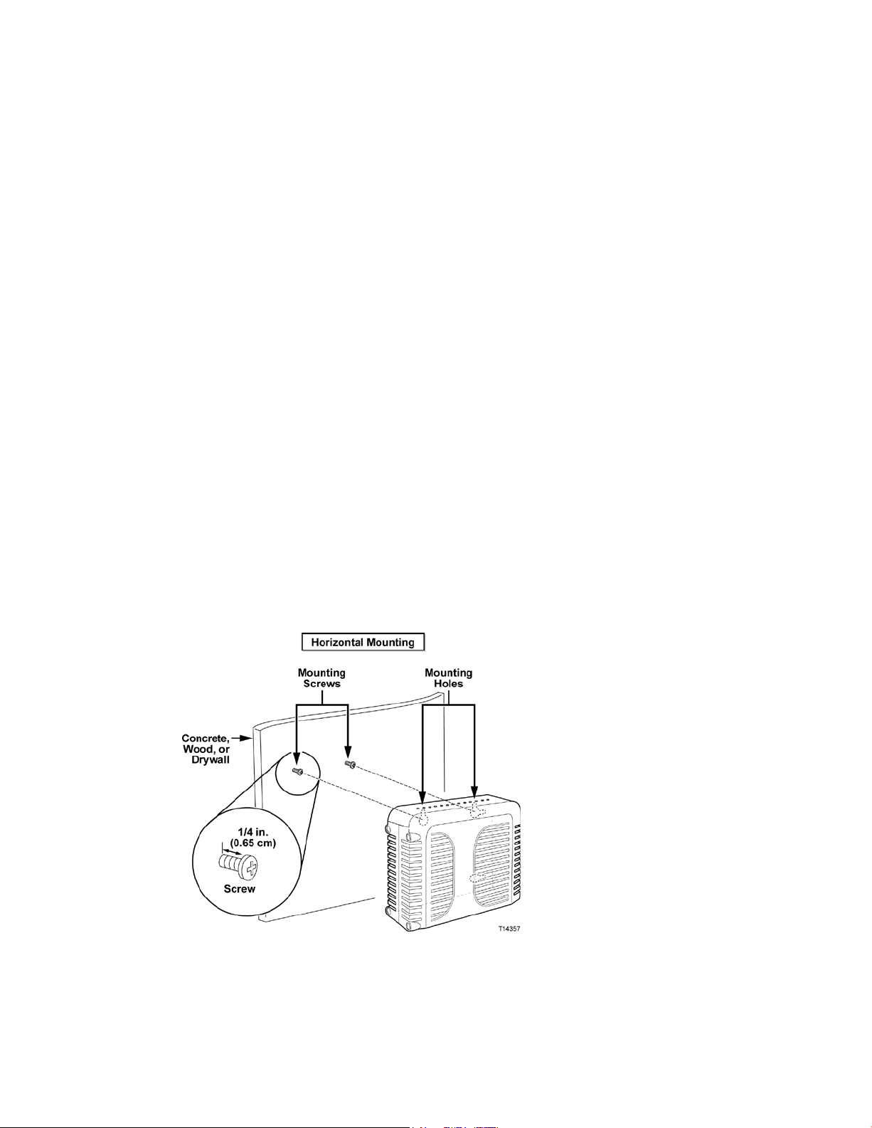
Mounting the Residential Gateway on a Wall
1 Using a drill with a 3/16-inch bit, drill two holes at t he same height and 4 inches
apa rt.
Note: The p receding graphic illustrates the location of the mounting holes on t he
back of the residential gateway.
2 Are you mounting t he residential gateway into a drywall or concrete surface
where a wooden stud is available?
If yes, go to step 3.
If no, drive t he a nchor bolts int o the wall, a nd install the mounting screws
into the anchor bolts; leave a gap of about 1/4-inch between the screw head
and the wall. Then, go to s tep 4.
3 Install the mounting screws into the wall; leave a gap of about 1/4-inch between
the screw head and the wall. Then, go to step 4.
4 Verify that no cables or wires are connected to the residential gateway.
5 Lift the residential gateway into position. Slip the large end of both mounting
slots (located in the back of the residential gateway) over the mounting screws,
and t hen slide the residentia l gateway down until the narrow end of the keyhole
slot contacts the screw shaft.
Important: Verify that the mounting screws securely support the residential
gatewa y before you release the unit.
OL-30824-01 25
Page 26

What Are th e R equi rem ents for Telepho ne Servi ce?
What Are the Requirem ents for Teleph one S ervice?
Num ber of T elephone Devices
The RJ-11 telephone-style connectors on the residential gatewa y can each provide
telephone service to multiple telephones, fax machines, and analog modems.
The maximum number of telephone devices connected to each RJ-11 port is limited
by t he tota l Ringing Load of the telephone devices tha t are connected. Many
telephone devices are marked with a Ringer Equivalent Number (REN). Each
telephone port on the residential gateway can support up to a 5 REN load.
The sum of the REN load on all of the telephone devices attached to each port must
not exceed 5 REN.
Telephone Device Types
You can use telephone devices that are not labeled with a REN number, but the
maximum number of attached telephone devices cannot be accurately calculated.
With telephone devices that are not labeled, each device should be connected and
the ring signal should be tested before adding more devices. If too many telephone
devices are attached and the ring signal can no longer be heard, telephone devices
should be removed until the ring signal works properly.
Telephones, fa x machines, and ot her t elephone devices should use the center 2 pins
of the RJ-11 connectors to connect to the residential gateway telephone ports. Some
telephones use other pins on the RJ-11 connectors a nd require ada pters in order to
work.
Dialing Requirements
All your telephones should be set to use DTMF dialing. Pulse dialing is typically not
enabled by your local provider.
T el ephone W iri ng Requi rem ent s
The residential gateway supports connecting to the interior telephone wiring as well
as connecting directly to a telephone or fax machine. The maximum distance from
the unit to the most distant telephone device must not exceed 1 000 feet (300 meters).
Use 26-gauge twisted-pa ir, or la rger, telephone wiring.
Important: Connection t o an existing or a new perma nent ly installed home
telephone wiring network must be done by a qualified installer.
26 OL-30824-01
Page 27
How Do I Connect M y Gateway for I ntern et and Telepho ne Servi ce?
How Do I Connect My Gateway for Internet and Telephon e Service?
You can use your residential gateway to provide both telephone service and to
provide Internet access, and you can sha re tha t Internet connection with other
Internet devices in your home or of fice. Sharing one connection among many
devices is called networking.
Conne cting a nd Inst all ing Internet D evi ces
Professional installation may be available. Contact your local service provider for
further assistance.
To con n ect d evi ces
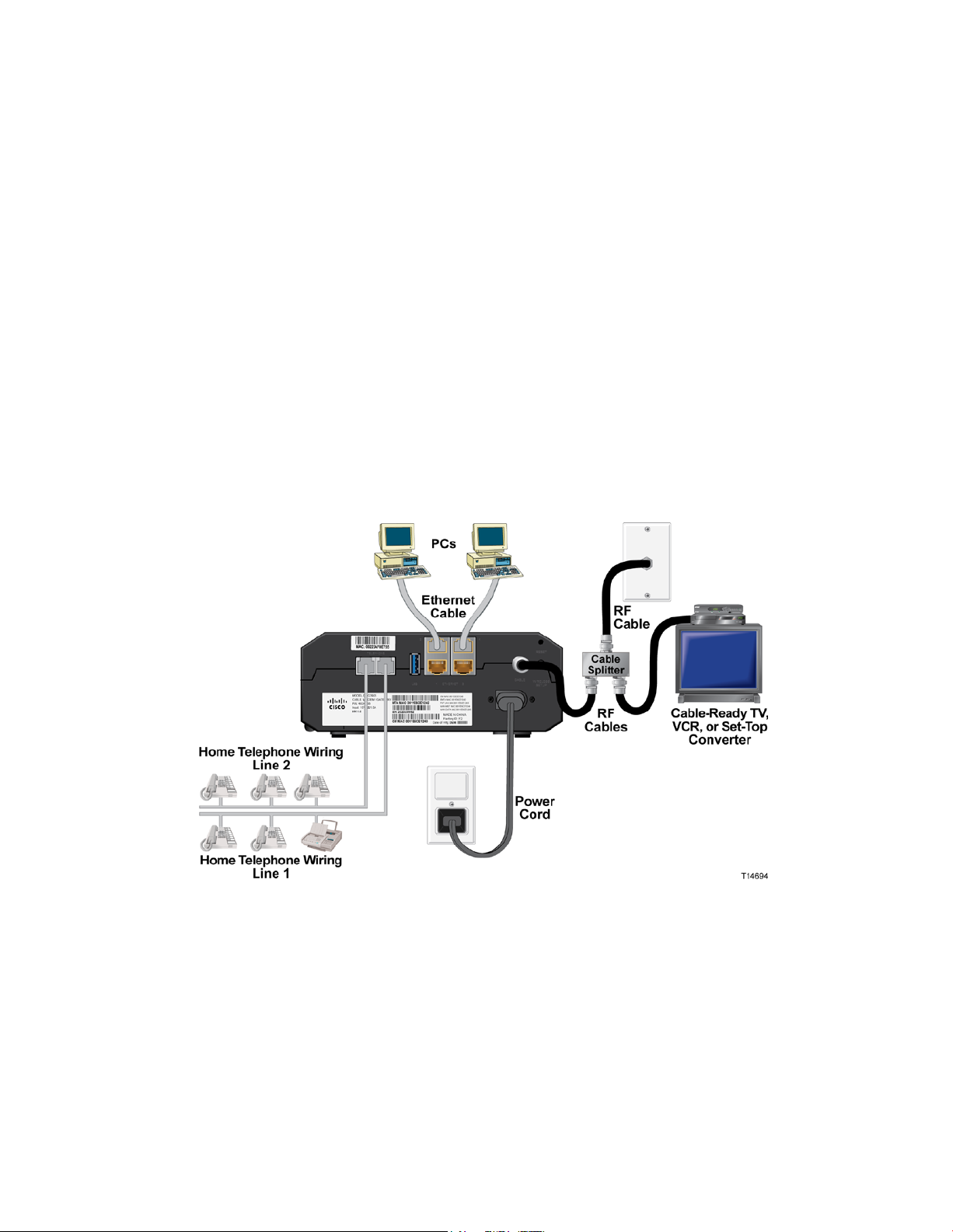
The following diagram illustrates one of the various networking options that are
available to you.
Conne cting t he Residential Gateway for H igh-Speed Data and T elephone Service
The following installation procedure ensures proper setup and configuration for the
residential ga teway.
1 Choose an appropriate and safe location to install the residential gateway (close
to a power source, an active cable connection, your PC—if using high-speed
Internet, and your telephone lines—if using VoIP).
OL-30824-01 27
Page 28

How Do I Co nnect My Gateway for Internet and Telephone Servi ce?
WARNING:
To avoid personal injury, follow the installation instructions in the exact
order shown.
To prevent possible damage to equipment, disconnect any other telephone
service before connecting your cable modem to the same wires.
Hazardous electrical voltages can exist on the telephone ports on the
residential gateway and can be present on any connected wiring including
Ethernet wiring, telepho ne wiring and coax cable.
Telephone wiring and connections must be properly insulated to prevent
electrical sho ck.
Telephone connections to an installed home telephone wiring network
must be done by a qualified installer. The cable telephone service
pro vider may offer pro fessional installation and connection to the home
telephone wiring network. A fee may be charged for this service.
Wiring and connections must be properly insulated to prev ent electrical
shock.
Disconnect power from the residential gateway before attempting to
connect to any device.
2 Power off your PC and other networking device; then, unplug them from the
power source.
3 Connect the active RF coaxial cable from your service provider to the coax
connector la beled CABLE on the back of the residential gateway.
Note: To connect a TV, DHCT, set-top, or VCR from the same cable connection,
you will need to install a cable signal splitter (not included). Always check with
your service provider before using a splitter as a splitter may degrade the signal.
4 Connect your PC to t he residentia l gateway using eit her of the following
methods.
Ethernet Connection: Locate the yellow Ethernet cable, connect one end of
the Et hernet cable to the Et hernet port on your PC, a nd connect the other end
to the yellow ETHERNET port on the back of the residential gateway.
Note: To install more Ethernet devices than ports provided on the residential
gatewa y, use an external multi-port Ethernet switch(s).
Wireless: Make sure that your wireless device is powered up. You will need
to associate your wireless device with the wireless gateway once the gatewa y
is operational. Follow the directions provided with your wireless device for
associating with a wireless access point.
More information about the factory default configuration of your wireless
gateway can be found later in this user guide in Configure Wireless Settings
(on page 41).
28 OL-30824-01
Page 29

How Do I Connect M y Gateway for I ntern et and Telepho ne Servi ce?
5 Connect one end of a telephone jumper cable (not included) to a telephone outlet
in your home or to a telephone or fax machine. Then connect the other end of the
jumper cable to the appropria te RJ-11 TELEPHONE port on the back of the
residential ga teway. The telephone ports are light gray and a re labeled 1/2 and 2
or 1 and 2 depending on the region of the world the residential gateway is used.
Notes:
– Make sure to connect your telephone service to the correct RJ-11 port. For
single line telephone service, connect to port 1/2 or 1.
– In North America, residential gateways have multi-line capability on the
RJ-11 telephone port labeled 1/2. Line 1 is on pins 3 and 4 of port 1/2,
and Line 2 is supported on pins 2 and 5. In Europe, residential gatewa ys
support only one line per port . Line 1 is on port 1 and line 2 is on port 2.
– Telephones that require electrical connectors other than RJ-11 may
require an external a dap ter (sold separat ely).
6 Locate the AC power cord provided with your residential ga teway. Insert one
end of the power cord into the AC connector on the back of the residentia l
gatewa y. Then, plug the AC power cord into an AC outlet to power-up the
residential gateway. The residential gateway will perform an automatic search to
locate a nd sign on to the broadband data network. This process may take up to 25 minutes. The modem will be ready for use when the POWER, DS, US and
ONLINE LEDs on the front pa nel of the res idential gateway stop blinking and
rema in on continuously.
7 Plug in and power on your PC and ot her home network devices. The LINK LED
on the residential gateway corresponding to the connected devices should be on
or blinking.
8 Once the residential gateway is online, most Internet devices will have
immediate Internet access.
Note: If your PC does not have Internet access, refer to Frequently Asked
Questions (on p age 97) for information on how to configure your PC for TCP/IP.
For Internet devices other than PCs, refer to the DHCP or IP Address
configuration section of the User Guide or Operations Manua l for those devices.
OL-30824-01 29
Page 30

How Do I Maintain the Batte r y ? ( Optional)
How Do I Maintain the Battery? (Optional)
WARNING:
Your modem may include a rechargeable Lithium-Ion battery to provide stand-by
operation in the event of an AC power failure. You ca n replace the battery without
the use of any tools.
Fully charged high-capacity rechargeable batteries should be handled with
care. Replace only with the battery recommended by the manufacturer. Do not
disassemble it or attempt to recharg e the battery outside the system. Do no t
crush, puncture, dispose of in a fire, short the external contacts, or expose to
high temperature or immerse in water or other liquids. Dispose of the battery
in accordance with lo cal regulatio ns and instructions from your service
provider.
Cha rging the B att ery
The battery begins to charge automatically as soon as you attach the modem to the
AC electrica l outlet. When you first plug in the modem, the POWER LED status
indicator illuminates.
Important: It may take as long as 24 hours for the battery to charge fully.
Us ing the Modem W ithout a Batt ery
If you want, you can use the modem without a battery. If you need to remove the
battery, follow the procedures found in Removing and Replacing the Battery
(on page 31).
Important: If you choose to operate your modem without a battery, you risk losing
your telephone service during a power outage.
Replacing the Battery
Under normal circumsta nces, the battery should last for several years. The
BATTERY LED status indicator turns off to indicate that the battery should be
repla ced soon. Contact your service provider to obtain replacement batteries and for
disposal instructions.
Note: Follow the steps found in Removing and Replacing the Battery (on page 31) to
remove and replace the battery.
30 OL-30824-01
Page 31
How Do I Maintain the Batte r y ? ( Optional)
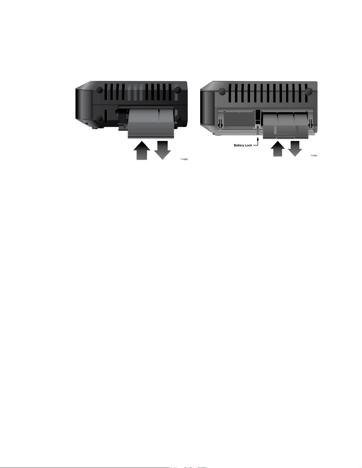
Loca t ion of Ba t t e ry
As shown in the following illustrations, the battery compartment is located on the
right side panel for both DPQ3925 hou sing t ypes .
Housing Type 1
Housing Type 2
Bef ore Re moving a nd Re pla c ing th e Battery
Before removing and replacing the battery, refer to the following important
information.
You can remove and replace the battery without disconnecting the AC power
source.
It may take as long as 24 hours for each battery to charge fully.
Dispose of the battery in accordance with local regulations and inst ructions from
your service provider.
Removing a nd Re pla c ing t he B a tt e ry , Ho us ing Type 1
1 Open the battery door by operating the battery door lock on the side of the unit.
2 Grasp the plastic pull-tab on the battery and gently slide the battery forward to
remove it from the battery compartment.
3 Insert a new battery into the battery compartment.
4 Close the battery compartment door.
Removing a nd Re pla c ing t he B a tt e ry , Ho us ing Type 2
1 Open the battery door by pressing on t he batt ery door where indicat ed on the
side of the unit.
2 Slide the gray battery lock release inside the battery compartment upward to
disengage the battery lock.
3 Grasp the plastic pull-tab on the battery and gently slide the battery forward to
remove it from the battery compartment.
4 Insert a new battery into the battery compartment.
5 Close the battery compartment door. The battery lock will automatically engage.
OL-30824-01 31
Page 32

How Do I Configur e My DOCSIS Residential Gateway?
How Do I Configure My DO CS IS Residential Gateway?
To configure your residential gateway, you must first access the WebWizard
configuration pages. This section provides detailed instructions and procedures for
accessing the WebWizard pa ges and for configuring your residential gateway to
operate correctly. This section also presents examples and descriptions of each
WebWizard configuration page. Use the WebWizard pages to customize your
residential ga teway to your needs rather than using the default settings. The
WebWizard pages in t his section are organized in the order shown on the Setup
pa ge.
Important: The WebWiza rd pages and the examples shown in this section are for
illustration purposes only. Your pages may differ from the pages shown in this
guide. The pages shown in this guide also represent the default values for the
device.
Note: If you are not familiar with the network configuration procedures detailed in
this section, contact your service provider before you attempt to change any of the
residential gateway default settings.
Logging i n to the G atew ay for the First Ti m e
The default configuration of the gateway uses IP address 192.168.0.1. If you have
connected the gateway correctly and you have properly configured your computer,
use the following steps to log in to the gateway as an administrator.
1 On your PC, open the web browser that you prefer to use.
32 OL-30824-01
Page 33

How Do I Configur e My DOCSIS Residential Gateway?
2 In the address field, enter the following IP address: 192.168.0.1. A Status DOCSIS
WAN login page similar to the following page opens.
3 On the Status D OCSIS WAN page, leave the User Name and Password field
blank and click Log In. The gateway opens with an Administration Management
page in the forefront. You can use the Administ ra tion Management pa ge to
cha nge your User Name and Pa ssword.
At this point you are logged into the gateway. You can select any of the setup
and management web pages. However, you were directed to the Administration
Management to serve as a reminder to set up a new password.
Important: We highly recommend that you set up a new password to safeguard
against the possibility of Internet attacks that look for devices operating with
well-known or factory default user names and/or passwords.
OL-30824-01 33
Page 34

How Do I Configur e My DOCSIS Residential Gateway?
4 On the Administration Management page, crea t e a User Na me and Pa ssword
and t hen click Save Settings. Once you save the settings for your User Name and
Pas sword on the Administration Management page, the Setup Quick Setup page
opens.
Important: You have the option to leave the password field blank (fa ctory
default). However, if you do not change your User Name and Password, you
will be directed to the Administrative Management page each time you access
the ga teway. This serves as a reminder to set up your personalized password.
Once you have personalized your Password, subsequent logins will take you
directly to the Setup Quick Setup pa ge.
5 After you make your selections, click Save Settings to apply your changes or
Cancel Changes to cancel.
Setup > Quick Setup
The Setup Quick Setup page is the first page to open after you have logged on to
you r gateway. You ca n use the settings on this page to change your pa ssword and to
configure the WLAN.
Important: The settings on this page are unique to your device. If you choose, you
do not need to make a ny changes to the settings on t his page. These default settings
are a ll that you need to operate a secure wireless network.
34 OL-30824-01
Page 35

How Do I Configur e My DOCSIS Residential Gateway?
Change Password
User Name
Configuring Quick S e t t ings
Use the descriptions and inst ructions in the following ta ble to configu re t he network
settings for the device. After you make your selections, click Save Settings to apply
your changes or click Cancel Changes to cancel.
Section Field Description
Displays the user name for the operator currently logged in
Change Password to
Allows you to chang e your password
Re-Enter New Password
Allows you to re-enter the new password. You must enter the same
password as the one entered in the field Change Password to
OL-30824-01 35
Page 36

How Do I Configur e My DOCSIS Residential Gateway?
Section Field Description
Allows you to select a wireless security mode to help protect your
WLAN Wireless Network
Allows you to enable or disable the wireless network. Select the
desired option:
Enable
Disable
Wireless Netwo rk Name (SSID)
Allows you to enter a name for your wireless network or to use the
default value. The value you enter he will be viewable on PCs and
other wireless client devices such as the wireless network name.
Note: The factory default Service Set Identifier (SSID) is normally
equal to the last 6 characters of the CM MAC Address. The CM MAC
Address can be found on the rating label attached to your wireless
gateway.
Wireless Security Mode
network. If you select Disable then your wireless network is not
secure and any wireless device within range may connect to it. See
Wireless Security (on page 45) for detailed descriptions of wireless
security modes.
Note: The factory default Wireless Security Mode is WPA or
WPA2-Personal.
Encryption
Allows you to select a level of encryption based on the wireless
security mode you choose. See Wireless S ecurity (on pag e 45) for
detailed descriptions of encryption.
Pre-Shared Key
The pre-shared key for the device. The key can be from 8 to 63
characters. The factory default Pre-Shared Key is equal to the 9-digit
serial number of your gateway. The serial number can be found on
the rating lab el attached to your wireless gateway.
Note: Y our service pro vider may provide you with a wireless
config uration card that contains SSID and wireless security
configuration information for your home network that may differ
from what is described above.
36 OL-30824-01
Page 37
How Do I Configur e My DOCSIS Residential Gateway?
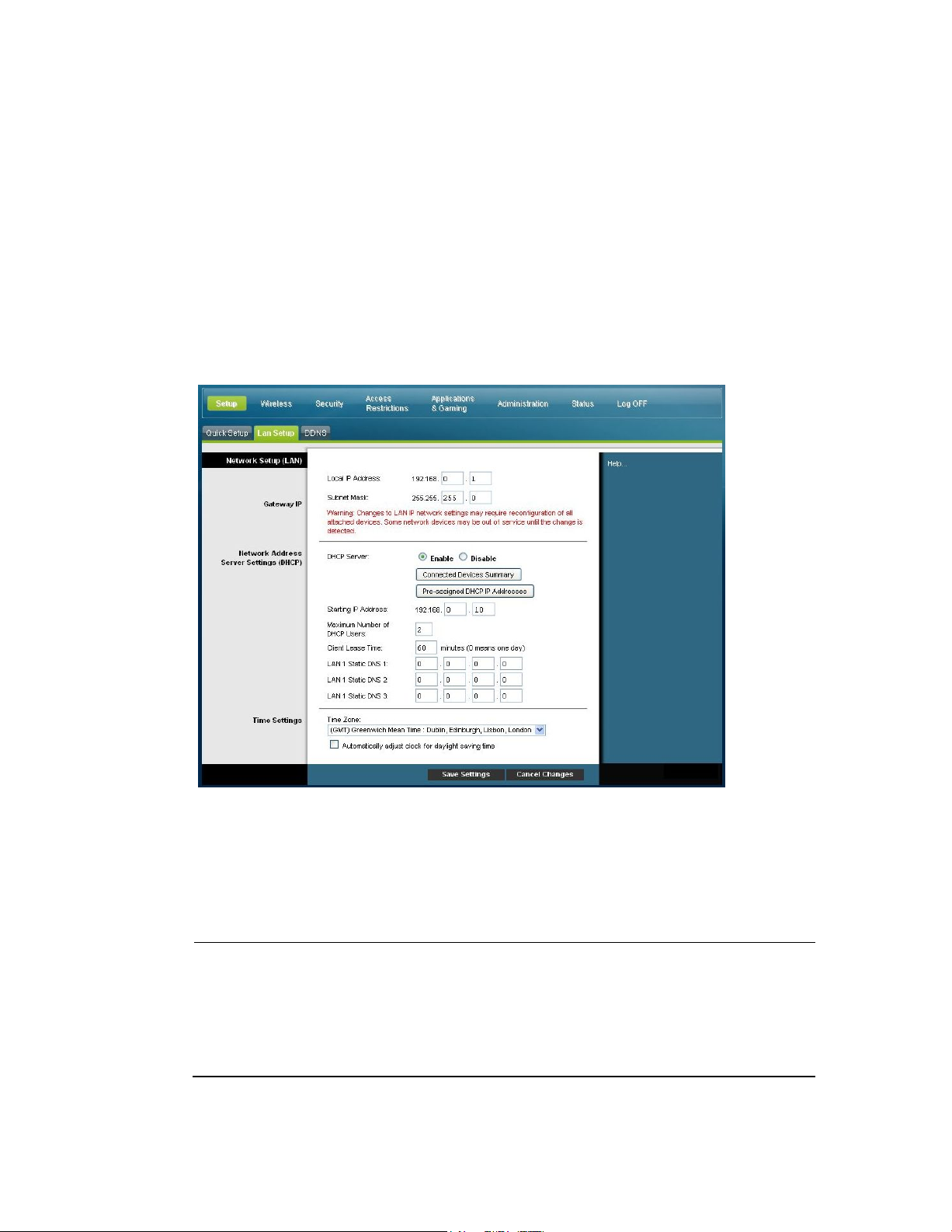
S etup > Lan S etup
Section
Field Description
The Setup Lan Setup page allows you to configure the settings for the Local Area
Network (LAN) in your home. These settings include the range of IP addresses that
define the LAN itself as well as how the addresses are assigned (automatically by
DHCP or manually) as new devices are added to the network.
Important: Unless you are knowledgeable about administering IP addresses, we
recommend that you do not cha nge these sett ings. If you change these values
incorrectly, you can lose Internet access.
Select the Lan Setup tab to open the Setup Lan Setup page.
Configuring Y our Ne t w ork S e t t ings
Use the descrip tions and instructions in the f ollowing table to configu re t he network
settings for your residential gateway. After you make your selections, click S a ve
Settings to apply your changes or click Cancel Changes to cancel.
Network Setup
(LAN)
Gateway IP
OL-30824-01 37
Local IP Address
The base IP address of the private home LAN. The factory default
LAN IP Address is 192.168.0.1.
Subnet Mask
The subnet mask for y our LAN
Page 38

How Do I Configur e My DOCSIS Residential Gateway?
Section Field Description
allocate IP addresses to devices as they are attached to your home
distribute Private LAN IP addresses. Because the device default
Network Address
Server Settings
(DHCP)
DHCP Server
Allows you to enable or disable the DHCP server in the
residential gateway. The DHCP server is used to automatically
ne twork.
Connected Devices Summary page
Click Connected Devices Summary in the Lan Setup page. The
Connected Devices Summary page opens. This page is a pop-up
window that displays the MAC Address and IP Address of the
devices that are connected to the residential gateway.
Pre-assigned DHCP IP Addresses page
Click Pre-assigned DHCP IP Addresses in the Lan Setup page.
The Pre-assigned DHCP IP Addresses page opens. This page
allows you to assign a specific IP address to a PC or other device
when they request an IP address using DHCP. Only addresses
within the range of the gateway's DHCP address pool can be
reserved with this feature.
Notes:
– The Add Static IP button adds the Static IP address to the
list of pre-assigned IP addresses.
– The Remove Static IP b utton removes the Static IP
address from the list of pre-assigned IP addresses
Starting IP Address
Display s the starting address used by the built-in DHCP server to
IP address of the gateway is 192.168.0.1, the starting IP address
must b e 192.168.0.2 or greater, but smaller than 192.168.0.253. The
default Starting IP Address is 192.168.0.10.
38 OL-30824-01
Page 39

How Do I Configur e My DOCSIS Residential Gateway?
Section Field Description
and other devices that use DHCP to obtain IP addresses. If a lease
pire, the IP address will be returned to the pool of
website. You can manually specify which DNS servers are to be
these fields. Otherwise, the gateway will forward
Maximum Number of DHCP Users
Enter the maximum number of users to which the DHCP server
can assign IP addresses for use in the LAN. This number cannot
be greater than 254 minus the starting IP address described
ab ove.
Client Lease Time
The Client Lease Time is the amount of time an IP address is
valid. IP address leases are renewed automatically by your PC
is allowed to ex
available IP addresses that can be assigned by the DHCP server
as new devices are added to your network. The default is 60
minutes when the gateway is online.
LAN Static DNS (Domain Name Server) 1-3
DNS is used by a PC or other client devices to discover the public
IP address associated with a URL or the name-based address of a
used by devices in your network by entered the IP addresses of
those servers in
the DNCS server information from your service provider
automatically. The default is to leave these fields blank.
Time Settings Time Zone
Select the time zone for your location. If your location follows
daylight saving time, select Auto matically adjust clock for
day light saving time.
Setup > DDNS
Dynamic Domain Name Service (D DNS) provides the residential ga teway (that may
have a cha nging IP address) with a host name or URL resolva ble by network
app lications through st andard D NS queries. DDNS is useful when you are hosting
your own website, FTP server, or other server behind the device. Before using this
feature, you need to sign up for DDNS service.
Select the DDNS tab to open the Setup DD NS pa ge.
OL-30824-01 39
Page 40

How Do I Configur e My DOCSIS Residential Gateway?
DDNS
Enabling DDNS
Section Field Description
Disabling DDNS (F actory Default Settings)
Service
To disable DDNS, select Disabled from the drop-down list and click Save
Settings.
Note: In order to use the DDNS feature, you must first set up an account and
establish a URL with www.Dy nDNS. org. The DDNS feature will not work
without a valid account.
To set up a DDNS account, open y our browser an d e nter www.D y nDNS.org
in the address bar. F ollow the instructions on the website to set up an account.
To enable DDNS, follow these steps.
1 On the DDNS page, select www. DynDNS. org as your DDNS server.
2 Configure the following fields:
User Name
Password
Host Name
3 Click Save Settings. The device will now advise the DDNS service of your
current WAN (Internet) IP address whenever this address changes.
Important: The Status area of the window will display the status of the
DDNS service connection.
40 OL-30824-01
Page 41

Configure Wireless S ettings
Configure W ireless Settings
This section describes the options available from the Wireless pages that you can use
to configure the parameters of the WAP to meet your specific requirements a nd
needs.
Wireless > Basic Sett ings
Setting up your residential gateway for wireless communication provides you with
the freedom to connect to the Int ernet from any locat ion wit hin range of the WA P
withou t having to use wired connections. Select the Basic Settings tab to op en the
Wireless Basic Settings page.
The Wireless Basic Settings page allows you to choose your wireless network mode
and other basic features.
Wireless Network: Enable or Disable
Wireless Configuration: Manual or Wi-Fi Protected Setup (WPS)
Network Mode
Radio Band
Channel Widt h
Standa rd Channel
Wireless Network Name (SSID)
Wi-Fi Protected Setup (WPS)
When you select Wi-Fi Protected Setup (WPS) as your wireless configura tion, many
settings will be pre-configured. WPS allows simplified setup that allows you to
easily attach new WPA-enabled devices to your network.
Important: When using WPS mode, WEP is not supported. If you must use WEP
encryption, WPS mu st be disabled by setting the Wireless Configuration to Manual.
Note: WPS is the default setting.
OL-30824-01 41
Page 42

Configure Wi rel ess Settings
Wirele s s Conf igura t ion Wi-Fi Protected Setup Example
Wirele s s Conf igura t ion Wi-Fi P rot e c t e d S e t up Page Des c ript ion
Use the descriptions and inst ructions in the following table to configure the basic
settings for Wi-Fi Protected Setup for the residential gateway. After you make your
selections, click Save Settings to apply your changes or
Section Field Description
Basic Setting s
Enable or Disable the wireless network
Wi-Fi Protected Setup Configuration
The Wi-Fi Protected Setup feature automatically configures an
en cryption-secured, wireless network. To use Wi-Fi Protected Setup, you
must have at least one other device that supports Wi-Fi Protected Setup
in your ne twork. After you hav e config ured your Wi-Fi Protected Setup
devices, you can manually configure other devices.
WPS Push Button Setup (Option 1)
Press the Wi-Fi Protected Setup button on the Basic Wireless Settings
page or the button on the back panel of the gateway to register a wireless
client with the gateway . Press the Wi-Fi Protected Setup software button
on the client side at the same time as the Wi-Fi Protected Setup button is
pushed on the gateway. The connection will be automatically set up.
Cancel Changes to cancel.
42 OL-30824-01
Page 43

Configure Wireless S ettings
Section Field Description
WPS Setup Using Your Wi-Fi Adapter PIN (Option 2)
This is the most secure option to register a wireless client with the
gateway. You need the Wi-Fi Protected Setup PIN number, which is
found in the client Wi-F i Protected Setup utility. After entering the client's
Wi-Fi Protected Setup PIN number, you can then connect to the g ateway.
WPS Setup Using the Gateway PIN (Option 3)
Note the gateway's Wi-Fi Protected Setup PIN number that is displayed
on the Wi-Fi Protected Setup page. Click the Register b utton in Option 3,
then using any Wi-Fi Protected Setup client utility or Microsoft Vista,
enter the gateway's Wi-Fi Protected Setup PIN number into the client
device to complete reg istration.
Wireless Configuration Manual Page Example
Wi r el ess Basic Setti n g s Pag e D escr i p ti o n
Use the descriptions and inst ructions in the following table to manually configure
the basic settings for wireless communication for the residential gateway. After you
make your selections, click Save Settings to apply your changes or
Cancel Changes
to cancel.
OL-30824-01 43
Page 44

Configure Wi rel ess Settings
Section Field Description
Radio Band
Standard Channel
network settings. All devices in your wireless network must broadcast on the
Basic Setting s Wireless Network
Enable or Disable the wireless network
Wireless Configuratio n
The default is WPS. See Wi-Fi Protected Setup (WPS) (on page 41) for more
information about using WPS.
Select Manual to manually set up your network using this option.
Network Mode
Choose one of these options for the ne twork mode:
G only, B /G Mixed, B /G/N Mixed (factory default)
Important: When TKIP authentication only is selected, B/G/N Mixed network
mode is not available.
Select Enabled 2.4GHz (factory default) or Enabled 5GHz
Note: The 5G Hz radio band may not be supported on some models.
Channel Width
Choose Standard - 20 MHz Channel or Wide 40 MHz Channel
Select one of the channels from the drop-down list to correspond with your
same channel in order to communicate. You can select Auto (factory default) for
automatic channel selection.
44 OL-30824-01
Page 45

Configure Wireless S ettings
Section Field Description
technology to identify your network from other wireless networks in the area.
Wireless Netwo rk Name (SSID)
The SSID is the name of your wireless network. The SSID is used by wireless
The SSID can be up to 32 characters long. The factory default SSID is typically
the last 6 characters of the CM MAC address found on the rating label located
on the bottom of your gate way.
This SSID is a unique identity and does not need to be changed unless you
choose to do so. Your service provide r may provide you with wireless setup
information that may call for a different SSID.
BSSID
Display s the Basic Service Set Identifier (BSSID) of your wireless network. The
BSSID is typically the MAC Address of the wireless access point.
Note: This may not be the same MAC Address as the CM MAC Address used
to determine the factory default SSID.
Broadcast SSID
When this box is checked (factory default), the gateway transmits or advertises
its presence to other wireless devices. Client devices can automatically detect
the access point when this beacon is enabled.
Un check this box if you want to hide your network from wireless clients. If you
hide your network, you will need to configure each of your wireless client
devices manually.
Important: The Enable check b ox is not currently in use and does not impact
operation of the gate way.
Wireless > Wireless Security
Selecting a wireless security mode helps protect your network. If you select Disable,
then your wireless network is not secure and any wireless device within range may
connect to it.
To keep intruders out of your wireless network, use the Wireless Security page to
configure your security parameters including the security mode (the level of
encryption), encryption keys, and other security settings.
Select the Wireless Security tab to open the Wireless Security page. The following
table shows examples of the Wireless Security page with various wireless security
modes selected.
OL-30824-01 45
Page 46

Configure Wi rel ess Settings
Wi r el ess Securi ty Pag e D escr i p ti o n
Section
Field Description
you connect a new wireless device to this network you may need to enter this passphrase into
encrypt your data. Although four keys can be created, only one key is used for encrypting
Use the descript ions and ins truct ions in the following table to configure the wireless
security for the residential gateway. After you make your selections, click Save
Settings to apply your changes or Cancel Changes to cancel.
Wireless
Security
Wireless Security Mode
Choose one of these options for the security mode:
WEP
Wired Equivalent Privacy (WEP) security mode is defined in the original IEEE 802.11 standard.
This mode is no longer recommended because of its weak security protection. Users are urged to
migrate to either WPA-Personal or WPA2-Personal.
Note: WPS mode does not support WEP on this dev ice.
Field Descriptions
Encryption. Select a level of WEP encryption, 40 / 64 bits (10 hex digits) or 104 / 128 bits (26
hex digits).
Wireless Passphrase. To complete your wireless security setup, you should choose a wireless
passphrase that is easy for you to remember and hard for anyone else to guess. The first time
the appropriate setup section in the connected device. To improve your network security, do
not give out this passphrase to unauthorized uses. Please enter a phrase of letters and/or
numbers from 4 to 24 digits long. Then, click Generate to create the Passphrase.
Key 1-4. If y ou want to manually enter WEP keys, then complete the fields provided. Each
WEP key can consist of the letters A through F and the numbers 0 through 9. It should be 10
characters in length for 40/64-bit encryption or 26 characters in length for 104/128-bit
en cryption.
TX Key. Choose a Transmit (TX) Key from 1 to 4. The TX key is the key that will be used to
data. Select one of the four keys for WEP encryption. Use the selected TX key to set up your
wireless clients.
46 OL-30824-01
Page 47

Configure Wireless S ettings
Section Field Description
for your home network, depending on which mode is supported by the wireless adapter in your
WPA
Security for Personal Networks – WPA or WPA2 Personal Modes
Wi-Fi Protected Acce ss (WPA) is a more secure wireless technology than WEP. WPA can be used
for b oth Ente rprise (corporate applications) and Personal (home network) wireless networks. We
strongly recommend that you select either WPA-Personal or WPA2-Personal as the security mode
PC or wireless clients.
WPA-Personal (aka WPA-PSK or WPA-Pre-Shared Key), provides a more secure wireless
network that WEP. WPA-Personal introduces TKIP user authentication and stronger encryption
keys than WEP.
WPA2-Personal (aka WPA2-PSK or WPA2-Pre-Shared Key) provides the most secure standardsbased wireless networking. WPA2-Personal incorporates AES (Advanced Encryption Standard)
for data transmission.
Note: Not all wireless adapters support WPA2. WPA is supported across a wider range of
devices. Whether you use WPA or WPA2, make sure to use a “strong” passphrase. A strong
passphrase is a string of random characters at least 21 characters in length.
Select from one of the following three WPA or WPA2 Personal modes:
WPA-Personal
WPA2-Personal
WPA or WPA2-Personal
Field Descriptions
Encryption. The default is TKIP+AES.
Pre-Shared Key. Enter a key of 8 to 63 characters.
Key Renewal. Enter a Key Renewal period, which instructs the device how often it should
change encryption keys. The default is 3600 seconds.
OL-30824-01 47
Page 48

Configure Wi rel ess Settings
Section Field Description
Security for Enterprise Networks - WPA-Enterprise Modes
This option features WPA used in coordination with a RADIUS server for client authentication.
(This should only be used when a RADIUS server is connected to the device.)
Select from one of the following three WPA or WPA2 Enterprise modes:
WPA-Enterprise
WPA2-Enterprise
WPA or WPA2-Enterprise
Field Descriptions
Encryption. The default is TKIP+AES.
RADIUS Server. Enter the RADIUS server's IP address.
RADIUS Port. Enter the port number used by the RADIUS server. The default is 1812.
Shared Key. Enter the key used by the device and RADIUS server.
Key Renewal. Enter a Key Renewal period, which instructs the device how often it should
change encryption keys. The default is 3600 seconds.
48 OL-30824-01
Page 49

Configure Wireless S ettings
Wireless > MAC Filter
MAC Filter
The MAC Filter feature is used to either allow or block access to your wireless LAN
based on the MAC Address of the wireless client devices. The MAC Filter feature,
also known as an access list, can be used to help protect your wireless network from
access by unaut horized users.
Select the MAC Filter tab to open the Wireless MAC Filter page.
Wirele s s MAC Filt e r P a ge Desc ript ion
Use the descriptions and inst ructions in the following ta ble to configu re t he MA C
address filtering for the wireless network for your residential gateway. After you
make your selections, click Save Settings to apply your changes or Cancel Changes
to cancel.
Section Field Description
Allows you to Enable or Disable MAC Filtering for the residential
gateway
OL-30824-01 49
Page 50

Configure Wi rel ess Settings
Section Field Description
network. The choice that you make here affects the addresses listed on
Select this option to deny Internet access to the MAC addresses of
the devices you list in the table. All other MAC addresses will be
Access
Restriction
Access Restriction
Allows you to permit or block com puters from accessing the wirele ss
this pag e. Choose one of the following options:
Block computers listed below from accessing the wireless network.
allowed Internet access.
Permit computers listed below access to the wireless network.
Select this option to allow Internet access on ly to the MAC
addresses of the devices you list in the table. Any MAC addresses
not listed in the table will be denied Internet access
MAC Address
Filter List
MAC Address F ilter List
The MAC Address Filter List displays users whose wireless access you
want to con trol. Click Wireless Client List to display a list of network
use rs by MAC address. From the To Sort by drop-down menu, you can
sort the table by IP Address, MAC Address, Status, Interface, or Client
Name. To view the most up-to-date information, click the Refresh
button.
Wireless > Advanced Settings
Your advanced wireless settings add another layer of security to the wireless
network for your residential gateway. This page is used to set up the advanced
wireless functions. Only an expert administrator should adjust these settings.
Incorrect settings can reduce wireless performance.
Select the Advanced Settings tab to open the Wireless Advanced Settings page.
Use this page to configure the following options:
N Transmission Rate
CTS Protection Mode
Beacon Interval
D TM Interval
Fragmentat ion Threshold
RTS Threshold
50 OL-30824-01
Page 51

Configure Wireless S ettings
Wireless Advanced Settings Page Description
Use the descriptions and inst ructions in the following ta ble to configu re t he
advanced wireless settings for your residential gateway. After you make your
selections, click Save Settings to apply your changes or Cancel Changes to cancel.
OL-30824-01 51
Page 52

Configure Wi rel ess Settings
Advanced
N Transmission Rate
Send) Protection Mode boosts the device's ability to catch all wireless
Section Field Description
Wireless
The rate of data transmission should be set depending on the speed of your
Wireless-N networking. Select from a range of transmission speeds, or select Auto
to have the device automatically use the fastest possible data rate and enable the
Auto-Fallback feature. Auto-Fallback negotiates the best possible connection speed
between the device and a wireless client. The factory default setting is Auto.
Choose one of the following options for transmission rate:
Auto (factory default)
Use Legacy Rate
0: 6.5 or 13.5 Mbps
1: 13 or 27 Mbps
2: 19.5 or 40.5 Mbps
3: 26 or 54 Mbps
4: 39 or 81 Mbps
5: 52 or 108 Mbps
6: 58.5 or 121.5 Mbps
7: 65 or 135 Mbps
8: 13 or 27 Mbps
9: 26 or 54 Mbps
10: 39 or 81 Mbps
11: 52 or 108 Mbps
12: 78 or 162 Mbps
13: 104 or 216 Mbps
14:117 or 243 Mbps
15: 130 or 270 Mbps
CTS Protection Mode
CTS (Clear-Totransmissions, but can severely decrease performance. Select Auto to use this
feature when needed, when the Wireless-N/G products are not able to transmit to
the device in an environment with heavy 802.11b traffic. Select Disable to
permanently disable this feature.
Beacon Interval
The Beacon Interval value indicates the frequency interval of the beacon. A beacon
is a packet broadcast by the device to synchronize the wireless network.
(Default: 100 msec, Range: 20-1000)
52 OL-30824-01
Page 53

Configure Wireless S ettings
Section Field Description
Frag mentatio n T hreshold
data is fragmented into multiple packets. If you experience a high packet error rate,
DTIM Interval
The Delivery Traffic Indication Message (DTIM) indicates the interval between
Broadcasts/Mul ticast transmissions. DTIM field is a countdown field informing
clients of the next window for listening to broadcast and multicast messages. When
the device has buffered broadcast or multicast messages for associated clients, it
sends the next DTIM with a DTIM Interval value. Its clients hear the beacons and
awaken to receive the broadcast and multicast messages.
(Default: 1, Range: 1-255)
The fragmentation threshold value specifies the maximum size for a packet before
you may slightly increase the Fragmentation Threshold. Setting the Fragmentation
Threshold too low may result in poor network perform ance. On ly minor reduction
of the default value is recommended. In most cases, it should remain at its default
value of 2346.
RTS Threshold
The RTS Threshold determines at what packet size beyond which the ready to
send/clear to send (RTS/CTS) mechanism is invoked. Should you encounter
inconsistent data flow, only minor reduction of the default value, 2346, is
recommended. If a network packet is smaller than the preset RTS Threshold size,
the RTS/CTS mechanism will not be enabled. The device sends Request to Send
(RTS) frames to a particular receiving station and negotiates the sending of a data
frame. After receiving an RTS, the wireless station responds with a Clear to Send
(CTS) frame to acknowledge the right to begin transmission. The RTS Threshold
value should remain at its default value of 2347.
OL-30824-01 53
Page 54

Configure Wi rel ess Settings
Wireless > WDS Settings
Section
Field Description
The Wireless Distribution System (WDS) Settings page allows you to expand the
coverage of your wireless network by deploying signal repeaters. Make sure the
channel settings are the same for all WD S enabled devices.
Select the WDS Settings tab to open the Wireless WDS Settings page. Use this page
to configure the WDS settings.
Wireless WDS Settings Page Description
Use the descriptions and instructions in the following table to configure the wireless
distribution system settings for your residential gateway. After you make your
selections, click Save Settings to apply your changes or Cancel Changes to cancel.
WDS WDS MAC Address
Display s the WDS MAC Address (or BSSID) of your gateway access point
Allow Wireless Signal To Be Repeated by a Repeater
Check this box to allow a wireless client to connect to a repeater and route
traffic between the wireless client and a repeater. A maximum of 3
repeaters are allowed.
Remote Access Point's MAC Address (MAC 1 through 3)
Use the three fields (MAC 1, 2, and 3) to enter the MAC address of the
repeaters
54 OL-30824-01
Page 55

Configure Wireless S ettings
Wireless > QoS
Section
Field Description
Quality of Service (QoS) ensures better service to high-priority types of network
traffic, which may involve demanding, real-time applications, such as video
conferencing. QoS settings allow you to specify priorities for different types of
traffic. Lower priority traffic will be slowed down to allow greater throughput or
less delay for high priority traffic. Select the QoS tab to open the Wireless QoS page.
Wi r el ess QoS Page D escr i p ti o n
Use the descriptions and instructions in the following table to configure each QoS
setting. After you make your selections, click Save Settings to apply your changes or
Cancel Changes to cancel.
Quality of Serv ice
(QoS)
Wireless
WMM Support
If WMM (Wi-Fi Multimedia) is supported by your wireless
clients, enabling this feature means that voice and multimedia
traffic will be given higher priority than other traffic. Select
the desired option:
Enable (factory default)
Disable
OL-30824-01 55
Page 56

Configure Wi rel ess Settings
Section Field Description
important and packet loss is tolerable to a certain degree. If
No ACK
Allows you to enable or disable NO ACK. This feature is
recommended for data services where transmission is
you select Disable, an acknowledge packet is returned for
every packet received. This provides a more reliable
transmission, but it increases traffic load, which decreases
performance.
Select the desired option:
Enable
Disable (factory default)
56 OL-30824-01
Page 57

Configur e Sec ur ity
Configure Securit y
Firewall
SPI Firewall Protection
Security > Firewall
Advanced firewall technology deters hackers and protects the home network from
unau thorized a ccess. Use this page to configure a firewall that can filter out various
types of unwanted traffic on the gateway’s local network.
Select the Firewall tab to open the Security Firewall page.
Section Field Descriptio n
Use the descriptions and instructions in the following table to configure the firewall
for your residential gateway. After you make your selections, click Save Settings to
apply your changes or Cancel Changes to cancel.
SPI Firewall Protection blocks Denial of Serv ice (DoS) attacks. A DoS attack does not
attempt to steal data or damage your computers, but it overloads your Internet
conn ection so you cannot use it.
Select the desired option:
Enable (factory default)
Disable
OL-30824-01 57
Page 58

Configure Security
Section Field Descriptio n
bles filter proxy. If local users have access to WAN proxy servers, they
Enables/disables java applets and ActiveX scripts. This feature helps to protect the
feature, you may not have access to Internet sites created using this programming
network from the Internet. These ActiveX controls run automatically when they are
Enables/disables filtering of fragmented IP packets. This feature helps protect your
Filters Filter Pro xy
Enables/disa
may be able to circumvent the content filters and access Internet sites blocked by
the device. If you select the Filter Proxy feature, it will block access to any WAN
proxy servers.
Block Pop-Up Windows
Enables/disables popup windows. Some comm only used applications e mploy
popup windows as part of the application. If you disable popup windows, it may
interfere with some of these applications.
Block Web Page Cookies
Enables/disables cookie blocking. This feature filters the unsolicited delivery of
cookies to devices from the Internet to devices in your private local network.
Cook ies are com puter files that contain personal information or web surfing
behavior data.
Blo ck Java and ActiveX Scripts
devices in your private network from irritating or malicious Java applets that are
sent, unsolicited, to devices in your private network from the Internet. These
applets run automatically when they are received by a PC.
Java is a programming language for websites. If you select the Filter Java Applets
language.
This feature also helps to protect the devices in your private network from irritating
or malicious ActiveX controls that are sent, unsolicited, to devices in your private
received by a PC.
Blo ck fragmented IP packets
private local network from Internet based denial of service attacks.
Blo ck Port Scan Detection
Enables/disables the gateway from responding to Internet based port scans. This
feature is designed to protect your private local network from Internet based
hackers who attempt to gain unsolicited access your network by detecting open IP
ports on your g ateway.
Blo ck IP Flood Detection (check ed – factory default)
Blocks malicious devices that are attempting to flood devices or networks with
Blo ck WAN
Requests
illegal broadcast packets. Also referred to as “broadcast storm.”
Block Anonymous Internet Requests (checked – factory default)
Enable this feature to keep your network from being "pinged" or detected by other
Internet users. The Block Anonymous Internet Requests feature also hides your
58 OL-30824-01
ne twork ports. Both mak e it more difficult for outside users to enter y our network .
Page 59

Configur e Sec ur ity
Security > VPN Passthr ough
protocols used to implement secure exchange of packets at the IP layer. If
Use this page to configure Virtual Private Network (VPN) support. Ena bling the
settings on this page allows VPN tunnels using IPsec or PPTP protocols to pass
through the ga tewa y's firewall. Select the VPN Passthrough tab to open the Security
VPN Passt hrough page.
Use the descriptions and inst ructions in the following ta ble to configu re t he VPN
passthrough for your residential gateway. After you make your selections, click Save
Settings to apply your changes or Cancel Changes to cancel.
Section F ield Description
VPN
Passthrough
IPSec Passthrough
Enables/disables Internet Protocol Security (IPsec). IPsec is a suite of
you enable IPSec Passthrough, applications that use IPsec (IP Security) can
pass through the firewall. To disable IPSec Passthrough select Disable.
Select the desired option:
Enable (factory default)
Disable
PPTP Passthrough
Enables/disables Point-to-Point Tunneling Protocol (PPTP). PPTP allows the
Point-to-Point Protocol (PPP) to be tunneled through an IP network. If you
enable PPTP passthrough, applications that use Point to Point Tunneling
Protocol (PPTP) can pass through the firewall To disable PPTP Passthrough
select Disable.
Select the desired option:
Enable (factory default)
Disable
OL-30824-01 59
Page 60

Configure Security
Secur ity > VPN
A Virtual Private Network (VPN) is a connection between two endpoints in different
networks that allows private data to be sent securely over public networks or other
private networks. This is accomplished by creating a "VPN tunnel." A VPN tunnel
connects the two PCs or networks and allows data to be transmitted over the
Internet as if it were on a private network. The VPN tunnel uses IPsec to encrypt the
data sent between the two endpoints and encapsula te the data wit hin a normal
Ethernet/IP frame allowing the data to pass between networks securely and
seamlessly.
A VPN provides a cost-effective and more secure a lternative to using a private,
dedicated, leased line for a private network. Using industry standard encryption and
authentication techniques, an IPsec VPN creates a secure connection that operates as
if you were directly connected to your local private network.
For example, a VPN allows users to sit at home and connect to his/her employer's
corporat e network and receive an IP address in their private network just as though
they were sitting in their office connected to their corporate LAN.
Select the VPN tab to open the Security VPN pa ge.
Use this page to configure the VPN for your residential gateway.
60 OL-30824-01
Page 61

Configur e Sec ur ity
Security VPN Tunnel Page Description
Section
Field Description
Select the remote LAN user(s) behind the remote gateway who can use this VPN
ay acts as responder and accepts requests from any remote user.
Note that the Remote Secure Group must match the remote gateway's Local Secure
Use the descriptions and inst ructions in the following ta ble to configu re t he VPN
tunnel for your gateway. After you make your selections, click Save Settings to
apply your changes or Cancel Changes to cancel.
VPN Tunnel Select Tunnel Entry
Allows you to display a list of created VPN tunnels
Create Button
Click this button to create a new tunnel entry
Delete Button
Click this button to delete all settings for the selected tunnel
Summary Button
Click this b utton to display the settings and status of all enabled tunnels
IPSec VPN Tunnel
Allows you to enab le or disable Internet Security Protocol for the VPN tunnel
Tunnel Name
Enter the name for this tunnel
Local Secure
Group
Remote
Secure
Group
Select the local LAN user(s) that can use this VPN tunnel. This may be a single IP
address or sub-network. Note that the Local Secure Group must match the remote
gateway's Remote Secure Group.
IP
Enter the IP address of the local network
Mask
If the Subnet option is selected, enter the mask to determine the IP address on the
local network
tunnel. This may be a single IP address, a sub-network , or any addresses. If "Any "
is set, the Gatew
Group.
IP
Enter the IP address of the remote network
Mask
If the Subnet option is selected, enter the mask to determine the IP addresses on
the remote network
OL-30824-01 61
Page 62

Configure Security
Section Field Description
is selected, then the Gateway will
The IP address in this field must match the public (WAN or Internet) IP address of
Key
Key Exchange Method
Remote
Secure
Gateway
Select the desired option, IP Addr., Any, or FQDN. If the remote gateway has a
dynamic IP address, select Any or FQDN. If Any
accept requests from any IP address.
FQDN
If F QDN is selected, enter the domain name of the remote gateway, so the
Gateway can locate a current IP address using DDNS
IP
the remote gateway at the other end of this tunnel
Management
The gateway supports both automatic and manual key management. When
automatic key management is selected, Internet Key Exchange (IKE) protocols are
used to negotiate key material for Security Association (SA). If manual key
management is selected, no key negotiation is needed. Basically, manual key
management is used in small static environments or for troubleshooting purposes.
Note that both sides must use the same key management method.
62 OL-30824-01
Page 63

Configur e Sec ur ity
Section Field Description
The Security Parameter Index (SPI) is carried
in the ESP header. This enables the receiver to select the SA, under which a
tunnel must have a unique Inbound SPI and Outbound SPI. No two tunnels
Key
Management
(continued)
Select one of the following options for the key exchange method:
Auto (IKE)
– Encryption: The Encryption method determines the length of the key used
to encrypt/decrypt ESP packets. Notice that both sides must use the same
me thod.
– Authentication: The Authentication method authenticates the
Encapsulating Security Payload (ESP) packets. Select MD5 or SHA. Notice
that both sides (VPN endpoints) must use the same method.
MD5: A one-way hashing algorithm that produces a 128-bit digest
SHA: A one-way hashing algorithm that produces a 160-bit digest
– Perfect Forward Secrecy (PFS): If PFS is enabled, IKE Phase 2 negotiation
will generate new key material for IP traffic encryption and authentication.
Note that both sides must have PF S enab led.
– Pre-Shared Key: IKE uses the Pre-Shared Key to authenticate the remote
IKE peer. Both character and hexadecimal values are acceptable in this
field, e.g., "My_@123" or "0x4d795f40313233". Note that both sides must use
the same Pre-Shared Key.
– Key Lifetime: This field specifies the lifetime of the IKE generated key. If
the time expires, a new key will be renegotiated automatically. The Key
Lifetime may range from 300 to 100,000,000 seconds. The default lifetime is
3600 seconds.
Manual
– Encryption: The Encryption method determines the length of the key used
to encrypt/decrypt ESP packets. Notice that both sides must use the same
me thod.
– Encryption Key: This field specifies a key used to encrypt and decrypt IP
traffic. Both character and hexadecimal values are acceptable in this field.
Note that both sides must use the same Encryption Key.
– Authentication: The Authentication method authenticates the
Encapsulating Security Payload (ESP) packets. Select MD5 or SHA. Notice
that both sides (VPN endpoints) must use the same method.
MD5: A one-way hashing algorithm that produces a 128-b it digest
SHA: A one-way hashing algorithm that produces a 160-bit digest
– Authentication Key: This field specifies a key used to authenticate IP
traffic. Both character and hexadecimal values are acceptable in this field.
Note that both sides must use the same Authentication Key.
– Inbound SPI/Outbound SPI:
OL-30824-01 63
packet should be processed. The SPI is a 32-bit value. Both decimal and
hexadecimal values are acceptable. e.g., "987654321" or "0x3ade68b1". Each
share the same SPI. Note that the Inb ound SPI must match the remote
gateway's Outbound SPI, and vice versa.
Page 64

Configure Security
Section Field Description
ocal IP Address: WAN (Internet) IP address of the remote VPN endpoint
Status
Buttons Connect
This field shows the connection status for the selected tunnel. The state is either
Connected or Disconnected.
Click this button to establish a connection for the current VPN tunnel. If y ou have
made any chang es, click Save Setting s to first apply your changes.
Disconnect
Click this button to break a connection for the current VPN tunnel.
View Log
Click this button to view the VPN log, which shows details of each established
tunnel.
Advanced Settings
If the Key Exchang e Method is Auto (IKE), this button provides access to
additional settings relating to IKE. Click this button if the gateway is unable to
establish a VPN tunnel to the remote gateway, and make sure the Advanced
Settings match those on the remote gateway.
Phase 1 - Operation Mode
Select the method appropriate for the remote VPN endpoint.
– Main: Main mode is slowe r but more secure
– Aggressive: Aggressive mode is faster b ut less secure
Local Identity
Select the desired option to match the Remote Identity setting at the other end
of this tunnel.
– Local IP Address: Your WAN (Internet) IP address
– Name: Your domain name
Remote Identity
Select the desired option to match the Local Identity setting at the other end of
this tunnel.
– L
– Name: Domain name of the remote VPN endpoint.
Encryption
This is the Encryption algorithm used for the IKE SA. It must match the setting
used at the other end of the tunnel.
64 OL-30824-01
Page 65

Configur e Sec ur ity
View Log
The Security VPN View Log page shows events captured by the firewall. The log
displays the following items:
Description of the event
Number of events that have occurred
Last occurrence of an event
Target and source addresses
You can view the following logs from this page:
Access log
Firewall log
VPN log
Parental Control log
Click Clear to clear the log data.
OL-30824-01 65
Page 66

Control Access to th e Gatew ay
Control A ccess to the Gateway
Access Restrictions > IP Addr ess Filtering
Use the Access Restrictions IP Filtering page to configure IP address filters. These
filters block a range of IP addresses from accessing the Internet.
Note: If you are not familiar with the advanced settings detailed in this section,
contact your service provider before you attempt to change any of the residential
gateway default advanced IP filtering settings.
Select the IP Address Filtering tab to open the Access Restrictions IP Address
Filtering page. After you make your selections, click Save Settings to apply your
cha nges or Cancel Changes to cancel.
Access Restrictions > MAC Address Filtering
Use the Access Restrictions MAC Address Filtering page to configure MAC address
filters. These filters permit you to allow or block a range of MAC addresses from
accessing the Internet based on MAC Address.
Note: If you are not familiar with the advanced settings detailed in this section,
contact your service provider before you attempt to change any of the residential
gatewa y default advanced IP filtering settings.
66 OL-30824-01
Page 67

Control Access to t he Gateway
Select the MAC Address Filtering tab to open the Access Restrictions MAC Address
MAC Filtering
Blo ck Listed (Default)
Key
Description
Remove MAC Address
Filtering page.
The Block/Pass drop down menu allows you to block or pass Internet access to the
MAC addresses of the devices you list in the MAC Address Filters ta ble. The
following table describes the function of the Block/Pass drop down menu. A fter you
make your selections, click Save Settings to apply your changes or Cancel Changes
to cancel.
Field Name Description
Select Block Listed to deny Internet access to the MAC
addresses of the devices you list in the table. All other
MAC addresses will be allowed Internet access.
Pass Listed
Select Pass Listed to allow Internet access only to the
MAC addresses of the devices you list in the table. Any
MAC addresses not listed in the table will be denied
Internet access.
Funct ion Ke y s
The following function keys appear on the Adva nced Set tings - MAC Address
Filtering page.
Apply
Add MAC Address
Clear All
Saves the values you enter into the fields without closing
the page
Saves the MAC Address entered in the associated text
field
Removes the selected MAC address
Removes all defined MAC addresses
OL-30824-01 67
Page 68

Control Access to th e Gatew ay
Access Restrictions > Basic Rules
Access restrictions allow you to block or allow specific kinds of Internet usage and
traffic, such as Internet access, designated applications, websites, and inbound traffic
during specific days and times. The Access Restrictions Basic Rules page allows you
to configure parental controls on the resident ial gateway, and to monitor the
individuals who are authorized to set parental controls.
Select the Basic Rules tab to open the Access Restrictions Basic Rules page.
68 OL-30824-01
Page 69

Control Access to t he Gateway
Use the descriptions and inst ructions in the following ta ble to configu re t he a cces s
Section
Field Description
Blo cked Domain List
Blo cked Domain List
Allows you to add new domains to the list or to delete selected
Allows you to add new domains to the list or to delete selected
restrictions basic rules for your residential gateway. After you make your selections,
click Save Settings to apply your changes or Cancel Changes to cancel.
Parental Control Basic
Setup
Keywo rd List Keywo rd List
Parental Control Activation
Allows you to enable or disable parental controls. To enable
parental controls, select the Enable Parental Control che ck box
and click Apply. To disable parental controls, clear the Enable
Parental Control ch eck box and click Apply.
Add Rule
Adds and saves a new Rule to the list of content rules
Remove Rule
Removes the selected rule from the content rule list
Allows you to create a list of keywords. Any attempt to access a
URL that contains any of the keywords in this list will be
blocked by the gateway
Add/Remove Keyword
Allows you to add new keywords to the list or to delete
selected keywords from the list
Allows you to create a list of domains that the g ateway should
block access to. Any attempt to access any of the Domains in
this list will be blocked by the gateway
Add/Remove Domain
domains from the list
Allo wed Domain List Allo wed Domain List
Allows you to create a list of domains to which the gateway
allows access
Add/Remove Allowed Domain
domains from the list
OL-30824-01 69
Page 70

Control Access to th e Gatew ay
Section Field Description
Override the Password Password
Allows you to create a password to temporarily ov erride user
access restrictions to a blocked Internet site
Re-Enter Password
Re-enter the same password for confirmation of the override
password in the previous field
Access Duration
Allows you to designate an amount of time in minutes that the
Override password will allow temporary access to a restricted
Internet site
Apply
Saves all additions, edits, and changes
To use keyword and dom ain blocking
Keyword and Domain blocking allows you to restrict access to Internet sites by
blocking access to those sites bas ed on a word or a t ext string cont ained in t he U RLs
used to access those Internet sites.
Domain blocking allows you to restrict access to Websites based on the site's Domain
Name. The Domain Name is the portion of the URL that precedes the fa miliar .COM,
.ORG, or .GOV extension.
Keyword blocking allows you to block access to Internet sites based on a Keyword
or text string being present anywhere in the URL, not just in the Domain Name.
Note: The D oma in blocking featu re blocks access to any D oma in in the Domain List.
It will also block Domains, any portion of which contains an exact match to ent ries in
the list.
For example, if you enter example.com as a Domain, any site that contains
“example.com” will be blocked. Generally, you do not want to include “www.” in a
Domain Name since doing so limits the blocking to only the site that matches that
Domain Name exactly. For instance, if you enter www.example.com into the list,
only the one site that matches that name exactly will be blocked. Consequently, if
you do not include the “www.,” then all sites within and associated with
“example.com” will be blocked.
Block Access to Websites
If you wish to block access to websites, use the Blocked Domain List or the
Keywor d List
70 OL-30824-01
To use the Blocked Domain List, enter the URLs or domain names of the websites
you wish to block.
Page 71
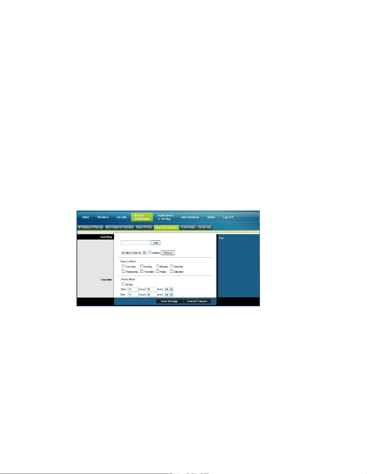
Control Access to t he Gateway
Use the Keyword List to enter the keywords you wish to block. If any of these
keywords appears in the URL of a website, access to the site will be blocked. Note
that only the URL is check, not the content of each webpage.
Access Restrictions > Time of Day Rules
Use the Access Restrictions Time of Day Rules page to configure web access filters to
block all Internet traffic to and from specific network devices based on day of week
and time of day settings that you select.
Select the Time of Day Rules tab to open the Access Restrictions Time of Day Rules
Page. The following illustration is an example of the Access Restrictions Time of Day
Rules page.
Note: The residential gateway uses the network time of day clock that is ma naged by
your data service provider. The time of day clock must be accurate and represent the
time of day in your time zone for this feature to operate properly. Verify that the
Status and Set Time pages reflect the correct time of day. If they do not reflect the
correct time of day, contact your data service provider. You can also adjust your
settings to account for the difference.
Access R estr i cti o n s Ti me o f Day Ru l es Page Descr i p ti o n
Use the descriptions and instructions in the following table to configure the time of
da y rules for your residential gateway. After you make your selections, click Save
Settings to apply your changes or Cancel Changes to cancel.
OL-30824-01 71
Page 72

Control Access to th e Gatew ay
Section Field Description
To d F ilter Add
Allows you to add a new Time of Day access filter or rule.
Enter the name of the filter and click the Add key to add the
filter to the list. Time of Day rules are used to restrict Internet
access based on the day and time.
Remove
Removes the selected filter from the Time of Day filter list
Schedule
Days to Block
Allows you to control access based on days of the week
Time to Block
Allows you to control access based on time of day
Access Restrictions > User Setup
Use the Access Restrictions User Setup page to set up additional account s and user
profiles for household members. Each profile can be assigned customized levels of
Internet access as defined by the access rules assigned to that user's profile.
Important: These additional accounts do not grant administrative access to the
gateway.
Note: Once you define and enable user profiles, each user must sign-on each time
they wis h to access the Int ernet. The user can sign-on when the pop-up sign-on
screen appears in their Web browser. The user must enter their correct user name
and password in order t o gain Internet a ccess.
Select the User Setup tab to open the Access Restrictions User Setup page.
72 OL-30824-01
Page 73

Control Access to t he Gateway
Access R estr i cti o n s User Setu p Pag e D escr i p ti o n
Section
Field Description
Select the Content Rule for the current user profile. Content Rules must first be defined by
Enter the amount of time in minutes that the user will be granted Internet access beginning
Use the descriptions and inst ructions in the following ta ble to configu re t he user
setup for your residential gateway. After you make your selections, click Save
Settings
to apply your changes or Cancel Changes to cancel.
User
Configure
Add User
Allows you to add a new user profile. Enter the name of the user and click the Add User
button to add the user to the list.
User Settings
Allows you to edit a user profile b y using the drop-down menu to edit a user profile. The
drop-down menu allows you to recall the profile to be edited. User names and passwords
are case-sensitive.
Make sure to check the Enable box to activate the user profile. If a profile is not active, that
user will not have any access to the Internet.
To remove a user profile, use the drop-down menu to select the user to be removed and
click the Remove User button.
Password
Enter the selected user's password in this field. Each user must enter their User Name and
Password each time they use the Internet. User names and passwords are case-sensitive.
Note: The residential gateway will allow each user access to the Internet, subject to the
rules selected on this page for that user.
Re-Enter Password
Re-enter the same password for confirmation of the password in the previous field.
Trusted User
Check this box if the currently selected user is to be designated a trusted user. Trusted
users are not subject to Internet access rules.
Content Rule
going to the Rules Configuration page. You can access the Rule Configuration page by
clicking on the “Basic Rules” tab on this page.
Time Access Rule
Select the Time Access Rule for the current user profile. Time Access Rules must first be
OL-30824-01 73
defined by going to the Time of Day Rules page. You can access the Time of Day Rules
page by clicking on the “Time of Day Rules” tab on this page.
Session Duration
1440 minutes [Factory default when a user is created. Otherwise, it is 0 (zero)].
at the time they sign on using their User Name and Password.
Note: Set the Session Duration to 0 (ze ro) to preve nt session timeout.
Page 74

Control Access to th e Gatew ay
Section Field Description
session will be closed automatically. In order to regain Internet access, the user must log in
Local Log
Last Occurence
Inactivity Time
60 minutes [Factory default when a user is created. Otherwise, it is 0 (zero)].
Enter the amount of time during a user session where there is no Internet access activity,
indicating that the user is no longer online. If the inactivity timer is triggered, the user
again with their User Name and Password.
Note: Set the Inactivity time value to 0 (zero) to prevent session timeout.
Access Restrictions > Local Log
This page allows you to track, by user, any attempts made by that user to access
Internet sites that are restricted. From this page you can also view events captured
by t he parental control event-reporting feature.
Select the Local Log tab to open the Access Restrictions Local Log page.
The following illustration is an example of the Access Restrictions Local Log page.
Section Field Description
Parental Control - Event
Log
Displays the time of the most recent attempt to access a
restricted Internet site
Action
Displays the action taken by the system
Target
Displays the URL of the restricted site
User
Displays the user who attempted a restricted site
Source
Display s the IP address of the PC that was used when
attempting to access a restricted web site
74 OL-30824-01
Page 75
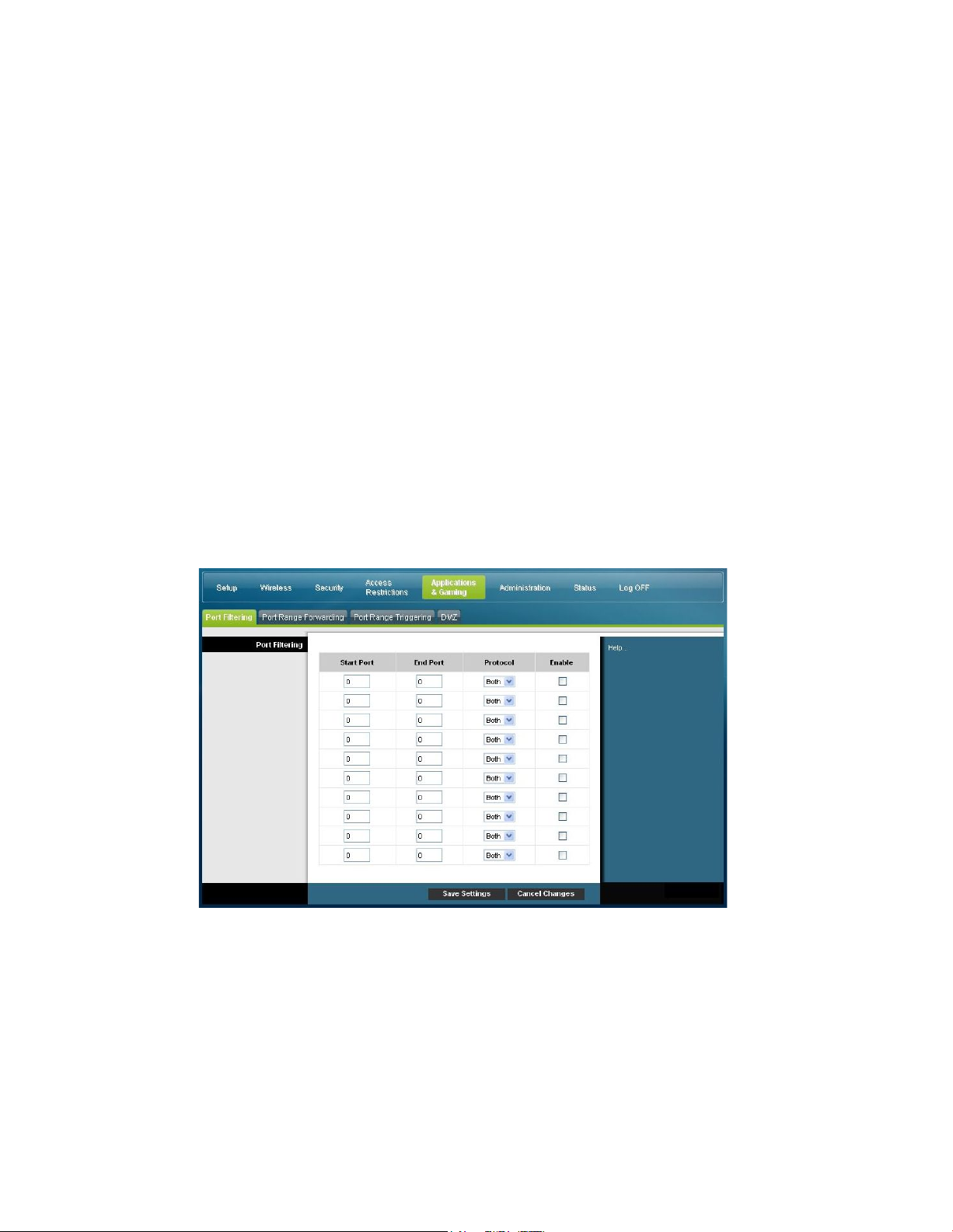
Configur e A pplications and Gaming
Configure Applica tions and G aming
Overview
Most well-known Internet applications are supported by Application Layer
Gateways (ALGs). ALGs automatically adjust the gateway firewall to allow data to
pass without making any custom settings. We recommend that you test your
app lication before making changes in this section.
Applications & Gaming > Port Filtering
Use this window to configure transmission control protocol (TCP) and user
datagram protocol (UDP) port filters. These filters prevent a range of TCP/UDP
ports from accessing the Internet. You can also p revent PCs from sending outgoing
TCP/UDP traffic to the WAN on specific IP port numbers. This filter is not IP
address- or MAC address- specific. The system blocks the specified port ranges for
all PCs.
Select the Port Filtering tab to open the Applications & Gaming Port Filtering page.
Applica t ions a nd G a ming Port Filt e ring P a ge De s c ript ion
Use the descriptions and instructions in the following table to configure the port
filtering for applications and gaming features used on your residential gateway.
Click the Enable checkbox to enable port forwarding for the relevant application.
After you make your selections, click Save Settings to apply your changes or Cancel
Changes to cancel.
OL-30824-01 75
Page 76

Configure Applicat ions a nd Gaming
Section Field Descriptio n
Port Filtering Start Po rt:
This is the beginning of the port range. Enter the beginning of the
range of port numbers (external ports) used by the server or Internet
application. Check with the software documentation of the Internet
application for more information if necessary.
End Port:
This is the end of the port range. Enter the end of the range of port
numbers (external ports) used by the server or Internet application.
Check with the software documentation of the Internet application
for m ore information if necessary.
Protocol
Select one of the following protocols:
TCP
UDP
Bo th
Enable:
Check this box to enable filtering on the specified ports.
Applications & Gaming > Port Range Forwarding
Important: The gateway normally implements a feature called Port Translation. Port
Tra nslation monitors what ports are actually being used by your PCs or other
devices on your LAN. This monitoring provides an added level of security beyond
what the firewall provides. However, there are some applications that require the
gatewa y to use specific ports to connect over the Internet.
Use Port Range Forwarding to forward ports from the pu blic I nternet to specific IP
addresses in your local network. Select the Port Range Forwarding tab to open the
Applications & Gaming Port Range Forwarding page.
For the Start and End Port, select a port from the recommended 49152 - 65535 range.
Keep in mind that ports used are program specific so check which ones the progra m
requires to be forwarded. Type the port number or range in both boxes. In the IP
Address box type the name of the computer’s IP address to which this is to apply.
Note: Port Range Forwarding continually exposes the selected ports to the public
Internet. This means that the gateway’s firewall is no longer active on these ports.
The device with the forwarding IP address can be exposed to hacker attacks while
the port ra nge is being forwarded.
76 OL-30824-01
Page 77
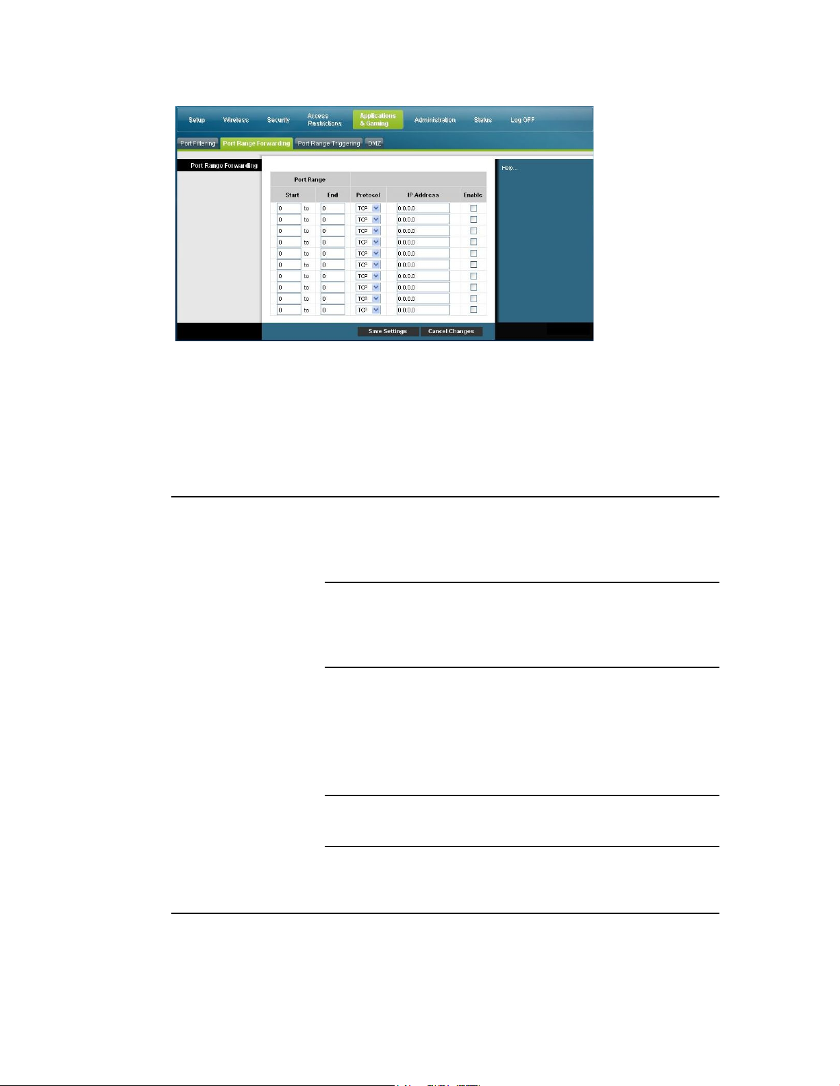
Configur e A pplications and Gaming
Section
Field Description
65535 range. Keep in mind that ports used are program specific
65535 range. Keep in mind that ports used are program specific
Applica t ions a nd G a ming Port Ra n ge Forw ard Pag e De s c ript ion
Use the descriptions and inst ructions in the following ta ble to configu re t he port
range forwarding for the residential gateway. Select enable for each. After you make
your selections, click Save Settings to apply your changes or Cancel Changes to
cancel.
Port Range Forwarding Start
For the Start port, select a port from the recommended 49152 -
so check which ones the program requires to be forwarded.
End
For the End port, select a port from the recommended 49152 -
so check which ones the program requires to be forwarded.
Protocol
Select one of the following protocols:
TCP
UDP
Both
IP Address
Enter the computer’s IP address to which this is to apply.
Enable
Check this box to enable port forwardin g for the specified ports
OL-30824-01 77
and IP addresses.
Page 78

Configure Applicat ions a nd Gaming
Applications & Gaming > Port Range Triggering
65535 range. Keep in mind that ports used are program specific
n mind that ports used are program specific
65535 range. Keep in mind that ports used are program specific
Port range triggering is a way to dynamically forward ports to a LAN PC that needs
them at a particular time. That particular time is when it runs a certain application
that performs some event that trigger the router. This event must be an outbound
access of a particular port range.
Select the Por t Range Triggering tab t o open the Applica tions & Gaming Port Ra nge
Triggering page.
Applica t ions a nd G a ming Port Ra n ge Triggering P a ge De s c ript ion
Use the descriptions and inst ructions in the following ta ble to configu re t he port
range triggering for the residential gatewa y. Select enable for each. After you make
your selections, click Save Settings to apply your changes or Cancel Changes to
cancel.
Section Field Description
Port Range Triggering
Triggered Range Start Port
For the Start port, select a port from the recommended 49152 -
so check which ones the program requires to be forwarded.
End Port
For the End port, select a port from the recommended 49152 65535 range. Keep i
so check which ones the program requires to be forwarded.
Forwarded Range
Start Port
For the Start port, select a port from the recommended 49152 -
so check which ones the program requires to be forwarded.
78 OL-30824-01
Page 79
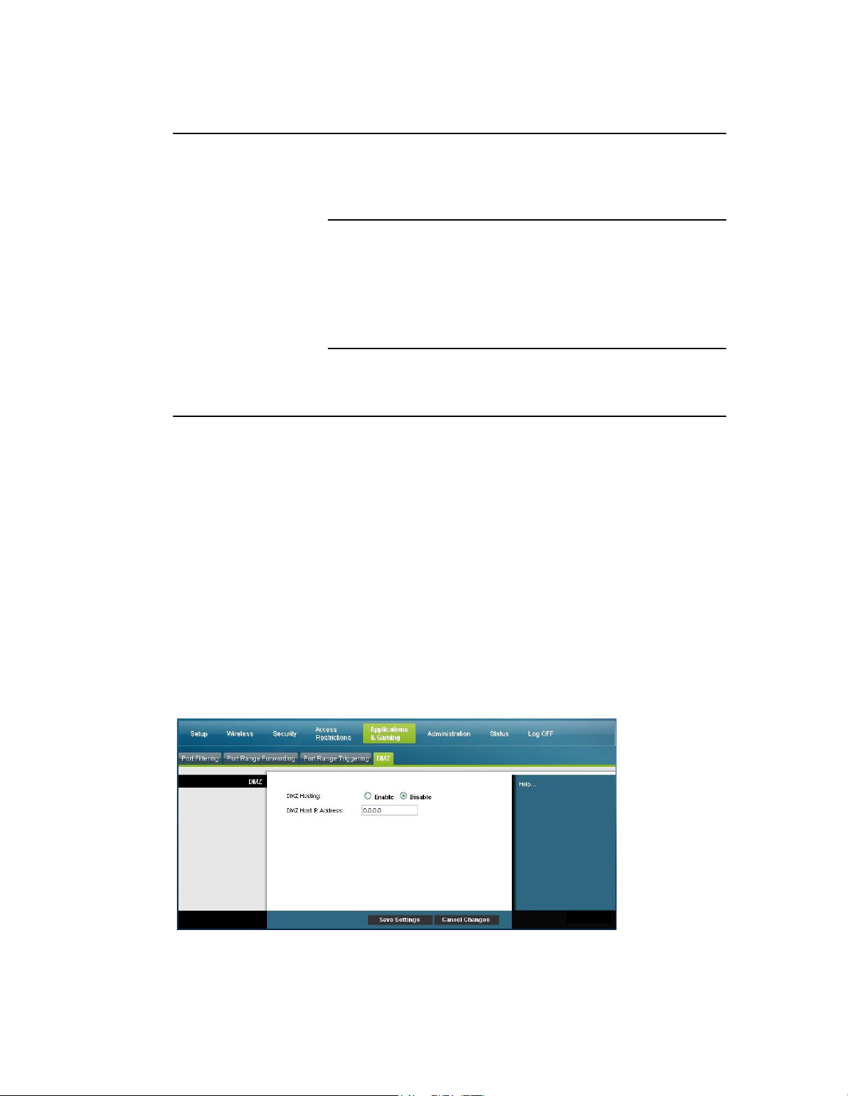
Configur e A pplications and Gaming
Section Field Description
65535 range. Keep in mind that ports used are program specific
End Port
For the End port, select a port from the recommended 49152 -
so check which ones the program requires to be forwarded.
Protocol
Select one of the following protocols:
TCP
UDP
Both
Enable
Click the Enable checkbox to enable port range triggering for
the relevant application.
Applications & Gaming > DMZ
Use this page to configure an IP address whose ports are directly exposed to the
public Internet or to the Wide Area Network (WAN). Demilitarized Zone (DMZ)
hosting is commonly referred to as "exposed host," and allows you to specify a
recipient of WAN traffic that Network Address Translation (NAT) is unable to
translate to a known local PC.
A DMZ is typically used by a company that wants to host its own Internet server.
DMZ allows one IP a ddress to be placed on the Internet side of the gatewa y firewall
while others remain protected behind the firewa ll.
The DMZ allows a device to be directly accessible to Internet traffic, such as a web
(HTTP) server, an FTP server, an SMTP (e-mail) server, a nd a domain name system
(DNS) server. Select the DMZ tab to open the Applications & Gaming DMZ page.
OL-30824-01 79
Page 80

Configure Applicat ions a nd Gaming
Applica t ions a nd G a ming DMZ P a ge Description
DMZ Host IP Address
DMZ allows one IP address to be unprotected while others remain
Use the descriptions and inst ructions in the following ta ble to configu re t he port
range triggering for the residential gateway. Select enable for each DMZ Host IP
address. After you make your selections, click Save Settings to apply your changes
or Cancel Changes to cancel.
Section Field Description
DMZ
DMZ Hosting
Select the desired option:
Enable
Disable (factory default)
protected. Enter the IP address of the computer y ou want to
expose to the Internet in this field.
80 OL-30824-01
Page 81

Man ag e t h e Gatew ay
Manage the Gatew ay
Administration > Management
The Administration Management page allows the network’s administrator t o
manage specific gateway functions for access and security. Select the Management
tab to open the Administration Management page.
Important: The following page displays when DHCP (factory default) is the
Connect ion Mode. The pa ge that disp la ys when Static IP is selected is shown and
described later in this section.
Administra t ion Ma na ge ment P a ge De s c rip tio n
Use the descriptions and inst ructions in the following ta ble to configu re t he
administration management for the res idential gateway when DHCP or Static IP
connection mode is selected. After you make your selections, click Save Settings to
apply your changes or Cancel Changes to cancel.
OL-30824-01 81
Page 82

Manage the Gateway
Field Description
Gateway Setup
(WAN)
Internet Connection
Connection Mode This setting allows you to determine how the
WAN (or gateway interface to the Internet) obtains its IP address.
DHCP (factory default)
Type
Allows the gateway to obtain a public IP address automatically
Static IP
Allows you to specify the WAN IP address an d corresponding
server information as static or fixed values that will be used
whenever the gateway goes online
82 OL-30824-01
Page 83

Man ag e t h e Gatew ay
Field Description
Enter the primary domain name server IP address(es) provided by
the largest packet size permitted for Internet transmission. . The
Internet IP Address
Enter the gateway’s IP address (as seen from the Internet)
Subnet Mask
Enter the gateway’s subnet mask (as seen from the Internet,
including your service provider)
Default Gateway
Enter the default gateway of the service provider’s server
Primary DNS
your service provider. This is required.
Secondary DNS
Enter the secondary domain name server IP address(es) provided
MTU
by your service provider. This is optional.
MTU size
MTU is the Maximum Transmission Unit. The MTU size specifies
Gateway Access
Local Access
factory default = 0 (1500 bytes)
Current User Name
Identifies the currently logged in user
Change Current User Name to
This field allows you to change your user name. If you want to
change your user name, enter your new user name in this field
and click Save Settings to apply the change.
Note: The factory default user name is a blank field.
Change Password to
This field allows you to change your password. If you want to
change your password, enter your new password in this field.
Then, re-enter your new password in the Re-Enter New Password
field and click Save Settings to apply the change.
Note: The factory default password is a blank field.
Re-Enter New Password
Allows you to re-enter the new password. You must enter the
same password as the one entered in the prev ious field Change
Password to. After you re-enter your new password, click Save
Settings to apply the change.
OL-30824-01 83
Page 84

Manage the Gateway
Field Description
protocol HTTP is required for remote management. To remotely
UPnP
UPnP
applications, such as gaming and videoconferencing. If you want
IGMP
IGMP Proxy
Remote A ccess Remote Management
Allows you to enable to disable remote management. This feature
allows you to access and manage your gateway settings from the
Internet when you are away from home. To allow remote access,
select Enable. Otherwise, keep the default setting, as Disable. The
access the device, enter https://xxx. xxx.xxx.xxx: 808 0 (the x's
represent the device's public Internet IP address, and 8080
represents the specified port) in your web browser's Address field.
Management Port
Enter the port number that will be open to outside access. The
factory default setting is 8080. This port must be used when you
establish a remote connection.
Universal Plug and Play (UPnP) allows Windows XP and Vista to
automatically configure the Gateway for various Internet
to use UPnP, keep the default, Enable. Otherwise, select Disable.
Internet G roup Multicast Protocol (IG MP) is used to establish
membership in a multicast group and is commonly used for
multicast streaming applications. For example, you may have
Internet Protocol Telev ision (IPTV) with multiple set-top boxes on
the same local network. These set-top boxes have different video
streams running simultaneously, so you should use the IGMP
feature of the Router.
IGMP forwarding (proxying) is a sy stem that improves
multicasting for LAN-side clients. If the clients support this
option, keep the default, Enable. Otherwise, select Disable.
84 OL-30824-01
Page 85

Man ag e t h e Gatew ay
Section
Field Description
E-Mail Address for Alert Log s
Administration > Repor ting
Administration reporting allows you to email various system activities to your email
address.
Select the Reporting tab to open the Administration Reporting p age.
Use the descriptions and inst ructions in the following ta ble to configu re t he
reporting feature on the gateway. After you make your selections, click Save
Settings to apply your changes or Cancel Changes to cancel.
Repo rting E-Mail Alerts
If enabled, an e-mail will be sent immediately if any reportable
events are detected. To use this feature, provide the necessary e-
mail address information.
SMTP Mail Server
Enter the address (domain name) or IP address of the Simple Mail
Transport Protocol (SMTP) serv er y ou use for outg oing e-mail.
Enter the e-mail address that should receive the logs.
OL-30824-01 85
Page 86

Manage the Gateway
View Log
To view the logs, complete the following steps.
1 Click V i e w Lo g . A new window opens with the log data page.
2 To view a particular log, select one of the following options from the Type drop-
down menu:
All
Access Log
Firewall Log
VPN Log
3 After the log data is displayed, use one of the following options:
Click the Page Refresh button to update the log.
Click the Clear button t o clear all the inf orma tion in the current log.
Click the Previous Page button to go back to the information previously
displayed.
Click the Next Page button to see the next section of the log, if available.
86 OL-30824-01
Page 87

Man ag e t h e Gatew ay
Administration > Diagnostics
Section
Field Description
Start Test
Administration dia gnostics allow you to check the status of you r Internet connection
by using a Ping test.
Select the Diagnostics tab to open t he A dministration Diagnost ics page.
Use the descriptions and instructions in the following table to configure the
diagnostics feature on the gateway. After you make your selections, click Save
Settings to apply your changes or Cancel Changes to cancel.
Ping Test
Ping Test Parameters Ping Targ et IP
The IP address that y ou want to ping
Ping Size
The size of the packet you want to use
Number of Pings
The number of times you wish to ping the target device
Ping Interval
The time period (milliseconds) between each ping
Ping Timeout
The desired time period (milliseconds) of the timeout. If no
response is received within this ping period, the ping test is
considered a failure
To start a test, complete the following steps.
1 Click Start Test to begin the text. A new page opens and
displays a summary of the test results.
2 Click the Save Setting s to save the test results or click
Cancel Changes to cancel the test.
OL-30824-01 87
Page 88

Manage the Gateway
Administration > Backup & Restore
Section
Field Description
Administration Backup & Restore allows you to back up you configuration of the
Gateway and store it on your computer. You can use this file to restore a previously
saved configuration for your Gateway.
Select the Back Up & Restore tab to open the Administration Back Up & Restore
pa ge.
CAUTION:
Restoring a co nfiguration file will destroy (overwrite) all of the existing
settings.
Back Up Configuration
Restore Configuration
Use the Back Up Configuration feature to save a copy of the
current configuration and store the file on your computer. Click
Back Up to start the download.
Use the Restore Configuration feature to restore a previously
saved configuration file. Click Bro wse to select the config uration
file, and then click Restore to load the configuration file to the
device.
88 OL-30824-01
Page 89

Man ag e t h e Gatew ay
Administration > Facto ry Defaults
The Administration Factory Defaults page allows you to restore the configuration to
its factory default settings. Select the Factor y Defaults tab to open the
Administration Factory Defaults page.
CAUTION:
If you restore the factory defaults, the gateway will lose all o f the settings yo u
have entered. Before you reset the gateway to its factory default settings, write
down all of your custom settings. After the defaults have been restored, you
will hav e to re-enter all o f your config uration setting s.
Restore Factory Defaults
To restore factory defaults, click Restore Factory Defaults to reset all configuration
settings to their default values. Any settings you have saved will be lost when the
default settings are restored.
OL-30824-01 89
Page 90

Monitor Gateway Status
Monitor Gateway S tatus
interface, which is used to connect to the cable modem termination
This section describes the options available under the Status tab that you can use to
monitor the status of the residential gateway and to perform diagnostics on the
device and the network.
Status > Gateway
The Gateway Status page displays information about the gateway and its current
settings. The on-screen informa t ion varies depending on t he Internet Connection
type you use.
Select the Gateway tab to open the Status Gateway screen. Click Refresh to update
the data displayed on-screen.
Use the descriptions in the following table to review the status of your ga teway and
you r Internet connection.
Section Field Description
Gateway Information Firmware Version
The version number of the firmware.
MAC Address (CM MAC Address)
A unique alphanumeric address for the cable modem coaxial
90 OL-30824-01
system (CMTS) at the headend. A media access control (MAC)
address is a hardware address that uniquely identifies each node
of a network.
Current Time
The time, based on the time zone selected on the Basic Setup page
is displayed.
Page 91

Mo n itor G at eway St at u s
Section Field Description
Internet Connectio n
IP Address
Display s the IP address of the WAN interface. This address is
assigned to the gateway when it goes online.
Subnet Mask
Display s the subnet mask for your WAN port. This address is
automatically assigned to y our WAN port by your ISP except
when a static IP address is set up.
Default Gateway
The IP address of the ISP's Default Gateway.
DNS1-3
The DNS IP addresses currently used by the gateway.
WINS
The WINS IP address currently used by the gateway.
Status > Local Network
The Local Network Status page displays information about the status of the local
area network.
Select the Local Network tab to open the Status Local Network page. Click Refresh
to update the data on the page.
Use the following table to review the status of your gateway and your Internet
connect ion.
Section Field Description
Local Netwo rk MAC Address
A unique alphanumeric address for the private LAN home network.
OL-30824-01 91
Page 92

Monitor Gateway Status
Section Field Description
A MAC address is a hardware address that uniquely identifies each
DHCP Client Table
node of a network .
IP Address
Display s the IP address for the LAN subnet
Subnet Mask
Display s the subnet mask for your LAN
DHCP Server
Display s the status of your local DHCP server (Enabled or Disabled)
Starting IP Address
Displays the beginning of the range of IP addresses used by the
DHCP server in your gateway
End IP Address
Displays the end of the range of IP addresses used by the DHCP
server
Click DHCP Client Table to show which de vice s are attached to y our
LAN that have been issued IP addresses by the DHCP server in the
gateway. On the DHCP Client Table page, you will see a list of DHCP
clients (computers and other network devices) with the following
information: Client Host Names, IP Addresses, MAC Addresses, and
the length of time before their assigned IP addresses expire. To
retrieve the most up-to-date information, click Refresh. To exit this
page and return to th e Local Network page, click Close.
The following illustration shows an example of the DHCP Client
Table.
92 OL-30824-01
Page 93

Mo n itor G at eway St at u s
ARP/RARP Table
Click ARP/RARP Table to see a complete list of all devices that are
conn ected to y our network . To retrieve the most up-to-date
information, click Refresh. To exit this pag e and return to the Local
Network page, click Close.
The following illustration shows an example of the ARP/RARP
Table.
Status > Wireless
The Wireless Network Status page displays ba sic information about the wireless
network of the gateway.
Select the Wireless tab to open the Sta tus Wireless page. Click Refresh to update the
da t a on the page.
OL-30824-01 93
Page 94

Monitor Gateway Status
Wireless
MAC Address
Status W i r el ess Pag e D escr i p ti o n
Use the following table to review the status of your wireless network.
Section F ield Descriptio n
Network
Display s the MAC Address of your gateway's local wireless access point
Radio Band
Displays one of the following radio band frequencies currently in operation:
2.4 GHz
5 GHz
2.4 and 5 GHz
Note: Not all products support the 5 GHz radio band.
Network Name (SSID)
Displays the name or service set identifier (SSID) of your wireless access
point
Channel Width
Displays the channel bandwidth setting selected on the Basic Wireless
Settings page
Wide Channel
Displays the Wide Channel setting selected on the Basic Wireless Settings
page
Standard Channel
94 OL-30824-01
Displays the Standard Channel setting selected on the Basic Wireless
Settings page
Security
Displays the security method used by your wireless network
SSID Broadcast
Displays the status of the g ateway's SSID Broadcast feature
Page 95

Mo n itor G at eway St at u s
Status > DOCSIS WAN
DOCSIS WAN Status displays information about the system of your cable modem.
Select the DOCSIS WAN tab to open the Status DOCSIS WAN page.
DOCSIS WAN Page Description
Use the descriptions in the following table to review the status of your DOCSIS
WAN network.
Section Field Description
About Model
Displays the name of the residential gateway
Vendor
Displays the manufacturer of the residential gateway
Hardware Rev ision
Displays the revision of the circuit board design
Serial Number
Displays the unique serial of the residential gateway
OL-30824-01 95
Page 96

Monitor Gateway Status
Section Field Description
alphanumeric address for the cable modem coaxial interface, which is used
Firmware Build Time
Downstream
Channels 1-8
Upstream
Channels 1-4
MAC Address (CM MAC Address)
Display s the CM MAC Address. The CM MAC Address is a unique
to connect to the CMTS at the headend. A MAC address is a hardware
address that uniquely identifies each node of a network.
Bootloader Revision
Displays the boot revision code version
Current Software Revision
Displays the revision version of the firmware
Firmware Name
Displays the name of the firmware
Displays the date and time the firmware was built
Cable Modem Status
Display s one of the possible current states of the gateway
Channels
Channels
Displays the power level and the signal to noise ratio of the active
downstream channels
Displays the power level of the active upstream channels
96 OL-30824-01
Page 97

Frequently Asked Questions
Frequently A sked Questions
Q. How Do I Configure TCP/IP P rot oc ol?
A. To configure TCP/IP protocol, you need to have an Ethernet Network Interface
Card (NIC) with TCP/IP communications protocol installed on your system.
TCP/IP is a communications protocol used to access the Internet. This section
contains instructions for configuring TCP/IP on your Int ernet devices to operate
with the residential ga teway in Microsoft Windows or Macintosh environment s.
TCP/IP protocol in a Microsoft Windows environment is different for each
operating system. Follow the appropriate instructions in this section for your
operating system.
Configuring TC P/ IP on Window s 2000 Systems
1 Click Start, select Settings, and choose Network and Dial-up Connections.
2 Double-click the Local Area Connection icon in the Network and D ia l-up
Connect ions window.
3 Click Properties in the Local A rea Connection Status window.
4 Click Internet Protocol (TCP/IP) in the Loca l Area Connection Properties
window, and then click Properties.
5 Select both Obtain an IP address automatically and Obtain DNS server address
automatically in the Internet Protocol (TCP/IP) Propert ies window, and then
click OK.
6 Click Yes to restart your computer when the Loca l Network window opens. The
computer restarts. The TCP/IP protocol is now configured on your PC, a nd your
Ethernet devices are ready for use.
7 Try to access the Internet. If you cannot access the Internet, contact your service
provider for further assistance.
Configuring TC P/ IP on Window s XP Sy s tems
1 Click Start, and depending on your Start menu setup, choose one of the
following options:
If you are using the Windows XP Default Start Menu, select Connect to,
choose Show all connections, and then go to step 2 .
If you are using the Windows XP Classic Start Menu, select Settings, choose
Network Connections, click Local Area Connection, a nd then go to step 3.
2 Double-click the Local Ar ea Connection icon in the LAN or High-Speed Internet
section of the Network Connections window.
3 Click Properties in the Local A rea Connection Status window.
4 Click Internet Protocol (TCP/IP), and then click Properties in the Loca l Area
Connect ion Properties window.
OL-30824-01 97
Page 98

Frequently Asked Questions
5 Select both Obtain an IP address automatically a nd Obtain DNS server address
automatically in the Internet Protocol (TCP/IP) Propert ies window, and then
click OK.
6 Click Yes to restart your computer when the Loca l Network window opens. The
computer restarts. The TCP/IP protocol is now configured on your PC, and your
Ethernet devices are ready for use.
7 Try to access the Internet . If you ca nnot access the Internet, contact your service
provider for further assistance.
Configuring TC P/ IP on Mac intosh Systems
1 Click the Apple icon in the upp er-left corner of the Finder. Scroll down to
Control Panels, a nd then click TCP/IP.
2 Click Edit on the Finder at the top of the page. Scroll down to the bottom of the
menu, and then click User Mode.
3 Click Advanced in the U ser Mode window, and t hen click OK.
4 Click the Up/Down selector arrows located to the right of the Connect Via
section of the TCP/I P window, and then click Using DHCP Server.
5 Click Options in the TCP/IP window, and then click Active in the TCP/IP
Options window.
Note: Make sure that the Load only when needed option is unchecked.
6 Verify that the Use 802.3 option located in the upper-right corner of t he TCP/IP
window is unchecked. If there is a check mark in the opt ion, uncheck the option,
and t hen click Info in the lower-left corner.
7 Is there a Hardware Address listed in this window?
If yes, click OK. To close the TCP/IP Control Panel window, click File, a nd
then scroll down to click Close. You have completed this procedure.
If no, you must power off your Macintosh.
8 Wit h the power off, simultaneously press and hold down the Command
(Apple), Option, P, a nd R keys on your keyboard. Keeping those keys pressed
down, power on your Macintosh but do not release these keys until you hear t he
Apple chime at least three times, then release the keys and let the computer
restart.
9 When your computer fully reboots, repeat steps 1 through 7 to verify that all
TCP/IP settings are correct. If your computer still does not have a Hardware
Address, contact your authorized Apple dealer or Apple technica l support center
for further assistance.
Q. How Do I Rene w the IP Addre s s on My P C?
A. If your PC cannot access t he Internet after the residential gateway is online, it is
possible that your PC did not renew its IP address. Follow the appropriate
instructions in this section for your operating system to renew the IP address on
your PC.
98 OL-30824-01
Page 99

Frequently Asked Questions
Rene w ing t he IP Addres s on Wind ow s 9 5 , 9 8 , 9 8 S E , and ME Systems
1 Click Start, a nd then click Run to open the Run window.
2 Type winipcfg in the Open field, and click OK to execute the winipcfg
command. The IP Configuration window op ens.
3 Click the down arrow to the right of the top field, and select the Ethernet a dapt er
that is installed on your PC. The IP Configuration window displays the Ethernet
ada pter information.
4 Click Release, and then click Renew. The IP Configuration window displays a
new IP address.
5 Click OK to close the IP Configuration window, you have completed this
procedure.
Note: If you cannot access the Internet, contact your service provider for further
assistance.
Rene w ing t he IP Addres s on Wind ow s NT, 20 0 0 , or XP S y s t e ms
1 Click Start, a nd then click Run. The Run window opens.
2 Type cmd in the Open field and click OK. A window with a command prompt
opens.
3 Type ipconfig/release at the C:/ prompt and press Enter. The system releases
the IP address.
4 Type ipconfig/renew at the C:/ prompt and press Enter. The system displays a
new IP address.
5 Click the X in the upper-right corner of the window to close the Command
Prompt window. You have completed this procedure.
Note: If you cannot access the Internet, contact your service provider for further
assistance.
Q. What if I don' t s ubs c ribe t o c a ble TV?
A. If cable TV is available in your area, data service may be made available with or
without subscribing to cable TV service. Contact your local service provider for
complete information on cable services, including high-speed Internet access.
Q. How do I arrange f or ins t a lla t ion?
A. Call your service provider to inquire about professional installation. A
professional installation ensures proper cable connection to the modem and to your
PC, and it ensures the proper configu ra tion of all hardware and software settings.
Contact your service provider for more information about installation.
OL-30824-01 99
Page 100

Frequently Asked Questions
Q. How does t he reside nt ia l ga t e w a y conne c t t o my c ompute r?
A. The residential gateway connects to the PC using a wireless connection or the
10/100/1000BASE-T Ethernet port on your PC. If you want to use an Ethernet
interface, Ethernet cards available from your local PC or office supply retailer, or
from your service provider. For best performance over an Et hernet connection, your
PC should be equipped with a Gigabit Ethernet card.
Q. Afte r my re s ide nt ia l ga t e w a y is conne cted, ho w do I a c c e s s t he Int e rne t ?
A. Your local service provider becomes your Internet Service Provider (ISP). They
offer a wide range of services including e-mail, chat, news, a nd information services.
Your service provider will provide the software you will need.
Q. Can I wa t c h TV and surf t he Interne t a t the same t ime?
A. Absolutely! If you subscribe to cable television service, you can watch TV and
use your residential gateway at the same time by connecting your TV and your
residential gateway to the cable network using an optional cable signal splitter.
Com m on Troubl eshooti ng Is sues
I don't understa nd t he front pa ne l s t a t us indic a t ors
See Front Panel LED Status Indicator Functions (on page 102), for more detailed
information on front pa nel LED st atus indicator operation and function.
T he reside nt ia l ga t e w a y does not re gis t e r a n E t he rne t c onne c t ion
Verify that your comp uter has an Ethernet card a nd that the Ethernet driver
software is properly installed. If you purchase and install an Ethernet card,
follow the installation instructions very carefully.
Verify the status of the front panel status indicator lights.
T he reside nt ia l ga t e w a y does not re gis t e r a n E t he rne t c onne c t ion a f t e r c onne c t ing t o a hub
If you are connecting multiple PCs to the residential gateway, you should first
connect the modem to the uplink port of the hub using the correct crossover cable.
The LINK LED of the hub will illuminate continuously.
The residential gateway does not register a cable connection
The modem works with a standard 75-ohm RF coaxial cable. If you are using a
different cable, your residential gateway will not function properly. Contact your
cable service provider to determine whether you are using the correct cable.
Your NIC card or USB interface may be malfunctioning. Refer to the
troubleshooting information in the NIC or USB documentat ion.
100 OL-30824-01
 Loading...