

Page 1

Cisco D9865
Satellite Receiver
Installation and Operation Guide
Page 2

Please Read This Entire Guide
Veuillez lire entièrement ce guide
Bitte das gesamte Handbuch durchlesen
Sírvase leer completamente la presente guía
Please read this entire guide before you install or operate this product. Give
particular attention to all safety statements.
Important:
Veuillez lire entièrement ce guide avant d'installer ou d'utiliser ce produit. Prêtez
une attention particulière à toutes les règles de sécurité.
Zu beachten:
Bitte lesen Sie vor Aufstellen oder Inbetriebnahme des Gerätes dieses Handbuch in
seiner Gesamtheit durch. Achten Sie dabei besonders auf die Sicherheitshinweise.
Importante:
Sírvase leer la presente guía antes de instalar o emplear este producto. Preste
especial atención a todos los avisos de seguridad.
Page 3

Notices
Trademark Acknowledgements
Cisco and the Cisco logo are trademarks of Cisco Systems, Inc. and/or its affiliates
in the U.S. and other countries. A listing of Cisco’s trademarks can be found at
www.cisco.com/go/trademarks
Manufactured under license from Dolby Laboratories. Dolby and the double-D
symbol are trademarks of Dolby Laboratories.
Other third party trademarks mentioned are the property of their respective
owners.
The use of the word partner does not imply a partnership relationship between
Cisco and any other company. (1007R)
Publication Disclaimer
Cisco Systems, Inc. assumes no responsibility for errors or omissions that may
appear in this publication. We reserve the right to change this publication at any
time without notice. This document is not to be construed as conferring by
implication, estoppel, or otherwise any license or right under any copyright or
patent, whether or not the use of any information in this document employs an
invention claimed in any existing or later issued patent.
.
Copyright
Licenses
© 2010 Cisco Systems, Inc. and/or its affiliates. All rights reserved. Printed in United States
of America.
Information in this publication is subject to change without notice. No part of this
publication may be reproduced or transmitted in any form, by photocopy,
microfilm, xerography, or any other means, or incorporated into any information
retrieval system, electronic or mechanical, for any purpose, without the express
permission of Cisco Systems, Inc.
This Cisco product (D9865 Satellite Receiver) contains, in part, certain free software
(“Free Software”) which has one or more types of licenses. The licenses may include
the GNU General Public License (GPL), which allows you to freely copy, modify
and redistribute the Free Software. Please go to: ftp://ftpeng.cisco.com/pub/
opensource/scientificatlanta/satellitereceiver to find additional information
regarding the Free Software, including a copy of the licenses and related
information. If you have any questions or problems accessing the link, please
contact: spvtg-external-opensource-requests@cisco.com
.
Page 4

Page 5
Safety Precautions
1. Read these instructions.
2. Keep these instructions.
3. Heed all warnings.
4. Follow all instructions.
5. Do not use this apparatus near water.
6. Clean only with dry cloth.
7. Do not block any ventilation openings. Install in accordance with the
manufacturer's instructions.
8. Do not install near any heat sources such as radiators, heat registers, stoves, or
other apparatus including amplifiers) that produce heat.
9. Do not defeat the safety purpose of the polarized or grounding-type plug. A
polarized plug has two blades with one wider than the other. A grounding type
plug has two blades and a third grounding prong. The wide blade or the third
prong is provided for your safety. If the provided plug does not fit into your
outlet, consult an electrician for replacement of the obsolete outlet.
10. Protect the power cord from being walked on or pinched particularly at plugs,
convenience receptacles, and the point where they exit from the apparatus.
11. Only use attachments/accessories specified by the manufacturer.
4035197 Rev C D9865 Satellite Receiver Installation and Operation Guide v
Page 6
Safety Precautions, Continued
12. Use only with the cart, stand, tripod, bracket, or table specified by the
manufacturer, or sold with the apparatus. When a cart is used, use caution when
moving the cart/apparatus combination to avoid injury from tip-over.
13. Unplug this apparatus during lightning storms or when unused for long
periods of time.
14. Refer all servicing to qualified service personnel. Servicing is required when the
apparatus has been damaged in any way, such as power-supply cord or plug is
damaged, liquid has been spilled or objects have fallen into the apparatus, the
apparatus has been exposed to rain or moisture, does not operate normally, or
has been dropped.
15. Do not expose this apparatus to dripping or splashing and ensure that no objects
filled with liquids, such as vases, are placed on the apparatus.
16. To completely disconnect this apparatus from the AC Mains, disconnect the
power supply cord plug from the AC receptacle.
17. The mains plug of the power supply cord shall remain readily operable.
18. Damage Requiring Service: Unplug this product from the wall outlet and refer
servicing to qualified service personnel under the following conditions:
(a) When the power-supply cord or plug is damaged.
(b) If liquid has been spilled, or objects have fallen into the product.
(c) If the product has been exposed to rain or water.
(d) If the product does not operate normally by following the operating
instructions. Adjust only those controls that are covered by the operating
instructions as an improper adjustment of other controls may result in damage
and will often require extensive work by a qualified technician to restore the
product to its normal operation.
(e) If the product has been dropped or damaged in any way.
(f) The product exhibits a distinct change in performance.
vi D9865 Satellite Receiver Installation and Operation Guide 4035197 Rev C
Page 7

Safety Precautions, Continued
19. Replacement Parts: When replacement parts are required, be sure the service
technician uses replacement parts specified by Cisco, or parts having the same
operating characteristics as the original parts. Unauthorized part substitutions
made may result in fire, electric shock or other hazards.
20. Safety Check: Upon completion of any service or repairs made to this product,
ask the service technician to perform safety checks to determine that the product
is in safe operating condition.
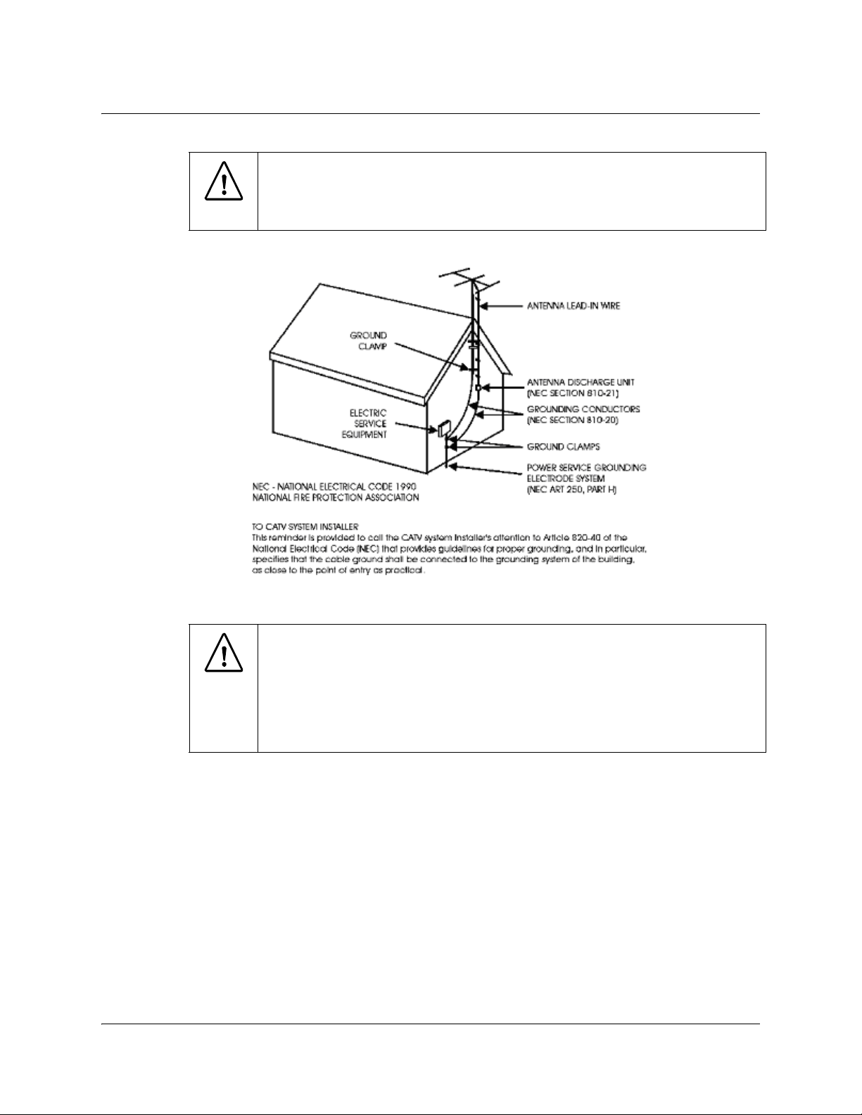
21. Outdoor Antenna Grounding: If an outside antenna or cable system is
connected to this product, ensure that the antenna or cable system is properly
grounded to provide protection against voltage surges and built-up static
charges. Appropriate sections of the National Electrical Code (NFPA 1990)
provide information with respect to proper grounding of the mast and
supporting structure, grounding of the lead-in wire to an antenna discharge
unit, connection to grounding electrodes, and requirements for the grounding
electrode (see Satellite Receiver and Satellite Antenna Satellite Antenna
Grounding).
Satellite Receiver & Satellite Antenna Grounding
Before you can operate your satellite receiver system, both the satellite receiver
chassis and the satellite antenna LNB connection(s) must be properly grounded. For
information about grounding your satellite receiver, also referred to as “receiver”,
and satellite antenna follow:
Grounding the receiver: The receiver ground connection is made from the shield
conductor attached to the RF coaxial cable “F” connector (rear panel RF IN input) to
an external grounding rod via a receiver/antenna grounding block. A separate
grounding wire connects the grounding block (and the satellite antenna LNB
grounding block) to the grounding rod.
Grounding the LNB and/or VHF/UHF antenna: The antenna ground connection is
made from the satellite LNB/antenna ground and/or the VHF/UHF terrestrial
antenna discharge unit to an external grounding rod via a receiver/antenna
grounding block.
General grounding information: The actual ground/cable connections made
depend on your site installation requirements, and on the type of satellite antenna
and/or VHF/UHF terrestrial antenna you have. If your satellite antenna
installation includes a dual-port LNB, both RF coaxial cables must be routed to the
grounding block. When connecting RF coaxial antenna cables to the grounding
block, looping the antenna cables as shown in the accompanying figure helps to
direct moisture away from the grounding block. Always choose the shortest route
possible when connecting RF coaxial cables to the receiver/antenna grounding
block and when connecting the grounding wire(s) to the grounding rod.
1)
1)Multi-strand (braided) shield surrounding the center conductor of the coaxial cable.
4035197 Rev C D9865 Satellite Receiver Installation and Operation Guide vii
Page 8
Safety Precautions, Continued
Important: Each ground connection must be made using a single (continuous)
piece of wire. Never splice two wires together when making a ground
connection. Corrosion and weathering can cause a poor electrical connection at
the splice which can lead to an ineffective and dangerous ground condition.
Figure 1. Outdoor antenna grounding
Important:
Install this product on a flat surface only, ensuring that all four
rubber feet are making full contact with the mounting surface. During
normal operation, it is recommended that physical contact be limited to
using the front panel buttons only. Do not place any other equipment
directly on top of the receiver, and prevent foreign objects from coming
into direct contact with the chassis. Subjecting this product to abnormal
impact may result in momentary interruption of video service.
viii D9865 Satellite Receiver Installation and Operation Guide 4035197 Rev C
Page 9

Safety Precautions (EU Market)
Mesures de Sécurité
Sicherheitmassnahmen
Precauciones de Seguridad
Warning
To prevent fire or electric shock:
• Do not expose this apparatus to rain or moisture.
• Avoid spilling liquids on or near this apparatus.
• Do not open the top cover of this apparatus.
• Do not push objects through openings in this apparatus.
• Refer servicing to qualified personnel only.
Attention
Afin d'éviter tout incendie ou choc électrique:
• Ne laissez pas cet appareil sous la pluie ou dans un endroit humide.
• Ne renversez pas de liquide sur ou à proximité de l'appareil.
• N'ouvrez pas le couvercle supérieur de l'appareil.
• N'insérez pas d'objet dans les ouvertures de l'appareil.
• Faites réparer votre appareil par une personne qualifiée.
Warnung
Advertencia
Um Feuer oder elektrischen Schock zu vermeiden:
• Keiner Nässe oder Feuchtigkeit aussetzen.
• Keine Flüssigkeiten auf oder in der Nähe des Gerätes verschütten.
• Den oberen Deckel nicht öffnen.
• Keine Gegenstande in die Geräteöffnungen stecken.
• Arbeiten am Gerät nur von qualifiziertem.
Para prevenir incendio o una descarga electrica:
• No exponga este aparato a la lluvia o a la humedad.
• Evite derramar liquidos en o cerca del aparato.
• No abra la cubierta superior de este aparato.
• No introduzca objetos a traves de las aberturas de este aparato.
• Mandelo a servicio unicamente donde existe personal calificado.
4035197 Rev C D9865 Satellite Receiver Installation and Operation Guide ix
Page 10

Safety Precautions (EU Market), Continued
Caution
• To protect this apparatus against damage from lightning storms and power-line
surges, or when you are not using this apparatus for a long period of time,
disconnect the power cord from the AC outlet.
• To disconnect the cord, pull it out by grasping the plug. Never pull the cord itself.
Additionally, never walk on, place objects on, or pinch the power cord.
• The top cover on this apparatus has openings for ventilation to protect it from
overheating. To ensure reliable operation, do not block or cover these openings
by placing this apparatus on a bed, sofa, rug, or any similar surface, or by placing
entertainment apparatus, lamps, books, or other objects on the top cover.
• Additionally, never place this apparatus near or over a radiator or heat register,
or a built-in installation, such as a bookcase or rack, unless the installation
provides proper ventilation.
• Locate this apparatus on a stable, vibration-free surface capable of supporting its
weight and size.
Précautions à prendre
• Afin de protéger votre appareil des orages et des surtensions de courant ou si
vous ne l'utilisez pas pendant une période prolongée, débranchez de la prise
électrique du secteur.
• Pour débrancher, tirez sur la prise. Ne tirez jamais sur le cordon secteur. En outre,
ne marchez jamais sur le cordon, ne placez pas d'objet dessus et ne le coincez pas.
• Le couvercle supérieur de cet appareil comprend des ouvertures pour la
ventilation afin d'éviter qu'il ne chauffe trop. Pour assurer un bon
fonctionnement, ne bloquez pas ou ne couvrez pas ces ouvertures en plaçant cet
appareil sur un lit, un sofa, un tapis ou toute autre surface sembiable. Ne posez
pas de lampes, livres ou tout autre objet sur le couvercle supérieur.
• De plus, il ne faut jamais mettre cet appareil près d'un radiateur ou tout autre
élément dégageant de la chaleur. Ne l'incorporez pas dans une installation
comme une bibliothèque, une étagére, à moins que l'installation offre une
ventilation appropriée.
• Installez cet appareil sur une surface dégagée, stable et sans vibration capable de
supporter son poids et sa taille.
x D9865 Satellite Receiver Installation and Operation Guide 4035197 Rev C
Page 11

Safety Precautions (EU Market), Continued
Vorsicht
• Um dieses Gerät vor Biltzschlag bzw. Stromüberladung zu schützen, oder wenn
das Gerät längere Zeit nicht benutzt wird, soll der Stecker aus der Steckdose
gezogen werden.
• Zum Abschalten immer am Stecker selbst und nie am Kabel ziehen. Außerdem
nie darauf treten, einen Gegenstand darauf legen oder das Kabel drücken.
• Die Oberseite des Gerätes hat Ventilationsöffnungen, die das Gerät vor
Überhitzung schützen. Um einwandfreies Funktionieren zu gewährleisten,
dürfen diese Öffnungen nicht blockiert oder verdeckt werden (z.B. nicht auf ein
Bett, Sofa, Teppich oder ähnliche Unterlagen stellen, oder Lampen, Bücher oder
ähnliches auf das Gerät stellen).
• Außerdem soll dieses Gerät nie in der Nähe einer Heizquelle stehen. Vermeiden
Sie, das Gerät in einem geschlossenen Platz aufzustellen, z. B. Schrank, wo
ausreichende Ventilation nicht möglich ist.
• Stellen Sie das Gerät auf eine stabile und schwingungsfreie Unterlage, die für das
Gerät groß genug ist.
Precaucion
• Para proteger este aparato contra daños producidos port tormentas eléctricas y
pulsaciones de energia eléctrica, o cuando no use este aparato por largo tiempo,
desconéctelo del tomacorriente de CA.
• Para desconectar el cable, tómelo del enchufe y desconéctelo. Nunca tire del cable
directamente. Asimismo, nunca apriete, pise, o coloque objetos sobre el cable.
• La cubierta superior de este aparato tiene aberturas de ventilación para evitar que
se recaliente. Para asegurar una operación confiable, no bloquee o cubra estas
aberturas colocando este aparato sobre una cama, sofá, alfombra o cualquier
superficle similar, o colocando sobre la cubierta superior artefactos de
entretenimiento, lámparas, libros u otros objetos.
• Adicionalmente, nunca coloque este aparato cerca o sobre una salida de
calefacción o lo instale en un lugar tal como un mueble integrado o estante para
libros, a menos que la instalación proporcione una ventilación adecuada.
• Coloque este aparato sobre una superficle estable, sin vibraciones y que tenga la
capacidad de aguantar su peso y tamaño.
4035197 Rev C D9865 Satellite Receiver Installation and Operation Guide xi
Page 12
Safety Precautions (EU Market), Continued
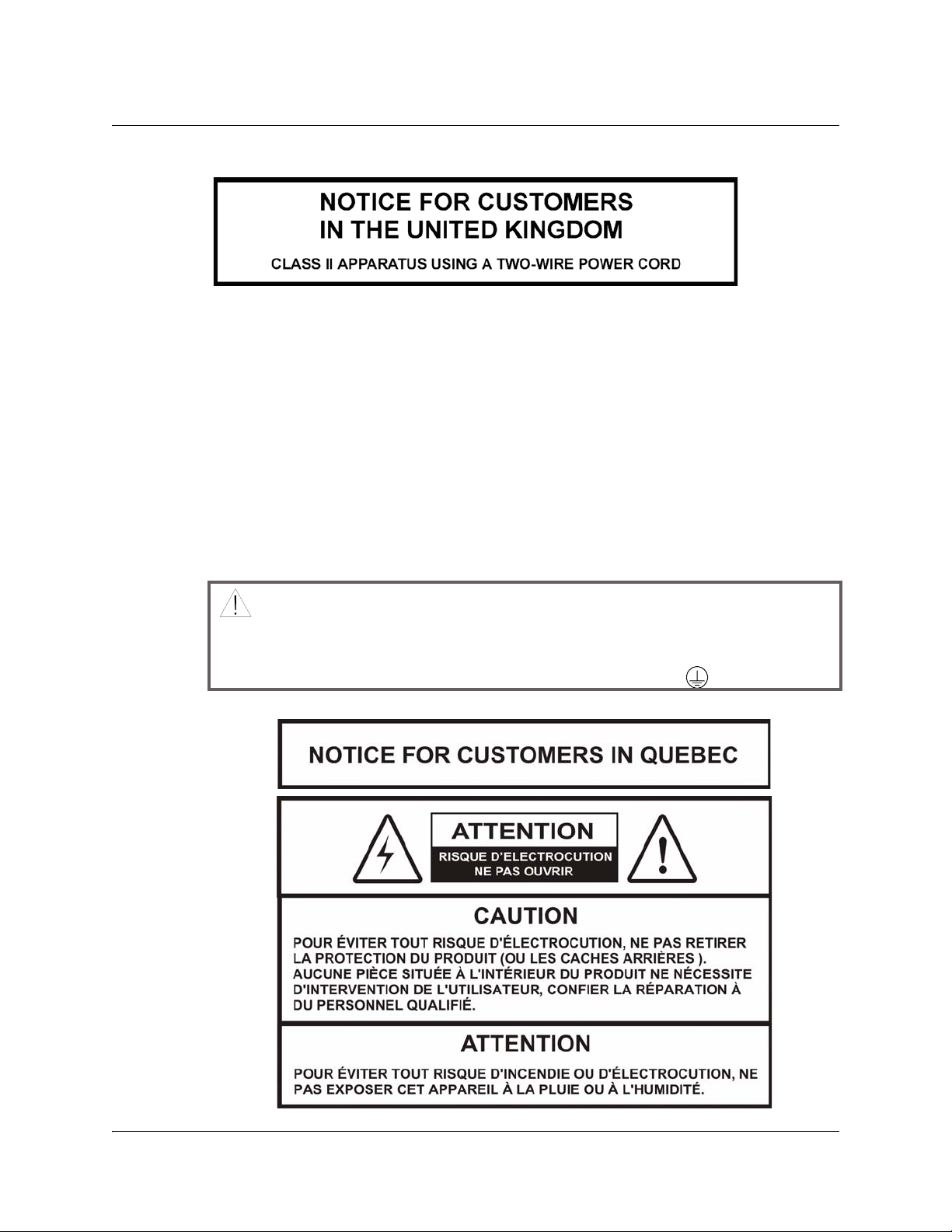
WARNING:
AC Mains Lead Connection (Important)
The wires in this mains lead are coloured in accordance with the following code:
•Blue: Neutral
•Brown: Live
As the colours of the wires in the mains lead of this apparatus may not correspond
with coloured markings identifying the terminal in your apparatus, proceed as
follows:
1. The wire which is coloured blue must be connected to the terminal which is
marked with the letter N or coloured black.
The wire which is coloured brown must be connected to the terminal which is
marked with the letter L or coloured red.
Do not connect the blue or brown wires to the earth terminal of a three-pin plug. Note:
The earth terminal is distinguished by its color (green, or green-yellow), or by being
marked with the letter E, or marked with the safety earth symbol ( ).
xii D9865 Satellite Receiver Installation and Operation Guide 4035197 Rev C
Page 13

Contents
Safety Precautions.......................................................................................................................................v
Safety Precautions (EU Market).................................................................................................................ix
Chapter 1 Quick Setup - Read Me First!
About the Video Standard...............................................................................................1-1
Quick Setup Instructions..................................................................................................1-2
Rear Panels Connections..................................................................................................1-4
Chapter 2 Introduction
D9865 Satellite Receiver ...................................................................................................2-2
Chapter 3 Front Panel Operation
About the Front Panel ......................................................................................................3-2
Common Interface Modules............................................................................................3-5
Remote Control Functions...............................................................................................3-6
Chapter 4 Setup and Monitoring via On-Screen Display
Main Menu.........................................................................................................................4-3
Channel List without EPG...............................................................................................4-6
Introduction to the EPG ...................................................................................................4-7
Setting Timers..................................................................................................................4-10
Setting Up Your Favorite Channels..............................................................................4-13
Setting Up One Button Channel Change.....................................................................4-16
Setup Menu......................................................................................................................4-17
Setting up Tuning / Preset ............................................................................................4-18
Setting up the Preset / LNB ..........................................................................................4-21
Setting up LNB ................................................................................................................4-23
Setting Up the Satellite Dish..........................................................................................4-26
Setting up the Video .......................................................................................................4-33
Setting up Subtitles .........................................................................................................4-40
Setting up Audio.............................................................................................................4-42
Advanced Setup ..............................................................................................................4-44
Setting up Advanced User Settings..............................................................................4-45
Changing the Lock Level Password.............................................................................4-48
Setting up POV Mode.....................................................................................................4-50
Network Setup.................................................................................................................4-52
Configuring Noise Cutoffs ............................................................................................4-63
Setting up Alarms and Warnings .................................................................................4-67
Viewing Downloads .......................................................................................................4-69
4035197 Rev C D9865 Satellite Receiver Installation and Operation Guide xiii
Page 14

Contents, Continued
Setting Bootable Application Selection........................................................................4-70
System Information ........................................................................................................4-71
Viewing the Version Information.................................................................................4-72
Viewing Hardware Information...................................................................................4-73
Viewing Installed Options.............................................................................................4-74
Viewing Service Information.........................................................................................4-75
Viewing Channel Information ......................................................................................4-76
Viewing DVB-CI Information .......................................................................................4-77
Viewing Device Status Information .............................................................................4-79
Viewing the Active Alarm and Warning Messages...................................................4-80
Viewing the RF Status ....................................................................................................4-82
Viewing Advanced RF Diagnostics..............................................................................4-84
Viewing ADP Status.......................................................................................................4-85
Chapter 5 Setup and Monitoring via Web GUI
Logging on to the Web GUI.............................................................................................5-3
Web GUI - Summary Screen............................................................................................5-4
Links....................................................................................................................................5-6
D9865 Web GUI Environment ........................................................................................5-7
Tuning Setup .....................................................................................................................5-9
Setting Up Dish Pointing ...............................................................................................5-12
Setting up SI Receive Parameters .................................................................................5-16
Setting up Muting Threshold Controls........................................................................5-18
Setting up the Tuning Presets/LNB.............................................................................5-21
Setting up LNB Presets...................................................................................................5-23
Viewing Input Status......................................................................................................5-25
Setting the Channel Information ..................................................................................5-26
Configuring the Common Interface (CI) Information...............................................5-28
Viewing the PSI Tables...................................................................................................5-32
Viewing PSI Frequency Information............................................................................5-33
Viewing the PSI Channels..............................................................................................5-34
Setting up the Video .......................................................................................................5-35
Configuring Captions.....................................................................................................5-37
Setting up Subtitles .........................................................................................................5-38
Setting up Audio.............................................................................................................5-41
Viewing System Information ........................................................................................5-43
Viewing Features/Licenses ...........................................................................................5-44
Setting Up IP Information..............................................................................................5-45
Setting Up IP Routing.....................................................................................................5-46
xiv D9865 Satellite Receiver Installation and Operation Guide 4035197 Rev C
Page 15

Contents, Continued
Setting Up SNMP and Trap Destinations....................................................................5-48
Configuring Time/Clock Information.........................................................................5-50
Configuring Favorites and Reminders ........................................................................5-51
Viewing the Alarm/Warning Status............................................................................5-53
Setting Up Alarms and Warnings ................................................................................5-54
Viewing the Alarm/Warning History.........................................................................5-56
Viewing Version Information .......................................................................................5-57
Setting Up Import/Export Information.......................................................................5-59
Viewing the Backup/Restore History..........................................................................5-61
Managing D9865 Web GUI Accounts ..........................................................................5-62
Configuring Lock Level Settings ..................................................................................5-65
Viewing Contact Information .......................................................................................5-67
Viewing Diagnostic Logs...............................................................................................5-68
Viewing the Usage Counters.........................................................................................5-69
Performing Service Actions...........................................................................................5-71
Chapter 6 Customer Information
Product Support................................................................................................................6-2
Returning Products...........................................................................................................6-4
Chapter 7 Service and Maintenance
Messages.............................................................................................................................7-2
Troubleshooting ..............................................................................................................7-19
Appendix A Technical Specifications
Receiver Specifications....................................................................................................A-2
LNB Requirements...........................................................................................................A-3
DVB-S Eb/No (C/N) Ratio.............................................................................................A-4
DVB-S2 Error Rate Performance ES/No (C/N) Ratio................................................A-5
Video Output....................................................................................................................A-6
Audio Outputs..................................................................................................................A-7
Power .................................................................................................................................A-8
General...............................................................................................................................A-8
Appendix B Default Settings
Factory Default Settings.................................................................................................. B-2
Appendix C Lock Levels
D9865 Satellite Receiver Lock Levels ............................................................................C-2
4035197 Rev C D9865 Satellite Receiver Installation and Operation Guide xv
Page 16

Contents, Continued
Appendix D Compliance
Applicable Notices and Disclaimer...............................................................................D-1
xvi D9865 Satellite Receiver Installation and Operation Guide 4035197 Rev C
Page 17

Quick Setup - Read Me First!
About the Video Standard
The Video Standard used to operate the receiver is preset at the factory to either
NTSC (525-line), or PAL (625-line). Changing the Video Standard is normally
required only when operating the receiver in a network or jurisdiction that uses the
alternate Video Standard, and/or when new (or different) subscriber services are
made available. Changing the Video Standard or resetting the receiver to the
default factory settings may cause TV video to display improperly.
Satellite Receiver Startup
1. Check your installation:
Check that your receiver is correctly installed and connected to the satellite LNB
antenna, to other A/V equipment (as required) and to AC power.
Important! This product plugs into a socket outlet. A socket outlet must be near
this product, and must be easily accessible. This product may not have a main
power switch; the power cord serves this purpose.
The product has a power switch (located on the rear panel). It may be used to
turn off the receiver to conserve energy.
Chapter 1
2. The application code version and APP appears on the receiver front panel while
it is powering up. It takes about 60 seconds for the receiver to completely power
up. Once the receiver has completely powered up, a flashing “.” appears on the
front panel.
3. Turning on the receiver: Press the DISPLAY button on the Remote Control or
press the DISPLAY button on the receiver front panel.
4. A “No signal” message is displayed on the TV monitor. To set up your receiver
for your network to receive your authorized programs, refer to Quick Setup
Instructions, on page 1-2.
4035197 Rev C D9865 Satellite Receiver Installation and Operation Guide 1-1
Page 18

Quick Setup Instructions
The following instructions are for use with the Remote Control.
1. Display the MAIN MENU by pressing MENU.
2. Press the
3. Move to the Tuning / Preset menu and press OK.
4. Enter or select the following parameters on this menu from your service
provider. Refer to About the Front Panel, on page 3-2 for instructions on the use
of the arrow buttons.
•Enter the Modulation Type (DVB-S, DVB-S2).
•Enter the Downlink Frequency (in GHz).
•Enter the Symbol Rate (in MS/s).
•Enter the NetId.
• Select LO Select (On, Off, Auto) when using a Ku-band dual LNB. This
controls the 22 kHz tone.
•Enter LO Freq 1 (in GHz) based on C or Ku-Band LNB operation (e.g., 9.75 for
Ku-Band, 5.150 for C-Band).
•Enter LO Freq 2 (in GHz). Use this when using a Ku-band dual LNB. LO Freq
2 > LO Freq 1.
•Enter the Crossover frequency when using a Ku-band dual LNB.
•Enter the LNB Power. Turn on if using the receiver to power the LNB.
• Select DiSEqC (if required). This allows control of the satellite dish motor.
Note: LNB Power must be on to use DiSEqC functions.
• Select the LNB port for the DiSEqC Switch (if used).
button to move to the Setup Menu and press OK.
Note: The LNB power alarm will be on if LNB power is on for use with a
DisEqC switch, but external power is also used.
Receivers with Factory Pre-configured Presets
If the receiver has been factory pre-configured with presets, press the yellow button
to go to the Preset / LNB Setup menu to view the presets and select the one for your
network.
Note: You need to press OK to view the parameters and Name of the preset.
Once you have selected your network preset by scrolling through the presets in the
Preset field, press the blue button to Activate the displayed preset as the current
preset.
Go to Step 5.
1-2 D9865 Satellite Receiver Installation and Operation Guide 4035197 Rev C
Page 19

Quick Setup Instructions, Continued
5. The “Acquiring Network” message is displayed until the “Acquisition Status”
message appears. Press OK to continue or press EXIT to cancel and return to the
menu. If the dish is aligned, Signal Lock will display “Lock” to the right.
Press EXIT to go to video.
If the dish is not aligned, the “Acquisition Failed” message is displayed. Select
OK to save the settings. Go to the Dish Setup menu to align the dish.
4035197 Rev C D9865 Satellite Receiver Installation and Operation Guide 1-3
Page 20
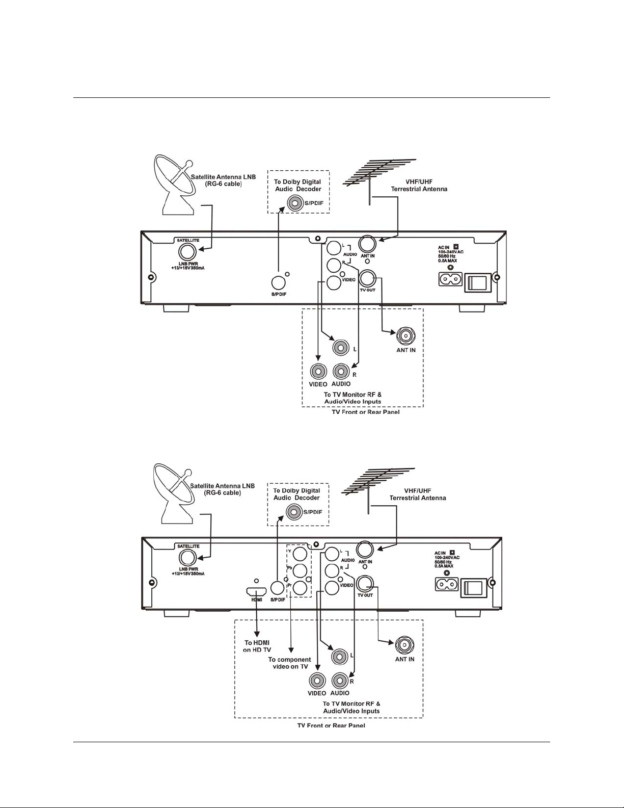
Rear Panels Connections
D9865B Satellite Receiver
D9865H Satellite Receiver
1-4 D9865 Satellite Receiver Installation and Operation Guide 4035197 Rev C
Page 21
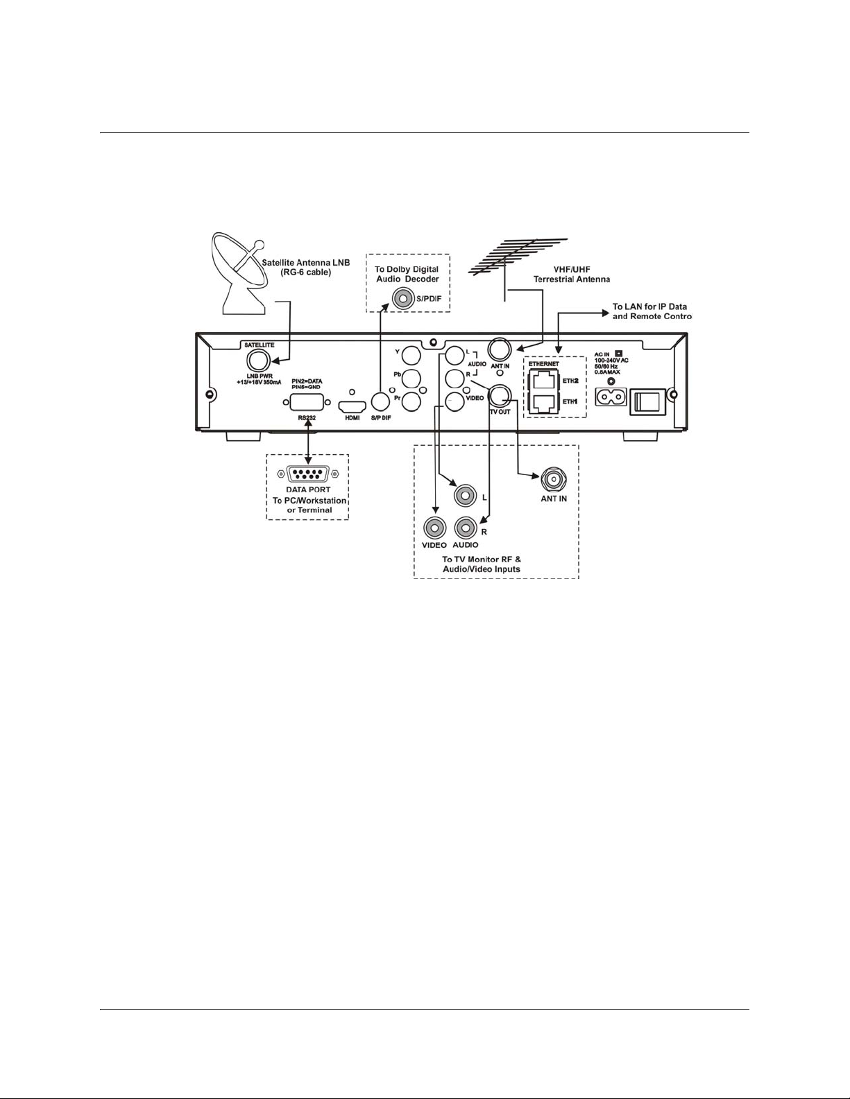
Rear Panels Connections, Continued
D9865D Satellite Receiver
Note: Only ETH1 Ethernet port is currently available.
4035197 Rev C D9865 Satellite Receiver Installation and Operation Guide 1-5
Page 22

1-6 D9865 Satellite Receiver Installation and Operation Guide 4035197 Rev C
Page 23

Overview
Introduction
This chapter is a general introduction to the Cisco® D9865 Satellite Receiver. It
describes the most common applications and interfaces of the receiver.
In This Chapter
This chapter contains the following topics.
Chapter 2
Introduction
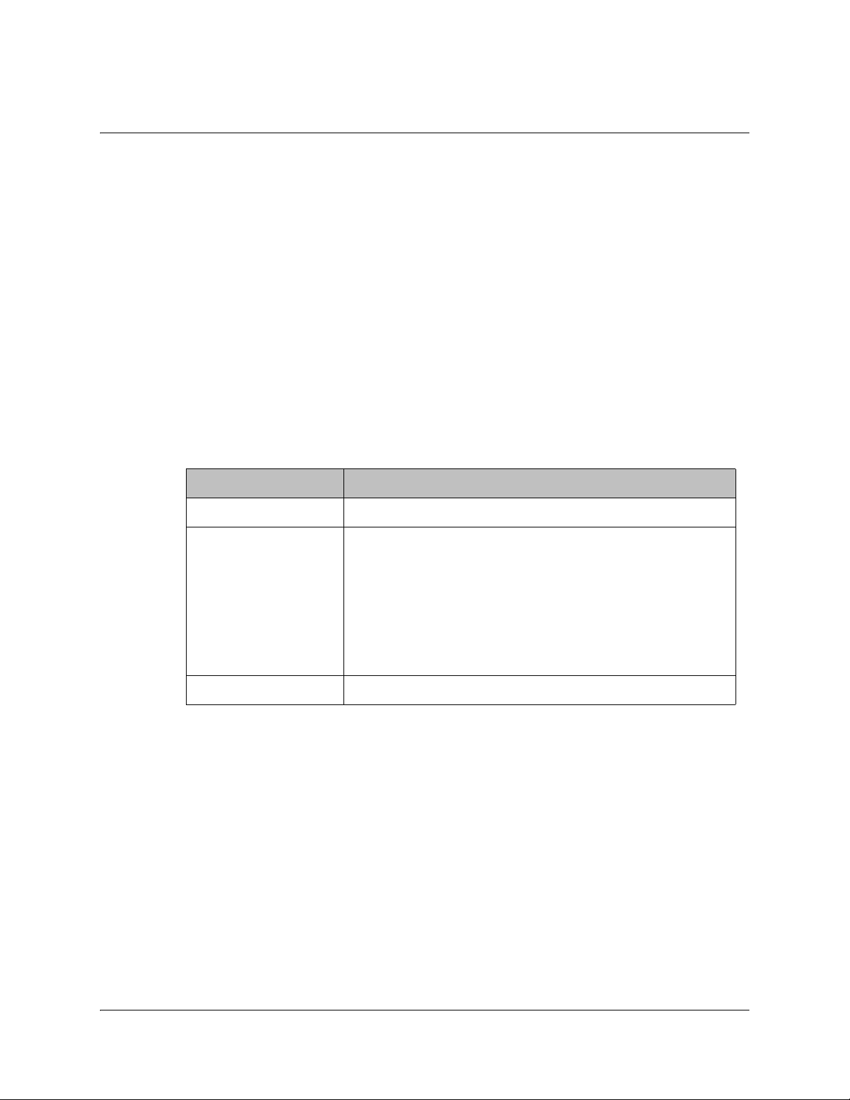
Topic See Page
D9865 Satellite Receiver 2-2
4035197 Rev C D9865 Satellite Receiver Installation and Operation Guide 2-1
Page 24

D9865 Satellite Receiver
General Description
The Cisco D9865 Satellite Receiver is designed for satellite content distribution and
it targets the broadcast, business TV, private networks, and SMATV environment.
The receiver offers the ability to receive digitally encrypted video, audio, VBI, and
data. It provides a cost-effective, variable-rate solution to transition existing DVBS/MPEG-2 services to DVB-S2/MPEG-4. Additional features include IP data and
RS-232 utility data (D9865D only).
The unit is set up via the on-screen display menu, using a handheld infrared remote
control, or navigation keys on the front panel of the receiver. The unit can also be set
up and monitored using the embedded Web interface. User-editable presets are
provided for quick re-tuning to other broadcasts. The receiver also supports SNMP
control via the Ethernet port as an option.
Free-to-air Reception
This receiver is capable of receiving a DVB/MPEG compliant free-to-air broadcast.
Secured Broadcast Reception
Supporting the PowerVu conditional access with DES or DVB descrambling, or
with DVB Conditional Access Module (CAM) based DVB CA systems, this receiver
can be used to receive secured corporate communication of video, audio, and data
broadcast. It can also be used for secured delivery of TV programming to hotels,
MDUs, homes, and commercial establishments such as restaurants and stores.
Data Outputs (D9865D only)
Data outputs can be used for distribution of electronic documents, such as price lists
and video files. Utility data (RS-232) can be used for smaller file transfer at a slower
speed. DVB MPE IP data via an Ethernet interface allows for connection to a local
area network for larger file transfer or communication with multiple network
clients.
MIB Browser
A MIB Browser is a type of SNMP manager, which can be used to communicate
with SNMP agents. It is a tool for reading and writing to controls and status objects
defined by the MIB.
Note: A MIB file is included in the delivery from Cisco for the D9865 Satellite
Receiver to support 3rd party SNMP managers.
2-2 D9865 Satellite Receiver Installation and Operation Guide 4035197 Rev C
Page 25

D9865 Satellite Receiver, Continued
Key Features
The D9865 receiver provides the following key features:
• DVB-S QPSK, DVB-S2 QPSK/8PSK demodulation
• Variable QPSK symbol rates from 1 to 45 MS/s for DVB-S and 1 to 31 MS/s for
DVB-S2
®
•PowerVu
• CAM interface hardware for DVB CAM-based descrambling
• 4:2:0 High Definition (HD) MPEG-2 and MPEG-4 AVC decoding
• 4:2:0 Standard Definition (SD) MPEG-2 and MPEG-4 AVC decoding
• 4:2:0 NTSC and PAL (B/G/I/D/M/N) video decoding
•MPEG, Dolby
• DVB Subtitling and DVB VBI (WST, WSS, VPS)
• One unbalanced stereo pair of audio outputs
• Line 21 closed caption and V-chip support
• Fingerprint trigger
• Service replacement
• Field upgradeable software and security
• Front panel 4-digit LED for channel display
• On-screen display menu for setup and status
• User-editable preset configurations
• Low Speed Data
• SNMP traps support for alarms and warnings
• MIB Browser support, used to manage SNMP requests
• Web browser interface for easy setup, control and monitoring
• Browse channels using the Electronic Program Guide (EPG)
conditional access with DES and DVB descrambling
®
Digital Plus and HE-AAC audio decoding
Optional Features
The following features are available options:
• HDMI and component video outputs for HDTV (D9865H and D9865D only)
• Support HDCP on HDMI port (D9865H and D9865D only)
• Dual Ethernet 10/100BaseT for IP data and SNMP control (D9865D only)
• Multiprotocol Encapsulation (MPE) data support with static Unicast routes and
Multicast forwarding (D9865D only)
4035197 Rev C D9865 Satellite Receiver Installation and Operation Guide 2-3
Page 26

2-4 D9865 Satellite Receiver Installation and Operation Guide 4035197 Rev C
Page 27
Overview
Introduction
This chapter describes how to set up the D9865 Satellite Receiver using the front
panel keys and display. This information is primarily applicable for standalone
operation.
In This Chapter
This chapter contains the following topics.
Chapter 3
Front Panel Operation
Topic See Page
About the Front Panel 3-2
Common Interface Modules 3-5
Remote Control Functions 3-6
4035197 Rev C D9865 Satellite Receiver Installation and Operation Guide 3-1
Page 28
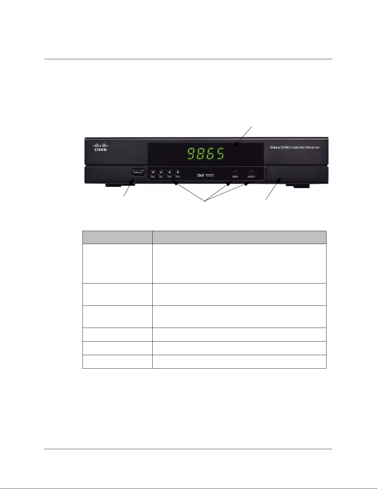
About the Front Panel
CI Slot
Navigation Selection
Display Button
LCD Panel
Introduction
The front panel of your satellite receiver provides controls for enabling the
receiver’s video output, and for interfacing with the remote control. MUTE,
SIGNAL and MENU LEDs are also provided. Some remote control buttons are
duplicated on the front panel for activating and navigating menus.
Button Function
DISPLAY • Enables the video display output.
• When the video display is enabled, the channel
number is displayed on the front panel. When switched
off, a “.” flashes.
MENU • Enters Menu mode or returns to video.
• Returns to previous menu.
SELECT • Selects menus.
• Enters or exits edit mode.
• In Menu mode, used to navigate menus.
• In Video mode, used for volume up/down.
• In Video mode, used for channel up/down.
3-2 D9865 Satellite Receiver Installation and Operation Guide 4035197 Rev C
Page 29
About the Front Panel, Continued
To change a setting on a menu using the front panel:
1. Use the
2. For numeric options, you can:
3. To access the menus at the bottom of the screen (for example, Save), navigate to
4. Press Menu to move to the previous menu.
Front Panel LEDs
The functions of the LEDs are described in the table below.
MUTE • On when sound is muted.
SIGNAL • On when receiver is synchronized with the incoming
buttons to move to the setting you want to change. Press the
Select button to select the setting.
•use the
• navigate to Keyboard using the
keyboard.
the appropriate selection using the
message is displayed at the bottom of the screen.
buttons to change the value one digit at a time, or
buttons to use an on-screen
buttons and press Select. A help
LED Function
digital signal and authorized for the current channel.
• Flashing when a signal has been found, but receiver is
not authorized for the current channel.
• Off when no signal has been found. For more
information about troubleshooting your satellite
receiver, see Troubleshooting, on page 7-19.
MENU • On when on-screen menus are displayed.
CI Slot
The CI Slot allows the use of CAM (Conditional Access Module) Smart Card to
decrypt purchased programming. For setup information, see Viewing DVB-CI
Information, on page 4-77 and Configuring the Common Interface (CI)
Information, on page 5-28. For a list of supported CAMs, refer to Common
Interface Modules, on page 3-5.
4035197 Rev C D9865 Satellite Receiver Installation and Operation Guide 3-3
Page 30

About the Front Panel, Continued
Keyboard Display
Press the MENU and SELECT buttons simultaneously on the Front Panel to display
a keyboard on the TV monitor. The keyboard allows alphabetical and numerical
character entry in menu fields using the front panel. Alternatively, press the red
button on the remote control.
Note: You must have a menu field selected (i.e., must be in edit mode) to display
the keyboard.
1. Use the arrow buttons to move along the keyboard.
2. Press OK to select a number or letter for each entry.
Setting the TV Video Format
The video format is set to the standard format for your country. Check with your
satellite or local service provider before changing this setting to ensure it is set
correctly. If you are instructed to change this setting for your TV set:
1. Press the SELECT and
2. Press SELECT and
panel (e.g., NTSC, PAL, etc).
3. Press
4. Press SELECT to save the setting and re-display the selected channel.
until you display your video format. Each change is viewable on-
screen.
Note: You must be in video mode (i.e., on-screen menus not displayed) to
perform this function on the receiver front panel.
Note: This function is not available through the remote control.
buttons on the receiver front panel at the same time.
again. The video format is displayed on the receiver front
3-4 D9865 Satellite Receiver Installation and Operation Guide 4035197 Rev C
Page 31
Common Interface Modules
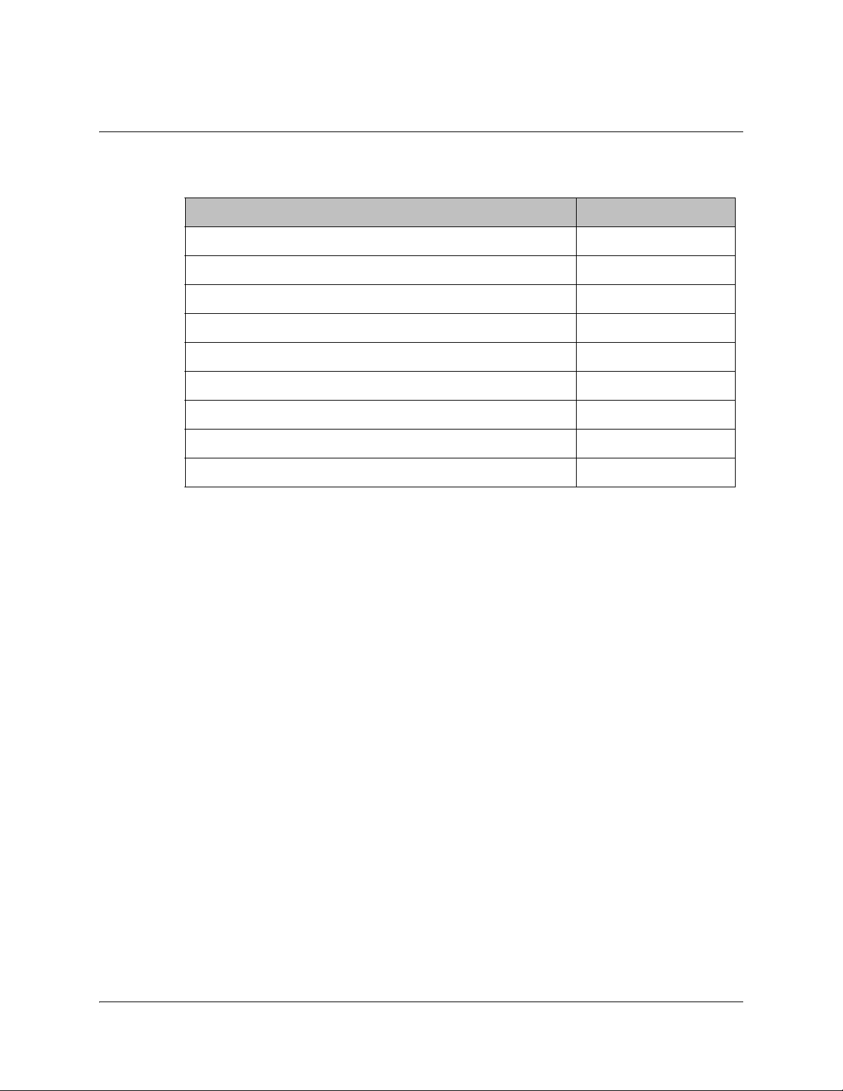
Only CAMs purchased from Cisco are currently supported. The following lists the
supported CAMs:
Common Interface Modules Part Number
Aston Professional CAM, for descrambling CONAX 4016669
Aston Consumer CAM for descrambling CONAX 4016670
CAM for descrambling CryptoWorks V9523361
Aston Professional CAM for descrambling Irdeto 4016671
Aston Consumer CAM for descrambling Irdeto 4016672
Aston Professional CAM for descrambling MediaGuard V9528197
Aston Consumer CAM for descrambling MediaGuard V9528198
Aston Professional CAM for descrambling Viaccess V9528199
Aston Consumer CAM for descrambling Viaccess V9528240
4035197 Rev C D9865 Satellite Receiver Installation and Operation Guide 3-5
Page 32

Remote Control Functions
The remote control is provided as a standard feature with the D9865 Satellite
Receiver. After unpacking your satellite receiver, check that you have the following
accessories (if ordered):
• One IR (Infra-Red) Remote Control transmitter (RCU)
• Two AAA size batteries for Remote control (not included for Argentina)
The Remote Control is used to control receiver functions. You can switch the video/
audio outputs on and off plus activate and navigate the on-screen menus. Some
remote control functions are duplicated on the front panel (see Front Panel LEDs,
on page 3-3).
Remote Control Button Function
DISPLAY • Enables the video/audio outputs.
0 to 9 • Enters channel numbers or information on
on-screen menus.
• Alphanumeric character entry for “Name”
field on the on-screen menus (similar to keys
on telephone keypad). If an entered value is
out of range or conflicts with another setting,
a pop-up message displays information
about the error.
00 (pressing 0 twice) – deletes a character at
the cursor location.
11 (pressing 1 twice) – adds a space at the
cursor location.
FAV • Displays Favorite screen where you can
view and set favorite channels.
LAST • Displays last channel.
MENU • Displays Main Menu.
• Exits edit mode in menus.
• Returns to video in video mode.
• Returns to previous menu.
3-6 D9865 Satellite Receiver Installation and Operation Guide 4035197 Rev C
Page 33

EPG • If the receiver is enabled to receive EPG
(Electronic Program Guide) data, an
interactive EPG guide will be displayed
when pressed. If not, a channel list menu and
video will be displayed.
• In Video mode, used to select channels.
• In Menu mode, used to move through onscreen menus.
• In Video mode, increases or decreases
volume.
• In Menu mode, used to move through onscreen menus.
• Selects menus (functions same as SELECT
button on front panel).
• Enters or exits edit mode.
CH+, CH- • Channel up/down.
VOL+, VOL- • Volume up/down.
EXIT •Exits from edit mode.
• Exits menus (returns to video).
• Mutes sound.
• Changes to uppercase letter mode.
• Page up when scrolling the on-screen
menus.
• Changes to lowercase letter mode.
• Page down when scrolling the on-screen
menus.
• Red – different on each menu. Aso
displays the soft keyboard.
• Green – different on each menu
• Yellow – different on each menu
• Blue – different on each menu
Setup • Displays the Setup Menu.
4035197 Rev C D9865 Satellite Receiver Installation and Operation Guide 3-7
Page 34

3-8 D9865 Satellite Receiver Installation and Operation Guide 4035197 Rev C
Page 35

Overview
In This Chapter
This chapter contains the following topics.
Chapter 4
Setup and Monitoring via On-Screen Display
Topic See Page
Main Menu 4-3
Channel List without EPG 4-6
Introduction to the EPG 4-7
Setting Timers 4-10
Setting Up Your Favorite Channels 4-13
Setting Up One Button Channel Change 4-16
Setup Menu 4-17
Setting up Tuning / Preset 4-18
Setting up the Preset / LNB 4-21
Setting up LNB 4-23
Setting Up the Satellite Dish 4-26
Setting up the Video 4-33
Setting up Subtitles 4-40
Setting up Audio 4-42
Advanced Setup 4-44
Setting up Advanced User Settings 4-45
Changing the Lock Level Password 4-48
Setting up POV Mode 4-50
Network Setup 4-52
Configuring Noise Cutoffs 4-63
Setting up Alarms and Warnings 4-67
Viewing Downloads 4-69
Setting Bootable Application Selection 4-70
4035197 Rev C D9865 Satellite Receiver Installation and Operation Guide 4-1
Page 36

Topic See Page
System Information 4-71
Viewing the Version Information 4-72
Viewing Hardware Information 4-73
Viewing Installed Options 4-74
Viewing Service Information 4-75
Viewing Channel Information 4-76
Viewing DVB-CI Information 4-77
Viewing Device Status Information 4-79
Viewing the RF Status 4-82
Viewing Advanced RF Diagnostics 4-84
Viewing ADP Status 4-85
4-2 D9865 Satellite Receiver Installation and Operation Guide 4035197 Rev C
Page 37

Main Menu
This section contains the information you need to set up your Satellite Receiver
using the on-screen display menus. Before you begin using the receiver, you may
need to change the current settings to suit your operating requirements.
To display the Main Menu, press the MENU button on the remote control or
receiver front panel.
If the D9865 Satellite Receiver is enabled to receive Electronic Program Guide (EPG)
data, the following Main Menu screen appears.
As shown above, you can select the EPG, Timer, Favorite, One Button Channel
Change, or the Setup Menu.
• EPG - displays an interactive EPG guide with all the available subscriber
channels.
• Timer - Displays reminder timers set for upcoming programs.
• Favorite - Displays a list of favorite channels set by the user.
• One Button Channel Change - Ability to assign a channel to each of the colored
buttons at the bottom of the remote control.
• Setup Menu - provides access to menus to set up tuning, select and set up presets,
set up video, audio, and other advanced parameters, in addition to viewing the
receiver operating status.
4035197 Rev C D9865 Satellite Receiver Installation and Operation Guide 4-3
Page 38

Main Menu, Continued
If the receiver does not support EPG, the following Main Menu screen appears:
As shown above, you can select the Channel List, One Button Channel Change, or
the Setup Menu.
• Channel List – displays all the available subscriber channels. See an example of a
Channel List below.
• One Button Channel Change - provides ability to assign a channel to each of the
colored buttons at the bottom of the remote control.
• Setup Menu - provides access to menus to set up tuning, select and set up presets,
set up video, audio, and other advanced parameters, in addition to viewing the
receiver operating status.
4-4 D9865 Satellite Receiver Installation and Operation Guide 4035197 Rev C
Page 39

Main Menu, Continued
About using the on-screen menus
All screens or menus are accessed from the Main Menu. While viewing any
channel, you can display on-screen menus for viewing or changing the current
receiver setup. While in menus, you can change the current receiver settings, and/
or display other menus. Some menus contain status information, which is available
for viewing only and cannot be changed.
To change a setting on a menu using the remote control:
1. Use the
2. Press the OK button to select the setting.
3. For numeric options, you can use one of the following methods:
• enter the number directly using the numeric keypad on the remote control,
•use the
• press the red button (keyboard) to use an on-screen keyboard.
4. Press OK to save the setting and exit the menu. A help message is displayed at
the bottom of the screen.
5. Press MENU to move to the previous menu.
Note: The steps in this chapter are based on using the remote control. For more
information on changing a setting on a menu using the front panel controls, see
About the Front Panel, on page 3-2.
The On-Screen Buttons
The on-screen menus have the following common buttons:
buttons to move to the setting you want to change.
buttons to change the value one digit at a time, or
Button Description
Save Saves and applies the settings to the
receiver.
Exit Exits edit mode and menu. A message
prompts you to save or discard changes
before you exit the menu.
About the Current Channel
When you navigate to menus from a video channel, the information displayed is
associated with the current (video) channel. If no changes have been made to the
current setup, you are automatically returned to the same video channel when you
exit to video.
4035197 Rev C D9865 Satellite Receiver Installation and Operation Guide 4-5
Page 40

Channel List without EPG
If the receiver does not support EPG, you can access the Channel List from the Main
Menu.
To select a channel from the channel list:
1. From the Main Menu screen, select Channel List and press OK. The Channel
List displays all the available subscriber channels.
2. Select a channel from the channel list and press OK. This will tune to the
selected channel (top right) and the channel information is displayed in the
bottom right of the channel list:
Options Description
Channel Name Name of the current channel.
Channel Number Current channel number.
Last Act Preset Indicates the number of the last activated
CA Authorized Indicates whether the receiver is
preset.
authorized to receive the signal.
The channel lost screen will close when pressing OK.
4-6 D9865 Satellite Receiver Installation and Operation Guide 4035197 Rev C
Page 41
Introduction to the EPG
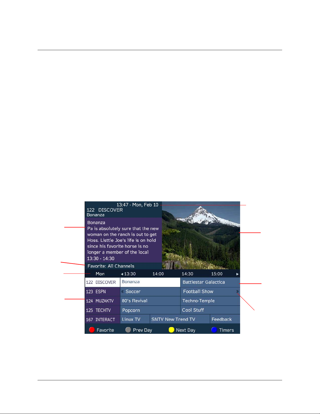
Channels
Program you are
watching is reduced
to fit in this area
Main Program
listing
Channel Banner
describes highlighted program
Current Favorite
profile
Date and Time of
the program
Current Date and Time
Program extends
Time beyond the grid
end time
What is EPG?
The Electronic Program Guide (EPG) is a convenient way to find out what is on
your TV and to view a list of upcoming programs. Lists of programs are available
for any date in the next 7 days depending on the network provider.
Features of the EPG
The following list provides an overview of the features of an EPG:
• With the browsing features, you can see what is on TV for a particular channel,
program channel, or program title.
• Instant program descriptions appear while using the browsing feature to view
detailed channel information.
• Timers help you keep track of upcoming programs by providing reminders on
the screen before the program starts.
• You can set up Favorite profiles for a quick browse of your favorite channels.
Browsing By Channel
From the Main Menu, select EPG and press OK. The EPG main screen is shown
below. The EPG screen enables you to browse by channel, which lists all the
available programs in order by time of day and date.
4035197 Rev C D9865 Satellite Receiver Installation and Operation Guide 4-7
Page 42
Introduction to the EPG, Continued
Parts of the Guide
The following list describes the parts of the guide.
• The program you are watching is reduced to fit in the upper right are of your
screen. The program remains there while you are using the main functions of the
guide.
• The current Information banner under the picture provides the current date, time
and channel.
• The Channel Banner provides a description for each program you highlight in the
main program list.
• The Main Program listing displays the programs that will be broadcast.
• Press the blue button (Timers) to view the list of timers set for upcoming
programs.
• Press the red button (Favorite) to view the list of Favorite profiles.
Browsing by a Different Date
You can view upcoming program information for up to 7 days in advance by
changing the day of the week you are browsing.
Press the yellow button (Next Day) or the green button (Prev Day) to change the
day of the week to view upcoming program information on the following day.
Press the green button (Prev Day) to view the program information.
Viewing Favorites
Press the red button (Favorite) to view a list of all the configured Favorite profiles.
For more information on setting up the favorite profiles, see Setting Up Your
Favorite Channels, on page 4-13.
4-8 D9865 Satellite Receiver Installation and Operation Guide 4035197 Rev C
Page 43
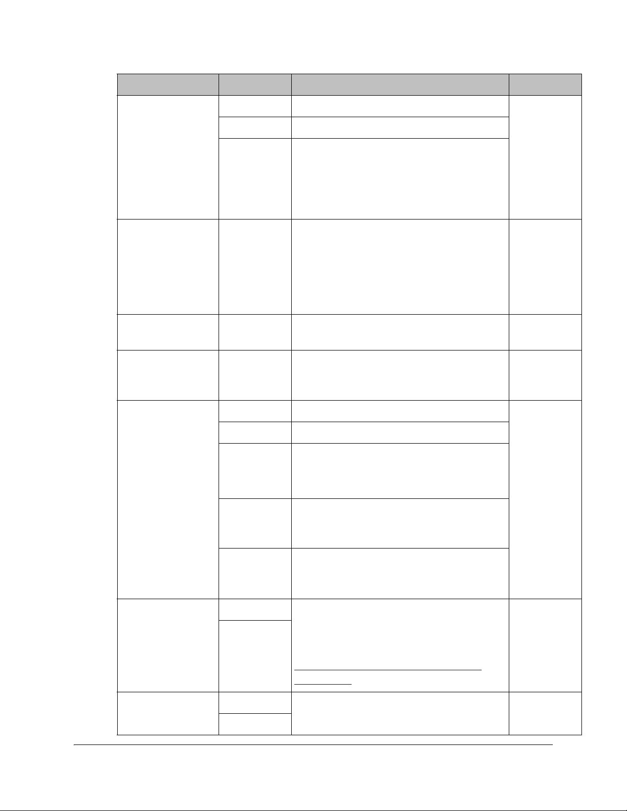
Introduction to the EPG, Continued
Program being
watched
Current program
name
Upcoming program
name
Press for more information on
the current program
Current
Channel
Number
Current time
Current Channel
Name
Time progress for
the current
program
Current Favorite
Profile
Start/End time
of program
Viewing Timers
Press the blue button (Timers) to view all the configured timer profiles.
For more information on setting up and maintaining timer profiles, see Setting
Timers, on page 4-10.
Changing Channels
As you change the channel while watching TV, a brief channel banner appears
along the bottom of the TV screen with the current time and channel information.
For program details, press the green button (Info). The Extended Info screen is
displayed, with additional program information. The following displays an
example of a channel banner:
4035197 Rev C D9865 Satellite Receiver Installation and Operation Guide 4-9
Page 44

Setting Timers
Setting a Reminder Timer From EPG
You can set up timers that will display a reminder on-screen when the configured
program is on.
Note: You cannot set a timer for a program that has already started.
Proceed as follows to set a reminder timer from EPG:
1. From the Main Menu screen, select EPG and press OK.
2. Select an upcoming program you want to set a reminder by scrolling through
the guide using the
screen is displayed with the channel name, information and program time.
buttons and then press OK. The Extended Info
3. If the program selected has already started, press Next
next time slot.
4. Press the green button (Set Timer). The Set Timer screen is displayed.
5. The following table describes the channel information and the timer options:
Channel/Timer
Information
Channel Number Number of the selected channel.
Description
to set a timer for the
4-10 D9865 Satellite Receiver Installation and Operation Guide 4035197 Rev C
Page 45

Channel/Timer
Seconds left
before the
program
starts
Description
Information
Channel Name Name of the selected channel.
Event Name Name of the selected program.
Day Day of the week the program will be on the selected
channel.
Start Time Start time of the selected program.
Frequency Set the frequency of the reminder: Once, Daily,
Weekly, or Weekdays.
6. Click the green button (Save) to save your timer settings.
Note: You can set a maximum of 50 timer profiles.
The following is an example of a reminder that appears on-screen:
Press OK to close the reminder window and tune to the specified channel.
Otherwise, press Exit to close the reminder window.
The clock symbol on the left hand side displays a countdown of seconds left
before the program starts and the reminder window closes.
4035197 Rev C D9865 Satellite Receiver Installation and Operation Guide 4-11
Page 46

Setting Timers, Continued
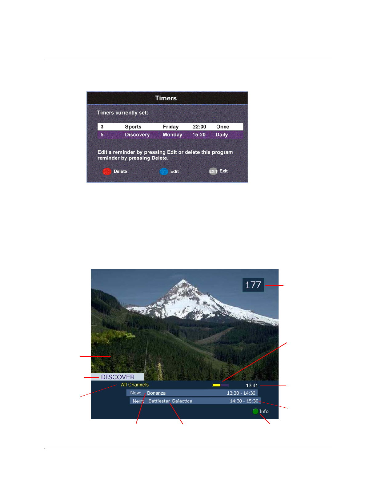
Editing a Timer Profile
1. From the Main Menu, select Timers and press OK. The Timers screen is
displayed.
2. From the Timers screen, scroll to the Timer profile you want to edit using the
buttons.
3. Select Edit or press the blue button (Edit). The Set Timer screen is displayed.
4. Make the necessary changes.
5. Press the green button (Save) to save the Timers list.
Deleting a Timer Profile
1. From the Main Menu, select Timers and press OK. The Timers screen is
displayed.
2. From the Timers screen, scroll to the Timer profile you want to delete using the
buttons.
3. Select Delete or press the red button (Delete). A warning message appears
confirming your deletion.
4. Press OK to confirm.
4-12 D9865 Satellite Receiver Installation and Operation Guide 4035197 Rev C
Page 47

Setting Up Your Favorite Channels
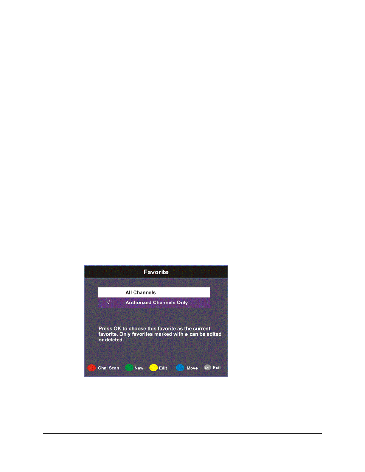
The Favorite screen displays a list of all the favorites configured in the D9865.
Favorites allow you to surf through the channels you have set up as your favorite
channels, skipping over other channels.
By default, All Channels (authorized and unauthorized channels) are displayed.
The Authorized Channels Only lists channels that are authorized by your uplink
provider. Setup is authorized only by doing a channel scan.
Adding a Favorite Profile
Proceed as follows to configure your favorites list:
1. From the Main Menu screen, select Favorite and press OK, or press FAV.
2. Press the green button (New) to create a new Favorites list.
4035197 Rev C D9865 Satellite Receiver Installation and Operation Guide 4-13
Page 48

Setting Up Your Favorite Channels, Continued
3. Select Favorite Name and press OK to edit the new favorite name. Enter the
name directly using the numeric keypad on the remote control or use the
buttons to change the letters/numbers one alphabet/digit at a time.
Alternatively, press the red button (Keyboard) to enter the name using an onscreen keyboard.
4. Select the Channel Mode and press OK to select the type of channels listed
below. Select All to list all the channels in the network. Select Authorized Only
to list all the channels that are authorized by your uplink provider only.
5. Scroll through the channel list using the
channels you want to your new favorites list on the right. A checkmark appears
to the left of the channel, indicating that the channel is in the favorites list.
6. Press the
button (Move) to move the selected channel up/down the list using
buttons. When you are done moving the channel, press the blue button (End
Move).
7. Press the green button (Save) to create and save the new Favorites list.
Editing a Favorite Profile
Note: You cannot edit All Channels or the authorized channels only.
1. From the Favorite screen, scroll to the Favorite profile you want to edit using the
buttons.
2. Press the yellow button (Edit). The Edit/Delete Custom Favorite screen is
displayed.
3. Select Edit or press the blue button (Edit). The Edit Favorite List screen is
displayed.
4. Make the necessary changes.
buttons and press OK to add the
button to edit the selected channels on the right. Press the blue
5. Press the green button (Save) to save the Favorites list.
Deleting a Favorite Profile
Note: Only Favorites that are marked with a circle can be deleted.
1. From the Favorite screen, scroll to the Favorite profile you want to delete using
buttons.
the
2. Press the yellow button (Edit). The Edit/Delete Custom Favorite screen is
displayed.
3. Select Delete or press the red button (Delete). A warning message appears
confirming your deletion.
4-14 D9865 Satellite Receiver Installation and Operation Guide 4035197 Rev C
Page 49

Setting Up Your Favorite Channels, Continued
4. Press OK to confirm.
Performing a Channel Scan
The Channel Scan function scans through all the available channels and updates the
Authorized Channels Only list. For more information on your authorized channels,
contact your uplink service provider.
Proceed as follows to perform a channel scan:
1. From the Favorite screen, press the red button (Chnl Scan). A warning message
appears confirming the channel scan. It can take several minutes, depending on
the size of the network.
2. Press OK. The Authorized Channels Only list is updated.
4035197 Rev C D9865 Satellite Receiver Installation and Operation Guide 4-15
Page 50

Setting Up One Button Channel Change
To Set Up One Button Channel Change
Proceed as follows to set up one button channel change:
From the Main Menu, select One Button Channel Change and press OK.
The Button colors (Red, Green, Yellow, and Blue) corresponds to the colored
buttons at the bottom of the remote control (see below).
Each color can be assigned to a channel as a shortcut for a quick channel change. For
example, if you assign the red button to channel 1, pressing the red button while
watching a different channel at anytime will automatically tune the TV channel to 1.
Note: You can only use the one button channel change if the screen is displaying
video only. The one button channel change does not work if EPG, Channel Banner
or on-screen menus are displayed.
4-16 D9865 Satellite Receiver Installation and Operation Guide 4035197 Rev C
Page 51

Setup Menu
The Setup Menu is used to set up the receiver.
The available sub-menus are as follows:
• Tuning / Preset
•Dish Setup
•Video Setup
• Audio Setup
• Advanced
•Info
From this menu, you can display and change Presets, and set up the LNB.
This menu provides a graphical aid for dish pointing/alignment.
From this menu, you can set the TV channel to display video on your TV, the
video format (e.g., NTSC or PAL), TV aspect ratio, and subtitling control.
From this menu, you can set the Stereo/Mono selection and select digital audio
preferences.
From this menu, you can access other sub-menus for control and display of
features such as Lock Level, Conditional Access, the Ethernet port and
Diagnostics, and available services to control code downloads.
From this menu, you can access other sub-menus to display information about
the receiver software, and hardware versions, view device status and other
signal-related parameters.
4035197 Rev C D9865 Satellite Receiver Installation and Operation Guide 4-17
Page 52

Setting up Tuning / Preset
To Set Up Tuning/Preset Parameters
The Tuning/Preset menu is used to display and configure the current settings.
Proceed as follows to set up the tuning/preset:
1. From the Setup Menu screen, select Tuning / Preset and press OK.
2. The following table describes each of the available options:
Selection Options Description Default
Modulation Type DVB-S Enter the modulation scheme. DVB-S2
DVB-S2
Downlink (Freq) Enter
number
Symbol Rate 1.0 to 45.0
1.0 to 31.0
NetId Enter
number
For C-Band:
Downlink Freq = LO Freq - L-Band Freq.
For Ku-Band:
Downlink Freq = LO Freq + L-Band Freq.
Range for DVB-S in MS/s.
Range for DVB-S2 in MS/s.
Obtain the number from your service
provider.
12.3
30.0
1
4-18 D9865 Satellite Receiver Installation and Operation Guide 4035197 Rev C
Page 53
Selection Options Description Default
LO Select
(Sets a 22 kHz tone
On Switches 22 kHz tone on. Off
Off Switches 22 kHz tone off.
for Ku-band dual
LNB)
Auto Sets 22 kHz tone to automatic.
LO Freq 1 Enter
number
LO Freq 2 Enter
number
Crossover Enter
number
If Downlink Freq < Crossover, use LO
Freq 1. The 22 kHz tone is Off.
If Downlink Freq > Crossover, use LO
Freq 2. The 22 kHz tone is On.
If C-band application, set to 5.15 GHz
(default).
If Ku-band single LNB, enter LO Freq. and
set LO Freq 2 and Crossover to 0.0.
If Ku-band dual LNB, enter LO Freq 1, LO
Freq 2 and Crossover.
Enter if Ku-band dual LNB application.
LO Freq 2 > LO Freq 1.
Enter if Ku-Band dual LNB application.
Determines if LO Freq 1 or LO Freq 2 is
used for tuning.
10.75 GHz
0.0
0.0
LNB Power
(For more
18-H For H polarization (18V). 18-H
13-V For V polarization (13V).
information, see
LNB Power
Settings, on
page 4-25.)
Off Use for external LNB power.
Note: LNB power must be on if DiSEqC is
required.
H-NIT Initially applies the horizontal
polarization voltage, and then follows the
polarization based on the NIT.
V-NIT Initially applies the vertical polarization
voltage, and then follows the polarization
based on the NIT.
DiSEqC Enable Enables or disables Digital Satellite
Disable
Equipment Control. This must be enabled
to control the DiSEqC switch. LNB Power
Disable
must be on to use this setting. Refer to
http://www.eutelsat.com/satellites/
4_5_5.html for more information.
DiSEqC Switch Off Selects a port on the LNB switch (if used). Off
A to P
4035197 Rev C D9865 Satellite Receiver Installation and Operation Guide 4-19
Page 54

Selection Options Description Default
Signal Lock Indicates signal synchronization status.
Signal Quality Indicates the quality of the received signal,
associated with the Bit Error Rate, in the
range from 0 to 100.
Signal Level Indicates the strength of the received
signal in the range from 0 to 100.
Note: If you enter an invalid frequency setting or a setting that does not correspond
to the selection, a pop-up message such as “Input value out of range" is displayed.
3. Press the green button (Save) to save and apply the settings to the receiver.
4-20 D9865 Satellite Receiver Installation and Operation Guide 4035197 Rev C
Page 55
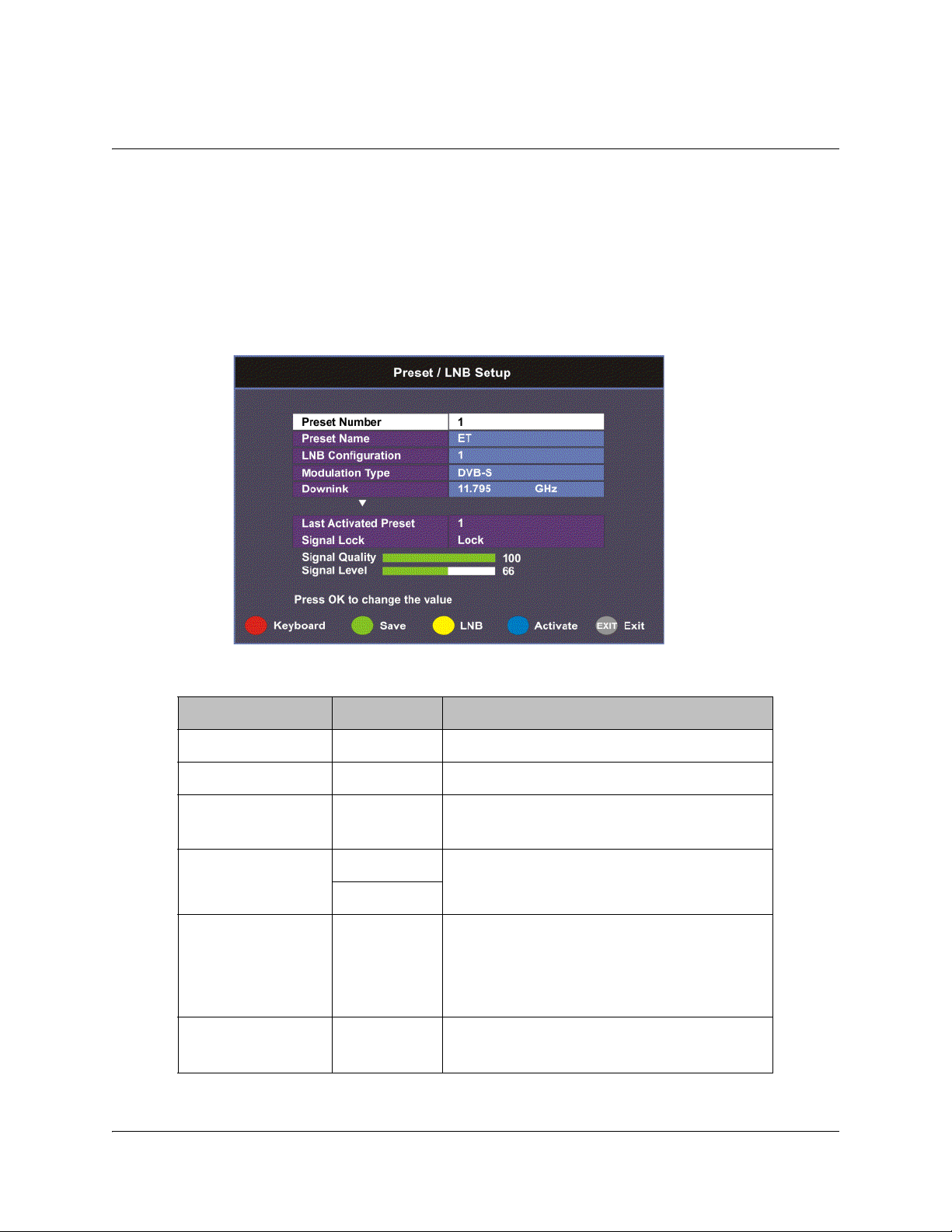
Setting up the Preset / LNB
To Set Up Preset/LNB Parameters
The Preset/LNB Setup sub-menu allows you to select or configure up to 64 network
presets. Your receiver may be shipped pre-configured with a number of network
presets. You can configure the network preset to use one of 10 LNB configurations.
Proceed as follows to set up the preset/LNB settings:
1. From the Tuning / Preset screen, press the yellow button (Preset) to set up the
Preset/LNB.
2. The following table describes each of the available options:
Selection Options Description
Preset Number 1 to 64 Enter or select the preset number.
Preset Name Enter name Set the preset network name.
LNB
Configuration
Modulation Type DVB-S Select the modulation scheme.
Downlink (Freq) Enter
Symbol Rate 1.0 to 45.0
1 to 10 Enter or select the LNB configuration.
DVB-S2
For C-Band,
number
1.0 to 31.0
Downlink Freq = LO Freq - L-band Freq.
For Ku-Band,
Downlink Freq = LO Freq + L-band Freq.
Range for DVB-S in MS/s.
Range for DVB-S2 in MS/s.
4035197 Rev C D9865 Satellite Receiver Installation and Operation Guide 4-21
Page 56

Selection Options Description
NetId Enter
Last Activated
Preset
Signal Lock Indicates signal synchronization status.
Signal Level Indicates the relative strength of the
3. Press the green button (Save) to save and apply the settings to the receiver.
Selecting the Active Preset
To change the displayed preset to the Active preset or to select a different preset as
the active preset:
1. From the Tuning/Preset screen, press the yellow button (Preset).
2. Enter the preset in the Preset field that you want to activate. Enter the number
directly using the numeric keypad on the remote control or use the
buttons to change the number one digit at a time. Alternatively, press the red
button (keyboard) to enter the preset using an on-screen keyboard.
3. Select Activate (blue button) to choose the preset. This will activate the currently
displayed preset as the active preset.
You will be prompted to accept the new preset and warned that service
interruption will occur.
number
Obtain the number from your service
provider.
Indicates the number of the last activated
preset.
received signal, in the range from 0 to 100.
4. Select OK to proceed or EXIT to cancel the operation.
5. Press MENU to go to the previous menu.
Note: It will take up to 30 seconds for signal acquisition to occur. It can take longer
if the symbol rates are low.
Editing Network Presets
You can edit or pre-configure any one of 64 presets without affecting the operation
of the receiver.
To save or change a network preset:
1. Enter a Preset Number and a name directly to below the Preset Number. Follow
the editing rules for the keys when entering characters in the Name field.
2. Enter the appropriate settings as described in the preceding table. Ensure that
the LNB selection corresponds to the correct downlink frequency.
3. Press OK to save the preset.
4-22 D9865 Satellite Receiver Installation and Operation Guide 4035197 Rev C
Page 57

Setting up LNB
To Set Up LNB Parameters
Proceed as follows to set up the LNB:
1. From the Preset/LNB Setup menu, press the yellow button (LNB) to set up the
LNB.
Note: You can configure up to 10 LNB presets.
2. The following table describes each of the options:
Selection Options Description
LNB Configuration 1 to 10 Number identifying the current preset LNB
configuration.
LNB Power
(For more
information, see LNB
Power Settings, on
page 4-25.)
18-H For H polarization.
13-V For V polarization.
Off Use for external LNB power.
Note: LNB power must be on if DiSEqC is
required.
H-NIT Initially applies the horizontal polarization
voltage, and then follows the polarization based
on the NIT.
V-NIT Initially applies the vertical polarization voltage,
and then follows the polarization based on the
NIT.
4035197 Rev C D9865 Satellite Receiver Installation and Operation Guide 4-23
Page 58
Selection Options Description
LO Freq1 Enter
number
If C-band application, set to 5.15 GHz (default).
If Ku-band single LNB, enter LO Freq. and set
LO Freq 2 and Crossover to 0.0.
If Ku-band dual LNB, enter LO Freq 1, LO Freq
2 and Crossover.
LO Freq2 Enter
number
Crossover Enter
number
Enter if Ku-band dual LNB application. LO Freq
2 > LO Freq 1.
Enter if Ku-Band dual LNB application. Used to
determine if LO Freq 1 or LO Freq 2 is used for
tuning.
LO Select
(Sets a 22 kHz tone
for Ku-band dual
LNB)
Off Switches 22 kHz tone off.
On Switches 22 kHz tone on.
Auto Sets 22 kHz tone to automatic.
If Downlink Freq < Crossover use LO1. The 22
kHz tone is Off.
If Downlink Freq > Crossover use LO2. The 22
kHz tone is On.
DiSEqC Enable Enables or disables Digital Satellite Equipment
Disable
Control. This must be enabled to control the
DiSEqC switch. LNB Power must be on to use
this setting. Refer to http://www.eutelsat.com/
satellites/4_5_5.html for more information.
DiSEqC Switch Off Selects a port on the LNB switch (if used).
A to P
Note: If you enter an invalid frequency setting or a setting that does not correspond
to the selection, a pop-up message such as “Input value out of range" is displayed.
3. Press the green button (Save) to save your settings.
4-24 D9865 Satellite Receiver Installation and Operation Guide 4035197 Rev C
Page 59
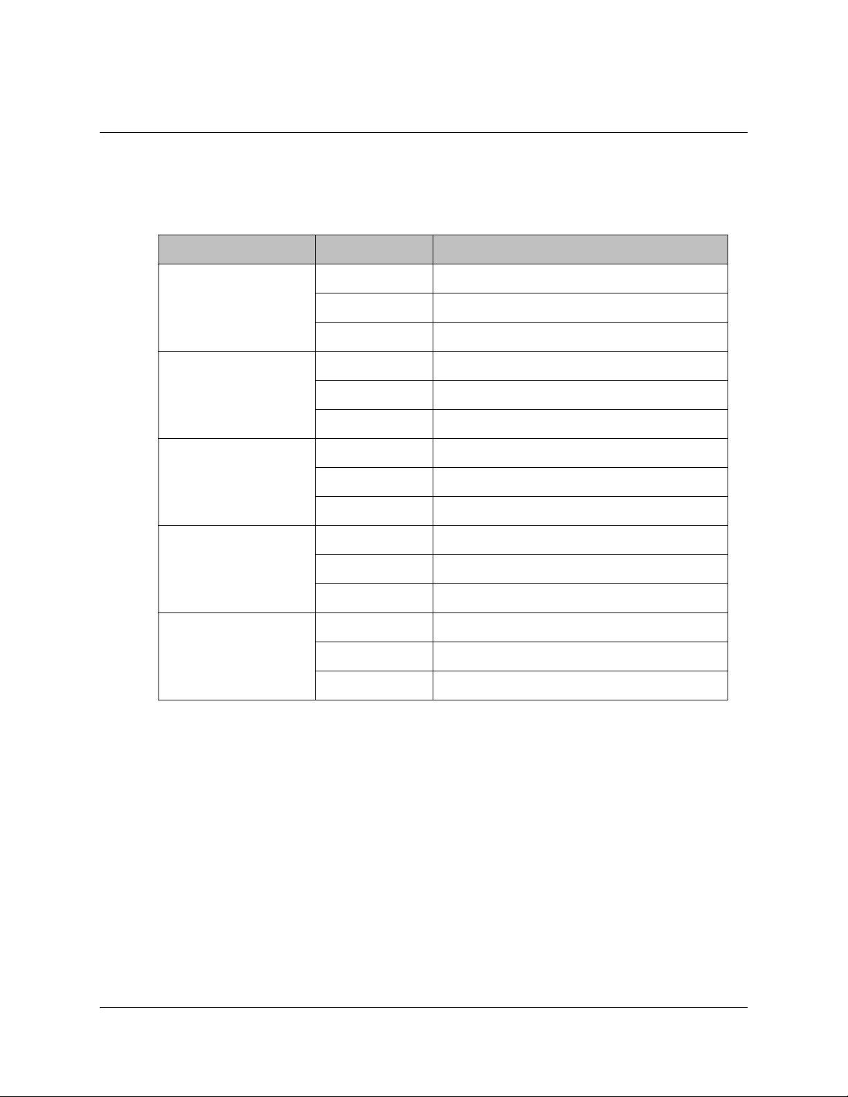
Setting up LNB, Continued
LNB Power Settings
The following table displays the LNB Power settings:
LNB Power Setting NIT Contains Output LNB Voltage
Off Not received Off
18-H Not received 18 volts
13-V Not received 13 volts
H Off
V Off
H 18 volts
V 18 volts
H 13 volts
V 13 volts
H-NIT Not received 18 volts
H 18 volts
V 13 volts
V-NIT Not received 13 volts
H 18 volts
V 13 volts
4035197 Rev C D9865 Satellite Receiver Installation and Operation Guide 4-25
Page 60

Setting Up the Satellite Dish
To Set Up the Dish
The Dish Setup menu provides graphical assistance for dish positioning. This menu
can be set to two modes: User Mode (default) or Installer Mode. The User mode
allows you to select from stored Satellite Numbers, which are stored satellite
locations, as stored in the dish motor, but does not provide any dish control.
Proceed as follows to set up the dish:
1. From the Setup Menu, select Dish Setup and press OK. By default, the Dish
Setup screen is displayed in User mode.
2. The table at the top displays the current configurations.
3. The following table describes each of the options in User mode:
Selection Options Description
Satellite Number 1 to 255 Number identifying the saved satellite
location as defined by the dish motor
manufacturer.
User Action None No action is performed.
Goto Satellite Moves the dish to the selected pre-stored
satellite position. Satellite positions are stored
in the dish motor, if supported, not in the
receiver.
4-26 D9865 Satellite Receiver Installation and Operation Guide 4035197 Rev C
Page 61

Setting Up the Satellite Dish, Continued
4. Press the yellow button to switch between User and Installer modes. The
Installer mode is for Installers only.
5. The following table describes each of the available options for the Installer
mode:
Selection Options Description
Satellite Number 1 to 255 Number identifying the saved satellite
location as defined by the dish motor
manufacturer.
Absolute Position 0.0 to 75.0 Position of the satellite in degrees.
4035197 Rev C D9865 Satellite Receiver Installation and Operation Guide 4-27
Page 62
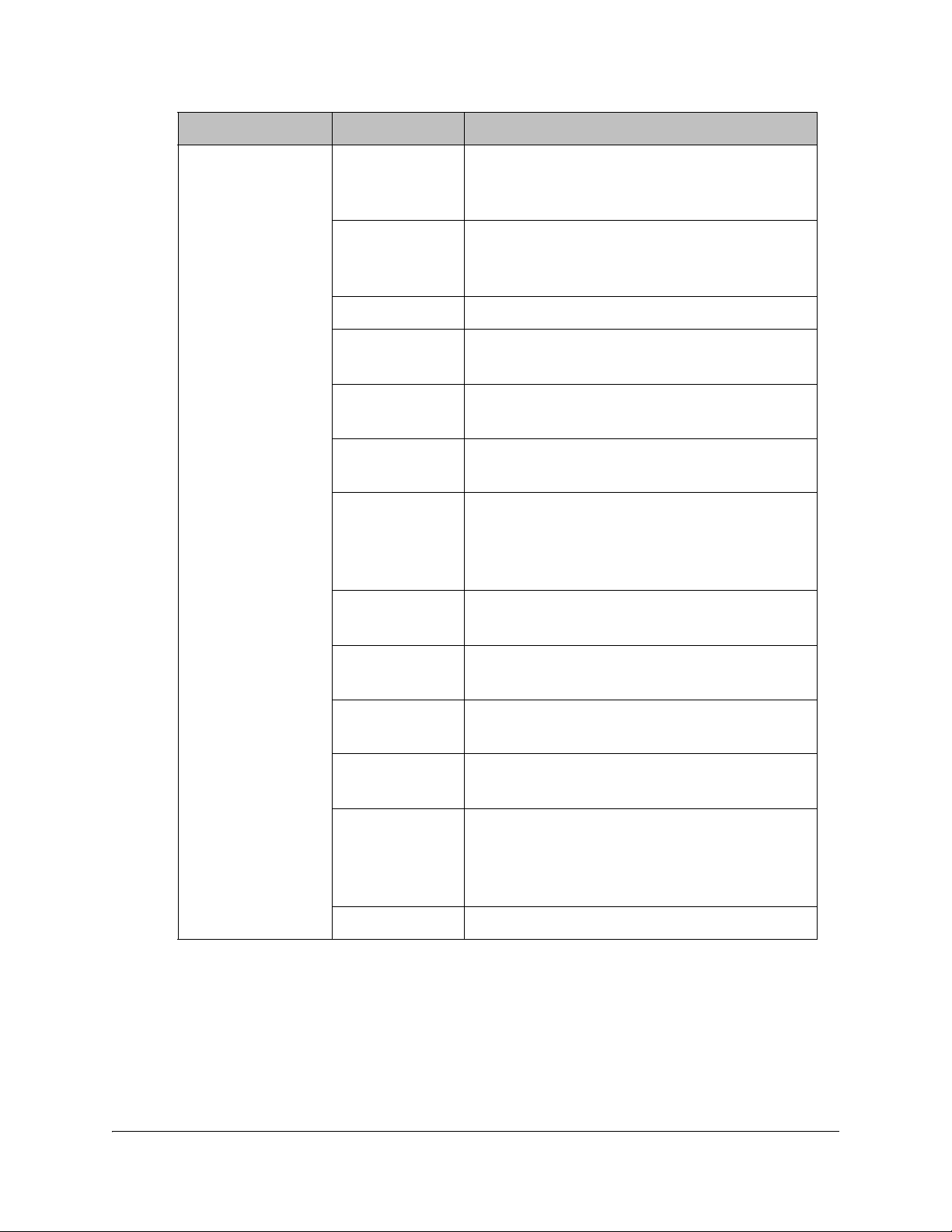
Selection Options Description
Installer Action Continuous
West
Movement
Continuous
East Movement
Stop Move Stops movement of the dish.
Goto Absolute
Position West
Goto Absolute
Position East
Goto Reference Moves the dish to a reference defined by the
Goto Satellite Moves the dish to the selected pre-stored
Store Satellite Stores the current dish position as a Satellite
Moves the dish west until it reaches its limit.
Ensure that the dish can move to its limit
without any obstructions.
Moves the dish east until it reaches its limit.
Ensure that the dish can move to its limit
without any obstructions.
Moves the dish to the Absolute west position
set above.
Moves the dish to the Absolute east position
set above.
dish motor manufacturer.
satellite position. Satellite positions are stored
in the dish motor, if supported, not in the
receiver.
Number, if supported by the dish motor.
Clear Limits Clears the dish east and west limits stored in
the dish motor.
Store East
Limits
Store West
Limits
Calculate
Position
Stores the current position as the east limit in
the dish motor.
Stores the current position as the west limit in
the dish motor.
Updates the position of the dish according to
the current position. For more information,
refer to the dish manual provided by the dish
manufacturer.
None No action is performed.
4-28 D9865 Satellite Receiver Installation and Operation Guide 4035197 Rev C
Page 63
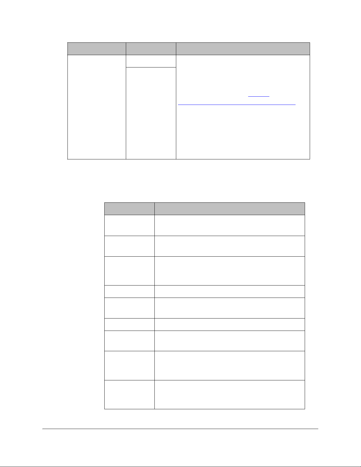
Selection Options Description
DiSEqC Enable Enables or disables Digital Satellite
Disable
Equipment Satellite Control.
Note: This must be enabled to control the
DiSEqC switch. LNB Power must be on to
use this setting. Refer to http://
www.eutelsat.com/satellites/4_5_5.html for
more information.
Before you can adjust the satellite position
using the Adjust Dish Position screen or a
signal tone, ensure that the LNB Power and
DiSEqC (in the Tuning/Preset screen) are
enabled.
6. Press the blue button (Do Action) to save and apply the settings to the receiver
until the next reboot.
7. The following table describes the view-only information on the Dish Setup
screen:
Parameter Description
Modulation Indicates the modulation type for the received
signal.
LDPC BER Indicates the bit rate of the input stream of the
LDPC error correcting stage (DVB-S2 only).
Mode Indicates whether the current dish setup mode is
Installer or User. The mode can be changed by
pressing the yellow button.
NW Name Displays the network name.
PV BER Indicates the PV (Post-Viterbi) BER for the received
signal (DVB-S).
PER Indicates the current PER (Packet Error Rate).
DiSEqC Status Indicates whether the DiSEqC is enabled or
disabled.
Signal Quality Indicates the quality of the received signal,
associated with the Bit Error Rate, in the range
from 0 to 100.
Signal Level Displays the relative strength of the received RF
input signal. It is displayed in the range from 0 to
100.
4035197 Rev C D9865 Satellite Receiver Installation and Operation Guide 4-29
Page 64

Parameter Description
Signal Lock Indicates whether the receiver is synchronized with
the received RF signal.
Adjusting the Satellite Position in Installer Mode
Note: To adjust the satellite position, the DiSEqC must be set to Enable.
1. On the Dish Setup screen, press the yellow button (Installer) to select Installer
mode.
2. Ensure the DiSEqC is set to Enable and then press the green button (Adj Dish).
3. Press the red or yellow button for fine west and east dish adjustment. Press the
green or blue button for coarse east and west dish adjustment.
Changing the Satellite Position in User Mode
To select a new satellite position on the Dish Setup menu:
1. Use the
2. Enter the pre-stored satellite number you want to use in the range from 1 to 255,
and press OK.
3. Press
4. Press
selected satellite position.
5. Press MENU to move to the previous menu, or EXIT to go to video.
buttons to move to Satellite Number and press OK.
to move down to User Action and press OK.
to choose Goto Satellite and press OK. The receiver is now tuned to the
4-30 D9865 Satellite Receiver Installation and Operation Guide 4035197 Rev C
Page 65

Setting Up the Satellite Dish, Continued
Adjusting the Satellite position using Signal Tones
Dish alignment can be done using the audible signal adjustment tone. The
characteristics of the signal tone are shown in the table below. Align the dish to
achieve signal lock and then best signal quality.
Note: The signal adjustment tone automatically outputs as PCM audio type only,
regardless of the Digital Audio Preference set in Audio Setup.
Signal Lock/Quality Tone
No Signal Lock Slow repeating tone.
Signal Lock Steady tone.
Signal Lock +
increasing Signal
Quality
Provided the RF cable is connected between the satellite receiver and the LNB,
Signal level displays a low number (typically less than 40). As the receiver achieves
Signal Lock, the Signal Level increases, and the tone changes from a slow repeating
beep to a steady tone. Once Signal Lock is obtained, align the dish to increase the
Signal Quality to the best possible value (up to a maximum of 10).
Signal Level and Signal Quality
The Signal Level and Signal Quality of the incoming signal are displayed both
numerically and graphically using bar graphs.
The Signal Level is associated with the RF input signal level. The Signal Level
display is continuously updated to indicate the relative strength of the received RF
input signal. It is displayed in the range from 0 to 100. Signal Level is displayed on
the Tuning / Preset and Dish Setup menus both numerically and graphically.
The Signal Quality (displayed in the range from 0 to 100) is associated with the Bit
Error Rate, and is a measure of the signal quality. Signal Quality is displayed both
numerically and graphically on the Dish Setup menu. To obtain the best signal
quality, adjust the dish position to obtain the highest Signal level and Signal
Quality possible.
Steady tone increasing in pitch.
Temporary, solar-related electromagnetic disturbances occur every year during the
spring and autumn months. These disturbances usually persist for several minutes
a day for approximately one week at this time. Your service provider can advise
you about channels that may be adversely affected.
To verify your satellite LNB antenna installation or improve signal reception, refer
to your antenna equipment installation manual, or contact your local service
provider.
4035197 Rev C D9865 Satellite Receiver Installation and Operation Guide 4-31
Page 66

Setting Up the Satellite Dish, Continued
Signal Lock
The Signal Lock status is continuously updated to indicate whether the receiver is
synchronized with the received satellite RF signal. Signal Lock status is displayed
on the Preset / LNB Setup and Dish Setup menus.
If the receiver is able to synchronize to a carrier frequency and an MPEG stream is
present, Signal Lock displays Lock and the Signal LED on the receiver front panel
is on. If no carrier is detected, Signal Lock displays No Lock and the Signal LED is
off.
4-32 D9865 Satellite Receiver Installation and Operation Guide 4035197 Rev C
Page 67

Setting up the Video
Setting up the Video
The video format is set to the standard format for your country. If you attempt to
change the format of the source video signal, a warning message appears, to inform
you that if the fields are incorrectly configured, the display may not be viewable.
Check with your satellite or local service provider before changing the video
settings to ensure it is set correctly. Press OK to continue with the edit. Otherwise,
select Cancel.
Note: If an error was made when changing the video settings, you can set the TV
video format using the front panel. For more information, see Setting the TV Video
Format, on page 3-4.
Proceed as follows to set up the video information.
1. From the Setup Menu screen, select Video Setup and click OK.
2. The following table describes each of the options in the Video Setup screen.
Selection Options Description Default
HD Video Output Auto Receiver automatically detects correct HD
video format.
HD 1080i Sets the HD output video format.
HD 720p
4035197 Rev C D9865 Satellite Receiver Installation and Operation Guide 4-33
Auto
Page 68

Selection Options Description Default
SD Video Output Auto Receiver automatically detects correct SD
video format.
PAL-B/G, PAL-
For 625-line systems.
D, PAL-I
PAL-M 525-line format for Brazil.
PAL-N (AR) 625-line format for Argentina.
NTSC, NTSC-J For 525-line systems.
TV Channel 3 or 4 for NTSC
Sets TV channel for video display. 3 or 21,
21-69 for PAL
TV Aspect Ratio 4:3, 16:9 The aspect ratio of the intended TV
system.
Aspect Ratio
Convert
None This is the conversion that the receiver will
Auto
Auto AFD
16:9 L/B
4:3 P/B
perform on the incoming signal for the
picture to be displayed correctly (i.e., to
correspond to the aspect ratio of your TV)
on your TV, based on your selection.
For the actual conversion performed, refer
to Actual Conversion Table, on page 4-35.
Depends
on TV
modulator
installed
depending
on TV
modulator
installed.
4:3
None
14:9
4:3 CCO
16:9 SCALE
Closed Caption Auto This is the mode of closed-captioning to
SA Custom
EIA 708
use. if there are multiple in the stream.
Note: SA Custom is not supported when
telecine video coding is enabled.
Type 3
Type 4 SA
Type 4 ATSC
Reserved
DVB 157
Stream Aspect
Ratio
4:3, 16:9 This indicates the aspect ratio of the
incoming signal. This is read-only.
Auto
4-34 D9865 Satellite Receiver Installation and Operation Guide 4035197 Rev C
Page 69

Selection Options Description Default
Actual Conversion This is the type of (aspect ratio) conversion
Actual Conversion Table
The following table displays the actual conversion performed by the receiver
according to your TV Aspect Ratio selection and the affect on the picture displayed
on the TV screen.
the receiver will perform based on what
you have selected. This is read-only.
Stream TV
Aspect
Ratio
Aspect
Ratio
Conversion
Actual
Conversion
Description Image
4:3 4:3 None None Normal Picture
4:3 4:3 Auto None No conversion
4:3 4:3 16:9 L/B None Conversion is not possible.
Normal picture.
4:3 4:3 4:3 CCO None Conversion is not possible.
Normal picture.
4:3 4:3 4:3 P/B None Conversion is not possible.
Normal picture.
4:3 4:3 14:9 None Conversion is not possible.
Normal picture.
4:3 4:3 16:9 SCALE None Conversion is not possible.
Normal picture.
4:3 16:9 None None Picture is short & fat.
4:3 16:9 Auto 4:3 P/B Uses 4:3 P/B.
4035197 Rev C D9865 Satellite Receiver Installation and Operation Guide 4-35
Page 70

Stream TV
Aspect
Ratio
Aspect
Ratio
Conversion
Actual
Conversion
Description Image
4:3 16:9 4:3 P/B 4:3 P/B 4:3 picture is centered in a
pillar-style box.
4:3 16:9 14:9 14:9 Compromises some up-
sampling. Some black bars
and cropping are visible.
4:3 16:9 16:9 SCALE 16:9 SCALE Vertically up-samples the
centre of the 4:3 picture and
crops the top and bottom of
the screen.
16:9 16:9 None None Normal
16:9 16:9 Auto None No conversion. Normal
picture.
16:9 16:9 16:9 L/B None Conversion is not possible.
Normal picture.
16:9 16:9 4:3 CCO None Conversion is not possible.
Normal picture.
16:9 16:9 4:3 P/B None Conversion is not possible.
Normal picture.
16:9 16:9 14:9 None Conversion is not possible.
Normal picture.
16:9 16:9 16:9 SCALE None Conversion is not possible.
Normal picture.
16:9 4:3 None None Picture appears tall and thin.
4-36 D9865 Satellite Receiver Installation and Operation Guide 4035197 Rev C
Page 71

Stream TV
Aspect
Ratio
Aspect
Ratio
Conversion
Actual
Conversion
Description Image
4:3 16:9 16:9 L/B None Conversion is not possible.
Picture appears short and fat.
4:3 16:9 4:3 CCO None Conversion is not possible.
Picture appears short and fat.
16:9 4:3 16:9 L/B 16:9 L/B Vertically down-samples the
picture and applies black
bars at the top & bottom of
the screen.
16:9 4:3 4:3 CCO 4:3 CCO Horizontally up-samples the
centre portion of the picture
to fill the 720.
16:9 4:3 4:3 P/B None Conversion is not possible.
Picture appears tall and thin.
16:9 4:3 14:9 14:9 Compromises some up-
sampling. Some black bars
and some cropping are
visible.
16:9 4:3 16:9 SCALE None Conversion is not possible.
Picture appears tall and thin.
4035197 Rev C D9865 Satellite Receiver Installation and Operation Guide 4-37
Page 72

Setting up the Video, Continued
Video Output Restrictions
The following table describes the nature of the Video Outputs given the source
video stream and selections that can be made by the user. The D9865 does not
provide video format conversion.
Source
Video
Format
SD-NTSC
(60Hz)
SD-PAL
(50Hz)
User
Selected
SD Format
Auto or
NTSC
PAL (50 Hz) Any Mismatch Mismatch
Auto or
PAL
NTSC Any Mismatch Mismatch
User
Selected
HD Format
Auto 1080i 60Hz NTSC
1080i 1080i 60Hz NTSC
720p 720p 30Hz NTSC
Auto 1080i 50Hz PAL
1080i 10801 50Hz PAL
720p 720p 25Hz PAL
Component &
HDMI
CVBS & TV-Out
1080i 60Hz Auto or
NTSC
PAL Any Mismatch Mismatch
1080i 50Hz Auto or
PAL
NTSC Any Mismatch Mismatch
4-38 D9865 Satellite Receiver Installation and Operation Guide 4035197 Rev C
Auto 1080i 60Hz NTSC
1080i 1080i 60Hz NTSC
720p 720p 30Hz NTSC
Auto 1080i 50Hz PAL
1080i 1080i 50Hz PAL
720p 720p 25Hz PAL
Page 73

Source
Video
Format
User
Selected
SD Format
User
Selected
HD Format
Component &
HDMI
CVBS & TV-Out
720p 30Hz Auto or
Auto 720p 30Hz NTSC
NTSC
1080i 1080i 60Hz NTSC
720p 720p 30Hz NTSC
PAL Any Mismatch Mismatch
720p 25Hz Auto or
Auto 720p 25Hz PAL
PAL
1080i 10801 50Hz PAL
720p 720p 25Hz PAL
NTSC Any Mismatch Mismatch
Video formats that require a frame rate change from the original source stream are
blocked by a “Video Format Mismatch” banner and the video output is muted.
4035197 Rev C D9865 Satellite Receiver Installation and Operation Guide 4-39
Page 74
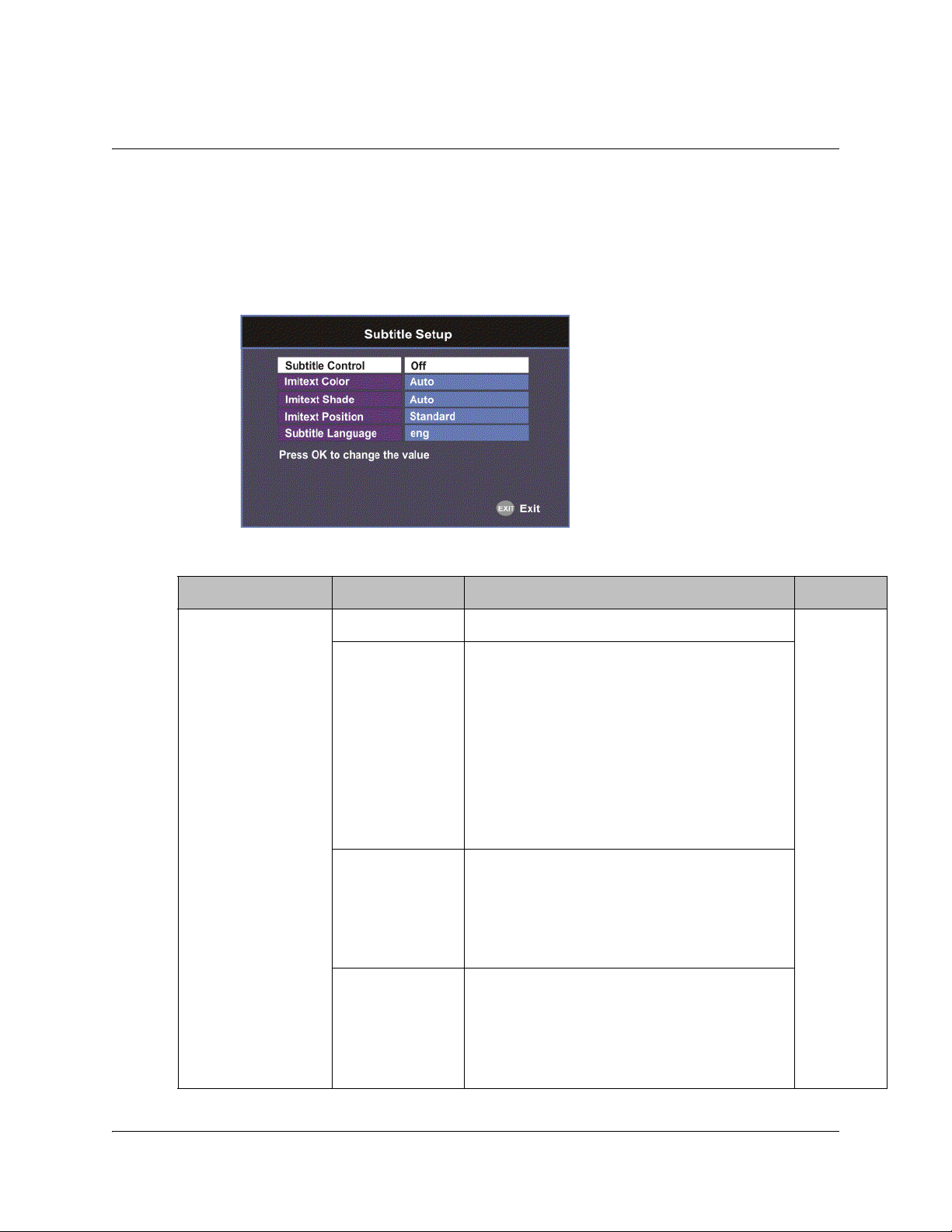
Setting up Subtitles
Setting up Subtitles
The Subtitle Setup screen allows you to configure the type of subtitling (i.e., DVB or
Imitext displayed by the receiver, and how the receiver displays subtitling on TV.
Proceed as follows to set up subtitling:
1. From the Video Setup screen, press the yellow button (Subtitle).
2. The following table describes each of the options on the Subtitle Setup screen:
Selection Options Description Default
Subtitle Control Off No subtitles are displayed. Off
On Functions as an “Auto” setting. DVB
subtitles are displayed when only DVB
subtitles are transmitted on the channel,
and likewise, Imitext subtitles are
displayed when only Imitext subtitles are
transmitted on the channel. When both
DVB and Imitext subtitles are available on
the same channel, only DVB subtitles will
be displayed.
Imitext Displays only Imitext subtitles. For
example, if Imitext is selected, but both
DVB and Imitext subtitles are being
transmitted on the same channel, only
Imitext subtitles will be displayed.
DVB Displays only DVB subtitles. For example,
if DVB is selected, but both DVB and
Imitext subtitles are being transmitted on
the same channel, only DVB subtitles will
be displayed.
4-40 D9865 Satellite Receiver Installation and Operation Guide 4035197 Rev C
Page 75
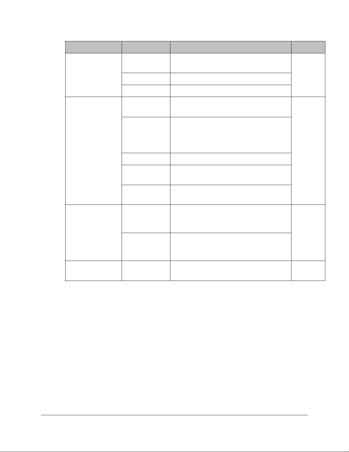
Selection Options Description Default
Imitext Color (text
color)
Auto Displays text in the color transmitted by
the subtitling equipment.
Yellow Displays text in yellow.
White Displays text in white.
Imitext Shade
(background color)
Auto Displays background in same shade
transmitted by the subtitling equipment.
Shadow Applies an outline to the right side of each
text character. No background box is
applied to subtitles, i.e., text is visible
directly on top of video.
Opaque Applies a black box to each text character.
Semi Applies a semi-transparent box to subtitle
text.
None No shadow or outline is applied to subtitle
text.
Imitext Position Standard Subtitles appear on screen in same
position as output from other PowerVu
receivers.
Auto
Auto
Standard
Extended Subtitles are positioned on screen
Subtitle Language Available
languages
according to the Imitext (extended)
specification.
Select from any one of the available
languages.
eng
(English)
4035197 Rev C D9865 Satellite Receiver Installation and Operation Guide 4-41
Page 76

Setting up Audio
Setting up the Audio
Proceed as follows to select the audio source.
1. From the Setup Menu screen, select Audio Setup and click OK.
2. The following table describes each of the options:
Selection Options Description Default
Stereo/Mono Stereo Left and right channels are output on L
and R respectively.
Mixed Left and right channels are combined and
output on both L and R.
L-MONO Left channel is output on L and R.
R-MONO Right channel is output on L and R.
DRC Mode RF Mode This setting is normally used for analog
cable modulators, when limited dynamic
range is desired.
Line Mode Setting used when full dynamic range is
allowed.
Digital Audio
Preference
PMT Audio Source None Select the PMT Audio Source for the audio
PCM Set the compressed audio type.
Dolby Digital
Compressed
(Dolby Digital
Plus)
AUD1 to
AUD64
For more information on the settings, see
the table in Digital Audio Preference
Settings, on page 4-43.
channel.
Stereo
RF Mode
PCM
AUD1
4-42 D9865 Satellite Receiver Installation and Operation Guide 4035197 Rev C
Page 77
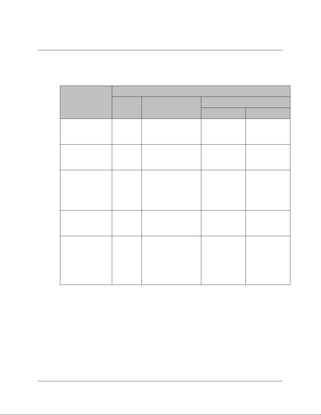
Setting up Audio, Continued
Digital Audio Preference Settings
The following table displays the effects of Dolby Audio Preference setting on audio
outputs, based on the type of audio being decoded:
Input/
Output
MPEG LA
(MPEG1 and
MPEG2)
Dolby Digital PCM Dolby Digital
Dolby Digital Plus
(< 1.5 Mbps)
Dolby Digital Plus
(>= 1.5 Mbps)
MPEG2 AAC,
MPEG4 (AAC and
HEAAC v1 and
v2)
PCM Dolby Digital Compressed
PCM PCM PCM PCM
(follows IEC 61937)
PCM Dolby Digital
(follows IEC 61937)
PCM Dolby Digital
(follows IEC 61937)
PCM MPEG2 AAC,
MPEG4 (AAC and
HEAAC)
(follows IEC 61937)
Digital Audio Preference
S/PDIF HDMI
Dolby Digital
(follows IEC
61937)
Dolby Digital
Plus (No overclocking,
follows SMPTE-
338)
Dolby Digital
(follows IEC
61937)
MPEG2 AAC,
MPEG4 (AAC
and HEAAC)
(follows IEC
61937)
Dolby Digital
(follows IEC
61937)
Dolby Digital
Plus (overclocking x4,
follows IEC
61937)
Dolby Digital
(follows IEC
61937)
MPEG2 AAC,
MPEG4 (AAC
and HEAAC)
(follows IEC
61937)
4035197 Rev C D9865 Satellite Receiver Installation and Operation Guide 4-43
Page 78
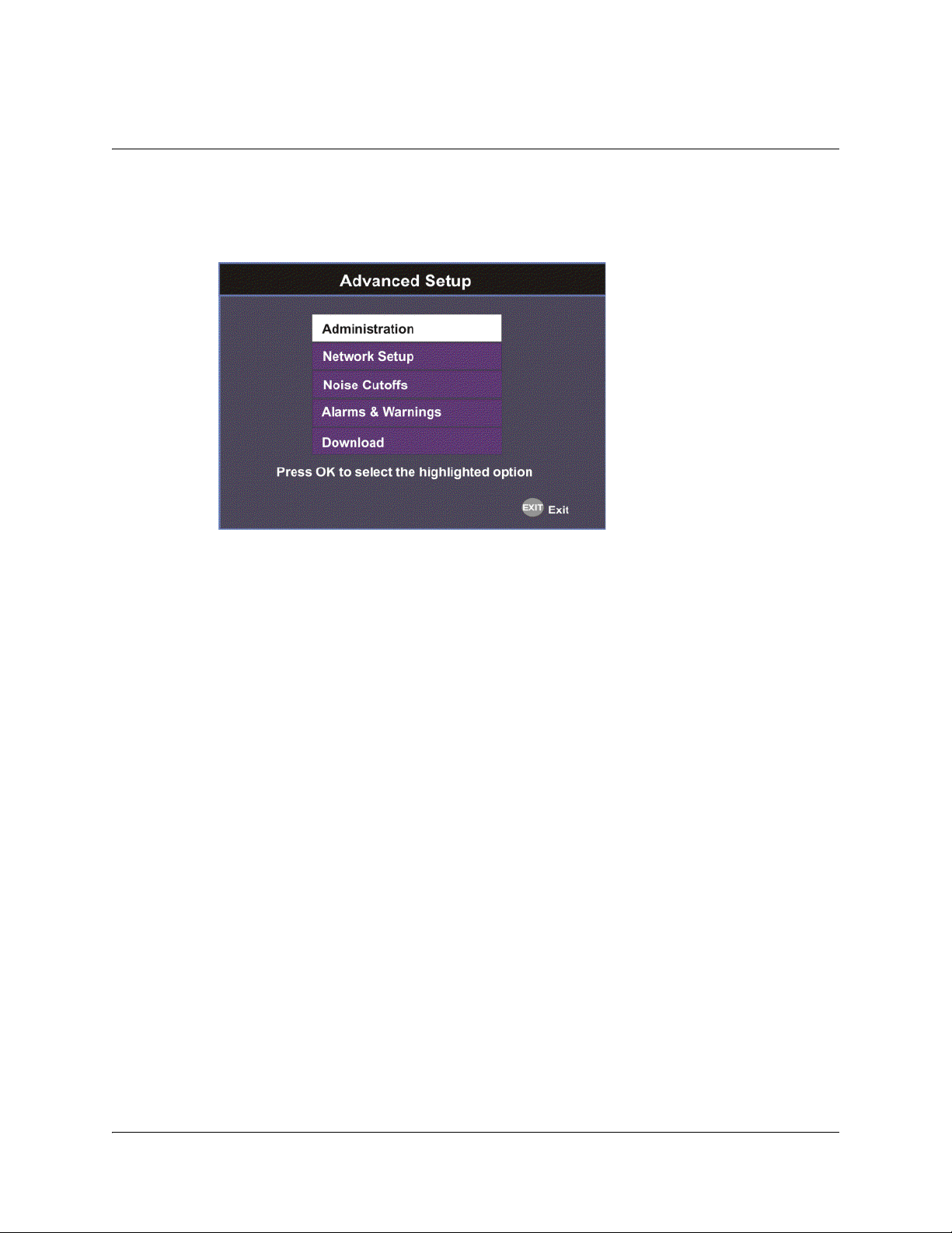
Advanced Setup
To View the Advanced Setup Menu
Proceed as follows to view the Advanced Setup screen.
From the Setup Menu screen, select Advanced Setup and press OK.
The function for the available sub-menus is as follows:
• Administration
From this menu, you can display and control the Lock level, date and time, and
other settings.
• Network Setup (D9865D only)
From this menu, you can configure the receiver for Ethernet operation.
• Noise Cutoffs
From this menu, you can set the noise thresholds.
• Alarms & Warnings
From this menu, you can configure alarm and warning settings.
•Download
From this menu, you can control and view the status of a code download.
4-44 D9865 Satellite Receiver Installation and Operation Guide 4035197 Rev C
Page 79
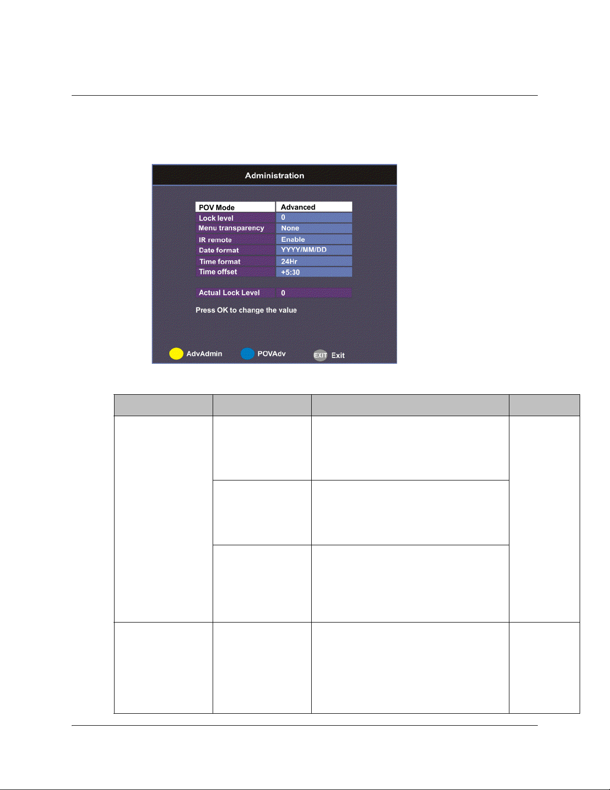
Setting up Advanced User Settings
To Set Up the Advanced User Settings
Proceed as follows to set up the advanced user settings:
1. From the Advanced Setup screen, select Administration and press OK.
2. The following table describes each of the options:
Selection Options Description Default
POV Mode Standard Configures the network controls to the
following pre-defined settings:
CA Mode - Std
Acquisition Mode - Basic
Open Configures the network controls to the
following pre-defined settings:
CA Mode - Open
Acquisition mode - Auto
Advanced Enables the POVAdv menu option,
allowing you to customize the CA
Mode and Acquisition settings. For
more information, see Setting up POV
Mode, on page 4-50.
Lock level 0 to 3 Restricts access and prevents
unauthorized changes to receiver
settings.
For details on changing the lock level,
see Changing the Lock Level, on
page 4-47.
Standard
0
4035197 Rev C D9865 Satellite Receiver Installation and Operation Guide 4-45
Page 80

Selection Options Description Default
Menu
transparency
None, 25%, 50%,
75%, 90%
Set the transparency level of the menus
displayed on-screen.
For example, if set to None, menus are
solid and the video appears behind the
menus. If set to 25%, menus are clear
and the video is visible through the
menus.
IR remote Enable Set to Enable to control the receiver
using the remote control. By default,
the receiver is shipped with the remote
control enabled.
Note: The EPG functions are only
available using the IR remote control.
Disable Set to Disable if you want to disable
the remote control and use the front
panel controls only.
Date Format YYYY/MM/DD,
DD/MM/YYYY,
MM/DD/YYYY
Current date information is displayed
in the Active Alarm and Active
Warning screens.
None
Enable
YYYY/MM/
DD
Time format 24 Hr, 24 Hr
SuspendZero, 12
Hr, 12 Hr
SuspendZero
Time information is displayed in the
Active Alarm and Active Warning
screens.
Time information is normally broadcast
as part of the transmitted digital signal,
and is usually the broadcaster local
time relative to Greenwich Mean Time
(GMT).
Time offset Adjusted in one
hour increments,
from -12:00 to
+13:00, and GMT.
Displays the time zone offset instead of
the true local time. If the current
broadcast time is not your local time,
you must change this time setting.
Actual Lock Level Displays the current lock level.
Adv Admin Displays the Advanced Administration
screen. For more information, see
Changing the Lock Level Password,
on page 4-48.
24 Hr
+05:30
4-46 D9865 Satellite Receiver Installation and Operation Guide 4035197 Rev C
Page 81

Setting up Advanced User Settings, Continued
Changing the Lock Level
Receiver lock levels are password-protected. When an attempt is made to change
the lock level setting, a password prompt is displayed. After the correct password is
entered, you can change the lock level setting.
If the incorrect password is entered (any lock level setting), a message box appears
on-screen to confirm an invalid password entry, and access to the locked options
are denied.
Note: The default password is 1234.
For details on the four lock levels, see D9865 Satellite Receiver Lock Levels, on
page C-2.
Proceed as follows to change the lock level:
1. In the Administration menu, scroll to select Lock Level and press OK. The PIN
Entry screen appears.
2. Press OK to enter the current password using the numeric keypad on the
remote control and press OK. For security reasons, a default character is
substituted for each button pressed.
3. Use
to select a valid lock level (lock levels are displayed from 0 to 3) and
then press OK. The default setting is 0. The Actual Lock Level parameter below
is updated to the new lock level.
Menu options change color (view-only) if disabled by the current lock level
setting.
Important: A virtual channel displayed for 20 seconds or more automatically
becomes the current (Last) channel. As Lock Level 3 disables most Lock Level 0
functions (including channel changes), perform this action before changing the
current Lock Level setting to 3.
4035197 Rev C D9865 Satellite Receiver Installation and Operation Guide 4-47
Page 82

Changing the Lock Level Password
The Advanced Administration sub-menu allows you to change the following:
• Set Lock Level Password - to change the current lock level password (1234).
• Factory Reset - to restore the receiver to factory default settings.
Changing the Lock Level Password
A unique lock level password (4-digit password) protects the current receiver
settings against unauthorized changes. When changing the password, record and
keep this number in a secure location. The default password is 1234.
Important: Proceed with caution when changing the password as this operation
cannot be undone. If the password is lost or is unavailable, contact Cisco customer
support.
To change the lock level password:
1. From the Administration screen, press the yellow button (Adv Admin).
2. Select Set Lock Level Password and press OK.
3. Press OK to enter the current password and press OK. For security, a default
character is substituted for each button pressed.
4. Press OK to enter the new password, any number from 0 to 9, and press OK.
5. Press OK to enter the new password again for password confirmation and press
OK. A message appears informing you that the password was changed
successfully.
Note: If the password is lost or is unavailable, contact Cisco customer support.
4-48 D9865 Satellite Receiver Installation and Operation Guide 4035197 Rev C
Page 83

Changing the Lock Level Password, Continued
Performing a Factory Reset
The Factory Reset (F/R) is used for restoring the receiver’s factory presets (defaults).
When activated, the current receiver settings are replaced by the default settings.
After the factory defaults are restored, you can change the receiver settings as
required.
To restore the factory default settings using the remote control:
1. From the Advanced Administration screen, press the blue button (F/R).
2. Select Yes to reset the receiver and restore to factory defaults. Select No to cancel
the operation.
Following a factory reset, the receiver returns to Standby mode. Wait for the
flashing front panel LED, and then press the Display button on the remote control
or front panel, followed by the Menu button to return to the Main Menu.
Rebooting the Receiver
If you need to reboot the receiver for any reason, you can perform this function
without changing any settings.
To reboot the receiver:
1. From the Advanced Administration screen, press the yellow button (Reboot). A
message appears confirming that you want to reboot the receiver.
2. Select Yes to reboot. Otherwise, select No.
Resetting the Web GUI Login Information
The Reset Login (RstLogin) is used for resetting the username and password used
for Web GUI login to its default values. The default username is admin and the
default password is localadmin.
To reset the login:
1. From the Advanced Administration screen, press the blue button (RstLogin). A
message appears confirming that you want to reset the password to its default
values.
2. Select Yes. Otherwise, select No.
4035197 Rev C D9865 Satellite Receiver Installation and Operation Guide 4-49
Page 84

Setting up POV Mode
To Set Up the POV Mode
Proceed as follows to configure the POV Mode:
Note: Ensure the POV Mode setting is set to Advanced.
1. From the Administration screen, press the blue button (POVAdv).
2. Select the Conditional Access type (CA Mode) that determines which programs
can be viewed via the satellite receiver. Select Std (preferred) or Open. The
default is Std.
Important: In Open mode, the receiver ignores inconsistent scrambling
descriptions within the signal. Operating in this mode may cause the decoder
not to respond to certain advanced uplink controlled features, such as service
replacement.
3. Set the Acquisition Mode used to build channel lists from allowed service lists
(Basic, Auto, or Custom). Select Custom to customize the tables used to obtain
tuning and channel lists.
4. If the Acquisition Mode was set to Custom, you can set the Tuning Source to
indicate whether the receiver is tuned to the received signal using the NIT or a
Preset. The default is NIT.
4-50 D9865 Satellite Receiver Installation and Operation Guide 4035197 Rev C
Page 85

Setting up POV Mode, Continued
5. The Service List Mode indicates which tables are used to obtain tuning and
channel lists. This only applies when Acquisition Mode is set to Custom. Select
Rigorous if all default settings must be present in the received signal. Select
Degraded and only the table parameters present in the received signal will be
used to install the receiver.
The following table displays the default settings for the allowed service lists and
frequency tuning settings.
Allowed Service Lists Auto Basic Custom
BAT No No No
NIT Yes Yes No
SDT Yes No No
PAT Yes No Yes
Tuning Source NIT NIT Preset
4035197 Rev C D9865 Satellite Receiver Installation and Operation Guide 4-51
Page 86

Network Setup
To View the Network Setup Menu
Proceed as follows to view the Network Setup screen (D9865D only).
From the Advanced Setup menu, select Network Setup and press OK.
The function for the available sub-menus is as follows:
•IP Setup
From this menu, you can configure the receiver for Ethernet operation.
•Unicast IP Setup
From this menu, you can configure network destinations for unicast
transmission.
•Multicast IP Setup
From this menu, you can configure network destinations for multicast
transmission.
•SNMP Setup
From this menu, you can configure the password to read and write data to a
device. You can also configure trap destinations.
4-52 D9865 Satellite Receiver Installation and Operation Guide 4035197 Rev C
Page 87

Configuring IP Setup
Setting up the IP Information
The IP Setup screen allows you to set the parameters for communicating with other
equipment via the Ethernet Data and Management ports for MPE applications. The
D9865 supports unicast and multicast IP streaming. There are two Ethernet ports
(Port 1 and Port 2). Click the blue button (Next Port) in the IP Setup menu to toggle
between the two ports.
Note: Only Port 1 is available for this release.
MPE Output
The Multiprotocol Encapsulation (MPE) output provides a means to carry packet
oriented IP protocols on top of a transport stream. The MPE output receives IP
packets from the transport stream and the IP data can be sent through an Ethernet
switch to an IP router or directly to a receiving device.
The diagram below shows an example of the D9865 receiver used in an MPE
application.
4035197 Rev C D9865 Satellite Receiver Installation and Operation Guide 4-53
Page 88

Configuring IP Setup, Continued
Setting the Filter Mode
The filter mode sets the multicast forwarding for MPE data output.
Proceed as follows to set up the filter mode:
1. From the Advanced Setup screen, select IP Setup and press OK.
2. The Filter Mode sets whether all the MPE data is forwarded (Forward All). It
can forward up to 5 PIDs at the maximum bit rates shown in the following table.
Otherwise, select Forward None.
MPE Bit Rate No
Decoding
Multicast 30 Mbps 20 Mbps 15 Mbps
Unicast 20 Mbps 15 Mbps 10 Mbps
3. Set the MPE Optimization setting. Select High Bitrate (default) to accumulate
the IP packets before they are processed in short bursts, increasing the allowable
bit rate of MPE data. Select Low Jitter to emit the IP packets in a constant
stream, resulting in low latency.
5 Mbps SD
Video Decoded
20 Mbps HD
Video Decoded
4-54 D9865 Satellite Receiver Installation and Operation Guide 4035197 Rev C
Page 89

Configuring IP Setup, Continued
Editing an IP Address
Proceed as follows to edit the Network IP Address:
1. From the IP Setup screen, press the yellow button (SetIPAddr).
2. The following table describes each of the options:
Selection Options Description
IP Address 12 digits in length
(###.###.###.###)/
Mask 8 to 32 Sets the Subnet Mask for its
Gateway Address 12 digits in length
(###.###.###.###)
The Network Address, Prefix Mask, and Gateway Address should be changed
together, as a group. The following table shows the most commonly used
Subnet mask values to enter for a chosen IP address mask, which will depend on
the size of your network.
Mask Subnet Mask
8 255.0.0.0
16 255.255.0.0
24 255.255.255.0
Sets the IP Address for its participation
in a Network environment.
participation in a Network
environment.
Sets the Network Gateway Address on
the Network, used to expose the
receiver to a WAN.
Note: Only Port 1 is available for this release.
4035197 Rev C D9865 Satellite Receiver Installation and Operation Guide 4-55
Page 90
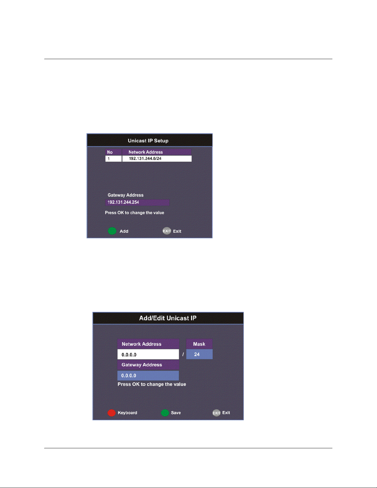
Setting the Unicast IP Address
Viewing the Unicast IP
Unicast transmission is used to send messages to a specific address. You can specify
up to six single network destinations. The Gateway address is necessary if the
network address is not on a local network.
Proceed as follows to view the Unicast IP addresses:
1. From the Network Setup screen, select Unicast IP Setup and click OK.
The Unicast IP Setup screen lists all the IP addresses and its Gateway addresses that
are participating in a Network environment.
Adding a Unicast IP Address
Proceed as follows to add a Unicast IP Address:
1. From the Unicast IP Setup screen, press the green button (Add) to add a new
address.
4-56 D9865 Satellite Receiver Installation and Operation Guide 4035197 Rev C
Page 91

Setting the Unicast IP Address, Continued
2. The following table describes each of the options:
Selection Options Description
Network Address 12 digits in length
(###.###.###.###)
Mask 8 to 32 Sets Subnet Mask for its participation in
Gateway Address 12 digits in length
(###.###.###.###)
The Network Address, Mask, and Gateway Address should be changed together, as
a group. The following table shows the most commonly used Subnet mask values to
enter for a chosen IP address mask, which will depend on the size of your network.
Mask Subnet Mask
8 255.0.0.0
16 255.255.0.0
24 255.255.255.0
3. Select the green button (Save).
Sets the IP Address for its participation
in a Network environment
a Network environment.
Sets the Network Gateway Address on
the Network, used to expose the
receiver to a WAN.
Editing a Unicast IP Address
1. In the Unicast IP Setup screen, scroll to the unicast IP you want to edit using the
buttons.
2. Press OK. The Edit/Delete Unicast IP screen is displayed.
3. Select Edit or press the blue button (Edit). The Add/Edit Unicast IP screen is
displayed.
4. Make the necessary changes.
5. Select the green button (Save).
Deleting a Unicast IP Address
1. In the Unicast IP Setup screen, scroll to the unicast IP you want to delete using
buttons.
the
2. Press OK. The Edit/Delete Unicast IP screen is displayed.
3. Select Delete or press the red button (Delete). A message appears to confirm the
deletion.
4. Press OK.
4035197 Rev C D9865 Satellite Receiver Installation and Operation Guide 4-57
Page 92

Setting the Multicast IP Address
Viewing the Multicast IP Addresses
Proceed as follows to view the Multicast IP addresses:
1. From the Network Setup screen, select Multicast IP Setup and click OK.
The Multicast IP Setup screen lists all the fixed multicast destination IP addresses.
Adding a Multicast IP Address
Proceed as follows to add a Multicast IP Address:
1. From the Multicast IP Setup screen, press the green button (Add) to add a new
address.
2. Set the multicast destination IP address, in the range from 0 to 255 for each of the
four fields in the following format: ###.###.###.###. For example, 225.1.1.1.
3. Press the green button (Save) to save your changes.
4-58 D9865 Satellite Receiver Installation and Operation Guide 4035197 Rev C
Page 93

Setting the Multicast IP Address, Continued
Editing a Multicast IP Address
1. In the Multicast IP Setup screen, scroll to the multicast IP you want to edit using
the
buttons.
2. Press OK. The Edit/Delete Multicast IP screen is displayed.
3. Select Edit or press the blue button (Edit). The Add/Edit Multicast IP screen is
displayed.
4. Make the necessary changes.
5. Select the green button (Save).
Deleting a Multicast IP Address
1. In the Multicast IP Setup screen, scroll to the multicast IP you want to delete
using the
2. Press OK. The Edit/Delete Multicast IP screen is displayed.
3. Select Delete or press the red button (Delete). A message appears to confirm the
deletion.
buttons.
4. Press OK.
4035197 Rev C D9865 Satellite Receiver Installation and Operation Guide 4-59
Page 94
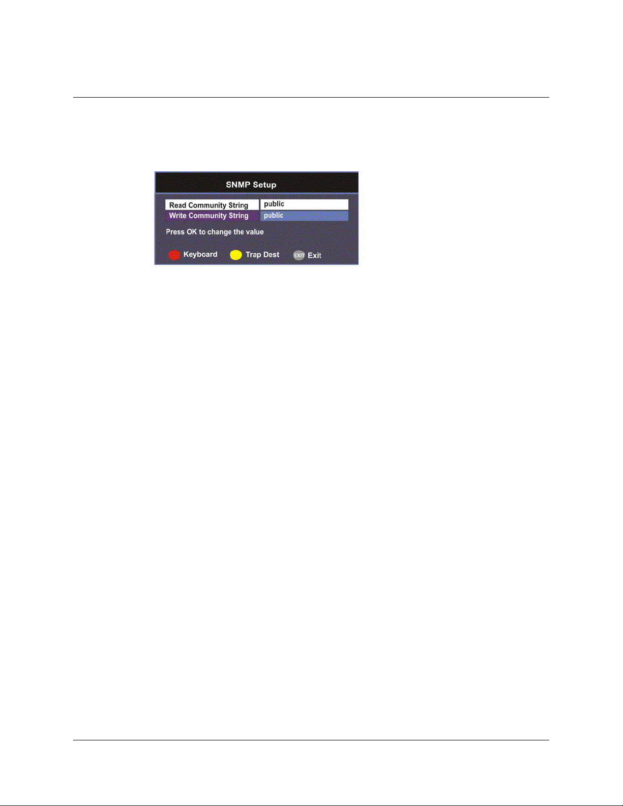
Setting up SNMP
Configuring SNMP Setup
Proceed as follows to configure SNMP:
1. From the Network Setup screen, select SNMP Setup and press OK.
2. Set the Read/Write Community String to public or a custom string. The SNMP
Community Read/Write is used when communicating with a device within an
SNMP environment. These commands allow you to set the password to read
and write data to a device to display diagnostics traps/alarms. The default
community string is public. To set a custom community string, enter an
alphanumeric character string up to 31-characters in length identifying the
password for the device.
Note: The community string is case-sensitive.
4-60 D9865 Satellite Receiver Installation and Operation Guide 4035197 Rev C
Page 95
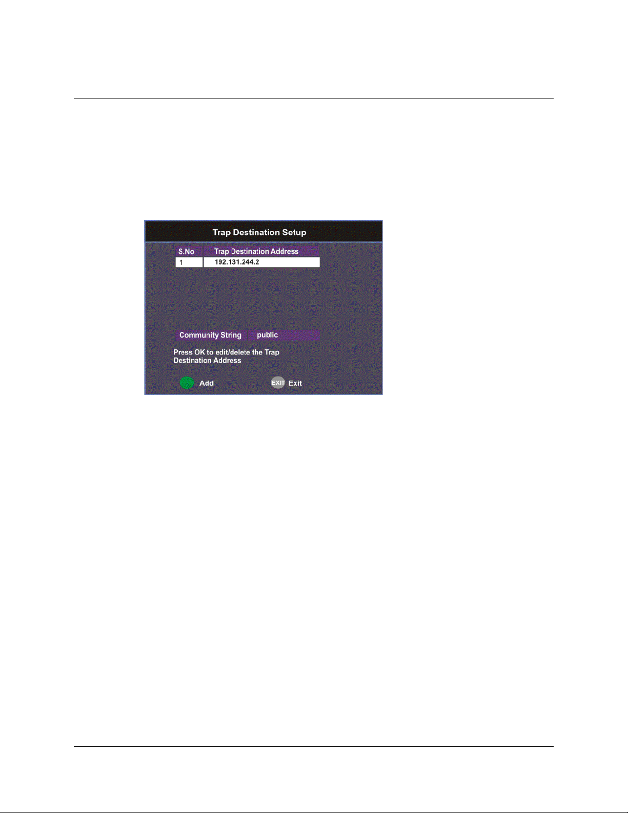
Setting up Trap Destinations
Viewing Trap Destinations
Note: You can assign up to 10 entries to the Trap Destination and Community
String fields.
Proceed as follows to view trap destinations:
From the SNMP Setup screen, press the yellow button (Trap Dest) to view trap
destinations.
The Trap Destination Setup screen displays a list of trap destination addresses and
the associated community string.
4035197 Rev C D9865 Satellite Receiver Installation and Operation Guide 4-61
Page 96

Setting up Trap Destinations, Continued
Adding Trap Destinations
Proceed as follows to add trap destinations:
1. From the Trap Destination Setup screen, press the green button (Add) to add a
trap destination address.
2. The following table describes each of the available options:
Selection Options Description
Trap Destination
Address
Community String public or custom
3. Click the green button (Save) to save the changes.
Up to 12 digits in
length (e.g.,
155.128.100.200).
string. Up to 31
characters
Editing/Deleting Trap Destinations
Proceed as follows to edit/delete trap destinations.
1. In the Trap Destination Setup screen, select the trap destination address you
want to edit or delete and press OK.
2. Press the blue button (Edit) to edit the address. Press the red button (Delete) to
remove the address from the Trap Destination list.
3. If you pressed the blue button, you can edit the Trap Destination Address and
Community String and press the green button (Save) to save your changes.
Enter the destination for SNMP trap
messages for events (i.e., fault
messages).
Set the community string for the trap IP
address above. The default is public.
4. If you pressed the red button (Delete), a warning message appears. Press OK to
delete the selected trap destination entry. Otherwise, press Exit.
4-62 D9865 Satellite Receiver Installation and Operation Guide 4035197 Rev C
Page 97

Configuring Noise Cutoffs
Setting the Noise Cutoff parameters
The Noise Cutoffs screen allows you to set the muting thresholds for both audio
and video in the event of a noisy signal.
Proceed as follows to configure the noise cutoffs:
1. From the Advanced Setup screen, select Noise Cutoffs and press OK. A
message appears confirming that you want to edit the noise cutoffs.
2. Select Yes to edit. Otherwise, select No.
3. The following table describes each of the options:
Selection Options Description Default
Noise Cutoffs Enable or
Disable
Sets whether to enable or disable the noise
cutoffs functionality.
Enable
4035197 Rev C D9865 Satellite Receiver Installation and Operation Guide 4-63
Page 98

Selection Options Description Default
DVB-S/DVB-S2 TS
Mute
DVB-S/DVB-S2 TS
Restore
-5.0 to 20.0 dBThis sets how the receiver reacts when the
signal quality is severely degraded when
using DVB-S or DVB-S2 modulation. This
allows you to set the transport C/N
margin values for the receiver. The
receiver uses these noise values/settings
as limits during normal operation to
determine whether to mute the transport
in the event of a noisy signal, poor signal
or no signal condition.
The mute is the lower limit for the
transport C/N margin setting. The
transport will be muted when the C/N
margin is below the cutoff setting for a
nominal delay of 1 second. The delay is
between the time the condition is first
detected and the time the transport is
muted.
-5.0 to 20.0 dBThis sets how the receiver reacts when the
signal quality is severely degraded when
using DVB-S or DVB-S2 modulation. This
allows you to set the transport C/N
margin values for the receiver. The
receiver uses these noise values/settings
as limits during normal operation to
determine whether to mute the transport
in the event of a noisy signal, poor signal
or no signal condition.
This is the upper limit for the transport C/
N margin setting. The transport will be
un-muted (e.g., restored) when the C/N
margin rises above the Restore setting for
a nominal delay of 8 seconds. The delay is
between the time the condition is first
detected and the time the transport is
restored.
0.0
0.1
4-64 D9865 Satellite Receiver Installation and Operation Guide 4035197 Rev C
Page 99

Selection Options Description Default
Transport Mute
Transport Restore
0.1
0.0
Transport Muted
Transport Restored
Transport
C/N Margin
DVB-S/DVB-S2
Audio Mute
DVB-S/DVB-S2
Audio Restore
-5.0 to 20.0 dBThis is used to set the Audio channel
Cutoff and Restore C/N margin values
(limits) to mute audio when the signal
quality is severely degraded when using
DVB-S or DVB-S2 modulation.
The Cut Off is the lower limit for the audio
C/N margin setting. Audio will be muted
when the C/N margin is below the Cutoff
setting for a nominal delay of 4 seconds.
The delay is between the time the
condition is first detected and the time the
transport is muted.
-5.0 to 20.0 dBThis is used to set the Audio channel
Cutoff and Restore C/N margin values
(limits) to mute audio when the signal
quality is severely degraded when using
DVB-S or DVB-S2 modulation.
The Restore is the upper limit for the
audio C/N margin setting. Audio will be
un-muted (e.g., restored) when the C/N
margin rises above the Restore setting for
a nominal delay of 8 seconds. The delay is
between the time the condition is first
detected and the time the transport is
restored.
0.0
0.1
The following displays the transport and audio default C/N Margin relationships:
Transport Default C/N Margin Relationship
4035197 Rev C D9865 Satellite Receiver Installation and Operation Guide 4-65
Page 100

Configuring Noise Cutoffs, Continued
Audio Mute
Audio Restore
0.1
0.0
Audio Muted
Audio Restored
Audio
C/N Margin
Audio Default C/N Margin Relationship
4. If you want to restore the transport stream and audio C/N margin options to
their factory set (default) values, press the blue button (Default). A message
appears confirming to restore to default values. Press OK to confirm.
5. Press the green button (Save) to save and apply the settings to the receiver.
4-66 D9865 Satellite Receiver Installation and Operation Guide 4035197 Rev C
 Loading...