

Page 1

Catalyst 2984G, 2948G-GE-TX,
and 2980G Switch Hardware
Installation Guide
October 20 03
Corporate Headquarters
Cisco Systems , Inc.
170 West Tasman Drive
San Jose, CA 95134-1706
USA
http://www.cisco.com
Tel: 408 526-4000
800 553-NETS (6387)
Fax: 408 526-4100
Customer Order Number: DOC-786286=
Text Part Number: 78-6286-05
Page 2

THE SPECIFICATIONS AND INFORMATION REGARDING THE PRODUCTS IN THIS MANUAL ARE SUBJECT TO CHANGE WITHOUT
NOTICE. ALL STATEMENTS, INFORMATION, AND RECOMMENDATIONS IN THIS MANUAL ARE BELIEVED TO BE ACCURATE BUT
ARE PRESENTED WITHOUT WARRANTY OF ANY KIND, EXPRESS OR IMPLIED. USERS MUST TAKE FULL RESPONSIBILITY FOR
THEIR APPLICATION OF ANY PRODUCTS.
THE SOFTW ARE LICENSE AND LIMITED WARRANTY FO R THE A CCOMPANYING PR ODUCT ARE S ET FORTH IN THE INFORMATION
PACKET THAT SHIPPED WITH THE PRODUCT AND ARE INCORPORATED HEREIN BY THIS REFERENCE. IF YOU ARE UNABLE TO
LOCATE THE SOFTWARE LICENSE OR LIMITED WARRANTY, CONTACT YOUR CISCO REPRESENTATIVE FOR A COPY.
The following information is for FCC compliance of Class A devices: This equipment has been tested and found to comply with the limits for a Class
A digital device, pursuant to part 15 of the FCC rules. These limits are designed to provide reasonable protection against harmful interference when
the equipment is operated in a commercial environment. This equipment generates, uses, and can radiate radio-frequency energy and, if not installed
and used in accordance with the instruction manual, may cause harmful interference to radio communications. Operation of this equipment in a
residential area is likely to cause harmful interference, in which case users will be required to cor rect t he interference at their own expense.
The following information is for FCC complia nce of Class B devices: The equi pment des cribed in this manual generates and may rad iate
radio-frequency energy. If it is not installed in accordance with Cisco’s installation instructions, it may cause interference with radio and television
reception. This equipment has been tested and found to comply with the limits for a Class B digital device in accordance with the specifications in
part 15 of the FCC rules. These specifications are designed to provide reasonable protection against such interference in a residential installation.
However, there is no guarantee that interference will not occur in a particular installation.
Modifying the equipment wit hou t Cisco’s written autho riz atio n may resul t in the equi pme nt no longe r comply ing with FCC re quir ements for Class
A or Class B digital devices. In that event, your right to use the equipm ent may be lim ited by FCC regulations, and you may be required to correct
any interference to radio or television communicati ons at your own expense.
You can determine whether your equipment is causing int erferen ce by turning it off. If the inter ference stops, it was probably caused by the Cisco
equipment or one of its peripheral devices. If the equipment causes interference to radio or television reception, try to correct the interference by
using one or more of the following measures:
• Turn the television or radio antenna until the interferenc e stops.
• Move the equipment to one side or the other of the television or radio .
• Move the equipment farther away from the television or radio.
• Plug the equipment into an outlet that is on a different circ uit from the tel evision or radio. (That is, make certain the equip ment and the television
or radio are on circuits controlled by different circui t breakers or fuses.)
Modifications to this product not auth orized by Cisco Sys tems, Inc. could void the FCC approval and negate your auth ority to op erate the prod uct.
The Cisco implementation of TCP header compression is an adap tati on o f a pr ogr am d eveloped by the University of California, Berkeley (UCB) as
part of UCB’s public domain version of the UNIX operating system. All rights reserved. Copyright © 1981, Regents of the University of California.
NOTWITHSTANDING ANY OTHER WARRANTY HEREIN, ALL DOCUMENT FILES AND SOFTWARE OF THESE SUPPLIERS ARE
PROVIDED “AS IS” WITH ALL FAULTS. CISCO AND THE ABOVE-NAMED SUPPLIERS DISCLAIM ALL WARRANTIES, EXPRESSED
OR IMPLIED, INCLUDING, WITHOUT LIMITATION, THOSE OF MERCHANTABILITY, FITNESS FOR A PARTICULAR PURPOSE AND
NONINFRINGEMENT OR ARISING FROM A COURSE OF DEALING, USAGE, OR TRADE PRACTICE.
IN NO EVENT SHALL CISCO OR ITS SUPPLIERS BE LIABLE FOR ANY INDIRECT, SPECIAL, CONSEQUENTIAL, OR INCIDENTAL
DAMAGES, INCLUDING, WITHOUT LIMITATION, LOST PROFITS OR LOSS OR DAMAGE TO DATA ARISING OUT OF THE USE OR
INABILITY TO USE THIS MANUAL, EVEN IF CISCO OR ITS SUPPLIERS HAVE BEEN ADVISED OF THE POSSIBILITY OF SUCH
DAMAGES.
Page 3

CCIP, CCSP, the Cisco Arrow logo, the Cisco Powered Network mark, Cisco Unity, Follow Me Browsing, FormShare, and StackWise are trademarks
of Cisco Systems, Inc.; Changing the Way We Work, Live, Play, and Learn, and iQuick Study are service marks of Cisco Systems, Inc.; and Aironet,
ASIST, BPX, Catalyst, CCDA, CCD P, CCIE, CCNA, C CNP, Cis co, the Ci sco Certi fied In ternetwo rk Exp ert logo, C isco IOS, the Cisco IOS logo ,
Cisco Press, Cisco Systems, Cisco Systems Capital, the Cisco Systems logo, Empowering the Internet Generation, Enterprise/Solver, EtherChannel,
EtherSwitch, Fast Step, GigaStack, Internet Quotient, IOS, IP/TV, iQ Expertise, the iQ logo, iQ Net Readiness Scorecard, LightStream, MGX,
MICA, the Networkers logo, Networking Academy, Network Registrar, Packet, PIX, Post-Routing, Pre-Routing, RateM UX, Registrar, Scri ptShare,
SlideCast, SMARTnet, StrataView Plus, Stratm, SwitchProbe, TeleRouter, The Fastest Way to Increase Your Internet Quotient, TransPath, and VCO
are registered trademarks of Cisco Systems, Inc. and/or its affiliates in the U.S. and certain other countries.
All other trademarks mentioned in this document or Web site are the property of their respective owners. The use of the word partner does not imply
a partnership relationship between Cis co and any oth er company . (0304 R)
Catalyst 2984G, 2948G-GE-T X, and 2980 G Swit ch Hardware Installation Guide
Copyright © 1999–2003, Cis co System s, Inc. Al l rights re served.
Page 4

Page 5

CONTENTS
Cisco Limite d Li fe ti m e Ha rd w a r e Wa rr a nt y Ter m s xi
Preface xv
Audience xv
Organization xv
Related Documentation xvi
Conventions xvii
Obtaining Documentation xxiii
Cisco.com xxiii
Documentation CD-ROM xxiii
Ordering Documentation xxiv
Documentation Feedback xxiv
Obtaining Technical Assistance xxiv
Cisco TAC Website xxv
Opening a TAC Ca se xxv
TAC Case Priority Definitions xxv
CHAPTER
78-6286-05
Obtaining Additional Publicati ons and Information xxvi
1 Product Overview 1-1
Switch Description 1-1
GBIC Module Support 1-3
SFP Module Support 1-3
Switch Features 1-4
Catalyst 2984G, 2948G-GE-TX, and 2980G Switch Hardware Installation Guide
v
Page 6

Contents
Port Locati on s 1-6
10/100 and 10/100/1000 Ports 1-6
Catalyst 294 8G and 2980G Switc h Ports 1-7
Catalyst 2948G-GE-TX Switch Ports 1-7
Switch Components 1-7
Management Ports 1-8
Console Serial Port 1-8
10BASE-T and 10/100BASE-T Ports 1-8
Front Panel LEDs 1-8
Airflow 1-9
Power Supplies 1-11
CHAPTER
CHAPTER
2 Site Planning 2-1
Site Power Requirements and Heat Dissipation 2-2
System Ground Connect ion Guidelines (Catalyst2948G and 2980G Switches
Only)
2-3
Connecting the Swi tch to Earth Ground 2-5
Site-Planning Checklist 2-7
3 Installing the Switc h 3-1
Preparing for Installation 3-2
EMC Regulatory Statements 3-2
U.S.A. 3-2
Taiwan 3-2
VCCI Class A Notice for Japan 3-3
Korea 3-3
Class A Notice for Hungary 3-4
Checking the Shipping Container 3-4
Catalyst 2948G and 2980G Sw i tches 3-4
Catalyst 2948G-GE-TX Switches 3-5
vi
Catalyst 2984G, 2948G-GE-TX, and 2980G Switch Hardware Installation Guide
78-6286-05
Page 7

Installing the Cat alyst 2948G and 2980G Switc hes 3-6
Required Installation Tools 3-6
Rack-Mounting the Catalyst2948G and 2980G Switches 3-7
Installing the Catalyst 2948G-GE-TX Switch 3-9
Rack-Mounting the Catalyst 2948G-GE-TX Switch 3-10
Removing Screws from the Switch 3-10
Attaching Bracke ts to the Switch 3-11
Mounting the Switch in a Rack 3-14
Attaching the Cable Guide 3-15
Wall-Mounting the Catalyst 2948G-GE-TX Switch 3-16
Attaching the Brackets to the Switch for Wall-Mounting 3-16
Attaching the RPS Connector Cover 3-17
Mounting the Switch on a Wall 3-17
Mounting the Catalyst 2948G-GE-TX Switch on a Ta ble or Shelf 3-19
Connecting Power to the Switches 3-19
Contents
CHAPTER
78-6286-05
Connecting to 10/100 and 10/100/1000 Ports 3-20
Connecting a Termi nal to the Console Seria l and Ethernet Management
Ports
3-22
Verifying Switch Operation 3-23
4 Configuring the Gigabit Ethernet Ports 4-1
Installing, Removing, and Maintaining GBICs 4-2
GBIC Features 4-2
Port Cabling Specifications 4-4
GBIC Optical Power Characteristics 4-5
GBIC Cabling Restrictions 4-5
Installing GBICs 4-6
Removing GBICs 4-9
GBIC Maintenance Guidelines 4-10
Catalyst 2984G, 2948G-GE-TX, and 2980G Switch Hardware Installation Guide
vii
Page 8

Contents
Patch Cord 4-10
Patch Cord Configuration Example 4-11
Patch Cord Installation 4-11
Connecting To an SFP Module 4-12
CHAPTER
APPENDIX
APPENDIX
APPENDIX
5 Troubleshooting the Installation 5-1
Getting Started 5-2
Problem Solving to the System Component Level 5-2
Identifying Startup Problems 5-3
Troubleshooting the Power Supply 5-4
Contacting Custo m er Service 5-5
A Specifications A-1
Console Serial Port A-1
10BASE-T and 10/100BASE-T Ethernet Manageme nt Ports A-2
Catalyst2948G Switch Specifications A-2
Catalyst2948G-GE-TX Switch Specifications A-5
Catalyst2980G Switch Specifications A-6
B Repacking a Switch B-1
C Differential Mode Delay C-1
APPENDIX
viii
D Translated Safety Warnings D-1
Warning Definition D-2
Safety Information Referral Warning D-7
Qualified Personnel Warning D-9
Invisible Laser Radiation Warning D-10
Catalyst 2984G, 2948G-GE-TX, and 2980G Switch Hardware Installation Guide
78-6286-05
Page 9

I
NDEX
Contents
Laser Radiation D-11
Attaching the Cisco RPS (model PWR300-AC-RPS-N1) D-13
Attaching the Cisco RPS (model PWR600-AC-RPS) D-14
Attaching the Cisco RPS (model PWR675-AC-RPS-N1) D-15
Redundant Power Supply Connection Warning D-17
Switch Installation Warning D-18
Chassis Warning for Rack-Mounting an d Servicing D-20
78-6286-05
Catalyst 2984G, 2948G-GE-TX, and 2980G Switch Hardware Installation Guide
ix
Page 10

Contents
Catalyst 2984G, 2948G-GE-TX, and 2980G Switch Hardware Installation Guide
x
78-6286-05
Page 11

Cisco Limited Lifetime Hardware
Warranty Terms
There are special terms applicable to your hardwa re warranty and v arious services
that you can use during the warranty period. Your formal Warranty Statement,
including the warranty applicable to Cisco software, is included on the Cisco
Documentation CD and on Cisco.com. Follow these steps to access and download
the Cisco Information Packet and your warranty docu me nt f rom the CD or
Cisco.com.
1. Launch your br owser, and go to t his U RL :
http://www.cisco.com/univercd/cc/td/doc/es_inpck/cetrans.htm
78-6286-05
The Warranties and License Agre emen ts pag e appe ars.
2. To read the Cisco In format ion Packet, follow these steps:
a. Click the Information Packe t Number field, and make sure that the part
number 78-5235-02F0 is hig hlighted.
b. Select the language in whic h you would like to rea d the docum ent.
c. Click Go.
The Cisco Limited Warranty and Software License page from the
Information Packet appears.
d. Read the docum en t onli ne, o r c lick th e PDF icon to download an d pr int
the document in Adobe Portable Document Format (PDF).
Catalyst 2984G, 2948G-GE-TX, and 2980G Switch Hardware Installation Guide
xi
Page 12

Cisco Limited Lifetime Hardware Warranty Terms
Note You must have Adobe Acrobat Reader to view and print PDF
files. You can download the reader fr om Adobe’s website:
http://www.adobe.com
3. To read translated and loc alized warra nty info rmatio n about yo ur product ,
follow these st eps:
a. Enter this part number in the Warranty Document Number field:
78-6310-02C0
b. Select the language in which you would like to view the document.
c. Click Go.
The Cisco warr an t y p ag e ap pear s .
d. Read the docum en t onli ne, o r c lick th e PDF icon to download an d pr int
the document in Adobe Portable Document Format (PDF).
You can also c ontact th e Cisco servi ce and suppo rt website fo r assistanc e:
http://www.cisco.com/public/Support_root.shtml.
xii
Duration of Hardware Warranty
A Cisco product h ard ware wa rrant y i s s uppo rte d f or a s l on g as th e or ig ina l e nd
user continues to own or use the product, provided that the fan and power supply
warranty is limited to five (5) years. In the event of a discontinuance of product
manufacture, the Cisco warranty support is limited to five (5) years from the
announcement of the d isco nt inua nce.
Replacement, Repair, or Refund Policy for Hardware
Cisco or its service center will use commercially reasonable efforts to ship a
replacement part with in ten (10) wor king days af ter receip t of the Retur n
Materials Authorization (RMA) request. Actual delivery times can vary,
depending on th e cu sto mer lo cati on.
Cisco reserves the right to refund the pu rchase pr ice as its exclusive warranty
remedy.
To Receive a Return Materials Authorization (RMA) Number
Contact the company from whom you purchased the product. If you purchased the
product directly from Cisco, contact your Cisco Sales and Service Representative.
Catalyst 2984G, 2948G-GE-TX, and 2980G Switch Hardware Installation Guide
78-6286-05
Page 13

Cisco Limited Lifetime Hardware Warranty Terms
Complete the information below, and keep it for reference.
Company product pu rcha sed from
Company telephone num be r
Product model number
Product serial numbe r
Maintenance contract number
78-6286-05
Catalyst 2984G, 2948G-GE-TX, and 2980G Switch Hardware Installation Guide
xiii
Page 14

Cisco Limited Lifetime Hardware Warranty Terms
xiv
Catalyst 2984G, 2948G-GE-TX, and 2980G Switch Hardware Installation Guide
78-6286-05
Page 15
Audience
Preface
This preface describes the audience, organization, and conventions of the
Catalyst 2984G, 2948G-GE-TX, and 2980G Switch Hardware Installation Guide
and provides inform at ion on h ow to obta in r ela ted do cu ment atio n.
To use this hard ware gui de , you sh ould be fam il iar wi th e lec tron ic cir cu itr y and
wiring practices an d p re fe rably b e a n electronic or elect ro me ch an ica l te ch nician.
Organization
This guide is organized as follows:
Chapter Title Description
Chapter 1 Product Overview Lists and describe s th e hardware feat ur es
Chapter 2 Site Planning Describes how to prepar e you r site fo r t he
Chapter 3 Installing the
78-6286-05
and functionality of the Catalyst 2948G,
2948G-GE-TX, and 2980G sw it ches .
installation of the switch.
Describes how to install the Catalyst 2948G,
Switch
Catalyst 2984G, 2948G-GE-TX, and 2980G Switch Hardware Installation Guide
2948G-GE-TX, and 2980G sw it ches .
Provides procedures for removing and
installing chassis components.
xv
Page 16

Related Documentation
Preface
Chapter Title Description
Chapter 4 Gigabit Ethernet
Port Configuration
Chapter 5 Troubleshooting
the Installation
Appendix A Specifications Lists C atalyst 2948G an d 2 980 G sw itch
Appendix B R epac king
a Switch
Appendix C Differential Mod e
Delay
Appendix D Translated Safety
Warnings
Describes the feat u res a nd configur ation of
the Gigabit Etherne t p ort s.
Provides troubleshooting guidelines for the
initial hardware installation and suggests
steps to help isolate and resol ve problems.
specifications.
Provides procedures to re pack your
Catalyst 2948G or 2980G switch in the event
that you have to re tur n it to the facto ry.
Describes the natu re a nd cau ses of
differential mode delay (DMD ) and ways to
prevent it.
Repeats in multiple languages the warnings
in this guide.
Related Documentation
Refer to the follo wing docum ents for additional Cata lyst 4500 series information:
• Software Configuration Guide—Catalyst 45 00 Seri es, C at alyst 2948G , an d
Catalyst 2980G Switches
• Command Reference—Catalyst 4 500 S erie s, Cataly st 2948G, and Cat alyst
2980G Switches
• System Message Guide—Catalyst 4500 Series, Catalyst 2948G, and Catalyst
2980G Switches
Catalyst 2984G, 2948G-GE-TX, and 2980G Switch Hardware Installation Guide
xvi
78-6286-05
Page 17

Preface
Conventions
This docume nt u s es the f ol lowing conventions:
Conventions
Convention Description
boldface font Commands and keywords a re in boldface.
italic font Arguments for which you supply values are in ita li cs.
[ ] Elements in square brackets are optional.
{ x | y | z } Alternative keywords are grouped in braces an d
separated by vertical ba rs.
[ x | y | z ] Optional alterna tive keywords are grouped in brac kets
and separated by vertical bars.
string A nonquoted set of characters. Do no t use quotatio n
marks around the string or the string will includ e the
quotation marks.
screen font Terminal sessions and information the system displays
are in
screen font.
boldface screen
font
italic screen font Arguments for which you supply values are in italic
^ The symbol ^ r epre se nts t he key labe led Con trol— fo r
< > Nonprinting char acters, suc h as passwords are in angle
Information you must enter is in boldface screen font.
screen
font.
example, the key combination ^D in a screen display
means hold down the Control key while you press the D
key.
brackets.
78-6286-05
Notes use the following conventions:
Note Means reader take note. Notes contain helpful suggestions or references to
material not covered in the pub lication .
Catalyst 2984G, 2948G-GE-TX, and 2980G Switch Hardware Installation Guide
xvii
Page 18

Conventions
Preface
Cautions use the following conventions:
Caution Means re ader be careful. In this situat ion, you migh t do someth ing that co uld
result in equipment damage or l oss of data.
Warnings use the following conventions:
Warning
Waarschuwing
IMPORTANT SAFETY INSTRUCTIONS
This warning symbol means danger. You are in a situation that could cause
bodily injury. Before you work on any equipment, be aware of the hazards
involved with electrical circuitry and be familiar with standard practices f or
preventing accidents. Use the statement number provided at the end of each
warning to locate its translation in the translated safety warnings that
accompanied this device.
Statement 1071
SAVE THESE INSTRU CTIO NS
BELANGRIJKE VEILIGHEIDSINSTRUCTIES
Dit waarschuwingssymbool betekent gevaar. U verkeert in een situatie die
lichamelijk letsel kan veroorzaken. Voordat u aan enige apparatuur gaat
werken, dient u zich bewust te zijn van de bij elektrische schakelingen
betrokken risico's en dient u op de hoogte te zijn van de standaard praktijken
om ongelukken te voorkomen. Gebruik het nummer van de verklaring
onderaan de waarschuwing als u een vertaling van de waarschuwing die bij
het apparaat wordt geleverd, wilt raadplegen.
BEWAAR DEZE INSTRUCTIES
xviii
Catalyst 2984G, 2948G-GE-TX, and 2980G Switch Hardware Installation Guide
78-6286-05
Page 19

Preface
Conventions
Varoitus
Attention
Warnung
TÄRKEITÄ TURVALLISUUSOHJEITA
Tämä varoitusmerkki merkitsee vaaraa. Tilanne voi aiheuttaa ruumiillisia
vammoja. Ennen kuin käsittelet laitteistoa, huomioi sähköpiirien
käsittelemiseen liittyvät riskit ja tutustu onnettomuuksien yleisiin
ehkäisytapoihin. Turvallisuusvaroitusten käännökset löytyvät laitteen
mukana toimitettujen käännettyjen turvallisuusvaroitusten joukosta
varoitusten lopussa näkyvien lausuntonumeroiden avulla.
SÄILYTÄ NÄMÄ OHJEET
IMPORTANTES INFORMATIONS DE SÉCURITÉ
Ce symbole d'avertissement indique un danger. Vous vous trouvez dans une
situation pouvant entraîner des blessures ou des dommages corporels. Avant
de travailler sur un équipement, soyez conscient des dangers liés aux circuits
électriques et familiarisez-vous avec les procédures couramment utilisées
pour éviter les accidents. Pour prendre connaissance des traductions des
avertissements figurant dans les consignes de sécurité traduites qui
accompagnent cet appareil, référez-vous au numéro de l'instruction situé à la
fin de chaque avertissement.
CONSERVEZ CES INFORMATIONS
WICHTIGE SICHE RHEIT SHINWEI SE
78-6286-05
Dieses Warnsymbol bedeutet Gefahr . Sie befinden sich in einer Situation, die
zu Verletzungen führen kann. Machen Sie sich vor der Arbeit mit Geräten mit
den Gefahren elektrischer Schaltungen und den üblichen Verfahren zur
Vorbeugung vor Unfällen vertraut. Suchen Sie mit der am Ende jeder W arnung
angegebenen Anweisungsnummer nach der jeweiligen Übersetzung in den
übersetzten Sicherheitshinweisen, die zusammen mit diesem Gerät
ausgeliefert wurden.
BEWAHREN SIE DIESE HINWEISE GUT AUF.
Catalyst 2984G, 2948G-GE-TX, and 2980G Switch Hardware Installation Guide
xix
Page 20

Conventions
Preface
Avvertenza
Advarsel
Aviso
IMPORTANTI ISTRUZIONI SULLA SICUREZZA
Questo simbolo di avvertenza indica un pericolo. La situazione potrebbe
causare infortuni alle persone. Prima di intervenire su qualsiasi
apparecchiatura, occorre essere al corrente dei pericoli relativi ai circuiti
elettrici e conoscere le procedure standard per la prevenzione di incidenti.
Utilizzare il numero di istruzione presente alla fine di ciascuna avvertenza
per individuare le traduzioni delle avvertenze riportate in questo documento.
CONSERVARE QUESTE ISTRUZIONI
VIKTIGE SIKKERHETSINSTRUKSJONER
Dette advarselssymbolet betyr fare. Du er i en situasjon som kan føre til skade
på person. Før du begynner å arbeide med noe av utstyret, må du være
oppmerksom på farene forbundet med elektriske kretser, og kjenne til
standardprosedyrer for å forhindre ulykker. Bruk nummeret i slutten av hver
advarsel for å finne oversettelsen i de oversatte sikkerhetsadvarslene som
fulgte med denne enheten.
TA VARE PÅ DISSE INSTRUKSJONENE
INSTRUÇÕES IMPORTANTES DE SEGURANÇA
Este símbolo de aviso significa perigo. Você está em uma situação que poderá
ser causadora de lesões corporais. Antes de iniciar a util ização de qualquer
equipamento, tenha conhecimento dos perigos envolvidos no manuseio de
circuitos elétricos e familiarize-se com as práticas habituais de prevenção de
acidentes. Utilize o número da instrução fornecido ao final de cada aviso para
localizar sua tradução nos avisos de segurança traduzidos que acompanham
este dispositivo.
xx
GUARDE ESTAS INSTRUÇÕES
Catalyst 2984G, 2948G-GE-TX, and 2980G Switch Hardware Installation Guide
78-6286-05
Page 21
Preface
Conventions
¡Advertencia!
Varning!
INSTRUCCIONES I MPORTANTES DE SEGURIDAD
Este símbolo de aviso indica peligro. Existe riesgo para su integridad física.
Antes de manipular cualquier equipo, considere los riesgos de la corriente
eléctrica y familiarícese con los procedimientos estándar de prevención de
accidentes. Al final de cada advertencia encontrará el número que le ayudará
a encontrar el texto traducido en el apartado de traducciones que acompaña
a este dispositivo.
GUARDE ESTAS INSTRUCCIONES
VIKTIGA SÄKERHETSANVISNINGAR
Denna varningssignal signalerar fara. Du befinner dig i en situation som kan
leda till personskada. Innan du utför arbete på någon utrustning måste du vara
medveten om farorna med elkretsar och känna till vanliga förfaranden för att
förebygga olyckor. Använd det nummer som finns i slutet av varje varning för
att hitta dess översättning i de översatta säkerhetsvarningar som medföljer
denna anordning.
SPARA DESSA ANVISNINGAR
78-6286-05
Catalyst 2984G, 2948G-GE-TX, and 2980G Switch Hardware Installation Guide
xxi
Page 22

Conventions
Preface
xxii
Catalyst 2984G, 2948G-GE-TX, and 2980G Switch Hardware Installation Guide
78-6286-05
Page 23

Preface
Obtaining Documentation
Cisco provides several ways to obta in d ocume nta tio n, t echn ica l assi stan ce , a nd
other technical resources. These sections explain how to obtain technical
information from Cisco Syst ems.
Cisco.com
You can access the most current Cisco documentation on the World Wide Web at
this URL:
http://www.cisco.com/univercd/home/home.htm
You can access the Cisco website at this URL:
http://www.cisco.com
International Cisco websites can be accessed from this URL:
http://www.cisco.com/public/countries_languages.shtml
Obtaining Documentation
Documentation CD-ROM
Cisco documentation and additional literature are available in a Cisco
Documentation CD-ROM package, which ma y have shipped with your prod uct.
The Documentation CD-ROM is updated regularly and may be more current than
printed documentat ion. The CD-ROM package is available as a single uni t or
through an annua l or q uart erl y subsc ript ion .
Registered Cisco.c om user s can order a sing le Docume ntation CD-ROM (product
number DOC-CONDOCCD=) through the Cisco Ordering tool:
http://www.cisco.com/en/US/partner/ordering/ordering_place_ order_orde ring_t
ool_launch.html
All users can or der a nn ual or qu ar ter ly su bsc ripti ons thr ough the onl ine
Subscription Store:
http://www.cisco.com/go/subscription
Catalyst 2984G, 2948G-GE-TX, and 2980G Switch Hardware Installation Guide
78-6286-05
xxiii
Page 24

Obtaining Technical Assistance
Ordering Documentation
You ca n find ins truc tio ns for or de ring do cu ment atio n a t t his U RL:
http://www.cisco.com/univercd/cc/td/doc/es_inpck/pdi.htm
You can ord er Cisco docum entat ion in these way s:
• Registered Cisco.com u sers (Cisco d irect custo mers) can ord er Cisco pr oduct
documentation fr om t he N et working Prod uc ts M arketPlac e:
http://www.cisco.com/en/US/partner/ordering/index.shtml
• Nonregistered Cisco.com users c an order docum entat ion through a local
account representat ive by calling Cisco Systems Corporat e Headqua rters
(California, USA. ) at 408 526-7 208 or, elsewhere in North Amer ica, by
calling 800 553-NETS (6387) .
Documentation Feedback
You can submit comments electronically on Cisco.com. On the Cisco
Documentation hom e page, cli ck Feedback at the top of the page.
You ca n sen d y our c om ment s in e -m ail t o bug-doc @c isc o.c om.
Preface
You can submit comments by using the response card (if present) behind the front
cover of your document or by writing to the following address:
Cisco Systems
Attn: Customer Docume nt Ordering
170 West Tasman Dr ive
San Jose, CA 95134- 988 3
We appreciate yo ur comm ents .
Obtaining Technical Assistanc e
For all customers, partners, resellers, and distributors who hold valid Cisco
service contracts, the Cisco Technical Assistance Center (TA C) provides 24-hour,
award-winning technical sup port services, online and over the phone. Cisco.com
features the Cisc o TAC website as an o nline star ting point fo r technical as sistance.
Catalyst 2984G, 2948G-GE-TX, and 2980G Switch Hardware Installation Guide
xxiv
78-6286-05
Page 25

Preface
Cisco TAC Website
The Cisco TAC website ( http://www.cisco.com/tac) provides online documents
and tools for trou blesh oot ing and re solving t ech nica l issu es with Ci sco p rod ucts
and technologies. The Cisco TAC website is available 24 hours a day, 365 days a
year.
Accessing all the to ols o n th e Cisc o TAC website requires a Cisco.com use r ID
and password. If you have a valid service contract but do not have a login ID or
password, register at t his UR L:
http://tools.cisco.com/RPF/register/register.do
Opening a TAC Case
The online TAC Case Open Tool (http://www.cisco.com/tac/caseopen) is the
fastest way to open P3 and P4 cases. (Your network is minimally impaired or you
require product in for mat ion). Af ter you d esc rib e you r situ ation , th e TAC Case
Open Tool automatically recommends resources for an immediate solution. If
your issue is not r esol ved usin g th ese rec om mend ati ons , your c as e w ill be
assigned to a Cisc o TAC engineer.
For P1 or P2 cases (your product ion n etwork i s down or severely degraded) or if
you do not have Internet ac cess, con tac t Ci sco TAC by telephone. Cisco TAC
engineers are assigned immediately to P1 and P2 cases to help keep your business
operations running smoothly.
Obtaining Technical Assistance
To open a case by t eleph one , use o ne of t he fol lowing nu mbe rs:
Asia-Pacific: +61 2 8446 7411 (Australia : 1 800 805 227)
EMEA: +32 2 704 55 55
USA: 1 800 553-2447
For a complete listing of Cisco TAC contacts, go to this URL:
http://www.cisco.com/warp/public/687/Directory/DirTAC.shtml
TAC Case Priority Definitions
To ensure that all cases are reported in a standard format, Cisco has established
case priority definitions.
Catalyst 2984G, 2948G-GE-TX, and 2980G Switch Hardware Installation Guide
78-6286-05
xxv
Page 26

Preface
Obtaining Additional Publications and Information
Priority 1 (P1)—Your network is “down” or there is a critical impact to your
business operations. You and Cisco will commit al l necessar y resour ces aroun d
the clock to resolve the situation.
Priority 2 (P2)—Opera tion of an existing netwo rk is severely degraded, or
significant aspects of y our business ope rat ion are negatively affected by
inadequate performa nce of Cisco pro duc ts. You and Cisco will commit full-time
resources during normal business hours to reso lve the situation .
Priority 3 (P3)—O perational performa nce of your network is impaired, but most
business operations remain functional. You and Cisco will commit resources
during normal business hours to restore servi ce to sati sfactory levels.
Priority 4 (P4)—You require information or assistance with Cisco produ ct
capabilities, installation, or configuration. There is little or no effect on your
business operations.
Obtaining Additional Publications and Information
Information about C isco pr odu cts, te chnol og ies, a nd network solu tio ns is
available from various online and printed sources.
xxvi
• The Cisco Product Catalog describe s the ne tworking p roduc ts offere d by
Cisco Systems, as well as ordering and customer support services. Access the
Cisco Product Catalog at this URL:
http://www.cisco.com/en/US/products/products_catalog_links_launch.html
• Cisco Press publishes a wi de r ange of n etworki ng pu bli cati ons. Cisc o
suggests these titles for new and experien ced use rs: Intern etworking Terms
and Acronyms Dictionar y, Internetworking Technology Handbook,
Internetworking Troubles hooting G uid e, and t he I nter ne twork ing D esi gn
Guide. For current Cisco Press titles and other infor mation, go to Cisco Press
online at this URL:
http://www.ciscopress.com
Catalyst 2984G, 2948G-GE-TX, and 2980G Switch Hardware Installation Guide
78-6286-05
Page 27

Preface
Obtaining Additional Pub li cations and Information
• Packet magazine is the Cisco quarterly publication that provides the latest
networking trends, t echn ology br eakt hr oughs, and Ci sco p rod ucts and
solutions to help industry professionals get the most from their networking
investment. Included are networking deployment and trouble shootin g tips,
configuration examples, cu stomer case stu dies, tuto rials and tra ining,
certification information, and links to numerous in-depth online resources.
You can access Packet magazine at this URL:
http://www.cisco.com/go/packet
• iQ Magazine is the Cisco bimonthl y publica tion that de livers the latest
information about Internet business strategies for executives. You can access
iQ Magazine at this URL:
http://www.cisco.com/go/iqmagazine
• Internet Protocol Journal is a quarterly jour nal publis hed by Cisco Systems
for engineering p rofe ssiona ls i nvolved in designing, developing, and
operating public and private internets and intranets. You can access the
Internet Protocol Journa l at this UR L:
http://www.cisco.com/en/US/about/ac123/ac147/about_cisco_the_internet_
protocol_journal.htm l
78-6286-05
• Training—Cisco offers world-class networking training. Current offerings in
network training are listed at this URL:
http://www.cisco.com/en/US/learning/index.html
Catalyst 2984G, 2948G-GE-TX, and 2980G Switch Hardware Installation Guide
xxvii
Page 28

Obtaining Additional Publications and Information
Preface
xxviii
Catalyst 2984G, 2948G-GE-TX, and 2980G Switch Hardware Installation Guide
78-6286-05
Page 29

Product Overview
This chapter provides an overview of the features and components of the
Catalyst 2948G, 2948G-GE- TX, and 2980G switche s. It contai ns these sect ions:
• Switch Description, page 1
• Switch Co mpo nen ts, pag e 7
Note Throughout this guide , Catalyst 2980G switch refers to both the Catal yst 2980G
switch and the Catalyst 2980G-A switch, un less othe rwise note d.
Switch Description
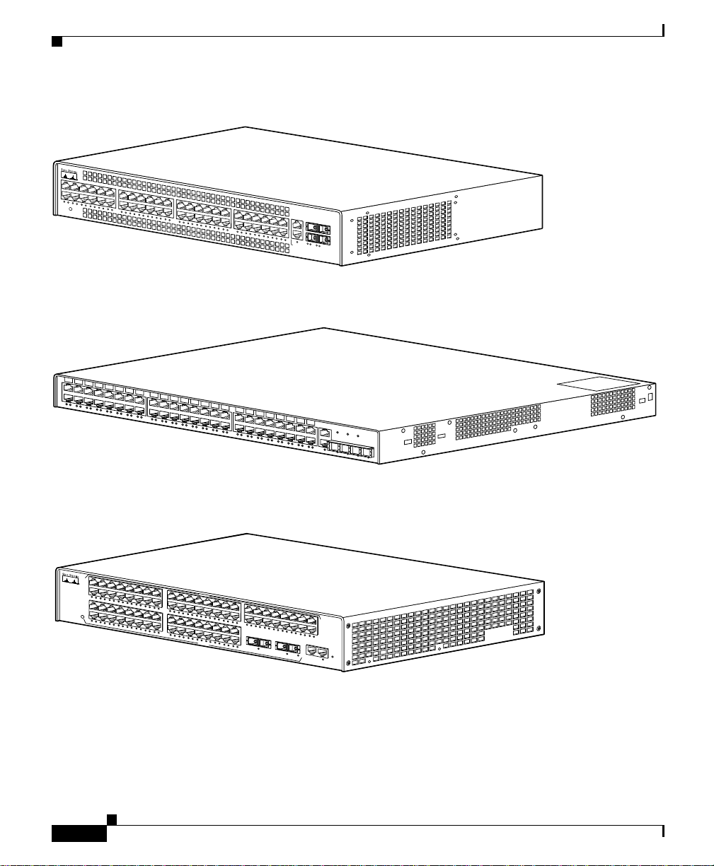
The Catalyst 2948G, 2948G -GE-TX , and 2980G switche s are designed for
high-performance , hig h-d en sity wi ring -clo set ap pli cat ions. Figu re 1-1 through
Figure 1-3 show the switches.
CHAPTER
1
78-6286-05
Catalyst 2984G, 2948G-GE-TX, and 2980G Switch Hardware Installation Guide
1-1
Page 30
Switch Description
Figure 1-1 Catalyst 2948G Switch
STATUS
Catalyst 2948G
C
O
N
S
10
B
a
Figure 1-2 Catalyst 2948G-GE-TX Switch
Chapter 1 Product Overview
O
L
E
1
0
0
0
B
as
e
-
X
se
T
98431
98434
Figure 1-3 Catalyst 2980G Switch
1
2
1
2
3
4
5
1
6
7
8
9
10
11
12
13
14
15
STATUS
2
1
0
/
1
0
0
/
1
0
0
0
E
T
H
E
R
E
N
E
T
1
2
3
4
5
6
16
7
8
9
1
0
1
1
1
2
1
3
1
4
1
5
1
SLOT 2
1
7
1
8
1
9
2
0
2
1
2
2
2
3
2
4
2
5
2
6
2
7
2
8
2
9
3
0
3
1
3
2
3
3
3
4
3
6
1
7
1
8
1
9
2
0
2
1
2
2
2
3
2
SLOT 3
1
4
2
5
2
6
2
7
3
2
2
8
2
9
3
0
3
1
3
2
The Catalyst 2948G, 2948G -GE-TX , and 2980G swit ches interfac e with
networking equipment using Ethernet (10BASE-T), Fast Ethernet (100BASE-T),
and Gigabit Ethernet (1000 BASE-T) interface s. Depen ding on the model, the
switches also support Gigabit Interface Converters (GBICs) or sm all form-factor
pluggable (SFP) modules.
Catalyst 2984G, 2948G-GE-TX, and 2980G Switch Hardware Installation Guide
1-2
C
A
T
A
L
Y
S
T
2
4
9
7
3
5
3
6
3
7
3
8
3
9
4
0
4
1
4
2
4
3
4
4
3
3
3
4
P
86
4
8
4
5
4
6
4
7
4
8
C
O
N
S
O
L
E
1
0
M
B
M
G
T
R
E
S
E
T
W
R
50747
78-6286-05
Page 31

Chapter 1 Product Overview
The Catalyst 2948G switch has 48 autosensi ng and auto configuring
10/100BASE-T Fast Ethernet fixed ports. The Catalyst 2948G-GE-TX switch has
48 autosensing and autoconfiguring 10/ 100/100 0BASE-T ports. The
Catalyst 2980G switch has 80 autosensing a nd autoco nfiguring 10/10 0BASE-T
Fast Ethernet fixed ports.
GBIC Module Suppor t
The Catalyst 2948G and 2980G switche s each have two Gigabit Ethernet uplink
ports with modular Gigabit Interface Converters (GBICs).
A GBIC is a hot-swappable input/output device that plugs into a Gigabit Ethernet
port module and links the port module with a fiber-optic network. For a detailed
description of Gigabit Et hernet ports, s ee the “GBIC Features” section on
page 4-2.
For a complete list of supported GBIC modules, see Table 4-1 on pag e 4-3.
Note The Catalyst 2948G-GE- TX switc h does not suppo rt GBIC modul es.
Switch Description
The Gigabit Ethernet port s can be con figured with a ny combinati on of GBIC
types.
The Gigabit Ethernet ports on these modules are used primarily for backbone
interconnection of ot her high- pe rform an ce s witc hes a nd rout er s.
SFP Module Support
The Catalyst 2948G-GE-TX switch has four small form-factor pluggable (SFP)
module slots. The switch uses SFP modules to establish Gigabit connections. The
SFP module slots are located on the front of the switch.
An SFP module is a hot-swappable input/output device that plugs into an SFP
module slot, linking the port mo dule with a fiber-optic net work.
For a list of SFP modules supported by the Catalyst 2948G-GE-TX switch, see
Table 4-4 on page 4-12.
Catalyst 2984G, 2948G-GE-TX, and 2980G Switch Hardware Installation Guide
78-6286-05
1-3
Page 32

Switch Description
Note Catalyst 2948G-GE-TX sw itch only sup ports 1000 Mb ps and full-du plex modes
on SFP modules.
Except for the 1000BASE-T SFP module, all of the SFP modules are used to
establish fiber-optic conne ct ions. You use fiber-optic cables with Lucent (L C)
connectors to connect to an SFP module. The SFP modules support 850 to 1550
nanometer nom ina l wave lengths. T he se field- repl ace abl e mo dul es p rovid e the
uplink optical interfaces, laser send (TX) and laser receive (RX). For a detailed
description of Gigabit Et hernet ports see the “Connecting To an SFP Module”
section on page 4-12.
Switch Features
Table 1-1 describes the Catalyst 294 8G, 2948G -GE-TX, and 2980G s witch
features.
Table 1-1 Catalyst 2948G, 2948G-GE-TX, and 2980G Switch Features
Chapter 1 Product Overview
Feature Description
Ethernet spee ds
• Ethernet (10 BASE-T) i nte rface to work stat ions a nd re pe ate rs
• Fast Ethernet (100BASE-T) interface to workstations, servers,
switches, and routers
Note Autonegotiation of li nk spee d on ea ch 1 0/ 100 a nd 10 /100/1 000
port allows migration to 100BASE-T or 1000BASE-T from a
10BASE-T or 100BASE-T installed base.
• Gigabit Etherne t (1 000 BASE-T) c opp er a nd Gi gab it Ethe rn et
(1000BASE-X) fiber-optic interface for back bon e in te rcon ne ction o f
high-performan ce swit ches and rou ters
Standard management and
support
Catalyst 2984G, 2948G-GE-TX, and 2980G Switch Hardware Installation Guide
• Layer 2 forward ing with an ag gre gat e fo rw ardi ng r ate of grea ter th an
17.8 million packets per second
• 16,000 MAC addresses per system
1-4
78-6286-05
Page 33

Chapter 1 Product Overview
Table 1-1 Catalyst 2948G, 2948G-GE-TX, and 2980G Switch Features (continued)
Feature Description
Standard management and
support (continued)
Software man agem en t
• Up to 1,024 VLANs with IE EE 802.1Q VLAN tagg ing on all por ts
and support for V TP
• Port aggregation using PAgP
1
2
for 100-Mbps and 1-Gbps
EtherChannel
3
• CLI
and SNMP interfaces consisten t with the Cata lyst 4500 seri es
and 6500 family swit ches
• Development of new features compatible with the Catalyst 6500
family switches
• Out-of-band mana ge ment t hro ugh t he R J-45 10 BASE-T co nsole
serial port
• 10BASE-T out-of-band management and in-band management
through any switch port with SNMP, Telnet client, and TFTP
Note The Catalyst 2948G- GE- TX and 29 80G- A sw itche s have a
10/100BASE-T management port.
Switch Description
78-6286-05
• RMON
• Standard Layer 2 elements:
Catalyst 2984G, 2948G-GE-TX, and 2980G Switch Hardware Installation Guide
4
with RMON 1
–
802.1D Spanning Tree
–
–
–
5
CDP
VTP6 version 2 with pr unin g exte nsions
CGMP7 client
1-5
Page 34

Chapter 1 Product Overview
Switch Description
Table 1-1 Catalyst 2948G, 2948G-GE-TX, and 2980G Switch Features (continued)
Feature Description
Embedded mana geme nt
Power supplies
1. VTP = VLAN Trunking Protocol
2. PAgP = Port Aggregation Protocol
3. CLI = command-line interface
4. RMON = Remote Monitoring
5. CDP = Cisco Discovery Protocol
6. VTP = Virtual Terminal Protocol
7. CGMP = Cisco Group Management Protocol
• Full SNMP implementation, including entity-MIB, all relevant
standard MIBs, a nd all r elevant Cisco M IBs
• The first four RMON groups (Ether net sta tistics, Ala rms, Ev ents, an d
History) supported on a per port basis without an opti onal RMON
processing module
• Redirection of tra ffic from any por t to a “sn iff” port. (Any sw it chi ng
port can be designate d as a “sniff” port .)
• Performance manage ment infor mation
• 120 W AC internal power supply on the Catalyst 2948G switch
• 156 W AC internal power supply on the Catalyst 2948G-GE-TX
switch
• 175 W AC internal power supply on the Catalyst 2980G switch
Port Locations
This section desc ribe s the port loc atio ns a nd numb er ing on the sw itche s.
10/100 and 10/100/1000 Ports
The 10/100 and 10 /100/ 1 000 ports a re c onfigu red i n vertic al pai rs. Ea ch vert ica l
pair has two Link Status LEDs below it. The LE D on the left is for the top por t;
the LED on the right is for the bottom port. For example, LED 1 is for the upper
port (port 1) and LE D 2 is for the b ott om por t ( por t 2) .
Catalyst 2984G, 2948G-GE-TX, and 2980G Switch Hardware Installation Guide
1-6
78-6286-05
Page 35

Chapter 1 Product Overview
Catalyst 2948G and 2980G Switch Ports
The Catalyst 2948G switch 10/100BASE-T ports are configured in two rows. The
top row contains odd-numbered ports (1 through 47), and the bottom row contains
even-numbered ports (2 thr oug h 48) .
The Catalyst 2980G switch 10/100BASE-T ports are configured in four rows. The
top two rows are numbe red 1 th roug h 4 8, wi th the first row odd-nu mb er ed (1
through 47) an d the secon d r ow even-number ed ( 2 t hrou gh 48) . Th e bot tom t wo
rows are numbered 1 through 32, with the first row odd-numbered (1 through 31)
and the second row even-numbered (2 through 32) .
Two GBIC ports are a t the r ight of the fr ont pane l on t he C ata lyst 2948G an d
Catalyst 2980G switches:
• On the Catalyst 2948G switches, these ports are located at the far right of th e
front panel. Th e up pe r Gi gabi t Eth er ne t por t i s p ort 49; t h e lower is po rt 5 0.
The Link Status L E Ds fo r th ese po rts are bel ow port 50.
• On the Catalyst 2980G swi tch es, the GB IC Et hern et por ts a re loc ated
immediately to the right of ports 3 1 and 32. The port on the left is port 3 3; the
port on the right is port 34. The L ink Status LE Ds for th e Gigabit Ethern et
ports are located below each port.
Switch Components
Catalyst 2948G-GE-TX Switch Ports
The Catalyst 2948G-GE- TX 10/10 0/1000BASE-T Gi gabit Eth ernet port s are
configured in two rows. The top row contains odd-numbered ports (1 through 47),
and the bottom row contains even-numbered por ts (2 throug h 48).
The SFP module slots are numbered left to right 49 throug h 52.
Switch Components
This section describes the fo llowing Catalyst 2948G and 2980 G switch
components:
• Management Ports, page 8
• Front Panel LEDs, page 8
Catalyst 2984G, 2948G-GE-TX, and 2980G Switch Hardware Installation Guide
78-6286-05
1-7
Page 36

Switch Components
• Airflow, page 9
• Power Supplies, page 11
Management Ports
The Catalyst 2948G, 2948G-G E-TX, and 2980G switche s have two kinds of
management ports: consol e serial and Ethernet . The Catal yst 2948G swi tches
have a 10BASE-T management port. The Catalyst 2948 G-GE-TX and 2 980G-A
switches have a 10/100BASE-T management port.
Table 1-2 on page 1-9 lists the management options for the switches.
Console Serial Port
An RJ-45 console serial port allows you to perform switch-management functions
using a terminal. See Table A-1 on page A-1 for the console co nnecto r pinouts .
10BASE-T and 10/100BASE-T Ports
Chapter 1 Product Overview
An RJ-45 10BASE-T port a llows you to pe r form TCP/I P sw it ch-ma nage ment
functions (Telnet, SNMP, FTP), configur e IP addresse s with BOOTP, and
download software images.
Note The Catalyst 2948G-GE- TX an d 2980G -A switches have a 10/100BASE-T
management port.
This port is for network management only; it is not for switching. Connecti vity is
not available between this port and the 10/10 0BASE-T switch ing ports.
Front Panel LEDs
The LEDs on the front panels of the Catalyst 2948G, 2948G-GE-TX, and 2980G
switches perform the following functions:
• STATUS LEDs indicate the operating state of the switches.
• Link Status LEDs pr ovide man agem ent a nd indic ate sw itch ing por t sta tus.
Catalyst 2984G, 2948G-GE-TX, and 2980G Switch Hardware Installation Guide
1-8
78-6286-05
Page 37

Chapter 1 Product Overview
Switch Components
• PSI LED indicates the internal power supply status on the Cata lyst 2948G
switch.
• PWR LED indicates the inte rnal p ower supply stat us on t he C ata lyst 2980G
switch.
• RPS LED provides the external redundant power supply stat us.
Table 1-2 describes the LEDs.
Table 1-2 Front Pa nel LEDs
LED Color/Statue Description
STATUS Indicates the results of a series of self-test diagnostics.
Green
Red
Amber
Off
Link Status Indicates the link stat us of a port.
Green
Amber
Flashing
Off
PSI, PWR, and RPS Indicates power supply operation or failure.
Green
Amber
All tests pass.
A test other than an individual por t test fails.
System boot or diag nostic te sts in pr ogr ess.
Switch is disabled .
Port is operational .
Port is disabled by us er.
Power-on self-test indicates faulty port.
No signal detected, or link configuration failure.
Power supply is operational.
Power supply has failed or is in Standby mode.
Airflow
78-6286-05
Note For environmental specifications, see Chapter 2, “Site Planning.”
On the Catalyst 2948G and 2980G switches, th e system fan assemb ly provides
cooling air for the internal chassis components. The fans exhaust warm air from
one end and dr aw in cool ai r at the o ther en d.
Catalyst 2984G, 2948G-GE-TX, and 2980G Switch Hardware Installation Guide
1-9
Page 38

Switch Components
If an individual fan fails, the othe r fans co ntinue to ru n. Sensor s m onit or t he
internal air tempera t u re s. I f t he air temperature exc eed s a tolerable thresh old , th e
environmental monitor displays warning messages.
On the Catalyst 2948G-GE-TX, a blower system draws cool air in from the fro nt
and sides of the switch and exhausts air ou t the back.
Figure 1-4 shows the direction of airflow through the Catalyst 2 948G switch.
Figure 1-5 shows the direction of airflow through the Catalyst 2948G-GE-TX
switch.
Figure 1-6 shows the direction of airflow through the Catalyst 2 980G switch.
Figure 1-4 Catalyst 2948G Airflow
STATUS
Catalyst 2948G
Chapter 1 Product Overview
C
O
N
S
O
L
E
1
0
0
0
B
a
s
e
- X
1
0
B
a
s
e
T
98432
Figure 1-5 Catalyst 2948G-GE-TX Airflow
Catalyst 2984G, 2948G-GE-TX, and 2980G Switch Hardware Installation Guide
1-10
98720
78-6286-05
Page 39

Chapter 1 Product Overview
Figure 1-6 Catalyst 2980G Airflow
1
2
1
2
3
4
5
1
6
7
8
9
10
11
12
13
14
15
STATUS
2
1
0
/
1
0
0
/
1
0
0
0
E
T
H
E
R
E
N
E
T
1
2
3
4
5
6
16
7
8
9
1
0
1
1
1
2
1
3
1
4
1
5
1
SLOT 2
1
7
1
8
1
9
2
0
2
1
2
2
2
3
2
4
2
5
2
6
2
7
2
8
2
9
3
0
3
1
3
6
1
7
1
8
1
9
2
0
2
1
2
2
2
2
3
2
4
2
5
2
SLOT 3
6
2
7
2
8
2
9
3
0
3
1
3
2
Power Supplies
There is no power switch on the switches. AC power is present in the power
supply when the p ower cord is pl ugg ed i n.
The environmental monitoring and reporting functions allow you to maintain
normal system op er ation by corr ec ting ad verse environmenta l c ond ition s b ef ore
loss of operation.
Switch Components
C
A
T
A
L
Y
S
T 2
4
9
7
8
3
3
3
4
3
3
1
5
3
6
3
7
3
8
3
9
4
0
4
1
4
2
4
3
4
3
2
4
3
3
3
4
P
6
4
8
4
5
4
6
4
7
4
8
C
O
N
S
O
L
E
1
0
M
B
M
G
T
R
E
S
E
T
W
R
32064
78-6286-05
Each po wer supply monitors its ow n temperat ure and output v oltage s. If the p ower
supply becomes excessively hot, it shut s down to prevent damag e. T he swi tch es
monitor the oper at ing cond iti on of t h e power supp ly a nd re po rt t he status usi ng
switch software.
The switches have the following power supplies:
• 120 W AC internal power supply—Cata lyst 2948 G switch
• 156 W AC internal power supply—C atal yst 2 948G- GE-T X sw itch
• 175 W AC internal power supply—Cata lyst 2980 G switch
• 156 W AC internal power supply—Cata lyst 2980 G-A swi tch
Note For complete power specifications for the Ca talyst 2948G, 294 8G-G E-TX,
and 2980G switches, see A pp end ix A, “ Spe cificat ions. ”
These switches also be used with an opti onal Cisco Redun dant Power System
(RPS).
Catalyst 2984G, 2948G-GE-TX, and 2980G Switch Hardware Installation Guide
1-11
Page 40

Switch Components
Chapter 1 Product Overview
• The Catalyst 2948G switch uses the Cisco RPS 600 AC power supply
(PWR600-AC-RPS-CAB).
The Cisco RPS 60 0 s uppo rts fou r exte rnal devices t hat us e up t o 150 W DC
each. Use a one-to-one cable (one connector at each cable end) to connect
four external devices to t he f our DC out pu t power mo dul es.
The power source is part ia lly redu nda nt. The re are two AC input power
modules for the Cisco RPS and one DC ou tput power module fo r each
external dev ice. The A C input to the Cisco RPS is fully redundant, b ut the DC
output to the external devices is not.
Warning
Warning
Attach only the Cisco RPS (model PWR600-AC-RPS) to the RPS receptacle.
Statement 112
• The Catalyst 2948G-GE- TX switch use s the Cisco RPS 675 (model
PWR675-AC-RPS-N1).
The RPS 675 supports six external network devices an d provides DC power
to one failed device at a time. It automatically senses when the internal p ower
supply of a connected device fails and provide s power to that device, which
prevents loss of network traffic.
Attach only the Cisco RPS (model PWR675-AC-RPS-N1=) to the RPS receptacle.
Statement 100C
• The Catalyst 2980G-A swit ch uses the Cisco RPS 300
(PWR300-AC-RPS-N1).
The RPS 300 supports six external network devices and provid es power to
one failed de vi ce at a tim e. I t a utom atic ally senses when the po we r sup ply of
a connected device fails and provides the necessary power to the failed device
to prevent loss of network traffic. When the internal power supply of the
device has been brought up or replaced, the RPS auto matica lly stops
powering the device.
1-12
Warning
Catalyst 2984G, 2948G-GE-TX, and 2980G Switch Hardware Installation Guide
Attach only the Cisco RPS (model PWR300-AC-RPS-N1) to the RPS receptacle.
Statement 100B
78-6286-05
Page 41

Chapter 1 Product Overview
A Cisco RPS can only power one switch at a time. If more than one switch fails
at the same time, any subsequ ent switch is not supported b y the RPS until th e first
switch failure is resolved. For more information, refer to the documentation that
was included with your RPS.
On the Catalyst 2948G switch , you must use a Y cable to connect the switch to
two RPS 600 power supplies. Each RPS 600 has status LEDs (PSI and RPS).
On the Catalyst 2980G-A switch , each RPS 300 power supply has an individua l
power cord and has status LEDs (PSI, PWR, and RPS).
The RPS uses redundant power supplies. If one of the power supplies in the RPS
fails, the RPS will automatically switch over to the other power supply without
forcing the switch to reb oot.
Note On the Catalyst 2948G-GE- TX and 2948 G switche s, only one power source can
supply power to the switch at a ny one time . W hen you ar e u sin g an RPS, unp lug
the local power cord for the switch. If you are using the local power supply, the
RPS can be connected but must not be powered on. The switches can be powered
by both the internal power supply and the RPS at the same time .
Switch Components
78-6286-05
Catalyst 2984G, 2948G-GE-TX, and 2980G Switch Hardware Installation Guide
1-13
Page 42

Switch Components
Chapter 1 Product Overview
1-14
Catalyst 2984G, 2948G-GE-TX, and 2980G Switch Hardware Installation Guide
78-6286-05
Page 43

Warning
Warning
CHAPTER
2
Site Planning
Before you install, operate, or service the system, read the Site Preparation and
Safety Guide. This guide contains important safety information you should know
before working with the system.
Only trained and qualified personnel should be allowed to install, replace, or
service this equipment.
This chapter describes how to prep are yo ur site for the in stallati on of your switc h
and contains the se sect ion s:
• Site Power Requirements and Heat Dissi pati on, p age 2
• System Ground Connection Guidelines (Catalyst 2948G and 2980G Switches
Only), page 3
Statement 1030
Statement 200
78-6286-05
• Site-Planning Checklist, page 7
Note See the “Site-Planning Checklist” section on page 7 to help ensure that you
complete all site-planning activities before you install the switch.
Catalyst 2984G, 2948G-GE-TX, and 2980G Switch Hardware Installation Guide
2-1
Page 44

Chapter2 Site Planning
Site Power Requirements and Heat D issi pation
Site Power Requirements and Heat Dissipation
Note Catalyst 2948G, 2948G-G E-TX , and 2980G s witc hes have in t erna l power
supplies. All of the switc hes su ppo rt Cisc o Redun dant Power Syste m (RPS) fo r
redundant operatio n.
This section provides site power require ments and heat dissipation specif ic ations
for the Catalyst 2948G , 2948G -GE- TX, and 2980G swi tc hes . You should verify
site power before you install a switch.
Power requirements can vary for each Catalyst switch. Knowing the power
requirements can be use fu l for plan ning t he power dis tri bution syste m nee ded t o
support the switches. Heat specifications are used for determining the
air-conditioning requirements for an installation.
Note Refer to the Site Preparation and Safet y Guide for site power requi rements,
preinstallation re quirem ent s, and EM I reco mmen dation s.
Table 2-1 describes t he po wer requi rements and heat di ssipati on specif ication s for
the Catalyst 2948G, 2948G -GE -TX, a nd 2980G sw itches .
Table 2-1 Pow er Requi rements and Heat Dissipation Specifications
Power
Supply
Model Number/
Module Type
Catalyst 2948G switch 120 200 645 90 VAC: 2.0
Catalyst 2948G-GE-TX switch 156 130 445 100 VAC: 1.5
Catalyst 2984G, 2948G-GE-TX, and 2980G Switch Hardware Installation Guide
2-2
Output
(Watts)
AC Input
Power
(Watts)
Heat Diss
(BTU/Hr) AC Input Current (Amps)
120 VAC: 1.6
180 VAC: 1.0
240 VAC: 0.9
240 VAC: 0.8
78-6286-05
Page 45

Chapter 2 Site Planning
System Ground Connection Guidelines (Catalyst 2948G and 2980G Switches Only)
Table 2-1 Pow er Requi rements and Heat Dissipation Specifications (continued)
Power
Supply
Model Number/
Module Type
Catalyst 2980G switch 175 300 950 90 VAC: 3.0
Catalyst 2980G-A switch 156 208 670 90 VAC: 2.3
Output
(Watts)
AC Input
Power
(Watts)
Heat Diss
(BTU/Hr) AC Input Current (Amps)
120 VAC: 2.4
180 VAC: 1.6
240 VAC: 1.0
120 VAC: 1.7
180 VAC: 1.1
240 VAC: 0.9
System Ground Connection Guidelines
(Catalyst 2948G and 2980G Switches Only)
78-6286-05
Two system (earth) grounding holes are provided in an enclosure near the power
supplies.
Note These guidelines do not apply to the Catal yst 2948G-G E-TX sw itches.
See Figure 2-1 for the location of t he gro undin g h ole s on the C ata lyst 2948 G
switches and Figure 2-2 for the location on the Catalyst 2980G switches.
Catalyst 2984G, 2948G-GE-TX, and 2980G Switch Hardware Installation Guide
2-3
Page 46

System Ground Connec ti on Guidelines (Catalyst 2948G and 2980G Switches Only)
Figure 2-1 Grounding Holes on the Catalyst 2948G Switch
M4 screw holes (2)
Figure 2-2 Grounding Holes on the Catalyst 2980G Switch
Chapter2 Site Planning
33110
33109
2-4
M4 screw holes (2)
To make an adeq uate g roundi n g c on nect ion , y ou nee d the se c om ponen ts a nd
tools:
• Grounding lug—The gro und ing l ug m ust have two M4 screw hol es. Se e
Figure 2-1 for the location of the M4 screw holes on the Catalyst 2948G
switch and Figure 2-2 for the Catalyst 2980G switch.
The grounding lugs are not available from Cisc o Systems; any
electrical-c onnect or vendor ca n provide thi s lug.
• Two M4 (metric) hex-head screws with locking washers—These screws are
not available from Cisco Systems; they are available from any commercial
hardware vendor.
• One grounding wi re ( 6 AWG recommended)—The leng th o f the gr oun ding
wires depends on the location of your switch within the site and its proximity
to proper grounding facilitie s. The grounding wire is not av ailable from Cisco
Systems; it is available from any commercial cable vendor.
Catalyst 2984G, 2948G-GE-TX, and 2980G Switch Hardware Installation Guide
78-6286-05
Page 47

Chapter 2 Site Planning
System Ground Connection Guidelines (Catalyst 2948G and 2980G Switches Only)
• Number 2 Phillips head screwdriver.
• Crimping tool—This must be large enough to accommod ate the girt h of the
grounding lug when you cr imp the groun ding cab le into the lug.
• Wire-stripping tool.
Connecting the Switch to Earth Ground
This procedure des crib es how to connect the Ca talyst 2948G , 2948G-G E-TX,
and 2980G switches to eart h gro und. We strongly recommend th at yo u com ple te
this procedure be for e c onn ect ing syste m p ower or turnin g o n y our swit ch.
T o attach the grounding lug and cable to the grounding pad on the Catalyst 2948G,
2948G-GE-TX, and 2980G swit ches, fo llow these steps :
Step 1 Use a wire-st rippi ng tool to rem ove approxima tely 0.75 inche s (19 mm) of the
covering from the end of the groundi ng wire.
Step 2 Insert the strip ped end of the ground ing wire int o the open en d of the groun ding
lug.
78-6286-05
Step 3 Use the crimping tool to secure the grounding wire in pl ace in the grounding lug.
Step 4 Locate the grou nding pad on th e switch.
See Figu re 2-3 for the location of the grounding pad on the Catalyst 2948G switch
and Figure 2-4 for the Catalyst 2980G switch.
Catalyst 2984G, 2948G-GE-TX, and 2980G Switch Hardware Installation Guide
2-5
Page 48

System Ground Connec ti on Guidelines (Catalyst 2948G and 2980G Switches Only)
Figure 2-3 Connecting System Ground on the Catalyst 2948G Switch
Wire
Grounding
Screws
Grounding lug
Figure 2-4 Connecting System Ground on the Catalyst 2980G Switch
pad
Chapter2 Site Planning
33112
2-6
33111
Wire
Grounding
pad
Step 5
Screws
Grounding lug
Remove the label that covers th e gr oun ding pa d.
Step 6 Place the grounding lug against the grounding pad on the rear panel of the switch.
Step 7 Install locking washers; tighten them to secure the grounding lug to the grounding
pad.
Step 8 Insert two scr ews throu gh the hole s i n t he g rou nding l ug and the gr oun ding pad.
Ensure that the grounding lug and the attached wire will not interfere with other
switch hardware or rack equipme nt.
Catalyst 2984G, 2948G-GE-TX, and 2980G Switch Hardware Installation Guide
78-6286-05
Page 49

Chapter 2 Site Planning
Site-Planning Checklist
Step 9 Prepare the othe r end of the gr oundi ng wire and co nnect it to an appr opriate
grounding point at your site to ensure adeq uate eart h ground for the switch .
Site-Planning Checklist
Table 2-2 lists the site-planning activities that you should complete before you
install the Catalyst 2948G, 2948G-GE-TX, and 2980G switches. Completing
each activity helps ensure a successful switch installation.
Table 2-2 Site-Planning Checklist
Task No. Planning Activity Verified By Time Date
1 Space evaluation:
Space and layout
Floor covering
Impact and vibr ati on
Lighting
Maintenance access
2 Environmental evaluation:
Ambient temperature
Humidity
Altitude
Atmospheric contamination
Airflow
3 Power evaluation:
Input power type
Proximity of rec ept acle to t he e quipm en t
Dedicated (sepa rat e) c irc uit s fo r redun da nt p ower suppl ies
UPS for power failures
4 Grounding evaluation:
Circuit breaker size
Catalyst 2984G, 2948G-GE-TX, and 2980G Switch Hardware Installation Guide
78-6286-05
2-7
Page 50

Chapter2 Site Planning
Site-Planning Checklist
Table 2-2 Site-Planning Checklist (continued)
Task No. Planning Activity Verified By Time Date
5 Cable and interface equipment evaluation:
Cable type
Connector type
Cable distance limitations
Interface equipment (transceivers)
6EMI evaluation:
Distance limitations for signaling
Site wiring
RFI levels
2-8
Catalyst 2984G, 2948G-GE-TX, and 2980G Switch Hardware Installation Guide
78-6286-05
Page 51

Warning
Warning
CHAPTER
3
Installing the Switch
Before you install, operate, or service the system, read the Site Preparation and
Safety Guide. This guide contains important safety information you should know
before working with the system.
Only trained and qualified personnel should be allowed to install, replace, or
service this equipment.
This chapter desc rib es how to inst all the Cata lyst 2948G, 29 48G- GE-TX ,
and 2980G switches. For first-time installations, perform the procedures in these
sections in the order listed:
• Preparing for Installation, page 2
Statement 1030
Statement 200
78-6286-05
• Installing the Catalyst 2948G and 2980G Switche s, page 6
• Installing the Catalyst 2948G -GE-TX Sw itch, page 9
• Connecting Power to the Switches, page 19
• Connecting a Terminal to the Console Serial and Ethernet Management Ports,
page 22
Note Before starting the installation procedures in this chapter, complete the
site-planning checklist in Chapter 2, “Site Planning.”
Catalyst 2984G, 2948G-GE-TX, and 2980G Switch Hardware Installation Guide
3-1
Page 52

Preparing for Instal la t io n
Preparing for Installation
This section provides infor mati on about th ese topics :
• EMC Regulatory Statements, page 2
• Checking the Shipping Container, page 4
EMC Regulatory Statements
This section includes specific regulatory statements about the switches.
U.S.A.
U.S. regulatory information for this product is in the front matter of this manual.
Taiwan
Chapter 3 Installing the Switch
3-2
Warning
Catalyst 2984G, 2948G-GE-TX, and 2980G Switch Hardware Installation Guide
This is a Class A Information Product, when used in residential environment,
it may cause radio frequency interference, under such circumstances, the
user may be requested to take appropriate countermeasures.
78-6286-05
Page 53
Chapter 3 Installing the Switch
VCCI Class A Notice for Japan
Preparing for Installation
Korea
Warning
Warning
This is a Class A product based on the standard of the Voluntary Control
Council for Interference by Information Technology Equipment (VCCI). If this
equipment is used in a domestic environment, radio disturbance may arise.
When such trouble occurs, the user may be required to take corrective
actions.
This is a Class A Device and is registered for EMC requirements for industrial
use. The seller or buyer should be aware of this. If this type was sold or
purchased by mistake, it should be replaced with a residential-use type.
78-6286-05
Catalyst 2984G, 2948G-GE-TX, and 2980G Switch Hardware Installation Guide
3-3
Page 54

Preparing for Instal la t io n
Class A Notice for Hungary
Chapter 3 Installing the Switch
Warning
This equipment is a class A product and should be used and installed properly
according to the Hungarian EMC Class A requirements (MSZEN55022). Class A
equipment is designed for typical commercial establishments for which
special conditions of installation and protection distance are used.
Checking the Shipping Container
Do not discard the p acking c art on an d ot her pac kin g m ate ria ls a fter you un pa ck
the switch. Flatten the packing carton and store it. You will need the packing
materials if you need to move or ship the switch in the future. Repacking
instructions are provided in Appendix B, “Rep ackin g a Switc h.”
Check the contents of the accessory kit against the accessories checklist and the
packing slip. Verify that you received all listed equipment.
Catalyst 2948G and 2980G Switches
The Catalyst 2948G and 2980G s witches are shi pped with the se items:
• This hardware gui de
• AC power cord
• RJ-45 to DB-9 cable
• DB-9 to RJ-45 ca ble
Catalyst 2984G, 2948G-GE-TX, and 2980G Switch Hardware Installation Guide
3-4
78-6286-05
Page 55

Chapter 3 Installing the Switch
• ESD wrist strap
• Mounting kit
Catalyst 2948G-GE-TX Switches
The Catalys t 294 8G -GE- TX s witc h is ship ped with th ese ite ms:
• This hardware guid e
• About the Catalyst 2948G Do cument ation flye r
• AC power cord
• One RJ-45-to-DB-9 adapte r cable (78-3383-X X)
• Mounting kit containing:
–
Four rubber feet for mounting th e switch on a table (5 1-0089)
–
Two 19-inch rack-mou nting bra ckets ( 700- 08 209-X X)
–
Four Phillips machine screws for attaching the brackets to a rack
(48-0655-XX)
–
One cable guide (700-05613 -XX)
Preparing for Installation
78-6286-05
–
One black Phillips machine scre w for attachin g the cable gui de to one of
the mounting bra ckets (48 -0654- X X)
–
One Redundant Power System (RPS) connector cover for wall mounting
(700-16465-XX)
–
T w o Phillips pa n-head screws for attaching the RPS cover (48-0482-XX)
–
Four Phillips truss-head screws for attaching wall-mounting b rackets
(48-0656-XX)
–
Four Phillips pan-head screws for attaching the switch to a rack
(48-0523-XX)
Catalyst 2984G, 2948G-GE-TX, and 2980G Switch Hardware Installation Guide
3-5
Page 56

Chapter 3 Installing the Switch
Installing the Catalyst 2948G and 2980G Switches
Installing the Catalyst 2948G and 2980G Switches
Warning
To prevent bodily injury when mounting or servicing this unit in a rack, you
must take special precautions to ensure that the system remains stable. The
following guidelines are provided to ensure your safety:
• This unit should be mounted at the bottom of the rack if it is the only unit i n the rack.
• When mounting this unit in a partially filled rack, load the rack from the bottom to the
top with the heaviest component at the bottom of the rack.
• If the rack is provided with stabilizing devices, install the stabilizers before mounting
or servicing the uni t in the rack.
A standard rack-m ou nt k it is i ncl uded for m ount ing t he sw itch in a
standard 19-inch (48.3 cm) equipm ent rac k with two unobstr ucted oute r posts.
This kit is not suitable for racks with obstructions (such as a power strip) that
could impair access to the switch.
Required Installati on To ols
You will need the following tools and equipment to install the switc h chassis in a
rack:
• Rack-mount kit
Statement 1006
3-6
• Tape measure and level
• Number 1 Phillips, number 2 Phillips, or a 3/16-inch flat-blade screwdriver
• Antistatic mat or antistatic foam
• Your own ele ctr osta tic d isch arge (E SD) grou nding st rap or the disp osabl e
ESD strap included with the switch
Note For more information about ESD, refer to the Site Preparation and Safety Guide.
Catalyst 2984G, 2948G-GE-TX, and 2980G Switch Hardware Installation Guide
78-6286-05
Page 57

Chapter 3 Installing the Switch
Installing the Catalyst 2948G and 2980G Switches
Rack-Mounting the Catalyst 2948G and 2980G Switches
To install Catalyst 2940G and 2980G switches in a 19-inch rack, follow these
steps:
Step 1 Prepare for installation as follows:
a. Place the chassis on the floor or on a sturdy table, as close as possible to the
rack. Leave enough clearance to allow yourself to move around the chassis.
b. Use the tape measure to measure the depth of the rack. Measure from the
outside of the front-moun ting posts to the outside of the rear-mount ing strip.
The depth must be at least 19. 25 inches (48. 9 cm) and not greater th an
32 inches (81.3 cm).
c. Measure the sp ac e be twe en t he i nn er e dges of th e l eft fr ont - an d r ight fr ont-
mounting posts to ensure that it is 17.75 inches (45.09 cm) wide. (The chassis
is 17.5 inches [44 cm] wide and mus t fit between the mou nting pos ts. See
Figure 3-2.)
d. Open the rack-mount kit and refer to th e c omp on en t ch ecklis t in Table 3-1 to
verify that all parts are i nclude d.
78-6286-05
Table 3-1 Rack-Mount Kit Checklist
Part Description Quantity
L brackets 2
M4 Phillips pan-head screws 4
12-24 x 3/4-inch Phillips binder-head screws 6
Note Some equipment racks have a power strip along the length of one of the rear posts.
If the rack has this feature, consider the position of the strip when planning
fastener point s. Before inst alling the L br ackets on th e chassis, d etermine whether
to install the chassis from the front or the rear of the rack.
Step 2 Attach the left and right L brackets using the four M4 Phillips pan-head screws
provided in the rack-mount kit (see Figure 3-1).
Catalyst 2984G, 2948G-GE-TX, and 2980G Switch Hardware Installation Guide
3-7
Page 58

Installing the Catalyst 2948G and 2980G Switches
The L brackets con nect the sw itch chass is to the rack . You can mount the
L brackets to the front- or rear-mounting holes of the chassis, depending on which
end is in the front of the rac k.
Note The Catalyst 2948G switch is shown in the rack-mounting illustrations.
The rack-mounting pro cedur e for the Cata lyst 2980 G switc h is the sa me.
Figure 3-1 Attaching the L Brackets
STATUS
Catalyst 2948G
Chapter 3 Installing the Switch
C
O
N
S
O
L
E
1
0
0
0
B
a
s
e
- X
1
0
B
a
s
e
T
98435
3-8
Step 3
Figure 3-2 shows how to attach the front of the switch to the rack. You can also
attach the rear of the switch to the rack, depending on the configuration of your
rack.
Install the chassis in the rack as follows:
a. Position the switch chassis in the rack (see Figure 3-2):
• If the chassis front panel is to be in the front of the rack, insert the rear
of the chassis between the mounting posts.
• If the rear of the chassis is to be in the front of the rack, insert the front
of the chassis between the mounting posts.
b. Align the mounting holes in the L bracket with the mounting holes in the
equipment rack.
c. Secure the chassis using six 12-24 x 3/4-inch screws (three per side) through
the elongated holes in the L bra cket and into the threa ded holes in the
mounting post.
d. Use the tape measure and level to ensure that the chassis is installed straight
and level.
Catalyst 2984G, 2948G-GE-TX, and 2980G Switch Hardware Installation Guide
78-6286-05
Page 59

Chapter 3 Installing the Switch
17.75 inches (45.09 cm)
Figure 3-2 Installing the Switch in the Rack
17.75 inches (45.09 cm)
17.75 inches (45.09 cm)
STATUS
Catalyst 2948G
Installing the Catalyst 2948G-GE-TX Switch
C
O
N
S
O
L
E
1
0
0
0
B
a
s
e
- X
1
0
B
a
s
e
T
98436
Installing the Catalyst 2948G-GE-TX Switch
Warning
78-6286-05
To prevent bodily injury when mounting or servicing this unit in a rack, you
must take special precautions to ensure that the system remains stable. The
following guidelines are provided to ensure your safety:
• This unit should be mounted at the bottom of the rack if it is the only unit i n the rack.
• When mounting this unit in a partially filled rack, load the rack from the bottom to the
top with the heaviest component at the bottom of the rack.
• If the rack is provided with stabilizing devices, install the stabilizers before mounting
or servicing the uni t in the rack.
Catalyst 2984G, 2948G-GE-TX, and 2980G Switch Hardware Installation Guide
Statement 1006
3-9
Page 60

Chapter 3 Installing the Switch
Installing the Catalyst 2948G-GE-TX Switch
To install a Catalyst 2948G-GE-TX switch, follow the steps described in these
procedures:
• Rack-Mounting the Cata lyst 2948G -GE-TX Switc h, page 10
• Wall-Mounting the Catalyst 294 8G-GE- TX Switc h, page 16
• Mounting the Catal yst 2 948G- GE- TX Swi tch on a Table or Shelf, page 19
Rack-Mounting the Catalyst 2948G-GE-TX Switch
To install a Catalyst 2948G-GE-TX switch in a 19-inch rack (24-inch racks
require optional mounti ng hardware) , follow the instructi ons describe d in these
procedures:
• Removing Screws from the Swit ch, page 10
• Attaching Brackets to the Switch, page 11
• Mounting the Switch in a Rack, page 14
• Attaching the Cable Guide, page 15
• Attaching the Brackets to the Switch for Wall-Mounting, page 16
• Attaching the RPS Con nector Cover, page 17
• Mounting the Switch on a Wall, page 17
• Mounting the Catal yst 2 948G- GE- TX Swi tch on a Table or Shelf, page 19
Note Installing the switch in a 24-inch rack requires an optional bracket kit not included
with the switch. You can order a kit cont ainin g the 24-i nch rack- mounti ng
brackets and hard ware (orde r part numbe r R CK MNT-1RU=) from Cisco.
Removing Screws from the Switch
If you plan to install the switch in a rack, you must first remove screws in the
switch chassis so that mounting brackets can be attached. Figure 3-3 shows how
to remove the chassis screws from the switch.
Catalyst 2984G, 2948G-GE-TX, and 2980G Switch Hardware Installation Guide
3-10
78-6286-05
Page 61

Chapter 3 Installing the Switch
Installing the Catalyst 2948G-GE-TX Switch
Figure 3-3 Removing Screws from the Catalyst 2948G-GE-TX Switch
98659
Attaching Brackets to the Switch
The bracket orientat ion and t he bracket s you use dep end on wh ether yo u are
attaching the br acket s fo r a 19 -inc h o r a 24- i nch ra ck. For 19 -inc h rac ks, use the
brackets that are included in the mounting kit.
Note Installing the switch in a 24-inch rack requires an optional bracket kit not included
with the switch. You can order a kit cont ainin g the 24-i nch rack- mounti ng
brackets and hard ware (orde r part numbe r R CK MNT-1RU=) from Cisco.
78-6286-05
Figure 3-4 through Figure 3-9 show how to attach ea ch type of brack et to one side
of the switch. Follow the same steps to attach the second bracket to the opposite
side of the switch.
Catalyst 2984G, 2948G-GE-TX, and 2980G Switch Hardware Installation Guide
3-11
Page 62

Installing the Catalyst 2948G-GE-TX Switch
Figure 3-4 Attaching Brackets for 19-Inch Racks, Front Panel Forward
1
1 Phillips flat-head screws
Figure 3-5 Attaching Brackets for 19-Inch Racks, Rear Panel Forward
Chapter 3 Installing the Switch
98660
3-12
98657
1
1 Phillips flat-head screws
Catalyst 2984G, 2948G-GE-TX, and 2980G Switch Hardware Installation Guide
78-6286-05
Page 63

Chapter 3 Installing the Switch
Figure 3-6 Attaching Brackets for 24-Inch Racks, Front Panel Forward
1 Phillips flat-head screws
Figure 3-7 Attaching Brackets for 24-Inch Racks, Rear Panel Forward
Installing the Catalyst 2948G-GE-TX Switch
1
98661
78-6286-05
98662
1
1 Phillips flat-head screws
Catalyst 2984G, 2948G-GE-TX, and 2980G Switch Hardware Installation Guide
3-13
Page 64

Installing the Catalyst 2948G-GE-TX Switch
Figure 3-8 Attaching Brackets for 19-Inch Telco Racks
1 Phillips flat-head screws
Figure 3-9 Attaching Brackets for 24-Inch Telco Racks
Chapter 3 Installing the Switch
1
98663
1 Phillips flat-head screws
Mounting the Switch in a Rack
After the brackets are attached to the switch, use the four supplied number-12
Phillips machine screws to securely attach the brackets to the rack, as shown in
Figure 3-10.
Catalyst 2984G, 2948G-GE-TX, and 2980G Switch Hardware Installation Guide
3-14
1
98664
78-6286-05
Page 65

Chapter 3 Installing the Switch
Figure 3-10 Mounting the Catalyst 2948G-GE-TX Switch In a Rack
1 Phillips machine screws
Attaching the Cable Guide
W e re commend at taching t he cable guide to the left or righ t bracket to pre ve nt the
cables from obscuring the front panel of the switch and the other devices installed
in the rack. Use the supplied black screw, as shown in Figure 3-11, to at tac h the
cable guide to the left or right bracket.
Installing the Catalyst 2948G-GE-TX Switch
98665
1
78-6286-05
Figure 3-11 Attaching the Cable Guide on the Catalyst 2948G-GE-TX Switch
1
1 Cable guide screw
Note The Catalyst 2948G-GE-TX switch ships with a special cable guide, as shown in
Figure 3-11. This cable guide secures up to 48 cables. Use the supplied black
screw to mount it on the left or right bracket.
Catalyst 2984G, 2948G-GE-TX, and 2980G Switch Hardware Installation Guide
3-15
98666
Page 66

Chapter 3 Installing the Switch
Installing the Catalyst 2948G-GE-TX Switch
Wall-Mounting the Catalyst 2948G-GE-TX Switch
To install the Catalyst 2948G-GE-TX switch on a wall, follo w the instructions in
these procedures:
• Attaching the Brackets to the Switch for Wall-Mounting, page 16
• Attaching the RPS Con nector Cover, page 17
• Mounting the Switch on a Wall, page 17
Attaching the Brackets to the Switch for Wall-Mounting
Figure 3-12 shows how to attach a 19-inch bracket to one side of the switch .
Follow the same steps to attach the second bracket to the opposite side of the
switch.
Figure 3-12 Attaching the 19-Inch Bracke ts for Wall-Mounting
3-16
98667
1
1 Phillips truss-head screws
Catalyst 2984G, 2948G-GE-TX, and 2980G Switch Hardware Installation Guide
78-6286-05
Page 67

Chapter 3 Installing the Switch
Attaching the RPS Connector Cover
If you are not using a Cisco RPS with your switch, use the two Phillips pan-head
screws to attach the RPS connector cover to the back of the switch before you
mount it, as shown in Figu re 3-13.
Installing the Catalyst 2948G-GE-TX Switch
Warning
If an RPS is not connected to the switch, install an RPS connector cover on the
back of the switch.
Statement 265
Figure 3-13 Attaching the RPS Connector Cover on the Catalyst 2948G-GE-TX
Switch
R
ATING
100-200V ~
1.6A-0>9A, 50-60 H
Z
1 2
DC IN
PU
PO
SPECIFIED
TS FO
W
ER SUPPLY
+12v @
IN M
3
R REM
ANUAL
8.5a
O
TE
98668
1 Phillips pan-he ad screws 3 RPS connector
2 RPS connector cover
Mounting the Switch on a Wall
For the best support of the switch an d cable s, make sure the switch is atta ched
securely to wall studs or to a firmly attached pl ywood mount ing backboa rd.
Mount the switch wi th t he f ro nt p ane l fa cing u p, as shown in Fi gure 3-14.
Catalyst 2984G, 2948G-GE-TX, and 2980G Switch Hardware Installation Guide
78-6286-05
3-17
Page 68

Installing the Catalyst 2948G-GE-TX Switch
Chapter 3 Installing the Switch
Warning
Figure 3-14 Mounting the Switch on a Wall
To comply with safety regulations, mount the switches on a wall with the front
panel facing up.
Statement 266
1
1
1 User-supplied sc rews
Catalyst 2984G, 2948G-GE-TX, and 2980G Switch Hardware Installation Guide
3-18
98669
78-6286-05
Page 69

Chapter 3 Installing the Switch
Connecting Power to the Switches
Mounting the Catalyst 2948G-GE-TX Switch on a Table or Shelf
To install the switch on a table or shelf, follow these steps:
Step 1 Locate the adhesive strip with the rubber feet in the mounting-kit envelope.
Step 2 Attach the four rubber feet to the recessed areas on the bottom of the unit.
Step 3 Place the switch on the table or shelf near an AC power source.
Connecting Power to the Switches
T o connect power to Catalyst 2948G, 2948G-GE-TX, and 2980G switches, follow
these steps :
Step 1 Before you connect the power supply to a power source, ensure that all site power
and grounding requireme nts descr ibed in “Site Planning” section on page 2-1
have been met.
78-6286-05
Step 2 Plug the power cord into the chassis.
Step 3 Connect the ot her end of t he power cord to an AC-power input source.
Step 4 Ve rif y p ower su pply op erat ion by c hec kin g the fro nt p an el power suppl y L ED s:
• When the power supply is operational, the LED is green.
• When the power supply has failed, the LED is amber.
From the system console, en ter the show syste m command to display the power
supply and system status. For more information on commands, refer to the
command refe renc e for y our sw itch .
Catalyst 2984G, 2948G-GE-TX, and 2980G Switch Hardware Installation Guide
3-19
Page 70

Chapter 3 Installing the Switch
Connecting to 10/100 an d 10/100/1000 Ports
If the LEDs or the show system command indicate a p ower prob lem or o th er
system problem, see Appendix D, “Translated Safety Warnings” for more
information.
Connecting to 10/100 and 10/100/1000 Ports
The 10/100 port s on the C atal yst 2 948 G an d 298 0G sw it ches co nfigure
themselves to operate at the speed and duplex settings of attached devices. They
operate at 10 or 100 Mbps in half- or full-duplex mode. If the attached devices do
not support autonegotiation , the spee d should resol ve correctly. You can a lso
explicitly set the speed and duplex parameters.
The 10/100/1000 por ts on the Catal yst 2 948 G-G E-TX swit che s configu re
themselves to operate at the speed setting of attached de vices. These po rts operate
at 10, 100, or 1 000 Mb ps in full -d uplex m od e. If t h e at ta ch ed devices do no t
support autonegotiation , you can se t the speed .
Connecting devices that do not autonegotiate or devices with manually set speed
and duplex parameters c an re duce p er forma nc e or re sult in l ink fail ures be twe en
the devices. To maximize performance, choose one of these methods for
configuring the ports:
• Allow the ports to autonegotiate both spee d and dupl ex for 10/1 00 port s and
only speed for 10 /100/1 000 po rts.
3-20
• Set the speed and d upl ex par amete rs on bot h e nds of t he c on nection .
Caution To comply with the intrabuilding lightning surge requirements, intrabuilding
wiring must be shielded, and the shield for the wiring must be grounde d at both
ends.
Caution To prevent electrost at ic- disch arge ( ESD) d am a ge, fo llow your nor mal board an d
component handl ing pro cedu re s.
Catalyst 2984G, 2948G-GE-TX, and 2980G Switch Hardware Installation Guide
78-6286-05
Page 71

Chapter 3 Installing the Switch
To connect the switch to 10BASE-T, 100BASE-TX, or 1000BASE-T devices,
follow these st eps:
Step 1 When connecting t o se rvers, wo rksta tions, a nd ro ut ers, inse rt a twist ed-p air
straight-through cable in a front-panel RJ-45 connector, as shown in Figure 3-15.
When connecting to switches or repeaters, insert a twisted-pair crossover cable.
(See the Appendix A, “Specifications,” for cable-pinout descriptions.)
Note When connecting t o 1000BASE-T d evices, be su re to use a f our tw ist ed-pa ir,
Category 5 cable.
Figure 3-15 Connecting to a 10/100 or 10/100/1000 Port
Connecting to 10/100 and 10/100/1000 Ports
78-6286-05
STATUS
Catalyst 2948G
Step 2 Insert the other cable end in an RJ-45 connector on the target device.
Catalyst 2984G, 2948G-GE-TX, and 2980G Switch Hardware Installation Guide
98654
3-21
Page 72

Connecting a Terminal to the Console Serial and Ethernet Manage m ent Ports
Step 3 Observe the port STATUS LED:
• The LED turns amber whi le Spanning Tree Protoco l (STP) discovers the
network topology and searche s for loops. Th is process t akes about 30
seconds.
• The LED turns green when the switch and the target device have an
established link.
The LED does not light when the target device is not turned on, a cable problem
exists, or a problem exists with the adapter installed in the target device.
If the STATUS LED do es not turn green or does not l ight at all , see
“Troubleshooting the Installat ion” sect ion on page 5-1 for solutions to cabling
problems.
Step 4 Reconfigure and res tart the target device if nec essar y.
Step 5 Repeat Steps 1 through 4 to conne ct each port.
Chapter 3 Installing the Switch
Connecting a Terminal to the Console Seri al and
Ethernet Management Ports
The console serial and Ethernet management ports are locat ed on the front panel
of the Catalyst 2948G, 29 48G- GE-T X, an d 2980G swi tche s. T he se por ts u se an
RJ-45 media-depe ndent i nter face cr osse d-over (MDI X) conn ec tor, as shown in
Figure 3-16. For information a bout po rt p inout s, se e Appendix A,
“Specifications.”
The Catalyst 2948G switches have a 10BASE-T management port. The
Catalyst 2948G-GE-TX an d 2 980 G-A swi tch es have a 10/100BASE-T
management port.
Note The MDIX Ethernet ports are cr ossed over internal ly. For an MDI-to-MDI or
MDIX-to-MDIX connection, use a crossover cable. For an MDI-to-MDIX
connection, use a straight-through cable, which allows the Tx pins to connect with
the Rx pins.
Catalyst 2984G, 2948G-GE-TX, and 2980G Switch Hardware Installation Guide
3-22
78-6286-05
Page 73

Chapter 3 Installing the Switch
Figure 3-16 Ethernet Cable with RJ-45 Connector
Verifying Switch Operation
After you have connected all the interfaces, check all connections, and then
perform the following steps to po wer on the system to ve rify that it is oper ational :
Step 1 Before powering on the system, make sure t he connector i s installed se curely in a
grounded outlet at th e power-source end of th e power cord and that the sourc e
power is within the range labeled on the back of the switch. When two power
supplies are pr esent, m ake sur e that the second cord is conne cted to a s eparate l ine
from the first, if possible.
Step 2 Check the co nsol e t erm in al an d ma ke su re i t i s powered o n.
Verifying Switch Operation
98459
78-6286-05
Step 3 Connect the power co rds t o the sw itch .
Step 4 Ve rify th at the PSI or PWR LE Ds on the power supp ly front pane l is green.
Step 5 Listen for the system fans to ensure that they are operational.
Step 6 While the system initializes, check that the STATUS LED on the supervisor
engine is amber until the boot is complete.
Note Many of the interfa ce L E Ds do no t i llu mina te un til you configur e t he
interfaces.
When the system boot is complete (it takes a few seconds), the supervisor engine
begins to initialize the interfaces. During this initialization, the interface LEDs
flash on and off. When initialization is complete, the console screen displays a
script and system bann er.
Catalyst 2984G, 2948G-GE-TX, and 2980G Switch Hardware Installation Guide
3-23
Page 74

Verifying Switch Operation
Note When interface LED s are on, the i nterfac e ports may not be function al or enabled.
Although the LEDs for many interface types might turn on at system startup, they
do not indicate an accurate status until the interface is configured.
Note If the system does not complete this verification process, see Chapter 5,
“Troubleshooting the Install ation .”
Chapter 3 Installing the Switch
3-24
Catalyst 2984G, 2948G-GE-TX, and 2980G Switch Hardware Installation Guide
78-6286-05
Page 75

Warning
Warning
CHAPTER
4
Configuring the Gigabit Ethernet Ports
Before you install, operate, or service the system, read the Site Preparation and
Safety Guide. This guide contains important safety information you should know
before working with the system.
Only trained and qualified personnel should be allowed to install, replace, or
service this equipment.
This chapter describes how to configure the Gigabit Ethernet ports on the Catalyst
2948G and 2980G switches and how to configure the small form-factor-pluggable
(SFP) module slot on the Catalyst 2948G-GE-TX switches. The chapter contains
these sections:
• Installing, Removing, a nd M ainta ini ng GBIC s, page 4-2
Statement 1030
Statement 200
78-6286-05
• Connecting To an SFP Module, page 4-12
The Gigabit Ethernet port s can be con figured with a ny combinati on of GBIC s.
The Gigabit Ethernet ports on these modules are used primarily for backbone
interconnection of othe r high- perf orm ance s witc hes a nd ro ut ers.
Catalyst 2984G, 2948G-GE-TX, and 2980G Switch Hardware Installation Guide
4-1
Page 76

Chapter4 Configuring the Gigabit Ethernet Ports
Installing, Removing, and Maintaini ng GBICs
Installing, Removing, and Maintaining GBICs
The following sections describe Gigabit Interface Converters (GBICs) and how to
install, remove, and maintain them:
• GBIC Features , page 4-2
• Port Cabling Specifications, page 4-4
• GBIC Optical Power Characteristics, page 4-5
• GBIC Cabling Restriction s, page 4-5
• Installing GBICs, page 4-6
• Removing GBICs, page 4-9
• GBIC Maintenance G uidel ines, pag e 4-10
• Patch Cord, page 4-10
GBIC Features
4-2
Warning
Catalyst 2984G, 2948G-GE-TX, and 2980G Switch Hardware Installation Guide
Because invisible laser radiation may be emitted from the aperture of the port
when no cable is connected, avoid exposure to laser radiation and do not stare
into open apertures.
GBICs (see Figure 4-1) are h ot-swappa ble inp ut/out p ut devices t hat plu g int o a
Gigabit Ethernet switching mo dule, lin king the module with a fiber-optic
network. The GBICs use SC-t ype c on nector s a nd plu g in to conn ect or s on the
module. You can install a ny co mbin ati on of G BI Cs in the G igabi t E ther net
switchi ng module.
Statement 70
78-6286-05
Page 77

Chapter 4 Configuring the Gigabit Ethernet Ports
Installing, Removing, and Maintaining GBICs
Figure 4-1 GBIC Module
11825
Receiver Transmitter
Table 4-1 lists the GBI C mod ules t hat are su pport ed by the C ata lyst 2 948G an d
2980G switches.
Table 4-1 Supported GBIC modules
GBIC Type Model Number
Fiber-optic 1000BASE-SX WS-G5484=
Fiber-optic 1000BASE-LX/LH WS-G5486=
Fiber-optic 1000BASE-ZX WS-G5487=
Copper 1000BASE-TX GBI C WS-G5483=
Coarse Wave Division Multiplexing (C WDM)
fiber-optic 1000BASE-X GBIC
CWDM-GBIC-1470=
CWDM-GBIC-1490=
CWDM-GBIC-1510=
CWDM-GBIC-1530=
CWDM-GBIC-1550=
CWDM-GBIC-1570=
CWDM-GBIC-1590=
CWDM-GBIC-1610=
78-6286-05
Note Cisco 1000BASE-LX/LH interfaces fully comply with the IEEE 802.3z
1000BASE-LX standard. However, their higher optical quality allows them to
reach 10 kilometers over single-mod e fiber (SMF) versus the 5 kilome ters
specified in the standard.
Other GBIC medi a t ypes m a y be supp orte d as a dditi onal te chnol ogy bec om es
available.
Catalyst 2984G, 2948G-GE-TX, and 2980G Switch Hardware Installation Guide
4-3
Page 78

Installing, Removing, and Maintaini ng GBICs
Note Because of interoperability issues, Cisco does not support GBICs purchased from
third-party vendors.
Port Cabling Specifications
Table 4-2 provides cabling specifications for the G BICs. The minim um cable
distance for al l G BIC s lis ted (MM F [ mu ltim ode fiber] a nd SM F) i s 6.5 f eet (2
meters).
Note For information abou t the Coarse Wave Division Multiple xing (CWDM), refer to
the Cisco CWDM GBIC and CWDM SFP Installation Note.
Table 4-2 GBIC Port Cabling Specifications
Chapter4 Configuring the Gigabit Ethernet Ports
GBIC Wavelength1 (nm)
2
SX
850 MMF 62.5 160 722 ft (220 m )
Fiber Type
Core Size
(microns)
Modal Bandwidth
(MHz/km)
Maximum Cable
Distance
62.5 200 902 ft (275 m )
50.0 400 1640 ft (500 m)
50.0 500 1804 ft (550 m)
LX/LH 130 0 MMF
3
62.5 500 1804 ft (550 m)
50.0 400 1804 ft (550 m)
50.0 500 1804 ft (550 m)
SMF 9/10 – 6.2 mi (10 km)
ZX 1550 SMF 9/10 – 43.5 mi (70 km)
4
SMF
1. Nominal fiber specification wavelength.
2. MMF only.
3. Patch cord required (refer to the “Patch Cord” section on page 4-10 for details).
4. Dispersion-shifted single-mode fiber-optic.
Catalyst 2984G, 2948G-GE-TX, and 2980G Switch Hardware Installation Guide
4-4
– – 62.1 mi (100 km)
78-6286-05
Page 79

Chapter 4 Configuring the Gigabit Ethernet Ports
GBIC Optical Power Characteristics
Table 4-3 provides the GBIC opti cal power ch arac ter istic s.
Note For information abou t the Coarse Wave Division Multiple xing (CWDM), refer to
the Cisco CWDM GBIC and CWDM SFP Installation Note.
Table 4-3 GBIC Optical Power Characteristics
Installing, Removing, and Maintaining GBICs
Parameter
Transmitter output p ower
(min/max)
Receiver maximum input
power
Receiver sensitivity –17 dBm –19 dBm –23 dBm
Channel insertion loss
50/125 micron
62.5/125 micr on MMF 3.2 dBm 6 dBm –
9/10 micron SMF – 6.5 dB m 21 .5 dBm
1. 1 micr o n ( µ) equals 1 micrometer or 10-6 meters
GBIC Cabling Restrictions
You must observe th e following fiber-optic cabling re stricti ons when usi ng
GBICs:
• The minimum cabling dis tance for 1000BASE-SX and 1000BASE-LX/LH
GBICs is 6.5 feet (2 mete rs).
• The maximum cabling distance for each GBIC type is listed in Table 4-2.
1
MMF
1000BASE-SX
(WS-G5484)
1000BASE-LX/LH
(WS-G5486)
1000BASE-ZX
(WS-G5487)
0/–9.5 dBm –3/–9.5 dBm 0/4.77 dBm
0 dBm –3 dBm –3 dBm
3.4 dBm 4.4 dBm –
78-6286-05
Catalyst 2984G, 2948G-GE-TX, and 2980G Switch Hardware Installation Guide
4-5
Page 80

Installing, Removing, and Maintaini ng GBICs
• When using the 1000BASE-LX/LH GBIC with 62.5-micron diameter MMF,
you must install a mode-conditioning patch cord between the MMF
fiber-optic network and the GBIC. The mode-conditioning patch cord
(CAB-GELX-625 or equivalent) is required t o comply with IE EE standards.
See the “Patch Cord” section on pa ge 4-10 for mor e info rmation.
• You must insert a 10-dB inline optical attenuator between the single-mode
fiber-optic network and the rec eiving port on t he 10 00BASE-ZX GBI C a t
each end of the link if the link length is less than 15.5 miles (25 km).
• You must insert a 5-dB inline optical attenuator between the single-mode
fiber-optic network and the rec eiving port on t he 10 00BASE-ZX GBI C a t
each end of the link if the link is greater than 15.5 miles (25 km), but less th an
31 miles (50 km).
Installing GBICs
This section describes how to install GBICs.
Chapter4 Configuring the Gigabit Ethernet Ports
4-6
Caution Unnecessary removal and insertion of a GBIC could lead to premature failure of
the GBIC. A GBIC has a lifetim e of 100 to 50 0 removals and insertions .
A switch can be shi pped with or wit hout GBIC s i nstal led.
Caution When removing or inserting a GBIC , always wea r an E SD wri st st rap c onn ect ed
to the ESD wrist stra p connec tor. For more information ab out ESD , refer t o the
Site Preparation and Safety Guide.
Note GBICs are online swappa ble .
Catalyst 2984G, 2948G-GE-TX, and 2980G Switch Hardware Installation Guide
78-6286-05
Page 81

Chapter 4 Configuring the Gigabit Ethernet Ports
To install a GBIC, perform these steps:
Step 1 Remove the GBIC from its prot ective packaging.
Step 2 Ve rif y that the G BIC is the correc t type for your network by checkin g the part
number.
The part number indica tes whet her it is 1000BASE-SX, 10 00BASE-LX/LH, or
1000BASE-ZX.
Step 3 Grip the sides of the GBIC with your t humb and forefinger; insert the GBIC into
the slot on the front of the module.
See Figure 4-2 for GBIC installation on a Catalyst 2948G switch. See Figure 4- 3
for GBIC installation on a Catalyst 2980G switch.
Note GBICs are keyed to prevent incorrect slot insertion. See Figure 4-4.
Figure 4-2 Installing a GBIC on a Catalyst 2948G Switch
Installing, Removing, and Maintaining GBICs
78-6286-05
S
T
A
T
U
S
C
a
t
a
ly
s
t
2
9
4
8
G
CONSOLE
1000Base - X
10BaseT
Plug GBIC
Catalyst 2984G, 2948G-GE-TX, and 2980G Switch Hardware Installation Guide
98456
4-7
Page 82

Installing, Removing, and Maintaini ng GBICs
Figure 4-3 Installing a GBIC on a Catalyst 2980G Switch
1
2
1
2
3
4
5
1
6
7
8
9
10
11
12
13
14
STATUS
2
1
0
/1
0
0
/
1
0
0
0
E
T
H
E
R
E
N
E
T
1
2
3
4
5
15
6
7
8
9
1
0
1
1
1
2
1
3
1
4
1
5
Step 4 Slide the GBIC into the slot until you hear a click. The click indicates that the
Step 5 When you are ready to attach the fiber-optic cable, remove the plug from the
SLOT 2
16
1
7
1
8
1
9
2
0
2
1
2
2
2
3
2
4
2
5
2
6
2
7
2
8
2
9
3
0
3
1
3
2
3
3
3
4
3
3
1
5
3
6
3
7
3
8
3
9
4
0
4
1
4
2
4
1
6
1
7
1
8
1
9
2
0
2
1
2
2
2
3
2
4
2
5
2
SLOT 3
6
2
7
3
2
2
8
2
9
3
0
3
1
3
2
3
4
4
4
5
4
3
3
6
3
4
P
W
R
Plug GBIC
GBIC is locked into the slot.
GBIC and save it for future use.
C
A
TA
LY
S
T
298
4
7
6
4
8
4
7
4
8
C
O
N
S
O
L
E
1
0
M
B
M
G
T
R
E
S
E
T
Chapter4 Configuring the Gigabit Ethernet Ports
98458
4-8
Caution Do not remove the plug from the GBIC optical bores or the fiber-optic cable until
you are ready to connect the cable. The plug pro tec ts the GBI C optical bores and
cable from c on t amin at i on .
Step 6 Remove the protective plug from the SC-type connector on the fiber-optic cable
if necessary. Insert the connector into the GBIC.
When you plug the SC-type connector into the GBIC, make sure that both the Tx
and Rx fiber-optic cables are already fully inserted into the SC-type connector.
Catalyst 2984G, 2948G-GE-TX, and 2980G Switch Hardware Installation Guide
78-6286-05
Page 83

Chapter 4 Configuring the Gigabit Ethernet Ports
Figure 4-4 Connecting the SC-Type Connector
Keys
Light out
of fiber
Installing, Removing, and Maintaining GBICs
Cable
Note If you are using the LX/LH GBIC with MMF, you need to install a patch cord
between the GBIC and the MMF cable. See the “Patch Cord” section on page 4-10
for details.
Removing GBICs
Note If you are removing the GB IC from an on line swi tch, en ter the show port
command to verify the type of GBIC that is installed.
Light into
fiber
Key slots
Receptacle
Receiver
Transmitter
17110
78-6286-05
To remove a GBIC, perform these steps:
Step 1 Disconnect th e fiber-optic cab le from the G BIC SC-ty pe connec tor.
Step 2 Release the GBIC from th e s lot by sim ultan eousl y s queezin g the pla stic tab s (o ne
on each side of the GBIC).
Catalyst 2984G, 2948G-GE-TX, and 2980G Switch Hardware Installation Guide
4-9
Page 84

Installing, Removing, and Maintaini ng GBICs
Step 3 Slide the GBIC out of the slot.
Step 4 Install the plug into the GBIC optical bores and place the GBIC in its protective
packaging.
GBIC Maintenance Guidelines
Follow these GBIC maintenance guidelines:
• GBICs are static sensitive. To prevent ESD damage, follow your normal
board and compone nt ha ndling pr oc edure s.
• GBICs are dust se nsitive. When t he GB IC is st ored o r wh en a fiber-optic
cable is not pl ugged i n, a lways keep plug s i n t he G BI C o pti cal bo re s.
• The most common source of contaminants in the optical bores is debris
picked up on the ferrules of th e optical conne ctors. Us e an alcohol swab or
Kim-Wipe to clean the ferrule s of the opti cal con nector.
Chapter4 Configuring the Gigabit Ethernet Ports
Patch Cord
Note We do not recommend usin g the LX/ LH GBIC with MM F withou t a patch cor d
Note The patch cord is required to comply with IEEE standards. The IEEE found that
Catalyst 2984G, 2948G-GE-TX, and 2980G Switch Hardware Installation Guide
4-10
When using the LX/LH GBIC with a 62.5-micron diameter core size MMF, you
must install a mode-cond itioni ng patch co rd (Cisco pr oduct number
CAB-GELX-625 or equivalent) be tween th e G B IC an d t he MM F cabl e on b oth
the transmit and receive ends of the link. The patch cord is required for link
distances greater tha n 984 feet (300 me ters).
for very short link distances (tens of meters). The result could be an elevated bit
error rate ( BE R).
link distances could not be ac hi eved with certa in type s of fiber-optic cable due to
a problem in the center of some fiber-optic cable cores. The solution is to launch
light from the laser at a precise offset from the cen te r by using the patch cord. At
78-6286-05
Page 85

Chapter 4 Configuring the Gigabit Ethernet Ports
the output of the patch cord, the LX/LH GBIC is complia nt with the I EEE 802.3z
standard for 1000BASE-LX. For a detailed descrip tion of this problem , refer to
Appendix C, “Differential M ode D e lay.”
Note Cisco Gigabit Ethernet product s have been tested and evaluated to comply with
the standards listed in Appendix A, “Specifications.” Equivalent cables sh ould
also meet these standards.
Patch Cord Configuration Example
Figure 4-5 shows a typical configurat ion u sing pa tch c ord s.
Figure 4-5 Patch Cord Configuration
Installing, Removing, and Maintaining GBICs
Patch
cord
Rx
1000BASE-LX/LH
port
Tx
Patch Cord Installation
Plug the end of the patch cord label ed “To equipment” into the GBIC (see
Figure 4-6). Plug the end labeled “To cable plant” into the patch panel. The patch
cord is 9.84 feet (3 meters) long and has duplex SC-type male connectors at each
end.
Building
cable plant
Patch
panel
Link span greater than 984 ft
(300 m)
Patch
panel
Patch
cord
Tx
1000BASE-LX/LH
port
Rx
13088
78-6286-05
Catalyst 2984G, 2948G-GE-TX, and 2980G Switch Hardware Installation Guide
4-11
Page 86

Connecting To an SFP Module
Figure 4-6 Patch Cord Installation
To equipment To cable plant
Connecting To an SFP Module
This section describes how to connect to an SFP module. For instructions about
how to install or remove an SFP module, refer to the Cisco Small Form-Factor
Pluggable Modules Installation Notes (not orderable but is available o n
Cisco.com) and to the documentation that came with your SFP module.
Table 4-4 lists the SFP modules supported by the Catalyst 2948G-GE-TX switch.
Table 4-4 Supported SFP Modules
Chapter4 Configuring the Gigabit Ethernet Ports
13089
4-12
SFP Type Model Number
Fiber-optic 1000BASE-LX GLC-LS-SM=
Fiber-optic 1000BASE-SX GLC-SX-MM=
Fiber-optic 1000BASE-ZX GLC-ZX-SM=
Copper 1000BASE-T GLC-T=
Coarse Wave Division Multiplexing
(CWDM) fiber-optic SFP modules
CWDM-SFP-1470=
CWDM-SFP-1490=
CWDM-SFP-1510=
CWDM-SFP-1530=
CWDM-SFP-1550=
CWDM-SFP-1570=
CWDM-SFP-1590=
CWDM-SFP-1610=
Catalyst 2984G, 2948G-GE-TX, and 2980G Switch Hardware Installation Guide
78-6286-05
Page 87

Chapter 4 Configuring the Gigabit Ethernet Ports
Connecting T o an SFP Modu le
The restrictions are that each port must match the wave-length specifications on
the other end of the cable, and the cable must not exceed the recommended cable
length for reliable communications. Table 4-5 lists these recommendations.
Table 4-5 Fiber-Optic SFP Module Port Cabling Specifications
Modal
Wavelength
SFP Module
(nanometers) Fiber Type
1000BASE-SX 850 MMF 62.5
1000BASE-LX/LH 1300 MMF
1
SMF
1000BASE-ZX 1550 SMF 9/10 — 43.4 to 62 mi (70 to
1. A mode-conditioni ng patch cor d i s req uir ed. Us ing an ord inar y pa tch cord w ith MMF, 100 0BASE-LX/LH SFP modul es, and
a short link distance can cause transceiver saturation, resulting in an elevated bit error rate (BER). When using the LX/LH
SFP module with 62.5-micron diameter MMF, you must also install a mode-conditioning patch cord between the SFP module
and the MMF cable on both the sending and receiving ends of the link . The mode-conditioning patch cord is required for l ink
distances greater than 984 feet (300 m).
2. 1000BASE-ZX SFP modules can reach up to 100 km by using dispersion-shifted SMF or low-attenuation SMF; the distance
depends on the fiber quality, the number of splices, and the connectors.
Core Size
(micron)
62.5
50.0
50.0
62.5
50.0
50.0
9/10
Bandwidth
(MHz/km) Cable Distance
160
200
400
500
500
400
500
—
722 ft (220 m)
902 ft (275 m)
1640 ft (500 m )
1804 ft (550 m )
1804 ft (550 m )
1804 ft (550 m )
1804 ft (550 m )
6.2 mi (10 km)
100 km)
2
78-6286-05
Note For information abou t the Coarse Wave Division Multiple xing (CWDM), refer to
the Cisco CWDM GBIC and CWDM SFP Installation Note.
The 1000BASE-T (copper) SFP module is used to establish a Gigabit Ethernet
connection through a Ca tegory 5 Category 5 cabl e.
Use only Cisco SFP modules on the Catalyst 2948G-GE-TX switch. Each SFP
module has an internal se rial EEPR OM that is encode d with security in formation.
This encoding provides a way for Cisco to identify and validate that the SFP
module meets the requi rem en ts fo r th e switc h.
Catalyst 2984G, 2948G-GE-TX, and 2980G Switch Hardware Installation Guide
4-13
Page 88

Connecting To an SFP Module
For more information about these SFP modules, refer to your SFP module
documentation and to the Cisco Small Form-Factor Pluggable Modules
Installa ti o n N ot es (n ot o rde rabl e but is available o n C is co.c om.)
For the latest information about SFP modules supported by the switch, refer to the
release notes.
Caution Do not remov e the rubber plugs from the ports on fiber-optic SFP modules or the
rubber caps from the the fib er- optic cable unt il you ar e ready to co nnect the cable.
The plugs and caps protect the SFP module ports and cables from contamination
and ambient light.
Before connecting to an SFP module, be sure that you understand the port and
cabling stipulations in Table 4-5. See Appendix A, “Speci ficati ons,” for
information about the LC o n the SFP modu les for fiber-optic connections .
Follow these steps to connect a fiber-optic cable to an SFP module:
Chapter4 Configuring the Gigabit Ethernet Ports
4-14
Warning
Step 1 Remove the rubber plugs from t he module port and fiber-optic cabl e, and sto re
Invisible laser radiation may be emitted from disconnected fibers or
connectors. Do not stare into beams or view directly with optical instruments.
Statement 272
them for future use.
Step 2 Insert one en d of the fiber-optic cable in to the SFP modul e port, as shown in
Figure 4-7.
Catalyst 2984G, 2948G-GE-TX, and 2980G Switch Hardware Installation Guide
78-6286-05
Page 89

Chapter 4 Configuring the Gigabit Ethernet Ports
Figure 4-7 Connecting to an SFP Module Port
Step 3 Insert the other cable end in a fiber-optic receptacle on a target device.
Step 4 Observe the port LED.
• The LED turns green when the switch and the target device have an
established link.
• The LED turns amber whi le the STP discovers the network t opology and
searches for loops. This process takes abo ut 30 s econd s, and then the port
LED turns green.
• If the LED is off, t he t arget device mi ght no t be tu rne d on, t her e migh t be a
cable problem, or there might be problem with the adapter installed in the
target de vice. See Chapter 5, “Troubleshooting the Instal lation,” for solutions
to cabling problems.
Connecting T o an SFP Modu le
98656
78-6286-05
Catalyst 2984G, 2948G-GE-TX, and 2980G Switch Hardware Installation Guide
4-15
Page 90

Connecting To an SFP Module
Step 5 If necessary, reconfigure and restart the switch or target device.
The Gigabit Ethernet ports on these modules are used primarily for backbone
interconnection of ot her high- pe rform an ce s witc hes a nd rout er s.
After you have connected all the interfaces, check all connections, and then
perform the steps descri bed in the “Verifying Switch Operation” sec tion o n
page 3-23 to verify that the switch is operational.
Chapter4 Configuring the Gigabit Ethernet Ports
4-16
Catalyst 2984G, 2948G-GE-TX, and 2980G Switch Hardware Installation Guide
78-6286-05
Page 91

CHAPTER
5
Troubleshooting the Installation
This chapter descri b es how to t roubl eshoo t the C ata lyst 2 948G, 2948G - GE-T X,
and 2980G switch i nsta llati ons. I t c onta ins th ese sec tions:
• Getting Started, page 5-2
• Problem Solving to the Sy stem Co mpone nt L evel, page 5-2
• Identifying Startup Prob lems, pag e 5-3
• Troubleshooting the Power Supply, page 5- 4
• Contacting Customer Service , page 5-5
If you have problems starting up your system, u s e the information in this chapter
to help isolate the cause. Problems with t he initial star tup are often c aused by p oor
or improper co nnectio ns. Temperature conditions ab ov e the maximum accepta ble
level are rarely the source of problems at startup; however, environmental
monitoring functio ns are inc luded in the following secti ons becaus e they also
monitor DC-line voltages.
78-6286-05
For configuration questions or problems, refer to the software configuration guide
or the command re fe renc e f or you r swi tch.
Catalyst 2984G, 2948G-GE-TX, and 2980G Switch Hardware Installation Guide
5-1
Page 92

Chapter5 Troubleshooting the Installation
Getting Started
Getting Started
When the initial system boot is complete, verify the following:
• Power supplies are supplying power to the system.
• On Catalyst 2948G an d 2980G swi tch es, the s ystem fa n asse mbly is
operating.
• On Catalyst 2948G- GE-T X sw it ches, t h e bl ower is opera ting.
If all of these conditions are met and the hardware installation is complete, refer
to the software configuration guide and the command reference for your switch to
troubleshoot the software. However, if any of these conditions is not met, use t h e
procedures in this chapter to isolate and, if possible, resolve the problem.
Problem Solving to the System Component Le vel
The key to success when troubleshooting the syste m is to isolate the problem to a
specific system component. The first step is to compare what the system is doi n g
to what it should be doing. Because a startup problem can usually be attributed to
a single component, it is more efficient to isolate the problem to a subsystem
rather than troubleshoot each component in the system separately.
5-2
The switch consists of the following subsystems:
• Power supply—Includes the power supplie s and power sup ply fans (se e
“Troubleshooting the Power Supply” section on page 5-4)
• Fans—The fan assembly sh oul d op er ate whe never system p ower is on. T he
fan assembly continues to operate even when the environmental monitor
shuts the system down bec aus e of a n overtempera ture o r overvoltage
condition (although i t will shut down in the event of a power supply
shutdown).
The following are simple checks you can make to determine if there is a fan
problem:
• Determine if the software is reporting a temperature problem.
• Listen to the fan assembly to determine if it is operating.
• Check for any obstructions that might be re strict ing the air flow through the
switch.
Catalyst 2984G, 2948G-GE-TX, and 2980G Switch Hardware Installation Guide
78-6286-05
Page 93

Chapter 5 Troubleshooting the Installa tion
If you encounter a probl em in perf orming any of th e above checks, you should
contact a custo mer ser vice re prese nta tive.
Identifying Startup Problems
LEDs indicate all system states in the startup sequence. By checking the LEDs,
you can determine when and where the system failed in the startup sequence. If
you have problems after the switch is powered on and the startup sequence is
complete, refer to the software configuration guide for your switch.
After you connec t t he p ower cord to t he Ca taly st 2948G , 2948G -GE -T X,
or 2980G switches, follow these steps:
Step 1 You should immediately hear the system fans begin to operate. If you do not, see
the “Troubleshooting the Power Supply” section on page 5-4. If you dete rmine
that the power supplies are functioning normally and that the fans are faulty,
contact a custo mer ser vice re prese nta tive.
Step 2 Check the power supply LEDs as follows:
• The power supply LED should turn green immediately when power is applied
to the switch. The L ED shou ld r em ain on du ri ng norm al s ystem o pe ratio n.
Identifying Startup Problems
78-6286-05
• If the LED turns amber, see the section, “Troubleshooting the Power Supply”
section on page 5-4.
Step 3 Check that the LEDs on the front panel light as follows:
• The STATUS LED flash es amber onc e and stay s amber during diagnost ic
boot tests. It turns green when the switch is operational (on line). If the
system software is unable to start up, this LED stays amber.
• The Link LED flashes amber once after diagnostic boot tests, and turns green
when the module is operational (on line). If no signal is detected, the Link
LED turns off. The Link LED blinks ambe r conti nuously if the port is bad.
Note After the diagnostic boot tests, the single flash of amber on the Link LED
may occur too quickly to be de tected visua lly.
• If a STATUS LED is red or amber, contact a customer service representative
for instructions.
Catalyst 2984G, 2948G-GE-TX, and 2980G Switch Hardware Installation Guide
5-3
Page 94

Chapter5 Troubleshooting the Installation
Troubleshooting the Power Supply
Step 4 If the boot informa tion an d system banner are not displaye d, verify that the
terminal is set correctly and that it is connected properly to the console port.
Troubleshooting the Power Supply
To help isolate a power subsystem problem, follow these steps:
Step 1 Check the power supply LED :
Note Power supply LEDs are labeled PSI , PWR, and RPS.
• If the LED i s ei ther o ff or a mber, unplug th e p ower cord , an d then pl u g the
power cord in again.
• If the LED remains off, there migh t be a probl em wi th t he AC source, or the
power cable. Conne ct th e power co rd t o ano t her power so urc e ( if on e i s
available).
5-4
If the LED then lights, the problem is the first power source.
• If the LED fails to light after you connect the power supply to a new power
source, replace the power cord.
If the LED still fails to light, the power supply is probably faulty.
Step 2 If a Redundant Power System (RPS) is installed, check the RPS LED:
If the LED is amb er o r off, rep eat the previous proc ed ure to tro ubl es hoot the
second power supply.
Note If the power supply is a Cisco RPS 675 and the LED is amber, the RPS may be in
standby mode. Press the Standb y/Activ e button on the RPS to put it in activ e mode
and the LED should then tu rn to green .
Catalyst 2984G, 2948G-GE-TX, and 2980G Switch Hardware Installation Guide
78-6286-05
Page 95

Chapter 5 Troubleshooting the Installa tion
Note If you are using an RPS, do not appl y power to the RPS an d the switch
simultaneously. Disconnect power from the internal power supply before
turning the power on for th e RPS. Th e RPS contai ns mul tiple power
supplies for redundant power protection. Refer to the RPS documentation
for installation and configuration details.
Step 3 If you are unable to resolve the problem, contact a customer service representative
for instructions.
Contacting Customer Service
If you are unabl e t o solve a st art up p rob lem a fter u si ng the tro uble shoo ting
suggestions in this chapter, contact a customer service representative for
assistance and fur the r in struc tions. Bef ore y ou ca ll , have the f ollowing
information ready to help yo ur cust omer servic e represe ntative assist you as
quickly as possible:
• Date you received the switch
Contacting Customer Service
78-6286-05
• Chassis serial number (locat ed on a label on the right of the rear panel of the
chassis)
• Type of software and rel ease num be r
• Maintenance agreement or warranty information
• Brief description of the prob lem
• Brief explanation of the s teps you h ave alrea dy ta ken to is ola te an d r es olve
the problem
Catalyst 2984G, 2948G-GE-TX, and 2980G Switch Hardware Installation Guide
5-5
Page 96

Contacting Customer Service
Chapter5 Troubleshooting the Installation
5-6
Catalyst 2984G, 2948G-GE-TX, and 2980G Switch Hardware Installation Guide
78-6286-05
Page 97

Specifications
This appendix p rovides ma nage me nt p ort an d te c hnic al specificat ions fo r th e
Catalyst 2948G, 2948G-G E-TX , a nd 2980G s witche s.
Console Serial Port
The console serial port is an RJ-45 receptacle. Data terminal ready (DTR) and
data set ready (DSR) handshake signals are supp orted on t his port. The Request
T o Send (RTS) signal tracks the state of the Cle ar T o Send (CTS) inpu t. Table A-1
lists the console port pinouts.
Table A-1 Console Port Pinouts
Pin Signal Direction Description
1 RTS outpu t request to send
2 DTR output data terminal ready
3 TXD output transmit data
4 GND
5 GND
6 RXD i nput receive data
7 DSR input data set ready
8 CTS input clear to send
APPENDIX
A
78-6286-05
Catalyst 2984G, 2948G-GE-TX, and 2980G Switch Hardware Installation Guide
A-1
Page 98

Appendix A Specifications
10BASE-T and 10/100BASE-T Ethernet Managem ent Ports
10BASE-T and 10/100BASE-T Ethernet Management
Ports
The Ethernet management port on each switch is an RJ-45 receptacle with a Link
Status LED. Table A-2 lists the port pinouts.
Table A-2 10BASE-T Port Pinouts
Pin Signal Direction Description
1 RXD+ input receive data
2 RXD- input receive data
3 TXD+ o utput transmit data
4 unused
5 unused
6 TXD- output transmit data
7 unused
8 unused
Catalyst 2948G Switch Specifications
Table A-3 lists the Catalyst 2948G specifications.
Table A-3 Catalyst 2948G Switch Specifications
Item Specification
Environmental
Temperature, ambient
operating
Temperature, ambient
nonoperating and st orag e
Humidity (RH), ambient
(noncondensing) ope rating
Catalyst 2984G, 2948G-GE-TX, and 2980G Switch Hardware Installation Guide
A-2
32°F (0°C) to 104°F (40°C)
–40°F (–40°C) to 167°F (75°C)
10% to 90%
78-6286-05
Page 99

Appendix A Specifications
Table A-3 Catalyst 2948G Switch Specifications (continued)
Catalyst 2948G Switch Specifications
Item Specification
Environmental (continued)
Humidity (RH), ambient
5% to 95%
(noncondensing)
nonoperating a nd stor ag e
Altitude,
0 to 65621.7 ft (0 to 2,000 m)
operating and nono perating
Switching Components
Backplane 12 Gbps full duplex
Microprocessor 150-MHz R5000 RISC–Y 2K c om plia nt
Memory 64 MB SDRAM, 12 MB Flas h (o nbo ar d),
512 KB NVRAM, 8 MB synchronous SRAM,
256 bytes serial EEP ROM
Physical Characteristics
Dimensions (H x W x D) 2.625 x 17.5 x 15 in. (6.6 x 44 x 38 cm)
Weight 13 lb. (5.9 kg)
AC Power
Power supply output 120 W
System power dissipation 189 W
System heat dissipation 645 BTU/hr.
AC input current 2.5 A maximum at 100 VAC
1.3 A maximum at @ 240 VAC
AC frequency 50 to 60 Hz
KVA rating 0.20
Airflow Front side in, back si de o ut
78-6286-05
Catalyst 2984G, 2948G-GE-TX, and 2980G Switch Hardware Installation Guide
A-3
Page 100

Catalyst 2948G Switch S p e cification s
Table A-3 Catalyst 2948G Switch Specifications (continued)
Item Specification
Standards Compliance
Compliance CE Marking
Safety UL
5
EMI
1. UL = Unde rw rite rs Labo r atory
2. CSA = Canadian Standards Association
3. EN = European Norm
4. IEC = International Electrotechnical Commission
5. EMI = electromagnetic interference
6. CFR = Code of Federal Regulations
7. ICES = International Commerce Exchange Systems
8. CISPR = Comite International Special des Perturbation Radioelectriques
9. VCCI = V olu nt ar y Co ntr ol Co unc il for I n form at io n Te ch n olo gy E qui pm en t
Appendix A Specifications
1
1950, CSA2-C22.2 No. 950, EN360950,
4
IEC
60950
CFR6 47, part 15 Class A (FCC), ICES7 003
Class A with UTP cables, EN55022 Class A
with UTP cables, CISPR22
cables, AS/NZS 3548 Class A with UTP
cables, and VCCI
9
Class A with UTP cables
EN55024, ETS 300 386
EN55022 Class B with FTP cables, CISPR22
Class B with FTP cables, AS/NZS 3548
Class B with FTP cables, and VCCI Class B
with FTP cables
8
Class A with UTP
A-4
Catalyst 2984G, 2948G-GE-TX, and 2980G Switch Hardware Installation Guide
78-6286-05
 Loading...