

Cisco 2948G - Catalyst Switch, Catalyst 2984G, Catalyst 2948G-GE-TX, Catalyst 2980G Hardware Installation Manual
Page 1

Catalyst 2984G, 2948G-GE-TX,
and 2980G Switch Hardware
Installation Guide
October 2003
Corporate Headquarters
Cisco Systems, Inc.
170 West Tasman Drive
San Jose, CA 95134-1706
USA
http://www.cisco.com
Tel: 408 526-4000
800 553-NETS (6387)
Fax: 408 526-4100
Customer Order Number: DOC-786286=
Text Part Number: 78-6286-05
Page 2

THE SPECIFICAT IONS AND IN FORMATION REGARDING THE PRODUCTS IN THIS MANUAL ARE SUBJECT TO CHANGE WITHOUT
NOTICE. ALL STATEMENTS, INFORMATION, AND RECOMMENDATIONS I N T HI S MANUAL ARE BELIEVED TO BE ACCURATE BUT
ARE PRESENTED WITHOUT WARRANTY OF ANY KIND, EXPRESS OR IMPLIED. USERS MUST TAKE FULL RESPONSIBILITY FOR
THEIR APPLICATION OF ANY PRODUCTS.
THE SOFTWARE LICENSE AND LIMITED WARRANTY FOR T HE A CCOMPANYING PRODUCT ARE SET FOR TH IN T HE INFORMATION
PACKET THAT SHIPPED WITH THE PRODUCT AND ARE INCORPORATED HEREIN BY THIS REFERENCE. IF YOU ARE UNABLE TO
LOCATE THE SOFTWARE LICENSE OR LIMITED WARRANTY, CONTACT YOUR CISCO REPRESENTATIVE FOR A COPY.
The following information is for FCC compliance of Class A devices: This equipment has been tested and found to comply with the limits for a Class
A digital device, pursuant to part 15 of the FCC rules. These limits are designed to provide reasonable protection against harmful interference when
the equipment is operated in a commercial environment. This equipment generates, uses, and can radiate radio-frequency energy and, if not installed
and used in accordance with the instruction manual, may cause harmful interference to radio communications. Operation of this equipment in a
residential area is likely to cause h armful interference, in which case users will be required to correct the interference at their own expense.
The following information is for FCC comp liance of Cl ass B devices: The equipm ent descr ibed in thi s manual gener ates and may radi ate
radio-frequency energy. If it is not installed in accordance with Cisco’s installation instructions, it may cause interference with radio and television
reception. This equipment has been tested and found to comply with the limits for a Class B digital device in accordance with the specifications in
part 15 of the FCC rules. These specifications are designed to provide reasonable protection against such interference in a residential installation.
However, there is no guarantee that interference wi ll not occur in a particular installation.
Modifying the equipm ent wit hout C isco’s written autho rizatio n may re sul t in the equipm ent no lon ger comply ing with FC C re quirem ents for Class
A or Class B digital devices. In that event, your right to use the equ ipment m ay be limit ed by FCC regulati ons, and yo u may be r equi red t o correct
any interference to radio or television communi cations at you r own expense.
You can det ermine wh ether your equipmen t is causing interf erence by turning it off. If the interference stop s, it was probabl y caused by the Cisco
equipment or one of its peripheral devices. If the equipment causes interference to radio or television reception, try to correct the interference by
using one or more of the following measures :
• Turn the television or radio antenna until the interfe rence stops .
• Move the equipment to one side or the other of the te levision or radio .
• Move the equipment farther away from the television or radio.
• Plug the equipment into an outlet that is on a different circuit from the television or radio. (That is , make certain the equi pment and the television
or radio are on circuits controlled by different circuit br eakers or fuses.)
Modifications to this product no t authori zed by Cisco Syst ems, Inc. could void the FCC app roval and negate your authori ty to oper ate the product.
The Cisco implementation of TCP header com pression i s an adap tati on o f a pr ogr am d eveloped by the University of California, Berkeley (UCB) as
part of UCB’s public domain version of the UNIX operating system. All rights reserved. Copyright © 1981, Regents of the University of California.
NOTWITHSTANDIN G ANY OTHER WA RRANTY HEREIN, ALL DOCUMENT FILE S AND SOFTWARE OF THESE SUPPLIERS ARE
PROVIDED “AS IS” WITH ALL FAULTS. CISCO AND THE ABOVE-NAMED SUPPLIERS DISCLAIM ALL WARRANTIES, EXPRESSED
OR IMPLIED, INCLUDING, WITHOUT LIMITATION, THOSE OF MERCHANTABILITY, FITNESS FOR A PARTICU LAR PURPOSE AND
NONINFRINGEMENT OR ARISING FROM A COURSE OF DEALING, USAGE, OR TRADE PRACTICE.
IN NO EVENT SHALL CISCO OR ITS SUPPLIERS BE LIABLE FOR ANY INDIRECT, SPECIAL, CONSEQUENTIAL, OR INCIDENTAL
DAMAGES, INCLUDING, WITHOUT LIMITATION, LOST PROFITS OR LOSS OR DAMAGE TO DATA ARISING OUT OF THE USE OR
INABILITY TO USE THIS MANUAL, EVEN IF CISCO OR ITS SUPPLIERS HAVE BEEN ADVISED OF THE POSSIBILITY OF SUCH
DAMAGES.
Page 3

CCIP, CCSP, the Cisco Arrow logo, the Cisco Powered Network mark, Cisco Unity, Follow Me Browsing, FormShare, and StackWise are trademarks
of Cisco Systems, Inc.; Changing the Way We Work, Live, Play, and Learn, and iQuick Study are service marks of Cisco Systems, Inc.; and Aironet,
ASIST, BPX, Catalyst, CCDA, CCDP, CCIE, C CNA, CCN P, Cisco, the Cisco Certifi ed Intern etwork E xpert l ogo, Cisco I OS, th e Cisco IOS logo,
Cisco Press, Cisco Systems, Cisco Systems Capital, the Cisco Systems logo, Empowering the Internet Generation, Enterprise/Solver, EtherChanne l,
EtherSwitch, Fast Step, GigaStack, Internet Quotient, IOS, IP/TV, iQ Expertise, the iQ logo, iQ Net Readiness Scorecard, LightSt ream, MGX,
MICA, the Networkers logo, Networking Academy, Network Registrar, Packet, PIX, Post-Routin g, Pre-Routing, Ra te M U X, Registrar, Sc riptShare ,
SlideCast, SMARTnet, Strata View Plus, Stratm, SwitchProbe, TeleRouter, The Fastest Way to Increase Your Internet Quotient, TransP ath, and VCO
are registered trademarks of Cisco Systems, Inc. and/or its affiliates in the U.S. and certain other countries.
All other trademarks mentioned in this document or Web site are the property of their respective owners. The use of the word partner does not imply
a partnership relationship betw een Cisco and any oth er company . (0304R)
Catalyst 2984G, 2948G- GE-TX , and 2980 G Swit ch Hardware Installation Guide
Copyright © 1999–20 03, Cisco S ystem s, Inc. All right s res erved.
Page 4

Page 5

CONTENTS
Cisco Limit e d Li fe time Hardwa r e Wa rr a nt y Ter m s xi
Preface xv
Audience xv
Organization xv
Related Documentation xvi
Conventions xvii
Obtaining Documentation xxiii
Cisco.com xxiii
Documentation CD-ROM xxiii
CHAPTER
Ordering Documentation xxiv
Documentation Feedback xxiv
Obtaining Technical Assistance xxiv
Cisco TAC Website xxv
Opening a TAC Ca se xxv
TAC Case Priori ty Definitions xxv
Obtaining Additional Publi cations and In formation xxvi
1 Product Overview 1-1
Switch Description 1-1
GBIC Module Support 1-3
SFP Module Support 1-3
Switch Features 1-4
Catalyst 2984G, 2948G-GE-TX, and 2980G Switch Hardware Installation Guide
78-6286-05
v
Page 6

Contents
Port Loca ti ons 1-6
10/100 and 10/100/1000 Ports 1-6
Catalyst 29 48G and 2980G Sw itch Ports 1-7
Catalyst 2948G-GE-TX Switch Ports 1-7
Switch Components 1-7
Management Ports 1-8
Console Serial Port 1-8
10BASE-T and 10/100BASE-T Ports 1-8
Front Panel LE Ds 1-8
Airflow 1-9
Power Supplies 1-11
CHAPTER
CHAPTER
2 Site Planning 2-1
Site Power Requirements and Heat Dissipation 2-2
System Ground Conn ection Guidelines (Catalyst2948G and 2980G Switches
Only)
2-3
Connecting the Switch to Earth Ground 2-5
Site-Planning Checklist 2-7
3 Installing the Swi tch 3-1
Preparing for Installati on 3-2
EMC Regulatory Statements 3-2
U.S.A. 3-2
Taiwan 3-2
VCCI Class A Notice for Japan 3-3
Korea 3-3
Class A Notice for Hungary 3-4
Checking the Shipping Container 3-4
Catalyst 2984G, 2948G-GE-TX, and 2980G Switch Hardware Installation Guide
vi
Catalyst 2948G and 2980G Switc h es 3-4
Catalyst 2948G-GE-TX Switches 3-5
78-6286-05
Page 7

Installing the Catalyst 2948G and 2980G Switches 3-6
Required Installation Tools 3-6
Rack-Mounting the Catalyst2948G and 2980G Switches 3-7
Installing the Catalyst 2948G-G E-TX Switch 3-9
Rack-Mounting the Catalyst 2948G-GE-TX Switch 3-10
Removing Screws from the Switch 3-10
Attaching Bra ckets to the Switch 3-11
Mounting the Switch in a Rack 3-14
Attaching the C able Guide 3-15
Wall-Mounting the Catalyst 2948G-GE-TX Switch 3-16
Attaching the Brackets to the Switch for Wall-Mounting 3-16
Attaching the RPS Connector Cover 3-17
Mounting the Switch on a Wall 3-17
Contents
CHAPTER
Mounting the Catalyst 2948G-GE-TX Switch on a Table or Shelf 3-19
Connecting Power to the Switches 3-19
Connecting to 10/100 and 10/100/1000 Ports 3-20
Connecting a Terminal to the Console Serial and Ethernet Management
Ports
3-22
Verifying Switch Operation 3-23
4 Configuring the Gigabit Ethernet Ports 4-1
Installing, Removing, and Maintaining GBICs 4-2
GBIC Features 4-2
Port Cabling Specifications 4-4
GBIC Optical Power Characteristics 4-5
GBIC Cabling Restrictions 4-5
Installing GBICs 4-6
Removing GBICs 4-9
GBIC Maintenance Guidelines 4-10
Catalyst 2984G, 2948G-GE-TX, and 2980G Switch Hardware Installation Guide
78-6286-05
vii
Page 8

Contents
Patch Cord 4-10
Patch Cord Configuration Example 4-11
Patch Cord Installation 4-11
Connecting To an SFP Module 4-12
CHAPTER
APPENDIX
5 Troubleshootin g the Installation 5-1
Getting Start ed 5-2
Problem Solving to the System Component Level 5-2
Identifying Startup Problems 5-3
Troubleshooting the Power Supply 5-4
Contacting Cu stomer Service 5-5
A Specifications A-1
Console Serial Port A-1
10BASE-T and 10/100BASE-T Etherne t Management Ports A-2
Catalyst2948G Switch Specifications A-2
Catalyst2948G-GE-TX Switch Specificati ons A-5
Catalyst2980G Switch Specifications A-6
APPENDIX
APPENDIX
APPENDIX
B Repacking a Switch B-1
C Differential Mode Delay C-1
D Translated Safety Warnings D-1
Warning Definition D-2
Safety Information Referral Warning D-7
Qualified Personnel Warning D-9
Invisible Laser Radiation Warning D-10
Catalyst 2984G, 2948G-GE-TX, and 2980G Switch Hardware Installation Guide
viii
78-6286-05
Page 9

I
NDEX
Contents
Laser Radiation D-11
Attaching the Cisco RPS (model PWR300-AC-RPS-N1) D-13
Attaching the Cisco RPS (model PWR600-AC-RPS) D-14
Attaching the Cisco RPS (model PWR675-AC-RPS-N1) D-15
Redundant Power Supply Connection Warning D-17
Switch Installation Warning D-18
Chassis Warning for Rack-Mount ing and Servicing D-20
Catalyst 2984G, 2948G-GE-TX, and 2980G Switch Hardware Installation Guide
78-6286-05
ix
Page 10

Contents
Catalyst 2984G, 2948G-GE-TX, and 2980G Switch Hardware Installation Guide
x
78-6286-05
Page 11

Cisco Limited Lifetime Hardware
Warranty Terms
There are special terms applicable to you r hardware warranty and v arious services
that you can use during the warranty period. Your formal Warranty Statement,
including the warranty applicable to Cisco software, is included on the Cisco
Documentation CD and on Cisco.com. Follow these steps to access and download
the Cisco Information Packet and your warranty docu me nt f rom the CD or
Cisco.com.
1. Launch your br owser, and go to thi s U RL :
http://www.cisco.com/univercd/cc/td/doc/es_inpck/cetrans.htm
The Warranties an d Lice nse Ag reem ents page ap pear s.
2. To read th e Cisco Informatio n Packet, follow these steps:
a. Click the Information Pack et Number field, and make sure that the part
number 78-5235-02F0 i s highlight ed.
b. Select the langu age in which you would like to read the do cume nt.
c. Click Go.
The Cisco Limited Warranty and Software License page fr om the
Information Packet appears.
d. Read the docum en t onl ine , o r cl ick th e PDF icon to downlo ad an d pr int
the document in Adobe Portable Document Format (PDF).
Catalyst 2984G, 2948G-GE-TX, and 2980G Switch Hardware Installation Guide
78-6286-05
xi
Page 12

Cisco Limited Li fetime Hardware Warranty Terms
Note You must have Adobe Acrobat Reader to view and print PDF
files. You can download the reade r from Adob e’s website:
http://www.adobe.com
3. To re ad transla ted and l ocalized wa rranty info rmat ion abou t your produc t,
follow these s teps :
a. Enter this part number in the Warranty Document Number field:
78-6310-02C0
b. Select the language in which you would like to view the document.
c. Click Go.
The Cisc o warr an t y p ag e ap pe ar s.
d. Read the docum en t onl ine , o r cl ick th e PDF icon to downlo ad an d pr int
the document in Adobe Portable Document Format (PDF).
You can also conta ct the Cisco ser vice and support websi te for assista nce:
http://www.cisco.com/public/Support_root.shtml.
Duration of Hardware Warranty
A Cisco produc t h ardwa re warra nty i s s uppo rte d fo r a s lon g a s the or igi nal end
user continues to own or use the product, provided that the fan and power supply
warranty is limited to five (5) years. In the event of a discontinuance of product
manufacture, the Cisco warranty support is limited to five (5) years from the
announcemen t of t he d i sco nti nuanc e.
Replacement, Repair, or Refund Policy for Hardware
Cisco or its service center will use commercially reasonable efforts to ship a
replacement part within ten (1 0) working da ys after receipt of the Return
Materials Authorization (RMA) request. Actual delivery times can vary,
depending on t he cu sto mer loc ation.
Cisco reserves the right to refu nd the purc hase price as its exclusive warranty
remedy.
To Receive a Return Materials Authorization (RMA) Number
Contact the company from whom you purchased the product. If you purchased the
product directly from Cisco, contact your Cisco Sales and Service Representative.
Catalyst 2984G, 2948G-GE-TX, and 2980G Switch Hardware Installation Guide
xii
78-6286-05
Page 13

Cisco Limited Lifetime Hardware Warranty Terms
Complete the information below, and keep it for reference.
Company produc t pu rc hased fr om
Company telep hone num be r
Product model num ber
Product serial num ber
Maintenance contract number
Catalyst 2984G, 2948G-GE-TX, and 2980G Switch Hardware Installation Guide
78-6286-05
xiii
Page 14

Cisco Limited Li fetime Hardware Warranty Terms
Catalyst 2984G, 2948G-GE-TX, and 2980G Switch Hardware Installation Guide
xiv
78-6286-05
Page 15

Preface
This preface describes the audience, organization, and conventions of the
Catalyst 2984G, 2948G-GE-TX, and 2980G Switch Hardware Installation Guide
and provides inf orm ati on on h ow to obta in r ela ted do cu ment atio n.
Audience
To u se thi s har dware g uide , you sh oul d be fam il iar wi th e lec tron i c ci rcu itr y an d
wiring practic es an d p re fe rab ly be an electronic or e lectromechanical technician.
Organization
This guide is organized as follows:
Chapter Title Description
Chapter 1 Product O verview Lists and descri bes t h e ha rdware feat ures
Chapter 2 Site Planning Describes how to prep ar e you r site for the
Chapter 3 Installing the
Switch
and functionality of the Catalyst 2948G,
2948G-GE-TX, a nd 2980G sw itc hes .
installation of the switch.
Describes how to in stall the Catalyst 2948G,
2948G-GE-TX, a nd 2980G sw itc hes .
Provides procedures for removing and
installing chassis components.
Catalyst 2984G, 2948G-GE-TX, and 2980G Switch Hardware Installation Guide
78-6286-05
xv
Page 16

Related Documentation
Preface
Chapter Title Description
Chapter 4 Gigabit Ethernet
Port Configuration
Chapter 5 Troubleshooting
the Installation
Appendix A Specifications Lists C ata lyst 2948G an d 2 980G swi tch
Appendix B Repacking
a Switch
Appendix C Differential Mod e
Delay
Appendix D Translated Safet y
Warnings
Related Documentation
Describes the feat ure s a nd configurat ion of
the Gigabit Et herne t p orts.
Provides troubleshooting guidelines for the
initial hardware installation and suggests
steps to help isolate an d resolve proble ms.
specifications.
Provides procedure s to repack your
Catalyst 2948G or 298 0G switch in the ev ent
that you have to retu rn it to the fact ory.
Describes the nature a nd c au ses of
differential mode delay (DMD) and ways to
prevent it.
Repeats in multiple languages the warnings
in this guide.
xvi
Refer to the follo wing documents f or addit ional Cataly st 4500 series information:
• Software Configuration Guide—Cataly st 45 00 Seri es, C atal yst 2948G, an d
Catalyst 2980G Switches
• Command Reference—Catalyst 4500 S erie s, Cataly st 2948G, a nd Catal yst
2980G Switches
• System Message Guide—Catalyst 4500 Series, Catalyst 2948G, and Catalyst
2980G Switches
Catalyst 2984G, 2948G-GE-TX, and 2980G Switch Hardware Installation Guide
78-6286-05
Page 17

Preface
Conventions
This docu me nt u ses the f oll owing conventions:
Convention Description
boldface font Commands an d keywords are in boldface.
italic font Arguments for which you suppl y values are in itali c s .
[ ] Elements in square brackets are optional.
{ x | y | z } Alternative keywords are grouped in brace s and
[ x | y | z ] Optional alte rnative keywords are grouped in bra ckets
string A nonquoted set of characte rs. Do not use quota tion
Conventions
separated by vertic al ba rs.
and separated by vertical bars.
marks around the stri ng or the stri ng will incl ude the
quotation marks .
screen font Terminal sessions and information the system displays
boldface scre en
are in
Information you must enter is in boldface screen font.
screen font.
font
italic screen fon t Arguments for which you supply values are in italic
screen
font.
^ The symbol ^ r epre se nts t he key labe led Cont rol— fo r
example, the key combination ^D in a screen display
means hold down the Control key while you press the D
key.
< > Nonprinting cha racter s, such as passwor ds are in angle
brackets.
Notes use the following conventions:
Note Means reader take note. Notes contain helpful suggestions or references to
material not covered in th e publica tion.
Catalyst 2984G, 2948G-GE-TX, and 2980G Switch Hardware Installation Guide
78-6286-05
xvii
Page 18

Conventions
Caution Means reader be careful. In this situation, you might do som ething th at coul d
Preface
Cautions use the following conventions:
result in equipment dam age or loss of dat a.
Warn ings use the following conventions:
Warning
Waarschuwing
IMPORTANT SAFETY INSTRUCTIONS
This warning symbol means danger. You are in a situation that could cause
bodily injury. Before you work on any equipment, be aware of the hazards
involved with electrical circuitry and be famili ar with standard practices for
preventing accidents. Use the statement number provided at the end of each
warning to locate its translation in the translated safety warnings that
accompanied this device.
Statement 1071
SAVE THESE INST RUCT IONS
BELANGRIJKE VEILIGHEIDSINSTRUCTIES
Dit waarschuwingssymbool betekent gevaar. U verkeert in een situatie die
lichamelijk letsel kan veroorzaken. Voordat u aan enige apparatuur gaat
werken, dient u zich bewust te zijn van de bij elektrische schakelingen
betrokken risico's en dient u op de hoogte te zijn van de standaard praktijken
om ongelukken te voorkomen. Gebruik het nummer van de verklaring
onderaan de waarschuwing als u een vertaling van de waarschuwing die bij
het apparaat wordt geleverd, wilt raadplegen.
BEWAAR DEZE INSTRUCTIES
Catalyst 2984G, 2948G-GE-TX, and 2980G Switch Hardware Installation Guide
xviii
78-6286-05
Page 19

Preface
Conventions
Varoitus
Attention
TÄRKEITÄ TURVALLISUUSOHJEITA
Tämä varoitusmerkki merkitsee vaaraa. Tilanne voi aiheuttaa ruumiillisia
vammoja. Ennen kuin käsittelet laitteistoa, huomioi sähköpiirien
käsittelemiseen liittyvät riskit ja tutustu onnett omuuksien yleisiin
ehkäisytapoihin. Turvallisuusvaroitusten käännökset löytyvät laitteen
mukana toimitettujen käännettyjen turvallisuusvaroitusten joukosta
varoitusten lopussa näkyvien lausuntonumeroiden avulla.
SÄILYTÄ NÄMÄ OHJEET
IMPORTANTES INFORMATIONS DE SÉCURITÉ
Ce symbole d'avertissement indique un danger. Vous vous trouvez dans une
situation pouvant entraîner des blessures ou des dommages corporels. Avant
de travailler sur un équipement, soyez conscient des dangers liés aux circuits
électriques et familiarisez-vous avec les procédures couramment utilisées
pour éviter les accidents. Pour prendre connaissance des traductions des
avertissements figurant dans les consignes de sécurité traduites qui
accompagnent cet appareil, référez-vous au numéro de l'instruction situé à la
fin de chaque avertissement.
Warnung
CONSERVEZ CES INFORMATIONS
WICHTIGE SI CHERHE ITSHIN WEISE
Dieses Warnsymbol bedeutet Gefahr. Sie befinden sich in einer Situation, die
zu Verletzungen führen kann. Machen Sie sich vor der Arbeit mit Geräten mit
den Gefahren elektrischer Schaltungen und den üblichen Verfahren zur
Vorbeugung vor Unfällen vertraut. Suchen Sie mit der am Ende jeder W arnung
angegebenen Anweisungsnummer nach der jeweiligen Übersetzung in den
übersetzten Sicherheitshinweisen, die zusammen mit diesem Gerät
ausgeliefert wurden.
BEWAHREN SIE DIESE HINWEISE GUT AUF.
Catalyst 2984G, 2948G-GE-TX, and 2980G Switch Hardware Installation Guide
78-6286-05
xix
Page 20

Conventions
Preface
Avvertenza
Advarsel
IMPORTANTI ISTRUZIONI SULLA SICUREZZA
Questo simbolo di avvertenza indica un pericolo. La situazione potrebbe
causare infortuni alle persone. Prima di intervenire su qualsiasi
apparecchiatura, occorre essere al corrente dei pericoli relativi ai circuiti
elettrici e conoscere le procedure standard per la prevenzione di incidenti.
Utilizzare il numero di istruzione presente alla fine di ciascuna avvertenza
per individuare le traduzioni delle avvertenze riportate in questo documento.
CONSERVARE QUESTE ISTRUZIONI
VIKTIGE SIKKERHETSINSTRUKSJONER
Dette advarselssymbolet betyr fare. Du er i en situasjon som kan føre til skade
på person. Før du begynner å arbeide med noe av utstyret, må du være
oppmerksom på farene forbundet med elektriske kretser, og kjenne til
standardprosedyrer for å forhindre ulykker. Bruk nummeret i slutten av hver
advarsel for å finne oversettelsen i de oversatte sikkerhetsadvarslene som
fulgte med denne enheten.
TA VARE PÅ DISSE INSTRUKSJONENE
Aviso
INSTRUÇÕES IM PORTANTES DE SEGURANÇA
Este símbolo de aviso significa perigo. Você está em uma situação que poderá
ser causadora de lesões corporais. Antes de iniciar a util ização de qualquer
equipamento, tenha conhecimento dos perigos envolvidos no manuseio de
circuitos elétricos e familiarize-se com as práticas habituais de prevenção de
acidentes. Utilize o número da instrução fornecido ao final de cada aviso para
localizar sua tradução nos avisos de segurança traduzidos que acompanham
este dispositivo.
GUARDE ESTAS INSTRUÇÕES
Catalyst 2984G, 2948G-GE-TX, and 2980G Switch Hardware Installation Guide
xx
78-6286-05
Page 21

Preface
Conventions
¡Advertencia!
Varning!
INSTRUCCIONE S IMPORTANTES DE SEGURIDAD
Este símbolo de aviso indica peligro. Existe riesgo para su integridad física.
Antes de manipular cualquier equipo, considere los riesgos de la corriente
eléctrica y familiarícese con los procedimientos estándar de prevención de
accidentes. Al final de cada advertencia encontrará el número que le ayudará
a encontrar el texto traducido en el apartado de traducciones que acompaña
a este dispositivo.
GUARDE ESTAS INSTRUCCIONES
VIKTIGA SÄKERHETSANVISNINGAR
Denna varningssignal signalerar fara. Du befinner dig i en situation som kan
leda till personskada. Innan du utför arbete på någon utrustning måste du vara
medveten om farorna med elkretsar och känna till vanliga förfaranden för att
förebygga olyckor. Använd det nummer som finns i slutet av varje varning för
att hitta dess översättning i de översatta säkerhetsvarningar som medföljer
denna anordning.
SPARA DESSA ANVISNINGAR
Catalyst 2984G, 2948G-GE-TX, and 2980G Switch Hardware Installation Guide
78-6286-05
xxi
Page 22

Conventions
Preface
Catalyst 2984G, 2948G-GE-TX, and 2980G Switch Hardware Installation Guide
xxii
78-6286-05
Page 23

Preface
Obtaining Documentation
Cisco provides several ways to obtain d ocume nta tion, tec hni cal assi stan ce, a nd
other technical resources. These sections explain how to obtain technical
information from Cisc o Systems.
Cisco.com
You can access the most current Cisco documentation on the Wo rld Wide Web at
this URL:
http://www.cisco.com/univercd/home/home.htm
You can access the Cisco website at this URL:
http://www.cisco.com
Obtaining Documentation
International Cisco websites can be accessed from this URL:
http://www.cisco.com/public/countries_languages.shtml
Documentation CD-ROM
Cisco documentation and additional literature are available in a Cisco
Documentation CD -ROM package, whic h may have shipped with you r product .
The Documentation CD-ROM is updated regularly and may be more current than
printed document ation . The CD-ROM package is available as a single unit or
through an ann ua l or q uarter ly su bsc ripti on .
Register ed Cis co.com u sers ca n ord er a si ngle Do cumenta tion CD-ROM (product
number DOC-CONDOCCD=) through the Cisco Ordering tool:
http://www.cisco.com/en/US/partner/ordering/ordering_place_ order_orde ring_t
ool_launch.html
All users can order a nn ual or qu ar ter ly su bscri ptions t hr ough t he onli ne
Subscription Store:
http://www.cisco.com/go/subscription
Catalyst 2984G, 2948G-GE-TX, and 2980G Switch Hardware Installation Guide
78-6286-05
xxiii
Page 24

Obtaining Technical Assistance
Ordering Documentation
You can find ins truc tio ns for or de ring do cu ment atio n a t t his U RL:
http://www.cisco.com/univercd/cc/td/doc/es_inpck/pdi.htm
You can order Cisco doc umen tation in these ways:
• Register ed Cisco.co m users (Cis co direct cus tomers) can order Cisco product
documentation from the Ne twork ing Prod ucts Mar ketPlac e:
http://www.cisco.com/en/US/partner/ordering/index.shtml
• Nonregistered Cisco.com users can orde r documen tation thro ugh a loca l
account representa tive by calling Cisco Systems Corpor ate Head quarte rs
(California, USA .) at 408 52 6-7208 or, elsewhere in North Am erica , by
calling 800 553-NETS (6 387).
Preface
Documentation Feedback
You can submit comments electronically on Cisco.com. On the Cisco
Documentatio n home page , click Feedback at the top of the page.
You can send y our c om ment s in e -mai l to bug-doc @ci sc o.com .
You can submit comments by using the response card (if present) behind the front
cover of your document or by writing to the followin g address:
Cisco Systems
Attn: Customer Docu ment Orde ring
170 West Tasman Drive
San Jose, CA 951 34- 988 3
We ap prec iate yo ur comm en ts.
Obtaining Technical Ass istance
For all customers, partners, resellers, and distributors who hold valid Cisco
service contracts, the Cisco Technical Assistance Center (T AC) provides 24-hour,
award-winning technical support services, online and over the phone. Cisco.com
features the Ci sco TAC website as an o nline startin g point for technical ass istance.
Catalyst 2984G, 2948G-GE-TX, and 2980G Switch Hardware Installation Guide
xxiv
78-6286-05
Page 25

Preface
Cisco TAC Website
The Cisco TAC website (http://www.cisco.com/tac) provides online documents
and tools for trou blesh ooti ng a nd resol ving te ch nica l issu es with Cisc o p roduc ts
and technologies. The Cisco TAC website is available 24 hours a day, 365 days a
year.
Accessing all th e tool s on th e Ci sco TAC website require s a Cisco. co m user ID
and password. If you have a valid service contract but do not have a login ID or
password, register a t t his UR L:
http://tools.cisco.com/RPF/register/register.do
Opening a TAC Case
Obtaining Technical Assistance
The online TAC C ase Op en Tool (http://www.cisco.com/tac/caseopen) is the
fastest way to open P3 and P4 cases. (Your network is minimally impaired or you
require product in forma tio n). A f ter yo u d escri be you r situat ion , th e TAC Ca se
Open Tool automatically recommends resources for an immediate solution. If
your issue is n ot reso lved usi n g th ese r ec omme nd ations , your ca se w ill be
assigned to a Cisc o TAC en gine er.
For P1 or P2 cases (your produc ti on n etwork is down or severely degraded) or if
you do not h ave Internet ac cess, con tac t Cisc o TAC by tel ephon e. Cisc o TAC
engineers are assigned immediately to P1 and P2 cases to help keep your business
operations running smoothly.
To o pe n a ca se by t ele phone , use o ne of the fol lowing nu mbe rs:
Asia-Pacific: +61 2 8446 7411 (Austral ia: 1 800 805 227 )
EMEA: +32 2 704 55 55
USA: 1 800 553-2447
For a complete listing of Cisco TAC contacts, go to this URL:
http://www.cisco.com/warp/public/687/Directory/DirTAC.shtml
TAC Case Priority Definitions
To ensure that all cases are reported in a standard format, Cisco has established
case priority definitions.
Catalyst 2984G, 2948G-GE-TX, and 2980G Switch Hardware Installation Guide
78-6286-05
xxv
Page 26

Obtaining Additional Publications and Information
Priority 1 (P1)—Your network is “down” or there is a critical impact to your
business operations. Yo u and Cisco w ill comm it all nece ssary re sources ar ound
the clock to resolve the situation.
Priority 2 (P2)—Ope ration of an existing network is severely degraded , or
significant aspects o f y our business opera ti on ar e negatively affected by
inadequate perfor ma nce of Cisco pro duct s. You and Cisco will commit full-time
resources during normal business hours to resolve the situati on.
Priority 3 (P3)—Operational performance o f your network i s impaired, but most
business operations remain functional. You and Cisco will commit resources
during normal business hours to restor e service t o satisfact ory levels.
Priority 4 (P4)—You require information or assistance with Cisco product
capabilities, installation, or configuration. There is little or no effect on your
business operations.
Preface
Obtaining Additional Publication s and In formation
Information abo ut C isco pr odu cts, tech nol ogies, a nd ne twork solu tio ns is
available from various online and printed sources.
• The Cisco Product Catalog desc ribes t he ne tworking prod uc ts offered by
Cisco Systems, as well as ordering and customer support services. Access the
Cisco Product Catalog at this URL:
http://www.cisco.com/en/US/products/products_catalog_links_launch.html
• Cisco Press publi shes a wide r ange of n etworking pu bli cations. Cisc o
suggests these ti tles for new and experience d users: Inte rnetwor king Terms
and Acronyms Diction ary, Internetworking Technology Handbook,
Internetworking Troubleshoo ting G uid e, and the I nter net workin g De sign
Guide. For current Cisco Press titl es and other information, go to Cisco Press
online at this URL:
http://www.ciscopress.com
Catalyst 2984G, 2948G-GE-TX, and 2980G Switch Hardware Installation Guide
xxvi
78-6286-05
Page 27

Preface
Obtaining Additional Publications and Inform ation
• Packet magazine is the Cisco quarterly publication that provides the latest
networking trends, te chn ology br eakt hroug hs, and Cisc o p roduc ts and
solutions to help industry professionals get the most from their networking
investment. Included are networking depl oyment and troubl eshoo ting tips,
configuration examples, cu stomer c ase studies, tutoria ls and trainin g,
certification information, and links to numerous in-depth online resources.
You can access Packet magazine at this URL:
http://www.cisco.com/go/packet
• iQ Magazine is the Cisco bim onthly publ ication th at delivers the latest
information about Internet business strategies for executives. You can access
iQ Magazine at this URL:
http://www.cisco.com/go/iqmagazine
• Internet Protocol Jour nal is a quarte rly journa l published by Cisco Systems
for engineerin g p rofe ssiona ls involved in designing , developing, and
operating public and private internets and intranets. You can access the
Internet Protocol Jour nal at this URL:
http://www.cisco.com/en/US/about/ac123/ac147/about_cisco_the_internet_
protocol_journal .html
• Training—Cisco offers world-class networking training. Current offerings in
network training are listed at this URL:
http://www.cisco.com/en/US/learning/index.html
Catalyst 2984G, 2948G-GE-TX, and 2980G Switch Hardware Installation Guide
78-6286-05
xxvii
Page 28

Obtaining Additional Publications and Information
Preface
Catalyst 2984G, 2948G-GE-TX, and 2980G Switch Hardware Installation Guide
xxviii
78-6286-05
Page 29

CHAPTER
1
Product Overview
This chapter provides an overview of the features and components of the
Catalyst 2948G, 2948G-G E-TX, and 2980G switc hes. It con tains thes e sections :
• Switch Description, page 1
• Switch C om pon ents , pa ge 7
Note Throughout thi s guide , Catalyst 2980G switch refers to both the Catalyst 2980G
switch and the Catalyst 2980G -A switc h, unless ot herwis e noted.
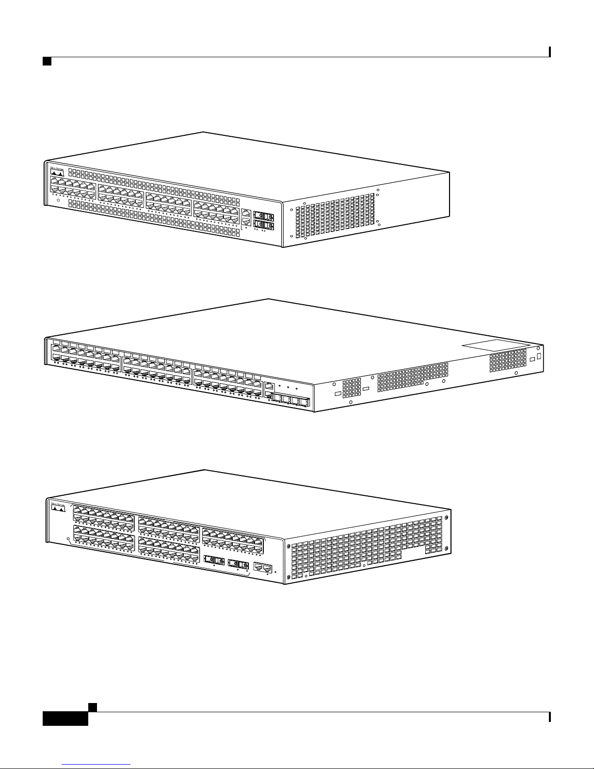
Switch Description
The Catalyst 2948G, 294 8G-GE- TX, and 29 80G switc hes are desig ned for
high-performa nce , hi g h-d ensity w iri ng -clo set ap pli cati ons. Figu re 1-1 through
Figure 1-3 show the switches.
Catalyst 2984G, 2948G-GE-TX, and 2980G Switch Hardware Installation Guide
78-6286-05
1-1
Page 30
Switch Description
Figure 1-1 Catalyst 2948G Switch
STATUS
Catalyst 2948G
C
O
N
S
O
10
B
a
se
Figure 1-2 Catalyst 2948G-GE-TX Switch
Chapter 1 Product Overview
L
E
1
0
0
0
B
as
e
-
X
T
98431
Figure 1-3 Catalyst 2980G Switch
1
2
1
2
3
4
5
1
6
7
8
9
10
11
12
13
14
15
STATUS
2
1
0
/
1
0
0
/
1
0
0
0
E
T
H
E
R
E
N
E
T
1
2
3
4
5
6
7
8
16
9
1
0
1
1
1
2
1
3
1
4
1
5
1
6
SLOT 2
1
7
1
8
1
9
2
0
2
1
2
2
2
3
2
4
2
5
2
6
2
7
2
8
2
9
3
0
3
1
3
2
3
3
3
4
3
3
1
1
7
1
8
1
9
2
0
2
1
2
2
2
3
2
4
2
5
2
SLOT 3
6
2
7
2
8
5
3
2
2
9
3
0
3
1
3
2
The Catalyst 2948G, 294 8G-GE- TX, and 2980G switche s interface wi th
networking equipment using Ethernet (10BASE-T), Fast Ethernet (100BASE-T),
and Gigabit Etherne t (1000BASE-T) inte rfaces. Dep ending on t he model , the
switches also support Gigabit Interface Converters (GBICs) or small fo rm-factor
pluggable (SFP) modules.
98434
C
A
T
A
L
Y
S
T
2
4
9
7
3
6
3
7
3
8
3
9
4
0
4
1
4
2
4
3
4
4
4
5
3
3
3
4
P
W
R
86
4
8
4
6
4
7
4
8
C
O
N
S
O
L
E
1
0
M
B
M
G
T
R
E
S
E
T
50747
Catalyst 2984G, 2948G-GE-TX, and 2980G Switch Hardware Installation Guide
1-2
78-6286-05
Page 31

Chapter 1 Product Overview
The Catalyst 2948G swit ch has 48 auto sensing and au toconfigur ing
10/100BASE-T Fast Ethernet fixed ports. The Catalyst 2948G-GE-TX switch has
48 autosensing and autoc onfiguring 10/100/ 1000BASE-T ports . The
Catalyst 2980G switch has 80 autose nsing and au toconfiguring 10/ 100BASE-T
Fast Ethernet fixed ports.
GBIC Module Supp or t
The Catalyst 2948G and 29 80G switc hes each have two Gigabit Ethern et uplink
ports with modular Gigabit Interface Converters (GBICs).
A GBIC is a hot-swappable input/output device that plugs into a Gigabit Ethernet
port module and links the port module with a fiber-optic network. For a detailed
description of Gigabi t Ethern et ports , see the “GBIC Features” section on
page 4-2.
Switch Description
For a complete list of supported GBIC modules, see Table 4-1 on pag e 4-3.
Note The Catalyst 2948G -GE-TX switch does not suppo rt GBIC mod ules.
The Gigabit Etherne t ports can be configured wit h any combina tion of GBIC
types.
The Gigabit Ethernet ports on these modules are used primarily for backbone
interconnection o f othe r high- perf orm ance s witc hes a nd ro ut ers.
SFP Module Support
The Catalyst 2948G-GE-TX switch has four small form-factor pluggable (SFP)
module slots. The switch uses SFP modules to establish Gigabit connections. The
SFP module slots are located on the front of the switch.
An SFP module is a hot-swappable input/output device that plugs into an SFP
module slot, linking the por t module with a fiber-optic network.
For a list of SFP modules supported by the Catalyst 2948G-GE-TX switch, see
Tab le 4-4 on p age 4-12 .
Catalyst 2984G, 2948G-GE-TX, and 2980G Switch Hardware Installation Guide
78-6286-05
1-3
Page 32

Switch Description
Note Catalyst 2948G-GE- TX switch onl y supports 10 00 Mbps an d full-dupl ex modes
on SFP modules.
Except for the 1000BASE-T SFP module, all of the SFP modules are used to
establish fiber-optic co nne ctio ns. You use fiber-optic cables with Lucen t (L C)
connectors to connect to an SFP module. The SFP modules support 850 to 1550
nanometer nom ina l wave lengths. T he se fiel d-re pla cea ble mo dule s p rovid e the
uplink optical interfaces, laser send (TX) and laser receive (RX). For a detailed
description of Gigabit Ethern et ports se e the “Connecting To an SFP Module”
section on page 4-12.
Switch Features
Chapter 1 Product Overview
Table 1-1 describes the Catalyst 2948G , 2948G-G E-TX, and 2980G swit ch
features.
Table 1-1 Catalyst 2948G, 2948G-GE-TX, and 2980G Switch Features
Feature Description
Ethernet s peeds
• Ethernet ( 10 BASE-T) int e rface to work stati ons and re peat ers
• Fast Ethernet (100BASE-T) interface to workstations, servers,
switches, and rout ers
Note Autonegotiation of li nk spe ed on ea ch 1 0/100 a nd 10/1 00/1 000
port allows migration to 100BASE-T or 1000BASE-T from a
10BASE-T or 100BASE-T installed base.
• Gigabit Eth erne t (1 000 BASE-T) copp er a nd Gi gab it Et hern et
(1000BASE-X) fiber-optic inte rface for ba ck bon e int erc on nect ion o f
high-perform ance switches a nd router s
Standard management and
support
• Layer 2 forw ardin g with an agg re gat e for war ding rate o f gr eater than
17.8 million packets per second
• 16,000 MAC addresses per system
Catalyst 2984G, 2948G-GE-TX, and 2980G Switch Hardware Installation Guide
1-4
78-6286-05
Page 33

Chapter 1 Product Overview
Table 1-1 Catalyst 2948G, 2948G-GE-TX, and 2980G Switch Features (continued)
Feature Description
Switch Description
Standard management and
support (conti nued)
Software m an agem en t
• Up to 1,024 VLANs wi th IEEE 802.1Q VLAN tagging on al l ports
and support f or VTP
• Port aggregation using PAgP
1
2
for 100-Mbps and 1-Gbps
EtherChannel
• CLI
3
and SNMP interfaces consi stent with the Catalyst 4500 series
and 6500 fam ily sw it ches
• Development of new features compatible with the Catalyst 6500
family switches
• Out-of-band mana geme nt thro ugh th e R J-45 10 BASE-T consol e
serial port
• 10BASE-T out-of-band management and in-band management
through any switch port with SNMP, Telnet client, and TFTP
Note The Catalyst 2948 G-G E-TX and 29 80G- A sw itches have a
10/100BASE-T management por t.
• RMON
• Standard Layer 2 elements:
4
with RMON 1
78-6286-05
–
802.1D Spanni ng Tree
–
–
–
Catalyst 2984G, 2948G-GE-TX, and 2980G Switch Hardware Installation Guide
5
CDP
VTP6 version 2 with pruni n g extensi ons
CGMP7 client
1-5
Page 34

Chapter 1 Product Overview
Switch Description
Table 1-1 Catalyst 2948G, 2948G-GE-TX, and 2980G Switch Features (continued)
Feature Description
Embedded ma nage ment
• Full SNMP implementation, including entity-MIB, all relevant
standard MIBs, a nd all r elevant Cisco M IBs
• The first four RMON g roups (Ethern et statistic s, Alarms, E v ents, and
History) supported on a per port basis witho ut an optional RM ON
processing module
• Redirection of tra ffic from any por t t o a “sn i ff” port. (Any sw itch ing
port can be desig nated as a “sniff” port.)
• Performance mana gement informat ion
Power supplies
• 120 W AC internal power supply on the Catalyst 2948G switch
• 156 W AC internal power supply on the Catalyst 2948G-GE-TX
switch
• 175 W AC internal power supply on the Catalyst 2980G switch
1. VTP = VLAN Trunking Protocol
2. PAgP = Port Aggregation Protocol
3. CLI = command-line interface
4. RMON = Remote Monitoring
5. CDP = Cisco Discovery Protocol
6. VTP = Virtual Terminal Protocol
7. CGMP = Cisco Group Management Protocol
Port Locations
This section de sc ribes th e por t loc atio ns an d nu mb er ing on the swi tche s.
10/100 and 10/100/1000 Ports
The 10/100 an d 10 /100/ 1 000 por ts a re c onfigure d in vertic al pa irs. Ea ch vert ical
pair has two Link Status LEDs below it. The LED on the left is for th e top port ;
the LED on the right is for the bottom port. For example, LED 1 is for the upper
port (port 1) a nd LED 2 is f or the b ottom por t ( por t 2) .
Catalyst 2984G, 2948G-GE-TX, and 2980G Switch Hardware Installation Guide
1-6
78-6286-05
Page 35

Chapter 1 Product Overview
Catalyst 2948G and 2980G Switch Ports
The Catalyst 2948G switch 10/100BASE-T ports are configured in two rows. The
top row contains odd-numbered ports (1 through 47), and the bottom row contains
even-numbered ports (2 t hr ough 48) .
The Catalyst 2980G switch 10/100BASE-T ports are configured in four rows. The
top two rows are num bere d 1 thr oug h 4 8, w ith the first row odd-nu mb ered (1
through 47) an d the secon d r ow even-numbered ( 2 th rou gh 48) . Th e bot tom two
rows are numbered 1 through 32, with the first row odd-numbered (1 through 31)
and the second row even-numbered (2 throu gh 32).
Two GBI C por ts a re a t t he r ight of t he fr ont pa nel on t he C ata lyst 2948G an d
Catalyst 2980G switches:
• On the Catalyst 2948G switches, these ports are located at the far rig ht of the
front panel. T he up per G iga bit Eth er net por t is p ort 49; t h e lower i s po rt 5 0.
The Link Sta tus L EDs fo r th ese p ort s a re below port 50.
Switch Components
• On the Catalyst 2980 G sw it ches, the GBI C Ethe rn et por ts a re l oca ted
immediately to the right of ports 31 and 32. The p ort on the left is port 33; the
port on the right is port 34. T he Link Sta tus LED s for the Gi gabit Ethe rnet
ports are located below each port.
Catalyst 2948G-GE-TX Switch Ports
The Catalyst 2948G -GE-TX 10/100/10 00BASE-T Gigabi t Etherne t ports are
configured in two rows. The top row contains odd-numbered ports (1 through 47),
and the bottom row contains even-numbere d ports (2 thr ough 48).
The SFP module slots are numbered left to right 49 throug h 52.
Switch Components
This section describe s the following Cataly st 2948G and 2980G switch
components:
• Management Ports, page 8
• Front Panel LEDs, page 8
Catalyst 2984G, 2948G-GE-TX, and 2980G Switch Hardware Installation Guide
78-6286-05
1-7
Page 36

Switch Components
• Airflow, page 9
• Power Supplies, page 11
Management Ports
The Catalyst 2948G, 2948G -GE-TX , and 2980G swit ches have two kinds of
management ports: co nsole seria l and Ether net. The Cat alyst 2948 G switches
have a 10BASE-T management port. The Catalyst 2948G-G E-TX an d 2980 G-A
switches have a 10/100BASE-T management port.
Tab le 1-2 on p age 1-9 lists the management options for the switches.
Console Serial Port
Chapter 1 Product Overview
An RJ-45 console serial port allows you to perform switch-management functions
using a terminal. See Table A-1 on page A-1 for the consol e connec tor pinou ts.
10BASE-T and 10/100BASE-T Ports
An RJ-45 10BASE-T port al lows you to pe rfor m TCP/I P sw itch- mana geme nt
functions (Telnet, SNMP, FTP), configure IP addre sses with BOOTP, and
download software images.
Note The Catalyst 2948G -GE-TX an d 2980 G-A swit ches have a 10/100BASE-T
management port.
This port is for network management only; it is not for switc hing. Connecti vity is
not available between this port and th e 10/100BASE-T swit ching por ts.
Front Panel LEDs
The LEDs on the front panels of the Catalyst 2948G, 2948G-GE-TX, and 2980G
switches perform the following functions:
• STATUS LEDs indicate the operating state of the switches.
• Link Status LEDs provide m an agemen t a nd i ndic ate sw itch ing port sta tus.
Catalyst 2984G, 2948G-GE-TX, and 2980G Switch Hardware Installation Guide
1-8
78-6286-05
Page 37

Chapter 1 Product Overview
Switch Components
• PSI LED indicates the inter nal power supply status on the Catalyst 2948G
switch.
• PWR LED indicat es the i nte rnal power suppl y status on the C atal yst 2980G
switch.
• RPS LED provides the external redundan t power supply status.
Table 1-2 describes the LEDs.
Table 1-2 Front Panel LEDs
LED Color/Statue Description
STATUS Indicates the results of a series of self-test diagnostics.
Green
Red
Amber
Off
All tests pass.
A test other than an individual port test fails.
System boot or di ag nostic te sts in pr ogress.
Switch is disabl ed .
Link Status Indicates the li nk status of a port .
Green
Amber
Flashing
Off
Port is operati onal .
Port is disabl ed by us er.
Power-on self-test indicates faulty port.
No signal detected, or link configuration failure.
PSI, PWR, and RPS Indicates power supply operat ion or failure .
Green
Amber
Power supply is operational.
Power supply has failed or is in Standby mode.
Airflow
Note For environmental specifications, see Chapter 2, “Site Planning.”
On the Catalyst 2948G and 298 0G switches , the system fan asse mbly provides
cooling air for the internal chassis components. The fans exhaust warm air from
one end and draw in c ool ai r a t t he oth er end .
Catalyst 2984G, 2948G-GE-TX, and 2980G Switch Hardware Installation Guide
78-6286-05
1-9
Page 38

Switch Components
If an individual fan fails, the other fans co ntinue to ru n. Sensor s m onitor the
internal air tem peratures. If the air te mp er atu r e exceeds a tolerable threshold , th e
environmental monitor displays warning messages.
On the Catalyst 2 948G-GE-TX, a blower system draws cool air in from the front
and sides of the switch and exhausts ai r out the bac k.
Figure 1-4 shows the direction of airflow through the Catalyst 2 948G switch.
Figure 1-5 shows the direction of airflow through the Catalyst 2948G-GE-TX
switch.
Figure 1-6 shows the direction of airflow through the Catalyst 2 980G switch.
Figure 1-4 Catalyst 2948G Airflow
Chapter 1 Product Overview
STATUS
Catalyst 2948G
C
O
N
S
O
L
E
1
0
B
a
s
e
T
Figure 1-5 Catalyst 2948G-GE-TX Airflow
1
0
0
0
B
a
s
e
- X
98432
98720
Catalyst 2984G, 2948G-GE-TX, and 2980G Switch Hardware Installation Guide
1-10
78-6286-05
Page 39

Chapter 1 Product Overview
Figure 1-6 Catalyst 2980G Airflow
1
2
1
2
3
4
5
1
6
7
8
9
10
11
12
13
14
15
STATUS
2
1
0
/
1
0
0
/
1
0
0
0
E
T
H
E
R
E
N
E
T
1
2
3
4
5
6
7
8
16
9
1
0
1
1
1
2
1
3
1
4
1
5
1
6
SLOT 2
1
7
1
8
1
9
2
0
2
1
2
2
2
3
2
4
2
5
2
6
2
7
2
8
2
9
3
0
3
1
3
2
1
7
1
8
1
9
2
0
2
1
2
2
2
3
2
4
2
5
2
SLOT 3
6
2
7
2
8
2
9
3
0
3
1
3
2
Power Supplies
There is no power switch on the switches. AC power is present in the power
supply when t he power c ord is pl ugged i n.
Switch Components
C
A
T
A
L
Y
S
T 2
4
9
7
8
3
3
3
4
3
3
1
5
3
6
3
7
3
8
3
9
4
0
4
1
4
2
4
3
4
4
4
5
3
2
3
3
4
3
4
P
W
R
6
4
8
6
4
7
4
8
C
O
N
S
O
L
E
1
0
M
B
M
G
T
R
E
S
E
T
32064
The environmental monitoring and reporting functions allow you to maintain
normal system op erat ion by c orr ect ing ad verse e nvironmenta l c ondi tion s b ef ore
loss of operation.
Each po wer suppl y monitor s its o wn tempe rature an d output volta ges. If th e power
supply becomes excessively hot, it shut s down to prevent damage. The swi tches
monitor the op er ati ng cond ition o f th e power supp ly and re po rt the status usin g
switch software.
The switches have the following power supplies:
• 120 W AC internal power supply—C ata lyst 2 948 G sw itch
• 156 W AC internal power supply—C ata lyst 2948 G- GE-T X swi tch
• 175 W AC internal power supply—C ata lyst 2 980 G sw itch
• 156 W AC internal power supply—C ata lyst 2 980 G-A swit ch
Note For complete power specifications for th e Catalyst 294 8G, 2948G -GE-TX ,
and 2980G switches, se e A pp end ix A, “S peci ficat ions. ”
These switches also be used with an o ptional Cisco Re dundant Power System
(RPS).
Catalyst 2984G, 2948G-GE-TX, and 2980G Switch Hardware Installation Guide
78-6286-05
1-11
Page 40

Switch Components
Chapter 1 Product Overview
• The Catalyst 2948G switch uses the Ci sco RPS 600 AC power supply
(PWR600-AC-RPS-CAB).
The Cisco R PS 60 0 s uppo rts fou r exte rnal d evices tha t u se up to 1 50 W DC
each. Use a one-to-one cable (one connector at each cable end) to connect
four external devices to the f our DC outpu t power mo dule s.
The power source is pa rti ally re du ndant . T he re a re t wo AC input power
modules for the Cisco RPS and one DC output power mod ule for each
external de vice. The A C input to the Cisco RPS is fully redundant, but the DC
output to the ex ternal devices is not.
Warning
Warning
Attach only the Cisco RPS (model PWR600-AC-RPS) to the RPS receptacle.
Statement 112
• The Catalyst 2948G-G E-TX sw itch uses the Ci sco RPS 675 (model
PWR675-AC-RPS-N1).
The RPS 675 supports six extern al netwo rk devices and provides D C power
to one failed de vice at a time. It automatically senses when the internal power
supply of a connected device fail s and provides power to that device, whic h
prevents loss of network traffic.
Attach only the Cisco RPS (model PWR675-AC-RPS-N1=) to the RPS receptacle.
Statement 100C
• The Catalyst 2980G -A switch uses the Cisco RPS 300
(PWR300-AC-RPS-N1).
The RPS 300 supports six extern al network devices an d provides power to
one failed device at a time. I t a utom atic ally se nse s wh en th e power supply of
a connected device fails and provides the necessary power to the failed device
to prevent loss of network traffic. When the internal power supply of the
device has been brought up or replaced , the RPS automa tically stop s
powering the device.
Warning
Catalyst 2984G, 2948G-GE-TX, and 2980G Switch Hardware Installation Guide
Attach only the Cisco RPS (model PWR300-AC-RPS-N1) to the RPS receptacle.
Statement 100B
1-12
78-6286-05
Page 41

Chapter 1 Product Overview
A Cisco RPS can only power one switch at a time. If more than one switch fails
at the same time, any subsequent switch is not su pported by the RPS u ntil the f irst
switch failure is resolved. For more information, refer to the documentation that
was included with your RPS.
On the Catalyst 2948G swi tch, you must use a Y cable to connec t the switc h to
two RPS 600 power supplies. Each RPS 600 has status LEDs (PSI and RPS).
On the Catalyst 2980G-A switch, eac h RPS 300 power supply has an individual
power cord and has status LEDs (PSI, PWR, and RPS).
The RPS uses redundant power supplies. If one of the power suppli es in the RPS
fails, the RPS will automatically switch over to the other power supply without
forcing the switch t o reboot.
Note On the Catalyst 2948G -GE-TX an d 2948G swi tches, only one power source can
supply power to the switch a t a ny one time . W hen you ar e u sing a n RPS, unplu g
the local power cord for the switch. If you are using the local power supply, the
RPS can be connected but must not be powered on. The switches can be powered
by both the internal power supply and the RPS at the sa me time.
Switch Components
Catalyst 2984G, 2948G-GE-TX, and 2980G Switch Hardware Installation Guide
78-6286-05
1-13
Page 42

Switch Components
Chapter 1 Product Overview
Catalyst 2984G, 2948G-GE-TX, and 2980G Switch Hardware Installation Guide
1-14
78-6286-05
Page 43

Warning
Warning
CHAPTER
2
Site Planning
Before you install, operate, or service the sy stem, read the Site Preparation and
Safety Guide. This guide contains important safety information you should know
before working with the system.
Only trained and qualified personnel should be allowed to install, replace, or
service this equipment.
Statement 1030
Statement 200
78-6286-05
This chapter describes ho w to prepar e your site f or the insta llation of y our switch
and contains t hese se ction s:
• Site Power Requirements a nd H eat D issipa tion, p age 2
• System Ground Connection Guidelines (Catalyst 2948G and 2980G Switches
Only), page 3
• Site-Planning Check list, pa ge 7
Note See the “Site-Planning Checklist” section on page 7 to help ensure that you
complete all site-planning activities before you install the switch.
Catalyst 2984G, 2948G-GE-TX, and 2980G Switch Hardware Installation Guide
2-1
Page 44

Chapter2 Site Planning
Site Power Requirements and H eat Dissipation
Site Power Requirements and Heat Dissipation
Note Catalyst 2948G, 294 8G-G E-TX , a nd 2980G s witc hes have in ter nal power
supplies. All of t he switc hes su ppo rt Cisc o Re dun dant Power System ( RPS) fo r
redundant ope ratio n.
This section provides site po wer requirement s and heat dissipation specif icati ons
for the Catal yst 2948G , 2948 G -GE- TX, a nd 2980G swi tches . You should verify
site power before you install a switch.
Power requirements can vary for each Catalyst switch. Knowing the power
requirements can be use ful for pl an ning the power dis tribution syst em ne ede d to
support the switches. Heat specifications are used for determining the
air-conditioning requirements for an installation.
Note Refer to the Site Preparation and Safe ty Gui de for site power requireme nts,
preinstallati on requ ireme nts, an d EMI reco mmen datio ns.
Table 2-1 descr ibes the po wer r equireme nts and he at dissip ation sp ecific ations f or
the Catalyst 2948G, 29 48G-G E-T X, a nd 2980G switc hes.
Table 2-1 Power Requirements and Heat Dissipation Specifications
Power
Model Number/
Module Type
Supply
Output
(Watts)
AC Input
Power
(Watts)
Heat Diss
(BTU/Hr) AC Input Current (Amps)
Catalyst 2948G switch 120 200 645 90 VAC: 2.0
120 VAC: 1.6
180 VAC: 1.0
240 VAC: 0.9
Catalyst 2948G-GE-TX swit ch 156 130 445 100 VAC: 1.5
240 VAC: 0.8
Catalyst 2984G, 2948G-GE-TX, and 2980G Switch Hardware Installation Guide
2-2
78-6286-05
Page 45

Chapter 2 Site Planning
System Ground Connection Guidelines (Catalyst 2948G and 2980G Switches Only)
Table 2-1 Power Requirements and Heat Dissipation Specifications (continued)
Power
Supply
Model Number/
Module Type
Catalyst 2980G switch 175 300 950 90 VAC: 3.0
Catalyst 2980G-A switch 156 208 670 90 VAC: 2.3
Output
(Watts)
AC Input
Power
(Watts)
Heat Diss
(BTU/Hr) AC Input Current (Amps)
120 VAC: 2.4
180 VAC: 1.6
240 VAC: 1.0
120 VAC: 1.7
180 VAC: 1.1
240 VAC: 0.9
System Ground Connection Guidelines
(Catalyst 2948G and 2980G Switches Only)
Two system (earth) grounding holes are provided in an enclosure near the power
supplies.
Note These guidelines do not apply to the Ca talyst 294 8G-GE -TX switche s.
See Figure 2-1 for the locatio n of th e gro undin g h ole s on the C atal yst 2948G
switches and Figure 2-2 for the location on the Catalyst 2980G switches.
Catalyst 2984G, 2948G-GE-TX, and 2980G Switch Hardware Installation Guide
78-6286-05
2-3
Page 46

System Ground Con nection Guidelines (Catalyst 2948G and 2980 G Switches Only)
Figure 2-1 Grounding Holes on the Catalyst 2948G Switch
M4 screw holes (2)
Figure 2-2 Grounding Holes on the Catalyst 2980G Switch
Chapter2 Site Planning
33110
M4 screw holes (2)
To m a ke an ad eq ua te g ro undin g c on nect ion , y ou nee d t hes e c om pon en ts a nd
tools:
• Grounding lug— The gro und ing lu g m ust have two M4 sc rew hol es. See
Figure 2-1 for the location of the M4 screw holes on the Catalyst 2948G
switch and Figure 2-2 for the Catalyst 2980G switch.
The grounding lugs ar e not available from Cisco Systems; any
electrical -connec tor vendor can provide this lug.
• Two M4 (metric) hex-head screws with locking washers—These screws are
not available from Cisco Systems; they are available from any commercial
hardware vendor.
• One grounding wi re ( 6 AWG recommended)—The leng th o f the gr oundi ng
wires depends on the location of your switch within the site and its proximity
to proper grounding facil ities. The grounding wire is not a vailable from Cisc o
Systems; it is available from any commercial cable vendor.
33109
Catalyst 2984G, 2948G-GE-TX, and 2980G Switch Hardware Installation Guide
2-4
78-6286-05
Page 47

Chapter 2 Site Planning
System Ground Connection Guidelines (Catalyst 2948G and 2980G Switches Only)
• Number 2 Phillips head screwdriver.
• Crimping tool—Thi s must be large enoug h to accommo date th e girth of the
grounding lug when you crimp the grounding c able into the lug.
• Wire-stripping tool.
Connecting the Switch to Earth Ground
This proced ure descr ibes how to connect th e Catalyst 294 8G, 2948G -GE-TX ,
and 2980G switches to e arth gro und. We strongly recommend th at yo u com ple te
this procedure be for e c onnec ti ng system p ower o r tu rnin g o n y our sw it ch.
T o attach the grounding lug and cable to the grounding pad on the Catalyst 2948G,
2948G-GE-TX, and 2980G switche s, follow these steps :
Step 1 Use a wire -stripp ing tool to remove approxi mate ly 0.75 inc hes (19 mm ) of the
covering from the end of the groun ding wire.
Step 2 Insert the stripped end of the ground ing wir e into the ope n end of the gr ounding
lug.
Step 3 Use th e crimping t ool to secure the grounding wire in place in the grounding lug.
Step 4 Locate the grounding pad on the switch .
See Figure 2-3 for the location of the grounding pad on the Catalyst 2948G switch
and Figure 2-4 for the Catalyst 2980G switch.
Catalyst 2984G, 2948G-GE-TX, and 2980G Switch Hardware Installation Guide
78-6286-05
2-5
Page 48

System Ground Con nection Guidelines (Catalyst 2948G and 2980 G Switches Only)
Figure 2-3 Connecting System Ground on the Catalyst 2948G Switch
Wire
Grounding
Screws
Grounding lug
pad
Chapter2 Site Planning
33112
Figure 2-4 Connecting System Ground on the Catalyst 2980G Switch
33111
Wire
Grounding
pad
Step 5
Screws
Grounding lug
Remove the label th at c overs the gr oundi ng pad.
Step 6 Place the grounding lug against the grounding pad on the rear panel of the switch.
Step 7 Install locking washers; tighten them to secure the grounding lug to the grounding
pad.
Step 8 Insert t wo scr ews throu gh the hole s in t he g rou nding lug a nd the gr oundi ng pad.
Ensure that the grounding lug and the attached wire will not interfere with other
switch hardware or ra ck equ ipment .
Catalyst 2984G, 2948G-GE-TX, and 2980G Switch Hardware Installation Guide
2-6
78-6286-05
Page 49

Chapter 2 Site Planning
Site-Planning Checklist
Step 9 Prepare the other en d of the ground ing wir e and conne ct it to an a ppropriat e
grounding point at you r site to ensure a dequat e earth groun d for the swit ch.
Site-Planning Checklist
Table 2-2 lists the site-planning activ ities that you should complete before you
install the Catalyst 2948G, 2948G-GE-TX, and 2980G switches. Completing
each activity helps ensure a successful switch installation.
Table 2-2 Site-Planning Checklist
Task No. Planning Activity Verified By Time Date
1 Space evaluation:
Space and lay out
Floor covering
Impact and vibr ation
Lighting
Maintenance access
2 Environmental evaluation:
Ambient temperature
Humidity
Altitude
Atmospheric contamination
Airflow
3 Power evaluation:
Input power type
Proximity of r ece ptac le to the e quipm en t
Dedicated (se pa rate) c irc uit s fo r re dun dant p ower suppli es
UPS for power failures
4 Groundi ng evaluation:
Circuit breaker size
Catalyst 2984G, 2948G-GE-TX, and 2980G Switch Hardware Installation Guide
78-6286-05
2-7
Page 50

Chapter2 Site Planning
Site-Planning Checklist
Table 2-2 Site-Planning Checklist (continued)
Task No. Planning Activity Verified By Time Date
5 Cable and interface equipment evaluation:
Cable type
Connector type
Cable distance limitations
Interface equipment (transceivers)
6EMI evaluation:
Distance limitations for signaling
Site wiring
RFI levels
Catalyst 2984G, 2948G-GE-TX, and 2980G Switch Hardware Installation Guide
2-8
78-6286-05
Page 51

Warning
Warning
CHAPTER
3
Installing the Switch
Before you install, operate, or service the sy stem, read the Site Preparation and
Safety Guide. This guide contains important safety information you should know
before working with the system.
Only trained and qualified personnel should be allowed to install, replace, or
service this equipment.
Statement 1030
Statement 200
78-6286-05
This chapter d escri bes how to insta ll the Ca ta lyst 2948G, 2948G -GE -TX ,
and 2980G switches. For first-t ime installations, perform the procedures in these
sections in the order listed:
• Preparing for Installation, page 2
• Installing the Catalyst 294 8G and 2980G Swit ches, page 6
• Installing the Catalyst 294 8G-GE -TX Switch, page 9
• Connecting Power to the Switches, page 19
• Connecting a Terminal to the Console Serial and Ethernet Management Ports,
page 22
Note Before starting the installation procedures in this chapter, complete the
site-planning checklist in Chapter 2, “Site Planning.”
Catalyst 2984G, 2948G-GE-TX, and 2980G Switch Hardware Installation Guide
3-1
Page 52

Preparing for Inst al la tion
Preparing for Installation
This section provides informa tion ab out these to pics :
• EMC Regulatory Statements, page 2
• Checking the Shipping Contai ner, page 4
EMC Regulatory Statements
This section includes specific regulatory statements about the switches.
U.S.A.
U.S. regulatory information for this product is in the front matter of this manual.
Chapter 3 Installing the Switch
Taiwan
Warning
This is a Class A Information Product, when used in residential environment,
it may cause radio frequency interference, under such circumstances, the
user may be requested to take appropriate countermeasures.
Catalyst 2984G, 2948G-GE-TX, and 2980G Switch Hardware Installation Guide
3-2
78-6286-05
Page 53

Chapter 3 Installing the Switch
VCCI Class A Notice for Japan
Preparing for Installation
Korea
Warning
Warning
This is a Class A product based on the standard of the Voluntary Control
Council for Interference by Information Technology Equipment (VCCI). If this
equipment is used in a domestic environment, radio disturbance may arise.
When such trouble occurs, the user may be required to take corrective
actions.
This is a Class A Device and is registered for EMC requirements for industrial
use. The seller or buyer should be aware of this. If this type was sold or
purchased by mistake, it should be replaced with a residential-use type.
Catalyst 2984G, 2948G-GE-TX, and 2980G Switch Hardware Installation Guide
78-6286-05
3-3
Page 54

Preparing for Inst al la tion
Class A Notice for Hungary
Chapter 3 Installing the Switch
Warning
This equipment is a class A product and should be used and installed properly
according to the Hungarian EMC Class A requirements (MSZEN55022). Class A
equipment is designed for typical commercial establishments for which
special conditions of installation and protection distance are used.
Checking the Shipping Container
Do not disca rd t he p ac king c art on an d othe r pack in g m ateri al s aft er you un pack
the switch. Flatten the packing carton and store it. You will need the packing
materials if you need to move or ship the switch in the future. Repacking
instructions are provided in Appendix B, “Rep ackin g a Switch.”
Check the contents of the accessory kit against the accessories checklist and the
packing slip. Verify that you received all listed equipment.
Catalyst 2948G and 2980G Switches
The Catalyst 2948G and 29 80G switche s are shipped wit h these item s:
• This hardware guide
• AC power cord
• RJ-45 to DB-9 cable
• DB-9 to RJ-45 c ab le
Catalyst 2984G, 2948G-GE-TX, and 2980G Switch Hardware Installation Guide
3-4
78-6286-05
Page 55

Chapter 3 Installing the Switch
• ESD wrist strap
• Mounting kit
Catalyst 2948G-GE-TX Switches
The Catal yst 2 948 G-G E-TX swit ch is shi pped wit h th ese it ems :
• This hardware guid e
• About the Catalyst 2948 G Docum entati on flyer
• AC power cord
• One RJ-45-to-DB-9 ada pter cabl e (78-338 3-XX)
• Mounting kit containing:
–
Four rubber feet for mount ing the swi tch on a table (5 1-0089 )
Preparing for Installation
–
Two 19 -in ch ra ck-m ou nti ng bra ckets ( 700- 08 209-X X)
–
Four Phillips machine screws for attaching the brackets to a rack
(48-0655-XX)
–
One cable guide (700-0 5613-XX )
–
One black Phillips machine scre w for atta ching the ca ble guide to one of
the mounting b racket s (48-06 54- XX)
–
One Redundant Power System (RPS) connector cover for wall mounting
(700-16465-XX)
–
Two Phillips pan-head screws for attachin g the RPS cov er (48 -0482-XX)
–
Four Phillips truss-head screws for attaching wall-mounting bra ckets
(48-0656-XX)
–
Four Phillips pan-head screws for attaching the switch to a rack
(48-0523-XX)
Catalyst 2984G, 2948G-GE-TX, and 2980G Switch Hardware Installation Guide
78-6286-05
3-5
Page 56

Chapter 3 Installing the Switch
Installing the Catalyst 2948G and 2980G Switches
Installing the Catalyst 2948G and 2980G Swit ches
Warning
To prevent bodily injury when mounting or servicing this unit in a rack, you
must take special precautions to ensure that the sys tem remains stable. The
following guidelines are provided to ensure your safety:
• This unit should be mounted at the bottom of the rack if it is the only unit i n the rack.
• When mounting this unit in a partially filled rack, load the rack from the bottom to the
top with the heaviest component at the bottom of the rack.
• If the rack is provided with stabilizing devices, install the stabilizers before mounting
or servicing the unit in the rack.
A standard rac k-m ount k it is in clude d for moun t ing th e sw itch in a
standard 19-inch (48.3 cm) eq uipmen t rack with two unobst ructed ou ter posts.
This kit is not suitable for racks with obstructions (such as a power strip) that
could impair access to the switch.
Required Installat i on To ols
Statement 1006
You will need the following too ls an d equip ment to install the switc h chassis in a
rack:
• Rack-mount kit
• Tape measure and level
• Number 1 Phillips, number 2 Phillips, or a 3/16-inch flat-blade screwdriver
• Antistatic mat or antistatic foam
• Your own electrost atic d isch arge (E SD) gr ou nding stra p or t he d isp osable
ESD strap included with the switch
Note For more information about ESD, refer to the Site Preparation and Safety Guide.
Catalyst 2984G, 2948G-GE-TX, and 2980G Switch Hardware Installation Guide
3-6
78-6286-05
Page 57

Chapter 3 Installing the Switch
Installing the Catalyst 2948G and 2980G Switches
Rack-Mounting the Catalyst 2948G and 2980G Switches
To install Catalyst 2940G and 2980G switches in a 19-inch rack, follow these
steps:
Step 1 Prepare for installation as follows:
a. Place the chassis on the floor or on a sturdy table, as close as possible to the
rack. Leave enough clearance to allow yourself to move around the chassis.
b. Use the tape measure to measure the depth of the rack. Measure from the
outside of the front-m ounting posts to the outside of the rear-mounting strip.
The depth must be at least 19.25 inche s (48.9 cm) an d not great er than
32 inches (81.3 cm).
c. Measure th e sp ace be twee n the in ner edge s of the lef t fr ont- an d r ight front -
mounting posts to ensure that it is 17.75 inches (45.09 cm) wide. (The chassis
is 17.5 inches [44 cm] wide and mus t fit between th e mounti ng posts. See
Figure 3-2.)
d. Open the rack-mou nt k it a nd refer to the c om p onen t checklist in Table 3-1 to
verify that all parts ar e inclu ded.
Table 3-1 Rack-Mount Kit Checklist
Part Description Quantity
L brackets 2
M4 Phillips pan-head screws 4
12-24 x 3/4-inch Phillips binder-head screws 6
Note Some equipment racks have a power strip along the length of one of the rear posts.
If the rack has this feature, consider the position of the strip when planning
fastener po ints. Before i nstalling th e L brackets o n the chassi s, determine wh ether
to install the chassis from the front or the rear of the rack.
Step 2 Attach the left and right L brackets using the four M4 Phillips pan-head screws
provided in the rack-mount kit (see Figure 3-1).
Catalyst 2984G, 2948G-GE-TX, and 2980G Switch Hardware Installation Guide
78-6286-05
3-7
Page 58

Installing the Catalyst 2948G and 2980G Switches
The L brackets conne ct th e switc h ch assis to the ra ck. You can mount the
L brackets to the front- or rear-mounting holes of the chassis, depending on which
end is in the front of th e rack.
Note The Catalyst 2948G switch is shown in the rack-mounting illustrations.
The rack-mounti ng proce dure for the Catal yst 2980G switc h is t he sa me.
Figure 3-1 Attaching the L Brackets
STATUS
Catalyst 2948G
Chapter 3 Installing the Switch
C
O
N
S
O
L
E
1
0
0
0
B
a
s
e
- X
1
0
B
a
s
e
T
98435
Step 3
Figure 3-2 shows how to attach the front of the switch to the rack. You can also
attach the rear of the switch to the rack, depending on the configuration of your
rack.
Install the chassis in the rack as follows:
a. Position the switch chassis in the rack (see Figure 3-2):
• If the chassis front panel is to be in the front of the rack, insert the rear
of the chassis between the mounting posts.
• If the rear of the chassis is to be in th e front of the rack, insert the front
of the chassis between the mounting posts.
b. Align the mounting holes in the L bracket with the mounting holes in the
equipment rac k.
c. Secure the chassis using six 12-24 x 3/4-inch screws (three per side) through
the elongated holes in the L bracket and i nto the th reade d holes in the
mounting post.
d. Use the tape measure and level to ensure that the chassis is installed straight
and level.
Catalyst 2984G, 2948G-GE-TX, and 2980G Switch Hardware Installation Guide
3-8
78-6286-05
Page 59

Chapter 3 Installing the Switch
17.75 inches (45.09 cm)
Figure 3-2 Installing the Switch in the Rack
17.75 inches (45.09 cm)
17.75 inches (45.09 cm)
STATUS
Catalyst 2948G
C
1
Installing the Catalyst 2948G-GE-TX Switch
O
N
S
O
L
E
1
0
0
0
B
a
s
e
- X
0
B
a
s
e
T
98436
Installing the Catalyst 2948G-GE-TX Switch
Warning
To prevent bodily injury when mounting or servicing this unit in a rack, you
must take special precautions to ensure that the sys tem remains stable. The
following guidelines are provided to ensure your safety:
• This unit should be mounted at the bottom of the rack if it is the only unit i n the rack.
• When mounting this unit in a partially filled rack, load the rack from the bottom to the
top with the heaviest component at the bottom of the rack.
• If the rack is provided with stabilizing devices, install the stabilizers before mounting
or servicing the unit in the rack.
Statement 1006
Catalyst 2984G, 2948G-GE-TX, and 2980G Switch Hardware Installation Guide
78-6286-05
3-9
Page 60

Chapter 3 Installing the Switch
Installing the Cat al ys t 294 8G- GE - T X Switc h
To install a Catalyst 2948G-GE-TX switch, follow the steps described in these
procedures:
• Rack-Mounting th e Catalyst 2948 G-GE- TX Switch, pa ge 10
• Wall -Mount ing the Catal yst 2948G-G E-TX Swit ch, page 16
• Mounting the C atalyst 2948 G- GE-TX Swi tch o n a Table or Shelf, page 19
Rack-Mounting the Catalyst 2948G-GE-TX Switch
To install a Catalyst 2948G-GE-TX switch in a 19-inch rack (24-inch racks
require optional mou nting hardwar e), follow the instruc tions desc ribed in thes e
procedures:
• Removing Screws from the Swit ch, page 10
• Attaching Brackets to the Switch, page 11
• Mounting the Switch in a Rack, page 14
• Attaching the Cable Guide, page 15
• Attaching the Brackets to the Switch for Wall-Mounting, page 16
• Attaching the RPS Conne ctor Cover, page 17
• Mounting the Switch on a Wall, page 17
• Mounting the C atalyst 2948 G- GE-TX Swi tch o n a Table or Shelf, page 19
Note Installing the switch in a 24-inch rack requires an optional bracket kit not included
with the switch. Yo u can ord er a kit co ntain ing the 24- inch rack -mount ing
brackets and ha rd ware (o rde r part num be r R CKMN T-1RU=) from Cisco.
Removing Screws from the Switch
If you plan to install the switch in a rack, you must first remove screws in the
switch chassis so that mounting brackets can be attached. Figure 3-3 shows how
to remove the chassis screws from the switch.
Catalyst 2984G, 2948G-GE-TX, and 2980G Switch Hardware Installation Guide
3-10
78-6286-05
Page 61

Chapter 3 Installing the Switch
Installing the Catalyst 2948G-GE-TX Switch
Figure 3-3 Removing Screws from the Catalyst 2948G-GE-TX Switch
98659
Attaching Brackets to the Switch
The bracket orien tation a nd the brac kets you use depend on whethe r you are
attaching the brac kets for a 19 -inc h o r a 24- inc h ra ck. For 19-i nch r ack s, use the
brackets that are included in the mounting kit.
Note Installing the switch in a 24-inch rack requires an optional bracket kit not included
with the switch. Yo u can ord er a kit co ntain ing the 24- inch rack -mount ing
brackets and ha rd ware (o rde r part num be r R CKMN T-1RU=) from Cisco.
Figure 3-4 through Figure 3-9 show how to attac h each type of br acket to one si de
of the switch. Fo llow the same steps to attach the second bracket to the opposite
side of the switc h.
Catalyst 2984G, 2948G-GE-TX, and 2980G Switch Hardware Installation Guide
78-6286-05
3-11
Page 62

Installing the Cat al ys t 294 8G- GE - T X Switc h
Figure 3-4 Attaching Brackets for 19-Inch Racks, Front Panel Fo rward
1
1 Phillips flat-head screws
Chapter 3 Installing the Switch
98660
Figure 3-5 Attaching Brackets for 19-Inch Racks, Rear Pa nel Forward
98657
1
1 Phillips flat-head screws
Catalyst 2984G, 2948G-GE-TX, and 2980G Switch Hardware Installation Guide
3-12
78-6286-05
Page 63

Chapter 3 Installing the Switch
Figure 3-6 Attaching Brackets for 24-Inch Racks, Front Panel Forward
1 Phillips flat-head screws
Installing the Catalyst 2948G-GE-TX Switch
1
98661
Figure 3-7 Attaching Brackets for 24-Inch Racks, Rear Panel Forward
98662
1
1 Phillips flat-head screws
Catalyst 2984G, 2948G-GE-TX, and 2980G Switch Hardware Installation Guide
78-6286-05
3-13
Page 64

Installing the Cat al ys t 294 8G- GE - T X Switc h
Figure 3-8 Attaching Brackets for 19-Inch Telco Racks
1 Phillips flat-head screws
Figure 3-9 Attaching Brackets for 24-Inch Telco Racks
Chapter 3 Installing the Switch
1
98663
1 Phillips flat-head screws
Mounting the Switch in a Rack
After the brackets are attached to the switch, use the four supplied number-12
Phillips machine screws to securely attach the brackets to the rack, as shown in
Figure 3-10.
1
98664
Catalyst 2984G, 2948G-GE-TX, and 2980G Switch Hardware Installation Guide
3-14
78-6286-05
Page 65

Chapter 3 Installing the Switch
Figure 3-10 Mounting the Catalyst 2948G-GE-TX Switch In a Rack
1 Phillips machine screws
Attaching the Cable Guide
Installing the Catalyst 2948G-GE-TX Switch
98665
1
We recommend attaching the cable guid e to the left or right brack et to pr ev ent the
cables from obscuring the front panel of the switch and the other devices installed
in the rack. Use the supplied black screw, as shown in Figure 3-11, to attac h th e
cable guide to the left or right bracket.
Figure 3-11 Attaching the Cable Guide on the Catalyst 2948G-GE-TX Switch
1
1 Cable guide screw
98666
Note The Catalyst 2948G-GE-TX switch ships with a special cable guide, as shown in
Figure 3-11. This cable guide secures up to 48 cables. Use the supplied black
screw to mount it on the left or right bracket.
Catalyst 2984G, 2948G-GE-TX, and 2980G Switch Hardware Installation Guide
78-6286-05
3-15
Page 66

Chapter 3 Installing the Switch
Installing the Cat al ys t 294 8G- GE - T X Switc h
Wall-Mounting the Catalyst 2948G-GE-TX Switch
To install the Catalyst 2948G-GE-TX switch on a wall, follow the instructions in
these procedures:
• Attaching the Brackets to the Switch for Wall-Mounting, page 16
• Attaching the RPS Conne ctor Cover, page 17
• Mounting the Switch on a Wall, page 17
Attaching the Brackets to the Switch for Wall-Mounting
Figure 3-12 shows how to attach a 19-inch bracket to one si de of the sw itch.
Follow the same steps to attach the second bracket to the opposite side of the
switch.
Figure 3-12 Attaching the 19-Inch Brackets for Wall-Mounting
1
98667
1 Phillips truss-head screws
Catalyst 2984G, 2948G-GE-TX, and 2980G Switch Hardware Installation Guide
3-16
78-6286-05
Page 67

Chapter 3 Installing the Switch
Attaching the RPS Connector Cover
If you are not using a Cisco RPS with your switch, use the two Phillips pan-head
screws to attach the RPS connecto r cover to the back of the switch before you
mount it, as sh own in Figu re 3-13.
Installing the Catalyst 2948G-GE-TX Switch
Warning
If an RPS is not connected to the switch, install an RPS connector cover on the
back of the switch.
Statement 265
Figure 3-13 Attaching the RPS Connector Cover on the Catalyst 2948G-GE-TX
Switch
R
ATING
100-200V ~
1.6A-0>9A, 50-60 H
Z
DC IN
PU
PO
SPECIFIED
+12v @
TS FO
W
ER SUPPLY
IN M
R REM
ANUAL
8.5a
O
TE
98668
1 2
1 Phillips pan-head screws 3 RPS connector
2 RPS connector cover
Mounting the Switch on a Wall
For the best support of the swi tch and cabl es, ma ke sure the switc h is attach ed
securely to wall studs or to a firmly atta ched plywood mo unting ba ckboard .
Mount the swi tch wi th t he f ro nt p anel faci ng u p, as shown in Figur e 3-14.
Catalyst 2984G, 2948G-GE-TX, and 2980G Switch Hardware Installation Guide
78-6286-05
3
3-17
Page 68

Installing the Cat al ys t 294 8G- GE - T X Switc h
Chapter 3 Installing the Switch
Warning
To comply with safety regulations, mount the switches on a wall with the front
panel facing up.
Statement 266
Figure 3-14 Mounting the Switch on a Wall
1
1
1 User-supplied screws
Catalyst 2984G, 2948G-GE-TX, and 2980G Switch Hardware Installation Guide
3-18
98669
78-6286-05
Page 69

Chapter 3 Installing the Switch
Connecting Power to the Switches
Mounting the Catalyst 2948G-GE-TX Switch on a Table or Shelf
To install the switch on a table or shelf, follow these steps:
Step 1 Locate the adhesive strip with the rubber feet in the mounting-kit envelope.
Step 2 Attach the four rubber feet to the recessed areas on the bottom of the unit.
Step 3 Place the switch on the table or shelf near an AC power source.
Connecting Power to the Switches
T o connect power to Catalyst 2948G, 2948G-GE-TX, and 2980G switches, follow
these step s:
Step 1 Before you connect the power supply to a power source, ensure that all site power
and grounding requi rements describe d in “Site Planning” section on page 2-1
have been met.
Step 2 Plug the power cord into the chassis.
Step 3 Connect th e other en d of the power cord to an AC-power input source .
Step 4 Verif y p ower suppl y oper at ion by c hecki n g the front p anel power s upply L EDs :
• When the power supply is operational, the LED is green.
• When the power supply has failed, the LED is amber.
From the system console , enter the show system command to display the power
supply and system status. For more information on commands, refer to the
command ref ere nc e for y our swi tch .
Catalyst 2984G, 2948G-GE-TX, and 2980G Switch Hardware Installation Guide
78-6286-05
3-19
Page 70

Chapter 3 Installing the Switch
Connecting to 10/10 0 and 10/100/1000 Ports
If the LEDs or the show system command indicate a power p rob lem or o ther
system problem, see Appendix D, “Translated Safety Warnings” for more
information.
Connecting to 10/100 and 10/100/1000 Ports
The 10/100 por t s on the C atal yst 2 948 G an d 298 0G sw itch es co nfigure
themselves to operate at the speed and duplex settings of attached devices. They
operate at 10 or 100 Mbps in half- or full-duplex mode. If the attached devices do
not support autonegotiat ion, the spe ed should resolve corre ctly. You can also
explicitly set the speed and duplex parameters.
The 10/100/10 00 port s on the Cat al yst 2 948 G-GE- TX sw it che s configure
themselves to oper ate at the speed setting of attach ed devi ces. These ports operate
at 10, 100, o r 1 000 Mbp s i n full -d uplex m od e. I f t he at ta ch ed devic es do no t
support autonegoti ation , you can set the spe ed .
Connecting devices that do not autonegotiate or devices with manually set speed
and duplex paramete rs can reduc e p erfor ma nce o r re sult i n lin k failu res be twee n
the devices. To maximize performance, choose one of these methods for
configuring the ports:
• Allow the ports to autonegotiate both speed and dupl ex for 10/100 por t s and
only speed for 10 / 100/1 000 port s.
• Set the speed and d uplex pa ram eters on both e nds of the c onne ction .
Caution To comply with the intrabuilding lightning surge requirements, intrabuilding
wiring must be shielded, and the shield for the wir ing must be grou nded at both
ends.
Caution To prevent electrosta tic- di sch arge (ESD ) d ama ge, fo llow your nor ma l boa rd an d
component han dl ing pro cedu res .
Catalyst 2984G, 2948G-GE-TX, and 2980G Switch Hardware Installation Guide
3-20
78-6286-05
Page 71

Chapter 3 Installing the Switch
To con nect the sw itch to 10BASE-T, 100BASE-TX, or 1000BASE-T devices,
follow these s teps :
Step 1 When connect ing to se rvers, wo rkstat ions, and ro uter s, inse rt a tw iste d-p air
straight-through cable in a front-panel RJ-45 connector, as shown in Figure 3-15.
When connecting to switches or repeaters, insert a twisted-pair crossover cable.
(See the Appendix A, “Specifications,” for cable-pinout descr iptions. )
Note When connect ing to 10 00BASE-T d evices, be su re to use a f our twi sted -pa ir,
Category 5 cable.
Figure 3-15 Connecting to a 10/100 or 10/100/1000 Port
Connecting to 10/100 and 10/100/1000 Ports
Step 2 Insert the other cable end in an RJ-45 connector on the target device.
Catalyst 2984G, 2948G-GE-TX, and 2980G Switch Hardware Installation Guide
78-6286-05
STATUS
Catalyst 2948G
98654
3-21
Page 72

Connecting a Terminal to the Console Serial and Ether net Management Ports
Step 3 Observe the port STATUS LED:
• The LED turns ambe r while Span ning Tree Protocol (STP) di scovers the
network topology and searc hes for loop s. This pr ocess takes abou t 30
seconds.
• The LED turns green when the switch and the target device have an
established lin k.
The LED does not light when the target device is not turned on, a cable problem
exists, or a problem exists with the adapter installed in the target device.
If the STATUS LED does not turn gree n or does not l ight at all, see
“Troubleshooting the Instal lation ” section on page 5-1 for solutions to cabling
problems.
Step 4 Reconfigure an d resta rt the t arget device if necessa ry.
Step 5 Repeat Steps 1 through 4 to con nect ea ch port.
Chapter 3 Installing the Switch
Connecting a Terminal to the Console Seri al and
Ethernet Management Ports
The console serial and Ethernet management ports are located on the front panel
of the Cataly st 2948G, 2948G - GE-T X, an d 2980G swi tches . T he se port s u se an
RJ-45 media-de pende nt int erfac e cr ossed- over (MDI X) c onn ect or, as shown in
Figure 3-16. For informat ion abou t port p inouts, se e Appendix A,
“Specifications.”
The Catalyst 2948G switches have a 10BASE-T management port. The
Catalyst 2948G-GE-TX an d 2 980 G-A swit ches have a 10/100BASE-T
management port.
Note The MDIX Ethern et ports are crossed over intern ally. For an MDI-to-MDI or
MDIX-to-MDIX connection, use a crossover cable. For an MDI-to-MDIX
connection, use a straight-through cable, which allows the Tx pins to connect with
the Rx pins.
Catalyst 2984G, 2948G-GE-TX, and 2980G Switch Hardware Installation Guide
3-22
78-6286-05
Page 73

Chapter 3 Installing the Switch
Figure 3-16 Ethernet Cable with RJ-45 Connector
Verifying Switch Operation
After you have connected all the interfaces, check all connections, and then
perform the follow ing steps to po we r on the system to v erify that it is operati onal:
Step 1 Before powering on the system, make sure the conne ctor is inst alled secure ly in a
grounded outlet at the power-source en d of the power cord a nd that the source
power is within the range labeled on the back of the switch. When two power
supplies are present , make su re that th e second cord is conn ected t o a separa te line
from the first, if possible.
Verifying Switch Operation
98459
Step 2 Check th e co nsole te rm inal and m a ke su re i t i s powered o n.
Step 3 Conne ct th e power cords to th e swi tch.
Step 4 Verif y that the PSI or PWR LE Ds on th e power supply fron t panel is green .
Step 5 Listen for the system fans to ensure that they are operational.
Step 6 While the system initializes, check that the STATUS LED on the supervisor
engine is amber until the boot is complete.
Note Many of the interface LE Ds do no t i llu mina te un til you configur e t he
interfaces.
When the system boot is complete (it takes a few seconds), the supervisor engine
begins to initialize the interfaces. During this initialization, the interface LEDs
flash on and off. When initialization is complete, the console screen displays a
script and sys tem ba nn er.
Catalyst 2984G, 2948G-GE-TX, and 2980G Switch Hardware Installation Guide
78-6286-05
3-23
Page 74

Verifying Switch Operation
Note When interface LEDs are on, the interf ace ports may not be functio nal or enabled .
Although the LEDs for many interface types might turn on at system startup, they
do not indicate an accurate status until the interface is configured.
Note If the system does not complete this verification process, see Chapter 5,
“Troubleshooting the Inst allatio n.”
Chapter 3 Installing the Switch
Catalyst 2984G, 2948G-GE-TX, and 2980G Switch Hardware Installation Guide
3-24
78-6286-05
Page 75

Warning
Warning
CHAPTER
4
Configuring the Gigabit Etherne t Ports
Before you install, operate, or service the sy stem, read the Site Preparation and
Safety Guide. This guide contains important safety information you should know
before working with the system.
Only trained and qualified personnel should be allowed to install, replace, or
service this equipment.
Statement 1030
Statement 200
78-6286-05
This chapter describes how to configure the Gigabit Ethernet ports on the Catalyst
2948G and 2980G switches and how to configure the small form-factor-pluggable
(SFP) module slot on the Catalyst 2948G-GE-TX switches. The chapter contains
these sections:
• Installing, Removing, and M ainta ini ng G BIC s, page 4-2
• Connecting To an SFP Module, page 4-12
The Gigabit Etherne t ports can be configured wit h any combina tion of GBIC s.
The Gigabit Ethernet ports on these modules are used primarily for backbone
interconnection o f othe r high- perf orm ance s wit che s and ro uter s.
Catalyst 2984G, 2948G-GE-TX, and 2980G Switch Hardware Installation Guide
4-1
Page 76

Chapter4 Configuring the Gigabit Ethernet Ports
Installing, Removing, and M ain ta ining GBICs
Installing, Removing, and Maintaining GBICs
The following sections describe Gigabit Interface Converters (GBICs) and how to
install, remove, and maintain them:
• GBIC Features , pag e 4-2
• Port Cabling Specifications, page 4-4
• GBIC Optical Power Characteristics, page 4-5
• GBIC Cabling Restricti ons, page 4-5
• Installing GBICs, page 4-6
• Removing GBICs, page 4-9
• GBIC Maintenanc e Guide lines , page 4-10
• Patch Cord, page 4-10
GBIC Features
Warning
Because invisible laser radiation may be emitted from the aperture of the port
when no cable is connected, avoid exposure to laser radiation and do not stare
into open apertures.
Statement 70
GBICs (see Figure 4-1) are hot -swappabl e i nput /out put devices t hat pl u g into a
Gigabit Ethernet switc hing modul e, linking t he module with a fiber-optic
network. The GB ICs use SC- type co nne ctor s a nd pl u g in to c onn ect ors on t he
module. Yo u ca n in st all a ny co mb inati on of G BI Cs in t he G iga bit E ther ne t
switch in g m o du le .
Catalyst 2984G, 2948G-GE-TX, and 2980G Switch Hardware Installation Guide
4-2
78-6286-05
Page 77

Chapter 4 Configuring the Gigabit Ethernet Ports
Figure 4-1 GBIC Module
Receiver Transmitter
Table 4-1 lists the GBI C modul es tha t a re su ppo rted by t he C atal yst 2 948G an d
2980G switches.
Table 4-1 Supported GBIC modules
GBIC Type Model Number
Installing, Removing, and Maintaining GBICs
11825
Fiber-optic 1000BASE-SX WS-G5484=
Fiber-optic 1000BASE-LX/LH WS-G5486=
Fiber-optic 1000BASE-ZX WS-G5487=
Copper 1000BASE-TX GBI C WS-G5483=
Coarse Wave Division Multiplexing (C WDM)
fiber-optic 1000BASE-X GBIC
CWDM-GBIC-1470=
CWDM-GBIC-1490=
CWDM-GBIC-1510=
CWDM-GBIC-1530=
CWDM-GBIC-1550=
CWDM-GBIC-1570=
CWDM-GBIC-1590=
CWDM-GBIC-1610=
Note Cisco 1000BASE-LX/LH interfaces fully comply with the IEEE 802.3z
1000BASE-LX standard. However, their higher optical quality allows them to
reach 10 kilomete rs over single-mo de fiber (SMF) vers us the 5 kilometer s
specified in the standard.
Other GBIC me dia type s m ay b e support ed as a dditi onal tech nol ogy be c omes
available.
Catalyst 2984G, 2948G-GE-TX, and 2980G Switch Hardware Installation Guide
78-6286-05
4-3
Page 78

Installing, Removing, and M ain ta ining GBICs
Note Because of interoperability issues, Cisco does not support GBICs purchased from
third-party vendors.
Port Cabling Specifications
Table 4-2 provides cabling specifications for the GB ICs. The mi nimum ca ble
distance for a ll GBIC s l ist ed ( MMF [ multi mode fiber] and SM F) is 6. 5 f eet ( 2
meters).
Note For information a bout th e Coarse Wave D ivision Multiplexing (CWDM), refer to
the Cisco CWDM GBIC and CWDM SFP Installation Note.
Chapter4 Configuring the Gigabit Ethernet Ports
Table 4-2 GBIC Port Cabling Specifications
GBIC Wavelength1 (nm)
SX
2
850 MMF 62.5 160 722 ft (220 m)
Fiber Type
Core Size
(microns)
Modal Bandwidt h
(MHz/km)
Maximum Cable
Distance
62.5 200 902 ft (275 m )
50.0 400 1640 ft (500 m)
50.0 500 1804 ft (550 m)
LX/LH 1300 MMF
3
62.5 500 1804 ft (550 m)
50.0 400 1804 ft (550 m)
50.0 500 1804 ft (550 m)
SMF 9/1 0 – 6.2 mi (10 km)
ZX 1550 SMF 9/10 – 43.5 mi (70 km)
4
SMF
1. Nominal fiber specification wavelength.
2. MMF only.
3. Patch cord required (refer to the “Patch Cord” section on page 4-10 fo r de ta il s).
4. Dispersion-shifted single-mode fiber-optic.
– – 62.1 mi (1 00 km)
Catalyst 2984G, 2948G-GE-TX, and 2980G Switch Hardware Installation Guide
4-4
78-6286-05
Page 79

Chapter 4 Configuring the Gigabit Ethernet Ports
GBIC Optical Power Characteristics
Table 4-3 provides the GBIC op tic al power ch arac teri stic s.
Note For information a bout th e Coarse Wave D ivision Multiplexing (CWDM), refer to
the Cisco CWDM GBIC and CWDM SFP Installation Note.
Table 4-3 GBIC Optical Power Characteristics
Installing, Removing, and Maintaining GBICs
Parameter
Transmitter output p ower
(min/max)
Receiver maximum input
power
Receiver sensitivity –17 dBm –19 dBm –2 3 dBm
Channel insertion loss
50/125 micron
62.5/125 mi cron MMF 3.2 dBm 6 dBm –
9/10 micron SM F – 6.5 dB m 21.5 dBm
1. 1 micr on (µ) equals 1 micrometer or 10-6 meters
GBIC Cabling Restrictions
You must observe the following fiber-optic cabl ing restrict ions whe n using
GBICs:
1
MMF
1000BASE-SX
(WS-G5484)
1000BASE-LX/LH
(WS-G5486)
1000BASE-ZX
(WS-G5487)
0/–9.5 dBm –3/–9.5 dBm 0/4.77 dB m
0 dBm –3 dBm –3 dBm
3.4 dBm 4.4 dBm –
• The minimum cablin g distanc e for 1000BASE-SX and 10 00BASE-LX/LH
GBICs is 6.5 feet (2 mete rs).
• The maximum cabling distance for each GBIC type is listed in Table 4-2.
Catalyst 2984G, 2948G-GE-TX, and 2980G Switch Hardware Installation Guide
78-6286-05
4-5
Page 80

Installing, Removing, and M ain ta ining GBICs
• When using the 1000BASE-LX/LH GBIC with 62.5-micron diameter MMF,
you must install a mode-conditioning patch cord between the MMF
fiber-optic network and the GBIC. The mode-conditioning patch cord
(CAB-GELX-625 or equivalent) is required to comply with IEE E standards.
See the “Patch Cord” section on page 4-10 fo r more info rmat ion.
• You must insert a 10-dB inline optical attenuator between the single-mode
fiber-optic network and t he r eceiving p ort on the 10 00BASE-ZX G BI C a t
each end of the link if the link length is less than 15.5 miles (25 km).
• You must insert a 5-dB inline optical attenuator between the single-mode
fiber-optic network and t he r eceiving p ort on the 10 00BASE-ZX G BI C a t
each end of the link if the link is greater than 1 5.5 miles ( 25 km), b ut less than
31 miles (50 km ).
Installing GBICs
Chapter4 Configuring the Gigabit Ethernet Ports
This section describes how to install GBICs.
Caution Unnecessary removal and insertion of a GBIC could lead to premature failure of
the GBIC. A GBIC has a lif etime of 10 0 to 500 removals and inserti ons.
A switch can be shippe d with or w ithou t GBIC s inst alled.
Caution When rem oving or in sert ing a GB IC , always w ear a n E SD w rist stra p conn ec te d
to the ESD wris t strap conne cto r. For more information about ESD, refe r to the
Site Preparation and Safety Guide.
Note GBICs are online swappa ble.
Catalyst 2984G, 2948G-GE-TX, and 2980G Switch Hardware Installation Guide
4-6
78-6286-05
Page 81

Chapter 4 Configuring the Gigabit Ethernet Ports
To install a GBIC, perform these steps:
Step 1 Remove the GBIC from its protective packaging.
Step 2 Verif y that the GBIC i s the corre ct type for your net work by check ing the pa rt
number.
The part number in dicates whe ther it is 10 00BASE-SX, 1000BASE-LX/LH , or
1000BASE-ZX.
Step 3 Grip the si des of the GBIC with your thumb and forefinger; insert the GBIC into
the slot on the front of the modu le.
See Figure 4- 2 for GBIC installation on a Catalyst 2948G switch. See Figure 4-3
for GBIC installation on a Catalyst 2980G switch.
Note GBICs are keyed to prevent incorrect slot insertion. See Figure 4-4.
Installing, Removing, and Maintaining GBICs
Figure 4-2 Installing a GBIC on a Catalyst 2948G Switch
S
T
A
T
U
S
C
a
t
a
ly
s
t
2
9
4
8
G
CONSOLE
1000Base - X
10BaseT
Plug GBIC
98456
Catalyst 2984G, 2948G-GE-TX, and 2980G Switch Hardware Installation Guide
78-6286-05
4-7
Page 82

Installing, Removing, and M ain ta ining GBICs
Figure 4-3 Installing a GBIC on a Catalyst 2980G Switch
1
2
1
2
3
4
5
1
6
7
8
9
10
11
12
13
14
15
STATUS
2
1
0
/1
0
0
/
1
0
0
0
E
T
H
E
R
E
N
E
T
1
2
3
4
5
6
7
8
16
9
1
0
1
1
1
2
1
3
1
4
1
5
1
6
Step 4 Slide the GBIC into the slot until you hear a click. The click indicates that the
SLOT 2
1
7
1
8
1
9
2
0
2
1
2
2
2
3
2
4
2
5
2
6
2
7
2
8
2
9
3
0
3
1
3
2
3
3
3
4
3
3
1
5
3
6
3
7
3
8
3
9
4
0
4
1
4
2
4
3
4
4
4
1
7
1
8
1
9
2
0
2
1
2
2
2
3
2
4
2
5
2
SLOT 3
6
2
7
3
2
2
8
2
9
3
0
3
1
3
2
3
3
5
4
6
3
4
P
W
R
Plug GBIC
GBIC is locked into the slot.
C
A
TA
LY
S
T
298
4
7
6
4
8
4
7
4
8
C
O
N
S
O
L
E
1
0
M
B
M
G
T
R
E
S
E
T
Chapter4 Configuring the Gigabit Ethernet Ports
98458
Step 5 When you are ready to attach the fiber-optic cable, remove the plug from the
GBIC and save it for future use.
Caution Do not remove the plug from the GBIC optical bores or the fiber-optic cable until
you are ready to conn ect the cable. The plug pr o t ec ts the GBI C opti cal b or es an d
cable from c on tam in at io n .
Step 6 Remove the protective plug from the SC-type connector on the fiber-optic cable
if necessary. Insert the connector into the GBIC.
When you plug the SC-type co nnector into the GBIC, make sure that both the Tx
and Rx fiber-optic cables are already fully inserted into the SC-type connector.
Catalyst 2984G, 2948G-GE-TX, and 2980G Switch Hardware Installation Guide
4-8
78-6286-05
Page 83

Chapter 4 Configuring the Gigabit Ethernet Ports
Figure 4-4 Connecting the SC-Type Connector
Keys
Light out
of fiber
Installing, Removing, and Maintaining GBICs
Cable
Note If you are using the LX/LH GBIC with MMF, you need to install a patch cord
between the GBIC and th e MMF cable. See the “Patch Cord” section on page 4-10
for details .
Removing GBICs
Light into
fiber
Key slots
Receptacle
Receiver
Transmitter
17110
Note If you are removing th e GBIC from a n onlin e switch , enter t he show port
command to verify the type of GBIC that is installed.
To remove a GBIC, perform these steps:
Step 1 Disconne ct the fiber-optic c able fro m the GBIC SC-type conn ector.
Step 2 Release the GBIC fro m the slot b y s imul taneo usly squee zing the plastic tabs (one
on each side of the GBIC).
Catalyst 2984G, 2948G-GE-TX, and 2980G Switch Hardware Installation Guide
78-6286-05
4-9
Page 84

Installing, Removing, and M ain ta ining GBICs
Step 3 Slide the GBIC out of the slot.
Step 4 Install the plug into the GBIC optical bores and place the GBIC in its protective
packagin g.
GBIC Maintenance Guidelines
Follow these GBIC maintenance guidelines:
• GBICs are static sensitive. To prevent ESD damage, follow your normal
board and comp one nt handl ing pr oced ure s.
• GBICs are dust sensi tive. When th e GB IC i s stor ed o r wh en a fibe r-optic
cable is not plugg ed in, a lways keep plug s in t he G BI C o ptica l bo res.
Chapter4 Configuring the Gigabit Ethernet Ports
Patch Cord
Note We do not recomm end u sing the LX /LH GB IC with MMF withou t a patch cord
Note The patch cord is required to comply with IEEE standards. The IEEE found that
• The most common source of contaminants in the optical bores is debris
picked up on the ferrule s of the optic al con necto rs. Use an al cohol swab o r
Kim-Wipe to clean the ferrul es of the optical conne ctor.
When using the LX/LH GBIC with a 62.5-micron diameter core size MMF, you
must install a mode-c ondition ing patch co rd (C isco produ ct numbe r
CAB-GELX-625 or e quivalent) be tween the GB IC an d th e MM F ca ble on b oth
the transmit and receive ends of the link. The patch cord is required for link
distances greater t han 984 fee t (300 meter s).
for very short link distances (tens of meters). The result could be an elevated bit
error rate (B ER ).
link distances could not be ac hieved with certain types of fiber-optic ca ble d ue to
a problem in the center of some fiber-optic cable cores. The solution is to launch
light from the laser at a precise offs et fro m the cente r by using the patch cord. At
Catalyst 2984G, 2948G-GE-TX, and 2980G Switch Hardware Installation Guide
4-10
78-6286-05
Page 85

Chapter 4 Configuring the Gigabit Ethernet Ports
the output of the patch cord, the LX/L H GBIC is compliant wi th the IEEE 802.3 z
standard for 1000BASE-LX. For a detailed descr iption of t his proble m, refe r to
Appendix C, “Differentia l M ode D el ay.”
Note Cisco Gigabit Ethernet produ cts have been tested and evaluated to comply with
the standards listed in Appendix A, “Specificatio ns.” Equivalent cables should
also meet these standards.
Patch Cord Configuration Example
Figure 4-5 shows a typical configu ratio n u sing pat ch c ords.
Figure 4-5 Patch Cord Configuration
Installing, Removing, and Maintaining GBICs
Patch
cord
Rx
1000BASE-LX/LH
port
Tx
Patch Cord Installation
Plug the end of the patch cord la beled “To equipment” into the GBIC (see
Figure 4-6). Plug the end labeled “To cable plant” into the patch panel. The patch
cord is 9.84 feet (3 meters) long and has duplex SC-type male connectors at each
end.
Building
cable plant
Patch
panel
Link span greater than 984 ft
(300 m)
Patch
panel
Patch
cord
Tx
1000BASE-LX/LH
port
Rx
13088
Catalyst 2984G, 2948G-GE-TX, and 2980G Switch Hardware Installation Guide
78-6286-05
4-11
Page 86

Connecting To an SFP Modul e
Figure 4-6 Patch Cord Installation
To equipment To cable plant
Connecting To an SFP Module
This section describes how to connect to an SFP module. For instructions about
how to install or remove an SFP module, refer to the Cisco Small Form-Factor
Pluggable Modules Installation Notes (not orderable but is available on
Cisco.com) and to the documentation that came with your SFP module.
Chapter4 Configuring the Gigabit Ethernet Ports
13089
Table 4-4 lists the SFP modules supported by the Catalyst 2948G-GE-TX switch.
Table 4-4 Supported SFP Modul es
SFP Type Model Number
Fiber-optic 1000BASE-LX GLC-LS-SM=
Fiber-optic 1000BASE-SX GLC-SX-MM =
Fiber-optic 1000BASE-ZX GLC-ZX-SM=
Copper 1000BASE-T GLC-T=
Coarse Wave Division Multiplexing
(CWDM) fiber-optic SFP modules
CWDM-SFP-1470=
CWDM-SFP-1490=
CWDM-SFP-1510=
CWDM-SFP-1530=
CWDM-SFP-1550=
CWDM-SFP-1570=
CWDM-SFP-1590=
CWDM-SFP-1610=
Catalyst 2984G, 2948G-GE-TX, and 2980G Switch Hardware Installation Guide
4-12
78-6286-05
Page 87

Chapter 4 Configuring the Gigabit Ethernet Ports
The restrictions are that each port must match the wave-length specifications on
the other end of the cable, and the cable must not exceed the recommended cable
length for reliable communications. Table 4-5 lists these recommendations.
Table 4-5 Fiber-Optic SFP Module Port Cabling Specifications
SFP Module
Wavelength
(nanometers) Fiber Type
Core Size
(micron)
Connectin g To an SFP Module
Modal
Bandwidth
(MHz/km) Cable Distance
1000BASE-SX 850 MMF 62.5
62.5
50.0
50.0
1000BASE-LX/LH 1300 MMF
1
62.5
50.0
SMF
50.0
9/10
160
200
400
500
500
400
500
—
722 ft (220 m)
902 ft (275 m)
1640 ft (50 0 m)
1804 ft (55 0 m)
1804 ft (55 0 m)
1804 ft (55 0 m)
1804 ft (55 0 m)
6.2 mi (10 km)
1000BASE-ZX 1550 SMF 9/10 — 43.4 to 62 mi (70 to
100 km)
1. A mode-conditi oning patc h cor d i s req uired. Us ing an o rd inary p atc h cor d wit h MM F, 1000BA SE-LX/LH SFP mo dule s, and
a short link distance can cause transceiver saturation, resulting in an elevated bit error rate (BER). When using the LX/LH
SFP module with 62.5-micron diameter MMF, you must also install a mode-conditioning patch cord between the SFP module
and the MMF cable on both the sending and receiving ends of the link. The mo de-conditioning patch cor d is required for link
distances greater than 984 feet (300 m).
2. 1000BASE-ZX SFP modules can reach up to 100 km by using dispersion-shifted SMF or low-attenuation SMF; the distance
depends on the fiber quality, the number of splices, and the connectors.
2
Note For information a bout th e Coarse Wave D ivision Multiplexing (CWDM), refer to
the Cisco CWDM GBIC and CWDM SFP Installation Note.
The 1000BASE-T (copper) SFP module is used to establish a Gigabit Ethernet
connection throu gh a Category 5 Categor y 5 cable.
Use only Cisco SFP modules on the Catalyst 2948G-GE-TX switch. Each SFP
module has an intern al serial EEPROM that is encoded with security infor mation.
This encoding provides a way for Cisco to identify and validate that the SFP
module meets the requi rem ents fo r th e switc h.
Catalyst 2984G, 2948G-GE-TX, and 2980G Switch Hardware Installation Guide
78-6286-05
4-13
Page 88

Connecting To an SFP Modul e
For more information about these SFP modules, refer to your SFP modu le
documentation and to the Cisco Small Form-Factor Pluggable Modules
Instal la ti o n Notes (n ot o rde rabl e but is available o n C isco .c om.)
For the latest information about SFP modules supported by the switch, refer to the
release notes.
Caution Do not remove the rubber plugs from the ports on fiber-optic SFP modules or the
rubber caps f rom the the f iber -optic cable u ntil yo u are r eady to connect t he cab le.
The plugs and caps protect the SFP module ports and cables from contamination
and ambient li ght.
Before connecting to an SFP module, be sure that you understand the port and
cabling stipulations in Table 4-5. See Appendix A, “ Spe cificat ions, ” for
information about the L C on th e SFP m odu les for fiber-optic connections .
Chapter4 Configuring the Gigabit Ethernet Ports
Follow these steps to connect a fiber-optic cable to an SFP module:
Warning
Invisible laser radiation may be emitted from disconnected fibers or
connectors. Do not stare into beams or view directly with optical instruments.
Statement 272
Step 1 Remove the rubber plugs fr om the modu le port and fiber-opti c cable, an d store
them for future use.
Step 2 Insert on e end of the fiber-optic cab le into the SFP mo dule port , as shown in
Figure 4-7.
Catalyst 2984G, 2948G-GE-TX, and 2980G Switch Hardware Installation Guide
4-14
78-6286-05
Page 89

Chapter 4 Configuring the Gigabit Ethernet Ports
Figure 4-7 Connecting to an SFP Module Port
Step 3 Insert the other cable end in a fiber-optic receptacle on a target device.
Step 4 Observe the port LED.
• The LED turns green when the switch and the target device have an
established lin k.
Connectin g To an SFP Module
98656
• The LED turns ambe r while the STP di scovers the network topo logy and
searches for loops. This proc ess takes abo ut 30 s econds, and then the p ort
LED turns green.
• If the LED is off, th e t arget device migh t no t be tu rned on, the r e migh t be a
cable problem, or there might be problem with the adapter installed in the
target de vice. See Chapter 5, “Troubleshootin g the Installation,” for solutions
to cabling problems.
Catalyst 2984G, 2948G-GE-TX, and 2980G Switch Hardware Installation Guide
78-6286-05
4-15
Page 90

Connecting To an SFP Modul e
Step 5 If necessary, reconfigure and restart the switch or target device.
The Gigabit Ethernet ports on these modules are used primarily for backbone
interconnection o f othe r high- perf orm ance s witc hes a nd ro ut ers.
After you have connected all the interfaces, check all connections, and then
perform the steps desc ribed in the “Verifying Switch O pera tio n” se ctio n o n
page 3-23 to verify that the switch is operational.
Chapter4 Configuring the Gigabit Ethernet Ports
Catalyst 2984G, 2948G-GE-TX, and 2980G Switch Hardware Installation Guide
4-16
78-6286-05
Page 91

CHAPTER
5
Troubleshooting the Installation
This chapter d escri bes how to tro uble shoo t t he C ata lyst 2948G , 2 948G -GE -TX ,
and 2980G swit ch i nstal lations. I t c ontai ns th ese se ct ions:
• Getting Started, page 5-2
• Problem Solving to the Syst em Comp one nt L evel, page 5-2
• Identifying Star tup Problems , page 5-3
• Troubleshooting the Power Supply, page 5-4
• Contacting Customer Service, page 5-5
If you have problems starting up your system, use the informa tion in this chapter
to help isolate the cause. Problems with the initial st artup are of ten caused b y poor
or improper c onnec tions. Temperature c onditions abo ve the maximu m accep table
level are rarely the source of problems at startup; however, environmental
monitoring funct ions are i nclude d in the foll owing sections bec ause they als o
monitor DC-line voltages.
For configuration questions or problems, refer to the software configuration guide
or the command re fere nce f or your swit ch.
Catalyst 2984G, 2948G-GE-TX, and 2980G Switch Hardware Installation Guide
78-6286-05
5-1
Page 92

Getting Started
Getting Started
When the initial system boot is complete, verify the following:
• Power supplies are supplying power to the system.
• On Catalyst 2948G an d 2980 G swit ches, the s ystem fan a ssemb ly is
operating.
• On Catalyst 2 948G- GE-T X sw itch es, t he bl ower is ope rat ing.
If all of these conditions are met and the hardware installation is complete, refer
to the software configuration guide and the command reference for your switch to
troubleshoot the software. However, if any of these conditions is not me t, use the
procedures in this chapter to isolate and, if possible, resolve the problem.
Chapter5 Troubleshooting the Installation
Problem Solving to the System Compo nent Level
The key to success when troubleshooti ng the system is to isolate the problem to a
specific system component. The first step is to compare what the system is doing
to what it should be doing. Because a startup problem can usually be attributed to
a single component, it is more efficient to isolate the problem to a subsystem
rather than troubleshoot each component in the system separately.
The switch consists of the following subsystems:
• Power supply—Includes the power supp lies and power suppl y fans (see
“Troubleshooting the Power Supply” section on pa ge 5-4)
• Fans—The fan assemb ly sh ould op er ate whe never system p ower is on. T he
fan assembly continues to operate even when the environmental monitor
shuts the system down bec ause of an overtempe ra ture or overvoltage
condition (althou gh it will shut down in the event of a power supply
shutdown).
The following are simple checks you can make to determine if there is a fan
problem:
• Determine if the software is reporting a temperature problem.
• Listen to the fan assembly to determine if it is operating.
• Check for any obstruction s that might be restric ting the ai rflow throu gh the
switch.
Catalyst 2984G, 2948G-GE-TX, and 2980G Switch Hardware Installation Guide
5-2
78-6286-05
Page 93

Chapter 5 Troubleshooting the Ins tal la ti on
If you encounter a pro blem in pe rform ing any of the ab ove checks, you shoul d
contact a cus tomer s ervic e repr esent ative.
Identifying Startup Problems
LEDs indicate all system states in the startup sequence. By checking the LEDs,
you can determine when and where the system failed in the startup sequence. If
you have problems after the switch is powered on and the startup sequence is
complete, refer to the software configuration guide for your switch.
After you co nnec t t he p ower cord to th e Ca taly st 29 48G , 29 48G -GE -T X,
or 2980G switches, follow these steps:
Step 1 You should immediately hear the system fans begin to opera te. If you do not, see
the “Troubleshooting the Power Supply” section on page 5-4. If you det ermin e
that the power supplies are functioning normally and that the fans are faulty,
contact a cus tomer s ervic e repr esent ative.
Identifying Startup Problems
Step 2 Check the power supply LEDs as follows:
• The power supply LED should turn green immediately when power is applied
to the switc h. T he LED should r emain on du ring no rm al s y stem o pera tio n.
• If the LED turns amber, see the section, “Troubleshooting the Power Supply”
section on page 5-4.
Step 3 Check that the LEDs on the front panel light as follows:
• The STATUS LED flashes amber onc e and stays a mber during diagnosti c
boot tests. It turns green when the switch is operational (on line). If the
system software is unable to start up, this LED stays amber.
• The Link LED flashes amber once after diagnostic boot tests, and turns green
when the module is operational (on line). If no signal is detected, the Link
LED turns off. The Link LED blinks am ber co ntinuou sly if the port i s bad.
Note After the diagnostic boot tests, the single flash of amber on the Link LED
may occur too quickl y to be detected vi sually.
• If a STATUS LED is red or amber, contact a c ustomer service representative
for instructions.
Catalyst 2984G, 2948G-GE-TX, and 2980G Switch Hardware Installation Guide
78-6286-05
5-3
Page 94

Chapter5 Troubleshooting the Installation
Troubleshooting the Power Supply
Step 4 If the boot infor mati on and system banne r are not displa yed, verify tha t the
terminal is set correctly and that it is connected properly to the console port.
Troubleshooting the Power Supply
To help isolate a power subsystem problem, follow these steps:
Step 1 Check the power supp ly LED:
Note Power supply LEDs are label ed PSI , PWR, and RPS.
• If the LED is ei ther o ff or a mber, unplug the p ower cord , an d then pl ug the
power cord in again.
• If the LED remains off, there migh t be a pr obl em wit h the AC source, or the
power cable. Con nect th e power co rd to a no t her p ower so urce ( if o ne i s
available).
If the LED then lights, the problem is the first power source.
• If the LED fails to light after you connect the power supply to a new power
source, replace the power cord.
If the LED still fails to light, the power supply is probably faulty.
Step 2 If a Redundant Power System (RPS) is installed, check the RPS LED:
If the LED is a mb er o r o ff, rep eat the previous pr oc ed ure to tro uble sho ot the
second power supply.
Note If the power supply is a Cisco RPS 675 and the LED is amber, the RPS may be in
standby mode. Press the Standb y/Activ e button on the RPS to put it in acti ve mode
and the LED should th en turn to g reen.
Catalyst 2984G, 2948G-GE-TX, and 2980G Switch Hardware Installation Guide
5-4
78-6286-05
Page 95

Chapter 5 Troubleshooting the Ins tal la ti on
Note If you are using an RPS, do not apply power to the RPS an d the switch
simultaneously. Disconnect power from the internal power supply before
turning the power on fo r the RP S. The R PS con tains mu ltipl e power
supplies for redundant power protection. Refer to the RPS documentation
for installation and configuration details.
Step 3 If you are unable to resolve the problem, contact a customer service representative
for instructions.
Contacting Customer Service
Contacting Customer Service
If you are unabl e t o sol ve a st artup p rob lem aft er u si ng t he t roubl es hootin g
suggestions in this chapter, contact a customer service representative for
assistance and furt her inst ruct ions. Bef ore y ou ca ll, have the fol lowing
information rea dy to help your cu stomer se rvice repr esenta tive assist you as
quickly as possible:
• Date you received the switch
• Chassis serial number (l ocated on a label on the right of t he rear panel of the
chassis)
• Type of soft ware a nd r elease numbe r
• Maintenance agreement or warranty information
• Brief description of the problem
• Brief explanat ion of the s teps you h ave already t aken t o isol a te an d res ol ve
the problem
Catalyst 2984G, 2948G-GE-TX, and 2980G Switch Hardware Installation Guide
78-6286-05
5-5
Page 96

Contacting Customer Service
Chapter5 Troubleshooting the Installation
Catalyst 2984G, 2948G-GE-TX, and 2980G Switch Hardware Installation Guide
5-6
78-6286-05
Page 97

Specifications
This appendix p rovides ma nage ment p ort an d te chni cal spe cificati ons for t h e
Catalyst 2948G, 2948G -GE- TX , a nd 2980G s wit che s.
Console Serial Port
The console serial port is an RJ-45 receptacle. Data terminal ready (DTR) and
data set ready (DSR) handsh ake signals ar e support ed on this port . The Requ est
T o Sen d (R TS) sign al tracks th e state of the Clear To Send (CTS) input . Table A-1
lists the console port pinouts.
APPENDIX
A
78-6286-05
Table A-1 Console Port Pinouts
Pin Signal Direction Description
1 RTS output request to se nd
2 DTR o utput data terminal ready
3 TXD output transmit data
4 GND
5 GND
6 RXD input receive data
7 DSR input data set ready
8 CTS input clear to send
Catalyst 2984G, 2948G-GE-TX, and 2980G Switch Hardware Installation Guide
A-1
Page 98

Appendix A Specifications
10BASE-T and 10/1 00BASE-T Ethernet Management Ports
10BASE-T and 10/100BASE-T Ethernet Managemen t
Ports
The Ethernet management port on each switch is an RJ-45 receptacle with a Link
Status LED. Table A-2 lists the port pinouts.
Table A-2 10BASE-T Port Pinouts
Pin Signal Direction Description
1 RXD+ input receive data
2 RXD- input receive data
3 TXD+ output transmit data
4 unused
5 unused
6 TXD- output transmit data
7 unused
8 unused
Catalyst 2948G Switch Specifications
Table A-3 lists the Catalyst 2948G specifications.
Table A-3 Catalyst 2948G Switch Specifications
Item Specification
Environmental
Temperatur e, am bi en t
operating
Temperatur e, am bi en t
nonoperating and stor ag e
32°F (0°C) to 104°F (40°C)
–40°F (–40°C) to 1 67°F (7 5°C)
Humidity (RH), ambient
(noncondensin g) operat ing
Catalyst 2984G, 2948G-GE-TX, and 2980G Switch Hardware Installation Guide
A-2
10% to 90%
78-6286-05
Page 99

Appendix A Specifications
Table A-3 Catalyst 2948G Switch Specifications (continued)
Item Specification
Environmental (continued)
Catalyst 2948G Switch Specifications
Humidity (RH), ambient
5% to 95%
(noncondensin g)
nonoperatin g and st orag e
Altitude,
0 to 65621.7 ft (0 to 2,000 m)
operating and n onopera ting
Switching Components
Backplane 12 Gbps full duplex
Microprocessor 150-MHz R5 000 RISC–Y 2K c ompl iant
Memory 64 MB SDRAM, 12 MB Flash (o nbo ard),
512 KB NVRAM, 8 MB synchronous SRAM,
256 bytes serial EE PROM
Physical Characteristics
Dimensions (H x W x D) 2.625 x 17.5 x 15 in. (6.6 x 44 x 38 cm)
We ight 13 lb. (5.9 kg)
AC Power
Power supply output 120 W
78-6286-05
System power dissipation 189 W
System heat dissipation 645 BTU/hr.
AC input current 2.5 A maxim um at 100 VAC
1.3 A maximum at @ 240 VAC
AC frequency 50 to 60 Hz
KVA rating 0.20
Airflow Front side in , back side o ut
Catalyst 2984G, 2948G-GE-TX, and 2980G Switch Hardware Installation Guide
A-3
Page 100

Catalyst 2948G Switch Specification s
Table A-3 Catalyst 2948G Switch Specifications (continued)
Item Specification
Standards Compliance
Compliance CE Marking
Safety UL
5
EMI
Appendix A Specifications
1
1950, CSA2-C22.2 No. 950, EN360950,
4
IEC
60950
CFR6 47, part 15 Class A (FCC), ICES7 003
Class A with UTP cables, EN55022 Class A
with UTP cables, CISPR22
cables, AS/NZS 3548 Class A with UTP
cables, and VCCI
9
Class A with UTP cables
EN55024, ETS 300 386
EN55022 Class B with FTP cables, CISPR 22
Class B with FTP cables, AS/NZS 3548
Class B with FTP cables, and VCCI Cla ss B
with FTP cables
8
Class A with UTP
1. UL = Und erw ri ters L abo rato ry
2. CSA = Canadian Standards Association
3. EN = European Norm
4. IEC = International Electrotechnical Commission
5. EMI = electromagnetic interference
6. CFR = Code of Federal Regulations
7. ICES = International Commerce Exchange Systems
8. CISPR = Comite International Special des Perturbation Radioelectriques
9. VCCI = V olu nta ry C o ntr ol C oun c il fo r I nfo rm ati o n Tec h nol ogy Eq uip m en t
Catalyst 2984G, 2948G-GE-TX, and 2980G Switch Hardware Installation Guide
A-4
78-6286-05
 Loading...