

Page 1

Overview
This chapter provides information about these topics:
• Setting up the Switch, page 1-1
• Features, page 1-1
• Front-Panel Description, page 1-2
• Rear-Panel Description, page 1-9
• Management Options, page 1-11
Setting up the Switch
See the Catalyst 2940 Switch Getting Started Guide for instructions on initially configuring your
Catalyst switch by using the Express Setup. Also covered in the getting started guide are switch
management options, basic rack-mounting procedures, port and module connections, power connection
procedures, and troubleshooting help. For instructio ns on settin g up your swi tch by using the
command-line interface (CLI), see Appendix C, “Configuring the Switch with the CLI-Based
Setup Program.”
CHAPTER
1
Features
OL-6157-01
The Catalyst 2940 switches are a family of Ethernet switches that you can use to connect workstations
and other network devices, such as servers, routers, and other switches. All models of the switch are
cluster-capable.
See the switch software configur at ion g uide for examples that show how you might deploy the switch es
in your network.
These are the switch features:
• Hardware
–
Catalyst 2940-8TT-S switch—Eight 10/100 Ethernet ports and one Gigabit Ethernet
10/100/1000 port.
–
Catalyst 2940-8TF-S switch—Eight 10/100 Ethernet ports, one 100BASE-FX port, and one
small-form-factor pluggable (SFP) module slot. The Cisco SFP modules that are supported by
this switch include the1000BASE-LX, 1000BASE-SX, Coarse Wavelength Division
Multiplexing (CDWM) fiber-optic modules, and the 1000BASE-T copper module.
Catalyst 2940 Switch Hardware Installation Guide
1-1
Page 2
Front-Panel Description
• Configuration
–
Supports manual and autoconfiguration for 10/100 ports
–
Supports manual configuration at 10 or 100 Mbps for 10/100/1000 port (full duplex only at
1000 Mbps)
–
Supports only 100 Mbps and full duplex for 100BASE-FX port
–
Supports 8192 MAC addresses
–
Checks for errors on a received packet, determines the destination port, stores the packet in
shared memory, and then forwards the packet to the destination port
Front-Panel Description
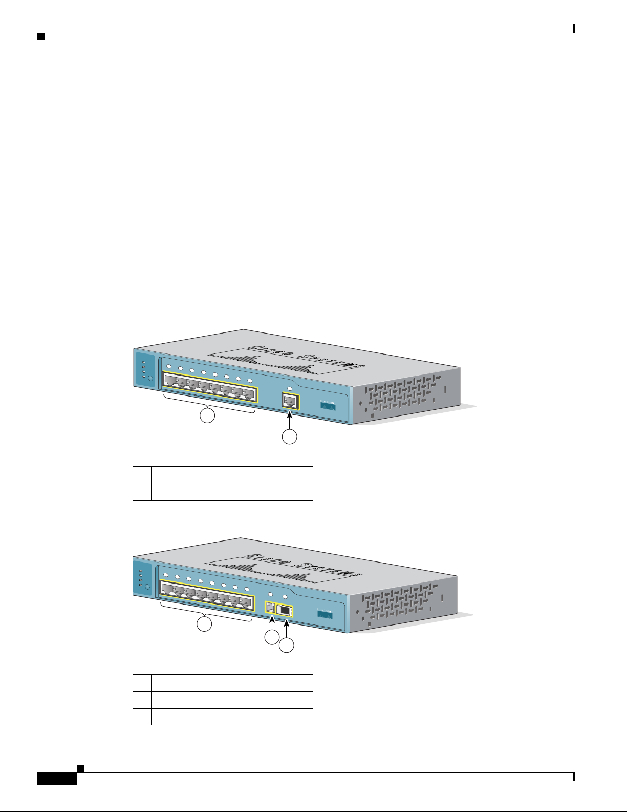
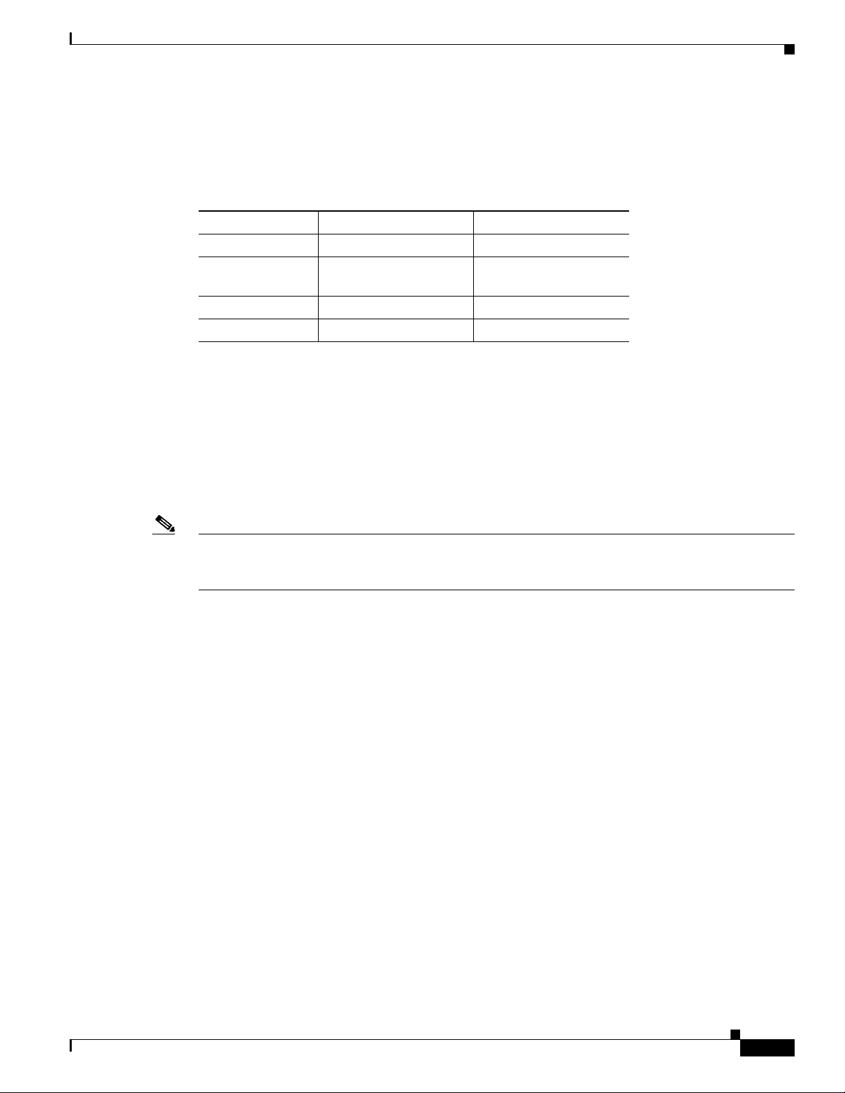
The switch front panel contains the ports, the LEDs, and the Mode button.
Figure 1-1 and Figure 1-2 show the switches.
Figure 1-1 Catalyst 2940-8TT-S Switch
Chapter 1 Overview
SYST
STAT
1x
2x
DPLX
SPD
MODE
3x
4x
5x
6x
7x
8x
1
1
2
1 10/100 Ethernet ports
2 10/100/1000 Gigabit Ethernet port
Figure 1-2 Catalyst 2940-8TF-S Switch
SYST
STAT
1x
2x
DPLX
SPD
MODE
3x
4x
5x
6x
7x
8x
9
1
100Base-FX
SFP
1
2
3
Catalyst 2940
Catalyst 2940
SERIES
89451
SERIES
89452
1-2
1 10/100 Ethernet ports
2 100BASE-FX port
3 SFP module slot
Catalyst 2940 Switch Hardware Installation Guide
OL-6157-01
Page 3
Chapter 1 Overview
Port Numbering
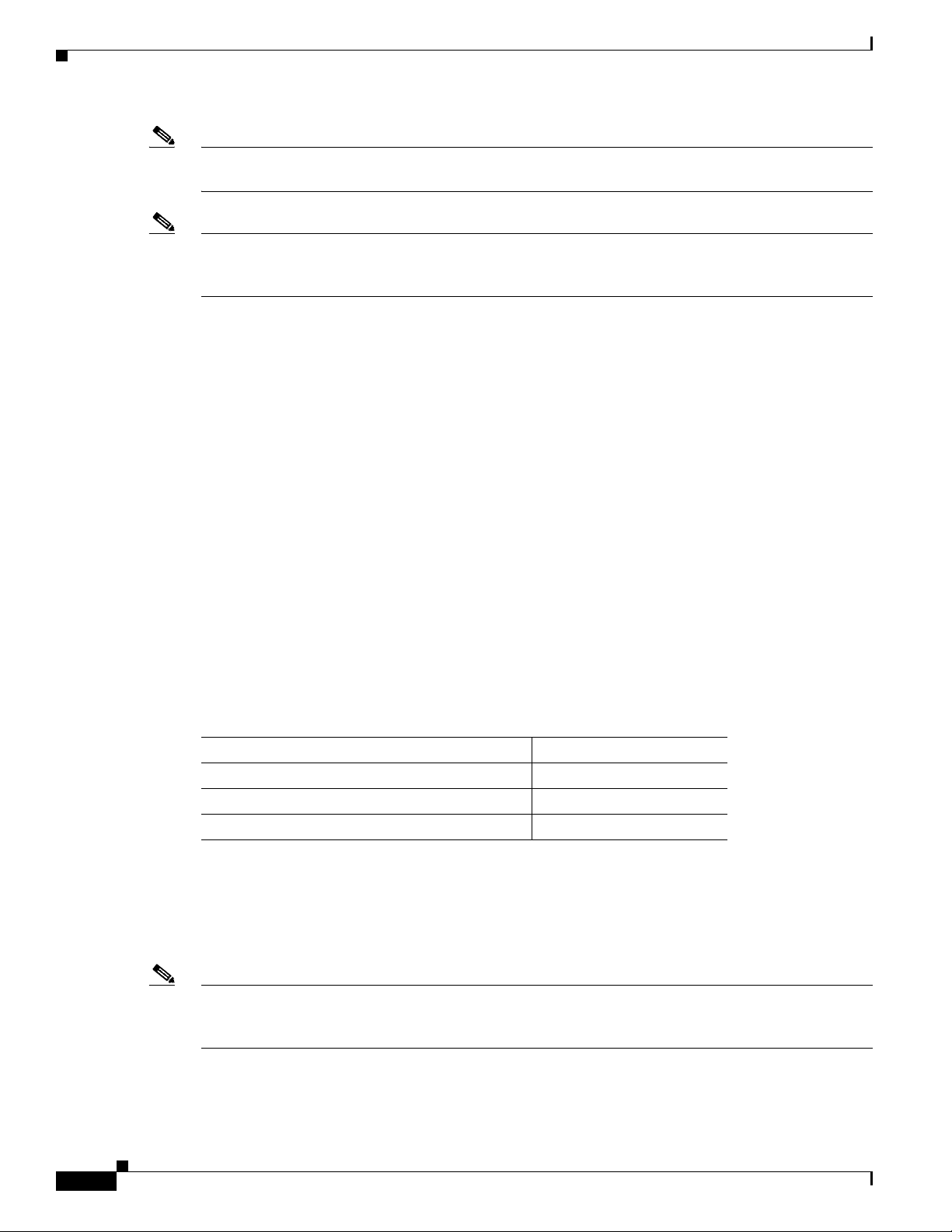
Table 1-1 lists the port and slot numbering for the Catalyst 2940 switches.
Table 1-1 Port and Slot Numbering
Port or Slot type Catalyst 2940-8TT-S Catalyst 2940-8TF-S
10/100 Ethernet 1 throug h 8 1 through 8
Gigabit Ethernet
10/100/1000
100BASE-FX — 9
SFP module — 1
10/100 Ports
The 10/100 ports use RJ-45 connectors and twisted-pair cabling. The po rts can connect to these devices:
• 10BASE-T devices, such as workstations and hubs, through standard RJ-45 connectors and two
Front-Panel Description
1—
twisted-pair cabling. You can use Category 3, 4, or 5 cabling.
• 100BASE-TX devices, such as high-speed workstations, servers, hubs, routers, and other switches,
Note When connecting the switch to workstations, servers, and routers, be sure that the cable is a twisted-pair
straight-through cable. When connecting the switch to hubs or other switches, use a twisted-pair
crossover cable. Pinouts for the cables are described in Appendix B, “Connectors and Cables.”
The 10/100 ports can be explicitly set to operate in any combination of half duplex, full dup lex, 10 Mbps,
or 100 Mbps. They can also be set for speed and duplex autonegotiation, compliant with IEEE 802.3U.
In all cases, the cable length from a switch to an attached device cannot exceed 328 feet (100 meters).
When set for autonegotiation, a port senses the speed and duplex settings of the attached device and
advertises its own capabilities. If the attached device supports autonegotiation, the port negotiates the
best connection (that is, the fastest line speed that both devices support and full-duplex transmission, if
the attached device supports it) and configures itself accordingly.
10/100/1000 Port
The 10/100/1000 port on the Catalyst 2940-8TT-S switch uses RJ-45 connectors and twisted-pair
cabling. The port can connect to these devices:
• 10BASE-T devices, such as workstations and hubs, through standard RJ-45 connectors and two or
through standard RJ-45 connectors and two or four twisted-pair, Category 5 cabling.
four twisted-pair, Category 5 cabling.
OL-6157-01
• 100BASE-TX devices, such as high-speed workstations, servers, hubs, routers, and other switches,
through standard RJ-45 connectors and two or four twisted-pair, Category 5 cabling.
• 1000BASE-T devices, such as high-speed workstations, servers, hubs, routers, and other switches,
through standard RJ-45 connectors and four twisted-pair, Category 5 cabling.
Catalyst 2940 Switch Hardware Installation Guide
1-3
Page 4
Front-Panel Description
Note When connecting the switch to a 1000BASE-T device, be sure to use a four twisted-pair, Category 5
cable.
Note When connecting the switch to workstations, servers, and routers, be sure to use a twisted-pair
straight-through cable. When connecting the switch to hubs or other switches, use a twisted-pair
crossover cable. Pinouts for the cables are described in Appendix B, “Connectors and Cables.”
The 10/100/1000 port on the Catalyst 2940-8TT-S switch can be explicitly set to operate at full- or
half-duplex at 10 or 100 Mbps. The port is restricted to full-duplex mode when it is set at 1000 Mbps.
The port can also be set for speed autonegotiation, compliant wi th IEEE 802.3AB. In all cases, the cable
length from a switch to an attached device cannot exceed 328 feet (100 meters).
100BASE-FX Port
The 100BASE-FX port on the Catalyst 2940-8TF-S switch can use either 50/125- or 62.5/125-micron
multimode fiber-optic cabling. The 100BASE-FX port operates only at 100 Mbps in full-duplex mode.
In full-duplex mode, the cable length from the 100BASE-FX port to an attached device cannot exceed
6562 feet (2 kilometers).
Chapter 1 Overview
You can use only the 100BASE-FX port or the SFP module slot at one time. When the switch is first
powered on, the 100BASE-FX port is enabled b y default. Howe v er , if an SFP module is already installed
in the switch, the SFP module slot is enabled.
You can connect the 100BASE-FX port to an SC port on a target device by using one of the MT-RJ
fiber-optic patch cables listed in Table 1-2. Use the Cisco part numbers in Table 1-2 to order the patch
cables that you need.
Table 1-2 MT-RJ Patch Cables for 100BASE-FX Connections
Type Cisco Part Number
1-meter, MT-RJ-to-SC multimode cable CAB-MTRJ-SC-MM-1M=
3-meter, MT-RJ-to-SC multimode cable CAB-MTRJ-SC-MM-3M=
5-meter, MT-RJ-to-SC multimode cable CAB-MTRJ-SC-MM-5M=
SFP Module Slot
The SFP module slot supports copper or fiber-optic SFP modules. The SFP module slot is numbered as
port 1.
Note You can use only the SFP module slot or the 100BASE-FX port at one time. When the switch is first
powered on, the 100BASE-FX port is enabled b y default. Howe v er , if an SFP module is already installed
in the switch, the SFP module slot is enabled.
1-4
If you install an SFP module after the switch has powered on, you must reload the switch to enable the
SFP module.
Catalyst 2940 Switch Hardware Installation Guide
OL-6157-01
Page 5

Chapter 1 Overview
SFP Modules
Note The Catalyst 2940-8TF-S switch only supports 1000 Mbps and full-duplex modes on SFP modules.
Front-Panel Description
The Catalyst 2940-8TF-S switch uses a field-replaceable SFP module to establish Gigabit connections.
You insert an SFP module into the SFP module slot on the front of the switch.
The Cisco SFP modules that are supported by the Catalyst 2940-8TF-S switch include:
• 1000BASE-LX, fiber-optic
• 1000BASE-SX, fiber-optic
• 1000BASE-T, copper
• Coarse Wavelength-Division Multiplexing (CDWM), fiber-optic
The 1000BASE-LX and 1000BASE-SX S FP modules are used to establish fiber-optic connections. You
use fiber-optic cables with LC connectors to connect to an SFP module. The SFP modules support 850
to 1550 nm nominal wavelengths. These field-replaceable modules pro vide the uplink optical interfaces,
laser send (TX), and laser receive (RX).
The restrictions are that each port must match the wave-length specifications on the other end of the
cable, and the cable must not exceed the stipulated cable length for reliable communications. Table 1-3
lists these stipulations.
Table 1-3 Cabling Stipulations for Fiber-Optic SFP Modules
62.5/125 micron
SFP
Module
Multimode
850 nm
SX 275 m
200 Mhz-km
1
Fiber
2
at
50/125 micron
Multimode
850 nm Fiber
550 m at
500 Mhz-km
62.5/125 micron
Multimode
1310 nm Fiber
LX — — 550 m at
500 Mhz-km
CWDM
3
1470, 1490, 1510,
SMF 9/125 — 62 miles (100
1530, 1550, 1570,
1590, 1610
1. nm = nanometer
2. m = meter
3. CWDM = Coarse Wavelength-Division Multiplexing
The 1000BASE-T SFP module is used to establish a Gigabit Ethernet connection through a Category 5
(copper) cable. This module can provide a Gigabit Ethernet connection of up to 100 meters through a
Category 5 cable.
Use only Cisco SFP modules on the Catalyst 2940-8TF-S switch. Each SFP module has an internal serial
EEPROM that is encoded with security information. This encoding pro vides a w ay for Cisco to i dentify
and validate that the SFP module meets the requirements for the switch.
50/125 micron
Multimode
1310 nm Fiber
550 m at
400 Mhz-km
8micron
9/125 micron
Single-mode
1310 nm Fiber
Single-mode
Dispersion
Shifted Fiber
—
10 km —
1470, 1490,
km)
1510, 1530,
1550, 1570,
1590, 1610
OL-6157-01
Catalyst 2940 Switch Hardware Installation Guide
1-5
Page 6

Front-Panel Description
89453
Cable Guard
LEDs
Chapter 1 Overview
The Cisco CWDM SFPs operate on single-mode fiber. The SFPs support both Gigabit Ethernet as well
as fiber channel (1 Gigabit and 2 Gigabit) links. For more information about Cisco CWDM SFPs, see
the Cisco CWDM SFP Transceiver Compatibility Matrix at this URL:
http://www.cisco.com/en/US/products/hw/modules/ps4999/products_device_support_table09186a00803bf095.html
Also see your SFP module documentation and the Cisco Small Form-Factor Pluggable Modules
Installation Notes (not orderable but is available on Cisco.com).
For the latest information about SFP modules supported by the switch, see the release notes.
You can order an optional cable guard to secure cables to the front of the switch and prevent them from
being accidentally removed. To order a cable guard, contact your Cisco repres entative.
There are four LEDs on the left panel of the switch, and there are port status LEDs above all the switch
ports, as shown in Figure 1-3.
Figure 1-3 LEDs on Catalyst 2940 Switches
1
SYST
3
4
6
STAT
DPLX
5
SPD
MODE
1x
2x
3x
4x
5x
2
1 Port status LED 4 STAT LED
2 Mode button 5 DPLX LED
3 SYST LED 6 SPD LED
You can use these LEDs to monitor switch activity and performance:
• The system (SYST) continually displays the system status. The SYST LED color shows the switch
status.
• The status (STAT), duplex (DPLX), and speed (SPD) LEDs show the information that is being
displayed by the port status LEDs. Pressing the Mode button cycles the LEDs through th e STAT,
DPLX, and SPD displays.
1-6
Catalyst 2940 Switch Hardware Installation Guide
OL-6157-01
Page 7

Chapter 1 Overview
SYST LED
Front-Panel Description
All of the LEDs described in this section are visible through the GUI management applications—the
Network Assistant application for multiple switches and the device manager for a single switch. The
switch software configuration g uide describes ho w to use the CLI to conf igure and to monitor indi vidual
switches and switch clusters.
The SYST LED shows whether the system is receiving power and functioning properly. Table 1-4 lists
the LED colors and meanings.
Table 1-4 System LED
Color System Status
Off System is not powered on.
Green System is operating normally.
Amber System is receiving power but is not functioning properly.
For information about the system LED colors during the power-on self-test (POST), see the
“Understanding POST Results” section on page 3-1.
STAT, DPLX, SPD, and Port LEDs
Press the Mode button to cycle through the STAT, DPLX, and SPD LED displays. When the LED is
highlighted for the mode that you want, release the button to enable that highlighted mode.
Table 1-5 lists the mode meanings.
Table 1-5 Port Mode LEDs
Mode LED Port Mode Description
STAT Port status Port status. This is the default mode.
DPLX Port duplex mode Port duplex mode: half duplex or full duplex.
SPD Port speed Port operating speed: 10 or 100 Mbps for 10/100 ports and
Each port has a port status LED, also called a port LED. These LEDs display information about the
individual ports. When you change the port mode, the meanings of the port LED colors change.
Table 1-6 explains how to interpret these colors.
10, 100, or 1000 Mbps for 10/100/1000 ports.
OL-6157-01
Catalyst 2940 Switch Hardware Installation Guide
1-7
Page 8

Front-Panel Description
Table 1-6 Meaning of Port LED Colors in Different Modes
Port Mode Color Meaning
STAT Off No link.
Solid green Link present.
Flashing green Activity. Port is sending or receiving data.
Alternating
green-amber
Solid amber Port is not forwarding. Port was disabled by management, an address
DPLX Off Port is operating in half duplex.
(half or
Green Port is operating in full duplex.
full
duplex)
SPD 10/100 ports
Off Port is operating at 10 Mbps.
Green Port is operating at 100 Mbps.
10/100/1000 ports
Off Port is operating at 10 Mbps.
Green Port is operating at 100 Mbps.
Flashing green Port is operating at 1000 Mbps.
SFP modules
Off Port is operating at 10 Mbps.
Green Port is operating at 100 Mbps.
Flashing green Port is operating at 1000 Mbps.
Link fault. Error frames can affect connectivity, and errors such as
excessive collisions, CRC errors, and alignment and jabber errors are
monitored for a link-fault indication.
violation, or Spanning Tree Protocol (STP).
Note After a port is reconfigured, the port LED can remain amber for
up to 30 seconds while STP checks the switch for possible loops.
Chapter 1 Overview
1-8
Catalyst 2940 Switch Hardware Installation Guide
OL-6157-01
Page 9

Chapter 1 Overview
Rear-Panel Description
The rear panel of the switches, as shown in Figure 1-4, have an AC power connector and an RJ-45
console port.
Figure 1-4 Catalyst 2940 Switch Rear Panel
1
1 AC power connector
2 RJ-45 console port
Rear-Panel Description
2
89886
Power Connector
You provide power to a switch by using the AC int er nal power supply. The internal AC power supply is
an autoranging unit that supports input volt ages between 100 and 240 VAC. Use the supplied AC power
cord to connect the AC power connector to an AC power outlet.
The switch accessory kit includes an L-shaped AC power cord. Table 1-7 lists the spare L-shaped AC
power cords that you can order from your Cisco sale s representative.
Table 1-7 Spar e L-Shaped Power Cords
Type Cisco Part Number
110 V CAB-AC-RA=
Argentina CAB-ACR-RA=
Australia, 10 A CAB-ACA-RA=
China CAB-ACC-RA=
Europe CAB-ACE-RA=
Italy CAB-ACI-RA=
Japan CAB-JPN-RA=
Switzerland CAB-ACS-RA=
UK CAB-ACU-RA=
OL-6157-01
Catalyst 2940 Switch Hardware Installation Guide
1-9
Page 10

Rear-Panel Description
Console Port
Security Slots
Chapter 1 Overview
You can connect a switch to a PC throug h the console port by using a RJ-45-to-DB-9 adapter ca ble.
If you want to connect a switch to a terminal, you need to provide an RJ-45-to-DB-25 female DTE
adapter. You can order a kit (part number ACS-DSBUASYN=) with that adapter from Cisco.
For console-port and adapter-pinout information, see the “Cable and Adapter Specif ications” section on
page B-5.
The switches have security slots in the left and right side panels. You can install an optional cable lock,
such as the type that is used to secure a laptop computer, to secure either or both sides of the switch.
Figure 1-5 shows the slot on a left-side panel.
Figure 1-5 Switch Left Panel
93001
1
1 Security slot
Cable locks are available from most computer accessory suppliers.
1-10
Catalyst 2940 Switch Hardware Installation Guide
OL-6157-01
Page 11

Chapter 1 Overview
Management Options
Catalyst 29 40 switch es offer these manageme nt option s:
• Network Assistant
The Network Assistant is a GUI-based application that you can inst all and run on your desktop; you
do not need a web browser to run it. You can use Network Assistant to manage and monitor switch
clusters or standalone devices. For more information, see the Getting Started with Cisco Network
Assistant guide and the Network Assistant online help.
• Device manager
You can use the device manager, which is in the switch memory, to manage individual and
standalone switches. The device manager is accessible after you have run the Express Setup program
(see the getting started guide for more information about running Express Setup). Use the device
manager to perform basic switch configuration and monitoring. You can access the device manager
from anywhere in your network through a web browser.
T o launch the device manager, enter the switch IP address in the web browser , and press Enter. The
device manager page appears.
See the device manager online help for more information.
• Cisco IOS CLI
You can manage switches by using command-line entries. To acce ss the CLI, connect a PC or a
terminal directly to the console port on the switch . If the switch is attached to your network, y ou can
use a Telnet connection to manage the switch from a remote location. For more information about
the CLI, see the switch command reference.
Management Options
• CiscoView application
You can use the CiscoView device-management application to set configuration parameters and to
view switch status and performance information. This application, which you purchase separately,
can be a standalone application or part of an Simple Network Management Protocol (SNMP)
network-management platform. For more information, see the documentation that came with your
CiscoView application.
• SNMP network management
You can ma nage swit ches by using an SNMP-co mpatib le manage ment statio n runnin g platforms
such as HP OpenView and SunNet Manager. The switch supports a comprehensive set of MIB
extensions and MIB II, the IEEE 802.1D bridge MIB, and four Remote Monitoring (RMON) groups.
For more information, see the documentation that came with your SNMP application.
OL-6157-01
Catalyst 2940 Switch Hardware Installation Guide
1-11
Page 12

Management Options
Chapter 1 Overview
1-12
Catalyst 2940 Switch Hardware Installation Guide
OL-6157-01
 Loading...