

Page 1

Equipment information
and assembly guide for your AT&T Service
© 2013 AT&T Intellectual Property. All rights reserved. AT&T, Globe logo and other marks are trademarks of AT&T Intellectual Property.
Please ensure that you have set-up the equipment before the date scheduled
with your AT&T Order Manager for Test and Turn Up of your site
Page 2

The following components are included in your router package:
What’s in the Box
© 2013 AT&T Intellectual Property. All rights reserved. AT&T, Globe logo and other marks are trademarks of AT&T Intellectual Property.
2
USRobotics V.Everything
56K Analog Corporate
Modem
Cisco 2911 Router
Modem power cable
Router power cable
RJ11 modem cable
Labelled ISE644
Console Cable
Multiple RJ48 Cables
Labelled ISE642
Site Documentation
Package
Page 3

Understanding your Router
Rear View of Cisco 2911
GE0/1
GE0/2
GE0/0
Front View of Cisco 2911
Power
Socket
On/Off Switch
© 2013 AT&T Intellectual Property. All rights reserved. AT&T, Globe logo and other marks are trademarks of AT&T Intellectual Property.
3
CTRLR T1
Serial 0
CTRLR T1
Serial 1
CTRLR T1
Serial 0
RJ-45 Console Port
EHWIC
Card 0
EHWIC
Card 1
EHWIC
Card 2
EHWIC
Card 3
Page 4
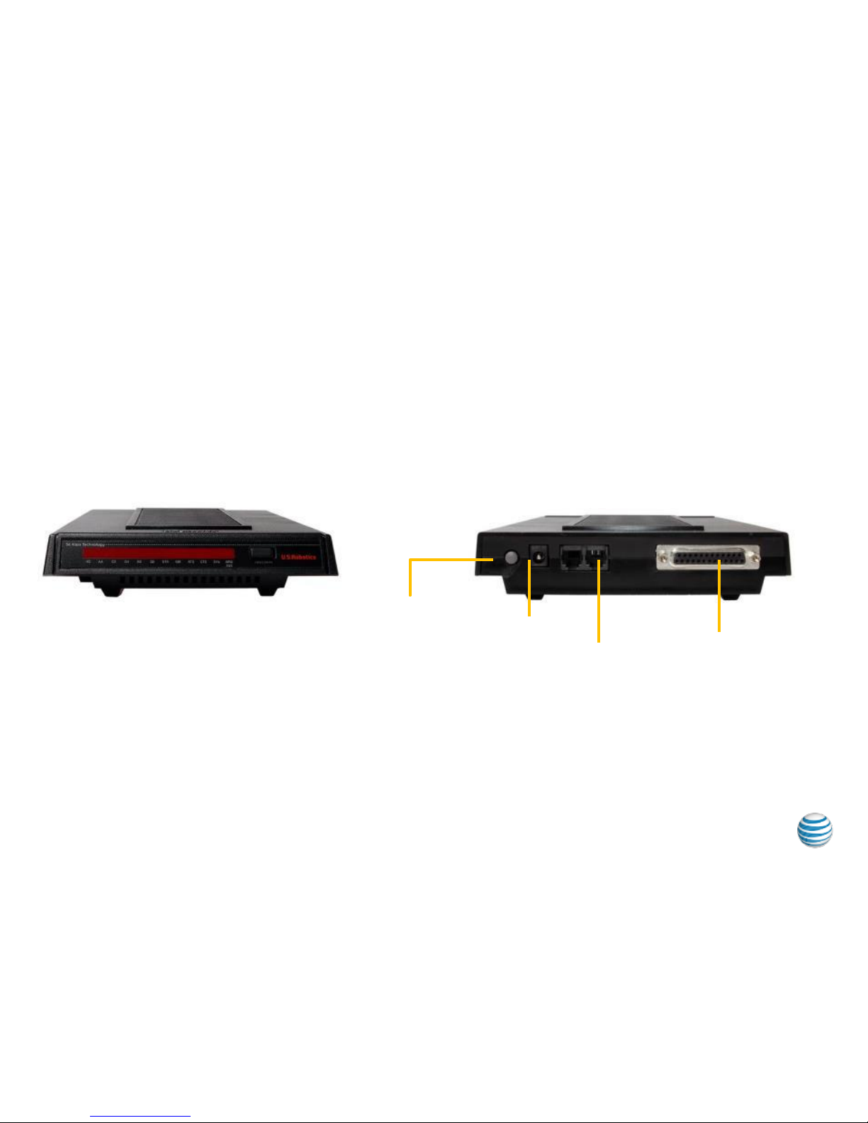
Understanding your Modem
Front View of modem
Rear View of modem
Power
Input
Power
on/off
RJ11
in/out use
port
marked
‘Jack’
RJ-45
Console Port
© 2013 AT&T Intellectual Property. All rights reserved. AT&T, Globe logo and other marks are trademarks of AT&T Intellectual Property.
4
Page 5

Step 1 Secure Modem
Secure modem on top of router – with front face of modem and front face
of router facing outwards
© 2013 AT&T Intellectual Property. All rights reserved. AT&T, Globe logo and other marks are trademarks of AT&T Intellectual Property.
5
Page 6
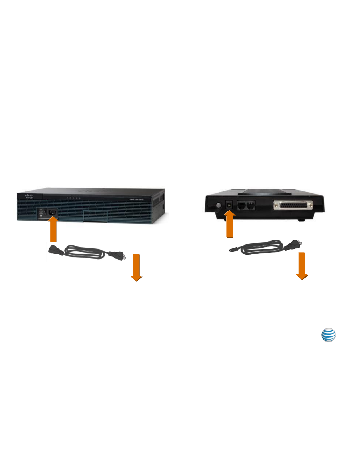
Step 2 Attach Power Cables to Router and Modem
© 2013 AT&T Intellectual Property. All rights reserved. AT&T, Globe logo and other marks are trademarks of AT&T Intellectual Property.
6
Plug in power cord to router Plug in power cord to modem
To power
receptacle
To power
receptacle
Page 7

Step 3 Connect POTS to Modem and Console Cable to
Router
Connect telephone line (analog
POTS line) from modem to wall jack
using RJ11 cable
Connect console cable to the lower
right, blue-edged console port in
router
© 2013 AT&T Intellectual Property. All rights reserved. AT&T, Globe logo and other marks are trademarks of AT&T Intellectual Property.
7
To wall jack
RJ11 modem cable
Labelled ISE644
Page 8

Step 4 Connect Console Cable to Modem
Connect console cable to modem
© 2013 AT&T Intellectual Property. All rights reserved. AT&T, Globe logo and other marks are trademarks of AT&T Intellectual Property.
8
If there are dual routers and a Call
Director refer to Service Director
Assembly Guide for alternate step 4
Page 9
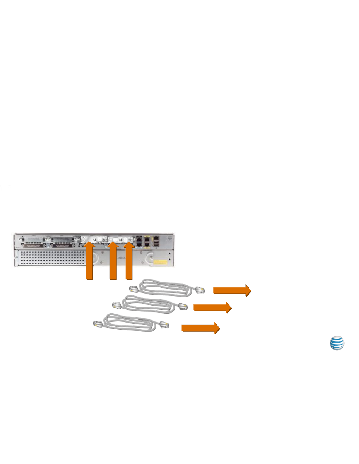
Step 5 Connect Router to Access Circuits
Connect multiple T1 circuits to ports in EHWIC card slots ensuring correct
mapping of Serial ports to Circuits per instructions in your Site
Documentation Package.
This step may need to be performed at Test and Turn Up to ensure
mappings are correct.
© 2013 AT&T Intellectual Property. All rights reserved. AT&T, Globe logo and other marks are trademarks of AT&T Intellectual Property.
9
Cables labelled ISE642
To mapped
circuit
To mapped
circuit
To mapped
circuit
Page 10

Step 6 Connect Router to your Local Network
For connection, plug Ethernet cable RJ45 into GE0/1 port on back of router
(Lower right) or per instructions in your Site Documentation Package.
© 2013 AT&T Intellectual Property. All rights reserved. AT&T, Globe logo and other marks are trademarks of AT&T Intellectual Property.
10
Customer provide
LAN Cable
Other end of Ethernet cable can be plugged into server, computer,
private network, etc.
Power on installed equipment.
 Loading...