

Page 1

Catalyst 2900 Series XL
Hardware Installation Guide
April 2001
Corporate Headquarters
Cisco Systems , Inc.
170 West Tasman Drive
San Jose, CA 95134-1706
USA
http://www.cisco.com
Tel: 408 526-4000
800 553-NETS (6387)
Fax: 408 526-4100
Customer Order Number: DOC-786461=
Text Part Number: 78-6461-03
Page 2

THE SPECIFICATIONS AND INFORMATION REGARDING THE PRODUCTS IN THIS MANUAL ARE SUBJECT TO CHANGE WITHOUT
NOTICE. ALL STATEMENTS, INFORMATION, AND RECOMMENDATIONS IN THIS MANUAL ARE BELIEVED TO BE ACCURATE BUT
ARE PRESENTED WITHOUT WARRANTY OF ANY KIND, EXPRESS OR IMPLIED. USERS MUST TAKE FULL RESPONSIBILITY FOR
THEIR APPLICATION OF AN Y PRODUCTS.
THE SOFTWARELICENSE AND LIMITED WARRANTY FOR THE ACCOMPANYING PRODUCT ARE SETFORTH INTHE INFORMATION
PACKET THAT SHIPPED WITH THE PRODUCT AND ARE INCORPORATED HEREIN BY THIS REFERENCE. IF YOU ARE UNABLE TO
LOCATE THE SOFTWARE LICENSE OR LIMITED WARRANTY, CONTACT YOUR CISCO REPRESENTATIVE FOR A COPY.
The following i nform ati on is for FCC c ompli ance of Class A devices:This equipment has been tested and found to comply with t he limits for a Class
A digital device, pursuant to part 15 o f the FCC rules. These limits are designed to provide reasonable protectio n against harmful interfer ence when
the equipment is operated in a commercial environment. This equipment generates, uses, and can radiate radio-frequency energy and, if not ins talled
and used in accordance with the instruction manual, may cause h armful int erference to rad io commu nications. Oper ation of t his equipm ent in a
residential area is likely to cause h armful interference, in which case users will b e requi red t o correct t he int erferen ce at their own expense.
The following information is for FCC compliance of Class B devices: The equipment described in this manual generates and may rad i ate
radio-frequency energy. If it is not installed in accordance with Cisco’s installation instru cti ons, it may cause interference with radio and television
reception. This equipment has been tested and found to comply wit h the limits for a Class B digital device in accordance with the specifications in
part 15 of the FCC rules. These specifications are designed to provide reasonable protection against such interference in a r esidential installation.
However, there is no guarantee that interference will no t occur in a par ticular installati on.
Modifying the equipment withou t C isco’s written authori zatio n may resul t in the equipment no longer comply ing wi th FCC requirements for Class
A or Class B digital devices. In tha t event, your right t o us e the equ ipm ent m ay be limited by FCC regulations, and yo u may be required to correct
any interference to radio or television comm unicati ons at your own expense.
You can determine whether your equi pmen t is c ausing interference by turning it off. If the interfer ence stop s, it was p robabl y caus ed by the Cisco
equipment or one of its peripheral devices. If the equipment causes interference to r adio o r tel evision reception , tr y to co rrect th e inter ference by
using one or more of the fol lowing measures:
• Turn the television or radio antenna unt il th e i nter fe renc e sto ps.
• Move the equipment to one side or the other of the television or r adio .
• Move the equipment farther away from the television or ra dio.
• Plug the equipment in to a n out le t that is on a different circuit fro m the television or radio. (T hat is, make certain the eq ui p ment and the television
or radio are on circuits contro lled by differe nt circ uit br eakers or f uses.)
Modifications to this product no t auth ori zed by Ci sco Systems, Inc. could void the FCC approval and negate your authority to oper ate the product.
The Cisco implementation of TCP header compression is an adaptation of a program developed by the University of California, Berkeley (UCB) as
part of UCB’spubli c domain version of the UNIX operating system. All rights reserved. Copyright © 1981, Regents of the University of Califo rnia.
NOTWITHSTAN DING ANY OTHER WARRANTY HEREIN, ALL DOCUMENT FILES AND SOFTWARE OF THESE SUPPLIERS ARE
PROV IDED “AS IS” WITH ALL FAULTS. CISCO AND THE ABOVE-NAMED SUPPLIERS DISCLAIM ALL WARRANTIES, EXPRESSED
OR IMPLIED, INCLUDING, WITHOUT LIMITATION, THOSE OF MERCHANTABILITY, FITNESS FOR A PARTICULAR P URPOSE AND
NONINFRINGEMENT OR ARISING FROM A COURSE OF DEALING, USAGE, OR TRADE PRACTICE.
IN NO EVENT SHALL CISCO OR ITS SUPPLIERS BE LIABLE FOR ANY INDIRECT, SPECIAL, CONSEQUENTIAL, OR INCIDENTAL
DAMAGES, INCLUDING, WITHOUT LIMITATION, LOST PROFITS OR LOSS OR DAMAGE TO DATA ARIS ING OUT OF THE USE OR
INABILITY TO USE THIS MANUAL, EVEN IF CISCO OR ITS SUPPLIERS HAVEBEEN ADVISED OF THE POSSIBILIT Y OF SUCH
DAMAGES.
AccessPath, AtmDirector,Browse with Me, CCDA,CCDE, CCDP, CCIE, CCNA, CCNP, CCSI, CD-PAC, CiscoLink,theCiscoNetWorks logo, the
Cisco PoweredNetwork logo, Cisco Systems Netw or king Academy, the Cisco Systems Networ ki ng Academy logo, Fast S tep, Follow Me Browsing,
FormShare, FrameShare, GigaStack, IGX, Internet Quotient, IP /VC, iQ Breakt hrough , iQ Exp ertise, iQ FastTrack, t he iQ Logo , iQ Net Readin ess
Scorecard, MGX,the Networkers logo, Packet, PIX, RateMUX, S c riptB u ild er, ScriptShare, Sl ideC ast , S M ART net, TransPath, Unity, Voice LAN,
Wavelength Router, and WebViewer are t rademarks of Cisco System s, Inc.; Changing theWay We Wo rk, Live, Play, an d Learn, Discover A ll That’s
Possible, and Empowering the Internet Generation, are service marks of Cisco Systems, Inc.; and Aironet, A SIST, BPX, Catalyst, Cisco, the Cisco
Certified Internetwork Ex pert logo , Ci sco IO S, t he C isco IO S lo go, Cisco Systems, Cisco Syst ems C apital, the Cisco Systems logo,
Page 3

Enterprise/Solve r, EtherChannel, Ethe rSw it ch, FastHub, FastSwit ch, IOS, IP/TV, LightS tr ea m, MICA, Network Regis tr ar , Pos t- Rout ing,
Pre-Routing,Registrar,StrataView Plus, Stratm,SwitchProbe, TeleRouter, andVCO are registered trademarks of Cisco Systems, Inc. orits affiliates
in the U.S. and certain other co unt ries.
All other brands, names, or tradem ark s menti oned i n thi s docum ent or Web site are the property of thei r re spectiv e owner s. The use of the word
partner does not imply a partnership relationship between Cisco and any other company. (0102R)
Catalyst 2900 Series XL Hardware Installation G uid e
Copyright © 2001, Cisco Sys te ms, I nc.
All rights reserved.
Page 4

Page 5

Preface xi
Audience xi
Purpose xi
Organization xii
Conventions xii
Related Publications xvi
Obtaining Documentation xvii
World Wide Web xvii
Cisco Documentation CD-ROM xvii
Ordering Documenta tion xviii
Documentation Feedback xviii
Obtaining Technical Assistance xix
Cisco.com xix
Technical Assistance Center xix
Contacting TAC by Using the Cisco TAC Website xx
Contacting TAC by Telephone xx
CONTENTS
CHAPTER
78-6461-03
1 Product Overview 1-1
Features 1-1
Management Interf ace Options 1-4
Front-Panel Desc ription 1-5
10/100 Ports 1-6
100BASE-FX Ports 1-7
Long-Reach Ethernet Ports 1-7
Catalyst 2900SeriesXL Hardware Installation Guide
v
Page 6

Contents
Expansion Slots 1-8
LEDs 1-9
System LED 1-11
RPS LED 1-12
Port LEDs and Modes 1-13
Expansion Slot LEDs 1-17
Rear-Panel Description 1-18
Power Connectors 1-19
Internal Power Supply Connector 1-19
Cisco RPS Connector 1-19
Console Port 1-21
CHAPTER
2 Installation 2-1
Preparing for Installation 2-1
Warnings 2-1
EMC Regulatory Statements 2-4
U.S.A. 2-4
Taiwan 2-4
Hungary 2-5
Installation Guidelines 2-5
Verifying Package Contents 2-6
Installing the Switch on a Table or Shelf 2-7
Installing the Switch in a Rack 2-8
Removing Screws from the Switch 2-10
Attaching the B rackets to a Ca talyst 29 12 XL, 2924C XL, 2924 XL, 29 12MF XL,
or 2924M XL Switch 2-11
Attaching the Bra ckets to a Catalyst 2912 LRE XL or 2924 LRE XL
Switch 2-17
Mounting the Switch in a Rack 2-19
Attaching the Optional Cable Guide 2-20
vi
Catalyst 2900 SeriesXL Hardware Installation Guide
78-6461-03
Page 7

Installing the Switch on a Wall 2-22
Attaching the Brackets to the Switch 2-22
Mounting the Switch to a Wall 2-23
Powering On the Switch and Running POST 2-25
Connecting to a 10/100 Port 2-26
Connecting to a 100BASE-FX Port 2-28
Connecting to an LRE Port 2-30
Connecting to a Module Port 2-33
Connecting to the Console Port 2-33
Where to Go Next 2-34
Contents
CHAPTER
APPENDIX
APPENDIX
3 Troubleshooting 3-1
Understanding POST Results 3-2
Correcting Mo du le POST Failures 3-3
Diagnosing Problems 3-3
A Technical Specifications A-1
B Connectors and Cable Specifications B-1
Connector Specifications B-1
10/100 Ports B-1
100BASE-FX Ports B-2
LRE Ports B-3
Console Port B-3
Cable and Adapter Specifications B-4
Crossover and Straight-Through Cabl e Pinouts B-4
RJ-21 Cable Pinouts B-5
Console Port B-5
78-6461-03
Catalyst 2900SeriesXL Hardware Installation Guide
vii
Page 8

Contents
Identifying a Rollover Cable B-6
Connecting to a PC B-6
Connecting to a Terminal B-7
APPENDIX
C Translated Safety Warnings C-1
Attaching the Cisco RPS (model PWR600-AC-RPS) C-2
Attaching the Cisco RPS (model PWR300-AC-RPS-N1) C-3
Qualified Personnel Warning C-4
Installation Warning C-5
Jewelry Remo va l W a rn in g C-6
Stacking the Chassis Warning C-8
Main Disconnecting Device C-9
Overtemperature Warning C-10
TN Power Warn in g C-13
Ground Connection Warning C-14
Circuit Breaker (15A) Warning C-15
Grounded Equipment Warning C-17
Supply Circuit Warning C-18
Voltage Warnin g C-19
Power Supply W a rn in g C-21
Lightning Activity Warning C-23
viii
Product Disposal Warning C-24
Class 1 Laser Produ ct Warning C-25
Laser Beam Exposure Warning C-26
Catalyst 2900 SeriesXL Hardware Installation Guide
78-6461-03
Page 9

INDEX
Contents
No On/Off Switch Warning C-27
Chassis Warning—Rack-Mounting and Servicing C-29
78-6461-03
Catalyst 2900SeriesXL Hardware Installation Guide
ix
Page 10

Contents
Catalyst 2900 SeriesXL Hardware Installation Guide
x
78-6461-03
Page 11

Audience
Purpose
Preface
This guide is for the networking or computer technician responsible for installing
and configuring a Catalyst 2900 series XL sw itch. We assume that you are
familiar with the concepts and terminology of Ethernet and local area networking.
The Catalyst 2900 Series XL Hardware Installation Guide do cume nts the
hardware features of Catalyst 2900 series XL switches. It describes t he p hysi cal
and performance characteristics of the switches, explains how to install a switch,
and provides t roubl eshoo tin g i nfor ma tion and specifications.
78-6461-03
Catalyst 2900 Series XL Hardware Installation Guide
xi
Page 12

Organization
Organization
This guide is organized into the following chapters:
Chapter 1, “Prod uct Overview,” summarizes the switch features, and describes
the ports, the standards they support, and t he L EDs.
Chapter 2, “Installation,” provides the procedures for installing a switch in a rack,
on a desk, o r on a wall.
Chapter 3, “Troubleshooting,” describes how to identify and resolve some of the
problems that mi ght arise when you are installing th e switch.
Appendix A, “Technical S peci ficatio ns,” lists the physical and e nvironmental
specifications for the switches and the regulatory agency approvals.
Appendix B, “Connectors and Cable Specifications,” de scrib es the connector s,
cables, and adapters tha t can be used to connect t o the switch.
Appendix C, “Translated Safety Warnings,” provides translations in various
languages of the warnings in this g uide.
Preface
Conventions
This guide uses the following c onventions to convey instructions and inform ation:
Command descriptions use these conventions:
Examples us e these co nventions:
Catalyst 2900 SeriesXL Hardware Installation Guide
xii
• Commands and keywords are in boldface.
• Arguments for which you suppl y values are in italic.
• Terminal sessions a nd system displays are in screen font.
• Information you enter is in boldface screen font.
• Nonprinting cha rac ter s, su ch as passwords or tabs, are in an gle brackets (< >).
78-6461-03
Page 13

Preface
Conventions
Notes, cautions, and warnings use the following conventions and symbols:
Note Means reader take note. Notes contain helpful suggestions or references to
materials not contained in this man ual .
Caution Meansreader be careful. In this situati on, you might do something that cou ld
result in equi pmen t damage or loss of data.
Warning
Waarschuwing
Varoitus
This warning symbol means danger . You are in a situation that could cause
bodily injury. Before you work on any equipment, be aware of the hazards
involved with electrical circuitry and be familiar with standard practices
for preventing accidents. (To see t ranslations of the warnings that appear
in this publication, refer to the Appendix C, “Translated Safety Warnings.”)
Dit waarschuwingssymbool betekent gevaar. U verkeert in een
situatie die lichamelijk letsel kan veroorzaken. Voordat u aan
enige apparatuur gaat werken, dient u zich bewust te zijn van de
bij elektrische schakelingen betrokken risico’s en dient u op de
hoogte te zijn van standaard maatregelen om ongelukken te
voorkomen. (Voor vertalingen van de waarschuwingen die in
deze publicatie verschijnen, kunt u het aanhangsel C “Translated
Safety Warnings” (Vertalingen van veiligheidsvoorschriften)
raadplegen.)
Tämä varoitusmerkki merkitsee vaaraa. Olet tilanteessa, joka voi
johtaa ruumiinvammaan. Ennen kuin työskentelet minkään
laitteiston parissa, ota selvää sähkökytkentöihin liittyvistä
vaaroista ja tavanomaisista onnettomuuksien ehkäisykeinoista.
(Tässä julkaisussa esiintyvien varoitusten käännökset löydät
liitteestä C "Translated Safety Warnings" (käännetyt
turvallisuutta koskevat varoitukset).)
78-6461-03
Catalyst 2900 Series XL Hardware Installation Guide
xiii
Page 14

Conventions
Preface
Attention
Warnung
Avvertenza
Ce symbole d’avertissement indique un danger . Vous vous trouvez
dans une situation pouvant entraîner des blessures. Avant
d’accéder à cet équipement, soyez conscient des dangers posés
par les circuits électriques et familiarisez-vous avec les
procédures courantes de prévention des accidents. Pour obtenir
les traductions des mises en garde figurant dans cette
publication, veuillez consulter l’annexe intitulée C « Translated
Safety Warnings » (Traduction des avis de sécurité).
Dieses Warnsymbol bedeutet Gefahr. Sie befinden sich in einer
Situation, die zu einer Körperverletzung führen könnte. Bevor Sie
mit der Arbeit an irgendeinem Gerät beginnen, seien Sie sich der
mit elektrischen Stromkreisen verbundenen Gefahren und der
Standardpraktiken zur Vermeidung von Unfällen bewußt.
(Übersetzungen der in dieser Veröffentlichung enthaltenen
Warnhinweise finden Sie im Anhang mit dem Titel C “Translated
Safety Warnings” (Übersetzung der Warnhinweise).)
Questo simbolo di avvertenza indica un pericolo. Si è in una
situazione che può causare infortuni. Prima di lavorare su
qualsiasi apparecchiatura, occorre conoscere i pericoli relativi
ai circuiti elettrici ed essere al corrente delle pratiche standard
per la prevenzione di incidenti. La traduzione delle avvertenze
riportate in questa pubblicazione si trova nell’appendice C,
“Translated Safety Warnings” (Traduzione delle avvert enze di
sicurezza).
xiv
Advarsel
Dette varselsymbolet betyr fare. Du befinner deg i en situasjon
som kan føre til personskade. Før du utfører arbeid på utstyr, må
du være oppmerksom på de faremomentene som elektriske
kretser innebærer, samt gjøre deg kjent med vanlig praksis når
det gjelder å unngå ulykker. (Hvis du vil se oversettelser av de
advarslene som finnes i denne publikasjonen, kan du se i
vedlegget C "Translated Safety Warnings" [Oversatte
sikkerhetsadvarsler].)
Catalyst 2900 SeriesXL Hardware Installation Guide
78-6461-03
Page 15

Preface
Conventions
Aviso
¡Advertencia!
Varning!
Este símbolo de aviso indica perigo. Encontra-se numa situação
que lhe poderá causar danos fisicos. Antes de começar a
trabalhar com qualquer equipamento, familiarize-se com os
perigos relacionados com circuitos eléctricos, e com quaisquer
práticas comuns que possam prevenir possíveis acidentes. (Para
ver as traduções dos avisos que constam desta publicação,
consulte o apêndice C “Transl ated Safety Warnings” “Traduções dos Avisos de Segurança”).
Este símbolo de aviso significa peligro. Existe riesgo para su
integridad física. Antes de manipular cualquier equipo,
considerar los riesgos que entraña la corriente eléctrica y
familiarizarse con los procedimientos estándar de prevención de
accidentes. (Para ver traducciones de las advertencias que
aparecen en esta publicación, consultar el apéndice titulado C
“Translated Safety Warnings.”)
Denna varningssymbol signalerar fara. Du befinner dig i en
situation som kan leda till personskada. Innan du utför arbete på
någon utrustning måste du vara medveten om farorna med
elkretsar och känna till vanligt förfarande för att förebygga
skador . (Se förklaringar av de varningar som förekommer i denna
publikation i appendix C "T ranslated Safety W arnings" [Översatta
säkerhetsvarningar].)
78-6461-03
Catalyst 2900 Series XL Hardware Installation Guide
xv
Page 16

Related Publications
Related Publications
You can order printed copies of doc ume nts with a DOC-xxx xxx= number.
The following publi cati ons provide more infor mat ion about the s witche s:
• Release Notes for the Cat alyst 2900 Series XL a nd Cat alyst 3500 Series XL,
Cisco IOS Release 12.0(5)WC(1)
• Catalyst 2900 XL and Catalyst 3500 XL Documentation CD
Note This product- speci fic CD contains only the Catalyst 2900 XL an d
Catalyst 3500 XL switch documentsandrelatedhardwaredocuments.
This CD is not the same as the Cisco Doc umen tati on CD-ROM, which
contains the doc ument ati on for all C isco products and is s hippe d with
all Cisco products.
This CD is shipped with the switch and has the following publications:
–
This Catalyst 2900 Series XL Hardware Installation G uide
(order number DOC-786461=)
Preface
xvi
–
Catalyst 2900 Seri es XL and Catalyst 3500 Series XL Software
Configuration Guide, Cisc o IOS Release 12. 0(5)WC (1)
(order number DOC-786511=)
–
Catalyst 2900 Seri es XL and Catalyst 3500 Series XL Command
Reference, Cisco IOS R elease 12.0(5)WC(1)
(order number DOC-7812155=)
–
Catalyst 2 900 Series XL Modules I nstallation Guide
(order number DOC-CAT2900-IG=)
–
Catalyst 2900 Seri es X L ATM Module s I nstallat ion and Configuration
Guide ( ord er number DOC -7854 72= )
–
1000BASE-T Gigabit Interface Converter Instal latio n Note
(not orderable but is available on Cisco. com)
–
Catalyst GigaStack Gigab it Interface Converter Hardware Installation
Guide ( ord er number DOC -7864 60= )
Catalyst 2900 SeriesXL Hardware Installation Guide
78-6461-03
Page 17

Preface
–
Cisco 575 LRE C PE Hardware Installation Guide (order number
DOC-7811469=)
• Installation Notes for the Cisco LRE 48 POTS Splitter (o rd er number
DOC-7812250=)
Obtaining Documentation
The following sections provide sources for obtaining documentation from Cisco
Systems.
World Wide Web
You can access the most current Cisco documentation on the WorldWide Web at
the following sites:
• http://www.cisco.com
• http://www-china.cisco.com
Obtainin g Do cumentation
• http://www-europe.cisco.com
Cisco Documentation CD-ROM
Cisco documentation and additional literature are available in a CD-ROM
package, whi ch ships with your product. The Cisco D o cume ntat ion CD-ROM is
updated monthl y and may be more current than printed documentation. T he
CD-ROM pa cka ge i s available a s a single unit o r as an annual subscription.
Note This CD cont ains the document ation for all C isco products and is shipped with
all Cisco pr odu cts. This CD i s n ot the same a s the Catalyst 2900 XL an d
Catalyst 3500 XL Documentation CD, which con tains only the
Catalyst 2900 X L and Catalyst 350 0 XL switch doc ument s and related
hardware documen ts .
78-6461-03
Catalyst 2900 Series XL Hardware Installation Guide
xvii
Page 18

Obtaining Documentation
Ordering Documentation
Cisco documentation is available in the fol lowing ways:
• Registered Cisco Dir ect Customers can order Cisco Produc t documentation
from the Ne tworki ng Products Ma rketPl ace :
http://www.cisco.com/cgi-bin/order/order_root.pl
• Registered Cisco.com users can order the Documentation CD-ROM through
the online Subscriptio n Stor e:
http://www.cisco.com/go/subscription
• Nonregistered CCO users can o rder documentation through a loca l account
representative by calling Cisco corporate headquarters (California, USA) at
408 526-7208 o r, in Nor th America, by ca llin g 800 553-NETS(638 7).
Documentation Feedback
If you are reading Cisco product documentationonthe World WideWeb, you can
send us your comments by completing the online survey. When you display the
documentlistingforthisplatform,clickGive Us Your Feedback.Ifyouareusing
the product- speci fic C D a nd you are co nne cted to the Int ern et, click the
pencil-and-paper icon in th e toolbar to d ispl ay the survey. After you display the
survey, selectthemanualthat you wish to commenton.ClickSubmittosend your
comments to the Cisco documentation group.
You ca n e-mail your comments to bug-doc@cisco.com.
Preface
xviii
To submit your comments by m ai l, for your convenience m any documents cont ai n
a response car d behind the f ron t cover. Otherwise, you can ma il your comments
to the following address:
Cisco Systems, Inc.
Document Res ource Connection
170 West Tasman Drive
San Jose, C A 95134-9883
We appreciate your comments.
Catalyst 2900 SeriesXL Hardware Installation Guide
78-6461-03
Page 19

Preface
Obtaining Technical Assistanc e
Cisco provides Cisco.com as a starting point for all technical assistance.
Customers and p artner s c an obtain documentat ion, troubleshooting tips, and
sample configurations from online tools. For Cisco.com registered users,
additional tro uble shoot ing tools are available from the TAC website.
Cisco.com
Cisco.com is the foundation of a suite of interactive, networked services that
provides immediate, open access to Cisco information and resources at anytime,
from anywhere in the world. Th is highly integrated Internet applica tion is a
powerful, easy-to-use t ool for doing business w ith Cisco.
Cisco.com provides a broad range of features and services to help customers and
partners stream line business processes and improve productivity. Through
Cisco.com, you can find information about Cisco and our networking solutions,
services, and progra ms. I n ad diti on, yo u can resolve technical issues with online
technicalsupport,download and test software packages, and order Cisco learning
materials and merchandise. Valuable online skill assessment, training, and
certification programs are also available.
Customers and partners can self-register on Cisco.com to obtain additional
personalized infor ma tion and services. Registere d use rs c an orde r p rod ucts, check
on the sta tus of an orde r, access technical su ppor t, and view benefit s sp ec ific to
their relationship s with Cisco.
Obtaining Technical Assistance
To access Cisco.com, go to th e following website:
http://www.cisco.com
Technical Assistance Center
TheCiscoTACwebsiteisavailable to all customers who needtechnicalassistance
with a Cisc o product or technology that is under wa rran t y o r covered by a
maintenance contract.
78-6461-03
Catalyst 2900 Series XL Hardware Installation Guide
xix
Page 20

Obtaining Technical Assistance
Contacting TAC by Using the Cisco TAC Website
If you have a pr iorit y level 3 (P3) or priori ty level 4 (P4) problem, contact TAC
by going to the TAC website:
http://www.cisco.com/tac
P3 and P4 level problems are defined as follows:
• P3—Your network performance is degraded. Network functionality is
noticeably impaired, but most business operations continue.
• P4—You need information or assistance on Cisco product capabilities,
product installati on, or basic produc t configuration.
In e ach of the above cases, u se the Cisc o TAC web site t o quickly find answe rs to
your questions.
To register for C isco .com, go to the following website:
http://www.cisco.com/register/
If you canno t re solve y our technical issu e by using the TAC online resou rces ,
Cisco.com registered users can open a case o nline by using the TAC Case Open
tool at the following website:
Preface
http://www.cisco.com/tac/caseopen
Contacting TAC by Telephone
If you have a pr iorit y level 1 (P1) or priori ty level 2 (P2) problem, contact TAC
by telephone and immediately open a case. To obtain a directory of toll-free
numbers for y our country, go to the following we bsite:
http://www.cisco.com/warp/public/687/Directory/DirTAC.shtml
P1 and P2 level problems are defined as follows:
• P1—Your production net work is down, causing a cr itic al i mpa ct t o business
operations if service is no t restored quickly. No workar ound is available.
• P2—Your production n et work is severely degraded, affecting significant
aspects of your business op erat ion s. No workaround is available.
Catalyst 2900 SeriesXL Hardware Installation Guide
xx
78-6461-03
Page 21

Features
CHAPTER
1
Product Overview
This chapter provides the following topics that describe the
Catalyst 2900 series XL switches, hereafter referred to as the switches.
• Switch features , including manageme nt options
• Descriptions of the front and rear panels
• Descriptions of the LEDs
The switches a r e stackable 10/100 Ethernet switche s to which you can connect
workstations, Cisco IP Phones, an d o t her network devices such as servers,
routers, and other switches. The 2900 XL LRE switches employ Long-Reach
Ethernet (L RE), a very-high-data- rat e digital subscri ber line (VDSL)-based
technology that allows an Ethernet network to reach distances up to 4921 f eet
(1500 meters). T he s witche s ca n be deployed as backbo ne switches, aggregating
10/100 and Gi gabi t E ther net traffic from other ne twork devices.
The Catalyst 2900 XL switches have th ese features:
78-6461-03
• Autonegotiates spe ed and duplex oper ation on all 10/1 00 ports
• Operates in full -duplex mode on all 10 0BASE-FX ports
• Checksforerrorsonareceived packet,determines the destinationport,stores
the packet in shared memory, and then forwards the packet to the destination
port
Catalyst 2900SeriesXL Hardware Installation Guide
1-1
Page 22

Features
Chapter1 Product Overview
• On the Catalyst 2924M XL an d Catalyst 2912MF XL switches, two
expansion slots for 10BASE-T/100BASE-TX, 1 00BASE-FX, Gigabit
Ethernet, and asynchronous transfer mode (ATM) m odule s
• On the Catalyst 2912 LRE XL and 2924 LRE X L sw itch es, u p to 24 LRE
ports through o ne RJ-21 connect or
• Supports up to 2048 M AC addresses on the Catalyst 2924 X L, 2 924C XL, and
2912 XL swit ches
• Supports up to 8192 MAC addresses o n the Catalyst 29 24M XL and 2912 MF
XL switches
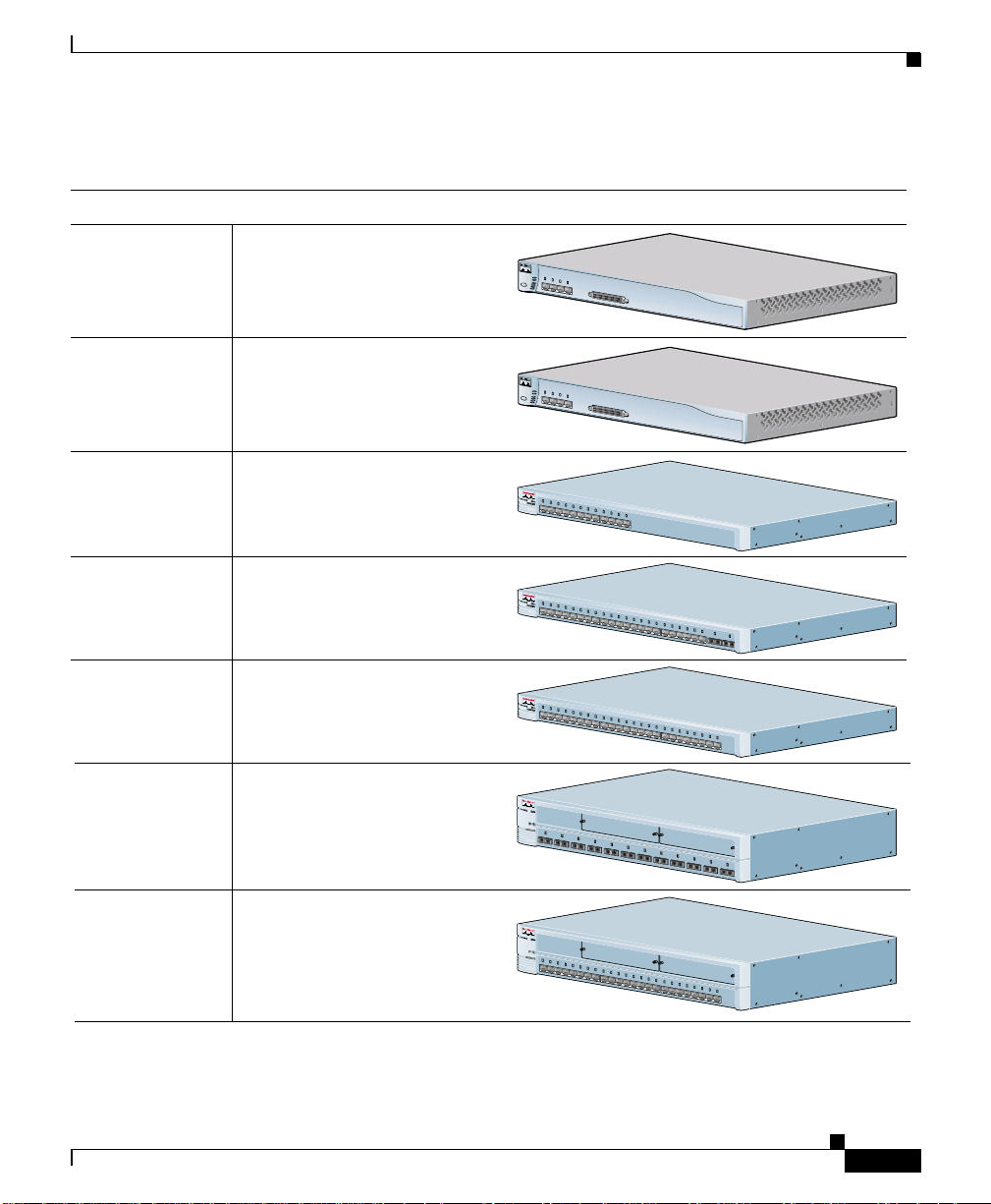
Figure 1-1 shows the switch models.
1-2
Catalyst 2900 SeriesXL Hardware Installation Guide
78-6461-03
Page 23
Chapter 1 Product Overview
Figure 1-1 Catalyst 2900 Series XL Switches
Version Number Description
WS-C2912-LRE-XL 4 fixed autosensing 10/100 ports
12 LRE ports
WS-C2924-LRE-XL 4 fixed autosensing 10/100 ports
24 LRE ports
Features
IN
P
U
T P
W
R
OU
T
P
U
T
P
W
R
9
X
R
E
S
E
T
T
E
MP
10X
1
1
X
F
A
N
12X
IN
P
U
T
P
W
R
O
U
TP
U
T P
W
R
9
X
R
E
S
E
T
T
E
M
1
P
0X
11X
F
A
N
12
X
C
isco R
P
S
3
00
C
isco R
PS
300
WS-C2912-XL 12 fixed autosensing 10/100 ports
WS-C2924C-XL 22 fixed autosensing 10/100 ports
2 100BASE-FX ports
WS-C2924-XL 24 fixed autosensing 10/100 ports
WS-C2912MF-XL 12 100BASE-FX ports
2 expansion slots
WS-C2924M-XL 24 fixed autosensing 10/100 ports
2 expansion slots
1
X
2X
3X
4
X5X
M
O
D
E
6
X
7X
1
0
B
8
a
X
s
e
T
/
1
0
0
B
A
S
9
X
E
T
X
10
X
1
1X
1
2
X
1
X
2X
3
X
4
X5X
M
O
D
E
6
X
7
X
1
0
B
A
8
S
X
E
T
/
1
0
0
B
A
9
S
X
E
T
X
10
X
11
X
12
X
1
3X
14
X
15
1X
2X
3X
4X
M
O
5X
D
E
6X
7X
1
0
B
A
8X
S
E
-
1
T
0
/
0
1
B
0
0
a
B
s
A
e
9X
F
S
X
E
T
X
1
0X
1
1X
1
2X
1
3X
14
X
1
2
1
2
M
O
D
E
3
4
1
0
0
B
A
S
E
F
X
5
6
7
1
2
1X
1X
2X
2X
3
3
X
X
4X
4X
M
O
5X
5X
D
E
6X
6X
7X 8X
7X 8X
1
0
0
B
a
s
e
9X
9X
F
X
1
1
0X
0X
11X
11X
12
12
X
X
13X
13X
14X 15X
14X 15X
C
a
ta
ly
st 2
9
0
0
S
ER
IE
X
S
L
X
16
X
C
17
a
X
t
a
ly
st
18
2
X
9
0
0
1
9
X
S
ER
IES
X
20
L
X
1
0
0
B
A
S
21
E
X
F
X
2
2X
2
2
3
3
2
2
4
4
1
6X
C
17
a
X
ta
ly
s
t 2
1
8X
9
0
0
19
X
SERIES
X
2
0X
L
2
1
X
22
X
23X
24
X
C
a
ta
ly
s
t 2
9
0
0
S
E
R
IE
X
S
8
1
1
6X
6X
17X
17X
1
1
8X
8X
L
9
1
0
1
1
1
2
C
a
ta
ly
s
t 2
9
0
0
S
E
R
IE
X
S
L
19
19
X
X
20X
20X
2
2
1X
1X
22X
22X
23
X
24
X
47294
78-6461-03
Catalyst 2900SeriesXL Hardware Installation Guide
1-3
Page 24

Features
Management Interface Options
The Catalyst 2900 XL and Catalyst 3500 XL switches are designed for
plug-and-play o per ation : you only ne ed to assign bas ic IP informatio n t o the
switch and connect it to the other devices in your network. If you have specific
network needs, you c an configure and monitor the switch —on an individual basis
or as part of a switch cluster—through its various management interfaces.
You can configure and m onitor individual switches and switch clusters by using
the following interfaces:
• Cluster Management Suite (CMS)—CMS is a graphical user interface that
canbelaunchedfromanywhereinyournetworkthroughawebbrowsersuch
as Netscape Communicator or Microsoft Internet Explorer. CMS is already
installedontheswitch,andnoadditionalinstallationis required.UsingCMS,
you can fully configure and monitor a standalone switch, a sp ecific cluster
member,or an entire switch cluster.You can also display network topologies
to gather link information, and display switch images to modify switch- and
port-level settings.
• Command-line Interface (CLI)—TheswitchCLICiscoIOSsoftwareandis
enhanced to sup port desktop- switc hing feature s. You can fully configure and
monitor th e switch a nd switch cluster m embe rs from the CLI. You can access
the CLI either by connecting your management station directly to the switch
console port or by using Telnet from a remote manage ment station.
Chapter1 Product Overview
1-4
• Simple network managem en t protoco l (SNMP) —SNMP provides a means to
monitor and control the s witch and switch cluster members. You can manage
switch configuration settings, performance, security, and collect statistics by
using SNMP m anage men t applications such as CiscoWorks2000 LAN
Management Suite (LMS) and H P OpenView.
You can manage the switch from an SNMP-compatible management station
that is runn ing platforms such as HP Op enView or SunNet Manager. Th e
switch supports a comprehensive set of M IB extensions and f our Remote
Monitoring (RMO N) groups.
For more inform ation about CMS, the CLI, and SNMP refer to the Catalyst
2900 Series XL and Catalyst 3500 Series XL Software Configuration Guide.
Catalyst 2900 SeriesXL Hardware Installation Guide
78-6461-03
Page 25
Chapter 1 Product Overview
Front-Panel Description
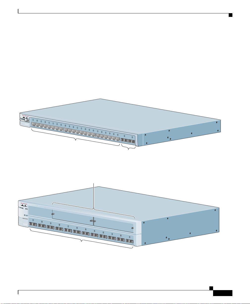
Depending on the model, the switch front panels can have up to 24 10/100 ports
(See Figure 1-2), up to 12 100BASE-FX ports (See Figure 1-2), 2 expansion slots
(see Figure 1-2), and up to 24 Long-Reach Ethernet ports (See Fig ure 1-4). All
switches have a set of LEDs and a Mode button. This section describes these
front-panel components.
Figure 1-2 Catalyst 2900 XL Front-Panel 10/100 Ports
1
1
X2X
X2X
3
3
X
X
4
4
X
M
O
D
E
X
5
5
X
X
6
6
X
X
7
7
X
X
8
8
1
0
B
A
X
X
S
E
-T
1
0
/1
0
0
B
0
a
B
s
A
9
9
X
X
e
F
S
X
E
-T
X
1
1
0
0
X
X
1
1
1
1
X
X
1
1
2
2
X
X
1
1
3
3
X
X
1
1
4
4
X
X
1
1
5
5
X
X
1
1
6
6
X
X
1
1
7
7
X
X
1
1
8
8
X
X
1
1
9
9
X
X
Catalyst 2900
2
2
0
0
X
X
100BA
2
2
1
1
SE
X
X
2
2
2
2
X
X
2
2
3
3
10/100 ports
100BASE-FX ports
Front-Panel Description
52646
S
E
R
IE
XL
S
-FX
2
2
4
4
Figure 1-3 Catalyst 2900 XL 100BASE-FX ports and Expansion Slots
Expansion slots
1
2
1
M
O
D
E
78-6461-03
2
3
4
1
0
0
B
A
S
E
-
F
5
X
6
7
8
9
100BASE-FX ports
Catalyst 2900
S
E
R
IE
XL
S
1
0
1
1
1
2
Catalyst 2900SeriesXL Hardware Installation Guide
47286
1-5
Page 26
Front-Panel Description
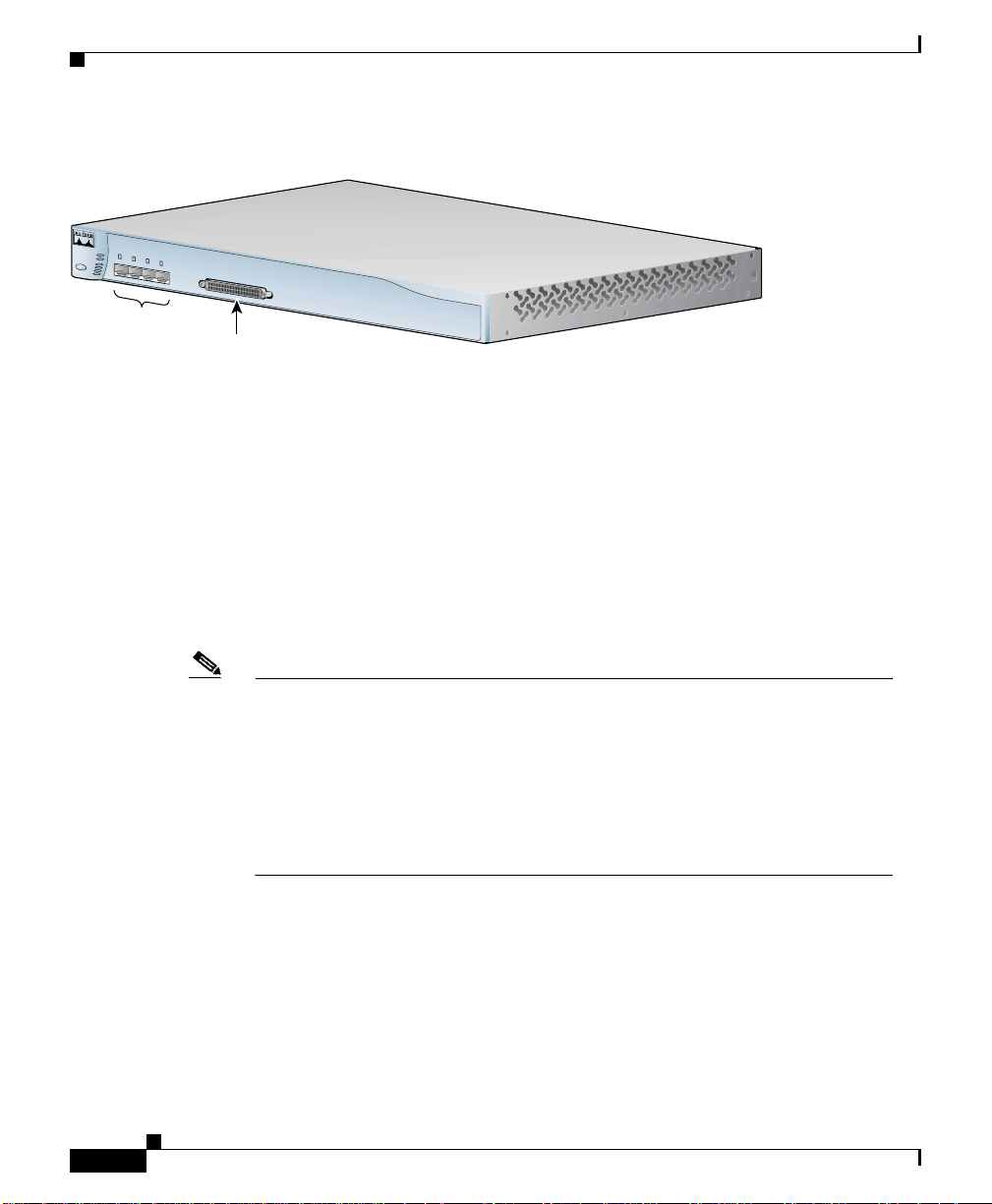
Figure 1-4 Catalyst 2900 LRE XL 10/100 and LRE Ports
INPUT PWR
OUTPUT PWR
9
X
RESET
TEMP
1
0
X
1
1
FAN
X
1
2
X
Catalyst 2900 LRE XL
10/100 ports
LRE ports
10/100 Ports
The 10/100 switch ports (see Figure 1-2 an d Figure 1-4) can connect to any
compatible ne twork device up to 328 feet (100 meters) away:
• 10BASE-T-compa tibl e devices, such as workstat ions, Cisco IP Phon es, and
hubs through standard RJ-45 connectors an d Category 3, 4, or 5 cablin g
• 100BASE-TX-compatible devices, such as high-speed workstations,
Cisco IP Phones, servers, hubs, router s, and oth er switch es throug h standar d
RJ-45 connectors and Category 5 cabling
Chapter1 Product Overview
48005
1-6
Note A Category 5 cable is requir ed for 100BASE-TX traffic. A port operating at
10BASE-TcanuseCategory3and4cables.
When connecting the switch to workstations, servers, routers, and Cisco IP
Phones, be sure t hat the cable is a straight-through, t wiste d-pa ir ca ble . W hen
connecting the switch to switch es or hubs, use a crossover cable. Pinou ts fo r
the cables are described in Appendix B, “Connect ors and Cable
Specifications.”
The 10/100 switch ports c an be explicitly set to operate in any combinat ion of
half duplex, fu ll duplex, 10 Mbps, or 100 Mbps. These ports also can be set for
speed and dupl ex aut onegotia tio n, compliant with IEEE 802.3u. W he n s et f or
autonegotiation, the port senses the speed a nd duplex settings of the atta ch ed
device and advertises its own capabilities. If the connected device also supports
autonegotiation, the switch port negotiates the best con nection (that is, the fastest
line speed that both devices support and full-duplex transmission if the attached
device supports it) and configures itself accor dingly.
Catalyst 2900 SeriesXL Hardware Installation Guide
78-6461-03
Page 27

Chapter 1 Product Overview
The 10/100 ports on the Catalyst 2900 XL switches provide proto col sup port f or
Cisco IP Phones and per-port priority override. Refer to the Catalyst 2900 Se ries
XL and Catal yst 3500 Series XL Software Configuration Guide for more
information a bout these feature s.
Cisco IP Phones—connected to the 10/100 port—must be connected to an AC
power source. Unlike the 3524-PWR X L switch, the C atal yst 2900 XL switch es
do not provide inline power.
For more info on the Catalyst 352 4-PW R X L switch, refer to the
Catalyst 3 500 Series XL Hardware I nstallation Guide.
100BASE-FX Ports
The 100BASE-FX ports use 10/125- or 62.5/125-micron multimode fiber-optic
cabling. The connection distances between the switch and the attached device can
be as follows:
• If the swit ch port and th e port on the attached device are configured for
half-duplex ope ratio n, the connectio n can be up t o 1352 feet (4 12 meters).
100BASE-FX Ports
• If the swit ch port and th e port on the attached device are configured for
full-duplex op er ati on , the conn ec ti on can be over dis ta nces of u p to 65 62 feet
(2 kilometers).
Long-Reach Ethernet Ports
The Long-Reach Ethernet (LRE) ports (Figure 1-4) use one RJ-21 connec tor to
connect up to 24 Cisco 575 LRE customer premises equipm en t (CPE ) devices
though unstructured w iring , su ch as existing telephone lines. The link between t he
LREswitchportandeachCPEdevicecanreachspeedsofupto15Mbps(full
duplex) and dist ances of up to 4921 feet ( 1500 meters).
The default mo de for each L RE port is speed autonegotiation, half duplex
operation. For i nfor matio n about configuring the LRE ports, refer to the Catalyst
2900 Series XL and Catalyst 3500 Series XL Software Configuration Guide.
For more information about the Cisco 575 LRE CPE, refer to th e Cisco
575 LRE CPE Hardware Installation Guid e.
78-6461-03
Catalyst 2900SeriesXL Hardware Installation Guide
1-7
Page 28

100BASE-FX Ports
Note If a connection to a phone network is not required at all, a splitter is not
Chapter1 Product Overview
If telephone services, suc h as voice or integrated serv ices digital ne twork (ISDN),
use the same cabling as LRE traffic, the L RE port must be connected to the patch
panel through a b asic telephone service, also known as plain old te lephone service
(POTS) splitter. The splitter routes LRE data (high-frequency) and voice
(low-frequency) traffic from the telephone line to t he switch and private branch
exchange (PBX) swi tch or public-switched telephone net work ( PSTN)
If the other telephone services are connected thr oug h a private branch exchan ge
(PBX) switch, a Cisco LRE 48 POTS Splitter can be used. The PBX routes voice
traffic to private tel ephon e networks and the public system t elepho ne network
(PSTN). For more information about the Cisco LRE 48 POTS Splitter
(PS-1M-LRE-48), re fer to the Installation Notes for the Cisco LRE 48 POTS
Splitter.
If the installation does not have a PBX, a homologated POTS splitter is required
to d irectly con nect to the PSTN. For more information about homol ogated POTS
splitters, contact y our Cisco sales representative.
needed, and the switch can connect directly to the patch panel.
Expansion Slots
The expansion slots (see Figure 1-2) are for the Catalyst 2900 XL hot-swappable
modules. Each module port is in ternally switched to other switch ports and is
managed throu gh the switch m an agem en t interfaces.
Table 1-1 lists the modules that the expansion slots support.
Table 1-1 Expansion Modules
Module Ty pe Model Number
10/100 Etherne t WS-X2914-XL
100 BASE-FX WS-X2922-XL-V
Catalyst 2900 SeriesXL Hardware Installation Guide
1-8
WS-X2914-XL-V
WS-X2922-XL
WS-X2924-XL-V
78-6461-03
Page 29

Chapter 1 Product Overview
Table 1-1 Expansion Modules (continued)
Module Ty pe Model Number
1
Ethernet Gigab it WS-X2931-XL
ATM WS-X2971-XL
1. Accommodates modules W S-G5484 =,
These modules automatically configure themselves when you insert them in
expansion slots and tighten the thumb screws. A power-on self-test (POST)
verifies that the module is working properly before it starts forwarding packets.
Modules WS-X29 14-XL and WS-X2922-XL support 2048 M AC addresses. If
you install one of these modul es in a 2924M XL or Catalyst 2912M F X L switch
(both su pport ing 8192 MAC addresses ), the module fails PO ST. You can start the
module by restarting the switch with the module installed. After the restart, the
switch address capacity is reduced to 2048 MAC addresses.
100BASE-FX Ports
WS-X2972-XL
WS-X2951-XL
WS-X2961-XL
WS-G5486 =, and WS-X3500-XL=
LEDs
78-6461-03
See the Catalyst 2900 Series XL Modules Installation Guide and the
Catalyst 2900 Se ries XL ATM Modules Ins talla tion an d Configuration Guide for
detailed i nfor mation on expansion modules for Catalyst 2900 series XL switches.
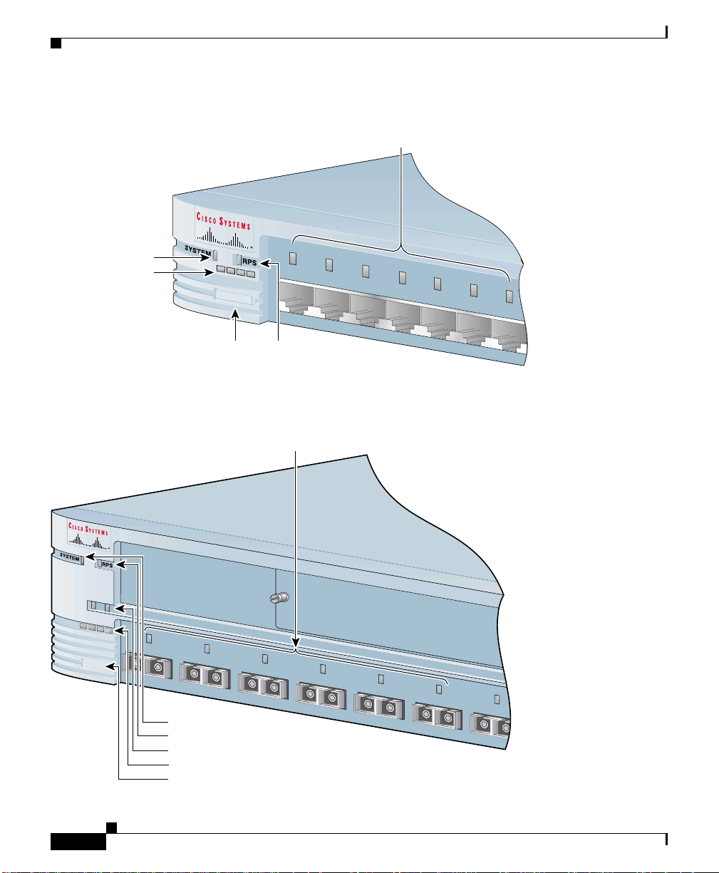
You can use the switch LEDs to monitor switch activity and its performance.
Figure 1-5, Figure 1-6,andFigure 1-7 show the location of the LEDs and the
Mode button that you use to select a po rt m ode . Changing a por t m ode changes
the information provided by eac h p ort LED.
All of the LEDs descri bed in this sec tio n except the util izat ion meter (U TL) are
visible on the C lust er M ana gement Suite (CMS) wind ow and, if the switch i s a
cluster member,on the CMS Cluster Manager window. The Catalyst 2900 Series
XL and Catalyst 3500 Series XL Software Configuration Guide de scri bes how to
use CMS to manage standalo ne or individual switch es and how to use cluster
management software to manage s witc h c luste rs].
Catalyst 2900SeriesXL Hardware Installation Guide
1-9
Page 30
100BASE-FX Ports
10
0B
A
S
E
-F
X
7
6
5
4
3
2
1
1
2
M
O
D
E
Figure 1-5 Catalyst 2912 XL, 2924 XL, and 2924C XL LEDs
10/100 port LEDs
Chapter1 Product Overview
System LED
1X 2X 3X
Port mode LEDs
M
O
D
E
Mode
button
1X 2X 3X
RPS
LED
Figure 1-6 Catalyst 2912MF XL and 2924M XL LEDs
10BASE-FX port LEDs
4X
4X
5X
5X
6X
6X
7X
7X
47288
1-10
System LED
RPS LED
Expansion slot status LED
Port mode LED
Mode button
Catalyst 2900 SeriesXL Hardware Installation Guide
48003
78-6461-03
Page 31

Chapter 1 Product Overview
Figure 1-7 Catalyst 2912 LRE XL and 2924 LRE XL LEDs
10/100 port LEDs
SYSTEM
MODE
Mode
button
SPEED
DUPLX
RPS
LRE
STAT
1X
2X
System LED
RPS LED
LRE LED
STAT LED
DUPLEX LED
Speed LED
3X
4X
LRE port LEDs 1-12
100BASE-FX Ports
48002
LRE port LEDs 13-24
System LED
78-6461-03
The system LED shows whether the system is receiving power and functioning
properly. Table 1-2 lists the LED colors and their meanings.
Table 1-2 System LED
Color System Status
Off System is not powered up.
Green System is operating normally.
Amber System is receivingpower but is not functioningproperly.
For information on the System L ED colors during P OST, see the “Powering On
the Switch and Running POST” sectiononpage2-25.
Catalyst 2900SeriesXL Hardware Installation Guide
1-11
Page 32

Chapter1 Product Overview
100BASE-FX Ports
RPS LED
TheCatalyst 2912 LRE XL, Catalyst 2924 LRE XL, andCatalyst 3524-PWR XL
switches use the Cisco RPS 300 (model PWR300-AC-RPS-N1). All other
Catalyst 2900 XL and Catalyst 3500 XL switches use the Cisco RPS 600
(model PWR600-AC-RPS). Re fer to the appropria te switch documentat ion for
redundant power system (RPS) descriptions specific for th e switch. Table 1-3 and
Table 1-4 list the RPS LED colors and their meanings.
Table 1-3 RPS LED on the Catalyst 2912 XL, 2924C XL, 2924 XL, 2924MF XL, and 2924M XL
Switches
Color RPS Status
Off RPSisofforisnotinstalled.
Green RPS is operational .
Blinking gree n The RPS and t he sw itch AC power supply are both powered up. If the switch power
supply fails, the switch powers down and after 15 seconds restarts, using power
from the RPS. The switch goes through its norma l boo t sequence when i t re starts.
Note This is not a recommended configuration.Formoreinformationseethe
“Cisco RPS Connector” sectiononpage1-19.
Amber RPS is connec ted but n ot functioning.
• The RPS c ould be in standby mode. Pressing t he Mode button on the RPS puts
it in Read y m ode, and the L ED should turn g re en.
• One of the power supplies in t he R PS could have failed.
• The fan in the RPS might have fail ed.
Table 1-4 RPS LED on the Catalyst 2912 LRE XL and 2924 LRE XL Switches
Color RPS Status
Off RPS is off o r is not installed.
Solid green RPS is connect ed and operational.
Blinking green RPS is backing up another switch in the stack.
Catalyst 2900 SeriesXL Hardware Installation Guide
1-12
78-6461-03
Page 33

Chapter 1 Product Overview
100BASE-FX Ports
Table 1-4 RPS LED on the Catalyst 2912 LRE XL and 2924 LRE XL Switches (continued)
Color RPS Status
Solid amber RPS is connected but not functioning properly.
• The RPS could be in standby mode. Pressing the Standby/Active button the
RPS puts it in Active mode, and the LED shou ld t urn green.
• One of the power su pplie s in the RPS could be powered down.
• A fan in the RPS might have failed.
Blinking ambe r Internal power supply of the switch is down, and redunda ncy is lost. Th e switch is
operating on the RPS.
Port LEDs and Modes
Each of the 10/100, 100BASE-FX, and LRE ports a nd module slots have a p ort
LED. These port LEDs, as a group or ind ividually, display information a bout the
switch and about the individual ports. The port modes (Table 1-5 and Table 1-6)
determine the type of information displayed.
To s elect or change a mode, press the Mode button until the desired mode is
highlighted. Whe n you change port modes, th e me ani ng of the port LED colors
also changes. Table 1-7and Table 1-8 list the p ort LED colors.
Table 1-5 Port Mode LEDs on the Catalyst 2912 XL, 2924C XL, 2924 XL, 2924MF XL, and 2924M XL
Switches
Mode LED Port Mode Description
STAT Port status The port status. This is the default mode.
UTL Switch utilization The current bandwidth in use by the switch. (See Figure 1-7.)
FDUP Port duplex mode The port dup lex mo de: full duplex or half duplex.
100 Port speed The port operating spe ed: 10, 100, or 1000 Mbps.
Catalyst 2900SeriesXL Hardware Installation Guide
78-6461-03
1-13
Page 34

Chapter1 Product Overview
100BASE-FX Ports
Table 1-6 Meanings of Port Status LED Colors for Different Modes on Catalyst 2912 LRE XL and
2924 LRE XL Switches
Mode LED Port Mode Description
LRE LRE link status Long-Reach Ethernet (LRE) link status of the LRE ports on the
Catalyst 2912 LRE XL and Catalyst 2924 LRE XL switches.
Default mode on these switches only.
Note When the LRE mode is active, the 10/100 switch
ports on the Catalyst 2912 LRE XL and
Catalyst 2924 LRE XL continue to show Ethernet
link s tatus.
STAT Port status Ethernet lin k s tatus of the 10/100 , 1 00BASE-FX, or
1000BASE-FX switch ports or the Ethernet link status on the
remote CPE.
Default mode on all Catalyst 2900 XL and Catalyst 3500 XL
switches except the Catalyst 2912 LRE XL and
Catalyst 2924 LRE XL switches.
DUPLX Port duplex mode Th e port duplex mode: full duplex or ha lf duplex.
SPEED Port speed The port operating speed: 1 0 o r 100 Mbps.
1-14
Catalyst 2900 SeriesXL Hardware Installation Guide
78-6461-03
Page 35

Chapter 1 Product Overview
100BASE-FX Ports
Table 1-7 Meanings of Port Status LED Colors for Different Modes on Catalyst 2912 XL, 2924C XL,
2924 XL, 2924MF XL, and 2924M XL Switches
Port Mode Port LED Color Meaning
STAT
(port status)
UTL
(utilization)
Off No link.
Solid green Link present.
Flashing green Activity. Port is transmitting or receiving data.
Alternating
green-amber
Link fault. Error frames can affect conn ectivity, and e rro rs such as
excessive collisions, CRC errors, and alignment and jabber errors
are monitored for a link-fault indication.
Solid amber Port is no t forwarding. Port was disabled by m anagem ent or an
address vi ola tion or was blocked by Spanning Tree Protoc ol (STP).
Note After a port is r econfigured, the port LED can remain
amber for up t o 30 seconds as ST P c hec ks the switch for
possible loops.
Green The LEDs display backplane utilization on a logarithmic scale.
If all port LEDs are gree n, the switch is using 50 perce nt o r more
of its total bandwi dth capacity. If the right-most LED is amber, the
switch is usin g le ss than 50 per cent of its total bandwidth. I f the
LED to the left of t he right-m ost LED is amber, the switch is using
less than 25 percent of its total capacity, and so on.
FDUP
(port duplex)
100
(port speed)
78-6461-03
See Figure 1-7 for details.
Off Port is oper ating in half d uplex.
Green Port i s op erati ng in full duplex.
Off Portisoperatingat10Mbps.
Green Port is operating at 100 Mbps.
Catalyst 2900SeriesXL Hardware Installation Guide
1-15
Page 36

Chapter1 Product Overview
100BASE-FX Ports
Table 1-8 Meanings of Port Status LED Colors for Different Modes on Catalyst 2912 LRE XL and
2924 LRE XL Switches
Port Mode Port LED Color Meaning
LRE Off No LRE link pr esent on the LRE port.
Green LRE link present on the LRE port. Port LED turns green within
10 seconds after the LRE port detects a connection to a
Cisco 575 LRE CPE.
Amber LRE port and WAN CPE port unable to establish the ra te defined
by the assigned profile.The switch has detected a CPE, but has not
established an LRE link at the configured profile.
Note The LED can be amber for a short period of time while
an LRE link is being established. However, if the LED
remains amber,there is a p roblem with the link between
the switch and the CPE.
STAT
(port status)
Off No link.
Solid green Li nk is present b etw een LRE port a nd a CPE WAN port and also
between the CPE Ethernet port and the remote Ethernet device.
Flashing green Activity. Port is transmitting or receiving data.
Alternating
green-amber
Link fault. Error frames can affect conn ectivity, and e rro rs such as
excessive collisions, CRC errors, and alignment and jabber errors
are monitored for a link-fault indication.
Solid amber Port is no t forwarding. Port was disabled by m anagem ent or an
address vi ola tion or was blocked by Spanning Tree Protoc ol (STP).
Note After a port is r econfigured, the port LED can remain
amber for up t o 30 seconds as ST P c hec ks the switch for
possible loops.
DUPLX Off Port is operating in half duplex.
Green Port i s op erati ng in full duplex.
SPEED Off Portisoperatingat10Mbps.
Green Port is operating at 100 Mbps.
Figure 1-7 shows bandwidth utilization percentages displayed by the right-most
LEDs.
Catalyst 2900 SeriesXL Hardware Installation Guide
1-16
78-6461-03
Page 37

Chapter 1 Product Overview
Figure 1-8 Bandwidth Utilization
100BASE-FX Ports
SYSTEM RPS
MODE
1x 2x 3x 4x 5x 6x 7x 8x
10BaseT/100BaseTx
6.25–12.4%+
12.5–24%+
25–49%+
50%+
Expansion Slot LEDs
Expansion slot LEDs ( shown in Figure 1-6) show the stat us of installed modules.
The LE Ds are numbered 1 (left s lo t) and 2 ( righ t slot). Table 1-9 lists LED colors
and their meanings.
Table 1-9 Expansion Slot LEDs
Color Expansion Slot Status
Off No module is installed.
Green Module is ope rati ng normally.
Amber Module failed POST and should be r ep laced .
9x
10x 11x 12x
Catalyst 2900
SER
XL
S
IE
47293
78-6461-03
Catalyst 2900SeriesXL Hardware Installation Guide
1-17
Page 38

Rear-Panel Descripti on
Rear-Panel Description
The switch rear panels have an AC power connector, an RPS connector, and an
RJ-45 console p ort (see Figure 1-1 0, Figure 1-10,andFigure 1-11), which are
described in this section.
Figure 1-9 Catalyst 2912 XL, 2924 XL, and 2924C XL Rear Panel
Fans
D
C
I
N
P
U
T
S
F
O
R
P
O
W
E
R
S
P
E
C
I
F
I
E
D
+
5
V
@
9
A
,
R
E
M
O
T
E
S
U
P
P
L
Y
I
N
M
A
N
U
A
L
+
1
2
V
@
0
.
5
A
RJ-45
connector
C
O
N
S
O
L
E
AC power
connector
R
A
T
I
N
G
1
0
0
-
1
2
7
/
2
0
0
-
2
4
0
1
~
V
.
0
A
/
O
.
5
A
5
0
-
8
0
H
Z
Redundant
power system
connector
Chapter1 Product Overview
47295
Figure 1-10 Catalyst 2924M XL and Catalyst 2912MF XL Rear Panel
Fans
CONSOLE
RJ-45
D
C
I
N
P
U
T
S
F
O
R
R
E
P
M
O
O
W
T
E
E
R
S
U
P
S
P
P
L
E
Y
C
I
F
I
E
D
I
+
N
5
V
M
A
N
U
@
A
L
9
A
,
+
1
2
V
@
0
.
5
A
DC INPUT
R
A
T
I
N
G
1
0
0
-
1
2
0
/
2
0
0
~
-
2
4
0
2
V
.
0
A
/
1
.
0
A
5
0
-
6
0
H
Z
connector
Redundant
power system
connector
Catalyst 2900 SeriesXL Hardware Installation Guide
AC power
connector
1-18
47296
78-6461-03
Page 39

Chapter 1 Product Overview
Figure 1-11 Catalyst 2912 LRE XL and 2924 LRE XL Rear Panel
1
0
0
-
2
4
0
V
~
M
5
A
-
X
3
A
IM
U
M
3
0
0
W
5
0
T
/6
O
0
T
H
A
z
L
O
U
T
P
U
T
D
C
O
U
T
P
U
T
C
O
N
S
O
L
AC power
connector
Redundant
power system
connector
E
RJ-45
connector
Power Connectors
You can provide power to the switch either through the internal power supply or
through the Cisco RPS.
Rear-Panel Description
48004
Internal Power Supply Connector
The internal power supply is a n au tora nging unit that sup por ts input voltages
between 100 a nd 240 VAC. If you plan to use the internal power supply, use the
supplied AC power cord to connect the AC power connector to an AC power
outlet.
Cisco RPS Connector
Specific Cisco RPS m odels support specific Catalyst 2900 XL switches:
• Cisco R PS 600 (model PWR600- AC-RPS)—support s the Catalyst 291 2 XL,
2924C XL, 2924 XL, 2924MF XL, and 2924M XL switches
• Cisco RPS 300 (mo del PWR300-AC-RPS-N1)—supports the Catalyst
2912LREXLand2924LREXLswitches
78-6461-03
Catalyst 2900SeriesXL Hardware Installation Guide
1-19
Page 40

Chapter1 Product Overview
Rear-Panel Descripti on
RPS Connector on the Catal yst 2912 XL, 2924C XL, 2924 XL, 2924MF XL, and 2924M XL Switches
The Cisco RPS 600 (mo del PWR600-AC-RPS) provides a quasi-redundant power
source for four external devices that use up to 1 50W DC each. Us e a one-to-one
cable (one connector at each cable end) to connect four external devices to the
four DC output power modules. T he power source is quasi-redundant be cause
there are two AC input power modules for t he C isco RPS and one DC output
power module for each external d evice. Th e AC input to the Cis co RPS is fully
redundant, but the DC output t o the external devices is not.
Warning
Note Do not connect the switch power cord to an AC outlet if the switch is also
Attach only the Cisco RPS (model PWR600-AC-RPS) to the RPS 600
receptacle.
connected to a powered-on RPS. The switches do not support the
fully-redundant c on figuration described in the RPS docum entat ion . The
redundant-with-r eboot configuration i s n ot recommended.
For more inf orma tion on the Cisco RPS 600 , refer to the Cisco Redunda nt Power
System Hardware Installation Guide.
RPS Connector on the Catal yst 2912 LRE and 2924 LRE XL Switches
The RPS is a 300W redundant p ower sys tem that ca n support six external network
devices an d provides power to o ne failed device at a time. It a utom ati call y senses
when the power supply of a connected device fails and provid es the necessary
power to the faile d device to prevent loss of network traffic. W hen the device
internal power supply has been bro ught up or replaced, the RPS autom atica lly
stops powering the d evice.
Warning
Attach only the Cisco RPS (model PWR300-AC-RPS-N1) to the RPS 300
receptacle.
1-20
Catalyst 2900 SeriesXL Hardware Installation Guide
78-6461-03
Page 41

Chapter 1 Product Overview
Note The RPS can only power one switch at a time. If more than one switch fails at
Console Port
Rear-Panel Description
the same time, any subsequent switch is not supported by the RPS un til the
first switch failure is resolved.
For more inf orma tion on the Cisco RPS 300 , refer to the Cisco Redunda nt Power
System 300 H ardware Installation Guide.
YoucanconnectaswitchtoaPCthroughtheswitchconsoleportandbyusing
the supplied rollover cable and DB-9 adapter. You need to provide a
RJ-45-to-DB-25 female DTE a dapter to connect the switch c onsol e port to a
terminal. Yo u c an order a kit (part number ACS-DSBUASYN=) containing that
adapter from Cisco. For conso le port and ad ap ter pinout informa tion, see the
“Connecti ng to the Console Port” section on page 2-33.
78-6461-03
Catalyst 2900SeriesXL Hardware Installation Guide
1-21
Page 42

Rear-Panel Descripti on
Chapter1 Product Overview
1-22
Catalyst 2900 SeriesXL Hardware Installation Guide
78-6461-03
Page 43

CHAPTER
Installation
This chapter describes how to install your Catalyst 2900 XL switch and interpret
the power-on self-test (POST) that ensures proper operation. Read the topics and
perform these procedures i n th e order that they are present ed:
• Pre-installation information and guidelines
• Installation procedures
• Power-on pro cedures
• Connection procedures
• Where to go n ext
Note See the Catalyst 2900 Series XL Modules Installation Guide and the
Catalyst 2900 Seri es X L ATM Modules Inst allation and Configuration Guide
for global inf ormati on about the Cat alyst 2900 series XL expansion module s.
2
Preparing for Installation
Warnings
These warning s ar e tr an sl at e d int o several la ng u ag es i n Appendix C, “Translated
Safety Warnings.”
78-6461-03
Catalyst 2900SeriesXL Hardware Installation Guide
2-1
Page 44

Preparing for Instal la t io n
Chapter2 Installation
Warning
Warning
Warning
Warning
Warning
Only trained and qualified personnel should be allowed to install or replace
this equipment.
Read the installation instructions before you connect the system to its
power source.
Before working on equipment that is connected to power lines, remove
jewelry (including rings, necklaces, and watches). Metal objects will heat
up when connected to power and ground and can cause serious burns or
weld the metal object to the terminals.
Do not stack the chassis on any other equipment. If the chassis falls , it can
cause severe bodily injury and equipment damage.
The plug-socket combination must be accessible at all times because it
serves as the main disconnecting device.
2-2
Warning
To prevent the switch from overheating, do not operate it in an area that
exceeds the maximum recommended ambient temperature of 113×F (45×C) .
To prevent airflow restriction, allow at least 3 inches (7.6 cm) of clearance
around the ventilation openings.
Warning
Warning
The device is designed to work with TN power systems.
When installing the unit, the ground connection must always be made first
and disconnected last.
Catalyst 2900 SeriesXL Hardware Installation Guide
78-6461-03
Page 45

Chapter 2 Insta llation
Preparing for Installation
Warning
Warning
Warning
Warning
Warning
This product relies on the building’s installation for short-circuit
(overcurrent) protection. Ensure that a fuse or circuit breaker no larger than
120 VAC, 15A U.S. (240 VAC, 10A international) is used on the phase
conductors (all current-carrying conductors).
This equipment is intended to be grounded. Ensure that the host is
connected to earth ground during normal use.
Care must be given to connecting units to the supply circuit so that wiring is
not overloaded.
A voltage mismatch can cause equipment damage and may pose a fire
hazard. If the voltage indicated on the label is different from the power
outlet voltage, do not connect the chassis to that receptacle.
Do not touch the power supply when the power cord is connected. For
systems with a power switch, line voltages are present wi thi n the power
supply even when the power switch is off and the power cord is connected.
For systems without a power switch, line voltages are present within the
power supply when the power cord is connected.
78-6461-03
Warning
Warning
Do not work on the system or connect or disconnect cables during periods
of lightning activity.
Ultimate disposal of this product should be handled according to all national
laws and regulations.
Catalyst 2900SeriesXL Hardware Installation Guide
2-3
Page 46

Preparing for Instal la t io n
Chapter2 Installation
Warning
Warning
Warning
Warning
Invisible laser radiation may be emitted from the aperture ports of the
100BASE-FX single-mode supervisor engine module. Avoid exposure and do
not stare into open apertures.
Avoid exposure to the laser beam.
Attach only the Cisco RPS (model PWR600-AC-RPS) to the RPS receptacle.
Attach only the Cisco RPS (model PWR300-AC-RPS-N1) to the RPS
receptacle.
EMC Regulatory Statements
U.S.A.
U.S. regulatory i nfor matio n for this pro duct is in the f ron t matter of th is manual.
Taiwan
2-4
15456
Catalyst 2900 SeriesXL Hardware Installation Guide
78-6461-03
Page 47

Chapter 2 Insta llation
Hungary
This equipment i s a class A product and should be used and installed properly
according to the Hungarian EMC Class A requirements (MSZEN55022). Class A
equipment is designed for typical commercial establishments for which special conditions of installation and protection distance are used.
Figyelmeztetés a felhasználóikézikönyv számára:
Ez a berendezés “A” osztályú termék, felhasználására és üzembe helyezéséreamagyar EMC “A” osztályú követelményeknek (MSZ EN 55022) meg
sor, illetve ezen “A” osztályú berendezések csak megfelelo kereskedelmi forrásból
származhatnak, amelyek biztosítják a megfelelo speciális üzembe helyezési
körülményeket és biztonságos üzemelési távolságok alkalmazását.
Installation Guidelines
The switch can be installed on a table or shelf, in a rack, or on a wall.
Preparing for Installation
feleloen kerülhet
78-6461-03
Before installing the switch, first verifythat the switch is operational by powering
it on and ru nning POST. Follow th e procedures in the “Powering On the Switch
andRunningPOST” section on p age 2-25.
Caution There are no serviceable parts inside the unit. Removing screws, cover, or
otherwise disman tlin g t he unit voids the warr anty.
Warning
Unplug the power cord before you work on a system that does not have an
on/off switch.
When determining where to place the switch, be sure to observe these guidelines:
• For 10/100 ports, cable lengths from the swit ch t o connected devices are up
to 328 feet (100 meters).
• For 100BASE-FX ports, cable lengths from the switch to connected devices
are up to 1351 feet ( 412 meters) for half-duplex conne ctions and less than
6561 feet (2 kilometers) for full-duplex connections.
Catalyst 2900SeriesXL Hardware Installation Guide
2-5
Page 48

Preparing for Instal la t io n
Chapter2 Installation
• For LRE ports, cable lengths from the swit ch to the connec ted Ethernet
device are up to 4921 feet (1500 meters) .
• Cabling is away from sources of electrical noise, such as radios, power lines,
and fluorescent ligh ting fixtures.
• For specifications of the expansion m odul es, r efer to the modu les
documentation in the “Related Publications” section on p age xvi.
• Clearance t o front and r ea r panels meet these con dit ion s:
–
Front-panel ind icat ors can be easi ly read.
–
Access to ports is sufficient for unrestricted cabling.
–
Rear-panel power connector i s within r eac h of an AC power re c ept ac le.
• Operating environment is within the ranges listed in Appendix A, “Technical
Specifications.”
• Airflow around the switch and throug h the vents is unrest ricte d.
• Temperature around the unit does not exceed 113°F(45°C).
Note If the switch is installed in a closed or multirack assembly, the
temperature aro und it might be greater than normal room
temperature.
Verifying Package Contents
When you unpack the switch, be sure that the package contains the items in the
following list. If any items are missing, notify your authorized Cisco sales
representative:
• The switch
• Catalyst 2900 XL and Catalyst 3500 XL Documentation CD
• Release Notes for the Cataly st 29 00 Series XL and Catalyst 3500 Series XL
Cisco IOS Release 12.0(5)WC(1)
• The Cisco D oc ume ntat ion CD-ROM package
• AC power c ord
Catalyst 2900 SeriesXL Hardware Installation Guide
2-6
78-6461-03
Page 49

Chapter 2 Insta llation
Installing the Switch on a Table or Shelf
• Mounting kit containing these items:
–
Four rubber feet for mounting the switch on a table, shelf , or desk
–
Two mounting brackets
–
Four number-12 Phillips machine screws for attaching the brackets to a
rack
–
Four number-8 Phillips flat-head screws for attaching the brackets to the
switch (19-inch rack mount)
–
Four number-8 Phillips truss-head screws for attaching th e brackets to
the switch (24-inch rack mount)
–
One cable guide and one (two for mod ul ar switches) bl ack Phillips
machine screw for attaching the cable guide to one of the mounting
brackets
Note The cable guide is not applicable for the Catalyst 2912 LRE XL
and 2924 LRE XL switches.
• One RJ-45-to-R J-45 rollover cable
• One RJ-45-to-DB-9 adapter
• Cisco Information Packet, containing warranty, safety, and suppor t
information
Installing the Switch on a Table or Shelf
Follow these steps to install the switch on a table or shelf:
Step 1 Locate the adhesive strip with the rubber feet in the mounting-kit envelope.
Attach the four rubber fee t to the recessed areas on the bottom of the unit.
Step 2 Place the swit ch on the table or shelf near an AC power source.
Step 3 After the swit ch is mounted on the table or shelf, power the switch as desc rib ed
in “Powering On the Switch and Running POST” sectiononpage2-25.
Catalyst 2900SeriesXL Hardware Installation Guide
78-6461-03
2-7
Page 50

Installing the Switch in a Rack
Installing the Switch in a Rack
Chapter2 Installation
Warning
To prevent bodily injury when mounting or servicing this unit in a rack, you
must take special precautions to ensure that the system remains stable. The
following guidelines are provided to ensure your safety:
• This unit should be mounted at the bo ttom of the rack if it is t he o nly uni t in
the rack.
• When mounting this unit in a partially filled rack, load the rack from the
bottom to the top with th e heaviest component at the bottom of the rack .
• If the rack is provided with stabilizing devices, install the stabilizers before
mounting or servicing the unit in the rack.
The supplied rack-mounting b rackets can be attac hed to a 19-, 23-, or 24-inc h
rack. Figure 2-1 shows which mou nting holes to use.
Note Figure 2-1 shows bra ckets for two-rack-u nit modular switche s. Rack-mount
points are similar on brackets for one-rack-unit switches.
2-8
Catalyst 2900 SeriesXL Hardware Installation Guide
78-6461-03
Page 51

Chapter 2 Insta llation
Installing the Switch in a Rack
Figure 2-1 Mounting Bracket Points for Catalyst 2912 XL, 2924C XL, 2924 XL,
2912MF XL, or 2924M XL Switches
19" rack
mount point
19" rack
mount point
24" rack
mount point
24" rack
mount point
23" rack
mount point
23" rack
mount point
Figure 2-2 Mounting Brackets Points for Catalyst 2912 LRE XL and
2924 LRE XL Switches
19" rack
mount point
24" rack
mount point
23" rack
mount point
47307
78-6461-03
19" rack
mount point
24" rack
mount point
Catalyst 2900SeriesXL Hardware Installation Guide
23" rack
mount point
54725
2-9
Page 52

Installing the Switch in a Rack
To install the switch in a 19-, 23- or 24-inch standard rack, follow the instructions
described in t hese procedures:
• “Removing Screws from the Switch” sectiononpage2-10
• “AttachingtheBrackets to a Catalyst 2912 XL, 2 924C XL, 2924 XL, 2912MF
XL, or 2924M XL Switch” section on page 2-11
• “Attaching the Brackets to a Catalyst 2912 LRE XL or 2924 LRE XL Switch”
sectiononpage2-17
• “Mounting the Switch in a Rack” sectiononpage2-19
• “Attaching the Optional Cable Guide” sectiononpage2-20
Removing Screws from the Switch
Ifyouplantoinstalltheswitchinarack,youmustfirstremovescrewsinthe
switch chassis so that mounting brackets can be attached. Figure 2- 3 shows how
to remove the chassis screws in a fixed-port and a modular port switch.
Chapter2 Installation
2-10
Figure 2-3 Removing Screws from the Switch
C
a
ta
ly
s
t 2
9
0
0
S
E
R
I
E
X
S
L
C
a
t
a
ly
s
t 2
9
0
0
S
E
R
IE
X
S
L
22X22X
2
3X
2
4X
Catalyst 2900 SeriesXL Hardware Installation Guide
Fixed-port
Catalyst 2900 series XL
Modular
Catalyst 2900 series XL
47292
78-6461-03
Page 53

Chapter 2 Insta llation
Installing the Switch in a Rack
Attaching the Brackets to a Catalyst 2912 XL, 2924C XL, 2924 XL, 2912MF XL, or 2924M XL Switch
Follow these steps to attach the brackets to a Catalyst 2 912 XL, 2924C XL, 2924
XL, 2912MF XL, or 2924M XL switch:
The bracket orientation and screws that you use depend on whether you are
attaching th e brackets for a 19-, 23-, or 24-inch rac k. Use two of t he supplied
screws to attach each bracket, according to rack size:
• For a 19-inch rack, use the supplied Ph illips flat-head screws to attach the
long side of the bracket to the switch.
• Fora23- or 24-inchrack,usethesuppliedPhillipstruss-headscrews to attach
the short side of the bracket to the switch.
Figure 2-3, Figure 2-5, Figure 2-6, Figure 2-7,andFigure 2-8 show how to attach
a bracket to one side of the switch. Follow the s ame steps to attach the s econd
bracket to the opposite side of the switch.
78-6461-03
Catalyst 2900SeriesXL Hardware Installation Guide
2-11
Page 54

Chapter2 Installation
Installing the Switch in a Rack
Figure 2-4 Attaching Brackets on Catalyst 2912 XL, 2924C XL, 2924 XL Fixed-Port Switches
(Front-Panel Forward)
Phillips
flat-head
screws
1X 2X 3X
Phillips
truss-head
screws
19" configuration
23" and 24" configuration
1X 2X 3X
M
O
D
E
4X
4X
5X
5X
6X
6X
7X
7X
1X 2X 3X
1X 2X 3X
M
O
D
E
4X
4X
5X
5X
6X
6X
47738
7X
7X
2-12
Catalyst 2900 SeriesXL Hardware Installation Guide
78-6461-03
Page 55

Chapter 2 Insta llation
Installing the Switch in a Rack
Figure 2-5 Attaching Brackets on Catalyst 2912MF XL an d 29 24 M XL M odu lar
Switches (Front-Panel Forward)
Phillips
flat-head
screws
1
2
1X 2X 3X
1X 2X 3X
4X
4X
5X
5X
6X
6X
7X
7X
1
2
1X 2X
1X 2X
3X
3X
4X
M
O
D
E
4X
5X
5X
6X
6X
7X
7X
47297
Phillips
truss-head
screws
M
O
19" configuration
D
23" and 24" configuration
E
78-6461-03
Catalyst 2900SeriesXL Hardware Installation Guide
2-13
Page 56

Installing the Switch in a Rack
Figure 2-6 Attaching Brackets on Catalyst 2912 XL, 2924C XL, 2924 XL
Chapter2 Installation
Fixed-Port Switches (Rear-Panel Forward)
Phillips
flat-head
screws
19" configuration
Phillips
truss-head
screws
23" and 24" configuration
47298
2-14
Catalyst 2900 SeriesXL Hardware Installation Guide
78-6461-03
Page 57

Chapter 2 Insta llation
Installing the Switch in a Rack
Figure 2-7 Attaching Brackets on Catalyst 2912MF XL an d 29 24 M XL M odu lar
Switches (Rear-Panel F or ward)
Phillips
flat-head
screws
Phillips
truss-head
screws
DC INPUT
DC INPUT
R
A
T
I
N
G
1
0
0
-
1
2
0
/
2
0
0
~
-
2
4
0
2
V
.
0
A
/
1
.
0
A
5
0
-
6
0
H
Z
19" configuration
R
A
T
I
N
G
1
0
0
-
1
2
0
/
2
0
0
~
-
2
4
0
2
V
.
0
A
/
1
.
0
A
5
0
-
6
0
H
Z
78-6461-03
23" and 24" configuration
Catalyst 2900SeriesXL Hardware Installation Guide
47299
2-15
Page 58

Installing the Switch in a Rack
Figure 2-8 Attaching Brackets for Te lco Racks
Note Catalyst 2912 LRE XL and 2924 LRE XL switches can not be mounted in telco
racks.
DC INPUT
Chapter2 Installation
Phillips
flat-head
screws
R
A
T
IN
G
1
0
0
-
1
2
0
/
2
0
0
~
-
2
4
0
2
V
.0
A
/
1
.
0
A
5
0
-
6
0
H
Z
Phillips
flat-head
screws
52532
2-16
Catalyst 2900 SeriesXL Hardware Installation Guide
78-6461-03
Page 59

Chapter 2 Insta llation
Installing the Switch in a Rack
Attaching the Brackets to a Catalyst 2912 LRE XL or 2924 LRE XL Switch
Follow these steps to attach the brackets to a Catalyst 2912 LRE XL or
2924 LRE XL sw itch:
The bracket orientation and screws that you use depend on whether you are
attaching th e brackets for a 19-, 23-, or 24-inch rac k. Use two of t he supplied
screws to attach each bracket, according to rack size:
• For a 19-inch rack, use the supplied Ph illips flat-head screws to attach the
long side of the bracket to the switch.
• Fora23- or 24-inchrack,usethesuppliedPhillipstruss-headscrews to attach
the short side of the bracket to the switch.
Figure 2-3, Figure 2-5, Figure 2-6, Figure 2-7,andFigure 2-8 show how to attach
a bracket to one side of the switch. Follow the s ame steps to attach the s econd
bracket to the opposite side of the switch.
78-6461-03
Catalyst 2900SeriesXL Hardware Installation Guide
2-17
Page 60

Chapter2 Installation
Installing the Switch in a Rack
Figure 2-9 Attaching Brackets on Catalyst 2912 LRE XL and 2924 LRE XL Switches (Front-Panel
Forward)
Phillips
flat-head
screws
INPUT PWR
Phillips
truss-head
screws
19" configuration
23" and 24" configuration
OUTPUT PWR
RESET
OUTPUT PWR
RESET
INPUT PWR
TEMP
TEMP
FAN
FAN
9X
10X
11X
12X
9X
10X
11X
12X
2-18
54728
Catalyst 2900 SeriesXL Hardware Installation Guide
78-6461-03
Page 61

Chapter 2 Insta llation
Installing the Switch in a Rack
Figure 2-10 Attaching Brackets on Catalyst 2912 LRE XL and 2924 LRE XL Switches (Rear-Panel
Forward
Phillips
flat-head
screws
19" configuration
23" and 24" configuration
Mounting the Switch in a Rack
After the brac kets are attached to the switch, use the four supplied number-12
Phillips machine screws to securely attach the brackets to the rack, as shown in
Figure 2-11.
78-6461-03
Phillips
truss-head
screws
54824
Catalyst 2900SeriesXL Hardware Installation Guide
2-19
Page 62

Installing the Switch in a Rack
Figure 2-11 Mounting the Switch in a Rack
1
X
2
X
3
X
4
MODE
X
5X
6
X
7
X
8
X9
X
1
1
0
0
B
B
a
a
s
s
e
e
1
T
T
0
/1
/1
0
B
0
0
0
0
a
B
B
s
a
a
e
s
s
F
e
e
X
T
T
X
X
1
0
X
1
1
X
12
X
13
X
14
X
Phillips machine
screws
1
2
1X 2X 3X
1X 2X 3X
4X
MODE
4X
5X
5X
6X
6X
7X
7X
8X
8X
1
0
0
B
a
s
9X
9X
e
F
10X
10X
X
11X
11X
12X
12X
13X
13X
14X
14X
15X
15X
Chapter2 Installation
1
6
X
1
7
X
18
X
1
16X
16X
17X
17X
18X
18X
19X
19X
Catalyst 2900
9
X
2
0
X
2
1
X
20X
20X
21X
21X
S
E
R
IE
X
S
2
3
X
C
atalyst 2900
23X
L
2
4
X
SERIES
X
L
24X
47301
2
2
X
22X
22X
Phillips machine
screws
After the switc h is mounted in the rack, power th e switch as descri bed in
“Powering On the Switch and Running POST” sectiononpage2-25.
Attaching the Optional Cable Guide
We recommend attaching the cable guide to preventthecablesfromobscuring the
front panel of the switch and the other devices installed in the rac k. If th e sw itch
is in a 19-, 23-, or 24-inch rack, use the s upplied black screw as shown in
Figure 2-12 to attach the cable guide to the left or right bracket. The cable guide
for the modular switches requires two screws.
Catalyst 2900 SeriesXL Hardware Installation Guide
2-20
78-6461-03
Page 63

Chapter 2 Insta llation
Note The cable guide is not applicable for the Catalyst 2912 LRE XL and
2924 LRE XL switches.
Figure 2-12 Attaching the Cable Guide
1
X
2
X
3
X
4
M
O
D
E
Cable guide screw
X
5
X
6
X
7
X
8
X
9
X
1
0
X
1
1
X
Installing the Switch in a Rack
10B
10B
aseT/100B
aseT/100B
1
0
0
B
a
s
aseTX
aseTX
e
F
X
1
2
X
1
3
X
1
4
X
1
6
X
1
7
X
1
8
X
C
a
ta
ly
st 2
9
0
1
9
X
2
0
X
0
S
E
R
I
E
X
S
2
1
X
2
2
X
L
2
3
X
2
4
X
78-6461-03
1
2
1
1
X
X
2
2
X
X
3
3
X
X
4
4
X
M
O
D
E
X
5
5
X
X
6
6
X
X
7
7
X
X
8
8
X
X
9
9
X
X
1
1
0
0
X
X
Black Philips machine screw
Catalyst 2900
S
E
R
I
E
X
S
1
0
0
B
a
s
e
F
X
1
1
1
1
X
X
1
1
2
2
X
X
1
1
3
3
X
X
1
1
4
4
X
X
1
1
5
5
X
X
1
1
6
6
X
X
1
1
7
7
X
X
1
1
8
8
X
X
1
1
9
9
X
X
2
2
0
0
X
X
2
2
1
1
X
X
2
2
2
2
X
X
L
2
3
X
2
4
X
47302
Catalyst 2900SeriesXL Hardware Installation Guide
2-21
Page 64

Installing the Switch on a Wall
Installing the Switch on a Wall
To attach the switch to a wall, follow the procedures in this section:
• Attaching the brackets to the switch
• Attaching the switch to a wall
Note To mount a Cataly st 29 12 LRE XL or 2924 LRE XL swi tch on a
wall,youneedtoobtaintwospecialwall-mountbrackets(Ciscopart
number wallmount-1ru =) . To order these brackets, contact your
Cisco sales representative.
Attaching the Brackets to the Switch
The bracket orientation and the screws you use depend on whether you are
attaching the brackets for parallel or vertical wall-mounting. Use two of the
supplied screws to attach each bracket, according to the following guidelines:
Chapter2 Installation
2-22
• For parallel wall-mounting, use the supplied Phillips truss-head screws to
attach the s hort side of the bracket to the switch.
• For vertical wall-mounting, use the supplied Phillips flat-head screws to
attach the lo ng side of the bracket to the switch.
Note The Catalyst 291 2 LRE XL and 2924 LRE XL sw itch es cannot be mount ed
vertically on a wall.
Figure 2-13 an d Figure 2-13 show how t o at tach the brackets to one side of the
switch. Follow the same steps to attach the second bracket to the opposite side of
the switch.
Catalyst 2900 SeriesXL Hardware Installation Guide
78-6461-03
Page 65

Chapter 2 Insta llation
Installing the Switch on a Wall
Figure 2-13 Attaching Brackets for Parallel and Vertical Wall-Mounting for
Fixed-Port Switches
Phillips
truss-head
screws
Figure 2-14 Attaching Brackets for Parallel and Vertical Wall-Mounting for
Modular Switches
47303
R
A
T
I
N
G
1
0
0
-
1
2
0
/
2
0
0
~
-
2
4
0
2
V
.
0
A
/
1
.
0
A
5
0
-
6
0
H
DC INPUT
Z
Mounting the Switch to a Wall
For best support of the switch and cables, make sure the switch is attached
securely to a wall stud or to a firmly attached plywood mounting backboard, as
shown in Figure 2-15, Figure 2-16,andFigure 2-17.
78-6461-03
Phillips
truss-head
screws
Catalyst 2900SeriesXL Hardware Installation Guide
47304
2-23
Page 66

Installing the Switch on a Wall
Figure 2-15 Mounting a Fixe d-Port Switch to a Wall
Vertical
wall stud
S
IE
R
E
S
x
4
2
x
3
2
x
2
2
x
1
2
x
0
2
x
9
1
x
8
1
x
7
1
x
6
1
x
5
1
x
4
1
x
T
x
e
3
s
1
a
B
0
0
1
/
T
e
x
s
2
a
1
B
0
1
x
1
1
x
0
x1
9
x
8
x
7
x
6
x
5
x
4
x
3
x
x2
1
S
P
R
User-supplied
screws
E
D
O
M
Chapter2 Installation
47305
2-24
Catalyst 2900 SeriesXL Hardware Installation Guide
78-6461-03
Page 67

Chapter 2 Insta llation
Figure 2-16 Mounting a Modular Switch to a Wall
Vertical
wall stud
User-supplied
screws
S
IE
R
E
S
x
4
2
x
3
2
x
2
2
x
1
2
x
0
2
x
9
1
User-supplied
x
8
1
x
7
1
x
6
screws
1
x
5
1
x
4
1
X
T
e
x
s
3
a
1
B
0
0
1
/
T
e
s
x
a
2
1
B
0
1
x
1
1
x
0
1
x
9
x
8
x
7
x
x6
5
x
4
x
3
x
x2
1
E
D
O
M
Powering On the Switch and Running POST
S
IE
R
E
S
x
4
2
x
3
2
x
2
2
x
1
2
x
0
2
x
9
1
x
8
1
x
7
1
x
6
1
x
5
1
x
4
1
X
T
e
x
s
3
a
1
B
0
0
1
/
T
e
s
x
a
2
1
B
0
1
x
1
1
x
0
1
x
9
x
8
x
7
x
6
x
x5
4
x
3
x
2
x
1
E
D
O
M
Vertical wall-mount
Parallel wall-mount
47306
After the switch is mounted on the wall, power the switch as described in
“Powering On the Switch and Running POST” sectiononpage2-25.
Powering On the Switch and Running POST
To p ower on the switch after you install it, follow these steps:
Step 1 Connect one end of the AC power cord to th e AC power connector on the switch.
Step 2 Connect the other end of the power cord to an AC power outlet.
As the switch powers on, it begins POST,a series of eight tests that run
automatically to ensure that the switch f unctions properly. When the switch
begins POST, the por t LEDs turn a mber for 2 seconds, and then they turn green.
Catalyst 2900SeriesXL Hardware Installation Guide
78-6461-03
2-25
Page 68

Connecting to a 10/100 Port
The System LED flashes green, and the RPS LE D turns off. As each tes t runs, th e
port LEDs, starting with number 1 , tur n o ff. The port LEDs for po rts 2 to 8 each
turn off in turn as the system completes a test .
When POST compl etes successfully, the port LEDs re turn to the status mode
display, indicati ng that the switch is operational . If a test fails , the port LED
associated with the test turns amber, and the system LED turns amber. If POST
fails, refer to Chapter 3, “Troubleshooting,” t o determine a course of act ion.
POST failures are usually fatal. Call Cisco Sy stems immediately if your switch
does not pass PO ST.
Connecting to a 10/100 Port
The switch 10/100 ports configure themselves to operate at the speed of attached
devices. I f the attached ports do not support autonegotiation, you can explicitly
set the speed and duplex param eters.
Connecting devices that do not autonegotiate or that have their speed and duplex
parameters man ua lly set can red uce performance or result in no linkage. To
maximize perfor manc e, choose one of these methods f or configuring the 10 /100
Ethernet por ts:
Chapter2 Installation
2-26
• Let the por ts a utonegot iat e both speed and duplex.
• Set the port speed and duplex parameters on both end s o f t he connection.
Catalyst 2900 SeriesXL Hardware Installation Guide
78-6461-03
Page 69

Chapter 2 Insta llation
Step 1 When c onnec ting to workstations, servers, routers , and Cisco IP Phones, connec t
Connecting to a 10/100 Port
Follow t hese steps to conn ec t t o 10BASE-T and 100BASE-TX devices:
a straight-throu gh Category 5 cable to an RJ-45 connector on the front pane l
(Figure 2-17 ). When connecting to switches or repeaters, use a crossover
Category 5 cable. Pinouts for the cables are described in the “Cable and Adapter
Specifications” sectiononpageB-4.
Figure 2-17 Connecting to a 10/100 Switch Port
1X 2X 3X
1X 2X 3X
4X 5X 6X
M
O
D
E
4X 5X 6X
7X
7X
78-6461-03
47291
Note The switch ca n connect to a Cisco IP Pho ne through a stra ight-t hroug h,
twisted-pair ca ble. The rea r panel of the Cisco IP Phone might have mor e than
one RJ-45 jack . Use the LAN-to -phone jack to c onnec t the phone to the
switch. Refer to the documentation that came with y our Cisco IP Phone for
information about connectin g devices to it.
Step 2 Connect one e nd of the cable to the RJ-45 connector of the switch 10/ 100 port.
Step 3 Connect the other end of the cable to an RJ-45 con ne ctor of the othe r device.
The switch port LED come s on when both the switch and the connecte d d evice
have established link.
Catalyst 2900SeriesXL Hardware Installation Guide
2-27
Page 70

Connecting to a 100BASE-FX Po rt
The port LED is amber w hile Spanning Tree Protocol (STP) discovers the
topology and se arc hes for loops. This takes about 30 seconds, a nd then the port
LED turns gre e n.
If the port LED does not come on, the device at the other end might not be t urne d
on, or there might be a cable problem or a problem with the adapter installed in
the attached device. See Chapter 3, “Troubleshooting,” for solutions to cabling
problems.
Step 4 Reconfigure and r eboot the connect ed device if necessary.
Step 5 Repeat Steps 1 through 3 to connect to each 10/100 port.
Connecting to a 100BASE-FX Port
Chapter2 Installation
2-28
Warning
Warning
Caution Do not remove the rubber plugs from the fiber-optic port or the rubber caps
Invisible laser radiation may be emitted from the aperture ports of the
100BASE-FX single-mode supervisor engine module. Avoid exposure and do
not stare into open apertures.
Avoid exposure to the laser beam.
from the fiber-optic cable until you are ready to connect the c abl e. The plugs
and caps protect the fiber-optic port and cable from contamination a nd
ambient light.
You can connect the 10 0BASE-FX port s to other 100BASE-FX-compat ible
network devices, such as servers, rou ter s, and other swi tc hes . These ports use a
duplex SC connect or, and y ou must provide the 50/125- or 62 .5/12 5-m icron
multimode fiber-opticcableto connect these ports to other 100BASE-FX devices.
The fiber-optic distances between the switch and the attached device follow.
Catalyst 2900 SeriesXL Hardware Installation Guide
78-6461-03
Page 71

Chapter 2 Insta llation
Note Speed and dupl ex-mode autonegotiation is not supp orte d o n the 100BASE-FX
Step 1 Remove the rubber plugs from the port and the rubber caps from the cab le
Step 2 Connect one end of the fiber-optic cable to the 100BASE-FX port on the s wit ch,
Connecting to a 100BASE-FX Port
• If the swit ch port and th e port on the attached device are configured for
half-duplex opera tio n, the connection can be up to 412 me ters .
• If the swit ch port and th e port on the attached device are configured for
full-duplex opera tion, the connecti on can be up to 2 kilom eters.
ports.
To connect a sw itch 100BASE-FX port to a nother 100BASE-FX device, follow
these steps:
connectors.
as shown in Figure 2-18.
Figure 2-18 Connecting to a 100BASE-FX Switch
78-6461-03
C
atalyst 2900
S
E
R
I
E
X
S
L
100BASE
-FX
2
2
3
3
2
2
4
4
47287
100BASE-FX port
Fiber-optic
cable
Step 3
Connect the ot her end of the cable to the 100BASE-FX port of the other device.
Step 4 The port LED comes on when both the switch and the connected device have
established l ink.
The port LED is amber w hile the STP discovers the topology and searches for
loops. This t akes about 30 seco nds, and then the port LED tu rns green.
If the port does not com e on, the device at the other e nd might not be turned on,
or there might be a cable problem or a problem with the adapter installed in the
attached devic e. See Chap te r 3, “Troubleshooting ,” for solutions to cabling
problems.
Catalyst 2900SeriesXL Hardware Installation Guide
2-29
Page 72

Connecting to an LRE Port
Step 5 Reconfigure and r eboot the connect ed device if necessary.
Step 6 Repeat Steps 1 through 3 to connect each 100BASE-FX port.
Connecting to an LRE Port
Depending on the switc h mode l, you ca n conn ect t he LRE por t to eit her 12 or 2 4
Cisco 575 LRE customer prem ises equipment (CPE) devices through a pa tc h
panel. If tel epho ne services, such as voice or in tegrat ed s er vice s digital network
(ISDN), use the same cabling as LRE traffic, you must connect the LRE to a plain
old telephone service (POTS) splitter.
Note If no other telephone services travel on the same wiring as LRE traffic, the
LRE switch connects directly to a patch panel.
Connecting the LRE port to a patch panel or POTS splitter requires a
male-to-male RJ-21 cable, category 3 or above.You can order RJ-21 cables from
your cable vendor, or yo u can order the se cables from your Cisco sal es
representative:
Chapter2 Installation
2-30
• CAB-5-M120M120-5 (Category 5 cable wit h 90-degree, ma le -to-m ale RJ-21
connectors)
• CAB-5-M180120-5 (Ca tegory 5 cable with 120-degree , mal e-t o-m ale RJ -21
connectors)
The screws you need to secure the cable to the switch are shipped with the cable.
Contact your Cisco sales rep resen tat ive for m ore information.
To connect the LRE port to a patch panel or POTS splitter, follow these steps:
Step 1 Connect one e nd of a wiring trunk cable to the RJ-21 c onnec tor of the LRE port
on the switch. (See Figure 2-19.)
Catalyst 2900 SeriesXL Hardware Installation Guide
78-6461-03
Page 73

Chapter 2 Insta llation
Figure 2-19 Connecting to an LRE Port
SYSTEM
RPS
MODE
LRE
STAT
DUPLX
SPEED
1X
2X
3X
4X
Screw
Connecting to an LRE Port
RJ-21 connector
Cable to
wiring trunk
Screw
Screw
SYSTEM
MODE
STAT
DUPLX
SPEED
RJ-21
connector
RJ-21 connector
RPS
LRE
1X
connector
2X
RJ-21
3X
4X
Cable to
wiring trunk
54560
0.20 inch
(5 mm)
Cable tie
78-6461-03
Catalyst 2900SeriesXL Hardware Installation Guide
2-31
Page 74

Connecting to an LRE Port
Step 2 Referring to the f ollowing figure, secure the cable to the switch:
Step 3 Connect the other end of the cable to the patch panel or POTS spli tter.
Chapter2 Installation
• For a 90-degree c onn ector, see the top of Figure 2-19.
• For a 12-degree c onn ector, see the bottom Figur e 2-19.
Note The cable tie is not included with the connector and cable assembly.
Each LRE port status LED turns on when it establishes a link with a Cisco
575 LRE CPE. For more information about the LRE link between the switch LRE
port and the CPE, as well as i nforma tion about the configuration and management
of CPE devices, refer to the Catalyst 2900 Series XL and Catalyst 3500 S erie s XL
Software Configuration Guide.
For more information about the C isco 575 LRE CPE device, refer to the
Cisco 575 LRE C PE Hardware Installation Guide.
If telephone services, such as voice or ISDN, use the same cabling as LRE traffic,
the LRE port must be co nnec ted to the patch panel throug h a basic telepho ne
service, also known as plain old telephone service (POTS) splitter. The splitter
routes LRE data (high-f reque ncy) and voice (low-freq uen cy) tr affic from the
telephone line t o the switch and private branch exchange (PBX) swit ch or
public-switched te lephon e network (PSTN).
If the other telephone s ervi ces are connected through a PB X switch, a
Cisco LRE 48 POTS Splitter can be used. The PBX routes voice traffic to private
telephone networks a nd the public system telephone network (PSTN). For more
information about the Cisco LRE 48 POTS Splitter (PS-1M-LRE-48), refer to the
Installation Notes for the Cisco LRE 48 POTS Splitter.
2-32
If the installation does not have a PBX, a homologated POTS splitter is required
to d irectly con nect to the PSTN. For more information about homol ogated POTS
splitters, contact y our Cisco sales representative.
Note If a connection to a phone network is not required at all, a splitter is not
needed, and the switch can connect directly to the patch panel.
Catalyst 2900 SeriesXL Hardware Installation Guide
78-6461-03
Page 75

Chapter 2 Insta llation
Connecting to a Module Port
For information about installing and connecting to modules in the C atalyst
2924M XL and 2 912MF XL expansion slots, refer to the Catalyst 2900 Series XL
Modules Installation Guide and the Catalyst 2900 Series XL ATM Mod ules
Installation and Configuration Guide.
Connecting to the Console Port
Use the supplied rollover cable and DB -9 adapter to connect a PC to the switch
console port. You ne ed to provide a RJ-45-to-DB-25 female DT E adapter if you
want to connect the switch console port to a terminal. You can order a kit
(part number ACS-DSBUASYN=) containing that adapte r from Cisco. For
console port and adapter pinout information , see the “Cable and Adapter
Specifications” sectiononpageB-4.
The PC or terminal must support VT100 terminal e mul ati on. The
terminal-emulationsoftware—frequentlyaPC applicationsuch as Hyperterminal
or Procomm Plus—makes communic atio n b et ween the switch and your PC or
terminal p ossible during the setup program.
Connecting to a Module Port
78-6461-03
Follow these steps to connect the PC or terminal to th e switch:
Step 1 Configure your PC- or terminal-emul atio n s oftwa re t o communicate with the
switch through hardware flow control.
Step 2 Configurethebaud rate and character format of the PC or terminal to match these
switch console port default characteristics:
• 9600 baud
• 8databits
• 1stopbit
• No parity
After you have accessed the switch, you can change the port baud rate back to its
original setting. See the Catalyst 2900 Series XL and Catalyst 3500 Series XL
Software Configuration Guide f or instructions.
Catalyst 2900SeriesXL Hardware Installation Guide
2-33
Page 76

Where to Go Next
308
Step 3 Using the supplied rollover cable, connect o ne end of the r ollover cable into the
Chapter2 Installation
console port, as shown in Figure 2-20.Seethe“Identifying a Rollover Cable”
sectiononpageB-6for a description of the pinout.
Figure 2-20 Connecting to the Console Port
Rollover cable
Step 4 Attach the supplied RJ-45-to-D B-9 female D T E adapter t o a PC or attach a n
appropriate adapter to the terminal.
Step 5 Connect the other end of the supplied rollover cable to the attached adapter.
Step 6 Start up the termin al- em ul ati o n program.
Where to Go Next
After the switch passes POST,it can operate on its default settings and passwords
after you configure IP information on th e switch. For inform ation about using the
setup prog ra m , refer to the Release Notes for th e Catalyst 2900 Serie s X L and
Catalyst 3500 Seri es XL Cisco IOS Re lease 12.0(5)WC(1).
For information about configuring the switch, refer to the Catalyst 2900 Series X L
and Catalyst 350 0 S erie s XL Software Configuration Guide.
CONSOLE
Console port
DC INPUTS FOR REMOTE
POWER SUPPLY
SPECIFIED IN MANUAL.
+5V @24A, +12V @1.0A
47
2-34
Catalyst 2900 SeriesXL Hardware Installation Guide
78-6461-03
Page 77

CHAPTER
3
Troubleshooting
The LEDs on the front p anel of the Cataly st 2900 series X L switch provide
troubleshooting information abo ut the switch. They show failures in the power-on
self-test (PO ST ), port-connectivity p ro bl ems, and overall switch perfo rmanc e .
For a full description of the switch LEDs, see the “LED s” sectiononpage1-9.
You can also get statistics from the browser interface, f rom the command-line
interface (CLI), or from an SNMP workstation. See the Catalyst 2900 Series XL
and Catalyst 350 0 S erie s XL Software Configuration Guide, the Catalyst 2 900
Series XL and Catalyst 350 0 Series XL Comm and Reference,orthe
documentation that came w ith your SNMP application for details.
This chapter describes the following topics for troubleshooting problems:
• Understanding POST Re sults
• Diagnosing Problems
78-6461-03
Catalyst 2900SeriesXL Hardware Installation Guide
3-1
Page 78

Understanding POST Results
Understanding POST Results
Each time the switch is powered on, eight POSTs run automatically to check the
most important system components before the switch begins forwarding packets.
When the switch begins its POST, the port status LEDs turn amber for 2 seconds,
and t hen they turn green. As each test runs, the port st atus LED s turn off, starting
with number 1x. The port status LEDs for ports 2x to 8x each turn off in turn as
the system completes a test.
When the POS T completes succes sfull y, the port sta tus LEDs go o ff, indic atin g
that the switch is operational. If a test fails, the port status LED associated with
the test turns amber, and the system LED turns amber. Table 3-1 lists th e eight
POST tests and their associated LEDs.
Note POST failures are usually fatal. Call Cisco Sy stems if your switch does not
pass POST.
Table 3-1 POST Test Descriptions
Chapter3 Troubleshooting
3-2
Switch LED Component Tested
1DRAM
2 Flash memory
3SwitchCPU
4 System board
5 CPU interface ASIC
6SwitchcoreASIC
7 Ethernet controller
ASIC
8 Ethernet interfaces
Catalyst 2900 SeriesXL Hardware Installation Guide
78-6461-03
Page 79

Chapter 3 Troubleshooting
Correcting Module POST Failures
If you in stall modules WS-X 2914 -XL or WS-X2922 -XL in a Catalyst 2924M XL
or Catalyst 2912MF XL switch, the module fails POST. This failure occurs
because the expan sion modules suppo rt 2 048 MAC a ddresse s and the switch
supports 8192 MAC addresses. To correct the failure, restart the switch with the
module installed. After the restart, the address capacity of the switch is reduced
to 2048 MAC addresses.
Diagnosing Problems
Common switch problems fall into the following categories:
• Poor performance
• No connectivity
• Corrupted softwar e
Tab le 3-2 describes how t o detect and reso lve these problems.
Diagnosing Problems
78-6461-03
Catalyst 2900SeriesXL Hardware Installation Guide
3-3
Page 80

Diagnosing Problems
Table 3-2 Common Problems and Their Solutions
Symptom Possible Cause Resolution
Poor Performance or
Excessive Errors.
Duplex autonegotiation mismatch. Refer to the Catalyst 2900 Series
XL and Catal yst 3500 Series XL
Software Configuration G uide for
information on identifying
autonegotiation m isma tch es.
Cabling dist ance exceeded.
• Port statistics show excessive frame
checksequence(FCS), late-collision,
or alignment er rors.
• Refer to the Catalyst 2900
Series XL an d Catalyst 3500
Series XL So ftwa re
Configuration Guide for
information on displaying
port statistics.
• For 100BASE-TX connection s:
–
The distance between the port
and the at t ach ed device exceeds
328 feet (100 meters).
–
If the switch is attached to a
repeater, the total distance
between the two end stations
• Reduce the cable length to
within the recommended
distances.
Refer to your 100BASE-T
repeater docume ntatio n for
cabling guidelines.
exceeds the 100BASE-T cabling
guidelines.
Chapter3 Troubleshooting
3-4
• For 10BASE-T connection s: The
distance betwe en the port and the
attached device exceeds 328 feet
(100 meters).
Bad adapter in attached device.
• Excessive errors foun d in port
statistics.
• STP checking for possible loops.
Catalyst 2900 SeriesXL Hardware Installation Guide
• Reduce the cable length to
within the recommended
distances.
• Run adapter card diagnostic
utility.
• Wai t 3 0 seconds for LE D to
turn green.
78-6461-03
Page 81

Chapter 3 Troubleshooting
Table 3-2 Common Problems and Their Solutions (continued)
Symptom Possible Cause Resolution
No Connectivity.
Incorrect o r bad cabl e.
The following are indica ted by no link at
both ends:
Diagnosing Problems
Amber System LED.
Amber Expansion Slot
LED.
Unreadable Chara cters
on the Management
Console.
LRE LED not turn ed on.
• A cro ssover cable was used when a
straight-through was required or
vice-versa.
• For the correct pinouts and
the proper application of
crossover or straigh t-thro ugh
cables, see the “Crossover
and Straight-T hro ugh Cable
Pinouts” sectiononpageB-3.
• The cable is wired incorrectly.
• Replace with a tested good
cable.
• STP checking for possible loops.
• Wai t 3 0 seconds for t he L ED
to turn green.
Corrupted soft ware. Use the EXE C show POST
command to see whic h POS T tes t
failed.
Module not sea ted in expansion s lot. Tighten the thumb screws on the
module front panel.
Incorrect baud rate. Reset the emulation software to
9600 baud.
Telephone cable loose or not connected
properly.
Reseat phone cable into phone
wall jack and Cisco 575 LRE.
Telephone cab le defective. Replace telep hone cable.
Cable trunking defective. Repair cable trunking o r select an
alternative pair.
Cisco 575 LR ECPE not commun icat ing
with or might be attempting to exceed
Verify s wit ch and upstream
network status.
bandwidth selected by the
Catalyst 2900 LRE XL switch.
78-6461-03
Catalyst 2900SeriesXL Hardware Installation Guide
3-5
Page 82

Diagnosing Problems
Table 3-2 Common Problems and Their Solutions (continued)
Symptom Possible Cause Resolution
LRE status LED not turned
on.
LRE status LED stays
amber.
RJ-21 cable loose or not connected
properly.
Reseat RJ-21 connector andfasten
with screw or cable tie.
Trunk c abl e defective. Verify t runk cable, rep air or use
alternate pair.
CPE device absent, not powered, or
defective.
Check CPE device, and refer to
installation guide.
CPE device out of maximum range. C onside r m odification to
topology to sho rten reach or
improve wiring quality.
Trunk quality too poor to support desired
profile.
• Select a lower profile. For
more informatio n, refer to t he
Catalyst 2900 Seri es X L an d
Catalyst 3500 Serie s X L
Software Configuration
Guide.
• Assess possibility of
improving trunk quality.
Excessive interference from other
services in bundle.
• Consider use of appropriate
public profile in bundles
shared with other services.
Chapter3 Troubleshooting
LRE link goes down when
phone is taken off-hook,
placed on-hook, rings, or
dials.
Catalyst 2900 SeriesXL Hardware Installation Guide
3-6
• Restrict the use of spectrally
incompatible services.other
services.
Local nonstanda rd noise sourc e. Consult Cisco sales repre sen tative
for installation optimization.
Unfiltered phone tap on LRE line. • Plug phone into PHONE
socket on CPE device.
• Insert microfilter between
phone and LRE line. For
more informa tion about
microfilters, contact your
Cisco sales representative.
78-6461-03
Page 83

APPENDIX
A
Technical Specifications
Table A-1, Table A-2, Table A-3,andTable A-4 list the technic al specifications
for the Catalyst 29 00 series switches.
For switches that support modules (Catalyst 2912MF XL and 2924M XL), also
refer to the Catalyst 2900 Series XL Modules Installation Guide and the Catalyst
2900 Series XL ATM Modu les Installation Guide for additional specifications.
Table A-5 lists the agency approvals for EMI and safety.
78-6461-03
Catalyst 2900SeriesXL Hardware Installation Guide
A-1
Page 84

Appendix A Technical Specificat io ns
Table A-1 Technical Specifications for the Catalyst 2912 XL and Catalyst 2912MF XL Switches
Catalyst 2912 XL Catalyst 2912MF XL
Environmental Ranges
Operating temperature 32 to 113°F(0to45°C) 32 to 113°F(0to45°C)
Storage temper ature –4to149°F(–10 to 65°C) –4to149°F(–10 to 65°C)
Operating humid ity 10 to 85% (noncondensing ) 10 to 85% (nonconde nsing)
Operating altitude Up to 10,000 ft (3000 m) Up to 10,000 ft (3000 m)
Storage altitude Up to 15,000 ft (4570m) Up to 15,000 ft (4570 m)
Power Requirem en t s
AC input voltage 100 to 127/200 to 240 VAC
(autoranging) 50 to 60 Hz
DC inpu t voltages +5V @9A,
+12V @0.5A +5V @12A, +12V @0.75A
Power consumption 70W (maximum)
239 Btus per hour
Physical Dimensions
Weight 7 lb (3.2 kg) 14 lb (6.3 kg)
Dimensions(HxWxD) 1.73x17.5x9.79in.
(4.4x44.5x24.8cm)
100 to 127/200 to 240 VAC
(autoranging) 50 to 60 Hz
+5V @22A,
+12V @0.75 A
with two modules ins talled
90W (maximum)
307 Btus p er hour
170W with two modules instal led
580 Btus p er hour
15.5 lb (7. 1 kg) with two modules
installed
3.46 x 17.5 x 12 in.
(8.8 x 44.5 x 30.5 cm )
A-2
Catalyst 2900 SeriesXL Hardware Installation Guide
78-6461-03
Page 85

Appendix A Technical Specifications
Table A-2 Technical Specifications for the Catalyst 2924 XL and Catalyst 2924C XL Switches
Catalyst 2924 XL Catalyst 2924C XL
Environment al O perating Ranges
Operating temperature 32 to 113°F(0to45°C) 32 to 113°F(0to45°C)
Storage temperature –4to149°F(–10 to 65°C) –4to149°F(–10 to 65°C)
Operating humidi ty 10 to 85% (noncondensing) 10 to 85% (noncondensing)
Operating alt itu de Up to 10,000 ft (3000 m) Up to 10,000 ft ( 300 0 m )
Storage altitude Up to 15,000 ft (4570 m) Up to 15,000 ft ( 4570 m)
Power Requirem en t s
AC input voltage 100 to 12 7/200 to 240 VAC
(autoranging) 5 0 to 60 Hz
DC input voltages +5V @9A,
+12V @0.5A +5V @ 9A, +12V @ 0.5A
Power consumption 70W (maximum)
100 to 127/200 to 240 VAC
(autoranging) 5 0 to 60 Hz
70W (maximum)
239 Btus per hour
239 Btus per hour
Physical Dimensions
Wei ght 7 lb (3.2 kg) 7 lb (3.2 k g)
Dimensions (H x W x D) 1.73 x 17. 5 x 9.79 in.
(4.4x44.5x24.8cm)
1.73 x 17.5 x 9.79 in.
(4.4 x 44.5 x 24.8 cm)
Fiber-Port Power Levels
Optical transmitter
— 1300 nm
wavelength
Optical sensibility of the
—–14 dBm
receiver
Optical power transmitter —–19 to –14 dBm
Transmit —–19 to –14 dBm
1. nm = nan ometers
2. dBm = d ecibel milliwatt
Catalyst 2900SeriesXL Hardware Installation Guide
78-6461-03
1
2
A-3
Page 86

Appendix A Technical Specificat io ns
Table A-3 Technical Spec ifications for the Catalyst 2924M XL Switches
Environment al O perating Ranges
Operating temperature 32 to 113°F(0to45°C)
Storage temperature –4to149°F(–10 to 65°C)
Operating humid ity 1 0 to 85% (nonco nde nsing )
Operating altitu de U p to 10,000 ft (3 000 m)
Storage altitude Up to 15,000 ft (4570 m)
Power Requirements
AC input voltage 1 00 to 127/200 t o 2 40 VAC
(autoranging)50to60Hz
DC input voltages +5V @12A,
+12V @0. 55A
+5V @22A,
with two m odules installed
Power consumption 90W (maximum)
307 Btus pe r hour
170W with two modules installed
580 Btus pe r hour
Physical Dimensions
Weight 13.5 lb (6.12 kg)
15 lb (6.8 kg) with two modules installed
Dimensions (H x W x D ) 3.46 x 17 .5 x 12 in.
(8.8x44.5x30.5cm)
+12V @0. 75A
A-4
Catalyst 2900 SeriesXL Hardware Installation Guide
78-6461-03
Page 87

Appendix A Technical Specifications
Table A-4 Technical Specifications for the Catalyst 2912 LRE XL and
Environment al O perating Ranges
Operating temperature 32 to 113°F(0to45°C)
Storage temperature –13 to 158°F(–25 to 7 0°C)
Operating humid ity 1 0 to 85% (nonco nde nsing )
Operating altitu de U p to 10,000 ft (3 000 m)
Storage altitude Up to 15,000 ft (4570 m)
Power Requirements
AC input voltage 1 00 to 127/200 t o 2 40 VAC
DC input voltages +12V @12A
Power c onsump tion 150W
Physical Dimensions
Weight 8.75 (4.00 kg)
Dimensions (H x W x D ) 1.75 x 11 .8 2 x 12 in
2924 LRE XL Switches
(autoranging)50to60Hz
(4.45 x 30. 02 x 30.48 cm)
78-6461-03
Table A-5 Catalyst 2900 Series XL Agency Approvals
Safety EMI
UL 1950/CSA 22. 2 No.
FCC Part 15 Class A
950
IEC 950/EN 609 50 E N 55022 Class A (CISPR 22 Class A)
AS/NZS 3260, TS001 V CCI Class A
CE AS/NZS 35 48 Class A
BCIQ
CE
Catalyst 2900SeriesXL Hardware Installation Guide
A-5
Page 88

Appendix A Technical Specificat io ns
A-6
Catalyst 2900 SeriesXL Hardware Installation Guide
78-6461-03
Page 89

Connectors and Cable Sp ecifications
This appendix describes the Catalyst 2900 X L switch ports and the cable s a nd
adapters that y ou use to connect the switch to other devices.
Connector Specifications
10/100 Ports
The 10/100 Ethernet ports use standard RJ-45 connector s a nd Ethernet pin outs
with internal c rossovers, a s sh own by an X in the po rt name. These po rts h ave
their transmit (TD) and receive (RD) signals internally crossed so that a
straight-through cable and an adapter can be attached to the port. Figu re B- 1
shows the pinouts.
APPENDIX
B
78-6461-03
Catalyst 2900SeriesXL Hardware Installation Guide
B-1
Page 90

Connector Specifications
Appendix B Connectors and Cable Sp ecifications
Figure B-1 10/100 Port Pinouts
231 45678Pin Label
1
2
3
4
5
6
7
8
RD+
RDTD+
NC
NC
TDNC
NC
When connecting the 10/100 ports to compatible workstations, servers, routers,
and Ci sco IP Phon es, you must use a straight-through cable wired for 10BASE-T
and 100BASE-TX. (Figu re B-4 shows the straight-th rou gh cable schematics. )
When connecting to other switches or repeaters, you must use a crossover cable.
(Figure B-5 shows the crossover cable schematics.)
Note Use a strai ght-th rou gh cable to conn ect two ports whe n one of the ports is
designated with an X. Use a crossover cable t o connect two po rts when both
connectors and cables are designated wit h a n X or whe n both ports d o not have
an X.
54968
100BASE-FX Ports
100BASE-FX ports use duplex SC con nect ors, as shown in Figure B-2.These
ports use 10/12 5- or 62.5/125-mi cron multimode fiber-optic cabling.
Catalyst 2900 SeriesXL Hardware Installation Guide
B-2
78-6461-03
Page 91

Appendix B Connectors and Cable Sp ecifications
Figure B-2 100BASE-FX SC Connector
Tx Rx
LRE Ports
The LRE ports use a single RJ-21 connector, as sh own in Fi gure B-3.
Figure B-3 RJ-21 Connector
Connector Specifications
47739
Console Port
78-6461-03
SYSTEM
RPS
MODE
LRE
STAT
DUPLX
SPEED
1X
2X
3X
4X
RJ-21
48727
connector
The console p ort uses an 8-p in R J-45 connector, described in Table B-2 and
Table B-3. The supplied RJ-45 -to- RJ-45 rollover cable an d DB-9 adapter a re used
to connect the console port of the switch to a console PC. You need to provide a
RJ-45-to-DB-25 female DTE a dapter if you want to connect the switch co nsole
Catalyst 2900SeriesXL Hardware Installation Guide
B-3
Page 92

Appendix B Connectors and Cable Sp ecifications
Cable and Adapter Specifications
port to a t ermina l. You ca n order a kit (part number ACS-DSBUASYN=)
containing that adapter from Cisc o. For console por t and adapter pinout
information, se e Table B-2 and Table B-3.
Cable and Adapter Specifications
Crossover and Straight-Through Cable Pinouts
The s ch ema tic s of crossover and straight -thro ugh cab les are shown in Figure B-4
and Figure B-5.
Figure B-4 Straight-Through Cable Schematic
Switch
3 TD+
6 TD–
1 RD+
2 RD–
Figure B-5 Crossover Cable Schematic
Switch
3 TD+
6 TD–
1 RD+
2 RD–
Switch
3 RD+
6 RD–
1 TD+
2 TD–
Switch
3 TD+
6 TD–
1 RD+
2 RD–
H5578
H5579
B-4
Catalyst 2900 SeriesXL Hardware Installation Guide
78-6461-03
Page 93

Appendix B Connectors and Cable Sp ecifications
RJ-21 Cable Pinouts
Table B-1 RJ-21 Cable Pinouts
Pins Circuit Pins Circuits
1, 26 1, tip/ring 14, 39 14, tip/ring
2, 27 2, tip/ring 15, 40 15, tip/ring
3, 28 3, tip/ring 16, 41 16, tip/ring
4, 29 4, tip/ring 17, 42 17, tip/ring
5, 30 5, tip/ring 18, 43 18, tip/ring
6, 31 6, tip/ring 19, 44 19, tip/ring
7, 32 7, tip/ring 20, 45 20, tip/ring
8, 33 8, tip/ring 21, 46 21, tip/ring
9, 34 9, tip/ring 22, 47 22, tip/ring
10, 35 10, tip/ring 23, 48 23, tip/ring
11, 36 11, tip/ring 24, 49 25, tip/ring
12, 37 12, tip/ring 25, 50 no conne ct
13, 38 13, tip/ring
Cable and Adapter Specifications
Note Table B-1 shows the pinouts for the RJ-21 connector on a
Console Port
78-6461-03
Catalyst 2924 LRE XL switch. On a Catalyst 2912 LRE XL s witch, only
circuits 1 to 12 are valid.
The console p ort uses an 8-p in R J-45 connector, as shown in Figure B-7 an d
described in Table B-2. The supplied RJ-45-to-RJ-45 rollover cable and adapters
connect the c onsol e port of the switch to a console PC or terminal. The following
sections describe the rollover cable and adapters f or the console por t.
Catalyst 2900SeriesXL Hardware Installation Guide
B-5
Page 94

Identifying a Rollover Cable
Identifying a Rollover Cable
You can identify a rollovercablebycomparingthe two modular ends of the cable.
Hold the cable ends side-by-side, wi th the tab a t the back. The wire c onne cted to
the pin on t he outside of the left plug sho uld be the same color as the wire
connected to the pin on t he outside of the right plug (se e Fi gure B-6).
Figure B-6 Identifying a Rollover Cable
Pin 1 on one connector and
pin 8 on the other connector
should be the same color.
Appendix B Connectors and Cable Sp ecifications
Pin 1
Connecting to a PC
Use the t hin, flat, RJ- 45-to-RJ- 45 rollover cable and RJ-45- to-DB- 9 female DTE
adapter (both provided) to connect the console port to a PC running
terminal-emulation software. Figure B-7 shows h ow to co nne ct the console por t
to a PC. Table B-2 lists the pinouts for the console port, the RJ-45-to-RJ-45
rollover ca bl e , and th e RJ-45- to - D B- 9 female DTE adapter.
Figure B-7 Connecting the Console Port to a PC
Catalyst 2900 series XL
RJ-45-to-RJ-45
rollover cable
Pin 8
47740
PC
B-6
Catalyst 2900 SeriesXL Hardware Installation Guide
RJ-45-to-DB-9 adapter
(labeled TERMINAL)
H10972
78-6461-03
Page 95

Appendix B Connectors and Cable Sp ecifications
Table B-2 Console Port Signaling and Cabling Using a DB-9 Adapter
Connecting to a Terminal
Console
Port (DTE)
Signal RJ-45 Pin RJ-45 Pin DB-9 Pin Signal
RTS 1 8 8 CTS
Not connected 2 7 6 DSR
TxD 3 6 2 RxD
GND 4 5 5 GND
GND 5 4 5 GND
RxD 6 3 3 TxD
Not connect ed 7 2 4 DTR
CTS 8 1 7 RTS
RJ-45-to-RJ-45
Rollover Cable
Connecting to a Terminal
Use the thin, flat, RJ-45-to-RJ-45 rollovercableand RJ-45-to-DB-25 female DTE
adapter to connect the console port t o a terminal. Table B-3 lists the pinouts for
the console por t, th e RJ-45-to-RJ-45 rollover cable , and the RJ-45-to -DB-25
female DTE a dapt er.
RJ-45-to-DB-9
Terminal Adapter
Console
Device
78-6461-03
Note The RJ-45-to-DB-25 female DTE adapter is not supplied with the switch. You
can order a kit (part n umb er ACS-DSBUASYN=)containing this ada pter from
Cisco.
Catalyst 2900SeriesXL Hardware Installation Guide
B-7
Page 96

Connecting to a Terminal
Appendix B Connectors and Cable Sp ecifications
Table B-3 Console Port Signaling and Cabling Using a DB-25 Adapter
Console
Port (DTE)
RJ-45-to-RJ-45
Rollover Cable
RJ-45-to-DB-25
Terminal Adapter
Console
Device
Signal RJ-45 Pin RJ-45 Pin DB-25 Pin Signal
RTS 1 8 5 CTS
Not
276 DSR
connected
TxD 3 6 3 RxD
GND 4 5 7 GND
GND 5 4 7 GND
RxD 6 3 2 TxD
Not
7220 DTR
connected
CTS 8 1 4 RTS
B-8
Catalyst 2900 SeriesXL Hardware Installation Guide
78-6461-03
Page 97

APPENDIX
C
Translated Safety Warnings
This appendix repeats in mu lti ple languages the warnings in this guide. T hese
translated warnings can be used with other documents related to this guide.
78-6461-03
Catalyst 2900SeriesXL Hardware Installation Guide
C-1
Page 98

Appendix C Translated Safety Warnings
Attaching the Cisco RPS (model PWR600-AC-RPS)
Attaching the Cisco RPS (model PWR600-AC-RPS)
This warning applies to the C atalyst 2912 XL, 2924 XL, 2924C XL, 2924M XL, and
2924C XL
switches.
Warning
Waarschuwing:
Varoitus
Avertissement :
Warnung:
Avvertenza.
Advarsel!
Aviso
Aviso:
Attach only the Cisco RPS (model PWR600-AC-RPS) to the RPS receptacle.
Slechts de Cisco RPS (model PWR600-AC-RPS) aan de RPS
contactdoos verbinden.
Kiinnitä RPS-vastakappaleeseen vain Cisco RPS (malli
PWR600-AC-RPS).
Raccordez le bloc d’alimentation Cisco RPS (modèle
PWR600-AC-RPS) uniquement au connecteur RPS.
An die RPS-Steckhülse darf nur das Cisco RPS (Modell
PWR600-AC-RPS) angeschlossen werden.
Collegare soltanto il Cisco RPS (modello PWR600-AC-RPS) alla
presa RPS.
Koble bare Cisco RPS (modell PWR600-AC-RPS) til
RPS-stikkontakten.
Anexe o RPS Cisco (modelo PWR600-AC-RPS) apenas ao
receptáculo RPS.
Sólo conecte el Cisco RPS (modelo PWR600-AC-RPS) al
receptáculo RPS.
C-2
Varning!
Catalyst 2900 SeriesXL Hardware Installation Guide
Koppla endast Ciscos RPS (modell PWR600-AC-RPS) till
RPS-uttaget.
78-6461-03
Page 99

Appendix C Translated Safety Warnings
Attaching the Cisco RPS (model PWR300-AC-RPS-N1)
Attaching the Cisco RPS (model
PWR300-AC-RPS-N1)
This warning applies to the Catalyst 2912 LRE XL and 2924 LRE XL switches.
Warning
Waarschuwing:
Varoitus
Avertissement :
Warnung:
Avvertenza.
Advarsel!
Aviso
Attach only the Cisco RPS (model PWR300-AC-RPS-N1) to the RPS
receptacle.
Slechts de Cisco RPS (model PWR300-AC-RPS-N1) aan de RPS
contactdoos verbinden.
Kiinnitä RPS-vastakappaleeseen vain Cisco RPS (malli
PWR300-AC-RPS-N1).
Raccordez le bloc d'alimentation Cisco RPS (modèle
PWR300-AC-RPS-N1) uniquement au connecteur RPS
An die RPS-Steckhülse darf nur das Cisco RPS (Modell
PWR300-AC-RPS-N1) angeschlossen werden.
Collegare soltanto il Cisco RPS (modello PWR300-AC-RPS-N1)
alla presa RPS.
Koble bare Cisco RPS (modell PWR300-AC-RPS-N1) til
RPS-stikkontakten.
Anexe o RPS Cisco (modelo PWR300-AC-RPS-N1) apenas ao
receptáculo RPS.
78-6461-03
Aviso:
Varning!
Sólo conecte el Cisco RPS (modelo PWR300-AC-RPS-N1) al
receptáculo RPS.
Koppla endast Ciscos RPS (modell PWR300-AC-RPS-N1) till
RPS-uttaget.
Catalyst 2900SeriesXL Hardware Installation Guide
C-3
Page 100

Qualified Personnel Warnin g
Qualified Personnel Warning
Appendix C Translated Safety Warnings
Warning
Waarschuwing
Varoitus
Avertissement
Achtung
Avvertenza
Advarsel
Aviso
Only trained and qualified personnel should be allowed to install or
replace this equipment
Installatie en reparaties mogen uitsluitend door getraind en
bevoegd personeel uitgevoerd worden.
Ainoastaan koulutettu ja pätevä henkilökunt a saa asentaa tai
vaihtaa tämän l aitteen.
Tout installation ou remplacement de l'appareil doit être réalisé
par du personnel qualifié et compétent.
Gerät nur von geschultem, qualifiziertem Personal installieren
oder auswechseln lassen.
Solo personale addestrato e qualificato deve essere autorizzato
ad installare o sostituire questo apparecchio.
Kun kvalifisert personell med riktig opplæring bør montere eller
bytte ut dette utstyret.
Este equipamento deverá ser instalado ou substituído apenas por
pessoal devidamente treinado e qualificado.
C-4
¡Atención!
Varning
Catalyst 2900 SeriesXL Hardware Installation Guide
Estos equipos deben ser instalados y reemplazados
exclusivamente por personal técnico adecuadamente preparado
y capacitado.
Denna utrustning ska endast installeras och bytas ut av utbildad
och kvalificerad personal.
78-6461-03
 Loading...