

Page 1
REVIEW DRAFT—CISCO CONFIDENTIAL
CHAP T E R
1
Product Description
Cisco 1805 DOCSIS cable routers are fixed-configuration routers with LAN and WAN connections. The
Cisco 1805 cable router supports three SKUs:
• CISCO1805-D
• CISCO1805-E
• CISCO1805-D/K9
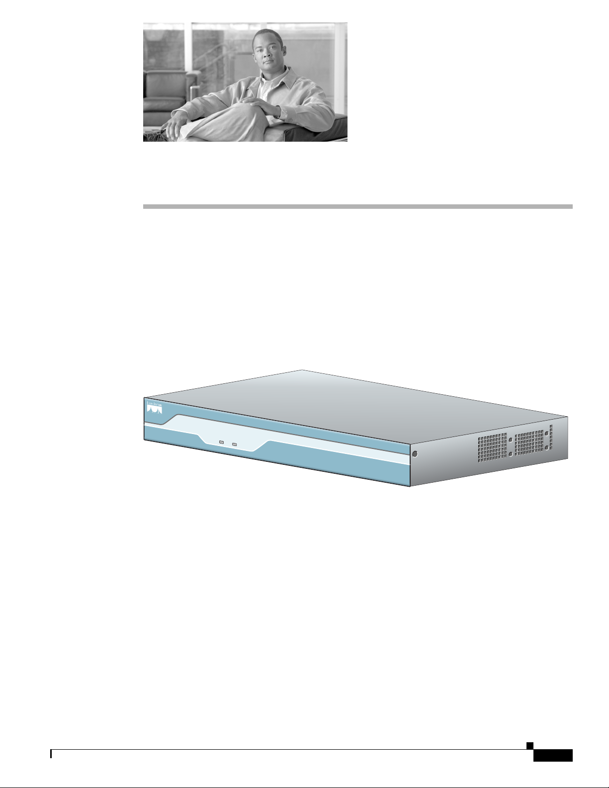
The Cisco 1805 DOCSIS cable router is a data-only device for desktop use. (See Figure 1-1.)
Figure 1-1 Cisco 1805 Cable Router
This chapter describes the features and specifications of the router and includes the following sections:
• Product Description, page 1-1
• Hardware Features, page 1-2
• Chassis Views, page 1-5
• Interface Numbering, page 1-6
• Specifications, page 1-6
Product Description
The Cisco 1805 cable router ships with a Cisco cable modem high-speed WAN interface card (HWIC)
installed in slot 0 and with a Cisco 10/100BASE-T Ethernet switch HWIC installed in slot 1. Both of
these cards must be installed in order for the router to be operational. If either card is removed, the router
will default to ROMMON state.
SYS
SYS
PWR
ACT
Cisco 1800
Series
122331
OL-14661-01
Cisco 1805 DOCSIS Cable Router Hardware Installation Guide
1-1
Page 2
Hardware Features
REVIEW DRAFT—CISCO CONFIDENTIAL
The Cisco cable modem HWIC installed in slot 0 is designed to be fully compliant with DOCSIS 2.0
standards in the United States, Europe, and Japan. The cable modem HWICs provide secure, high-speed
connections over cable modem hybrid fiber-coaxial (HFC) cable network.
With the Cisco 10/100BASE-T Ethernet switch HWIC installed in slot 1, the Cisco 1805 cable router
provides Layer 2 switching for traffic between one port on the HWIC and any other port on the same
HWIC. This HWIC also supports Layer 3 traffic to and from the HWIC and any of the other platform
interfaces. Traffic between different VLANs on the switch is routed through the router.
Hardware Features
This section describes the basic features of the Cisco 1805 cable router. It contains the following:
• Product Serial Number Location, page 1-2
• Built-In Interfaces, page 1-3
• Memory, page 1-3
• LED Indicators, page 1-4
• Chassis Ventilation, page 1-4
Chapter 1 Product Description
• Real-Time Clock, page 1-4
• Chassis Security, page 1-5
Product Serial Number Location
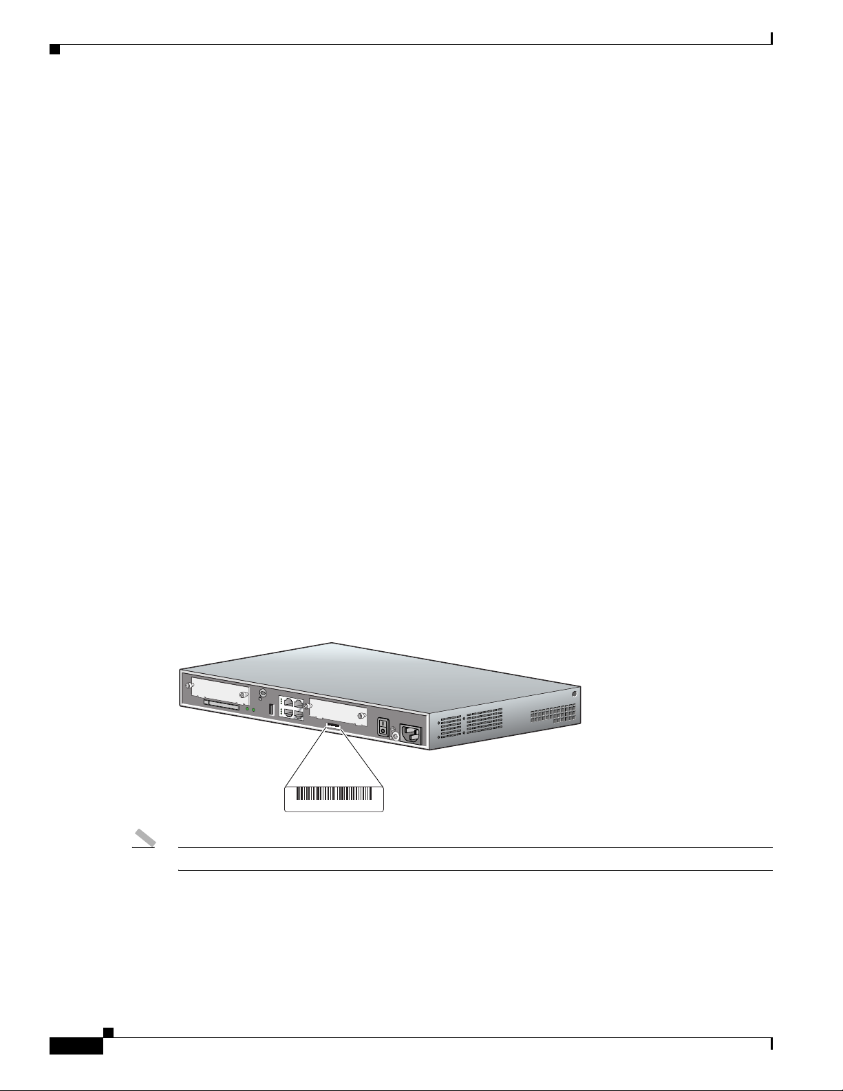
The serial number label for Cisco 1805 cable router is located on the back of the chassis, below interface
card slot 0. (See Figure 1-2.)
Figure 1-2 Serial Number Location
SN: AAANNNNXXXX
SN: AAANNNNXXXX
CISCO 1841
100-240 VAC-
50/60 Hz
1 A
122334
1-2
Note The serial number for Cisco 1805 cable router is 11 characters long.
Cisco 1805 DOCSIS Cable Router Hardware Installation Guide
OL-14661-01
Page 3

Chapter 1 Product Description
REVIEW DRAFT—CISCO CONFIDENTIAL
Cisco Product Identification Tool
The Cisco Product Identification (CPI) tool provides detailed illustrations and descriptions showing
where to locate serial number labels on Cisco products. The tool includes the following features:
• A search option that allows browsing for models by using a tree-structured product hierarchy
• A search field on the final results page which makes it easier to look up multiple products
• Clearly identified end-of-sale products in results lists
The tool streamlines the process of locating serial number labels and identifying products. Serial number
information expedites the entitlement process and is important for access to support services.
The Cisco Product Identification tool can be accessed at the following URL:
http://tools.cisco.com/Support/CPI/index.do
Built-In Interfaces
This section summarizes the interfaces available on the Cisco 1805 cable router:
• Two Fast Ethernet ports (RJ-45 connectors)
• High-speed console and auxiliary ports, up to 115.2 kbps each (RJ-45 connectors)
• One USB port (version 1.1), intended for future use
Hardware Features
Memory
The Cisco 1805 cable routers contain the following types of memory:
• SDRAM—Serves two functions. It stores the running configuration and routing tables, and it is used
for packet buffering by the network interfaces. The Cisco IOS software executes from SDRAM.
• Flash memory—Stores the operating system software image, configuration files, and log files,
implemented in an external CompactFlash memory card.
• Boot/NVRAM—Serves two functions. It stores the ROM monitor, which allows you to boot an
operating system software image from flash memory. It also stores the system configuration file and
the virtual configuration register.
Table 1-1 lists the memory specifications for Cisco 1805 cable routers.
Table 1-1 Router Memory Specifications
Description Specification
SDRAM 128 MB, expandable to 384 MB; default is 128 MB
Flash memory 32, 64, or 128 MB; default is 64 MB
Boot or NVRAM 2/4 MB flash memory
Note SDRAM and the flash memory are user upgradable, but the boot or NVRAM is permanently soldered to
the router’s motherboard and is not upgradable.
OL-14661-01
Cisco 1805 DOCSIS Cable Router Hardware Installation Guide
1-3
Page 4

Hardware Features
LED Indicators
Chapter 1 Product Description
REVIEW DRAFT—CISCO CONFIDENTIAL
Table 1-2 summarizes the LED indicators that are located in the router bezel or chassis, but not in the
interface cards installed in slot 0 or slot 1.
Table 1-2 Summary of Cisco 1805 DOCSIS Cable Router LED Indicators
LED Color Description Location:
SYS PWR Green Router has successfully booted up and the software is functional.
This LED blinks while booting or in the ROM monitor.
SYS ACT Green Blinking when any packets are transmitted or received on any
WAN or LAN, or during monitoring system activity.
CF Green On when flash memory is busy. Do not remove the CompactFlash
memory card when this light is on.
FDX (FE 0/0) Green On indicates full-duplex operation. Off indicates half-duplex
operation.
100 (FE 0/0) Green On indicates a 100-Mbps link. Off indicates a 10-Mbps link. Back
Link (FE 0/0) Green On when the router is correctly connected to a local Ethernet
LAN through Ethernet port 0.
FDX (FE 0/1) Green On indicates full-duplex operation. Off indicates half-duplex
operation.
100 (FE 0/1) Green On indicates a 100-Mbps link. Off indicates a 10-Mbps link. Back
Link (FE 0/1) Green On when the router is correctly connected to a local Ethernet
LAN through Ethernet port 1.
AIM Green On indicates presence of an AIM in the internal AIM slot. Back
Front
panel
Front
panel
Back
panel
Back
panel
panel
Back
panel
Back
panel
panel
Back
panel
panel
Chassis Ventilation
An internal three-speed fan provides chassis cooling. An onboard temperature sensor controls the fan
speed. The fan is always on when power is applied to the router. Under most conditions, the fan operates
at the slowest speed to conserve power and reduce fan noise. It operates at higher speeds when necessary
in conditions of higher ambient temperature.
Real-Time Clock
On system power up, an internal real-time clock with battery backup provides the system software with
time of day. This allows the system to verify the validity of a certification authority (CA) certificate. The
backup battery is a socketed lithium battery. This battery lasts the life of the router under the operating
environmental conditions specified for the router, and is not field replaceable.
Cisco 1805 DOCSIS Cable Router Hardware Installation Guide
1-4
OL-14661-01
Page 5

Chapter 1 Product Description
REVIEW DRAFT—CISCO CONFIDENTIAL
Note If the lithium battery in a Cisco 1805 router should fail, the router must be returned to Cisco for repair.
Do not replace the battery yourself. Although the battery is not intended to be field replaceable, the
safety agencies require the following warning to be included in this document.
Chassis Views
Warning
There is the danger of explosion if the battery is replaced incorrectly. Replace the battery only with
the same or equivalent type recommended by the manufacturer. Dispose of used batteries according
to the manufacturer’s instructions.
Chassis Security
The chassis of the Cisco 1805 cable router is constructed with a Kensington security slot on the back
panel. It can be secured to a desktop or other surface by using Kensington lockdown equipment.
Chassis Views
This section provides views of the front and back panels of Cisco 1805 cable routers, showing the
locations of the power and signal interfaces, the interface card slots, and the status indicators.
Figure 1-3 shows the front panel of a Cisco 1805 cable router.
Figure 1-3 Front Panel of the Cisco 1805 Cable Router
Statement 1015
Cisco 1800
SYS
SYS
ACT
PWR
Series
122329
OL-14661-01
1 2
1 System power (SYS PWR) LED 2 System activity (SYS ACT) LED
Figure 1-4 shows the back panel of a Cisco 1805 cable router.
Figure 1-4 Back Panel of the Cisco 1805 Cable Router
13
1
100-240 VAC-
1 A
50/60 Hz
HWIC
4ESW
PWR 3x LNK PWR 2x LNK PWR 1x LNK PWR 0x LNK
DO NOT REMOVE DURING NETWORK OPERATION
8
8
CF AIM
9
10
2
CISCO 1841
CABLE
37
SLOT 0SLOT 1
DS
LINK
US
POWER
ONLINE
4
11
FDX
100
LINK
FDX
100
LINK
5
FE 0/1 CONSOLE
FE 0/0 AUX
125
HWICCABLE-D-2
6
Cisco 1805 DOCSIS Cable Router Hardware Installation Guide
232505
1-5
Page 6

Interface Numbering
REVIEW DRAFT—CISCO CONFIDENTIAL
1 Input power connection 8 CompactFlash memory card slot
2 On/Off switch 9 CompactFlash LED
3 Slot 0 (cable modem HWIC) 10 AIM LED
4 Console port 11 USB port
5 Fast Ethernet ports and LEDs 12 Auxiliary port
6 Kensington security slot 13 Chassis ground connection
7 Slot 1 (4ESW HWIC)
Interface Numbering
Each individual interface (port) on a Cisco 1805 cable router is identified by a number. A Cisco 1805
cable router contains the following wide-area network (WAN) and local-area network (LAN) interface
types:
• Two onboard FastEthernet LAN interfaces
Chapter 1 Product Description
• Slot 0 Cisco cable modem HWIC
• Slot 1 Cisco 4-port 10/100BASE-T Ethernet switch HWIC
The numbering format for the slots is interface-type 0/slot-number/interface-number. Tab le 1-3
summarizes the interface numbering.
Table 1-3 Interface Numbering
Slot Number Slot Type Slot Numbering Range Example
Onboard ports Fast Ethernet 0/0 and 0/1 interface fastethernet 0/0
Slot 0 HWIC 0/0/0 to 0/0/3 cable-modem 0/0/0
Slot 1 HWIC 0/1/0 to 0/1/3 fastethernet 0/1/0
Specifications
Table 1-4 lists the specifications for Cisco 1805 DOCSIS cable router.
Table 1-4 Cisco 1805 Cable Router Specifications
line async 0/0/0
line async 0/1/0
1-6
Description Specification
Dimensions (H x W x D) 1.73 x 13.5 x 10.8 in. (4.4 x 34.3 x 27.4 cm) without rubber feet
1.87 in. (4.75 cm) height with rubber feet
Weight 6.1 lb (2.77 kg)
Input voltage, AC power supply 100 to 240 VAC, autoranging
Frequency 47 to 63 Hz
Cisco 1805 DOCSIS Cable Router Hardware Installation Guide
OL-14661-01
Page 7

Chapter 1 Product Description
REVIEW DRAFT—CISCO CONFIDENTIAL
Table 1-4 Cisco 1805 Cable Router Specifications (continued)
Description Specification
Power consumption 20W maximum for an unloaded unit.
Console and auxiliary ports RJ-45 connectors
Operating humidity 5 to 95%, noncondensing
Operating temperature 32 to 104°F (0 to 40°C)
Nonoperating temperature shock –13 to 158°F (–25 to 70°C) at 9° F (5° C)/minute minimum
Noise level Normal operating temperature (< 78° F or 26°C): 34 dBa
Regulatory compliance For detailed regulatory compliance information, see the
Electromagnetic compatibility FCC Part 15 Class A.
Safety compliance UL 60950; CSA 60950; IEC 60950; EN 60950; AS/NZS 3260;
Specifications
With two WICs and an AIM installed, power consumption will be
less than 50W.
From (78° F or 26°C) through (104° F or 40°C): 37 dBa
Higher than 104° F or 40°C: 42 dBa
Regulatory Compliance and Safety Information for Cisco 1840
Routers document available online.
NOM-019-SCFI-1998.
Table 1-5 lists the specifications for the Cisco 10/100BASE-T Ethernet switch HWIC LEDs.
Table 1-5 Cisco 10/100BASE-T Ethernet Switch HWIC LEDs
LED Color Definition State
LNK Green Link status ON = Link pulses detected
OFF = No link pulses detected
ILP Green or amber Inline power status GREEN = Providing power to the
device
AMBER BLINKING = Power delivery
fault or denial
AMBER = Power administratively
disabled
OFF = No external device detected, or
inline power option not installed
Table 1-6 lists the specifications for the the Cisco cable modem HWIC LEDs.
Table 1-6 Cisco Cable Modem HWIC LEDs
LED State Description
US FLASHING The cable modem is scanning for a DOCSIS channel and
tries to lock on an upstream signal.
SOLID The cable modem is locked on to the US DOCSIS channel.
OL-14661-01
Cisco 1805 DOCSIS Cable Router Hardware Installation Guide
1-7
Page 8

Specifications
Chapter 1 Product Description
REVIEW DRAFT—CISCO CONFIDENTIAL
Table 1-6 Cisco Cable Modem HWIC LEDs (continued)
LED State Description
ONLINE FLASHING The cable modem is establishing a connection to the router.
SOLID The cable modem is synchronized with the router.
LINK ON A link is active when a CPE device is connected and the
cable modem is not bridging data.
BLINKING The cable modem is bridging data in the cable modem
operational state.
Note The LINK LED does not pulse for data traffic that
originates or terminates at the cable modem.
POWER ON The cable modem is powered on.
SOLID It stays solid after the power-on self-test (POST).
RED The self-test has failed.
1-8
Cisco 1805 DOCSIS Cable Router Hardware Installation Guide
OL-14661-01
 Loading...