

Page 1
Quick Start Guide
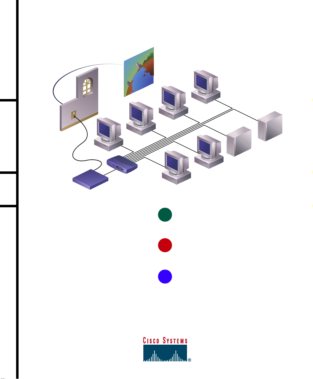
INSTALLING YOUR CISCO 1417 ROUTER
ADSL connection
PC
Cisco 1407/1417
Internet
PC
PC
Hub
PC
1
UNPACK THE BOX
PC
Server
Server
PC
2
INSTALL THE ROUTER
3
VERIFY YOUR INSTALLATION
Page 2
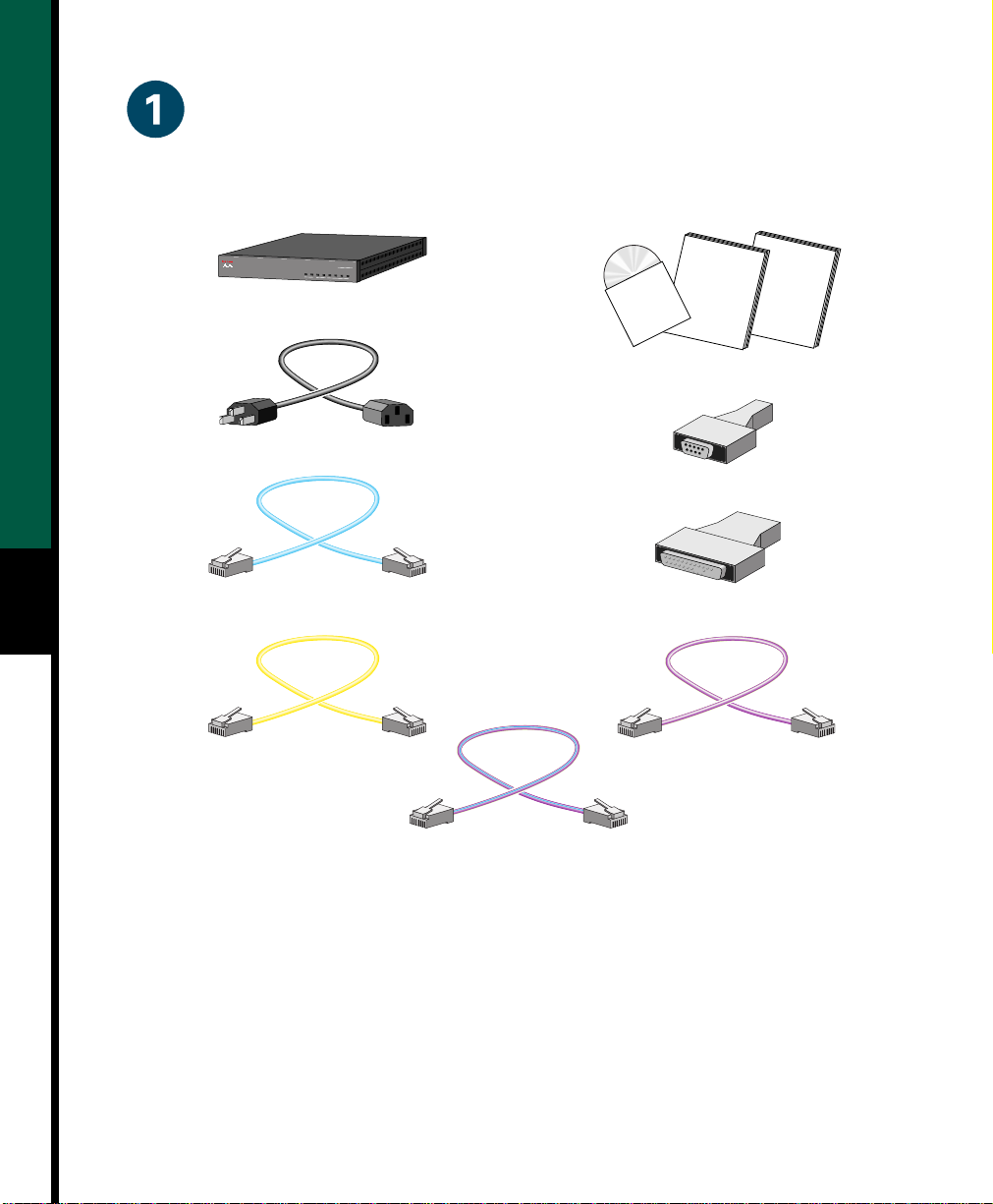
Unpack the Box
When you unpack the box that contains your Cisco 1417 router, you should find the items
shown below. If you did not receive everything shown here, contact your Cisco reseller.
Cisco 1400
SERIES
COLLACTOKPWR
CARRIER
LPACT
AL
SYSTEM ETHERNET WAN
Router
Power cord (black)
Documentation
CD-ROM
DB-9 to RJ-45 console adapter (gray)
Installation
and
Configuration
Guide
Quick
Start
Guide
Product documentation
Console cable
2
(blue, RJ-45 to RJ-45)
Ethernet cable
(yellow, RJ-45 to RJ-45)
DB-25 to RJ-45 console adapter (gray)
ADSL cable
(purple, RJ-11 to RJ-11)
POTS crossover cable (if ordered)
(purple with blue stripe, RJ-11 to RJ-11)
17498
Items You Must Provide
• 10BaseT Ethernet hub or switch to connect the router to the local network.
• POTS splitter for optimal router performance when using aphone onthe same ADSL line
as the router.
• Microfilter(s), if needed for improving phone call quality.
If you arenot sure whento use POTSsplitters and microfilters,read the “Installation”chapter
of the hardware installation guidethat came with your router. If youare not sure what type of
splitter or microfilter to use, contact your ISP or your Cisco reseller.
Page 3
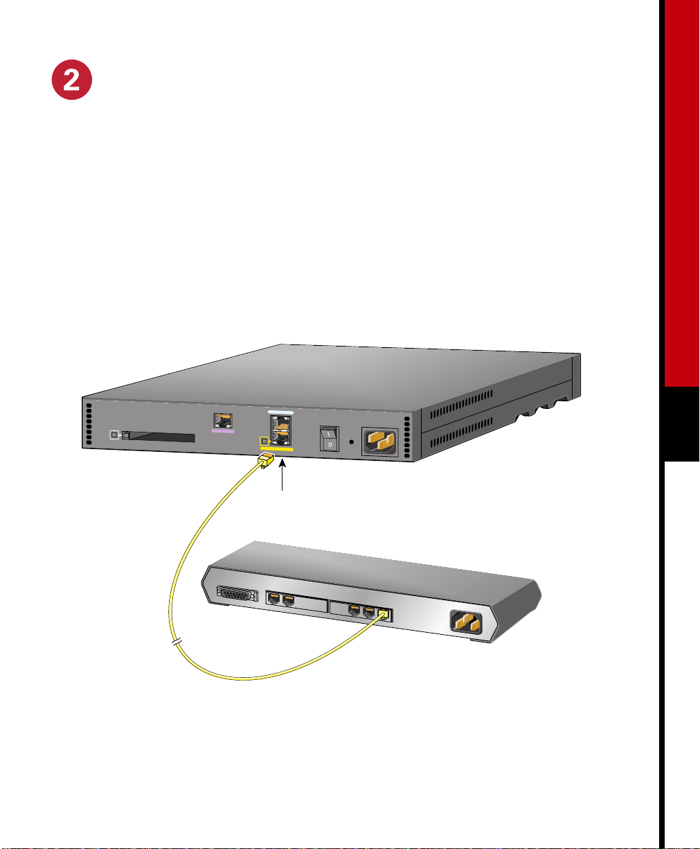
Install the Router
A. Connect the router to the local network
Use the included yellowEthernet cable for connectingtherouter to thelocalEthernet network.
For more information on this cable, refer to the “Cabling Specifications” chapter in the
hardware installation guide that came with the router.
Step 1 Connect one end of the yellow Ethernet cable to the yellow ETHERNET port.
Step 2 Connect the other end to a port on the Ethernet hub or switch.
Cisco 1417
CONSOLE
OK FLASH PC CARD
ADSL
LNK
ETHERNET
3
Ethernet port
AUI
8
Straight-through
Ethernet cable
7
1
17499
Ethernet hub or switch
Page 4
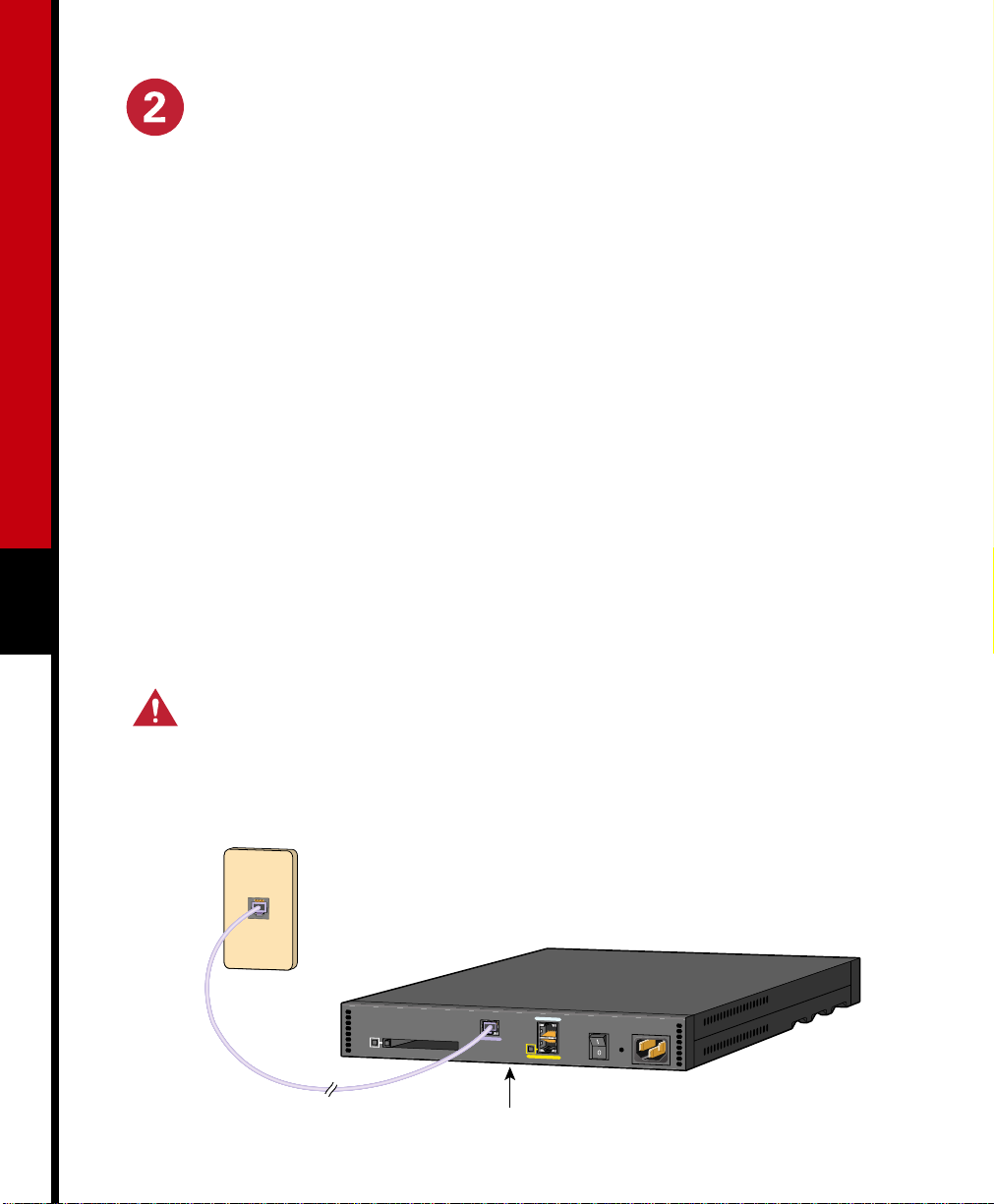
Install the Router (continued)
B. Connect the router to the ADSL line
Use the included purple ADSL cable for connecting the router to the ADSL line.
Step 1 Connect one end of the purple cable to the purple ADSL port on the router.
Step 2 Connect the other end of the purple cable to the ADSL wall jack.
Note: If you are connecting therouter to a POTS splitter that usesdata port pins 3 and 4 for
data, you should use the purple cable with the blue stripe. If you are notsure about what type
of POTS splitter to use, contact your ADSL service provider or your Cisco reseller.
Step 3 Either install aPOTS splitter, orconfirm that your serviceprovider installed aPOTS
splitter. If you are not sure about what type of POTS splitter to use, contact your
ADSL service provider or your Cisco reseller.
Step 4 Install microfilters if you need them for optimal telephone call quality.
4
Note: Refer to the “Using POTS Splitters and Microfilters” section in the “Installation”
chapter of the installation and configuration guide for information on when to use POTS
splitters and microfilters.
Caution Always connect the purple ADSL cable to the purple ADSL port. Do not
connect the cable to the Ethernet port or to the console port. This will damage your
router.
ADSL
(RJ-11)
wall jack
Cisco 1417
CONSOLE
ADSL
RJ-11 cable
OK FLASH PC CARD
LNK
ADSL port
ETHERNET
17500
Page 5

Install the Router (continued)
C. Connect a PC to the router
To use Cisco IOS software to configure the router, it must be connected to a terminal or to a
PC with terminal-emulationsoftware. Terminal-emulation softwareshould be configuredwith
the following settings: 9600 baud, 8 data bits, no parity bits, and 1 stop bit.
Take the following steps to connect the router to one of these devices:
Step 1 Connect one end ofthe blue console cable (included) to the CONSOLE port on the
router rear panel.
Step 2 Depending on the console port connector (DB-25 or DB-9)on your terminal or PC,
connect one of the gray adapters (included) to the other end of the console cable.
Step 3 Connect the gray adapter to the DB-25 or DB-9 connector on your terminal or PC.
5
OK FLASH PC CARD
Cisco 1417
CONSOLE
ADSL
LNK
ETHERNET
Console cable
To PC or terminal
17501
Page 6
Install the Router (continued)
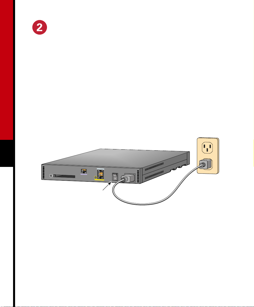
D. Connect the power cord
Step 1 Connect the power-supply cord to the power socket on the rear panel.
Step 2 Connect the other end of the cord to a power outlet.
Step 3 Turn on the router by pressing the power switch to the on ( | ) position.
Step 4 Confirm that the router has power bycheckingthatthePWRLED on the front panel
is on.
6
Cisco 1417
OK FLASH PC CARD
CONSOLE
ADSL
LNK
ETHERNET
17502
Power switch
Page 7

Verify Your Installation.
After the router is powered up, the following LEDs confirm that you have correctly installed
your router.
LED Location What to Look for
PWR Front On when power is being supplied to the router.
OK Front • One blink per second when the router is in ROM monitor
mode.
• Several blinks per second when the router is running the boot
image in ROM monitor.
• On steady when the Cisco IOS software is loaded and
functional.
LNK Rear On when the router is correctly connected to the local Ethernet
network through the ETHERNET port.
WAN CARRIER Front On when the router has synchronized with the DSL access
multiplexer (DSLAM) at the service provider office.
ETHERNET ACT Front Blinking when there is network traffic on the Ethernet LAN.
OK Rear On when the Flash PC card is correctly installed in the router. If
this LED is off, refer to the installation and configuration guide
that came with your router forinstructionson how to reinstall the
Flash PC card.
7
For More Information
For more information about installing or configuring your Cisco 1417 router, refer to the
following sources:
• Cisco 1400 Series Router Installation and Configuration Guide (in the accessory kit).
• The Cisco Connection Online card in the accessory kit, which lists telephone numbers,
e-mail addresses, and URLs for getting information directly from Cisco Systems.
Page 8

Corporate Headquarters
Cisco Systems, Inc.
170 West Tasman Drive
San Jose, CA 95134-1706
USA
http://www.cisco.com
Tel: 408 526-4000
800 553-NETS (6387)
Fax: 408 526-4100
European Headquarters
Cisco Systems Europe s.a.r.l.
Parc Evolic, Batiment L1/L2
16 Avenue du Quebec
Villebon, BP 706
91961 Courtaboeuf Cedex
France
http://www-europe.cisco.com
Tel: 33 1 6918 61 00
Fax: 33 1 6928 83 26
Americas
Headquarters
Cisco Systems, Inc.
170 West Tasman Drive
San Jose, CA 95134-1706
USA
http://www.cisco.com
Tel: 408 526-7660
Fax: 408 527-0883
Asia Headquarters
Nihon Cisco Systems K.K.
Fuji Building, 9th Floor
3-2-3 Marunouchi
Chiyoda-ku, Tokyo 100
Japan
http://www.cisco.com
Tel: 81 3 5219 6250
Fax: 81 3 5219 6001
Cisco Systems has more than 200 offices in the following countries. Addresses, phone numbers, and fax numbers are listed on the
Cisco Connection Online Web site at http://www.cisco.com.
Argentina • Australia • Austria • Belgium • Brazil • Canada • Chile • China (PRC) • Colombia • Costa Rica • Czech Republic • Denmark
• France • Germany • Greece • Hungary • India • Indonesia • Ireland • Israel • Italy • Japan • Korea • Luxembourg • Malaysia
England
• The Netherlands • New Zealand • Norway • Peru • Philippines • Poland • Portugal • Russia • Saudi Arabia • Scotland • Singapore
Mexico
South Africa
Copyright © 1999, Cisco Systems, Inc. All rights reserved. Access Registrar, AccessPath, Any to Any,AtmDirector, CCDA, CCDE, CCDP,CCIE, CCNA, CCNP, CCSI, CD-PAC, the
Cisco logo, Cisco Certified Internetwork Expert logo, CiscoLink, the Cisco Management Connection logo, the Cisco NetWorkslogo, the Cisco Powered Network logo, Cisco Systems
Capital, the Cisco Systems Capital logo, Cisco Systems Networking Academy, the Cisco Technologies logo, ControlStream, Fast Step, FireRunner,GigaStack, IGX, JumpStart, Kernel
Proxy,MGX, Natural Network Viewer, NetSonar,Network Registrar,Packet, PIX, Point and Click Internetworking, Policy Builder, Precept, RouteStream, Secure Script, ServiceWay,
SlideCast, SMARTnet, StreamView, The Cell, TrafficDirector, TransPath, ViewRunner, VirtualStream, VisionWay, VlanDirector, Workgroup Director, and Workgroup Stack are
trademarks; Changing the Way WeWork, Live, Play, and Learn, Empowering the Internet Generation, The Internet Economy, and The New Internet Economy are service marks; and
Asist, BPX, Catalyst, Cisco, Cisco IOS, the Cisco IOS logo, Cisco Systems, the Cisco Systems logo, the Cisco Systems Cisco Press logo, Enterprise/Solver, EtherChannel, EtherSwitch,
FastHub, FastLink, FastPAD, FastSwitch, IOS, IP/TV, IPX, LightStream, LightSwitch, MICA, NetRanger, Registrar, StrataView Plus, Stratm, Telerouter, and VCO are registered
trademarks of Cisco Systems, Inc. in the U.S. and certain other countries. All other trademarks mentioned in this document are the property of their respective owners. (9903b R)
• Spain • Sweden • Switzerland • Taiwan, ROC • Thailand • Turkey • United Arab Emirates • United States •
Printed in the USA on recycled paper containing 10% postconsumer waste.
DOC-785467=
78-5467-01
 Loading...