

Page 1

Cisco Aironet 1300 Series Outdoor Access Point/Bridge Hardware Installation Guide
April 2005
Corporate Headquarters
Cisco Systems, Inc.
170 West Tasman Drive
San Jose, CA 95134-1706
USA
http://www.cisco.com
Tel: 408 526-4000
800 553-NETS (6387)
Fax: 408 526-4100
Text Part Number: OL-5048-02
Page 2

THE SPECIFICATIONS AND INFORMATION REGARDING THE PRODUCTS IN THIS MANUAL ARE SUBJECT TO CHANGE WITHOUT NOTICE. ALL
STATEMENTS, INFORMATION, AND RECOMMENDATIONS IN THIS MANUAL ARE BELIEVED TO BE ACCURATE BUT ARE PRESENTED WITHOUT
WARRANTY OF ANY KIND, EXPRESS OR IMPLIED. USERS MUST TAKE FULL RESPONSIBILITY FOR THEIR APPLICATION OF ANY PRODUCTS.
THE SOFTWARE LICENSE AND LIMITED WARRANTY FOR THE ACCOMPANYING PRODUCT ARE SET FORTH IN THE INFORMATION PACKET THAT
SHIPPED WITH THE PRODUCT AND ARE INCORPORATED HEREIN BY THIS REFERENCE. IF YOU ARE UNABLE TO LOCATE THE SOFTWARE LICENSE
OR LIMITED WARRANTY, CONTACT YOUR CISCO REPRESENTATIVE FOR A COPY.
The following information is for FCC compliance of Class A devices: This equipment has been tested and found to comply with the limits for a Class A digital device, pursuant
to part 15 of the FCC rules. These limits are designed to provide reasonable protection against harmful interference when the equipment is operated in a commercial
environment. This equipment generates, uses, and can radiate radio-frequency energy and, if not installed and used in accordance with the instruction manual, may cause
harmful interference to radio communications. Operation of this equipment in a residential area is likely to cause harmful interference, in which case users will be required
to correct the interference at their own expense.
The following information is for FCC compliance of Class B devices: The equipment described in this manual generates and may radiate radio-frequency energy. If it is not
installed in accordance with Cisco’s installation instructions, it may cause interference with radio and television reception. This equipment has been tested and found to
comply with the limits for a Class B digital device in accordance with the specifications in part 15 of the FCC rules. These specifications are designed to provide reasonable
protection against such interference in a residential installation. However, there is no guarantee that interference will not occur in a particular installation.
Modifying the equipment without Cisco’s written authorization may result in the equipment no longer complying with FCC requirements for Class A or Class B digital
devices. In that event, your right to use the equipment may be limited by FCC regulations, and you may be required to correct any interference to radio or television
communications at your own expense.
You can determine whether your equipment is causing interference by turning it off. If the interference stops, it was probably caused by the Cisco equipment or one of its
peripheral devices. If the equipment causes interference to radio or television reception, try to correct the interference by using one or more of the following measures:
• Turn the television or radio antenna until the interference stops.
• Move the equipment to one side or the other of the television or radio.
• Move the equipment farther away from the television or radio.
• Plug the equipment into an outlet that is on a different circuit from the television or radio. (That is, make certain the equipment and the television or radio are on circuits
controlled by different circuit breakers or fuses.)
Modifications to this product not authorized by Cisco Systems, Inc. could void the FCC approval and negate your authority to operate the product.
The Cisco implementation of TCP header compression is an adaptation of a program developed by the University of California, Berkeley (UCB) as part of UCB’s public
domain version of the UNIX operating system. All rights reserved. Copyright © 1981, Regents of the University of California.
NOTWITHSTANDING ANY OTHER WARRANTY HEREIN, ALL DOCUMENT FILES AND SOFTWARE OF THESE SUPPLIERS ARE PROVIDED “AS IS” WITH
ALL FAULTS. CISCO AND THE ABOVE-NAMED SUPPLIERS DISCLAIM ALL WARRANTIES, EXPRESSED OR IMPLIED, INCLUDING, WITHOUT
LIMITATION, THOSE OF MERCHANTABILITY, FITNESS FOR A PARTICULAR PURPOSE AND NONINFRINGEMENT OR ARISING FROM A COURSE OF
DEALING, USAGE, OR TRADE PRACTICE.
IN NO EVENT SHALL CISCO OR ITS SUPPLIERS BE LIABLE FOR ANY INDIRECT, SPECIAL, CONSEQUENTIAL, OR INCIDENTAL DAMAGES, INCLUDING,
WITHOUT LIMITATION, LOST PROFITS OR LOSS OR DAMAGE TO DATA ARISING OUT OF THE USE OR INABILITY TO USE THIS MANUAL, EVEN IF CISCO
OR ITS SUPPLIERS HAVE BEEN ADVISED OF THE POSSIBILITY OF SUCH DAMAGES.
CCSP, CCVP, the Cisco Square Bridge logo, Follow Me Browsing, and StackWise are trademarks of Cisco Systems, Inc.; Changing the Way We Work, Live, Play, and Learn, and
iQuick Study are service marks of Cisco Systems, Inc.; and Access Registrar, Aironet, ASIST, BPX, Catalyst, CCDA, CCDP, CCIE, CCIP, CCNA, CCNP, Cisco, the Cisco
Certified Internetwork Expert logo, Cisco IOS, Cisco Press, Cisco Systems, Cisco Systems Capital, the Cisco Systems logo, Cisco Unity, Empowering the Internet Generation,
Enterprise/Solver, EtherChannel, EtherFast, EtherSwitch, Fast Step, FormShare, GigaDrive, GigaStack, HomeLink, Internet Quotient, IOS, IP/TV, iQ Expertise, the iQ logo, iQ
Net Readiness Scorecard, LightStream, Linksys, MeetingPlace, MGX, the Networkers logo, Networking Academy, Network Registrar, Pac ke t , PIX, Post-Routing, Pre-Routing,
ProConnect, RateMUX, ScriptShare, SlideCast, SMARTnet, StrataView Plus, TeleRouter, The Fastest Way to Increase Your Internet Quotient, and TransPath are registered
trademarks of Cisco Systems, Inc. and/or its affiliates in the United States and certain other countries.
All other trademarks mentioned in this document or Website are the property of their respective owners. The use of the word partner does not imply a partnership relationship
between Cisco and any other company. (0502R)
Cisco Aironet 1300 Series Outdoor Access Point/Bridge Hardware Installation Guide
© 2005 Cisco Systems, Inc. All rights reserved.
Page 3

Preface ix
Objectives ix
Audience ix
Organization ix
Conventions x
Related Publications xii
Obtaining Documentation xii
Cisco.com xii
Documentation DVD xiii
Ordering Documentation xiii
Documentation Feedback xiii
CONTENTS
CHAPTER
Cisco Product Security Overview xiv
Reporting Security Problems in Cisco Products xiv
Obtaining Technical Assistance xiv
Cisco Technical Support Website xv
Locating the Product Serial Number xv
Submitting a Service Request xvi
Definitions of Service Request Severity xvii
Obtaining Additional Publications and Information xvii
1 Overview 1-1
Key Features 1-2
Power 1-3
Integrated Antenna 1-3
External Antenna 1-4
Ethernet Ports 1-4
Enclosure 1-4
Connectors 1-4
LEDs 1-5
Operating Roles 1-6
OL-5048-02
Network Configuration Examples 1-7
Point-to-Point Bridge Configuration 1-7
Port Aggregation or Redundancy Bridge Configuration 1-7
Point-to-Multipoint Bridge Configuration 1-8
Cisco Aironet 1300 Series Outdoor Access Point/Bridge Hardware Installation Guide
iii
Page 4

Contents
Access Point Configuration 1-8
Workgroup Bridge Configuration 1-9
CHAPTER
CHAPTER
2 Installation Overview 2-1
Safety Warnings 2-2
All Installations 2-2
Outdoor and Vehicle Installations 2-3
Vehicle Bridge Installations 2-3
Safety Information 2-3
FCC Safety Compliance Statement 2-3
Safety Precautions 2-4
Typical Outdoor Installation Components 2-5
Installation Guidelines 2-5
Site Surveys 2-6
Unpacking the Access Point/Bridge 2-6
Package Contents 2-6
Before Beginning the Installation 2-7
Installation Summary 2-9
3 Mounting and Alignment Overview 3-1
Mounting the Access Point/Bridge 3-2
CHAPTER
Mounting Hardware 3-2
Window Mounting 3-3
Multi-Function Mount 3-3
Access Point/Bridge Bracket 3-4
Mast Bracket 3-4
LEDs 3-5
Aligning the Bridge Antenna Using RSSI LED Indications 3-7
4 Using the Web-Browser Interface 4-1
Using the Web-Browser Interface Management Pages 4-2
Using Action Buttons 4-3
Character Restrictions in Entry Fields 4-4
Using Online Help 4-4
Connecting Locally to the Ethernet Port 4-5
iv
Cisco Aironet 1300 Series Outdoor Access Point/Bridge Hardware Installation Guide
OL-5048-02
Page 5

Contents
CHAPTER
5 Configuring the Access Point/Bridge for the First Time 5-1
Before You Start 5-2
Resetting the Access Point/Bridge to Default Settings 5-2
Default IP Address Behavior 5-2
Default SSID and Default Role 5-3
Obtaining and Assigning an IP Address 5-3
Connecting to the Access Point/Bridge Locally 5-3
Using the Power Injector’s Ethernet Port 5-3
Using the Power Injector’s Console Port 5-4
Assigning Basic Settings 5-4
Default Settings on the Express Setup Page 5-8
Enabling the Radio Interfaces 5-9
Adjusting Output Power Level 5-9
Configuring Basic Security Settings 5-9
Understanding Express Security Settings 5-11
Using VLANs 5-11
Express Security Types 5-11
Express Security Limitations 5-12
Using the Express Security Page 5-13
CHAPTER
Finding the IP Address Using the CLI 5-13
Assigning an IP Address Using the CLI 5-14
Using a Telnet Session to Access the CLI 5-14
6 Using the Command-Line Interface 6-1
Connecting to the Console Serial Port 6-2
Using a Telnet Session to Open the CLI 6-3
Using Secure Shell to Open the CLI 6-3
IOS Command Modes 6-4
Getting Help 6-5
Abbreviating Commands 6-5
Using no and default Forms of Commands 6-5
Understanding CLI Messages 6-6
Using Command History 6-6
Changing the Command History Buffer Size 6-7
Recalling Commands 6-7
Disabling the Command History Feature 6-7
OL-5048-02
Using Editing Features 6-8
Cisco Aironet 1300 Series Outdoor Access Point/Bridge Hardware Installation Guide
v
Page 6

Contents
Enabling and Disabling Editing Features 6-8
Editing Commands Through Keystrokes 6-8
Editing Command Lines That Wrap 6-9
Searching and Filtering Output of show and more Commands 6-10
Assigning an IP Address Using the CLI 6-11
Finding the Access Point/Bridge IP Address Using the CLI 6-11
CHAPTER
7 Troubleshooting 7-1
Checking the LEDs 7-2
Normal Mode LED Indications 7-2
Power Injector 7-5
Checking Power 7-6
Checking Basic Configuration Settings 7-6
Default IP Address Behavior 7-6
Default SSID and Radio Behavior 7-6
Enabling the Radio Interface 7-7
SSID 7-7
Security Settings 7-8
Antenna Alignment 7-8
Running the Carrier Busy Test 7-8
Running the Ping or Link Test 7-9
Resetting the Access Point/Bridge to the Default Configuration 7-10
Using the Web-Browser Interface 7-10
Using the CLI 7-10
APPENDIX
vi
Reloading the Access Point/Bridge Image 7-11
Web-Browser Interface 7-11
Browser HTTP Interface 7-11
Browser TFTP Interface 7-12
Obtaining the Access Point/Bridge Image File 7-13
Obtaining the TFTP Server Software 7-13
A Translated Safety Warnings A-1
Statement 84—Warning Definition A-2
Statement 245B—Explosive Device Proximity Warning A-3
Statement 346—RF Exposure Limits A-4
Statement 1001—Work During Lightning Activity A-5
Statement 1005—Circuit Breaker A-6
Cisco Aironet 1300 Series Outdoor Access Point/Bridge Hardware Installation Guide
OL-5048-02
Page 7

Statement 1022—Disconnect Device A-7
Statement 1024—Ground Conductor A-9
Statement 1030—Equipment Installation A-10
Statement 1033—SELV-IEC 60950 DC Power Supply A-12
Statement 1040—Product Disposal A-13
Statement 1052—Installing and Grounding the Antenna A-15
Contents
APPENDIX
APPENDIX
B Declarations of Conformity and Regulatory Information B-1
Manufacturers Federal Communication Commission Declaration of Conformity Statement B-2
Department of Communications—Canada B-3
Canadian Compliance Statement B-3
European Community, Switzerland, Norway, Iceland, and Liechtenstein B-3
Declaration of Conformity with Regard to the R&TTE Directive 1999/5/EC B-3
Declaration of Conformity for RF Exposure B-5
Guidelines for Operating Cisco Aironet Access Points and Bridges in Japan B-5
Japanese Translation B-5
English Translation B-5
Administrative Rules for Cisco Aironet Access Points and Bridges in Taiwan B-6
All Access Points and Bridges B-6
Chinese Translation B-6
English Translation B-6
Declaration of Conformity Statements B-7
Declaration of Conformity Statements for European Union Countries B-7
C Access Point/Bridge Specifications C-1
Bridge Operating Range C-4
APPENDIX
APPENDIX
OL-5048-02
D Channels and Antenna Settings D-1
Channels D-2
IEEE 802.11g (2.4-GHz Band) D-2
Maximum Power Levels and Antenna Gains D-3
IEEE 802.11g (2.4-GHz Band) D-3
Changing the Access Point/Bridge Output Power D-4
E Console Serial Cable Pinouts E-1
Overview E-2
Signals and Pinouts E-2
Cisco Aironet 1300 Series Outdoor Access Point/Bridge Hardware Installation Guide
vii
Page 8

Contents
APPENDIX
G
LOSSARY
I
NDEX
F Load-Dump Protection for Transportation Vehicles F-1
Load-Dump Protection F-1
viii
Cisco Aironet 1300 Series Outdoor Access Point/Bridge Hardware Installation Guide
OL-5048-02
Page 9

Objectives
Preface
This section describes the objectives, audience, organization, and conventions of the Cisco Aironet 1300
Series Outdoor Access Point/Bridge Hardware Installation Guide.
This publication explains the steps for initial setup and basic configuration of the Cisco Aironet 1300
Series Outdoor Access Point/Bridge supporting 2.4-GHz operation. This publication also provides
troubleshooting information and detailed specifications.
Audience
This publication is for the person installing and configuring the Cisco Aironet 1300 Series Outdoor
Access Point/Bridge (called the access point/bridge) for the first time. The installer should be familiar
with network structures, terms, and concepts.
Organization
This guide contains the following sections:
Chapter 1, “Overview,” describes the major components, features, and specifications of the access
point/bridge.
Chapter 2, “Installation Overview,” provides warnings, safety information, and information needed
before you begin the installation of your access point/bridge system.
Chapter 3, “Mounting and Alignment Overview,” provides an overview of components and features used
during access point/bridge mounting and antenna alignment operations.
Chapter 4, “Using the Web-Browser Interface,” describes how to use the web-browser interface to
configure the access point/bridge.
Chapter 5, “Configuring the Access Point/Bridge for the First Time,” describes how to enter basic access
point/bridge configuration settings.
Chapter 6, “Using the Command-Line Interface,” describes how to use the command-line interface
(CLI) to configure the access point/bridge.
Chapter 7, “Troubleshooting,” provides solutions to potential problems encountered during setup.
OL-5048-02
Cisco Aironet 1300 Series Outdoor Access Point/Bridge Hardware Installation Guide
ix
Page 10

Conventions
Appendix A, “Translated Safety Warnings,” lists translations of the safety warnings in this publication.
Appendix B, “Declarations of Conformity and Regulatory Information,” describes the regulatory
conventions to which the access point/bridge conforms and provides guidelines for operating access
point/bridges in Japan.
Appendix C, “Access Point/Bridge Specifications,” describes the channels and antenna settings
supported by the regulatory organizations.
Appendix D, “Channels and Antenna Settings,” lists the access point radio channels and the maximum
power levels supported by the world’s regulatory domains.
Appendix E, “Console Serial Cable Pinouts,” identifies the pinouts for the serial cable that connects to
the power injector’s console serial port.
Appendix F, “Load-Dump Protection for Transportation Vehicles,” provides information on the
electrical load-dump protection device and a vendor for the device.
Conventions
This publication uses the following conventions to convey instructions and information:
Preface
• Commands and keywords are in boldface type.
Note Means reader take note. Notes contain helpful suggestions or references to materials not contained in
Caution Means reader be careful. In this situation, you might do something that could result in equipment
Warning
Waarschuwing
Varoitus
this manual.
damage or loss of data.
This warning symbol means danger. You are in a situation that could cause bodily injury. Before
you work on any equipment, be aware of the hazards involved with electrical circuitry and be
familiar with standard practices for preventing accidents. (To see translations of the warnings
that appear in this publication, refer to the appendix “Translated Safety Warnings.”)
Dit waarschuwingssymbool betekent gevaar. U verkeert in een situatie die lichamelijk letsel kan
veroorzaken. Voordat u aan enige apparatuur gaat werken, dient u zich bewust te zijn van de bij
elektrische schakelingen betrokken risico’s en dient u op de hoogte te zijn van standaard
maatregelen om ongelukken te voorkomen. (Voor vertalingen van de waarschuwingen die in deze
publicatie verschijnen, kunt u het aanhangsel “Translated Safety Warnings” (Vertalingen van
veiligheidsvoorschriften) raadplegen.)
Tämä varoitusmerkki merkitsee vaaraa. Olet tilanteessa, joka voi johtaa ruumiinvammaan. Ennen
kuin työskentelet minkään laitteiston parissa, ota selvää sähkökytkentöihin liittyvistä vaaroista
ja tavanomaisista onnettomuuksien ehkäisykeinoista. (Tässä julkaisussa esiintyvien varoitusten
käännökset löydät liitteestä "Translated Safety Warnings" (käännetyt turvallisuutta koskevat
varoitukset).)
Cisco Aironet 1300 Series Outdoor Access Point/Bridge Hardware Installation Guide
x
OL-5048-02
Page 11

Preface
Conventions
Attention
Warnung
Avvertenza
Advarsel
Ce symbole d’avertissement indique un danger. Vous vous trouvez dans une situation pouvant
entraîner des blessures. Avant d’accéder à cet équipement, soyez conscient des dangers posés
par les circuits électriques et familiarisez-vous avec les procédures courantes de prévention des
accidents. Pour obtenir les traductions des mises en garde figurant dans cette publication,
veuillez consulter l’annexe intitulée « Translated Safety Warnings » (Traduction des avis de
sécurité).
Dieses Warnsymbol bedeutet Gefahr. Sie befinden sich in einer Situation, die zu einer
Körperverletzung führen könnte. Bevor Sie mit der Arbeit an irgendeinem Gerät beginnen, seien
Sie sich der mit elektrischen Stromkreisen verbundenen Gefahren und der Standardpraktiken zur
Vermeidung von Unfällen bewußt. (Übersetzungen der in dieser Veröffentlichung enthaltenen
Warnhinweise finden Sie im Anhang mit dem Titel “Translated Safety Warnings” (Übersetzung der
Warnhinweise).)
Questo simbolo di avvertenza indica un pericolo. Si è in una situazione che può causare infortuni.
Prima di lavorare su qualsiasi apparecchiatura, occorre conoscere i pericoli relativi ai circuiti
elettrici ed essere al corrente delle pratiche standard per la prevenzione di incidenti. La
traduzione delle avvertenze riportate in questa pubblicazione si trova nell’appendice, “Translated
Safety Warnings” (Traduzione delle avvertenze di sicurezza).
Dette varselsymbolet betyr fare. Du befinner deg i en situasjon som kan føre til personskade. Før
du utfører arbeid på utstyr, må du være oppmerksom på de faremomentene som elektriske kretser
innebærer, samt gjøre deg kjent med vanlig praksis når det gjelder å unngå ulykker. (Hvis du vil
se oversettelser av de advarslene som finnes i denne publikasjonen, kan du se i vedlegget
"Translated Safety Warnings" [Oversatte sikkerhetsadvarsler].)
Aviso
¡Advertencia!
Varning!
Este símbolo de aviso indica perigo. Encontra-se numa situação que lhe poderá causar danos
fisicos. Antes de começar a trabalhar com qualquer equipamento, familiarize-se com os perigos
relacionados com circuitos eléctricos, e com quaisquer práticas comuns que possam prevenir
possíveis acidentes. (Para ver as traduções dos avisos que constam desta publicação, consulte
o apêndice “Translated Safety Warnings” - “Traduções dos Avisos de Segurança”).
Este símbolo de aviso significa peligro. Existe riesgo para su integridad física. Antes de
manipular cualquier equipo, considerar los riesgos que entraña la corriente eléctrica y
familiarizarse con los procedimientos estándar de prevención de accidentes. (Para ver
traducciones de las advertencias que aparecen en esta publicación, consultar el apéndice
titulado “Translated Safety Warnings.”)
Denna varningssymbol signalerar fara. Du befinner dig i en situation som kan leda till
personskada. Innan du utför arbete på någon utrustning måste du vara medveten om farorna med
elkretsar och känna till vanligt förfarande för att förebygga skador. (Se förklaringar av de
varningar som förekommer i denna publikation i appendix "Translated Safety Warnings"
[Översatta säkerhetsvarningar].)
OL-5048-02
Cisco Aironet 1300 Series Outdoor Access Point/Bridge Hardware Installation Guide
xi
Page 12

Related Publications
Related Publications
For more information about access point/bridges and related products, refer to the following
publications:
• Quick Start Guide: Cisco Aironet 1300 Series Outdoor Access Point/Bridge describes the access
point/bridge, system components, and how to obtain documentation. This document is included in
the shipping box with your access point/bridge.
• Cisco IOS Software Configuration Guide for Cisco Aironet Bridges describes the bridge’s
management system and explains how to configure the bridge settings. This document is available
on the Cisco CCO web site at the following URL:
http://www.cisco.com/univercd/cc/td/doc/product/wireless/index.htm
• Cisco IOS Software Configuration Guide for Cisco Aironet Access Points describes the access
point’s management system and explains how to configure the access point settings. This document
is available on the Cisco CCO web site at the following URL:
http://www.cisco.com/univercd/cc/td/doc/product/wireless/index.htm
• Cisco Aironet 1300 Series Outdoor Access Point/Bridge Mounting Instructions that was shipped
with your access point/bridge provides detailed instructions for mounting the unit and aligning the
antenna.
• Cisco IOS Command Reference for Cisco Aironet Access Points and Bridges describes the IOS
commands supported by Cisco Aironet access points and bridges. This document is available on the
Cisco CCO web site at the following URL:
http://www.cisco.com/univercd/cc/td/doc/product/wireless/index.htm
Preface
• Release Notes for Cisco Aironet 1300 Series Outdoor Access Point/Bridge describes features and
caveats for the access point/bridge running IOS release 12.2(11)JA. This document is available on
the Cisco CCO web site at the following URL:
http://www.cisco.com/univercd/cc/td/doc/product/wireless/index.htm
• Cisco Secure Access Control Server for Windows 2000/NT Servers Version 3.0 User Guide provides
complete instructions for using Cisco Secure ACS, including steps for configuring Cisco Secure
ACS to support access points and bridges. This document is available on the Cisco CCO web site at
the following URL:
http://www.cisco.com/univercd/cc/td/doc/product/access/acs_soft/csacs4nt/csnt30/user/index.htm
Obtaining Documentation
Cisco documentation and additional literature are available on Cisco.com. Cisco also provides several
ways to obtain technical assistance and other technical resources. These sections explain how to obtain
technical information from Cisco Systems.
Cisco.com
You can access the most current Cisco documentation at this URL:
http://www.cisco.com/univercd/home/home.htm
xii
Cisco Aironet 1300 Series Outdoor Access Point/Bridge Hardware Installation Guide
OL-5048-02
Page 13

Preface
You can access the Cisco website at this URL:
http://www.cisco.com
You can access international Cisco websites at this URL:
http://www.cisco.com/public/countries_languages.shtml
Documentation DVD
Cisco documentation and additional literature are available in a Documentation DVD package, which
may have shipped with your product. The Documentation DVD is updated regularly and may be more
current than printed documentation. The Documentation DVD package is available as a single unit.
Registered Cisco.com users (Cisco direct customers) can order a Cisco Documentation DVD (product
number DOC-DOCDVD=) from the Ordering tool or Cisco Marketplace.
Cisco Ordering tool:
http://www.cisco.com/en/US/partner/ordering/
Cisco Marketplace:
Documentation Feedback
http://www.cisco.com/go/marketplace/
Ordering Documentation
You can find instructions for ordering documentation at this URL:
http://www.cisco.com/univercd/cc/td/doc/es_inpck/pdi.htm
You can order Cisco documentation in these ways:
• Registered Cisco.com users (Cisco direct customers) can order Cisco product documentation from
the Ordering tool:
http://www.cisco.com/en/US/partner/ordering/
• Nonregistered Cisco.com users can order documentation through a local account representative by
calling Cisco Systems Corporate Headquarters (California, USA) at 408 526-7208 or, elsewhere in
North America, by calling 1 800 553-NETS (6387).
Documentation Feedback
You can send comments about technical documentation to bug-doc@cisco.com.
You can submit comments by using the response card (if present) behind the front cover of your
document or by writing to the following address:
OL-5048-02
Cisco Systems
Attn: Customer Document Ordering
170 West Tasman Drive
San Jose, CA 95134-9883
We appreciate your comments.
Cisco Aironet 1300 Series Outdoor Access Point/Bridge Hardware Installation Guide
xiii
Page 14

Cisco Product Security Overview
Cisco Product Security Overview
Cisco provides a free online Security Vulnerability Policy portal at this URL:
http://www.cisco.com/en/US/products/products_security_vulnerability_policy.html
From this site, you can perform these tasks:
• Report security vulnerabilities in Cisco products.
• Obtain assistance with security incidents that involve Cisco products.
• Register to receive security information from Cisco.
A current list of security advisories and notices for Cisco products is available at this URL:
http://www.cisco.com/go/psirt
If you prefer to see advisories and notices as they are updated in real time, you can access a Product
Security Incident Response Team Really Simple Syndication (PSIRT RSS) feed from this URL:
http://www.cisco.com/en/US/products/products_psirt_rss_feed.html
Preface
Reporting Security Problems in Cisco Products
Cisco is committed to delivering secure products. We test our products internally before we release them,
and we strive to correct all vulnerabilities quickly. If you think that you might have identified a
vulnerability in a Cisco product, contact PSIRT:
• Emergencies— security-alert@cisco.com
• Nonemergencies— psirt@cisco.com
Tip We encourage you to use Pretty Good Privacy (PGP) or a compatible product to encrypt any sensitive
information that you send to Cisco. PSIRT can work from encrypted information that is compatible with
PGP versions 2.x through 8.x.
Never use a revoked or an expired encryption key. The correct public key to use in your correspondence
with PSIRT is the one that has the most recent creation date in this public key server list:
http://pgp.mit.edu:11371/pks/lookup?search=psirt%40cisco.com&op=index&exact=on
In an emergency, you can also reach PSIRT by telephone:
• 1 877 228-7302
• 1 408 525-6532
Obtaining Technical Assistance
For all customers, partners, resellers, and distributors who hold valid Cisco service contracts, Cisco
Technical Support provides 24-hour-a-day, award-winning technical assistance. The Cisco Technical
Support Website on Cisco.com features extensive online support resources. In addition, Cisco Technical
Assistance Center (TAC) engineers provide telephone support. If you do not hold a valid Cisco service
contract, contact your reseller.
Cisco Aironet 1300 Series Outdoor Access Point/Bridge Hardware Installation Guide
xiv
OL-5048-02
Page 15
Preface
Cisco Technical Support Website
The Cisco Technical Support Website provides online documents and tools for troubleshooting and
resolving technical issues with Cisco products and technologies. The website is available 24 hours a day,
365 days a year, at this URL:
http://www.cisco.com/techsupport
Access to all tools on the Cisco Technical Support Website requires a Cisco.com user ID and password.
If you have a valid service contract but do not have a user ID or password, you can register at this URL:
http://tools.cisco.com/RPF/register/register.do
Note Use the Cisco Product Identification (CPI) tool to locate your product serial number before submitting
a web or phone request for service. You can access the CPI tool from the Cisco Technical Support
Website by clicking the Too l s & R e so u rces link under Documentation & Tools. Choose Cisco Product
Identification Tool from the Alphabetical Index drop-down list, or click the Cisco Product
Identification Tool link under Alerts & RMAs. The CPI tool offers three search options: by product ID
or model name; by tree view; or for certain products, by copying and pasting show command output.
Search results show an illustration of your product with the serial number label location highlighted.
Locate the serial number label on your product and record the information before placing a service call.
Obtaining Technical Assistance
Locating the Product Serial Number
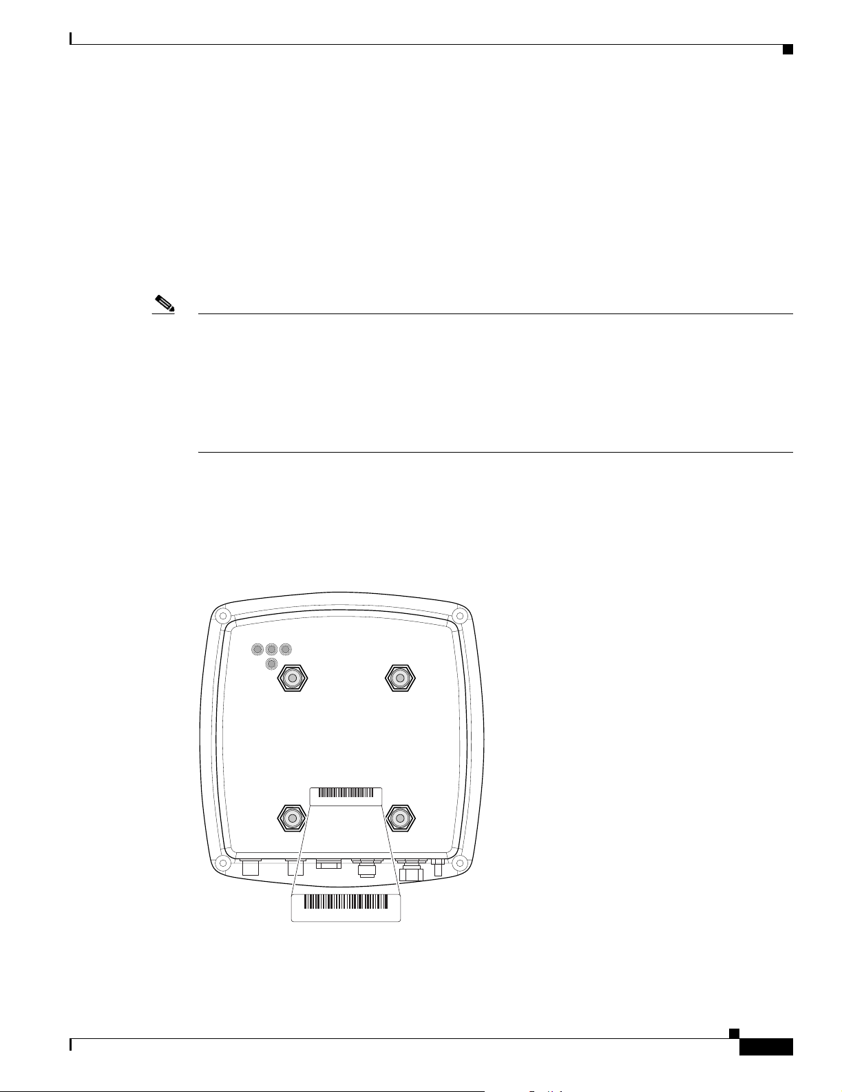
The access point/bridge serial number is located on the bottom of the cabinet (refer to Figure 1).
Figure 1 Location of Access Point/Bridge Serial Number Label
RSIE
SN: AAANNNNXXXX
OL-5048-02
SN: AAANNNNXXXX
Cisco Aironet 1300 Series Outdoor Access Point/Bridge Hardware Installation Guide
117062
xv
Page 16
Obtaining Technical Assistance
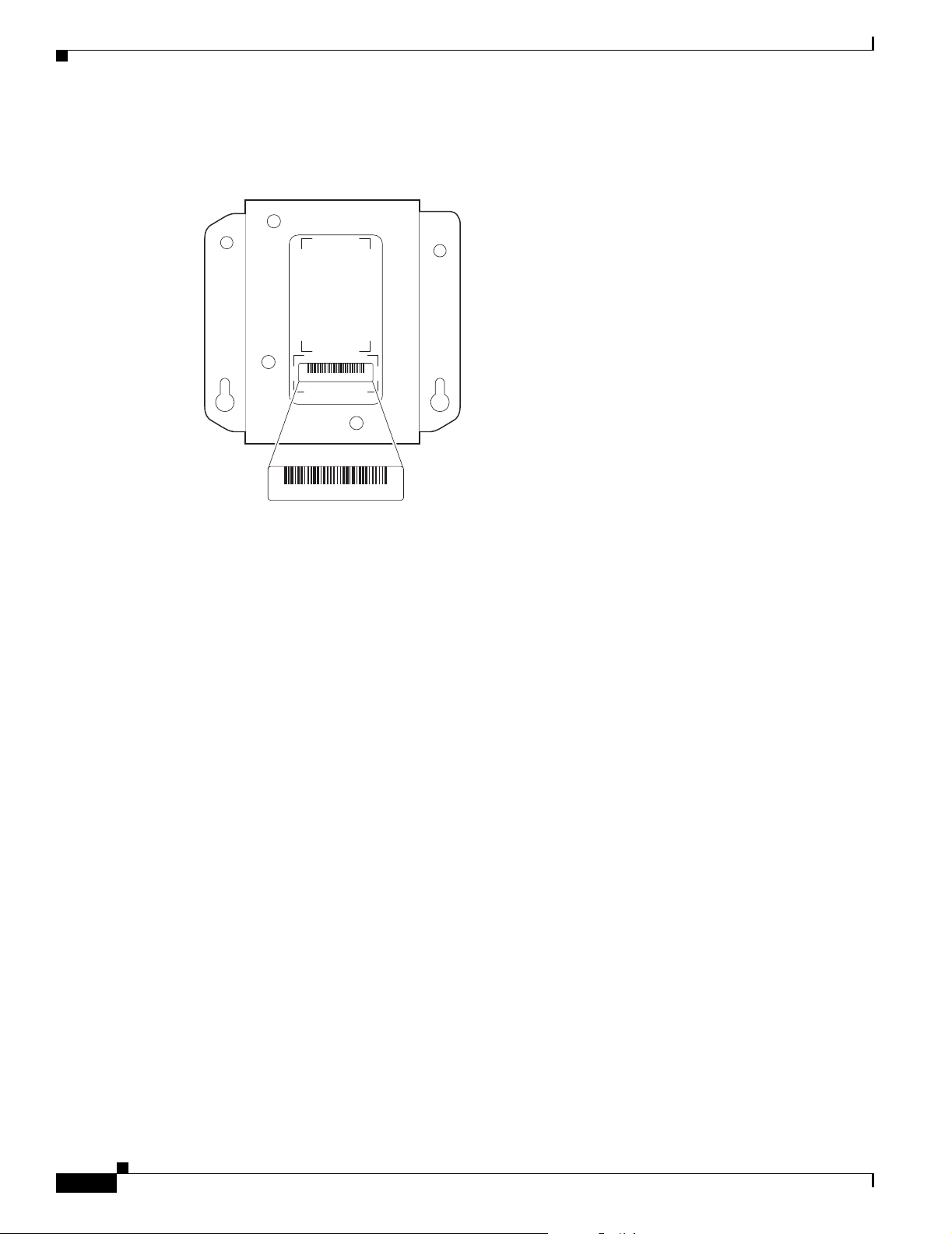
The power injector serial number is located on the bottom of the cabinet (refer to Figure 2).
Figure 2 Location of Power Injector Serial Number Label
Preface
SN: AAANNNNXXXX
SN: AAANNNNXXXX
The access point/bridge serial number label contains the following information:
• Model number, such as AIR-BR1300
• Serial number, such as S/N: VDF0636XXXX (11 alphanumeric digits)
• MAC address, such as MAC: 00abc65094f3 (12 hexadecimal digits)
• Location of manufacture, such as Made in Singapore
You need your product serial number when requesting support from the Cisco Technical Assistance
Center.
Submitting a Service Request
Using the online TAC Service Request Tool is the fastest way to open S3 and S4 service requests. (S3
and S4 service requests are those in which your network is minimally impaired or for which you require
product information.) After you describe your situation, the TAC Service Request Tool provides
recommended solutions. If your issue is not resolved using the recommended resources, your service
request is assigned to a Cisco TAC engineer. The TAC Service Request Tool is located at this URL:
http://www.cisco.com/techsupport/servicerequest
For S1 or S2 service requests or if you do not have Internet access, contact the Cisco TAC by telephone.
(S1 or S2 service requests are those in which your production network is down or severely degraded.)
Cisco TAC engineers are assigned immediately to S1 and S2 service requests to help keep your business
operations running smoothly.
To open a service request by telephone, use one of the following numbers:
117063
xvi
Asia-Pacific: +61 2 8446 7411 (Australia: 1 800 805 227)
EMEA: +32 2 704 55 55
USA: 1 800 553-2447
For a complete list of Cisco TAC contacts, go to this URL:
http://www.cisco.com/techsupport/contacts
Cisco Aironet 1300 Series Outdoor Access Point/Bridge Hardware Installation Guide
OL-5048-02
Page 17

Preface
Obtaining Additional Publications and Information
Definitions of Service Request Severity
To ensure that all service requests are reported in a standard format, Cisco has established severity
definitions.
Severity 1 (S1)—Your network is “down,” or there is a critical impact to your business operations. You
and Cisco will commit all necessary resources around the clock to resolve the situation.
Severity 2 (S2)—Operation of an existing network is severely degraded, or significant aspects of your
business operation are negatively affected by inadequate performance of Cisco products. You and Cisco
will commit full-time resources during normal business hours to resolve the situation.
Severity 3 (S3)—Operational performance of your network is impaired, but most business operations
remain functional. You and Cisco will commit resources during normal business hours to restore service
to satisfactory levels.
Severity 4 (S4)—You require information or assistance with Cisco product capabilities, installation, or
configuration. There is little or no effect on your business operations.
Obtaining Additional Publications and Information
Information about Cisco products, technologies, and network solutions is available from various online
and printed sources.
• Cisco Marketplace provides a variety of Cisco books, reference guides, and logo merchandise. Visit
Cisco Marketplace, the company store, at this URL:
http://www.cisco.com/go/marketplace/
• Cisco Press publishes a wide range of general networking, training and certification titles. Both new
and experienced users will benefit from these publications. For current Cisco Press titles and other
information, go to Cisco Press at this URL:
http://www.ciscopress.com
• Pack et magazine is the Cisco Systems technical user magazine for maximizing Internet and
networking investments. Each quarter, Packet delivers coverage of the latest industry trends,
technology breakthroughs, and Cisco products and solutions, as well as network deployment and
troubleshooting tips, configuration examples, customer case studies, certification and training
information, and links to scores of in-depth online resources. You can access Packet magazine at
this URL:
http://www.cisco.com/packet
• iQ Magazine is the quarterly publication from Cisco Systems designed to help growing companies
learn how they can use technology to increase revenue, streamline their business, and expand
services. The publication identifies the challenges facing these companies and the technologies to
help solve them, using real-world case studies and business strategies to help readers make sound
technology investment decisions. You can access iQ Magazine at this URL:
http://www.cisco.com/go/iqmagazine
• Internet Protocol Journal is a quarterly journal published by Cisco Systems for engineering
professionals involved in designing, developing, and operating public and private internets and
intranets. You can access the Internet Protocol Journal at this URL:
OL-5048-02
http://www.cisco.com/ipj
Cisco Aironet 1300 Series Outdoor Access Point/Bridge Hardware Installation Guide
xvii
Page 18

Obtaining Additional Publications and Information
• World-class networking training is available from Cisco. You can view current offerings at
this URL:
http://www.cisco.com/en/US/learning/index.html
Preface
xviii
Cisco Aironet 1300 Series Outdoor Access Point/Bridge Hardware Installation Guide
OL-5048-02
Page 19

CHA P TER
1
Overview
The Cisco Aironet 1300 Series Outdoor Access Point/Bridge (hereafter called the access point/bridge)
is a wireless device designed for building-to-building wireless connectivity. Operating in the 2.4-GHz
band (2.400 to 2.497 GHz), using the IEEE 802.11g standard, the access point/bridge delivers 1 to 54
Mbps data rates without the need for a license. The access point/bridge is a self-contained unit designed
for indoor or outdoor installations, providing differing antenna gains as well as coverage patterns. It
supports point-to-point and multipoint bridging configurations.
The access point/bridge can also be configured to operate as an access point or as a workgroup bridge.
When placed in access point mode, the unit supports wireless IEEE 802.11b and IEEE 802.11g client
devices. When placed into workgroup bridge mode, the unit provides a wireless connection for remote
wired devices to a Cisco Aironet access point or to a Cisco Aironet bridge.
The access point/bridge uses a browser-based management system, but you can also configure the access
point/bridge using Cisco IOS commands or Simple Network Management Protocol (SNMP).
This chapter provides information on the following topics:
• Key Features, page 1-2
• Network Configuration Examples, page 1-7
OL-5048-02
Cisco Aironet 1300 Series Outdoor Access Point/Bridge Hardware Installation Guide
1-1
Page 20
Key Features
Key Features
Key features of the access point/bridge:
• Unlicensed IEEE 802.11g 2.4-GHz radio operation
• Enclosure supports indoor or outdoor installations
• Integrated antenna or external antenna configurations (see Figure 1-1)
• Dual-coax 100-Mbps Ethernet ports
• Four LEDs
• Inline power over dual-coax cables
• Console serial interface on power injector
• Receive Signal Strength Indicator (RSSI) LED patterns for easy antenna alignment
• Control using Cisco IOS commands, Internet browser, SNMP, or serial interface (on power injector)
• Three operating modes:
–
Bridge mode
Chapter 1 Overview
–
Access point mode
–
Workgroup bridge mode
Figure 1-1 Access Point/Bridge Configurations
1
2
117059
1-2
1 Integrated antenna access point/bridge
2 External antenna access point/bridge
configuration
Cisco Aironet 1300 Series Outdoor Access Point/Bridge Hardware Installation Guide
configuration with external antenna
connectors
OL-5048-02
Page 21

Chapter 1 Overview
Power
Key Features
Note Antenna connectors are available only on the external antenna access point/bridge configuration.
The access point/bridge receives inline power from the Cisco Aironet Power Injector (hereafter called
the power injector). Dual-coax cables are used to provide Ethernet data and power from the power
injector to the access point/bridge. The power injector is an external unit designed for operation in a
sheltered environment, such as inside a building or vehicle. The power injector also functions as an
Ethernet repeater by connecting to a Category 5 LAN backbone and using the dual-coax cable interface
to the access point/bridge.
The power injector is available in two models:
• Cisco Aironet Power Injector LR2—standard version (included with the bridge)
–
48-VDC input power
–
Uses the 48-VDC power module (included with the bridge)
• Cisco Aironet Power Injector LR2T—optional transportation version
–
–
Note The power injector and the power module should not be placed in an outdoor unprotected environment.
The power module should not be placed in a building’s environmental air space, such as above a suspended
ceiling.
Integrated Antenna
The access point/bridge is available with an integrated 13-dBi patch array antenna. The antenna is
covered with a radome to protect it from environmental elements. The integrated antenna is vertically
polarized.
Note Some international regulatory regions may restrict the integrated antenna access point/bridge
configuration.
12- to 40-VDC input power
DC power supplied from a vehicle battery
OL-5048-02
Cisco Aironet 1300 Series Outdoor Access Point/Bridge Hardware Installation Guide
1-3
Page 22

Key Features
External Antenna
The access point/bridge is available in an external antenna configuration (see Figure 1-1) for use with
Cisco Aironet 2.4-GHz antennas. Two reverse-TNC type RF connectors are provided on the end of the
unit to support single or diversity antenna configurations.
The antennas connect to the access point/bridge antenna connectors using a coax cable. These are some
of the external antennas supported by the access point/bridge:
• 5.2-dBi omnidirectional antenna with vertical polarization
• 12-dBi omnidirectional antenna with vertical polarization
• 9-dBi patch wall mount antenna
• 10-dBi yagi antenna
• 13.5-dBi yagi antenna
• 14-dBi sector antenna with vertical polarization
• 21-dBi dish antenna
Chapter 1 Overview
Note To meet regulatory restrictions, the external antenna access point/bridge unit and the external antenna
Ethernet Ports
Enclosure
Connectors
must be professionally installed. The network administrator or other IT professional responsible for
installing and configuring the unit is a suitable professional installer. Following installation, access to the
unit should be password protected by the network administrator to maintain regulatory compliance.
The access point/bridge dual-coax Ethernet ports consists of a pair of 75-ohm F-type connectors, linking
the unit to your 100BASE-T Ethernet LAN through the power injector. The dual-coax cables are used to
send and receive Ethernet data and to supply inline 48-VDC power from the power injector to the access
point/bridge. For the location of the ports, refer to Figure 1-3.
The access point/bridge uses an enclosure that supports indoor or outdoor operating environments. (refer
to “Access Point/Bridge Specifications” section on page C-1).
The connectors (see Figure 1-2) provided depend upon the access point/bridge configuration:
1-4
• Integrated antenna access point/bridge configuration
–
Dual-coax Ethernet connectors—used to provide Ethernet signals and in-line power
• External antenna access point/bridge configuration
–
Dual-coax Ethernet connectors—used to provide Ethernet signals and in-line power
–
Dual antenna connectors—used to support a single antenna or dual-diversity antennas
Cisco Aironet 1300 Series Outdoor Access Point/Bridge Hardware Installation Guide
OL-5048-02
Page 23
Chapter 1 Overview
Key Features
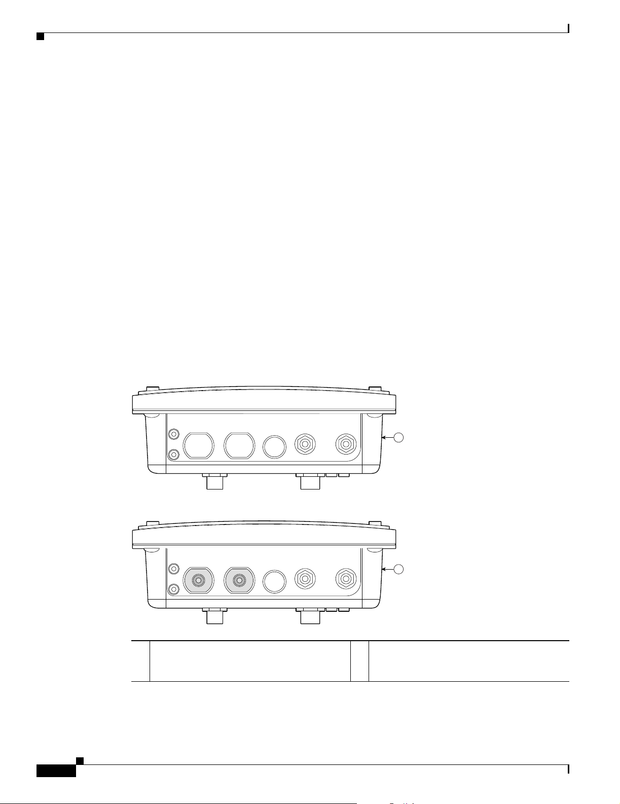
Figure 1-2 Access Point/Bridge Connector Locations
LEDs
1
2
3
4
117060
5
1 Ground lug mounting screws 3 Mounting posts
2 Left antenna connector (external antenna
4 LEDs
access point/bridge configuration only)
Primary right antenna connector (external
5 Dual-coax Ethernet ports (F-Type connectors)
antenna access point/bridge configuration
only)
Four LEDs are located on back of the housing to report installation and alignment conditions, status,
radio activity, and Ethernet activity (see Figure 1-3).
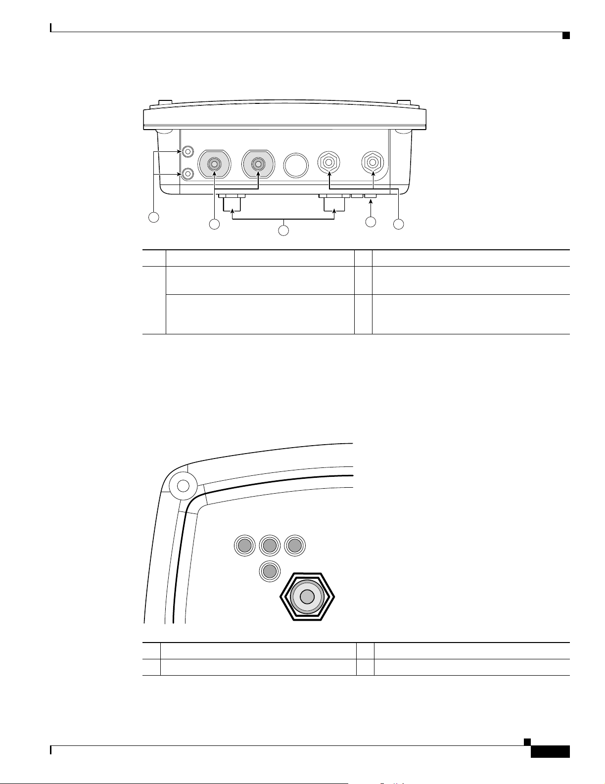
Figure 1-3 LEDs
OL-5048-02
RSIE
117061
R Radio LED (R) E Ethernet LED (E)
S Status LED (S) I Install LED (I)
Cisco Aironet 1300 Series Outdoor Access Point/Bridge Hardware Installation Guide
1-5
Page 24

Key Features
• The install LED indicates that installation mode is activated. During installation mode, the other
• The radio LED blinks green to indicate radio traffic activity. The light is normally off, but it blinks
• The status LED indicates association status. Blinking green indicates that the access point/bridge is
• The Ethernet LED indicates Ethernet traffic. This LED blinks green when a packet is received or
For additional information on the LEDs, refer to “Checking the LEDs” section on page 7-2.
Operating Roles
The access point/bridge can be configured into one of five operating roles:
Chapter 1 Overview
LEDs provide signal strength readings used for antenna alignment.
green whenever a packet is received or transmitted over the radio link. This LED also provides signal
strength readings during installation mode.
not associated with another bridge. Steady green indicates that the unit is associated with at least
one other bridge. This LED also provides signal strength readings during installation mode.
transmitted over the Ethernet infrastructure. The LED is off when the Ethernet link not working or
the port is shutdown. This LED also provides signal strength readings during installation mode.
–
Install Mode—Activates the bridge install and alignment mode. Specifies that the unit
automatically determines the network role. If the unit is able to associate to another Cisco
Aironet root bridge within 60 seconds, the unit assumes a non-root bridge role. If the unit is
unable to associate with another Cisco Aironet root bridge within 60 seconds, the unit assumes
a root bridge role.
You can also pre-configure the access point/bridge into root bridge or non-root bridge modes
and avoid the 60-second automatic detection phase.
–
Root—Specifies that the access point/bridge is operating as a root bridge and connects directly
to the main Ethernet LAN network. In this mode, the unit accepts associations from other Cisco
Aironet bridges and wireless client devices.
–
Non-root—Specifies that the access point/bridge is operating as a non-root bridge, and that it
connects to a remote LAN network, and that it must associate with a Cisco Aironet root bridge
using the wireless interface.
–
Root Access Point—Specifies that the access point/bridge operates as an access point
connected to the main Ethernet LAN network. In this mode, wireless client devices are allowed
to associate to the unit.
–
Workgroup Bridge—Specifies that the access point/bridge operates as a workgroup bridge
connected to a small wired Ethernet LAN network through an Ethernet hub or switch. The
workgroup bridge must associate to a Cisco Aironet access point or a Cisco Aironet bridge.
Note On initial power up, an access point/bridge running Cisco IOS Release 12.3(2)JA2 and earlier
defaults to the Install-Mode role. On initial power up, an access point/bridge running Cisco IOS
Release 12.3(4)JA defaults to the Root AP role.
1-6
Refer to the Cisco IOS Software Configuration Guide for Cisco Aironet Bridges and to the Cisco IOS
Software Configuration Guide for Cisco Aironet Access Points for additional information on the
operating modes supported by the access point/bridge.
Cisco Aironet 1300 Series Outdoor Access Point/Bridge Hardware Installation Guide
OL-5048-02
Page 25

Chapter 1 Overview
Network Configuration Examples
This section describes the access point/bridge’s role in five common wireless network configurations.
Point-to-Point Bridge Configuration
In a point-to-point bridge configuration, two bridges connect two remote LAN networks using a wireless
communication link (see Figure 1-4). The bridge connected to the main LAN network is classified as a
root bridge and the other bridge is classified as a non-root bridge.
Figure 1-4 Point-to-Point Bridge Configuration
Network Configuration Examples
117029
Port Aggregation or Redundancy Bridge Configuration
The port aggregation or redundancy bridge configuration (Figure 1-5) is used to provide increased
bandwidth or backup redundancy communications between two LANs. Port aggregation or increased
bandwidth occurs when both wireless links are used to simultaneously pass Ethernet traffic. Backup
communication redundancy can be achieved with this configuration when one wireless bridge link is
used only if the other wireless bridge link fails.
Figure 1-5 Port Aggregation or Redundancy Bridge Configuration
117020
OL-5048-02
Cisco Aironet 1300 Series Outdoor Access Point/Bridge Hardware Installation Guide
1-7
Page 26
Network Configuration Examples
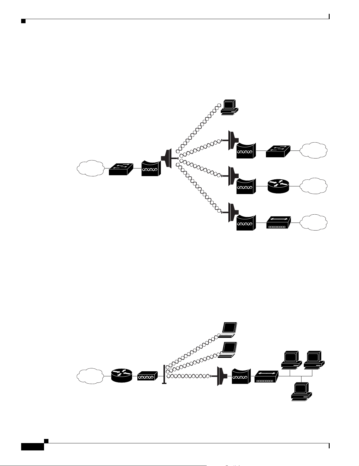
Point-to-Multipoint Bridge Configuration
The point-to-multipoint bridge configuration (Figure 1-6) connects the main LAN network to multiple
remote LAN networks. Wireless devices can also connect to the root bridge.
Figure 1-6 Point-to-Multipoint Bridge Configuration
Chapter 1 Overview
Access Point Configuration
When configured in access point mode, the unit can support remote workgroup bridges and local
wireless client devices (see Figure 1-7). The access point/bridge defaults to a root access point role.
Figure 1-7 Access Point Configuration
The access point configuration allows the wireless devices and the Ethernet-enabled wired devices using
the workgroup bridge to pass Ethernet traffic to and from the main LAN.
Access
point
Workgroup
bridge
117021
117075
1-8
Cisco Aironet 1300 Series Outdoor Access Point/Bridge Hardware Installation Guide
OL-5048-02
Page 27

Chapter 1 Overview
Workgroup Bridge Configuration
When configured in the workgroup bridge mode, the unit provides a wireless connection for remote
wired devices to a Cisco Aironet access point (see Figure 1-8) or to a Cisco Aironet bridge (see
Figure 1-9).
Figure 1-8 Workgroup Bridge Configuration 1
Network Configuration Examples
Access
point
Workgroup
bridge
In Figure 1-8, the unit is configured in workgroup bridge mode and is associated to a Cisco Aironet
access point as a wireless client device. This configuration allows the Ethernet-enabled devices to pass
Ethernet traffic to and from the main LAN using the workgroup bridge.
Figure 1-9 Workgroup Bridge Configuration 2
Bridge Workgroup
bridge
In Figure 1-9, the unit is configured in workgroup bridge mode and is associated to a Cisco Aironet root
bridge as a wireless bridge device. This configuration allows the Ethernet-enabled devices pass Ethernet
traffic to and from the main LAN using the workgroup bridge. The main advantage of this configuration
is that the wireless communication link can be over a longer distance than an access point supports.
Typically, an access point can communicate over approximately a 1-mile range; however, the
bridge-to-bridge wireless link can communicate over approximately a 21-mile range.
117076
117077
OL-5048-02
Cisco Aironet 1300 Series Outdoor Access Point/Bridge Hardware Installation Guide
1-9
Page 28

Network Configuration Examples
Chapter 1 Overview
1-10
Cisco Aironet 1300 Series Outdoor Access Point/Bridge Hardware Installation Guide
OL-5048-02
Page 29

CHA P TER
2
Installation Overview
This chapter provides warnings, safety information, and information needed before you begin the
installation of your access point/bridge system. This chapter includes the following sections:
• Safety Warnings, page 2-2
• Safety Information, page 2-3
• Unpacking the Access Point/Bridge, page 2-6
• Before Beginning the Installation, page 2-7
• Installation Summary, page 2-9
OL-5048-02
Cisco Aironet 1300 Series Outdoor Access Point/Bridge Hardware Installation Guide
2-1
Page 30

Safety Warnings
Safety Warnings
Translated versions of the following safety warnings are provided in Appendix A, “Translated Safety
Warnings.”
All Installations
Chapter 2 Installation Overview
Warning
Warning
Warning
Warning
Warning
This warning symbol means danger. You are in a situation that could cause bodily injury. Before
you work on any equipment, be aware of the hazards involved with electrical circuitry and be
familiar with standard practices for preventing accidents. (To see translations of the warnings
that appear in this publication, refer to the appendix “Translated Safety Warnings.”)
Do not operate your wireless network device near unshielded blasting caps or in an explosive
environment unless the device has been modified to be especially qualified for such use.
Statement 245B
In order to comply with international radio frequency (RF) exposure limits, dish antennas should be
placed at a minimum of 8.7 inches (22 cm) from the bodies of all persons. Other antennas should be
placed a minimum of 7.9 inches (20 cm) from the bodies of all persons.
Do not work on the system or connect or disconnect cables during periods of lightning activity.
Statement 1001
This product relies on the building’s installation for short-circuit (overcurrent) protection. Ensure that
the protective device is rated not greater than: 15A
Statement 1005
Statement 346
Statement 84
2-2
Warning
Warning
Cisco Aironet 1300 Series Outdoor Access Point/Bridge Hardware Installation Guide
This equipment must be grounded. Never defeat the ground conductor or operate the equipment in the
absence of a suitably installed ground conductor. Contact the appropriate electrical inspection
authority or an electrician if you are uncertain that suitable grounding is available.
Ultimate disposal of this product should be handled according to all national laws and regulations.
Statement 1040
Statement 1024
OL-5048-02
Page 31

Chapter 2 Installation Overview
Safety Information
Warning
Do not locate the antenna near overhead power lines or other electric light or power circuits, or
where it can come into contact with such circuits. When installing the antenna, take extreme care
not to come into contact with such circuits, as they may cause serious injury or death. For proper
installation and grounding of the antenna, please refer to national and local codes (e.g. U.S.:NFPA 70,
National Electrical Code, Article 810, in Canada: Canadian Electrical Code, Section 54).
Statement 1052
Outdoor and Vehicle Installations
The following warning applies to outdoor and vehicle installations:
Warning
Only trained and qualified personnel should be allowed to install, replace, or service this equipment.
Statement 1030
Vehicle Bridge Installations
The following warnings apply to vehicle bridge installations:
Warning
A readily accessible two-poled disconnect device must be incorporated in the fixed wiring.
Statement 1022
Warning
Connect the unit only to DC power source that complies with the safety extra-low voltage (SELV)
requirements in IEC 60950 based safety standards.
Safety Information
Follow the guidelines in this section to ensure proper operation and safe use of the access point/bridge.
FCC Safety Compliance Statement
The FCC, with its action in ET Docket 96-8, has adopted a safety standard for human exposure to RF
electromagnetic energy emitted by FCC-certified equipment. When used with approved Cisco Aironet
antennas, Cisco Aironet products meet the uncontrolled environmental limits found in OET-65 and ANSI
C95.1, 1991. Proper operation of this radio device according to the instructions in this publication results
in user exposure substantially below the FCC recommended limits.
Statement 1033
OL-5048-02
Cisco Aironet 1300 Series Outdoor Access Point/Bridge Hardware Installation Guide
2-3
Page 32

Safety Information
Safety Precautions
Chapter 2 Installation Overview
Warning
Do not locate the antenna near overhead power lines or other electric light or power circuits, or
where it can come into contact with such circuits. When installing the antenna, take extreme care
not to come into contact with such circuits, as they may cause serious injury or death. For proper
installation and grounding of the antenna, please refer to national and local codes (e.g. U.S.:NFPA 70,
National Electrical Code, Article 810, in Canada: Canadian Electrical Code, Section 54).
Statement 1052
Each year hundreds of people are killed or injured when attempting to install an antenna. In many of
these cases, the victim was aware of the danger of electrocution, but did not take adequate steps to avoid
the hazard.
For your safety, and to help you achieve a good installation, please read and follow these safety
precautions. They may save your life!
1. If you are installing an antenna for the first time, for your own safety as well as others, seek
professional assistance.
2. Select your installation site with safety, as well as performance in mind. Remember: electric power
lines and phone lines look alike. For your safety, assume that any overhead line can kill you.
3. Call your electric power company. Tell them your plans and ask them to come look at your proposed
installation. This is a small inconvenience considering your life is at stake.
4. Plan your installation carefully and completely before you begin. Successful raising of a mast or
tower is largely a matter of coordination. Each person should be assigned to a specific task, and
should know what to do and when to do it. One person should be in charge of the operation to issue
instructions and watch for signs of trouble.
5. When installing your antenna, remember:
a. Do not use a metal ladder.
2-4
b. Do not work on a wet or windy day.
c. Do dress properly—shoes with rubber soles and heels, rubber gloves, long sleeved shirt or
jacket.
6. If the assembly starts to drop, get away from it and let it fall. Remember, the antenna, mast, cable,
and metal guy wires are all excellent conductors of electrical current. Even the slightest touch of any
of these parts to a power line complete an electrical path through the antenna and the installer: you!
7. If any part of the antenna system should come in contact with a power line, don’t touch it or try to
remove it yourself. Call your local power company. They will remove it safely.
If an accident should occur with the power lines call for qualified emergency help immediately.
Cisco Aironet 1300 Series Outdoor Access Point/Bridge Hardware Installation Guide
OL-5048-02
Page 33
Chapter 2 Installation Overview
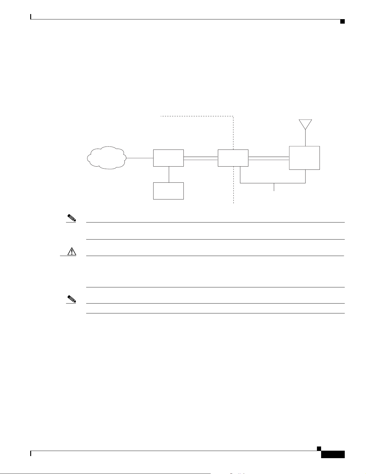
Typical Outdoor Installation Components
The access point/bridge is designed to be installed in an outdoor environment, typically on a tower or a
tall building. A typical installation diagram is shown in Figure 2-1.
Figure 2-1 Typical Outdoor Installation Diagram
Installation Guidelines
Building
entrance
Indoor
Category 5
Ethernet
LAN network
Note Ground wires must comply with Sections 810 and 820 of the National Electrical Code and Section 54 of
cable
Power
injector
Power
module
Dual-coax
cables
Grounding
block
Outdoor
Dual-coax
cables
Ground
(see note)
Integrated
or
external antenna
Bridge
88836
the Canadian Electrical Code.
Caution To ensure correct installation and grounding, install the access point/bridge in compliance with your
local and national electrical codes: National Fire Protection Association (NFPA) 70, National Electrical
Code (U.S.); Canadian Electrical Code, Part I, CSA 22.1 (Canada); and if local or national electrical
codes are not available, refer to IEC 364, Part 1 through 7 (other countries).
Note The grounding block is not required for indoor installations of the access point/bridge.
Installation Guidelines
Because the access point/bridge is a radio device, it is susceptible to common causes of interference that
can reduce throughput and range. Follow these basic guidelines to ensure the best possible performance:
• Install the access point/bridge in an area where structures, trees, or hills do not obstruct radio signals
to and from the unit.
• Install the access point/bridge at a height sufficient to provide a clear line-of-sight signal path.
OL-5048-02
Cisco Aironet 1300 Series Outdoor Access Point/Bridge Hardware Installation Guide
2-5
Page 34

Site Surveys
Site Surveys
Every network application is a unique installation. Before installing multiple access point/bridges, you
should perform a site survey to determine the optimum use of networking components and to maximize
range, coverage, and network performance.
Consider the following operating and environmental conditions when performing a site survey:
Chapter 2 Installation Overview
• Data rates—Sensitivity and range are inversely proportional to data bit rates. The maximum radio
range is achieved at the lowest workable data rate. A decrease in receiver sensitivity occurs as the
radio data increases.
• Antenna type and placement—Proper antenna configuration is a critical factor in maximizing radio
range. As a general rule, range increases in proportion to antenna height. However, do not place the
antenna higher than necessary because the extra height also increases potential interference from
other unlicensed radio systems.
• Physical environment—Clear or open areas provide better radio range than closed or filled areas.
• Obstructions—Physical obstructions such as buildings, trees, or hills can hinder performance of
wireless devices. Avoid locating the devices in a location where there is an obstruction between the
sending and receiving antennas.
Unpacking the Access Point/Bridge
Follow these steps to unpack the access point/bridge:
Step 1 Open the shipping container and carefully remove the contents.
Step 2 Return all packing materials to the shipping container and save it.
Step 3 Ensure that all items listed in the “Package Contents” section are included in the shipment. If any item
is damaged or missing, notify your authorized Cisco sales representative.
Package Contents
Each access point/bridge package contains these items:
• Access point/bridge unit (integrated antenna or external antenna configuration)
• Power injector (LR2) unit (with mounting screws and wall anchors)
• Power module and AC power cord
• Quick Start Guide: Cisco Aironet 1300 Series Outdoor Access Point/Bridge
• Cisco Aironet 1300 Series Outdoor Access Point/Bridge Mounting Instructions
• Cisco product registration and Cisco documentation feedback cards
2-6
Cisco Aironet 1300 Series Outdoor Access Point/Bridge Hardware Installation Guide
OL-5048-02
Page 35

Chapter 2 Installation Overview
The optional roof mount kit contains these items:
• One roof-wall mount
• Two dual-coax cables [20 ft (6.1 m) and 50 ft (15.2 m)]
• Multi-function mount (consisting of a access point/bridge bracket and a mast bracket)
• Two tower clamps (U-bolts) with four nuts and washers
• Four bolts and washers for securing the access point/bridge bracket to the mast bracket
• Four bolts for securing the access point/bridge bracket to the unit
• Grounding block and mounting screws
• Ground lug for the access point/bridge, two hex nuts, and two washers
• Weatherproofing kit (consisting of Coax Seal and electrical joint compound)
The optional wall mount kit (for indoor use) contains these items:
• Wall mount bracket with 4 mounting bolts and washers
• Two sub-mini RG-59 coax cables (12 in. or 30.5 cm)
The optional power injector for transportation vehicles
Before Beginning the Installation
• Power injector (LR2T) unit
Before Beginning the Installation
Before you begin the installation process, please carefully review the following list of figures to become
familiar with the system components, connectors, indicators, cables, system interconnection, and
grounding:
• Installation diagram (Figure 2-1)
• Bridge layout (Figure 2-2)
• Power injector layout (Figure 2-3)
• Power module (Figure 2-4)
• Grounding block (Figure 2-5)
Note To meet regulatory restrictions, the external antenna access point/bridge unit and the external antenna
must be professionally installed. The network administration or other IT professional responsible for
installing and configuring the unit is a suitable professional installer. Following installation, access to the
unit should be password protected by the network administrator to maintain regulatory compliance.
OL-5048-02
Cisco Aironet 1300 Series Outdoor Access Point/Bridge Hardware Installation Guide
2-7
Page 36
Before Beginning the Installation
Figure 2-2 Access Point/Bridge Layout
Chapter 2 Installation Overview
1
2
4
5
117060
3
1 Grounding studs 4 LEDs
2 Antenna connectors 5 Dual-coax Ethernet ports (F-Type connectors)
3 Mounting lugs
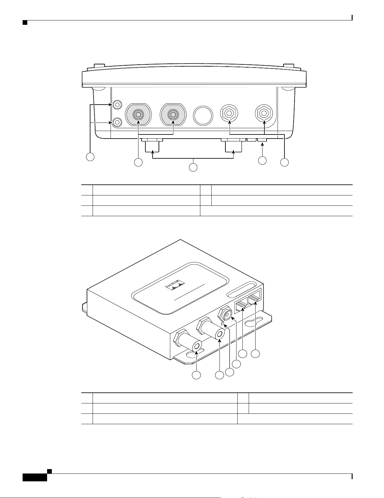
Figure 2-3 Power Injector Indicators and Connectors
POWER INJECTOR
CISCO AIRONET
117189
2-8
11
1 Dual-coax Ethernet ports (F-Type connectors) 4 Ethernet LAN port (RJ-45 connector)
2 Power LED 5 Console serial port (RJ-45 connector)
3 Power jack
Cisco Aironet 1300 Series Outdoor Access Point/Bridge Hardware Installation Guide
54
3
2
OL-5048-02
Page 37
Chapter 2 Installation Overview
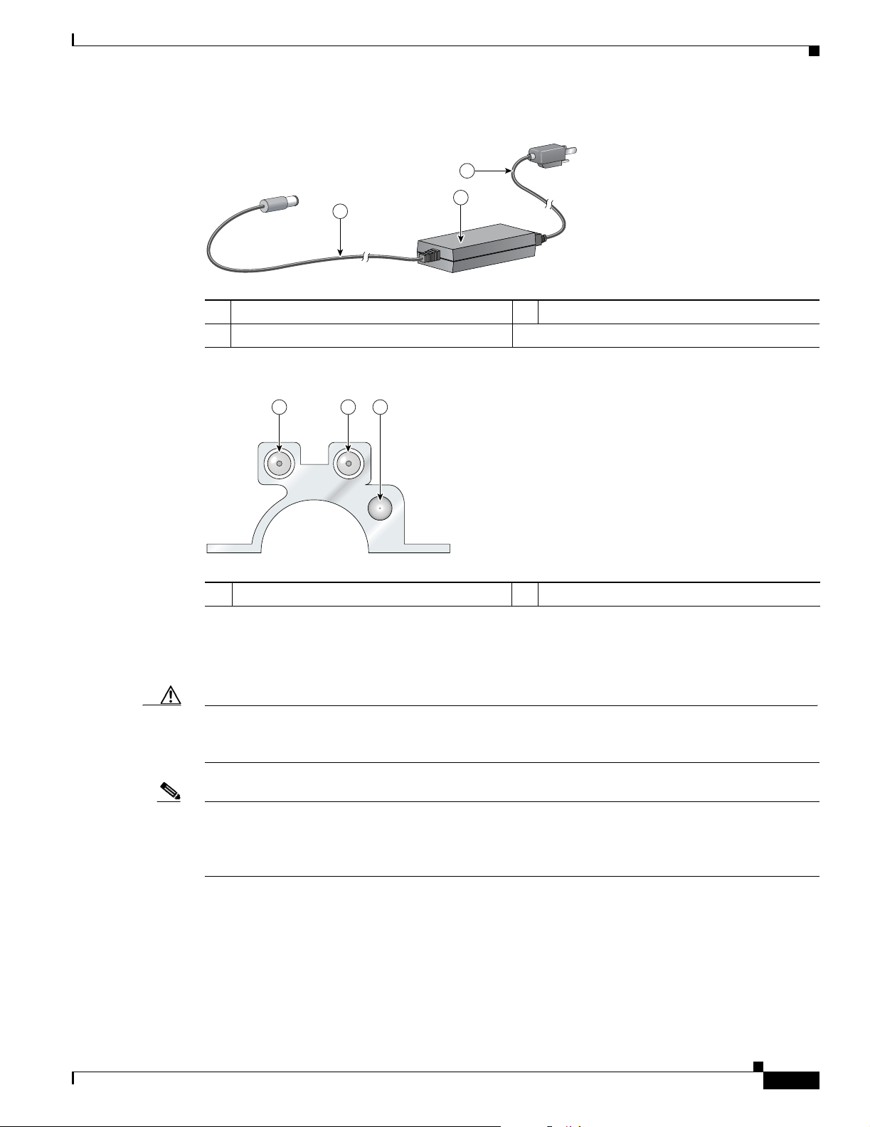
Figure 2-4 Power Module
Installation Summary
3
1
2
88829
1 48-VDC power output cable 3 AC power cord
2 Power module
Figure 2-5 Grounding Block
1 1 2
88830
1 F-type coaxial connectors 2 Ground wire lug
Installation Summary
Caution You should read and carefully follow the installation instructions before connecing the system to its
power source. The access point/bridge and power injector can be damaged by incorrect power
application.
Note To meet regulatory restrictions, the external antenna access point/bridge unit and the external antenna
must be professionally installed. The network administrator or other IT professional responsible for
installing and configuring the unit is a suitable professional installer. Following installation, access to the
unit should be password protected by the network administrator to maintain regulatory compliance.
During the installation of the access point/bridge, you will perform the following operations:
• Connect a user-supplied Category 5 Ethernet cable from your wired LAN network to the power
injector.
OL-5048-02
Cisco Aironet 1300 Series Outdoor Access Point/Bridge Hardware Installation Guide
2-9
Page 38

Installation Summary
Chapter 2 Installation Overview
• For outdoor installations, connect the dual-coax Ethernet cables between the power injector and the
grounding block. For indoor installations, connect the dual-coax cables to the power injector.
Tip You can connect the dual-coax cable connectors to either of the grounding block connectors or
the power injector’s dual-coax Ethernet ports. The access point/bridge senses the Ethernet
signals and automatically switches internal circuitry to match the cable connections.
Note You should securely tighten the cable connectors (15 to 20 inch-pounds) using a small wrench.
• For outdoor installations, connect a ground wire to the grounding block.
• Mount the access point/bridge to the mast, tower, or wall. For additional information, refer to the
Cisco Aironet 1300 Series Outdoor Access Point/Bridge Mounting Instructions that shipped with
your access point/bridge.
Warning
Warning
This equipment must be grounded. Never defeat the ground conductor or operate the equipment in the
absence of a suitably installed ground conductor. Contact the appropriate electrical inspection
authority or an electrician if you are uncertain that suitable grounding is available.
• Connect a ground wire to the access point/bridge (use the access point/bridge ground lug).
• For outdoor installations, connect the dual-coax Ethernet cables to the grounding block and to the
Statement 1024
access point/bridge. For indoor installations, connect the dual-coax cables directly to the access
point/bridge.
Tip You can connect the dual-coax cable connectors to either of the grounding block connectors or
the access point/bridge’s dual-coax ports. The access point/bridge senses the Ethernet signals
and automatically switches internal circuitry to match the cable connections.
Note You should securely tighten the cable connectors (15 to 20 inch-pounds) using a small wrench.
This product relies on the building’s installation for short-circuit (overcurrent) protection. Ensure that
the protective device is rated not greater than: 15A
• For indoor installations, connect these items:
–
The AC power cord to the 48-VDC power module.
Statement 1005
2-10
–
The power module power plug to the power injector and plug the AC cord into an AC power
receptacle.
• For bridge installations, align the antennas. For additional information, refer to the Cisco Aironet
1300 Series Outdoor Access Point/Bridge Mounting Instructions that shipped with your access
point/bridge.
• Configure basic settings (refer to Chapter 5, “Configuring the Access Point/Bridge for the First
Time”).
Cisco Aironet 1300 Series Outdoor Access Point/Bridge Hardware Installation Guide
OL-5048-02
Page 39

Chapter 2 Installation Overview
• Seal all external connectors with special weather sealing material.
Configure security and other access point/bridge options. For additional information, refer to the Cisco
IOS Software Configuration Guide for Cisco Aironet Bridges or to the Cisco IOS Software Configuration
Guide for Cisco Aironet Access Points.
Installation Summary
OL-5048-02
Cisco Aironet 1300 Series Outdoor Access Point/Bridge Hardware Installation Guide
2-11
Page 40

Installation Summary
Chapter 2 Installation Overview
2-12
Cisco Aironet 1300 Series Outdoor Access Point/Bridge Hardware Installation Guide
OL-5048-02
Page 41

CHA P TER
3
Mounting and Alignment Overview
This chapter provides an overview of the access point/bridge mounting and bridge antenna alignment.
The following sections are included in this chapter:
• Mounting the Access Point/Bridge, page 3-2
• Mounting Hardware, page 3-2
• LEDs, page 3-5
• Aligning the Bridge Antenna Using RSSI LED Indications, page 3-7
OL-5048-02
Cisco Aironet 1300 Series Outdoor Access Point/Bridge Hardware Installation Guide
3-1
Page 42

Mounting the Access Point/Bridge
Mounting the Access Point/Bridge
Typically, the access point/bridge is installed on a rooftop, mast, tower, wall, or a suitable flat surface.
Each of these installations requires a different approach. This document provides a mounting overview.
For detailed mounting instructions, refer to the Cisco Aironet 1300 Series Outdoor Access Point/Bridge
Mounting Instructions that shipped with your unit.
The access point/bridge is available in two configurations:
• Integrated antenna access point/bridge (with 13-dBi)
• External antenna access point/bridge (with two antenna connectors for use with a single antenna or
dual diversity antennas)
Note Personnel installing the bridge must understand wireless bridging techniques, antenna alignment and
adjustment, and grounding methods.
Note To meet regulatory restrictions, the external antenna access point/bridge unit and the external antenna
must be professionally installed. The network administration or other IT professional responsible for
installing and configuring the unit is a suitable professional installer. Following installation, access to the
unit should be password protected by the network administrator to maintain regulatory compliance.
Chapter 3 Mounting and Alignment Overview
The following warning applies to outdoor and vehicle installations:
Warning
Only trained and qualified personnel should be allowed to install, replace, or service this equipment.
Statement 1030
Mounting Hardware
The access point/bridge supports the following optional mounting kits:
• The roof mount kit (for indoor or outdoor use) contains these items:
–
One roof-wall mount
–
Two dual-coax cables [20 ft (6.1 m) and 50 ft (15.2 m)]
–
Multi-function mount (consisting of a access point/bridge bracket and a mast bracket)
–
Two tower clamps (U-bolts) with four nuts and washers
–
Four bolts and washers for securing the access point/bridge bracket to the mast bracket
–
Four bolts for securing the access point/bridge bracket to the unit
–
Grounding block and mounting screws
–
Ground lug for the access point/bridge, two hex nuts, and two washers
–
Weatherproofing kit (consisting of Coax Seal and electrical joint compound)
• The wall mount kit (for indoor use) contains these items:
3-2
–
Wall mount bracket with 4 mounting bolts and washers
–
Two sub-mini RG-59 cables (12 in. or 30.5 cm)
Cisco Aironet 1300 Series Outdoor Access Point/Bridge Hardware Installation Guide
OL-5048-02
Page 43

Chapter 3 Mounting and Alignment Overview
Window Mounting
When a wireless link is deployed through a window, significant signal loss can be introduced by the
window. Typical losses range from 5 to15 dB per window, depending upon the type of glass. You should
take this extra loss into account when planning antenna gains and power settings. A thorough site survey
is critical for deployments through windows.
For additional information on a window mounting bracket, refer to the following URL:
http://www.terrawave.com/BR1300
Multi-Function Mount
The multi-function mount provides a method for mounting the access point/bridge on a mast, tower, or
a roof mount and consists of two parts (see Figure 3-1):
• Access point/bridge bracket—attaches to the back of the unit
• Mast bracket—attaches to the mast, tower, or roof mount
The multi-function mount permits easy azimuth and elevation adjustments for bridge antenna alignment.
The basic mounting procedure is shown below:
1. Mount the access point/bridge bracket to the mounting lugs on the access point/bridge.
Mounting Hardware
2. Mount the mast bracket to the tower or mast using the supplied U-bolts or appropriately sized
user-supplied U-bolts.
3. Suspend the access point/bridge on the mast bracket using the support pins.
4. Secure the access point/bridge bracket to the mast bracket using the supplied nuts, bolts, and
washers (hand tighten).
5. Connect the dual-coax cable to the power injector dual-coax Ethernet ports (F-type connectors) on
the access point/bridge.
Note You should securely tighten the cable connectors (15 to 20 inch-pounds) using a small wrench.
6. Connect the ground wire to the outdoor mounted access point/bridge using the supplied ground lug.
7. Connect the power cable to the power injector.
8. For bridge installations, align the antenna.
9. Tighten the nuts and bolts.
OL-5048-02
Cisco Aironet 1300 Series Outdoor Access Point/Bridge Hardware Installation Guide
3-3
Page 44

Mounting Hardware
Chapter 3 Mounting and Alignment Overview
Figure 3-1 Multi-Function Mount
2
1 Access point/bridge bracket with support pins 2 Mast bracket
Access Point/Bridge Bracket
The access point/bridge bracket mounts on the back side of the unit housing. The bracket mounts on four
lugs on the unit. The bracket contains two support pins that are used to suspend the unit in the notches
on the mast mounting bracket until you secure the mounting bolts.
The access point/bridge must be positioned to obtain the correct antenna polarization that matches the
remote antenna. The integrated access point/bridge antenna is vertically polarized. All access
point/bridges must use the same antenna polarization for best operation.
Mast Bracket
The mast bracket attaches to a mast or tower support and is used to secure the access point/bridge (see
Table 3-1).
Table 3-1 Mast Bracket Attachment Methods
Mast Type Mast Diameter Mast Attachment Method
Roof mount,
small mast, or tower
1
1.5 to 2.75 in.
(30.5 to 69.9 mm)
117119
Attach the pipe inside the mounting bracket,
between the bracket and access point/bridge.
3-4
Note The U-bolts provided with the roof mounting kit support mast diameters up to 1.75 in. (44.5 mm). For
larger masts, you must supply the U-bolts to attach the access point/bridge.
Cisco Aironet 1300 Series Outdoor Access Point/Bridge Hardware Installation Guide
OL-5048-02
Page 45

Chapter 3 Mounting and Alignment Overview
LEDs
The LEDs indicate the startup status, operating mode, association status, and received signal strength.
This information simplifies the process of activating the link and positioning the antenna from the
access point/bridge mounting location. The LEDs are mounted on the back of the housing (see
Figure 3-2).
Figure 3-2 LEDs
LEDs
RSIE
117061
R Radio LED E Ethernet LED
S Status LED I Install LED
When the access point/bridge running Cisco IOS 12.3(4)JA is initially powered-up, the unit defaults to
a root access point with the radio disabled and no default SSID. To allow client associations, you must
configure an SSID and enable the radio interface (refer to the “Configuring the Access Point/Bridge for
the First Time” section on page 5-1).
When the access point/bridge running Cisco IOS 12.3(2)JA2 and earlier is initially powered-up, the
bridge installation mode is activated and the unit attempts to associate to a root bridge for 60 seconds.
If it is unable to associate with a root bridge, it automatically assumes the root bridge role.
OL-5048-02
Cisco Aironet 1300 Series Outdoor Access Point/Bridge Hardware Installation Guide
3-5
Page 46

LEDs
Chapter 3 Mounting and Alignment Overview
The Install LED provides bridge association status during installation mode as shown in Ta b le 3-2.
Table 3-2 Install LED Status
Install LED Status Bridge State
Off Self test Startup.
Amber blinking Non-root, searching Not associated (non-root mode). The
access point/bridge attempts to associate
with a root bridge for 60 seconds
Amber Non-root, associated Associated (non-root mode).
Green blinking Root, searching Not associated (root mode). The access
point/bridge attempts to associate with a
non-root bridge indefinitely.
Green Root, associated Associated (root mode).
Red Error Overvoltage or overcurrent error
1. Preconfigured bridges search indefinitely.
2. Disconnect power to the power injector, wait approximately 1 minute, and reconnect power. If error
continues, contact technical support.
1
.
2
Use the Install LED to determine when the bridge successfully associates with a remote bridge and to
verify its mode of operation. After association, the other three LEDs indicate signal strength.
The startup and association sequence depends on the access point/bridge configuration, which can be
one of the following types:
• Default—The access point/bridge attempts to associate with a root bridge for 60 seconds. If it does
not associate with a root bridge, it attempts to associate with a non-root bridge.
• Preconfigured bridge mode—The unit attempts to associate with a remote bridge in the configured
mode, either root or non-root. Because there are no timeouts, it is easier to align the antenna.
• Preconfigured access point or workgroup bridge modes—the bridge Install LED does not operate.
3-6
Cisco Aironet 1300 Series Outdoor Access Point/Bridge Hardware Installation Guide
OL-5048-02
Page 47

Chapter 3 Mounting and Alignment Overview
Aligning the Bridge Antenna Using RSSI LED Indications
Aligning the Bridge Antenna Using RSSI LED Indications
You can align the integrated antenna using LEDs after the unit successfully associates with a remote
bridge. In the installation mode before association to another bridge, the Install LED blinks amber. If the
unit associates to a root bridge, the Install LED turns amber. If the unit does not associate to a root bridge
in the first 60 seconds, the Install LED blinks green to indicate that beacons are being transmitted and
that the unit is waiting for another non-root bridge to associate.
During the first 20 seconds after association, the unit reads the receive signal strength indictor (RSSI)
levels and records the maximum level received. After 20 seconds have elapsed, the Install LED turns
amber and the Ethernet, status, and radio LEDs display the relative RSSI levels compared to the
maximum received. The RSSI LED indications are shown in Tab l e 3- 3).
Note For the signal level (dBm), a smaller number represents a stronger signal because the signal level is given
as a negative value.
Table 3-3 Bridge LED Installation Mode RSSI Display
RSSI Level (dBm) Ethernet LED Status LED Radio LED
> –44 On On On
–47 to –44 Fast blink
–50 to –47 Medium blink
–53 to –50 Slow blink
1
3
On On
2
On On
On On
–54 to –53 Off On On
–57 to –54 Off Fast blink
–60 to –57 Off Medium blink
–63 to –60 Off Slow blink
1
3
On
2
On
On
–66 to –63 Off Off On
–69 to –66 Off Off Fast blink
–72 to –69 Off Off Medium blink
–75 to –72 Off Off Slow blink
1
2
3
< –75 Off Off Off
1. Slow blinking rate of 1 blink/sec.
2. Medium blinking rate of 2 blinks/sec.
3. Fast blinking rate of 4 blinks/sec.
When using LEDs to maximize the signal, adjust the antenna until as many LEDs as possible are turned
on and the rest are blinking as fast as possible.
OL-5048-02
Cisco Aironet 1300 Series Outdoor Access Point/Bridge Hardware Installation Guide
3-7
Page 48

Aligning the Bridge Antenna Using RSSI LED Indications
Chapter 3 Mounting and Alignment Overview
3-8
Cisco Aironet 1300 Series Outdoor Access Point/Bridge Hardware Installation Guide
OL-5048-02
Page 49

CHA P TER
4
Using the Web-Browser Interface
This chapter describes the web-browser interface that you can use to configure the access point/bridge.
The web-browser interface contains management pages that you use to change access point/bridge
settings, upgrade firmware, and monitor and configure other wireless devices on the network.
This chapter contains these sections:
• Using the Web-Browser Interface Management Pages, page 4-2
• Connecting Locally to the Ethernet Port, page 4-5
OL-5048-02
Cisco Aironet 1300 Series Outdoor Access Point/Bridge Hardware Installation Guide
4-1
Page 50
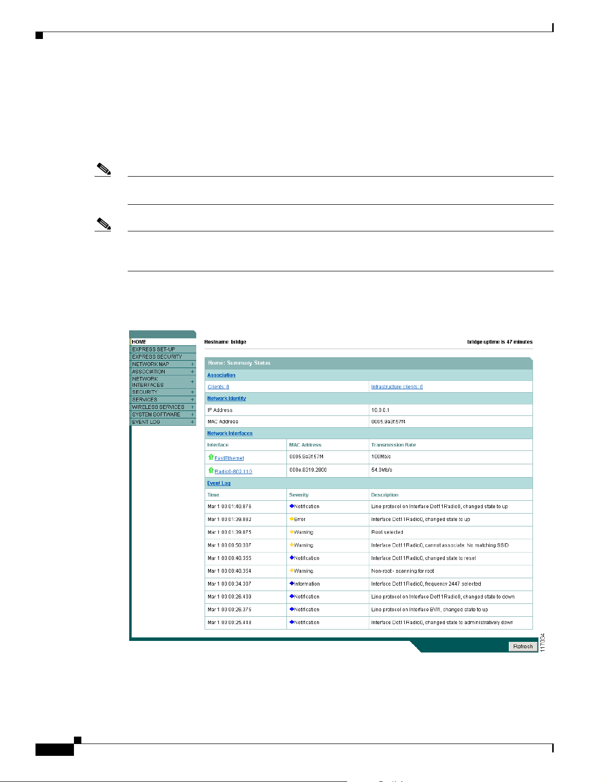
Chapter 4 Using the Web-Browser Interface
Using the Web-Browser Interface Management Pages
Using the Web-Browser Interface Management Pages
The access point/bridge management pages use consistent techniques to present and save configuration
information. A navigation bar is on the left side of the page, and configuration action buttons appear at
the bottom. You use the navigation bar to browse to other management pages, and you use the
configuration action buttons to save or cancel changes to the configuration.
Note The access point/bridge web-browser interface uses Windows Internet Explorer (version 6.0 or higher)
or Netscape Communicator (version 7.0 or higher) on your Windows-based PC.
Note Changes are applied only when you click Apply. It’s important to remember that clicking your browser’s
Back button returns you to the previous page without saving any changes you have made. Clicking
Cancel cancels any changes you made on the page and keeps you on that page.
Figure 4-1 shows the web-browser interface home page.
Figure 4-1 Web-Browser Interface Home Page
4-2
Cisco Aironet 1300 Series Outdoor Access Point/Bridge Hardware Installation Guide
OL-5048-02
Page 51

Chapter 4 Using the Web-Browser Interface
Using Action Buttons
Table 4-1 lists the page links and buttons that appear on most management pages.
Table 4-1 Common Buttons on Management Pages
Button or Link Description
Navigation Links
Home Displays access point/bridge status page with information on the number of
Express Setup Displays the Express Setup page that includes basic settings such as system
Express Security Displays the Express Security page that includes basic security settings such
Network Map Displays a list of infrastructure devices on your wireless LAN.
Association Displays a list of all devices on your wireless LAN, listing their system names,
Network Interfaces Displays status and statistics for the Ethernet and radio interfaces and provides
Security Displays a summary of security settings and provides links to security
Services Displays status for several access point/bridge features and links to other
System Software Displays the version number of the firmware that the access point/bridge is
Event Log Displays the access point/bridge event log and provides links to configuration
Configuration Action Buttons
Apply Saves changes made on the page and remains on the page.
Refresh Updates status information or statistics displayed on a page.
Cancel Discards changes to the page and remains on the page.
Back Discards any changes made to the page and returns to the previous page.
Using the Web-Browser Interface Management Pages
radio devices associated to the access point/bridge, the status of the Ethernet
and radio interfaces, and a list of recent access point/bridge activity.
name, IP address, and SSID.
as static WEP, EAP authentication, or WPA.
network roles, and parent-client relationships.
links to configuration pages for each interface.
configuration pages.
configuration pages.
running and provides links to configuration pages for upgrading and managing
firmware.
pages where you can select events to be included in traps, set event severity
levels, and set notification methods.
OL-5048-02
Cisco Aironet 1300 Series Outdoor Access Point/Bridge Hardware Installation Guide
4-3
Page 52

Using the Web-Browser Interface Management Pages
Character Restrictions in Entry Fields
Because the access point/bridge uses Cisco IOS software, there are certain characters that you cannot
use in the entry fields on the web-browser interface. Table 4-2 lists the prohibited characters and the
fields in which you cannot use them.
Table 4-2 Prohibited Characters for Web-Browser Interface Entry Fields
Entry Field Type Characters
Password entry fields ?
“
$
[
+
All other entry fields ?
“
$
[
+
You also cannot use these three characters as the first character in an entry
field:
!
#
;
Chapter 4 Using the Web-Browser Interface
Using Online Help
Click the help icon at the top of any page in the web-browser interface to display online help. Figure 4-2
shows the print and help icons.
Figure 4-2 Print and Help Icons
When a help page appears in a new browser window, use the Select a topic drop-down menu to display
the help index or instructions for common configuration tasks.
4-4
Cisco Aironet 1300 Series Outdoor Access Point/Bridge Hardware Installation Guide
OL-5048-02
Page 53

Chapter 4 Using the Web-Browser Interface
Connecting Locally to the Ethernet Port
If you need to configure the access point/bridge locally (without connecting to a wired LAN), you can
connect a PC to the power injector’s Ethernet port using a Category 5 Ethernet cable.
Note You do not need a special crossover cable to connect your PC to the power injector’s Ethernet port; you
can use either a straight-through cable or a crossover cable.
Your PC and the access point/bridge must be configured with compatible IP addresses and subnet masks
to be able to communicate on the Ethernet interface:
• If the access point/bridge is running Cisco IOS Release 12.2(15)JA or earlier and is configured with
default values, you must manually assign your PC an IP address from 10.0.0.31 to 10.0.0.40.
• If the access point/bridge is running Cisco IOS Release 12.3(2)JA2 or later and is configured with
default values, you must manually assign a temporary static IP address to the access point/bridge
and manally configure your PC with a compatible IP address and subnet mask.
For additonal information on configuring the access point/bridge, refer to the “Configuring the Access
Point/Bridge for the First Time” section on page 5-1.
Connecting Locally to the Ethernet Port
OL-5048-02
Cisco Aironet 1300 Series Outdoor Access Point/Bridge Hardware Installation Guide
4-5
Page 54

Connecting Locally to the Ethernet Port
Chapter 4 Using the Web-Browser Interface
4-6
Cisco Aironet 1300 Series Outdoor Access Point/Bridge Hardware Installation Guide
OL-5048-02
Page 55

CHA P TER
5
Configuring the Access Point/Bridge for the First Time
This chapter describes how to configure basic settings on your access point/bridge for the first time using
the web-browser interface. You can configure all the settings described in this chapter using the
command-line interface (CLI), but it might be simplest to browse to the access point/bridge’s
web-browser interface to complete the initial configuration and then use the CLI to enter additional
settings for a more detailed configuration.
This chapter contains these sections:
• Before You Start, page 5-2
• Resetting the Access Point/Bridge to Default Settings, page 5-2
• Default IP Address Behavior, page 5-2
• Default SSID and Default Role, page 5-3
• Obtaining and Assigning an IP Address, page 5-3
• Connecting to the Access Point/Bridge Locally, page 5-4
OL-5048-02
• Assigning Basic Settings, page 5-5
• Adjusting Output Power Level, page 5-9
• Configuring Basic Security Settings, page 5-9
• Finding the IP Address Using the CLI, page 5-13
• Assigning an IP Address Using the CLI, page 5-14
• Using a Telnet Session to Access the CLI, page 5-14
Cisco Aironet 1300 Series Outdoor Access Point/Bridge Hardware Installation Guide
5-1
Page 56

Chapter 5 Configuring the Access Point/Bridge for the First Time
Before You Start
Before You Start
Before you install the access point/bridge, make sure you are using a computer connected to the same
network as the access point/bridge, and obtain the following information from your network
administrator:
• A system name or host name for the access point/bridge
• The case-sensitive wireless service set identifier (SSID) for your radio network
• If not connected to a DHCP server, a unique IP address for your access point/bridge
• A default gateway address and subnet mask
• A Simple Network Management Protocol (SNMP) community name and the SNMP file attribute
Resetting the Access Point/Bridge to Default Settings
If you need to start over during the initial setup process, follow these steps to reset the
access point/bridge to factory default settings using the web-browser interface:
Step 1 Open your web-browser, such as Microsoft Internet Explorer (version 6.0 or higher) or Netscape
Communicator (version 7.0 or higher).
Step 2 Enter the access point/bridge IP address in the browser address line and press Enter. An Enter Network
Password window displays.
Step 3 Enter your username in the User Name field. The default username is Cisco.
Step 4 Enter the access point/bridge password in the Password field and press Enter. The default password is
Cisco. The Summary Status page displays.
Step 5 Click System Software and the System Software page displays.
Step 6 Click System Configuration and the System Configuration page displays.
Step 7 Click Reset to Defaults.
Note Optionally, you can click
Step 8 When the access point/bridge reboots, you can reconfigure the unit by using the Web-browser interface
or the CLI (refer to the Cisco IOS Software Configuration Guide for Cisco Aironet Bridges or to the
Cisco IOS Software Configuration Guide for Cisco Aironet Access Points).
Default IP Address Behavior
5-2
When you connect an access point/bridge running Cisco IOS Release 12.3(2)JA2 or later software with
a default configuration to your LAN, the access point/bridge requests an IP address from your DHCP
server and, if it does not receive an IP address, continues to send requests indefinitely.
Cisco Aironet 1300 Series Outdoor Access Point/Bridge Hardware Installation Guide
OL-5048-02
Page 57

Chapter 5 Configuring the Access Point/Bridge for the First Time
When you connect an access point/bridge running Cisco IOS Release 12.2(15)JA or earlier software with
a default configuration to your LAN, the access point/bridge requests an IP address from your DHCP
server and, if it does not receive an IP address, the access point/bridge assigns a default IP address of
10.0.0.1.
Default SSID and Default Role
In Cisco IOS Release 12.3(2)JA2 and earlier, on initial power up the access point/bridge defaults to the
Install-Mode role and supports these SSIDs:
• SSID is autoinstall for the Install-Mode role.
• SSID is tsunami for Root AP and Workgroup Bridge roles.
In Cisco IOS Release 12.3(4)JA, on initial power up the access point/bridge defaults to the Root AP
mode and no default SSID configured.
Obtaining and Assigning an IP Address
Default SSID and Default Role
To browse to the access point/bridge’s Express Setup page, you must either obtain or assign the access
point/bridge’s IP address using one of the following methods:
• Connect to the access point/bridge console port and assign a static IP address (refer to the “Using
the Power Injector’s Console Port” section on page 5-4 and the “Assigning an IP Address Using the
CLI” section on page 5-14).
• Use a DHCP server (if available) to automatically assign an IP address. You can find out the
DHCP-assigned IP address using one of the following methods:
–
Connect to the access point/bridge console port and use the show ip interface brief command
to display the IP address (refer to the “Using the Power Injector’s Console Port” section on
page 5-4).
–
Provide your organization’s network administrator with your access point/bridge’s Media
Access Control (MAC) address. Your network administrator will query the DHCP server using
the MAC address to identify the IP address.
OL-5048-02
Cisco Aironet 1300 Series Outdoor Access Point/Bridge Hardware Installation Guide
5-3
Page 58

Chapter 5 Configuring the Access Point/Bridge for the First Time
Connecting to the Access Point/Bridge Locally
Connecting to the Access Point/Bridge Locally
Using the Power Injector’s Ethernet Port
You can use the power injector’s Ethernet port to configure the access point/bridge locally (without
connecting to a wired LAN) using the web-browser or CLI interfaces. Follow these steps to connect to
the power injector’s Ethernet port:
Step 1 Connect a Category 5 Ethernet cable to your PC’s Ethernet connector and to the power injector’s
Ethernet port.
Note You do not need a special crossover cable to connect your PC to the power injector’s Ethernet
port; you can use either a straight-through cable or a crossover cable.
Step 2 Your PC and the access point/bridge must be configured with compatible IP addresses and subnet masks
to be able to communicate on the Ethernet interface. Perform one of these operations:
a. If the access point/bridge is running Cisco IOS Release 12.2(15)JA or earlier and is configured with
default values, you must manually assign your PC an IP address from 10.0.0.31 to 10.0.0.40.
b. If the access point/bridge is running Cisco IOS Release 12.3(2)JA2 or later and is configured with
default values, you must manually assign a temporary static IP address to the access point/bridge
and manally configure your PC with a compatible IP address and subnet mask. For additional
information, refer to the Obtaining and Assigning an IP Address, page 5-3.
Using the Power Injector’s Console Port
You can use the power injector’s console port for entering CLI commands. Follow these steps to connect
to the power injector’s console port:
Step 1 Connect a nine-pin, female DB-9 to RJ-45 serial cable to the RJ-45 serial console port on the power
injector and to the COM port on a computer.
Note The Cisco part number for the DB-9 to RJ-45 serial cable is AIR-CONCAB1200. Browse to
http://www.cisco.com/go/marketplace to order a serial cable.
Step 2 Set up a terminal emulator to communicate with the access point. Use the following settings for the
terminal emulator connection: 9600 baud, 8 data bits, no parity, 1 stop bit, and no flow control.
5-4
Note When your configuration changes are completed, you must remove the serial cable from the console
port.
Cisco Aironet 1300 Series Outdoor Access Point/Bridge Hardware Installation Guide
OL-5048-02
Page 59
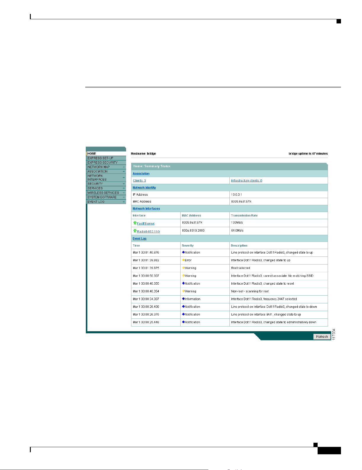
Chapter 5 Configuring the Access Point/Bridge for the First Time
Assigning Basic Settings
After you obtain the access point/bridge IP address, you can browse to its Express Setup page and
perform an initial configuration. Follow these steps:
Step 1 Browse to the access point/bridge IP address. An Enter Network Password window displays.
Step 2 Enter the case-sensitive username Cisco in the Username field.
Step 3 Enter the case-sensitive password Cisco in the Password field and press Enter. The Summary Status
page displays, which is the access point/bridge home page (see Figure 5-1).
Figure 5-1 Summary Status Page
Assigning Basic Settings
OL-5048-02
Cisco Aironet 1300 Series Outdoor Access Point/Bridge Hardware Installation Guide
5-5
Page 60

Assigning Basic Settings
Step 4 Click Express Setup. The Express Setup page displays. Figure 5-2 shows the Express Setup page.
Chapter 5 Configuring the Access Point/Bridge for the First Time
Figure 5-2 Express Setup Page
Step 5 Enter the configuration settings you obtained from your system administrator. The configurable settings
include:
• System Name or Host Name—The system name or host name, while not an essential setting, helps
identify the access point/bridge on your network. The name appears in the titles of the management
system pages.
• Configuration Server Protocol—Click the button that matches the network’s method of IP address
assignment.
–
DHCP—IP addresses are automatically assigned by your network’s DHCP server.
Note When DHCP is enabled, the IP Address, Subnet Mask, and Default Gateway fields indicate
Negotiated by DHCP.
–
Static IP—The access point/bridge uses a static IP address that you enter in the IP address field.
• IP Address—Use this setting to assign or change the access point/bridge’s IP address. If DHCP is
enabled for your network, leave this field blank.
Note If the access point/bridge’s IP address changes while you are configuring the access point/bridge
using the web-browser interface or a Telnet session over the wired LAN, you lose your
connection to the access point/bridge. If you lose your connection, reconnect to the access
point/bridge using its new IP address.
5-6
Cisco Aironet 1300 Series Outdoor Access Point/Bridge Hardware Installation Guide
OL-5048-02
Page 61

Chapter 5 Configuring the Access Point/Bridge for the First Time
• IP Subnet Mask—Enter the IP subnet mask provided by your network administrator so that the IP
address can be recognized on the LAN. If DHCP is enabled, leave this field blank.
• Default Gateway—Enter the default gateway IP address provided by your network administrator.
If DHCP is enabled, leave this field blank.
• SNMP Community—If your network is using SNMP, enter the SNMP Community name provided
by your network administrator and select the attributes of the SNMP data (also provided by your
network administrator).
–
Read-Only—indicates that the access point/bridge allows only SNMP read access. Using this
option, an SNMP user cannot change access point/bridge configuration settings.
–
Read-Write—indicates that the access point/bridge allows SNMP read and write access. This
setting allows an SNMP user to change the access point/bridge configuration.
• Role in Radio Network—Click on the check box that describes the role of the access point/bridge
on your network.
–
Install Mode—Activates the bridge install and alignment mode. Specifies that the unit
automatically determines the network role. If the init is able to associate to another Cisco
Aironet root bridge within 60 seconds, the unit assumes a non-root bridge role. If unable to
associate with another Cisco Aironet root bridge within 60 seconds, the unit assumes a root
bridge role.
You can also pre-configure the unit into root bridge or non-root bridge modes and avoid the
60-second automatic detection phase.
Assigning Basic Settings
–
Root—Specifies that the unit is operating as a root bridge and connects directly to the main
Ethernet LAN network. In this mode, the unit accepts associations from other Cisco Aironet
non-root bridges and wireless client devices.
–
Non-root—Specifies that the unit is operating as a non-root bridge and connects to a remote
LAN network and must associate with a Cisco Aironet root bridge using the wireless interface.
–
Root Access Point—Specifies that the unit operates as an access point connected to the main
Ethernet LAN network. In this mode, wireless client devices are allowed to associate to the
access point.
–
Workgroup Bridge—Specifies that the unit operates as a workgroup bridge connected to a
small wired Ethernet LAN network through an Ethernet hub or switch. The workgroup bridge
must associate to a Cisco Aironet access point or a Cisco Aironet bridge.
Note In Cisco IOS Release 12.3(2)JA2 or earlier, the access point/bridge is default configured in
bridge install mode with automatic bridge detection activated. In Cisco IOS Release 12.3(4)JA,
the access point/bridge is default configured in root access point mode.
• Optimize Radio Network for—Use this setting to select either preconfigured or customized
settings for the access point/bridge radio.
–
Throughput—Maximizes the data volume handled by the access point/bridge but might reduce
its range.
–
Range—Maximizes the access point/bridge’s range but might reduce throughput.
OL-5048-02
–
Default—The access point/bridge retains default radio settings that are designed to provide
good range and throughput.
–
Custom—The access point/bridge uses settings you enter on the Network Interfaces
Radio-802.11g Settings page. Clicking Custom takes you to the radio settings page.
Cisco Aironet 1300 Series Outdoor Access Point/Bridge Hardware Installation Guide
5-7
Page 62

Assigning Basic Settings
• Aironet Extensions—Enable this setting if there are only Cisco Aironet devices on your wireless
LAN and the unit is operating as an access point or workgroup bridge.
Step 6 Click Apply to save your settings. If you changed the IP address, you lose your connection to the access
point/bridge. Browse to the new IP address to reconnect to the access point/bridge.
Default Settings on the Express Setup Page
Table 5-1 lists the default settings for the settings on the Express Setup page.
Table 5-1 Default Settings on the Express Setup Page
Default Setting
Parameter
System Name or
Host Name
Configuration Server
Protocol
IP Address Assigned by DHCP
IP Subnet Mask Assigned by DHCP (default setting);
Default Gateway Assigned by DHCP (default setting);
SNMP defaultCommunity defaultCommunity
Role in Radio Network Install mode
Optimize Radio Network
for
1. After a static IP address is assigned or the role is changed from Install, the SSID is automatically changed to tsunami.
2. If an access point/bridge running Cisco IOS Release 12.3(2)JA2 or later software with a default configuration does not receive
an IP address from your DHCP server, it continues to send DHCP requests indefinitely.
3. During install mode, the SSID is autoinstall.
Cisco IOS Release 12.2(15)JA
bridge ap
DHCP DHCP
setting); if DHCP is disabled, the
default setting is 10.0.0.1
if DHCP is disabled, the default
setting is 255.255.255.224
if DHCP is disabled, the default
setting is 0.0.0.0
Read Only Read Only
3
Throughput Throughput
Chapter 5 Configuring the Access Point/Bridge for the First Time
Cisco IOS Release 12.3(2)JA2 or
later
1
(default
Assigned by DHCP by default
Assigned by DHCP by default
Assigned by DHCP by default
Access point (root)
2
5-8
Cisco Aironet 1300 Series Outdoor Access Point/Bridge Hardware Installation Guide
OL-5048-02
Page 63

Chapter 5 Configuring the Access Point/Bridge for the First Time
Enabling the Radio Interfaces
In Cisco IOS Release 12.3(4)JA, the access point/bridge radios are disabled by default, and there is no
default SSID. You must create an SSID and enable the radios before the access point/bridge will allow
wireless associations from other devices. These changes to the default configuration improve the
security of a newly installed access point/bridge. Refer to the “Configuring Basic Security Settings”
section on page 5-9 for instructions on configuring the SSID.
To enable the radio interfaces, follow these instructions:
Step 1 Use your web-browser to access your access point/bridge.
Step 2 When the Summary Status page displays, click Network Interfaces > Radio0-802.11g and the radio
status page displays.
Step 3 Click Settings and the radio settings page displays.
Step 4 Click Enable in the Enable Radio field.
Step 5 Click Apply.
Step 6 Close your web-browser.
Adjusting Output Power Level
Adjusting Output Power Level
Your access point/bridge’s output power level might require adjustment under the following conditions:
• The access point/bridge’s output power level must be reduced when using the 15-dBi sector or the
21-dBi dish antenna (refer to “Maximum Power Levels and Antenna Gains” section on page D-3).
• Your regulatory domain may limit the equivalent isotropic radiated power (EIRP) from the access
point/bridge’s antenna (refer to “Maximum Power Levels and Antenna Gains” section on page D-3).
To configure your access point/bridge’s output power level, refer to the “Changing the Access
Point/Bridge Output Power” section on page D-4.
Configuring Basic Security Settings
After you assign basic settings to your access point/bridge, you must configure security settings to
prevent unauthorized access to your network. Because it is a radio device, the access point/bridge can
communicate beyond the physical boundaries of your building.
Just as you use the Express Setup page to assign basic settings, you can use the Express Security page
(Cisco IOS Release 12.2(15)JA and later) to create unique SSIDs and assign one of four security types
to them. For detail security information, refer to the Cisco IOS Software Configuration Guide for Cisco
Aironet Access Points.
OL-5048-02
Cisco Aironet 1300 Series Outdoor Access Point/Bridge Hardware Installation Guide
5-9
Page 64
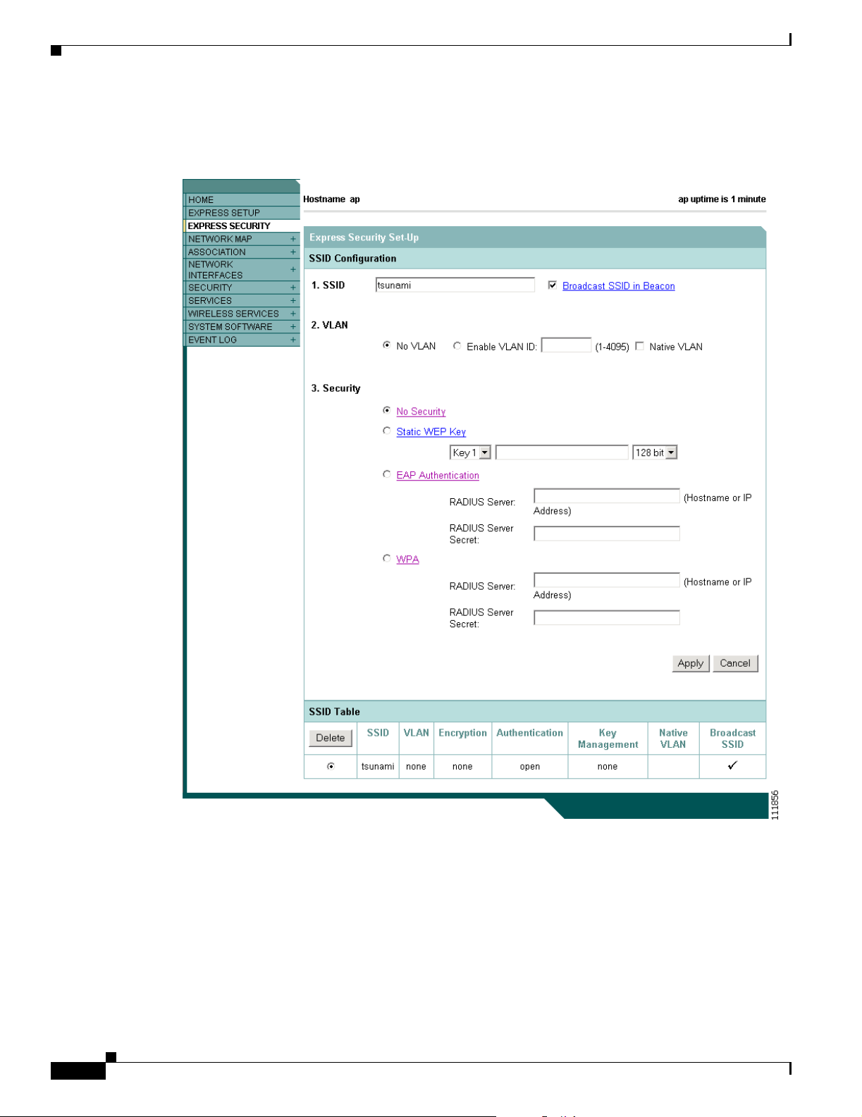
Configuring Basic Security Settings
Figure 5-3 shows the Express Security page.
Figure 5-3 Express Security Page
Chapter 5 Configuring the Access Point/Bridge for the First Time
5-10
Cisco Aironet 1300 Series Outdoor Access Point/Bridge Hardware Installation Guide
OL-5048-02
Page 65

Chapter 5 Configuring the Access Point/Bridge for the First Time
Understanding Express Security Settings
When the access point/bridge configuration is at factory defaults, the first SSID that you create by using
the Express Security page overwrites the default SSID (tsunami), which has no security settings. The
SSIDs that you create appear in the SSID table at the bottom of the page. You can create up to 16 SSIDs
on the access point/bridge.
Note In Cisco IOS Release 12.3(4)JA, there is no default SSID and the radio is disabled by default. You must
configure an SSID and enable the radio before client devices can associate to the access point.
Using VLANs
If you use VLANs on your wireless LAN and assign SSIDs to VLANs, you can create multiple SSIDs
by using any of the four security settings on the Express Security page. However, if you do not use
VLANs on your wireless LAN, the security options that you can assign to SSIDs are limited because on
the Express Security page encryption settings and authentication types are linked. Without VLANs,
encryption settings (WEP and ciphers) apply to an interface, such as the radio, and you cannot use more
than one encryption setting on an interface. For example, when you create an SSID with static WEP with
VLANs disabled, you cannot create additional SSIDs with WPA authentication because they use
different encryption settings. If you find that the security setting for an SSID conflicts with another
SSID, you can delete one or more SSIDs to eliminate the conflict.
If any VLANs are defined on the access point/bridge, the trunk port on the switch must be limited to
allow only the VLANs defined on the access point/bridge.
Configuring Basic Security Settings
Express Security Types
Table 5-2 describes the four security types that you can assign to an SSID.
Table 5-2 Security Types on Express Security Setup Page
Security Type Description Security Features Enabled
No Security This is the least secure option. You should
Static WEP Key This option is more secure than no security.
use this option only for SSIDs used in a
public space and assign it to a VLAN that
restricts access to your network.
However, static WEP keys are vulnerable to
attack. If you configure this setting, you
should consider limiting association to the
bridge based on MAC address (refer to the
Cisco IOS Software Configuration Guide
for Cisco Aironet Access Points).
None.
Mandatory WEP. Client devices
cannot associate using this SSID
without a WEP key that matches
the bridge’s key.
OL-5048-02
Cisco Aironet 1300 Series Outdoor Access Point/Bridge Hardware Installation Guide
5-11
Page 66

Configuring Basic Security Settings
Table 5-2 Security Types on Express Security Setup Page (continued)
Security Type Description Security Features Enabled
EAP
Authentication
WPA Wi-Fi Protected Access (WPA) permits
Chapter 5 Configuring the Access Point/Bridge for the First Time
This option enables 802.1x authentication
(such as LEAP, PEAP, EAP-TLS,
EAP-GTC, EAP-SIM, and others) and
requires you to enter the IP address and
shared secret for an authentication server on
your network (server authentication port
1645). Because 802.1x authentication
provides dynamic encryption keys, you do
not need to enter a WEP key.
wireless access to users authenticated
against a database through the services of
an authentication server, then encrypts their
IP traffic with stronger algorithms than
those used in WEP. As with EAP
authentication, you must enter the IP
address and shared secret for an
authentication server on your network
(server authentication port 1645).
Mandatory 802.1x authentication.
Client devices that associate using
this SSID must perform 802.1x
authentication.
Mandatory WPA authentication.
Client devices that associate using
this SSID must be WPA-capable.
28
Express Security Limitations
Because the Express Security page is designed for simple configuration of basic security, the options
available are a subset of the access point/bridge’s security capabilities. Keep these limitations in mind
when using the Express Security page:
• If the No VLAN option is selected, the static WEP key can be configured once. If you select Enable
VLAN, the static WEP key should be disabled.
• You cannot edit SSIDs. However, you can delete SSIDs and re-create them.
• You cannot assign SSIDs to specific radio interfaces. The SSIDs that you create are enabled on all
radio interfaces. To assign SSIDs to specific radio interfaces, use the Security SSID Manager page.
• You cannot configure multiple authentication servers. To configure multiple authentication servers,
use the Security Server Manager page.
• You cannot configure multiple WEP keys. To configure multiple WEP keys, use the Security
Encryption Manager page.
• You cannot assign an SSID to a VLAN that is already configured on the bridge. To assign an SSID
to an existing VLAN, use the Security SSID Manager page.
• You cannot configure combinations of authentication types on the same SSID (for example, MAC
address authentication and EAP authentication). To configure combinations of authentication types,
use the Security SSID Manager page.
5-12
Note For detailed information about security and security settings, refer to the Cisco IOS Software
Configuration Guide for Cisco Aironet Access Points.
Cisco Aironet 1300 Series Outdoor Access Point/Bridge Hardware Installation Guide
OL-5048-02
Page 67

Chapter 5 Configuring the Access Point/Bridge for the First Time
Using the Express Security Page
Follow these steps to create an SSID using the Express Security page:
Step 1 Type the SSID in the SSID entry field. The SSID can contain up to 32 alphanumeric characters.
Step 2 To broadcast the SSID in the access point/bridge beacon, check the Broadcast SSID in Beacon check
box. When you broadcast the SSID, devices that do not specify an SSID can associate to the bridge. This
is a useful option for an SSID used by guests or by client devices in a public space. If you do not
broadcast the SSID, client devices cannot associate to the access point/bridge unless their SSID matches
this SSID. Only one SSID can be included in the bridge beacon.
Step 3 (Optional) Check the Enable VLAN ID check box and enter a VLAN number (1 through 4095) to assign
the SSID to a VLAN. You cannot assign an SSID to an existing VLAN.
Step 4 (Optional) Check the Native VLAN check box to mark the VLAN as the native VLAN.
Step 5 Select the security setting for the SSID. The settings are listed in order of robustness, from No Security
to WPA, which is the most secure setting.
• If you select Static WEP Key, choose the key number and encryption key size and enter the
encryption key (10 hexidecimal characters for 40-bit keys or 26 hexidecimal characters for 128-bit
keys).
• If you select EAP Authentication or WPA, enter the IP address and shared secret for the
authentication server on your network.
Finding the IP Address Using the CLI
Note If you do not use VLANs on your wireless LAN, the security options that you can assign to
multiple SSIDs are limited. Refer to the Cisco IOS Software Configuration Guide for Cisco
Aironet Access Points for VLAN details.
Step 6 Click Apply. The SSID appears in the SSID table at the bottom of the page.
Finding the IP Address Using the CLI
When you connect the access point/bridge to the wired LAN, the access point/bridge links to the network
using a bridge virtual interface (BVI) that it creates automatically. Instead of tracking separate IP
addresses for the access point/bridge’s Ethernet and radio ports, the network uses the BVI.
To find the IP address of your access point/bridge using the console port, you can use the Cisco IOS CLI
show ip interface brief bvi1 from the privileged EXEC mode. For additional information on the CLI,
refer to the“Using the Command-Line Interface” section on page 5-1.
OL-5048-02
Cisco Aironet 1300 Series Outdoor Access Point/Bridge Hardware Installation Guide
5-13
Page 68

Chapter 5 Configuring the Access Point/Bridge for the First Time
Assigning an IP Address Using the CLI
Assigning an IP Address Using the CLI
When you connect the access point/bridge to the wired LAN, the access point links to the network using
a bridge virtual interface (BVI) that it creates automatically. Instead of tracking separate IP addresses
for the access point/bridge’s Ethernet and radio ports, the network uses the BVI.
When you assign an IP address to the access point/bridge using the CLI, you must assign the address to
the BVI. Beginning in privileged EXEC mode, follow these steps to assign an IP address to the access
point’s BVI:
Command Purpose
Step 1
Step 2
Step 3
configure terminal Enter global configuration mode.
interface bvi1 Enter interface configuration mode for the BVI.
ip address address
mask
Assign an IP address and address mask to the BVI.
Note If you are connected to the access point/bridge using a
Telnet session, you lose your connection when you
assign a new IP address to the BVI. If you need to
continue configuring the access point/bridge using
Telnet, use the new IP address to open another Telnet
session to the access point/bridge.
Using a Telnet Session to Access the CLI
Follow these steps to browse to access the CLI using a Telnet session. These steps are for a PC running
Microsoft Windows with a Telnet terminal application. Check your PC operating instructions for
detailed instructions for your operating system.
Step 1 Select Start > Programs > Accessories > Telnet.
If Telnet is not listed in your Accessories menu, select Start > Run, type Tel ne t in the entry field, and
press Enter.
Step 2 When the Telnet window displays, click Connect and select Remote System.
Note In Windows 2000, the Telnet window does not contain drop-down menus. To start the Telnet
session in Windows 2000, type open followed by the access point’s IP address.
Step 3 In the Host Name field, type the access point’s IP address and click Connect.
5-14
Cisco Aironet 1300 Series Outdoor Access Point/Bridge Hardware Installation Guide
OL-5048-02
Page 69

CHA P TER
6
Using the Command-Line Interface
This chapter describes the IOS command-line interface (CLI) that you can use to configure your access
point/bridge. It contains these sections:
• Connecting to the Console Serial Port, page 6-2
• Using a Telnet Session to Open the CLI, page 6-3
• IOS Command Modes, page 6-4
• Getting Help, page 6-5
• Abbreviating Commands, page 6-5
• Using no and default Forms of Commands, page 6-5
• Understanding CLI Messages, page 6-6
• Using Command History, page 6-6
• Using Editing Features, page 6-8
• Searching and Filtering Output of show and more Commands, page 6-10
• Assigning an IP Address Using the CLI, page 6-11
OL-5048-02
• Finding the Access Point/Bridge IP Address Using the CLI, page 6-11
Cisco Aironet 1300 Series Outdoor Access Point/Bridge Hardware Installation Guide
6-1
Page 70
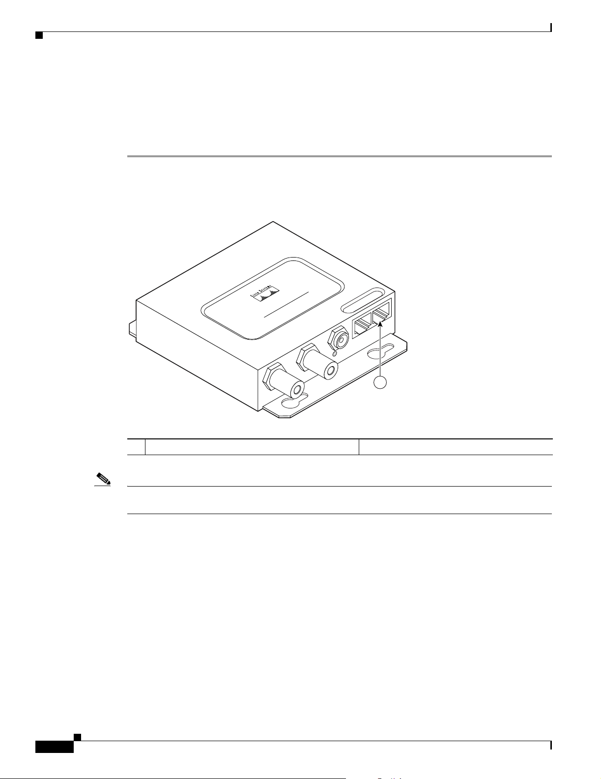
Connecting to the Console Serial Port
Connecting to the Console Serial Port
If you need to configure the access point/bridge locally (without connecting to a wired LAN), you can
connect a PC to the power injector console serial port using a DB-9 to RJ-45 serial cable. Follow these
steps to open the CLI by connecting to the console serial port:
Step 1 Connect a nine-pin, female DB-9 to RJ-45 serial cable to the RJ-45 serial port on the power injector and
to the COM port on your PC. Figure 6-1 shows the power injector’s console serial port connector.
Figure 6-1 Console Serial Port Connector
Chapter 6 Using the Command-Line Interface
POWER INJECTOR
CISCO AIRONET
117188
1
1 Console serial port connector (RJ-45 connector)
Note The Cisco part number for the DB-9 to RJ-45 serial cable is AIR-CONCAB1200. Browse to
http://www.cisco.com/go/marketplace to order a serial cable.
Step 2 Set up a terminal emulator to communicate with the access point/bridge. Use the following settings for
the terminal emulator connection: 9600 baud, 8 data bits, no parity, 1 stop bit, and no flow control.
Step 3 When the terminal emulator is activated, press Enter. An Enter Network Password window appears.
Step 4 Enter your username in the User Name field. The default username is Cisco.
Step 5 Enter the access point/bridge password in the Password field and press Enter. The default password is
Cisco.
When the CLI activates, you can enter CLI commands to configure the access point/bridge. For an
overview of the CLI interface, refer to the following sections. For detailed CLI information, refer to these
documents:
6-2
• Cisco IOS Software Configuration Guide for Cisco Aironet Bridges describes the access
point/bridge’s management system and explains how to configure the access point/bridge settings.
This document is available on the Cisco CCO web site at the following URL:
Cisco Aironet 1300 Series Outdoor Access Point/Bridge Hardware Installation Guide
OL-5048-02
Page 71

Chapter 6 Using the Command-Line Interface
http://www.cisco.com/univercd/cc/td/doc/product/wireless/index.htm
• Cisco IOS Command Reference for Cisco Aironet Access Points and Bridges describes the IOS
commands supported by Cisco Aironet access points and bridges. This document is available on the
Cisco CCO web site at the following URL:
http://www.cisco.com/univercd/cc/td/doc/product/wireless/index.htm
Using a Telnet Session to Open the CLI
Follow these steps to open the CLI using a Telnet session. These steps are for a PC running Microsoft
Windows with a Telnet terminal application. Check your PC operating instructions for detailed
instructions for your operating system.
Step 1 Select Start > Programs > Accessories > Telnet.
If Telnet is not listed in your Accessories menu, select Start > Run, type Te ln et in the entry field, and
press Enter.
Step 2 When the Telnet window appears, click Connect and select Remote System.
Using a Telnet Session to Open the CLI
Note In Windows 2000, the Telnet window does not contain drop-down menus. To start the Telnet
session in Windows 2000, type open followed by the access point/bridge’s IP address.
Step 3 In the Host Name field, type the access point/bridge’s IP address and click Connect.
Using Secure Shell to Open the CLI
Secure Shell Protocol is a protocol that provides a secure, remote connection to networking devices set
up to use it. Secure Shell (SSH) is a software package that provides secure login sessions by encrypting
the entire session. SSH features strong cryptographic authentication, strong encryption, and integrity
protection. For detailed information on SSH, visit the homepage of SSH Communications Security, Ltd.
at this URL:
http://www.ssh.com/
SSH provides more security for remote connections than Telnet by providing strong encryption when a
device is authenticated. Refer to the Cisco IOS Software Configuration Guide for Cisco Aironet Bridges
or to the Cisco IOS Software Configuration Guide for Cisco Aironet Access Points for detailed
instructions on setting up the access point/bridge for SSH access.
OL-5048-02
Cisco Aironet 1300 Series Outdoor Access Point/Bridge Hardware Installation Guide
6-3
Page 72

IOS Command Modes
IOS Command Modes
The Cisco IOS user interface is divided into many different modes. The commands available to you
depend on which mode you are currently in. Enter a question mark (?) at the system prompt to obtain a
list of commands available for each command mode.
When you start a session on the access point/bridge, you begin in user mode, often called user EXEC
mode. Only a limited subset of the commands are available in user EXEC mode. For example, most of
the user EXEC commands are one-time commands, such as show commands, which show the current
configuration status, and clear commands, which clear counters or interfaces. The user EXEC
commands are not saved when the access point/bridge reboots.
To have access to all commands, you must enter privileged EXEC mode. Normally, you must enter a
password to enter privileged EXEC mode. From this mode, you must enter privileged EXEC mode
before you can enter the global configuration mode.
Using the configuration modes (global, interface, and line), you can make changes to the running
configuration. If you save the configuration, these commands are stored and used when the access
point/bridge reboots. To access the various configuration modes, you must start at global configuration
mode. From global configuration mode, you can enter interface configuration mode and line
configuration mode.
Tabl e 6-1 describes the main command modes, how to access each one, the prompt you see in that mode, and
how to exit the mode. The examples in the table use the host name ap.
Chapter 6 Using the Command-Line Interface
Table 6-1 Command Mode Summary
Mode Access Method Prompt Exit Method About This Mode
User EXEC Begin a session with
your access
point/bridge.
br>
Enter logout or quit. Use this mode to
• Change terminal settings
• Perform basic tests
• Display system
information.
Privileged EXEC While in user EXEC
mode, enter the
enable command.
Global configuration While in privileged
EXEC mode, enter
the configure
br#
br(config)#
Enter disable to exit. Use this mode to verify
commands. Use a password to
protect access to this mode.
To exit to privileged
EXEC mode, enter exit or
end, or press Ctrl-Z.
Use this mode to configure
parameters that apply to the
entire access point/bridge.
command.
Interface
configuration
While in global
configuration mode,
enter the interface
command (with a
specific interface).
br(config-if)#
To exit to global
configuration mode, enter
exit. To return to
privileged EXEC mode,
press Ctrl-Z or enter end.
Use this mode to configure
parameters for the Ethernet
interfaces.
6-4
Cisco Aironet 1300 Series Outdoor Access Point/Bridge Hardware Installation Guide
OL-5048-02
Page 73

Chapter 6 Using the Command-Line Interface
Getting Help
You can enter a question mark (?) at the system prompt to display a list of commands available for each
command mode. You can also obtain a list of associated keywords and arguments for any command, as
shown in Table 6-2 .
Table 6-2 Help Summary
Command Purpose
help Obtains a brief description of the help system in any command mode.
abbreviated-command-entry? Obtains a list of commands that begin with a particular character string.
For example:
br# di?
dir disable disconnect
abbreviated-command-entry<Ta b> Completes a partial command name.
For example:
br# sh conf<tab>
br# show configuration
? Lists all commands available for a particular command mode.
For example:
br> ?
command ? Lists the associated keywords for a command.
Getting Help
For example:
br> show ?
command keyword ? Lists the associated arguments for a keyword.
For example:
br(config)# cdp holdtime ?
<10-255> Length of time (in sec) that receiver must keep this packet
Abbreviating Commands
You have to enter only enough characters for the access point/bridge to recognize the command as
unique. This example shows how to enter the show configuration privileged EXEC command:
br# show conf
Using no and default Forms of Commands
Most configuration commands also have a no form. In general, use the no form to disable a feature or
function or reverse the action of a command. For example, the no shutdown interface configuration
command reverses the shutdown of an interface. Use the command without the keyword no to re-enable
a disabled feature or to enable a feature that is disabled by default.
OL-5048-02
Cisco Aironet 1300 Series Outdoor Access Point/Bridge Hardware Installation Guide
6-5
Page 74

Understanding CLI Messages
Configuration commands can also have a default form. The default form of a command returns the
command setting to its default. Most commands are disabled by default, so the default form is the same
as the no form. However, some commands are enabled by default and have variables set to certain default
values. In these cases, the default command enables the command and sets variables to their default
values.
Understanding CLI Messages
Table 6-3 lists some error messages that you might encounter while using the CLI to configure your
access point/bridge.
Table 6-3 Common CLI Error Messages
Error Message Meaning How to Get Help
% Ambiguous command:
"show con"
% Incomplete command.
% Invalid input detected
at ‘^’ marker.
You did not enter enough characters
for your access point/bridge to
recognize the command.
You did not enter all the keywords or
values required by this command.
You entered the command
incorrectly. The caret (^) marks the
point of the error.
Re-enter the command followed by a question mark (?)
with a space between the command and the question
mark.
The possible keywords that you can enter with the
command are displayed.
Re-enter the command followed by a question mark (?)
with a space between the command and the question
mark.
The possible keywords that you can enter with the
command are displayed.
Enter a question mark (?) to display all the commands
that are available in this command mode.
The possible keywords that you can enter with the
command are displayed.
Chapter 6 Using the Command-Line Interface
Using Command History
Cisco IOS software provides a history or record of commands that you have entered. This feature is
particularly useful for recalling long or complex commands or entries, including access lists. You can
customize the command history feature to suit your needs as described in these sections:
• Changing the Command History Buffer Size, page 6-7
• Recalling Commands, page 6-7
• Disabling the Command History Feature, page 6-7
Cisco Aironet 1300 Series Outdoor Access Point/Bridge Hardware Installation Guide
6-6
OL-5048-02
Page 75

Chapter 6 Using the Command-Line Interface
Changing the Command History Buffer Size
By default, the access point/bridge records ten command lines in its history buffer. Beginning in
privileged EXEC mode, enter this command to change the number of command lines that the access
point/bridge records during the current terminal session:
br# terminal history [size number-of-lines]
The range is from 0 to 256.
Beginning in line configuration mode, enter this command to configure the number of command lines
the access point/bridge records for all sessions on a particular line:
br(config-line)# history [size number-of-lines]
The range is from 0 to 256.
Recalling Commands
To recall commands from the history buffer, perform one of the actions listed in Ta ble 6-4:
Using Command History
Table 6-4 Recalling Commands
Action Result
Press Ctrl-P or the up arrow key.
Press Ctrl-N or the down arrow key.
show history While in privileged EXEC mode, lists the last several commands that you just
1. The arrow keys function only on ANSI-compatible terminals such as VT100s.
1
Recalls commands in the history buffer, beginning with the most recent command.
Repeat the key sequence to recall successively older commands.
1
Returns to more recent commands in the history buffer after recalling commands
with Ctrl-P or the up arrow key. Repeats the key sequence to recall successively
more recent commands.
entered. The number of commands that are displayed is determined by the setting
of the terminal history global configuration command and history line
configuration command.
Disabling the Command History Feature
The command history feature is automatically enabled.
To disable the feature during the current terminal session, enter the terminal no history privileged
EXEC command.
To disable command history for the line, enter the no history line configuration command.
OL-5048-02
Cisco Aironet 1300 Series Outdoor Access Point/Bridge Hardware Installation Guide
6-7
Page 76

Using Editing Features
Using Editing Features
This section describes the editing features that can help you manipulate the command line. It contains
these sections:
• Enabling and Disabling Editing Features, page 6-8
• Editing Commands Through Keystrokes, page 6-8
• Editing Command Lines That Wrap, page 6-9
Enabling and Disabling Editing Features
Although enhanced editing mode is automatically enabled, you can disable it.
To re-enable the enhanced editing mode for the current terminal session, enter this command in
privileged EXEC mode:
br# terminal editing
To reconfigure a specific line to have enhanced editing mode, enter this command in line configuration
mode:
br(config-line)# editing
Chapter 6 Using the Command-Line Interface
To globally disable enhanced editing mode, enter this command in line configuration mode:
br(config-line)# no editing
Editing Commands Through Keystrokes
Table 6-5 shows the keystrokes that you need to edit command lines.
Table 6-5 Editing Commands Through Keystrokes
Capability Keystroke Purpose
Move around the command line to
make changes or corrections.
Recall commands from the buffer and
paste them in the command line. The
access point/bridge provides a buffer
with the last ten items that you
deleted.
Ctrl-B or the left arrow
1
key
Ctrl-F or the right arrow
1
key
Ctrl-A Move the cursor to the beginning of the command line.
Ctrl-E Move the cursor to the end of the command line.
Esc B Move the cursor back one word.
Esc F Move the cursor forward one word.
Ctrl-T Transpose the character to the left of the cursor with the
Ctrl-Y Recall the most recent entry in the buffer.
Esc Y Recall the next buffer entry.
Move the cursor back one character.
Move the cursor forward one character.
character located at the cursor.
The buffer contains only the last 10 items that you have
deleted or cut. If you press Esc Y more than ten times, you
cycle to the first buffer entry.
6-8
Cisco Aironet 1300 Series Outdoor Access Point/Bridge Hardware Installation Guide
OL-5048-02
Page 77

Chapter 6 Using the Command-Line Interface
Table 6-5 Editing Commands Through Keystrokes (continued)
Capability Keystroke Purpose
Delete entries if you make a mistake
or change your mind.
Capitalize or lowercase words or
capitalize a set of letters.
Designate a particular keystroke as
an executable command, perhaps as a
shortcut.
Scroll down a line or screen on
displays that are longer than the
terminal screen can display.
Delete or Backspace Erase the character to the left of the cursor.
Ctrl-D Delete the character at the cursor.
Ctrl-K Delete all characters from the cursor to the end of the
command line.
Ctrl-U or Ctrl-X Delete all characters from the cursor to the beginning of
the command line.
Ctrl-W Delete the word to the left of the cursor.
Esc D Delete from the cursor to the end of the word.
Esc C Capitalize at the cursor.
Esc L Change the word at the cursor to lowercase.
Esc U Capitalize letters from the cursor to the end of the word.
Ctrl-V or Esc Q
Return Scroll down one line.
Space Scroll down one screen.
Using Editing Features
Note The More prompt appears for
output that has more lines
than can be displayed on the
terminal screen, including
show command output. You
can use the Return and
Space bar keystrokes
whenever you see the
More
prompt.
Redisplay the current command line
Ctrl-L or Ctrl-R Redisplay the current command line.
if the access point/bridge suddenly
sends a message to your screen.
1. The arrow keys function only on ANSI-compatible terminals such as VT100s.
Editing Command Lines That Wrap
You can use a wrap-around feature for commands that extend beyond a single line on the screen. When
the cursor reaches the right margin, the command line shifts ten spaces to the left. You cannot see the
first ten characters of the line, but you can scroll back and check the syntax at the beginning of the
command.
To scroll back to the beginning of the command entry, press Ctrl-B or the left arrow key repeatedly. You
can also press Ctrl-A to immediately move to the beginning of the line.
OL-5048-02
Note The arrow keys function only on ANSI-compatible terminals such as VT100s.
Cisco Aironet 1300 Series Outdoor Access Point/Bridge Hardware Installation Guide
6-9
Page 78

Searching and Filtering Output of show and more Commands
In this example, the access-list global configuration command entry extends beyond one line. When the
cursor reaches the end of the line, the line is shifted ten spaces to the left and redisplayed. The dollar
sign ($) shows that the line has been scrolled to the left. Each time the cursor reaches the end of the line,
the line is again shifted ten spaces to the left.
br(config)# access-list 101 permit tcp 131.108.2.5 255.255.255.0 131.108.1
br(config)# $ 101 permit tcp 131.108.2.5 255.255.255.0 131.108.1.20 255.25
br(config)# $t tcp 131.108.2.5 255.255.255.0 131.108.1.20 255.255.255.0 eq
br(config)# $108.2.5 255.255.255.0 131.108.1.20 255.255.255.0 eq 45
After you complete the entry, press Ctrl-A to check the complete syntax before pressing the Return key
to execute the command. The dollar sign ($) appears at the end of the line to show that the line has been
scrolled to the right:
br(config)# access-list 101 permit tcp 131.108.2.5 255.255.255.0 131.108.1$
If you have a terminal screen width other than 80 columns, use the terminal width privileged EXEC
command to set the width of your terminal.
Use line wrapping with the command history feature to recall and modify previous complex command
entries. For information about recalling previous command entries, see the “Editing Commands Through
Keystrokes” section on page 6-8.
Chapter 6 Using the Command-Line Interface
Searching and Filtering Output of show and more Commands
You can search and filter the output for show and more commands, which is useful when sorting through
large amounts of output or when excluding output.
To use this functionality, enter a show or more command followed by the pipe character (|), one of the
keywords begin, include, or exclude, and an expression that you want to search for or filter out:
command | {begin | include | exclude} regular-expression
Expressions are case sensitive. For example, if you enter | exclude output, the lines that contain output
are not displayed, but the lines that contain Output are displayed.
This example shows how to include in the output display only lines where the expression protocol
appears:
br# show interfaces | include protocol
Vlan1 is up, line protocol is up
Vlan10 is up, line protocol is down
GigabitEthernet0/1 is up, line protocol is down
GigabitEthernet0/2 is up, line protocol is up
6-10
Cisco Aironet 1300 Series Outdoor Access Point/Bridge Hardware Installation Guide
OL-5048-02
Page 79

Chapter 6 Using the Command-Line Interface
Assigning an IP Address Using the CLI
When you connect the access point/bridge to the wired LAN, the access point/bridge links to the network
using a access point/bridge virtual interface (BVI) that it creates automatically. Instead of tracking
separate IP addresses for the access point/bridge’s Ethernet and radio ports, the network uses the BVI.
When you assign an IP address to the access point/bridge using the CLI, you must assign the address to
the BVI. Beginning in privileged EXEC mode, follow these steps to assign an IP address to the access
point/bridge’s BVI:
Command Purpose
Step 1
Step 2
Step 3
configure terminal Enter global configuration mode.
interface bvi1 Enter interface configuration mode for the BVI.
ip address address
mask
Assign an IP address and address mask to the BVI. This step
automatically saves the running configuration to the startup
configuration.
Note You lose your connection to the access point/bridge when you
assign a new IP address to the BVI. If you need to continue
configuring the access point/bridge, use the new IP address to
open another Telnet session to the access point/bridge.
Assigning an IP Address Using the CLI
Finding the Access Point/Bridge IP Address Using the CLI
You can find the access point/bridge IP address using the following CLI command from the user EXEC
mode:
Command Purpose
Step 1
show interface bvi1 Display the IP address for the interface BVI.
OL-5048-02
Cisco Aironet 1300 Series Outdoor Access Point/Bridge Hardware Installation Guide
6-11
Page 80

Finding the Access Point/Bridge IP Address Using the CLI
Chapter 6 Using the Command-Line Interface
6-12
Cisco Aironet 1300 Series Outdoor Access Point/Bridge Hardware Installation Guide
OL-5048-02
Page 81

CHA P TER
7
Troubleshooting
This chapter provides troubleshooting procedures for basic problems with the access point/bridge. For
the most up-to-date, detailed troubleshooting information, refer to the CiscoTechnical Support and
Documentation website at the following URL:
http://www.cisco.com/en/US/products/hw/wireless/tsd_products_support_category_home.html
Sections in this chapter include:
• Checking the LEDs, page 7-2
• Power Injector, page 7-5
• Checking Power, page 7-6
• Checking Basic Configuration Settings, page 7-6
• Antenna Alignment, page 7-8
• Resetting the Access Point/Bridge to the Default Configuration, page 7-10
• Reloading the Access Point/Bridge Image, page 7-11
OL-5048-02
Cisco Aironet 1300 Series Outdoor Access Point/Bridge Hardware Installation Guide
7-1
Page 82

Checking the LEDs
Checking the LEDs
If your access point/bridge is not associating with a remote bridge or access point, check the four LEDs
on the back panel. You can use them to quickly assess the unit’s status. For information on using the
LEDs during the installation and alignment of the access point/bridge antenna, refer to the “LEDs”
section on page 3-5.
Figure 7-1 shows the access point/bridge LEDs.
Figure 7-1 LEDs
Chapter 7 Troubleshooting
RSIE
117061
R Radio LED E Ethernet LED
S Status LED I Install LED
Normal Mode LED Indications
During access point/bridge operation the LEDs provide status information as shown in Tab l e 7- 1.
Table 7-1 LED Indications
Ethernet
LED
Off — — — Ethernet link is down or disabled.
Blinking
green
Blinking
amber
amber — — — Firmware error—disconnect and reconnect the power injector power
Status
LED
— — — Transmitting and receiving Ethernet packets.
— — — Transmitting and receiving Ethernet errors.
Radio
LED
Install
LED
Meaning
jack. If the problem continues, contact technical support for
assistance.
7-2
Cisco Aironet 1300 Series Outdoor Access Point/Bridge Hardware Installation Guide
OL-5048-02
Page 83

Chapter 7 Troubleshooting
Table 7-1 LED Indications (continued)
Checking the LEDs
Ethernet
LED
— Blinking
Status
LED
green
Radio
LED
Install
LED
Meaning
— — Root bridge mode—no remote bridges are associated.
Non-root bridge mode—not associated to the root bridge.
If all bridges are powered up, this could be caused by incorrect SSID
and security settings or improper antenna alignment. You should check
the SSID and security settings of all bridges and verify antenna
alignment.
If the problem continues, contact technical support for assistance.
— Green — — Root mode—associated to at least one remote bridge.
Non-root mode—associated to the root bridge.
This is normal operation.
— Blinking
amber
— — General warning—disconnect and reconnect the power injector power
jack. If the problem continues, contact technical support for
assistance.
— Amber — — Loading firmware.
Red Amber Red — Loading Firmware error—disconnect and reconnect the power injector
power. If the problem continues, contact technical support for
assistance.
— — Off — Normal operation.
— — Blinking
— Transmitting and receiving radio packets—normal operation.
green
— — Blinking
amber
— Maximum retries or buffer full occurred on the radio
interface—disconnect and reconnect the power injector power jack. If
the problem continues, contact technical support for assistance.
— — Amber — Radio firmware error—disconnect and reconnect power injector
power. If the problem continues, contact technical support for
assistance.
———Amber
blinking
Not associated (non-root mode). The access point/bridge attempts to
associate with a root bridge for 60 seconds
1
.
— — — Amber Associated (non-root mode).
— — — Green
blinking
Not associated (root mode). The access point/bridge attempts to
associate with a non-root bridge indefinitely.
— — — Green Associated (root mode).
— — — Red Overcurrent or overvoltage error—disconnect power to the power
injector, check all coax cable connections, wait approximately 1
minute, and reconnect power. If error continues, contact technical
support.
1. Preconfigured bridges search indefinitely.
OL-5048-02
The access point/bridge uses a blinking code to identify various error conditions. The code sequence uses
a two-digit diagnostic code that starts with a long pause to delimit the code, followed by the LED
flashing red to count out the first digit, then a short pause, followed by the LED flashing red to count out
the second digit.
Cisco Aironet 1300 Series Outdoor Access Point/Bridge Hardware Installation Guide
7-3
Page 84

Checking the LEDs
Chapter 7 Troubleshooting
The LED blinking error codes are described in Tab le 7-2.
Table 7-2 LED Blinking Error Codes
Blinking Codes
First
LED
Digit
Ethernet 2 1 Ethernet cable problem—verify that the cable is properly connected
Radio 1 2 Radio not detected—contact technical support for assistance.
1 3 Radio not ready—contact technical support for assistance.
1 4 Radio did not start—contact technical support for assistance.
1 5 Radio failure—contact technical support for assistance.
1 6 Radio did not flash its firmware—contact technical support for
Second
Digit
Description
and not defective. This error might also indicate a problem with the
Ethernet link. If the cable is connected properly and not defective,
contact technical support for assistance.
assistance.
7-4
Cisco Aironet 1300 Series Outdoor Access Point/Bridge Hardware Installation Guide
OL-5048-02
Page 85
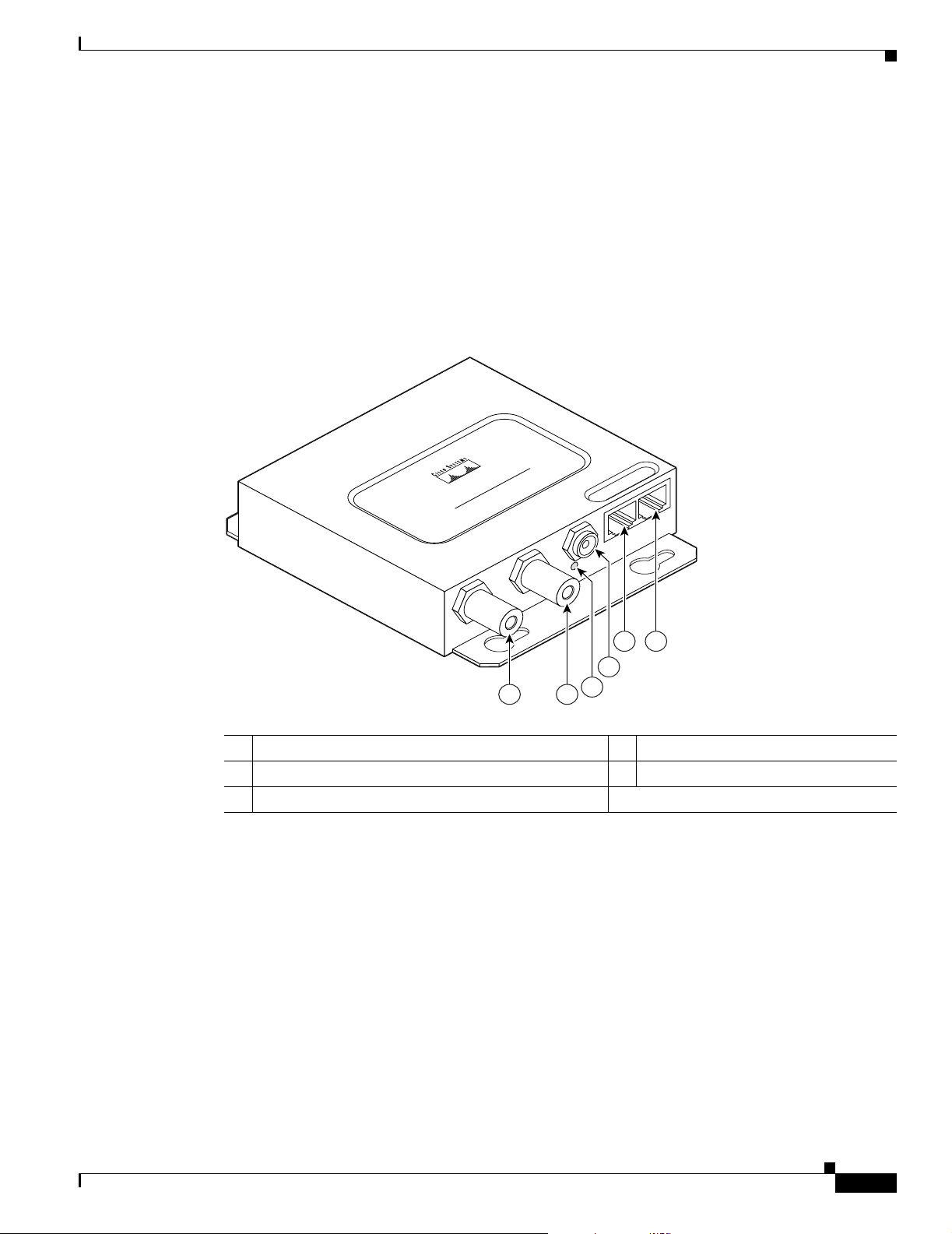
Chapter 7 Troubleshooting
Power Injector
When the power injector is powered up, it applies 48-VDC to the dual-coax cables to the access
point/bridge.
When power is applied to the access point/bridge, the unit activates the bootloader and begins the POST
operations. The access point/bridge begins to load the Cisco IOS image when the POST operations are
successfully completed. Upon successfully loading the image, the unit initializes and tests the radio.
The power injector LED is shown in Figure 7-2.
Figure 7-2 Power Injector
Power Injector
POWER INJECTOR
CISCO AIRONET
117189
54
3
2
11
1 Dual-coax Ethernet ports (F-Type connectors) 4 Ethernet LAN port (RJ-45 connector)
2 Power LED 5 Console serial port (RJ-45 connector)
3 Power jack
The power injector is available in two models:
• Cisco Aironet Power Injector LR2—standard version (included with the bridge)
–
48-VDC input power
–
Uses the 48-VDC power module (included with the bridge)
• Cisco Aironet Power Injector LR2T—optional transportation version
OL-5048-02
–
12- to 40-VDC input power
–
Uses 12 to 40 VDC from a vehicle battery
Cisco Aironet 1300 Series Outdoor Access Point/Bridge Hardware Installation Guide
7-5
Page 86

Checking Power
Checking Power
You can verify the availability of power to the access point/bridge by checking the power injector LED
(see Figure 7-2):
• Power LED
–
Green color indicates input power is being supplied to the bridge.
–
Red color indicates an overcurrent or overvoltage error condition—disconnect input power from
the power injector, check all coax cable connections for a possible short, wait approximately 1
minute, and reconnect input power to the power injector. If the LED turns red again, contact
technical support for assistance.
Note The power injector requires approximately 50 seconds to recover from an overcurrent or
–
Off indicates input power is not available—verify that the power module is connected to the
power injector and that AC power is available or that 12- to 40-VDC input power is connected
to the power injector.
Chapter 7 Troubleshooting
overvoltage condition.
Checking Basic Configuration Settings
Mismatched basic settings are the most common causes of lost wireless connectivity. Check the
following areas.
Default IP Address Behavior
When you connect an access point/bridge running Cisco IOS Release 12.3(2)JA or later software with a
default configuration to your LAN, the access point/bridge requests an IP address from your DHCP
server and, if it does not receive an IP address, continues to send requests indefinitely. To eliminate this
behavior, you must access the access point/bridge through its console port and assign a static IP address.
When you connect an access point/bridge running Cisco IOS Release 12.2(15)JA2 or earlier software
with a default configuration to your LAN, the access point/bridge requests an IP address from your
DHCP server and, if it does not receive an IP address, it assigns a default IP address of 10.0.0.1
Default SSID and Radio Behavior
In Cisco IOS Release 12.3(2)JA2 and earlier, on initial power up the access point/bridge defaults to the
Install-Mode role with the radio enabled and supports these SSIDs:
• SSID is autoinstall for the Install-Mode role.
• SSID is tsunami for Root AP and Workgroup Bridge roles.
In Cisco IOS Release 12.3(4)JA, on initial power up the access point/bridge defaults to the Root AP role
with the radio disabled and no default SSID configured.
7-6
Cisco Aironet 1300 Series Outdoor Access Point/Bridge Hardware Installation Guide
OL-5048-02
Page 87

Chapter 7 Troubleshooting
Note In Cisco IOS Release 12.3(4)JA, you must create an SSID and enable the radio before the access
point/bridge allows wireless associations from other devices. These changes to the default configuration
improve the security of a newly installed access point/bridge. Refer to the “Configuring Basic Security
Settings” section on page 3-9 for instructions on configuring the SSID and to the “Enabling the Radio
Interface” section on page 7-7 for instructions on enabling the radio interface.
Enabling the Radio Interface
To enable the radio interface, follow these instructions:
Step 1 Use your web-browser to access your access point/bridge.
Step 2 When the Summary Status page displays, click Network Interfaces > Radio0-802.11g and the radio
status page displays.
Step 3 Click Settings and the radio settings page displays.
Step 4 Click Enable in the Enable Radio field.
Step 5 Click Apply.
Step 6 Close your web-browser.
Checking Basic Configuration Settings
SSID
To associate, all bridges, access points, workgroup bridges, or client devices must use the same SSID.
The bridge installation mode SSID is autoinstall and the normal mode default SSID is tsunami. You
should verify that the SSID value shown on the Express Setup page is the same for all bridges, access
points, workgroup bridges, or client devices. You should also verify that the bridges or access points are
configured for the proper network role; only one bridge can be configured as the root bridge and only
one access point can be configured as a root access point.
Note Access points and bridges are not designed to associate with each other. However, a workgroup bridge
can associate to either a Cisco Aironet access point or a Cisco Aironet bridge.
Note In Cisco IOS Release 12.3(4)JA, there is no default SSID in the Root AP and Workgroup Bridge roles.
You must configure an SSID and enable the radio interface to communicate with other wireless devices.
OL-5048-02
Cisco Aironet 1300 Series Outdoor Access Point/Bridge Hardware Installation Guide
7-7
Page 88

Antenna Alignment
Security Settings
Remote Cisco Aironet bridges or client devices attempting to authenticate to your access point/bridge
must support the same security options configured in the access point/bridge, such as WEP, EAP or
LEAP, MAC address authentication, Message Integrity Check (MIC), WEP key hashing, and 802.1X
protocol versions.
If a Cisco Aironet non-root bridge or a non-root access point is unable to authenticate to your root bridge
or root access point, verify that the security settings are the same as your access point/bridge settings.
For additional information, refer to the Cisco IOS Software Configuration Guide for Cisco Aironet
Bridges or to the Cisco IOS Software Configuration Guide for Cisco Aironet Access Points.
Antenna Alignment
If your non-root bridges or non-root access points are unable to associate to your root bridge or root
access point, you should verify the basic configuration settings on all bridges or access points before
attempting to verify antenna alignment (refer to “Configuring the Access Point/Bridge for the First
Time” section on page 5-1). If your basic configuration settings are correct, you can verify antenna
alignment by using the Install mode RSSI LED indications. For additional information, refer to the
“Aligning the Bridge Antenna Using RSSI LED Indications” section on page 3-7.
For detailed alignment instructions, refer to the Cisco Aironet 1300 Series Outdoor Access Point/Bridge
Mounting Instructions that shipped with your access point/bridge.
Chapter 7 Troubleshooting
Note To meet regulatory restrictions, the external antenna access point/bridge unit and the external antenna
must be professionally installed. The network administration or other IT professional responsible for
installing and configuring the unit is a suitable professional installer. Following installation, access to the
unit should be password protected by the network administrator to maintain regulatory compliance.
Running the Carrier Busy Test
You can use the carrier busy test to determine the least congested channel for the radio interface
(802.11g). You should typically run the test several times to obtain the best results and to avoid
temporary activity spikes.
Note The carrier busy test is primarily used for single access points or bridge environments. For sites with
multiple access points, a site survey is typically performed to determine the best operating locations and
operating frequencies for the access points.
Note All associated clients on the selected radio will be disassociated during the 6 to 8 seconds needed for the
carrier busy test.
Follow these steps to activate the carrier busy test:
7-8
Step 1 Use your web browser to access the access point browser interface.
Step 2 Click Network Interfaces and the Network Interface Summary page appears.
Cisco Aironet 1300 Series Outdoor Access Point/Bridge Hardware Installation Guide
OL-5048-02
Page 89

Chapter 7 Troubleshooting
Step 3 Choose the radio interface by clicking Radio0-802.11G. The radio status page appears.
Step 4 Click the Carrier Busy Test tab and the Carrier Busy Test page appears.
Step 5 Click Start to begin the carrier busy test.
When the test completes, the results are displayed on the bottom of the page. For each of the channel
center frequencies, the test produces a value indicating the percentage of time that the channel is busy.
Running the Ping or Link Test
You can use the ping or link test to evaluate the communication link with an associated wireless device.
The ping or link test provides two modes of operation:
• Uses a specified number of packets and then displays the test results.
• Continuously operates until you stop the test and then displays the test results.
Follow these steps to activate the ping or link test:
Running the Ping or Link Test
Step 1 Use your web browser to access the access point browser interface.
Step 2 Click Association and the main association page appears.
Step 3 Click the MAC address of an associated wireless device and the Statistics page for that device appears.
Step 4 Click the Ping/Link Test tab and the Ping/Link Test page appears.
Step 5 If you want to specify the number of packets to use in the test, follow these steps:
a. Enter the desired number of packets in the Number of Packets field.
b. Enter the desired packet size in the Packet Size field.
c. Click Start. The test automatically stops when all packets are used.
Step 6 If you want to use a continuous test, follow these steps:
a. Enter the desired packet size in the Packet Size field.
b. Click Start to activate the test.
c. When desired, click Stop to stop the test.
When the test stops, the test results are displayed at the bottom of the page. You should check for lost
packets that might indicate a possible problem with the wireless link. For best results, you should
perform this test several times.
OL-5048-02
Cisco Aironet 1300 Series Outdoor Access Point/Bridge Hardware Installation Guide
7-9
Page 90

Chapter 7 Troubleshooting
Resetting the Access Point/Bridge to the Default Configuration
Resetting the Access Point/Bridge to the Default Configuration
You can use the web-browser interface or the CLI to reset the access point/bridge to a factory default
configuration.
Note The following steps reset all configuration settings to factory defaults, including passwords, WEP keys,
the IP address, and the SSID.
For additional information on access point/bridge default behavior, refer to the “Default IP Address
Behavior” section on page 7-6 and the “Default SSID and Radio Behavior” section on page 7-6.
Using the Web-Browser Interface
Follow the steps below to delete the current configuration and return all access point/bridge settings to
the factory defaults using the Web-browser interface.
Step 1 Open your web-browser.
Step 2 Enter the bridge’s IP address in the browser address or location line and press Enter. An Enter Network
Step 3 Enter your username (default Cisco) in the User Name field.
Step 4 Enter the access point/bridge password (default Cisco) in the Password field and press Enter. The
Step 5 Click System Software and the System Software page appears.
Step 6 Click System Configuration and the System Configuration page appears.
Step 7 Click Default.
Step 8 After the access point/bridge reboots, you can reconfigure the access point/bridge by using the
Using the CLI
Password window appears.
Summary Status page appears.
Note If the access point/bridge is configured with a static IP address, the IP address does not change.
Web-browser interface or the CLI (refer to the Cisco IOS Software Configuration Guide for Cisco
Aironet Bridges or to the Cisco IOS Software Configuration Guide for Cisco Aironet Access Points).
7-10
From the privileged EXEC mode, you can reset the access point/bridge configuration to factory default
values using the CLI by following these steps:
Step 1 Enter erase nvram: to erase all NVRAM files including the startup configuration.
Step 2 Enter Y when the following CLI message displays: Erasing the nvram filesystem will remove all
configuration files! Continue? [confirm].
Step 3 Enter reload when the following CLI message displays: Erase of nvram: complete. This command
reloads the operating system.
Cisco Aironet 1300 Series Outdoor Access Point/Bridge Hardware Installation Guide
OL-5048-02
Page 91

Chapter 7 Troubleshooting
Step 4 Enter Y when the following CLI message displays: Proceed with reload? [confirm].
Caution Interrupting the boot process will damage the configuration file. Wait until the access point/bridge Install
Mode LED begins to blink green before continuing with CLI configuration changes. You can also see
the following CLI message when the load process has finished: Line protocol on Interface Dot11Radio0,
changed state to up.
Step 5 After the access point/bridge reboots, you can reconfigure the access point/bridge by using the
Web-browser interface or the CLI (refer to the Cisco IOS Software Configuration Guide for Cisco
Aironet Bridges or to the Cisco IOS Software Configuration Guide for Cisco Aironet Access Points).
The access point/bridge is configured with the factory default values including the IP address (set to
receive an IP address using DHCP). To obtain the unit’s new IP address, you can use the show interface
bvi1 CLI command.
Reloading the Access Point/Bridge Image
Reloading the Access Point/Bridge Image
If your access point/bridge has a firmware failure, you must reload the complete image file using the
Web-browser interface or by using the console serial port. You can use the browser interface if the access
point/bridge firmware is operational. However, you can use the console serial port when the access
point/bridge has a corrupt image.
Web-Browser Interface
You can also use the Web-browser interface to reload the access point/bridge image file. The
Web-browser interface supports loading the image file using HTTP or TFTP interfaces.
Note Your access point/bridge configuration is not changed when you use the browser to reload the
image file.
Browser HTTP Interface
The HTTP interface enables you to browse to the access point/bridge image file on your PC and
download the image to the unit. Follow the instructions below to use the HTTP interface:
Step 1 The PC you intend to use must be configured with a static IP address in the same subnet as the access
point.
Step 2 Open your web-browser.
Step 3 Enter the access point/bridge’s IP address in the browser address or location line and press Enter. An
Enter Network Password window appears.
Step 4 Enter your username in the User Name field.
OL-5048-02
Step 5 Enter the access point/bridge password in the Password field and press Enter. The Summary Status page
appears.
Cisco Aironet 1300 Series Outdoor Access Point/Bridge Hardware Installation Guide
7-11
Page 92

Reloading the Access Point/Bridge Image
Step 6 Click the System Software tab and then click Software Upgrade. The HTTP Upgrade page appears.
Step 7 Click Browse to locate the image file on your PC.
Step 8 Click Upload.
Step 9 After the access point/bridge reboots, you can reconfigure the unit by using the Web-browser interface
or the CLI (refer to the Cisco IOS Software Configuration Guide for Cisco Aironet Bridges or to the
Cisco IOS Software Configuration Guide for Cisco Aironet Access Points).
For additional information, click the Help icon on the Software Upgrade page.
Browser TFTP Interface
The TFTP interface enables you to use a TFTP server on a network device to load the access point/bridge
image file. Follow the instructions below to use a TFTP server:
Step 1 The PC you intend to use must be configured with a static IP address in the same subnet as the access
point.
Step 2 Open your web-browser.
Chapter 7 Troubleshooting
Step 3 Enter the access point/bridge’s IP address in the browser address or location line and press Enter. An
Enter Network Password window appears.
Step 4 Enter your username in the User Name field.
Step 5 Enter the access point/bridge password in the Password field and press Enter. The Summary Status page
appears.
Step 6 Click System Software and then click Software Upgrade. The HTTP Upgrade page appears.
Step 7 Click TFTP Upgrade.
Step 8 Enter the IP address for the TFTP server in the TFTP Server field.
Step 9 Enter the filename for the access point/bridge image file (c1310-k9w7-tar.123-4.JA.tar) in the Upload
New System Image Tar File field. If the file is located in a subdirectory of the TFTP server root directory,
include the relative path of the TFTP server root directory with the filename. If the file is in the TFTP
root directory, enter only the filename.
Step 10 Click Upload.
Step 11 After the access point/bridge reboots, you can reconfigure the access point/bridge by using the
Web-browser interface or the CLI (refer to the Cisco IOS Software Configuration Guide for Cisco
Aironet Bridges or to the Cisco IOS Software Configuration Guide for Cisco Aironet Access Points).
For additional information click the Help icon on the Software Upgrade page.
7-12
Cisco Aironet 1300 Series Outdoor Access Point/Bridge Hardware Installation Guide
OL-5048-02
Page 93

Chapter 7 Troubleshooting
Obtaining the Access Point/Bridge Image File
You can obtain the access point/bridge image file from the Cisco.com software center by following these
steps:
http://www.cisco.com/public/sw-center/sw-wireless.shtml
Step 12 Click Option 2: Aironet Wireless Software Display Tables.
Step 13 Find the access point firmware and utilities section and click Cisco Aironet 1300 Series (Cisco IOS
Software).
Step 14 Click on the access point/bridge image file, such as c1310-k9w7-tar.123-4.JA.tar.
Step 15 On the Encryption Authorization Form, enter the requested information, read the encryption
information, and check the boxes that apply.
Step 16 Click Submit.
Step 17 Read and accept the terms and conditions of the Software License Agreement.
Step 18 Select the image file again to download it.
Step 19 Download and save the image file to your hard drive and then exit the web-browser.
Reloading the Access Point/Bridge Image
Obtaining the TFTP Server Software
You can download TFTP server software from several web sites. Cisco recommends the shareware TFTP
utility available at this URL:
http://tftpd32.jounin.net
Follow the instructions on the website for installing and using the utility.
OL-5048-02
Cisco Aironet 1300 Series Outdoor Access Point/Bridge Hardware Installation Guide
7-13
Page 94

Reloading the Access Point/Bridge Image
Chapter 7 Troubleshooting
7-14
Cisco Aironet 1300 Series Outdoor Access Point/Bridge Hardware Installation Guide
OL-5048-02
Page 95

APPENDIX
A
Translated Safety Warnings
This appendix provides translations of the safety warnings that appear in this publication. These
translated warnings apply to other documents in which they appear in English. The following safety
warnings appear in this appendix:
• Statement 84—Warning Definition, page A-2
• Statement 245B—Explosive Device Proximity Warning, page A-3
• Statement 346—RF Exposure Limits, page A-4
• Statement 1001—Work During Lightning Activity, page A-5
• Statement 1005—Circuit Breaker, page A-6
• Statement 1022—Disconnect Device, page A-7
• Statement 1024—Ground Conductor, page A-9
• Statement 1030—Equipment Installation, page A-10
• Statement 1033—SELV-IEC 60950 DC Power Supply, page A-12
• Statement 1040—Product Disposal, page A-13
• Statement 1052—Installing and Grounding the Antenna, page A-15
OL-5048-02
Cisco Aironet 1300 Series Outdoor Access Point/Bridge Hardware Installation Guide
A-1
Page 96

Statement 84—Warning Definition
Statement 84—Warning Definition
Appendix A Translated Safety Warnings
Warning
Waarschuwing
Varoitus
Attention
This warning symbol means danger. You are in a situation that could cause bodily injury. Before
you work on any equipment, be aware of the hazards involved with electrical circuitry and be
familiar with standard practices for preventing accidents. (To see translations of the warnings
that appear in this publication, refer to the appendix “Translated Safety Warnings.”)
Dit waarschuwingssymbool betekent gevaar. U verkeert in een situatie die lichamelijk letsel kan
veroorzaken. Voordat u aan enige apparatuur gaat werken, dient u zich bewust te zijn van de bij
elektrische schakelingen betrokken risico’s en dient u op de hoogte te zijn van standaard
maatregelen om ongelukken te voorkomen. (Voor vertalingen van de waarschuwingen die in deze
publicatie verschijnen, kunt u het aanhangsel “Translated Safety Warnings” (Vertalingen van
veiligheidsvoorschriften) raadplegen.)
Tämä varoitusmerkki merkitsee vaaraa. Olet tilanteessa, joka voi johtaa ruumiinvammaan. Ennen
kuin työskentelet minkään laitteiston parissa, ota selvää sähkökytkentöihin liittyvistä vaaroista
ja tavanomaisista onnettomuuksien ehkäisykeinoista. (Tässä julkaisussa esiintyvien varoitusten
käännökset löydät liitteestä "Translated Safety Warnings" (käännetyt turvallisuutta koskevat
varoitukset).)
Ce symbole d’avertissement indique un danger. Vous vous trouvez dans une situation pouvant
entraîner des blessures. Avant d’accéder à cet équipement, soyez conscient des dangers posés
par les circuits électriques et familiarisez-vous avec les procédures courantes de prévention des
accidents. Pour obtenir les traductions des mises en garde figurant dans cette publication,
veuillez consulter l’annexe intitulée « Translated Safety Warnings » (Traduction des avis de
sécurité).
Warnung
Avvertenza
Advarsel
Dieses Warnsymbol bedeutet Gefahr. Sie befinden sich in einer Situation, die zu einer
Körperverletzung führen könnte. Bevor Sie mit der Arbeit an irgendeinem Gerät beginnen, seien
Sie sich der mit elektrischen Stromkreisen verbundenen Gefahren und der Standardpraktiken zur
Vermeidung von Unfällen bewußt. (Übersetzungen der in dieser Veröffentlichung enthaltenen
Warnhinweise finden Sie im Anhang mit dem Titel “Translated Safety Warnings” (Übersetzung der
Warnhinweise).)
Questo simbolo di avvertenza indica un pericolo. Si è in una situazione che può causare infortuni.
Prima di lavorare su qualsiasi apparecchiatura, occorre conoscere i pericoli relativi ai circuiti
elettrici ed essere al corrente delle pratiche standard per la prevenzione di incidenti. La
traduzione delle avvertenze riportate in questa pubblicazione si trova nell’appendice, “Translated
Safety Warnings” (Traduzione delle avvertenze di sicurezza).
Dette varselsymbolet betyr fare. Du befinner deg i en situasjon som kan føre til personskade. Før
du utfører arbeid på utstyr, må du være oppmerksom på de faremomentene som elektriske kretser
innebærer, samt gjøre deg kjent med vanlig praksis når det gjelder å unngå ulykker. (Hvis du vil
se oversettelser av de advarslene som finnes i denne publikasjonen, kan du se i vedlegget
"Translated Safety Warnings" [Oversatte sikkerhetsadvarsler].)
A-2
Cisco Aironet 1300 Series Outdoor Access Point/Bridge Hardware Installation Guide
OL-5048-02
Page 97

Appendix A Translated Safety Warnings
Statement 245B—Explosive Device Proximity Warning
Aviso
¡Advertencia!
Varning!
Este símbolo de aviso indica perigo. Encontra-se numa situação que lhe poderá causar danos
fisicos. Antes de começar a trabalhar com qualquer equipamento, familiarize-se com os perigos
relacionados com circuitos eléctricos, e com quaisquer práticas comuns que possam prevenir
possíveis acidentes. (Para ver as traduções dos avisos que constam desta publicação, consulte
o apêndice “Translated Safety Warnings” - “Traduções dos Avisos de Segurança”).
Este símbolo de aviso significa peligro. Existe riesgo para su integridad física. Antes de
manipular cualquier equipo, considerar los riesgos que entraña la corriente eléctrica y
familiarizarse con los procedimientos estándar de prevención de accidentes. (Para ver
traducciones de las advertencias que aparecen en esta publicación, consultar el apéndice
titulado “Translated Safety Warnings.”)
Denna varningssymbol signalerar fara. Du befinner dig i en situation som kan leda till
personskada. Innan du utför arbete på någon utrustning måste du vara medveten om farorna med
elkretsar och känna till vanligt förfarande för att förebygga skador. (Se förklaringar av de
varningar som förekommer i denna publikation i appendix "Translated Safety Warnings"
[Översatta säkerhetsvarningar].)
Statement 245B—Explosive Device Proximity Warning
Warning
Waarschuwing
Varoitus
Attention
Warnung
Avvertenza
Advarsel
Do not operate your wireless network device near unshielded blasting
environment unless the device has been modified to be especially qualified for such use.
Statement 245B
Gebruik dit draadloos netwerkapparaat alleen in de buurt van onbeschermde ontstekers of in een
omgeving met explosieven indien het apparaat speciaal is aangepast om aan de eisen voor een
dergelijk gebruik te voldoen.
Älä käytä johdotonta verkkolaitetta suojaamattomien räjäytysnallien läheisyydessä tai
räjäytysalueella, jos laitetta ei ole erityisesti muunnettu sopivaksi sellaiseen käyttöön.oen.
Ne jamais utiliser un équipement de réseau sans fil à proximité d'un détonateur non blindé ou dans
un lieu présentant des risques d'explosion, sauf si l'équipement a été modifié à cet effet.
Benutzen Sie Ihr drahtloses Netzwerkgerät nicht in der Nähe ungeschützter Sprengkapseln oder
anderer explosiver Stoffe, es sei denn, Ihr Gerät wurde eigens für diesen Gebrauch modifiziert und
bestimmt.
Non utilizzare la periferica di rete senza fili in prossimità di un detonatore non protetto o di
esplosivi a meno che la periferica non sia stata modificata a tale proposito.
Ikke bruk den trådløse nettverksenheten nært inntil uisolerte fenghetter eller i et eksplosivt miljø
med mindre enheten er modifisert slik at den tåler slik bruk.
caps or in an explosive
OL-5048-02
Cisco Aironet 1300 Series Outdoor Access Point/Bridge Hardware Installation Guide
A-3
Page 98

Statement 346—RF Exposure Limits
Appendix A Translated Safety Warnings
Aviso
¡Advertencia!
Varning!
Não opere o dispositivo de rede sem fios perto de cápsulas explosivas não protegidas ou num
ambiente explosivo, a não ser que o dispositivo tenha sido modificado para se qualificar
especialmente para essa utilização.
No utilizar un aparato de la red sin cable cerca de un detonador que no esté protegido ni tampoco
en un entorno explosivo a menos que el aparato haya sido modificado con ese fin.
Använd inte den trådlösa nätverksenheten i närheten av oskyddade tändhattar eller i en explosiv
miljö om inte enheten modifierats för att kunna användas i sådana sammanhang.
Statement 346—RF Exposure Limits
Warning
Waarschuwing
In order to comply with international radio frequency (RF) exposure limits, dish antennas should be
placed at a minimum of 8.7 inches (22 cm) from the bodies of all persons. Other antennas should be
placed a minimum of 7.9 inches (20 cm) from the bodies of all persons.
Volgens internationaal vastgestelde limieten voor blootstelling aan radiofrequentie (RF), dienen
schotelantennes minimaal 22 cm verwijderd te zijn van het menselijk lichaam. Andere antennes
dienen zich op minimaal 20 cm afstand van het menselijk lichaam te bevinden.
Statement 346
Varoitus
Attention
Warnung
Avvertenza
Advarsel
Aviso
Radiotaajuuksille altistumista koskevien kansainvälisten rajoitusten mukaan lautasantennien tulee
olla sijoitettuna vähintään 22 senttimetrin päähän lähellä olevista henkilöistä. Muiden antennien
tulee olla sijoitettuna vähintään 20 senttimetrin päähän lähellä olevista henkilöistä.
Pour respecter les limites d'exposition à la fréquence radio internationale, veillez à placer les
antennes paraboliques à au moins 22 cm des personnes. Les autres antennes doivent être placées à
au moins 20 cm des personnes.
In Übereinstimmung mit den in den internationalen Sicherheitsstandards verzeichneten
Höchstwerten für den Kontakt mit Radiofrequenzen (RF) sollten Antennenschüsseln mindestens 22
cm von allen sich in der Nähe aufhaltenden Personen entfernt aufgestellt werden. Andere Antennen
sollten mindestens 20 cm von allen sich in der Nähe aufhaltenden Personen entfernt aufgestellt
werden.
Per attenersi ai limiti internazionali di esposizione alla frequenza radio (RF), l'antenna parabolica
deve essere posizionata a un minimo di 22 cm di distanza dalle persone. Gli altri tipi di antenne
devono essere posizionati a un minimo di 20 cm di distanza dalle persone.
Parabolantenner må plasseres minst 22 cm fra nærmeste person for å oppfylle internasjonale
grenser for radiofrekvenseksponering. Andre antenner må plasseres minst 20 cm fra nærmeste
person.
Para estar em conformidade com os limites internacionais de exposição à energia de
radiofrequência (RF), as antenas parabólicas devem ser colocadas a uma distância mínima de 22 cm
em relação às pessoas. Todas as outras antenas devem ser colocadas a uma distância mínima de 20
cm em relação às pessoas.
A-4
Cisco Aironet 1300 Series Outdoor Access Point/Bridge Hardware Installation Guide
OL-5048-02
Page 99

Appendix A Translated Safety Warnings
Statement 1001—Work During Lightning Activity
¡Advertencia!
Varning!
Para cumplir con los límites de exposición de radio frecuencia (RF)internacional, es preciso ubicar
las antenas parabólicas a un mínimo de 22 cm (8,7 pulgadas) de las personas que se encuentren
cerca y otras antenas, a un mínimo de 20 cm (7,9 pulgadas) de las personas que se encuentren cerca.
I syfte att följa de internationella gränserna för radiofrekvensexponering (RF), skall parabolantenner
placeras minst 22 cm från alla personer. Andra antenner bör placeras minst 20 cm från alla personer.
Statement 1001—Work During Lightning Activity
Warning
Waarschuwing
Varoitus
Attention
Warnung
Avvertenza
Advarsel
Do not work on the system or connect or disconnect cables during periods of lightning activity.
Statement 1001
Tijdens onweer dat gepaard gaat met bliksem, dient u niet aan het systeem te werken of kabels aan
te sluiten of te ontkoppelen.
Älä työskentele järjestelmän parissa äläkä yhdistä tai irrota kaapeleita ukkosilmalla.
Ne pas travailler sur le système ni brancher ou débrancher les câbles pendant un orage.
Arbeiten Sie nicht am System und schließen Sie keine Kabel an bzw. trennen Sie keine ab, wenn
es gewittert.
Non lavorare sul sistema o collegare oppure scollegare i cavi durante un temporale con fulmini.
Utfør aldri arbeid på systemet, eller koble kabler til eller fra systemet når det tordner eller lyner.
OL-5048-02
Cisco Aironet 1300 Series Outdoor Access Point/Bridge Hardware Installation Guide
A-5
Page 100
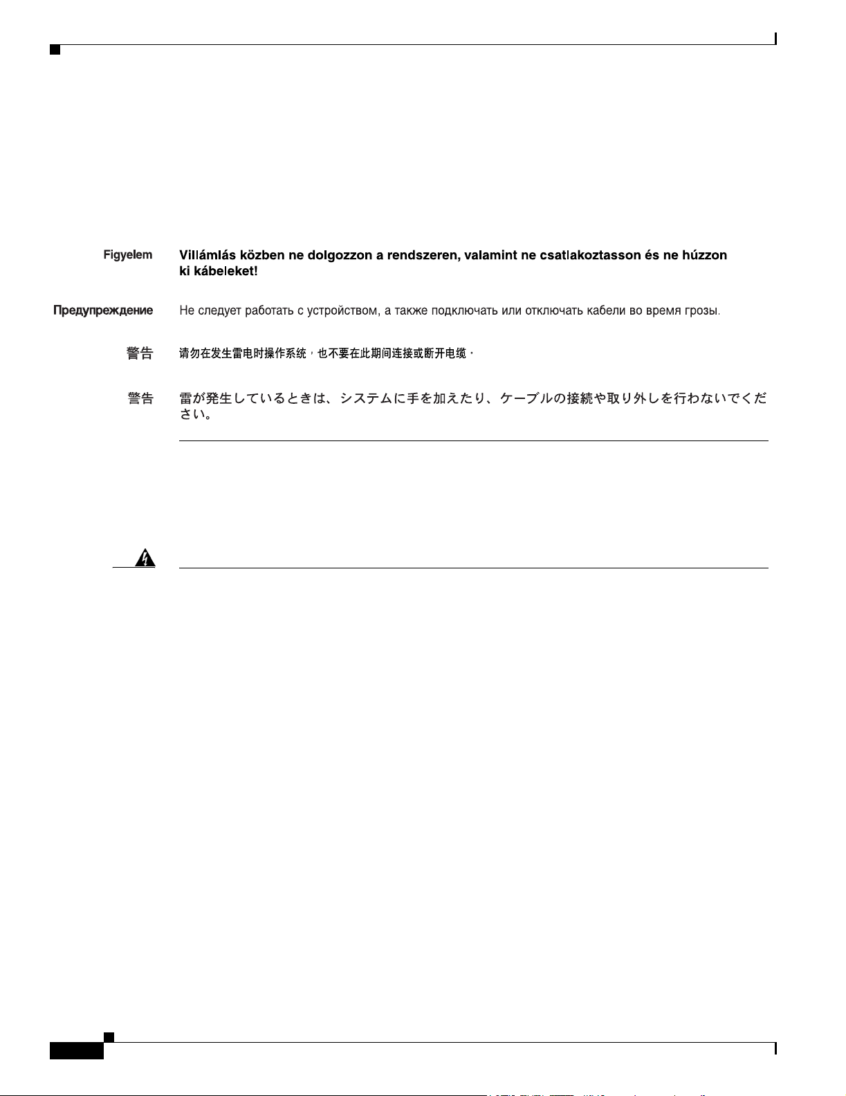
Statement 1005—Circuit Breaker
Appendix A Translated Safety Warnings
Aviso
¡Advertencia!
Varning!
Não trabalhe no sistema ou ligue e desligue cabos durante períodos de mau tempo (trovoada).
No operar el sistema ni conectar o desconectar cables durante el transcurso de descargas
eléctricas en la atmósfera.
Vid åska skall du aldrig utföra arbete på systemet eller ansluta eller koppla loss kablar.
Statement 1005—Circuit Breaker
Warning
Waarschuwing
Varoitus
Attention
Warnung
Avvertenza
Advarsel
This product relies on the building’s installation for short-circuit (overcurrent) protection. Ensure
that the protective device is rated not greater than: 15A
Statement 1005
Dit product is afhankelijk van de installatie van het gebouw voor beveiliging tegen kortsluiting
(overstroom). Controleer of de beschermingsinrichting niet meer dan: 15A .
Tämä tuote on riippuvainen rakennukseen asennetusta oikosulkusuojauksesta
ylivirtasuojauksesta). Varmista, että suojalaitteen mitoitus ei ole yli: 15A
Pour ce qui est de la protection contre les courts-circuits (surtension), ce produit dépend de
l'installation électrique du local. Vérifiez que le courant nominal du dispositif de protection n'est
pas supérieur à: 15A
Dieses Produkt ist darauf angewiesen, dass im Gebäude ein Kurzschluss- bzw. Überstromschutz
installiert ist. Stellen Sie sicher, dass der Nennwert der Schutzvorrichtung nicht mehr als: 15A .
Questo prodotto dipende dall'impianto dell'edificio per quanto riguarda la protezione contro
cortocircuiti (sovracorrente). Assicurarsi che il dispositivo di protezione non abbia un rating
superiore a: 15A
Dette produktet er avhengig av bygningens installasjoner av kortslutnings (overstrøm)-beskyttelse.
Påse at verneenheten ikke er merket høyere enn: 15A
A-6
Cisco Aironet 1300 Series Outdoor Access Point/Bridge Hardware Installation Guide
OL-5048-02
 Loading...